Embed Size (px)
Citation preview

RESEARCH PAPER
Continuum deformation and stability analysesof a steep hillside slope under rainfall infiltration
Ronaldo I. Borja • Joshua A. White
Received: 20 June 2009 / Accepted: 30 November 2009 / Published online: 8 January 2010
� Springer-Verlag 2010
Abstract Rainfall weakens an earth slope in a number of
ways. It increases the degree of saturation of the soil,
thereby breaking the bonds created by surface tension
between the soil particles. When the volume of infiltrating
water is large enough to mobilize fluid flow inside the soil
matrix, the fluid exerts a downhill frictional drag on the
slope, creating a destabilizing effect. When excess fluid can
no longer infiltrate the slope due to increased saturation in
the soil, it is discharged as a surface runoff and erodes the
slope. In this paper, we present a physics-based framework
for continuum modeling of a hydrologically driven slope
failure similar to what occurred in a steep experimental
catchment CB1 near Coos Bay, Oregon. We quantify the
rainfall-induced slope deformation and assess the failure
potential of the slope using finite element modeling that
couples solid deformation with fluid pressure in an unsat-
urated soil. Results of the studies suggest that for a steep
hillside slope underlain by a shallow bedrock similar to the
CB1 site, failure would occur by multiple slide blocks with
the failure surfaces emerging on the slope face. These
results suggest that an infinite slope mechanism would be
insufficient to represent the failure kinematics for a slope
similar to CB1.
Keywords Coupled formulation � Rainfall infiltration �Slope stability � Stabilized finite elements �Unsaturated soil
1 Introduction
Hydrologically driven slope instability threatens lives and
property worldwide. Examples of large-scale slope failure
all over the world are numerous. Landslides in the San
Francisco Bay Area during the January 1982 storm resulted
in 24 fatalities and millions of dollars in property damage
[18, 61]. In January 4, 1982, a 0.22-m storm superimposed
on approximately 0.6 m of pre-storm seasonal rainfall
triggered thousands of landslides in the central Coast
Ranges of California. In Mameyes, Puerto Rico, 1985,
rainfall intensity as high as 0.56 m within a 24-h period,
with rates as high as 70 mm/h, triggered debris flows and
resulted in 129 deaths [31]. In Rio Limon, Venezuela,
1987, rainfall as much as 0.174 m in less than 5 h triggered
numerous shallow landslides and debris flows resulting in
210 deaths [58]. In Antofagasta, Chile, 1991, rainfall rates
as great as 60 mm/h during a 3-h period triggered land-
slides that resulted in 101 deaths [66]. In Vargas, Vene-
zuela, 1999, a heavy rainfall exceeding 0.9 m over a 3-day
period, with daily values greater than the 1,000-year return
period [41], triggered thousands of landslides and resulted
in an estimated 30,000 deaths [65]. And in 2006, a heavy
rainfall in Guinsaugon, Philippines, triggered massive
landslides burying an elementary school that had 246
students and 7 teachers [37].
Despite decades of extensive slope-stability model
development, the fundamental controls connecting the
hydrologic and geotechnical processes triggering slope
failure are still not well quantified. This is evident from the
La Conchita landslide of January 11, 2005, in southern
California that occurred without warning. This lack of
understanding is a direct result of the simplified physics in
current models, with the omission of the effect of partial
saturation from slope-stability calculations. It is known that
R. I. Borja (&) � J. A. White
Department of Civil and Environmental Engineering,
Stanford University, Stanford, CA 94305, USA
e-mail: [email protected]
123
Acta Geotechnica (2010) 5:1–14
DOI 10.1007/s11440-009-0108-1

increasing the degree of saturation decreases the capillary
pressure, which in turn weakens the slope. Moreover, fluid
flow generates frictional drag on the soil matrix, thus
increasing the load that the soil is expected to carry.
Despite the expected significant impact, such interplay
between the increase in saturation accompanied by fluid
flow and increase in potential for slope failure is yet to be
fully quantified.
Rainfall-triggered slope instability has been the subject
of intense research for many years. Several studies are
available concerning field observations and laboratory
experiments (e.g., [47]). The modeling of the slope failure
process has been addressed in a variety of ways over the
years. The most common approach is to uncouple the fluid
flow and slope-stability problems, and instead treat them in
a sequential fashion. First, a representative pore-pressure
field is determined using either field-observations, analyt-
ical solutions, or numerical methods. The fixed pore-pres-
sure field is then used to determine slope stability either
analytically or numerically. Among these uncoupled
methods, the most common treatment of the slope-stability
sub-problem is through a limit equilibrium approach. For
example, see [29, 59] where infinite slope approximations
are used, and [17] where a simplified Janbu method of
slices is used. In [35, 49], a finite element solution for the
transient sub-surface seepage is combined with a method of
slices to determine a slope’s factor of safety. The key
advantage of these methods is their simplicity. Because the
solid and fluid sub-problems are uncoupled, sophisticated
methods and software that have been developed over the
years for the separate problems can be brought together.
These models also have relatively few parameters to cali-
brate, and solutions can be computed inexpensively. Fur-
thermore, it is easy to compute parameter sensitivities and
understand basic trends in the slope failure process. On the
downside, these models make many simplifying assump-
tions about the slope geometry, the coupled nature of the
failure process, the constitutive behavior of the soil, and the
in situ stress conditions.
In this paper, we develop and test a 3D physics-based
slope deformation model that couples solid deformation
with fluid flow in variably soils. We also assess the
potential of the coupled model to realistically quantify
stresses and deformation necessary to trigger slope failure.
We emphasize the continuum nature of the modeling
approach in that it does not quantify the factor of safety of
the slope per se, unlike methods based on limit equilibrium
concepts. Instead, our model predicts the spatial and tem-
poral variations of internal stresses, pore water pressure,
degree of saturation, and deformation within the slope, as
functions of the spatially and temporally varying rainfall
intensity. Thus, instead of having one scalar quantity called
factor of safety, we assess the failure potential of a given
slope based on the stresses and deformation arising from a
prescribed forcing function (i.e., rainfall intensity). Stabil-
ity criteria based on deformation bands are used in this
paper to assess the potential for slope failure.
To assess whether the proposed model can successfully
integrate important variables in a physics-based charac-
terization of the field conditions and still obtain a realistic
description of slope failure, we test the approach with
comprehensive and exhaustive data from the Coos Bay
experimental catchment (CB1) [21, 22]. The highly
instrumented site was originally chosen as a hillslope-scale
‘‘laboratory’’ for conducting sprinkling experiments aimed
at developing and testing hydrologic response models.
Experimental and field data generated from the site are
plentiful, albeit most of them pertain to hydrologic
response data [3, 43, 64]. However, the highly instru-
mented CB1 slope failed as a large debris flow in
November 1996, raising some interesting questions related
to the geotechnical aspects of the site. Given what we know
about the topography, hydrologic constraints, and the
geotechnical outcome at CB1, this case study seems ideal
to test the proposed continuum slope model. However, it
must be noted that despite much effort to constrain the site
with extensive field instrumentation and investigation,
much uncertainty remains particularly with respect to the
geotechnical and hydrologic boundary conditions appro-
priate for the site. Therefore, to underscore what we still do
not know about CB1, we emphasize that the analysis
reported in this paper pertains only to a slope similar to
CB1, and not to the slope at CB1 itself.
The slope at CB1 is steep, on the order of 43 degrees.
Any critical state soil mechanics model would predict an
initial stress condition within the slope that lies on the
‘‘dilatant side’’ of the critical state line because of the high
shear stress to effective-mean-normal stress ratio generated
by the steep slope condition [32, 44]. It would thus be
reasonable to characterize the constitutive response of the
soil skeleton with a Mohr–Coulomb plasticity or similar
models, since the compression cap is unlikely to be acti-
vated particularly when the effective-mean-normal stress
decreases further as a result of the loss of suction with
increased saturation. A simpler plasticity model such as the
Mohr–Coulomb model also requires fewer material
parameters than any of the more sophisticated constitutive
models available in the literature (see [76]). For the soil at
CB1, which is mostly colluvium, laboratory-determined
values of friction angle are available [53, 54]. Furthermore,
representative values of lateral root cohesion in clearcut
forests in the Oregon Coast Range have been estimated in
[55]. Finally, the thickness of the colluvium at CB1 is
known to be much smaller than the plan area of the
mobilized slide, thus making a continuum analysis
approach appropriate for this problem.
2 Acta Geotechnica (2010) 5:1–14
123

2 Continuum slope model
For a solid–water–air mixture the constitutive stress tensor
r0 (positive for tension) may be defined as
r0 ¼ rþ 1� K
Ks
� �p1; p ¼ wwpw þ ð1� wwÞpa; ð1Þ
where r is the total Cauchy stress tensor, ww is the degree
of saturation, K and Ks are the elastic bulk moduli for the
solid matrix and solid constituent, respectively, pw and pa
are the intrinsic pore water and pore air pressures,
respectively, and 1 is the Kronecker delta tensor. Borja [11,
15] demonstrated this expression for the constitutive stress
tensor to be energy-conjugate to the solid rate of defor-
mation. Under special cases, r0 reduces to Bishop’s stress
when K/Ks = 0 (incompressible solid grains) and ww = v;
to the Skempton [60] and Nur-Byerlee [45] stress when
ww = 1; and to the Terzaghi [62] stress when K/Ks = 0
and ww = 1. The Bishop parameter v can be determined
experimentally [6, 40], and the substitution of degree of
saturation ww in lieu of this parameter is a simplified
approximation derived from the volume averaging over a
so-called representative elementary volume, REV. For
purposes of constitutive modeling of the soil layer, we will
use the Bishop stress (K/Ks = 0), with v = ww.
Ignoring inertia forces and setting pa equal to the
atmospheric pressure (i.e., zero) for near-surface condition,
balance of linear momentum in the sub-surface is given by
the equation
r � rþ qg ¼ 0; q ¼ /sqs þ /wqw; ð2Þ
where /s and /w are the solid and water volume fractions
in the REV, respectively; qs and qw are the intrinsic solid
and water mass densities (i.e., mass of constituent a per
unit volume of constituent a), respectively; q is the total
mass density of the mixture (ignoring the mass of air
phase); and g is the gravity acceleration vector. Assuming
that water is incompressible, balance of water mass in the
sub-surface takes the form [10, 11]
d/w
dtþ /wr � vþr � qw ¼ �hb � he; ð3Þ
where v is the velocity of the solid matrix, qw ¼ /wðvw � vÞis the relative discharge velocity, hb is the specified rate
source/sink, he is the rate of water exchange with the surface
continuum, and d(�)/dt denotes a material time derivative
following the solid motion. The relative discharge velocity is
given by the constitutive equation
qw ¼ krwK � r pw
qwgþ z
� �; ð4Þ
where K is the hydraulic conductivity of the porous med-
ium at complete saturation, krw is the relative permeability
that varies with degree of saturation ww, g is the gravity
acceleration constant, and z is the vertical coordinate.
The two independent variables of the formulation are the
solid velocity v and pore water pressure pw satisfying the
two balance laws (2) and (3), along with the appropriate
boundary and initial conditions. The solution is fully cou-
pled in the sense that the independent variables are deter-
mined simultaneously. However, the governing equations
must be closed by introducing a pair of constitutive laws
determined from continuum principles of thermodynamics
[10, 11, 15, 26, 27, 30, 34, 39, 46]: (a) a constitutive law
relating the Cauchy effective stress rate tensor _r0 with the
strain rate tensor rsv for the solid matrix; and (b) a con-
stitutive law relating the suction stress s = pa - pw with
degree of saturation ww. The second constitutive law is
determined from the imbibition portion of the soil-water
retention curve for a given soil [7, 67].
Continuum principles of thermodynamics suggest an
elasto-plastic constitutive framework for the soil skeleton
given by a yield function of the form [10, 11, 15, 26, 27]
Fðr0; s; pcÞ ¼ 0; ð5Þ
where pc is a stress-like plastic internal variable that
determines the size of the compression cap. The suction
stress has a positive value for negative pore water pressure
(e.g., above the water table) and approaches zero as the soil
approaches perfect saturation. However, as noted earlier,
the compression cap is not likely to be activated for steep
hillside slope conditions, and thus, this explicit dependence
of the yield surface on the suction stress may be ignored
when using the Mohr–Coulomb or similar yield criteria.
We emphasize, however, that the yield function still
depends on the suction stress through the Cauchy effective
stress tensor r0:Mixed finite element (FE) equations may be readily
developed from the variational forms of (2) and (3). The
independent variables in the present case are the nodal
solid displacement vector d and nodal pore water pressure
vector p. The coupled FE equations take the form
FINTðdÞ þ Gp ¼ FEXT; ð6Þ
GT _d þM _pþ Up ¼ GEXT; ð7Þ
where FINTðdÞ is the internal nodal force vector arising
from the effective stress r0, G and GT are the discrete
gradient and discrete divergence operators, respectively,
which depend on p through the degree of saturation Sr in
the unsaturated regime, M is a coupling matrix that van-
ishes at full saturation, U is an effective conductivity
matrix that also depends on the degree of saturation, and
FEXT and GEXT are prescribed vectors of momentum and
fluid supplies. Note that the degree of coupling implied by
the earlier equations is more intricate than in the fully
Acta Geotechnica (2010) 5:1–14 3
123
saturated case because of the presence of ww in many
terms.
The coupled formulation presented earlier requires
mixed finite elements with nodal pressure and displace-
ment degrees of freedom. Low-order mixed finite elements,
with equal order interpolation for displacement and pres-
sure, would be ideal particularly in 3D when the number of
equations can increase dramatically. Unfortunately, low-
order mixed finite elements create a numerical difficulty in
that in the limit of full saturation and either low perme-
ability or fast loading rates, the pore fluid can impose near
or exact incompressibility on the deformation of the solid
matrix and create spurious pore-pressure oscillation. To
address this difficulty, we use a stabilization scheme pro-
posed by White and Borja [73] based on the concept of
polynomial pressure projections (PPP), which was origi-
nally proposed in [8, 9, 20] to stabilize the Stokes problem.
The primary motivation for using stabilization is compu-
tational efficiency: with this technique, it would now be
possible to use low-order finite elements, such as those
shown in Fig. 1, without the undesirable pore-pressure
oscillation that otherwise afflicts the solution without
stabilization.
3 Hydrologic and geotechnical conditions at CB1
The CB1 experimental catchment [3, 43, 64], clearcut in
1987, is located along Mettman Ridge approximately
15 km north of Coos Bay in the Oregon Coast Range
(Fig. 2). CB1 is a 51-m long (860 m2) unchanneled valley,
with a north-facing aspect, that has an average slope of 43�(see Fig. 3). Three sprinkling experiments were conducted
at CB1: experiment #1 conducted in May 1990 at 1.5 mm/
h for 6 days; experiment #2 conducted in May 1990 at 3.0
mm/h for 4 days; and experiment #3 conducted in May
1992 at 1.7 mm/h for 7 days. The instrumentation at CB1
used to characterize the spatial and temporal variability in
near-surface hydrologic response for the three experiments
included an exhaustive grid of rain gauges, piezometers,
tensiometers, TDR wave guide pairs (for estimating soil-
water content), lysimeters, meteorological sensors (on a
tower), atmometers, and weirs. Continuous measurements
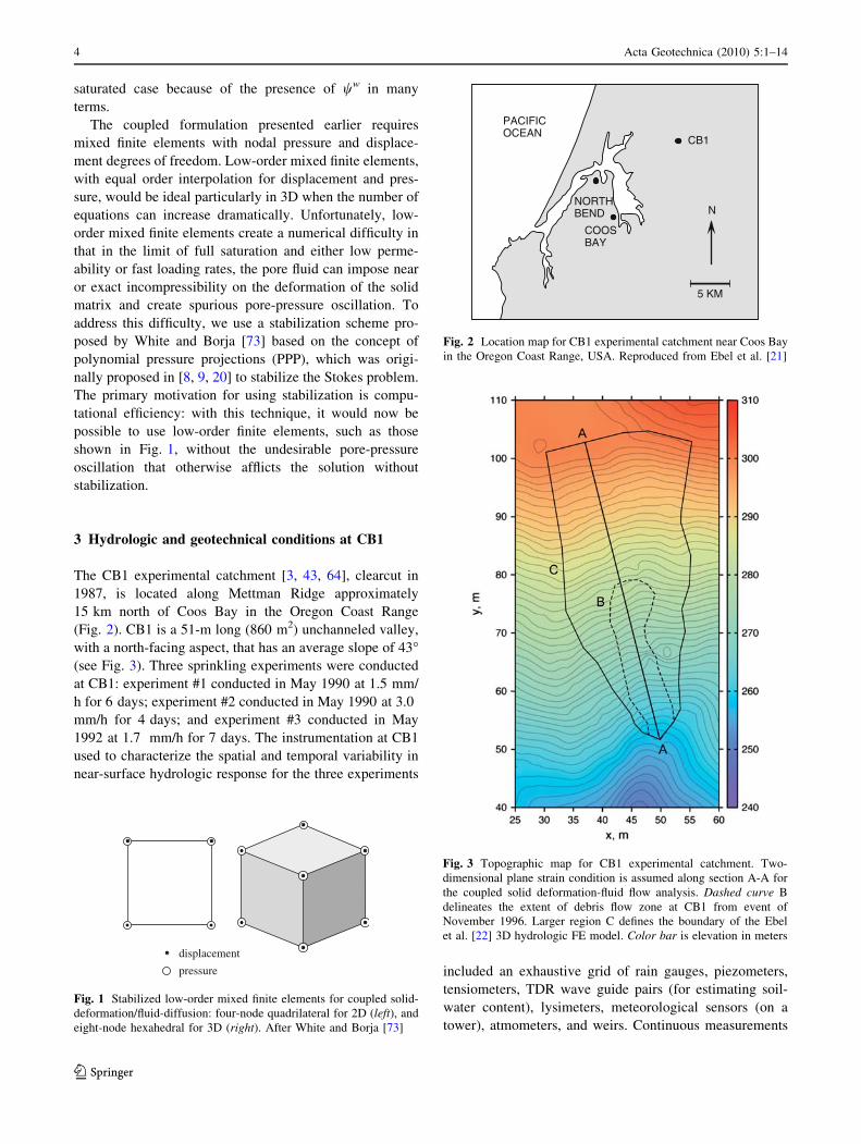
displacement
pressure
Fig. 1 Stabilized low-order mixed finite elements for coupled solid-
deformation/fluid-diffusion: four-node quadrilateral for 2D (left), and
eight-node hexahedral for 3D (right). After White and Borja [73]
PACIFICOCEAN
NORTHBEND
COOSBAY
CB1
N
5 KM
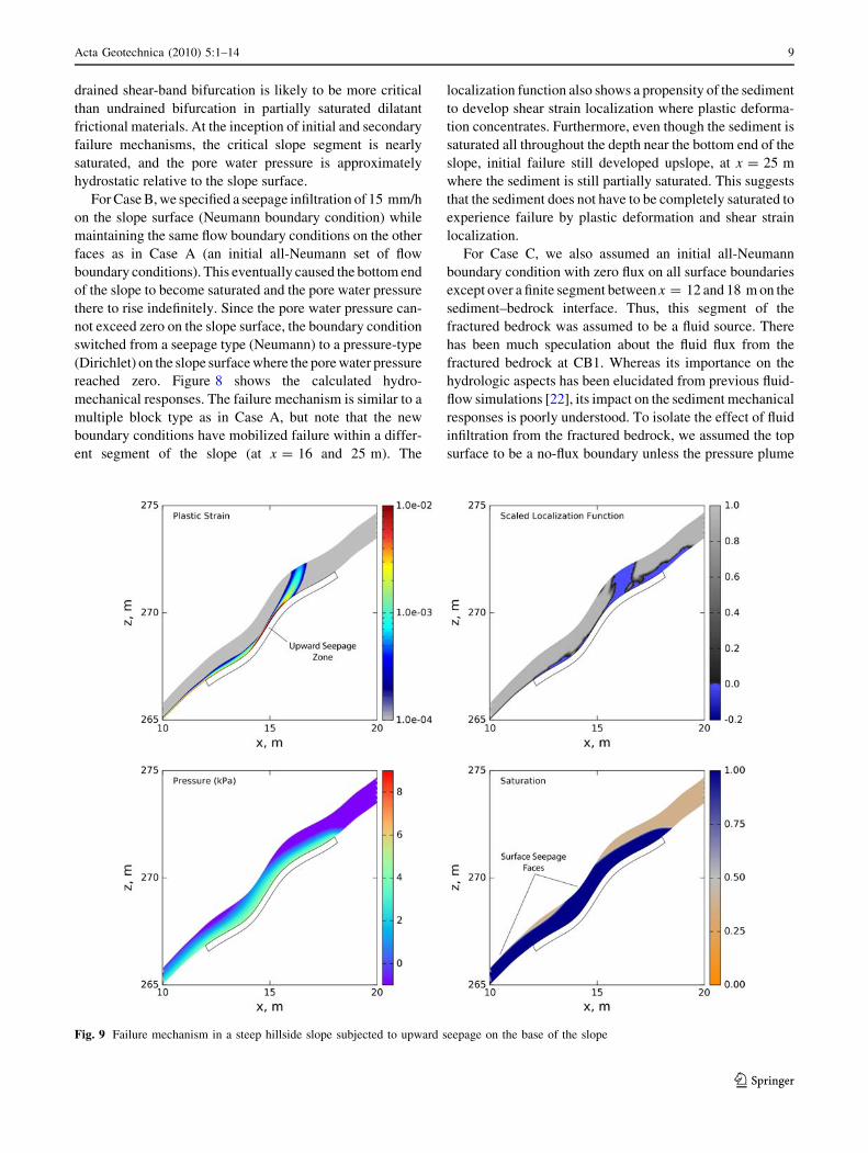
Fig. 2 Location map for CB1 experimental catchment near Coos Bay
in the Oregon Coast Range, USA. Reproduced from Ebel et al. [21]
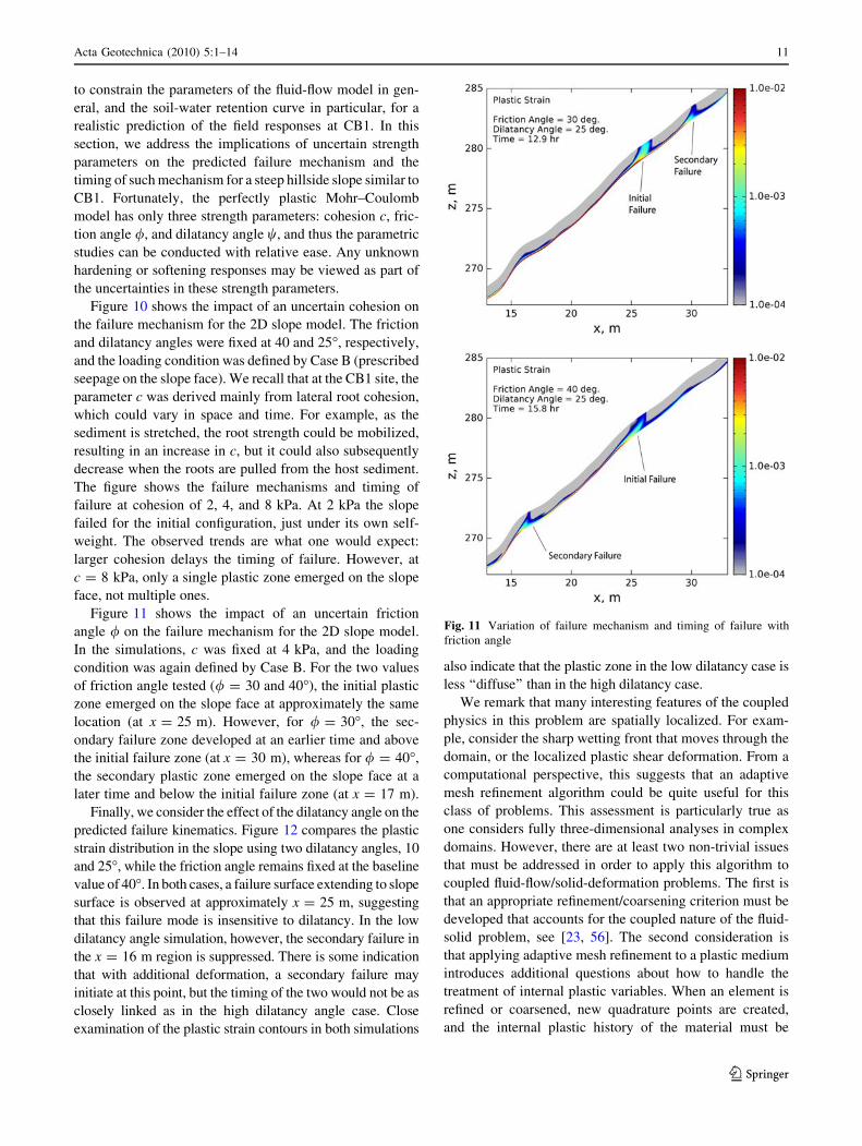
Fig. 3 Topographic map for CB1 experimental catchment. Two-
dimensional plane strain condition is assumed along section A-A for
the coupled solid deformation-fluid flow analysis. Dashed curve B
delineates the extent of debris flow zone at CB1 from event of
November 1996. Larger region C defines the boundary of the Ebel
et al. [22] 3D hydrologic FE model. Color bar is elevation in meters
4 Acta Geotechnica (2010) 5:1–14
123

from rainfall, discharge, and total head (from selected
piezometers) are available from 1990 through 1996. In
November 1996, the CB1 slope failed as a large debris
flow. The instrumentation at CB1 provides one of the most
comprehensive hydrologic response data sets in existence
for a steep, deforested catchment that has experienced
slope failure.
The sediment at CB1 is colluvium, a surficial sedi-
ment derived from weathered or fresh bedrock, and the
soil has no input from aeolian transport. The parent rock
for the colluvium is an Eocene turbidite sandstone from
the Tyee and Flournoy formations [55]. The soils are
well mixed, non-plastic (plasticity index of 0), and
gravelly sands [54]. The geometry and thickness of the
colluvium are well defined from soil borings. Saturated
hydraulic conductivity were determined from slug tests,
soil-water content, and porosity from TDR measure-
ments, and hysteretic capillary pressure relationships
were established from experiments. Discharge chemistry
data suggest that runoff generation occurs primarily from
water stored in small, poorly connected pores, and
fractures in the bedrock, and saprolite connecting with
larger macropores during storms [42]. Tracer data (bro-
mide and isotopically tagged water) suggest that the two
most important flow paths at CB1 are rapid saturated
flow through the shallow, fractured bedrock, and vertical
percolation in the vadose zone [2]. Piezometer records
show that sub-surface storm flow in the shallow, frac-
tured-rock zone exerts the most significant control on
pore-pressure development in the CB1 colluvium [42].
Tensiometer data indicate that the flux of water through
the unsaturated zone provides an additional control on
pore-pressure development and cannot be ignored in
slope-stability assessment models [63].
Low confining stress triaxial shear tests demonstrate
that the colluvium at CB1 is cohesionless (consisting of
a sandy matrix with a friction angle of 33�) [53, 54].
Lateral root cohesion in clearcut forests in the Oregon
Coast Range was estimated to be uniformly less than
10 kPa [55] and may have explained how such a steep
slope at CB1 could be sustained by the sediment (apart
from the capillary tension that develops in the vadose
zone). Low confining stress triaxial tests gave an internal
friction angle of 40� and zero cohesion [55]. This is in
agreement with other measurements near the site that
gave internal friction angles ranging from 35–44� [19,
57, 74, 75] and zero cohesion [75]. The stress-strain
behavior, observed in low confining stress triaxial
strength testing, was approximately linear for low
applied stresses with a distinct transition to a non-linear
material behavior at axial strains greater than 1–2% [54].
The saturated density of the soil is about 1,600 kg/cu.m.
[55], and the bulk density at soil water contents of
20–30% is around 1,200 kg/cu.m. [54]. The Van Ge-
nuchten [28, 67] parameters for the CB1 soil are dis-
cussed in the next section.
4 Hydro-mechanical model
A challenging aspect of the numerical simulation of a
hillslope-scale problem is determining the extent of the
spatial and temporal discretizations, and what initial and
boundary conditions to impose on the problem. Ebel et al.
[22] conducted full 3D fluid flow simulations based on
Richards equation of variably saturated flow in the sub-
surface [50] using a comprehensive FE code InHM (Inte-
grated Hydrology Model) [68]. They simulated flow over a
portion of the sediment and fractured bedrock delineated
by vertical boundaries on which they believed they could
reasonably impose a no-flow boundary condition. The
spatial extent of their domain description is shown in
Fig. 3.
For our purposes, the deformation in the bedrock
would be too small to be of concern in the coupled solid
deformation/fluid-flow analysis, and thus we only repre-
sent the sediment domain in our simulations. However,
there are two important factors that make the present
simulations significantly more demanding than the fluid-
flow simulations conducted by Ebel et al. [22]: (a) each
node in the FE mesh is now composed of 3 degrees of
freedom (DOFs) in 2D (two displacement and one
pressure), and 4 DOFs in 3D (three displacement and
one pressure); thus, the number of equations increases
very fast; and (b) the water retention curve typically
exhibits a steep slope near the wetting front, necessitat-
ing a high-resolution mesh everywhere in the unsaturated
zone (since the wetting front propagates through the
unsaturated zone).
Considering the difficulty with modeling the exact
CB1 conditions due to the uncertainties in defining what
constitutes a ‘sufficient’ 3D representation of CB1 and
what boundary conditions to impose on this model, we
believe that it would be more enlightening to consider a
much simpler 2D plane strain representation for now,
where the boundary conditions can be constrained more
easily. To this end, we selected a cross-section passing
through the steepest portion of the CB1 catchment,
shown as section A-A in Fig. 3, and constructed the FE
mesh shown in Fig. 4. This 2D representation of the
slope at CB1 is conservative in the sense that out-of-
plane strengths from 3D effect emanating from lateral
root cohesion, friction, etc. has been ignored. The mesh
shown in Fig. 4 has 20,000 nodes and 18,981 (stabilized)
quadrilateral mixed finite elements, resulting in a total of
60,000 DOFs.
Acta Geotechnica (2010) 5:1–14 5
123

Figures 5 and 6 show the suction/saturation and satu-
ration/relative permeability relationships used in the sim-
ulations. The degree of saturation Sr is determined from the
Van Genuchten [67] model as
wwðsÞ ¼ w1 þ ðw2 � w1Þ 1þ s
sa
� �n� ��m
: ð8Þ
The model contains four parameters: w1 is the residual
water saturation, w2 is the maximum water saturation, sa is
a scaling pressure, and n and m are empirical constants
defining the shape of the saturation curve. The constants n
and m are not independent but are rather related to one
another as
m ¼ n� 1
n: ð9Þ
The water phase relative permeability is similarly defined
as
krwðhÞ ¼ h1=2 1� 1� h1=m� �mh i2
; h ¼ ww � w1
w2 � w1
ð10Þ
The parameter values used in this work are given in
Table 1. In order to calibrate the model, we have used the in
situ retention curves as measured by Torres et al. [64] for the
CB1 site. We ignored hysteretic effects and have only used
the wetting measurements for calibration. The chosen values
0.5 m
MESH DETAIL
300
0 26.3 52.6
METERS
290
280
270
260ELE
VA
TIO
N, M
ET
ER
S
Fig. 4 Finite element mesh for CB1-like problem simulations (cf.
section A-A in Fig. 3)
60
50
40
30
20
10
0
WA
TE
R C
ON
TE
NT
, %
DE
GR
EE
OF
SA
TU
RA
TIO
N, %
100
80
60
40
20
0
SUCTION, KPA
0 5 10 15 20
WETTINGDRYING
WETTINGDRYING
MEASURED:EBEL ET AL (2007):
Fig. 5 Soil-water retention curve data [64] and van Genuchten
curves used by Ebel et al. [22] for hydrologic simulations. We use
(approximately) the Ebel et al. [22] wetting curve for the saturation-
suction relation to capture the mechanical response during the wetting
phase of the numerical simulations
DEGREE OF SATURATION, %0 20 40 60 80 100
0
2
4
6
8LOG
RE
LAT
IVE
PE
RM
EA
BIL
ITY
Fig. 6 Variation of relative permeability with degree of saturation
based on the wetting curve
Table 1 Material parameters
Intrinsic permeability k 3.4 9 10-11 m2
Fluid viscosity l 1.0 9 10-6 kPa s
Residual saturation w1 0.32
Maximum saturation w2 1.00
Shape constant n 3.00
Scaling pressure sa 0.40 kPa
Bulk modulus K 50 MPa
Poisson ratio m 0.25
Cohesion c 0–10 kPa
Friction angle / 33–40�Dilatancy angle w & 25�Porosity /s 0.50
Fluid density qw 1.0 Mg/m3
Solid density qs 2.2 Mg/m3
6 Acta Geotechnica (2010) 5:1–14
123

are nearly the same as those used by Ebel et al. [22] in their
hydrologic model except for a slight adjustment in the
scaling pressure. The steep geometry of the saturation and
relative permeability relationships proved to be numerically
challenging on the relatively coarse mesh, and a slight flat-
tening of the curve improved the robustness of the model.
The elastic parameters K and m are typical for sand/
gravel mixture subjected to a confining pressure compa-
rable to those prevailing in the CB1 sediment [36]. The
elastic parameters influence the displacements of the sed-
iment but have little effect on the mechanism of failure,
which is determined largely by the plasticity model. The
parameters of the Mohr–Coulomb plasticity model are the
cohesion c, friction angle /, and dilatancy angle w, and
their range of values is also summarized in Table 1.
5 Results
In general, failure mechanisms generated by the 2D slope
model are complex and very much dependent on the
imposed flow boundary conditions. Furthermore, the tim-
ing and location of initial failure are dependent on the
intensity of rainfall and local flow conditions, such as the
presence of a source or sink. In this section, we summarize
the results of numerical simulations on the 2D slope model.
The section is divided into two parts. In the first part, we
show the impact of flow boundary conditions on the
resulting deformation and failure patterns. In the second
part, we conduct parametric studies to investigate the
sensitivity of the calculated deformation and failure pat-
terns to variation in material parameters.
5.1 Impact of flow boundary conditions
We consider three fluid-flow boundary conditions—Case A:
a zero fluid pressure is prescribed on the slope surface; Case
B: rainfall infiltration is prescribed on the slope surface in the
form of fluid flux; and Case C: fluid infiltration into the
sediment is prescribed on the interface between the sediment
and fractured bedrock. The materials parameters are sum-
marized in Table 1. For the present simulations, baseline
Fig. 7 Multiple slide block mechanism in a steep hillside slope subjected to rising pore water pressure boundary condition from -1.5 kPa up to
0 kPa in 3 h on slope surface
Acta Geotechnica (2010) 5:1–14 7
123

values of c = 4 kPa for cohesion, / = 40� for friction angle,
and w = 25� for dilatancy angle were used.
In all the simulations, the sediment was assumed fixed to
the bedrock, and any relative sliding between the sediment
and bedrock may only take place in the form of plastic
deformation on the sediment. The slope is very thin com-
pared to its length, so the displacement boundary conditions
on the top and bottom ends of the slope are expected to play a
very minor role on the calculated mechanical responses.
Thus, in the present simulations, we simply assumed the top
and bottom ends of the slope to be fixed to the support.
However, initial conditions do play a significant role on the
hydro-mechanical responses, particularly the initial value of
negative pore water pressure within the sediment. Based on
the hydrologic simulations of Ebel et al. [22], we assumed an
initial pore water pressure of -1.5 kPa throughout the sed-
iment. Gravity load was turned on along with this initial pore
water pressure to obtain the initial effective stresses, after
which the nodal displacements were reset to zero. A standard
2 9 2 Gauss integration rule was used for the stabilized
quadrilateral mixed elements, and a backward implicit
scheme was used for time integration.
For Case A, we assumed the pore water pressure on the
slope surface to ramp up linearly from -1.5 kPa at t = 0, to
0 kPa at t = 3 h (Dirichlet boundary condition), with all
other fluid-flow boundaries assumed to be impermeable
(Neumann boundary condition). This represents a heavy
rainfall, enough to saturate the slope surface within a period
of 3 h and keep it saturated thereafter. Figure 7 summarizes
the calculated hydro-mechanical responses at the inception
of primary and secondary failure mechanisms within the
slope. The general mechanism is as follows. As the sediment
becomes saturated, local plastic zones develop on the base
and stretch the slope segments unevenly. Eventually, plastic
zones curve upwards due to local stretching of the slope
segments and emerge on the ground surface approximately at
coordinates x = 43 and 50 m. The resulting slope failure
mechanism is similar to multiple slide block described by
Varnes [69]. Drained bifurcation analyses based on the
Rudnicki and Rice [51] procedure allowed the calculation of
localization function [4, 5, 11, 12, 13, 14, 52], showing
negative values. This suggests that a shear band-type bifur-
cation is likely to occur where the plastic deformation con-
centrates. On a related note, Borja [10] demonstrated that
Fig. 8 Multiple slide block mechanism in a steep hillside slope subjected to rainfall infiltration of 15 mm/h on slope surface
8 Acta Geotechnica (2010) 5:1–14
123
drained shear-band bifurcation is likely to be more critical
than undrained bifurcation in partially saturated dilatant
frictional materials. At the inception of initial and secondary
failure mechanisms, the critical slope segment is nearly
saturated, and the pore water pressure is approximately
hydrostatic relative to the slope surface.
For Case B, we specified a seepage infiltration of 15 mm/h
on the slope surface (Neumann boundary condition) while
maintaining the same flow boundary conditions on the other
faces as in Case A (an initial all-Neumann set of flow
boundary conditions). This eventually caused the bottom end
of the slope to become saturated and the pore water pressure
there to rise indefinitely. Since the pore water pressure can-
not exceed zero on the slope surface, the boundary condition
switched from a seepage type (Neumann) to a pressure-type
(Dirichlet) on the slope surface where the pore water pressure
reached zero. Figure 8 shows the calculated hydro-
mechanical responses. The failure mechanism is similar to a
multiple block type as in Case A, but note that the new
boundary conditions have mobilized failure within a differ-
ent segment of the slope (at x = 16 and 25 m). The
localization function also shows a propensity of the sediment
to develop shear strain localization where plastic deforma-
tion concentrates. Furthermore, even though the sediment is
saturated all throughout the depth near the bottom end of the
slope, initial failure still developed upslope, at x = 25 m
where the sediment is still partially saturated. This suggests
that the sediment does not have to be completely saturated to
experience failure by plastic deformation and shear strain
localization.
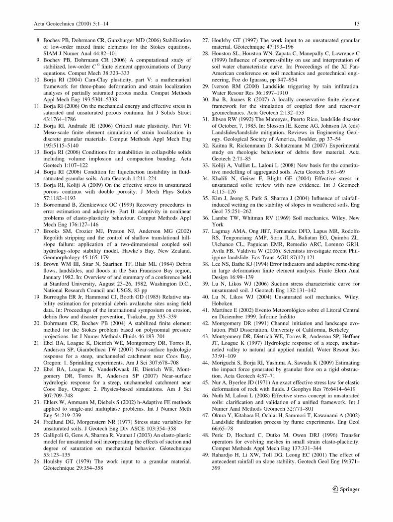
For Case C, we also assumed an initial all-Neumann
boundary condition with zero flux on all surface boundaries
except over a finite segment between x = 12 and 18 m on the
sediment–bedrock interface. Thus, this segment of the
fractured bedrock was assumed to be a fluid source. There
has been much speculation about the fluid flux from the
fractured bedrock at CB1. Whereas its importance on the
hydrologic aspects has been elucidated from previous fluid-
flow simulations [22], its impact on the sediment mechanical
responses is poorly understood. To isolate the effect of fluid
infiltration from the fractured bedrock, we assumed the top
surface to be a no-flux boundary unless the pressure plume
Fig. 9 Failure mechanism in a steep hillside slope subjected to upward seepage on the base of the slope
Acta Geotechnica (2010) 5:1–14 9
123

reaches it, at which point it switches to a p = 0 face. Figure 9
suggests that with only fluid influx from the fractured bed-
rock, it takes a large amount of seepage to build up enough
pressure to fail the slope. Note that the pressure plume
extends all the way to the surface, implying that upward
seepage would be observed at the surface. It thus appears that
upward seepage is unlikely to be the primary failure mech-
anism for a slope similar to CB1. However, upward seepage
could certainly aggravate a slope that has already been
weakened by other infiltration.
5.2 Impact of strength parameters variation on failure
mechanism
The comprehensive hydrologic FE simulations conducted
by Ebel et al. [22] highlighted the importance of being able
Fig. 10 Variation of failure mechanism and timing of failure with cohesion
10 Acta Geotechnica (2010) 5:1–14
123
to constrain the parameters of the fluid-flow model in gen-
eral, and the soil-water retention curve in particular, for a
realistic prediction of the field responses at CB1. In this
section, we address the implications of uncertain strength
parameters on the predicted failure mechanism and the
timing of such mechanism for a steep hillside slope similar to
CB1. Fortunately, the perfectly plastic Mohr–Coulomb
model has only three strength parameters: cohesion c, fric-
tion angle /, and dilatancy angle w, and thus the parametric
studies can be conducted with relative ease. Any unknown
hardening or softening responses may be viewed as part of
the uncertainties in these strength parameters.
Figure 10 shows the impact of an uncertain cohesion on
the failure mechanism for the 2D slope model. The friction
and dilatancy angles were fixed at 40 and 25�, respectively,
and the loading condition was defined by Case B (prescribed
seepage on the slope face). We recall that at the CB1 site, the
parameter c was derived mainly from lateral root cohesion,
which could vary in space and time. For example, as the
sediment is stretched, the root strength could be mobilized,
resulting in an increase in c, but it could also subsequently
decrease when the roots are pulled from the host sediment.
The figure shows the failure mechanisms and timing of
failure at cohesion of 2, 4, and 8 kPa. At 2 kPa the slope
failed for the initial configuration, just under its own self-
weight. The observed trends are what one would expect:
larger cohesion delays the timing of failure. However, at
c = 8 kPa, only a single plastic zone emerged on the slope
face, not multiple ones.
Figure 11 shows the impact of an uncertain friction
angle / on the failure mechanism for the 2D slope model.
In the simulations, c was fixed at 4 kPa, and the loading
condition was again defined by Case B. For the two values
of friction angle tested (/ = 30 and 40�), the initial plastic
zone emerged on the slope face at approximately the same
location (at x = 25 m). However, for / = 30�, the sec-
ondary failure zone developed at an earlier time and above
the initial failure zone (at x = 30 m), whereas for / = 40�,
the secondary plastic zone emerged on the slope face at a
later time and below the initial failure zone (at x = 17 m).
Finally, we consider the effect of the dilatancy angle on the
predicted failure kinematics. Figure 12 compares the plastic
strain distribution in the slope using two dilatancy angles, 10
and 25�, while the friction angle remains fixed at the baseline
value of 40�. In both cases, a failure surface extending to slope
surface is observed at approximately x = 25 m, suggesting
that this failure mode is insensitive to dilatancy. In the low
dilatancy angle simulation, however, the secondary failure in
the x = 16 m region is suppressed. There is some indication
that with additional deformation, a secondary failure may
initiate at this point, but the timing of the two would not be as
closely linked as in the high dilatancy angle case. Close
examination of the plastic strain contours in both simulations
also indicate that the plastic zone in the low dilatancy case is
less ‘‘diffuse’’ than in the high dilatancy case.
We remark that many interesting features of the coupled
physics in this problem are spatially localized. For exam-
ple, consider the sharp wetting front that moves through the
domain, or the localized plastic shear deformation. From a
computational perspective, this suggests that an adaptive
mesh refinement algorithm could be quite useful for this
class of problems. This assessment is particularly true as
one considers fully three-dimensional analyses in complex
domains. However, there are at least two non-trivial issues
that must be addressed in order to apply this algorithm to
coupled fluid-flow/solid-deformation problems. The first is
that an appropriate refinement/coarsening criterion must be
developed that accounts for the coupled nature of the fluid-
solid problem, see [23, 56]. The second consideration is
that applying adaptive mesh refinement to a plastic medium
introduces additional questions about how to handle the
treatment of internal plastic variables. When an element is
refined or coarsened, new quadrature points are created,
and the internal plastic history of the material must be
Fig. 11 Variation of failure mechanism and timing of failure with
friction angle
Acta Geotechnica (2010) 5:1–14 11
123

transferred to these new points. For a simple plasticity
model (such as MC), a straightforward projection/interpo-
lation method may be sufficient, but for more complex
models (say, a critical state soil model) with several
internal parameters, we must develop a refinement strategy
that ensures that the plastic variables remain self-consistent
with one another as projection or interpolation operations
proceed, see [16, 38, 48].
6 Summary and conclusions
We have presented a continuum physics-based framework
for analysis of coupled solid deformation-fluid-flow pro-
cesses in partially saturated earthen slopes. The formula-
tion for constitutive modeling of the unsaturated sediment
is based on the use of an effective stress measure that
represents the sole stress state variable responsible for
deforming the solid skeleton, and on direct use of suction
in the constitutive relations [10, 11, 15, 33]. Other
alternative approaches exist, in which different pairs of
stress state variables are chosen instead of a single effective
stress, such as the net stress and matric suction [1, 24,25,
70–72]. However, the effective stress used in this work
appears to have an advantage in terms of FE implementa-
tion, since the coupled formulation follows exactly the
same lines as those developed for the fully saturated case.
This implies that stabilized low-order mixed FE elements
can be used just as well for the unsaturated case.
We have used the coupled continuum FE model to
analyze the deformation and stability of a steep hillside
slope similar to the CB1 site. Despite the simplified 2D
plane strain representation adopted by the model, the pre-
dicted failure mechanisms are complex and nowhere near
what one would normally obtain from an infinite slope
assumption. For a steep hillside slope similar to CB1, it
appears that failure mechanism would likely initiate in the
form of multiple failure blocks, which could transform into
a debris flow similar to what was observed at the CB1 site
during the November 1996 event. An obvious advantage of
the proposed continuum modeling approach lies in its
ability to integrate important hydro-mechanical processes
responsible for triggering rainfall-induced movement of
earthen slopes, including increased saturation, fluid flow,
and inelastic solid deformation. Work is currently under-
way to incorporate 3D effects into the numerical model.
Acknowledgments This work is supported by the US National
Science Foundation under Contract Numbers CMMI-0824440 and
CMMI-0936421 to Stanford University. The second author
acknowledges support from the US National Science Foundation
Graduate Research Fellowship and the Stanford Graduate Fellowship
Programs. We wish to thank Drs. Keith Loague and Brian Ebel for
numerous discussions pertaining to the CB1 problem. We are also
grateful to two anonymous reviewers for their constructive reviews.
References
1. Alonso EE, Gens A, Josa A (1990) A constitutive model for
partially saturated soils. Geotechnique 40:405–430
2. Anderson SP (1995) Flow paths, solute sources, weathering, and
denudation rates: the chemical geomorphology of a small
catchment. PhD Dissertation, University of California, Berkeley
3. Anderson SP, Dietrich WE, Montgomery DR, Torres R, Conrad
ME, Loague K (1997) Subsurface flowpaths in a steep, unchan-
neled catchment. Water Resour Res 33:2637–2653
4. Andrade JE, Borja RI (2006) Capturing strain localization in
dense sands with random density. Int J Numer Methods Eng
67:1531–1564
5. Andrade JE, Borja RI (2007) Modeling deformation banding in
dense and loose fluid-saturated sands. Finite Elem Anal Design
43:361–383
6. Arifin YF, Schanz T (2009) Osmotic suction of highly plastic
clays. Acta Geotech 4:177–191
7. Birle E, Heyer D, Vogt N (2008) Influence of the initial water
content and dry density on the soil-water retention curve and the
shrinkage behavior of a compacted clay. Acta Geotech 3:191–200
Fig. 12 Variation of failure mechanism and timing of failure with
dilatancy angle
12 Acta Geotechnica (2010) 5:1–14
123
8. Bochev PB, Dohrmann CR, Gunzburger MD (2006) Stabilization
of low-order mixed finite elements for the Stokes equations.
SIAM J Numer Anal 44:82–101
9. Bochev PB, Dohrmann CR (2006) A computational study of
stabilized, low-order C 0 finite element approximations of Darcy
equations. Comput Mech 38:323–333
10. Borja RI (2004) Cam-Clay plasticity, part V: a mathematical
framework for three-phase deformation and strain localization
analyses of partially saturated porous media. Comput Methods
Appl Mech Eng 193:5301–5338
11. Borja RI (2006) On the mechanical energy and effective stress in
saturated and unsaturated porous continua. Int J Solids Struct
43:1764–1786
12. Borja RI, Andrade JE (2006) Critical state plasticity. Part VI:
Meso-scale finite element simulation of strain localization in
discrete granular materials. Comput Methods Appl Mech Eng
195:5115–5140
13. Borja RI (2006) Conditions for instabilities in collapsible solids
including volume implosion and compaction banding. Acta
Geotech 1:107–122
14. Borja RI (2006) Condition for liquefaction instability in fluid-
saturated granular soils. Acta Geotech 1:211–224
15. Borja RI, Koliji A (2009) On the effective stress in unsaturated
porous continua with double porosity. J Mech Phys Solids
57:1182–1193
16. Boroomand B, Zienkiewicz OC (1999) Recovery procedures in
error estimation and adaptivity. Part II: adaptivity in nonlinear
problems of elasto-plasticity behaviour. Comput Methods Appl
Mech Eng 176:127–146
17. Brooks SM, Crozier MJ, Preston NJ, Anderson MG (2002)
Regolith stripping and the control of shallow translational hill-
slope failure: application of a two-dimensional coupled soil
hydrology-slope stability model, Hawke’s Bay, New Zealand.
Geomorphology 45:165–179
18. Brown WM III, Sitar N, Saarinen TF, Blair ML (1984) Debris
flows, landslides, and floods in the San Francisco Bay region,
January 1982. In: Overview of and summary of a conference held
at Stanford University, August 23–26, 1982, Washington D.C.,
National Research Council and USGS, 83 pp
19. Burroughs ER Jr, Hammond CJ, Booth GD (1985) Relative sta-
bility estimation for potential debris avalanche sites using field
data. In: Proceedings of the international symposium on erosion,
debris flow and disaster prevention, Tsukuba, pp 335–339
20. Dohrmann CR, Bochev PB (2004) A stabilized finite element
method for the Stokes problem based on polynomial pressure
projections. Int J Numer Methods Fluids 46:183–201
21. Ebel BA, Loague K, Dietrich WE, Montgomery DR, Torres R,
Anderson SP, Giambelluca TW (2007) Near-surface hydrologic
response for a steep, unchanneled catchment near Coos Bay,
Oregon: 1. Sprinkling experiments. Am J Sci 307:678–708
22. Ebel BA, Loague K, VanderKwaak JE, Dietrich WE, Mont-
gomery DR, Torres R, Anderson SP (2007) Near-surface
hydrologic response for a steep, unchanneled catchment near
Coos Bay, Oregon: 2. Physics-based simulations. Am J Sci
307:709–748
23. Ehlers W, Ammann M, Diebels S (2002) h-Adaptive FE methods
applied to single-and multiphase problems. Int J Numer Meth
Eng 54:219–239
24. Fredlund DG, Morgenstern NR (1977) Stress state variables for
unsaturated soils. J Geotech Eng Div ASCE 103:354–358
25. Gallipoli G, Gens A, Sharma R, Vaunat J (2003) An elasto-plastic
model for unsaturated soil incorporating the effects of suction and
degree of saturation on mechanical behavior. Geotechnique
53:123–135
26. Houlsby GT (1979) The work input to a granular material.
Geotechnique 29:354–358
27. Houlsby GT (1997) The work input to an unsaturated granular
material. Geotechnique 47:193–196
28. Houston SL, Houston WN, Zapata C, Manepally C, Lawrence C
(1999) Influence of compressibility on use and interpretation of
soil water characteristic curve. In: Proceedings of the XI Pan-
American conference on soil mechanics and geotechnical engi-
neering, Foz do Iguassu, pp 947–954
29. Iverson RM (2000) Landslide triggering by rain infiltration.
Water Resour Res 36:1897–1910
30. Jha B, Juanes R (2007) A locally conservative finite element
framework for the simulation of coupled flow and reservoir
geomechanics. Acta Geotech 2:132–153
31. Jibson RW (1992) The Mameyes, Puerto Rico, landslide disaster
of October, 7, 1985. In: Slosson JE, Keene AG, Johnson JA (eds)
Landslides/landslide mitigation. Reviews in Engineering Geol-
ogy. Geological Society of America, Boulder, pp 37–54
32. Kaitna R, Rickenmann D, Schatzmann M (2007) Experimental
study on rheologic behaviour of debris flow material. Acta
Geotech 2:71–85
33. Koliji A, Vulliet L, Laloui L (2008) New basis for the constitu-
tive modelling of aggregated soils. Acta Geotech 3:61–69
34. Khalili N, Geiser F, Blight GE (2004) Effective stress in
unsaturated soils: review with new evidence. Int J Geomech
4:115–126
35. Kim J, Jeong S, Park S, Sharma J (2004) Influence of rainfall-
induced wetting on the stability of slopes in weathered soils. Eng
Geol 75:251–262
36. Lambe TW, Whitman RV (1969) Soil mechanics. Wiley, New
York
37. Lagmay AMA, Ong JBT, Fernandez DFD, Lapus MR, Rodolfo
RS, Tengonciang AMP, Soria JLA, Baliatan EG, Quimba ZL,
Uichanco CL, Paguican EMR, Remedio ARC, Lorenzo GRH,
Avila FB, Valdivia W (2006). Scientists investigate recent Phil-
ippine landslide. Eos Trans AGU 87(12):121
38. Lee NS, Bathe KJ (1994) Error indicators and adaptive remeshing
in large deformation finite element analysis. Finite Elem Anal
Design 16:99–139
39. Lu N, Likos WJ (2006) Suction stress characteristic curve for
unsaturated soil. J Geotech Eng 132:131–142
40. Lu N, Likos WJ (2004) Unsaturated soil mechanics. Wiley,
Hoboken
41. Martınez E (2002) Evento Meteorologico sobre el Litoral Central
en Diciembre 1999. Informe Inedito
42. Montgomery DR (1991) Channel initiation and landscape evo-
lution. PhD Dissertation, University of California, Berkeley43. Montgomery DR, Dietrich WE, Torres R, Anderson SP, Heffner
JT, Loague K (1997) Hydrologic response of a steep, unchan-
neled valley to natural and applied rainfall. Water Resour Res
33:91–109
44. Moriguchi S, Borja RI, Yashima A, Sawada K (2009) Estimating
the impact force generated by granular flow on a rigid obstruc-
tion. Acta Geotech 4:57–71
45. Nur A, Byerlee JD (1971) An exact effective stress law for elastic
deformation of rock with fluids. J Geophys Res 76:6414–6419
46. Nuth M, Laloui L (2008) Effective stress concept in unsaturated
soils: clarification and validation of a unified framework. Int J
Numer Anal Methods Geomech 32:771–801
47. Okura Y, Kitahara H, Ochiai H, Sammori T, Kawanami A (2002)
Landslide fluidization process by flume experiments. Eng Geol
66:65–78
48. Peric D, Hochard C, Dutko M, Owen DRJ (1996) Transfer
operators for evolving meshes in small strain elasto-placticity.
Comput Methods Appl Mech Eng 137:331–344
49. Rahardjo H, Li XW, Toll DG, Leong EC (2001) The effect of
antecedent rainfall on slope stability. Geotech Geol Eng 19:371–
399
Acta Geotechnica (2010) 5:1–14 13
123

50. Richards LA (1931) Capillary conduction of liquids in porous
mediums. Physics 1:318–333
51. Rudnicki JW, Rice JR (1975) Conditions for the localization of
deformation in pressure-sensitive dilatant materials. J Mech Phys
Solids 23:371–394
52. Runesson K, Ottosen NS, Peric D (1991) Discontinuous bifur-
cations of elastic-plastic solutions at plane stress and plane strain.
Int J Plast 7:99–121
53. Schmidt KM (1994) Mountain scale strength properties, deep-
seated landsliding and relief limits. MS Thesis, Department of
Geological Sciences, University of Washington, Seattle
54. Schmidt KM (1999) Root strength, colluvial soil depth, and
colluvial transport on landslide-prone hillslopes. PhD Disserta-
tion, Department of Geological Sciences, University of Wash-
ington, Seattle
55. Schmidt KM, Roering JJ, Stock JD, Dietrich WE, Montgomery
DR, Schaub T (2001) The variability of root cohesion as an
influence on shallow landslide susceptibility in the Oregon Coast
Range. Can Geotech J 38:995–1024
56. Schrefler BA, Secchi S, Simoni L (2006) On adaptive refinement
techniques in multi-field problems including cohesive fracture.
Comput Methods Appl Mech Eng 195:444–461
57. Schroeder WL, Alto JV (1983) Soil properties for slope stability
analysis; Oregon and Washington coastal mountains. For Sci
29:823–833
58. Schuster RL, Salcedo DA, Valenzuela L (2002) Overview of
catastrophic landslides of South America in the twentieth century.
In: Evans SG, DeGraff JV (eds) Catastrophic landslides effects,
occurrence, and mechanisms. Reviews in Engineering Geology,
Geological Society of America, Boulder, pp 1–33
59. Sidle, RC (1992) A theoretical model of the effects of timber
harvesting on slope stability. Water Resour Res 28:1897–1910
60. Skempton AW (1961) Effective stress in soils, concrete and
rocks. In: Pore pressure and suction in soils, Butterworths, Lon-
don, pp 4–16
61. Smith TC, Hart EW (1982) Landslides and related storm damage,
January 1982, San Francisco Bay region. Calif Geol 35:139–152
62. Terzaghi K (1943) Theoretical soil mechanics. Wiley, New York
63. Torres R (1997) Unsaturated zone processes and the hydrologic
response of a steep, unchanneled valley. PhD Dissertation, Uni-
versity of California, Berkeley
64. Torres R, Dietrich WE, Montgomery DR, Anderson SP, Loague
K (1998) Unsaturated zone processes and the hydrologic response
of a steep, unchanneled catchment. Water Resour Res 34:1865–
1879
65. USAID (2000) Venezuela factsheet, February, 2000. USAID-
Office of Foreign Disaster Assistance, 2 pp
66. Van Sint Jan M, Talloni P (1993) Flujo de sedimentos del 18 de
Juniode 1991 en Antofagosta: La Serena, Chile. Tercer Congreso
Chileno de Ingenieria Geotecnia 1:247–265
67. Van Genuchten MT (1980) A closed-form equation for predicting
the hydraulic conductivity of unsaturated soils. Soil Sci Soc Am J
44:892–898
68. VanderKwaak JE (1999) Numerical simulation of flow and
chemical transport in integrated surface-subsurface hydrologic
systems. PhD Dissertation, University of Waterloo, Waterloo
69. Varnes DJ (1978) Slope movement types and processes. In:
Schuster RL, Krizek RJ (eds) Landslides analysis and control.
Special Report 176, National Academy of Sciences, Washington
70. Vaunat J, Cante JC, Ledesma A, Gens A (2000) A stress point
algorithm for an elastoplastic model in unsaturated soils, Int J
Plast 16:121–141
71. Wheeler SJ, Sivakumar V (1995) An elasto-plastic critical state
framework for unsaturated soil. Geeotechnique 45:35–53
72. Wheeler SJ, Gallipoli D, Karstunen M (2002) Comments on the
use of Barcelona Basic Model for unsaturated soils. Int J Numer
Anal Methods Geomech 26:1561–1571
73. White JA, Borja RI (2008) Stabilized low-order finite elements
for coupled solid-deformation/fluid-diffusion and their applica-
tion to fault zone transients. Comput Methods Appl Mech Eng
197:4353–4366
74. Wu TH, Beal PE, Lan C (1988) In-situ shear test of soil-root
systems. J Geotech Eng ASCE 114:1376–1394
75. Yee CS, Harr DR (1977) Influence of soil aggregation on slope
stability in the Oregon Coast Range. Environ Geol 1:367–377
76. Young YL, White JA, Xiao H, Borja RI (2009) Liquefaction
potential of coastal slopes induced by solitary waves. Acta
Geotech 4:17–34
14 Acta Geotechnica (2010) 5:1–14
123