Embed Size (px)
Citation preview

Page 1 of 5
Contract NE-02: Design, Detail Engineering, Supply, Installation, Testing and Commissioning, 132 kV receiving cum 25 kV AC Traction cum 33 kV Auxiliary Main Sub Stations and EHV cabling for Noida-Greater Noida Corridors of Delhi Mass Rapid Transport System Project Phase-3
ADDENDUM No.3
(SUMMARY SHEET)
Modifications to Tender Documents
S. No.
Document Clause No. /Page No.
In place of Please read as
Remarks
Volume-1 (NIT, ITT and FOT)
1 ITT Clause B4.1 Page 28 Page 28R Clause Modified
2 ITT Clause C2.2(ii) Page 30 Page 30R Clause Added
3 ITT Clause C2.7 Page 32 Page 32R Clause Modified
4 ITT Clause F5 Page 49 Page 49R Clause Modified
5 ITT Checksheet for Technical Submission
Page 51 Page 51R Clause Modified
6 FOT Appendix-1A Page 91 Page 91R Schedul of Key Dates Modified
7 FOT Appendix-11 Page 102 Page 102R Modified
8 FOT Appendix-12 Page 103 Page 103R Modified
9 FOT Appendix-15 Page 107 Page 107R Modified

Page 2 of 5
S. No.
Document Clause No. /Page No.
In place of Please read as
Remarks
Volume-2 GCC, SCC
1. SCC Sub- Clause 13.3.4 Page-21of 28 Page 21R of 28
Clause Modified
2. SCC Clause 61 Additional Clause
- Page 28A of 28
Added
3. SCC Schedule-2 Performance Security
- - Deleted
S. No.
Document Clause No. /Page No.
In place of Please read as
Remarks
Volume - 3 (General Specification)
1. GS - - - GS Replaced
S. No.
Document Clause No. /Page No.
In place of Please read as
Remarks
Volume - 4 (Particular Specification)
1. PS Chapter 2 Clause 2
Page 5 Page 5R Clause Modified
2. PS Chapter 5 Clause 3.1
Page 9 Page 9R Schedules of Key Dates Modified
3. PS Chapter 8A Clause 1.3.2
Page 8 Page 8R Clause Modified
4 PS Chapter 8A Clause 2.1.1.1.8
Page 13 Page 13R Clause Modified
5 PS Chapter 8A Clause 2.1.1.1.20
Page 14 Page 14R Clause Modified
6 PS Chapter 8A Clause 2.1.5
Page 18 Page 18R Clause Modified
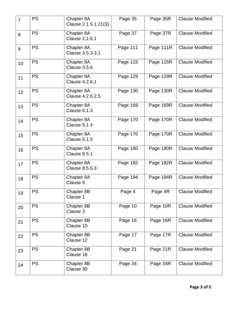
Page 3 of 5
7 PS Chapter 8A Clause 2.1.5.1.21(3)
Page 35 Page 35R Clause Modified
8 PS Chapter 8A Clause 2.1.6.1
Page 37 Page 37R Clause Modified
9 PS Chapter 8A Clause 3.5.3.3.1
Page 111 Page 111R Clause Modified
10 PS Chapter 8A Clause 3.5.6
Page 115 Page 115R Clause Modified
11 PS Chapter 8A Clause 4.2.6.1
Page 129 Page 129R Clause Modified
12 PS Chapter 8A Clause 4.2.6.2.5
Page 130 Page 130R Clause Modified
13 PS Chapter 8A Clause 5.1.3
Page 169 Page 169R Clause Modified
14 PS Chapter 8A Clause 5.1.4
Page 170 Page 170R Clause Modified
15 PS Chapter 8A Clause 5.1.5
Page 170 Page 170R Clause Modified
16 PS Chapter 8A Clause 8.5.1
Page 180 Page 180R Clause Modified
17 PS Chapter 8A Clause 8.5.6.3
Page 182 Page 182R Clause Modified
18 PS Chapter 8A Clause 9
Page 194 Page 194R Clause Modified
19 PS Chapter 8B Clause 1
Page 4 Page 4R Clause Modified
20 PS Chapter 8B Clause 3
Page 10 Page 10R Clause Modified
21 PS Chapter 8B Clause 10
Page 16 Page 16R Clause Modified
22 PS Chapter 8B Clause 12
Page 17 Page 17R Clause Modified
23 PS Chapter 8B Clause 16
Page 21 Page 21R Clause Modified
24 PS Chapter 8B Clause 30
Page 34 Page 34R Clause Modified

Page 4 of 5
25 PS Chapter 8B Clause 32
Page 36 Page 36R Clause Modified
26 PS Chapter 8B Clause 33
Page 36 Page 36R Clause Modified
27 PS Chapter 8B Clause 35
- Page 58 Added
28 PS Chapter 8B Clause 36
- Page 59 Added
29 PS Chapter 8B Clause 37
- Page 60 Added
30 PS Chapter 8B Clause 38
- Page 61 Added
31 PS Annexure-2 Scope of work for DLP
- - Added
S. No.
Document Clause No. /Page No.
In place of Please read as
Remarks
Volume-5 Tender Drawings
1. Tender Drawings
- - - 2 Nos. Drawings Added (RSS Sector 83 and RSS Sector 153)
S. No.
Document Clause No. /Page No.
In place of Please read as
Remarks
Volume-7 BOQ
1. BOQ Statement B12-Optional Items
Page 8of 47 Page 8Rof 47
Clause Modified
2. BOQ Statement B22-Optional Items
Page 9of 47 Page 9Rof 47
Clause Modified
3. BOQ Statement C- Key Dates
Page 12of 47 Page 12Rof 47
Key Dates Modified
4. BOQ Table-A Item No.2
Page 39of 47 Page 39Rof 47
Item Modified

Page 5 of 5
5. BOQ Table-A Item No.35 Page 44of 47 Page 44Rof 47
Added
6. BOQ Checklist of Vendor Approval
- Page 47Aof 47 to 47F of
47
Added
7.
BOQ Grand Total - - Row for Rebate Added
8. BOQ Appendix-C to Annexure-4 of ITT
- - Added
9 BOQ - - - BOQ in Pdf Format Added
BOQ in Excel Format Replaced

Contract: NE-02
DMRC/Contract NE-02/Vol-1/ITT Page 28R
of delay beyond the last date of issuing addendum given in NIT, the date of submission, at its
sole discretion may be extended by DMRC under Clause D-2.5 of ITT.
Without prejudice to the order of preference as specified in Clause 1.5 of General Conditions of
Contract, the provisions in such addenda shall take priority over the Invitation to Tender and
Tender Documents issued previously. Tenderers should acknowledge receipt of such addenda
and include them in the tender submittal. (In the format given in Appendix-10 of Form of Tender)
B4.2 The Tenderer should note that there might be aspects of his Tender and/or the evaluation
documents submitted with the Tender that will necessitate clarification. It is intended that any
aspect of the said evaluation documents and any amendments or clarification which are to have
contractual effect will be incorporated into the Contract either:
(a) by way of Special Conditions of Contract to be prepared by the Employer and agreed in writing
by the Tenderer prior to and conditional upon acceptance of the Tender; or
(b) by the Tenderer submitting, at the written request of the Employer, documents which are
expressly stated to form part of the Tender, whether requested before or after submission of the
documents forming part of the Tender, identified in para C2.3 (a) to C 2.3 ( i) below, and
whether as supplements to, or amended versions of such documents.
Save as aforesaid, all such amendments or clarifications shall not have contractual effect.
Requests for clarification and the tenderers responses shall be made in writing.
C. Preparation of Tenders
C1 Language
Tenders and all accompanying documents shall be in English. In case any accompanying
printed literature is in other languages, it shall be accompanied by an English translation. The
English version shall prevail in matters of interpretation.
C2. Documents Comprising the Tender
C2.1 The Tenderer shall, on or before the date and time given in the Notice of Invitation to Tender,
upload his Tender on e-tendering portal www.tenderwizard.com/DMRC in accordance with
the provision in Clause D-1.
Technical Package of this submission shall contain all the documents referred to in the
subsequent paragraphs C2.2 and C2.3 except pricing document as for Clause C2.2 (c).
Financial Package shall contain the documents referred to in paragraphs C2.2 (a); (b); (c).
C2.2 The Tenderer shall submit, as his Tender, the following documents, duly completed which in the
event of acceptance of the Tender, shall form part of the Contract:
(a) Form of Tender (Without appendices);
(b) Appendix 1 to the Form of Tender; Contract Conditions;

Contract: NE-02
DMRC/Contract NE-02/Vol-1/ITT Page 30R
tenderer shall not have any right to any claim on this account. The offer in pricing
document shall be given without considering any deviation in tender conditions.
Tenderers shall further note that except for deviations listed in Annexure 3 of Instructions
to Tenderer, the tender shall be deemed to comply with all the requirements in the tender
documents including Employer’s Requirements, without any extra cost to the Employer
irrespective of any mention to contrary, anywhere else in the Tender.
The tender price shall be added with the price of deviations given in “Statement of pricing for unqualified withdrawal of conditions/qualifications and deviations etc.”
with view of bringing various bidders at par, i.e. in full compliance of tender conditions;
(aa) Annexure 4 to ITT:– Requirement for Tender’s Technical Proposals
(a) Certificate of compliance
(b) Appendix A – Statement of Deviations
(c) Appendix B – Schedule of Sub-Contractor/ Vendors
(d) Appendix C – Pricing of Unqualified withdrawal of Conditions, Qualifications, Deviation, etc.
(e) Appendix D – Proposal for Equipment/Systems
(f) Appendix E – Undertaking for Transfer of technology
(g) Appendix F – Proforma for Submitting No Load Iron Losses and Full Load Copper Losses Figure
(h) Appendix G – Project Organisation
(i) Appendix H – Construction Machinery usage undertaking
(j) Appendix I – Sub- Contractor undertaking
(k) Appendix J – Interface requirement undertaking
(l) Appendix K – Scope of work compliance undertaking
(bb) Annexure 5 to ITT: – Tentative Project Implementation Programme (see paragraph
C8).
(cc) Annexure 6 to ITT: - Requirement of Tender Programme (see paragraph C8).
(dd) Annexure 7 to ITT: – Bank Guarantee for Tender Security (see paragraph C18).
(ee) Annexure 8 to ITT: – Confirmation of Performance Security Provider (see paragraph F5).
(ff) Annexure 9 to ITT:– Additional Bank Guarantee
(gg) Annexure 10 to ITT: – Details of Foreign Currency (see paragraph C16.1).
(hh) Annexure 11 to ITT: – Undertaking for Downloaded Tender Document
(ii) Annexure 12 to ITT: – Sample Format For Banking Reference for Liquidity
A declaration by the bidders as per Annexure -11 of ITT must be submitted stating that the tender document has been downloaded from official website of e-tendering portal www.tenderwizard.com/DMRC and no changes, what so ever, has been made by the bidder.

Contract: NE-02
DMRC/Contract NE-02/Vol-1/ITT Page 32R
(b) Value of the commitments and on-going works, on a yearly basis, to be
completed during the next 24 months from the first date of the tender
submission.
(c) Should be updated to price level as per 1.1.4 of NIT, by assuming 2% inflation
on foreign currency and 5% on Indian currency. For conversion of foreign
currency, please refer clause as per 1.1.4 of NIT.
C2.4 The Employer may get, from the Government, partial or complete waiver of taxes, royalties,
duties, cess, Octroi, and other levies payable to various authorities. The Contractor shall
maintain complete records of the amounts paid on these accounts and advise the Employer the
details with every bill. In case the waiver becomes effective, the Contractor will be advised on
the process to be followed to obtain the refund from the concerned authority. The Contractor
shall arrange for the remit of the refund to the Employer. In case of failure by the Contractor to
remit such amounts, the same shall be recovered from amounts due for payment to the
Contractor. With the tender submission, the tenderer shall submit the proof of U.P VAT
registration or shall submit an undertaking that he will get registered with U.P VAT authorities in
case of award of LOA to them.
C2.5 Tenderer shall quote all prices as per Clause 11.1.1 of GCC and Clause 24 of SCC.
C 2.6 Service tax: Refer as per the Clause 24 of SCC
C2.7 Unless stated otherwise in the tender documents, the contract shall be for the whole of the
Works as described in the tender documents, based on the unit rates and prices in the Bill of
Quantities submitted by the Tenderer.
C2.8 The Tenderer shall fill in rates and prices for all items of the works described in the Bill of
Quantities. Items against which no rates or price is entered by the Tenderer will not be paid for
by the Employer when executed and shall be deemed to be covered by the rates for other items
and prices in the Bill of Quantities.
C2.9 The employer shall deduct at source from the bills of the contractor any amount which employer
may require by law for deposition with the statutory authorities in India. The Employer shall
further furnish to the contractor a certificate for such tax deducted at source.
C2.10 The rate for each item shall be reasonable and not unbalanced.
C2.11 If the employer so decides, he may supply some items of Pricing Document to the contractor as
“Employer supply items” and in such an event the Contractor shall not be allowed to claim
payment for such items. The Employer shall notify a list of such items within three months of the
placement of the Contract.
C2.12 In exceptional circumstances, when it is proved beyond reasonable doubts that the Contractor
is not able to procure any equipment / material either locally or by import, as per the
specification given in the contract documents, the Employer may permit use of equipment/

Contract: NE-02
DMRC/Contract NE-02/Vol-1/ITT Page 49R
duplicate to the successful Tenderer, who will return one copy to the Employer duly acknowledged and signed by the
authorized signatory, within one week of receipt of the same by him.
F3.1(ii) The outcome/result of the tender shall be communicated to successful tenderers and will be posted on website..
F3.1(iii) After notification of award, if any unsuccessful tenderer requests in writing to DMRC asking reasons of being
unsuccessful, DMRC shall reply in writing giving brief reasons. Tenderers to note that no further correspondence on this
issue will be entertained by DMRC.
F3.2 The Letter of Acceptance will constitute a part of the contract.
F3.3 Upon “Letter of acceptance” being signed and returned by the successful Tenderer as per Clause F3.1, the employer
will promptly notify the unsuccessful Tenderers and discharge / return their tender securities.
F3.4 In the event of award of the Contract, the following will be the sequence of events in the order given below. The
Employer may seek suitable amendments to the Contract if such amendments are desired by the Employer.
(i) Approval by Competent Authority;
(ii) Letter of Acceptance and Notice to Proceed;
(iii) Signing of Contract;
(iv) Not Used.
F4 Signing of Agreement
The Tenderer should note that in the event of acceptance of the Tender, the Tenderer will be required to execute the
Contract Agreement in the form specified in Special Conditions of Contract with such modifications as may be
considered necessary at the time of finalisation of the contract within a period of 30 days of submission of Performance
Security or 60 days from the date of issue of the Letter of Acceptance whichever is later.
F5 Performance Security
F5.1 The Performance Security required in accordance with Clause 4.2 of the GCC shall be for 10% of the Contract Price
from the Scheduled commercial Bank (including Scheduled Commercial Foreign Banks) in India in the currency in
which the Contract Price is payable. The Performance Security shall be furnished to the Employer within 30 (thirty) days
of receipt of the Letter of Acceptance. The form of Performance Security provided in SCC.
The required Performance Security for the sum mentioned above may be submitted in any one of the following forms:
(a) Irrevocable bank guarantee in the prescribed format, given in Annexure-8 of Instruction to Tenderers (ITT), issued by a Scheduled Commercial Bank based in India or from a branch in India of a Scheduled foreign bank.
(b) Bank Draft in favour of Delhi Metro Rail Corporation Ltd. payable at New Delhi from a Scheduled Commercial Bank based in India.
(c) Fixed Deposit Receipt of a Scheduled Commercial bank / Post offices based in India duly pledged in favour of Delhi Metro Rail Corporation Ltd.
In case of joint venture/consortium, the Performance Security is to be submitted in the name of the JV / Consortium. However, splitting of the performance security (while ensuring the security is in the name of JV /
Consortium) and its submission by different members of the JV / Consortium for an amount proportionate to
their scope of work is also acceptable. The Performance Guarantee should be valid for a period of 6 (six) months beyond the Defect Liability Period.
F5.2 The Tenderer has to furnish other Guarantees, Undertakings, and Warranties, in accordance with the provisions of the
General Conditions of Contract and Special Conditions of Contract.

Contract: NE-02
DMRC/Contract NE-02/Vol-1/ITT Page 51R
CHECK SHEET FOR TECHNICAL SUBMMISION
Documents required to be submitted along with the Technical Package Annexure to ITT
Annexure Appendix to FORM OF TENDER ITT
S. No Annexure Description Submitted Submitted on Page no
Yes No
1. Annexure 1 Undertaking for Corrupt & Fraudulent Practice
2. Annexure 2 Copyright Undertaking
3. Annexure 3 Proforma for statement of minor deviations
4. Annexure 4 Requirements for Tenderer's Technical Proposals
5. Certificate of compliance
6. Appendix A - STATEMENT OF DEVIATIONS
7. Appendix B - Schedule of Sub-Contractors/ Vendors
8.
Appendix C – Pricing of unqualified withdrawal of
Conditions, Qualifications, Deviations, etc.
9. Appendix D - Proposal for equipments/systems
10. Appendix E - Undertaking for Transfer of Technology
11.
APPENDIX- F - Pro-forma for submitting No-load Iron
losses and Full Load Copper Losses figure
12. APPENDIX- G - PROJECT ORGANISATION
13.
APPENDIX- H - Construction Machinery usage
undertaking
14. APPENDIX- I - Sub Contractor Undertaking
15. APPENDIX- J - Interface requirement undertaking
16. Appendix – K – Scope of work compliance undertaking
17. Appendix L – Electrical Contractor License
18. Annexure 5 Tentative Project Implementation Programme
19. Annexure 6 Requirements for Tender Programme
20. Annexure 7 Form of Bank Guarantee for Tender Security
21
Annexure 8 Bank providing the PBG Form of Performance Bank Guarantee
To be submitted after award of Contract
22
Annexure 9 Form of Additional Bank Guarantee To be submitted after award of Contract
23 Annexure 10 Details of foreign currencies utilized in the bid
24 Annexure 11 Undertaking for Downloaded Tender Documents
Clause C2.4 Proof of UP VAT registration or Undertaking
Clause C7.3
Proposed terms and conditions upon which the Designer
shall be appointed.

Contract NE-02
DMRC/Contract NE-02/Vol-1/FOT Page 91R
APPENDIX-1A
SCHEDULE OF KEY DATES
All number refer from Commencement Dates of the works
Statement C - BRIEF DESCRIPTION OF key dates for SECTIONS RSS Tentative Date
for Award of LOA
Start of civil work
Start of submission of
vendor proposal for equipment drawing etc for approval
Completion of delivery of
major materials at
site like Transformers,
GIS bays, Incoming
Cables and control panels
Completion of Erection of
RSS equipment, EHV cabling and all civil engineering
works
Testing, commissionin
g and charging of both RSS
including EHV cabling
Integrated testing and Commissioning
KD 1 KD 2 KD 3 KD 4 KD 5 KD 6
S1 - Sector-83 Noida
30.09.15 31.03.16 26 weeks
30.05.16 35 weeks
31.01.17 70 weeks
30.04.17 83 weeks
30.06.17 91 weeks
30.09.2017 104 weeks
S2 - Sector-153 Noida
30.09.15 31.10.15 4 weeks
31.12.15 13 weeks
31.07.16 44 weeks
31.10.16 57 weeks
30.11.16 61 weeks
30.06.2017 91 weeks
Notes:-
These dates are sacrosanct and are to be strictly adhered to. The tenderer may fill the other milestone dates accordingly. The site will be available immediately after
issue of LOA.
Train trials are planned to start from 01.03.2017 for 20 KMs of section starting from Greater Noida end. Train trails for next 10 KMs to start from 01.08.2017
3. If the date of LOA varies due to some unforeseen reasons, other dates as mentioned above will advance/get postponed accordingly. However, the ROD date is Firm. ROD
date is 01.12.17
4. KM: 0 – Noida Sec-71
KM: 30 – Greater Noida Depot
Contract NE-02
DMRC/Contract NE-02/Vol-1/FOT Page 102R
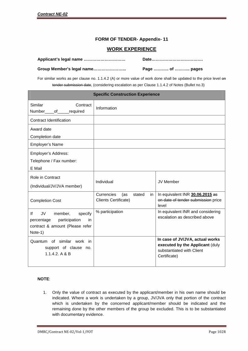
FORM OF TENDER- Appendix- 11
WORK EXPERIENCE
Applicant’s legal name ………………………… Date……………………………….
Group Member’s legal name…………………... Page ……….. of ……….. pages
For similar works as per clause no. 1.1.4.2 (A) or more value of work done shall be updated to the price level on
tender submission date, (considering escalation as per Clause 1.1.4.2 of Notes (Bullet no.3)
Specific Construction Experience
Similar Contract Number____of_____required Information
Contract Identification
Award date Completion date
Employer’s Name
Employer’s Address:
Telephone / Fax number:
E Mail
Role in Contract
(Individual/JV/JVA member) Individual JV Member
Completion Cost Currencies (as stated in Clients Certificate)
In equivalent INR 30.06.2015 as on date of tender submission price level
If JV member, specify percentage participation in contract & amount (Please refer Note-1)
% participation
In equivalent INR and considering escalation as described above
Quantum of similar work in support of clause no. 1.1.4.2. A & B
In case of JV/JVA, actual works executed by the Applicant (duly substantiated with Client Certificate)
NOTE:
1. Only the value of contract as executed by the applicant/member in his own name should be indicated. Where a work is undertaken by a group, JV/JVA only that portion of the contract which is undertaken by the concerned applicant/member should be indicated and the remaining done by the other members of the group be excluded. This is to be substantiated with documentary evidence.

Contract NE-02
DMRC/Contract NE-02/Vol-1/FOT Page 103R
2. Separate sheet for each work along with Clients Certificate to be submitted.
FORM OF TENDER- Appendix- 12
Summary of Information provided in Appendix-11
Applicant’s legal name …………………………....... Date……………………………….
Group Member’s legal name………………………… Page ……….. of ……….. pages
NOTE:-
1. In case the work was done as JV/JVA, only the value of work done by the applicant as per his
Percentage participation must be given.
2. Reasons of delay whether on contractors account or on account of Employer in each
applicable case need to be enclosed separately.
Name of Applicant (each member in case of group, JV/JVA)
Total Number of works
as per clause no. 1.1.4.2 A at the price level of 30.06.2015 as on date of tender submission
No. of contracts delayed, i.e., completed beyond the original date of completion
Contract NE-02
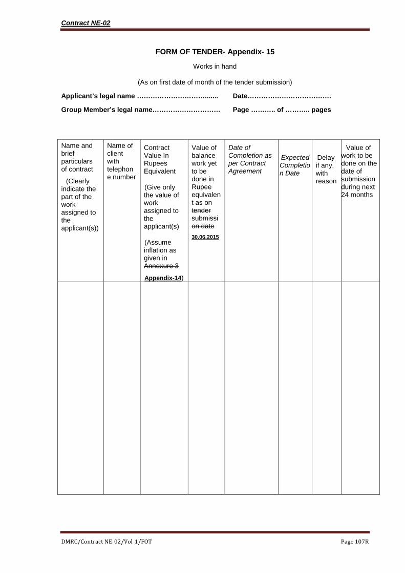
DMRC/Contract NE-02/Vol-1/FOT Page 107R
FORM OF TENDER- Appendix- 15
Works in hand
(As on first date of month of the tender submission)
Applicant’s legal name …………………………....... Date……………………………….
Group Member’s legal name………………………… Page ……….. of ……….. pages
Name and brief particulars of contract
(Clearly indicate the part of the work assigned to the applicant(s))
Name of client with telephone number
Contract Value In Rupees Equivalent
(Give only the value of work assigned to the applicant(s)
(Assume inflation as given in Annexure 3
Appendix-14)
Value of balance work yet to be done in Rupee equivalent as on tender submission date 30.06.2015
Date of Completion as per Contract Agreement
Expected Completion Date
Delay if any, with reason
Value of work to be done on the date of submission during next 24 months

Contract NE02 Special Conditions of Contract
Page 21R of 28
The variations can be implemented anywhere in the network of DMRC.
Sub Clause 12.5 (g) For Non-JICA portion of work while deriving the prices ED/CD, CST & output VAT will be considered for payment.
36. Sub-Clause 13.3.4 Payment on Termination and/or Optional Termination due to
Force Majeure
Following is added after (e) in clause 13.3.4 of GCC
For the ease of determination of the cost to be paid to the Contractor, a lump sum payment equal to 2% (two percent) of the value of the work remaining incomplete on the date of Termination notice taking effect shall be paid in place of payments as per sub-clause 13.3.4 ( c), (d) & ( e) (a),(b)&(c).
37. Sub-Clause 14.1 Indemnity
The last Para of Clause 14.1 of GCC shall not be applicable in this contract and the Contractor shall include such risks also in his insurance cover.
38. Sub-Clause 16.7 Optional Termination, Payment and Release
Instead of the period of continuous 84 days or multiple of 140 days mentioned in GCC, this optional termination shall be applicable only when the work is prevented for a continuous period of 120 days.
39. Sub-Clause 17.7 Conciliation Procedure
Clause 17.7 of GCC is superseded and replaced as under:
For the purpose of conciliation in this contract, the conciliation shall be undertaken by one conciliator selected from panel of conciliators maintained by the employer, who shall be from serving or retired engineers of Government Departments, or of Public Sector Undertakings. Out of this panel, a list of three Conciliators shall be sent to the Contractor who shall choose one of them to act as Conciliator and conduct conciliation proceedings in accordance with “The Arbitration and Conciliation Act, 1996”, of India.
The Employer and the Contractor shall in good faith co-operate with the Conciliator and, in particular, shall endeavour to comply with requests by the Conciliator to submit written materials, provide evidence and attend meetings. Each party may, on his own initiative or at the invitation of the Conciliator, submit to the Conciliator suggestions for the settlement of the dispute.
When it appears to the Conciliator that there exist elements of a

Contract NE02 Special Conditions of Contract
Page 28A of 28
61. Additional Clause Comprehensive Annual Maintenance
Comprehensive Annual Maintenance Contract Rates for One to Eight Years after Completion of 2 Years Defects Liability Period have been asked in Bill of Quantities (Optional Items) subject to the following Conditions:-
1. Bill of Quantities (Optional) Items & Rates Mentioned therein shall be Part of Tender Evaluation for this Contract.
2. It will not be binding on the Employer to enter into any kind of Annual Maintenance Contract any time prior to Completion of Contract or prior to Completion of Defects Liability Period or after Defects Liability Period.
3. If Employer decides to enter into Comprehensive Annual Maintenance Contract for any Item or for any combination of Items as mentioned in Bill of Quantities (Optional Items), a Separate Contract Agreement shall be made which will not be part of this contract.
4. The rates of AMC of fourth year and onwards shall be decided based on the rates of AMC quoted for the third year as per the IEEMA formula mentioned provided as Schedule-10 to SCC.
5. Rates are to be inclusive of All Taxes & Duties including, Delhi / UP / Haryana VAT.
6. The rates shall also be inclusive of providing and maintaining adequate stock of spares so as to promptly fulfil his obligations during the Annual Maintenance period as laid down in Employer's Requirements.
7. The Contractor shall provide Experts and their team for Maintenance during the Annual Maintenance period and the rates for the same shall be included in the quoted price.
8. All Terms & Conditions in this Tender document shall also be applicable for Comprehensive Annual Maintenance Contract.

Special Conditions of Contract – Schedules-2
Confidential Page 1R of 3
DELHI METRO RAIL CORPORATION LIMITED
SPECIAL CONDITIONS OF CONTRACT
SCHEDULE - 2
PERFORMANCE SECURITY
Deleted
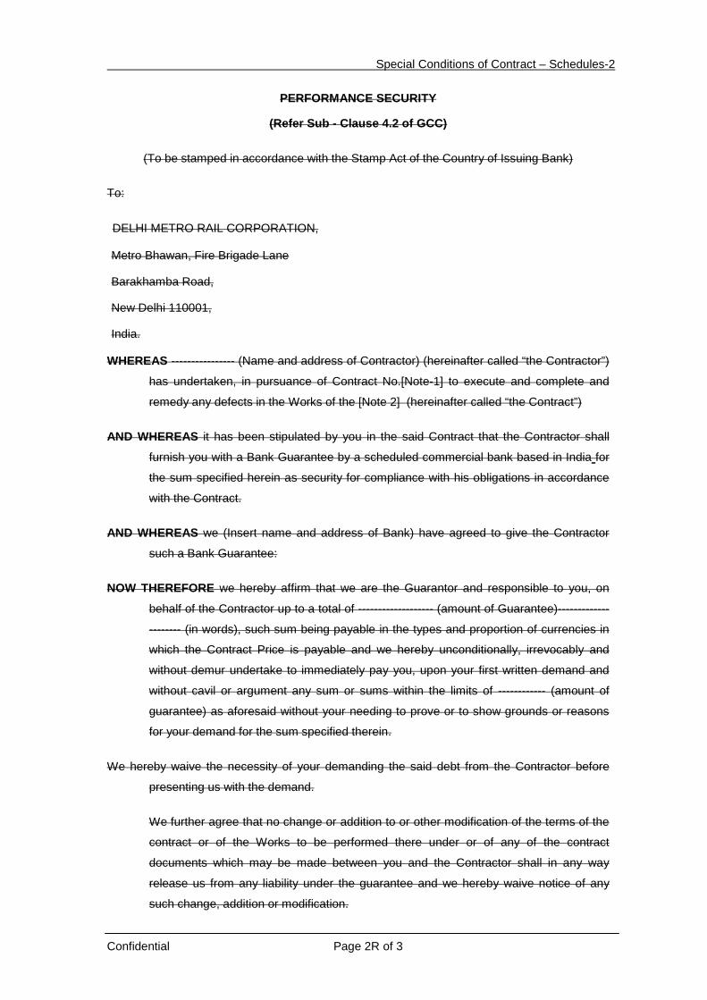
Special Conditions of Contract – Schedules-2
Confidential Page 2R of 3
PERFORMANCE SECURITY
(Refer Sub - Clause 4.2 of GCC)
(To be stamped in accordance with the Stamp Act of the Country of Issuing Bank)
To:
DELHI METRO RAIL CORPORATION,
Metro Bhawan, Fire Brigade Lane
Barakhamba Road,
New Delhi 110001,
India.
WHEREAS ---------------- (Name and address of Contractor) (hereinafter called “the Contractor”)
has undertaken, in pursuance of Contract No.[Note-1] to execute and complete and
remedy any defects in the Works of the [Note 2] (hereinafter called “the Contract”)
AND WHEREAS it has been stipulated by you in the said Contract that the Contractor shall
furnish you with a Bank Guarantee by a scheduled commercial bank based in India for
the sum specified herein as security for compliance with his obligations in accordance
with the Contract.
AND WHEREAS we (Insert name and address of Bank) have agreed to give the Contractor
such a Bank Guarantee:
NOW THEREFORE we hereby affirm that we are the Guarantor and responsible to you, on
behalf of the Contractor up to a total of ------------------- (amount of Guarantee)-------------
-------- (in words), such sum being payable in the types and proportion of currencies in
which the Contract Price is payable and we hereby unconditionally, irrevocably and
without demur undertake to immediately pay you, upon your first written demand and
without cavil or argument any sum or sums within the limits of ------------ (amount of
guarantee) as aforesaid without your needing to prove or to show grounds or reasons
for your demand for the sum specified therein.
We hereby waive the necessity of your demanding the said debt from the Contractor before
presenting us with the demand.
We further agree that no change or addition to or other modification of the terms of the
contract or of the Works to be performed there under or of any of the contract
documents which may be made between you and the Contractor shall in any way
release us from any liability under the guarantee and we hereby waive notice of any
such change, addition or modification.

Special Conditions of Contract – Schedules-2
Confidential Page 3R of 3
This guarantee shall be valid for 28 days beyond the Defect Liability Period. The pendency of
any dispute or arbitration or other proceedings shall not affect this guarantee in any
manner.
SIGNATURE AND SEAL OF THE GUARANTOR
----------------------------------------------------------------
NAME OF BANK -----------------------------------------
ADDRESS --------------------------------------------------
DATE -------------------------------------------------------
Notes:
1. Enter Contract Number
2. Enter Name of the contract
3. The stamp papers of appropriate value shall be purchased in the name of the
Bank, who issues the ‘Bank Guarantee’

DELHI METRO RAIL CORPORATION LTD.
Design, Detail Engineering, Supply, Installation, Testing and Commissioning, 132 kV receiving cum 25 kV AC Traction cum 33 kV Auxiliary Main Sub Stations and EHV cabling for Noida-Greater Noida Corridors of Delhi Mass Rapid Transport System Project Phase-3
CONTRACT: NE-02
TENDER DOCUMENTS
VOLUME 3
GENERAL SPECIFICATION
Delhi Metro Rail Corporation Limited Metro Bhawan, Fire Brigade Lane,
Barakhamba Road, New Delhi-110001

NE-02 Electrical Contracts - General Specification
Page GS I Table of Contents
TABLE OF CONTENTS Volume 3
1. GENERAL ......................................................................................................... 1
1.1 Application of the General Specification (GS) ........................................................................................ 1
1.2 Abbreviations ............................................................................................................................................ 1
1.3 Definitions .................................................................................................................................................. 3
1.4 Glossary of Terms ..................................................................................................................................... 5
1.5 Submission for Review .............................................................................................................................. 5
1.6 Standards, Codes of Practice ................................................................................................................... 6
1.7 Employer’s Drawings ............................................................................................................................... 6
1.8 Specifications in Metric and Imperial Units ........................................................................................... 7
1.9 System Safety ............................................................................................................................................. 7
1.10 Not used ..................................................................................................................................................... 8
1.11 Suitability for Purpose .............................................................................................................................. 8
1.12 Climatic Condition / Operating Environment ........................................................................................ 8
1.13 Survey and Site Investigations ............................................................................................................... 12
2. PLANNING, PROGRAMME AND PROGRESS MONITORING ....................... 1
2.1 Planning ..................................................................................................................................................... 1
2.2 Programming General Requirements ..................................................................................................... 1
2.3 Progress Monitoring ................................................................................................................................. 1
2.4 Works Programme .................................................................................................................................... 2
2.5 Submission Programme ............................................................................................................................ 5
2.6 Procurement and Manufacturing Programme ....................................................................................... 5
2.7 Installation Programme ............................................................................................................................ 7
2.8 Testing and Commissioning Programme ................................................................................................ 8
2.9 Training and Transfer of Technology Programme ................................................................................ 8
2.10 Not used ..................................................................................................................................................... 9
2.11 Not used ..................................................................................................................................................... 9
2.12 Time Chainage Programme (T/C) ........................................................................................................... 9
2.13 Track Related Installation Programme (TRIP) ..................................................................................... 9
2.14 Programme Submissions .......................................................................................................................... 9
2.15 Programme Review ................................................................................................................................. 10

NE-02 Electrical Contracts - General Specification
Page GS II Table of Contents
2.16 Works Programme Revisions ................................................................................................................ 10
2.17 Monthly Progress Report ....................................................................................................................... 10
2.18 Programme Analysis Report ................................................................................................................. 11
2.19 Key Date and Access Date Report ........................................................................................................ 11
2.20 Not used ................................................................................................................................................... 12
2.21 Progress Meetings ................................................................................................................................... 12
2.22 Quarterly Review Meetings ................................................................................................................... 12
3. MANAGEMENT PLANS AND SUBMISSIONS ................................................. 1
3.1 General ...................................................................................................................................................... 1
3.2 General Organisation ............................................................................................................................... 1
3.3 Project Management Plan ....................................................................................................................... 2
3.4 Systems Assurance Plans ......................................................................................................................... 5
3.5 Procurement and Manufacturing Plan ................................................................................................... 6
3.6 Construction and Installation Management Plan .................................................................................. 9
3.7 Deleted ..................................................................................................................................................... 11
4. DOCUMENTS SUBMISSION AND REVIEW .................................................... 1
4.1 Documents, Submissions and Correspondence ...................................................................................... 1
4.2 Submissions to the Employer’s Representative ..................................................................................... 1
4.3 Records and Reports ................................................................................................................................ 2
4.4 Records ...................................................................................................................................................... 5
5. QUALITY MANAGEMENT ................................................................................ 1
5.1 Introduction .............................................................................................................................................. 1
5.2 General Requirements ...................................................................................................................................... 1
5.3 Management Quality Plan ................................................................................................................................ 3
5.4 Not used .............................................................................................................................................................. 3
5.5 Site Quality Plan ................................................................................................................................................ 3
5.6 Inspection and Test Plans, Records and Reports ........................................................................................... 4
5.7 Review, Verification & Audit ........................................................................................................................... 5
5.8 Quality Control Register .................................................................................................................................. 6
5.9 Summaries of Inspection and/or Test .............................................................................................................. 6
5.10 Notification of Non-conformities ...................................................................................................................... 6
6. SOFTWARE MANAGEMENT AND CONTROL .................................................... 1

NE-02 Electrical Contracts - General Specification
Page GS III Table of Contents
6.1 Prescriptive Framework ........................................................................................................................... 1
6.2 Software Framework ................................................................................................................................ 1
7. MATERIALS AND EQUIPMENT ...................................................................... 1
7.1 Materials and Equipment Provided by the Employer ........................................................................... 1
7.2 Materials .................................................................................................................................................... 1
7.3 Equipment ................................................................................................................................................. 3
7.4 Electronic Control Racks & Cabinets ..................................................................................................... 3
8. PACKAGING, STORAGE, SHIPPING AND DELIVERY .................................. 1
8.1 Storage of Equipment ............................................................................................................................... 1
8.2 Crating ....................................................................................................................................................... 1
8.3 General Precautions .................................................................................................................................. 1
8.4 Packaging Procedures ............................................................................................................................... 2
8.5 Shipping ..................................................................................................................................................... 2
8.6 Delivery ...................................................................................................................................................... 3
9. TESTING AND COMMISSIONING ................................................................... 1
9.1 General ....................................................................................................................................................... 1
9.2 Manufacturing Test Plan .......................................................................................................................... 1
9.3 Commissioning Plan ................................................................................................................................. 3
9.4 On-Site Testing and Commissioning Plan .............................................................................................. 4
9.5 Activity of the Employer and the Employer’s Representative ............................................................ 10
9.6 Records and Reports ............................................................................................................................... 10
9.7 Test Equipment and Facilities ................................................................................................................ 12
9.8 Witnessing by the Employer and the Employer’s Representative ...................................................... 13
9.9 Failures .................................................................................................................................................... 14
9.10 Repeat Tests ............................................................................................................................................. 14
9.11 Fault Categories ...................................................................................................................................... 15
9.12 Fault Log .................................................................................................................................................. 15
9.13 Hardware Failure Reports ..................................................................................................................... 15
9.14 Software Failure Reports ....................................................................................................................... 15
10. TRAINING ......................................................................................................... 1
10.1 Training Requirements ............................................................................................................................. 1

NE-02 Electrical Contracts - General Specification
Page GS IV Table of Contents
10.2 Training Method....................................................................................................................................... 2
10.3 Employer’s Instructor Training .............................................................................................................. 4
10.4 Training Plant & Equipment .................................................................................................................. 4
10.5 Testing and Assessment ........................................................................................................................... 5
10.6 Training Records ...................................................................................................................................... 5
10.7 Transfer of Technology ..................................................................................................................... ..10-4
11. OPERATION AND MAINTENANCE DOCUMENTATION ................................ 1
11.1 General ...................................................................................................................................................... 1
11.2 Arrangement and Format of Manuals .................................................................................................... 2
11.3 Drawings ................................................................................................................................................... 3
11.4 Submissions ............................................................................................................................................... 3
11.5 Operation and Maintenance Manuals .................................................................................................... 4
12. SUPERVISION AND PLANNING OF MAINTENANCE .................................... 1
12.1 Scope .......................................................................................................................................................... 1
12.2 Maintenance Planning & Management Staff ......................................................................................... 1
12.3 Supervisory Staff ...................................................................................................................................... 2
13. SUPPLY OF SPARE PARTS, SPECIAL TOOLS AND TEST EQUIPMENT .... 1
13.1 Details of supply........................................................................................................................................ 1
13.2 Manufacture and delivery of Spare Parts .............................................................................................. 3
13.3 Contract Spares ........................................................................................................................................ 4
13.4 Commissioning Spares ............................................................................................................................. 4
13.5 Defects Liability Spares ........................................................................................................................... 5
13.6 Special Tools and Test Equipment .......................................................................................................... 5
13.7 Coding and Tagging of Spare Parts and Special Tools and Test Equipment...................................... 6
14. THE WORKS AND CARE OF THE WORKS .................................................... 1
14.1 Methods of Construction ......................................................................................................................... 1
14.2 Temporary Works .................................................................................................................................... 1
14.3 Normal Working Hours ........................................................................................................................... 1
14.4 Drawings and Schedules .......................................................................................................................... 1
14.5 Notification and Inspection of Works ..................................................................................................... 1
14.6 Construction Restraints ............................................................................................................................ 2
NE-02 Electrical Contracts - General Specification
Page GS V Table of Contents
14.7 Protection from Water .............................................................................................................................. 2
14.8 Protection from Weather .......................................................................................................................... 2
14.9 Protection of Work.................................................................................................................................... 2
15. SITE ESTABLISHMENT AND ATTENDANCE................................................. 1
15.1 Use of the Site ............................................................................................................................................ 1
15.2 Survey of the Site....................................................................................................................................... 1
15.3 Fences and Signs on the Site ..................................................................................................................... 1
15.4 The Contractor’s Site Accommodation ................................................................................................... 2
15.5 Site Utilities and Access ............................................................................................................................ 2
15.6 Site Facilities for the Employer’s Representative .................................................................................. 3
15.7 Clearance of the Site ................................................................................................................................. 3
15.8 Attendance ................................................................................................................................................. 4
15.9 Contractor’s Equipment ........................................................................................................................... 5
15.10 Security .................................................................................................................................................. 5
16. LIAISON WITH OTHERS .................................................................................. 1
16.1 Liaison with Others ................................................................................................................................... 1
16.2 Work by Other Contractors ..................................................................................................................... 1
16.3 Interface Management .............................................................................................................................. 1
17. THE SITE .......................................................................................................... 1
17.1 Access to Site ............................................................................................................................................. 1
17.2 Site Restrictions ......................................................................................................................................... 1
17.3 Site Services ............................................................................................................................................... 2
17.4 Site Cleanliness .......................................................................................................................................... 2
17.5 Prevention of Mosquito Breeding ............................................................................................................ 3
17.6 Deleted ........................................................................................................................................................ 3
17.7 Deleted ........................................................................................................................................................ 3
17.8 Deleted ........................................................................................................................................................ 3
17.9 Access to the Site by Other Contractors ................................................................................................. 3
17.10 Transportation to Site ........................................................................................................................... 4
17.11 Contractor’s Own Rolling Stock .......................................................................................................... 5
17.12 Defined Area Working and Works Train Operations ....................................................................... 6

NE-02 Electrical Contracts - General Specification
Page GS VI Table of Contents
17.13 Not used ................................................................................................................................................. 6
18. HEALTH AND SAFETY .................................................................................... 1
18.1 Health and Safety Philosophy .................................................................................................................. 1
18.2 Health and Safety Management .............................................................................................................. 1
18.3 Legislation, Codes of Practice, Standards, etc. ...................................................................................... 2
18.4 Breach of Health and Safety Obligations ............................................................................................... 2
18.5 Contractor’s Health and Safety Documentation ................................................................................... 2
18.6 Contractor’s Safety Arrangements ......................................................................................................... 3
18.7 Site Conditions .......................................................................................................................................... 7
19. DAMAGE AND INTERFERENCE ..................................................................... 1
19.1 Damage and Interference ......................................................................................................................... 1
19.2 Watercourses and Drainage Systems ...................................................................................................... 2
19.3 Utilities....................................................................................................................................................... 3
19.4 Structures, Roads and Other Property ................................................................................................... 6
19.5 Access......................................................................................................................................................... 8
19.6 Trees and Other Similar Obstructions ................................................................................................... 8
19.7 Noise Control on Works Site ................................................................................................................... 8
19.8 Spoil Disposal ............................................................................................................................................ 9
20. ENVIRONMENTAL PROTECTION REQUIREMENTS ..................................... 1
20.1 GENERAL ................................................................................................................................................ 1
20.2 AVOIDANCE OF NUISANCE ............................................................................................................... 2
20.3 AIR QUALITY ......................................................................................................................................... 3
20.4 WATER QUALITY ................................................................................................................................. 5
20.5 NOISE ....................................................................................................................................................... 6
20.6 WASTE ..................................................................................................................................................... 8
20.7 PREVENTION OF MOSQUITO BREEDING ..................................................................................... 8
21. PHOTOGRAPHS .............................................................................................. 1
21.1 Photographs .............................................................................................................................................. 1
22 TEMPORARY ELECTRICITY SUPPLY ............................................................ 1
22.1 Electricity Supply for the Contractor by the Project Civil Contractors.............................................. 1
22.2 Applicability .............................................................................................................................................. 1

NE-02 Electrical Contracts - General Specification
Page GS VII Table of Contents
22.3 Work on Site .............................................................................................................................................. 1
22.4 Electrical General ..................................................................................................................................... 2
22.5 Materials, Appliances and Components .................................................................................................. 2
22.6 Mains Voltage ............................................................................................................................................ 2
22.7 Types of Distribution Supply ................................................................................................................... 2
22.8 Protection of Circuits ................................................................................................................................ 3
22.9 Earthing ..................................................................................................................................................... 3
22.10 Plugs, Socket Outlets and Couplers ..................................................................................................... 3
22.11 Cables ..................................................................................................................................................... 4
22.12 Lighting Installation ............................................................................................................................. 5
22.13 Electrical Motors ................................................................................................................................... 5
22.14 Inspection and Testing .......................................................................................................................... 5
22.15 Identification ......................................................................................................................................... 5
22.16 Maintenance .......................................................................................................................................... 5
22.17 Maintenance Record ............................................................................................................................. 6
22.18 Metering ................................................................................................................................................. 6
22.19 Inability to Supply ................................................................................................................................. 6
23 NOT USED ........................................................................................................ 1 APPENDIX-1
MONTHLY PROGRESS REPORT ............................................................................ 1
1.1 Topics ......................................................................................................................................................... 1
1.2 Progress Reports ....................................................................................................................................... 1
1.3 Copies ......................................................................................................................................................... 2 APPENDIX-2
NOT USED ................................................................................................................. 1 APPENDIX-3
SUBMISSION FOR REVIEW REQUEST FORM ....................................................... 1 APPENDIX-4
SCHEDULE OF ITEMS TO BE SUBMITTED BY CONTRACTOR............................ 1 APPENDIX-5
TYPICAL TYPE TEST REQUIREMENTS

NE-02 Electrical Contracts - General Specification
Page GS VIII Table of Contents
5.1 Electronic and Electrical Equipment ...................................................................................................... 1
5.2 Mechanical Tests ...................................................................................................................................... 2
5.3 Environmental Tests ................................................................................................................................ 5
5.4 Electrical Tests .......................................................................................................................................... 7 APPENDIX-6
REQUEST FOR INSPECTION OF WORKS FORM ................................................... 1 APPENDIX-7
NOT USED ................................................................................................................. 1 APPENDIX-8
FIRST AID REQUIREMENTS .................................................................................... 1
8.1 Provisions by others ................................................................................................................................. 1
8.2 Provisions by the Contractor ................................................................................................................... 1 APPENDIX-9
WORKS AREAS
9.1 Works Areas ............................................................................................................................................. 1
End of Table of Contents

NE-02 Electrical Contracts - General Specification
Page GS IX Table of Contents
Page Intentionally Blank


NE-02 Electrical Contracts - General Specification
Page GS 1 of 12
CHAPTER 1
1 GENERAL 1.1 Application of the General Specification (GS)
1.1.1 The provisions contained in the Particular Specification (PS) and the Employer’s Drawings shall prevail over the provisions contained in this GS.
1.1.1 The provisions contained in the GS shall prevail over the provisions contained in International Standards, European Standards, British Standards, Indian Standards, British Standard Codes of Practice and similar standard documents stated in the Contract.
1.1.2 This GS shall be read in conjunction with the other documents constituting the Contract.
1.2 Abbreviations Common abbreviations used in the GS and in the PSs shall have the following meanings:
ACB : Air Circuit Breaker
AMS : Auxiliary Main Sub Station
ASS : Auxiliary Sub Station
BCC : Backup Control Centre
BCU : Bay Control Unit
BS : British Standard
BEC : Buried Earth Conductor
BMS : Building Management System
CADD : Computer Aided Design and Drafting
CAR : Corrective Action Request
CMV : Catenary Maintenance Vehicle
CNP : Construction Noise Permits
COTS : Commercial Off the Shelf
CPM : Critical Path Method
CV : Curriculum Vitae
DG : Diesel Generator
DLP : Defects Liability Period
DMRC
: Delhi Metro Rail Corporation
ECS : Environment Control System

NE-02 Electrical Contracts - General Specification
Page GS 2 of 12
E&M : Electrical & Mechanical
EMC : Electromagnetic Compatibility
EMIP : Environmental Mitigation Implementation Plan
EMP : Environmental Management Plan
EMSD : Electrical and Mechanical Services Department
EMU : Electric Multiple Unit
EN : Euro-Norm (European Standards)
EPD : Environmental Protection Department
ETI : Employer's Training Instructors
FAI : First Article Inspection
FAT : Factory Acceptance Test(s)
GCC : General Conditions of Contract
GS : General Specification (this document)
HV : High Voltage
IEC : International Electro-technical Commission
IEE : The Institution of Electrical Engineers
IED : Intelligent Electronic Device
IP : Ingress Protection
IS : Indian Standards
ISO : International Standards Organisation
ITT : Instructions To Tenderers
ITU : International Telecommunications Union
LV : Low Voltage
MCB : Miniature Circuit Breaker
MMI/ HMI : Man/Human -Machine Interface
MTR : Mass Transit Railway
NSR : Noise Sensitive Receivers
OCC : Operations Control Centre
OPC : Overhead Protection Cable
OSR : Operational Safety Report
OSR(S) : Operational Safety Report (Software)
OHE : Overhead Equipment (Flexible Catenary)
P3 : Primavera Project Planner
PLC : Programmable Logic Controller

NE-02 Electrical Contracts - General Specification
Page GS 3 of 12
PPE : Personal Protective Equipment
PS/TS : Particular Specification
PVC : Polyvinyl Chloride
QA : Quality Assurance
RAMS : Reliability, Availability, Maintainability and Safety
RC : Return Conductor Cable
ROCS : Rigid Overhead Conductor System
RSS : Receiving Sub Station
RTU : Remote Terminal Unit
SAR : Special Administrative Region
SAT : Systems Acceptance Test(s)
SCADA : Supervisory Control and Data Acquisition System
SCC : Special Conditions of Contract
SIL : Safety Integrity Level
SQAP
: Software Quality Assurance Plan
SRR : Submission Review Request
SWA : Steel Wire Armoured
T/C : Time Chainage
TRIP : Track Related Installation Programme
TSS : Traction Sub Station
TVS : Tunnel Ventilation System
UPS : Uninterrupted Power Supply
Table 1-1 General Abbreviations
1.2.1 Further abbreviations may be defined within the body of the GS or PS where there is only local applicability. Where such abbreviations exist the Contractor shall exercise great care that the abbreviation is not used out of context when communicating with the Employer, the Employer’s Representative or any Third Party.
1.2.2 Abbreviations of units of measurement used in the GS shall have the meanings as defined under the SI system of units.
1.3 Definitions Words and phrases defined in the GCC or SCC shall retain the same meaning within the GS and PS unless specifically redefined within this GS or under the provisions of clause 0 above for the purpose of a particular clause or group of clauses. (1) “Access Dates” are dates that are to be achieved by other than the
Contractor and which are considered to be essential to the successful completion of the Contract to the original planned schedule. A list of the activities completion of which are considered to give rise to an Access Date are included in the FOT. ( To be checked about access dates )

NE-02 Electrical Contracts - General Specification
Page GS 4 of 12
(2) “Commissioning” means the process of setting to work the complete transportation system through a series of integrated tests that demonstrate the installation and performance in accordance with the specified criteria.
(3) “Day” means calendar day unless expressly stated otherwise.
(4) “Defined Area” means an area within which Works Trains will be operated and the Employer’s defined area working safety rules will apply.
(5) “Factory Acceptance Tests” means the tests to be performed at the Contractor’s factories prior to delivery to the Site to verify compliance with the Specification and quality standards
(6) “Installation Tests” means the tests to be performed to verify the conformity of completion of an installation/assembly to the design documents previously reviewed without objection by the Employers Representative prior to the start of Commissioning. Installation Tests do not form part of the Tests on Completion to be performed by the Contractor in order to achieve Employer’s Taking Over of the Works or any Section however they must be successfully completed before the Tests on Completion can commence.
(7) “Key Dates” are dates which are to be achieved by the Contractor and which are considered to be essential to the successful completion of the project to the original planned schedule. A list of the activities, completion of which gives rise to a Key Date, is included in the FOT.
(8) “Partial Acceptance Tests” means the functional tests to be performed on components and parts of systems to meet the specified criteria. Partial Acceptance Tests form part of the Tests on Completion to be performed under the Contract in order to achieve Employer’s Taking Over of the Works or any Section.
(9) “Service Trial” means the phase after completion of the System Acceptance Tests where the training and operating procedures are validated through the running of the trains to the published timetable. Service Trial form part of the Tests on Completion to be performed under the Contract in order to achieve Employer’s Taking Over of the Works or any Section.
(10) “Quality Control Point” means a point in time when a notice or other document is to be submitted to the Employer’s Representative in accordance with the Contract before the Contractor can commence, proceed with or terminate an activity
(11) “Quality Hold Point” means a point in time when a notice of no objection by the Employer’s Representative is required.
(12) ‘S’ curve” means the graphical relationship between the planned (and actual where appropriate) quantity of completed work (or resources) and time. The curve produced is to be illustrated on an accumulative basis where the slope of the line indicates the rate of undertaking the work or rate of expenditure of the resources.
(13) “Specification (the)” means the aggregate sum of the documents and any amendments thereto, issued to Tenderers by DMRC as part of the Tender process before the final date for submission of Tenders. This shall include but not be limited to; Employer’s

NE-02 Electrical Contracts - General Specification
Page GS 5 of 12
Requirements, Employer’s Tender Drawings, Preliminary Operating Plan and Clarification of Tender Documents issued in accordance with the ITT but shall not include the ITT itself nor any minutes of meetings.
(14) “Specification (this)” means the particular document within which the reference is made.
(15) “System Acceptance Tests” means those tests that demonstrate the performance of the installation/equipment to the specified requirements as detailed in the PS. SATs form part of the Tests on Completion to be performed under the Contract in order to achieve Employer’s Taking Over of the Works or any Section.
(16) “Integrated Testing and Commissioning” means those tests that demonstrate the integration of the complete transport system meeting the requirements of the Specification in an operating environment. Integrated Testing and Commissioning form part of the Tests on Completion to be performed by the Contractor in order to achieve Employer’s Taking Over of the Works or any Section.
(17) “Validation” means the process of confirmation by examination and provision of objective evidence that the application produced achieves the particular requirements specified.
(18) “Verification” means the process of confirmation by examination and provision of objective evidence that the specified requirements have been incorporated.
1.4 Glossary of Terms
1.4.1 Words and expressions to which meanings are assigned in any paragraph of the GS shall have the same meanings in other paragraphs of the GS except when the context otherwise requires.
1.4.2 Utilities are electricity, lighting, traffic control, telephone and other communication cables, gas, water, sewage and drainage pipes and ducts, including all associated protection, supports, ancillary structures, fittings and equipment.
1.5 Submission for Review
1.5.1 Reference in the GS and PS to any submission made by the Contractor to the Employer’s Representative having been reviewed without objection by the Employer’s Representative shall mean the issue of a notice of no objection by the Employer’s Representative issued in response to a submission made by the Contractor. Documents, drawings, specifications, calculations, technical papers, material samples, methods of construction and any other matters which have been reviewed without objection by the Employer’s Representative shall not be changed without further submission for review to the Employer’s Representative of the proposed changes.

NE-02 Electrical Contracts - General Specification
Page GS 6 of 12
1.5.2 Clause 4.2 below prescribes the process to be adopted for submissions of documents, material samples and any other items to the Employer’s Representative. Schedules of items that are to be submitted to the Employer’s Representative for review are contained within this GS and/or the PS.
1.5.3 Submissions for review shall be made in accordance with the dates (relative to the Works Programme) stated in the GS and/or the PS, or in accordance with APPENDIX 4 of this Specification. For items not specifically given a submission date in the Specification submissions shall be strictly in accordance with the agreed Submissions Programme or as directed by the Employer’s Representative.
1.6 Standards, Codes of Practice
1.6.1 Unless otherwise stated in the Contract, reference in the GS to International Standards, European Standards, British Standards, British Standard Codes of Practice and similar standards shall be to that edition of the document stated in the PS, including all latest amendments issued by the relevant authority. In the event that no specific edition reference is given, the current edition as at the date of issue of the Letter of Acceptance shall apply.
1.6.2 Later editions of International Standards, European Standards, other national or international Standards or Codes of Practice and other similar standards, or standards which are considered to be equivalent, shall not apply unless reviewed without objection by the Employer’s Representative. The Employer’s Representative shall give or withhold his notice of no objection after the Contractor has provided him with a copy of the relevant standard for information. If a notice of no objection is given, the Contractor shall provide two copies of the document for use by the Employer’s Representative.
1.6.3 Permanent Works, Temporary Works, Contractor’s Equipment, hardware, firmware, software, apparatus of all kinds, and, where appropriate, materials and workmanship shall be in accordance with the Standards quoted in the Specification and the requirements identified in the PS or, where no Standard is identified, the Contractor shall make a proposal which shall be subject to review by the Employer’s Representative.
1.7 Employer’s Drawings
1.7.1 The Employer’s Drawings assist in describing the scope of the Works in general and clarify constraints, interface arrangements and the conceptual nature of the finished structures/system outline.

NE-02 Electrical Contracts - General Specification
Page GS 7 of 12
1.7.2 The Contractor shall carefully check all Employer’s Drawings and advise the Employer’s Representative of discrepancies, omissions, errors or ambiguities should any be found.
1.7.3 The Contractor shall note that any drawings included but marked “For information only” do not form part of the Contract.
1.7.4 Dimensions shall not be obtained by scaling from the Employer’s Drawings. Dimensions that are not shown or are not calculable from dimensions shown on Employer’s Drawings shall be obtained from the Employer’s Representative.
1.8 Specifications in Metric and Imperial Units
1.8.1 Specifications in imperial units shall not be substituted for specifications in metric units stated in the Contract without the prior consent of the Employer’s Representative.
1.8.2 Conversion of metric units to imperial units and of imperial units to metric units shall be in accordance with the Standard International Practice.
1.9 System Safety
1.9.1 Safety philosophy
1.9.1.1 Safety of passengers, staff and the general public is paramount for railway operation. Prime consideration shall be given to all issues that can have an effect on safety.
1.9.1.2 During the construction phase the safety of all staff involved in the Works and any members of the general public affected by the Works shall be the prime feature of all working methods, including storage and transport to site as well as all temporary works not incorporated into the final construction.
1.9.2 Safety Management
The Contractor shall implement the Contract Systems Safety Management Requirements, as referenced in the Project Safety Manual and elsewhere in the Specification, in consultation with the Employer’s Representative.
1.9.3 Prescriptive Safety Criteria
1.9.3.1 The Contractor shall identify and list all applicable statutory and regulatory requirements and codes of practice relevant to the Works and to work within the constraints and limitations imposed by the requirements and codes.
1.9.3.2 The safety of the Contractor’s supplied systems and equipment shall be developed by the Contractor in accordance with the requirements contained in clause 3.4.5 below and the PS.

NE-02 Electrical Contracts - General Specification
Page GS 8 of 12
1.10 Not used
1.11 Suitability for Purpose Noida/Delhi Metro Rail Corporation (NMRC/DMRC) shall be operating high-density passenger trains with high volume of traffic in the proposed corridors commensurate with the stage opening of the sections.
1.11.1 Interference and Compatibility
The Contractor shall ensure that all Works and Contractor’s Equipment operate in a satisfactory manner without causing interference to other equipment and services including parties external to the Employer. The Contractor shall also ensure that the Permanent Works are physically and technically compatible with associated plant and in particular with that of other Contractors.
1.11.2 Planning for introduction to service
The Permanent Works shall be constructed in such a manner that they can be installed, tested and commissioned without adversely affecting the operation or safety of the Project. The Permanent Works shall be constructed so that, where appropriate, considering the operating procedures adopted by the Employer, they can be brought into operational use during non-traffic hours and if necessary during a single night following maintenance, repair or overhaul during the life of the Permanent Works, equipment and systems.
1.12 Climatic Condition / Operating Environment
1.12.1 General
1.12.1.1 The following information on climatic conditions in Delhi shall be taken into account by the Contractor when constructing any part of the Permanent Works. The Contractor shall ensure that due allowance is made for more severe local conditions when Permanent Works are required to operate, for example, with restricted ventilation that may lead to higher local ambient temperatures, and any other factors that may affect the operating environment in any way.
(1) Unless specific figures are provided elsewhere, the Permanent Works will generally be required to function at its rated value with the values of ambient temperature and relative humidity appropriate to the location of the equipment within the classifications shown in Table 1-2. Certain parts of the Permanent Works may need to be rated for more or less onerous conditions as required by the PS.
(2) Clause 1.12.2 below gives the different classifications of environment to be encountered. For any type of item, examples of which are installed in more than one environmental class, all examples of the type shall be suitable for installation in the most severe environmental class conditions encountered by any example of the type.
(3) The Contractor’s attention is drawn to the more severe environmental conditions that may exist during the construction period and shall take adequate measures to protect the Permanent Works against any deleterious effects of such conditions during the time between installation and final completion of the Project.

NE-02 Electrical Contracts - General Specification
Page GS 9 of 12
(4) Air throughout the Project will contain considerable moisture content and the atmosphere will be corrosive. The Permanent Works shall be tropicalised and vermin proof.
(5) The indicative information on climatic conditions in Delhi is derived from the India Meteorological Department publication “Climate of Haryana
and Union Territories of Delhi and Chandigarh-1991. The data covers the period 1901 to 1980.
1.12.2 Classification of Equipment Environment
The locations at which equipment may be installed have been divided into four environmental classes as shown in Table 1-2. The classes of environment are considered to become more extreme from A to C.
CLASS LOCATION of EQUIPMENT
A Air Conditioned Offices, Computer and Equipment Rooms
B Ventilated Equipment Rooms in buildings at the surface or at the underground station or structures.
C Outdoors
Table 1-2 Classes of Environment
The following are the minimum requirements for equipment to be installed in each class of environment. Where any class does not have a value for a parameter the most extreme value quoted for the lesser class environments should be used.
1.12.3 Requirements for Class A
Minimum Temperature - 5oC Ambient Temperature - 24 +-2 °C Maximum Temperature - 35oC Relative Humidity - Minimum 0%, Nominal 65%, Maximum 95% (Non
Condensing) Electrical Noise - High Frequency to 1MHz, 1kV damped to 50% after 6 cycles.
Radio Frequency field strength 10 V/m, UHF & VHF bands.
1.12.4 Requirements for Class B
Ambient Temperature - 30oC Maximum Temperature - 45oC Relative Humidity - Nominal 70%, Maximum 100% (Non Condensing) Air Quality - Polluted and dusty - SO2: 80-120mg/m3
Suspended Particulate Matter: 360-540mg/ m3
Electrical Noise - Impulse 1kV, 1.2/50 rise/decay, 500Σ source impedance, 0.5 J source energy. Radio & High frequency as Class A.
1.12.5 Requirements for Class C

NE-02 Electrical Contracts - General Specification
Page GS 10 of 12
1.12.5.1 Temperature
All equipment shall be tested in accordance with the given figured allowing a margin of at least 10% greater and 2oC less than the limits recorded. All equipment shall work within the enclosures proposed with the specified environment outside the enclosure; particular attention shall be paid to the possibility of solar gain as referred to in clause 0 below. Daily maximum and minimum temperature during winter, summer and rainy season (ever recorded): Max Min
Winter (November to February) 35oC -0.6oC
Summer (March to June) 47.2oC 4.4oC
Rainy (July to October) 45oC 9.4oC
Monthly average maximum and minimum temperature during winter, summer and rainy season:
Winter Nov Dec Jan Feb
oC oC oC oC
Max: 28.7 23.4 21.3 23.6
Min: 11.8 8.0 7.3 10.10
Summer March Apr May June
oC oC oC oC
Max: 30.2 36.2 40.5 39.9
Min: 15.1 21 26.6 28.7
Rainy Jul Aug Sep Oct
oC oC oC oC
Max: 35.3 33.7 34.1 33.1
Min: 27.2 26.1 24.6 18.7
1.12.5.2 Rain Fall
Maximum recorded daily total rainfall per 24 hrs : 495.3 mm (1875) Monthly average total rain fall (during rainy season)
June July August September
62.2 mm 203.2 mm 202.2 mm 137.6 mm
1.12.5.3 Wind Pressure
The system is to give satisfactory service for a wind pressure up to 150 kgf/m2
1.12.5.4 Sunshine
Monthly average sunshine hours can be obtained by placing a specific request to Meteorological Department.

NE-02 Electrical Contracts - General Specification
Page GS 11 of 12
1.12.5.5 Relative Humidity
Daily maximum and minimum average values during winter, summer and rainy season.
Max Min
Winter 72% 28% Summer 48% 16% Rainy 77% 35%
1.12.6 Electromagnetic Compatibility (EMC)
Electronic equipment in a railway environment shall be immunised against the usual electromagnetic influences to be expected from the rail operations. For this, the following EMC classification in accordance to IEC 801 or similar, for the equipment rooms shall be achieved:
1.12.6.1 Electrostatic discharge
The electronic equipment rooms shall be constructed in accordance to class 2 of IEC 801-2 or similar.
1.12.6.2 Electromagnetic fields
The electronic equipment rooms shall be constructed in accordance to class 2 of IEC 801-3 or similar.
1.12.6.3 Fast transient interference (Burst)
The electronic equipment rooms shall be constructed in accordance to class 2 of IEC 801-4 or similar.
1.12.6.4 High energy transient interference
The electronic equipment rooms shall be constructed in accordance to class 2 of IEC 801-5 or similar.
1.12.6.5S witching processes in high-voltage installations
The location of computer systems in the neighbourhood < 1m of high-voltage installations, such as medium voltage or transformer stations as well as direct parallel exposure of power and data cables should be avoided.
1.12.6.6 Magnetic fields
The following magnetic field strengths at the place of installation of cathode ray tube (CRT) based visual display units (VDU) should not be exceeded:
DC fields: 10 A/m or 12 µT
AC fields: 1 A/m or 1,2 µT
If the image quality is impaired by values exceeding the above the Contractor shall provide any necessary shielding or alternative corrective measures to restore the picture quality. Note flat screen VDU using LED technology or similar may be acceptable if a sufficiently high resolution and image size can be obtained.

NE-02 Electrical Contracts - General Specification
Page GS 12 of 12
1.13 Survey and Site Investigations
1.13.1 For reference to surveys external to the Contract, the Contractor shall refer all Levels to Mean Sea Level (MSL) Datum, which is that generally used throughout Delhi/NCR (NOIDA UP).
1.13.2 The datum used for the Contract shall be Mean Sea Level Datum.
1.13.3 The Contractor shall carry out all further site investigations necessary for the construction of the Permanent Works and to enable the determination of the methods of construction and the nature, extent and design of Temporary Works.
1.13.4 The Contractor shall investigate environmental factors also to determine suitable methods of manufacture and installation, both for Temporary and Permanent Works. In particular the Contractor shall ensure that the dusty and polluted environment of Delhi/NOIDA has no detrimental effect to the functionality, reliability or long term maintainability of the Permanent Works.
∗ End of Chapter ∗

NE-02 Electrical Contracts - General Specification
Page GS 1 of 12
CHAPTER 2
2 PLANNING, PROGRAMME AND PROGRESS MONITORING
2.1 Planning
2.1.1 The Contractor shall develop in detail, a logical method of executing the Works taking into account their complex nature and different phases and shall provide programmes which reflect the detailed planning undertaken.
2.1.2 The programmes, shall start with the Commencement Date of the Works as day one, are to be realistic, achievable and shall be accompanied by the detailed supporting Plans referred to in Chapter 3 below.
2.2 Programming General Requirements
2.2.1 Programme activities shall be discrete items of work, which when combined, produce definable elements, components, Milestones, Stages and Sections of the Works and clearly identify the completion obligations of the Contractor.
2.2.2 Access Dates and Key Dates shall be an integral part of all programmes and all activities, and sequencing and interrelationships required to achieve each completion obligation shall be shown. Milestones shall not impose constraints that in any way affect the programme logic and float or limit the achievement of Key Dates. Milestones shall not be introduced into any programme as constrained dates.
2.2.3 The critical path shall be clearly identified in the programme and fully described in the accompanying programme narrative.
2.2.4 Activity descriptions shall clearly convey the nature and scope of the Works. Programmes shall take into account the activities of precursor, concurrent, adjacent and follow on Project Contractors as well as utility service diversions, new utilities and connections and any other activity that may affect the progress of the Works.
2.2.5 The Contractor shall also incorporate the Employer’s Representative’s requirements for additional activities, to further explain or subdivide complex or long duration tasks, without affecting completion dates.
2.3 Progress Monitoring

NE-02 Electrical Contracts - General Specification
Page GS 2 of 12
The Contractor shall monitor its and its subcontractors’ performance and against programmes to ensure its compliance with its obligations under the Contract. Monitoring of the Works shall include direct, daily monitoring of the progress of the Works and the preparation of written and computerised reports to be submitted to the Employer’s Representative. The reports shall include all necessary supporting data to apprise the Employer’s Representative of the status of the completion of the Works as described in clause 2.17 below.
2.4 Works Programme The Works Programme to be submitted under the Contract shall be developed from the Outline Works Programme submitted and developed during the Tender period. .
2.4.1 Submission Dates
2.4.1.1 Not Used
2.4.1.2 Within 60 days of the Commencement Date of the Works, the Contractor shall submit for review by the Employer’s Representative the proposed full version of the Works Programme.
2.4.1.3 Should the Contractor fail to submit the in full versions of the Works Programme within the time scales nominated above the Employer may nominate the Outline Works Programme as the first issue of the Works Programme required under the Contract.
2.4.1.4 In the event that the Employer does nominate the Outline Works Programme as the first issue of the Works Programme under the Contract the Employer’s Representative may include any amendments that he sees fit to change external constraining dates, duration of activities by parties other than the Contractor and subdivide the Contractors own activities to provide additional detail and links to other activities but without altering the duration or sequencing of the activities shown on the Outline Works Programme.
2.4.1.5 Final Works Programme resulting from a nomination by the Employer of the Outline Works Programme as amended shall be taken by the Contractor as his own work and any responsibility for further maintenance of the Works Programme as nominated shall remain the Contractor’s.
2.4.2 Content
2.4.2.1 The Works Programme shall demonstrate by reference to its Sub-Programmes, Supplementary Programmes and associated Management Plans, the sequence and duration of activities and any restraints thereto, that the Contractor shall adopt to achieve Key Dates and to fulfil all Contract obligations. The Works Programme shall become the Employer’s Representative’s basis of administration of the time-related aspects of the Contract.
2.4.2.2 The Contractor shall provide the Employer’s Representative with substantiation for each constraint whether target start,

NE-02 Electrical Contracts - General Specification
Page GS 3 of 12
target finish or mandatory constraint entered by the Contractor into the Works Programme. The number of constraints shall be kept to an absolute minimum in order that the CPM networks developed can be freely analysed.
2.4.2.3 The Works Programme shall include activities for all the phases and stages of the Works, clearly showing all logical interdependencies and stages in the development of the Contractor’s procurement, installation, commissioning and setting to work. As a minimum, it shall include:
(1) all work comprising the Permanent Works;
(2) preparation, submission and review of Documents showing all items where review by the Employer’s Representative is required;
(3) Intentionally left blank ;
(4) procurement of all major materials and items of Contractor’s Equipment for the Works, including the dates orders are to be placed, manufacture period and the expected delivery date to the Site for each item;
(5) any software development requirements and Validation time frames;
(6) all manufacture or prefabrication of materials or components;
(7) intentionally left blank;
(8) all activities associated with the securing of necessary permits and other statutory approvals for the Works;
(9) access and availability dates for all Project Contractors;
(10) all interfaces related to the Project that may affect the progress of the Works;
(11) testing and commissioning activities which demonstrate an understanding of the interfaces and requirements of Chapter 9 below; and
(12) Training and Transfer of Technology.
2.4.2.4 The Works Programme shall be divided into Sub-Programmes of manageable sizes addressing in more specific detail, the content of the Management Plans as stated in Chapter 3 below. The Sub-Programmes shall be as follows:
(1) Procurement and manufacturing programme;
(2) Installation Programme;
(3) Testing and Commissioning Programme; and
(4) Training and Transfer of Technology Programme
2.4.2.5 The submission of the full version of the Works Programme shall include the , Procurement and Manufacturing Programme and a preliminary version of the Installation Programme and the Testing and Commissioning Programme

NE-02 Electrical Contracts - General Specification
Page GS 4 of 12
identifying all major installation, testing activities and associated interfaces.
2.4.2.6 In addition, the contractor shall submit any other programmes as required by the employer's Representative from time to time.
2.4.2.7 The Contractor’s Works Programme shall comply with the following:
(1) all programmes shall be computerised Critical Path Method (CPM) networks developed using the Precedence Diagramming Method (PDM), and submitted in both hard copy and electronic data format;
(2) all programmes shall be prepared using the latest version of CPM scheduling software Primavera Project Planner;
(3) unless consent is otherwise obtained from the Employer’s Representative, all programmes shall be accompanied by a Programme Analysis Report as described in clause 2.19 below;
(4) a standard Gregorian calendar shall be used for planning and execution of the Works. All programme submissions shall include details of the Contractor’s allowance for Public Holidays and non-work periods. If a Key Date or falls on a Public Holiday or non-work day, it shall be effective the next working day;
(5) the planning unit for the duration of all programme activities shall be the day. Any activity having a duration of more than thirty (30) days shall be divided into sub-activities that shall not exceed (30) days;
(6) CPM programmes shall reflect status using remaining duration and percent complete;
(7) all programmes shall be fully resource loaded as appropriate or required by the Employer’s Representative covering all stages and aspects of the Contract and shall include, but not be limited to:
(a) major manpower for installation ;
(b) number of items of Contractor’s Equipment ;
(c) number of drawings and other deliverables ;
(d) principle quantities of components or parts ;
(e) principle quantities of bulk materials inclusive of cabling, pipe, ductwork and equipment items, etc.
2.4.3 All programmes constituting the Works Programme shall be organised in a logical work breakdown structure including work stages or phases. Each activity shall be coded to indicate, as a minimum, the work group or entity responsible for the activity, the area, facility or location in which the activity is included, from information provided in the BOQ. Key Dates and Access Dates shall be coded so as to be separately identifiable. The Contractor may be required to assign additional activity codes as required by the Employer’s Representative.

NE-02 Electrical Contracts - General Specification
Page GS 5 of 12
2.5 Submission Programme
2.5.1 The Contractor shall, within 30 days of the Commencement Date of the Works, submit a Submission Programme covering all proposed submissions to the Employer’s Representative.
2.5.2 The Submissions Programme shall include the proposals for vendor approvals and procurement activities of all sub-contractors and suppliers.
2.5.3 The Submissions Programme shall include each submission for every item listed in the Specification, as being required to be submitted.
2.5.4 The Submissions Programme shall ensure that all submissions are properly co-ordinated with the Contractor’s overall Works Programme, particularly in respect of the following:-
(i) progress of , manufacture, installation and testing work;
(ii) co-ordination with other Contractors; and
(iii) including due allowance for the Employer’s Representative’s review process to be undertaken, including the time needed for any re-submissions.
2.6 Procurement and Manufacturing Programme
2.6.1 Within 60 days of the Commencement Date of the Works, the Contractor shall submit for review by the Employer’s Representative Procurement and Manufacturing Programme that shall be an integrated part of the overall Works Programme.
2.6.2 The Procurement and Manufacturing Programme shall show the interdependencies between engineering disciplines as well as between the Contractor and its sub-contractors and suppliers. This programme shall demonstrate compliance with the requirements of the Submissions Programme in clause 2.5 above. The procurement and Manufacturing Programme shall include the proposals for vendor approval. The contractor is required to submit proposals for vendor approvals for all equipments, assemblies, sub-assemblies spare parts, M&P and any other item required for the project. Inter alia the details should include design, manufacturing and testing facilities available with the vendor. Quality Assurance Plans adopted by the vendor and its sub-vendors shall also be submitted for employer’s review. In case of off shore vendors the contractor is required to submit details regarding facilities available in India and the experience in transfer of technology of the vendor proposed. The proposal should also include training and other technical support to be provided by the vendor. In case of off shore vendors, the proposed scope of technology transfer shall also be included. The Contractor should ensure that the equipments/systems

NE-02 Electrical Contracts - General Specification
Page GS 6 of 12
proposed for elevated/at-grade/ underground sections shall be, as far as possible, similar to the ones approved for Phase-I/ Phase-II/Phase-III lines. In case this is not possible, the proposed equipment /system should have been used atleast 5 years on any metro.
2.6.3 The Contractor shall submit a weighted bar chart of the Contractor’s, procurement and manufacturing activities. Each activity weight shall normally not be more than 5% of the total man-hour content or value of the respective work.
2.6.4 The Procurement and Manufacturing Programme shall include a separate breakdown, supported by the Material Control Schedule, which shall be a complete amplification of the Contractor’s programme and equipment list, including those items which are subject to long lead time or component parts which are manufactured from countries outside the country of assembly and testing.
2.6.5 The Material Control Schedule shall be automated, and shall detail the following information for each permanent major and minor material and significant component. The format of such a schedule shall include:
(1) name, description, supplier/sub-supplier details;
(2) drawing information (where appropriate), title, drawing status, submission dates, shop drawings/ fabrication drawing preparation, etc.;
(3) Employer’s Representative’s inspection, delivery schedules;
(4) Deleted
(5) Deleted
2.6.6 The Contractor shall continuously maintain this schedule and report upon the status of each item as part of the Contractor’s regular progress reporting.
2.6.7 From this base data, the Contractor shall prepare an exception report detailing all components that are in delay. This report shall be annotated with the reason for the delay and indicate what action the Contractor is taking to recover the lost time.
2.6.8 The Contractor shall submit, as part of the, Procurement and Manufacturing Programme, a Factory Testing Programme that shall support all aspects of the Factory Testing Plan. This Programme shall clearly demonstrate the logic and include the topics listed in clause 3.5.1 below.
2.6.9 Deleted
2.6.10 Deleted

NE-02 Electrical Contracts - General Specification
Page GS 7 of 12
2.6.11 Deleted
2.7 Installation Programme
2.7.1 The Installation Programme shall be submitted as stated in the PS or as directed by the Employer’s Representative. The Installation Programme shall comply with the requirements of clause 2.4.2.7 above.
2.7.2 The Installation Programme shall include detailed activities describing all aspects of the installation of the Works, to meet all Milestones and Key Dates given in the Contract. It shall be clearly linked to the Procurement and Manufacturing Programme and Testing and Commissioning Programme to form an integrated part of the Works Programme.
2.7.3 The Installation Programme shall be fully supported by the Construction and Installation Management Plan as specified in clause 3.6 below.
2.7.4 The Installation Programme shall indicate the physical areas to which the Contractor requires access, access date, duration required and the required degree of completion for civil or architectural finishes prior to the access date.
2.7.5 The Installation Programme shall take into account the requirements for arrival at port, delivery, storage, preservation and positioning of large items of Contractor’s Equipment and Permanent Works and shall set out the Contractor’s proposed delivery route for such items to the Site.
2.7.6 Installation Tests shall be clearly shown in the Installation Programme and shall include those interface tests required to be carried out by others to establish a timetable for these tests.
2.7.7 Activities that may be expedited by the use of overtime, additional shifts or by any other means shall be identified and explained.
2.7.8 In preparing the Installation Programme, the Contractor should note that the following conditions shall apply:
(1) the Contractor shall not have exclusive access to any part of the Site except by the specific consent of the Employer’s Representative;
(2) the Contractor shall take note that concurrent time allocations for certain areas may be given to more than one contractor. The Contractor shall co-ordinate the Contractor’s work in such areas with that of Project Contractors through the Employer’s Representative;
(3) the absence of a programme date or installation period for the Contractor in a specific area shall not prejudice the right of the Employer’s Representative to establish a reasonable programme date or installation period for that area;

NE-02 Electrical Contracts - General Specification
Page GS 8 of 12
(4) the Contractor shall comply with the identified Key Dates. The Contractor shall also comply with the Access dates identified in the; and
(5) the Contractor shall deliver all Contractor’s Equipment and Permanent Works for stations and ventilation shafts by road and via temporary access openings unless otherwise reviewed by the Employer’s Representative.
2.8 Testing and Commissioning Programme
2.8.1 The Testing and Commissioning Programme shall be submitted as stated in the PS or as directed by the Employer’s Representative and shall comply with the requirements of clause 2.4.2.7 above.
2.8.2 The Contractor shall submit the Testing and Commissioning Programme that shall fulfil all the on-Site testing and commissioning requirements of clause 9.3.2.2 below. The Testing and Commissioning Programme shall clearly demonstrate the logic and highlight the topics listed in the On-Site Testing and Commissioning Plan in clause 9.3.2.2 below.
2.8.3 The Testing and Commissioning Programme shall be fully detailed, with activities individually identifying all tests for which a certificate will be issued, and shall include activities for preparation, submittal and review of the test procedures.
2.8.4 The Testing and Commissioning Programme shall demonstrate the logical dependencies between the individual tests of the Works, and shall also show the interfaces and dependencies with all of the Project Contractors’ tests required to commission the Works and support the Commissioning Plan.
2.9 Training and Transfer of Technology Programme
2.9.1 The Contractor shall, within 90 days of the Commencement Date of the Works, submit for review by the Employer’s Representative, a Training and Transfer of Technology Programme covering all proposed formal training courses, delivery of training equipment and accesses by the Employer’s personnel for informal ‘hands on’ technology transfer. The Training and Transfer of Technology Programme shall also detail specific Transfer of Technology features as required by the Specification and proposed by the Contractor.
2.9.2 The Training and Transfer of Technology Programme shall be developed to the Training and Transfer of Technology Plan as required under clause 3.7.4 below.
2.9.3 The Training and Transfer of Technology Programme shall be sufficiently detailed that the Employer can ensure the

NE-02 Electrical Contracts - General Specification
Page GS 9 of 12
availability of staff for all the courses required under clause 10.1.6 below.
2.9.4 The Training and Transfer of Technology Programme shall include the requirements of Chapter 10 below, including the Training and Transfer of Technology activities of all sub-contractors and suppliers.
2.10 Not used
2.11 Not used
2.12 Time Chainage Programme (T/C)
2.12.1 Deleted
2.12.2 Deleted
2.12.3 Deleted
2.13 Track Related Installation Programme (TRIP)
2.13.1 The Employer and the Employer’s Representative shall, upon taking over the Permanent Works for works train running, maintain a co-ordination between the various contractors wishing to work in the section.
2.13.2 The Contractor and each other contractor will submit his requirements in a form similar to that required in the T/C in clause 2.12 above. The Site Co-ordination Team referred to in clause 9.5 below will maintain the TRIP and resolve conflicts between contractors by discussion at the weekly Works Train meeting to which the Contractor may send a representative.
2.13.3 The TRIP and associated safe working documentation issued by the Site Co-ordination Team shall be accepted by all contractors as limiting their areas of working. Any work carried out in contradiction to that allowed by the TRIP will be considered to be a breach of the site safety arrangements.
2.14 Programme Submissions
2.14.1 The Contractor shall submit all programmes described in this Chapter in conjunction with the Management Plans described in Chapter 3 below to the Employer’s Representative for review.

NE-02 Electrical Contracts - General Specification
Page GS 10 of 12
2.15 Programme Review
2.15.1 The Employer’s Representative shall, within 28 days of receipt of the initial submission of any programme for review, either give a notice of no objection or provide specific details as to why a notice of no objection is not given. If the Contractor is advised that the programme is not given a notice of no objection, the Contractor shall amend the programme taking into account the Employer’s Representative’s comments and/or requirements and resubmit the programme within 14 days.
2.15.2 In the case of further re-submittals, the resubmission time shall also be 14 days.
2.16 Works Programme Revisions
2.16.1 The Contractor shall immediately notify the Employer’s Representative in writing of the need for any change in the Works Programme, whether due to a change of intention or circumstances or for any other reason. Where such a proposed change affects the timely completion of the Works or any Section or Stage; the Contractor shall within 14 days of the date of notifying the Employer’s Representative submit for the Employer’s Representative’s review his proposed revised Works Programme and accompanying Programme Analysis Report. The proposed revised Works Programme shall show the sequence of operations of any and all work related to the change and the impact of changed work or changed conditions on the Works and Project Contractors and their works.
2.16.2 If at any time the Employer’s Representative considers the actual or anticipated progress of the work reflects a significant deviation from the Works Programme, he may request the Contractor to submit a proposed revised Works Programme. Upon receipt of such a request the Contractor shall submit within 14 days a revised Works Programme, together with an accompanying Programme Analysis Report and Narrative Statement, that shall demonstrate the means by which the Contractor intends to eliminate the deviation.
2.17 Monthly Progress Report
2.17.1 The Contractor shall prepare Monthly Progress Reports covering all aspects of the execution of the Works. Such Monthly Progress Reports shall be in writing and shall be delivered to the Employer’s Representative by the 5th day of the month following the month of the Monthly Progress Report. The Monthly Progress Report shall take account of work performed up to and including the last day of the month to which the Monthly Progress Report relates.
2.17.2 The Monthly Progress Report shall include an executive summary and contain clear and concise statements in

NE-02 Electrical Contracts - General Specification
Page GS 11 of 12
respect of every significant aspect of the Works including, without limitation, the requirements specified in Appendix 1 of this Specification.
2.17.3 The Monthly Progress Report shall contain evidence that documents and supports the progress of the Works, as stated in the Interim Payment Certificates, to the satisfaction of the Employer’s Representative.
2.17.4 The reports, documents and data provided shall be an accurate representation of the current status of the Works and of the work to be accomplished and shall provide the Employer’s Representative with a sound basis for identifying problems and deviations from planned work and for making decisions.
2.18 Programme Analysis Report
2.18.1 Deleted
2.18.2 Deleted
2.19 Key Date and Access Date Report
2.19.1 The Key Date and Access Date Report shall be prepared in a format reviewed by the Employer’s Representative and identify and state the status of: -
(1) all Key Dates and Access Dates that were planned to be achieved in the reporting period or earlier but have not been achieved;
(2) all Key Dates and Access Dates that have been achieved in the reporting period;
(3) all Key Dates and Access Dates that are planned to be achieved in the next reporting period; and
(4) any future Key Dates and Access Dates that appear unlikely to be achieved on time.
2.19.2 The Key Date and Access Date Report shall identify, for all relevant Key Dates and Access Dates, the planned dates, the actual dates achieved, and where the original planned dates are forecast to be unachieved, the revised dates identified in the Contract, as the same may be revised from time to time in accordance with the Contract.
2.19.3 The Key Date and Access Date Report shall also provide an explanation for any deviation from the planned dates. Measures taken or required to recover programme delays shall also be identified.

NE-02 Electrical Contracts - General Specification
Page GS 12 of 12
2.20 Not used
2.21 Progress Meetings
2.21.1 The Employer will chair progress meetings every month with the Contractor. These meetings will be held at dates and times to be advised by the Employer’s Representative. Progress meetings shall not be later than 10 days after the issue of the Contractor’s Monthly Progress Report.
2.21.2 The Employer’s Representative may convene at his discretion, at any time upon reasonable notice to the Contractor, any meeting, either on or off the Site, to discuss and address any aspect of the Works or the Contract. The Contractor shall attend any such meetings convened by the Employer’s Representative.
2.21.3 All meetings shall be convened in New Delhi unless directed otherwise by the Employer’s Representative. Meetings shall be attended by senior personnel from the Contractor who shall arrive properly briefed for all aspects of the meeting and shall be empowered to make executive decisions in respect of the execution of the Works.
2.22 Quarterly Review Meetings
2.22.1 The Employer’s Representative may convene Quarterly Review Meetings in New Delhi at approximately three monthly intervals. The Employer’s Representative will notify the Contractor the date of such Quarterly Review Meetings not less than 28 days before they are to be held.
2.22.2 Quarterly Review Meetings shall be held over a period of up to 3 days in order to review the overall progress of the Works in the context of the Project as a whole and to address and resolve any issues relevant to the execution and progress of the Works. Such Quarterly Review Meetings will be chaired by Senior official of the Employer or his delegate. The Contractor shall have in attendance one senior representative of Director level from each of the companies comprising the Contractor (together with the Managing Director of the company acting as leader or sponsor of the Contractor if it is a joint venture, consortium or partnership whenever necessary and required by the Employer’s Representative).
2.22.3 The Contractor shall submit names of the persons whom the Contractor proposes to attend each Quarterly Review Meeting to the Employer’s Representative for review not less than 7 days prior to each Quarterly Review Meeting.
* End of Chapter *


NE-02 Electrical Contracts - General Specification
Page GS 1 of 13
CHAPTER 3
3 MANAGEMENT PLANS AND SUBMISSIONS
3.1 General
3.1.1 In order to organise the various submissions required by the Employer’s Representative, and to ensure the Contractor’s understanding and compliance with the requirements of the Contract, a series of Management Plans shall be developed. These Management Plans will serve to structure the submittals in a manner that the Contractor can develop and prepare the submittals and the Employer’s Representative can review and comment on a prescribed programme.
3.1.2 The Management Plans shall be configured as a family of “stand-alone” plans and associated documents each covering one of the subjects listed below.
The plans and documents shall be co-ordinated with each other and shall collectively define, describe and encompass the Contractor’s proposed methods, procedures, processes, organisation, sequencing of activities, etc. and shall show how these combine together to assure that the Works truly meet the requirements of the Specification in respect of the subjects listed.
Unless otherwise stated in the PS, all plans and documents shall be submitted in preliminary form within 60 days of the Commencement Date of the Works followed by detailed plans within 60 days of the preliminary submission. Further submissions shall be made:
(1) when required in accordance with the Works Programme;
(2) whenever the development of the Contractor’s planning allows the plan to be developed further;
(3) in response to comments made by the Employer’s Representative in accordance with clause 4.3.6 below;
(4) whenever any change occurs that invalidates the information contained in the previously submitted and reviewed document, within 14 days of the occurrence of such change; and
(5) when requested by the Employer’s Representative from time to time.
3.2 General Organisation
3.2.1 The Plans listed below shall be developed and submitted by the Contractor for the Employer’s Representative's review:
Project Management Plan
- Contractor’s Project Plan - Interface Management Plan

NE-02 Electrical Contracts - General Specification
Page GS 2 of 13
Systems Assurance Plans - Quality Plans
- Safety Plans
Procurement and Manufacturing Plan
- Factory Testing Plan - Procurement, Manufacturing and Delivery Plan
Construction and Installation Management Plan
- Construction and Installation Plan - Health and Safety Documentation - Not used Completion Management Plan - Commissioning Plan - Operation and Maintenance Manuals Plan - Training and Transfer of Technology Plan - Defects Liability Management Plan
3.3 Project Management Plan
The overall management of the Works shall be the Contractor’s responsibility. The organisation of the resources for the procurement, manufacture, delivery, installation, testing and commissioning, and setting to work is to be developed into a Project Management Plan. Each section of this plan shall fully describe the Contractor’s understanding of the Works and management skills and structure required to achieve the same.
3.3.1 Contractor’s Project Plan
3.3.1.1 The Contractor’s Project Plan shall provide a clear overview of the Contractor’s organisation, management systems and methods to be used for the complete execution of the Works.
3.3.1.2 The Contractor’s Project Plan shall include a summary description of each and every stage of implementation of the Works, clearly showing the principal organisational interfaces both within the Contractor’s own organisation (including sub-contractors of every tier) and with Other Contractors and Relevant Authorities, defining how each of these interfaces is to be managed and controlled. An organisation chart shall be produced to illustrate the subdivision of the work into elements for effective technical and managerial control, the reporting structure and the interface relationship among all parties involved. Names, addresses, telephone and fax numbers of all principal contacts shall be listed.
3.3.1.3 The Contractor’s Project Plan shall contain structured organisation charts showing the hierarchical relationship of the Contractor’s organisation (including sub-contractors of every tier). The organisation charts shall be produced as a

NE-02 Electrical Contracts - General Specification
Page GS 3 of 13
“family” such that the basic chart shows the overall organisation structure supported by subsidiary charts detailing the internal structure of the various departments or sections of the overall organisation.
3.3.1.4 The Contractor’s Project Plan shall include full details of the qualifications, experience, authority and responsibility of the personnel assigned to all key positions of the Contractor’s organisation (including sub-contractors of every tier). As a minimum, this shall include all levels down to senior managers and shall include the personnel responsible for each individual department and functional group. A clear reference shall be given as to the location of staff (e.g. Site resident or factory based, etc.). Names, addresses, telephone and fax numbers of all principal contacts shall be listed.
3.3.1.5 The Contractor’s Project Plan shall define the Contractor's management structure for the execution of the Works and for the control of the quality of the Works and shall, without limitation, identify and set out:
(1) the procedure for audit;
(2) the procedures for the control of receipt and issue of all Works related correspondence so as to ensure traceability;
(3) the procedures for filing system to be implemented to maintain the Contractor’s records during the course of the work. The filing systems used by the Contractor and sub-contractors of any tier shall be compatible as far as is necessary;
(4) the procedures for the identification, production, verification, internal approval, review (when required) by the Employer’s Representative, distribution, implementation and recording of changes to all drawings, reports and specifications;
(5) the procedures for the evaluation, selection, engagement and monitoring of sub-contractors / suppliers together with the means of application of quality assurance to their work including audit and acceptance;
(6) the procedure for the regular review and revision of each type of quality plan and its supplemental individual specific quality plans to ensure their continuing suitability and effectiveness, in addition to the method to be used for revision and issue of revised documentation;
(7) the procedures for the control, calibration and maintenance of inspection, testing and measuring equipment;
(8) the procedures for the selection, indexing, disposition and maintenance of project records for storage in the archives. A list of items to be archived including their periods of retention shall be submitted for review by the Employer’s Representative;
(9) the procedures for identifying training needs and for the provision of training of all personnel performing activities affecting quality; and
(10) the procedures for the control of non-conformity.

NE-02 Electrical Contracts - General Specification
Page GS 4 of 13
3.3.1.6 Particulars of agent
(1) The Contractor shall give and provide all necessary supervision during the execution of the Works as long as the Employer’s Representative considers necessary for the proper fulfilment of the Contractor’s obligations under the Contract.
(2) The Contractor shall ensure that he is at all times represented on the Site by a competent and authorised English/Hindi speaking agent who shall be deemed to have been reviewed without objection by the Employer’s Representative provided such agent is not expressly objected to by the Employer’s Representative in writing within 14 days from the service of a notice upon the Employer’s Representative by the Contractor of the appointment of such agent. Such agent shall be constantly on the Site and shall give his full time to the superintendence of the Works.
(3) The Employer’s Representative shall have the authority to withdraw his notice of no objection to the agent at any time. If such notice of no objection is withdrawn the Contractor shall remove the agent from the Site forthwith and shall not thereafter employ him again on the Site in any capacity and shall forthwith replace him by another competent English/Hindi speaking agent reviewed without objection by the Employer’s Representative.
(4) Such authorised agent shall receive on behalf of the Contractor directions and instructions from the Employer’s Representative.
(5) The following particulars of the proposed agent shall be submitted to the Employer’s Representative for review:-
(i) name;
(ii) copy of Identity Card;
(iii) details of qualifications, including copies of certificates; and
(iv) details of previous experience.
(6) The particulars of the agent shall be submitted 30 days before the agreed scheduled start of that part of the Works. Except in the case of a replacement agent (as provided for in clause 3.3.1.6.(3) above), in which case the said particulars shall be submitted forthwith.
(7) The agent shall possess relevant academic or professional qualification and have at least 10 years experience in relevant engineering works. The Employer’s Representative reserves the right to call upon the Contractor to prove such qualifications/experience to the satisfaction of the Employer’s Representative.
3.3.2 Interface Management Plan
a) The Contractor shall interface and liase with other Contractors in accordance with the requirements of clause 16.3 below.
b) Within 60 days of notification from the Employer’s Representative of the identity of each Other Contractor, the Contractor shall develop and submit to the Employer’s Representative an Interface Management Plan that is mutually acceptable to both the Contractor and the other Contractors. The Interface Management Plan shall:
(1) identify the sub-systems as well as the civil works and facilities with
interfacing requirements;

NE-02 Electrical Contracts - General Specification
Page GS 5 of 13
(2) define the authority and responsibility of the Contractor’s and other Contractors’ (and any relevant sub-contractors’) staff involved in interface management and development;
(3) identify the information to be exchanged, together with the management and technical skills required for the associated development work, at each phase of the Contractor’s and other Contractors’ (and any relevant sub-contractors’) project life-cycles;
(4) include considerations of the Interface Hazard Analysis;
(5) specify the configuration and version control procedures in accordance with the Contractor’s and other Contractors’ (and any relevant sub-contractors’) quality management system; and
(6) address the supply, installation, testing and commissioning programme of the contracts to meet the key dates of each contract, and highlight any programme risks requiring management attention.
c) Once the Interface Management Plan has been reviewed without objection by the Employer’s Representative, the Contractor shall execute the Works in accordance with the Interface Management Plan. The Contractor shall advise the Employer’s Representative immediately of any difficulty in developing a mutually acceptable Interface Management Plan.
d) Within 90 days of notification from the Employer’s Representative of the identity of each Other Contractor, the Contractor shall develop and submit to the Employer’s Representative for review a Detailed Interface Document for each Other Contractor that is mutually acceptable to both contractors. The Detailed Interface Document shall address in detail how the dates identified in the Interface Management Plan shall be achieved and shall identify the data required by the interfacing other Contractors to meet the requirements of the PS.
e) The Detailed Interface Document shall specify the proposed method and schedule for verifying the interface integrity, the individual equipment/system performance and the combined system performance. The Detailed Interface Document shall include a programme of tests to demonstrate the performance and integrity of the integrated systems. The Interface Specification appended to the PS shall form the basis of the Detailed Interface Document, but does not relieve the Contractor’s obligation to identify any new interface to meet the Contract requirements. Any revision to the Detailed Interface Document shall be mutually acceptable by contractors and submitted to the Employer’s Representative for review.
3.4 Systems Assurance Plans
3.4.1 The Systems Assurance Plans shall submit for review to the Employer’s Representative in Preliminary and Final forms.
3.4.2 The various plans shall be co-ordinated with each other and shall collectively define, describe and encompass the Contractor’s proposed methods, procedures, processes, organisation, sequencing of activities, etc. and shall show how these combine together to assure that the Works truly meet the requirements of the Specification in respect of the subjects listed.

NE-02 Electrical Contracts - General Specification
Page GS 6 of 13
3.4.3 Configuration management of all hardware and software shall be in accordance with ISO 10007.
3.4.4 Quality Plans
The Contractor shall submit for review by the Employer’s Representative quality plans in accordance with the requirements of clause 5.2 below.
3.4.5 Safety Plans
3.4.5.1 Site Safety Plan
3.4.5.1.1 The Contractor shall prepare a Site Safety Plan incorporating the requirements of the Project Safety Manual and designed specifically for the various sites (including storage and overseas sites) on which work under the Contract is carried out.
3.4.5.1.2 The Site Safety Plan shall form a part of the Health and Safety Documentation referred to in Chapter 18 below.
3.4.5.2 RAMS Plan
3.4.5.2.1 The Contractor shall implement a formal Reliability Plan and a formal Maintainability Plan in accordance with the PS and EN 50126 (Railway applications - The specification and demonstration of dependability, reliability, availability, maintainability and safety (RAMS)).
3.4.5.2.2 The Contractor’s Reliability Plan and Maintainability Plan shall include Failure Modes, Effects and Criticality Analysis and the production of a Reliability Critical Items List.
a) The Contractor shall submit for review by the Employer’s Representative the
Contractor’s Systems Safety Plan. The System Safety plan shall address all the factors referenced in APPENDIX 2 of this Specification and as required by the PS.
b) The Contractor shall submit for review by the Employer’s Representative the
Contractor’s Reliability Plan and Maintainability Plan.
3.5 Procurement and Manufacturing Plan
The Procurement and Manufacturing Plan shall be configured as a family of “stand-alone” plans and associated documents each covering one of the subjects listed below. The plans shall be co-ordinated with each other and shall collectively define, describe and encompass the Contractor’s proposed methods, procedures, processes, organisation, sequencing of activities, etc. and shall show how these combine together to assure that the Works fully meet the requirements of the Specification in respect of the subjects listed.
3.5.1 Factory Testing Plan
3.5.1.1 Deleted
The plan shall contain but not be limited to the following topics:
NE-02 Electrical Contracts - General Specification
Page GS 7 of 13
(1) the plan for the production and submission of the inspection and test procedures to the Employer’s Representative for review including the submission of the inspection and test reports and records; and
(2) Type Tests, Routine Tests, First Article Inspections and any other tests constituting the Factory Acceptance Tests.
3.5.1.2 The Contractor shall arrange for all equipment and systems manufactured for incorporation into the Permanent Works to undergo a Factory Acceptance Test (FAT) before shipment from the place of manufacture. Any particular requirements for inspection and testing at the place of manufacture are prescribed in the PS.
3.5.1.3 The Contractor shall be responsible for re-inspecting and re-testing any failed inspection and Factory Acceptance Test including regression testing on previously passed items.
3.5.1.4 Inspections and tests that are to be witnessed by the Employer or the Employer’s Representative shall be sensibly grouped and scheduled so that as many inspections and tests as possible may be witnessed during a single visit.
3.5.1.5 Type Tests as detailed in clause 9.2.6 below shall be performed on all items of equipment to be installed as part of the Permanent Works under the Contract. The Type testing shall be based on the environmental class of the sites into which the equipment will be installed. Refer to clause 1.12.2 above for the different environmental classifications or otherwise as required in the PS.
3.5.1.6 For all production items a First Article Inspection shall be undertaken as detailed in clause 9.2.6.8 below. Routine production testing methods shall be detailed for review by the Employer’s Representative. Routine testing shall ensure that all samples of a production item are within the tolerances required for complete interchangeability.
3.5.1.7 The Contractor shall prepare two copies of an inspection or test report immediately after the completion of each inspection or test whether or not witnessed by the Employer or the Employer’s Representative. If the Employer or the Employer’s Representative has witnessed the inspection or test, he will countersign the inspection or test report to indicate his review of the information and conclusions (i.e. whether or not the equipment being inspected or tested has passed satisfactorily) contained therein. If the Employer or the Employer’s Representative has not witnessed the inspection or test (i.e. if a waiver has been granted, or the Employer or the Employer’s Representative has not witnessed the inspection or test for some other reason in accordance with the Contract), the Contractor shall forward two copies of the inspection or test report without delay to the Employer’s Representative. The Employer’s Representative will countersign the report to indicate his review of the information and conclusions (i.e. whether or not the equipment being inspected or tested has passed satisfactorily) and return one copy to the Contractor. Where the results of the inspection or test do not meet the

NE-02 Electrical Contracts - General Specification
Page GS 8 of 13
requirements of the Specification, the Employer or the Employer’s Representative may call for a re-inspection or re-test.
3.5.1.8 For standard equipment, which is serial or bulk manufactured, manufacturer’s type test certificates (or equivalent) may, subject to review by the Employer’s Representative, be accepted. It is to be ensured that type test should not be more than 5 years old.
3.5.1.9 Deleted
3.5.1.10 Materials and equipment shall not be released for shipment until all applicable inspections and tests including Factory Acceptance Tests have been satisfactorily completed.
3.5.2 Procurement, Manufacturing and Delivery Plan
3.5.2.1 The Contractor shall prepare procurement, manufacturing and delivery plans in respect of all items and goods. Separate parts of the plan shall be prepared for Contractor or sub-contractor off-Site activities. Each plan shall identify the scope of work to be applied. In relation to such scope of work, it shall, without limitation, define:
a) the purchasing of items and goods and ensuring they comply with the requirements of the Specification, including (without limit) purchasing documentation and specific Verification arrangements for Contractor/Employer’s Representative inspection of material or manufactured product prior to release for use;
b) the manufacturing process so as to ensure compliance with the design;
c) the manufacturing process so as to ensure clear identification and traceability of material and manufactured parts;
d) the inspection and testing of incoming materials, in process and final product so as to ensure specified requirements for the material and/or manufactured product are met;
e) the identification of the inspection and test status of all material and manufactured products during all stages of the manufacturing process to ensure that only products that have passed the required inspections and tests are dispatched for use and/or installation;
f) review and disposal of non-conforming material or product so as to avoid unintended use;
g) the assessment and disposal of non-conforming material and manufactured product and approval for reworking or rejection as scrap;
h) the identification of preventive action so as to prevent recurrence of similar non-conformance; and
i) the handling, storage, packaging, preservation and delivery of manufactured product.

NE-02 Electrical Contracts - General Specification
Page GS 9 of 13
3.5.2.2 Deleted
3.5.2.3 Deleted
3.5.2.4 Once the inspection and any required remedial actions are completed to the satisfaction of the Employer’s Representative, the Employer’s Representative shall give a notice of no objection for unit shipment. The Employer’s Representative will not withhold his notice of no objection for shipping unreasonably, provided all pre-delivery assembly and testing has been successfully completed.
3.5.2.5 Any unit delivered without the Employer’s Representative’s notice of no objection shall be rejected at the Site and all expenses thereby incurred shall be borne by the Contractor.
3.6 Construction and Installation Management Plan The Construction and Installation Management Plan shall be configured as a family of “stand-alone” plans and associated documents each covering one of the subjects listed below.
The plans shall be co-ordinated with each other and shall collectively define, describe and encompass the Contractor’s proposed methods, sequencing of activities, etc. and shall show how these combine together to assure that the Works truly meet the requirements of the Specification in respect of the subjects listed.
3.6.1 Construction and Installation Plan
3.6.1.1 The Contractor shall prepare plans for the construction and installation activities on and off the site, as referenced in clause 14.1.1 below, and shall ensure that these are properly related to the subsequent testing and commissioning activity.
3.6.1.2 Separate parts of the plan shall be prepared for other contractor(s) or sub-contractor(s) off-site activities.
3.6.1.3 Each construction plan shall identify the scope of activity to be controlled. In relation to such scope of activity, it shall, without limitation, define:
(1) Deleted
(2) Deleted
(3) the interfacing or co-ordination required with the Contractor's other related plans;
(4) the specific methods of construction and installation to identify any relevant method statements and develop those method statements to a sufficient degree of detail reviewed by the Employer’s Representative;
(5) a detailed method statement which shall include but not be limited to:
a) description of main operations and sub-operations;
b) sequence of sub-operations;

NE-02 Electrical Contracts - General Specification
Page GS 10 of 13
c) quantities of the work and production rates to be achieved;
d) resources to be employed; and
e) quality checks to be carried out, supervision being exercised and safety precautions to be employed;
(6) the list of procedures and work instructions to manage and control the quality of construction and installation works, including without limitation:
a) Deleted
b) Deleted
c) the construction processes including Temporary Works so as to ensure compliance with drawings and Specification. In addition, any software to be used in the construction, installation and commissioning process shall be identified and details of the Verification and Validation processes for the software application shall be given;
d) the construction and installation process so as to ensure clear identification and traceability of material and manufactured product;
e) the identification of the inspection and test status of all material and manufactured products during all stages of the construction and installation process to ensure that only products that have passed the required inspections and tests are despatched for use and/or installation;
f) review and disposition of non-conforming material or product so as to avoid unintended use/installation;
g) the assessment and disposition of non-conforming material and product and approval for reworking or rejection as scrap;
h) the identification of preventive action so as to prevent recurrence of similar non-conformance; and
i) the handling, storage, packaging, preservation and delivery of product; and
(7) the security control of the Site and the works area for Contractor’s accommodation, storage, car park and other works facilities, etc. in accordance with clause 15.10 below.
3.6.1.4 Deleted
3.6.1.5 Where all or part of the Works is within the DMRC Protection Zone, the Contractor shall follow the guidelines issued by the Employer’s appropriate authority. The Contractor shall submit to the Employer’s Representative for review his construction method statement and detailed design of any Temporary Works proposed to be erected within this zone adjacent to DMRC properties.
3.6.1.6 The following particulars shall be submitted to the Employer’s Representative for review within 14 days of the Commencement Date of the Works:
(i) drawings showing the layout within the Site of the Employer’s Representative’s and Contractor’s accommodation, Project signboards, access roads and major facilities required early in the Contract;

NE-02 Electrical Contracts - General Specification
Page GS 11 of 13
(ii) drawings showing the layout and the construction details of the Employer’s Representative’s accommodation; and
(iii) drawings showing the details to be included on Project signboards.
3.6.1.7 Drawings showing the location of stores, storage areas, work areas and other major facilities shall be submitted to the Employer’s Representative for review as early as possible, but in any case not later than 28 days before construction of the facilities.
3.6.2 Health and Safety Documentation
3.6.2.1 The Contractor shall submit Health and Safety Documentation to fully comply with the requirements of the Project conditions and proposed work activities in accordance with Chapter 18 below.
3.6.2.2 The Contractor shall submit to the Employer’s Representative the Health and Safety Documentation for review within 30 days of the Commencement Date of the Works.
3.6.3 Not used
3.7 Deleted
3.7.1 Deleted
3.7.2 Commissioning Plan
3.7.2.1 The Contractor shall ensure the timely preparation of the Commissioning Plan in a format and to a level of detail in accordance with clause 9.3 below. The Contractor shall submit the first draft of the Commissioning Plan to the Employer’s Representative within 180 days of the Commencement Date of the Works.
3.7.2.2 The Commissioning Plan shall consist of the following:
a. Deleted
b. On-Site Testing and Commissioning Plan
(i) Installation Tests Schedule
The Contractor shall submit to the Employer’s Representative a comprehensive schedule of Installation Tests as required by clause 9.4.3 below and the PS and in accordance with the Installation Programme as stated in clause 2.7 above. The schedule shall be submitted within the period of time laid down in the PS, or, if none is given, not later than two months in advance of the date for the commencement of the Installation Tests.
(ii) Partial Acceptance Tests Plan
The Contractor shall submit to the Employer’s Representative a comprehensive Partial Acceptance Tests Plan including all requirements detailed in clause 9.4.4 below and the PS. The plan shall be submitted

NE-02 Electrical Contracts - General Specification
Page GS 12 of 13
within the period of time laid down in the PS, or, if none is given, not later than four months in advance of the date for the commencement of the Partial Acceptance Tests.
(iii) System Acceptance Tests Plan
The Contractor shall submit to the Employer’s Representative a comprehensive System Acceptance Tests Plan including all requirements detailed in clause 9.4.5 below and the PS. The plan shall be submitted within the period of time laid down in the PS, or, if none is given, not later than four months in advance of the date for the commencement of the System Acceptance Tests.
(iv) Integrated Testing & Commissioning Plan
The Contractor shall submit to the Employer’s Representative a comprehensive Integrated Testing & Commissioning Plan including all requirements detailed in clause 9.4.6 below and the PS. The plan shall be submitted within the period of time laid down in the PS, or, if none is given, not later than four months in advance of the date for the commencement of the Integrated Testing & Commissioning.
3.7.3 Operation and Maintenance Manuals Plan
3.7.3.1 The Contractor shall develop an Operation and Maintenance Manuals Plan to suit staged commissioning of the system and to ensure the timely preparation of the Contractor’s Operation and Maintenance Manuals and the ‘As-Built’ drawings in a format and to a level of detail reviewed without objection by the Employer’s Representative and in accordance with Chapter 11 below.
3.7.3.2 The Contractor shall submit the Operation and Maintenance Manuals Plan by the date stated in the PS, or, if none is given, not later than nine (9) months prior to the issue of the Taking Over Certificate for the Works and according to staged commissioning of the proposed systems.
3.7.4 Training and Transfer of Technology Plan
3.7.4.1 The Contractor shall ensure the timely preparation of the Contractor’s Training and Transfer of Technology Plan in a format and to a level of detail reviewed without objection by the Employer’s Representative and fulfilling the requirements of clause 10.1 below.
3.7.4.2 The Contractor shall submit the Training and Transfer of Technology Plan by the date stated in the PS, or, if none is given, not less than six (6) months prior to the issue of the Taking Over Certificate for the Works and also to suit the staged commissioning of the relevant systems.
3.7.5 Not Used
3.7.6 Defects Liability Management Plan The Contractor shall submit for review by the Employer’s Representative a Defects Liability Management Plan to repair, replace and perform any remedial item upon the Works identified by the Employer’s Representative during the Defects Liability Period (DLP). The first submission of this plan is required upon issuance of the Taking Over Certificate for the Works. The Contractor shall:
(a) endeavour to complete all necessary work in a timely responsible manner;

NE-02 Electrical Contracts - General Specification
Page GS 13 of 13
(b) not proceed with any remedial work without the consent of the Employer’s Representative;
(c) submit a plan that details the methods and timing of any proposed work; and
(d) update the plan monthly, showing progress of the work and the time to completion.
3.7.7 Not used
∗ End of Chapter ∗


NE-02 Electrical Contracts - General Specification
Page GS 1 of 6
CHAPTER 4
4 DOCUMENTS SUBMISSION AND REVIEW
4.1 Documents, Submissions and Correspondence Copies of correspondence relevant to the execution of the Works and not of a confidential nature received from or despatched to Government departments, utility undertakings and Project Contractors employed by the Employer shall be submitted to the Employer’s Representative for information as soon as possible but in any case not later than 7 days after receipt.
4.2 Submissions to the Employer’s Representative
4.2.1 General requirements
4.2.1.1 All submissions shall be made to the Employer’s Representative in a format reviewed without objection by the Employer’s Representative and in accordance with the requirements in:
(1) the Contract;
(2) the Computer Aided Design & Drafting (CADD) Manual; and
(3) the Document Submittal Instructions to Consultants and Contractors.
4.2.1.2 Paper and drawing sizes shall be “A” series sheets as specified in BS 3429.
4.2.1.3 The following software (versions quoted or higher) compatible for use with Intel-Windows based computers shall be used, unless otherwise stated, for the various electronic submissions required:
Document Type Electronic Document Format (latest versions of) Text Documents MS Word Spread Sheets MS Excel Data Base Files MS Access Presentation Files MS PowerPoint Programmes Primavera for Windows AutoCAD Graphics CorelDraw / AutoCAD Photographic Adobe Photo Shop Desktop Publishing QuarkXPress CADD Drawings Micro Station
Media for Electronic File Submission
All submittal shall be accompanied with a CD containing the submittal.
Internet File Formats/Standards
Deleted

NE-02 Electrical Contracts - General Specification
Page GS 2 of 6
4.2.1.4 Deleted
4.2.1.5 If required, two copies of all internal and external orders placed by the Contractor for equipment or materials required for the Works shall be forwarded to the Employer’s Representative at the time of issue. All orders shall state the Employer’s Representative’s requirements for inspection and testing, shall bear the Contract reference, Contractor’s name and address and shall indicate, where applicable, the sub-section of the Works for which the equipment or material is required.
4.2.1.6 Deleted
4.2.1.7 The Contractor shall have the obligation to upgrade, at his own cost, all the relevant software to the latest version upon instruction by the Employer’s Representative, after the new version of the relevant software has been launched for more than six months in Delhi/NCR.
4.2.1.8 The Contractor shall submit a drawing register to the Employer’s Representative in electronic copy and hard copy with each submission of drawings and at an interval agreed by the Employer’s Representative. The drawing register shall be in a format submitted for review and agreed without objection by the Employer’s Representative and shall include each document reference number, version, date, title and data-file name.
4.2.1.9 Specific additional requirements in respect of the numbering scheme shall be as defined in the PS.
4.2.2 Content
4.2.2.1 Unless otherwise specified or permitted by the Employer’s Representative, each submission shall comprise:
(1) for drawings - one A1 master on vellum (signed by the contractor), one A1 copy on vellum, one paper A1 copy, six paper A3 copies and an electronic data copy of all drawings; and
(2) for documents - the unbound original, six bound copies and an electronic copy when applicable.
4.2.2.2 The A3 copies of drawings shall be produced as reduced versions of the A1 original.
4.3 Records and Reports
4.3.1 Reports and records that are to be submitted to the Employer’s Representative shall be in a format reviewed by the Employer’s Representative. Reports and records shall be signed by the Contractor’s agent or by a representative authorised by the Contractor.
4.3.2 Within 28 days of the Commencement Date of the Works, the Contractor shall submit a Project document control

NE-02 Electrical Contracts - General Specification
Page GS 3 of 6
procedure to the Employer’s Representative for review, which shall include but not be limited to the following:
(1) a document approval system which shall specify the level of authority for approval of all documents and material before submission to the Employer’s Representative;
(2) a system of issuing documents to ensure that pertinent documents are issued to all appropriate locations;
(3) a document change or re-issue system to ensure that only the latest revision of a document can be used; and
(4) a submission identification system which identifies each submission uniquely by the following:
(a) contract number;
(b) discipline;
(c) submission number; and
(d) revision indicator.
4.3.3 Project records will eventually be used by the Employer to manage, operate and maintain the Works after the completion of the Project under construction and for future reference.
4.3.4 The Contractor shall submit the documents as required by the Employer’s Representative as Project records in full and on time. The Employer’s Representative shall determine the adequacy of the Project record.
4.3.5 Submission and review procedure
4.3.5.1 Except where specific procedures are given for certain items, all submissions shall be submitted and reviewed according to the procedure laid down in the following clauses.
4.3.5.2 Each submission shall be accompanied by a brief introduction to explain which sub-system, part or Section of the Works to which the submission refers, listing the documents enclosed with the submission, and describing in outline how all relevant requirements of the Specification are achieved by the proposals.
4.3.5.3 For each stage of submittal, the Contractor shall prepare a Submission Review Request (SRR) carrying the date of submission, the submission reference number as defined in clause 4.3.2.(4) above, the submission title, the stage of submission , and the authorised signature of the Contractor’s responsible engineer in the format shown in Appendix 3 of this Specification, to confirm that, in the opinion of the Contractor, the submission:
(1) complies with all relevant requirements of the Specification;
(2) conforms to all interface requirements;

NE-02 Electrical Contracts - General Specification
Page GS 4 of 6
(3) contains, or is based on auditable and proven or verified calculations. ;
(4) has been properly reviewed by the Contractor, according to the Contractor’s QA system, to confirm its completeness, accuracy, adequacy and validity; and
(5) has taken account of all requirements for approval by statutory bodies or similar organisations, and that where required, such approvals have been granted.
4.3.5.4 The Employer’s Representative’s response to the submission will normally be made within 30 calendar days of receipt of the submission, provided that the submission is made no later than the date shown on the Submissions Programme described in clause 2.5 above. The Employer’s Representative may extend the review period depending on the amount of documentation accompanying the submission.
4.3.5.5 The Contractor shall record all of the Employer’s Representative’s observations and any agreed actions resulting from the Employer’s Representative’s review meeting and shall address each of these fully before submission of the respective documents for formal review.
4.3.5.6 If, in the Employer’s Representative’s opinion, following receipt of a submission there is benefit to be gained from a meeting with the Contractor to clarify or discuss any of the contents of the submission, he will notify the Contractor accordingly with not less than 5 days advance notice, and the Contractor shall attend at the time and place appointed by the Employer’s Representative.
4.3.5.7 No submission may be made by the Contractor in respect of the Works or any sub-system, part or Section thereof unless a notice of no objection has been received for the previous stage of the same Works or any sub-system, part or Section thereof.
4.3.6 Employer’s Representative’s Response
4.3.6.1 The Employer’s Representative will respond in one of the following three ways:
(1) “ Reviewed without Objection”
(2) “Reviewed without Objection, Subject to”
(3) “Rejected”
4.3.6.2 If the Employer’s Representative, having reviewed the submission, has not discovered any non-compliance with the Contract, the SRR will be returned endorsed with the Employer’s Representative’s signature and the words “Reviewed without Objection”. Receipt of such notice of no objection does not in any way imply the Employer’s Representative’s approval of the submission, nor does it remove any responsibility from the Contractor for complying with the Contract. Issue of a “Notice of No Objection” entitles

NE-02 Electrical Contracts - General Specification
Page GS 5 of 6
the Contractor to proceed to the next stage of the programme of work.
4.3.6.3 If the Employer’s Representative discovers minor non-compliance, discrepancies, omissions, etc. that, in his opinion, are not of a fundamental nature, he may return the SRR endorsed with the Employer’s Representative’s signature and the words “Reviewed without Objection Subject to”, and including a list of the features that are required to be amended, included or improved to comply with the Contract. Issue of a “Notice of No Objection Subject to” entitles the Contractor to proceed to the next stage of the programme of work provided that all of the Employer’s Representative’s comments are taken into account fully and implemented exactly.
4.3.6.4 If the Employer’s Representative issues a “Notice of No Objection Subject to”, the Contractor shall resubmit the affected parts of the submission, clearly demonstrating how the Employer’s Representative’s comments have been taken into account and resubmit amended or corrected material within 10 working days of issue of the Employer’s Representative’s comments, using the process described in clause 4.3.5 above.
4.3.6.5 If the Employer’s Representative discovers major non-compliance, discrepancies, omissions, etc. that, in his opinion, are of a fundamental nature, he may return the SRR endorsed with the Employer’s Representative’s signature and the word “Rejected”, and including a list of the features that are required to be amended, included or improved to comply with the Contract. Issue of a “Notice of Rejection” does not entitle the Contractor to proceed to the next stage of the programme of work until all of the Employer’s Representative’s comments are fully taken into account and a satisfactory re-submission has been made (i.e. one which results in a “Notice of No Objection” or “Notice of No Objection Subject to”).
4.3.6.6 If the Employer’s Representative issues a “Notice of Rejection”, the Contractor shall resubmit the complete submission, clearly demonstrating how the Employer’s Representative’s comments have been taken into account and resubmit amended or corrected material within 10 working days of issue of the Employer’s Representative’s comments, using the process described in clause 4.3.5 above.
4.4 Records
4.4.1 The Contractor shall establish and maintain a place for the storage and archiving of all the documents relating to the Works and not required to be submitted to the Employer’s Representative under clause 4.1 above which shall be:
(1) the same place or office where the Contractor is performing the work and storing documents reviewed by the Employer’s Representative, or;

NE-02 Electrical Contracts - General Specification
Page GS 6 of 6
(2) at the Site or elsewhere in Delhi/NCR, a records office, which contains all other, documents that the Contractor is required to maintain in accordance with the Contract.
4.4.2 All documents shall be filed, indexed and suitably stored to permit easy identification and necessary audits.
4.4.3 The Contractor shall maintain in Delhi/NCR his archive of all documents in connection with and arising out of the Contract, until 28 days after the issue of the Final Certificate or until final settlement of all Disputes, whichever is later.
∗ End of Chapter ∗

NE-02 Electrical Contracts - General Specification
Page GS 1 of 7
CHAPTER 5
5 QUALITY MANAGEMENT
5.1 Introduction
5.1.1 The Contractor shall maintain and implement a Quality Management System that shall remain in effect during the execution of the Works. The Contractor’s Quality Management System shall be based on the International Standard ISO 9001/9002:2000 “Model for quality assurance in design, development, production, installation and servicing.” The Contractor shall submit its Quality Management System documentation for the Employer’s Representative’s review as specified in this Chapter.
The Quality Management System documentation shall include, but shall not be limited to the following:
(1) quality manual;
(2) quality procedures and work instructions;
(3) quality plans; and
(4) inspection and test plans.
5.1.2 The Contractor shall plan, perform and record all quality control activities to ensure that all work is performed in accordance with the requirements of the Contract and is detailed in the quality plans which are required under this Chapter. Such activities shall include, without limitation, the inspections and/or tests expressly or implicitly required by the Contract.
5.1.3 Without prejudice to such requirements, the Employer’s Representative may from time to time instruct the Contractor in relation to such further or other inspections and/or tests as are in his opinion appropriate.
5.1.4 Quality audits will be conducted by the Employer’s Representative to verify the Contractor’s implementation and compliance with the quality management system as specified herein.
5.2 General Requirements
5.2.1 All quality system documents and plans to be submitted shall embrace all activities of the Contractor and sub-contractors of any tier, including its suppliers.

NE-02 Electrical Contracts - General Specification
Page GS 2 of 7
5.2.2 Quality Plans
5.2.2.1 The quality plans to be submitted by the Contractor shall comprise of:
(1) a Management Quality Plan, for the control of all management related activities;
(2) Deleted;
(3) Manufacturing Quality Plan and Site Quality Plan, for the control of activities within each category of work or discrete element of procurement, manufacturing, delivery, construction and installation of the Works, including Temporary Works.
5.2.3 Within 30 days of the Commencement Date of the Works, the Contractor shall submit for review by the Employer’s Representative:
(1) a quality manual;
(2) the quality system procedures and any associated system instructions and/or forms which he proposes to use for the Works; and
(3) Deleted
5.2.4 The Contractor shall submit separate Manufacturing Quality Plan and Site Quality Plan covering all elements of the Works. These shall be in accordance with the specific requirements of this Chapter and shall be submitted to the Employer’s Representative for review 60 days prior to the commencement of the manufacturing and construction works covered by the quality plans. In addition, the Contractor shall prepare inspection and test plans for the management and control of the inspection and/or testing by the Contractor of the Works identified in each quality plan.
5.2.5 The Contractor shall promptly supply the Employer’s Representative with two (2) controlled copies of his quality manual, quality plans, inspection and test plans and related procedures/instructions/forms upon such documents being reviewed without objection by the Employer’s Representative. The Contractor shall maintain such controlled documents throughout the duration of the Contract. For any amendment to quality system documentation, the Contractor shall as soon as reasonably practicable prepare and submit the proposed amendment for review by the Employer’s Representative. In addition, the Employer’s Representative may request further copies of the quality system documents and these documents shall reach the Employer’s Representative’s office within fourteen (14) days of notification.
5.2.6 The Contractor shall appoint (a) suitably qualified and experienced person(s) as Quality Manager(s), who shall be directly responsible to senior management level and is able to discharge his duties without hindrance or constraint, and provide such other resources as may be required to ensure

NE-02 Electrical Contracts - General Specification
Page GS 3 of 7
effective implementation of the Quality Management System and all quality plans. Details of the qualifications, experience, authority and responsibility of the proposed Quality Manager(s) shall be submitted for review by the Employer’s Representative within 30 days of the Commencement Date of the Works.
5.2.7 During the Contract period, upon receipt of a Corrective Action Request (CAR) or similar document issued by the Employer’s Representative as a result of quality audits, the Contractor shall submit a proposed corrective and preventive action plan within 14 days to the Employer’s Representative for review.
5.3 Management Quality Plan
5.3.1 The Management Quality Plan shall define the Contractor's management structure for the execution of the Works and for the control of the quality of the Works and shall, without limitation, define:
(1) 5.3.1.1 the appointment of a Quality Manager in accordance with clause 5.2.6 above;
(2) 5.3.1.2 the organisation of the Contractor’s managerial staff with particular reference to any joint venture partners and main sub-contractors. An organisation chart shall be produced to illustrate the sub-division of the Works into elements for effective technical and managerial control, the reporting structure and the interface relationship between all parties involved;
(3) 5.3.1.3 the hierarchy of the overall quality management system documentation to be applied to the Works;
(4) 5.3.1.4 the quality management system of the Contractor in monitoring and controlling sub-contractors and suppliers; and
(5) 5.3.1.5 the list of quality system procedures and work instructions to be applied to manage the quality of the Works.
5.4 Not used
5.5 Site Quality Plan
5.5.1 The Contractor shall prepare a Site Quality Plan for its construction and installation works. The Site Quality Plan shall, without limitation, define:
(1) the organisation of the Contractor’s staff directly responsible for the day-to-day management of the construction and installation activities on or off the Site;
(2) the specific allocations of responsibilities and authorities given to identified personnel or sub-contractors for particular construction and installation work;

NE-02 Electrical Contracts - General Specification
Page GS 4 of 7
(3) the hierarchy of quality management system documentation for managing and controlling construction and installation works, including construction and installation works of sub-contractors of any tier; and
(4) the list of procedures and instructions to be applied to manage and control the construction and installation works together with the procedures and instructions that have not been previously submitted for review.
5.5.2 The Contractor shall also prepare inspection and test plans to manage and control any test and inspection activities in accordance with clause 5.6.1 below.
5.6 Inspection and Test Plans, Records and Reports
5.6.1 Inspection and test plans shall be produced for every activity requiring test and/or inspection. Each inspection and test plan shall identify the quality objectives and include, without limitation:
(1) the personnel responsible for undertaking and certifying the inspection and/or test;
(2) the procedure or instructions for the inspection and/or test;
(3) the test method or a reference to the relevant standard of testing;
(4) the inspection and/or test required prior to commencement of an activity;
(5) the inspection and/or test during an activity and its frequency;
(6) the inspection and/or test required to complete an activity;
(7) all Quality Control Points, Quality Hold Points and any notices or other documents to be given to the Employer’s Representative in relation to Quality Control Points and Quality Hold Points;
(8) the compliance criteria;
(9) the method of analysis of test data;
(10) the procedure for correction or disposal of any work which fails the compliance criteria;
(11) examples of the documentation to be used for reporting the results of inspections, tests and analysis of test data;
(12) examples of the documentation to be used for recording the status of inspections and tests in accordance with clause 5.8.1 below; and
(13) the procedure for the distribution, filing and storage of inspection reports, test reports and reports on analysis of test data.
5.6.2 Each report of the inspection and/or test shall be prepared in accordance with clause 9.6.6.1 below.

NE-02 Electrical Contracts - General Specification
Page GS 5 of 7
5.6.3 The Contractor shall ensure that a signed copy of each report of inspection and test is filed in his filing system within 3 (three) working days of the date of inspection and test.
5.6.4 In relation to all Quality Control Points and Quality Hold Points involving inspection and/or test by the Contractor, the Contractor shall give the Employer’s Representative notice of when the relevant work will be inspected and/or tested in accordance with clause9.8.1 below.
5.7 Review, Verification & Audit
5.7.1 The Contractor shall continuously monitor the performance of each quality plan related to the execution of the Works and shall include in each Monthly Progress Report the status of all quality system documentation, an up-to-date audit schedule and status and an up-to-date non-conformity register providing the status of all non-conformities identified by the Employer’s Representative and the Contractor. The Contractor shall make an appraisal of such performance and identify in particular any non-conformities or other shortcomings in the quality management system, the actions being taken to dispose of these non-conformities, any necessary corrective action taken or proposed to be taken to prevent the re-occurrence of these non-conformities or shortcomings and, any other items as instructed by the Employer’s Representative.
5.7.2 The Contractor shall ensure that audits of all the activities in each quality plan are carried out at quarterly intervals, or at such other intervals as the Employer’s Representative may require, to ensure the continuing suitability and effectiveness of the quality management system. Reports of each such audit shall be submitted promptly for review by the Employer’s Representative.
5.7.3 The Contractor shall ensure that the requirements for supervision and verification of work by the Contractor and/or his sub-contractors of any tiers are identified in the quality plans and adequate resources and trained personnel are provided for these activities.
5.7.4 The Contractor shall submit for review by the Employer’s Representative details of the authority, qualifications and experience of personnel assigned to review , verification and to audit activities.
5.7.5 The Employer’s Representative may, by notice to the Contractor, require external audits of the Contractor's quality management system to be carried out either by the Employer's staff or by his representative. In such case, the Contractor shall afford to such auditors all necessary facilities and access to the records to permit this function to be performed.

NE-02 Electrical Contracts - General Specification
Page GS 6 of 7
5.8 Quality Control Register
5.8.1 The Contractor shall provide and maintain at all stages of the Works a quality control register or registers to identify the status of inspections, sampling and testing of the work and all certificates. Such registers shall be updated by the Contractor to show all activities in previous months and shall reach the Employer’s Representative’s office before the 7th working day of each month. Each register shall:
(1) list the certificates received for each batch of goods and materials incorporated in the Works and compare this against the certification required by the Contract and the Contractor’s quality plans;
(2) list the inspection and testing activities undertaken by the Contractor on each element of the Works and compare these activities against the amount of inspection and testing required by the Contract and the Contractor’s quality plans;
(3) show the results of each report of inspection and/or test and any required analysis of these results and compare these results against the pass/fail criteria; and
(4) summarize any actions proposed by the Contractor to overcome any non-conformity identified in clauses 5.8.1.(1),(2) & (3) above.
5.9 Summaries of Inspection and/or Test The Contractor shall submit to the Employer’s Representative for his information summaries based on quality control register in accordance with the Summaries of Inspection and/or Test described in clause 9.6.11 below.
5.10 Notification of Non-conformities
5.10.1 If, prior to the issue of the Taking Over Certificate for the Works or the relevant Section, the Contractor has used or proposes to use or repair any item of the Works which does not conform to the requirements of the Contract, he shall immediately submit to the Employer’s Representative such proposal, supplying full particulars of the non-conformity and, if appropriate, of the proposed means of repair which shall include any calculation analysis or other documentation to support the repair or acceptability of the non-conformity.
5.10.2 If the Employer’s Representative issues non-conformity reports or similar documents to notify the Contractor of any item of the Works which he considers to constitute a non-conformity and which has not been reported in accordance with clause 5.10.1 above, the Contractor shall promptly investigate the matter and, within 14 days of notification by the Employer’s Representative, submit to the Employer’s Representative for review the remedial measures to be taken and stating the reasons for such measures.
∗ End of Chapter ∗

NE-02 Electrical Contracts - General Specification
Page GS 7 of 7
Page Intentionally Blank


NE-02 Electrical Contracts - General Specification
Page GS 1 of 2
CHAPTER 6
6 SOFTWARE MANAGEMENT AND CONTROL
6.1 Prescriptive Framework All software to be developed or modified (re-engineered software) shall follow the normative requirements of EN50128 (Railway Applications: Software for Railway Control and Protection Systems). The Software shall be designed, developed and tested according to the Software Quality assurance Plan, Software Integrity Level (SIL) and the Software Lifecycle. The Contractor shall define within the Software Quality Assurance Plan what techniques and measures are to be applied for software development. In addition to the requirements of the Software Quality Assurance Plan, justification, which shall be reviewed without objection by the Employer’s Representative, shall be required in respect of any highly recommended EN50128 Annex A normative clauses which are not to be applied to software development and supply.
6.2 Software Framework
As defined in EN50128, all software produced or supplied for the project shall be subject to a defined quality framework. The Contractor shall use a Quality Assurance System which is compliant with CENELEC specifications, with EN29000 series and others and meet the requirements as stipulated in the PS. ISO 9000-3 is considered appropriate for Safety Integrity Level 0 or 1 software.
6.3 All Control & Monitoring Software has to be provided to the Employer in the following formats
i) Source Code
II) Detailed Programme With explanation of key functions, protection schemes and safety requirement.
III) System description and layout module wise. IV) Troubleshooting of hardware & software including that in communication with SCADA.
6.4 System should generate non- conformity statements with classification of severity of the non-conformity. The daily reports should be updated.
6.5 This will form part of the submittals.
* End of Chapter *

NE-02 Electrical Contracts - General Specification
Page GS 2 of 2
Page Intentionally Blank

NE-02 Electrical Contracts - General Specification
Page GS 1 of 5
CHAPTER 7
7 MATERIALS AND EQUIPMENT 7.1 Materials and Equipment Provided by the
Employer 7.1.1 Materials and equipment which are to be provided by the
Employer will be as stated in the Contract.
7.1.2 Materials and equipment provided by the Employer shall be collected by the Contractor from the locations stated in the Contract and delivered by the Contractor to the Site. The Contractor shall inspect the materials and equipment before taking receipt and shall immediately inform the Employer’s Representative of any shortage or damage.
7.1.3 Materials or equipment provided by the Employer which are damaged after collection shall be repaired by the Contractor and submitted to the Employer’s Representative for review. Materials or equipment which are lost or which in the opinion of the Employer’s Representative are not capable of being or have not been repaired satisfactorily shall be replaced by the Contractor.
7.1.4 The Contractor shall dispose of crates and containers for materials or equipment provided by the Employer.
7.1.5 Equipment / materials provided by the Employer, surplus to the requirements of the Works shall be returned to the locations stated in the Contract.
7.1.6 The Contractor shall protect and maintain equipment provided by the Employer while it is on the Site and shall provide operatives, fuel and other consumables required to operate the equipment.
7.2 Materials 7.2.1 General
7.2.1.1 Materials for inclusion in the Permanent Works shall be new unless otherwise stated in the Contract or having been reviewed without objection by the Employer’s Representative.
7.2.1.2 Certificates of tests by manufacturers, which are submitted to the Employer’s Representative, shall relate to the material delivered to the Site. Certified true copies of certificates may be submitted if the original certificates cannot be obtained from the manufacturer. A letter from the supplier stating that the certificates relate to the material delivered to the Site shall be submitted with the certificates.
7.2.1.3 Materials, which are specified by means of trade or proprietary names, may be substituted by materials from a different manufacturer, provided that the materials are of the same or better quality and comply with the specified requirements and have been reviewed without objection by the Employer’s Representative.

NE-02 Electrical Contracts - General Specification
Page GS 2 of 5
7.2.1.4 In addition to any special provisions in the Contract for the sampling and testing of materials, the Contractor shall submit samples of all materials and goods which it propose to use or employ in or for the Works. Such samples, if having been reviewed without objection, shall be retained by the Employer’s Representative and shall not be returned to the Contractor or used in the Permanent Works unless reviewed by the Employer’s Representative. No materials or goods of which samples have been submitted shall be used in the Works unless and until the Employer’s Representative shall have reviewed such samples without objection.
7.2.1.5 The Employer’s Representative may reject any materials and goods which in his opinion are inferior to the samples previously reviewed and the Contractor shall promptly remove such materials and goods from the Site.
7.2.1.6 If any material required for this Contract is not available in metric specifications from any known sources, at the time the material is required for the Contract, the Employer’s Representative may, upon application from the Contractor, give permission to the use of an equivalent material in imperial specifications as a substitute, provided that:
(1) no statutory specification shall be altered except in accordance with relevant legal provision, if any;
(2) the Employer’s Representative is satisfied that the Contractor has made every reasonable effort to obtain the material in metric specifications;
(3) in the opinion of the Employer’s Representative, the substitute material is suitable for the Works in all respects;
(4) in the opinion of the Employer’s Representative, the substitute material complies with all the specifications for the material substituted, allowing minor discrepancies between the specified metric measurements and the corresponding imperial measurements of the substitute, provided that such discrepancies can be effectively and satisfactorily compensated for by the provision of extra quantity of the material; and
(5) the Contractor shall be responsible for all extra quantities of the material required for meeting specification requirements of the Works due to the use of the substitute.
7.2.1.7 Hardwood shall not be used for Site Hoardings, shoring of trenches and pits, false work or form work.
7.2.2 Notice of place of manufacture and/or source of supply
The Contractor shall notify the Employer’s Representative of the places of manufacture and/or the source of supply of all goods and materials previously reviewed without objection by the Employer’s Representative to be incorporated into the Permanent Works. The Contractor shall give reasonable notice (which shall not in any event be less than 56 days) to the Employer’s Representative before the start of any manufacturing and/or the supply of goods and materials.
7.2.3 Certificates for Manufactured Goods or Materials
The Contractor shall obtain certificates for each batch of goods and materials incorporated into the Permanent Works. Each certificate shall certify that the materials comply with the requirements of the Contract and shall include all reports of inspections and/or tests carried out at the place of manufacture.
NE-02 Electrical Contracts - General Specification
Page GS 3 of 5
7.3 Equipment 7.3.1 Identification labels
7.3.1.1 Each and every individual item of equipment forming part of the Permanent Works shall be fitted with permanent identification labels in accordance with a system based on the contract identification. In this respect, the term “individual item of equipment” refers to a complete assembly of components and to each removable sub-module within the complete assembly.
7.3.1.2 The proposed labelling system shall be submitted for review by the Employer’s Representative at least 3 months before the scheduled date for the shipment of the first item of equipment to site.
7.3.1.3 The identification label shall be permanently attached in such a way that it shall not become detached or illegible during the lifetime of the system from any cause including wear and tear, environmental effects (such as rain, direct sunlight, etc.) or any other influence. Preference shall be given to embossed or engraved metallic labels mechanically fastened by riveting or similar means to the item to which they refer.
7.3.1.4 All labels shall be easily cleaned to remove dirt and debris (including grease and oil) without disturbing the legibility properties.
7.3.1.5 All labels shall incorporate the inscription “Property of D.M.R.C”.
7.4 Electronic Control Racks & Cabinets
7.4.1 Racks & Cabinets
7.4.1.1 Electronic control equipment shall be housed in racks suitably enclosed in metal cabinets.
7.4.1.2 The equipment shall be of modular construction to facilitate maintenance, repair and replacement of parts. Standard commercial parts shall be utilised to the maximum extent possible.
7.4.1.3 Cubicles, Equipment Racks, cable and wiring Termination Racks shall not be filled to greater than 80% of their capacity at the completion of the works.
7.4.1.4 Deleted
7.4.1.5 The equipment shall be suitable for the environment in which it is to be used and it shall be to prevent ingress of all vermin and to minimise the ingress of moisture, dust and dirt.
7.4.1.6 Unless otherwise specified in PS , indoor equipments shall have a minimum IP rating of IP54 and out door equipment shall have IP rating of IP 65 under IEC 529.
7.4.1.7 No item of equipment, which is removable, as part of routine maintenance procedures shall be mounted at more than 2.0m above floor level.

NE-02 Electrical Contracts - General Specification
Page GS 4 of 5
7.4.2 Cables
7.4.2.1 No joints or splices shall be permitted in cables or wires except at recognised termination points.
7.4.2.2 Not used
7.4.2.3 All cable cores shall be terminated including all spare conductors.
7.4.2.4 Each cable core shall be uniquely numbered and identified with a label giving details of the circuit carried.
7.4.2.5 Terminals carrying voltages exceeding 50 volts shall be uniquely identified and protected against accidental contact by persons, test equipment or other unintended physical contact. Similarly all bus bars shall be suitably identified and protected.
∗ End of Chapter ∗

NE-02 Electrical Contracts - General Specification
Page GS 5 of 5
Page Intentionally Blank

NE-02 Electrical Contracts - General Specification
Page GS 1 of 3
CHAPTER 8
8 PACKAGING, STORAGE, SHIPPING AND DELIVERY
8.1 Storage of Equipment
8.1.1 The Contractor shall provide and maintain acceptable storage facilities for the Permanent Works, equipment and materials of all kinds intended for use in carrying out the Works or for incorporation into the Works.
8.1.2 The Contractor shall prepare, protect and store in an agreed manner all Permanent Works, Contractor’s Equipment, equipment and materials so as to safeguard them against loss or damage from repeated handling, from climatic influences and from all other hazards arising during shipment or storage on or off the Site.
8.1.3 Secure and covered storage shall be provided by the Contractor for all Permanent Works, Contractor’s Equipment, equipment and materials which are other than those having been reviewed without objection by the Employer’s Representative as suitable for open storage.
8.2 Crating
8.2.1 Deleted
8.3 General Precautions
8.3.1 Spare parts shall be tropicalised in their packing for prolonged storage in accordance with BS 1133 or other equivalent International /Indian standard and shall be suitably and individually labelled to indicate:
(1) shelf life and date of manufacture;
(2) type or condition(s) of storage and special handling information;
(3) description of item and relevant part number;
(4) serial number, if applicable;
(5) inspection/test certificate number and batch number; and
(6) Contract number, variation order number and item number.
8.3.2 Deleted
8.3.3 Deleted

NE-02 Electrical Contracts - General Specification
Page GS 2 of 3
8.3.4 Deleted
8.3.5 Deleted
8.3.6 Appropriate precautions in accordance with the Contractor’s safety regulations, the regulations of the Employer, and statutory regulations shall be taken in respect of all hazardous, toxic, inflammable, etc. materials.
8.4 Packaging Procedures
8.4.1 All required inspection/test certificates shall be supplied and packed together with individual material. All packaging materials and procedures shall be subject to review by the Employer’s Representative.
8.4.2 All empty cases, crates or packages, whether or not returnable, shall be removed from the Site by the Contractor or stored by the Contractor in such a way that they do not interfere with the progress of the works of Project Contractors.
8.5 Shipping
8.5.1 The Contractor shall notify the Employer’s Representative ten days in advance of any expected shipment date and give further notification of the actual shipment date and routing when such information is subsequently established. This shall complement the inspection requirements prior to delivery as specified herein.
8.5.2 Two copies of packing lists and quality certificates shall be attached to each case or package to be shipped. One copy shall be placed inside the package and the second copy shall be enclosed in a watertight enclosure on the outside of each case or package. A copy of packing lists and quality certificates shall be sent to the Employer’s Representative after each package of the Works, the equipment, spare parts and other items to be shipped have been shipped.
8.5.3 Without prejudice to any other provisions of the Contract, the Contractor shall be responsible for all legal requirements, duties, dues, taxes and other such requirements and expenditures required for the importation of the Works, the equipment, spare parts and other items to be supplied under the Contract into Delhi/UP.
8.5.4 The Contractor shall clear the Works, the equipment, spare parts and other items to be supplied under the Contract through UP/Delhi customs/Indian sea port in accordance with all Government of India Enactments.

NE-02 Electrical Contracts - General Specification
Page GS 3 of 3
8.6 Delivery
8.6.1 The Contractor shall deliver the Works and all items to be supplied under the Contract to the Site.
8.6.2 The Contractor shall unload the Works and all items to be supplied under the Contract at the designated delivery point and positioning or storing them.
8.6.3 Any part of the Works or any item to be supplied under the Contract that is damaged in transit shall not be considered as delivered until repairs or replacements have been made and all necessary spare parts or items have been delivered to the Site.
8.6.4 All documents, manuals, drawings and other deliverables shall be delivered to an address in Delhi/NCR to be designated by the Employer’s Representative in writing.
8.6.5 The Contractor shall store and secure the Works, equipment, spare parts and other items until the same have been inspected and are considered delivered at the designated point by the Employer’s Representative.
8.6.6 The Contractor shall remove temporary fittings required for shipment and re-assembly of equipment and shall complete this prior to the equipment or parts thereof being inspected and before they are considered delivered.
8.6.7 An item shall be considered delivered when all damage have been repaired and all documentation and post delivery preparation have been completed to the satisfaction of the Employer’s Representative.
∗ End of Chapter ∗


NE-02 Electrical Contracts - General Specification
Page GS 1 of 15
CHAPTER 9
9 TESTING AND COMMISSIONING Testing and Commissioning shall comply with all the requirements of the GCC supplemented, amplified, modified or superseded as applicable by this Specification and the PS.
9.1 General
9.1.1 Deleted.
9.1.2 Deleted
9.1.3 Deleted.
9.1.4 The Employer and the Employer’s Representative will bear their own costs for attendance at witnessed inspections or tests (other than re-tests) scheduled in accordance with the agreed Works Programme and subject to notice in accordance with the Specification.
9.2 Manufacturing Test Plan
9.2.1 The Manufacturing Test Plan is the Contractor’s plan for carrying out the necessary procedures to ensure that the items presented for acceptance by the Employer and the Employer’s Representative are in compliance with the requirements of the Specification.
9.2.2 During the process of procurement and manufacture of the system components the Contractor shall undertake such testing and inspection as is required by the Quality Plan referred to in clause 5.6.
9.2.3 The Employer and the Employer’s Representative will not become involved in the Contractor’s Manufacturing Tests except in respect of the following:
• Type Tests; and
• First Article Inspection.
9.2.4 Before shipment of any items to Site the Contractor shall present the items for the first stage of Acceptance according to the Commissioning Plan as detailed in clause 9.3 below.
9.2.5 Inspection

NE-02 Electrical Contracts - General Specification
Page GS 2 of 15
9.2.5.1 The Contractor shall be wholly responsible for all inward inspection of items to be incorporated into the system as a whole.
9.2.5.2 Equipment issued by the Employer shall not be subject to Type Tests or First Article Inspection however the Contractor shall undertake Inspection as referenced in clause 7.1 above. Should the Employer’s issued equipment be subsequently incorporated into another manufactured item then the whole item shall be subject to both Type Tests and First Article Inspection.
9.2.6 Type Tests
9.2.6.1 Deleted.
9.2.6.2 Deleted
9.2.6.3 Deleted
9.2.6.4 Type tests are not required if previously independently witnessed tests have been successfully carried out. Where only some of the required tests have been carried out, the Employer’s Representative may agree to selected type tests being carried out individually rather than as part of a sequence.
9.2.6.5 Deleted
9.2.6.6 Deleted
9.2.6.7 For each test, the Employer’s Representative will determine whether the item under test has passed or failed. In general, the test will be considered to have failed if either:
• The result of the test is not in accordance with the expected result described in the test procedure, or
• The result of the test is in accordance with the expected result described in the test procedure, but some other unexpected or unexplained event occurred which the Employer’s Representative considers to be a fault.
9.2.6.8 If during Type Tests, any failure occurs or the equipment is changed, it shall be reported to the Employer’s Representative who may, at his discretion, require repetition of the previous tests at the Contractor's cost.
9.2.7 First Article Inspection
9.2.7.1 FAI shall be performed jointly by the Employer and the Employer’s Representative and the Contractor on all major equipment items or sub-systems identified by the Employer’s Representative.
9.2.7.2 Equipment shall be shipped from the point of manufacture only after a FAI has been completed or the requirement waived in writing by the Employer’s Representative.
NE-02 Electrical Contracts - General Specification
Page GS 3 of 15
9.2.7.3 The Contractor shall provide a minimum of 15 working days notice to the Employer’s Representative before any FAI.
9.2.7.4 At least 15 days prior to each FAI, the latest drawings, inspection and test procedures, specifications and quality documentation required for adequate inspection of the equipment under inspection shall be submitted to the Employer’s Representative. The drawings shall be complete to the lowest level replaceable unit.
9.2.7.5 The Contractor shall ensure that he and his subcontractors are prepared for all FAIs. The Contractor shall not schedule more than one FAI on the same day without prior notice of No Objection by the Employer’s Representative.
9.2.7.6 Deleted
9.2.7.7 Deleted
9.2.7.8 The Contractor shall be responsible for the cost and scheduling, to the Employer and the Employer’s Representative's convenience, of any repeat testing of items which fail FAI.
9.2.8 Factory Acceptance Test
9.2.8.1 Before shipment all manufactured items or systems shall undergo FAT in accordance with the requirements of the PS / TS.
9.3 Commissioning Plan
9.3.1 The Commissioning Plan is the Employer and the Employer’s Representative’s tool for managing and co-ordinating the Testing, Commissioning, Training and Service Trial activities. The Commissioning Plan will be divided into the following sub-plans:
(1) Factory Testing Plan ( see clause 3.5.1 above and PS / TS)
(2) On-Site Testing and Commissioning Plan
9.3.2 Testing and Commissioning Phases
9.3.2.1 Testing and Commissioning activities shall be undertaken in the following phases:
(1) Factory Acceptance Test (which requirements are specified in clause 3.5.1 above);
(2) Installation Tests;
(3) Partial Acceptance Tests;
(4) System Acceptance Tests;
(5) Integrated Testing & Commissioning; and

NE-02 Electrical Contracts - General Specification
Page GS 4 of 15
(6) Service Trial.
9.3.2.2 Items (3), (4), (5) and (6) as required by the PS / TS constitute the Tests on Completion referred to in the GCC.
9.4 On-Site Testing and Commissioning Plan
9.4.1 The Contractor shall prepare and submit for review by the Employer’s Representative the Contractor’s On-Site Testing and Commissioning Plan detailing and explaining how the Contractor will plan, perform and document all tests and inspections that will be conducted to verify and validate the Works on Site. The On-Site Testing and Commissioning Plan shall consist of a narrative description supported by graphics, diagrams and tabulations as required.
9.4.2 The On-Site Testing and Commissioning Plan shall contain, but not be limited to, the following topics:
(1) the Contractor’s strategy for testing and commissioning all constituent parts of the Works and how this relates to the sequence of construction and installation;
(2) Deleted
(3) the interdependency and interaction with other Contractors and their commissioning programmes; the type and extent of testing and commissioning to be undertaken and the parts of the Works to be proven by that testing; the objective of each test, what particular operating criteria the test or inspection will prove and how the success of the test will be demonstrated or measured;
(1) Deleted
(2) the plan for the production and submission of the testing and commissioning procedures to the Employer’s Representative for review including the submission of the testing and commissioning reports and records; and
(3) the On-Site Testing and Commissioning Plan shall be organised and submitted in the stages described in clauses 9.3.2 above, 9.4.3 below & 9.4.7 below.
9.4.3 Installation Tests
9.4.3.1 The Installation Tests phase is defined as being the final stage of assembly/installation before the start of commissioning itself. The Installation Tests are to be performed by the Contractor under the Contract and may be witnessed by the Employer or the Employer’s Representative. During this phase, the Contractor shall perform static testing of components and/or systems in preparation for Partial Acceptance Testing.
9.4.3.2 The particular requirements for Installation Tests are prescribed in the PS. Where performance across interfaces to other Contractors or to other parties is required to be

NE-02 Electrical Contracts - General Specification
Page GS 5 of 15
verified, the Contractor shall liase with the interfacing party to co-ordinate the test procedures and programme in the manner prescribed in clause 3.3.2 above.
9.4.3.3 The Contractor shall prepare three copies of a test report immediately after the completion of each test whether or not witnessed by the Employer or the Employer’s Representative. If the Employer or the Employer’s Representative has witnessed the test, he will countersign the report to indicate his agreement to the information and conclusions (i.e. whether or not the equipment being tested has passed satisfactorily) contained therein. If the Employer or the Employer’s Representative has not witnessed the test (i.e. if a written waiver has been granted), the Contractor shall forward three copies of the test report without delay to the Employer’s Representative.
9.4.3.4 The Employer’s Representative will countersign the report to indicate his agreement to the information and conclusions (i.e. whether or not the equipment being tested has passed satisfactorily) and return one copy to the Contractor. Where the results of the test do not meet the requirements of the Specification, the Employer or the Employer’s Representative may call for a re-test.
9.4.3.5 Test equipment and instrumentation shall be subject to calibration test within a properly controlled calibration scheme, and signed calibration certificates shall be supplied to the Employer’s Representative in duplicate. Such calibration checks shall be undertaken prior to testing and, if required by the Employer or the Employer’s Representative, shall be repeated afterwards.
9.4.3.6 The Contractor shall submit to the Employer’s Representative a comprehensive schedule of tests as required by the PS giving full details and procedures for each test to be carried out under the Contract and including the pass / fail criteria (i.e. the standards or limits to be achieved).
9.4.4 Partial Acceptance Tests
9.4.4.1 Partial Acceptance Tests are defined as the performance of functional tests of sections, areas, or stages of a system. The Partial Acceptance Tests are part of the Tests on Completion to be performed by the Contractor under the Contract in order to achieve Employer’s Taking Over of the Works. During this phase, an energy source shall be introduced to enable functional testing to be performed. On satisfactory completion of the Partial Acceptance Tests, the tested items will be considered available for Systems Acceptance Testing.
9.4.4.2 The particular requirements for Partial Acceptance Tests prescribed in the PS / TS are indicative only.
9.4.4.3 The Contractor shall submit to the Employer’s Representative a comprehensive Partial Acceptance Tests Plan including all requirements detailed in the PS / TS. The plan shall be submitted on a logical section-by-section basis,
NE-02 Electrical Contracts - General Specification
Page GS 6 of 15
using a “top-down” approach describing the testing and commissioning strategies and processes clearly showing how these serve to provide the full verification of the systems and equipment.
9.4.4.4 The Partial Acceptance Tests Plan shall identify a comprehensive list of specifications, standards, method statements, procedures, pass/fail criteria, sample records, resources to be made available, drawings and records to be submitted to the Employer’s Representative, and a programme showing the dates for testing and for submission of each test procedure.
9.4.4.5 Test procedures shall be carefully planned to ensure that the work can be executed in the time available. If the available time is restricted, this planning shall include contingency plans to be implemented if testing proceeds slower than anticipated or if defects are discovered that necessitate rectification and subsequent repeat testing, etc.
9.4.4.6 If any working equipment is relocated or altered by the Contractor during the execution of the Works, thorough re-testing shall be performed to verify that the equipment remains fully functional and operates safely according to its specification. The testing to be performed shall be no less rigorous than the procedures used for the original testing and commissioning of the equipment.
9.4.4.7 The Contractor shall submit to the Employer’s Representative by the date laid down in the PS / TS (or if none is given, no later than two months before the commencement of the commissioning work whichever is earlier), 3 copies of its proposed Partial Acceptance Tests records. The records shall be appropriately sub-divided to make provision for the various parts of the systems and equipment covered by the Contract and shall cover all tests (mechanical, electrical or otherwise), positive identification of equipment, assemblies and sub-assemblies by serial number, drawing and specification reference numbers (and issue reference) and any other data to be certified by the Employer or the Employer’s Representative during the course of commissioning.
9.4.4.8 The Contractor shall during the execution of the Works prepare such reports and records of, manufacture, installation, erection and testing as may be required in order that any relevant licences or approvals (including any statutory approvals) may be issued or granted. Such records shall be adequate to enable the system or its respective part to be commissioned and to meet the requirements of the licensing authority or statutory body.
9.4.4.9 Immediately following the successful Partial Acceptance Testing of the system or any constituent part, the Contractor shall complete the appropriate Partial Acceptance Tests records in the agreed format and submit 3 signed copies to the Employer’s Representative.

NE-02 Electrical Contracts - General Specification
Page GS 7 of 15
9.4.4.10 The Contractor shall include a complete schedule of all Partial Acceptance Tests records and their current status within the Monthly Progress Report.
9.4.5 System Acceptance Tests
9.4.5.1 System Acceptance Tests are defined as the tests undertaken to demonstrate that the Works in its entirety is capable of functioning in accordance with the specified requirements in the Contract in all respects. The System Acceptance Tests are part of the Tests on Completion to be performed by the Contractor under the Contract in order to achieve Employer’s Taking Over of the Works. The System Acceptance Tests may commence before remote operations capability (if any) is fully functional, however, the system must be satisfactorily tested remotely (if specified to have such capability) before the System Acceptance Tests can be considered to be completed. On satisfactory completion of the System Acceptance Tests, the tested items will be considered available for Integrated Testing & Commissioning.
9.4.5.2 The particular requirements for System Acceptance Tests are prescribed in the PS / TS are indicative only.
9.4.5.3 The Contractor shall submit to the Employer’s Representative a comprehensive System Acceptance Tests Plan including all requirements detailed in the PS / TS. The plan shall be submitted on a section by section basis to demonstrate how the System Acceptance Tests are to be carried out. The plan shall adopt a top down approach and describe the system completion strategy and process.
9.4.5.4 System Acceptance Tests shall comprise comprehensive testing of the assembled installation to ensure that it operates in accordance with the requirements of the PS / TS.
9.4.5.5 The tests shall include, but not be limited to, the following:
(1) tests of all functional and performance requirements for the system;
(2) tests of behaviour under failure conditions, e.g. changeover to redundant hardware; initiation of re-configuration functions or reverse modes of operation; and recovery of the equipment and system from failure.
9.4.5.6 The System Acceptance Test Plan shall identify a comprehensive list of specifications, standards, method statements, procedures, pass / fail criteria, sample records, resources to be made available, drawings and records to be submitted to the Employer’s Representative, and programme showing the dates for testing and for submission of each test procedure.
9.4.5.7 Test procedures shall be carefully planned to ensure that the work can be executed in the time available. If the available time is restricted, this planning shall include contingency plans to be implemented if testing proceeds slower than anticipated or if defects are discovered that necessitate rectification and subsequent repeat testing, etc.
NE-02 Electrical Contracts - General Specification
Page GS 8 of 15
9.4.5.8 Immediately following the successful acceptance testing of the system, the Contractor shall complete the appropriate commissioning records in the agreed format and submit 3 signed copies to the Employer’s Representative.
9.4.5.9 The Contractor shall include a complete schedule of all System Acceptance Test records and their current status within the Monthly Progress Report.
9.4.6 Integrated Testing & Commissioning
9.4.6.1 Integrated Testing & Commissioning are defined as the final tests to be undertaken before the commencement of Service Trial. The Integrated Testing & Commissioning are part of the Tests on Completion to be performed by the Contractor under the Contract in order to achieve Employer’s Taking Over of the Works. The Integrated Testing & Commissioning shall demonstrate the full compatibility between all interfacing systems. On satisfactory completion of the Integrated Testing & Commissioning, the tested items will be considered available for Service Trial.
9.4.6.2 The particular requirements for Integrated Testing & Commissioning are prescribed in the PS are indicative only.
9.4.6.3 The Contractor shall submit to the Employer’s Representative a comprehensive Integrated Testing & Commissioning Plan as required by the PS. The plan shall be submitted on a logical section-by-section basis, using a “top-down” approach describing the testing and commissioning strategies and processes clearly showing how these serve to provide the full verification of the systems and equipment in context of the complete railway system.
9.4.6.4 The Contractor shall co-ordinate with the Employer and the Employer’s Representative and with all interfacing parties to ensure that the proposed test programme and schedule truly demonstrate that the full specified performance requirements are achieved.
9.4.6.5 The tests shall include, but shall not be limited to the following:-
(1) test of all functional and performance requirements for the system;
(2) test to demonstrate compliance with all interface specifications; and
(3) test of behaviour under failure conditions (e.g. changeover to redundant hardware, initiation of re-configuration functions or reversionary modes of operation, recovery of systems and equipment from failure, demonstrations of planned emergency procedures, etc.).
9.4.6.6 The Integrated Testing & Commissioning Plan shall identify a comprehensive list of specifications, standards, method statements, procedures, pass/fail criteria, sample records, resources to be made available, drawings and records to be submitted to the Employer’s Representative, and a programme showing the dates for testing and for submission of each test procedure.

NE-02 Electrical Contracts - General Specification
Page GS 9 of 15
9.4.6.7 Test procedures shall be carefully planned to ensure that the work can be executed in the time available. If the available time is restricted, this planning shall include contingency plans to be implemented if testing proceeds slower than anticipated or if defects are discovered that necessitate rectification and subsequent repeat testing, etc.
9.4.6.8 Immediately following the successful Integrated Testing & Commissioning of the system or any constituent part, the Contractor shall complete the appropriate commissioning records in the agreed format and submit 3 signed copies to the Employer’s Representative.
9.4.6.9 The Contractor shall include a complete schedule of all Integrated Testing & Commissioning records and their current status within the Monthly Progress Report.
9.4.7 Service Trial
9.4.7.1 Service Trial is defined as the final test of the fixed equipment, the rolling stock, and the operational procedures including the final elements of the Tests on Completion to demonstrate that the system in its entirety can operate satisfactorily. The Service Trial is performed by the Employer with attendance by the Contractor under the Contract in order to achieve Employer’s Taking Over of the Works. During this phase, the system will be run to the published timetable but without fare-paying passengers. This phase also allows for Validation of the training procedures in a real time environment.
9.4.7.2 The Commissioning Team in conjunction with the Employer will develop the Service Trial Plan. Operations Department and will serve to organise and co-ordinate all on-Site activities.
9.4.7.3 The particular requirements for tests to be undertaken during the Service Trial are prescribed in the PS / TS.
9.4.7.4 The Contractor shall provide special and general attendance to the Employer and the Employer’s Representative during the Service Trial period as required by the PS / TS.
9.4.7.5 The Contractor shall co-operate with the Employer and the Employer’s Representative and with all interfacing parties to ensure that the proposed Service Trial programme and schedule truly demonstrates that the full, specified performance requirements and operating parameters are achieved.
9.4.7.6 The Contractor shall review and comment on the Employer’s Representative’s Service Trial Plan and shall identify specifications, standards, method statements, procedures, pass / fail criteria, to the Employer’s Representative for inclusion in the Plan.
9.4.7.7 The Contractor shall not interfere with the Service Trial tests and Validations in any manner. Any need for remedial works required to be performed by the Contractor shall be co-

NE-02 Electrical Contracts - General Specification
Page GS 10 of 15
ordinated with the Employer and the Employer’s Representative in advance.
9.4.7.8 Immediately following the successful tests of the system or any constituent part during Service Trial the Contractor shall complete the appropriate commissioning records in the agreed format, submit 3 signed copies to the Employer’s Representative and may then apply for the Taking Over Certificate in accordance with the requirements of the GCC.
9.4.7.9 The Contractor shall include a complete schedule of all Service Trial records and their current status within the Monthly Progress Report.
9.5 Activity of the Employer and the Employer’s Representative
9.5.1 The Employer and the Employer’s Representative will establish a Commissioning Team and a Site Co-ordination Team at appropriate stages of the Project. These teams will comprise representatives of all interested parties including not more than two representatives of the Contractor, subject to review by the Employer and the Employer’s Representative. In accordance with the Commissioning Plan, the Commissioning Team shall advise and plan to co-ordinate the activities of the Contractor to ensure the Employer and the Employer’s requirements are met.
9.5.2 The Contractor shall participate in the activities of the Commissioning Team and Site Co-ordination Team in addition to its own testing and commissioning or as directed by the Employer or the Employer’s Representative.
9.6 Records and Reports
9.6.1 The Contractor shall submit to the Employer’s Representative for review not less than six (6) months before commissioning activities commence his proposed format for the commissioning records. The records shall be appropriately sub-divided to make provision for the various parts of the Permanent Works covered by the Contract.
9.6.2 The format of the records shall cover all mechanical and electrical tests, provide positive identification by serial number for assemblies and sub-assemblies of the Permanent Works and show modifications to Employer’s Drawings and diagrams or "as built" data to be certified by the Employer or the Employer’s Representative in the course of installation, testing and setting to work of the Works.
9.6.3 The Contractor shall, during the execution of the Works, prepare such reports and records of manufacture, installation and testing as may be required in order that a licence may be issued or statutory requirements may be met or approval given. Such reports or records shall be adequate to enable each part of the Permanent Works to be commissioned and

NE-02 Electrical Contracts - General Specification
Page GS 11 of 15
to meet the requirements of the licensing authority or any standing statutory regulations, and shall be reviewed by the Employer and the Employer’s Representative.
9.6.4 The Contractor shall obtain reports of each inspection and/or test. Such reports shall show the results of all the inspections and/or tests carried out and shall certify that the work has been inspected and/or tested in accordance with the requirements of the Contract and that the work complies with the requirements of the Contract.
9.6.5 Any analysis of the results required to confirm that the work complies with the requirements of the Contract shall be compiled and reported to the Employer’s Representative in accordance with Chapter 4.
9.6.6 A representative of the Contractor who has been allocated the required authority under the relevant quality plans shall sign each report of inspection and/or test.
9.6.6.1 Each report of inspection and/or test shall include the appropriate details of:-
(1) the description of the item or goods subjected to the test or inspection;
(2) if applicable, the batch from which the samples were taken for test, the size and description of samples and the method of sampling;
(3) the place of testing;
(4) the date and time of tests;
(5) the environmental conditions;
(6) the technical personnel supervising or carrying out the test or inspection;
(7) the properties tested or inspected;
(8) the method of testing or inspection;
(9) all relevant checklists and work sheets used during the inspection and/or test, including the readings and measurements taken during the tests; and
(10) the test results, including any calculations and graphs.
9.6.7 After Commissioning of a part of the Works, the Contractor shall complete each commissioning record in the agreed format and shall forward copies of the record to the Employer’s Representative for review.
9.6.8 The Contractor shall submit within its Monthly Progress Report a complete schedule of his commissioning records showing completion dates, target completion dates and status.

NE-02 Electrical Contracts - General Specification
Page GS 12 of 15
9.6.9 Timing for Reports of Inspection and/or Test
The Contractor shall ensure that a signed copy of each report of inspection and test is filed in his filing system within 3 (three) working days of the date of inspection and test.
9.6.10 Quality Control Register
The Contractor shall provide and maintain at all stages of the work a quality control register or registers to identify the status of inspections, sampling and testing of the work and all certificates in accordance with Quality Control Register in Chapter 5.
9.6.11 Summaries of Inspection and/or Test
The Contractor shall submit to the Employer’s Representative for his information summaries based on each quality control register showing the type and amount of certification received and the inspection and/or testing undertaken on each element of the Works. Such summaries shall reach the Employer’s Representative’s office before the 7th working day of the month. The summaries shall identify and demonstrate the compliance of such certification, inspection and/or testing with the requirements of the Contract and shall identify any item which does not conform to the requirements of the Contract.
9.7 Test Equipment and Facilities
9.7.1 The Contractor shall provide all equipment and services required for testing, including, but not limited to:
i. Laboratory test instruments.
ii. Special test equipment, emulators, simulators and test software, to permit
full testing of System functions and performance.
iii. Other items of the System, specified elsewhere as being part of the
Contractor's supply, even if not part of the Subsystem under test.
iv. Consumables.
9.7.2 All test instruments shall be subject to routine inspection, testing and calibration by the Contractor.
9.7.3 Details of all test instruments shall be submitted for review by the Employer’s Representative and, if required by the Employer or the Employer’s Representative, shall be calibrated at the expense of the Contractor by an independent standards laboratory.
9.7.4 All test equipment must be capable of operating from the mains supply (230V AC 50Hz).
9.7.5 All test software shall be subject to formal quality assurance requirements stipulated elsewhere in the Specification.
9.7.6 The Contractor shall ensure that all inspection and test equipment is calibrated in accordance with the specified standards or, if such standards are not applicable to certain

NE-02 Electrical Contracts - General Specification
Page GS 13 of 15
test and inspection equipment, with systems and programmes of calibration which have been reviewed without objection by the Employer’s Representative.
9.7.7 The Contractor shall ensure that documented evidence of instrument calibration is maintained and made available to the Employer or the Employer’s Representative on request.
9.8 Witnessing by the Employer and the Employer’s Representative
9.8.1 Notice for Trial, Inspection and/or Test to the Employer’s Representative
9.8.1.1 In relation to all Quality Control Points and Quality Hold Points involving inspection and/or testing by the Contractor, the Contractor shall give the Employer’s Representative notice of when the relevant work will be inspected and/or tested using the form in Appendix 6 of this Specification. The period of notice shall be as stated in the PS or such period as in the opinion of the Employer’s Representative is reasonable and notified to the Contractor. In the absence of any such statement or notice, a reasonable period of notice shall be given by the Contractor provided that:
(1) in the case of on-Site work, such notice shall be given not less than 72 hours of normal working time before the work is to be inspected and/or tested;
(2) in the case of work carried out off-Site in Delhi/NCR, such notice shall be
given not less than 5 days before the work is to be inspected and/or tested; and
(3) in the case of work carried out outside Delhi/NCR, such notice shall be
given not less than 14 working days before the work is to be inspected and/or tested.
9.8.1.2 In relation to all inspection and/or testing notified by the Contractor, the Employer and the Employer’s Representative may elect to witness such inspections and/or tests but the Contractor may proceed with the inspections and/or tests notwithstanding the absence of the Employer or the Employer’s Representative or of any response to the said notice.
9.8.1.3 If the Contractor is in any doubt whether inspection and/or testing by the Employer’s Representative is required as a Quality Hold Point, the Contractor shall request that the Employer’s Representative clarifies his requirements prior to submitting the relevant inspection and testing plan for review, and in any event not later than 30 days.
9.8.2 Timing for Inspection and/or Test by the Employer and the Employer’s Representative
9.8.2.1 The Contractor shall allow the Employer and the Employer’s Representative a reasonable time to carry out any inspection

NE-02 Electrical Contracts - General Specification
Page GS 14 of 15
and/or testing and to assess the result of any inspection and/or test before proceeding with the Works.
9.8.2.2 Unless the Employer’s Representative’s prior review without objection has been obtained, all inspections and/or tests to be carried out or witnessed by the Employer and the Employer’s Representative shall be carried out between 0800 and 1800 hours.
9.8.3 Failure to Notify the Employer’s Representative
The Employer or the Employer’s Representative may reject the test and test results in question, and require the test to be repeated in the event of any failure by the Contractor to notify the Employer’s Representative in accordance with clause 9.8.1.1 above.
9.9 Failures
9.9.1 The Contractor shall correct all faults found during testing, and shall arrange for the relevant tests to be repeated. The relevant tests shall only be repeated when the fault has been remedied and the equipment demonstrated to function correctly.
9.9.2 Where remedial measures involve significant modifications that might, in the Employer’s Representative's opinion, affect the validity of earlier tests, the Contractor shall repeat the earlier tests and obtain results satisfactory to the Employer and the Employer’s Representative before repeating the test in which the fault was first identified.
9.9.3 The Employer or the Employer’s Representative shall have the right to order the repeat or abandonment of any test in the event that results demonstrate that the equipment is significantly non-compliant with the Contract.
9.9.4 The Employer or the Employer’s Representative shall have the right to suspend any test in the event that errors or failures have become unacceptable. The Employer or the Employer’s Representative shall also have the right to suspend any test if a fault was detected by the Contractor but not reported to the Employer’s Representative within 24 hours of the detection. In this event, the suspension shall remain in effect until reporting has been brought up to date to the satisfaction of the Employer and the Employer’s Representative.
9.10 Repeat Tests
9.10.1 The Contractor shall correct and re-test every fault detected during the tests.
9.10.2 If the test results in a failure of the item under test the provisions of GCC Clause 7 shall apply.

NE-02 Electrical Contracts - General Specification
Page GS 15 of 15
9.11 Fault Categories
9.11.1 Deleted
9.12 Fault Log
9.12.1 The Contractor shall maintain a fault log throughout each series of tests. Every fault detected during the tests will be entered in the log, together with the actions taken to clear and re-test the fault.
9.12.2 The fault log will be retained as part of the permanent quality assurance record for the system and be subject to regular inspection by the Employer’s Representative.
9.13 Hardware Failure Reports
9.13.1 For each hardware failure that occurs at any stage of testing, the Contractor shall investigate the failure and prepare a report on its cause(s) and implications, if any, resulting from such failure. The report shall clearly show:
(1) the observed symptoms;
(2) the most likely cause of the failure;
(3) the fault category
(4) an analysis of any stress that may have been caused to other components of the equipment being tested as a result of the failure;
(5) whether the failure is a result of any component operating outside its range; and
(6) whether any design changes should be made to avoid further failures.
9.13.2 All such reports will be retained as part of the permanent quality assurance record for the system, which shall be subject to inspection by the Employer’s Representative.
9.14 Software Failure Reports
9.14.1 For each software failure that occurs, once the software has been reviewed without objection for inclusion into the system and is subject to configuration control, the Contractor shall generate a software failure report.
9.14.2 All such reports will be retained as part of the permanent quality assurance record for the system, which shall be subject to inspection by the Employer’s Representative.
9.14.3 The report shall clearly show:
(1) the observed symptoms;
(2) the likely cause;

NE-02 Electrical Contracts - General Specification
Page GS 16 of 15
(3) the fault category (from Table 9.1); and
(4) the operator input.
9.14.4 The report shall also clearly show the following information which shall be entered when the failure has been investigated:
(1) the actual cause of the failure;
(2) the corrective action taken; and
(3) all software modules affected at the location
(4) all similar software modules used in the project.
* End of Chapter *

NE-02 Electrical Contracts - General Specification
Page: GS 1 of 6
CHAPTER 10
10 TRAINING & TRANSFER OF TECHNOLOGY
10.1 Training Requirements
10.1.1 The Contractor shall provide comprehensive training to the Employer’s staff to enable all of the systems and equipment supplied, installed or modified as part of the Works to be operated and maintained in the designed manner safely and efficiently so as to achieve the maximum reliability and economy, and to meet the requirements of the Employer’s programme.
10.1.2 To achieve the objective, it will be necessary to train the Employer’s staff, including Employer’s Training Instructors (ETI). The Contractor shall submit to the Employer’s Representative for review and critique the range of staff for which training is recommended and a Training Plan to be proposed for the Employer in accordance with clause 3.7.4 above.
10.1.3 The recommendation shall include details of training equipment necessary and appropriate to achieve the training objectives.
10.1.4 The Training Plan shall provide a structured training programme to educate and train the personnel of the Employer in all aspects of the system operation and maintenance and shall include, but not be limited to, the following:
(1) schedule of training courses;
(2) objective, syllabus, format, class size and duration of each training course;
(3) training facilities to be provided by the Employer;
(4) list of training materials and documentation to be included with the training course;
(5) method of pre- and post- testing to be utilised; (6) qualifications and experience level necessary for the trainees; (7) instructor’s qualifications; and (8) course evaluation methods.

NE-02 Electrical Contracts - General Specification
Page: GS 2 of 6
10.1.5 Courses offered shall be suitable for operations and maintenance staff classified below as distinct from engineering staff:
(1) first line and second line maintenance staff undertaking
recovery/corrective and routine/preventive maintenance; (2) third line (high skill level) maintenance staff specialised in workshop
repair and overhaul of equipment; and (3) technical support staff specialising in fault analysis and
investigation techniques associated with the particular type of equipment.
10.1.6 Training shall, as a minimum, impart the following techniques to the Employer’s staff of the appropriate grades:
(1) all planned maintenance and overhaul of the systems and equipment supplied, installed or modified under the Contract;
(2) fault finding and rectification techniques for the systems and equipment supplied, installed or modified under the Contract. These shall be developed from the Contractor’s previous experience with similar equipment and also from the fault tree analysis and other analyses carried out as part of the reliability engineering studies undertaken by the Contractor;
(3) normal and degraded modes of operation of the systems and
equipment supplied, installed or modified under the Contract; (4) all rules, regulations, practices and procedures necessary for the
safe and efficient operation of the systems and equipment supplied, installed or modified under the Contract; and
(5) all contingency plans necessary to recover speedily and safely from
any mishaps or emergencies that may arise with the systems and equipment supplied, installed or modified under the Contract.
10.1.7 Training shall be carried out in the medium of the English language and supplemented, if necessary, in the Hindi language.
10.2 Training Method
10.2.1 Training shall consist of classroom (theory) training, computer based interactive multi-media training (CBT) and practical (hands on) training.
10.2.2 The training shall take place in Delhi/NCR, unless there are prohibitive reason(s), and shall be related to Permanent Works that are to be or are being installed on the Project.

NE-02 Electrical Contracts - General Specification
Page: GS 3 of 6
10.2.3 The training in Delhi/NCR shall be supplemented, where appropriate, by training at the Contractor’s own premises and the premises of the major sub-contractors during the manufacturing and factory testing phases of the Works. Maximum use shall be made of the opportunities presented during equipment testing phases of the Contract to demonstrate and practise fault finding and diagnostic techniques.
10.2.4 To meet this need, the Contractor shall supply competent trainers/instructors to carry out training to a high degree of proficiency in areas where the Contractor has the specialised knowledge.
10.2.5 In order to ensure that satisfactory standards are met, the Employer’s relevant Operations/Maintenance Department in liaison with the Training Department will monitor all training.
10.2.6 During the Defects Liability Period, when the Contractor is responsible for faultfinding and repair, he shall provide practical hands on training to the Employer’s maintenance staff to facilitate the successful hand over of this function.
10.2.7 Where applicable, the Employer will pay all of his staff’s salaries, travelling, subsistence and other related allowances.

NE-02 Electrical Contracts - General Specification
Page: GS 4 of 6
10.3 Employer’s Instructor Training
10.3.1 The Contractor shall provide training courses and training materials to train the Employer’s Training Instructors (ETI) to a level of competence to allow the ETIs to subsequently train the Employer’s staff in all aspects of operation and maintenance of the systems and equipment supplied, installed or modified as part of the Works.
10.3.2 For Maintenance Instructors, this shall include specific training in the use of maintenance documentation, all faultfinding guides and any special gauges, instrumentation or test equipment required in any maintenance or fault finding and analysis.
10.3.3 For Operations Instructors, this shall include training in the operation of the equipment and the various systems/sub systems under both normal and fault conditions.
10.4 Training Plant & Equipment
10.4.1 With the prior review of the Employer’s Representative, the Contractor may use the Permanent Works being erected, tested or commissioned for the training of the Employer’s staff. In general, the Contractor shall not use Contract Spare parts for this purpose.
10.4.2 Training course notes shall be entirely compatible, and, where appropriate, cross-referenced to the manuals supplied by the Contractor as part of the Operation and Maintenance documentation.
10.4.3 The Contractor shall provide such written or printed matter, functional equipment, samples, models, cutaway equipment, slides, films and other instructional materials as may be necessary for training. Such equipment and material shall remain the property of the Employer and shall be sufficient both for the persons trained by the Contractor and for those to be subsequently trained by the ETI.
10.4.4 The Contractor shall provide an instructor’s guide for each training course. The guide shall include the course agenda, objectives, list of resources and facilities required, detailed lesson plans, presentation notes, discussion guides, training aids and job aids, test papers, criteria and methodology for testing and assessment, and all other things that will enable the ETI to carry out repeat or refresher courses in the future.
10.4.5 Not used

NE-02 Electrical Contracts - General Specification
Page: GS 5 of 6
10.4.6 All training course notes and instructor’s guides shall be in a form that allows for easy reproduction.
10.4.7 All training course notes and instructor’s guides shall be in a standard format as set out by the Employer.
10.5 Testing and Assessment
10.5.1 The Contractor shall, at the conclusion of each training course, issue questionnaires to, and/or set practical tests for all trainees directed at determining the level of satisfaction with the course content and to assess the level of knowledge and understanding of the course content by each trainee.
10.5.2 The Contractor shall review the responses to questionnaires and the trainees’ test results and forward a summary to the Employer’s Representative.
10.5.3 If the Employer’s Representative considers that the course has not achieved the required objectives, he will advise the Contractor who shall then organise and implement appropriate re-training.
10.6 Training Records
10.6.1 The Contractor shall, at the completion of each training course:
(1) provide the Employer’s Representative with a consolidated training record listing the training course title, date of training, name of all trainees, training result and other relevant information; and
(3) issue an appropriate certificate to each trainee who has successfully completed the course.
10.7 Transfer of Technology
10.7.1 Tenderer shall submit the detailed plan of transfer of technology along with MOU with suitable Indian companies or company having proven track record and working in related areas for major systems / subsystems in accordance with clause 10.7 of GS.
10.7.2 TOT shall be essential and shall include system assembly, installation, maintenance and software modification / customisation and training of Employer’s personnel to cover the systems/subsystems as specified in Particular Specifications:
10.7.3 TOT shall essentially include the following aspects as a minimum:

NE-02 Electrical Contracts - General Specification
Page: GS 6 of 6
Engineering or extensions and up gradations of the system.
Re-engineering to suit changed traffic conditions.
Incorporation of optional facilities.
Any other configuration/programmes required for maintenance/ up gradation of hardware/software.
10.7.4 The Transfer of Technology shall require involvement of Employer’s personnel in each of sub-systems during the contract period. The sponsored engineers shall be under the technical administrative control of the contractor. It is tentatively proposed to deploy 2 No. Employer’s personnel for this purpose.
10.7.5 The contractor shall undertake to supply or make arrangement with the original manufacturer to supply additional equipment required for replacement or expansion of the network in future.
10.7.6 The contractor shall undertake to provide, if required during the life of the equipment ordered, technical assistance in the form of additional drawings, maintenance practices and technical advice.
∗ End of Chapter ∗

NE-02 Electrical Contracts - General Specification
Page: GS 1 of 5
CHAPTER 11
11 OPERATION AND MAINTENANCE DOCUMENTATION
11.1 General
11.1.1 The Contractor shall supply Operation and Maintenance documentation in respect of the systems and equipment supplied or installed or modified under the Contract in accordance with the requirements of the following clauses, except where expressly specified otherwise in the Contract.
11.1.2 All Operation and Maintenance Manuals produced by the Contractor shall conform to the requirements of the Employer. The Contractor shall interface with the Employer for the requisite format.
11.1.3 The Contractor shall supply all documentation, including Operation and Maintenance Manuals and “as-built” drawings, necessary for operating, maintaining, repairing and modifying the systems and equipment supplied, installed or modified under the Contract.
11.1.4 Except where otherwise stated, the Contractor shall provide one electronic copy, eight bound copies and one unbound copy of all documentation. The unbound copy will be used by the Employer for reproduction purposes. All documentation shall be in the English language.
11.1.5 The Operation and Maintenance Manuals shall be provided in the English language.
11.1.6 The Contractor shall fully co-ordinate and cross-reference interfaces and areas associated with interconnecting equipment and systems within the Contract. The Operation and Maintenance Manuals shall fully describe the overall operation of all systems incorporating all equipment.
11.1.7 The Operation and Maintenance Manuals shall contain no irrelevant or ambiguous information and shall relate specifically to this Contract.
11.1.8 The Contractor may use manufacturer’s data and handbooks for individual items of E&M equipment that are a sub-component of the overall system, including printed circuit boards, providing they meet the intent of the Specification, and are integrated by the Contractor into the description of his equipment, and are indexed accordingly in his own general index. All such documentation shall be contained in similar binders.

NE-02 Electrical Contracts - General Specification
Page: GS 2 of 5
11.1.9 Where a sub-assembly item is of such a nature that local repairs in New Delhi/India cannot be made and it is necessary to be returned to the manufacturer as a unit for overhaul, the specific information concerning its repair and breakdown into component parts shall be provided.
11.1.10 The document shall be collated and numbered in proper order and correspond to the contents and index tables. Nomenclature or references to any items of equipment, diagrams, figure numbers or units shall be consistent throughout the text. In order to comprehend the text, diagrams, drawings, sketches and actual photographs shall be added where necessary. All manufacturers’ literature identification codes or stamp markings shall be omitted. Precautions and warnings regarding the safety of life and equipment shall be included where applicable.
11.2 Arrangement and Format of Manuals
11.2.1 The Contractor shall arrange all documentation in accordance with the Employer requirements.
11.2.2 The Contractor shall provide documentation for all hardware and software for computer systems and other associated electronic equipment to meet the following requirements. Such documents shall include but not be limited to:
(1) manufacturers’ documentation supplied as standard with the equipment;
(2) hardware configuration with details of expansion capabilities and options;
(3) programme loading instructions, including runtime environment configuration;
(4) programme listing including comprehensive 'comment statements' in hard copy and soft format for source code, compilers and development tools necessary to modify and recompile software;
(5) flow charts, data flow diagrams and state diagrams as appropriate;
(6) description of software modules including purpose, linkage with other modules, error routines and any special considerations;
(7) memory maps for both internal and peripheral memory showing description of all programmes, data files, overlay areas, memory available for expansion and the like;
(8) loading and operating instructions for diagnostic programmes and specifically developed debugging tools; and
(9) programming manuals relevant to operating systems, languages, development tools, etc.

NE-02 Electrical Contracts - General Specification
Page: GS 3 of 5
11.2.3 The documentation shall in all respects be entirely sufficient to allow any competent software programming organisation to undertake programme and/or system modifications without recourse to the Contractor. These requirements shall apply in respect of microprocessor based equipment and 'firmware'.
11.3 Drawings
11.3.1 The Contractor shall submit such drawings as may be required for the operation and maintenance and repair of the Permanent Works by the Employer.
11.3.2 Information contained on the drawings shall include but not be limited to:
(1) arrangement drawings for all sub-systems and individual items of equipment;
(2) installation and fixing drawings for all sub-systems and individual items of equipment;
(3) interface drawings for all sub-systems and individual items of equipment;
(4) schematic drawings for all electrical, pneumatic, hydraulic, water and drainage systems;
(5) sizes, material and finish of all fixtures and threads;
(6) manufacturer's code, drawing and reference numbers;
(7) wiring diagrams to BS EN 60617, BS 3939 and BS 376 including internal wiring of sealed unit items;
(8) setting dimensions and tolerances; and
(9) bill of materials.
11.3.3 Where instructed by the Employer’s Representative, drawings shall be supplied with Hindi language notation in addition to English. The Employer’s Representative will supply such Hindi notation to the Contractor.
11.4 Submissions
11.4.1 The Contractor shall deliver all documentation to the Employer’s Representative by the date stated in the PS, or, if none is given, not later than six (6) months prior to the issue of the Taking Over Certificate for the Works (for the final draft version), and one (1) month prior to the issue of the Taking Over Certificate for the Works (for the final version). The delivery shall include a copy of the software and licence to operate the software to modify the manuals together with one set of CADD drawing files. The final manuals shall incorporate comments made by the Employer’s Representative on the draft manual.

NE-02 Electrical Contracts - General Specification
Page: GS 4 of 5
11.4.2 Drawings shall be submitted to the Employer’s Representative as stated in the PS. The submission shall be in accordance with stage commissioning requirements specified in the Works Programme and shall include two 35mm microfilms and/or Compact Discs (CD) for each drawing.
11.4.3 Following the Employer’s Representative’s review, the Contractor shall make a final submission of the complete Operation and Maintenance Manuals and as-built drawings in a form and in a quantity specified in the PS. The final submission shall be made not later than the date set by the Employer’s Representative. The type of binder used to bind the Operation and Maintenance documentation shall be of a design, which will permit all changes and additions to the said documentation to be readily collated therein. The Contractor shall make such amendments to his submissions as may prove necessary during commissioning of the Permanent Works and the Defects Liability Period. Amendments found necessary during commissioning shall be completed within two months after the issue of the Taking Over Certificate for the Works. Subsequent amendments shall be completed two months prior to the issue of the Defects Liability Certificate.
11.5 Operation and Maintenance Manuals The Employer shall have the right to reproduce any part or the whole of any Operation and Maintenance Manual as he wishes for his O and M requirements.
∗ End of Chapter ∗

NE-02 Electrical Contracts - General Specification
Page: GS 5 of 5
Page Intentionally Blank


NE-02 Electrical Contracts - General Specification
Page: GS 1 of 2
CHAPTER 12
12 SUPERVISION AND PLANNING OF MAINTENANCE
12.1 Scope
12.1.1 The Contractor shall be responsible for the supervision of maintenance of the equipment supplied under the Contract after the Employer’s Taking Over of the Works or Part of the Works. The maintenance personal shall be provided by the Employer. However, this is different from the scope of AMC.
12.1.2 The responsibility for the provision of supervision of maintenance shall be based on the number of man-months identified during the tender period and Incorporated into the contract.The actual deployment shall be at the discretion of the employer..
12.1.3 The scope of maintenance activities shall include all scheduled and unscheduled maintenance required including all routine inspections and service overhauls at trackside, on trains and in workshops. Maintenance work shall include faultfinding following report of incidents and repair of items of equipment changed out in the course of fault rectification but excluding any Contractor’s liability for work to be carried out under the requirements of the Defects Liability Period.
12.2 Maintenance Planning & Management Staff
12.2.1 The Contractor shall undertake the necessary tasks in planning the maintenance activities to ensure that the reliability of the operating railway is upheld including but not limited to:
(i) Provide recommendations in respect of philosophy and procedures for repairs of electronic systems, including PCBs, and the scale of facilities required to be set up in the Depot and Workshops for this purpose.
(ii) Preparation of detailed operational plan for the routine servicing of any equipment which requires such service. The plan shall ensure that all items in use receive maintenance within the required time cycle by suitably trained and qualified staff and under the personal safety regime appropriate to the location of the equipment being maintained.
(iii) Preparation of a detailed staffing for each and every different inspection, overhaul and repair activity. The plan shall also identify and quantify resources required by staff and groups of staff in terms of tools, tackle, protective clothing, etc.
(iv) Preparation of a detailed quality plan, covering all maintenance activities. Based on the plan it shall be possible for the maintenance organisation to obtain ISO-9002-2002 certification.

NE-02 Electrical Contracts - General Specification
Page: GS 2 of 2
(v) Preparation of a computer based Stores management Plan, which shall assist the management, ensuring a timely availability of spares, tools and consumable materials with a low level of inventory.
(vi) Setting in position a computerised defects and failure analysis and documentation system, based on FMEA principles for all systems, sub-systems and components including individual PCBs.
(vii) Efficient supervision of the maintenance, overhaul and repair activities of maintenance staff to ensure high quality work and productivity. This shall also include planning and supervision of ongoing training and re-training as required in the correct procedures using the training materials and courses supplied under the Contract. Where the supplied training courses are insufficient the Contractor shall develop additional training courses, manuals and materials to make good the deficiency as part of his Defects Liability responsibilities.
12.3 Supervisory Staff
12.3.1 The Contractor shall provide supervisory maintenance staffs who are experts in the first and third line faultfinding, maintenance and repair of the various systems supplied under the Contract:
12.3.2 The experts provided for supervision of maintenance shall have adequate qualifications and experience in the relevant discipline in the maintenance depots / workshops of existing metro type undertakings.
12.3.3 The deployment of the experts may not be continuous and they may be required to supervise the maintenance in short periods at the discretion of the employer.
12.3.4 The experts shall be available in Delhi/NCR at short notice to supervise the employer’s staff at any time during the Normal Operating hours and by arrangement to undertake extended investigations during Non-Revenue hours.
∗ End of Chapter ∗

NE-02 Electrical Contracts - General Specification
Page: GS 1 of 7
CHAPTER 13
13 SUPPLY OF SPARE PARTS, SPECIAL TOOLS AND TEST EQUIPMENT
13.1 Details of supply
13.1.1 Deleted
13.1.2 Deleted
13.1.3 The Contractor shall submit to the Employer’s Representative for review, in the format of a contract spares schedule, in accordance with Chapter 4 above, a list of:
(a) the Spare Parts to be supplied by the Contractor as part of the Works to suit stage, categorised into individual parts or sealed units; and
(b) the Special Tools and Test Equipment to be supplied by the Contractor as
part of the Works to suit stage. Such list shall be an amplification and confirmation of the list supplied with the
Tender, as may have been subsequently modified during the Tender period, and shall be amended as necessary to reflect changes that may have occurred since the date of the Letter of Acceptance.
13.1.4 The Contractor shall use separate sets of contract spares schedules for different sub-assemblies of the main assembly / equipment.
13.1.5 The information supplied in respect of each spare part or special tool shall include, but not be limited to, the following:
13.1.5.1 core data - main assembly/equipment
(i) manufacturer / brand name
(ii) manufacturer's type/model number
(iii) rating
(iv) serial number if applicable
(v) total number of the main assembly/ equipment supplied under the Contract
13.1.5.2 core data - sub-assembly of main assembly/equipment
(i) manufacturer / brand name
(ii) manufacturer's type/model number
(iii) rating

NE-02 Electrical Contracts - General Specification
Page: GS 2 of 7
(iv) serial number, if applicable
(if items (i) to (iv) above are different from those of the main assembly/equipment)
(v) total number of sub-assembly in the main assembly/equipment supplied under the Contract
13.1.5.3 individual item of main/sub assembly/equipment
(i) manufacturer order number
(ii) parts description - a full description of the Spare Part, including a note as to whether it is a sealed unit or whether it is an assembly or sub-assembly which can be broken-down into component parts
(iii) manufacturer / brand name
(iv) the manufacturer's part number (if different from the ordering number)
(v) the sub-contractor's ordering part number/reference, if applicable
(vi) recommended quantity
(vii) unit of measurement
(viii) unit price CIF to Delhi/NCR including delivery to designated location amount (quantity multiplied by unit price)
(ix) total number of the Spare Part in the sub-assembly of the main assembly/equipment supplied under the Contract
(x) total number of the Spare Part in all the sub-assemblies of all the main assemblies/ different equipment supplied under the Contract
The Contractor shall ensure that the ordering part numbers specified shall enable the Employer to procure the exact item in future without reference to the Contractor.
13.1.5.4 primary data
(i) parts catalogue number/cross reference (illustrated parts catalogues to be submitted together with the contract spares schedules to the Employer’s Representative)
(ii) drawing number
13.1.5.5 secondary data
(i) lead times stating whether for ex-stock or for product manufactured upon receipt of order.
(ii) delivery schedule(s). (iii) supplementary information:
a) special handling instruction, e.g. for fragile materials,
hazardous substances, radioactive materials, etc.
b) storage requirement, e.g. overall dimensions including special packing (if any) for bulky materials, materials with limited shelf life, etc.

NE-02 Electrical Contracts - General Specification
Page: GS 3 of 7
c) statutory requirements, e.g. licences, test certificates, etc.
d) interchangeability information
e) tailor-made product for the Contract or a standard bought-in product
f) the source of the Spare Part or Special Tool and Test Equipment, including the manufacturer’s name and address together with that of his Delhi agent
g) Supplementary sheets to be used for detailed information that is important to the Employer's future procurement.
13.2 Manufacture and delivery of Spare Parts
13.2.1 The Spare Parts to be supplied under the Contract shall be manufactured at the same time as the Permanent Works. All Spare Parts shall be manufactured, works tested and inspected in accordance with the relevant quality system, suitably packed and labelled in accordance with Chapter 8 above, and delivered to the Employer by the Contractor. Before the Spare Parts are delivered to the Employer, the Contractor shall submit to the Employer’s Representative a shipment advice notifying details such as date of despatch, date of arrival, vessel name, etc. as well as a packing list to indicate the contract number, variation order number, the lot size, quantity and weight. The Spare Parts shall be consigned to the Employer and delivered in accordance with The Employer’s Representative's instructions to a programme which shall ensure that sufficient Spare Parts are delivered to facilitate normal routine maintenance of the Permanent Works by the Employer at all stages of completion. The Spare Parts shall be supplied in total not later than the date set out for stage commissioning of the system.
13.2.2 Spare Parts shall be fully interchangeable with their corresponding part. All Spare Parts shall be configured to the latest revision during the Defects Liability Period. For Spare Parts such as electronic components, lamps, fuses and other consumable and high-use items, the Contractor shall ensure that a minimum of two alternative sources of supply are available.
13.2.3 An adequate supply of Spare Parts shall be available throughout the design life of the Works, from the date of the Employer’s Taking Over of the Works. The Contractor undertakes to notify the Employer at least 6 months prior to deleting any item used in the Works from general availability.
13.2.4 For any Spare Parts that the Contractor is unable to supply throughout the design life of the Works, or where the Contractor ceases availability support of that item before the end of such design life or if the Contractor ceases trading, the Contractor undertakes to transfer the relevant intellectual property rights, design rights and technology to the Employer and the Employer

NE-02 Electrical Contracts - General Specification
Page: GS 4 of 7
shall have the full right to manufacturing drawings, schedules, software and any other information needed to manufacture the relevant item. Such rights shall give the Employer complete freedom to manufacture the item in Delhi or anywhere else world-wide. The Contractor shall also undertake to notify the Employer two years in advance of the intended cessation of spares availability of any item.
13.2.5 If any Spare Part is rendered obsolete by a design change or material change during the design life of the Works supplied under the Contract, the Contractor shall design a replacement item to match the identical mechanical and electrical interfaces as the former item.
13.2.6 If, as a result of changes in technology, any Spare Part is not completely interchangeable with the original item, or the performance of any Spare Part is different from the original item, then the Contractor shall purchase the same from the Employer, at a price agreed between the parties, such quantities of the obsolete Spare Part as the Employer may possess.
13.3 Contract Spares
13.3.1 . Deleted
13.3.2 Notwithstanding the quantities defined in the quantity of Spare Parts shall be sufficient for the full operation of the Permanent Works for the first 5 years following the expiry of the Defects Liability Period for the works ("Contract Spares').
13.3.3 The Contractor shall supply and deliver the Contract Spares on or before completion of the Systems Acceptance Test.
13.3.4 Deleted
13.3.5 Deleted
13.3.6 Deleted
13.3.7 Deleted
13.4 Commissioning Spares
13.4.1 In addition to the Contract Spares, the Contractor shall keep on the Site ,under his own custody throughout the installation, erection and commissioning periods, sufficient stocks of Spare Parts to enable immediate replacement of any item in the Permanent Works found to be defective or in any way in non-conformance with the Specification during the installation, erection and commissioning period ("Commissioning Spares").

NE-02 Electrical Contracts - General Specification
Page: GS 5 of 7
13.4.2 The Contractor shall supply and deliver the Commissioning Spares on or before the commencement of any Partial Acceptance Tests (PAT) or as defined in the PS.
13.4.3 Deleted
13.4.4 The Contractor shall not be entitled to use any of the Contract Spares to replace any item in the Permanent Works during the installation, erection and commissioning periods.
13.5 Defects Liability Spares
13.5.1 In addition to the Contract Spares, the Contractor shall keep sufficient stocks of Spare Parts, in his own custody in an off-site location in Delhi/NCR throughout the Defects Liability Periods to enable rapid replacement of any item in the Permanent Works found to require replacement as part of the Contractor's obligations during the Defects Liability Periods ('Defects Liability Spares").
13.5.2 Deleted
13.5.3 The Contractor shall submit to the Employer’s Representative for review a list of all Defects Liability Spares that shall be maintained by the Contractor during the Defects Liability Periods.
13.5.4 The Contractor shall not be entitled to use any of the Contract Spares to replace any item in the Permanent Works during the Defects Liability Periods.
13.6 Special Tools and Test Equipment
13.6.1 The Special Tools and Test Equipment (together with the relevant calibration certificates) required to carry out all the functions described in the Operation and Maintenance Manual or as required by the PS shall be suitably packed and identified in accordance with Chapter 8 above, consigned to the Employer by the Contractor and delivered to the Employer in accordance with the Employer’s Representative's instructions not later than the date scheduled for stage commissioning. The extent of supply shall include protective carrying cases as may be appropriate for the storage and use of each item.
13.6.2 All Special Tools and Test Equipment shall be supplied with Operation and Maintenance Manuals, complete diagrams, schematics, assembly and connection drawings, calibration instructions and circuit diagrams/descriptions for future maintenance.
13.6.3 Where the Contractor has used the Special Tools and Test Equipment for installation and commissioning of the Permanent Works, he shall refurbish and re-calibrate each
NE-02 Electrical Contracts - General Specification
Page: GS 6 of 7
item to the satisfaction of the Employer’s Representative prior to handover to the Employer, accompanied by the Certificate of Calibration traceable to a recognised International or National standard.
13.6.4 Where any item of Special Tools and Test Equipment is provided by the Contractor, it shall be accompanied by drawings, manuals and full operating instructions to enable them to be used by suitably skilled (but not necessarily specially trained) personnel in a non-hazardous manner and to achieve the desired result in terms of accuracy and quality.
13.6.5 The Contractor shall provide the means and instructions which describe the parameters of each item of Special Tools and Test Equipment that are critical to their proper methods of use and which enable the Employer's staff using the Special Tools and Test Equipment to achieve the proper performance and operation. Such means and instructions shall include, but not be limited to, any routine checking or re-calibration needs for the Special Tool and Test Equipment itself.
13.7 Coding and Tagging of Spare Parts and Special Tools and Test Equipment
13.7.1 All Spare Parts and Special Tools and Test Equipment to be delivered to the Employer shall each carry a tag suitably marked, bar-coded (as directed by the Employer’s Representative) and numbered.
13.7.2 The numbers on the tags shall correspond with those on the coding system developed by the Contractor for all E&M components, parts and equipment's. See also clause 7.3.1 above.
∗ ∗ End of Chapter ∗

NE-02 Electrical Contracts - General Specification
Page: GS 7 of 7
Page Intentionally Blank


NE-02 Electrical Contracts - General Specification
Page: GS 1 of 3
CHAPTER 14
14 THE WORKS AND CARE OF THE WORKS
14.1 Methods of Construction
14.1.1 The Contractor shall, as stated in the PS and in any case not less than 12 weeks before starting the construction of the Works on Site, submit to the Employer’s Representative the Construction and Installation Plan as specified in Chapter 3 above.
14.2 Temporary Works Upon receiving a written application from the Contractor, the Employer’s Representative may at his absolute discretion consent to certain Temporary Works of a minor nature being exempted from the requirements of this Chapter. Such exemption shall not relieve the Contractor of any of his obligations under the Contract.
14.3 Normal Working Hours
14.3.1 Normal working hours shall be defined as the period between 0700 hours and 1900 hours on all days excluding General Holidays. Work outside normal working hours shall not be carried out unless reviewed without objection by the Employer’s Representative and unless the Contractor has obtained any necessary permission or approval from Relevant Authorities.
14.3.2 The Contractor shall inform the Employer’s Representative 24 hours, or such shorter period reviewed without objection by the Employer’s Representative, in advance of any occasion when work outside normal working hours is proposed.
14.4 Drawings and Schedules
Detailed manufacturing drawings for the Permanent Works will not normally be required to be submitted to the Employer’s Representative for review but shall be available on the Contractor’s or his sub-contractor’s premises if required. The Contractor shall also maintain at the Site a comprehensive and up-to-date set of drawings properly indexed and catalogued, which shall include complete sets of detailed working and, where applicable, manufacturing drawings and shall permit free access to such drawings by the Employer’s Representative at any reasonable time.
14.5 Notification and Inspection of Works
14.5.1 The Works will be the subject of a formalised system of written applications for inspection.

NE-02 Electrical Contracts - General Specification
Page: GS 2 of 3
14.5.2 Work that is carried out without being appropriately sanctioned by the Employer’s Representative could be classified as defective work.
14.6 Construction Restraints
14.6.1 The Contractor shall design and implement Temporary Traffic Management (TTM) in accordance with the provisions of the Enactment.
14.6.2 The Contractor shall ensure that the , construction and performance of all Temporary Works and the and construction of all Permanent Works shall be such that any ground movements in and around the Site will not result in settlement and/or subsidence of the ground that will cause damage to any buildings, structures, rail, roads, footpaths, slopes or utilities.
14.6.3 The Contractor shall ensure that the method of installation of any part of the Permanent Works (prior to dewatering and excavation) minimises settlements in the adjacent ground or buildings. Dewatering of an excavation will not be permitted unless a closed perimeter of impermeable wall is complete.
14.7 Protection from Water
14.7.1 Deleted
14.7.2 Deleted
14.7.3 Deleted
14.7.4 Measures shall be taken to prevent flotation of new and existing structures.
14.8 Protection from Weather
14.8.1 Work shall not be carried out in weather conditions that may adversely affect the work unless protection by methods reviewed without objection by the Employer’s Representative is provided.
14.8.2 The Permanent Works, including materials for the Permanent Works, shall be protected by methods reviewed without objection by the Employer’s Representative from exposure to weather conditions which may adversely affect the Permanent Works.
14.9 Protection of Work Finished work shall be protected damage that could arise from the execution of adjacent work. Work shall be carried out in such a manner that work carried out by

NE-02 Electrical Contracts - General Specification
Page: GS 3 of 3
others, including Government departments, utility undertakings, Relevant Authorities and Project Contractors, is not damaged.
∗ End of Chapter ∗

NE-02 Electrical Contracts - General Specification
Page: GS 4 of 3
Page Intentionally Blank

NE-02 Electrical Contracts - General Specification
Page: GS 1 of 5
CHAPTER 15
15 SITE ESTABLISHMENT AND ATTENDANCE
15.1 Use of the Site
15.1.1 The Site shall not be used by the Contractor for any purpose other than for executing the Works or carrying out other work which is associated with the Works and having been reviewed without objection by the Employer’s Representative.
15.1.2 Deleted
15.1.3 All materials and equipment stored on Site shall be adequately protected against loss or damage due to any cause such as climatic effects, vandalism, shock and vibration, etc. according to the nature of the articles stored and the local Site condition.
15.1.4 The particular use to which the Site is put shall be submitted to the Employer’s Representative for review with the following particulars:
(1) drawings showing the layout within the Site of the Employer’s Representative’s and Contractor’s accommodation, access roads and major facilities required early in the Contract;
(2) drawings showing the layout and the construction details of the Employer’s Representative’s accommodation; and
(3) proposals for the Employer’s Representative’s Site accommodation (if applicable) as defined by clause 15.4 below.
15.2 Survey of the Site On or before the Contractor is granted access to a certain portion of the Site, the Contractor shall carry out a survey jointly with the Other Contractors executing works on that portion of the Site. The Contractor shall advise the Employer’s Representative of the date of the joint survey at least 1 week in advance of the date.
15.3 Fences and Signs on the Site
15.3.1 Hoardings, fences, gates and signs on and at the Site shall be maintained in a clean, stable and secure condition.
15.3.2 Project signboards stated in the Contract shall be erected not more than 28 days, or such other period reviewed without objection by the Employer’s Representative, after the Commencement Date of the Works. Other advertising signs

NE-02 Electrical Contracts - General Specification
Page: GS 2 of 5
shall not be erected on the Site unless reviewed by the Employer’s Representative.
15.3.3 The permission of the Employer’s Representative shall be obtained before hoardings, fences, gates or signs are removed. Hoardings, fences, gates and signs which are to be left in position after Employer’s Taking Over of the Works shall be repaired and repainted as instructed by the Employer’s Representative.
15.4 The Contractor’s Site Accommodation
15.4.1 The Contractor’s offices, sheds, stores, mess rooms, latrines and other accommodation on the Site shall be maintained in a clean, stable and secure condition. Living accommodation shall not be provided on the Site unless stated in the Contract or having been reviewed without objection by the Employer’s Representative. The Contractor's personnel shall not be allowed to live on the Site.
15.4.2 The Contractor shall provide and maintain all necessary offices, sheds, stores, mess rooms, latrines and other accommodation and remove the same from the Site on the Employer’s Taking Over of the Works. These shall be to the satisfaction of the Employer’s Representative and shall be kept in a clean and sanitary condition. No structure shall be erected by the Contractor within the Site without the written consent of the Employer’s Representative and such consent will not relieve the Contractor of the responsibility of siting temporary structures clear of the Works.
15.4.3 A copy of the plan showing the extent and position of all offices, stores, sheds, etc. shall be prepared by the Contractor and retained for inspection in the Site office.
15.4.4 Deleted
15.4.5 The Contractor shall not erect or operate canteen and kitchen facilities on the Site except with the consent of the Employer’s Representative and, where appropriate, the Relevant Authorities. Any such facilities shall, in particular but without limitation, conform to all regulations and standards to the extent required by the concerned city authorities of GNCTD/UP..
15.5 Site Utilities and Access
15.5.1 Temporary clean drinking water, wash room with water, electricity, telephone, emergency transportation (Passenger vehicle) sewerage and drainage facilities shall be provided for the Employer’s Representative’s accommodation and for the Contractor’s use in carrying out the Works. The Contractor shall make all arrangements with and obtain the necessary approvals from the Relevant Authorities for the facilities.

NE-02 Electrical Contracts - General Specification
Page: GS 3 of 5
15.5.2 If, under the Contract, the Contractor is provided with Site utilities and access by any Other Contractor under the attendance of the same or another Other Contractor, the Contractor shall ensure that all requirements in terms of use of such facilities, their upkeep and maintenance, etc. are properly observed. If the facilities provided under such attendance are insufficient for the Contractor’s bona fide needs, the Contractor shall be solely responsible for providing such additional facilities he may require for the execution of the Works.
15.5.3 Access roads and parking areas shall be provided within the Site as required and shall be maintained in a clean, passable and stable condition.
15.6 Site Facilities for the Employer’s Representative
15.6.1 The Contractor will be required to provide suitable accommodation for Employer’s representative in Contractor’s site office/work site.
15.6.2 The accommodation for Employer’s Representative shall include furniture, fan, air conditioner, drinking water facilities and suitable communication facilities.
15.6.3 In case of emergency the Contractor will be required to provide emergency transport facilities..
15.6.4 Office facilities and equipment provided for the use of Employer’s Representative shall be maintained in a clean and suitable condition and all containers shall be replenished if required.
15.6.5 If any facility is to be removed/curtailed, the permission of the Employer’s Representative shall be obtained.
15.6.6 The accommodation to be provided for the Employer’s Representative can be used for the Contractor’s staff associated with the Project, if necessary.
15.6.7 All accommodation and equipment for the Employer’s Representative shall be provided throughout the course of the Works and for so long a period of time during the Defects Liability Period as the Employer’s Representative may require.
15.6.8 The Contractor’s proposals for the construction of the offices shall be submitted for review by the Employer’s Representative within 14 days of the Commencement Date of the Works and erected within 42 days of the Commencement Date of the Works.
15.6.9 The Contractor shall, when advised in writing by the Employer’s Representative, remove the accommodation and equipment, leaving the Site in a clean and tidy condition.
15.7 Clearance of the Site Temporary Works, which are not to remain on the Site after the Employer’s Taking Over of the Works, shall be removed on the Employer’s Taking Over of the Works or at such other time(s) as instructed by the Employer’s Representative. The Site shall

NE-02 Electrical Contracts - General Specification
Page: GS 4 of 5
be cleared and reinstated to the lines and levels and to the same condition as existed before the Works started except as otherwise stated in the Contract.
15.8 Attendance
15.8.1 Offices for the Employer or the Employer’s Representative
Unless otherwise stated in the Contract, the Employer or the Employer’s Representative may supply his own temporary accommodation on the Site at locations indicated in the Contract or in writing. The Contractor shall afford, provide and maintain free and unhindered access to such Employer or the Employer’s Representative’s Site offices and parking areas and for the Employer or the Employer’s Representative’s Site officers, contractors and workmen as may be necessary for installation, inspection, maintenance, repair and removal of the aforesaid Employer or the Employer’s Representative’s Site offices and the services thereto.
15.8.2 Attendance on the Employer or the Employer’s Representative
The Contractor shall provide all necessary assistance to the Employer or the Employer’s Representative, including adequate and safe means of access to all parts of the Site to assist him in carrying out his duties and responsibilities under the Contract. Such assistance shall not include the provision of full-time attendance upon the Employer or the Employer’s Representative.
15.8.3 Attendance on the Commissioner of Metro Rail Safety or other inspecting authorities.
15.8.3.1 The Contractor shall afford all necessary attendance upon the Commissioner of metro Rail Safety or other inspecting authorities Inspectorate during their inspections including adequate and safe means of access to appropriate parts of the Site.
15.8.3.2 The Contractor shall provide all documents necessary for inspection as are requested by the above authorities.
15.8.4 Not used
15.8.5 Attendance on Other Contractors
15.8.5.1 The Contractor shall provide general and special attendance on Other Contractors who will be carrying out the execution of electrical and mechanical and other works on the Site. Reference shall be made to the PS to determine the full extent of such attendance.
15.8.5.2 General attendance shall include but not be limited to providing for accepting deliveries, unloading and storing materials for the Other Contractors on the Site and allowing the Other Contractors space for their site offices, and all reasonable access and facilities for the proper execution of their work including the free use of access roads, craneage,

NE-02 Electrical Contracts - General Specification
Page: GS 5 of 5
scaffolding, ladders, stores, mess rooms, sanitary and welfare facilities provided that these facilities are normally available on the Site at the time.
15.8.5.3 Intentionally left blank
15.8.5.4 Special attendance shall include but not be limited to cutting of holes and other openings, forming chases, providing built-in sleeves, grouting in bolts, anchors, brackets, base plates, frames and the like, including making good to the disturbed work and cleaning after completion of the disturbed work.
15.8.6 Attendance by Other Contractors
15.8.6.1 Where provided for under the Contract, the Contractor shall receive attendance from Other Contractors. The Contractor shall ensure that by receiving such attendance, it does not hinder, obstruct or otherwise frustrate the Other Contractor that is providing the attendance in any way.
15.9 Contractor’s Equipment The Employer’s Representative reserves the right to order the immediate removal and replacement of any Contractor’s Equipment that, in his opinion, is unsatisfactory for its purpose.
15.10 Security
15.10.1 The Contractor shall be responsible for the security of the works area for Contractor’s accommodation and shall provide and maintain fencing.
15.10.2 The Contractor shall provide adequate training to its security staff to ensure that they are able to discharge their security duties properly.
15.10.3 The Contractor shall establish and maintain contingency plans to cope with emergency situations such as fire, flooding, serious damage to the Works, etc.
15.10.4 The Employer’s security staff will conduct inspections and security audits on the Site and the works area for Contractor’s accommodation from time to time. The Employer’s Representative will give recommendations for improvement arising from the inspections and security audits to the Contractor. However, managing the security of the Site and the works area for Contractor’s accommodation remain the Contractor’s responsibility.
∗ End of Chapter ∗


NE-02 Electrical Contracts - General Specification
Page: GS 1 of 3
CHAPTER 16
16 LIAISON WITH OTHERS
16.1 Liaison with Others
16.1.1 The Contractor shall make all necessary arrangements with and obtain the necessary approvals from Government departments, utility undertakings and other duly constituted authorities for the execution of the Works.
16.1.2 The Contractor shall maintain close liaison with Other Contractors and other contractors employed by the Employer, utility undertakings or other authorities who are carrying out work on or adjacent to the Site. The Contractor shall ensure as far as possible that the progress of the Works is not adversely affected by the activities of such other entities.
16.2 Work by Other Contractors
16.2.1 The contractor shall keep note of the works which may be proceeding on various adjacent areas by others include, but is not limited to, those listed in the PS. The Employer’s Representative will keep the Contractor informed of forthcoming work by Other Contractors in the proximity of the Site.
16.2.2 The Contractor shall provide reasonable access to such contractors and any other adjacent contractors and shall where necessary liase with the appropriate contractors, utility undertakings and other duly constituted authorities on details of interdependent phasing. The Contractor shall notify the Employer’s Representative and other concerned entities at least 14 days in advance should he wish to alter these access arrangements during the course of the Works.
16.3 Interface Management
16.3.1 The Contractor shall co-ordinate with Relevant Authorities and Other Contractors in the execution of the Works.
16.3.2 The Contractor shall interface and liase with Other Contractors to ensure the effective and compatible co-ordination of all aspects of the installation and testing of the Works. The Employer’s Representative shall be kept fully informed at all stages of the Works.
16.3.3 The Contractor shall assign a person as the interface contact for each Other Contractor to actively manage the progress of each interface to ensure adherence to the jointly developed Interface Management Plan.

NE-02 Electrical Contracts - General Specification
Page: GS 2 of 3
16.3.4 Throughout the process, the Contractor shall liase with Other Contractors to develop interface designs in conjunction and co-operation with the designers of interfacing systems. Interfacing systems include, but are not limited to, those listed in the PS / TS. These interface designs will be monitored and reviewed by the Employer’s Representative but the Contractor shall work directly with the Other interfacing Contractors to develop designs which are mutually acceptable to all parties. The Employer’s Representative will provide details of the Other Contractors as contracts are awarded.
16.3.5 The Employer’s Representative may, at his discretion, attend the Contractor’s meetings with Other interfacing Contractors. The Contractor shall give the Employer’s Representative a minimum of 7 days notice of all meetings to be held with any Other interfacing Contractors, or 14 days notice if the meeting is to be outside New Delhi/NCR. If insufficient notice is given to the Employer’s Representative, he may require the meeting to be postponed to a later date to enable him to attend.
16.3.6 The Contractor shall provide the Employer’s Representative with two copies of the minutes of all meetings within 14 days of each meeting and also two copies of all correspondence with any Other Contractor.
16.3.7 The Contractor shall attend co-ordination meetings chaired by the Employer’s Representative at no greater than monthly intervals to discuss and ensure that designs are correct and that conflicts in E&M services requirements between the Contractor and Other Contractors are identified and resolved.
16.3.8 The Contractor shall co-ordinate his installation activities with the Other Contractors. The Contractor shall ensure that there is no interference to the work of the Other Contractors and shall maintain close co-ordination with Other Contractors working on or adjacent to the Works to ensure that their work can progress in a smooth and orderly manner.
16.3.9 The Contractor shall be given access to the various parts of the Site by the dates relative to the Works Programme defined in the ITT and the PS as Access Dates. The ITT and the PS specify certain Key Dates by which the Contractor shall complete certain parts of his Works to enable work to be undertaken by the Other Contractors. These dates may be subject to adjustment by the Employer’s Representative in consultation with the Contractor and the Other Contractors to ensure the progress of the Project.
16.3.10 The Contractor's responsibility shall include provision of and receipt from Other Contractors or the Employer’s Representative of information required for construction of the Works and the installation of the Works and Contractor's Equipment, insofar as that requirement is specified in or can reasonably be inferred from the Contract. Where the execution of work by a Other Contractor depends upon the Contractor’s Site management or upon information to be given by the Contractor, the Contractor shall provide the Other Contractor with either the required services or the correct and accurate information required to enable the Other

NE-02 Electrical Contracts - General Specification
Page: GS 3 of 3
Contractor to meet his programme for the construction or installation of his works.
16.3.11 In the event of any disagreement as to the extent of services or information required to be exchanged between the Contractor and another Contractor, the Employer’s Representative shall determine the requirements and this determination shall be final and binding on the Contractor and the Other Contractor.
16.3.12 The Contractor shall co-ordinate his testing and commissioning activities with the Other Contractors. The Contractor shall ensure that there is no interference to the work of the Other Contractors and shall maintain close co-ordination with Other Contractors working on or adjacent to the Works to ensure that their testing and commissioning work can progress in a smooth and orderly manner.
∗ End of Chapter ∗


NE-02 Electrical Contracts - General Specification
Page: GS 1 of 6
CHAPTER 17
17 THE SITE
17.1 Access to Site The Contractor will be given access to the Site in accordance with following conditions.
17.2 Site Restrictions
17.2.1 The particular use to which the Site is put shall be submitted to the Employer’s Representative for review within 14 days of the Commencement Date of the Works and the Contractor shall:
(1) confine his use of the areas of the Site to purposes having been reviewed without objection by the Employer’s Representative who reserves the right to extend, amend or restrict the uses to which areas of the Site will be put;
(2) where required under the Contract, provide and maintain fencing and lighting around and within the areas of the Site when or where necessary for the safety and convenience of the public or others or as directed;
(3) refrain from depositing rubbish or causing nuisance or permitting nuisance to be caused and, except where reviewed without objection by the Employer’s Representative, depositing earth on or removing earth from areas of the Site;
(4) Deleted
(5) refrain from obstructing manholes, utility access points and the like; and
(6) Deleted
17.2.2 Work other than that necessary for completion of the Works shall not be carried out on the Site.
17.2.3 While the Contractor is being given access to the Site, he shall provide means of distributing loads imposed by Contractor’s Equipment and prevent damage to utility services.
17.2.4 Except where otherwise provided, the Contractor shall not permit any person to reside on the Site.
17.2.5 Unless otherwise stated, the Contractor shall pay all rates and charges of any nature whatsoever arising out of his use of the Site and all work areas provided therein under the Contract.The location and size of stockpile material, including excavated material within the Site, shall be submitted to the

NE-02 Electrical Contracts - General Specification
Page: GS 2 of 6
Employer’s Representative for review. All stockpiles shall be maintained at all times in a stable condition.
17.2.6 The Contractor shall not allow animals to be brought onto or kept on the Site.
17.2.7 The Contractor’s attention is drawn to the Waste Disposal Regulation currently prevalent in Delhi, regarding storage, transportation and disposal of chemical waste. The Contractor’s proposed methods and chemicals to be used in cleaning shall be submitted for review by the Employer’s Representative.
17.2.8 No rock crushing or screening facilities shall be set up on Site unless reviewed by the Relevant Authorities and reviewed without objection by the Employer’s Representative.
17.3 Site Services
17.3.1 Deleted
17.3.2 The Contractor shall provide such services for use solely in connection with the proper execution of the Works. The Contractor shall comply with all regulations of the utility companies and Government departments concerned. The Contractor shall provide and maintain installations associated with such services and in relation thereto and shall take all reasonable precautions to safeguard the safety and health of all persons and the security of the Site. The Employer’s Representative may demand the immediate disconnection or alteration of such installations or portions thereof he considers as being prejudicial to safety, health or security. As soon as any or all of the Contractor’s installations are no longer required for the execution of the Works, they shall be entirely removed to the satisfaction of the Employer’s Representative.
17.3.3 Deleted
17.3.4 The Employer’s Representative will instruct the Contractor as
to the requirements for Site services to be connected to the Employer’s Representative’s portable Site
accommodation at any given location and the Contractor shall provide and maintain these services during his use of the Site.
17.4 Site Cleanliness
17.4.1 Deleted
17.4.2 Deleted
17.4.3 Deleted

NE-02 Electrical Contracts - General Specification
Page: GS 3 of 6
17.4.4 Deleted
17.4.5 Deleted
17.5 Prevention of Mosquito Breeding
17.5.1 Measures shall be taken to prevent mosquito breeding on the Site. The measures to be taken shall include the following:
(1) empty cans, oil drums, packing and other receptacles which may retain water shall be deposited at a central collection point and those not required for future use shall be removed from the Site regularly;
(2) standing water shall be treated at least once every week with an environmental acceptable oil which will prevent mosquito breeding; and
(3) Contractor’s Equipment and other items on the Site that may retain water shall be stored, covered or treated in such a manner that water will not be retained.
(4) Anti mosquito breeding sprays should be done in the area during the rainy season at frequent intervals.
17.5.2 Posters in both English and Hindi drawing attention to the dangers of permitting mosquito breeding shall be obtained from the Delhi/UP Government and displayed prominently on the Site, to the requirement of the Enactments. These posters shall be removed on Employer’s Taking Over of the Works.
17.6 Deleted
17.7 Deleted
17.8 Deleted
17.9 Access to the Site by Other Contractors
17.9.1 Due to the multi-discipline nature of the Project, several different parties may require access to the same portion of the Site during the construction phase for the installation, erection and testing of the Works. To facilitate the organisation and co-ordination of access and occupation requirements, including the use of Works Trains, if any, the Employer’s Representative will issue and maintain a TRIP as referred to in clause 2.13 above.
17.9.2 The TRIP will be developed from the declared requirements of all Project Contractors and others having need of access and occupancy, at the weekly Works Train Meeting. The TRIP will be subject to revision and updating to reflect changing circumstances during the progress of the Project.

NE-02 Electrical Contracts - General Specification
Page: GS 4 of 6
17.9.3 The Contractor shall work in accordance with the arrangements prescribed by the TRIP.
17.9.4 The Contractor shall ensure that his working arrangements on the Site conform to the agreements made with the Employer’s Representative during establishment of the TRIP requirements. In particular, the Contractor shall ensure that his occupancy does not extend either physically or chronologically beyond the agreed boundaries.
17.10 Transportation to Site
17.10.1 The Contractor shall use such routes and rights of entry to the Site as may be decided by the Employer’s Representative from time to time. Routes for very large or very heavy loads shall be discussed with the Employer’s Representative in advance of the need arising and all arrangements therefor shall be submitted for review by the Employer’s Representative.
17.10.2 In this context, the definition of the terms “very large” and “very heavy” refer to articles that cannot be transported by normal road vehicles or be handled by readily available methods. Where doubt exists, it shall be the responsibility of the Contractor to notify and discuss the nature of the load in question with the Employer’s Representative in accordance with clause 17.10.1 above.
17.10.3 The Contractor shall comply with the requirements of the Commissioner of Transport and /or the Commissioner of Police and / or any other Relevant Authority regarding any special traffic arrangements that may be necessary. The Contractor’s attention is drawn to the Road Traffic (Regulation and Licensing of Vehicles) Regulations and the Road Traffic (Construction and Use) Regulations currently in use at Delhi/UP.
17.10.4 Extraordinary traffic may be moved from docks and between areas of the Site over public highways only by police escort and on a route and at a time determined by the Relevant Authority. The Contractor shall be responsible for obtaining permission from the Relevant Authorities to move extraordinary loads and traffic and for arranging police escorts as necessary.
17.10.5 The Contractor shall make all arrangements and assume full responsibility for transportation to the Site of all Contractor’s Equipment, materials and supplies needed for the proper execution of the Works.
17.10.6 While travelling to and from the Site, the Contractor shall observe all posted speed limits, traffic regulations, stop signs, etc., and adherence to the access route indicated on the Employer’s Drawings or as instructed by the Employer’s Representative. No employee of the Contractor shall

NE-02 Electrical Contracts - General Specification
Page: GS 5 of 6
trespass into any part of the Employer's premises other than the Site or the designated route of access.
17.10.7 The Contractor shall ensure that all roads and pavements, etc. leading to and around the Site are kept free from obstructions and shall not cause inconvenience or hindrance to traffic or persons either by its vehicles or by its workmen, scaffolding, plant, materials, equipment, etc.
17.10.8 The Contractor shall repair damage to existing roads, footpaths, steps, cables, sewers, live drains, etc. and shall reinstate any damage caused by the Contractor’s actions.
17.11 Contractor’s Own Rolling Stock
17.11.1 Where the Contractor is to provide rolling stock (either self-propelled or trailing) for use during the installation and testing of the Works, the requirements of clause 17.12 below shall apply. All the Contractor’s own rolling stock shall not exceed the Construction Vehicle Load Gauge as shown in the Specification Drawings except with the Employer’s Representative’s written consent.
17.11.2 The Contractor shall submit full details of any rolling stock that is to be used during the installation and testing of the Works to the Employer’s Representative for review within 90 days of the Commencement Date of the Works. Such details shall include a full description and drawings of the rolling stock, details of axle load, stopping distance, fail-safe braking system, kinematic envelope, and operating and maintenance instructions.
17.11.3 Deleted
17.11.4 Prior to use, and following each maintenance examination, the Contractor’s qualified engineer shall certify the Contractor’s own rolling stock as fit-to-run. Thereafter, the Contractor’s qualified engineer shall issue a registration tag. The expiry date, i.e. the date of the next inspection, shall be shown on the registration tag. The Contractor’s own rolling stock shall not be used without a valid registration tag.
17.11.5 Deleted
17.11.6 If the Contractor’s own rolling stock is found to be operating in an unsatisfactory or unsafe condition, it shall be immediately removed until it has been restored to an acceptable condition to the satisfaction of the Employer’s Representative.

NE-02 Electrical Contracts - General Specification
Page: GS 6 of 6
17.12 Defined Area Working and Works Train Operations
17.12.1 When the Project under construction has been made available for track related electrical and mechanical installation works, the area will be classified as a Defined Area within which Works Trains will be operated.
17.12.2 All persons whose duties require them to work within a Defined Area must observe safety rules and procedures to be provided by the contractor and reviewed without objection by the Employer’s Representative. It shall provide procedures and guidance for the safety of all persons in the Defined Area.
17.12.3 Deleted
17.12.4 Persons working on or near tracks in a Defined Area, either by themselves or supervising a working party, must be suitably trained and qualified by the Employer or his delegates in the safety provisions of the Works Train Manual. Persons who are not qualified shall not attempt to gain access to the railway tracks unless accompanied by a qualified person.
17.12.5 When overhead lines are energised, EMUs may be running at high speed for testing. No work may be undertaken on either the Up or Down tracks when test trains are running. Procedures for gaining access to the energised track will be detailed in the Works Train Manual. The Contractor shall make requests for gaining access to the energised track at the weekly Works Train Meetings.
17.13 Not used ∗ End of Chapter ∗

NE-02 Electrical Contracts - General Specification
Page: GS 1 of 13
CHAPTER 18
18 HEALTH AND SAFETY
18.1 Health and Safety Philosophy
18.1.1 The health, safety and welfare of all personnel working on the Project, the general public and the avoidance of damage to property are of paramount importance to the Employer. Prime consideration shall be paid to construction activities to ensure that all operations shall be conducted in such a manner as to eliminate the risks to persons and property. The Contractor shall treat safety measures as the first priority in all his activities with respect to executing the Works.
18.1.2 The Contractor will be issued with the following DMRC documents: Corporate Safety Standards, Safety Policy, Safety Plan, Safety Procedure Rule Book and Joint Operating Procedure as they become available. These documents set out the minimum standards to be achieved by the Contractor but do not relieve the Contractor of his liabilities and obligations under the Enactment. Where there is a discrepancy in the documents, the higher or stricter standards shall be applied.
18.2 Health and Safety Management
18.2.1 The Contractor shall be fully responsible for safety on the Site, for the Works, his personnel, sub-contractors' personnel, the public domain and all persons directly or indirectly associated with the Works, on or in the vicinity of the Site.
18.2.2 The Contractor shall submit reports, notices and information to Government bodies where there is a statutory requirement to do so.
18.2.3 The Contractor shall and will ensure that, his sub-contractors of any level, all persons employed by him on the Site and any person authorised by him to be on the Site shall comply in every respect with the provisions of relevant statutory requirements and the Employer’s safety documents as listed in clause 18.1.2 above.
18.2.4 The provisions of the GS regarding health and safety shall apply to the Contractor and his sub-contractors of any level for any part of the Works.
18.2.5 The Contractor shall ensure that proper and adequate provisions to ensure compliance are included in all sub-contracts placed by him and into all sub-contract documentation.

NE-02 Electrical Contracts - General Specification
Page: GS 2 of 13
18.2.6 The safety standards of the sub-contractors are to be properly assessed prior to the placing of contracts and the Contractor shall employ only sub-contractors with a track record of maintaining the highest safety standards.
18.2.7 The Employer’s representative reserves the right to order the immediate removal and replacement of any item of Contractors equipment or temporary works, which in his opinion, is unsatisfactory for its purpose or is in an unsafe condition.
18.3 Legislation, Codes of Practice, Standards, etc.
18.3.1 The Contractor shall comply with all current and future Enactments, Codes of Practice and Safety Guides approved by the Commissioner for Labour relating to the Works.
18.3.2 Where identified specifically in the GS, Indian Standards are also to be complied with.
18.4 Breach of Health and Safety Obligations
18.4.1 Serious or repeated breaches of the Employer’s safety documents as listed in clause 18.1.2 above, statutory regulations, or other disregard for the health and safety of any person, may be reasons for the Employer’s Representative to exercise his authority to require the removal from the Site of any employee of the Contractor or a sub-contractor of any level.
18.4.2 Once removed from the Site at the request of the Employer’s Representative, that person shall not be re-employed on the Contract, allowed on the Site or on any other DMRC related project.
18.4.3 The Employer’s Representative shall have the right to order the suspension of any or all of the Contractor's activities where the Employer’s Representative considers that to continue such activity or activities may pose a hazard to the safety of persons or property.
18.4.4 Where the Employer’s Representative orders such suspension as described in clause 18.4.3 above, such suspension shall continue until the Contractor has satisfied the Employer’s Representative that satisfactory corrective action has been taken to eliminate the hazard, the subject of the suspension
18.5 Contractor’s Health and Safety Documentation
18.5.1 Sub-contractors documentation

NE-02 Electrical Contracts - General Specification
Page: GS 3 of 13
18.5.1.1 Deleted
18.5.1.2 Deleted
18.5.1.3 Deleted
18.5.2 Not used
18.5.3 Site Safety Plan
18.5.3.1 Deleted
18.5.3.2 The Site Safety Plan shall fully comply with the Health and Safety requirements of the Project conditions and proposed work activities, the GS, the Employer’s safety documents as listed in clause 18.1.2 above and all relevant Enactment, Regulations, Codes of Practice, Safety Guides and relevant Indian Standards. The plan shall be prepared and submitted to the Employer’s Representative for review within 112 days of the date of Notice to Proceed.
18.5.3.3 The Site Safety Plan shall include a policy statement signed by the chief executive officer of the Contractor (or other senior officer) declaring that occupational health and safety shall be given the highest practicable priority in all aspects of the Contract and in the discharge of his contractual obligations. In the event that the Contractor is a consortium, partnership or joint venture, a policy statement signed by the chief executive officer (or other senior officer endorsed by the chief executive officer and agreed by the Employer’s Representative), from each of the companies comprising the consortium, partnership or joint venture shall be submitted.
18.5.4 Not used
18.5.5 Method Statements
18.5.5.1 Deleted
18.5.5.2 Deleted
18.5.5.3 Deleted
18.5.5.4 Deleted
18.5.5.5 Deleted
18.5.5.6 Deleted
18.6 Contractor’s Safety Arrangements
18.6.1 Co-ordination of work activities
18.6.1.1 Deleted

NE-02 Electrical Contracts - General Specification
Page: GS 4 of 13
18.6.1.2 Deleted
18.6.2 Safety inspections
18.6.2.1 The Contractor shall conduct formal, documented Site safety inspections (at least once a month) which are to be attended by the Contractor’s most senior Site staff and safety staff.
18.6.2.2 A report of each safety inspection shall be made and shall include the actions taken to resolve any problems or shortcoming discovered during the inspection. The report shall be made available for audit purposes and be discussed at the relevant meetings.
18.6.2.3 Deleted
18.6.2.4 Deleted
18.6.2.5 Deleted
18.6.2.6 Deleted
18.6.2.7 Deleted
18.6.2.8 Deleted
18.6.3 Safety audits
18.6.3.1 Deleted
18.6.3.2 Deleted
18.6.3.3 Deleted
18.6.3.4 Deleted
18.6.3.5 Deleted
18.6.3.6 The Contractor shall conduct regular (at least every 3 months) internal safety audits on both the safety management system and the physical Site conditions. The internal safety audits shall be performed to the same criteria and using the same grading and benchmarking as the Employer’s audits.
18.6.3.7 The internal safety audits shall be conducted by person(s) reviewed without objection by the Employer’s Representative, who are qualified and competent to carry out safety audits. The documentation generated by the audit process, shall be made available to the Employer’s Representative for audit purposes.
18.6.3.8 The internal safety audits shall include the work of sub-contractors of all levels.
18.6.3.9 The Contractor shall advise the Employer’s Representative of the date of the internal safety audit. The

NE-02 Electrical Contracts - General Specification
Page: GS 5 of 13
Employer’s Representative may send a representative to assess the thoroughness of the internal safety audit.
18.6.4 Reporting of accidents, incidents and dangerous occurrence
18.6.4.1 The Contractor shall notify the Employer’s Representative immediately of any dangerous occurrences or accidents, which result in death, serious bodily injury or incapacity for more than 3 days. Such initial notification may be verbal but shall in any event be followed by a preliminary written report, in a format reviewed without objection by the Employer’s Representative, within 24 hours of the occurrence/accident and a detailed written report shall be submitted within 7 days. Copies of all accident, incident and dangerous occurrence reports shall be kept on file and made available for audit purposes.
18.6.4.2 The Contractor’s attention is drawn to the reporting requirements set out in the Factories and Industrial Undertakings Regulations, Occupational Safety and Health Ordinance and other local Regulations.
18.6.4.3 The Contractor shall deliver to the Employer’s Representative, within 48 hours of the incident, a copy of any Form 2 or 2a or other statutory reports he submits to Government departments under these Regulations.
18.6.4.4 Deleted
18.6.5 Monthly reports
18.6.5.1 The Contractor shall, as part one of each Monthly Progress Report, submit a Site Safety Report duly signed by the Contractor’s director responsible for the Contract.
18.6.5.2 The Site Safety Report shall comprehensively address all relevant aspects of occupational safety and health and shall contain certain standard forms and information, as directed by the Employer’s Representative, for statistical analysis.
18.6.5.3 The Contractor shall submit reports or accident analysis, in a format reviewed without objection by the Employer’s Representative, as and when required by the Employer’s Representative.
18.6.6 Safety staff
18.6.6.1 The Contractor shall ensure that their safety staff have the necessary authority given to them to suspend any work where there is imminent danger of accident or injury. He shall also in consultation with the Employer’s Representative deploy adequate number of Safety Supervisors.
NE-02 Electrical Contracts - General Specification
Page: GS 6 of 13
18.6.7 Deleted
18.6.8 Safety information
18.6.8.1 The Contractor shall display in each of his Site offices, workshops and canteens a copy of the document on “A Guide to the Construction Sites (Safety) Regulations” published by the Government or a similar approved document. This document shall be translated into languages, which are understood by labour engaged by the Contractor or sub-contractors.
18.6.8.2 The Contractor shall ensure that safety, rescue and occupational health matters are given a high degree of publicity to all persons, regularly or occasionally on Site. Posters in English, Hindi and other languages understood by the workers, drawing attention to Site safety, rescue and occupational health, shall be made or obtained from appropriate sources and shall be displayed prominently in relevant areas of the Site.
18.6.8.3 Posters in both English and Hindi drawing attention to safety shall be obtained from the Labour Department and displayed prominently throughout the Site.
18.6.8.4 The Contractor shall keep on Site a complete and up-to-date set of all relevant occupational health and safety legislation, relevant Codes of Practice and any relevant guides and safety pamphlets published by the Labour Department and the Occupational Safety and Health Council f or similar authorities or reference.
18.6.8.5 The Contractor shall keep a working stock of all relevant statutory forms to be used in compliance with the occupational health and safety legislation.
18.6.9 Safety meetings
18.6.9.1 The Employer’s Representative shall establish a monthly Site Safety Management Committee to formally review the safety management of the Contractor and monitor the implementation of the Health and Safety Plan. The Employer’s Representative shall act as chairman of this committee with members of the Employer’s Representative’s staff attending as appropriate.
18.6.9.2 Attendance from the Contractor shall include, but not be limited to, the Senior Manager on Site and the Safety Manager/Officer/Supervisor.
18.6.9.3 The Contractor shall act without delay upon such decisions or recommendations as may be made by the committee on matters of health and safety.
18.6.9.4 The Employer’s Representative as appropriate may invite representatives from third parties including statutory bodies.

NE-02 Electrical Contracts - General Specification
Page: GS 7 of 13
18.6.9.5 The Contractor shall establish a tier of monthly safety meetings and shall ensure that all level of staff, all disciplines and all work areas are covered so that the dissemination of information is carried through to all levels of staff and workers.
18.6.9.6 The Contractor shall hold monthly meetings at which representatives from all sub-contractors shall attend.
18.6.9.7 Minutes of all tiers of Contractor safety meetings shall be issued to the Employer’s Representative for information.
18.6.10 Safety training
18.6.10.1 The Contractor shall ensure that induction training courses shall be provided for construction site workers or equivalent.
18.6.10.2 The induction course shall be conducted by suitably qualified persons and repeated at six-month intervals.
18.6.10.3 All workers must receive induction training before they are allowed to commence work on the Site.
18.6.10.4 The Contractor is to issue all Site workers with a Site pass once they have attended the induction course. The pass is to include the worker’s name, ID card no., photograph, types of courses attended and expiry date of the card (maximum 6 months). The pass is to be carried at all times when on the Site.
18.6.10.5 The Contractor shall keep records of such training for health and safety audit purposes. Upon completion of their training, the Contractor’s Site staff shall sign a copy of their assigned safety responsibility statement, which shall be kept by the Contractor for audit purposes.
18.6.10.6 The Contractor is to report the number of training sessions and employees trained each month, at the Site Safety Management Committee meeting and in the Monthly Progress Report.
18.6.11 Alcohol and drugs
18.6.11.1 Deleted
18.6.11.2 Deleted
18.6.11.3 Deleted
18.7 Site Conditions
18.7.1 Emergency procedures and facilities
18.7.1.1 The Contractor shall establish and implement emergency procedures which detail the organisation of

NE-02 Electrical Contracts - General Specification
Page: GS 8 of 13
rescue and/or damage limitation teams to deal with emergency situations on the Site such as, but not limited to, fire, loss of power, typhoon, flooding, stranding or the evacuation of a seriously injured person(s) from a remote or difficult Site location, etc. The emergency procedures shall specify what equipment is needed, where it will be located and who is responsible for its maintenance.
18.7.1.2 The Contractor shall carry out regular (at least every 3 months) emergency evacuation exercises from their offices and Site area. This requirement includes evacuation of viaducts as a joint Fire Services Department exercise where applicable.
18.7.2 First aid facilities
18.7.2.1 The Contractor shall provide, or have access to, sufficient first aid provisions, including trained personnel and facilities appropriate to the Site conditions. Arrangements for transporting the injured (ambulance, stretcher, etc.) shall be provided.
18.7.2.2 A Nurse or trained First-Aider is required at all times at the Site of working.
18.7.2.3 The Contractor shall maintain a register of all persons attending the clinic or receiving first aid treatment. Records are to be in a comprehensive format as required by the appropriate authority and shall be kept for audit purposes.
18.7.2.4 First aid kits, up to the standards required by the appropriate authority shall be carried in supervisor’s vehicles and made available where work is in remote areas
18.7.2.5 Minimum one telephone should be provided at every site/ site office for communication in emergency as per clause 15.5.1. The site should also display important telephone numbers of fire police, hospital, Project Management, DMRC etc for immediate use.
18.7.3 Lifting appliances and lifting gear
18.7.3.1 The Contractor shall prepare and maintain an up-to-date Site register of lifting equipment containing test certificates of all lifting and hoisting equipment used on the Works. The register shall be available on Site, from the commencement of construction, for inspection by the Employer’s Representative and Relevant Authorities.
18.7.3.2 A system is to be devised and implemented, such as colour coding, to identify the expiry of the certification of lifting appliances and lifting gear. This system is to be displayed in the cabs of all lifting appliances.
18.7.3.3 A trained banksman shall be in attendance at each lifting appliance or hoisting operation.

NE-02 Electrical Contracts - General Specification
Page: GS 9 of 13
18.7.3.4 The banksman shall be equipped with a radio link to the crane or hoist operator and shall be easily identifiable from other workers.
18.7.3.5 Competent operators with certificates issued by a recognised training body shall be provided to operate all mechanical plant particularly all lifting and hoisting equipment.
18.7.3.6 The operators of shaft hoisting gear shall be in communication with the top and bottom of the shaft and each intermediate landing.
18.7.3.7 All crane hooks and other lifting devices used on or around the Site shall be fitted with a safety catch or other device to stop the lifting gear being detached.
18.7.3.8 The safe working load shall be clearly and indelibly marked on all lifting equipment, either by stamping or by the addition of permanently secured tag labels. Stamping shall not be permitted on any stress bearing part.
18.7.3.9 Slings, shackles and such-like equipment used in lifting shall be colour coded for identifying lifting gear which require re-inspection or disposal.
18.7.4 Fire precautions
18.7.4.1 The Delhi/UP Fire Service Ordinance and any relevant regulations made there under and other requirements laid down in the Specification or as laid down from time to time by the Employer’s Representative shall be observed at all times.
18.7.5 Dangerous goods, hazardous substances
18.7.5.1 Not used
18.7.5.2 The Contractor shall ensure that all explosives, compressed gases, petrol and other dangerous substances, shall be stored and handled in accordance with the relevant Ordinance.
18.7.5.3 Before being brought on to Site, any materials proposed by the Contractor shall be assessed by the Contractor for their occupational health and environmental compatibility. Any material that is toxic, explosive or inflammable or may otherwise create a hazard shall, whenever possible, be replaced by a less hazardous product.
18.7.5.4 All hazardous substances and dangerous goods brought onto the Site shall be entered into a Site register.
18.7.5.5 The Contractor shall ensure that material safety data sheets are available and issued to workers, for all hazardous substances brought onto the Site.

NE-02 Electrical Contracts - General Specification
Page: GS 10 of 13
18.7.5.6 The Contractor shall make adequate provision for the storage and disposal of waste oils, de-greasing agents, etc.
18.7.5.7 Flash back arrestors shall be fitted to all oxygen and acetylene cylinders.
18.7.5.8 Oxygen and acetylene cylinders shall be stored and used in a vertical position and be transported upon a trolley or in cage.
18.7.6 Not used
18.7.7 Excavations and floor openings
18.7.7.1 Before the commencement of any excavation work, sufficient information shall be obtained from the utility companies to identify the locations of buried services. Buried services are to be located using a cable detector, digging hand dug trial pits and by reference to the relevant drawings, before mechanical digging takes place.
18.7.7.2 Excavations shall be carried out by trained and experienced workers who shall be fully instructed on the possible dangers and safety precaution to be taken, before work is commenced.
18.7.7.3 The Employer’s Representative shall be notified immediately of any damage or interruption to a utility.
18.7.7.4 A Permit to Dig system shall be established and implemented prior to excavation starting.
18.7.7.5 The Contractor shall ensure that all temporary covers/decking to the trenches and barriers at the edges of excavations are safe and securely installed at all times, especially during adverse weather conditions.
18.7.7.6 Where there is a danger to the public, extra care must be taken to properly cover all temporary openings and adequately barrier and sign the excavation. Flashing warning lights, signs and adequate lighting is to be installed where required.
18.7.8 Site transport
18.7.8.1 The Contractor shall ensure that all Site vehicles are regularly maintained and kept in a safe condition with fully working brakes, lights, exhaust, windscreen, windows and doors, etc.
18.7.8.2 Each vehicle, piece of plant or machinery shall be uniquely and clearly identified and registered for maintenance purposes.
18.7.8.3 When instructed by the Employer or the Employer’s Representative, the Contractor will remove any vehicle from the Site that is not up to the standards required.

NE-02 Electrical Contracts - General Specification
Page: GS 11 of 13
18.7.8.4 The Contractor will remove from the Site immediately any vehicle that is beyond repair.
18.7.8.5 The Contractor is to ensure that only vehicles fitted with seats with backrests and seat belts are used as Site transport. If required by law the carrying of passengers in vehicles that have not been fitted with seat belts is strictly prohibited. No person shall ride in the back of vehicles not legally authorised to carry passengers. Drivers of vehicles permitting this practice are to be warned for a first offence then removed from the Site for the second offence.
18.7.8.6 The speed limit on the Site is to be restricted and signs displayed advising drivers of the limits imposed.
18.7.8.7 Speed bumps are to be located at strategic points throughout the Site to enforce the speed limits.
18.7.9 Driving/operator’s licenses
Drivers of vehicles and operators of the Contractor’s Equipment shall hold the necessary license group for the vehicle or plant they are driving/operating. Where no such license group exists, drivers/operators shall have an equivalent group and undertake training in the vehicle/plant given by the Contractor’s plant department. Records of the training given are to be retained.
18.7.10 Personal protective equipment (PPE)
18.7.10.1 The Contractor shall make available on Site at all times adequate provision of safety equipment including, but not limited to, safety helmets, goggles, ear protectors, safety belts, respiratory protection, safety equipment for working in sewers, drains and enclosed spaces, equipment for rescue from drowning, fire extinguishers, first aid equipment and other necessary safety equipment.
18.7.10.2 The Contractor shall ensure that safety footwear is worn at all times inside the tunnels and actively encourage the wearing of safety footwear on other areas of the Site. Where safety footwear is not worn, the Contractor is to ensure that strong shoes are worn.
18.7.10.3 High visibility vests shall be worn at all times when in the tunnels.
18.7.10.4 Deleted
18.7.10.5 Deleted
18.7.11 NOT USED
18.7.12 Ladders, temporary access
18.7.12.1 The Contractor shall provide, register, maintain and use only ladders, which are purchased as proprietary products, on the Site. Site made ladders are not to be used under any circumstances.

NE-02 Electrical Contracts - General Specification
Page: GS 12 of 13
18.7.12.2 All ladders shall be free from patent defects, secured against movement and installed in accordance with the relevant construction regulations and Codes of Practice.
18.7.12.3 Wooden access steps with handrails are to be installed and maintained as access where the use of mobile access staircases are impractical.
18.7.13 Temporary Works
18.7.13.1 The Contractor shall appoint an engineer as a Temporary Works Co-ordinator. His duties shall include, but not limited to, checking and certifying all Temporary Works prior to erection and loading, ensuring that the erection work is carried out in accordance with the design, compiling a Temporary Works register, completing a suitably designed form or certificate which is to be displayed on the Temporary Works to say it has been inspected and is safe to load.
18.7.13.2 The Temporary Works Co-ordinator shall not be the same person who designed the Temporary Works.
18.7.13.3 Suspended, cantilever, bracket type scaffolding or working platforms are to be designed, certified and inspected by an independent engineer, who may be the Temporary Works Co-ordinator, prior to loading.
18.7.14 Temporary buildings, sheds, workshops, etc.
18.7.14.1 No temporary structure is to be erected without the consent of the Employer’s Representative.
18.7.14.2 Except where consent is obtained from the Employer’s Representative, no person shall reside on the Site.
18.7.15 Deleted
18.7.16 Deleted
18.7.17 Deleted
∗ End of Chapter ∗

NE-02 Electrical Contracts - General Specification
Page: GS 13 of 13
Page Intentionally Blank


NE-02 Electrical Contracts - General Specification
Page: GS 1 of 9
CHAPTER 19
19 DAMAGE AND INTERFERENCE
19.1 Damage and Interference
19.1.1 Work shall be carried out in such a manner that, as far as is practicable, there is no damage to or interference with the following, other than such damage as is necessitated to enable the execution of the Works:
(1) watercourses or drainage systems;
(2) utilities;
(3) structures, roads including street furniture, or other property;
(4) public or private vehicular or pedestrian accesses;
(5) trees, graves or burial urns; and
(6) existing railways and railway systems.
The Contractor shall obtain prior approval of the concerned authority or party, if so required, for any work near properties under their ownership or management.
The Contractor shall inform the Employer’s Representative as soon as practicable of any item, utility or thing which is not stated in the Contract as requiring diversion, removal or relocation but which the Contractor considers as requiring diversion, removal or relocation to enable the Works to be executed. The Contractor shall not divert, remove or relocate any such item, utility or thing without such diversion, removal or relocation having been reviewed without objection by the Employer’s Representative.
19.1.2 Items which are damaged or interfered with as a result of the Works being carried out and items which are diverted, removed or relocated to enable the Works to be carried out, shall be reinstated to the same condition as existed before the Works started or to such condition as may be reviewed without objection or instructed by the Employer’s Representative.
19.1.3 The Contractor shall excavate by hand where damage may be caused by the operation of mechanical plant adjacent to any utilities.
19.1.4 Except with the prior approval of the Delhi/UP Fire Services, no damage or interference with existing fire hydrants and valves shall be caused
19.1.5 Prior to trench excavation, the Contractor shall carry out investigations to locate utilities by means of hand-dug inspection pits. The locations and number of inspection pits required in meeting the Contractor’s obligations to establish the location of existing utilities and underground features shall be determined by the

NE-02 Electrical Contracts - General Specification
Page: GS 2 of 9
Contractor. The Contractor shall note that many existing pipes/ducts/cables may not be shown in the records kept by the utility undertakings, and may only be exposed as the excavation proceeds. The trench excavation shall be carried out by hand where there are utilities adjacent to or within the excavation works and the Contractor shall have allowed in his programme the time required for the exposing, temporary support and diversion of these recorded or unrecorded utilities. Should any pipes/ducts/cables or cover tiles be exposed, the respective utility undertaking shall be contacted to determine if all the utilities have been located. Cover tiles and utilities shall only be removed by the utility undertakings concerned.
19.1.6 Where the Employer’s Representative has conducted utility and ground investigation on behalf of the Employer, the Contractor may obtain the data obtained from the investigations from the Employer’s Representative in accordance with clause 1.7.2 above and subject to the condition of clause 19.3 below.
19.2 Watercourses and Drainage Systems
19.2.1 Existing watercourses and drainage systems shall be temporarily diverted as required to enable the Works to be carried out. Particulars of the proposed diversions shall be submitted to the Employer’s Representative for review at least 14 days before the relevant work starts. Diversions shall be constructed to the satisfaction of the Employer’s Representative with such alignment and in such manner that the flow is discharged adequately and effectively without causing flooding or erosion to the adjacent area. The diversions shall be maintained while the work is being carried out and shall be reinstated, including the removal of any obstructions to flow, as soon as practicable after the work is complete.
19.2.2 Measures shall be taken to prevent excavated material, silt or debris from being deposited in existing drainage systems, watercourses or the river.
19.2.3 Under no circumstances shall foul sewage flow be diverted into existing storm-water drains and vice versa.
19.2.4 The Contractor shall adequately maintain the existing drainage and sewerage systems at all times including removal of solids in sand traps, manholes, gullies and streambeds.
19.2.5 The Contractor shall discharge water surface run-off from the Site into storm drains via adequately designed sand/silt removal facilities such as sand traps, silt traps and sediment basins. Channels or sandbag barriers shall be provided on Site to properly direct the storm water to such silt removal facilities. The Contractor shall remove all silt, which may have accumulated in the drainage or sewerage systems whether within the Site, or not. If at any time such provisions prove to be ineffective, the Contractor shall take such additional measures as the Employer’s Representative deems necessary.

NE-02 Electrical Contracts - General Specification
Page: GS 3 of 9
19.2.6 Water pumped out of the trenches under construction shall be discharged into storm drains after the removal of silt in silt removal facilities.
19.2.7 The Contractor shall maintain the silt removal facilities, channels and manholes and remove the deposited silt and grit regularly, at the onset and after each rainstorm to ensure that these facilities are functioning properly at all times.
19.2.8 No obstruction to flow is to be left in position longer than is necessary for carrying out the Works. The Contractor shall ensure that adequate provisions are made for dealing with increased flow of water during the wet season.
19.2.9 The Contractor shall keep interruption or disturbance to the public due to the diversion works to a minimum.
19.2.10 If any mechanical equipment is required for the foul sewage diversion work, the Contractor shall suggest and provide precautionary measures to mitigate against consequences of break down of the equipment.
19.2.11 The Contractor shall at all times ensure that all existing stream courses and drains within and adjacent to the Site are kept safe and free from any debris and any excavated materials arising from the Works. The Contractor shall ensure that chemicals and concrete agitator washings are not deposited in watercourses.
19.2.12 The Contractor shall be responsible for the Temporary Works involved in training, diverting, or conducting of open streams or drains intercepted by the Works and the Site, for the maintenance of the Temporary Works and waterways as required by the Employer’s Representative, and for reinstating these to their original courses on Employer’s Taking Over of the Works, when and where in the opinion of the Employer’s Representative such action is desirable.
19.2.13 The Contractor shall take all necessary precautions to prevent water entering upon or being discharged from the Site, from entering upon the works of adjacent contractors or adjacent properties.
19.2.14 The Contractor shall provide where necessary temporary water courses, floodwalls, flood gates, ditches, drains, pumping or other means of maintaining the Works and the Site free of water.
19.3 Utilities
19.3.1 The details of existing utilities are given by the employer for information only and the accuracy of the details is not guaranteed. The Contractor shall make his own enquiries

NE-02 Electrical Contracts - General Specification
Page: GS 4 of 9
and shall carefully excavate trial holes to locate accurately the utilities indicated to him by the utility undertakings.
19.3.2 Temporary supports and protection to utilities shall be provided by methods reviewed without objection by the Employer’s Representative. Permanent supports and protection shall be provided if instructed by the Employer’s Representative.
19.3.3 The Contractor shall inform the Employer’s Representative and the utility undertakings without delay of the following:
(1) damage to utilities;
(2) leakage of utilities;
(3) discovery of utilities not shown on any drawings; and
(4) diversion, removal, repositioning or re-erection of utilities which is required to enable the execution of the Works.
19.3.4 The Contractor shall take all steps necessary to enable the utility undertakings to proceed in accordance with the programme agreed between the Contractor and the utility undertakings under clause 2.2.2 above. The Contractor shall maintain close liaison with the utility undertakings and shall inform the Employer’s Representative of any delays in works by the utility undertakings.
19.3.5 The Contractor shall keep records of existing utilities encountered on the Site and a copy provided for the Employer’s Representative. The records shall be submitted for review by the Employer’s Representative and shall contain the following details:
(1) location of utility;
(2) date on which utility was encountered;
(3) nature and size of utility;
(4) condition of utility; and
(5) temporary or permanent supports provided.
19.3.6 The Contractor shall co-ordinate the activities of the utility undertakings in connection with the diversion of utility services necessary for the execution of the Works.
19.3.7 The Contractor shall set up and manage a Utilities Liaison Group for the duration of the Contract. The Group shall meet at a frequency to be as instructed by the Employer’s Representative but at least once a month, and shall discuss and resolve matters associated with utility undertakings on programming, co-ordination and action. The Contractor shall ensure that all relevant utility undertakings and the Employer’s Representative are represented at the meetings.

NE-02 Electrical Contracts - General Specification
Page: GS 5 of 9
19.3.8 The Contractor shall inform the Employer’s Representative of the date, time and place of every meeting with utility undertakings and he shall copy all correspondence and minutes of meetings to the Employer’s Representative.
19.3.9 The programme for any section of work to be carried out by a utility undertaking shall be confirmed in writing by the Contractor to the utility undertaking no more than four weeks and no less than one week before the agreed scheduled start date for that section of Works, such confirmation to be notified to the Employer’s Representative.
19.3.10 The Contractor shall monitor the progress of utility undertakings against the agreed programmes and shall notify the Employer’s Representative of any slippage to these programmes. The agreed programmes shall mean those programmes agreed in writing by the Contractor and the various utility undertakings described in 19.3.9 above.
19.3.11 In the event of any such slippage, the Contractor shall prepare and execute a plan of action with the relevant utility undertaking to redress the slippage. Such a plan may, if necessary, include provision of Contractor’s labour resources, materials and/or plant to the utility undertaking.
19.3.12 The Contractor shall ensure that the peak particle velocity and amplitude of ground movement due to temporary sheet pile driving for trench excavation or any other construction activities, as measured by a vibrograph at all water mains within or adjacent to the Site shall not exceed the values specified in Table 19-1of this GS.
Type of structure or installation
Peak particle velocity (mm/s)
Vibration amplitude (mm)
Water retaining structures
Water tunnels
13 0.1
Water mains
Other structures and pipes
25 0.2
Table 19-1 – Peak Particle Velocity & Vibration Amplitude
19.3.13 Hand digging method shall always be employed where there are utilities adjacent to or within the trench excavation works. Portable mechanical tools may be used but shall be restricted to the breaking of the pavement surface. Due care shall be exercised to prevent damage to the underground cables, water pipes, gas pipes or other utility installations.
19.3.14 Exposed utility installations shall be adequately supported and protected from accidental damage.

NE-02 Electrical Contracts - General Specification
Page: GS 6 of 9
19.3.15 Smoking and use of naked flames shall be prohibited if gas pipes are present, or pipes the use of which are not identified are present.
19.4 Structures, Roads and Other Property
19.4.1 The Contractor shall immediately inform the Employer’s Representative of any damage to structures, roads or other property that is not required for the execution of the Works.
19.4.2 The Contractor shall use every reasonable means to prevent any of the highways or bridges connecting with, or on the routes to, the Site from being damaged by any traffic of the Contractor or any of his sub-contractors of any tier and the Contractor shall, in particular, select routes, choose and use vehicles and restrict and distribute loads so that the moving of Temporary Works, Permanent Works and Contractor's Equipment from and to the Site shall be organised as far as reasonably possible so that no unnecessary damage or injury may be occasioned to such highways and bridges. The Contractor shall in selecting such routes take advice from and follow the instructions of the Commissioner for Transport and other Relevant Authorities of GNCTD/UP and GOI.
19.4.3 Should the Commissioner for Transport or any other Relevant Authority or the Contractor be of the opinion that it should be necessary to move one or more loads of Temporary Works, Permanent Works or Contractor's Equipment over a highway or bridge the moving of which is likely to damage any highway or bridge unless special protection or strengthening is carried out then the Contractor shall, before moving the load on to such highway or bridge, give notice to the Employer’s Representative of the weight and other particulars of the load to be moved and request the protection or strengthening of the said highway or bridge. If within 14 (fourteen) days of receipt of such notice the Employer’s Representative directs in writing that such protection or strengthening is unnecessary then the Contractor may move the said load or loads over the said highway or bridge but otherwise the Contractor shall not move the said load or loads until notified by the Employer’s Representative of the route which he may use.
19.4.4 If during the execution of the Works or at any time thereafter the Contractor shall receive any claim arising out of the execution of the Works in respect of damage or injury to highways or bridges he shall immediately report the same to the Employer’s Representative and thereafter the Employer shall negotiate the settlement of and pay all sums due in respect of each claim and shall indemnify the Contractor in respect thereof and in respect of all claims, demands, proceedings, damages, costs, charges and expenses whatsoever in relation thereto. Provided always that if and so far any such claim or part thereof shall in the opinion of the Employer’s Representative be due to any failure on the part of the Contractor to observe and perform his obligations

NE-02 Electrical Contracts - General Specification
Page: GS 7 of 9
under clauses 19.4.2 above and 19.4.3 above, the amount certified by the Employer’s Representative to be due to such failure shall be paid by the Contractor to the Employer.
19.4.5 Where the nature of the Works is such as to require the use by the Contractor of water-borne transport, the foregoing provisions of this Clause shall be construed as though "highway" includes any river or other structure related to, on or beneath a waterway, and "vehicle" includes craft, vessels or platforms and shall be read and construed accordingly.
19.4.6 If in the course of or for the purposes of the execution of the Works or any part thereof any highway or road or way shall have been damaged, broken or broken into then notwithstanding anything herein contained:
(a) If the permanent reinstatement of such highway or road or way is to be
carried out by the appropriate Relevant Authority or by some person other than the Contractor or any sub-contractor of any tier to him, the Contractor shall:
(i) at his own cost and independently of any requirement of or notice from the Employer’s Representative be responsible for the temporary reinstatement of such highway, road or way and the making good of any subsidence or shrinkage or other defect, imperfection, settlement or fault in the temporary reinstatement of such highway, road or way and for the execution of any necessary repair or amendment thereof from whatever cause the necessity arises until the end of the Defects Liability Period in respect of the part of the Permanent Works beneath or over such highway, road or way or until the Relevant Authority or such other person as aforesaid shall have taken possession of the highway, road or way for the purpose of carrying out permanent reinstatement, whichever is the earlier; and
(ii) indemnify and save harmless the Employer against and from any damage or injury to the Employer or claims by third parties arising out of or in consequence of any neglect or failure of the Contractor to comply with the foregoing obligations or any of them, and against and from all claims, demands, proceedings, damages, costs, charges and expenses whatsoever in respect thereof or in relation thereto; and
(b) as from the end of such Defects Liability Period or the taking of
possession of such highway, road or way referred to in clause 19.4.6(a)(i) above whichever shall first happen, the Employer shall indemnify and save harmless the Contractor against and from any damage or injury to the Contractor arising out of or in consequence of or in connection with the said permanent reinstatement or any defect, imperfection or failure of or in such permanent reinstatement and against and from all claims, demands, proceedings, damages, costs, charges and expenses whatsoever in respect thereof or in relation thereto.
19.4.7 Where the Relevant Authority or other person referred to in clause 19.4.6 above shall take possession of the highway, road or way as aforesaid in sections or lengths, the responsibility of the Contractor under clause 19.4.6 above

NE-02 Electrical Contracts - General Specification
Page: GS 8 of 9
shall cease in regard to any such section or length at the time at which possession thereof is so taken. But shall during the continuance of the said Defects Liability Period continue to be responsible for any section or length of which possession has not been taken and the indemnities given by the Contractor and Employer respectively under clause 19.4.6 above shall be construed and have effect accordingly.
19.5 Access Alternative access shall be provided if interference with existing public or private vehicular or pedestrian access is necessary to enable the execution of the Works. The arrangements for the alternative access shall be as reviewed without objection by the Employer’s Representative. The permanent access shall be reinstated as soon as practicable after the work is complete and the alternative access shall be removed as soon as practicable after it is no longer required.
19.6 Trees and Other Similar Obstructions
19.6.1 Trees which are to be retained or which are not required to be removed in order to carry out the Works, shall be protected from damage at all times by methods reviewed without objection by the Employer’s Representative. Materials, including excavated materials, shall not be banked around such trees and they shall not be trimmed or cut without having been reviewed without objection by the Employer’s Representative.
19.6.2 If any trees or other obstructions are required to be removed during the execution of the Works which are not specifically required to be removed or otherwise catered for, the Contractor shall draw the attention of the Employer’s Representative to them and shall not remove them without having received a notice of no objection from the Employer’s Representative.
19.7 Noise Control on Works Site
19.7.1 All Contractor’s Equipment shall be effectively “sound-reduced” by means of silencers, mufflers, acoustics linings or shields or acoustic sheds or screens to levels prescribed in the relevant Noise Control Ordinance and measured outside the nearest occupied property or to the satisfaction of the Employer’s Representative. The Contractor shall provide details of proposed noise control measures to the Employer’s Representative for review prior to the use of any Contractor’s Equipment on the Site.
19.7.2 Provided that the provisions of this Paragraph shall not be applicable in the case of emergency work necessary to save life or property or for the safety of the Works or in the case of blasting operations necessitated by urgency and reviewed by the Employer’s Representative.

NE-02 Electrical Contracts - General Specification
Page: GS 9 of 9
19.7.3 The Contractor shall provide a sound level meter (as specified in Appendix 7 of this Specification), reviewed without objection by the Employer’s Representative, for the exclusive use of the Employer’s Representative at all times during the continuance of the Contract.
19.8 Spoil Disposal
19.8.1 The Contractor shall make his own enquiries and arrangements regarding the location and the availability of spoil disposal areas and reclamation and shall pay all costs of complying with all regulations and requirements of Relevant Authorities in connection with the use of such areas. These areas are not within the control of the Employer and no claims will be entertained in respect of non-availability of a particular areas or changes in the costs of arrangements for the use thereof.
19.8.2 The Contractor shall be responsible for all necessary liaison to ensure compliance with the requirements of unproductive disposal of any surplus excavated rock or soft material which is suitable for filling
19.8.3 The Contractor shall conform to all pertinent Environmental Protection Ordinances and be liable for any breach of such Ordinances committed by himself and/or his sub-contractors during the disposal of surplus excavated material and water from the Site.
20 End of Chapter ∗


NE-02 Electrical Contracts - General Specification
Page: GS 1 of 10
CHAPTER 20
20 ENVIRONMENTAL PROTECTION REQUIREMENTS
20.1 GENERAL
20.1.1 The Contractor shall conform to the Indian Environmental Laws and codes as applicable. The current national standards established by the Ministry of Environment and Forest, Government of India and other government agencies for control of environmental pollutants such as air, water, noise and visual impacts/aesthetics shall be followed for compliance during project construction.
20.1.2 The Contractor shall comply with all enactment which shall include but are not limited to:
1.Environment Protection Act,1986 2.Air (Prevention and control of Pollution) Act,1981 3.Water (Prevention and Control of Pollution) Act,1974 4.Requirements of Delhi Urban Arts Commission and Central Vista Committee/other statutory authorities in UP
20.1.3 The provisions listed herein regarding Environmental Protection shall apply to and be binding upon the Contractor for any works on the site and the persons employed by sub-Contractors. The Contractor shall ensure that proper and adequate provisions to this end are included in all sub-contracts placed by him.
20.1.4 The provisions of this Chapter however, shall not be applicable in the case of emergency works necessary for saving of life and property or safety of the Works.
20.1.5 The Contractor has been issued with the Employer’s Environmental Quality Management Manual. Within 20 weeks of notification of acceptance of the Tender, the Contractor shall submit for review by the Employer’s Representative, a draft of his own contract specific Site Environmental Plan based on the Employer’s Environmental Quality Management Manual and his construction methodology. He shall submit a final version prior to the commencement of the works.
20.1.6 This contract specific Site Environmental Plan of the Contractor, as referred to in Chapter 3 above, shall be consistent with the provisions of the Environmental Management Plan outline, as given in the Employer’s Environmental Quality Management Manual. The Contractor is however not required to undertake air monitoring.

NE-02 Electrical Contracts - General Specification
Page: GS 2 of 10
20.1.7 The Contractor shall ensure that audits of all the activities detailed in his Site Environmental Plan are carried out at weekly intervals or at such intervals as the Employer's Representative may require to ensure the continuing effectiveness and compliance with the Site Environmental Plan. The Contractor shall make available on request any document, which relates to his recent internal audits.
20.1.8 The Employer’s Representative may conduct quarterly Audits of the Contractor’s Site Environmental Plan and its effective implementation on the works site. Not less than 2 weeks notice will be given by the Employer’s Representative. During the audit by the Employer’s Representative, the Contractor shall provide suitably qualified staff to accompany the auditor.
20.1.9 Payments will be achieved for successful quarterly audits for which the Employer’s Representative has issued a “Notice of No Objection” or a “Notice of No Objection subject to….”
20.1.10 Requirements established in this Chapter shall apply to all sites and all activities of the Contractor, and shall supplement the Employer’s Requirements – Construction.
20.2 AVOIDANCE OF NUISANCE
20.2.1 The Contractor shall take all precautions to avoid any nuisance arising from his operations. This shall be accomplished, wherever possible by suppression of nuisance at source rather than abatement of the nuisance once generated.
20.2.2 Following site clearing and before construction, the Contractor shall remove all trash, debris and other weeds.
20.2.3 The Contractor shall ensure that the work place is free of trash, garbage, debris and weeds. He shall provide and ensure proper uses of refuse containers to ensure that rodents, flee and other pests are not harboured and attracted.
20.2.4 The Contractor shall provide at site, metal or heavy-duty plastic ‘Refuse Containers’ with tight fitting lids for disposal of all garbage or trash associated with food. The containers shall not have openings that allow access by rodents.
20.2.5 To keep the area free of litter and garbage, specific locations shall be designated for consuming food and snacks to prevent random disposal of waste. All waste shall be deposited in the refuse containers described in (3) above. Suitable notice shall be deployed prominently for strict compliance of these requirements.
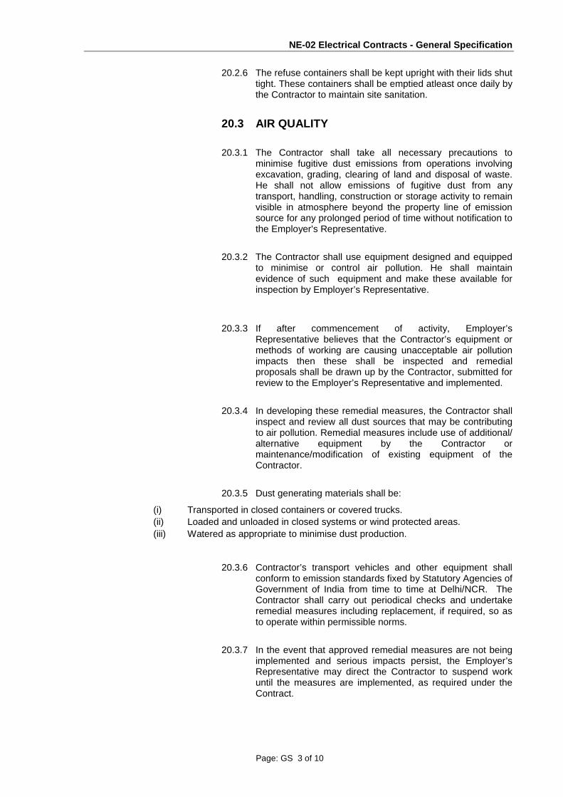
NE-02 Electrical Contracts - General Specification
Page: GS 3 of 10
20.2.6 The refuse containers shall be kept upright with their lids shut tight. These containers shall be emptied atleast once daily by the Contractor to maintain site sanitation.
20.3 AIR QUALITY
20.3.1 The Contractor shall take all necessary precautions to minimise fugitive dust emissions from operations involving excavation, grading, clearing of land and disposal of waste. He shall not allow emissions of fugitive dust from any transport, handling, construction or storage activity to remain visible in atmosphere beyond the property line of emission source for any prolonged period of time without notification to the Employer's Representative.
20.3.2 The Contractor shall use equipment designed and equipped to minimise or control air pollution. He shall maintain evidence of such equipment and make these available for inspection by Employer’s Representative.
20.3.3 If after commencement of activity, Employer’s Representative believes that the Contractor’s equipment or methods of working are causing unacceptable air pollution impacts then these shall be inspected and remedial proposals shall be drawn up by the Contractor, submitted for review to the Employer’s Representative and implemented.
20.3.4 In developing these remedial measures, the Contractor shall inspect and review all dust sources that may be contributing to air pollution. Remedial measures include use of additional/ alternative equipment by the Contractor or maintenance/modification of existing equipment of the Contractor.
20.3.5 Dust generating materials shall be:
(i) Transported in closed containers or covered trucks. (ii) Loaded and unloaded in closed systems or wind protected areas. (iii) Watered as appropriate to minimise dust production.
20.3.6 Contractor’s transport vehicles and other equipment shall conform to emission standards fixed by Statutory Agencies of Government of India from time to time at Delhi/NCR. The Contractor shall carry out periodical checks and undertake remedial measures including replacement, if required, so as to operate within permissible norms.
20.3.7 In the event that approved remedial measures are not being implemented and serious impacts persist, the Employer’s Representative may direct the Contractor to suspend work until the measures are implemented, as required under the Contract.

NE-02 Electrical Contracts - General Specification
Page: GS 4 of 10
20.3.8 The Contractor shall cover loads of materials, debris and soil transported from construction sites. All trucks carrying loose material should be covered and loaded with sufficient free- board to avoid spills through the tail board or side boards.
20.3.9 The Contractor shall be responsible for ensuring that no earth, rock or debris is deposited on public or private right of way as a result of his operations, including any deposits arising from the movement of loaded/unloaded trucks and/or other construction vehicles.
20.3.10 The Contractor shall make his own arrangements for water for purposes stated in above clauses and wherever it may be required to control air pollution, dust and debris.
20.3.11 The Contractor shall establish and maintain records of routine maintenance program for internal combustion engine powered vehicles and equipment used on this project. He shall keep records available for inspection by Employer’s Representative.
20.3.12 The Contractor shall promptly transport all excavation disposal materials of whatever kind so as not to delay work on the project. Stockpiling of materials will only be allowed at sites designated by the Employer’s Representative.
20.3.13 The Contractor shall protect structures, utilities, pavements and other facilities from disfiguration and damage.
20.3.14 The Contractor shall place excavation materials in the dumping/disposal areas designated in the plans as given in the specifications.
20.3.15 The temporary dumping areas shall be maintained by the Contractor at all times until the excavate is re-utilised for backfilling or as directed by Employer’s Representative.
20.3.16 The Contractor shall place material in a manner that will minimise dust production. Material shall be stabilised each day and wetted, to minimise dust production.
20.3.17 During dry weather, dust control methods must be used daily especially on windy, dry days to prevent any dust from blowing across the site perimeter.
20.3.18 The Contractor will make water sprinklers, water supply and water delivering equipment available at any time that it is required for dust control use.
20.3.19 Dust control activities shall continue even during any work stoppage.

NE-02 Electrical Contracts - General Specification
Page: GS 5 of 10
20.3.20 The Contractor shall water down work sites as required to suppress dust, during handling of excavation soil or debris or during demolition.
20.3.21 At each work site, the Contractor shall provide storage facilities for dust generating materials and shall be:
(i) Closed containers/bins or; (ii) Wind protected shelters or; (iii) Mat covering or; (iv) Walled. Or any combination of the above to the satisfaction of the Employer’s Representative.
20.3.22 The Contractor shall implement his blasting techniques so as to minimise dust generation.
20.4 WATER QUALITY
20.4.1 The Contractor shall comply with the Indian Government legislation and other State regulations in existence in Delhi/UP insofar as they relate to water pollution control and monitoring.
20.4.2 The Contractor shall provide adequate precautions to ensure that no spoil or debris of any kind is pushed, washed, falls or deposited on land adjacent to the site perimeter.
20.4.3 In the event of any spoil or debris from construction works being deposited on adjacent land any silt washed down to any area, then all such spoil, debris or material and silt shall be immediately removed and the affected land and areas restored to their natural state by the Contractor to the satisfaction of the Employer’s Representative.
20.4.4 The Contractor is not allowed to discharge water from the site without the approval of the Employer’s Representative. The Contractor must comply with the requirements of the Central Ground Water Board for discharge of water arising from dewatering. Any water obtained from dewatering systems installed in the works must be either re-used for construction purposes and this water may subsequently be discharged to the drainage system or, if not re-used, recharged to the ground water at suitable acquifer levels. The Contractor must submit his proposals for approval of Employer’s Representative, on his proposed locations of dewatering of excavation and collection of water for either construction re-use or recharge directly to acquifers. The Contractor’s recharge proposals must be sufficient for recharging of the quantity of water remaining after deduction of water re-used for construction. The Contractor will not be permitted to directly discharge, to the drainage system, unused ground water obtaining from the excavation without obtaining approval of Employer’s Representative or the Agency controlling the system.

NE-02 Electrical Contracts - General Specification
Page: GS 6 of 10
20.4.5 The Contractor shall prevent soil particles and debris from entering the wells or water discharge points by use of filters and sedimentation basins as required.
20.4.6 The Contractor shall provide treatment facilities as necessary to prevent the discharge of contaminated ground water.
20.4.7 The Contractor shall at all times ensure that all existing stream courses and drains within, and adjacent to the site are kept safe and free from any debris and any excavated materials arising from the Works. The Contractor shall ensure that earth, bentonite, chemicals and concrete agitator washings etc. are not deposited in the watercourses but are suitably treated and effluents and residue disposed off in a manner approved by local authorities.
20.4.8 All water and waste products (surface runoff and wastewater) arising on the site shall be collected and removed from the site via a suitable and properly designed temporary drainage system and disposed off at a location and in a manner that will cause neither pollution nor nuisance.
20.4.9 Any mud slurry from drilling, tunnelling, diaphragm wall construction or grouting etc. shall not be discharged into the drainage system unless treatment is carried out that will remove silt, mud particles, bentonite etc.
20.4.10 The Contractor shall discharge wastewater arising out of site office, canteen or toilet facilities constructed by him into sewers after obtaining prior approval of agency controlling the system. A wastewater drainage system shall be provided to drain wastewater into the sewerage system.
20.4.11 Oil removal / interceptors shall be provided to treat oil waste from workshop areas etc.
20.4.12 The Contractor shall take measures to prevent discharge of oil and grease during spillage from reaching drainage system or any water body through Spill Prevention and Control Plan.
20.5 NOISE
20.5.1 General
(1) The Contractor shall consider noise as an environmental constraint in his planning
and execution of the Works. The Contractor shall, at his own expense, take all appropriate measures to ensure that work carried out by the Contractor and by his sub-Contractors, whether on or off the Site, will not cause any unnecessary or excessive noise which may disturb the occupants of any nearby dwellings, schools, hospitals, or premises with similar sensitivity to noise.
(2) Without prejudice to the generality of the foregoing, noise level reduction measures
shall include the following:

NE-02 Electrical Contracts - General Specification
Page: GS 7 of 10
(a) the Contractor shall ensure that all powered mechanical equipment used in the Works shall be effectively sound reduced using the most modern techniques available including but not limited to silencers and mufflers.
(b) the Contractor shall construct acoustic screens or enclosures around any parts of the Works from which excessive noise may be generated.
(3) The Contractor shall ensure that noise generated by work carried out by the
Contractor and his sub-Contractors during day time and night time shall not exceed the maximum permissible noise limits, as given in the Employer’s Environmental Quality Management Manual. The same may be varied from time to time by and at the sole discretion of the Employer’s Representative, In the event of a breach of this requirement, the Contractor shall immediately re-deploy or adjust the relevant equipment or take other appropriate measures to reduce the noise levels and thereafter maintain them at levels which do not exceed the said limits. Such measures may include without limitation the temporary or permanent cessation of use of certain items of equipment.
(4) The noise monitoring requirements are given in the Employer’s Environment Quality
Management Manual. However, the monitoring locations shall be decided in consultation with the Employer’s Representative.
20.5.2 Construction material should be handled and transported in such a manner as not to create unnecessary noise as outlined below.
20.5.3 Under the Contract, the Contractor shall:
(1) Perform Work within the procedures outlined herein and comply with applicable
codes, regulations, and standards established by the Central and State Government and their agencies.
(2) Keep noise to the lowest reasonably practicable level. Appropriate measures will be
taken to ensure that construction works will not cause any unnecessary or excessive noise, which may disturb the occupants of any nearby dwellings, schools, hospitals, or premises with similar sensitivity to noise. Use equipment with effective noise-suppression devices and employ other noise control measures as to protect the public.
(3) Schedule and conduct operations in a manner that will minimize, to the greatest extent
feasible, the disturbance to the public in areas adjacent to the construction activities and to occupants of buildings in the vicinity of the construction activities.
(4) The Contractor shall submit to the Employer’s Representative a Noise Monitoring and
Control Plan (NMCP) under contract specific Site Environmental Plan. It shall include full and comprehensive details of all powered mechanical equipment, which he proposes to use during daytime and nighttime, and of his proposed working methods and noise level reduction measures. The NMCP shall include detailed noise calculations to demonstrate the anticipated noise generation by the Contractor.
(5) The NMCP prepared by the Contractor shall guide the implementation of construction
activity. The NMCP will be reviewed on a regular basis and updated as necessary to assure that current construction activities are addressed. It shall appear as a regular agenda item in project coordination meetings.
20.5.4 Vibration Level Limits

NE-02 Electrical Contracts - General Specification
Page: GS 8 of 10
The vibration level limits at historical sites adjacent to the alignment shall conform to revised version of the German Standard (DIN 4150). The scheme for monitoring vibration level at these historical sites shall be submitted to Employer’s Representative for his approval. The scheme shall include:
1 monitoring requirements for vibrations at regular intervals throughout the construction period. 2 pre-construction structural integrity inspections of historic and sensitive structures in project activity. 3 Information dissemination about the construction method, probable effects, quality control measures and precautions to be used.
20.6 WASTE
20.6.1 The Contractor shall handle waste in a manner that ensures they are held securely without loss or leakage thus minimising potential for pollution.
20.6.2 The Contractor shall remove waste in a timely manner. Scrap and waste material shall be removed and disposed off at landfill sites after obtaining approval of Conservancy and Sanitation Engineering Department of Municipal Corporation of Delhi/local statutory bodies as applicable for its disposal.
20.6.3 Burning of wastes is prohibited. The Contractor shall not burn debris or vegetation or construction waste on the site but remove it in accordance with (2) above.
20.6.4 The Contractor shall maintain and clean waste storage areas regularly.
20.6.5 If encountered or generated as a result of Contractor’s activity, then waste classified as hazardous under the “Hazardous Wastes (Management & Handling) Rules, 1989” and chemicals classified as hazardous chemicals under “Manufacture, Storage and Import of Hazardous Chemical Rules,1989 of Environment (Protection) Act,1986 `shall be disposed off in a manner in compliance with the procedure given in the rules under the aforesaid act.
20.7 PREVENTION OF MOSQUITO BREEDING
20.7.1 Measures shall be taken to prevent mosquito breeding at site. The measures to be taken shall include:
(a) empty cans, oil drums, packing and other receptacles which may retain water shall be deposited at a central collection point and shall be removed from the Site regularly;
(b) still waters shall be treated at least once every week with oil in
order to prevent mosquito breeding;
(c) Contractor’s Equipment and other items on the Site which may

NE-02 Electrical Contracts - General Specification
Page: GS 9 of 10
retain water shall be stored, covered or treated in such a manner that water could not be retained.
(d) Water storage tanks shall be suitably provided.
20.7.2 Posters in both Hindi and English which draw attention to the dangers of permitting mosquito breeding shall be displayed prominently on the Site.
∗ End of Chapter ∗

NE-02 Electrical Contracts - General Specification
Page: GS 10 of 10
Page Intentionally Blank

NE-02 Electrical Contracts - General Specification
Page: GS21- 1 of 2
CHAPTER 21
21. PHOTOGRAPHS
21.1 Photographs
21.1.1 Colour progress photographs showing the progress of the Works and the quality of the materials and workmanship shall be taken by the Contractor. The photographs shall be taken by a professional photographer, nominated by the Contractor and reviewed without objection by the Employer’s Representative. Processing shall be carried out by a competent processing firm, nominated by the Contractor and reviewed without objection by the Employer’s Representative. The photographs shall be taken under the direction of the Employer or the Employer’s Representative at locations selected by the Employer or the Employer’s Representative. Photographs shall be taken once every month and at other times instructed by the Employer or the Employer’s Representative.
21.1.2 One proof 3R print of each progress photograph shall be provided to the Employer’s Representative not more than 2 days after the photographs are taken. The Employer’s Representative shall select the sets of progress photographs to be provided. The selected sets shall be provided not more than 2 days after the Employer’s Representative has selected the sets. The following shall be provided for the Employer’s Representative:
1. one set of each selected progress photograph comprising the negatives and three 3R prints;
2. albums for the photographs and negatives; and
3. printed labels for each photograph.
21.1.3 The Contractor shall provide to the Employer’s Representative the photographs selected in clause 0 above on Photo Compact Disks with a minimum resolution of 64 Base (4096 x 6144).
21.1.4 The Contractor may propose to the Employer’s Representative the use of a digital photography system to meet the requirements of this Chapter. The Employer’s Representative shall at his discretion, review the proposed system for practical and technical compliance.
21.1.5 Colour progress photographs shall provide a fair representation of the Works. A minimum of 24 photographs per month shall be submitted to the Employer’s Representative.
End of Chapter ∗

NE-02 Electrical Contracts - General Specification
Page: GS21- 2 of 2
Page Intentionally Blank

NE-02 Electrical Contracts - General Specification
Page: GS22- 1 of 6
CHAPTER 22
22 TEMPORARY ELECTRICITY SUPPLY
22.1 Electricity Supply for the Contractor by the Project Civil Contractors Please Refer Clause 56 of SCC
22.2 Applicability
22.2.1 Where the Contractor is required to provide temporary electrical supplies, or to use, extend or expand on temporary supplies installed by others, all such activity shall be executed in accordance with clauses 22.3 to 22.19 inclusive.
22.2.2 When the Contractor makes use of temporary electrical supplies provided by other, viz. Project (Civil) Contractors, he will observe and comply with the requirements of this Chapter.
22.3 Work on Site
22.3.1 The Contractor shall nominate a representative whose name and qualifications shall be submitted in writing to the Employer’s Representative for review not later than 4 weeks before the appointment and who shall be solely responsible for ensuring the safety of all temporary electrical equipment on Site. The Contractor shall not install or operate any temporary Site electrical systems until this representative is appointed and has commenced duties.
22.3.2 The name and contact telephone number of the representative having been reviewed without objection by the Employer’s Representative shall be displayed at the main distribution board for the temporary electrical supply so that he can be contacted in case of an emergency.
22.3.3 The Contractor shall submit schematic diagrams and the details of the equipment for all temporary electrical installations, and these diagrams together with the temporary electrical equipment shall be submitted to the Employer’s Representative for review.
22.3.4 All electrical installation work on Site shall be carried out in accordance with the requirements laid down in BS 7375 and the Specification. All work shall be supervised or executed by qualified and suitably categorised electricians, who are registered as such under the Electricity Ordinance 1990/Electricity (Registration) Regulations 1990.

NE-02 Electrical Contracts - General Specification
Page: GS22- 2 of 6
22.4 Electrical General
Temporary electrical Site installations and distribution systems shall be in accordance with:-
1. Indian Electrical Regulations;
2. The Power Companies’ Supply Rules;
3. Electricity and its subsidiary Regulations;
4. IEE Wiring Regulations (16th Edition);
5. BS 7375 Distribution of Electricity on Construction and Building Sites;
6. BS 4363 Distribution Assemblies for Electricity Supplies for Construction and Building Sites; and
7. Any other applicable national standards
22.5 Materials, Appliances and Components
All materials, appliances and components used within the distribution system shall comply with BS 4363 and BS 7375 Appendix A.
22.6 Mains Voltage
22.6.1 The Site mains voltage shall be as the Electricity Companies’ Utility supplies, 415V 3-phase 4 wire system.
22.6.2 Single-phase voltage shall be as the Electricity Companies' Utility supplies, 240V supply.
22.6.3 Reduced voltages shall conform to BS 7375.
22.7 Types of Distribution Supply
22.7.1 The following voltages shall be adhered to for typical applications throughout the distribution systems:
1) fixed plant - 415V 3 phase;
2) movable plant fed by trailing cable - 415V 3 phase;
3) installations in Site buildings - 240V 1 phase;
4) fixed flood lighting – 240V 1 phase;
5) portable and hand held tools - 115V 1 phase;

NE-02 Electrical Contracts - General Specification
Page: GS22- 3 of 6
6) Site lighting (other than flood lighting) - 115V 1 phase; and
7) portable hand-lamps (general use) - 115V 1 phase.
22.7.2 When the low voltage supply is energised via the Employer's transformer, any power utilised from that source shall be either 415V 3 phase or / 240V single phase as appropriate. The Contractor shall carry out any conversion that may be necessary to enable him to use power from that source.
22.8 Protection of Circuits
22.8.1 Protection shall be provided for all main and sub-circuits against excess current, residual current and earth faults. The protective devices shall be capable of interrupting (without damage to any equipment or the mains or sub-circuits) any short circuit current that may occur.
22.8.2 Discrimination between circuit breakers, circuit breakers and fuses shall be in accordance with:-
1) BS 88;
2) BS EN 60898; and
3) BS 7375;
4) Any other appropriate Indian Standards.
22.9 Earthing
22.9.1 Earthing and bonding shall be provided for all electrical installations and equipment to prevent the possibility of dangerous voltage rises and to ensure that faults are rapidly cleared by installed circuit protection.
22.9.2 Earthing systems shall conform to the following standards:-
1) IEE Wiring Regulations (16th Edition);
2) BS 7430;
3) BS 7375; and
4) IEEE Standard 80 Guide for Safety in AC Substation Grounding.
22.10 Plugs, Socket Outlets and Couplers
Low voltage plugs, sockets and couplers shall be colour coded in accordance with BS 7375, and constructed to conform to BS EN 60309. High voltage couplers and 'T' connections shall be in accordance with BS 3905.

NE-02 Electrical Contracts - General Specification
Page: GS22- 4 of 6
22.11 Cables 22.11.1 Cables shall be selected after full consideration of
the conditions to which they will be exposed and the duties for which they are required. Supply cables up to 3.3KV shall be in accordance with BS 6346. The cable armouring shall be used as the earth return in conditions where the cable is continuously extended and not subject to continuous movement after installation.
22.11.2 For supplies to mobile or transportable equipment where operation of the equipment
subjects the cable to flexing, the cable shall conform to one of the following standards appropriate to the duties imposed on it:
1) BS 6708 flexible cables for use at mines and quarries;
2) BS 6007 rubber insulated cables for electric power and lighting; and
3) BS 6500 insulated flexible cords and cables.
22.11.3 Where low voltage cables are to be used, reference shall be made to BS 7375. The
following standards shall also be referred to particularly for underground cables:-
1) BS 6346 for armoured PVC insulated cables; and
2) BS 6708 Flexible cables for use at mines and quarries.
22.11.4 All cables which have a voltage to earth exceeding 65 V (except for supplies from
welding transformers to welding electrodes) shall be of a type having a metal sheath and/or armour which shall be continuous and effectively earthed. In the case of flexible or trailing cables, such earthed metal sheath and/or armour shall be in addition to the earth core in the cable and shall not be used as the sole earth conductor.
22.11.5 Armoured cables having an over-sheath of polyvinyl chloride (PVC) or an oil resisting
and flame retardant compound shall be used whenever there is a risk of mechanical damage occurring.
22.11.6 For resistance to the effects of sunlight, overall non-metallic covering of cables shall
be black in colour.
22.11.7 Cables which have applied to them a voltage to earth exceeding 12 V but not normally exceeding 65 V shall be either one of the type as described in clause 22.11.5 above or alternatively of a type insulated and sheathed with a general purpose or heat resisting elastomer.
22.11.8 All cables that are likely to be frequently moved in normal use shall be flexible cables.

NE-02 Electrical Contracts - General Specification
Page: GS22- 5 of 6
22.11.9 Flexible cables shall be in accordance with BS 6500 and BS 7375.
22.12 Lighting Installation
22.12.1 Lighting circuits shall be run separate from other sub-circuits and shall be in accordance with BS 7375 and BS 4363.
22.12.2 Voltage shall not exceed 55 V to earth except when the supply is to a fixed point and where the lighting fixture is fixed in position.
22.12.3 Luminaries shall have a degree of protection not less than IP 54. In particularly bad environments where the luminaries are exposed to excesses of dust and water, a degree of protection to IP 65 shall be employed.
22.12.4 Where the Employer’s Representative requires Site inspection of the Works, the Contractor shall upgrade the lighting level to a minimum of 200 lux by localised lighting in all areas.
22.12.5 Use of wire guards or other such devices shall provide mechanical protection of luminaries against damage by impact whenever risk of damage occurs.
22.13 Electrical Motors
22.13.1 Totally enclosed fan cooled motors to BS 4999:Part 105 shall be used.
22.13.2 Motor control and protection circuits shall be as stipulated in BS 6164. Emergency stops for machinery shall be provided.
22.14 Inspection and Testing Electrical installations on Site shall be inspected and tested in accordance with the requirements of the IEE Wiring Regulations (16th Edition).
22.15 Identification Identification labels of a type reviewed without objection by the Employer’s Representative shall be affixed to all electrical switches, circuit breakers and motors to specify their purpose.
22.16 Maintenance Strict maintenance and regular checks of control apparatus and wiring distribution systems shall be carried out by an electrician (duly qualified to carry out the said checks) to ensure safe and efficient operation of the systems. The Contractor shall submit for review by the Employer’s Representative details of his maintenance schedule and maintenance works record.

NE-02 Electrical Contracts - General Specification
Page: GS22- 6 of 6
22.17 Maintenance Record All portable electrical appliances shall be permanently numbered (scarf tag labels or similar) and a record kept of the date of issue, date of the last inspection carried out and the recommended inspection period.
22.18 Metering
22.18.1 For the purposes of the clause 22.18 above, “construction works” shall mean the Works excluding both the Contractor's on and off Site, fabrication facilities, workshops, work-yards, offices and stores.
22.18.2 The Contractor shall install a separately metered and invoiced supply or supplies of electricity for:-
1) Site fabrication facilities;
2) Site workshops and work-yards; and
3) Site offices and stores.
22.19 Inability to Supply
Wherever, the Project Contractor is not in a position to supply construction power and water supply to the System wide Contractor, he ( the System wide Contractor) shall arrange for his own separate construction power and water supply.
End of Chapter ∗

NE-02 Electrical Contracts - General Specification
Page: GS 23-1 of 1
CHAPTER 23
23 NOT USED

NE-02 Electrical Contracts - General Specification
Page: Appx: 1-1 of 4
APPENDIX 1
MONTHLY PROGRESS REPORT
1.Topics
1.1 The Monthly Progress Report required under clause 2.17 of the GS shall include as a minimum the following sections and topics:
1 Executive Summary, highlighting any matters of concern and explaining corrective action to be taken
2 Programme and overall progress
3 Physical progress report (see Paragraph 2.19 of the General Specification)
4 Achievement of Key Dates and Milestone Dates planned vs actual dates
5 Interface;and Interface co-ordination progress
6 Approval of design and drawings, vendor finalisation
7 Issue of purchase orders for equipments, expected date of inspection, expected date of arrival at site.
8 Installation / erection on Site
9 Commissioning activity
10 System integration tests
11 Training
12 Maintenance issues
13 Payments / invoices
14 Employer’s Representative’s instructions and variation orders
15 Claims / potential claims
16 Contractor’s resources (details of all staff and sub-contractors engaged on the Works)
2. PROGRESS REPORTS The Monthly Progress Reports shall be accompanied by:
a) the Works Programme, marked to show the status of
progress to date;
b) control schedules for document submissions and
issues of a repetitive or multiple nature;
c) where appropriate, exception reports to highlight any
problem areas including any submissions and
information which are overdue;

NE-02 Electrical Contracts - General Specification
Page: Appx: 1-2 of 4
d) the programme analysis report, in accordance with
Paragraph 2.18 of the General Specification;
e) the physical progress (earned value) report, in
accordance with Paragraph 2.20 of the General
Specification;
f) “S” curve showing current status of the Contract;
g) a full list of all submissions and their current status in
comparison to the Submissions Programme. Special
commentary shall be provided for each item that is late
to this programme giving the reasons for the delay and
the proposed corrective action that will ensure that the
delay does not affect any overall or stage completion
dates, particularly those that interface with other
parties;
h) identification and discussion of significant
accomplishments, problem areas encountered, actions
taken or planned to resolve actual or potential
problems and conflicts, and other comments or
proposals on matters (including the interfacing works)
affecting or likely to affect the Works; and
i) a critical items action list which identifies outstanding
problems associated with the timely completion of the
Works including anticipated actions for their resolution.
2.1 The programmes shall show current status to provide a comparison between the
Works Programme and reported progress.
2.2 Actual progress shall be reported for each activity in the Works Programme in the following terms:
1 the percentage of the work which is complete; 2 the remaining duration of the work; 3 the actual start date; and 4 the actual completion date.
2.3 Actual progress shall reflect the physical scope of the work that has been completed
and shall not be calculated based on elapsed time or hours worked. Any automatic statistical indications in the Contractor’s software that is based on this principle shall be disabled.
2.4 Each Monthly Progress Report shall include a programme activity listing and an
analysis report. All activities that have negative float shall be analysed by the Contractor to identify the impact on the achievement of target dates.

NE-02 Electrical Contracts - General Specification
Page: Appx: 1-3 of 4
3.0 Copies
3.1 The Contractor shall submit 1 unbound original and 4 bound hard copies of all Monthly
Progress Reports and of the accompanying documents plus one copy in electronic format on PC compatible 3-1/2” diskettes compatible with Microsoft Office and Primavera P3 applications.
5 End of Appendix 1 ∗

NE-02 Electrical Contracts - General Specification
Page: Appx: 1-4 of 4
Page Intentionally Blank

NE-02 Electrical Contracts - General Specification
Page: Appx: 2-1 of 2
APPENDIX 2
NOT USED

NE-02 Electrical Contracts - General Specification
Page: Appx: 2-2 of 2
Page Intentionally Blank

NE-02 Electrical Contracts - General Specification
Page: Appx: 3-1 of 2
APPENDIX 3
4 SUBMISSION FOR REVIEW REQUEST FORM
SUBMISSION FOR REVIEW REQUEST
Reference No. (see Paragraph 4.3.2) Date
Programme reference and scheduled date:
Submission Stage (see Paragraph 3.5.1.1)
Title
We hereby submit for review by the Employer’s Representative the documents or articles listed below:
(Introduction and list of items submitted – see Paragraph 4.3.5.2 – continue on separate sheet if necessary)
I confirm that the material submitted is in full compliance with the Contract.
Signed (Contractor’s responsible engineer)
Employer’s Representative’s Response Dated
The material submitted has been reviewed and the following decision is given:
“No Objection” / “No Objection Subject To” (see below) / “Rejected” (see below)
The following comments are made and a re-submission is to be made by the Contractor within 10 working days demonstrating fully how all of these are taken into account:
(Employer’s Representative’s comments)
Signed (Employer’s Representative)
5 End of Appendix 3 ∗

NE-02 Electrical Contracts - General Specification
Page: Appx: 3-2 of 2
Page Intentionally Blank

NE-02 Electrical Contracts - General Specification
Page: Appx: 4-1 of 3
APPENDIX 4
SCHEDULE OF ITEMS TO BE SUBMITTED BY CONTRACTOR
This Appendix lists the principal items to be submitted by the Contractor for review by the Employer’s Representative. This list is not exhaustive and the Contractor is reminded to satisfy itself of the requirements for all submissions whether or not they are included within this Appendix. Engineer at his sole discretion may accept any genuine delay in submission of the items mentioned in the list below
Article Reference
Paragraph(s) To be submitted
Works Programme 2.4.1.2 Within 60 days of the Commencement Date of the Works
Submissions Programme 2.5.1 Within 30 days of the Commencement Date of the Works
Procurement and Manufacturing Programme
2.6.1 Within 60 days of the Commencement Date of the Works
Material Control Schedule 2.6.5 As stated in the PS, or if none is given, within 60 days of the Commencement Date of the Works
Factory Testing Programme 2.6.8 Within 60 days of the Commencement Date of the Works
Installation Programme 2.7.1 Preliminary version within 60 days of the Commencement Date of the Works. Full version as stated in the PS or as directed by the Employer’s Representative
Testing & Commissioning Programme
2.8.1 Preliminary version within 60 days of the Commencement Date of the Works. Full version as stated in the PS or as directed by the Employer’s Representative
Monthly Progress Report and supporting documentation
2.17.1 The 5th day of each month.
Contractor’s Project Plan 3.1.2 As stated in the PS, or if none is given, within 60 days of the Commencement Date of the Works
Particulars of agent 3.3.1.6 (6) 30 days before the Commencement Date of the Works
Interface Management Plan 3.3.2 b) Within 60 days of notification from the Employer’s Representative of the identity of each Project Contractor
Detailed Interface Document
3.3.2 d) Within 90 days of notification from the Employer’s Representative of the identity of each Project Contractor
Contractor’s Factory Testing Plan
3.5.1 As stated in the PS, or if none is given, within 60 days of the Commencement Date of the Works
Test Reports 3.5.1.7 Immediately after the completion of Factory Testing Procurement, Manufacturing and Delivery Plan
3.5.2 As stated in the PS, or if none is given, within 60 days of the Commencement Date of the Works

NE-02 Electrical Contracts - General Specification
Page: Appx: 4-2 of 3
Article Reference Paragraph(s)
To be submitted
Contractor’s Health and Safety Documentation
3.6.2.2 Within 30 days of the Commencement Date of the Works
Commissioning Plan 3.7.2.1 First draft within 180 days of the Commencement Date of the Works
Installation Test Schedule 3.7.2.2 b. (i) As stated in the PS or if not given, not later than two months in advance of the Date scheduled for commencement of respective tests
Partial Acceptance Tests Plan
3.7.2.2 b. (ii) As stated in the PS or if not given, not later than four months in advance of the Date scheduled for commencement of Partial Acceptance Tests
System Acceptance Tests Plan
3.7.2.2 b. (iii) As stated in the PS or if not given, not later than four months in advance of the Date scheduled for commencement of System Acceptance Tests
Integration Tests & Commissioning Plan
3.7.2.2 b. (iv) As stated in the PS or if not given, not later than four months in advance of the Date scheduled for commencement of Tests on Completion
Operation & Maintenance Manuals Plan
3.7.3.2 As stated in the PS or if not given, not later than nine months prior to the issue of the Taking Over Certificate for the Works
Training Plan 3.7.4.2 As stated in the PS or if not given, not later than six months prior to the issue of the Taking Over Certificate for the Works
Defects Liability Management Plans
3.7.6 Upon issuance of the Taking Over Certificate
Project Document Control Procedure
4.3.2 Within 28 days of the Commencement Date of the Works
Quality Manual 5.2.3 Within 30 days of the Commencement Date of the Works
Quality System Procedures 5.2.3 Within 30 days of the Commencement Date of the Works
Details of Quality Manager 5.2.6 Within 30 days of the Commencement Date of the Works
Proposed Corrective & Preventive Action Plan
5.2.7 Within 14 days of issue of CAR
Management Quality Plan 5.3 Within 30 days of the Commencement Date of the Works
Site Quality Plan 5.5 60 days prior to the commencement of the construction works
Reports of Quarterly Quality Audits
5.7.2 Every Three months
Quality Control Register 5.8 7th working day of every month Packaging Materials & Procedures
8.4.1 As stated in the PS, or if none is given, within 60 days of the Commencement Date of the Works
Latest drawings, test procedures, specifications and quality documentation for inspection of equipment
9.2.7.4 At least 15 days prior to each First Article Inspections ( FAI )
Installation Tests Reports 9.4.3.3 Immediately after the completion of each test Proposed Partial Acceptance Tests Records
9.4.4.7 As stated in the PS or if not given, not later than two months in advance of the Date scheduled for commencement of tests

NE-02 Electrical Contracts - General Specification
Page: Appx: 4-3 of 3
Article Reference Paragraph(s)
To be submitted
Partial Acceptance Tests Records
9.4.4.9 Immediately following the successful Partial Acceptance Tests
System Acceptance Tests Records
9.4.5.8 Immediately following the successful System Acceptance Tests
Integration Tests & Commissioning Records
9.4.6.8 Immediately following the successful Tests on Completion of the system
Service Trial Records 9.4.7.8 Immediately following the successful Service Trial of the system
Summaries of Inspection and/or Test
9.6.11 7th day of the following month
Operation & Maintenance documentation (Draft Version)
11.4.1 As stated in the PS or if not given, not later than 6 months prior to the issue of the Taking Over Certificate for the Works
Operation & Maintenance documentation (Final Version)
11.4.3 As stated in the PS or if not given, not later than 1 month prior to the issue of the Taking Over Certificate for the Works
Operating & Maintenance instructions and illustrated parts list (Final Submission)
11.4.3 At a date set by the Employer’s Representative
Spare Parts List 13.1.3 As stated in the PS Construction & Installation Plan
14.1.1 As stated in the PS, or if none is given, within 60 days of the Commencement Date of the Works, and in any case not less than 12 weeks before starting the construction of the Works on Site
Proposals for the construction of the Employer’s Representative’s Site Offices
0 Within 14 days of the Commencement Date of the Works
Particular Uses of Site 17.2.1 Within 14 days of the Commencement Date of the Works
Detailed written report of accidents, incidents and dangerous occurrence
18.6.4.1 Within 7 days of occurrence/accident
Name and qualification of safety representative for temporary site electricity
22.3.1 Not later than 4 weeks before appointment
6 End of Appendix 4 ∗


NE-02 Electrical Contracts - General Specification
Page: Appx: 5-1 of 11
APPENDIX 5
TYPICAL TYPE TEST REQUIREMENTS
1 Electronic and Electrical Equipment The initial visual inspection shall be carried out to ensure that the equipment is of sound construction and, so far as can be ascertained, meets the requirements of the Specification.
1.1 Initial Performance Test (i) The initial performance tests shall consist of a comprehensive series of
measurements of the characteristics of the equipment to demonstrate that
its performance is in accordance with its functional requirements,
including detailed requirements of the Specification.
(ii) This test shall normally be performed at an ambient temperature of 40°C
+5°C while supplied at its normal voltage and frequency, if relevant.
(iii) This test shall extend to demonstrating compliance with any limitation on
self-generated vibration or interference as stated in the Specification.
1.2 Modes of Testing
(i) Electrical tests will generally be applied to the 'external terminals' of the
item of equipment to be tested which are normally used to interface the
subject equipment to other equipment or external circuits, e.g. power
supply terminals, signal input/output terminals, frame (safety) earth
terminals, etc. Tests may be applied in Common Mode and/or Series
Mode, as described below.
(ii) Common mode tests generally involve testing circuits with respect to the
equipment's frame earth. All accessible metal parts (intended to be
connected to earth) are to be connected to the frame earth.
(iii) All the terminals of the circuit to be tested shall be connected together,
where practicable. All terminals of circuits not involved in the test shall
preferably be connected to earth.
For example, a common mode test on the AC power supply circuit of an item of
equipment would involve connecting all the supply circuit terminals together (e.g.
phase (s) and neutral) and applying the test between those connected terminals
and the equipment's frame earth terminal. The terminals of all other circuits, e.g.
signal input/output terminals, shall preferably be connected to earth.
(iv) Series mode tests generally involve testing circuit connections with
respect to each other.
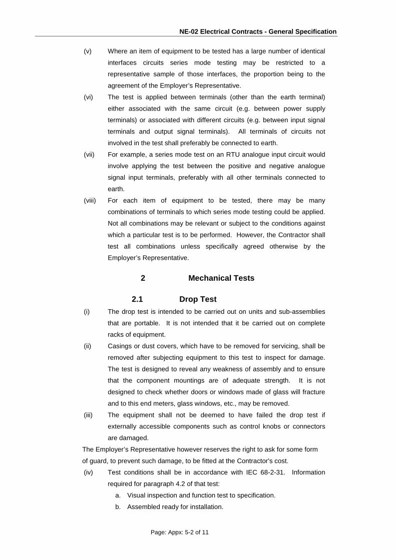
NE-02 Electrical Contracts - General Specification
Page: Appx: 5-2 of 11
(v) Where an item of equipment to be tested has a large number of identical
interfaces circuits series mode testing may be restricted to a
representative sample of those interfaces, the proportion being to the
agreement of the Employer’s Representative.
(vi) The test is applied between terminals (other than the earth terminal)
either associated with the same circuit (e.g. between power supply
terminals) or associated with different circuits (e.g. between input signal
terminals and output signal terminals). All terminals of circuits not
involved in the test shall preferably be connected to earth.
(vii) For example, a series mode test on an RTU analogue input circuit would
involve applying the test between the positive and negative analogue
signal input terminals, preferably with all other terminals connected to
earth.
(viii) For each item of equipment to be tested, there may be many
combinations of terminals to which series mode testing could be applied.
Not all combinations may be relevant or subject to the conditions against
which a particular test is to be performed. However, the Contractor shall
test all combinations unless specifically agreed otherwise by the
Employer’s Representative.
2 Mechanical Tests
2.1 Drop Test (i) The drop test is intended to be carried out on units and sub-assemblies
that are portable. It is not intended that it be carried out on complete
racks of equipment.
(ii) Casings or dust covers, which have to be removed for servicing, shall be
removed after subjecting equipment to this test to inspect for damage.
The test is designed to reveal any weakness of assembly and to ensure
that the component mountings are of adequate strength. It is not
designed to check whether doors or windows made of glass will fracture
and to this end meters, glass windows, etc., may be removed.
(iii) The equipment shall not be deemed to have failed the drop test if
externally accessible components such as control knobs or connectors
are damaged.
The Employer’s Representative however reserves the right to ask for some form
of guard, to prevent such damage, to be fitted at the Contractor's cost.
(iv) Test conditions shall be in accordance with IEC 68-2-31. Information
required for paragraph 4.2 of that test:
a. Visual inspection and function test to specification.
b. Assembled ready for installation.

NE-02 Electrical Contracts - General Specification
Page: Appx: 5-3 of 11
c. Connectorised cables removed, casings or covers in place.
d. Not applicable.
e. All.
f. 25mm, 6 times.
g. 25mm, 6 times.
(v) Visual inspection and function test to specification.
(vi) Topple (or push over) test is not required.
2.2 Vibration Test
(i) The vibration test is designed to reveal any parts or components of the
equipment that may be prone to any resonance severe enough to cause
possible damage or malfunctioning.
(ii) The test shall be in accordance with IEC 68-2-6 1982. Information
required for Chapter 12 of that standard:
a. Measuring Points: If four or less fixing points are used for the specimen,
these shall also be used as checkpoints. If more than four fixing points
are used then those nearest the corners shall be used as checkpoints.
The checkpoints shall be located as close as possible to the fixing
points.
b. Transverse Motion: Any transverse motion in excess of that specified in
the above standard clause 4.1.2 shall be noted and recorded in the test
results.
c. Distortion: As defined in clause 3 in
excess of the limits in clause 4.1.3 of the
above standard shall be noted as
defined in clause 4.1.3 paragraph 4 of
the same standard.
d. Derivation of Control Signal Single point.
e. Tolerances at check points shall be as
clause 4.1.4.2 of the above standard.
Where these cannot be achieved, the
actual values shall be recorded.
f. Monitoring of Specimen(s): The
equipment shall be rigidly mounted in a
jig so designed as to transmit the input
vibration with minimum modification.
2.3 Vibration Test 1
(i) Equipment intended for use with vibration isolators shall normally be
tested with its isolator. When this is not possible, the equipment shall be

NE-02 Electrical Contracts - General Specification
Page: Appx: 5-4 of 11
rigidly secured to the vibrator and the input vibration levels modified to
include transmissibility of the isolators.
(ii) Equipment under test is to be mounted in its normal operational attitude.
(iii) Frequency Range: See Chapter 6, Paragraph 5.5 (Equipment
Requirements).
(iv) Vibration Amplitude: See Chapter 6, Paragraph 5.5 (Equipment
Requirements).
(v) Special crossover frequency: See Chapter 6, Paragraph 5.5 (Equipment
Requirements).
(vi) Type and duration of endurance:
a. Endurance by sweeping 6 hours, i.e. 2 hours per axis
b. Endurance at critical frequencies (as defined in the above standard
clause 8.1): 1 minute at each frequency providing not more than four
such frequencies exist per axis.
(vii) Pre-conditioning: None.
(viii) Initial measurements Functional test to the appropriate test procedure.
(ix) Axes of vibration: Three mutually perpendicular axes in turn.
(x) Force Limitation: Not required.
(xi) Test stages to be performed in the sequence below:
a. Vibration response investigation.
b. Endurance at fixed frequencies derived from vibration response investigation.
c. Endurance by sweeping.
(xii) The equipment functionality shall be verified throughout the sweep test to
the appropriate test procedure.
(xiii) Action to be taken after vibration response investigation. If less than four
critical frequencies are found in each axis, then endurance testing for the
prescribed duration shall be performed at each frequency.
(xiv) Final response test not required.
(xv) Predetermined frequencies shall be derived from the vibration response
investigation.
(xvi) Conditioning at the resonance frequencies of the specimen on its isolators
(where fitted) shall be included.
(xvii)Final measurements Functional test to the appropriate test
procedure.
(xviii) Any resonance liable to affect the performance or reliability of the
equipment shall be reduced to an acceptable level by suitable modifications and
the complete test repeated.

NE-02 Electrical Contracts - General Specification
Page: Appx: 5-5 of 11
3 ENVIRONMENTAL TESTS
3.1 Dry Heat Test (i) The dry heat test shall be carried out on each complete piece of
equipment or assembly, with all doors and covers being in place and
closed as in normal operation.
(ii) Test conditions shall be in accordance with IEC 68-2-2. Information
required for paragraph 44 of that test:
a. Laboratory ambient.
b. Visual inspection.
c. Assembled and mounted in rack, enclosure or cabinet ready for
operation or installation.
d. On.
e. Maximum class temperature (see Chapter 6, Chapter 5.2, Equipment
Requirements) for 16 hours.
f. At maximum class temperature after 16 hours, switch on and function
test to specification.
g. Recovery at laboratory ambient.
h. Visual inspection and function test to specification.
i. None.
3.2 Low Temperature Test (in case applicable for Delhi/UP ambient temperature range)
(i) The low temperature test shall be carried out on each complete piece of
equipment or assembly, with all doors and covers being in place and
closed as in normal operation.
(ii) Test conditions shall be in accordance with IEC 68-2-1. Information
required for paragraph 33 of that test:
a. Laboratory ambient.
b. Visual inspection and function test to specification.
c. Assembled and mounted in rack, enclosure or cabinet
ready for operation or installation.
d. Off.
e. Minimum class temperature (see Chapter 6, Paragraph
5.2, Equipment Requirements) for 16 hours.
f. At minimum class temperature after 16 hours, switch on
and function test to specification.
g. Recovery at laboratory ambient.
h. Visual inspection and function test to specification.
i. None.

NE-02 Electrical Contracts - General Specification
Page: Appx: 5-6 of 11
3.3 Change of Temperature Test (i) If both Dry Heat and Low Temperature Tests are required (as decided by
the Employer’s Representative) they may be replaced by a single test in
accordance with IEC 68-2-14.
(ii) Information required for paragraph 2.9 of that test:
(i) Assembled and mounted in rack, enclosure or cabinet ready for
operation or installation.
(ii)Minimum class temperature.
(iii) Maximum class temperature.
(iv) Per Minute.
(v) One.
(vi) Visual inspection.
(vii) On.
(viii) Hours.
(ix) None.
(x) Recovery at laboratory ambient.
(xi) Visual inspection and function test to specification.
3.4 Damp Heat Test 1 The damp heat test shall be carried out on each complete
piece of equipment or assembly, with all doors and covers being in place and closed
as in normal operation.
2 Test conditions shall be in accordance with IEC 68-2-30. Information required for
paragraph 10 of that test:
1 Maximum class temperature, two cycles.
2 Visual inspection and function test to specification.
3 Switched on, ready to use.
4 None.
5 Variant 2.
6 At maximum class temperature after 12 hours, function test to Specification. At 6
hours after the temperature starts to fall a further function test to specification. Tests
to be repeated during second cycle.
7 Laboratory ambient conditions.
8 None.
9 Visual inspection and function test to specification within 4 hours.
3.5 Driving Rain Test 1 The test conditions shall be in accordance with IEC 68-2-
18 Method Rb 2.2.
2 Information required for paragraph 5.3.8 of that document:
1 Minutes/m2 for a minimum of 15 minutes.

NE-02 Electrical Contracts - General Specification
Page: Appx: 5-7 of 11
2 No preconditioning of seals.
3 Visual inspection and function test to specification.
4 Table V1: a = 60°. B = 60°C. duration = 10 minutes.
5 Table V2: diameter = 0.40mm. water flow = 0.10 + 0.005
dm3/min. supply pressure = 80 kpa.
3 Equipment functioning throughout the test to be verified by
testing.
4 Any ingress of water shall be reported to the Employer’s
Representative, the equipment shall be visually inspected
and function tested to Specification.
04 Electrical Tests
4.1 Supply Variations
Measurements of equipment performance and maximum VA consumption shall be made, for supply voltage and frequency variations in all possible combinations of upper limit, normal and lower limit as detailed in the Specification. Throughout these tests, the equipment shall function in accordance with the Specification.
4.2 Supply Interruptions I. The supply input to the equipment under test shall be
interrupted for periods of 10 ms.
II. The tests shall be performed ten times at random for ac
supplies and three times at random for dc supplies.
III.The equipment shall be capable of withstanding these
interruptions of supply input without damage, interruption or
resetting by the operator and shall continue to function and
operate correctly in accordance with the Specification.
4.3 High Frequency Disturbance Test
I. The High Frequency Disturbance test is required to determine whether an item of
equipment will continue to operate correctly when specified high frequency
transients, representative of practical system conditions, are applied to
the fully operating equipment.
II. The test to be applied is based on IEC 255-4, Appendix E.
III. This test shall be performed for all equipment required to operate in environments
subject to Electrical Interference Class 2 or 3 (refer to Table 8-3) and shall be
applied to the AC power supply terminals of that equipment.
IV. Waveform: a damped oscillatory wave with the envelope decaying to 50% of peak
value at the end of three to six cycles.
a. Frequency: 1 MHz tolerance + 10%.
b. Source impedance: 200 ohm tolerance + 10%.

NE-02 Electrical Contracts - General Specification
Page: Appx: 5-8 of 11
c. Repetition rate: the test wave is applied to the equipment
under test at a repetition rate of 400 per second.
d. Duration of test: 2 s tolerance + 10% 0% (see Sub-clause
E5.2.7 of IEC 255-4, Appendix E).
e. Standard value of test voltage: Refer to Table 8-3.
f. Test voltage tolerance: +0 -10%.
V. .The test voltage levels are the voltages at the output of the test circuit before the
equipment to be tested is connected to the test circuit terminals.
VI. The test leads shall not be longer than 2 m.
VII. The disturbance test shall be applied to the AC supply terminals of the
equipment under test in series mode (refer to Sub clause 2.1.3).
VIII. The tests shall be carried out with the equipment operating under nominal supply
conditions.
IX. The equipment shall function in accordance with the Specification throughout the
test.
4.4 Radio Frequency Interference
I. Portable radio communication transmitters are a common source of radio
frequency interference when they are operated in close proximity to equipment.
A field strength of 10 V/m shall be assumed to be present in the VHF and UHF
bands.
II. These field strengths are approximately those expected at a distance of 35 cm
from a 5 watt hand portable radiotelephone. These fields can induce currents of
the order of 100 mA into cables, screens and metalwork.
III. Other possible sources are low level radiation from adjacent equipment including
fluorescent lamps and signals from powerful but more distant radio, television and
radar transmitters.
IV. The test to be applied is based on IEC 801-3 over a frequency range of 27 MHz
to 500 MHz. The Severity Level (Chapter 5) to be applied shall be as follows:
V. The Contractor shall state to what field strength the equipment is immune, and
include as an option the cost of testing to 10 V/m. The equipment functionality
and performance shall not be degraded during or after the RFI test.
VI. With regard to RTUs and tele-protection equipment, the command outputs shall
be immune to mal-operation with the cubicle doors open when the equipment is
subjected to the radiated field strengths mentioned above.
4.5 Electrical Stress Impulse Voltage Withstand
i. The Impulse Voltage Withstand test is designed to
demonstrate that the equipment has been correctly designed
to withstand, without damage, the electrical stresses to which
it might be subjected in practice.

NE-02 Electrical Contracts - General Specification
Page: Appx: 5-9 of 11
ii.The test to be applied is based upon IEC 255-4, Appendix E.
iii. This test shall be performed for all equipment required to operate in
environments subject to Electrical Interference Class 2 or 3 (refer to Table 8-3)
and shall be applied as follows:
a. To all AC power supply input and output terminals of all equipment.
b. To all signal input/output, communication interface and DC power supply
terminals of RTU and tele-protection equipment.
c. For the withstand test, the impulse voltage is a periodic transient voltage
without appreciabe oscillations (see IEC Publication 60, High-voltage Test
Techniques).
iv. Impulse waveform: This shall be the standard 1.2/50 impulse specified in IEC
Publication 60 and having the following tolerances:
a. Voltage rise time: + 30%.
b. Voltage falls time: + 20%.
c. Source impedance: 500 ohm tolerance + 10%.
d. Source energy: 0.5 J tolerance + 10%.
e. Standard value of test voltage: Refer to Table 3.
f. Test voltage tolerance: +0 -10%.
v. The test voltage levels are the voltages at the output of the test circuit before the equipment
to be tested is connected to the test circuit terminals.
vi. The test leads shall not be longer than 2m.
vii. Three positive and three negative impulses shall be applied at intervals of not less
than 5s. Both common mode and series mode tests shall be performed (refer to
Sub-clause 2.1.3).
viii. After the above tests, the equipment shall be visually inspected and function
tested to check compliance with the Specification.
4.6 Insulation Resistance (Across Isolating Barrier) Test
I Where a barrier is used to provide isolation from external circuits, its insulation
resistance shall be measured.
II. If the barrier is required to withstand high voltage stresses, then it shall be
stressed at the specified voltage to demonstrate its withstand capability and a
further insulation resistance test shall be made to ascertain that it has not been
significantly degraded as a result of the stress being applied.
III. The insulation of all circuits that include contacts of switches, relays or
contractors for isolation functions shall be tested for insulation resistance, R1.
R1 shall not be less than 20 mega ohm when measured at 500 V dc.
IV For switches, relays and contractors, 500 V is to be applied between:
a.The opposite ends of each circuit with contacts in open
position.

NE-02 Electrical Contracts - General Specification
Page: Appx: 5-10 of 11
b.Both ends of each circuit to earth with contacts in closed
position.
V. For circuits intended for connection to 100 V ac or dc and above, 2 kV RMS
shall be applied for one minute and this shall be followed by a further test for
insulation resistance, R2.
VI.Stress to be applied between:
a. The individual circuits of this type.
b.Each circuit of this type and all other circuits including
earth. These other circuits can be strapped together
electrically for the purpose of this test.
VII.Final insulation resistance shall be such that either:
a.R2 > 20 megohm, or
b.R2/R1 > 0.7.
VIII.For circuits intended to provide isolation against large differences in earth
potential, the barrier shall, after the initial resistance measurement, be stressed to
the design voltage and this shall be followed by a further insulation resistance
test.
∗ End of Appendix 5 ∗

NE-02 Electrical Contracts - General Specification
Page: Appx: 5-11 of 11
Page Intentionally Blank

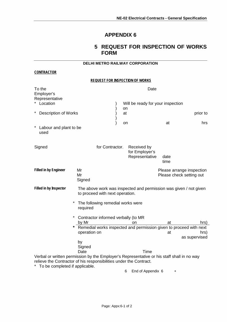
NE-02 Electrical Contracts - General Specification
Page: Appx:6-1 of 2
APPENDIX 6
5 REQUEST FOR INSPECTION OF WORKS FORM
DELHI METRO RAILWAY CORPORATION
CONTRACTOR
REQUEST FOR INSPECTION OF WORKS To the Employer’s Representative
Date
* Location ) Will be ready for your inspection ) on * Description of Works ) at prior to ) ) on at hrs * Labour and plant to be
used
Signed for Contractor. Received by for Employer’s
Representative
date
time Filled in by Engineer Mr Please arrange inspection Mr Please check setting out Signed Filled in by Inspector The above work was inspected and permission was given / not given
to proceed with next operation. * The following remedial works were
required
* Contractor informed verbally (to MR by Mr on at hrs) * Remedial works inspected and permission given to proceed with next operation on at hrs) as supervised by Signed Date Time Verbal or written permission by the Employer’s Representative or his staff shall in no way relieve the Contractor of his responsibilities under the Contract. * To be completed if applicable.
6 End of Appendix 6 ∗

NE-02 Electrical Contracts - General Specification
Page: Appx:6-2 of 2
Page Intentionally Blank

NE-02 Electrical Contracts - General Specification
Page: Appx: 7-1 of 2
Appendix 7 Not Used
* End of Appendix 7 *

NE-02 Electrical Contracts - General Specification
Page: Appx: 7-2 of 2
Page Intentionally Blank

NE-02 Electrical Contracts - General Specification
Page: Appx: 8-1 of 2
APPENDIX 8
FIRST AID REQUIREMENTS
1. Provisions by others (1) First aid bases will be located at the Contractor’s principal Works Areas. The bases will consist of a treatment room fitted with two treatment couches, a hand wash basin, sterilising equipment and lockable cupboards to contain sufficient medical supplies for the Contractor's workforce, the Employer's Representative's site supervisory staff, the Designated Contractors working in the area and any visitors to the Site. The first aid post will be air-conditioned, with cooling capability sufficient to maintain the temperature of the inside of the building at 20oC.
(2) A qualified doctor, nurse and assistant nurse will be in attendance at the first aid base during all times when work is being undertaken on the Site, including work by the Designated Contractors and periods when only emergency activities are being undertaken, such as during periods of inclement weather.
(3) A fully equipped ambulance and driver will be provided at the first aid base during all working hours. The ambulance will be equipped with emergency life support equipment suitable for application in construction site accidents.
2. Provisions by the Contractor
2.1 The Contractor shall supply portable first aid boxes maintained fully equipped at each local site offices and any work locations where 20 or more persons work at a time.
2.2 In each site office and work location at least one of the Contractor’s employees shall be trained in first aid and should be available at all working hours for purpose of attending to emergencies.
2.3 The Contractor shall be responsible for making his employees aware of the location and access route to the nearest first aid base and if necessary shall provide facilities for evacuating a workman by stretcher from the worksite.
2.4 The Contractor shall keep the first aid base personnel informed of the number and identity of staff working within the area of responsibility of each first aid base.
7 End of Appendix 8 ∗

NE-02 Electrical Contracts - General Specification
Page: Appx: 8-2 of 2
Page Intentionally Blank

NE-02 Electrical Contracts - General Specification
Page: Appx: 9-1 of 1
APPENDIX 9
WORKS AREAS
NOT APPLICABLE
1. Works Areas
a. Temporary occupation of land is governed by Part VI of land acquisition Act 1894 which limits occupation to 3 years.
b. Deleted.
c. Deleted.
(d) Deleted.
(e) Prior to the Works Area Handover Dates for returning any Works Area, the
Contractor shall carry out the following works:
(i) construct all Permanent Works within the area, to the extent defined in this Appendix, in accordance with the requirements of the Contract,
(ii) reinstate the area to the condition as close as possible to its condition
when it was taken over,
(iii) form the area to the approved lines and levels and carry out such other works as may be required by the Employer's Representative,
(iv) remove all rubbish, debris and other materials.
.
End of Appendix 9 ∗

DMRC/Contract NE-02/Vol-4/PS Page 5R
Space) (Indoor GIS type)
• Provision of Indoor GIS type Eight bays or as specified for the TSS (2 incoming, 1 coupler & 4 outgoing feeder bays for feeding the 25kV, single Phase AC Traction supply to feed OHE on the viaduct as per the detailed requirement.
• Provision of 9 Nos or as specified of 33 kV Indoor GIS type bays for feeders in the AMS for feeding Auxiliary supply to the ASS at stations (2 Nos), RSS auxiliary transformers (2 Nos), bus coupler (1 No.), incomers (2 Nos) and 2 spares. In addition to these 2 Nos of bus riser & PT panel will also be there as per requirement.
• Supply, Installation, Testing and Commissioning of two no. of 132 kV/33kV Auxiliary main transformers with NGR & On Load Tap Changers.
• Supply, Installation, Testing and Commissioning of two no. of 132 kV/27.5 kV traction transformers with O.L.T.C.
• Supply, Installation, Testing and Commissioning of lighting masts and lightening protection masts
• Supply, Installation, Testing and Commissioning of GIS type Auxiliary Main Substation.
• Provision of earthing grid and lightening protection system.
• The main protective relay shall be numerical type, IEC-61850 compliant. The Substation, Automation System (SAS for monitoring, control, protection, disturbance recording, event logging etc) shall be provided at each RSS integrating all the relays at 132 kV/33 kV/25 kV levels and the bay control units (BCUs) for 132 kV levels. The system architecture will be realized through IEC-61850 communication infrastructure. No external converters shall be used and provision shall be there for connectivity to the Operations Control Centre & BCC on IEC 60870-5-104/101 protocol.
• A redundant (hot-hot) full-fledged server shall be provided for each RSS.
• A wall display unit of adequate size shall be provided for operator to visualize the circuit condition vis-a vis the status of primary switch-yard equipments, while sitting at the control desk operator’s chair. This display unit shall connect to the station servers. Deleted
• The BCUs shall be provided on the 132 kV bays and housed in the indoor cubicles in the control room besides/ along with relay panels. The BCU shall have full fledged graphic display for the position of switching elements.
• For 33 kV & 25kV bays, the controls of CBs are desired to be achieved through the numerical protective relays combined with control functions or the independent BCUs. In case the combined protection and control IEDs are used and they shall have full fledged graphic display for display of position of switching elements. Also the local remote switching key pad shall be available.
• All the station auxiliaries, AC/DC supplies, system alarms shall be taken into the substation automation system.
• Supply of spare parts, tools and equipment for maintenance/repair facility of RSS cum TSS and AMS.
• Provision of 110 V DC battery banks (one main + one standby) and battery chargers for

RSS Contract: NE-02 Particular Specification – Installation and Construction
DMRC/Contract NE-02/Vol-4/PS Page 9R
3. SCHEDULES
3.1 SCHEDULE OF KEY DATES AND ACCESS DATES The following tables summarize the various Key Dates and Access Dates. All numbers below refer to weeks from Commencement date of the work.
RSS Tentative Date for Award of
LOA
Start of civil work
Start of submission of
vendor proposal for equipment drawing etc for
approval
Completion of delivery of
major materials at site like
Transformers,GIS bays,
Incoming Cables and
control panels
Completion of Erection of RSS
equipment, EHV cabling and all civil engineering
works
Testing, commissioning and charging of
both RSS including EHV
cabling
Integrated testing ,and Commissioning and Handing over
KD 1 KD 2 KD 3 KD 4 KD 5 KD 6
S1 - Sector-83 Noida
30.09.15 31.03.16 26 weeks
30.05.16 35 weeks
31.01.17 70 weeks
30.04.17 83 weeks
30.06.17 91 weeks
30.09.2017 104 weeks
S2 - Sector-153 Noida
30.09.15 31.10.15 4 weeks
31.12.15 13 weeks
31.07.16 44 weeks
31.10.16 57 weeks
30.11.16 61 weeks
30.06.2017 91 weeks
1. These dates are sacrosanct and are to be strictly adhered to. The tenderer may fill the other milestone dates accordingly. The
site will be available immediately after issue of LOA. 2. If the date of LOA varies due to some unforeseen reasons, other dates as mentioned above will advance/get postponed
accordingly. However, the ROD date is Firm. ROD date is 01.12.17
3.2 SCHEDULE OF ACCESS DATES All number refer to weeks from Commencement Dates of the works
Access Date Description of Stage Weeks
AD 1 Noida Sec-83 Access date for RSS-1 0
AD 2 Noida Sec-153 Access date for RSS-2 0
• Mean Access available from the date of issue of LOA.

Receiving Substations NE-02 – Particular Specification – Technical Descriptions
RC/Contract NE-02/Vol-4/PS Page 8R
1.3.2 132 KV supply
Nominal Voltage 132 kV Maximum Voltage Variations +10%, -15% of rated value Nominal frequency 50 Hz Maximum frequency variations
±3%
Short circuit Current 22 31.5 KA for 1 sec unless otherwise as specified in specifications
1.3.3 66 kV Supply Nominal Voltage 66 kV Maximum Voltage Variations +10%, -15% of rated value Nominal frequency 50 Hz Maximum frequency variations
±3%
Short circuit Current 20 KA for 1 sec unless otherwise as specified in specifications

Receiving Substations NE-02 – Particular Specification – Technical Descriptions
RC/Contract NE-02/Vol-4/PS Page 13R
2.1.1.1.3 Each Bus Coupler Bay (1 No.) consisting of;
Circuit Breaker – 1 No. Current Transformer – 2 Nos. Bus Disconnectors & Earth Switch – 2 Nos. Other items as required for connection to bus bars, cables etc. and for completing
the intent of work
2.1.1.1.4 Each Bus VT Module (2 No.) consisting of; Voltage Transformer – 1 No. Bus Earthing Switch – 1 No.
2.1.1.1.5 Bus bars for double bus arrangement. 2.1.1.1.6 New Gas charging equipment with gas cylinders for each set of the newly constructed
GIS substation covered in the scope of work - After commissioning this will become property of Employer. The contractor would be required to hand over them in proper working condition with enough gas for one charging of complete system.
2.1.1.1.7 EOT crane with VVVF drive for continuous operation for GIS equipment handling during installation, commissioning and maintenance etc. Crane lifting capacity shall be adequate to handle the heaviest package of GIS but shall not be less than 5 tonnes.
2.1.1.1.8 Supply, erection, testing and commissioning of all items of work required to make the HV bays (66 132 kV) fully functional.
2.1.1.1.9 Main features required 2.1.1.1.10 The 132 kV equipment shall be built according to the SF6 gas insulation technology. 2.1.1.1.11 132KV GIS as offered should be fully type tested as per latest IEC standards at the time
of submitting the bid. The bidder would be required to submit the detailed type test reports as per latest IEC standards in the event of an order.
2.1.1.1.12 The equipment installed shall offer all necessary facilities for equipping and connecting the equipments sections to follow, without entailing any shut down of equipment already in service.
2.1.1.1.13 In the event of arching in a compartment, the arches should not extend to the neighboring compartment. Any failure to the enclosure of the compartment shall not lead to damages in the neighboring compartments.
2.1.1.1.14 Suitable means of expansions should be provided in the metal enclosure and pipelines to absorb the actual thermal expansion and contraction of the SF6 equipment and to facilitate the alignment of switchgear assembly.
2.1.1.1.15 Internal insulation level between live parts and earth when the pressure of the gas goes to the atmospheric pressure should not be less than 1.2*132/1.732kV.
2.1.1.1.16 The metal enclosures for the SF6 gas insulated equipment modules shall be made from aluminum alloy.
2.1.1.1.17 GIS should be of modular design, and it should be possible to add feeder bays for two additional transformers, if required. The layout of GIS equipments and transformers should show space earmarked for the future provision.
2.1.1.1.18 GIS supplier should have minimum 5 years experience in design and manufacturing of similar GIS substations. This shall be explained in tenderer’s technical proposal. The tenderer will be required to explain availability of spares and service from technically

Receiving Substations NE-02 – Particular Specification – Technical Descriptions
RC/Contract NE-02/Vol-4/PS Page 14R
trained manpower. 2.1.1.1.19 The incoming 3 phase 132 kV single core cable feeders can be of minimum size of 630
Aluminum/800 mm2 (Copper) to 1200 mm2 (Aluminum)/1000mm2 Copper. The termination arrangement shall however be designed for two such cables, so that additional cables can be terminated later, if required. The outgoing connections from GIS shall be in gas filled enclosure, designed in such a way that vibration from GIS equipment and transformer are not transmitted to each other. The transformer feeder bays should have termination arrangements suitable for cable cross-section required as per current requirements of transformer. The terminations at transformers shall be of normal outdoor type with suitable cable connection from the GIS.
2.1.1.1.20 The Disconnectors and earthing switches shall be electrically and mechanically interlocked against mal-operation. Feeder earthing switch shall be fast acting type and isolated from earthed enclosures and shall permit testing of switchgear. It shall also be possible to carryout high voltage testing of cable cores without having to open the breaker assembly or SF6 chamber without disconnecting the cables. Suitable adapter for such testing should be provided. This adapter is to be quoted as a separate BOQ item in Item No. 35, Annexure Table - B: List of tools. For other routine maintenance also, dismantling of switchgear should be required.
2.1.1.1.21 The conductors/bus bars shall be of copper/ Aluminium and enclosure shall be made of Aluminum Alloy.
2.1.1.1.22 The gas barrier insulators shall withstand 1.5 times maximum rated pressure on one side and vacuum on the other side. All fixtures or nuts or instruments whose maintenance / opening would leak the SF6 gas should be clearly ear marked and distinctly identifiable.
2.1.1.1.23 All gas sampling shall be possible during normal operation and without loss of gas. 2.1.1.1.24 Loss of gas per annum shall not exceed 1% by weight in each compartment. 2.1.1.1.25 Adequate burden capacity shall be available in instrument transformers to permit
provision of additional test, protection on measuring instruments. The instrument transformer shall have separate metering cores to permit measurement of values of energy, power, current and voltage as per required accuracy, giving due consideration to the fact that load during initial stages may be much lower than designed capacity. The instruments shall also be sized and positioned so that a 5’-5’-6” height operator can read the instrument without additional support.
2.1.1.1.26 Clear visual indication of isolator and earthing switch, switch blade position, whether open or closed shall be provided.
2.1.1.1.27 Each component shall be modular and complete with ancillary equipment. 2.1.1.1.28 Circuit breaker shall be of single pressure interrupter. The moving and fixed contacts
shall be housed in the same interrupter chamber without any split so as not to affect the synchronism of three phases. The Operating Mechanism for the circuit breaker shall be Spring/Spring or to give highest reliability to the system, following loss of supply voltage the operating mechanism shall have local storage sufficiency for a duty cycle of O-CO without the need for recharging. The circuit breakers shall be provided with an “anti-hunting” coil for all commands going to the switchgear. All interlock and automatic systems within the actuation system shall be designed so that the circuit breaker executes operations only when it is in a position enabling to do so completely and reliably.
2.1.1.1.29 The isolators shall be fitted with a suitable actuation system operating simultaneously on all three poles, backed up by an emergency manual actuation in case of malfunction of the former. The isolators shall not change of position under the effect of electro dynamic

Receiving Substations NE-02 – Particular Specification – Technical Descriptions
RC/Contract NE-02/Vol-4/PS Page 18R
the 33 kV distribution network, through appropriate switchgear and protection arrangements. The AMS mainly comprises of: - 132KV/33KV Auxiliary Main Transformer
- 33 kV, GIS, SF-6 ,Indoor type switchgear including 33 kV Circuit Breakers , 33 kV busbars, 33 kV potential and current transformers as required, earth switches, protection relays, meters and all other components required for satisfactory operation of the switchgear.
- 33 kV / 415 V 200 100 kVA Auxiliary dry type transformers - 415 V AC Distribution Board - Battery, Battery chargers - 110 V DC Distribution Board - Interface cubicle to act as a link between AMS equipments and ‘GATEWAY’ To
SCADA - Interconnecting power and control cables.
2.1.5.1 AUXILIARY MAIN TRANSFORMER SCOPE
These specifications are applicable to Auxiliary Main Transformer of 3-phase 220/132/66KV primary voltage and 3-phase, 33 KV secondary voltage. Auxiliary Main Transformer shall be designed for outdoor installation and for operation at frequencies of 50 Hz. The Auxiliary Main Transformer shall be complete with all Parts, Fittings, and oil for the first filling, and accessories necessary for its efficient operation, including mounting frame work of steel. All such Parts, Fittings and Accessories shall be deemed to be within the scope of this Specification, whether specifically mentioned or not. The Auxiliary Main Transformer shall be of proven design.
2.1.5.1.1 Governing Specification The Auxiliary Main Transformers shall comply with the standards of the
International Electro Technical Commission (IEC60076) or equivalent Indian standards.
2.1.5.1.1.1 Standards The Auxiliary Main Transformer shall satisfy the requirements given below and shall also comply with standards in force when they are manufactured, particularly which are in the following table. (unless otherwise stipulated in the specifications, the latest version of the following standards shall be applicable): -
S. No. Specification No. Title of Specification 1. IEC:60076-1,2,3,4,5 &7 Power Transformer 2. IEC : 60214 Tap changer for power transformer 3 IEC 60296 Insulating oil for Transformer 4 IS335 Insulating oil for Transformer 5 IEC 60028 Conductor for Insulated cable
6 IEC 60137 Insulating Bushing for rated Voltage above 1KV

Receiving Substations NE-02 – Particular Specification – Technical Descriptions
RC/Contract NE-02/Vol-4/PS Page 35R
proposal along with the complete bill of materials. After awarding of contract, detailed dimensional drawing of the system complete bill of materials including location and size of plinth for cubicles and recommended capacity of oil soak-pit shall be submitted for purchaser’s approval. After approval 10 (ten) sets of all above drawings and 5 (five) sets of operation and maintenance instruction manual (bound) shall be submitted for purchaser’s use.
SPARES
One full set of spares nitrogen gas filled cylinder, 50 % of the installed no. of fire detectors (heat sensing element) shall be provided in addition to additional other recommended spares. The list of recommended spares is to be submitted along with the proposal of vendor approval..
2.1.5.1.21 Fiber Optic winding Hot Spot Temperature Monitor:-
Fiber optical winding hot spot temperature monitor to be provided with transformer windings connected in parallel of the winding temperature indicator to measure transformer‐winding hot spots in real time and activate control of the cooling system. The Fiber to be given high strength casing through rugged jacketing and fiber to be securely routed till the tank wall plate. Specification for Fiber Optic Temperature Measurement System. Fiber optic based temperature measurement of Oil and windings shall be done using Fiber Optic sensors meeting following criteria:
1. System shall be of proven technology. The temperature sensing tip of the fiber
optic shall be ruggedized. The probes shall be directly installed in each winding of power transformer to measure the winding hot spot and at the top oil temperature. There shall be at least 4 probes inside the transformer.
2. Out of the 4 probes one probe shall be used for top oil temperature
measurement and the balance will be placed in the LV, HV and Tap Changer winding (One probe per winding).
3. Probes shall be able to be completely immersed in hot transformer oil they
shall withstand exposure to hot vapour during the transformer insulation drying process, as part of Vacuum Phase Drying (VPD). The probes shall meet the requirement to eliminate the possibility of partial discharge in high electric stress areas in the transformer. Probes shall have certified Weidman testing for electrical parameters as per ASTM D‐3426 and ASTM D‐ 149 that is current (not more than 1 5 year old). Test results and studies to be submitted by the transformer manufacturer along with the first unit of a certain type of traction transformer.
4. Temperature range of the system should be up to +200°C without any need of
recalibration. Probes must connect to the tank wall plate with threaded connectors containing a Viton o‐ring to prevent against oil leakage.

Receiving Substations NE-02– Particular Specification – Technical Descriptions
DMRC/Contract NE-02/Vol-4/PS Page 37R
2.1.6 33 kV Switchgear
2.1.6.1 General AMS Switchgear 33kV switchgear for AMS which is directly connected to ASS will be GIS indoor type This 33kV equipment shall include Auxiliary 33kV cable bridge GIS type indoor cubicles
This bridge shall be divided into two half bridges, each one comprising of the following:
- 1 Auxiliary Bridge Circuit Breaker (LBCB) cubicle,
- 1 Auxiliary 33 kV cable Circuit Breaker (RCCB) cubicles
- 1 Low voltage Auxiliary Transformer Circuit Breaker (LVATCB) cubicle
- 1 spare circuit-breaker (LFCB) cubicles
- 1 Auxiliary circuit breaker for RSS located in/near depot.
All 33 kV circuit breaker shall be provided with one set of 3 phase 33 kV voltage transformer on cable side. These two half bridges shall be linked through
- 1 Coupling Circuit Breaker (LBCCB) cubicle
- 1 bus riser cubicle if required
The metal-enclosed switchgear shall be gas insulated and the circuit interrupting device shall be of vacuum type. The switchgear offered shall have a basic insulation level (BIL) of not less than 170kV peak. The switchgear shall be capable of operating in class B environment stipulated in clause 1.12 of General Specification.
The 33kV switchgear shall comply with the following IEC standards: 60044-2, 62271-103, 62271-200, 60376, 62271-1, 62271, 66044, 60028, 60044 and 62271-100.
2.1.6.2 Switch Gear Cubicles General Description
All non-welded assemblies shall be assembled by means of bolts and nuts with mandatory use of lock-washers. All panels, separating partitions, coupling modules and accessories shall be mounted similarly, in such a way so as to withstand indefinitely the vibrations transmitted, in particular by the resetting mechanism of the circuit-breakers and their actuation.

Receiving Substations NE-02– Particular Specification – Technical Descriptions
DMRC/Contract NE-02/Vol-4/PS Page 111R
(iii) Printouts of the maximum and minimum values and frequency of occurrence and duration of maximum and minimum values for each analogue parameter for each circuit in 24 hr period.
(iv) Provision shall be made for logging information about breaker status like number of operation with date and time indications.
(v) Equipment operation details shift wise and during 24 hours. (vi) Printout on adjustable time period as well as on demand for MW, MVAR, Current,
Voltage on each feeder and transformer as well as Tap Positions, temperature and status of pumps and fans for transformers.
(vii) Printout on adjustable time period as well as on demand system frequency and average frequency.
(viii) Reports in specified formats which shall be handed over to successful bidder. 3.5.3.2.7 Trend display (historical data)
It shall be possible to illustrate all types of process data as trends - input and output data, binary and analogue data. The trends shall be displayed in graphical form as column or curve diagrams with a maximum of 10 trends per screen. Adjustable time span and scaling ranges must be provided. It shall be possible to change the type of value logging (direct, mean, sum, or difference) on-line in the window. It shall also be possible to change the update intervals on-line in the picture as well as the selection of threshold values for alarming purposes.
3.5.3.2.8 Automatic disturbance file transfer All recorded data from the IEDs with integrated disturbance recorder as well as dedicated disturbance recording systems shall be automatically uploaded (event triggered or once per day) to a dedicated computer and be stored on the hard disc.
3.5.3.2.9 Disturbance analysis The PC-based work station shall have necessary software to evaluate all the required information for proper fault analysis.
3.5.3.2.10 IED parameter setting It shall be possible to access all protection and control IEDs for reading the parameters (settings) from a dedicated monitoring computer. The setting of parameters or the activation of parameter sets shall only be allowed after entering a password.
3.5.3.2.11 Automatic sequences The available automatic sequences in the system should be listed and described, (e.g. sequences related to the bus transfer). It must be possible to initiate pre-defined automatic sequences by the operator and also define new automatic sequences.
3.5.3.3 Gateway 3.5.3.3.1 Communication Interface
The Substation Automation System shall have the capability to support simultaneous communications with multiple independent remote master stations, The Substation Automation System shall have communication ports as follows:-
a) Two ports for simultaneous reporting to two masters, Operation Control Centre (OCC) at Shastri Park/Metro Bhawan, Ph-II OCC/Metro Bhawan, Ph-III OCC at rolling stock depot Greater NOIDA and BCC at RSS Sector 153.
b) One spare port for connecting to a third master if required in future 3.5.3.3.2 Communication Protocol
The communication protocol between IED’s and station HMI shall be on the global Automation standard IEC 61850 at inter bay level and shall be on IEC 870-5-/104 or existing compatible protocol for communication from local RSS to the OCC.

Receiving Substations NE-02– Particular Specification – Technical Descriptions
DMRC/Contract NE-02/Vol-4/PS Page 115R
a) Configuration Management b) Fault Management c) Performance Monitoring
This system shall be used for management of communication devices and other IEDs in the system. This NMS can be loaded in DR work-station and shall be easy to use, user friendly and menu based. The NMS shall monitor all the devices in the SAS and report if there is any fault in the monitored devices. The NMS shall
a) Maintain performance, resource usage, and error statistics for all managed links and devices and present this information via displays, periodic reports and on demand reports.
b) Maintain a graphical display of SAS connectivity and device status. c) Issue alarms when error conditions occurs d) Provide facility to add and delete addresses and links
3.5.5.2.4 The contractor shall provide each software in two copies in CD to load into the system in case of any problem related with Hardware/Communication etc.
3.5.6 Tests The substation automation system offered by the bidder shall be subjected to following tests to establish compliance with IEC 61850 for EHV sub station equipment installed in sheltered area in the outdoor switchyard an specified ambient conditions. Each IED/BPU/BCU should confirms to environment factor class 3C3 as per IEC 60721-3-3 for highly Polluted area.Relay Cards must have confirmed coating and confirming with IEC 60815 - 1996 and tested for H2S, So2 and mixed gas tests as per IEC 60068 - 1 & 2.
3.5.6.1 Type Tests: 3.5.6.1.1 Control IEDs and Communication Equipment
a) Power Input: (i) Auxiliary Voltage (ii) Current Circuits (iii) Voltage Circuits (iv) Indications
b) Accuracy Tests : (i) Operational Measured Values (ii) Currents (iii) Voltages (iv) Time resolution
c) Insulation Tests: (i) Dielectric Tests (ii) Impulse Voltage withstand Test
d) Influencing Quantities (i) Limits of operation (ii) Permissible ripples (iii) Interruption of input voltage
e) Electromagnetic Compatibility Test: (i) 1 MHZ. burst disturbance test (ii) Electrostatic Discharge Test

Receiving Substations NE-02– Particular Specification – Technical Descriptions
DMRC/Contract NE-02/Vol-4/PS Page 129R
Length marking: Length shall be marked with number at one meter intervals on the sheath. The energy and currents flowing through these cables, taking into account the worst electrical conditions * Bidder to furnish the data at the time of vendor approval or design approval stage.
4.2.6 Cable Laying
4.2.6.1 General The Cable Laying works shall be executed according to the rules of the Art pertaining to professional grade and generally in compliance with International Standards and Indian Standards " The digging done for cable laying work has to be suitably barricaded(size 2.5m *2.0m) to prevent any accident either to a road vehicle or to anyone else walking nearby.Cost for this shall be inbuilt in the milestone and no separate cost centre is specified. " The ground penetration radar survey shall be done for identifying the complete route map of the laid cables and also for identifying the existing utilities. The drawing shall be submitted by the contractor after laying of cable showing (X,Y,Z) co-ordinates i.e. the length, depth of cable of each cable, circuit wise, and clearly marking the details of the crossing (road/rail/other) , other utilities so as to clearly identify the route of the cable. In this, location of cable joints, SVL, pits etc. shall be clearly shown. While locating the SVLs, it should be ensured that SVLs are easily accessible for maintenance purpose.
4.2.6.2 Cable Laying 4.2.6.2.1 Cases
The EHV Cables between the Power Supply Authorities Substation and the DMRC RSS shall be laid in ground depending upon the site conditions of the selected route, any of the following paying conditions, may be adopted Case 1 & Case 1A – Not Used. Case 2 – Direct buried, with the cables (3) of each circuit laid in trefoil formation and side by side in one trench. Case 3 – Laid in underground duct. Case 4 – Laid in Trench less piping. Case 5 – Laid in abutment crossing Case 6 – Laid in Rail Track crossing Case 7 – Laid in Air, supported on piers/walls, for nallah-crossing
4.2.6.2.2 Details of Case 2 The laying conditions shall not be less than the following, for Case2.
- The trench for carrying the cables shall be at least 1.8m deep and 1.1m wide, which may vary as per site conditions with the approval of employer. Sufficient spacings should be maintained between two circuits as per the standards.
- Each of the 2 feeders shall consist of 3 single-core cables, and laid in trefoil formation. - Cables shall be laid at a depth of 1.7m below the ground level and over a 100 mm bed of
coarse sand. - Trench is to be filled with sand upto a depth of 1100mm below the ground level. - Cable shall be provided with the cover of concrete slab of 50mm thickness as per
drawing on the top as well as on the side of the laid cables in order to protect them from external ingress..
- Trench shall then be filled with earth upto a depth of 300 mm below the ground level. - A warning net shall then be laid above the earth filling (at 300 mm depth below the
ground level). A warning tape shall also be laid appropriately with Delhi Metro Rail Corporation marked on it.
- The top space of 300 mm shall be suitably filled with compacted Boulder and Bitumen/Jelly and given a final finish matching the surroundings.

Receiving Substations NE-02– Particular Specification – Technical Descriptions
DMRC/Contract NE-02/Vol-4/PS Page 130R
- The cables shall be tied through locking belts after 2 meters each for keeping the cables intact in case of trefoil formation. At locations, where there is change of level of laying, the cables shall be tied through locking belts after 1 meter each. These locking belts shall be strong enough to keep trefoil formation intact for entire life of cable. Heavy duty cable ties of width 30 mm (min) may also be used with the approval of engineer. The contractor can propose additional steps to ensure that cables remain in trefoil formation for life time.
- Identification tapes in continuous length should be provided at every 10 m for identification of cable circuits during maintenance / repair.
- When cables are laid in multiple trefoil formations the identification plates of aluminum of thickness not less than 2mm showing Feeder-1_Trefoil-1,Feeder-1_Trefoil-2,Feeder-2_Trefoil-1, feeder-2_Trefoil_2 shall be provided at every 10 meters.
4.2.6.2.3 Details of Case 3 In specific locations, the Employer may require the cables to be laid in underground ducts. The underground ducts shall be laid where road construction or formation is under construction or where water logging stretch is expected or as per the specific site condition. The general arrangement for such type of laying is shown as Case-3.
4.2.6.2.4 Details of Case 4 & 6 On all road/rail crossings and at other specific locations, cable laying shall be through trenchless drilling and the cables shall be passed through High Density Polyethylene (HDPE) or G.I. Pipes of appropriate diameter and thickness (Case-4). One spare HDPE pipe shall be laid for each feeder of 3 cables at the road/rail crossings.
4.2.6.2.5 Details of Case 5 & 7
On all abutment crossing or in air, supported on piers/walls, for nallah crossing and at other specific locations, cable laying shall be on the galvanized steel structures which can withstand wind velocity of 160kmph, supported on piers and have sufficient structural strength. The minimum average weight of zinc coating should be 1000g/m2 (RDSO). The cables should be well protected by providing GI sheet of thickness 8mm 14 gauge at-least fastened with nuts and bolts & tag welded on all sides to be protected from any pilferages. The arrangement shall render cable absolutely safe from any natural calamity. The cable shall not be exposed or get affected due to stray fire caused in the vicinity. In case of nallah crossing or crossing of water body, the erected structure shall not obstruct the water flow.The attention of bidder is specifically invited to the nallah crossing near Sector 82.
4.2.6.2.6 Spare Cables and Pipes When cables are laid in pipes, in addition to the pipes carrying the cables, at least one spare pipe (minimum 200 mm dia), without cable shall also be provided.
- In the case cables laid in underground ducts (Case 3) and cables laid in Trench less piping (Case 4), spare HDPE pipes, one for each circuit, shall be provided. In addition to pipes for power cables, 2 additional pipes, each of not less than 100 mm dia, shall be provided to carry control and monitoring cables, one operational and one spare (As indicated in the Interfacing Requirements, other cables such as pilot wire for pilot wire protection, if required, copper-core or optic fibre cables for control and monitoring, tele-communication etc, supplied by other Contractors shall be installed by the Contractor, in these pipes.
4.2.6.2.7 Cable protection at changeover location The cable path, when changing from buried in ground to underground duct or trenchless piping shall be adequately protected by proper sealing in concrete or other suitable

Receiving Substations NE-02– Particular Specification – Technical Descriptions
DMRC/Contract NE-02/Vol-4/PS Page 169R
5. EARTHING
5.1 EARTH MESH
5.1.1 General The Substation installation is subject to various faults such as operating over voltages, short circuits or lightning. In order to ensure protection to people and equipment, an Earth mesh, sized to limit the step and touch voltages below the dangerous values, shall be provided. The Earth Mesh design and installation shall be done in accordance with relevant provisions in IEEE 80-2000. Earth network should be designed taking into account conductors' temperature rise as regard to the faulty current levels. The RSS Contractor will have to provide a buried earth mesh in the Substation site. As far as the area over which the AMS & Control Room are situated, a separate earth mat suitably designed shall be provided under the building housing the AMS and Control room, apart from the Main Earth Mesh. The design of the Main Earth Mesh shall be done by the RSS Contractor, taking into account the site conditions (soil resistivity etc). The soil resistivity of sites is to be measured by contractor. The Main Earth mesh has to be linked, by means of suitable size of two copper strip to
- the earth mat under the AMS room - the buried rail/connecting strip for traction return current - Auxiliary Main Transformer (132kV/33kV ) neutrals - All equipment structures supporting 132kV, 33KV and 25kV equipments - Baffle walls between transformers. - Substation fencing - Lighting protection Earthing
5.1.2 Parameters affecting the design of earth mat Several variable factors are involved in the design of an Earth Mat at Substations. The following are some of the parameters which affect the design of earthing mat.
- Magnitude of fault current - Duration of fault - Soil resistivity - Resistivity of surface material - Earthing mat geometry - Material of earth mat conductor - Shock duration etc.
Earth mat for each substation has to be designed individually. The earthing mat has to be designed for the site conditions and shall ensure a low over all impedance (not more than 0.5 ohms) and a current carrying capacity consistent with the fault current magnitude.
5.1.3 Short Circuit Level The maximum short circuit power (Isc), considered for the whole substation area, for different voltage levels, are as follow: For 220kV 15000 MVA For 132kV 5000 7200 MVA For 66kV 2200 MVA

Receiving Substations NE-02– Particular Specification – Technical Descriptions
DMRC/Contract NE-02/Vol-4/PS Page 170R
5.1.4 Short circuit Current Accordingly, the short circuit current to be taken into consideration, for the Earth mesh design at Substations, shall be as follows :
For 220kV 40kA For 132kV 22 31.5kA For 66kV 20kA
5.1.5 Duration of fault current In India, the short term rating of most of the equipment is based on 1.0 second duration of fault. Therefore, 1 second may be adopted on the duration of fault in the calculations to determine the size of conductor for the earth mat. For the purpose of determining the safe step and mesh potentials, a duration of 0.5 second may be adopted. However, it has to be ensured that, on the basis of the protective gear and protective scheme provided, the fault is cleared within a period not exceeding 0.5 seconds. Determining the max Grid current (IG) The design value of the maximum grid current IG is given by the following formula IG = CP. Df . Ig Where, IG = Maximum grid current in Amperes CP= Corrective projection factor Df= Decrement factor Ig= Symmetrical grid current (RMS) in A Ig= Sf (3IO) Where, IO= Zero Sequence fault current
Sf= Current division factor (which relates to the magnitude of the portion of fault current to that of its portion flowing between the earth mat and surrounding earth, to the total fault current) The calculation of Sf is done by deriving an equivalent representation of the overheard ground wires, neutrals etc, connected to the earthing mat and then solving the equivalent circuits to determine the fraction of the total fault currents which flow between the mat and the earth and through the ground wire or neutrals. In practice, at the design stage, it will be fairly accurate to adopt a value of 0.5 for Sf to determine the fault current that flows through the grid to earth. Hence, the values of maximum grid current IG to be considered for design of Earth mat for Substations of different voltage levels, may be taken as follows : For 220 kV 0.5 x 40 = 20kA 132 kV 0.5 x 22 31.5= 11 16 kA 66 kV 0.5 x 20 = 10kA Important Note: The above values of max grid current are applicable only for determining the estimated values of Step and Mesh potentials. For determining the cross-sectional area of the earthing mat conductor, full fault current should be considered.

Receiving Substations NE-02– Particular Specification – Technical Descriptions
DMRC/Contract NE-02/Vol-4/PS Page 180R
The site will have to be cleared of all existing encumbrances, leveled and compacted. The finished ground level of the Substation site shall be above the Highest Flood Level (HFL) in the Region, to be ascertained by the Contractor and confirmed by the Local Authorities. In any case, the finished ground level shall be at least 60 cm above the main rail/ road level, near to the site. The compaction of soil shall be done in accordance with Standard Engineering practices and the site, after compaction shall be fit, without any detriment to support the heavy equipments, including transformers whose weight may be in the region of 100-110 tonnes, supported on 4 wheels which are spaced approximately 2.4 metres, running on a Broad Gauge (1.676m) track. During land preparation, if it becomes necessary to cut or transplant trees, it shall be done by the Contractor with the permission of Forest authorities/relevant authorities and with the approval of DMRC, strictly in accordance with the Local laws.
8.3 ACCESS ROADS The Contractor will be required to provide suitable access road to the Substation site, from the nearest main road, which has the necessary width and strength to carry the Power Supply equipments. The access road shall be black topped and transformer area of CC/RCC as per MOST specifications. For this purpose, the Contractor shall prepare the necessary design and calculations and submit them to the Employer/Employer’s Representative, for approval. On approval of designs and calculations, the contractor shall construct the approach roads as per approved designs. The approach roads should, at the minimum, be 5.0m wide and shall be able to support 100 – tonne trailers.
8.4 DRAINAGE Drainage of the Substation site shall be provided as per the best engineering practices, so as to prevent surface flooding and pooling of water. For this purpose, suitably designed drains and sumps shall be provided and if the water level inside the sump rises above a predetermined level, the sump water shall be arranged to be evacuated by means of suitable electric pumps fixed in the sump. In addition, suitable precautions shall also be taken to prevent transformer insulating oil from being discharged into the environment in the event of a ruptured transformer tank. This shall be realised by a retention tank for each transformer
- dimensioned in order to be able to contain the whole transformer oil; - laid below the transformer; - covered by a net to maintain a 5 cm width stone bed on which the oil might fall; - fitted with a beside extraction pit to be used for oil or raining water pumping.
The pumping shall be realised with a portable manual or electrical pump, which is to be stored in the maintenance room. The drainage system of RSS shall be connected to the local drainage system of the city by the RSS contractor with the permission of local authorities and it should be suitably protected to ensure prevention of back flow of outside drainage water to RSS.
8.5 AMS & CONTROL ROOM BUILDING
8.5.1 Detailed Design The RSS Contractor will have to submit the General Layout of the Control Room Building to accommodate all equipments required for completion of RSS work in such a way that total area of layout is not more than 2000sqm.The control room building shall be multistoried with the provision of one number six passenger lift and emergency stair

Receiving Substations NE-02– Particular Specification – Technical Descriptions
DMRC/Contract NE-02/Vol-4/PS Page 182R
The Contractor shall be responsible for the correctness and technical merits of his design, calculation, drawings, specifications and all other documentation.
All documents shall be delivered, submitted and approved by the Employer’s representative prior to start the construction work.
For each submission the Contractor will submit an original, 5 copies and the editable electronic file.
8.5.6 AMS & control room Building requirements
8.5.6.1 General While planning and constructing the buildings and rooms for electrical equipment, care must be taken to ensure that
- all operational requirements are satisfied - the rooms are free from groundwater and flooding - adequate accesses are provided for operation, transport and fire-fighting services - all applicable building regulations are respected - the building is structurally and functionally adequate in all respects and aesthetically
presents a good look. - The cable cellar is to be provided for GIS Building.
Materials used for the construction of the building shall be new and of good quality Materials shall be so chosen that the buildings when erected shall have good heat and sound insulation properties in normal conditions, as well as when combined with the heating or air-conditioning equipment installed by the Contractor. Height of the control room and AMS room shall be at least 4.8 mt. and that of the GIS room shall be at least 6.5 mts.
8.5.6.2 Walls, ceiling & floors Walls, ceiling and floors must be dry. Both external and internal walls shall be sound proof and 2 hours fire proof. The inside surfaces of the walls should be as smooth as possible to prevent dust deposits. The ceiling shall be finished in such a way that the equipments are not endangered by falling plaster. The floor surface must be easy to clean, pressure-resistant, non-slip and wear-resistant. Concrete floor with adequate strength to withstand movement of equipment/panels wear-resistant protective coating with ceramic tiles (non skidding type) is recommended for the control room. Attention must be paid to floor loadings when taking the equipment in and out. In front of control panels and Switchgear panels, insulated mats of approved design, shall be provided. The internal walls & ceiling shall be finished with plastic emulsion in control room and oil bound distemper in other rooms.In staircase granite shall be used. The hand rail of staircase shall be of stainless steel. All bricks to be used in RSS shall be of average compressive strength 100kg/cm2 and confirming to that required for IGBC certification
8.5.6.3 Doors and Windows Windows to each room shall be of an area, not less than 20% of the floor area. Windows must be so arranged that they can be opened and closed without any personnel coming dangerously close to any live parts. All windows of the ground floor building shall be fitted with burglar bars firmly attached to the structure of the building. The window shall be aluminium of appropriate section. All opening windows shall be fitted with locks. Internal doors shall be Three Two hours fire rated and shall be fitted with door closers, lever latches, mortise lock and keys.

Receiving Substations NE-02– Particular Specification – Technical Descriptions
DMRC/Contract NE-02/Vol-4/PS Page 194R
9. AMC The annual maintenance shall be in scope of the bidder. The scope shall include maintenance of all RSS equipments, control room building, and other civil structures and entire 132kV cabling system along with its accessories. This AMC shall start after the expiry of defect liability period of two years and shall be for a period of 3 years beyond DLP. The maintenance shall be carried out without hampering the operations of the metro system. The unit spare required for maintenance during AMC period beyond DLP will be either provided by DMRC or reimbursed, as applicable.However, cost of maintenance staff, supervisory staff and consumable, if any, is deemed to be included in the bid. The bidder shall include all costs involved in the AMC and nothing extra will be paid. The total cost for 3 years period shall be quoted and this will be fixed.
The bidder shall however also quote the price of AMC for five years beyond the 3 years of AMC mentioned above. This price shall however be quoted as a percentage basis taking the average per year price for the above quoted price for three years as a base.The Cost of AMC for this further 5 years will not be used for evaluating L-1 bidder. The price for AMC for 5 years beyond 3 years shall be taken as per clause 61 SCC with price variationclause on 3rd year AMC cost. Payment for AMC will be made on quarterly basis after completion of maintenance obligations by the Contractor. The AMC cost for 3 years shall be taken into account for tender evaluation purpose. However DMRC reserves the right to get it executed or not.The tenderer is bound to compulsorily quote for this item else the bidder shall be considered as non-responsive and his offer will be summarily rejected. The operation of Defect Liability period and/or AMCshall be done by representative of DMRC, or NMRC or any other agency as nominated by the employer which shall be binding on the contractor. The details of activities and required man power for executing AMC during DLP and beyond DLP is given in Annexure -2.

Contract NE-02 -Receiving Substations – Particular Specification – Technical Sheets
DMRC/Contract NE-02/Vol-4/PS/8B Page 4R
1. TRACTION TRANSFORMER
TRACTION TRANSFORMER 132 / 27.5 KV
INDICATIONS U VALUES Required Manufacturer Place of manufacture Port of embarkation Manufacturer drawing reference Standards IEC 60076, 60137,
60296 1) ELECTRICAL CHARACTERISTICS Type Outdoor Coupling I.i. Rated frequency Hz 50 Rated secondary power MVA 21.6/30 Cooling mode ONAN/ONAF Primary rated insulation voltage kV 145 Primary operating voltage kV 132 Rated Power frequency withstand voltage-one minute
kV r.m.s.
275
Rated Impulse withstand (1.2/50 micro second) kV peak 650 Primary line ends Secondary maximum non permanent voltage kV 29 Secondary rated voltage Without load kV 27.5 Rated power frequency withstand voltage for one minute secondary winding
kV
95
Rated impulse withstand (1.2/50 micro second) voltage for secondary winding
kV
250
Short-circuit voltage - On load tap changer on tap 1 - On load tap changer on median tap - On load tap changer on tap 16
% % %
Voltage drop at secondary winding - 4/4 of secondary load
V
Short circuit voltage % 13.8 12.5 Magnetic loading Tesla < 1.55 Permissible overload duration at - 50% - 100%
mn mn
15 5
Iron losses kW Copper losses - 4/4 of secondary load
kW
Short circuit current at secondary - On load tap changer on tap 1 - On load tap changer on median tap - On load tap changer on tap 16
kA kA kA
14
Transformation ratio - On load tap changer on tap 1 - On load tap changer on median tap - On load tap changer on tap 16
kV kV kV
112.2/27.5 132/27.5
145.2/27.5 Power at primary winding 4/4 of secondary load
MVA
30
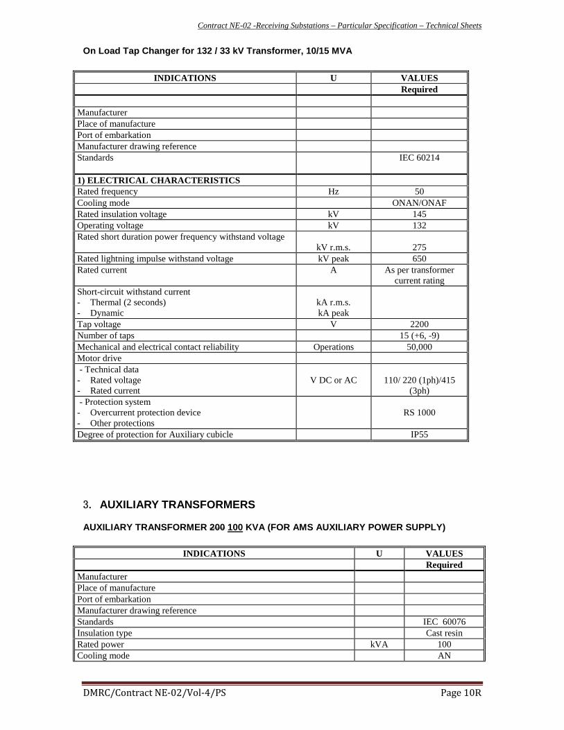
Contract NE-02 -Receiving Substations – Particular Specification – Technical Sheets
DMRC/Contract NE-02/Vol-4/PS Page 10R
On Load Tap Changer for 132 / 33 kV Transformer, 10/15 MVA
INDICATIONS U VALUES Required Manufacturer Place of manufacture Port of embarkation Manufacturer drawing reference Standards
IEC 60214
1) ELECTRICAL CHARACTERISTICS Rated frequency Hz 50 Cooling mode ONAN/ONAF Rated insulation voltage kV 145 Operating voltage kV 132 Rated short duration power frequency withstand voltage
kV r.m.s.
275 Rated lightning impulse withstand voltage kV peak 650 Rated current A As per transformer
current rating Short-circuit withstand current - Thermal (2 seconds) - Dynamic
kA r.m.s. kA peak
Tap voltage V 2200 Number of taps 15 (+6, -9) Mechanical and electrical contact reliability Operations 50,000 Motor drive - Technical data - Rated voltage - Rated current
V DC or AC
110/ 220 (1ph)/415
(3ph) - Protection system - Overcurrent protection device - Other protections
RS 1000
Degree of protection for Auxiliary cubicle IP55
3. AUXILIARY TRANSFORMERS
AUXILIARY TRANSFORMER 200 100 KVA (FOR AMS AUXILIARY POWER SUPPLY)
INDICATIONS U VALUES Required Manufacturer Place of manufacture Port of embarkation Manufacturer drawing reference Standards IEC 60076 Insulation type Cast resin Rated power kVA 100 Cooling mode AN

Contract NE-02 -Receiving Substations – Particular Specification – Technical Sheets
DMRC/Contract NE-02/Vol-4/PS Page 16R
- SF6 maximum pressure % - Secondary Cores Core 1
(Protection) 500-250/1A
cl PS Core 2
(Protection) 500-250/1A
cl PS Core 3
(Protection) 500-250/1A 50VA, 5P20
Actual transformation ratio A 500-250/1 Accuracy class Rated output VA 50 Short-circuit current allowable for 3 seconds kA 31.5 Permanent operation without danger In Overheating In Overcurrent class Total weight kg Overall dimension of one element Degree of protection for auxiliary circuit
THE VA OF CT MAY BE VARIED as per design
10. 132 KV VOLTAGE TRANSFORMER VTI-X AND VTC-X(GIS) INDICATIONS U VALUES
Required Manufacturer Place of manufacture Port of embarkation Manufacturer drawing reference Standards IEC 60186, 62271-
203 Type of voltage transformer Capacitive
Inductive Type Indoor Type of substation GIS - Primary insulation voltage kV 145 - Operating voltage kV 132 - Rated frequency Hz 50 - Rated short-time duration power frequency withstand voltage
kV
275
- Rated lightning impulse withstand voltage kV 650 Actual transformation ratio - Primary winding - Secondary winding
kV V
66/ 110/
Accuracy class 0.2 Rated output at power factor 0,8 lagging VA 200 Total weight kg Overall dimension of one element Degree of protection for auxiliary circuit
3
3

Contract NE-02 -Receiving Substations – Particular Specification – Technical Sheets
DMRC/Contract NE-02/Vol-4/PS Page 17R
11. 132 KV BUS BAR
INDICATIONS U VALUES Required Manufacturer Place of manufacture Port of embarkation Manufacturer drawing reference Type of substation Open Type of bus bar rigid bus Distance between phases m 1) Conductor Conductor type Al tube Conductor cross section mm² ** Conductor constitution - number of wires - wire diameter - total external diameter
mm mm
** Maximum current at 40°C above 45°C ambient temperature, without wind
A
**
Rated short-time withstand current (3 seconds) kA r.m.s. 22 Rated peak withstand current kA peak 50
** to be designed and built as per load current requirements commensurating the transformer maximum overload capacities
12. 132KV CABLES
S. No DESCRIPTION UNIT VALUE REQUIRED (II) Manufacturer
1. Cable size ** (minimum) Sq mm 630 2. Cable type AL/XLPE/Corrugated AL/PE 3. Voltage Grade (Uo/U (Um) KV 76/132(145) 4. Reference Standard IEC 60840 5. No and cross sectional area of conductor IC x 800 630 sq mm 6. Conductor material Aluminum 7. Shape Segmental compact stranded 8. Class Standard Class 2/IEC 228 9. Nominal diameter of conductor mm 33.5
10. Conductor Screen materials Extruded semi-conducting comp’d 11. Minimum thickness of conductor screen mm 0..95 12. Nominal thickness of insulation mm 19.0 13. Nominal diameter over insulation mm -- 14. Insulation screen material Extruded semi-conducting comp’d 15. Minimum thickness of insulation screen mm 0.8 16. W.B. Swellable tape Semi-conductive swellable tapes 17. Matallic sheath material Corrugated aluminum sheath 18. Nominal thickness of metallic sheath mm -- 19. Short circuit current rating (t=3.0 sec) KA >22 20. Outer sheath material HDPE (ST-7 type) 21. Nominal thickness of outer sheath mm -- 22. Minimum thickness of outer sheath mm --

Contract NE-02 -Receiving Substations – Particular Specification – Technical Sheets
DMRC/Contract NE-02/Vol-4/PS Page 21
Type Metal in air Nature of the active part Rated insulation voltage kV 24 Rated value Ω 20 Allowable tolerance on measurement (at 20°C in DC) % 5 Rated frequency Hz 50 Rated operating cycle
- thermal stabilisation at In=5A - Heating-up at I-20 A, 10 minutes - Heating-up at I-1000 A, 30 seconds
°C °C °C
Value of the resistance after operating cycle, at 45°C ambient temperature Ω
DIMENSIONAL CHARACTERISTICS Protection degree IP 55 Dimensions
- Length - Height - Depth - Weight
mm mm mm kg
Note: The above technical details are applicable to the Secondary Neutral Grounding Resistor, to be used
for secondary neutral earthing of 132kV/33kV Auxiliary Main Transformers.
16. PRIMARY NEUTRAL ISOLATOR FOR 132 KV / 33 KV TRANSFORMER
INDICATIONS U VALUES Required
Manufacturer Place of manufacture Standards IEC62271-102,
62271-1 Type outdoor - Number of pole 1 - Rated insulation voltage kV 108 132 -Operating voltage kV 72.5 -Rated short duration power frequency withstand voltage kV rms 140 -Rated short duration power frequency withstand voltage across
isolating distance
kV rms
160 -Rated lightning impulse withstand voltage kV peak 325 -Rated lightning impulse withstand voltage across isolating distance
kV peak
375 - Rated frequency Hz 50 - Rated current A 1000 - Rated short time withstand current (1 second) kA rms 20 - Rated peak withstand current kA peak 50
17. 6.2.1 SECONDARY NEUTRAL ISOLATOR FOR 132/33 KV TRANSFORMER
INDICATIONS U VALUES

Contract NE-02 -Receiving Substations – Particular Specification – Technical Sheets
DMRC/Contract NE-02/Vol-4/PS Page 34R
Rated output VA 60
30. 25KV CURRENT TRANSFORMERS
INDICATIONS U VALUES Required
Manufacturer Place of manufacture Standards IEC 44-1 Voltage / earth insulation kV 27.5 Frequency Hz 50 Type Cast resin GIS Erection Impulse Outdoor Indoor Rated Impulse withstand (1.2/50 micro second) kV peak 250 200 Rated Power frequency withstand voltage-one minute kV r.m.s. 95 Insulation withstand voltage (permanent) kV 29
Secondary Core
CT between Transformer and 25kV Busbar (TcTx)
Core 1 1600-800/1,cl PS
Core 2 1600-800/1, 5P15, 30VA Protection
class
Core 3 1600-800/1, 0.5CL, 20VA Measurement
class
CT between 25kV Busbar and OHE (TcCBxx)
Core 1 1600-800/1, 5P15, 30VA Protection
class
Core 2 1600-800/1, 5P15, 30VA Protection
class Withstand Over-current (1s /peaks) kA 20 / 41 Degree of protection for auxiliary circuit IP55
* THE VA OF CT MAY BE VARIED as per design
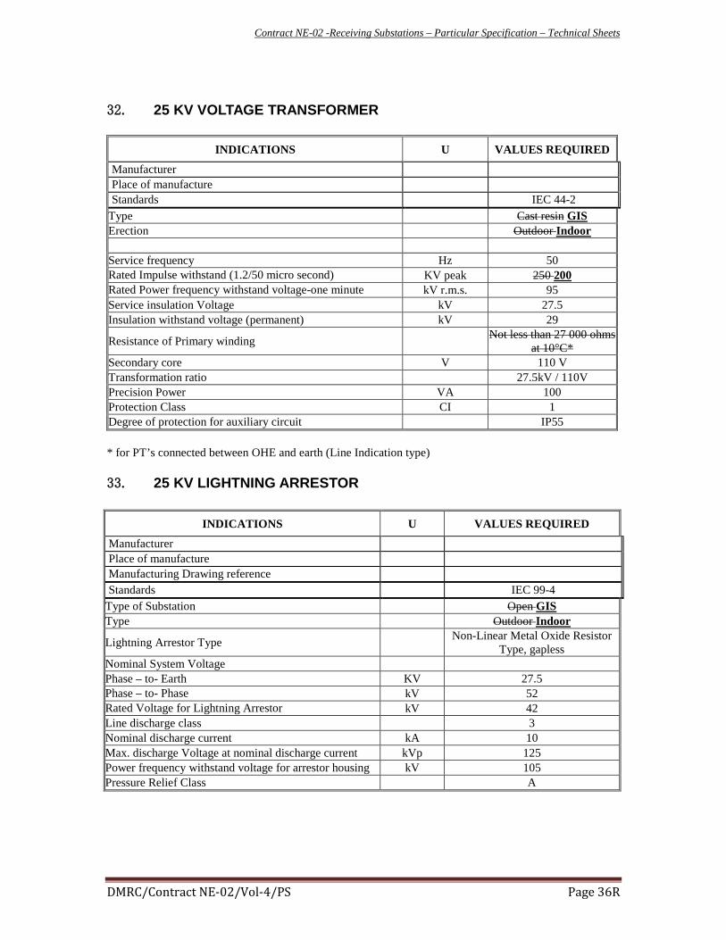
Contract NE-02 -Receiving Substations – Particular Specification – Technical Sheets
DMRC/Contract NE-02/Vol-4/PS Page 36R
32. 25 KV VOLTAGE TRANSFORMER
INDICATIONS U VALUES REQUIRED
Manufacturer Place of manufacture Standards IEC 44-2
Type Cast resin GIS Erection Outdoor Indoor Service frequency Hz 50 Rated Impulse withstand (1.2/50 micro second) KV peak 250 200 Rated Power frequency withstand voltage-one minute kV r.m.s. 95 Service insulation Voltage kV 27.5 Insulation withstand voltage (permanent) kV 29
Resistance of Primary winding Not less than 27 000 ohms at 10°C*
Secondary core V 110 V Transformation ratio 27.5kV / 110V Precision Power VA 100 Protection Class CI 1 Degree of protection for auxiliary circuit IP55 * for PT’s connected between OHE and earth (Line Indication type)
33. 25 KV LIGHTNING ARRESTOR
INDICATIONS U VALUES REQUIRED
Manufacturer Place of manufacture Manufacturing Drawing reference Standards IEC 99-4
Type of Substation Open GIS Type Outdoor Indoor
Lightning Arrestor Type Non-Linear Metal Oxide Resistor Type, gapless
Nominal System Voltage Phase – to- Earth KV 27.5 Phase – to- Phase kV 52 Rated Voltage for Lightning Arrestor kV 42 Line discharge class 3 Nominal discharge current kA 10 Max. discharge Voltage at nominal discharge current kVp 125 Power frequency withstand voltage for arrestor housing kV 105 Pressure Relief Class A

Contract NE-02 -Receiving Substations – Particular Specification – Technical Sheets
DMRC/Contract NE-02/Vol-4/PS Page 58
35.25 KV CB (GIS) INDICATIONS U VALUES
Required Manufacturer Place of manufacture Port of embarkation Manufacturer drawing reference Standards IEC 62271-1 ,
IEC 62271-100, 62271-203
Type INDOOR Substation type GIS Phase number 1 Rated frequency Hz 50 Rated voltage kV 27.5 Operating voltage kV 52 Rated current 2000A
Rated impulse level 200 kVp Rated power freq withstand voltage 95kV Breaking capacity 31.5KA Closing time 95 ms Opening time 65 ms Rated short-time withstand current (3 seconds) kA r.m.s. 16 Making capacity kA peak 40 Breaking mode: SF6 Rated operating cycle 0-.3sec-CO-3 mins-CO Rated auxiliary voltage Vdc 110 Out of load transformer current breaking capacity
A
Operating times - Opening actuation from current emission on the release coil up to - Separation of contacts (opening time) - Extinguishing of primary arc (breaking time at rated breaking capacity)
ms
ms

Contract NE-02 -Receiving Substations – Particular Specification – Technical Sheets
DMRC/Contract NE-02/Vol-4/PS Page 59
36. 25 KV ISOLATOR (GIS) INDICATIONS U VALUES
Required Manufacturer Place of manufacture Port of embarkation Manufacturer drawing reference Standards IEC 62271-1, 62271-
102, 62271-203 Type INDOOR Substation type GIS Number of phases 1 Two rotating columns Rated frequency Hz 50 Rated insulation voltage kV Operating voltage kV 27.5 Rated short duration power frequency withstand voltage
kV r.m.s. 95
Rated lightning impulse withstand voltage kV peak
200
Rated short duration power frequency withstand voltage across isolating distance
kV r.m.s.
Rated lightning impulse withstand voltage across isolating distance
kV peak
Insulation medium SF6 Rated current A 2000 Rated short-time withstand current (3 seconds) kA r.m.s. 31.5 Rated peak withstand current kA peak Rated auxiliary voltage Vdc 110 Rated control motor auxiliary voltage Vdc 110 2) EARTHING ISOLATOR Electrical values As above Making capacity

Contract NE-02 -Receiving Substations – Particular Specification – Technical Sheets
DMRC/Contract NE-02/Vol-4/PS Page 60
37. 33KV CABLES Sl. No. Description Unit Values
1 Manufacturer 2 Cable Size Sq mm 95 3 Cable type Copper/XLPE/PVC 4 Voltage Grade (U0/U (U2) KV 18/30 5 Reference Standard IEC 60502 6 No. and cross sectional area of conductor 3C x 95 sq mm 7 Conductor Material Copper 8 Shape Circular compact stranded 9 Class/Standard Class 2/ IEC 228
10 Nominal Diameter of Conductor mm 11 Conductor Screen materials Extruded semi-conducting com'd 12 Nominal thickness of conductor screen mm 13 Insulation material XLPE 14 Nominal thickness of insulation mm 15 Nominal diameter over insulation mm 16 Insulation screen material (Non-metallic) Extruded semi-conducting com'd 17 Nominal thickness of insulation screen mm 18 Insulation sceen material (metallic) Copper wires 19 Nominal thickness of tape mm 20 No. and Diameter of wires No. /mm - 21 Cross sectional area spmm 22 Outer sheath material Flame retardent polyvinyl chloride 23 Nominal thickness of outer sheath mm 24 Nominal overall diameter (± 2mm) mm 25 Minimum bending radius mm 26 Max. D. C. Conductor resistance at 20oC 0/km 27 Star reactance per phase at 50 Hz 0/km 28 Capacitance per phase uF/km 29 Charging current per phase at U0, 50 Hz A/km 30 Max. Current rating in air A 31 Max. Current rating in Ground A 32 Max. Conductor temperature on continuous 90 33 Max. conductor temperature in short Circuit 250 34 Max. short Circuit current rating
t = 0.1 sec KA t = 0.2 sec KA t = 0.5 sec KA t = 1.0 sec KA

Contract NE-02 -Receiving Substations – Particular Specification – Technical Sheets
DMRC/Contract NE-02/Vol-4/PS Page 61
38. 3.3KV CABLE GTP Sl. No. Description Unit Values
1 Manufacturer 2 Cable Size Sq mm 240 3 Cable type Copper/XLPE/PVC 4 Voltage Grade (U0/U (U2) KV 1.9/3.3 KV 5 Reference Standard IEC 60502-1 6 No. and cross sectional area of conductor 240 sq mm 7 Conductor Material Copper 8 Shape Circular compact stranded 9 Class/Standard Class 2/ IEC 228
10 Nominal Diameter of Conductor mm 11 Conductor Screen materials Extruded semi-conducting com 'd 12 Nominal thickness of conductor screen mm 13 Insulation material XLPE 14 Nominal thickness of insulation mm 15 Nominal diameter over insulation mm 16 Insulation screen material (Non-metallic) Extruded semi-conducting com 'd 17 Nominal thickness of insulation screen mm 18 Insulation sceen material (metallic) Copper wires 19 Nominal thickness of tape mm 20 No. and Diameter of wires No. /mm 21 Cross sectional area Sq mm 240 22 Outer sheath material Flame retardent polyvinyl chloride 23 Nominal thickness of outer sheath mm 24 Nominal overall diameter (± 2mm) mm 25 Minimum bending radius mm 26 Max. D. C. Conductor resistance at 20oC 0/km 27 Star reactance per phase at 50 Hz 0/km 28 Capacitance per phase uF/km 29 Charging current per phase at U0, 50 Hz A/km 30 Max. Current rating in air A 31 Max. Current rating in Ground A
32 Max. Conductor temperature on continuous
90
33 Max. conductor temperature in short Circuit
250 34 Max. short Circuit current rating
t = 3 sec KA As per specification

Receiving Sub -station Contract NE-02– Particular Specification – DLP/AMC of RSS
Annexure-2
SCOPE OF WORK FOR DLP/AMC of RSS
During Defect Liability Period /Annual Maintenance contract, Contractor shall
depute dedicated manpower round the clock in shifts prescribed in Table 1 at
designated place as agreed by Employer for attending breakdowns and
preventive maintenance activities. This shall be read in conjunction with Sub
clause 10 of SCC applicable for DLP and AMC as well. This excludes the
responsibility of the contractor during DLP defined in Tender Documents.
Table 1
S. No. Staff Designation No. of persons to
be deployed Min. Qualification
1 Sr. Engineer 1
Degree with 5 yrs.
Experience of similar
nature
2 Field Engineer 1 for each RSS
Degree with 3 years similar
Exp./ Diploma with 5 years
similar Exp.
3 Skilled 1 per shift ITI with 3yrs. Similar Exp.
4 Un-skilled 1 per shift -
Contractor shall set-up corresponding stores, repair shops, which includes
furniture, material racks ,staff cup-boards, tools instruments, material handling
instruments, communication instruments, material consumable etc.
Manpower mentioned above shall be able to perform duties as follows:
Duties of Senior Engineer / RSS
He/She shall be in-charge of Contractor’s RSS maintenance team responsible for
Safe, efficient maintenance of RSS installation at depot and mainline. He/She
should be fully conversant with the layout of RSS and also the rules and
procedures laid down for efficient maintenance of RSS and safe working on RSS.
In particular he shall:

Receiving Sub -station Contract NE-02– Particular Specification – DLP/AMC of RSS
1. Supervise the preventive and corrective maintenance of installations
under his charge in accordance with the standard and prescribed
schedules, to keep them fully serviceable all times and in a state of good
repair. To ensure proper record of preventive and corrective maintenance
of all installations in his control and submit monthly report to Employer
with completion and next due dates (Equipment wise):
2. Ensure advance planning of Preventive maintenance with a view to avoid
RSS failures and requirement of power blocks for RSS maintenance based
on the work done in consultation with the OCM through CTPC and ensure
completion of work within the time allotted.
3. Carry out detailed inspections of RSS under his control to cover the entire
section once in two months and submit the inspection report to Employer
without fail. To carry out all necessary inspections of his assets as per
the statuary requirement or otherwise and shall notify and rectify any
defects / deficiencies found during such inspections.
4. Scrutinize daily reports and other defects on RSS, as well as reports from
TPC inspections reports of Employer and arrange prompt rectification of
defects pointed out and report compliance to Employer and ensure their
implementation.
5. Instruct, train and supervise staff under his control and ensure that they
shall operate and maintain the equipment properly and in particular do
actually observe all prescribed rules and regulations, Joint Procedure
orders issued from time to time , safety precautions, SHE policy laid
down, to ensure proper training of all the staff working under him, ensure
Personnel Protective Equipment (PPE) while working on the system for self
and working staff as well.
6. Ensure that special testing instruments tool and equipments , for
maintenance of RSS are properly cared for and maintained in proper
condition.
7. Ensure that special tools and instruments provided for maintenance and
testing of all installations are carried for corrective and preventive
maintenance, their timely calibration, storing at proper place etc. He shall
ensure that other safety equipment including bonding and earthing are
functioning effectively.
8. Keep Employer fully informed of all-important developments and seek
their guidance when required.
9. Ensure proper upkeep of drawing, manuals and other all relevant
literature as per laid-down conditions of contract agreement.
10. Check the work done by maintenance gangs under him to ensure the
quality work and that compliance with prescribed schedules is adhered to.
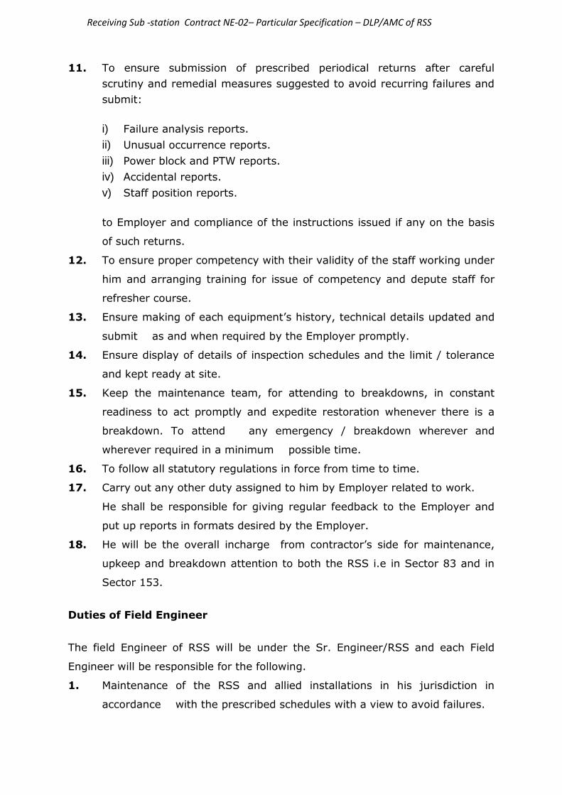
Receiving Sub -station Contract NE-02– Particular Specification – DLP/AMC of RSS
11. To ensure submission of prescribed periodical returns after careful
scrutiny and remedial measures suggested to avoid recurring failures and
submit:
i) Failure analysis reports.
ii) Unusual occurrence reports.
iii) Power block and PTW reports.
iv) Accidental reports.
v) Staff position reports.
to Employer and compliance of the instructions issued if any on the basis
of such returns.
12. To ensure proper competency with their validity of the staff working under
him and arranging training for issue of competency and depute staff for
refresher course.
13. Ensure making of each equipment’s history, technical details updated and
submit as and when required by the Employer promptly.
14. Ensure display of details of inspection schedules and the limit / tolerance
and kept ready at site.
15. Keep the maintenance team, for attending to breakdowns, in constant
readiness to act promptly and expedite restoration whenever there is a
breakdown. To attend any emergency / breakdown wherever and
wherever required in a minimum possible time.
16. To follow all statutory regulations in force from time to time.
17. Carry out any other duty assigned to him by Employer related to work.
He shall be responsible for giving regular feedback to the Employer and
put up reports in formats desired by the Employer.
18. He will be the overall incharge from contractor’s side for maintenance,
upkeep and breakdown attention to both the RSS i.e in Sector 83 and in
Sector 153.
Duties of Field Engineer
The field Engineer of RSS will be under the Sr. Engineer/RSS and each Field
Engineer will be responsible for the following.
1. Maintenance of the RSS and allied installations in his jurisdiction in
accordance with the prescribed schedules with a view to avoid failures.

Receiving Sub -station Contract NE-02– Particular Specification – DLP/AMC of RSS
2. Submission of the requirements of power blocks for RSS maintenance, in
Co-ordination with other departments concern as far as possible, so as to
take maximum advantage of Non traffic hours.
3. Detailed inspection of RSS under his charge as indicated in inspection
schedule.
4. Scrutiny of daily reports of defects and take prompt action to rectify the
defects brought out.
5. Close supervision of the maintenance gang under his control to ensure a
high standard of work and compliance with prescribed schedules. Also
convey each and every preventive and corrective maintenance progress
himself to CTPC/TPC as well as it should be written in the progress
register.
6. Keeping the team under his control in readiness to deal with breakdowns
and take prompt action to attend any failure and breakdowns following all
safety rules and regulations.
7. Guidance to the maintenance staff for the proper execution of work in
accordance with standing instructions.
8. Ensuring that tools and equipments under his charge are properly cared
for and maintained in proper condition.
9. Keeping watch and taking necessary and timely action to recoup spares
required for the system.
10. Preparation and submission of periodical reports and returns to Sr. Engr.
11. Keeping Employer informed of all important developments and seeking
their guidance when required.
12. Ensuring proper cleaning of each equipment.
13. Keeping proper records of all reference drawing, manuals, maintenance
schedule etc. for proper operation and maintenance of equipments.
14. Ensuring safe working by maintenance personnel at site while doing of
maintenance of equipments.
15. Ensuring proper competency of the maintenance personnel before
commencement of maintenance activity.
16. Ensuring periodical checking / inspections of all testing tools, safety
equipments and measuring equipments etc. timely and their
rectification of deficiencies / defects notices if any and maintaining their
proper records.
17. Carry out any other duty assigned to him by Employer related to work.
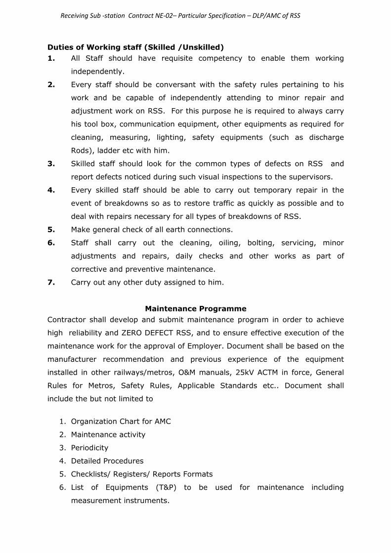
Receiving Sub -station Contract NE-02– Particular Specification – DLP/AMC of RSS
Duties of Working staff (Skilled /Unskilled)
1. All Staff should have requisite competency to enable them working
independently.
2. Every staff should be conversant with the safety rules pertaining to his
work and be capable of independently attending to minor repair and
adjustment work on RSS. For this purpose he is required to always carry
his tool box, communication equipment, other equipments as required for
cleaning, measuring, lighting, safety equipments (such as discharge
Rods), ladder etc with him.
3. Skilled staff should look for the common types of defects on RSS and
report defects noticed during such visual inspections to the supervisors.
4. Every skilled staff should be able to carry out temporary repair in the
event of breakdowns so as to restore traffic as quickly as possible and to
deal with repairs necessary for all types of breakdowns of RSS.
5. Make general check of all earth connections.
6. Staff shall carry out the cleaning, oiling, bolting, servicing, minor
adjustments and repairs, daily checks and other works as part of
corrective and preventive maintenance.
7. Carry out any other duty assigned to him.
Maintenance Programme
Contractor shall develop and submit maintenance program in order to achieve
high reliability and ZERO DEFECT RSS, and to ensure effective execution of the
maintenance work for the approval of Employer. Document shall be based on the
manufacturer recommendation and previous experience of the equipment
installed in other railways/metros, O&M manuals, 25kV ACTM in force, General
Rules for Metros, Safety Rules, Applicable Standards etc.. Document shall
include the but not limited to
1. Organization Chart for AMC
2. Maintenance activity
3. Periodicity
4. Detailed Procedures
5. Checklists/ Registers/ Reports Formats
6. List of Equipments (T&P) to be used for maintenance including
measurement instruments.

Receiving Sub -station Contract NE-02– Particular Specification – DLP/AMC of RSS
7. Precautions
8. Any other formats
9. Responsibilities.
Maintenance activities are broadly categorized as Follows:
A) Preventive Maintenance
B) Corrective Maintenance
RSS is play a vital role in the MRTS project and feeding power to OHE and other
auxiliary services are most important aspect. It is necessary to maintain the RSS
in perfect condition through proper checks on its geometry and all parameters
adopted in the design.
Check sheet for maintenance of RSS equipments are given in the subsequent
paras. Contractor has to follow all the check sheet and arrange required tools etc
for proper maintenance of RSS. .

Receiving Sub -station Contract NE-02– Particular Specification – DLP/AMC of RSS
DMRC Checksheet No.
O&M/Traction/RSS/CS/CB-132kV/01
CHECK SHEET FOR MAINTENANCE OF 132 KV Circuit Breaker
S.No. TASK Half Yearly Yearly
1 Date
2 Location
3 Equipment No.
4 Obtain power block and open the cover of control box. Clean accumulated dust by vacuum cleaner. Also clean the sight glass.
5
Check for moisture entry inside the box. Examine the door gasket and bellows of
transmission rod for any damage, replace if required
6 Check availability of handle, fixed inside the
door panel, for manual spring charging.
7
Check the operation manually as well as electrically in local and remote mode, keeping
the front door open, observe whether the mechanism functions smoothly without any rubbing or obstruction.
8 Check the working of counter and record the counter reading.
9 Check working of semaphore indicator for
open/close indication
10
Verify from SCADA status, the change of
position of local/remote switch and Open/Close status.
11 Check the working of heater.
12
Check electrical interlocking between CB and associated isolators both locally & remotely.
Isolators should not operate when CB is in closed condition.
13 Check all electrical connections of control
panel for tightness.
14
Check the bushing insulator for any chipping and flash mark and clean with cotton cloth.
Anti track paint should be applied on chipping/Flash marks.

Receiving Sub -station Contract NE-02– Particular Specification – DLP/AMC of RSS
15
Check & record SF6 gas pressure from density monitor. If low indication is there check for any gas leakage by SF6 Leakage detector. Top
up gas, if required (Normal range : CGL-5.5-6 BAR, ABB-6.2-7 BAR)
16 Check functioning of SF6 Low pressure alarm in SCADA by shorting relevant contacts(as per
wiring diagram).
17 Check the transmission rod for any looseness. Tighten, if required
18 Apply touch up paint in case of rusting, found inside or outside the control box.
19
Lubricate the moving parts. A very thin layer of Mobil 28 grease shall be rubbed on the
sliding surface of the moving parts viz. Cam, Cam wheel, Worm wheel, transmission roller,
transmission cam, bearing.
20 Measure resistance of opening/closing coil by multimeter (25 to 30 ohm).
X
21
Check the IR value of the 110V DC motor with 500 volt meggar (min. value - 1 mega ohm).
Clean the commutator with muslin cloth. Examine carbon brushes for any damage.
X
22
Check the condition of Bi-Metallic strip provided between connecting plate & bus bar
connector for any sulphation. Replace, if required.
X
23 Check the earth strip connections for tightness.
24 Check shock absorber for any movement & oil leakage.
25 Check nut & bolts of support structure for tightness.
26 Check Remote Operation by TPC before cancellation of Power Block

Receiving Sub -station Contract NE-02– Particular Specification – DLP/AMC of RSS
List of Tools for 132 kV Breaker Maintenance
Sr.No. Tools
1 Digital Multimeter
2 Blower (Single phase 220V)
3 Vacuum cleaner (Single phase 220V)
4 Megger (500V)
5 SF6 Gas leakage detector
6 SF6 Gas filling Kit
7 Rechargeable Torch
8 Electrician Knife
9 Adjustable Spanner
10 "D" Spanner set ( 6-7 to 30-32 no.)
11 Ring Spanner ( 5-6 to 30-32)
12 Hexagonal Spanner Set (5-6 to 20-22)
13 Screw Wrench 12" (01 no.)
14 Measuring tape (10m)
15 Allen key set
16 Combination plier 6"(Standard, nose & Long)
17 Round Nose Plier 6"
18 Hammer (200 gm & 800 gm)
19 Hacksaw frame with blade
20 Screw Driver Set big
21 Screw Driver Set (small for control wiring)
22 Philip Screw Driver set
23 Long Screw Driver 12" & 15"
24 Round File 6"
25 Flat file 6"
26 Flat file 12"
27 Chisel 6"
28 Center Punch 6"
29 Pipe Wrench 12"
30 Line Tester
Consumable spares
31 Grease (Mobil 28)
32 Cotton cloth
33 Muslin cloth

Receiving Sub -station Contract NE-02– Particular Specification – DLP/AMC of RSS
34 Insulating Tape (PVC)
35 Bimetallic strip
36 SF6 Gas
37 Antitrack Paint
38 Enamel paint
DMRC Check sheet no.
O&M/Traction/RSS/CS/HT Bay/01
Check sheet for HT Bay (220,132,66 kV)
S No
Check sheet for LA maintenance Quarterly
1
Check whether ammeter is working or not before
taking power block, there should be some defection due to leakage current.
2 Obtain power block & provide earthing rod
3
Clean the porcelain insulator with dry cotton cloth. Check for any flash, crack and chipping. Anti track
paint should be applied on chipping/flash marks.
4
Check tightness of all nut & bolts of bus bar
connector.
5 Check earthing connection for tightness.
S
No
Checksheet for bus bar connector, post insulator and
cable termination maintenance Quarterly
1
Clean the post insulator & cable termination with dry cotton cloth. Check for any flash, crack and chipping.Anti track paint should be applied on chipping/flash marks.
2 Check tightness of all nut & bolts of bus bar connector and cable terminations.

Receiving Sub -station Contract NE-02– Particular Specification – DLP/AMC of RSS
List of Tools for HT Bay Maintenance
Sr.No. Tools
1 Digital Multimeter
2 SF6 Gas leakage detector
3 SF6 Gas filling Kit for SF6 type CTs
4 Rechargeable Torch
5 Electrician Knife
6 Adjustable Spanner
7 "D" Spanner set ( 6-7 to 30-32 no.)
8 Ring Spanner ( 5-6 to 30-32)
9 Combination plier 6"(Standard, nose & Long)
10 Hammer (200 gm & 800 gm)
11 Screw Driver Set big
12 Line Tester
Consumable spares
13 Bimetallic strip
14 Cotton cloth
15 Insulating Tape (PVC)
16 HT Tape
17 SF6 Gas
18 Anti Track paint
19 Enamel Paint

Receiving Sub -station Contract NE-02– Particular Specification – DLP/AMC of RSS
DMRC Checksheet no.
O&M/Traction/RSS/CS/LT
Bay/01
Check sheet for TSS Bay (25 kV)
S
No Check sheet for LA maintenance Quarterly
1 Check whether ammeter is working or not before taking power block, there should be some defection due to leakage current.
2 Obtain power block & provide earthing rod
3
Clean the bushing with dry cotton cloth. Check for any flash, crack and chipping.Anti track paint should be applied on chipping/flash marks.
4 Check tightness of all nut & bolts of bus bar connector .
5 Check earthing connection for tightness.
S No
Checksheet for PT maintenance Quarterly
1 Clean the insulator with dry cotton cloth. Check for any flash, crack and chipping. Anti track paint should be applied on chipping/flash marks.
2 Check tightness of all nut & bolts of bus bar connector and secondary terminals.
3 Check earthing connections for tightness.
4 Check PT fuse for healthiness
S No
Check sheet for cast resin CT maintenance Quarterly
1 Clean the bushing with dry cotton cloth. Check for any flash, crack and chipping. Anti track paint should be applied on chipping/flash marks.
2 Check tightness of all nut & bolts of bus bar connector and secondary terminals.
3 Check bimetallic strip for any sulphation, replace if required.
4 Check earthing connections for tightness.
S
No
Check sheet for bus bar connector, post insulator and
cable termination maintenance Quarterly
1 Clean the post insulator with dry cotton cloth. Check for any flash, crack and
chipping. Anti track paint should be applied on chipping/flash marks
2 Check tightness of all nut & bolts of bus bar connector and cable terminations.

Receiving Sub -station Contract NE-02– Particular Specification – DLP/AMC of RSS
List of Tools for LT Bay Maintenance
Sr.No. Tools
1 Digital Multimeter
3 Rechargeable Torch
4 Electrician Knife
5 Adjustable Spanner
6 "D" Spanner set ( 6-7 to 30-32 no.)
7 Ring Spanner ( 5-6 to 30-32)
8 Combination plier 6"(Standard, nose & Long)
9 Hammer (200 gm & 800 gm)
10 Screw Driver Set big
11 Line Tester
Consumable Spares
12 Bimetallic strip
13 Cotton cloth
14 Insulating Tape (PVC)
15 HT Tape
16 Anti Track Paint

Receiving Sub -station Contract NE-02– Particular Specification – DLP/AMC of RSS
DMRC Checksheet no.
O&M/Traction/RSS/CS/Motorised Isolator/01
CHECHKSHEET FOR MAINTENANCE OF MOTORISED ISOLATOR
S.No. TASK Quarterly Yearly
1 Date
2 Location
3 Equipment No.
4 Obtain power block & provide earthing rod
5
Check the operation electrically in local and
remote mode ,keeping the front door open:
a.Observe whether the motor gear mechanism functions smoothly without any rubbing or
obstruction. b. Male and female contact should be in
aligned position when isolator is colosed, if not then adjust limit switch in control box.
6
Check electrical interlocking between Isolator and associated CB both locally & remotely.
Isolators should not operate when CB is in
closed condition.
7
Press Manual push button & remove castle
key. Isolator should not operate electrically after removal of castle key.
8
Check operation with handle after placing castle key at other slot provided for opening
of door slot for insertion of handle.
9 After checking above operations, make sure
that power circuit of motor is switched off.
10 Clean the control box with blower.
11 Check all wiring connection for any looseness and tighten if required.
12 Check nut and bolts for any looseness and tighten if required.

Receiving Sub -station Contract NE-02– Particular Specification – DLP/AMC of RSS
13
a) Check the clearance between male and female blades in open condition it should be
≥ 50 cm for vertical break isolators. Note the distance between male and female contact
should be measured perpendicularly in case of verticle break isolator.
b) Check the alignment of moving contact in
case of horizontal break isolator. It should be perpendicular with respect to busbar in open
condition of isolator.
14
Check the pedestal insulator for any chipping
and dust. Clean with dry cotton cloth. In case of chipping apply anti track paint.
15
Check alignment of arcing horn provided on
male and female contact of isolator. Adjust if required.
16
Check proper alignment of male and female contact on fixed as well as moving end. There
should be no airgap between male contact and
female spring leaf in close condition of isolator.
17
Clean the contact with cotton cloth and apply thin film of petrollium jelly to the contact
surfaces. Remove excessive jelly.
18
Grease the main bearing in control box through grease nipple. The other rotating
parts should be lubricated using mobil oil.
19
Measure and record insulation resistance of
motor winding using of 500V meggar.(IR>1M
Ohm)
X
20 Check Remote Operation by TPC before
cancellation of Power Block

Receiving Sub -station Contract NE-02– Particular Specification – DLP/AMC of RSS
DMRC
Checksheet no.
O&M/Traction/RSS/CS/manual isolator/01
CHECKSHEET FOR MAINTENANCE OF MANUAL ISOLATOR.
S.NO TASK Quarterly Yearly
1 Date
2 Location
3 Equipment No.
4 Check operation.
5 Obtain power block & provide earthing rod
6 Check electrical interlocking between Isolator and associated CB.
7 Clean the control box with blower.
8 Check all wiring connection for any looseness
and tighten if required.
9 Check nuts and bolts for any looseness and tighten if required.
10
Check the clearance between male and female blades in open condition it should be
≥ 50 cm. Note : the distance between male and female
contact should be perpendicularly measured .
11
Check the pedestal insulator for any chipping
and dust. Clean with dry cotton cloth. In case of chipping apply anti track paint.
12 Check alignment of arcing horn provided on male and female contact of isolator. Adjust if required.
13
Check proper alignment of male and female contact on fixed as well as moving end. There
should be no airgap between male contact and female spring leaf in close condition of
isolator.
14
Clean the contact with cotton cloth and apply
thin film of petroleum jelly to the contact surfaces. Remove excessive jelly.
15 Lubricate non live moving parts with mobil oil
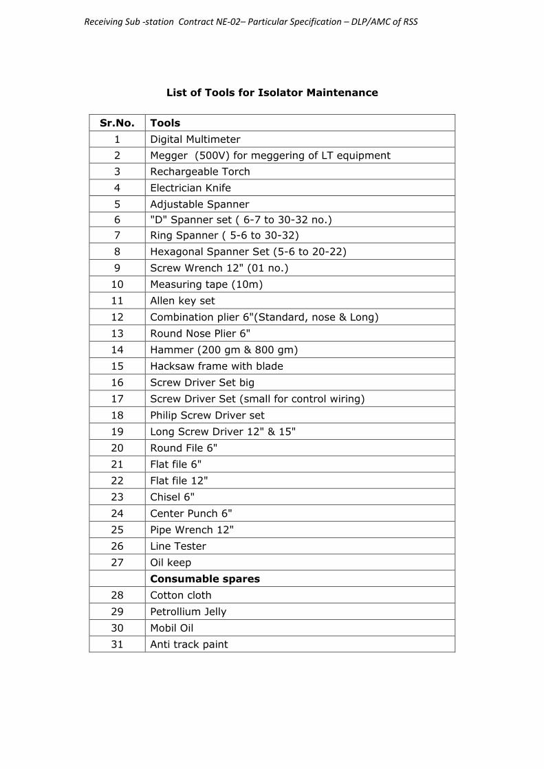
Receiving Sub -station Contract NE-02– Particular Specification – DLP/AMC of RSS
List of Tools for Isolator Maintenance
Sr.No. Tools
1 Digital Multimeter
2 Megger (500V) for meggering of LT equipment
3 Rechargeable Torch
4 Electrician Knife
5 Adjustable Spanner
6 "D" Spanner set ( 6-7 to 30-32 no.)
7 Ring Spanner ( 5-6 to 30-32)
8 Hexagonal Spanner Set (5-6 to 20-22)
9 Screw Wrench 12" (01 no.)
10 Measuring tape (10m)
11 Allen key set
12 Combination plier 6"(Standard, nose & Long)
13 Round Nose Plier 6"
14 Hammer (200 gm & 800 gm)
15 Hacksaw frame with blade
16 Screw Driver Set big
17 Screw Driver Set (small for control wiring)
18 Philip Screw Driver set
19 Long Screw Driver 12" & 15"
20 Round File 6"
21 Flat file 6"
22 Flat file 12"
23 Chisel 6"
24 Center Punch 6"
25 Pipe Wrench 12"
26 Line Tester
27 Oil keep
Consumable spares
28 Cotton cloth
29 Petrollium Jelly
30 Mobil Oil
31 Anti track paint
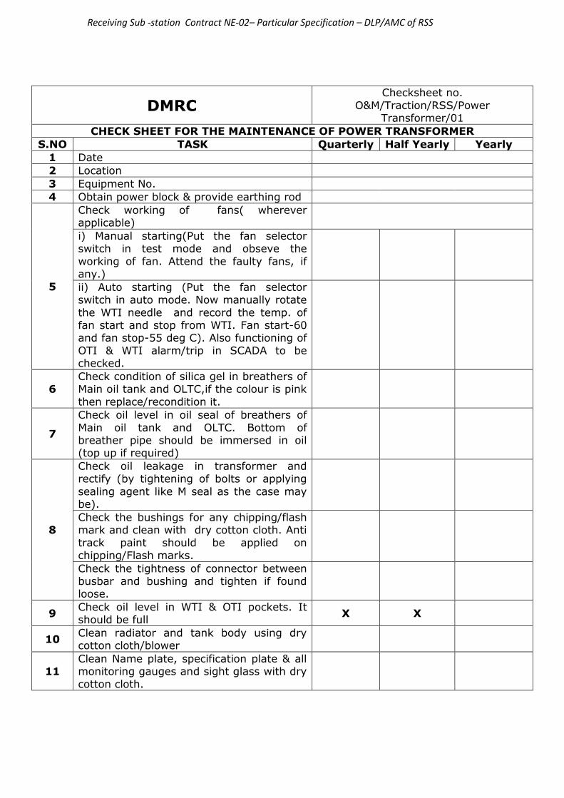
Receiving Sub -station Contract NE-02– Particular Specification – DLP/AMC of RSS
DMRC Checksheet no.
O&M/Traction/RSS/Power Transformer/01
CHECK SHEET FOR THE MAINTENANCE OF POWER TRANSFORMER
S.NO TASK Quarterly Half Yearly Yearly
1 Date
2 Location
3 Equipment No.
4 Obtain power block & provide earthing rod
5
Check working of fans( wherever applicable)
i) Manual starting(Put the fan selector switch in test mode and obseve the
working of fan. Attend the faulty fans, if any.)
ii) Auto starting (Put the fan selector switch in auto mode. Now manually rotate
the WTI needle and record the temp. of fan start and stop from WTI. Fan start-60 and fan stop-55 deg C). Also functioning of
OTI & WTI alarm/trip in SCADA to be checked.
6 Check condition of silica gel in breathers of Main oil tank and OLTC,if the colour is pink
then replace/recondition it.
7
Check oil level in oil seal of breathers of
Main oil tank and OLTC. Bottom of breather pipe should be immersed in oil (top up if required)
8
Check oil leakage in transformer and rectify (by tightening of bolts or applying
sealing agent like M seal as the case may be).
Check the bushings for any chipping/flash mark and clean with dry cotton cloth. Anti
track paint should be applied on chipping/Flash marks.
Check the tightness of connector between busbar and bushing and tighten if found loose.
9 Check oil level in WTI & OTI pockets. It should be full
X X
10 Clean radiator and tank body using dry cotton cloth/blower
11 Clean Name plate, specification plate & all monitoring gauges and sight glass with dry
cotton cloth.

Receiving Sub -station Contract NE-02– Particular Specification – DLP/AMC of RSS
12
Check operation of OLTC from RTCC, push button on OLTC panel and manually by
handle. Observe for any abnormality in operating mechanism during operation. Reset locking lever after manual operation
Verify the working of OTI & WTI indicators from RTCC panel and analog indicator of
Transformer. Record the Max temperature and reset the max temp indicator.
Change the tap position & Verify the change of tap position indicator at RTCC panel and
OLTC control box.
Lubricate all moving parts of OLTC with
general purpose grease & check all the connections for tightness
Measure BDV of OLTC and Main tank oil (Values should be >30kV for 66kV transformer,>40kV for 132 kV transformer
and >50kV for 220kV transformer), Filteration to be done if BDV is less than the
prescribed values.
X
13
Test oil parameters - DGA, PPM & acidity
(main tank) 0-4 yrs.. = Yearly, 4-10 Yrs = Half-yearly above 10 years = Quarterly
X
14
Measure winding IR value using 5kV megger. Value should be more than 200MΩ (for 25kV)
and 2000MΩ (for≥33kV). Measure IR at 60
sec & 10 sec and calculate PI Index(IR at 60 Sec/ IR at 10 Sec. It should be ≥ 1.4).
For meggaring of Auxillary transformer open ATCB, LBCB, neutral grounding isolator &
remove secondary PT fuse. For Traction transformer open TTCB, Transformer O/G CB & disconnect RC cable. Meggar to be
connected at bushing of transformer. OTI & WTI temperature reading also to be recorded
at the time of meggaring.
X
15
Check in SCADA for functioning of alarm/trip
of buchholz relay, Oil surge relay & Pressure release Valve by shorting the contacts as per wiring diagram.
16
Marshalling box ( Main tank & OLTC)
(i) Open the cover of Marshalling box remove the accumulated dust by vacuum cleaner. Check the condition of door closing & locking
mechanism.
(ii) Check condition of the gaskets of the
Marshalling box, replace if required
(iii) Check all the connections of control wiring for tightness.

Receiving Sub -station Contract NE-02– Particular Specification – DLP/AMC of RSS
(iv) Check for any discolouration/overheating sign on electrical connection.
(v) Check working of heater & Lamp.
17 Carry out Tan delta and capacitance measurement of bushing
X X
18 Carry out Tan delta measurement of windings
X X

Receiving Sub -station Contract NE-02– Particular Specification – DLP/AMC of RSS
List of Tools for Power Transformer maintenance
Sr.No. Tools
1 Transformer oil BDV kit
2 Megger 5kV
3 Digital Multimeter
4 Blower (Single phase 220V)
5 Vacuum cleaner (Single phase 220V)
6 Torque wrench
7 Rechargeable Torch
8 Electrician Knife
9 Adjustable Spanner
10 "D" Spanner set ( 6-7 to 30-32 no.)
11 Ring Spanner ( 5-6 to 30-32)
12 Hexagonal Spanner Set (5-6 to 20-22)
13 Screw Wrench 12" (01 no.)
14 Measuring tape (10m)
15 Combination plier 6"(Standard, nose & Long)
16 Round Nose Plier 6"
17 Hammer (200 gm & 800 gm)
18 Hacksaw frame with blade
19 Screw Driver Set big
20 Screw Driver Set (small for control wiring)
21 Philip Screw Driver set
22 Long Screw Driver 12" & 15"
23 Line Tester
Consumable spares
1 Cotton cloth
2 Insulating Tape (PVC)
3 HT Tape
4 Anti track paint
5 Silica Gel
6 M-seal

Receiving Sub -station Contract NE-02– Particular Specification – DLP/AMC of RSS
DMRC Check sheet no. O&M/Traction/RSS/CS/CB-25kV/01
CHECK SHEET FOR THE MAINTENANCE OF 25kV SF6 CIRCUIT BREAKER
S.No. TASK Quarterly Yearly
1 Date
2 Location
3 Equipment No.
Obtain power block & provide earthing rod
4
Open the cover of control box. Clean accumulated dust by vacuum cleaner. Also clean
the sight glass.
5
Check for moisture entry inside the box. Examine the door gasket and bellows of transmission rod
for any damage, replace if required
6 Check availability of handle, fixed inside the door panel, for manual operation
7
Check the operation manually as well as
electrically in local and remote mode, keeping the front door open, observe whether the mechanism
functions smoothly without any rubbing or obstruction.
8 Check working of semaphore indicator for open/close indication
9 Verify from SCADA status, the change of position of local/remote switch & open/close status.
10 Check the working of heater and lamp
11
Check electrical interlocking between CB and
associated isolators both locally & remotely. Isolators should not operate when CB is in closed condition.
12 Cut off DC and AC supply & discharging the spring by manual operation.
13 Check all electrical connections of control panel
for tightness.

Receiving Sub -station Contract NE-02– Particular Specification – DLP/AMC of RSS
14
Check the bushing insulator for any chipping and flash mark and clean with cotton cloth. Anti track
paint should be applied on chipping/Flash marks.
15 Check the working of counter and record the counter reading.
16
Check & record SF6 gas pressure from density monitor. If low indication is there check for any gas leakage by SF6 Leakage detector. Top up
gas, if required (Normal range : ABB-6.2-7 BAR)
17
Check functioning of SF6 Low pressure alarm in SCADA by shorting relevant contacts(as per
wiring diagram).
18 Check the transmission rod for any looseness.
Tighten, if required
19 Apply touch up paint in case of rusting found
inside or outside the control box.
20
Lubricate the moving parts. A very thin layer of Mobil 28 grease shall be rubbed on the sliding surface of the moving parts viz. Cam, Cam
wheel, Worm wheel, transmission roller, transmission cam and bearing.
21 Measure resistance of opening/closing coil by
multimeter (25 to 30 ohm). X
22
Check the IR value of the 110V DC motor with
500 volt meggar (min. value - 1 mega ohm). Clean the commutator with muslin cloth. Examine carbon brushes for any damage.
X
23
Check the condition of Bi-Metallic strip provided between connecting plate & bus bar connector for
any sulphation. Replace, if required.
X
24 Check the incoming & outgoing connections for tightness
25 Check the earth strip connections for tightness.
26 Check shock absorber for any movement & oil leakage.
27 Check nut & bolts of support structure for
tightness.

Receiving Sub -station Contract NE-02– Particular Specification – DLP/AMC of RSS
28 Check Remote Operation by TPC before cancellation of Power Block

Receiving Sub -station Contract NE-02– Particular Specification – DLP/AMC of RSS
List of Tools for 25 kV SF6 Breaker Maintenance
Sr.No. Tools
1 Digital Multimeter
2 Blower (Single phase 220V)
3 Vacuum cleaner (Single phase 220V)
4 Megger (500V) for meggering of LT equipment
5 SF6 Gas leakage detector
6 SF6 gas filling kit
7 Rechargeable Torch
8 Electrician Knife
9 Adjustable Spanner
10 "D" Spanner set ( 6-7 to 30-32 no.)
11 Ring Spanner ( 5-6 to 30-32)
12 Hexagonal Spanner Set (5-6 to 20-22)
13 Screw Wrench 12" (01 no.)
14 Measuring tape (10m)
15 Allen key set
16 Combination plier 6"(Standard, nose & Long)
17 Round Nose Plier 6"
18 Hammer (200 gm & 800 gm)
19 Hacksaw frame with blade
20 Screw Driver Set big
21 Screw Driver Set (small for control wiring)
22 Philip Screw Driver set
23 Long Screw Driver 12" & 15"
24 Round File 6"
25 Flat file 6"
26 Flat file 12"
27 Chisel 6"
28 Center Punch 6"
29 Pipe Wrench 12"
30 Line Tester
Consumable spares
31 Cotton cloth
32 Muslin cloth
33 Lubricating oil grade 20W40(make :- servo or castrol)
34 Insulating Tape (PVC)
35 Mobil 28 grease
36 Anti Track Paint
37 SF6 Gas
38 Enamel paint

Receiving Sub -station Contract NE-02– Particular Specification – DLP/AMC of RSS
DMRC Check sheet no. DMRC/O&M/Elect/CS/33kV GIS
CHECKSHEET FOR MAINTENANCE OF 33KV GIS
SNo. Task Half Yearly
1 Date
2 Location
3 Equipment No.
4 Check all the indicating lamps, meters, voltage indicators, relays
visually before shut-down.
5 Check the interlocking between LVCB, MVCB and Transformer door
through castle lock.
6
Check the breaker operation manually as well as electrically in local
and remote, observe whether the mechanism functions smoothly
without any rubbing or obstruction.
7 Check for the operation of the emergency trip mechanically and
electrically.
9 Check Semaphore indicator for indication of Open/Close
10 Check operation of Under Voltage relay of CB by switching off DC
supply (if applicable).
11 Check tripping of CB on over current by giving Test tripping
command.
12 Checking of three position switch operation & its indication in SCADA.
13 Check the spring charging time.
14 Check and note the pressure of SF6 in breaker chamber.
15 Remove accumulated dust in the panel by Vacuum cleaner
16 Check and note the pressure of SF6 in Bus chamber.
17 Check all cable glands for proper sealing.
18 Note the parameters in the relays i.e. current, voltage, log etc..
19 Check the hinges, gaskets & door lock.
20 Check the functioning of panel light and other accessories.
21 Check for the functioning of heater & thermostat.
22 Check the CT connections of CB for tightness. Also Record IR value
of CT.
23 Check Visually PT compartment for any abnormality & Check PT
fuse/MCB.
24 Check the earth strip connections for tightness.
25 Check the functioning of counter operation and record the counter
reading.
26 Check all fasteners of Control Panel body for tightness.
27 Visually inspect the panel body for rusting and paint, if required.
28 Check Remote Operation by TPC before cancellation of Power
Block.Check the working of spring cut off Limit switches.

Receiving Sub -station Contract NE-02– Particular Specification – DLP/AMC of RSS
DMRC Checksheet no. O&M/Traction/RSS/CS/Dry
type transformer/01
CHECKSHEET FOR MAINTENANCE OF 33 kV/415V Dry Type Aux. Transformer
S.NO TASK Half Yearly Yearly
1 Date
2 Location
3 Equipment No.
4
Note down the temperature of all
three phases. Also observe for any abnormal sound, before
power block.
5
Obtain power block. Check the
interlocking between LVCB, MVCB and transformer. Remove castle key from LVCB, insert it in MVCB
and Put it into test position. Close the earth switch of MVCB and put
the released key from earth switch into main door of enclosure of transformer for opening the
same.
6
Clean enclosure, transformer and
floor with vacuum cleaner. Blower not to be used for cleaning
7
Check nut/bolts of HV/LV termination for tightness. Also
check for sufficient clearance between delta cables/links. These
should not touch each other.
8
Visually inspect transformer,
HV/LV connections for overheating, flashmark and
discolouration of winding.
9
Manually Check the working of temperature monitoring unit by
lowering the setting of temperature, less than ambient temp and verify the alarm and
tripping of MVCB (Alarm=90ºC, Trip = 120ºC).

Receiving Sub -station Contract NE-02– Particular Specification – DLP/AMC of RSS
10
Clean all temperature sensors
with cotton cloth & tighten connections of control wiring in
temperature sensor junction box & Temperature monitoring unit.
11 Check the bolts of tap changer
links for tightness.
12 Check tightness of top & bottom insulated coil support.
13 Check earthing strips for tightness.
14
Check the surface of enclosure for
any rust. Treat with touch up paint, if required.
15
Manually Check the working of Cooling Fans, if available from
temperature monitoring unit by lowering the setting of temperature, less than ambient
temp.

Receiving Sub -station Contract NE-02– Particular Specification – DLP/AMC of RSS
List of Tools for 33 kV dry type transformer maintenance
Sr.No. Tools
1 Digital Multimeter
2 Vacuum cleaner (Single phase 220V)
3 Torque wrench
4 Rechargeable Torch
5 Electrician Knife
6 Adjustable Spanner
7 "D" Spanner set ( 6-7 to 30-32 no.)
8 Ring Spanner ( 5-6 to 30-32)
9 Hexagonal Spanner Set (5-6 to 20-22)
10 Screw Wrench 12" (01 no.)
11 Measuring tape (10m)
12 Combination plier 6"(Standard, nose & Long)
13 Round Nose Plier 6"
14 Hammer (200 gm & 800 gm)
15 Hacksaw frame with blade
16 Screw Driver Set big
17 Screw Driver Set (small for control wiring)
18 Philip Screw Driver set
19 Long Screw Driver 12" & 15"
20 Line Tester
Consumable spares
21 Cotton cloth
22 Insulating Tape (PVC)
23 HT Tape
24 Enamel Paint

Receiving Sub -station Contract NE-02– Particular Specification – DLP/AMC of RSS
DMRC Checksheet no. O&M/Traction/RSS/CS/Battery
bank/01
CHECKSHEET FOR THE MAINTENANCE OF Ni-Cd BATTERY BANK
S.NO TASK Quarterly Half Yearly Yearly
1 Date
2 Location
3 Equipment No.
4
Measure the battery bank voltage after switching off both the battery chargers. It should
be more then 110V
5 Before starting maintenance on battery, wear gloves and
goggles.
6
Clean the accumulated dust
using paint brush & dry cotton cloth over cell terminals, vent plug and cell body, starting
from top to bottom row of cells.
7
Check all battery inter cell links,
cable connector and earthing connection for tightness.
Replace with new/overhauled links if sulphation is found. Treat removed links with warm
water & nylon scrubber in workshop. Tighten inter cell
terminals with torque wrench (Torque for battery terminal- M10: 12 – 16 Nm
M20: 30 – 34 Nm)
X X
8
Check electrolyte level (It
should be between Max - Min marks. Top up with distilled
water, if required).
9 Check battery bank stand for
any rusting, paint if required.
10 Check each cell for leakage and bulging. If found, replace with new cell.
12
After one hour of switching off battery charger, measure and
record individual cell voltage. If voltage of any cell is less than

Receiving Sub -station Contract NE-02– Particular Specification – DLP/AMC of RSS
1.0 Volt, replace with new charged cell filled with sufficient
electrolyte.
13 Apply thin layer of petroleum jelly on battery terminals.
14
Perform capacity test of Battery
Bank. Discharge the battery bank at C5 rate i.e. 20% of
rated capacity. Cut off voltage to be set at 1V per cell (For ex. NiCad Battery bank of 340 AH
with 85 cells,C5 rating i.e at 68 Amp discharge rate, with
minimum permissible voltage of 85 volt-85 cells x 1 volt). It should give backup for 3 hrs. If
capacity is less i.e. voltage is falling below cut-off voltage
before 3 hrs, then find out defective cell by measuring individual voltage (Voltage ≥1 V)
and replaces the cell.
X X

Receiving Sub -station Contract NE-02– Particular Specification – DLP/AMC of RSS
DMRC Checksheet no.
O&M/Traction/RSS/CS/Battery charger/01
CHECKSHEET FOR MAINTENANCE OF BATTERY CHARGER
S.NO TASK Quarterly Half Yearly
1 Date
2 Location
3 Equipment No.
4 Observe the charger for any abnormal sound. Rectify the same if found.
5
Measure the output voltage of the battery chargers. (Float voltage = 119.0V and Boost
Voltage= 123.25V). Adjust the respective potentiometer, if any deviation is found.
6 Check working of automatic changeover of the
charger.
7
Check working of alarm, indications, switches (Input, Output, auto/manual, float/boost)
ammeter and voltmeter at charger as well as in SCADA.
8 Switch OFF the charger, Open the cover and clean accumulated dust with vacuum cleaner.
9 Check all cables (AC I/P & DC O/P) & earthing
connection for tightness.
10
Check the PCB Card and multi pin connector for
any damage/heating mark. Clean PCB cards with soft hair brush.
11 Check PCB cards and connections with IR camera for hot spots. X

Receiving Sub -station Contract NE-02– Particular Specification – DLP/AMC of RSS
List of Tools for Battery bank & Battery charger Maintenance
Sr.No. Tools
1 Digital Multimeter
2 Blower (Single phase 220V)
3 Vacuum cleaner (Single phase 220V)
4 Rechargeable Torch
5 Electrician Knife
6 "D" Spanner set ( 6-7 to 30-32 no.)
7 Ring Spanner ( 5-6 to 30-32)
8 Hexagonal Spanner Set (5-6 to 20-22)
9 Combination plier 6"(Standard, nose & Long)
10 Round Nose Plier 6"
11 Screw Driver Set (small for control wiring)
12 Philip Screw Driver set
13 Acid proof gloves
14 Goggles
15 Vent plug opener
16 Paint brush
17 Line Tester
18 Hydrometer
19 IR Camera
20 Nylon Scrubber
21 Soft hair brush
22 Discharge test kit
23 Torque Wrench
Consumable spares
24 Petroleum Jelly
25 Cotton cloth
26 Insulating Tape (PVC)
27 Distilled water
28 Battery Cell
29 Enamel Paint

Receiving Sub -station Contract NE-02– Particular Specification – DLP/AMC of RSS
DMRC Checksheet no.
O&M/Traction/RSS/CS/ACDB/01
Checksheet for ACDB Maintenance
S.No. TASK Yearly
1 Date
2 Location
3 Equipment No.
4
Check: 1. Status of earthing strip for tightness
2. Check for any sign of rust, apply touch up paint if required.
5 Check the status of door for smooth closing and
opening.
6 Check the condition of door gasket, replace if required.
7 Clean the exterior of ACDB box.
8
Clean the dust, cobweb and foreign materials inside
ACDB with the help of vacuum cleaner after switching off supply
9
Check the healthiness of following indication:
1. ON/OFF 2. LED Undervolatge relay
10 Check for any flashmark/overheating or other
abnormality of components

Receiving Sub -station Contract NE-02– Particular Specification – DLP/AMC of RSS
11 Check and tighten all electrical connections
12 Verify under voltage indication in SCADA from TPC by
shorting the contacts as per wiring diagram for ACDB.

Receiving Sub -station Contract NE-02– Particular Specification – DLP/AMC of RSS
DMRC Checksheet no.
O&M/Traction/RSS/CS/DCDB/01
Checksheet for DCDB Maintenance
S.NO TASK Yearly
1 Date
2 Location
3 Equipment No.
3
Check:
1. Status of earthing strip for tightness 2. Check for any sign of rust, apply touch up
paint if required.
4 Examine the status of door for closing and
opening
5 Examine the condition of door gasket, replace if required.
6 Clean the exterior of DCDB box.
7 Clean the dust, cobweb and foreign materials inside DCDB with the help of vacuum cleaner
8 Check the healthiness of following indication :
1. ON/OFF 2. LED Under volatge relay
9 Check for any flashmark/overheating or other abnormality of components
10 Check and tighten all electrical connections
11 Verify under voltage indication in SCADA from TPC by shorting the contacts as per wiring diagram
12
Check automatic changeover of Incomers-1&2
and coupler by switching incomers 1&2 off one by one. (Note-During changeover, Circuit breakers will trip)

Receiving Sub -station Contract NE-02– Particular Specification – DLP/AMC of RSS
13
Check changeover operation of Incomers-1&2
and coupler by push buttons. (Note-During changeover, Circuit breakers will trip)
14 Verify the change of status of on/off & Semaphore indicators during changeover in above mentioned steps

Receiving Sub -station Contract NE-02– Particular Specification – DLP/AMC of RSS
Tools and consumables for ACDB & DCDB Maintenance
Sl. No. Name
1 Multimeter
2 Vacuum cleaner
3 Cotton cloth
4 Tool kit
5 Paint and brush
6 Gasket

Receiving Sub -station Contract NE-02– Particular Specification – DLP/AMC of RSS
DMRC Checksheet no. O&M/Traction/RSS/CS/Fire system/01
CHECKSHEET FOR MAINTENANCE OF FIRE SYSTEM
S.NO TASK Daily Monthly Yearly
1 Date
2 Location
3 Equipment No.
4 Fire Alarm Control Panel (FACP) :
a Check the panel for normal operation. Any fault should be recorded and
urgently attended.
b Test LEDs of FACP panel by test push button for proper working
X
c Test atleast one smoke detector of each zone for initiation of alarm with smoke or aerosol. Detectors found defective should
be replaced.
X
d Test all smoke detector by aerosol and heat detectors by heat source such as
shielded heat lamp.
X X
5 Sand Bucket : One bucket stand having 6 Nos. bucket filled with sand
to be checked
X
6 Fire Extinguisher: (1) 3 Nos. 22.5 Kg Co2 cylinder with trolley near power transformer. (2) 4.5 kg Co2 type portable fire extinguisher kept in every room of RSS building
a Clean the exterior of fire extinguisher with cotton cloth.
X

Receiving Sub -station Contract NE-02– Particular Specification – DLP/AMC of RSS
b Check the nozzle outlet and vent holes as well as threaded portion of cap for
clogging, and check that plunger is moving freely. Ensure cap washer is
intact
X
c Record weight of CO2 cylinder by weighing the cylinder. If weight is 10%
less than the weight of the cylinder then it is to be sent for refilling. There should
be a sticker mentioning date of gas filling & refilling/testing due date and cylinder No.
X X
7 Weight Monitoring System: one No. 22.5 kg
cylinder and 2 Nos. 9kg cylinder.
a Alarm to be checked by lifting of
cylinder.
b Cylinder should be tested by weighing the cylinder. There should be a sticker mentioning
date of gas filling & refilling/testing due date and cylinder No.

Receiving Sub -station Contract NE-02– Particular Specification – DLP/AMC of RSS
DMRC Checksheet no.
O&M/Traction/RSS/CS/Thermography/01
CHECKSHEET FOR THERMOGRAPHY OF 220/132/66 kV RSS
S.NO TASK Half Yearly
1 Date
2 Location
3 Equipment No.
4 Check the temperature rise of cable termination,connecting jumper and clamps
5 Check the temperature rise of PT/CVT to bus connecting jumper and clamp.
6 Check the temperature rise of
incoming/outgoing connector of CT
7 Check the temperature rise of incoming/outgoing clamps of isolator
8
Check the temperature rise of
incoming/outgoing connector of Circuit Breaker.
9 Check the temperature rise of LA to bus
connecting clamp.
NOTE :- Temperature recorded should not be greater than 15 degree centigrade than
the ambient temperature, if found, same to be treated as hot spot and get it attended.
Thermography to be done in peak hours i.e. 09:00 – 11:00 and 17:00 – 19:00.

Receiving Sub -station Contract NE-02– Particular Specification – DLP/AMC of RSS
DMRC Checksheet no.
O&M/Traction/RSS/CS/Thermography/03
CHECKSHEET FOR THERMOGRAPHY OF TSS
S.NO TASK Half Yearly
1 Date
2 Location
3 Equipment No.
4 Check the temperature rise of cable
termination, connecting jumper and clamps
5
Check the temperature rise of
incoming/outgoing connector of Circuit Breaker.
6 Check the temperature rise of incoming/outgoing connector of CT
7 Check the temperature rise of
incoming/outgoing clamps of isolator
8 Check the temperature rise of PT to bus
connecting jumper and clamp.
9 Check the temperature rise of LA to bus
connecting clamp.
10 Check the temperature rise of outgoing cable termination, connecting jumper and clamps
NOTE :- Temperature recorded should not be greater than 15 degree centigrade than the ambient temperature, if found, same to be treated as hot spot and get it attended.
Thermography to be done in peak hours i.e. 09:00 – 11:00 and 17:00 – 19:00.

Receiving Sub -station Contract NE-02– Particular Specification – DLP/AMC of RSS
DMRC Checksheet no.
O&M/Traction/RSS/CS/Thermography/02
CHECKSHEET FOR THERMOGRAPHY OF POWER TRANSFORMER
S.NO TASK Half Yearly
1 Date
2 Location
3 Equipment No.
4 Check the temperature rise of HT bushing
terminal and clamp.
5 Check the temperature rise of LT bushing terminal and clamp.
NOTE :- Temperature recorded should not be greater than 15 degree centigrade
than the ambient temperature, if found, same to be treated as hot spot and get it attended.
Thermography to be done in peak hours i.e. 09:00 – 11:00 and 17:00 – 19:00.

Receiving Sub -station Contract NE-02– Particular Specification – DLP/AMC of RSS
DMRC Checksheet no.
O&M/Traction/RSS/CS/AC/01
CHECHKSHEET FOR MAINTENANCE OF Air Conditioners
S.No. TASK Half Monthly Monthly
1 Date
2 Location
3 Equipment No.
4 Clean the filter of indoor unit. Replace, if
found damaged.
5 Dry clean condenser of outdoor unit by using blower.
6 Clean evaporator coil by using soft
brush.
7
Check grill temperature of evaporator
coil, it should be less than 10 deg. centigrade.
8 Check the working of condenser motor in outdoor unit and evaporator fan
motor in indoor unit
9
Check input current of all motors (blower, compressor and condenser) it
should not be more than 10% of rated current.
X

Receiving Sub -station Contract NE-02– Particular Specification – DLP/AMC of RSS
List of Tools for A.C Maintenance
Sr.No. Tools
1 Digital Multimeter
2 Clamp meter
3 Thermometer.
4 Blower,230V AC
5 Screw Driver Set
6 Soft brush
7 Line Tester
Consumable spares
1 Cotton cloth

Receiving Sub -station Contract NE-02– Particular Specification – DLP/AMC of RSS
Annexure No. 1
Recommended torque for bolts
Screw
Electrical connections (Nm) Mechanical connections
(Nm) Iron Brass
M6 15-20 10-15 35
M8 40-50 15-20 60
M10 60-70 30-40 85
M12 70-80 50-60 95
M14 100-120 70-80 150
M16 130-140 90-100 230
M18 - - 320
M20 - - 450
M22 - - 600
M24 - - 750
Head of the bolt should be matched with Socket of the torque set

Receiving Sub -station Contract NE-02– Particular Specification – DLP/AMC of RSS
LOG SHEET for RSS Readings
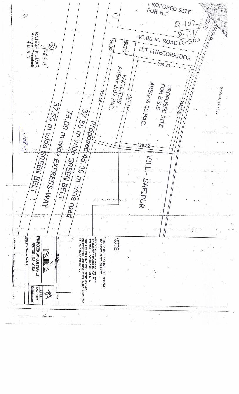


Contract Package NE-02: Pricing Document
Vol-7/ BOQ Page 8R of 47
Section summaries Corridor S1 -- Sector-83 Noida RSS
Statement B11
Cost
Centers Description of Cost Centers Amount in Foreign Currency
Amount in Indian Rupees
A Detailed Design
B Manufacture and Delivery
C Installation, Site Testing and Energisation
D Civil work
E System Acceptance Tests, Integrated Testing
and Commissioning
TOTAL CARRIED TO TENDER TOTAL
SECTION B12– OPTIONAL ITEMS (To be evaluated in financial Bid)
Unit Prices for optional items Amount in Foreign Currency
Amount in Indian Rupees
1(i)
AMC of sector-83 Noida RSS AMC cost for Ist year after DLP of sector-83 Noida RSS
1(ii) AMC cost for 2nd year after DLP of sector-83 Noida RSS
1(iii) AMC cost for 3rd year after DLP of sector-83 Noida RSS
TOTAL CARRIED TO TENDER TOTAL
GRAND TOTAL OF CORRIDOR S1 (B11+B12)

Contract Package NE-02: Pricing Document
Vol-7/ BOQ Page 9R of 47
Section summary Corridor S2 -- Sector-153 Noida RSS
Statement B21
Cost Centers Description of Cost Centers Amount in
Foreign Currency Amount in
Indian Rupees A Detailed Design
B Manufacture and Delivery
C Installation, Site Testing and Energisation
D Civil work
E System Acceptance Tests, Integrated Testing
and Commissioning
TOTAL CARRIED TO TENDER TOTAL
SECTION B22– OPTIONAL ITEMS(To be evaluated in financial Bid)
Unit Prices for optional items Amount in Foreign Currency
Amount in Indian Rupees
1(i)
AMC of sector-153 Noida RSS AMC cost for Ist year after DLP of sector-153 Noida RSS
1(ii) AMC cost for 2nd year after DLP of sector-153 Noida RSS
1(iii) AMC cost for 3rd year after DLP of sector-153 Noida RSS
TOTAL CARRIED TO TENDER TOTAL
GRAND TOTAL OF CORRIDOR S2 (B21+B22)

Contract Package NE-02: Pricing Document
Page 12R of 47
Statement C - BRIEF DESCRIPTION OF key dates for SECTIONS
RSS Tentative Date for Award of
LOA
Start of civil work
Start of submission of
vendor proposal for equipment drawing etc for
approval
Completion of delivery of
major materials at site like
Transformers,GIS bays,
Incoming Cables and
control panels
Completion of Erection of RSS
equipment, EHV cabling and all civil engineering
works
Testing, commissioning and charging of
both RSS including EHV
cabling
Integrated testing ,and Commissioning and Handing over
KD 1 KD 2 KD 3 KD 4 KD 5 KD 6
S1 - Sector-83 Noida
30.09.15 31.03.16 26 weeks
30.05.16 35 weeks
31.01.17 70 weeks 30.04.17 83 weeks 30.06.17 91 weeks 30.09.2017 104 weeks
S2 - Sector-153 Noida
30.09.15 31.10.15 4 weeks 31.12.15 13 weeks 31.07.16 44 weeks 31.10.16 57 weeks 30.11.16 61 weeks 30.06.2017 91 weeks
1. These dates are sacrosanct and are to be strictly adhered to. The tenderer may fill the other milestone dates accordingly. The
site will be available immediately after issue of LOA. 2. If the date of LOA varies due to some unforeseen reasons, other dates as mentioned above will advance/get
postponed accordingly. However, the ROD date is Firm. ROD is 01.12.17. 3. KM: 0 – Noida Sec-71
KM: 30 – Greater Noida Depot 4 If any of the above date is a holiday, then the first next working day shall be the key date.
K M:0 – Noida Sec-71 KM: 30- Greater Noida Depot

Contract Package NE-02: Pricing Document
Vol-7/BOQ Page 39R of47
Table A (Spare Part List)
Item No. WORK DESCRIPTION Unit Qty
Unit Price Total Price
INR FC. INR FC.
1 132 kV Bushing nos. 1
2
Set of tank gaskets and joints for 132kV / 33kV 30/45 10/15 MVA, 3 phase transformer nos. 1
3 Set of tank gaskets and joints for 132kV / 25kV Traction transformer nos. 1
4 SAS Cubicle, each containing the BCU and BPU equipments, complete
- for Incomer bay nos. 1
- for outgoing transformer bay nos. 2
- for Bus Coupler bay nos. 1
5 Workstation (RAID 5 Server) nos. 2
6 Printer (on the fly type, A4) nos. 1
7 Printer (Laser type, monochrome, A4 & A3) nos. 1

Contract Package NE-02: Pricing Document
Vol-7/BOQ Page 44R of47
Item No. WORK DESCRIPTION Unit Qty
Unit Price Total Price
INR FC. INR FC.
27 Thermal Imaging Camera with color LCD display, range upto 250 ° C, with expandable memory and PC interface.
nos. 1
28 Digital Earth Resistance meter nos. 2
29 Time interval meter suitable to measure closing/opening time of CB nos. 2
30 Contact resistance meter nos. 2
31
Handy kit for substation having high accuracy digital multimeter, contunuity tester, wire stripper & cutter, Banana clips for shorting CT secondary, soldering iron etc
nos. 2
32 CT/PT accuracy tester nos. 1
33
High voltage detector portable type suitable upto 33 kV installations and able to sense presence of HT from a distance to sense presence of HT from a distance of approx. 2 meter.
nos. 2
34 Resonance circuit High Voltage test kit nos. 1
35 Adapter for cable testing as per clause 2.1.1.1.20 of Ch-8A, vol-4 nos 1

Contract Package NE-02: Pricing Document
Vol-7/BOQ Page 47A of47
Checklist Sl. No. Description Remarks Page No
A. GENERAL 1 Contract No. 2 Name of Contract 3 Name & Address of the Contractor
4 Total Value of Contract 5 Details of the works / equipment for which
the Vendor / Sub-Contractor is proposed
6 Name of the proposed Vendor / Sub-Contractor
7 Address of the proposed Vendor / Sub-Contractor
8 Name , Designation and details of the Contact Person of the Vendor / Sub-Contractor
9 Total Value of work proposed to be done by Vendor / Sub-Contractor
B. COMPANY PROFILE & EXPERIENCE OF VENDOR
1 Type of proposed Vendor / Sub-Contractor (Proprietor , Partnership , Pvt. Ltd. or Limited Company
2 Date of Incorporation of the Company 3 Experience of the proposed Vendor /
Sub-Contractor for the proposed scope of work
4 Address of Manufacturing Facilities for the item
5 Annual Manufacturing capacity for proposed item.
6 Organizational details of the Vendor / Sub-Contractor
7 Manpower Strength of the Company 8 Are 'in-house' Design, Testing and R&D
facilities available? (If 'Yes' , please provide details)
C. CLAUSE BY CLAUSE COMPLIANCE OF THE RELEVANT CLAUSE OF SPECIFICATIONS (GS & PS) SUBMITTED

Contract Package NE-02: Pricing Document
Vol-7/BOQ Page 47B of47
1 Is there any deviation from the contract conditions / specifications. We hereby confirm that all implicit and
explicit deviations, comments and
remarks mentioned elsewhere in our
proposal shall be treated as NULL and
VOID and stand withdrawn. We hereby
confirm that but for the deviations noted in
this Appendix-A our offer is fully and truly
compliant.
2 Reasons for the deviation (if any) 3 Is there any price adjustment for the
deviation?
D. DETAILS OF WORK EXPERIENCE IN PROVIDING SIMILAR PRODUCT / SERVICES IN LAST 10 YEARS
(Enclose copy of the Work Completion Certificates / Product Performance Certificate from the client indicating the scope of work, make & model of the component , quantity , total value , year of completion , installation and the remark on performance). Certificate must be on the letter head of the client and must contain the contact details of the client's representative for verification.
a Summary of Certificate – 1 b Summary of Certificate – 2 c Summary of Certificate – 3 d Summary of Certificate – 4 e Summary of Certificate – 5 Has the Vendor / Sub-Contractor been
blacklisted by any Public Sector Undertaking , State Govt. / Central Govt. Department or Agency in India or Abroad
a If 'Yes' , please provide the details 2 Has the proposed component / material
been used in Delhi Metro Rail Corporation. (If 'Yes', please provide the details thereof, accompanied by the experience certificate from DMRC.)
3 Has the proposed component / material been used in any other Metro System worldwide. (If 'Yes', please provide the details thereof , accompanied by the client certificate.)

Contract Package NE-02: Pricing Document
Vol-7/BOQ Page 47C of47
E. DETAILS OF THE FACILITIES AVAILABLE AT WORKS / MANUFACTURING UNIT WHERE THE PROPOSED EQUIPMENT / PRODUCT SHALL BE MANUFACTURED
F. QUALITY CERTIFICATE 1 Independent Certification / Accreditation
available for the manufacturing unit (e.g. ISO 9001, etc.)
a Number & Date of Issuance of Certificate b Certificate issued by c Validity of the Certificate d Scope for which certification has been
issued
2 Details of In-House Testing Facilities a The Test Facility is as per which Indian or
International Standard
b Is this as per the Standard prescribed in Contract
c Is the Facility accredited by an independent agency
d Name of LAB with which In-House Facility accredited
G. FINANCIAL DATA 1 Audited Financial Statement for last 3
years submitted
2 Net worth of the Vendor / Sub-Contractor 3 Is Net worth of Vendor / Sub-Contractor
adequate (i.e., > Total Value of Proposed Work / 1.5 years)
4 Profitability (should be positive in last 3 years)
5 Liquidity of the Vendor / Sub-Contractor 6 Is Liquidity of Vendor / Sub-Contractor
adequate? (Liquidity must be adequate to meet the cash-flow required for minimum 3 months or the main contractor to submit the Undertaking / Guarantee to ensure adequate cash-flow)

Contract Package NE-02: Pricing Document
Vol-7/BOQ Page 47D of47
H. TYPE TEST CERTIFICATES (Type Test certificates from laboratories
for the proposed type of equipment /to establish the technical capability of the Vendor) (Incase, specific requirements are mentioned in the relevant specifications with regard to Type Testing, same shall also be complied additionally).
1 Is the Type Test Certificates provided? 2 Validity Date of Test Certificate? 3 Is the Test Report from an reputed
laboratory? (If ‘Yes’, please attach details of the same).
4 Test Report is accompanied by the Calibration Reports of test-set-up / instruments used , etc.
5 Is the certificate/report for the proposed model?
6 Is the Test Certificate as per the standard stipulated in the contract?
7 Is the Test Certificate not more than 5 or 10 years old? (as applicable in the contract)
I. TIME PERIOD FOR DELIVERY OF MATERIAL OR FOR EXECUTION OF THE PROPOSED WORK
a Work Program / Delivery Schedule submitted
b What are the critical activities? c Does the proposed delivery schedule /
work program meets the Contract Requirement?
J. AFTER SALES SERVICE
1 List of recommended Spares and life is enclosed
2 Details of After Sales Support system in Delhi
a List of authorized dealers of Spares is enclosed
b Price list of Spares is enclosed? c Vendor's Undertaking confirming that
Spares will be available during the lifetime of the product , irrespective of up gradation / phasing-out of the component / item is enclosed.
d Back-to-back agreement between main contractor and Vendor for providing full support during Defect Liability Period. (Copy of the formal agreement may be submitted after approval of Vendor).

Contract Package NE-02: Pricing Document
Vol-7/BOQ Page 47E of47
E Is confirmation of contractor and vendor complying to the requirements of SCC clause 60 enclosed.
K. TOOLS & TACKLES
(applicable only for subcontractor proposal)
a Details of Tools & Tackles available with the proposed Sub-Contractor for this work
b Copy of valid Calibration Certificates is submitted
c Copy of Test Certificates , Fitness Certificates , etc.
L. MANPOWER
(applicable only for sub-contractor proposal)
a Details of Manpower proposed b Is manpower proposed has relevant
experience of work execution?
c Has the Firms proposed any Safety organization? Please provide the details
M. ANY OTHER DETAILS RELEVANT TO THE PROPOSAL
a Weather Handling, Storage, protection and installation guidelines issued by OEM are furnished. We confirm to comply with the same.
b Whether copies of relevant IS/IEC Enclosed
c Service life certificate from OEM attached.
d Factory acceptance test plan We confirm that the applicable tests as per contract and relevant standards are included in the same.
e Quality assurance plan
CONFIRMATIONS :-
A The proposal is in accordance with the contract agreement.
B The equipment proposed is proven one and has been in service for last __ years.
C The proposed equipment will be compatible with the main equipment / machinery.
D The proposed equipment performance will not affected by EMI / EMC effects of 25 kV single phase OHE. (Report of EMI / EMC study is enclosed, if applicable).
E The capability of the Vendor / Sub-Contractor has been duly verified by us, as per the contract requirements and we confirm that the Vendor / Sub-Contractor will meet all the contractual requirements.

Contract Package NE-02: Pricing Document
Vol-7/BOQ Page 47F of47
F Sub-Contractor will ensure payment of minimum wages and proper Workmen Compensation Policy & Insurance Policy and compliance of other statutory provisions
G Sub-contractor will ensure compliance to all applicable tax laws.
H Sub-Contractor's / vendor's warranty and other documents as required by employer's requirements and contract conditions shall be submitted by us on approval of the proposed Sub-Contractor / Vendor.
I We hereby confirm that on approval copy of the agreement between the main contractor and Vendor / Sub-Contractor will be submitted to DMRC for ensuring after sales support during DLP / AMC and for support for supply of spare parts for 10 years beyond the DLP.
J We confirm that Electrical Sub-Contractor (if applicable) shall be allowed to execute the work only if they possess Electrical License and a copy of the same will be submitted to DMRC , prior to commencement of work at site.
K We undertake to propose suitable alternative if DMRC does not find the proposed Vendor / Sub-Contractor capable or the proposed Vendor / Sub-Contractor fails to comply with the delivery schedule at NO extra cost to DMRC.
L Manufacturer has given the details of orders in hand vis a vis spare production capacity and the same are enclosed herewith. We confirm that the Vendor is capable of complying with the delivery schedule so as to meet the key dates of the Contract.
M The vendors engineer shall be involved during the installation, testing, commissioning of the equipment at site and certify that these activities has been carried out as per the manufacture’s recommendations.
All the statements, information and answers given above are true and no information has been suppressed. In
case of any information being found incorrect or misleading, DMRC will be at liberty to take suitable action as considered appropriate.
( )
Date : Place :
Name & Signature of the Authorized Signatory of the Main Contractor with Company Seal

NAME OF THE FIRM
S.No Description Amount in Foreign Currency Amount in Indian Rupees
1 Grand Total of Cost Centers for RSS at Sector - 83 (s1) 0.00 0.00
2 Grand Total of Cost Centers for RSS at Sector - 153 (S2) 0.00 0.00
3 Grand Total of Cost Centers for Misclleneous Items (S1 & S2) 0.00 0.00
4 GRAND TENDER TOTAL 0.00 0.00
Rebate If any (In percentage) (FOREIGN CURRENCY) 0.00 0.00
Rebate If any (In percentage) (INDIAN RUPEES)
Net Amount after Rebate 0.00 0.00
0

Item Condition, Qualification, Deviation, etcKey date affected by each condition,
qualification, deviation, etc. Foreign Currency Indian Rupees
Increase or Decrease for unqualified withdrawal of each conditions, qualification, deviation etc
CONTRACT NE-02
Instructions to Tenderers Annexure 4
(To be submitted with financial bid)
Appendix C - Pricing of Unqualified Withdrawal of Conditions, Qualifications, Deviations, etc
NAME OF WORK: Design, Detail Engineering, Supply, Installation, Testing andCommissioning, 132 kV receiving cum 25 kV AC Traction cum 33 kV Auxiliary Main
Sub Stations and EHV cabling for Noida-Greater Noida Corridors of Delhi Mass RapidTransport System Project Phase-3
NAME OF THE FIRM 0


Note:
4. All deviations have been listed and priced in the financial proposal and deviations not priced will be treated as null and void and stand withdrawn at nil price
Total
In connecting this appendix, the Tenderer shall show every key date that will be affected by each condition, qualification, deviation, etc., included in his Financial Package for the unqualified withdrawal of that condition, qualification, deviation, etc.
1. We hereby confirm that the pricing for unconditional withdrawal of the above deviations has been given in the financial bid.
2.We hereby confirm that all implicit and explicit deviations, comments and remarks mentioned elsewhere in our proposal shall be treated as NULL and VOID and stand withdrawn.
3. We hereby confirm that but for the deviations noted in this Appendix our offer is fully and truly compliant.

Contract Package NE-02: Pricing Document
Vol-7/ BOQ Page 1R of 47
Design, Detail Engineering, Manufacture, Supply, Installation, Testing and Commissioning of 132KV receiving Cum-25 kV AC Traction Cum- 33 kV Auxiliary Main Sub Stations and EHV cabling for Noida-Greater Noida Corridors of Delhi Mass Rapid Transport System Project Phase-3
CONTRACT PACKAGE – NE-02
Pricing Document
Description Page Instructions for Completing the Pricing Document 2
Clause A Apportionment of Fixed Lump Sum Price to Cost Centers & Milestones 2 B Milestones Achievement Periods 2 C Milestone Payment Schedule (MPS) 2 D Tender Total 3 E Currency 3 F Milestones 4 G Price Variation 4 H Vendor Approval Policy 4
Statement A Tender Total 6
Statement B Section Summaries 8
Statement C Brief Description of Sections 12
Statement D Corridor Cost Centers 14
Statement E Miscellaneous Cost Centers 33
Statement F Unit Prices 40
Statement G Monthly Cash Flows 42

Contract Package NE-02: Pricing Document
Vol-7/ BOQ Page 2R of 47
INSTRUCTIONS FOR COMPLETING THE PRICING DOCUMENT General Requirements This Part of the Contract is a fixed Lump Sum Price Contract for “Design, Detail Engineering, Manufacture, Supply, Installation, Testing and Commissioning of 132KV receiving Cum-25 kV AC Traction Cum- 33 kV Auxiliary Main Sub Stations and EHV cabling and SCADA Systems for Noida-Greater Noida Corridors of Delhi Mass Rapid Transport System Project Phase-3
Tenderer is requested to refer clause 24 of SCC while quoting the rates.
A. Apportionment of Fixed Lump Sum Price to Sections and to Cost Centers and Milestones under each Section
1 The whole of Works including design is divided into Sections, primarily on geographical basis. Each Section is divided into the various Cost Centers named according to their general scope of work.
2 The fixed Lump Sum price for the whole of Works shall be apportioned by the Tenderer amongst the various sections. The apportioned amount for each Section will be further distributed among various Cost Centers included in that Section, separately for foreign currency and for the Rupee portion. The apportioned amount for each Cost Centre will be further distributed amongst various Milestones included in that Cost Centre, separately for the Foreign Currency and the Rupee Portion.
3 The sum of amounts shown against Milestones in a Cost Centre is the Cost Centre total that is to be carried forward to the Section Summary. The division of the respective Cost Centre totals between Indian Currency and Foreign currency shall be shown in the said Summary. The Section Summary will be carried forward to the Tender Total.
4 The scope and extent of the Works are to be ascertained by reference to the Contract Documents as a whole and shall not be limited in any manner whatsoever by the descriptions of the Cost Centers under each Section or of the Milestones under each Cost Centre, as given in the Appendices to the Pricing document.
5 Not used.
B. Milestones Achievement Periods
1. The Milestones under each Cost Centre shall identify verifiable steps towards the completion of the work within that Cost Centre under a Section. The Tenderer shall indicate the periods (in weeks from the Commencement Date of the Works) within which he shall achieve each Milestone.
C. Milestone Payment Schedule (MPS)
1. The MPS completed by the Contractor shall set out the maximum cumulative amount for all Cost Centers for all Sections put together in relation to each month for which payment may be sought in accordance with Sub-Clause 11.4 of the GCC. This information should also be presented in a tabular form. Monthly Cash Flows for the Contract will form part of the Pricing Document. The Milestone dates to be filled by the contractor shall match the key dates for Sections given in statement C below.
2. The MPS covers the period which will commence on the first day of the calendar month

Contract Package NE-02: Pricing Document
Vol-7/ BOQ Page 3R of 47
next after the month containing the Commencement Date of the Works as per the Contract. The first application for interim payment may be made not earlier than during the month following the calendar month next after the month containing the Commencement Date of the Works, such first application relating to the first month (i.e. month 1) of the MPS.
3. The price shall not be unbalanced therefore, the price quoted for S1 & S2 in the Cost Center-C (Installation and Site Testing) and Cost Center-E (System Acceptance Tests, Integrated Testing and Commissioning) shall not be less than 15% and 10% of the price quoted in the Cost Center-B (Manufacture and Delivery).
4. The payment in S1 & S2 for cost Center-B (Manufacture and Delivery) shall be given 75% on delivery subjected to submission of following documents in support of dispatch of material, 15% after completion of cost center C and remaining 10% as after completion of milestone mention under cost center-E (System acceptance, test, Integrated testing and Commissioning)
i) Certificate of Type test,
ii) Provision of Indemnity bonds as per clause no.46 of SCC.
iii) Certificate of factory acceptance test
iv) Proof of Insurance
v) Technical literature, installation manual and Equipment manuals
vi) Packing list
5. The payment for Section Miscellaneous will be paid in 100% as the milestone is achieved. The payment of AMC shall be done as per relevant clause of PS.
D. Tender Total
1. The Tender Total submitted by the Tenderer shall be in the format shown in the Pricing Document. It may be noted that the item against which no rate or sum is entered by the tenderer whether the quantity is entered or not shall be regarded as covered by other rates in the statement of price.
2. The Pricing Document contains Sections, Cost Centers under each Section, and Milestones under each Cost Centre. The Sections, Cost Centers and Milestones have been prepared to indicate the extent of detail required in the Tender. The Tenderer shall prepare and complete documents, in this format, as being his Tender and submit as part of the Financial Package.
3. The Pricing Document completed and submitted by the Tenderer, as part of his Tender, should use an indexing and page numbering system such that its extent and completeness is clearly evident. The rates shall be quoted in excel file provided in bid documents. The tenderer shall download the excel file and after quoting their rates upload the same accordingly. The rates shall not be offered/quoted elsewhere in the technical submission/ tender submission.
E. Currency
1. Section Totals, Cost Centre Totals and Milestone amounts shall be indicated in Indian Rupees and in a foreign currency, wherever required.

Contract Package NE-02: Pricing Document
Vol-7/ BOQ Page 4R of 47
F. Milestones
1. Cost Centers under each Section are fixed and shall not be changed by the Tenderer. The Tenderer, however, may add additional Milestones in a Cost Centre provided such Milestones genuinely related to that Cost Centre activity. The Cost Centers represent the major items of the Works for which the Employer will pay the Contractor, and the Tenderer shall ensure that he has allowed for all his costs he requires for the Contract to meet the Employer’s Requirements.
2. If during the course of execution, it becomes necessary, to meet the Employer’s Requirements (as indicated in these Tender Documents), to add more Milestones in a Cost Centre, the Lump Sum Price of the whole of Works, which will remain unaltered, will be reapportioned amongst the Sections, and further redistributed under the Cost Centers in each Sections and the Milestones in each Cost Centre. The liability of the Employer will be limited to the fixed Lump sum Price already accepted and the Contractor will have no right to claim any thing over and above the fixed Lump Sum price for any such addition of Milestones in any Cost Centre. The decision of the Employer will be final and binding in such matters and will not be subject to Conciliation or Arbitration.
3. The Milestones represent the completion of verifiable activities to be undertaken by the Contractor. A date for the achievement of each Milestone expressed as a number of weeks from the Commencement Date of the Works shall be entered in the column provided. Milestones that lead to achievement of a Stage must always precede the Key Date for achievement of that Stage. Milestones shall be converted to Calendar dates when the Notice to Proceed is issued.
G. Price Variation:-
Prices quoted by the tenderer shall be fixed throughout the Tenderer’s performance of the contract and not subject to variation on any account except Traction and Auxiliary Transformers.
The variation in Traction and Auxiliary Transformers prices will be governed by IEEMA formula. Copy of the relevant formula is enclosed as Annexure B. Latest date of delivery for considering price variation shall not be later than 180 days before the relevant Key Date for commissioning of RSS (Extended key date if extension of time is permitted by the employer). If transformer is delayed by 180 days, then the variation shall be paid as on above benchmark of 180 days or on as actual date whichever is less.
H Vendor Approval Policy : Attached as Annexure-A

Contract Package NE-02: Pricing Document
Vol-7/ BOQ Page 5R of 47
Design, Detail Engineering, Manufacture, Supply, Installation, Testing and Commissioning 132KV receiving Cum-25 kV AC Traction Cum- 33 kV Auxiliary Main Sub Stations and EHV cabling for Noida-Greater Noida Corridors of Delhi Mass Rapid Transport System Project Phase-3
CONTRACT PACKAGE – NE-02
Statement A
Tender Total

Contract Package NE-02: Pricing Document
Vol-7/ BOQ Page 6R of 47
Statement A – TENDER TOTAL
(THIS DOCUMENT IS TO BE PREPARED AND COMPLETED BY THE TENDERER) GRAND TOTAL OF Corridor S1 -- Sector-83 Noida RSS Rupees _____________________________________________________ (In figures)
______________________________________________________ (In words)
And
(In Foreign Currencies) _________________________________________ (In figures)
_________________________________________ (In words)
GRAND TOTAL OF Corridor S2- Sector-153 Noida RSS
Rupees _____________________________________________________ (In figures) ______________________________________________________ (In words)
And
(In Foreign Currencies) _________________________________________ (In figures)
___________________________________________( in words) GRAND TOTAL OF Section Miscellaneous
Rupees _____________________________________________________ (In figures)
______________________________________________________ (In words)
And
(In Foreign Currencies) _________________________________________ (In figures)
_________________________________________ (In words)
The Total Fixed Lump Sum Price of this Contract (Sum of all above three section) :-
Rupees _____________________________________________________ (In figures)
______________________________________________________ (In words) And
(in Foreign Currencies)___________________________________________(in figures) ___________________________________________( In words)

Contract Package NE-02: Pricing Document
Vol-7/ BOQ Page 7R of 47
Design, Detail Engineering, Manufacture, Supply, Installation, Testing and Commissioning 132KV receiving Cum-25 kV AC Traction Cum- 33 kV Auxiliary Main Sub Stations and EHV cabling for Noida-Greater Noida Corridors of Delhi Mass Rapid Transport System Project Phase-3
CONTRACT PACKAGE – NE-02
Statement B
Section Summaries

Contract Package NE-02: Pricing Document
Vol-7/ BOQ Page 8R of 47
Section summaries Corridor S1 -- Sector-83 Noida RSS
Statement B11
Cost
Centers Description of Cost Centers Amount in Foreign Currency
Amount in Indian Rupees
A Detailed Design
B Manufacture and Delivery
C Installation, Site Testing and Energisation
D Civil work
E System Acceptance Tests, Integrated Testing
and Commissioning
TOTAL CARRIED TO TENDER TOTAL
SECTION B12– OPTIONAL ITEMS (To be evaluated in financial Bid)
Unit Prices for optional items Amount in Foreign Currency
Amount in Indian Rupees
1(i)
AMC of sector-83 Noida RSS AMC cost for Ist year after DLP of sector-83 Noida RSS
1(ii) AMC cost for 2nd year after DLP of sector-83 Noida RSS
1(iii) AMC cost for 3rd year after DLP of sector-83 Noida RSS
TOTAL CARRIED TO TENDER TOTAL
GRAND TOTAL OF CORRIDOR S1 (B11+B12)

Contract Package NE-02: Pricing Document
Vol-7/ BOQ Page 9R of 47
Section summary Corridor S2 -- Sector-153 Noida RSS
Statement B21
Cost Centers Description of Cost Centers Amount in
Foreign Currency Amount in
Indian Rupees A Detailed Design
B Manufacture and Delivery
C Installation, Site Testing and Energisation
D Civil work
E System Acceptance Tests, Integrated Testing
and Commissioning
TOTAL CARRIED TO TENDER TOTAL
SECTION B22– OPTIONAL ITEMS(To be evaluated in financial Bid)
Unit Prices for optional items Amount in Foreign Currency
Amount in Indian Rupees
1(i)
AMC of sector-153 Noida RSS AMC cost for Ist year after DLP of sector-153 Noida RSS
1(ii) AMC cost for 2nd year after DLP of sector-153 Noida RSS
1(iii) AMC cost for 3rd year after DLP of sector-153 Noida RSS
TOTAL CARRIED TO TENDER TOTAL
GRAND TOTAL OF CORRIDOR S2 (B21+B22)

Contract Package NE-02: Pricing Document
Vol-7/ BOQ Page 10R of 47
SECTION- Miscellaneous Summary For Section S1 & S2
Statement B31
Cost
Centers Description of Cost Centers Amount in Foreign Currency
Amount in Indian Rupees
A Preliminaries and general requirements
B Training
C Spares as per Annexure Table-A &B
D Supervision of maintenance
E Manuals
F Additional/deletion of items cost
TOTAL CARRIED TO TENDER TOTAL
GRAND TOTAL OF Section Miscellaneous

Contract Package NE-02: Pricing Document
Vol-7/ BOQ Page 11R of 47
Design, Detail Engineering, Manufacture, Supply, Installation, Testing and Commissioning 132KV receiving Cum-25 kV AC Traction Cum- 33 kV Auxiliary Main Sub Stations and EHV cabling for Noida-Greater Noida Corridors of Delhi Mass Rapid Transport System Project Phase-3
CONTRACT PACKAGE – NE-02
Statement C
Brief Description of Sections
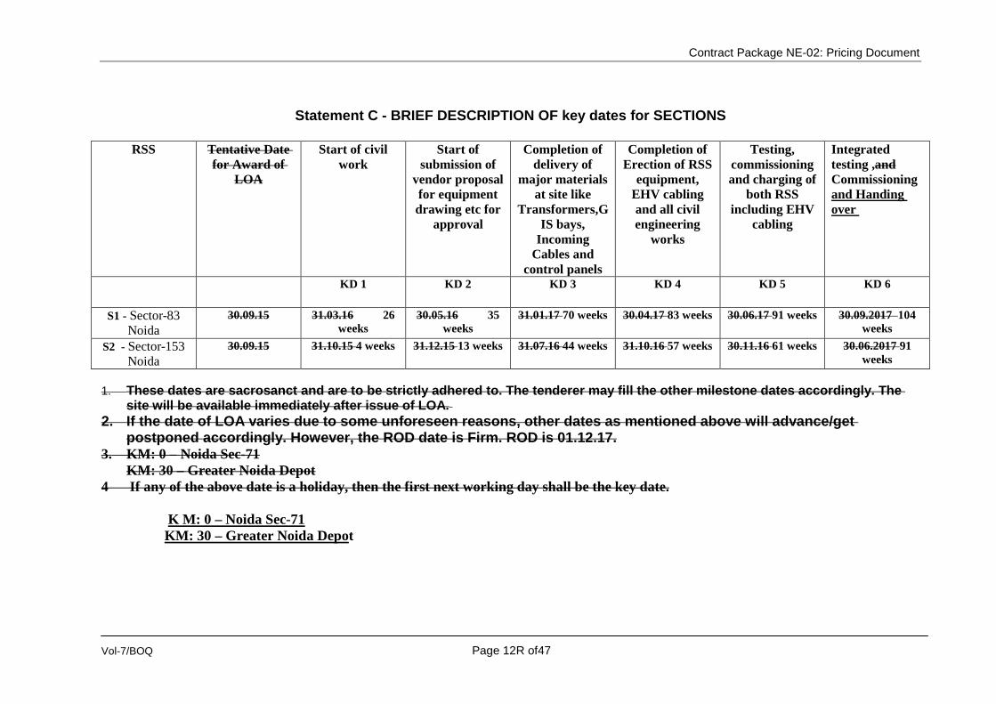
Contract Package NE-02: Pricing Document
Vol-7/BOQ Page 12R of47
Statement C - BRIEF DESCRIPTION OF key dates for SECTIONS
RSS Tentative Date for Award of
LOA
Start of civil work
Start of submission of
vendor proposal for equipment drawing etc for
approval
Completion of delivery of
major materials at site like
Transformers,GIS bays,
Incoming Cables and
control panels
Completion of Erection of RSS
equipment, EHV cabling and all civil engineering
works
Testing, commissioning and charging of
both RSS including EHV
cabling
Integrated testing ,and Commissioning and Handing over
KD 1 KD 2 KD 3 KD 4 KD 5 KD 6
S1 - Sector-83 Noida
30.09.15 31.03.16 26 weeks
30.05.16 35 weeks
31.01.17 70 weeks 30.04.17 83 weeks 30.06.17 91 weeks 30.09.2017 104 weeks
S2 - Sector-153 Noida
30.09.15 31.10.15 4 weeks 31.12.15 13 weeks 31.07.16 44 weeks 31.10.16 57 weeks 30.11.16 61 weeks 30.06.2017 91 weeks
1. These dates are sacrosanct and are to be strictly adhered to. The tenderer may fill the other milestone dates accordingly. The
site will be available immediately after issue of LOA. 2. If the date of LOA varies due to some unforeseen reasons, other dates as mentioned above will advance/get
postponed accordingly. However, the ROD date is Firm. ROD is 01.12.17. 3. KM: 0 – Noida Sec-71
KM: 30 – Greater Noida Depot 4 If any of the above date is a holiday, then the first next working day shall be the key date. K M: 0 – Noida Sec-71
KM: 30 – Greater Noida Depot

Contract Package NE-02: Pricing Document
Vol-7/BOQ Page 13R of47
Design, Detail Engineering, Manufacture, Supply, Installation, Testing and Commissioning 132KV receiving Cum-25 kV AC Traction Cum- 33 kV Auxiliary Main Sub Stations and EHV cabling for Noida-Greater Noida Corridors of Delhi Mass Rapid Transport System Project Phase-3
CONTRACT PACKAGE – NE-02
Statement D
Corridor S1-- Sector-83 Noida RSS
Corridor S2-- Sector-153 Noida RSS

Contract Package NE-02: Pricing Document
Vol-7/BOQ Page 14R of47
Corridor S1 - Sector-83 Noida RSS
This Cost Centre comprises all those obligations and ongoing activities throughout the Contract not associated directly with any other Cost Centre. This Cost Centre A comprises all activities relating to the detailed design of 132KV, 33KV and 25kV systems, civil work and other associates work to complete Receiving substation of Sector-83 Noida.
COST CENTRE A -- DETAILED DESIGN
MILE STONE NO.
WORK DESCRIPTION Apportioned Amount Weeks for completion of Milestone from LOA
Date MILESTONE ACTIVITY Amount in Foreign Currency
Amount in Indian Rupees
(RSS and EHV Cabling Works etc. to comply contract specification for completion of RSS work and other related works)
A1 Preliminary design and specifications
A2 Final design and specifications
A3 Schedule of materials
A4 “Good for Construction drawing as per GS”
A5 "As-built Drawings"
A6 Any other item(s) considered necessary to comply with the Scope of Work
COST CENTRE TOTAL CARRIED TO SECTION SUMMARY

Contract Package NE-02: Pricing Document
Vol-7/BOQ Page 15R of47
Corridor S1 - Sector-83 Noida RSS
This Cost Centre comprises all those obligations and ongoing activities throughout the Contract not associated directly with any other Cost Centre. This includes but is not limited to receipt/ delivery of following equipment for section S1 Sector-83 Noida RSS after type test, factory acceptance
test, provision of bank guarantee and proof of insurance:
COST CENTRE B -- MANUFACTURE AND DELIVERY
MILE STONE NO.
WORK DESCRIPTION Apportioned Amount Weeks for completion of Milestone from LOA
Date MILESTONE ACTIVITY Amount in Foreign Currency
Amount in Indian Rupees
Obtain the ”Notice of No Objection” or “Notice of No Objection subject to…” from the Engineer for each of the following Milestone activities after: • Certification of type tests • Certification of factory acceptance test • Provision of Bank guarantee • Proof of insurance
**B1 Delivery of 132KV incoming cables, Joints, Terminations, Bonding kits with SVL, OFC cable as per contract specification at Contractor’s premises in Noida.
D + 44
B2
Delivery of 132KV GIS type indoor switchgears two incoming, four outgoing and one coupling bays including the PT, CT and other associated equipment as per contract specification at Contractor’s premises in Noida.
D + 44
B3
Delivery of Sub-station automation (SAS) control relay panels with IED type BCU & BPU for complete incoming,outgoing and coupling bays and necessary other associated hardware required as per contract specification for 132KV/33KV/25KV systems at Contractor’s premises in Noida.
D + 44
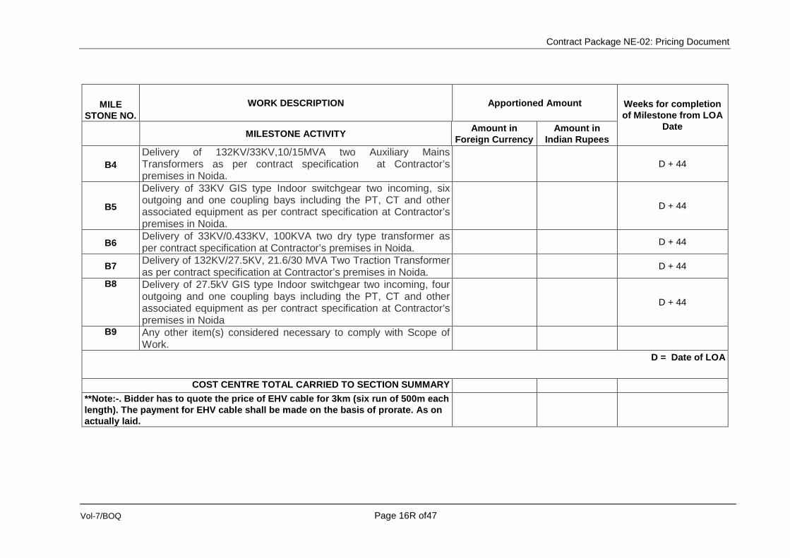
Contract Package NE-02: Pricing Document
Vol-7/BOQ Page 16R of47
MILE STONE NO.
WORK DESCRIPTION Apportioned Amount Weeks for completion of Milestone from LOA
Date MILESTONE ACTIVITY Amount in Foreign Currency
Amount in Indian Rupees
B4 Delivery of 132KV/33KV,10/15MVA two Auxiliary Mains Transformers as per contract specification at Contractor’s premises in Noida.
D + 44
B5
Delivery of 33KV GIS type Indoor switchgear two incoming, six outgoing and one coupling bays including the PT, CT and other associated equipment as per contract specification at Contractor’s premises in Noida.
D + 44
B6 Delivery of 33KV/0.433KV, 100KVA two dry type transformer as per contract specification at Contractor’s premises in Noida.
D + 44
B7 Delivery of 132KV/27.5KV, 21.6/30 MVA Two Traction Transformer as per contract specification at Contractor’s premises in Noida.
D + 44
B8 Delivery of 27.5kV GIS type Indoor switchgear two incoming, four outgoing and one coupling bays including the PT, CT and other associated equipment as per contract specification at Contractor’s premises in Noida
D + 44
B9 Any other item(s) considered necessary to comply with Scope of Work.
D = Date of LOA
COST CENTRE TOTAL CARRIED TO SECTION SUMMARY **Note:-. Bidder has to quote the price of EHV cable for 3km (six run of 500m each length). The payment for EHV cable shall be made on the basis of prorate. As on actually laid.

Contract Package NE-02: Pricing Document
Vol-7/BOQ Page 17R of47
Corridor S1 - Sector-83 Noida RSS
This Cost Centre comprises all those obligations and ongoing activities throughout the Contract not associated directly with any other Cost Centre. This includes but is not limited to Delivery to Site from Contractor's premises in Noida, Submission of Installation,testing Plan and procedures, Installation Drawings, inspection of equipment and Site preparations, Pre- installation tests, Installation of equipment, Post-installation tests, energisation and any other item(s) considered necessary to comply with the scope of work for:
COST CENTRE C – INSTALLATION, SITE TESTING AND ENERGISATION
MILE
STONE NO.
WORK DESCRIPTION Apportioned Amount
MILESTONE ACTIVITY Amount in Foreign Currency
Amount in Indian Rupees
Obtain the ”Notice of No Objection” or “Notice of No Objection subject to…” from the Engineer for each of:
C1 Delivery to Site from Contractor's premises in Noida, making cable path as per civic agency approval, laying, Testing (includes pre-installation tests and post installation tests) and energisation of 132KV incoming cables as per contract specification.
C2 Delivery to Site from Contractor's premises in Noida, Installation and Testing (includes pre-installation tests and post installation tests) and energisation of 132KV GIS type indoor switchgears two incoming, four outgoing and one coupling bays including the PT, CT and other associated equipment as per contract specification.
C3 Delivery to Site from Contractor's premises in Noida, Installation and Testing (includes pre-installation tests and post installation tests) and energisation of complete Sub-station automation (SAS) control relay panels with IED type BCU & BPU for all incoming, outgoing and one coupling bays and necessary other associated hardware required as per contract specification for 132KV/33KV/25KV systems

Contract Package NE-02: Pricing Document
Vol-7/BOQ Page 18R of47
MILE STONE NO.
WORK DESCRIPTION Apportioned Amount
MILESTONE ACTIVITY Amount in Foreign Currency
Amount in Indian Rupees
C4 Delivery to Site from Contractor's premises in Noida, Installation and Testing (includes pre-installation tests and post installation tests) and energisation of 132KV/33KV,10/15MVA two Auxiliary Mains Transformer including all other associated equipments as per contract specification
C5 Delivery to Site from Contractor's premises in Noida, Installation and Testing (includes pre-installation tests and post installation tests) and energisation of 33KV GIS type Indoor switchgear two incoming, six outgoing and one coupling bays including the PT, CT and other associated equipment as per contract specification.
C6 Delivery to Site from Contractor's premises in Noida, Installation and Testing (includes pre-installation tests and post installation tests) and energisation of 33KV/0.433KV, 100KVA two dry type transformer as per contract specification
C7 Delivery to Site from Contractor’s premises in Noida, Installation and Testing (includes pre-installation tests and post installation tests) and energisation of 132KV/27.5KV, 21.6/30MVA two Traction Transformers as per contract specification.
C8 Delivery to Site from Contractor’s premises in Noida, Installation and Testing (includes pre-installation tests and post installation tests) and energisation of 27.5kV GIS type Indoor switchgear two incoming, four outgoing and one coupling bays including the PT, CT and other associated equipment as per contract specification
C9 Delivery to Site from Contractor’s premises in Noida, Installation and Testing (includes pre-installation tests and post installation tests) and energisation of 25kV Traction cable,33KV power cable,3.3KV return current cable, LV cables and control cables for all equipment of RSS including straight through joints ,if any and all type of termination as per contract specification..
C10 Delivery to Site from Contractor's premises in Noida, Installation and Testing (includes pre-installation tests and post installation tests) and energisation of all equipment for Earthing & Bonding and buried copper material bar including Thermosetting weld & cables etc as per contract specification.

Contract Package NE-02: Pricing Document
Vol-7/BOQ Page 19R of47
MILE STONE NO.
WORK DESCRIPTION Apportioned Amount
MILESTONE ACTIVITY Amount in Foreign Currency
Amount in Indian Rupees
C11 Delivery to Site from Contractor's premises in Noida, Installation and Testing (includes pre-installation tests and post installation tests) and energisation of indoor ACDB, Battery charger cum DCDB and battery, EOT crane, Earthquake sensor and all other items required for completion of RSS as per contract speculation
C12 Any other item(s) considered necessary to comply with the Scope of Work
COST CENTRE TOTAL CARRIED TO SECTION SUMMARY

Contract Package NE-02: Pricing Document
Vol-7/BOQ Page 20R of47
Corridor S1 - Sector-83 Noida RSS
This Cost Centre comprises all those obligations and ongoing activities throughout the Contract not associated directly with any other Cost Centre.
This Cost Centre D comprises all activities relating to the Civil work required for completion of 132KV, 33KV and 25kV Systems, cables, substation building and other associates work to complete Receiving substation of Sector-83 Noida.
COST CENTRE D – Civil work
MILE STONE NO. WORK DESCRIPTION Apportioned Amount
MILESTONE ACTIVITY Amount in Foreign Currency
Amount in Indian Rupees
Civil work etc to comply contract specification for completion of RSS work and other related works.
D1 Completion of civil work for control room building as per contract specification and requirement to complete Receiving substation including facilities installations
D2 Completion of civil work for Boundary wall as per contract specification and requirement to complete Receiving substation.
D3
Completion of civil work like Transformer foundation, baffle wall, cable trench, Guard room, all type of drainage arrangement, road and other required work as per contract specification and requirement to complete Receiving substation.
D4 Any other item(s) considered necessary to comply with the Scope of Work
COST CENTRE TOTAL CARRIED TO SECTION SUMMARY

Contract Package NE-02: Pricing Document
Vol-7/BOQ Page 21R of47
Corridor S1 - Sector-83 Noida RSS
This Cost Centre comprises all those obligations and ongoing activities throughout the Contract not associated directly with any other Cost Centre. This includes but is not limited to:
COST CENTRE E – SYSTEM ACCEPTANCE TESTS, INTEGRATED TESTING AND COMMISSIONING
MILE- STONE
NO.
WORK DESCRIPTION Apportioned Amount Weeks for completion of Milestone from LOA
Date MILESTONE ACTIVITY Amount in Foreign Currency
Amount in Indian Rupees
E1 Obtain the “Notice of No Objection” or “Notice of No Objection Subject to ---“from the Engineer for the System Acceptance Test (SAT) , Integrated Testing and Commissioning of a complete protection system.
E2 Obtain the “Notice of No Objection” or “Notice of No Objection Subject to ---“ from the Engineer for the System Acceptance Test (SAT) , Integrated Testing and Commissioning of complete Substation Automation System.
E3 Any other item(s) considered necessary to comply with the Scope of Work.
COST CENTRE TOTAL CARRIED TO SECTION SUMMARY

Contract Package NE-02: Pricing Document
Vol-7/BOQ Page 22R of47
Corridor S2 - Sector-153 Noida RSS
This Cost Centre comprises all those obligations and ongoing activities throughout the Contract not associated directly with any other Cost Centre. This Cost Centre A comprises all activities relating to the detailed design of 132KV, 33KV and 25kV systems, civil work and other associates work to complete Receiving substation of Sector-153 Noida.
COST CENTRE A -- DETAILED DESIGN
MILE STONE NO.
WORK DESCRIPTION Apportioned Amount Weeks for completion of Milestone from LOA
Date MILESTONE ACTIVITY Amount in Foreign Currency
Amount in Indian Rupees
(RSS and EHV Cabling Works etc. to comply contract specification for completion of RSS work and other related works)
A1 Preliminary design and specifications
A2 Final design and specifications
A3 Schedule of materials
A4 “Good for Construction drawing as per GS”
A5 "As-built Drawings"
A6 Any other item(s) considered necessary to comply with the Scope of Work
COST CENTRE TOTAL CARRIED TO SECTION SUMMARY

Contract Package NE-02: Pricing Document
Vol-7/BOQ Page 23R of47
Corridor S2 - Sector-153 Noida RSS
This Cost Centre comprises all those obligations and ongoing activities throughout the Contract not associated directly with any other Cost Centre. This includes but is not limited to receipt/ delivery of following equipment for section S2 Sector-153 Noida RSS after type test, factory acceptance
test, provision of bank guarantee and proof of insurance:
COST CENTRE B -- MANUFACTURE AND DELIVERY( To be completed before 01.08.16)
MILE STONE NO.
WORK DESCRIPTION Apportioned Amount Weeks for completion of Milestone from LOA
Date MILESTONE ACTIVITY Amount in Foreign Currency
Amount in Indian Rupees
Obtain the ”Notice of No Objection” or “Notice of No Objection subject to…” from the Engineer for each of the following Milestone activities after: • Certification of type tests • Certification of factory acceptance test • Provision of Bank guarantee • Proof of insurance
**B1 Delivery of 132KV incoming cables as per contract specification at Contractor’s premises in Noida.
D + 44
B2
Delivery of 132KV GIS type indoor switchgears two incoming, four outgoing and one coupling bays including the PT, CT and other associated equipment as per contract specification at Contractor’s premises in Noida.
D + 44
B3
Delivery of Sub-station automation (SAS) control relay panels with IED type BCU & BPU for complete incoming, outgoing and coupling bays and necessary other associated hardware required as per contract specification for 132KV/33KV/25KV systems at Contractor’s premises in Noida.
D + 44

Contract Package NE-02: Pricing Document
Vol-7/BOQ Page 24R of47
MILE STONE NO.
WORK DESCRIPTION Apportioned Amount Weeks for completion of Milestone from LOA
Date MILESTONE ACTIVITY Amount in Foreign Currency
Amount in Indian Rupees
B4 Delivery of 132KV/33KV,10/15MVA two Auxiliary Mains Transformers as per contract specification at Contractor’s premises in Noida.
D + 44
B5
Delivery of 33KV GIS type Indoor switchgear two incoming, six outgoing and one coupling bays including the PT, CT and other associated equipment as per contract specification at Contractor’s premises in Noida.
D + 44
B6 Delivery of 33KV/0.433KV, 200KVA two dry type transformers as per contract specification at Contractor’s premises in Noida.
D + 44
B7 Delivery of 132KV/27.5KV, 21.6/30MVA Two Traction Transformer as per contract specification at Contractor’s premises in Noida.
D + 44
B8 Delivery of 27.5 kV GIS type Indoor switchgear two incoming, four outgoing and one coupling bays including the PT, CT and other associated equipment as per contract specification at Contractor’s premises in Noida
D + 44
B9 Any other item(s) considered necessary to comply with Scope of Work.
D + 44
D = Date of LOA
COST CENTRE TOTAL CARRIED TO SECTION SUMMARY **Note:-. Bidder has to quote the price of EHV cable for 3km (six run of 500m each length). The payment for EHV cable shall be made on the basis of prorate as on actually laid.

Contract Package NE-02: Pricing Document
Vol-7/BOQ Page 25R of47
Corridor S2 - Sector-153 Noida RSS
This Cost Centre comprises all those obligations and ongoing activities throughout the Contract not associated directly with any other Cost Centre. This includes but is not limited to Delivery to Site from Contractor's premises in Noida, Submission of Installation,testing Plan and procedures, Installation Drawings, inspection of equipment and Site preparations, Pre- installation tests, Installation of equipment, Post-installation tests, energisation and any other item(s) considered necessary to comply with the scope of work for:
COST CENTRE C – INSTALLATION, SITE TESTING AND ENERGISATION
MILE STONE WORK DESCRIPTION Apportioned Amount
NO. MILESTONE ACTIVITY Amount in Foreign
Currency Amount in Indian
Rupees
Obtain the ”Notice of No Objection” or “Notice of No Objection subject to…” from the Engineer for each of:
C1
Delivery to Site from Contractor's premises in Noida, making cable path as per civic agency approval,laying, Testing (includes pre-installation tests and post installation tests) and energisation of 132KV incoming cables as per contract specification
C2
Delivery to Site from Contractor's premises in Noida, Installation and Testing (includes pre-installation tests and post installation tests) and energisation of 132KV GIS type indoor switchgears two incoming, four outgoing and one coupling bays including the PT, CT and other associated equipment as per contract specification
C3
Delivery to Site from Contractor's premises in Noida, Installation and Testing (includes pre-installation tests and post installation tests) and energisation of complete Sub-station automation (SAS) control relay panels with IED type BCU & BPU for all incoming,outgoing and one coupling bays and necessary other associated hardware required as per contract specification for 132KV/33KV/25KV systems

Contract Package NE-02: Pricing Document
Vol-7/BOQ Page 26R of47
MILE STONE WORK DESCRIPTION Apportioned Amount
NO. MILESTONE ACTIVITY Amount in Foreign
Currency Amount in Indian
Rupees
C4
Delivery to Site from Contractor's premises in Noida, Installation and Testing (includes pre-installation tests and post installation tests) and energisation of 132KV/33KV,10/15MVA two Auxiliary Mains Transformer including all other associated equipments as per contract specification
C5
Delivery to Site from Contractor's premises in Noida, Installation and Testing (includes pre-installation tests and post installation tests) and energisation of 33KV GIS type Indoor switchgear two incoming, six outgoing and one coupling bays including the PT, CT and other associated equipment as per contract specification.
C6 Delivery to Site from Contractor's premises in Noida, Installation and Testing (includes pre-installation tests and post installation tests) and energisation of 33KV/0.433KV, 100KVA two dry type transformer as per contract specification
C7
Delivery to Site from Contractor’s premises in Noida, Installation and Testing (includes pre-installation tests and post installation tests) and energisation of 132KV/27.5KV, 21.6/30MVA two Traction Transformers as per contract specification.
C8
Delivery to Site from Contractor’s premises in Noida, Installation and Testing (includes pre-installation tests and post installation tests) and energisation of 27.5kV GIS type Indoor switchgear two incoming, four outgoing and one coupling bays including the PT, CT and other associated equipment as per contract specification
C9
Delivery to Site from Contractor’s premises in Noida, Installation and Testing (includes pre-installation tests and post installation tests) and energisation of 25kV Traction cable,33KV power cable,3.3KV return current cable, LV cables and control cables for all equipment of RSS including straight through joints ,if any and all type of termination as per contract specification..
C10
Delivery to Site from Contractor's premises in Noida, Installation and Testing (includes pre-installation tests and post installation tests) and energisation of all equipment for Earthing & Bonding and buried copper material bar including Thermosetting weld & cables etc as per contract specification.

Contract Package NE-02: Pricing Document
Vol-7/BOQ Page 27R of47
MILE STONE WORK DESCRIPTION Apportioned Amount
NO. MILESTONE ACTIVITY Amount in Foreign
Currency Amount in Indian
Rupees
C11
Delivery to Site from Contractor's premises in Noida, Installation and Testing (includes pre-installation tests and post installation tests) and energisation of indoor internal LED type lighting, external LED type lighting with High mast, Direct stroke lightening protection, VRV type air conditioners, fire detection and fire fighting equipments as per fire by-laws, ACDB, Battery charger cum DCDB and battery, EOT crane, Earthquake sensor and all other items required for completion of RSS as per contract speculation
C12 Any other item(s) considered necessary to comply with the Scope of Work
COST CENTRE TOTAL CARRIED TO SECTION SUMMARY

Contract Package NE-02: Pricing Document
Vol-7/BOQ Page 28R of47
Corridor S2 - Sector-153 Noida RSS
This Cost Centre comprises all those obligations and ongoing activities throughout the Contract not associated directly with any other Cost Centre.
This Cost Centre D comprises all activities relating to the Civil work required for completion of 132KV, 33KV and 25kV Systems,cables,substation building and other associates work to complete Receiving substation of Sector-153 Noida.
COST CENTRE D – Civil work
MILE STONE NO.
WORK DESCRIPTION Apportioned Amount Weeks for completion of Milestone from LOA
Date MILESTONE ACTIVITY Amount in Foreign Currency
Amount in Indian Rupees
Civil work etc to comply contract specification for completion of RSS work and other related works.
D1 Completion of civil work for control room building as per contract specification and requirement to complete Receiving substation including facilities installations
D2 Completion of civil work for Boundary wall as per contract specification and requirement to complete Receiving substation.
D3
Completion of civil work like Transformer foundation, baffle wall, cable trench, Guard room, all type of drainage arrangement, road and other required work as per contract specification and requirement to complete Receiving substation.
D4 Any other item(s) considered necessary to comply with the Scope of Work
COST CENTRE TOTAL CARRIED TO SECTION SUMMARY

Contract Package NE-02: Pricing Document
Vol-7/BOQ Page 29R of47
Corridor S2 - Sector-153 Noida RSS
This Cost Centre comprises all those obligations and ongoing activities throughout the Contract not associated directly with any other Cost Centre. This includes but is not limited to:
COST CENTRE E – SYSTEM ACCEPTANCE TESTS, INTEGRATED TESTING AND COMMISSIONING
MILE- STONE
NO.
WORK DESCRIPTION Apportioned Amount Weeks for completion of Milestone from LOA
Date MILESTONE ACTIVITY Amount in Foreign Currency
Amount in Indian Rupees
E1 Obtain the “Notice of No Objection” or “Notice of No Objection Subject to ---“from the Engineer for the System Acceptance Test (SAT) , Integrated Testing and Commissioning of a complete protection system.
E2 Obtain the “Notice of No Objection” or “Notice of No Objection Subject to ---“ from the Engineer for the System Acceptance Test (SAT) , Integrated Testing and Commissioning of complete Substation Automation System.
E3 Any other item(s) considered necessary to comply with the Scope of Work.
COST CENTRE TOTAL CARRIED TO SECTION SUMMARY

Contract Package NE-02: Pricing Document
Vol-7/BOQ Page 30R of47
Design, Detail Engineering, Manufacture, Supply, Installation, Testing and Commissioning 132KV receiving Cum-25 kV AC Traction Cum- 33 kV Auxiliary Main Sub Stations and EHV cabling for Noida-Greater Noida Corridors of Delhi Mass Rapid Transport System Project Phase-3
CONTRACT PACKAGE – NE-02
STATEMENT - E SECTION—MISCELLANEOUS
Common for both complete work for Corridor S1-- Sector-83 & Corridor S2-- Sector-153

Contract Package NE-02: Pricing Document
Vol-7/BOQ Page 31R of47
SECTION -- MISCELLANEOUS This Cost Centre comprises all those obligations and on going activities throughout the Contract not associated directly with any other Cost Centre. This includes but is not limited to:
COST CENTRE A – PRELIMINARIES AND GENERAL REQUIREMENTS
MILE STONE
NO.
WORK DESCRIPTION Apportioned Amount Weeks for completion of Milestone from LOA
Date MILESTONE ACTIVITY Amount in
Foreign Currency Amount in Indian
Rupees
Obtain the ”Notice of No Objection” or “Notice of No Objection subject to…” from the Engineer for:
A1 Works Program for complete Contract.
A2 Project Management Plan
A3 Interface Management Plan and Detailed Interface Document
A4 Design Submission Program
A5 Quality Assurance Plan
A6 Safety Assurance Plan & Site Safety Plan.
A7 Environment Plan
A8 Inspection, Testing, Commissioning and Integrated Testing Plan
A09 Any other item(s) considered necessary by the Contractor to comply with the Scope of Work.
COST CENTRE TOTAL CARRIED TO SECTION SUMMARY

Contract Package NE-02: Pricing Document
Vol-7/BOQ Page 32R of47
SECTION -- MISCELLANEOUS This Cost Centre comprises all those obligations and ongoing activities throughout the Contract not associated directly with any other Cost Centre. This shall include but not be limited to:
COST CENTRE B – TRAINING
STONE NO.
WORK DESCRIPTION Apportioned Amount Weeks for completion of Milestone from LOA
Date
MILESTONE ACTIVITY Amount in Foreign Currency
Amount in Indian Rupees
Obtain the “Notice of No Objection” or “Notice of No Objection Subject to ---“ from the Engineer for:
N/A
B1 Training of Employer’s personnel (9 man-weeks) overseas in Contractor/Sub-Contractor’s Works and MRTS.
N/A
B2 Provision of Contractor’s Instructors (7 man-weeks) for training of Employer’s operating personnel in India.
N/A
B3 Provision of Contractor’s Instructors (8 man-weeks) for Training of Employer’s maintenance personnel in India.
N/A
B4 Submission of Training Manuals in Original plus five hard copies and in electronic format.
N/A
B5 Any other item(s) necessary to comply with the Scope of Work. N/A COST CENTRE TOTAL CARRIED TO SECTION MS SUMMARY N/A
Notes:
The Tenderer shall not complete the column “Weeks for completion of Milestone from Commencement Date. The dates for the operation of these Milestone Activities will be at the discretion of the Employer. The travel, boarding and lodging expenses for the Employer’s trainees sent overseas will be borne by the Employer.

Contract Package NE-02: Pricing Document
Vol-7/BOQ Page 33R of47
SECTION -- MISCELLANEOUS This Cost Centre comprises all those obligations and ongoing activities throughout the Contract not associated directly with any other Cost Centre. This shall include but not be limited to supply of spares for complete work under S1 & S2
COST CENTRE C – SPARES
MILE- STONE
NO.
WORK DESCRIPTION Apportioned Amount Weeks for completion of Milestone from LOA Date
MILESTONE ACTIVITY Amount in Foreign Currency
Amount in Indian Rupees
Obtain the “Notice of No Objection” or “Notice of No Objection Subject to ---“ from the Engineer for delivery of the following in accordance with the Employer’s Requirements:
C1 Delivery to Site/designated store the spares as per Table-A spare part list and Table-B Tools & plants list attached
C2 Any other item(s) considered necessary to comply with the Scope of Work.
COST CENTRE TOTAL CARRIED TO SECTION SUMMARY

Contract Package NE-02: Pricing Document
Vol-7/BOQ Page 34R of47
SECTION -- MISCELLANEOUS This Cost Centre comprises all those obligations and ongoing activities throughout the Contract not associated directly with any other Cost Centre. The
Experts will be required during the interval commencing from start of service trials on the Section until six months after Revenue Operation Date (ROD) of
the section.
COST CENTRE D – SUPERVISION OF MAINTENANCE
MILE- STONE
NO.
WORK DESCRIPTION Apportioned Amount Weeks for completion of Milestone from LOA Date
MILESTONE ACTIVITY Amount in Foreign Currency
Amount in Indian Rupees
Obtain the “Notice of No Objection” or “Notice of No Objection Subject to ---“ from the Engineer for completion of the following in accordance with the Employer’s Requirements:
N/A
D1* Supervision of Maintenance (40 man months)* N/A
COST CENTRE TOTAL CARRIED TO SECTION MS SUMMARY N/A
* This excludes Contractor’s obligations and responsibilities during the Defects Liability Period and AMC as applicable.
1. The deployment of the experts under this Cost Centre may not be continuous and they may be required to supervise the maintenance in short periods at a time. The number of man months of experts shall, however, not exceed 40 man-months. Payment for this Cost Centre will be made on man months basis.
2. The Tenderer shall not complete the column “Weeks for completion of Milestone from Commencement Date”. 3. The dates for completion of the Milestone Activities will be at the discretion of the Employer.

Contract Package NE-02: Pricing Document
Vol-7/BOQ Page 35R of47
SECTION -- MISCELLANEOUS This Cost Centre comprises all those obligations and ongoing activities throughout the Contract not associated directly with any other Cost Centre. This shall include but not be limited to the Provision of Operating Manuals (hard copies and electronic format) for complete work
COST CENTRE E – MANUALS (The Manuals shall be bilingual in Hindi & English)
MILE- STONE
NO.
WORK DESCRIPTION Apportioned Amount Weeks for
completion of Milestone from
LOA Date
MILESTONE ACTIVITY Amount in
Foreign Currency
Amount in Indian Rupees
Obtain the “Notice of No Objection” Subject to ---“ from the Engineer on delivery of the final Manuals for all RSS equipments including cables before commencement of Integrated Testing and Commissioning of RSS..
E1 Installation Manuals (Original plus five hard copies) and in Electronic Format
E2 Operating Manuals (Original plus five hard copies) and in Electronic Format
E3 Maintenance Manuals (Original plus five hard copies) and in Electronic Format
E4 Subsystems/ Systems spare parts catalogue (Original plus five hard copies) and in Electronic Format.
E5 Any other item(s) considered necessary to comply with the scope of Work.
COST CENTRE TOTAL CARRIED TO SECTION SUMMARY

Contract Package NE-02: Pricing Document
Vol-7/BOQ Page 36R of47
COST CENTRE F- ADDITION/DELETION ITEMS RATE
This Cost Centre comprises all those obligations and ongoing activities throughout the Contract not associated directly with any other Cost Centre. This shall include but not be limited to the Provision of addition OR deletion of any items in the contract for completion of RSS work.
Unit Prices of Items for Addition/Deletion Quantities
Sl. No.
Item Description Unit Quantity Rate Amount in
Foreign Currency
Amount in Indian Rupees
1. 132kV GIS Bay (Incoming bay) Nos 1
2. 132kV GIS Bay (outgoing bay for Auxiliary) Nos 1
3. 33kV GIS Bay (Incoming bay) Nos 1
4. 33kV GIS Bay (outgoing bay) Nos 1
5. 25kV GIS Bay (Incoming bay) Nos 1
6. 25kV GIS Bay (outgoing bay) Nos 1
7. 132kV EHV cable M 500
8. 132kV EHV termination (GIS type) Nos 3
9. 132kV EHV termination (Outdoor type) Nos 3
10. 132 kV EHV cable joints Nos 3
11. Standby Control and monitoring for 132kV,33kV and 25kV as per PS clause 3.5 of PS of chapter 8A of volume 4
Nos 2
NOTE: 1. The unit price shall be an all inclusive fixed price for delivery, installation/laying, testing and commissioning The price will include all
associated accessories and fixtures of the respective items and all duties, taxes, etc. including tax deducted at source. 2. The unit prices shall be valid until the Taking over Certificate of the last Section. 3 The cost quoted shall be used for evaluation of L-1 Bidder.

Contract Package NE-02: Pricing Document
Vol-7/BOQ Page 37R of47
Design, Detail Engineering, Manufacture, Supply, Installation, Testing and Commissioning 132KV receiving Cum-25 kV AC Traction Cum- 33 kV Auxiliary Main Sub Stations and EHV cabling for Noida-Greater Noida Corridors of Delhi Mass Rapid Transport System Project Phase-3
CONTRACT PACKAGE – NE-02
Statement G – Monthly Cash Flows

Contract Package NE-02: Pricing Document
Vol-7/BOQ Page 38R of47
STATEMENT G – Monthly Cash Flows for the Contract
This Document is to be prepared by the Tenderer as per clause C. Milestone Payment Schedule
Note: The amount of Cost Centers B and D of Section Miscellaneous will not be included in the Monthly Cash Flows.

Contract Package NE-02: Pricing Document
Vol-7/BOQ Page 39R of47
Table A (Spare Part List)
Item No. WORK DESCRIPTION Unit Qty
Unit Price Total Price
INR FC. INR FC.
1 132 kV Bushing nos. 1
2
Set of tank gaskets and joints for 132kV / 33kV 30/45 10/15 MVA, 3 phase transformer nos. 1
3 Set of tank gaskets and joints for 132kV / 25kV Traction transformer nos. 1
4 SAS Cubicle, each containing the BCU and BPU equipments, complete
- for Incomer bay nos. 1
- for outgoing transformer bay nos. 2
- for Bus Coupler bay nos. 1
5 Workstation (RAID 5 Server) nos. 2
6 Printer (on the fly type, A4) nos. 1
7 Printer (Laser type, monochrome, A4 & A3) nos. 1

Contract Package NE-02: Pricing Document
Vol-7/BOQ Page 40R of47
Item No. WORK DESCRIPTION Unit Qty
Unit Price Total Price
INR FC. INR FC.
8 Printer (inkjet, colour, part) nos. 2
9 IED nos. 1
10 Programs nos. 1
11 132 kV Cable, 1 drum M 500
12 Straight through joint (Set of 3 for 3 phases) Sets 2
13 Outdoor Sealing end (Set of 3 for 3 phases) Sets 2
14 Disconnecting Link Box for 3 phases (with SVL) Sets 1
15 Arrester (SVL) nos. 2
16 Cross Bonding Link Box ( for 3 phases) nos. 1
17 RCC protection nos. 2
18 Cable Marker nos. 6

Contract Package NE-02: Pricing Document
Vol-7/BOQ Page 41R of47
Table B (Tools and plants List)
Item No. WORK DESCRIPTION Unit Qty
Unit Price Total Price
INR FC. INR FC.
1 Oil Filtration Plant (300 litres capacity) (working off 230V, single phase AC) no. 2
2 Oil Filtration Plant (6000 liters capacity) (working off 415V, 3-phase AC) nos. 1
3 Portable Petrol Start Kerosene Run Generator 5 kVA capacity(415V, 3-phase AC) nos. 1
4
Earthing Network tester, complete with injection transformer, with variable secondary, max current 100A, max voltage 32 V, meters leads and connectors to measure ground resistance, without disconnecting ground conductor.
no. 1
5 AC Ammeters 0-1/3/10/30A, portable type, complete with carrying case. nos. 2
6 AC Ammeters 0-10/30/100/300mA, portable type, complete with carrying case. nos. 2
7 Voltmeters 0-3/10/30/100V, portable type, complete with carrying case. nos. 2
8 Voltmeters 0-30/100/300/600V, portable type, complete with carrying case. nos. 2

Contract Package NE-02: Pricing Document
Vol-7/BOQ Page 42R of47
Item No. WORK DESCRIPTION Unit Qty
Unit Price Total Price
INR FC. INR FC.
9 DC Voltmeters 0-1/3/10/30V, portable type, complete with carrying case. nos. 2
10 DC Voltmeters 0-30/100/300/600V, portable type, complete with carrying case. nos. 2
11 DC Ammeters 0-1/3/10/30mA, portable type, complete with carrying case. nos. 2
12 DC Ammeters 0-0.1/0.3/1/3A, portable type, complete with carrying case. nos. 2
13
Multi-meters with clay on CT for upto 1000 A, Digital type, Data logging with expanded memory, recording upto 10000 events, graphical on screen display and review, download facility to PC with necessary software and test lead sets.
nos. 2
14 Primary Injection Test set, with a rated output of 3000 A at 3V, 1500 A at 6V and 750 A at 12V nos. 1
15 Secondary Injection test set, with a continuously variable voltage of 0-250VAC (capacity 2A) or 0-500VAC (capacity 1A)
nos. 1
16 Electricians standard tool box Complete all types of Spanners, Pliers, & Test Kits. nos. 2
17
Mechanical tool box essentially containing torque wrenches, spanners screw-drivers, rachets hammers Set, L end Key sets , digital screw gauge and digital vernier calliper.
nos. 2

Contract Package NE-02: Pricing Document
Vol-7/BOQ Page 43R of47
Item No. WORK DESCRIPTION Unit Qty
Unit Price Total Price
INR FC. INR FC.
18 SF6 Gas leak detector nos. 1
19
Laptop with necessary cables and preloaded SAS software for connecting to SAS, BCU, BPU provided in the RSS (latest configuration i7 processor or better, 4 GB RAM, 500 GB Hard Disk, latest windows software)
nos 2
20 Helmets nos. 10
21 Safety harness nos. 5
22 Printer cum Scanner (A3 size, colour) nos. 1
23
Cable fault detector, to search and localize the high and low voltage cable faults. The device to be specific, the device shall be of digital type, based on potential distribution method, with selectable input impedance, battery operated, portable and easy to use, capable of precise location of short circuit faults, earth faults including high resistance faults and open circuit faults for Cable from 25kV, 33kV, 132kV
nos. 1
24 Tan-delta tester nos. 2
25 Megger 5000V with downloading facility to PC, 25 Feet extension test leads nos. 2
26 Hipot tester for cables upto 220 kV level. nos. 1

Contract Package NE-02: Pricing Document
Vol-7/BOQ Page 44R of47
Item No. WORK DESCRIPTION Unit Qty
Unit Price Total Price
INR FC. INR FC.
27 Thermal Imaging Camera with color LCD display, range upto 250 ° C, with expandable memory and PC interface.
nos. 1
28 Digital Earth Resistance meter nos. 2
29 Time interval meter suitable to measure closing/opening time of CB nos. 2
30 Contact resistance meter nos. 2
31
Handy kit for substation having high accuracy digital multimeter, contunuity tester, wire stripper & cutter, Banana clips for shorting CT secondary, soldering iron etc
nos. 2
32 CT/PT accuracy tester nos. 1
33
High voltage detector portable type suitable upto 33 kV installations and able to sense presence of HT from a distance to sense presence of HT from a distance of approx. 2 meter.
nos. 2
34 Resonance circuit High Voltage test kit nos. 1
35 Adapter for cable testing as per clause 2.1.1.1.20 of Ch-8A, vol-4 nos 1

Contract Package NE-02: Pricing Document
Vol-7/BOQ Page 45R of47
2
(Annexure-A) Vendor approval Policy
It shall be obligatory for the contractor to obtain Notice of “No Objection” from the Engineer for the selection of the vendors for all items of work,even if the name of the vendor is specified in the contract’s technical submission and the works to be done including the purchase of the material and equipment in accordance with the standards specified in the contracts. In case of vendor selected from the approved list provided in the contract, a. A list of approved vendors is provided at N.A of this contract. These are the vendors, who have
been approved by DMRC in such installation of DMRC commissioned earlier. b. Contractor in general shall use the material of approved make as per approved vendor list unless
specified in BOQ or makes meeting the tender specifications as approved by the Employer's representative.
c. The contractor shall ensure the correct selection of the approved make meeting the specifications and its application. Before placing the order for procurement, the sample of approved make shall be verified for its suitability to the specification and application. In case Employer's representative/ engineer, (whose decision will be final and binding on both parties) considers that the make/ model proposed by the contractor does not meet the tender requirement, the contractor will be required to propose an alternative make acceptable to the Employer's Representative.
d. The contractor will submit a list 'A' of vendors for all the items of the BOQ contract i. The list should include the items for which ,the contractor is proposing the product
of the approved vendor. ii. The contractor will be advised 'No Objection' with following caveat:-
The model etc. to be supplied will be the latest or superior one. The contractor will be required to submit the technical proposal for the scrutiny
iii. For the items, contractor desires to propose new vendor, proposal to be submitted in accordance as List '13'.
iv. The contractor will submit the undertaking that above lists i.e. List 'A' and List B' includes all the items required in the contract.
Vendor to be selected who are capable to provide good after sales services available in Delhi NCR during DLP and thereafter.
Vendor Approval and Selection Procedure 1. In the event of contractor wanting to use alternate makes other than those stipulated, for any
reason, the contractor can send a proposal after ensuring that what he proposes at least meets the specifications both, the quality and safety standard of the stipulated makes, the alternate proposed product should be a proven one. He shall also stand full guarantee to his alternate proposal and if at any stage it is found that the material is not suitable or meeting the tender requirement, the contractor shall replace the material and provide the material from the approved vendor without any additional cost to DMRC. The alternate makes can be used only after an approval accorded by the Employer, whose decision will be final in the matter.
2. The approval of any equipment or product to be used shall be done in two stages:-
A. Stage-I i. Assessment of capability of proposed Vendor to supply a particular equipment or
product, with quality and performance requirements, as required by Specifications as well as other contract conditions. The proposed product should be a proven product in service for at least 3 years.
ii. Assessment of the financial and functional strength of the Vendor to supply the requisite quantity of equipment and product as per delivery schedule acceptable to contractor and engineer to deliver the project in time
B. Stage-II Stage-II called as Technical Submission Approval Stage, selection of Equipment or product from the equipment I products manufactured I supplied by the approved vendor will be done. This stage includes thorough technical assessments about the conformance of the offered equipment / product to the Specifications and other requirements.

Contract Package NE-02: Pricing Document
Vol-7/BOQ Page 46R of47
3
C. To obtain Vendor Approval the Contractor must apply with the four sets of the following documents to the Engineer
i. Company Profile and Experience of the Vendor ii. Clause wise compliance of the relevant Clauses of Specifications. iii. Details of supplies / orders executed in last ten years for the type of equipment / product
offered. Supplies / orders executed for Underground Metro Systems shall be specifically mentioned
iv. Details of the facilities available at the Works / Manufacturing Unit where the proposed equipment / product shall be manufactured.
v. ISO 9000 Certification for the Works / Manufacturing Unit where the proposed equipment / product shall be manufactured (The Works / Manufacturing Unit where the proposed equipment / product shall be manufactured must have ISO 9000 Certification)
vi. Proof regarding compliance to Manufacturer's Qualifications. The offered products must be proven in service.
vii. Audited Financial Statements of the Vendor for the last three years. viii. Type test certificates/ Performance certificate from reputed laboratories
for the proposed type of equipment / products to establish the technical capability of the vendor (In case, specific requirements are mentioned in the relevant sections of Specifications with regard to type testing, same shall also be complied additionally).
ix. The vendor shall not have been blacklisted by any Govt. Agency in India. x. Any other item as required by Employer / Employer's Representative. xi. Contractor must certify the check list provided that vendor Proposal is complete and all the
above documents are available in the Vendor Proposal. In addition, the Contractor must check / certify compliance to the Specifications before forwarding the same.
xii. Incomplete Vendor Proposal will not be treated as a submission and will be returned. xiii. Engineer will give Approval to the Vendor Proposal (received complete with all the
documents mentioned above) expeditiously. xiv. Technical submission shall be accompanied with the calculations / other technical
documents to justify the selection of any particular model of equipment / product, detailed technical features / parameters of the selected product, type test certificates from the accredited laboratories for the offered products, any other document required by the Engineer.
xv. Engineer will give Approval to the Technical Proposal (received complete with all the documents mentioned above) expeditiously.
3. It may be noted that Approval of Vendors as per Point (X) above shall only be done by Employer / Engineer after the award of the work. Vendor submissions shall not be evaluated during the tender evaluation. Conditional Tender offers received from Tenderers with particular Vendors for supply of equipment/ products will not be evaluated during evaluation and will be dealt with after award of the work.
4. It may further be noted that Employer / Engineer shall be under no obligation to accept equipment / products manufactured by the successful Tenderer, unless it meets the entire criterion mentioned above.
For Design and Build Contracts In addition to above, in Design and Build Contracts the following shall also be ensured for the Vendor Approval and Selection:- 1. Proven Design The Contractor shall develop the design based on this specification and on sound proven and reliable engineering practices. The broad design details shall be submitted with technical support data in the technical bid. Detailed calculations shall be submitted to the Engineer during the design process stage for review and approval. 2. Systems and Sub-Systems Manufacturer shall have at least 5 years experience of design and manufacturing of similar system. Proposed systems from the proposed manufacturing unit shall have been in use and have established their satisfactory performance and reliability for 3 years in minimum. All sub-systems, equipments and
major components etc. (hereinafter referred as 'subsystems') shall be state-of-art and of proven design. Proposed Systems/ sub-systems shall have been in use and have established their satisfactory performance and reliability on at least Two mass rapid transit systems (including Railway

Contract Package NE-02: Pricing Document
Vol-7/BOQ Page 47R of47
or Airpots) in revenue service over a period of three years or more either outside the country of origin at an average in two different countries or in DMRC. Systems/ Sub-systems/ components used in DMRC do not get automatically qualified for use unless specifically approved by the Engineer for this project. If required by the Engineer, Contractor shall provide certificate of satisfactory performance for a period of five years or more from the Metro operators. Where similar System/ Sub-systems of a different rating are already proven in service as per the above criteria then the supply shall be based on such sub-systems. All 'sub systems' shall be procured from the approved vendors and sourced from only such manufacturing units that have supplied the sub-systems that fulfill the proven design requirements as above. In case the contractor proposes to use systems or sub-system(s) that do not fulfill the above said criteria then the contractor shall furnish sufficient information to prove the basic soundness and.reliability of the offered systems and sub-system(s) for review of the Engineer. The Engineer's decision on contractor's proposal shall be final and binding. For sourcing the equipment from indigenous manufacturing facilities, following conditions shall be complied:- i. In case the vendor uses his own facilities for indigenization after part supply of equipment from
the approved manufacturing unit, no change in design, component type/make, quality standards, manufacture procedure, etc. shall be made without specific approval of the Engineer.
ii. In case OEM wants to use manufacturing facilities in India (other than his own) for items for which the OEM has been approved, it shall enter into an agreement with such selected Indian equipment manufacturer and obtain prior approval from DMRC. No change in composition, rating, type, model no., manufacturing process, quality standards, design, etc. and make of the components used in assemblies/sub-assemblies of such equipment as manufactured by the approved parent vendor shall be made without specific approval of the Engineer.
iii. In case OEM wishes to change/make/type specifications, etc. of any sub-components for supplies to be sourced from Indian facility, specific prior approval of the Engineer shall be obtained for changes made, model, specification, etc. Responsibility for obtaining such prior approval shall rest solely with the contractor.
Format for submitting the vendor approval request shall be given to the contractor during initial stages after award of contract and approved format shall be followed throughout the contract.period.

Contract Package NE-02: Pricing Document
Vol-7/BOQ Page 47A of47
Checklist Sl. No. Description Remarks Page No
A. GENERAL 1 Contract No. 2 Name of Contract 3 Name & Address of the Contractor
4 Total Value of Contract 5 Details of the works / equipment for which
the Vendor / Sub-Contractor is proposed
6 Name of the proposed Vendor / Sub-Contractor
7 Address of the proposed Vendor / Sub-Contractor
8 Name , Designation and details of the Contact Person of the Vendor / Sub-Contractor
9 Total Value of work proposed to be done by Vendor / Sub-Contractor
B. COMPANY PROFILE & EXPERIENCE OF VENDOR
1 Type of proposed Vendor / Sub-Contractor (Proprietor , Partnership , Pvt. Ltd. or Limited Company
2 Date of Incorporation of the Company 3 Experience of the proposed Vendor /
Sub-Contractor for the proposed scope of work
4 Address of Manufacturing Facilities for the item
5 Annual Manufacturing capacity for proposed item.
6 Organizational details of the Vendor / Sub-Contractor
7 Manpower Strength of the Company 8 Are 'in-house' Design, Testing and R&D
facilities available? (If 'Yes' , please provide details)
C. CLAUSE BY CLAUSE COMPLIANCE OF THE RELEVANT CLAUSE OF SPECIFICATIONS (GS & PS) SUBMITTED

Contract Package NE-02: Pricing Document
Vol-7/BOQ Page 47B of47
1 Is there any deviation from the contract conditions / specifications. We hereby confirm that all implicit and
explicit deviations, comments and
remarks mentioned elsewhere in our
proposal shall be treated as NULL and
VOID and stand withdrawn. We hereby
confirm that but for the deviations noted in
this Appendix-A our offer is fully and truly
compliant.
2 Reasons for the deviation (if any) 3 Is there any price adjustment for the
deviation?
D. DETAILS OF WORK EXPERIENCE IN PROVIDING SIMILAR PRODUCT / SERVICES IN LAST 10 YEARS
(Enclose copy of the Work Completion Certificates / Product Performance Certificate from the client indicating the scope of work, make & model of the component , quantity , total value , year of completion , installation and the remark on performance). Certificate must be on the letter head of the client and must contain the contact details of the client's representative for verification.
a Summary of Certificate – 1 b Summary of Certificate – 2 c Summary of Certificate – 3 d Summary of Certificate – 4 e Summary of Certificate – 5 Has the Vendor / Sub-Contractor been
blacklisted by any Public Sector Undertaking , State Govt. / Central Govt. Department or Agency in India or Abroad
a If 'Yes' , please provide the details 2 Has the proposed component / material
been used in Delhi Metro Rail Corporation. (If 'Yes', please provide the details thereof, accompanied by the experience certificate from DMRC.)
3 Has the proposed component / material been used in any other Metro System worldwide. (If 'Yes', please provide the details thereof , accompanied by the client certificate.)

Contract Package NE-02: Pricing Document
Vol-7/BOQ Page 47C of47
E. DETAILS OF THE FACILITIES AVAILABLE AT WORKS / MANUFACTURING UNIT WHERE THE PROPOSED EQUIPMENT / PRODUCT SHALL BE MANUFACTURED
F. QUALITY CERTIFICATE 1 Independent Certification / Accreditation
available for the manufacturing unit (e.g. ISO 9001, etc.)
a Number & Date of Issuance of Certificate b Certificate issued by c Validity of the Certificate d Scope for which certification has been
issued
2 Details of In-House Testing Facilities a The Test Facility is as per which Indian or
International Standard
b Is this as per the Standard prescribed in Contract
c Is the Facility accredited by an independent agency
d Name of LAB with which In-House Facility accredited
G. FINANCIAL DATA 1 Audited Financial Statement for last 3
years submitted
2 Net worth of the Vendor / Sub-Contractor 3 Is Net worth of Vendor / Sub-Contractor
adequate (i.e., > Total Value of Proposed Work / 1.5 years)
4 Profitability (should be positive in last 3 years)
5 Liquidity of the Vendor / Sub-Contractor 6 Is Liquidity of Vendor / Sub-Contractor
adequate? (Liquidity must be adequate to meet the cash-flow required for minimum 3 months or the main contractor to submit the Undertaking / Guarantee to ensure adequate cash-flow)

Contract Package NE-02: Pricing Document
Vol-7/BOQ Page 47D of47
H. TYPE TEST CERTIFICATES (Type Test certificates from laboratories
for the proposed type of equipment /to establish the technical capability of the Vendor) (Incase, specific requirements are mentioned in the relevant specifications with regard to Type Testing, same shall also be complied additionally).
1 Is the Type Test Certificates provided? 2 Validity Date of Test Certificate? 3 Is the Test Report from an reputed
laboratory? (If ‘Yes’, please attach details of the same).
4 Test Report is accompanied by the Calibration Reports of test-set-up / instruments used , etc.
5 Is the certificate/report for the proposed model?
6 Is the Test Certificate as per the standard stipulated in the contract?
7 Is the Test Certificate not more than 5 or 10 years old? (as applicable in the contract)
I. TIME PERIOD FOR DELIVERY OF MATERIAL OR FOR EXECUTION OF THE PROPOSED WORK
a Work Program / Delivery Schedule submitted
b What are the critical activities? c Does the proposed delivery schedule /
work program meets the Contract Requirement?
J. AFTER SALES SERVICE
1 List of recommended Spares and life is enclosed
2 Details of After Sales Support system in Delhi
a List of authorized dealers of Spares is enclosed
b Price list of Spares is enclosed? c Vendor's Undertaking confirming that
Spares will be available during the lifetime of the product , irrespective of up gradation / phasing-out of the component / item is enclosed.
d Back-to-back agreement between main contractor and Vendor for providing full support during Defect Liability Period. (Copy of the formal agreement may be submitted after approval of Vendor).

Contract Package NE-02: Pricing Document
Vol-7/BOQ Page 47E of47
E Is confirmation of contractor and vendor complying to the requirements of SCC clause 60 enclosed.
K. TOOLS & TACKLES
(applicable only for subcontractor proposal)
a Details of Tools & Tackles available with the proposed Sub-Contractor for this work
b Copy of valid Calibration Certificates is submitted
c Copy of Test Certificates , Fitness Certificates , etc.
L. MANPOWER
(applicable only for sub-contractor proposal)
a Details of Manpower proposed b Is manpower proposed has relevant
experience of work execution?
c Has the Firms proposed any Safety organization? Please provide the details
M. ANY OTHER DETAILS RELEVANT TO THE PROPOSAL
a Weather Handling, Storage, protection and installation guidelines issued by OEM are furnished. We confirm to comply with the same.
b Whether copies of relevant IS/IEC Enclosed
c Service life certificate from OEM attached.
d Factory acceptance test plan We confirm that the applicable tests as per contract and relevant standards are included in the same.
e Quality assurance plan
CONFIRMATIONS :-
A The proposal is in accordance with the contract agreement.
B The equipment proposed is proven one and has been in service for last __ years.
C The proposed equipment will be compatible with the main equipment / machinery.
D The proposed equipment performance will not affected by EMI / EMC effects of 25 kV single phase OHE. (Report of EMI / EMC study is enclosed, if applicable).
E The capability of the Vendor / Sub-Contractor has been duly verified by us, as per the contract requirements and we confirm that the Vendor / Sub-Contractor will meet all the contractual requirements.

Contract Package NE-02: Pricing Document
Vol-7/BOQ Page 47F of47
F Sub-Contractor will ensure payment of minimum wages and proper Workmen Compensation Policy & Insurance Policy and compliance of other statutory provisions
G Sub-contractor will ensure compliance to all applicable tax laws.
H Sub-Contractor's / vendor's warranty and other documents as required by employer's requirements and contract conditions shall be submitted by us on approval of the proposed Sub-Contractor / Vendor.
I We hereby confirm that on approval copy of the agreement between the main contractor and Vendor / Sub-Contractor will be submitted to DMRC for ensuring after sales support during DLP / AMC and for support for supply of spare parts for 10 years beyond the DLP.
J We confirm that Electrical Sub-Contractor (if applicable) shall be allowed to execute the work only if they possess Electrical License and a copy of the same will be submitted to DMRC , prior to commencement of work at site.
K We undertake to propose suitable alternative if DMRC does not find the proposed Vendor / Sub-Contractor capable or the proposed Vendor / Sub-Contractor fails to comply with the delivery schedule at NO extra cost to DMRC.
L Manufacturer has given the details of orders in hand vis a vis spare production capacity and the same are enclosed herewith. We confirm that the Vendor is capable of complying with the delivery schedule so as to meet the key dates of the Contract.
M The vendors engineer shall be involved during the installation, testing, commissioning of the equipment at site and certify that these activities has been carried out as per the manufacture’s recommendations.
All the statements, information and answers given above are true and no information has been suppressed. In
case of any information being found incorrect or misleading, DMRC will be at liberty to take suitable action as considered appropriate.
( )
Date : Place :
Name & Signature of the Authorized Signatory of the Main Contractor with Company Seal