Embed Size (px)
Citation preview

WWW.GRIZZLY.COM
CONTRACTOR GRADE AIR COMPRESSORS
MODEL G8297/G8298/G8299
INSTRUCTION MANUAL
COPYRIGHT © 1999 BY GRIZZLY INDUSTRIAL, INC.1821 VALENCIA ST., BELLINGHAM, WA 98227
WARNING: NO PORTION OF THIS MANUAL MAY BE REPRODUCED IN ANY SHAPEOR FORM WITHOUT THE WRITTEN APPROVAL OF GRIZZLY INDUSTRIAL, INC.


G8297/G8298/G8299 Air Compressors -1-
Table Of ContentsPAGE
1. SAFETYSAFETY RULES FOR POWER TOOLS ..........................................................2-3ADDITIONAL SAFETY INSTRUCTIONS FOR AIR COMPRESSORS................4
2. CIRCUIT REQUIREMENTS110V OPERATION ..............................................................................................5GROUNDING ......................................................................................................5EXTENSION CORDS ..........................................................................................5
3. INTRODUCTIONCOMMENTARY....................................................................................................6UNPACKING ........................................................................................................7SITE CONSIDERATIONS ....................................................................................7PREPARING FOR USE ......................................................................................8
4. OPERATIONSGENERAL ............................................................................................................9STARTING ........................................................................................................10PRESSURE REGULATOR ................................................................................10CONNECTING TOOLS ......................................................................................11
5. MAINTENANCEEACH USE ........................................................................................................12AFTER FIRST 50 HOURS ................................................................................13WEEKLY ............................................................................................................13EVERY 300 HOURS ..........................................................................................13PRESSURE LIMIT ADJUSTMENT ....................................................................14
6. CLOSURE ................................................................................................................15
PARTS BREAKDOWN AND PARTS LISTS................................................................16-20TROUBLESHOOTING ......................................................................................................21WARRANTY AND RETURNS ..........................................................................................22

-2- G8297/G8298/G8299 Air Compressors
Safety Instructions For Power Tools
SECTION 1: SAFETY
5. KEEP CHILDREN AND VISITORSAWAY. All children and visitors should bekept a safe distance from work area.
6. MAKE WORK SHOP CHILD PROOF withpadlocks, master switches, or by removingstarter keys.
7. DON’T FORCE TOOL. It will do the jobbetter and safer at the rate for which it wasdesigned.
8. USE RIGHT TOOL. Don’t force tool orattachment to do a job for which it was notdesigned.
1. KEEP GUARDS IN PLACE and in workingorder.
2. REMOVE ADJUSTING KEYS ANDWRENCHES. Form habit of checking tosee that keys and adjusting wrenches areremoved from tool before turning on.
3. KEEP WORK AREA CLEAN. Clutteredareas and benches invite accidents.
4. DON’T USE IN DANGEROUS ENVIRON-MENT. Don’t use power tools in damp orwet locations, or where any flammable ornoxious fumes may exist. Keep work areawell lighted.
For Your Own Safety Read InstructionManual Before Operating This Equipment
Indicates an imminently hazardous situation which, if notavoided, WILL result in death or serious injury.
Indicates a potentially hazardous situation which, if notavoided, COULD result in death or serious injury.
Indicates a potentially hazardous situation which, if notavoided, MAY result in minor or moderate injury. It may alsobe used to alert against unsafe practices.
This symbol is used to alert the user to useful informationabout proper operation of the equipment.
The purpose of safety symbols is to attract your attention to possible hazardous conditions.This manual uses a series of symbols and signal words which are intended to convey the levelof importance of the safety messages. The progression of symbols is described below.Remember that safety messages by themselves do not eliminate danger and are not a substi-tute for proper accident prevention measures.
NOTICE
G8297/G8298/G8299 Air Compressors -3-
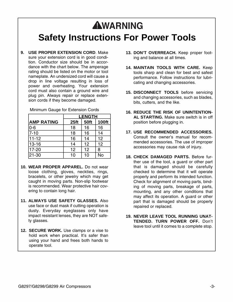
9. USE PROPER EXTENSION CORD. Makesure your extension cord is in good condi-tion. Conductor size should be in accor-dance with the chart below. The amperagerating should be listed on the motor or toolnameplate. An undersized cord will cause adrop in line voltage resulting in loss ofpower and overheating. Your extensioncord must also contain a ground wire andplug pin. Always repair or replace exten-sion cords if they become damaged.
Minimum Gauge for Extension Cords
10. WEAR PROPER APPAREL. Do not wearloose clothing, gloves, neckties, rings,bracelets, or other jewelry which may getcaught in moving parts. Non-slip footwearis recommended. Wear protective hair cov-ering to contain long hair.
11. ALWAYS USE SAFETY GLASSES. Alsouse face or dust mask if cutting operation isdusty. Everyday eyeglasses only haveimpact resistant lenses, they are NOT safe-ty glasses.
12. SECURE WORK. Use clamps or a vise tohold work when practical. It’s safer thanusing your hand and frees both hands tooperate tool.
LENGTHAMP RATING 25ft 50ft 100ft0-6 18 16 167-10 18 16 1411-12 16 14 1213-16 14 12 1217-20 12 12 821-30 10 10 No
Safety Instructions For Power Tools13. DON’T OVERREACH. Keep proper foot-
ing and balance at all times.
14. MAINTAIN TOOLS WITH CARE. Keeptools sharp and clean for best and safestperformance. Follow instructions for lubri-cating and changing accessories.
15. DISCONNECT TOOLS before servicingand changing accessories, such as blades,bits, cutters, and the like.
16. REDUCE THE RISK OF UNINTENTION-AL STARTING. Make sure switch is in offposition before plugging in.
17. USE RECOMMENDED ACCESSORIES.Consult the owner’s manual for recom-mended accessories. The use of improperaccessories may cause risk of injury.
18. CHECK DAMAGED PARTS. Before fur-ther use of the tool, a guard or other partthat is damaged should be carefullychecked to determine that it will operateproperly and perform its intended function.Check for alignment of moving parts, bind-ing of moving parts, breakage of parts,mounting, and any other conditions thatmay affect its operation. A guard or otherpart that is damaged should be properlyrepaired or replaced.
19. NEVER LEAVE TOOL RUNNING UNAT-TENDED. TURN POWER OFF. Don’tleave tool until it comes to a complete stop.
-4-
Additional Safety Instructions For AirCompressors
1. Operate the compressor in a well-ventilatedarea free of acids, vapor, explosive gasesand flammable or unstable materials.
2. Use compressor only with air, never usewith any other type of gas.
3. Never aim the air nozzle directly at yourselfor others. The air stream can be quite force-ful and can damage skin.
4. Do not pull on rubber hoses to move thecompressor.
5. Do not use compressed air for filling breath-ing or diving apparatus. Compressed airfrom this compressor cannot be used forpharmaceutical, food or health require-ments without further treatment.
6. Never transport the compressor under pres-sure. Always make sure the pressure in thestorage tanks has been released beforeloading or moving the air compressor.
7. Never attempt to adjust the pressure safetyvalve on the air tanks. This is preset to 150PSI.
Operating this equipment has the potentialto propel debris into the air which cancause eye injury. Always wear safety glass-es or goggles when operating equipment.Everyday glasses or reading glasses onlyhave impact resistant lenses, they are notsafety glasses. Be certain the safety glass-es you wear meet the appropriate stan-dards of the American National StandardsInstitute (ANSI).
Like all power tools, there is danger asso-ciated with the operation of air compres-sors. Accidents are frequently caused bylack of familiarity or failure to pay attention.Use this equipment with respect and cau-tion to lessen the possibility of operatorinjury. If normal safety precautions areoverlooked or ignored, serious personalinjury may occur.
No list of safety guidelines can be com-plete. Every shop environment is different.Always consider safety first, as it applies toyour individual working conditions. Usethis and other machinery with caution andrespect. Failure to do so could result inserious personal injury, damage to equip-

G8297/G8298/G8299 Air Compressors -5-
110V Operation
SECTION 2: CIRCUIT REQUIREMENTS
If you find it necessary to use an extension cordwith your compressor, make sure the cord israted Hard Service (grade S) or better. Refer tothe chart in the standard safety instructions todetermine the minimum gauge for the extensioncord. The extension cord must also contain aground wire and plug pin. Always repair orreplace extension cords when they become wornor damaged.
Extension Cords
Grounding
This equipment must be grounded. Verifythat any existing electrical outlet and circuityou intend to plug into is actually ground-ed. If it is not, it will be necessary to run aseparate 12 A.W.G. copper grounding wirefrom the outlet to a known ground. Underno circumstances should the grounding pinfrom any three-pronged plug be removed.Serious injury may occur.
In the event of an electrical short, groundingreduces the risk of electric shock by providing apath of least resistance to disperse electric cur-rent. These machines are equipped with powercords having an equipment-grounding conductor.See Figure 1. The outlet must be properlyinstalled and grounded in accordance with alllocal codes and ordinances.
This family of air compressors is wired for110/120V, single phase operation only. The chartbelow shows the maximum amperage draw andrecommended fusing level for each of themachines.
Figure 1. Grounded plug configuration.
G8297
G8298
G8299 (2 Motors)
2.0
2.5
2.52.0
11
17
1711
15
20
2015
Model AmperageHP
Max Fuse
It is generally best to operate a compressor on adedicated circuit, i.e. a circuit where there are noother electrical appliances plugged in. The dualmotors on the G8299 should be plugged into sep-arate circuits. The fuse requirements aboveassume the use of a circuit breaker or a slow-blow fuse. If an unusual load does not exist andthe compressor still breaks the circuit, contact aqualified electrician or our service department.
-6- G8297/G8298/G8299 Air Compressors
SECTION 3: INTRODUCTION
We are proud to offer the Grizzly ModelsG8297/8298/8299 Contractor Grade AirCompressors. These compressors are part of thegrowing Grizzly family of heavy-duty machineryfor the contractor and professional user. Whenused according to the guidelines set forth in thismanual, you can expect years of trouble-free,enjoyable operation and proof of Grizzly’s com-mitment to customer satisfaction.
These compressors are designed to suit theneeds of the professional contractor who requiresa reliable air source on the job site. The G8297 isa 2.0 HP unit with a 4.25 gallon tank capacity anddelivers 4.2 CFM@90 PSI. The G8298 is similarto the G8297 with the 2.5 HP motor which pro-vides 5.8 CFM. The dual motor 4.5 HP G8299delivers 10 CFM with a 9.0 gallon tank capacity.The G8299 is conveniently portable with a wheelbuilt into the tank system.
We are also pleased to provide this manual withyour new air compressor. It was written to guideyou through assembly, review safety considera-tions, and cover general operating procedures. Itrepresents our effort to produce the best docu-mentation possible. If you have any commentsregarding this manual, please write to us at theaddress below:
Grizzly Industrial, Inc.C/O Technical Documentation
P.O. Box 2069Bellingham, WA 98227-2069
Most importantly, we stand behind our machines.If you have any service questions or partsrequests, please call or write us at the locationlisted below.
Grizzly Industrial, Inc.1203 Lycoming Mall Circle
Muncy, PA 17756Phone: (570) 546-9663
Fax: (800) 438-5901E-Mail: [email protected] Site: http://www.grizzly.com
The specifications, drawings, and photographsillustrated in this manual represent the ModelsG8297/8298/8299 as supplied when the manualwas prepared. However, owing to Grizzly’s policyof continuous improvement, changes may bemade at any time with no obligation on the part ofGrizzly. Whenever possible, though, we sendmanual updates to all owners of a particular toolor machine. Should you receive one, we urge youto insert the new information with the old andkeep it for reference.
To operate this, or any power tool, safelyand efficiently, it is essential to become asfamiliar with its characteristics as possible.The time you invest before you begin to useyour air compressor will be time well spent.DO NOT operate this machine until you arecompletely familiar with the contents of thismanual. Make sure you read and under-stand all of the safety procedures. If you donot understand something, DO NOT operatethe machine.
Commentary

-7-
Unpacking
This air compressor is shipped from the manu-facturer in a carefully packed carton. If you dis-cover the machine is damaged after you’vesigned for delivery, and the truck and driver aregone, you will need to file a freight claim with thecarrier. Save the containers and all packing mate-rials for possible inspection by the carrier or itsagent. Without the packing materials, filing afreight claim can be difficult. If you need assis-tance determining whether you need to file afreight claim, or with the procedure to file one,please contact our Customer Service.
When taking the air compressor to a job site, themost important consideration is access to anadequate and properly fused power supply. Referto Section 2: Circuit Requirements for the needsfor your particular compressor.
Also make sure the compressor is not operatingin an environment where there are any explosive,flammable or caustic fumes or gases. A clear andwell-ventilated area is best for its safe operation.
Place the compressor on a solid and level sur-face. Make sure that the hoses you attach to sup-ply your pneumatic device will be unrestricted inmovement and not subject to being run over byvehicles or punctured by any other sharp objectsin the area.
And since air compressors are often used for asustained period of time, sometimes in restrictedareas, it is also best to wear ear protection toavoid the long-term exposure to the sound of theelectric motor and piston.
NOTICEThe machine should always be run in thepositions shown on the cover of this manu-al. Never run the G8299 when it is standingupright on its wheel and support frame.Also never continue to operate the machineif it has fallen over on its side. The motorwill not receive adequate oil flow in thesepositions, and continued operation can

-8-
Before using your Grizzly Air Compressor, followthese steps before the first use:
1. Remove all packing materials and the pro-tective plastic plugs from the cylinder headand oil plug. Do not remove the yellow capunderneath the black plastic cover of thepressure switch housing.
2. Screw the air filter(s) into the cylinderhead(s).
3. Place the oil dipstick into the opening of thecasing and check the oil level in the motorcrankcase. See Figure 2. Each motorrequires approximately 100 cc or 3.5 fluidounces of compressor oil (ISO 100 or SAE30W viscosity, non-detergent). Make cer-tain the oil is at the full indicator level on thedipstick.
Operating this equipment has the potentialto propel debris into the air which cancause eye injury. Always wear safety glass-es or goggles when operating equipment.Everyday glasses or reading glasses onlyhave impact resistant lenses, they are notsafety glasses. Be certain the safety glass-es you wear meet the appropriate stan-dards of the American National StandardsInstitute (ANSI).
Operating this equipment has the potentialfor hearing damage to occur, especially ifoperated for a long period of time. UseANSI (American National StandardsInstitute) approved ear muff or ear plugswhen using this equipment. Always wearproper hearing protection, cotton balls ortissue paper in the ear canal do not provideadequate noise reduction.
Fig 2. Oil sump and dipstick.
4. Make sure drain valve(s) on the air tanks isclosed.
5. Make sure the power switch is in the OFFposition, fully pushed in. Connect the powercord(s) to a properly protected powersource.
NOTICEThe machine should never be run without afull oil reservoir. The oil provides lubrica-tion to the cylinder rings which deliver thecompressed air. Severe damage to theinternal parts can occur if there is not ade-quate oil flow. Check the oil level frequent-ly, and change the oil on a regular sched-
G8297/G8298/G8299 Air Compressors -9-
SECTION 4: OPERATIONS
The pump produces compressed air which goesinto the air tanks through the delivery pipe andthe check valve. When the air pressure arrives atthe factory pre-set level of 135 PSI, the pressureswitch shuts off the electrical current to the axialelectric pump. At the time it shuts off, it dis-charges the air held in the pump cylinder to thedelivery pipe. This allows the pump to be depres-surized so it can easily restart. When the pres-sure in the air tanks falls below the minimum fac-tory set pressure of 105 PSI, the pump cyclesagain to build the pressure back up. The pressureswitch is supplied with a discharge valve withdelayed closing, which reduces the strain on thepump and the motor during startup.
The compressor is operating correctly when thereis a bleed of air every time the motor is switchedoff. You will notice an audible air discharge eachtime the pump motor stops. On these compres-sors, the pump will cycle first to minimize theamperage draw and will bleed off air through thecold-start valve. The valve will stay open untilapproximately 20 PSI is reached in the air tanksat which time it closes to allow full pressurizationof the tanks.
For the G8299 with the dual motors, both motorscan be started simultaneously for rapid pressur-ization. As with the G8298, the 2.5 HP pump is fit-ted with a cold-start valve which will stay openuntil approximately 20 PSI is reached in thetanks. This will allow the compressor to lubricateproperly without straining the motor and pump.
Depending on the volume of the air usage, it isoften adequate to recharge the system duringoperation using only the 2 HP pump takingadvantage of its lower RPM and quieter opera-tion.
General
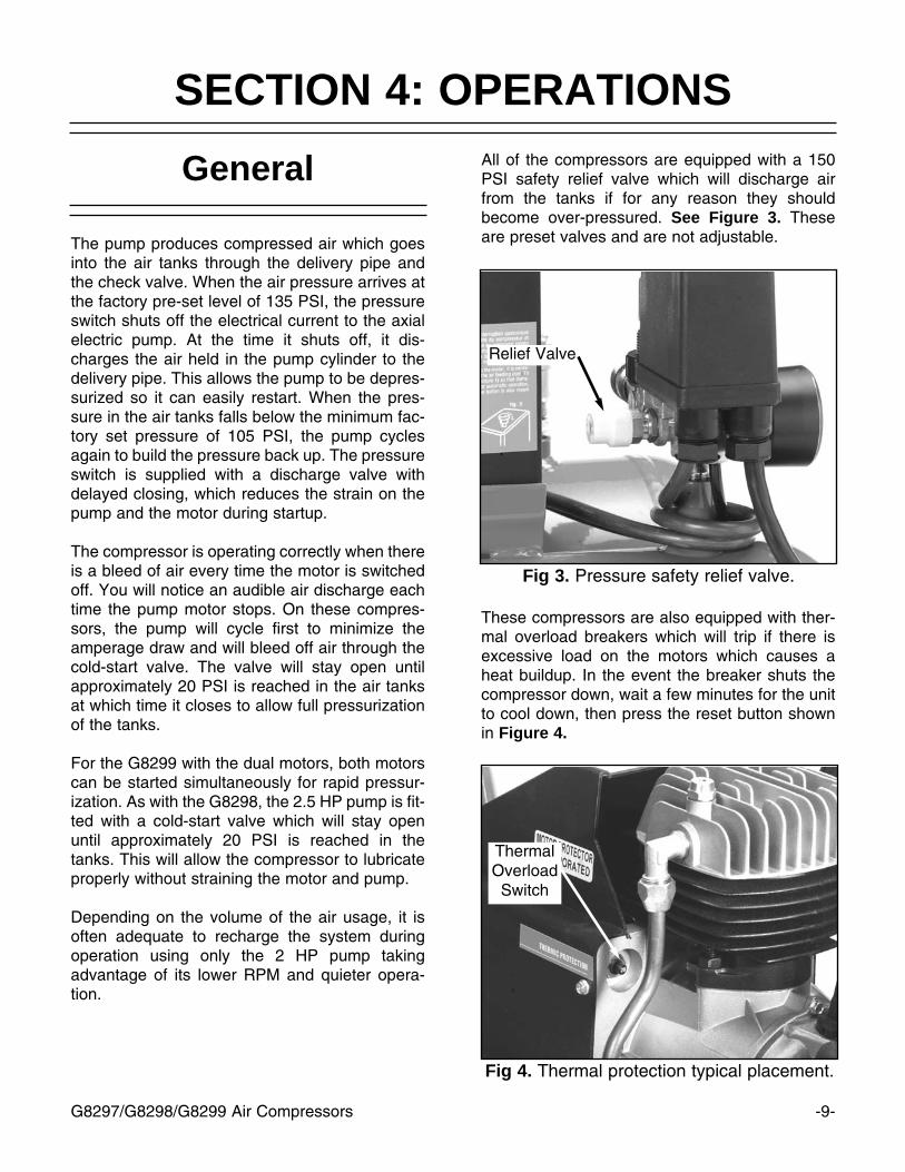
Fig 3. Pressure safety relief valve.
All of the compressors are equipped with a 150PSI safety relief valve which will discharge airfrom the tanks if for any reason they shouldbecome over-pressured. See Figure 3. Theseare preset valves and are not adjustable.
Relief Valve
Fig 4. Thermal protection typical placement.
ThermalOverloadSwitch
These compressors are also equipped with ther-mal overload breakers which will trip if there isexcessive load on the motors which causes aheat buildup. In the event the breaker shuts thecompressor down, wait a few minutes for the unitto cool down, then press the reset button shownin Figure 4.

-10- G8297/G8298/G8299 Air Compressors
After the compressor has fully pressurized thetanks, turn the red knob on the pressure regula-tor (See Figure 6) to set the pressure needed forthe air tool you will be using. Consult the manualwhich accompanied your air tool to determinewhat pressure setting is required for optimal oper-ation. The gauge on the regulator will indicate thepressure which will be delivered through the airline.
Pressure Regulator
Make sure the compressor switch is in the OFFposition (the red button on top of the control boxshould be in the fully depressed position, seeFigure 5) before connecting to the power supply.Close the drain cock on the tanks. Pull the switchto the ON position.
Starting
Fig 5. G8299 starting switches and gauge.
Check the tank pressure gauge to see that thetank pressure gets up to approximately 120-130PSI.
TankGauge
On/OffSwitches
Fig 6. Pressure regulator and gauge.
Always wear safety glasses and useextreme caution when working aroundcompressed air. The force of the air streamcan cause small bits of debris to becomeairborne and cause potential injury to theeyes or other parts of the body. Never letthe full force of the air stream come indirect contact with the skin as it can causeabrasions or bruising.

G8297/G8298/G8299 Air Compressors -11-
Make sure the compressor model you use hassufficient cubic feet per minute (CFM) output forthe air tool you plan to connect. Most air tools willhave an air requirement stated in terms of a spe-cific CFM at a specific pressure (PSI). Most com-mon is a rating at 90 PSI. Consult the chart belowto determine the output of your compressormodel.
Connecting Tools Notes
G8297
G8298
G8299
2.0
2.5
4.5
4.2
5.8
10
4.25 gal
4.25 gal
9.0 gal
Model HP CFM@ 90 PSI
TankCap.
The compressor should put out a higher CFMthan the tool requires. If connecting multiple toolswhich will be used simultaneously, then the CFMfor each tool should be added together and com-pared to the compressor output value.
Consideration should also be given to the type ofusage. A nailer or staple gun uses air in shortbursts and it is easier for the compressor to main-tain pressure. A paint sprayer or grinder tends touse a more continuous stream of air as thesetools are run for longer time periods. It is alwaysbetter to oversize a compressor to allow for vari-ation in the type of usage and the number of toolsto be powered. Air tools being operated withinsufficient air volume will not perform their func-tion satisfactorily.
Connect the tool using a good quality air line withan adequate length to reach from the compressorto the point of use. Quick-connect couplers are agood option for fast and sure connection of toolsand air hoses. Make certain the air hose will notbe placed in a position where it can become con-stricted or cut by a sharp object. Having a hoserun over by heavy vehicles may not cause animmediate leak, but it will shorten the life of thehose.

G8297/G8298/G8299 Air Compressors
SECTION 5: MAINTENANCE
Regular periodic maintenance on your AirCompressor will ensure its optimum perfor-mance. Make a habit of inspecting your compres-sor each time you use it. Check the followingitems:
1. Check oil level. See Figure 7.
Each Use
Fig 7. Checking oil level with dipstick.
-12-
Fig 8. Typical location of drain cocks.
2. Drain tanks of any condensation by open-ing the drain cocks on the bottom of bothtanks. See Figure 8. Depending upon theamount of use and the weather conditions,a certain amount of condensed water maybe released. For longevity of the compres-sor seals and the air tools you connect, it isbest to keep the tanks free of water. Thetanks are best drained if the drain cocks areopened when the system is pressurized.Once water has stopped coming out, youcan close the drain cocks.
3. Clean off cylinder head cooling fins of anydirt which might hamper air flow.
4. Check for worn or damaged cords andplugs.
5. Check for any other condition that couldhamper the safe operation of this machine.
Always wear safety glasses and useextreme caution when working aroundcompressed air. The force of the air streamcan cause small bits of debris to becomeairborne and cause potential injury to theeyes or other parts of the body. Never letthe full force of the air stream come indirect contact with the skin as it can causeabrasions or bruising.
G8297/G8298/G8299 Air Compressors -13-
Weekly
Every 300 Hours
If the compressor is used on a regular daily basis,perform the following checks each week:
1. Rinse the air filter foam element in water.
2. Check for loose bolts or fittings.
After every 300 hours or 3 months of regularoperation, perform the following maintenanceitems:
1. Change compressor motor oil.
2. Rinse the air filter foam element in water.
3. Check for air leaks and correct as needed.
4. Clean cylinder head fins for proper cooling.
5. Check for loose bolts or fittings.
After First 50 Hours
After the first 50 working hours, or 30 days,whichever comes first, replace the oil in themotor with compressor oil (use ISO 100 or SAE30W viscosity, non-detergent type).
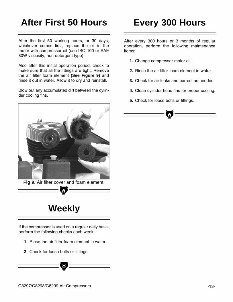
Also after this initial operation period, check tomake sure that all the fittings are tight. Removethe air filter foam element (See Figure 9) andrinse it out in water. Allow it to dry and reinstall.
Blow out any accumulated dirt between the cylin-der cooling fins.
Fig 9. Air filter cover and foam element.
Do not remove the pressure switch coverwith the machine plugged in to power.When the cover is off, the electrical con-nections are uncovered and can be asource of electrical shock. Make the adjust-ments progressively until the desired levelis reached, and disconnect from powereach time you turn the adjusting nut.Serious personal injury can occur.
-14- G8297/G8298/G8299 Air Compressors
Pressure LimitAdjustment
The compressor is delivered with pressure switchsettings which turn the compressor pump offwhen it reaches a tank pressure of 135 PSI, andturn it back on when it reaches 105 PSI. Normallythese settings should not require any adjustment.
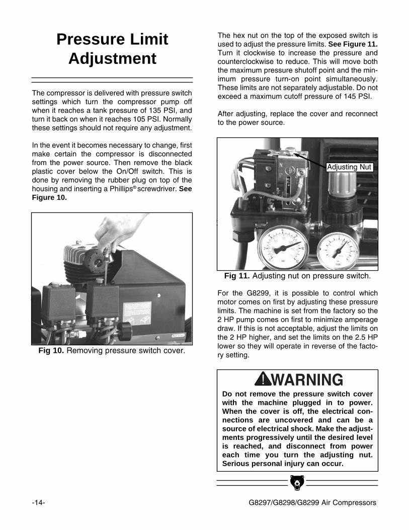
In the event it becomes necessary to change, firstmake certain the compressor is disconnectedfrom the power source. Then remove the blackplastic cover below the On/Off switch. This isdone by removing the rubber plug on top of thehousing and inserting a Phillips® screwdriver. SeeFigure 10.
Fig 10. Removing pressure switch cover.
The hex nut on the top of the exposed switch isused to adjust the pressure limits. See Figure 11.Turn it clockwise to increase the pressure andcounterclockwise to reduce. This will move boththe maximum pressure shutoff point and the min-imum pressure turn-on point simultaneously.These limits are not separately adjustable. Do notexceed a maximum cutoff pressure of 145 PSI.
After adjusting, replace the cover and reconnectto the power source.
Fig 11. Adjusting nut on pressure switch.
Adjusting Nut
For the G8299, it is possible to control whichmotor comes on first by adjusting these pressurelimits. The machine is set from the factory so the2 HP pump comes on first to minimize amperagedraw. If this is not acceptable, adjust the limits onthe 2 HP higher, and set the limits on the 2.5 HPlower so they will operate in reverse of the facto-ry setting.
G8297/G8298/G8299 Air Compressors -15-
The following pages contain general machinedata, parts diagrams/lists, troubleshooting guideand Warranty/Return information for your ModelG8297/8298/8299 Air Compressor.
If you need parts or help in assembling yourmachine, or if you need operational information,we encourage you to call our ServiceDepartment. Our trained service technicians willbe glad to help you.
If you have comments dealing specifically withthis manual, please write to our Bellingham,Washington location using the address in Section3 Introduction. The specifications, drawings, andphotographs illustrated in this manual representthe Model G8297/8298/8299 Air Compressor assupplied when the manual was prepared.However, due to Grizzly’s policy of continuousimprovement, changes may be made at any timewith no obligation on the part of Grizzly.Whenever possible, though, we send manualupdates to all owners of a particular tool ormachine. Should you receive one, add the newinformation to this manual and keep it for refer-ence.
We have included some important safety mea-sures that are essential to this machine’s opera-tion. While most safety measures are generallyuniversal, Grizzly reminds you that each work-shop is different and safety rules should be con-sidered as they apply to your specific situation.
We recommend you keep a copy of our currentcatalog for complete information regardingGrizzly's warranty and return policy. If you needadditional technical information relating to thismachine, or if you need general assistance orreplacement parts, please contact the ServiceDepartment listed in Section 3: or Introduction.
Additional information sources are necessary torealize the full potential of this machine. Tradejournals, woodworking magazines, and your locallibrary are good places to start.
SECTION 6: CLOSURE
The Model G8297/8298/8299 Air Compressorsare specifically designed for air tool operation.DO NOT MODIFY AND/OR USE THISMACHINE FOR ANY OTHER PURPOSE.Modifications or improper use of this toolwill void the warranty. If you are confusedabout any aspect of this machine, DO NOT useit until you have answered all your questions.Serious personal injury may occur.
Like all power tools, there is danger asso-ciated with operating this equipment.Accidents are frequently caused by lack offamiliarity or failure to pay attention. Usethis tool with respect and caution to lessenthe possibility of operator injury. If normalsafety precautions are overlooked orignored, serious personal injury mayoccur.Operating this equipment has the potential
for flying debris to cause eye injury.Always wear safety glasses or goggleswhen operating equipment. Everydayglasses or reading glasses only haveimpact resistant lenses, they are not safetyglasses. Be certain the safety glasses youwear meet the appropriate standards of theAmerican National Standards Institute(ANSI).
-16- G8297/G8298/G8299 Air Compressors
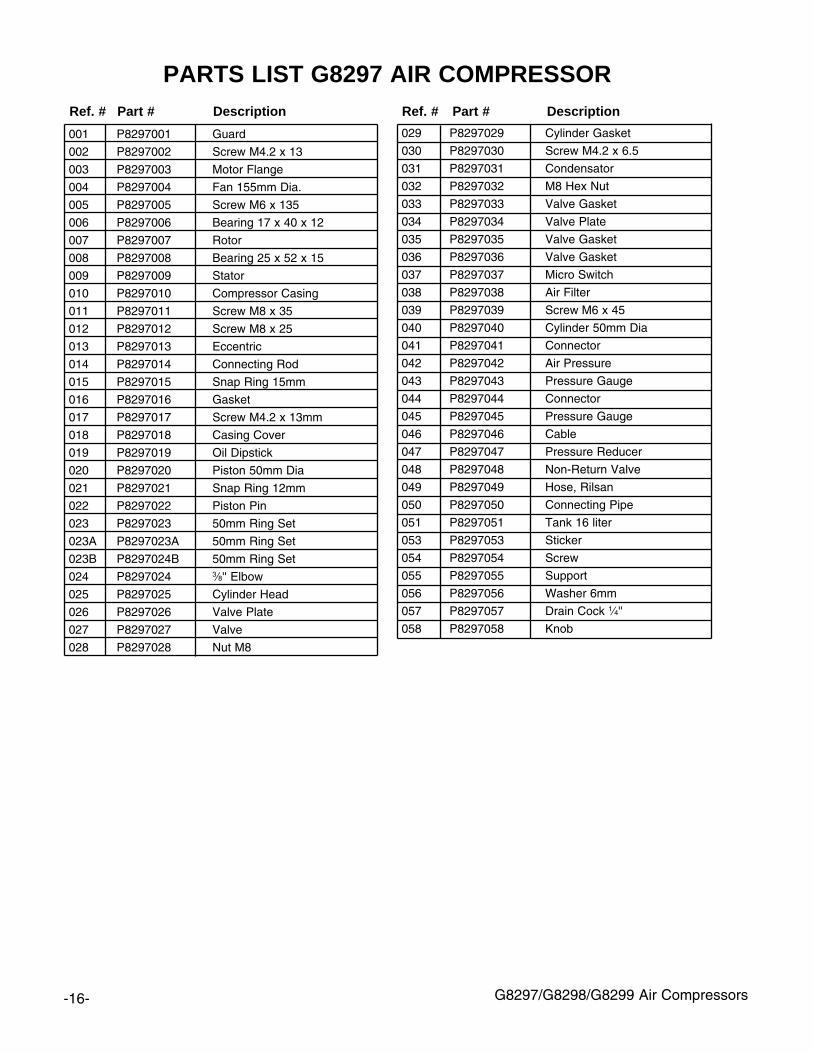
001 P8297001 Guard
002 P8297002 Screw M4.2 x 13
003 P8297003 Motor Flange
004 P8297004 Fan 155mm Dia.
005 P8297005 Screw M6 x 135
006 P8297006 Bearing 17 x 40 x 12
007 P8297007 Rotor
008 P8297008 Bearing 25 x 52 x 15
009 P8297009 Stator
010 P8297010 Compressor Casing
011 P8297011 Screw M8 x 35
012 P8297012 Screw M8 x 25
013 P8297013 Eccentric
014 P8297014 Connecting Rod
015 P8297015 Snap Ring 15mm
016 P8297016 Gasket
017 P8297017 Screw M4.2 x 13mm
018 P8297018 Casing Cover
019 P8297019 Oil Dipstick
020 P8297020 Piston 50mm Dia
021 P8297021 Snap Ring 12mm
022 P8297022 Piston Pin
023 P8297023 50mm Ring Set
023A P8297023A 50mm Ring Set
023B P8297024B 50mm Ring Set
024 P8297024 3⁄8'' Elbow
025 P8297025 Cylinder Head
026 P8297026 Valve Plate
027 P8297027 Valve
028 P8297028 Nut M8
029 P8297029 Cylinder Gasket
030 P8297030 Screw M4.2 x 6.5
031 P8297031 Condensator
032 P8297032 M8 Hex Nut
033 P8297033 Valve Gasket
034 P8297034 Valve Plate
035 P8297035 Valve Gasket
036 P8297036 Valve Gasket
037 P8297037 Micro Switch
038 P8297038 Air Filter
039 P8297039 Screw M6 x 45
040 P8297040 Cylinder 50mm Dia
041 P8297041 Connector
042 P8297042 Air Pressure
043 P8297043 Pressure Gauge
044 P8297044 Connector
045 P8297045 Pressure Gauge
046 P8297046 Cable
047 P8297047 Pressure Reducer
048 P8297048 Non-Return Valve
049 P8297049 Hose, Rilsan
050 P8297050 Connecting Pipe
051 P8297051 Tank 16 liter
053 P8297053 Sticker
054 P8297054 Screw
055 P8297055 Support
056 P8297056 Washer 6mm
057 P8297057 Drain Cock 1⁄4''
058 P8297058 Knob
Ref. # Part # Description Ref. # Part # Description
PARTS LIST G8297 AIR COMPRESSOR

G8297/G8298/G8299 Air Compressors -17-

-18- G8297/G8298/G8299 Air Compressors
001 P8298001 Guard
002 P8298002 Screw M4.2 x 13
003 P8298003 Motor Flange
004 P8298004 Fan 155mm Dia.
005 P8298005 Screw M6 x 135
006 P8298006 Bearing 17 x 40 x 12
007 P8298007 Rotor
008 P8298008 Bearing 25 x 52 x 15
009 P8298009 Stator
010 P8298010 Compressor Casing
011 P8298011 Screw M8 x 35
012 P8298012 Screw M8 x 25
013 P8298013 Eccentric
014 P8298014 Connecting Rod
015 P8298015 Snap Ring 15mm
016 P8298016 Gasket
017 P8298017 Screw M4.2 x 13mm
018 P8298018 Casing Cover
019 P8298019 Oil Dipstick
020 P8298020 Piston
021 P8298021 Snap Ring 12mm
022 P8298022 Piston Pin
023 P8298023 Ring Set
023A P8298023A Ring Set
023B P8298024B Ring Set
024 P8298024 3⁄8'' Elbow
025 P8298025 Cylinder Head
026 P8298026 Valve Plate
027 P8298027 Valve
028 P8298028 Nut M8
029 P8298029 Cylinder Gasket
030 P8298030 Screw M4.2 x 6.5
031 P8298031 Condensator
032 P8298032 M8 Hex Nut
033 P8298033 Valve Gasket
034 P8298034 Valve Plate
035 P8298035 Valve Gasket
036 P8298036 Valve Gasket
037 P8298037 Micro Switch
038 P8298038 Air Filter
039 P8298039 Screw M6 x 45
040 P8298040 Cylinder
041 P8298041 Drain Cock 1⁄4''
042 P8298042 Tank
043 P8298043 Knob
044 P8298044 Connector
045 P8298045 Valve 1⁄4''
046 P8298046 Non-Return Valve
047 P8298047 Connecting Pipe
049 P8298049 Screw
050 P8298050 Hex Nut M6
051 P8298051 Washer 6mm
052 P8298052 Support
053 P8298053 Screw M6 x 30
054 P8298054 Cable
055 P8298055 Pressure Gauge
056 P8298056 Pressure Reducer
057 P8298057 Hose, Rilsan
058 P8298058 Connector
059 P8297059 Air Pressure
060 P8297060 Pressure Gauge
061 P8297060 Connector
Ref. # Part # Description Ref. # Part # Description
PARTS LIST G8298 AIR COMPRESSOR
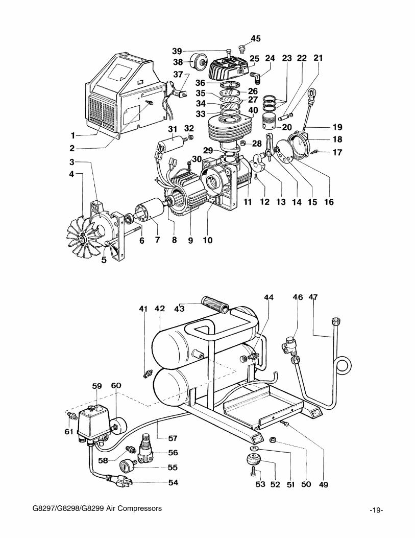
G8297/G8298/G8299 Air Compressors -19-

-20- G8297/G8298/G8299 Air Compressors
041 P8299041 Air Pressure
042 P8299042 Connecting Pipe
043 P8299043 Non-return valve
044 P8299044 Knob 22mm
046 P8299046 Tank Assembly
047 P8299047 Washer 8mm
048 P8299048 Support
049 P8299049 Hex Nut M8
050 P8299050 Wheel
051 P8299051 Pipe
052 P8299052 Hex Nut M6
053 P8299053 Screw
054 P8299054 Pressure Reducer
055 P8299055 Pressure Gauge
056 P8299056 Nipple 1⁄4''
057 P8299057 Air Pressure
058 P8299058 Cable
059 P8299059 Valve
060 P8299060 Drain Cock 1⁄4''
Ref. # Part # Description
PARTS LIST G8299 AIR COMPRESSORThe G8299 utilizes the 2 HP motor from the G8297 and the 2.5 HP motor from the G8298. The partnumbers are as referenced for those components on the previous pages.
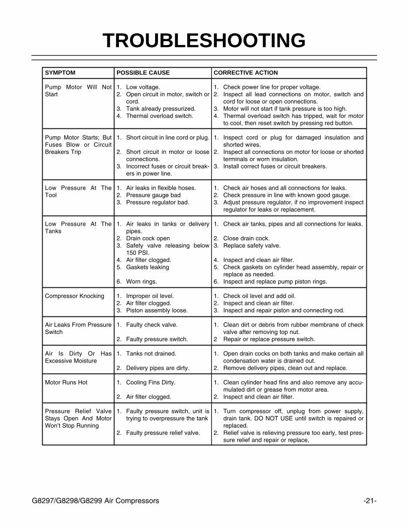
G8297/G8298/G8299 Air Compressors -21-
SYMPTOM
Pump Motor Will NotStart
Pump Motor Starts; ButFuses Blow or CircuitBreakers Trip
Low Pressure At TheTool
Low Pressure At TheTanks
Compressor Knocking
Air Leaks From PressureSwitch
Air Is Dirty Or HasExcessive Moisture
Motor Runs Hot
Pressure Relief ValveStays Open And MotorWon’t Stop Running
POSSIBLE CAUSE
1. Low voltage. 2. Open circuit in motor, switch or
cord.3. Tank already pressurized.4. Thermal overload switch.
1. Short circuit in line cord or plug.
2. Short circuit in motor or looseconnections.
3. Incorrect fuses or circuit break-ers in power line.
1. Air leaks in flexible hoses.2. Pressure gauge bad3. Pressure regulator bad.
1. Air leaks in tanks or deliverypipes.
2. Drain cock open3. Safety valve releasing below
150 PSI.4. Air filter clogged.5. Gaskets leaking
6. Worn rings.
1. Improper oil level.2. Air filter clogged.3. Piston assembly loose.
1. Faulty check valve.
2. Faulty pressure switch.
1. Tanks not drained.
2. Delivery pipes are dirty.
1. Cooling Fins Dirty.
2. Air filter clogged.
1. Faulty pressure switch, unit istrying to overpressure the tank
2. Faulty pressure relief valve.
CORRECTIVE ACTION
1. Check power line for proper voltage.2. Inspect all lead connections on motor, switch and
cord for loose or open connections.3. Motor will not start if tank pressure is too high.4. Thermal overload switch has tripped, wait for motor
to cool, then reset switch by pressing red button.
1. Inspect cord or plug for damaged insulation andshorted wires.
2. Inspect all connections on motor for loose or shortedterminals or worn insulation.
3. Install correct fuses or circuit breakers.
1. Check air hoses and all connections for leaks.2. Check pressure in line with known good gauge.3. Adjust pressure regulator, if no improvement inspect
regulator for leaks or replacement.
1. Check air tanks, pipes and all connections for leaks.
2. Close drain cock.3. Replace safety valve.
4. Inspect and clean air filter.5. Check gaskets on cylinder head assembly, repair or
replace as needed.6. Inspect and replace pump piston rings.
1. Check oil level and add oil.2. Inspect and clean air filter.3. Inspect and repair piston and connecting rod.
1. Clean dirt or debris from rubber membrane of checkvalve after removing top nut.
2 Repair or replace pressure switch.
1. Open drain cocks on both tanks and make certain allcondensation water is drained out.
2. Remove delivery pipes, clean out and replace.
1. Clean cylinder head fins and also remove any accu-mulated dirt or grease from motor area.
2. Inspect and clean air filter.
1. Turn compressor off, unplug from power supply,drain tank. DO NOT USE until switch is repaired orreplaced.
2. Relief valve is relieving pressure too early, test pres-sure relief and repair or replace,
TROUBLESHOOTING

-22- G8297/G8298/G8299 Air Compressors
Grizzly Industrial, Inc. warrants every product it sells for a period of 1 year to the original purchaser fromthe date of purchase. This warranty does not apply to defects due directly or indirectly to misuse, abuse,negligence, accidents, repairs or alterations or lack of maintenance. This is Grizzly’s sole written warrantyand any and all warranties that may be implied by law, including any merchantability or fitness, for any par-ticular purpose, are hereby limited to the duration of this written warranty. We do not warrant or representthat the merchandise complies with the provisions of any law or acts unless the manufacturer so warrants.In no event shall Grizzly’s liability under this warranty exceed the purchase price paid for the product andany legal actions brought against Grizzly shall be tried in the State of Washington, County of Whatcom.
We shall in no event be liable for death, injuries to persons or property or for incidental, contingent, spe-cial, or consequential damages arising from the use of our products.
To take advantage of this warranty, contact us by mail or phone and give us all the details. We will thenissue you a “Return Number’’, which must be clearly posted on the outside as well as the inside of the car-ton. We will not accept any item back without this number. Proof of purchase must accompany the mer-chandise.
The manufacturers reserve the right to change specifications at any time because they constantly strive toachieve better quality equipment. We make every effort to ensure that our products meet high quality anddurability standards and we hope you never need to use this warranty.
Please feel free to write or call us if you have any questions about the machine or the manual.
Thank you again for your business and continued support. We hope to serve you again soon.
WARRANTY AND RETURNS

10. Which benchtop tools do you own? Check all that apply.
___1" x 42" Belt Sander ___6" - 8" Grinder___5" - 8" Drill Press ___Mini Lathe___8" Table Saw ___10" - 12" Thickness Planer ___8" - 10" Bandsaw ___Scroll Saw___Disc/Belt Sander ___Spindle/Belt Sander___Mini Jointer
___Other__________________________________________________
11. How many of the machines checked above are Grizzly? ____________
12. Which portable/hand held power tools do you own? Check all that apply.
___Belt Sander ___Orbital Sander___Biscuit Joiner ___Palm Sander___Circular Saw ___Portable Planer___Detail Sander ___Saber Saw___Drill/Driver ___Reciprocating Saw___Miter Saw ___Router
___Other__________________________________________________
13. What machines/supplies would you like Grizzly Industrial to carry?
___12" Table Saw ___Radial Arm Saw___12" Jointer ___Panel Saw___Combination Planer/Jointer ___Brass Hardware___Paint & Finishing Supplies ___Lumber___Contractor’s Supplies
___Other__________________________________________________
14. What new accessories would you like Grizzly Industrial to carry?
___Builders Hardware ___Hand Tools___Fasteners ___Wood Components
___Other__________________________________________________
15. What other companies do you purchase your tools and supplies from?
__________________________________________________________
__________________________________________________________
16. Do you think your purchase represents good value?
___Yes ___No
17. Would you recommend Grizzly Imports to a friend?
___Yes ___No
18. Would you allow us to use your name as a reference for Grizzly customersin your area? Note: We never use names more than three times.
___Yes ___No
19. Comments:_________________________________________________
__________________________________________________________
__________________________________________________________
__________________________________________________________
__________________________________________________________
1. How did you learn about us?
___Advertisement ___Friend___Catalog ___Card Deck___World Wide Web
___Other__________________________________________________
2. Which of the following magazines do you subscribe to.
___American Woodworker ___Practical Homeowner___Cabinetmaker ___Shop Notes___Family Handyman ___Today’s Homeowner___Fine Homebuilding ___WOOD___Fine Woodworking ___Wooden Boat___Home Handyman ___Woodshop News___Journal of Light Construction ___Woodsmith___Old House Journal ___Woodwork___Popular Mechanics ___Woodworker___Popular Science ___Woodworker’s Journal___Popular Woodworking ___Workbench
___Other__________________________________________________
3. Which of the following woodworking/remodeling shows do you watch?
___Backyard America ___The New Yankee Workshop___Home Time ___This Old House___The American Woodworker ___Woodwright’s Shop
___Other__________________________________________________
4. What is your annual household income?
___$20,000-$29,999 ___$60,000-$69,999___$30,000-$39,999 ___$70,000-$79,999___$40,000-$49,999 ___$80,000-$89,999___$50,000-$59,999 ___$90,000 +
5. What is your age group?
___20-29 ___50-59___30-39 ___60-69___40-49 ___70 +
6. How long have you been a woodworker?
___0 - 2 Years ___8 - 20 Years___2 - 8 Years ___20+ Years
7. How would you rank your woodworking skills?
___Simple ___Advanced___Intermediate ___Master Craftsman
8. What stationary woodworking tools do you own? Check all that apply.
___Air Compressor ___Panel Saw___Band Saw ___Planer___Drill Press ___Power Feeder___Drum Sander ___Radial Arm Saw___Dust Collector ___Shaper___Horizontal Boring Machine ___Spindle Sander___Jointer ___Table Saw___Lathe ___Vacuum Veneer Press___Mortiser ___Wide Belt Sander
___Other__________________________________________________
9. How many of your woodworking machines are Grizzly? _____________
Name ____________________________________________________________________________________Street ____________________________________________________________________________________City ______________________________________________________________State________Zip_________Phone Number_______________________E-Mail_______________________FAX________________________MODEL # ______________________________Order #______________________________________________
The following information is given on a voluntary basis. It will be used for marketing purposes to help us develop better products and services. Ofcourse, all information is strictly confidential.
WARRANTY CARD

FOLD ALONG DOTTED LINE
FOLD ALONG DOTTED LINE
GRIZZLY INDUSTRIAL, INC.P.O. BOX 2069BELLINGHAM, WA 98227-2069
TAPE ALONG EDGES--PLEASE DO NOT STAPLE
Name_______________________________
Street_______________________________
City______________State______Zip______
Send a Grizzly Catalog to a friend: