Embed Size (px)
Citation preview
CONTRACTOR INSTALLATION INSTRUCTION
FOR
ELECTRICAL SUB-METERING
REVISION V1.5
SEPTEMBER 2020

DEPARTMENT OF DEFENCE CONTRACTOR INSTALLATION INSTRUCTION – ELECTRICAL SUB-METERING
DOCUMENT STATUS
Version No. Issue Date Amendment Details Amended by
0 November 2015
Draft version issued for inputs Defence
1.0 December 2016
Final version issued for upload to DEQMS. This document supersedes the ‘Electrical Sub-metering Manual for New Construction’ and the ‘Electrical Sub-metering Manual for Retrofits’.
Defence
1.1 March 2017 Contact details of NSP Program Manager changed and security requirements added
MWH
1.2 June 2017 Contact details of NSP Program Manager changed
Stantec
1.3 March 2018 Contact details of DEEERMS Assistant Director and of NSP Program Manager changed
Stantec
1.4 October 2019 Contact details of NSP Program Manager changed and 3G requirements changed to 4G where available.
Stantec
1.5 September 2020
Added requirements for remote sites Stantec
1.6 July 2021 Change of NSP Provider Defence
DEPARTMENT OF DEFENCE CONTRACTOR INSTALLATION INSTRUCTION – ELECTRICAL SUB-METERING
TABLE OF CONTENTS
1. PURPOSE ........................................................................................................................................... 1 2. LEGAL STATEMENT .......................................................................................................................... 1 3. NATIONAL SUB-METER PROGRAM DOCUMENTATION ..................................................................... 1 4. RELEVANT CONTACTS ..................................................................................................................... 2 SECTION 1 - PRE-SITE PLANNING AND PROCUREMENT ...................................................... 4 SECTION 2 – SITE INSTALLATION ............................................................................................... 7 SECTION 3 - COMMISSIONING & SIGN OFF ............................................................................ 10 APPENDIX A – SUB-METERING CHECKLIST .......................................................................... 13 APPENDIX B – STANDARDS AND LEGISLATION .................................................................... 14 1. STANDARDS AND CODES ................................................................................................................ 14 2. RELEVANT STATE BASED AGENCIES .............................................................................................. 14 APPENDIX C – ELECTRONIC FORM EXAMPLES ................................................................... 15 1. NEW METER FORM ......................................................................................................................... 15 2. METER HIERARCHY FORM ............................................................................................................. 16

DEPARTMENT OF DEFENCE CONTRACTOR INSTALLATION INSTRUCTION – ELECTRICAL SUB-METERING
GLOSSARY OF TERMS AND ABBREVIATIONS
AS Australian Standard
BMS Building Management System
CB Circuit Breaker
CT Current Transformer
DB Distribution Board
DERMS Directorate of Environmental Resource Management & Sustainability
DPM Defence Project Manager
Defence Commonwealth Department of Defence
Detailed
metering
schedule
Detailed instructions on appropriate sub-metering points at an existing Defence site,
as previously scoped up by the Defence Representative.
EEGO Energy Efficiency in Government Operations (Policy 2006, second edition 2007)
EMC Electromagnetic Compatibility
EMOS Estate Maintenance and Operations Services
ESAA Energy Supply Association Australia
GPRS General Packet Radio Service
GSM Global Systems for Mobile Communications
HRC High Rupture Capacity (fuse, usually filled with sand or similar)
HVAC Heating, Ventilating and Air-Conditioning
IP Internet Protocol
LCD Liquid Crystal Display
LED Light Emitting Diode
LVCT Low Voltage Current Transformer
MDA Meter Data Agent
MIEE Manual of Infrastructure Engineering – Electrical
MSB Main Switch Board
MSSB Mechanical Services Switch Board
MTB Meter Test Block
NCC National Construction Code
NMI National Meter Identifier
NSP National Sub-meter Program
NZS New Zealand Standard
RESO Regional Energy/Environmental and Sustainability Manager
RDMS Resource Data Management System
RMR Remote Meter Read
SIM Subscriber Identity Module
SIR Service Installation Rules
TWS Transformer Winding Services
VT Voltage Transformer
WHS Work Health and Safety

DEPARTMENT OF DEFENCE CONTRACTOR INSTALLATION INSTRUCTION – ELECTRICAL SUB-METERING
- 1 -
PRELIMINARIES
1. Purpose
The purpose of this document is to provide information and guidance to sub-metering contractors during
the planning, procurement, installation and commissioning for new and replacement electrical sub-
meters for the Commonwealth Department of Defence (‘Defence’) under the National Sub-meter
Program (NSP).
This document refers to the commissioning of sub-meters into Defence’s Resource Data Management
System (RDMS).
2. Legal Statement
Whilst this manual contains material relevant to electricity industry legislation, Codes of Practice and
Standards, it is not intended to provide legal advice on how contractors can meet their own statutory
obligations or comply with Legislation, Codes of Practice or industry Standards such as the SAA Wiring
Rules AS/NZS 3000.
This document provides guidelines for sub-meter installation and connection of these energy meters
and associated wireless telemetry. Where departures from these guidelines may be necessary, prior
consultation with Defence will be required.
Appendix B lists all relevant legislation, standards and codes that shall be adhered to as part of the
procurement, installation and commissioning of the sub-meters.
Note:
a) If there is any inconsistency between these guidelines and the relevant State, Territory and
Commonwealth legislation, then the hierarchy shall be that the requirements of the relevant
legislation shall prevail in the first instance.
b) This instruction is focusing on Delivery Phase only and you should always refer to Smart
Infrastructure Handbook: Planning, Design and Construction for overall program objective and
requirements
3. National Sub-meter Program Documentation
The relevant documentation associated with each project phase for the planning, design,
implementation and ongoing maintenance of sub-metering across the Defence estate are all available
on DEQMS
(https://www.defence.gov.au/estatemanagement/governance/policy/environment/energyefficiency/NS
P.asp).
DEPARTMENT OF DEFENCE CONTRACTOR INSTALLATION INSTRUCTION – ELECTRICAL SUB-METERING
- 2 -
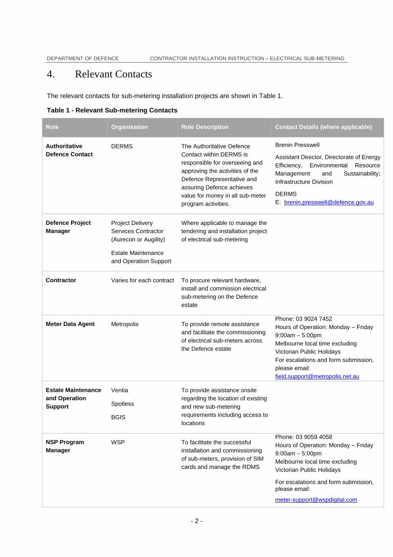
4. Relevant Contacts
The relevant contacts for sub-metering installation projects are shown in Table 1.
Table 1 - Relevant Sub-metering Contacts
Role Organisation Role Description Contact Details (where applicable)
Authoritative
Defence Contact
DERMS The Authoritative Defence
Contact within DERMS is
responsible for overseeing and
approving the activities of the
Defence Representative and
assuring Defence achieves
value for money in all sub-meter
program activities.
Brenin Presswell
Assistant Director, Directorate of Energy
Efficiency, Environmental Resource
Management and Sustainability;
Infrastructure Division
DERMS
Defence Project
Manager
Project Delivery
Services Contractor
(Aurecon or Augility)
Estate Maintenance
and Operation Support
Where applicable to manage the
tendering and installation project
of electrical sub-metering
Contractor Varies for each contract To procure relevant hardware,
install and commission electrical
sub-metering on the Defence
estate
Meter Data Agent Metropolis To provide remote assistance
and facilitate the commissioning
of electrical sub-meters across
the Defence estate
Phone: 03 9024 7452
Hours of Operation: Monday – Friday
9:00am – 5:00pm
Melbourne local time excluding
Victorian Public Holidays
For escalations and form submission,
please email:
Estate Maintenance
and Operation
Support
Ventia
Spotless
BGIS
To provide assistance onsite
regarding the location of existing
and new sub-metering
requirements including access to
locations
NSP Program
Manager
WSP To facilitate the successful
installation and commissioning
of sub-meters, provision of SIM
cards and manage the RDMS
Phone: 03 9059 4058
Hours of Operation: Monday – Friday
9:00am – 5:00pm
Melbourne local time excluding
Victorian Public Holidays
For escalations and form submission, please email:

DEPARTMENT OF DEFENCE CONTRACTOR INSTALLATION INSTRUCTION – ELECTRICAL SUB-METERING
- 3 -
Role Organisation Role Description Contact Details (where applicable)

DEPARTMENT OF DEFENCE CONTRACTOR INSTALLATION INSTRUCTION – ELECTRICAL SUB-METERING
- 4 -
SECTION 1 - PRE-SITE PLANNING AND
PROCUREMENT
OH&S and regulatory documents
The Contractor must submit OH&S and regulatory documents to relevant Defence Project Manager for
approval. No site work will be undertaken without the approval of the Defence Project Manager to do
so.
Appendix B lists all relevant legislation, standards and codes that shall be adhered to as part of the
procurement, installation and commissioning of the sub-meters.
Project Contact
The Contractor should confirm all relevant project contacts at project commencement (refer Table 1)
Notification of Non-Compliance
If the Contractor is aware of a non-compliances prior to attending site they must refer to the Defence
Project Manager if changes are required on approved design due to site constraints or other issues.
Resource Data Management System
The Contractor shall confirm with Defence Project Manager prior to installation that the sub-meter being
installed will be connected to Defence’s RDMS.
If the sub-meter is being installed into a different data management system (i.e. a Building Management
System (BMS) or a Power and Control Management System (PCMS)) then they should confirm the
commissioning requirements with the Defence Project Manager including whether the BMS or PCMS
shall be connected to the RDMS (see BMS-RDMS Connection Protocol).
Sub-metering Installation Schedule
The Contractor must submit a detailed installation schedule to the Defence Project Manager and provide
the schedule to the Meter Data Agent (MDA) for reference. This schedule will allow the MDA to prepare
for remote commissioning at the commissioning phase.
This information should be provided together with:
the number of meters being installed
the meter type and serial number for each meter
the modem type and serial number for each modem
DEPARTMENT OF DEFENCE CONTRACTOR INSTALLATION INSTRUCTION – ELECTRICAL SUB-METERING
- 5 -
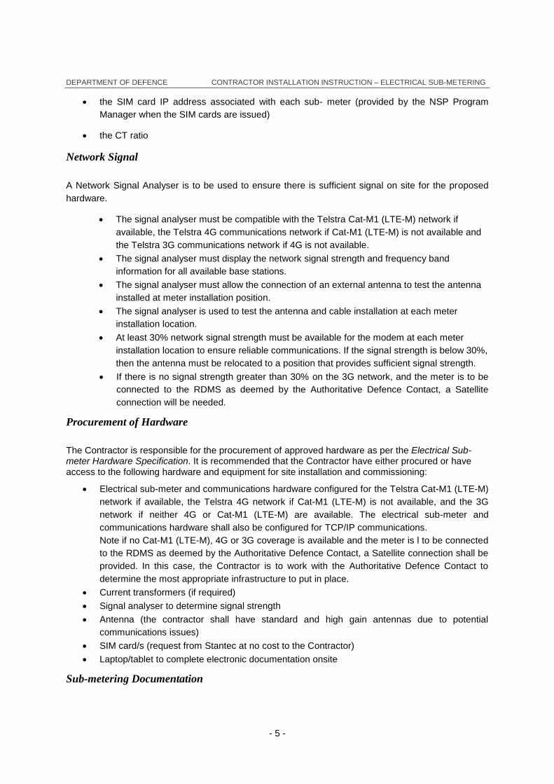
the SIM card IP address associated with each sub- meter (provided by the NSP Program
Manager when the SIM cards are issued)
the CT ratio
Network Signal
A Network Signal Analyser is to be used to ensure there is sufficient signal on site for the proposed
hardware.
The signal analyser must be compatible with the Telstra Cat-M1 (LTE-M) network if
available, the Telstra 4G communications network if Cat-M1 (LTE-M) is not available and
the Telstra 3G communications network if 4G is not available.
The signal analyser must display the network signal strength and frequency band
information for all available base stations.
The signal analyser must allow the connection of an external antenna to test the antenna
installed at meter installation position.
The signal analyser is used to test the antenna and cable installation at each meter
installation location.
At least 30% network signal strength must be available for the modem at each meter
installation location to ensure reliable communications. If the signal strength is below 30%,
then the antenna must be relocated to a position that provides sufficient signal strength.
If there is no signal strength greater than 30% on the 3G network, and the meter is to be
connected to the RDMS as deemed by the Authoritative Defence Contact, a Satellite
connection will be needed.
Procurement of Hardware
The Contractor is responsible for the procurement of approved hardware as per the Electrical Sub-meter Hardware Specification. It is recommended that the Contractor have either procured or have access to the following hardware and equipment for site installation and commissioning:
Electrical sub-meter and communications hardware configured for the Telstra Cat-M1 (LTE-M)
network if available, the Telstra 4G network if Cat-M1 (LTE-M) is not available, and the 3G
network if neither 4G or Cat-M1 (LTE-M) are available. The electrical sub-meter and
communications hardware shall also be configured for TCP/IP communications.
Note if no Cat-M1 (LTE-M), 4G or 3G coverage is available and the meter is l to be connected
to the RDMS as deemed by the Authoritative Defence Contact, a Satellite connection shall be
provided. In this case, the Contractor is to work with the Authoritative Defence Contact to
determine the most appropriate infrastructure to put in place.
Current transformers (if required)
Signal analyser to determine signal strength
Antenna (the contractor shall have standard and high gain antennas due to potential
communications issues)
SIM card/s (request from Stantec at no cost to the Contractor)
Laptop/tablet to complete electronic documentation onsite
Sub-metering Documentation

DEPARTMENT OF DEFENCE CONTRACTOR INSTALLATION INSTRUCTION – ELECTRICAL SUB-METERING
- 6 -
The Contractor must acquire the most up-to-date (on DEQMS) documents for the installation and
commissioning of electrical sub-meters. The following documents are to be pre-filled where possible
prior to site and then completed during meter installation.
Electricity New Meter Form
Meter Hierarchy Template
The Contractor must make contact with the Meter Data Agent at least two business days before the
scheduled installation to exchange the Electricity New Meter Form and provide other details as required
to prepare for meter provisioning. Refer to the Relevant Sub-metering Contacts section for contact
details.
Security Requirements and Site Notification
Prior to installation the contractor needs to confirm that the installation of the wireless meter/modem is
permitted at the design location, that all security requirements have been addressed, and that an
authorised building contact (e.g. Base Support Manager) has approved the installation and shut-down
process.
Site Access
To ensure that no delays occur due to site access issues the Contractor must confirm that:
All field technicians have appropriate site access and security credentials (access ID if required)
Contractor has obtained an authority/permit to work
Permission to bring laptop, electrical equipment and hardware onsite has been approved
through the Defence Project Manager
Permission to take photos has been approved through the Defence Project Manager
EMOS contractor is aware of works and can provide access (e.g. keys) to metering locations
If required the Electrical authority (Local) has been contacted
Defence Asset ID
The Contractor must ensure that a Defence asset registration number has been assigned and a sticker
obtained to be attached to the hardware installed onsite. This will be arranged through the Defence
Project Manager who may need to liaise with the EMOS for the site.
Shut Down
If required, the Contractor shall submit a site shutdown notification to the Defence Project Manager
prior to attending site. The Contractor will confirm with the Defence Project Manager the process
required for site shutdown.

DEPARTMENT OF DEFENCE CONTRACTOR INSTALLATION INSTRUCTION – ELECTRICAL SUB-METERING
- 7 -
SECTION 2 – SITE INSTALLATION
Notification of Non-Compliance
If the Contractor becomes aware of non-compliances while attending site and changes to
the approved design are required, the Contractor must refer to the Defence Project
Manager.
For retrofit projects, any alterations to existing infrastructure shall not compromise existing
protection measures (e.g. for switchboards fault withstands including arc fault current
protection, ingress protection or form of segregation. Refer to the requirements of AS/NZS
3000, AS/NZS 3439.1 and AS 4278).
Current Transformers (CTs) Installation
The following shall be considered by the Contractor if required to install new CTs or retrofitting sub-
meters to existing CTs:
Contractor shall ensure that new CTs meet the specification
Contractor shall install CTs of the correct physical size and with a CT ratio appropriate to the
application
Contractor shall confirm that any existing CTs are in good operating condition and appropriate
to the application. Where a CT is deemed to be not functioning, the Contractor must notify the
Defence Project Manager and replace with a new CT.
Any new CTs installed are not to compromise original switch design requirements
Contractor will ensure that CT wiring meets all relevant local and Australian Standards.
CT Ratio information must be correctly recorded and checked as part of the installation details.
Meter voltage connection
All active voltage conductors are to be coloured according to their phase (red, white or blue). The black meter neutral can be picked up from the neutral link. All wires are to be seven strands 2.5mm2 copper as per the Specification.
In general, smart meter and modem packages will be powered by a voltage connection and burden less than 10VA / 50mA per phase. Consult the hardware manufacturer’s data sheets for exact specifications.
If circuits are directly connected to the substation bus or main switchboard bus bars, HRC fuses are to be used because the fault currents in a bare-conductor short circuit can be extremely high.
Any voltage fuses installed beneath a fixed panel must be safely accessible without the need to disconnect power to the switchboard.

DEPARTMENT OF DEFENCE CONTRACTOR INSTALLATION INSTRUCTION – ELECTRICAL SUB-METERING
- 8 -
Meter Mounting Panel and Meter Test Blocks
The following shall be considered by the Contractor when installing the meter mounting panel and meter
test blocks:
AS3000 and Service Installation Rules (SIRs);
Sub-meters installed shall meet the Specification;
Contractor shall ensure that installations do not to intrude into passageways or present any
safety hazards;
Where Contractors are required to install meters in high security, prohibitive or sensitive areas
they must make note on the New Meter Form so future personnel wishing to access meters are
aware of potential impediment;
Meters shall remain accessible to be read, maintained or replaced without the need to
disconnect power from the switchboard;
Contractor shall ensure adequate shading and air circulation for any external installations;
Meter and modem are to remain clear of strong magnetic fields around heavy bus bars; and
Meter and modem shall be installed in a secure location to avoid the potential for vandalism
and/or theft of equipment.
Meter, modem and aerial
The installation steps to connect a standard electrical meter, modem and antenna package are:
1. Mounting of meter and modem (with installed SIM card) in the location designated by relevant
design documentation;
2. Connection of wiring between meter and meter test block (Note: wiring needs to ensure that
meter is reading usage or generation accurately and not reading generation when usage is
occurring or vice versa);
3. Connection of cabling between meter and modem;
o The radio modem is to be connected to the meter through the appropriate cable port,
noting that generally the meter supplies power and data to the modem through this
cable;
4. Mounting antenna at its nominated location;
o The antenna is to be placed in a location that produces signal strength of at least 30%,
but 60% signal strength or more is preferred
o Where the Contractor needs to undertake works for antenna installation (e.g. drilling for
wires) they must communicate with the Defence Project Manager and obtain the
required approvals.
5. Connection of antenna to modem; and
6. Removal of meter test block bridging links for CTs.
7. NOTE: Most radio modems have a maximum operating temperature around 55°C and will fail if
left exposed in full sun, similarly most meters have a maximum operating temperature around
70°C. Ensure adequate shading and air circulation for any external installations.

DEPARTMENT OF DEFENCE CONTRACTOR INSTALLATION INSTRUCTION – ELECTRICAL SUB-METERING
- 9 -
Antennas
Antennas are required at all sites to ensure adequate signal strength for reliable remote
communications.
The antenna must support the frequency bands used by the Telstra communication
network selected (preference is Cat-M1 (LTE-M) followed by 4G followed by 3G).
Low cost adhesive antennas must not be used unless there is no alternative due to
insufficient space to mount external omni-directional antennas with a gain of at least
2.0dBi.
Note that many high gain antennas only provide high gain in one frequency band that may
not be available at some installation locations. Please contact the Defence Representative
if unsure about a specific antenna type is suitable for the network and installation.
At least 30% network signal strength must be available for the modem at each meter
installation location to ensure reliable communications.
SIM Card
The SIM card is to be correctly inserted into the modem – consult the modem manual for additional
information and correct installation procedure.
Installation Documentation
The contractor shall ensure that the Electricity New Meter Form is completed at the end of each sub-
meter installation. This form is critical in the commissioning phase and ongoing maintenance of sub-
meters.
Where possible the Contractor shall take photos of the sub-meter, modem and current transformers for
reference and send to the Defence Project Manager with the Electricity New Meter Form as this provides
valuable information for meter rectification.

DEPARTMENT OF DEFENCE CONTRACTOR INSTALLATION INSTRUCTION – ELECTRICAL SUB-METERING
- 10 -
SECTION 3 - COMMISSIONING & SIGN OFF
Power up
The Contractor will perform a visual check of the installation to ensure all components have been
properly installed. This will be indicated by the LCD screen on the meter and correct sequence of status
indicators (such as LEDs) on the modem.
Network Signal Analyser
A Network Signal Analyser is to be used to ensure the modem and antenna installation are installed
correctly and allow for reliable remote meter reading operations.
The signal analyser must be compatible with the Telstra Cat-M1 (LTE-M) network if
available, the Telstra 4G network if Cat-M1 (LTE-M) is not available, and the 3G network if
neither 4G or Cat-M1 (LTE-M) are available..
The signal analyser must display the network signal strength and frequency band
information for all available base stations.
The signal analyser must allow the connection of an external antenna to test the antenna
installed at meter installation position.
The signal analyser is used to test the antenna and cable installation at each meter
installation location.
At least 30% network signal strength must be available for the modem at each meter
installation location to ensure reliable communications. If the signal strength is below 30%,
then the antenna must be relocated to a position that provides sufficient signal strength.
Verification of Installation
Verify that all elements of the installation are working correctly by viewing the following parameters on
the meter LCD display. If any of the following parameters are not available on the LCD display, the
Contractor will need to contact the MDA who will be able to perform a remote configuration, provided
wireless communications can be established.
Modem signal strength
o The modem signal strength is a sample taken at the moment when the modem starts
up. Minimum signal strength of at least 30% is required, but signal strength of 60% or
more is preferred.
Modem
o The modem status is normally shown by a sequence of LED indications. Contact the
MDA for assistance if required.
CT ratio
o In most cases, the CT ratio will not be set (basic CT ratio will be pre-programmed to
5/5) until the MDA configures the CT ratio remotely during the commissioning process.
GPS Location
o GPS location is required so that the physical location of the meter is known to parties
not involved in the physical installation of the meter. The Contractor should ensure that

DEPARTMENT OF DEFENCE CONTRACTOR INSTALLATION INSTRUCTION – ELECTRICAL SUB-METERING
- 11 -
the device used to obtain GPS co-ordinates is accurate within 10 meters of the actual
location.
Remote Commissioning and Verification
The Contractor shall contact and confirm the commissioning schedule with the MDA in advance so that
the final remote commissioning and verification can be performed efficiently. The Contractor shall remain
on site to make any required adjustments in real time.
The following information is required from the Contractor as a minimum to perform the remote
commissioning and verification (this information can be provided before the installations are complete if
known):
Meter model, type and serial number;
Modem model, type and serial number;
SIM serial number (ICCID), Phone Number (MSISDN) and IP address;
CT ratio for installed CTs;
Whether the meter is measuring usage, generation or both
Number of phases, voltage per phase, frequency; and
Photos for equipment installed.
The remote commissioning will be completed by the MDA which will include any additional meter configuration required. The remote commissioning will ensure the signal strength is satisfactory, end-to-end communications are working and that all components have been installed correctly. If any components are not working or have not been installed correctly, it is the responsibility of the Contractor to rectify the problem in consultation with the Defence Project Manager to perform the remote commissioning and verification.
Commissioning MDA: Metropolis Meter Transfers Team
03 9024 7453
Hours of Operation: Monday – Friday 8:00am – 4:00pm
Melbourne local time excluding Victorian Public Holidays
For escalations and form submission, please email:
The Contractor shall also advise the Defence Project Manager when commissioning will occur, and the
MDA shall advise the Defence Project Manager of commissioning outcomes.
Once satisfied, the Defence Project Manager, in consultation with the MDA and the NSP Program Manager, will acknowledge the installation as completed and ready for online data access.
Labelling
Permanent Traffolyte style labels shall be used, either screw fixed or glued. External labelling exposed
to the weather shall meet Defence Manual of Infrastructure Engineering – Electrical (MIEE)
requirements.
All new meters shall receive a Defence Asset identification number and associated sticker. This should
be co-ordinated through the Defence Project Manager.
Installation Documentation

DEPARTMENT OF DEFENCE CONTRACTOR INSTALLATION INSTRUCTION – ELECTRICAL SUB-METERING
- 12 -
The Contractor shall complete and submit Electricity New Meter Form, the Meter Hierarchy Form and
the Metering Strategy (part of the Smart Infrastructure Checklist) available on DEQMS to the Defence
Project Manager and the NSP Program Manager for each metering location. The project will not be
signed off until confirmation of completed project forms and fully commissioned sub-meters is received.

DEPARTMENT OF DEFENCE CONTRACTOR INSTALLATION INSTRUCTION – ELECTRICAL SUB-METERING
- 13 -
APPENDIX A – SUB-METERING CHECKLIST
Item Yes No Comments
PRE-SITE CHECKLIST
1. Have you provided the Defence Project Manager with
detailed metering installation schedule?
2. Have you provided the MDA with detailed metering
installation schedule (including meter numbers, SIM
numbers and IP addresses)?
3. Do you have an electronic new meter form and
electronic metering hierarchy form for each meter (from
DEQMS)?
4. Have you confirmed site access for technicians and
access to each metering location with EMOS
contractor?
5. Is the meter configured correctly for the modem being
installed and confirmed to be compatible with the MDA?
6. Has all equipment required been procured and is it
ready for installation (electricity meter, communications
hardware and cables, antenna and cables and SIM)?
SITE CHECKLIST
1. Has the new meter form and meter hierarchy form
been completed for each meter installed?
2. Has the MDA remotely commissioned each meter
and confirmed meter is reading?
3. Is the signal strength at the metering location greater
than 30%?
4. Have all meters been commissioned and
communications established and confirmed operational
prior to leaving site?

DEPARTMENT OF DEFENCE CONTRACTOR INSTALLATION INSTRUCTION – ELECTRICAL SUB-METERING
- 14 -
APPENDIX B – STANDARDS AND LEGISLATION
1. Standards and Codes
All local and National Electrical and Building Codes (Australian Standards) are applicable and must be
adhered to. Network standards are to be considered as a guide as the meters are to be installed on a
privately owned network.
Australian Standards, Legislation and Defence Guidelines:
Commonwealth Work Health and Safety Act, regulations and codes of practice;
Defence Manual of Infrastructure Engineering – Electrical (MIEE);
AS/NZS 3000 – ‘Electrical Installations’ (Wiring Rules);
AS/NZS 1939 – ‘Degrees of Protection Provided by Enclosures for Electrical Equipment’;
AS/NZS 3147 – Cable Manufacturing;
AS/NZS 61000 – ‘Electromagnetic Compatibility (EMC)’;
AS/NZS 60044.1-2003 – Current Transformers;
AS/NZS 60044.2-2003 – Voltage Transformers; and
All relevant State and Territory based legislation as governed by the agencies listed in Table
2.
2. Relevant state based agencies
Table 2: State and territory agencies governing electrical safety legislation
State Agency Contact
ACT ACT Planning and Land Authority, Worksafe ACT
www.actpla.act.gov.au www.worksafe.act.gov.au/health_safety
NSW NSW Fair Trading (Department of Finances and Services)
www.fairtrading.nsw.gov.auhttp://www.environmen
t.nsw.gov.au/
NT NT Worksafe www.worksafe.nt.gov.au
QLD Electrical Safety Office, Department of Justice
www.eso.qld.gov.au
SA
Office of the Technical Regulator, Office of Consumer and Business Affairs (licensing only)
www.technicalregulator.sa.gov.au www.ocba.sa.gov.au
Tas Workplace Standards Tasmania
www.wst.tas.gov.au/electricity
Vic Energy safe Victoria http://www.esv.vic.gov.au/
WA Department of Commerce www.energysafety.wa.gov.au

DEPARTMENT OF DEFENCE CONTRACTOR INSTALLATION INSTRUCTION – ELECTRICAL SUB-METERING
- 15 -
APPENDIX C – ELECTRONIC FORM EXAMPLES
1. New Meter Form

DEPARTMENT OF DEFENCE CONTRACTOR INSTALLATION INSTRUCTION – ELECTRICAL SUB-METERING
- 16 -
2. Meter Hierarchy Form
Meter Hierarchy TemplateThis template is used to describe the hierarchy of different meters to prevent double counting of usage data.
Site:
Project Name:
Project Stage:
Date:
Defence site name
E.g. For Tender, As-Constructed
Met
er ID
Ref
erence
HV c
onnec
tion
Sub-S
tatio
n
LV D
istrib
ution P
illar
Sub-L
V D
istrib
ution
Pill
ar
Build
ing M
SB
Dis
trib
ution B
oard
Dis
trib
ution
Ref
erence
Com
men
t
211111111 X Site HV Connection (existing)
211111112 X Sub-Station 5 (existing)
211111113 X Pillar 5A
211111114 X Pillar 5B
211111111 X Site HV Connection (existing)
211111115 X Sub-Station 6
211111116 X 0121/A104 - Base Offices
211111117 X 0121/A105 - Base Offices
211111111 X Site HV Connection (existing)
211111118 X Sub-Station 7
- X Pillar 7A
211111119 X 0121/D101 - Accommodation
211111120 X Floor 1
211111121 X Floor 2
211111122 X 0121/D102 - Accommodation
211111123 X Floor 1
211111124 X Floor 2
211111125 X 0121/D103 - Accommodation
211111126 X Floor 1
211111127 X Floor 2
Insert a break between different meter hierarchy groups.
Provide clarity on system hierarchy
Tie the hierarchy back to an existing connection point if possible (i.e. Site HV or existing sub-
station and note as such in comments).
Provide additional detail or note changes in hierarchy between
submissions, as required.