Embed Size (px)
Citation preview
1
International Conference on Ships and Offshore Structures
ICSOS 2017
11 – 13 September 2017, Shenzhen, China
Contribution of a deformable striking-ship structure to the
structural crashworthiness of ship-ship collisions
Yeong Gook Koa, Sang Jin Kim
b, Jeom Kee Paik
a,b,c,*1
a Department of Naval Architecture and Ocean Engineering, Pusan National University, Busan 46241, Republic of Korea
b The Korea Ship and Offshore Research Institute (The Lloyd’s Register Foundation Research Centre of Excellence), Pusan
National University, Busan 46241, Republic of Korea c Department of Mechanical Engineering, University College London, London, WC1E 7JE, UK
Abstract
Ship-ship collision is one of the most frequent types of accidents in shipping industry. The risks of massive
financial losses and marine pollution have been increasing due to ship-ship collisions where large oil tankers or
liquefied natural gas (LNG)-fueled ships can be involved in the accidents. Various types of methods are available
for the purpose of safety studies in association with structural crashworthiness involving crushing and fracture in
ship-ship collisions. In the perspectives of multi-physics and multi-criteria involved, however, the nonlinear finite
element method is certainly one of the most powerful techniques to model the problems. In a ship-ship collision
accident where the bow of a striking ship is collided with the side of struck ship, the kinetic energy must be
absorbed by both striking and struck ship structures in terms of collision damages and corresponding strain
energies. As the bow structure of the striking ship is usually much stiffer than the side structure of the struck ship,
the former has been modelled as a rigid body in the industry practice that does not allow deformation or damage so
that no contribution to the energy absorption is made by the striking body. As the energy absorption characteristics
of the striking ship depends on the structural arrangement of bulbous bow and flare, however, the contribution of
striking ship cannot be entirely neglected. The aims of the present study are to examine the effects of a deformable
striking ship structure on the structural crashworthiness of ship-ship collisions using LS-DYNA nonlinear finite
element method computations. As an illustrative example in the paper, the struck ship is a VLCC class double hull
oil tanker, while the struck ships are two types: a VLCC class tanker and a SUEZMAX class tanker. The
relationships between collision forces versus penetration together with their energy absorption capabilities are
characterized in association with the contributions of the striking ship bow where the deformable striking ship
structures are compared with the rigid striking ship structures. Findings and insights developed from the present
study are summarized. Details of the computations are documented.
Keywords: Ship-ship collision; deformable striking bow; oil tanker; structural crashworthiness; nonlinear finite element analysis.
1. Introduction
Accidental limit states (ALS) potentially brings about a catastrophe of serious injury or loss of life,
environmental damage and loss of property or considerable expenditure of finance. The aim of ALS
design is to ensure that the structure is able to bear up under specified accidental events such collision,
grounding, fire and explosion and to enable evacuation of personnel from the structure for a sufficient
period under specific environmental conditions after accidents occur (Paik and Thayamballi 2003,
2007).
Limit state design and safety assessment relevant to collisions and grounding are generally based on
the energy absorption capability of the structure until accidental limit state is reached. As the energy
absorption capability can be calculated by integration of the area below the reaction force versus
* Corresponding author. Tel.: +82-051-510-2429; fax: +82-051-518-7687.
E-mail address: [email protected]
2
penetration curve of the structure, the improving structural crashworthiness of the ships must be
fulfilled to obtain the resultant force versus penetration relation of the structure in the accidental event.
As the amount of energy dissipation at the fore part of the striking ship is low comparatively than at
the side part of the struck ship and conservative evaluations are relevant especially for safety designs in
general, most ship collision simulations have been undertaken in the past where striking ships were
modelled as a rigid body (Ammerman and Daidola 1996, Wisniewski and Kolakowski 2002, Haris and
Amdahl 2011, Montewka et al. 2012, Sun et al. 2015, Zhang et al. 2016). On the other hand, some other
studies have of course been conducted with striking ships that were modelled as a deformable body
(Hogström and Ringsberg 2012, Haris and Amdahl 2013, Storheim and Amdahl 2015), but it is obvious
that more efforts are recommended to examine the contribution of realistic striking ships to the
structural crashworthiness of ship-ship collisions.
The aim of this study is to investigate the effects of a deformable striking-ship structure on the
structural crashworthiness in ship-ship collisions. The characteristics of the energy absorption
capabilities of ship structures in collision or grounding were studied in the literature by many
investigators using the non-linear finite element method (Amdahl 1983, Simonsen 1997, Zhang 1999,
Tornqvist 2003, Urban 2003, Alsos 2008, Hong 2009, Ehlers et al. 2010, 2016, Storheim and Amdahl
2015). This study also uses the non-linear finite element method with the LS-DYNA code (Hallquist
2010).
2. Collision Scenarios
Among various type of ships, oil tanker which can bring about a significant amount of pollution has
been utilized as a target structure in the simulations and a host of researchers have fulfilled studies with
oil tankers to reduce loss of financial properties and to prevent loss of lives and environmental damages
in the literature (Zheng et al. 2007, Tavakoli et al. 2010, Kim et al. 2015, Faisal et al. 2016, Parunov et
al. 2016, Youssef et al. 2014, 2017).
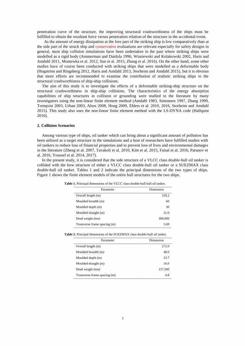
In the present study, it is considered that the side structure of a VLCC class double-hull oil tanker is
collided with the bow structure of either a VLCC class double-hull oil tanker or a SUEZMAX class
double-hull oil tanker. Tables 1 and 2 indicate the principal dimensions of the two types of ships.
Figure 1 shows the finite element models of the entire hull structures for the two ships.
Table 1. Principal dimensions of the VLCC class double-hull hull oil tanker.
Parameter Dimension
Overall length (m) 318.2
Moulded breadth (m) 60
Moulded depth (m) 30
Moulded draught (m) 21.6
Dead weight (ton) 300,000
Transverse frame spacing (m) 5.69
Table 2. Principal dimensions of the SUEZMAX class double-hull oil tanker.
Parameter Dimension
Overall length (m) 272.0
Moulded breadth (m) 48.0
Moulded depth (m) 23.7
Moulded draught (m) 16.0
Dead weight (ton) 157,500
Transverse frame spacing (m) 4.8
3
Figure 1. The VLCC class (left) and SUEZMAX class (right) double-hull oil tankers.
Collision scenarios considered in the present study are as follows:
Case A: The side structure of the VLCC class double-hull oil tanker is struck by the bow structure of
the VLCC class double-hull oil tanker
Case B: The side structure of the VLCC class double-hull oil tanker is struck by the bow structure of
the SUEZMAX class double-hull oil tanker
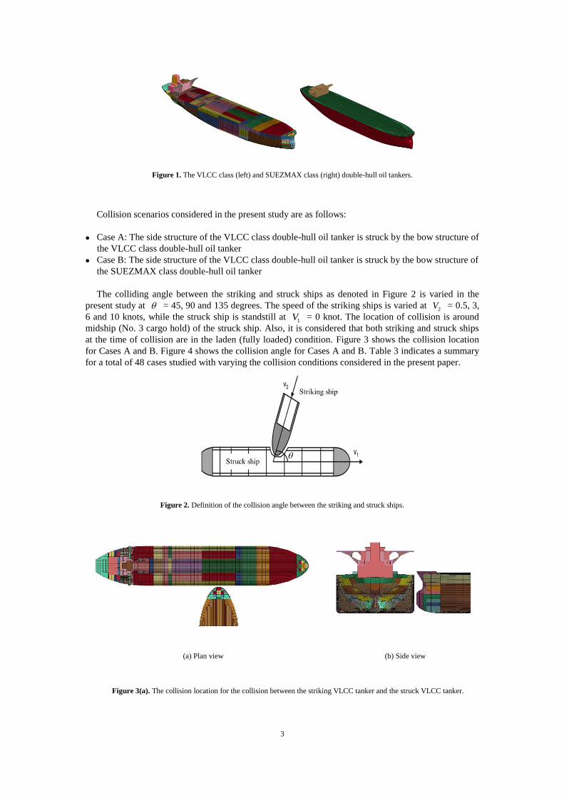
The colliding angle between the striking and struck ships as denoted in Figure 2 is varied in the
present study at = 45, 90 and 135 degrees. The speed of the striking ships is varied at 2V = 0.5, 3,
6 and 10 knots, while the struck ship is standstill at 1V = 0 knot. The location of collision is around
midship (No. 3 cargo hold) of the struck ship. Also, it is considered that both striking and struck ships
at the time of collision are in the laden (fully loaded) condition. Figure 3 shows the collision location
for Cases A and B. Figure 4 shows the collision angle for Cases A and B. Table 3 indicates a summary
for a total of 48 cases studied with varying the collision conditions considered in the present paper.
Figure 2. Definition of the collision angle between the striking and struck ships.
(a) Plan view (b) Side view
Figure 3(a). The collision location for the collision between the striking VLCC tanker and the struck VLCC tanker.
4
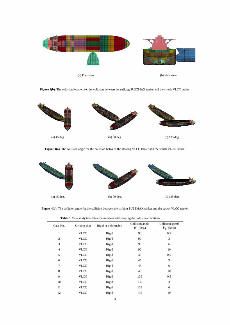
(a) Plan view (b) Side view
Figure 3(b). The collision location for the collision between the striking SUEZMAX tanker and the struck VLCC tanker.
(a) 45 deg. (b) 90 deg. (c) 135 deg.
Figure 4(a). The collision angle for the collision between the striking VLCC tanker and the struck VLCC tanker.
(a) 45 deg. (b) 90 deg. (c) 135 deg.
Figure 4(b). The collision angle for the collision between the striking SUEZMAX tanker and the struck VLCC tanker.
Table 3. Case study identification numbers with varying the collision conditions.
Case No. Striking ship Rigid or deformable Collision angle
(deg.)
Collision speed
2V (knot)
1 VLCC Rigid 90 0.5
2 VLCC Rigid 90 3
3 VLCC Rigid 90 6
4 VLCC Rigid 90 10
5 VLCC Rigid 45 0.5
6 VLCC Rigid 45 3
7 VLCC Rigid 45 6
8 VLCC Rigid 45 10
9 VLCC Rigid 135 0.5
10 VLCC Rigid 135 3
11 VLCC Rigid 135 6
12 VLCC Rigid 135 10
5
13 VLCC Deformable 90 0.5
14 VLCC Deformable 90 3
15 VLCC Deformable 90 6
16 VLCC Deformable 90 10
17 VLCC Deformable 45 0.5
18 VLCC Deformable 45 3
19 VLCC Deformable 45 6
20 VLCC Deformable 45 10
21 VLCC Deformable 135 0.5
22 VLCC Deformable 135 3
23 VLCC Deformable 135 6
24 VLCC Deformable 135 10
25 SUEZMAX Rigid 90 0.5
26 SUEZMAX Rigid 90 3
27 SUEZMAX Rigid 90 6
28 SUEZMAX Rigid 90 10
29 SUEZMAX Rigid 45 0.5
30 SUEZMAX Rigid 45 3
31 SUEZMAX Rigid 45 6
32 SUEZMAX Rigid 45 10
33 SUEZMAX Rigid 135 0.5
34 SUEZMAX Rigid 135 3
35 SUEZMAX Rigid 135 6
36 SUEZMAX Rigid 135 10
37 SUEZMAX Deformable 90 0.5
38 SUEZMAX Deformable 90 3
39 SUEZMAX Deformable 90 6
40 SUEZMAX Deformable 90 10
41 SUEZMAX Deformable 45 0.5
42 SUEZMAX Deformable 45 3
43 SUEZMAX Deformable 45 6
44 SUEZMAX Deformable 45 10
45 SUEZMAX Deformable 135 0.5
46 SUEZMAX Deformable 135 3
47 SUEZMAX Deformable 135 6
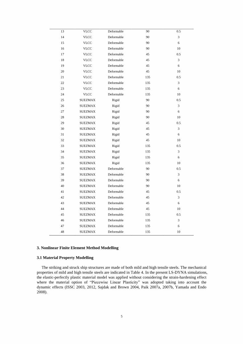
48 SUEZMAX Deformable 135 10
3. Nonlinear Finite Element Method Modelling
3.1 Material Property Modelling
The striking and struck ship structures are made of both mild and high tensile steels. The mechanical
properties of mild and high tensile steels are indicated in Table 4. In the present LS-DYNA simulations,
the elastic-perfectly plastic material model was applied without considering the strain-hardening effect
where the material option of “Piecewise Linear Plasticity” was adopted taking into account the
dynamic effects (ISSC 2003, 2012, Sajdak and Brown 2004, Paik 2007a, 2007b, Yamada and Endo
2008).
6
Table 4. Material properties of the striking and struck ship structures.
Material property Mild steel High-tensile steel
AH32 AH36
Density, ρ (ton/m3) 7.85 7.85 7.85
Young’s modulus, E (MPa) 205,800 205,800 205,800
Poisson’s ratio 0.3 0.3 0.3
Yield stress, σY (MPa) 235 315 355
Cowper-Symonds
coefficient
C 40.4 3200 3200
q 5 5 5
3.2 Finite Element Size
As the structural crashworthiness in ship-ship collisions involves crushing and fracture, it is
important to assign relevant mesh sizes in the finite element method modelling. In the present study,
only plate-shell elements with an aspect ratio of almost unity were used but without beam elements.
For the structural areas that are less affected by the collision, i.e., except for the cargo hold number 3 of
the struck ship as well as the striking ship bow, coarse meshes were used in that plating was modelled
by elements with about 1,000 mm in size and stiffener webs were modelled by one element while
stiffener flanges were modelled by one element for an angle type or two elements for a T-type.
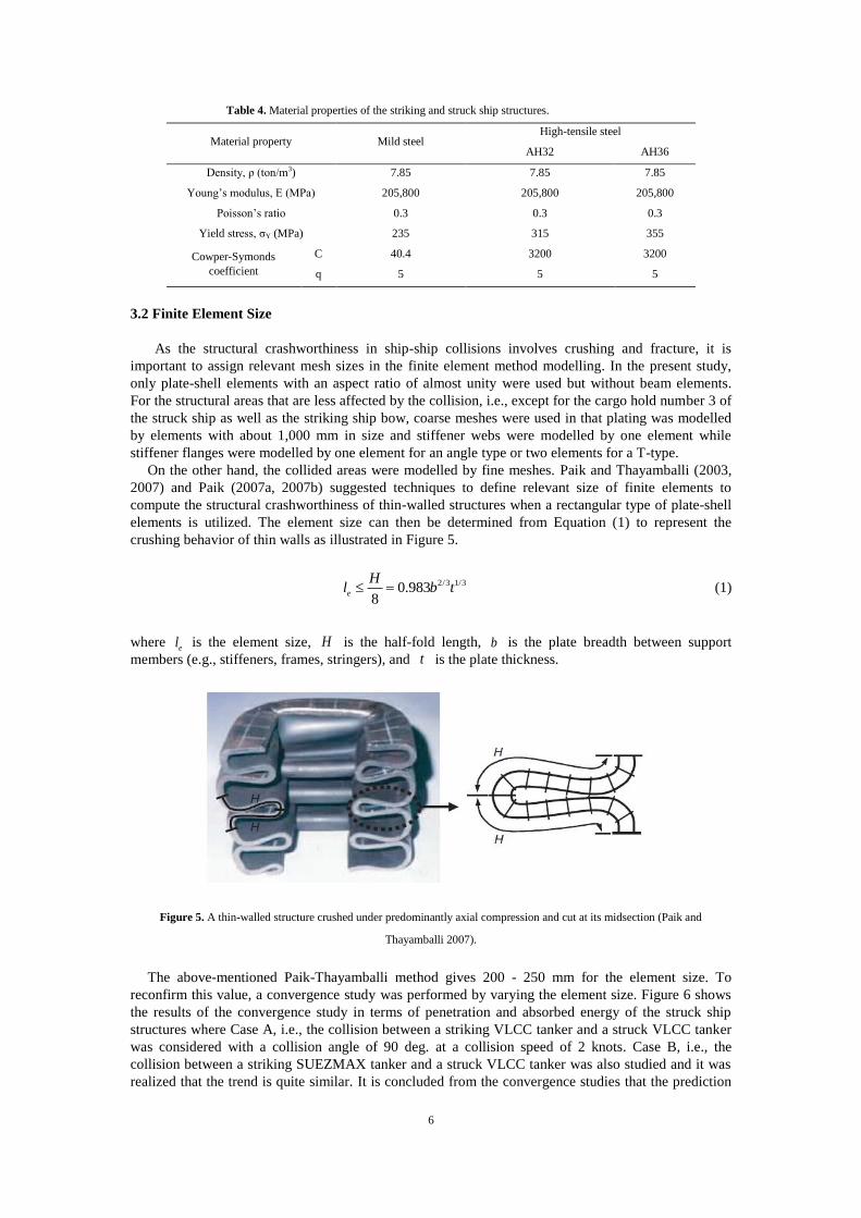
On the other hand, the collided areas were modelled by fine meshes. Paik and Thayamballi (2003,
2007) and Paik (2007a, 2007b) suggested techniques to define relevant size of finite elements to
compute the structural crashworthiness of thin-walled structures when a rectangular type of plate-shell
elements is utilized. The element size can then be determined from Equation (1) to represent the
crushing behavior of thin walls as illustrated in Figure 5.
2/3 1/30.9838
e
Hl b t (1)
where el is the element size, H is the half-fold length, b is the plate breadth between support
members (e.g., stiffeners, frames, stringers), and t is the plate thickness.
Figure 5. A thin-walled structure crushed under predominantly axial compression and cut at its midsection (Paik and
Thayamballi 2007).
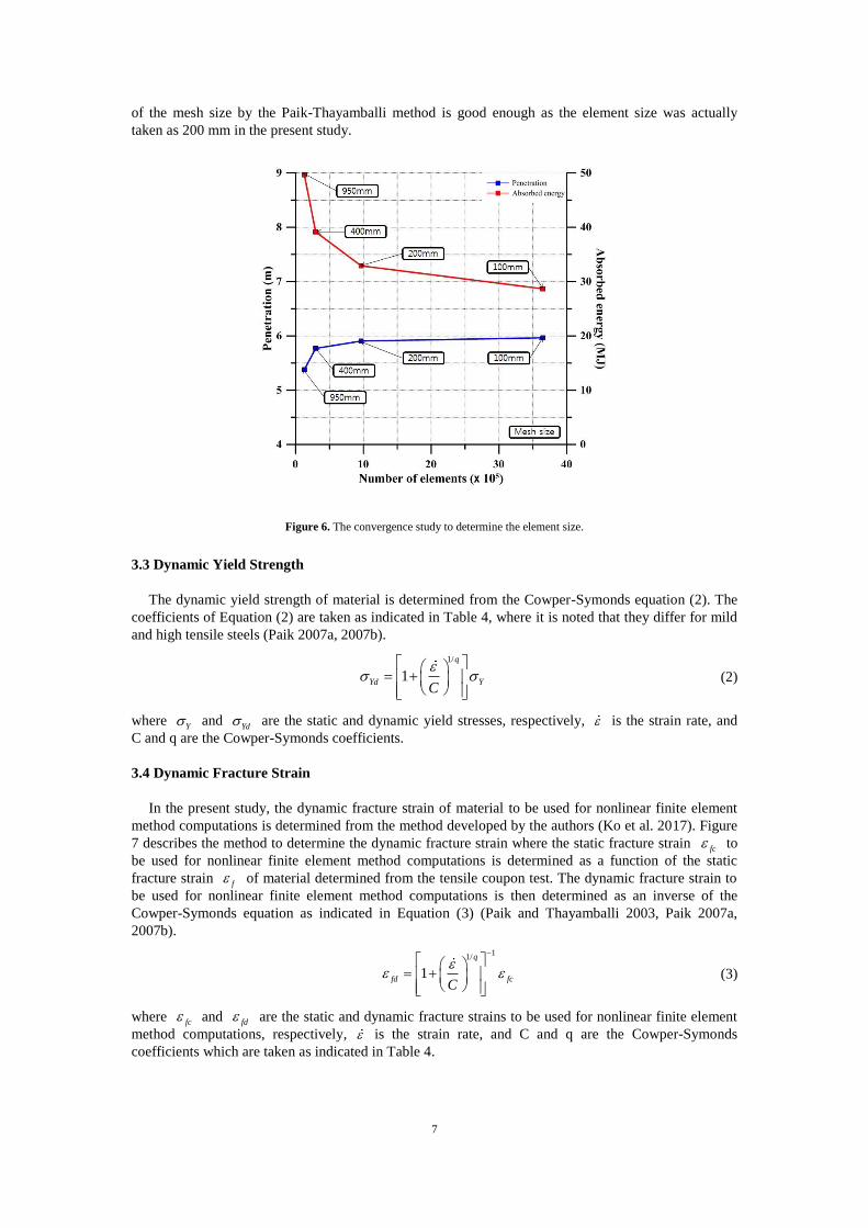
The above-mentioned Paik-Thayamballi method gives 200 - 250 mm for the element size. To
reconfirm this value, a convergence study was performed by varying the element size. Figure 6 shows
the results of the convergence study in terms of penetration and absorbed energy of the struck ship
structures where Case A, i.e., the collision between a striking VLCC tanker and a struck VLCC tanker
was considered with a collision angle of 90 deg. at a collision speed of 2 knots. Case B, i.e., the
collision between a striking SUEZMAX tanker and a struck VLCC tanker was also studied and it was
realized that the trend is quite similar. It is concluded from the convergence studies that the prediction
7
of the mesh size by the Paik-Thayamballi method is good enough as the element size was actually
taken as 200 mm in the present study.
Figure 6. The convergence study to determine the element size.
3.3 Dynamic Yield Strength
The dynamic yield strength of material is determined from the Cowper-Symonds equation (2). The
coefficients of Equation (2) are taken as indicated in Table 4, where it is noted that they differ for mild
and high tensile steels (Paik 2007a, 2007b).
1/
1
q
Yd YC
(2)
where Y and
Yd are the static and dynamic yield stresses, respectively, is the strain rate, and
C and q are the Cowper-Symonds coefficients.
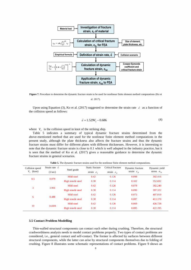
3.4 Dynamic Fracture Strain
In the present study, the dynamic fracture strain of material to be used for nonlinear finite element
method computations is determined from the method developed by the authors (Ko et al. 2017). Figure
7 describes the method to determine the dynamic fracture strain where the static fracture strain fc to
be used for nonlinear finite element method computations is determined as a function of the static
fracture strain f of material determined from the tensile coupon test. The dynamic fracture strain to
be used for nonlinear finite element method computations is then determined as an inverse of the
Cowper-Symonds equation as indicated in Equation (3) (Paik and Thayamballi 2003, Paik 2007a,
2007b).
11/
1
q
fd fcC
(3)
where fc
and fd
are the static and dynamic fracture strains to be used for nonlinear finite element
method computations, respectively, is the strain rate, and C and q are the Cowper-Symonds
coefficients which are taken as indicated in Table 4.
8
Figure 7. Procedure to determine the dynamic fracture strain to be used for nonlinear finite element method computations (Ko et
al. 2017).
Upon using Equation (3), Ko et al. (2017) suggested to determine the strain rate as a function of
the collision speed as follows:
21.529 0.686V
(4)
where 2V is the collision speed in knot of the striking ship.
Table 5 indicates a summary of typical dynamic fracture strains determined from the
above-mentioned method that are used for the nonlinear finite element method computations in the
present study, although the plate thickness also affects the fracture strains and thus the dynamic
fracture strains must differ for different plates with different thicknesses. However, it is interesting to
note that the dynamic fracture strain is close to 0.1 which is well adopted in the industry practice, but it
is seen that the method of Ko et al. (2017) gives a reasonable guidance to determine the dynamic
fracture strains in general scenarios.
Table 5. The dynamic fracture strains used for the nonlinear finite element method computations.
Collision speed
2V (knot)
Strain rate
(1/sec) Steel grade
Static fracture
strain f
Critical fracture
strain fc
Dynamic fracture
strain fd
Dynamic yield
stress Yd
0.5 0.079 Mild steel 0.42 0.126 0.098 302.416
High tensile steel 0.38 0.114 0.102 352.692
3 3.901 Mild steel 0.42 0.126 0.078 382.240
High tensile steel 0.38 0.114 0.090 397.322
6 8.488 Mild steel 0.42 0.126 0.073 407.010
High tensile steel 0.38 0.114 0.087 411.170
10 14.604 Mild steel 0.42 0.126 0.069 426.728
High tensile steel 0.38 0.114 0.085 422.195
3.5 Contact Problem Modelling
Thin-walled structural components can contact each other during crushing. Therefore, the structural
crashworthiness analysis needs to model contact problems properly. Two types of contact problems are
considered, i.e., general contact and self-contact. The former is affected by surfaces between different
structural components, while the latter can arise by structural components themselves due to folding of
crushing. Figure 8 illustrates some schematic representations of contact problems. Figure 9 shows an
Investigation of fracture
strain, εf of material
Definition of strain rate, ε·
Calculation of critical fracture
strain, εfc for FEA
Calculation of dynamic
fracture strain, εfd
Application of dynamic
fracture strain, εfd to FEA
Material test
Collision scenarioEmpirical formula
Cowper-Symonds
coefficient and
critical fracture strain
Size of element,
plate thickness, etc.
9
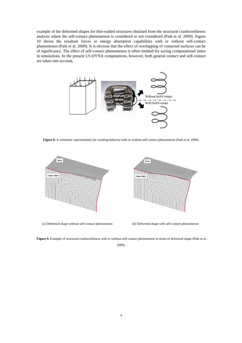
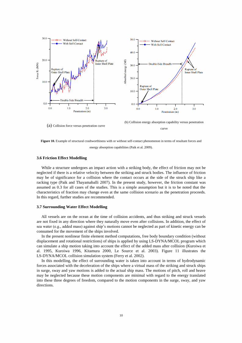
example of the deformed shapes for thin-walled structures obtained from the structural crashworthiness
analysis where the self-contact phenomenon is considered or not considered (Paik et al. 2009). Figure
10 shows the resultant forces or energy absorption capabilities with or without self-contact
phenomenon (Paik et al. 2009). It is obvious that the effect of overlapping of contacted surfaces can be
of significance. The effect of self-contact phenomenon is often omitted for saving computational times
in simulations. In the present LS-DYNA computations, however, both general contact and self-contact
are taken into account.
Figure 8. A schematic representation for crushing behavior with or without self-contact phenomenon (Paik et al. 2009).
(a) Deformed shape without self-contact phenomenon (b) Deformed shape with self-contact phenomenon
Figure 9. Example of structural crashworthiness with or without self-contact phenomenon in terms of deformed shape (Paik et al.
2009).
10
(a) Collision force versus penetration curve (b) Collision energy absorption capability versus penetration
curve
Figure 10. Example of structural crashworthiness with or without self-contact phenomenon in terms of resultant forces and
energy absorption capabilities (Paik et al. 2009).
3.6 Friction Effect Modelling
While a structure undergoes an impact action with a striking body, the effect of friction may not be
neglected if there is a relative velocity between the striking and struck bodies. The influence of friction
may be of significance for a collision where the contact occurs at the side of the struck ship like a
racking type (Paik and Thayamaballi 2007). In the present study, however, the friction constant was
assumed as 0.3 for all cases of the studies. This is a simple assumption but it is to be noted that the
characteristics of fraction may change even at the same collision scenario as the penetration proceeds.
In this regard, further studies are recommended.
3.7 Surrounding Water Effect Modelling
All vessels are on the ocean at the time of collision accidents, and thus striking and struck vessels
are not fixed in any direction where they naturally move even after collisions. In addition, the effect of
sea water (e.g., added mass) against ship’s motions cannot be neglected as part of kinetic energy can be
consumed for the movement of the ships involved.
In the present nonlinear finite element method computations, free body boundary condition (without
displacement and rotational restrictions) of ships is applied by using LS-DYNA/MCOL program which
can simulate a ship motion taking into account the effect of the added mass after collision (Kuroiwa et
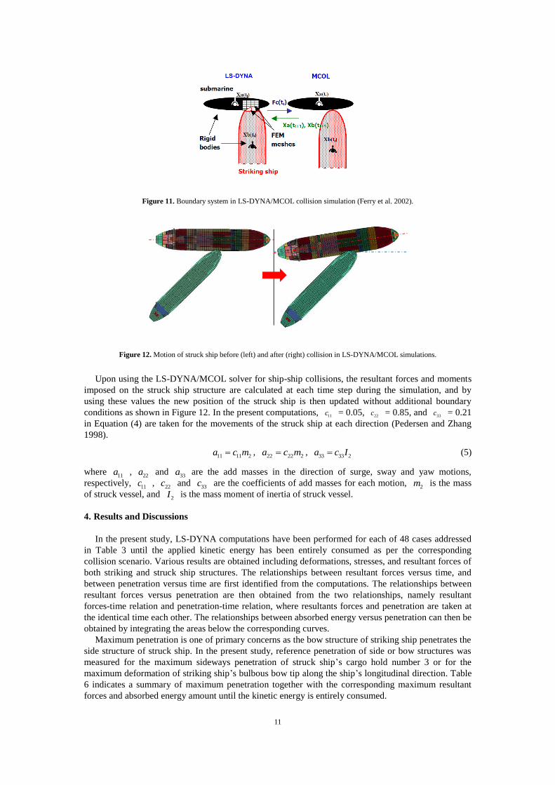
al. 1995, Kuroiwa 1996, Kitamura 2000, Le Source et al. 2003). Figure 11 illustrates the
LS-DYNA/MCOL collision simulation system (Ferry et al. 2002).
In this modelling, the effect of surrounding water is taken into account in terms of hydrodynamic
forces associated with the deceleration of the ships where a virtual mass of the striking and struck ships
in surge, sway and yaw motions is added to the actual ship mass. The motions of pitch, roll and heave
may be neglected because these motion components are minimal with regard to the energy translated
into these three degrees of freedom, compared to the motion components in the surge, sway, and yaw
directions.
11
Figure 11. Boundary system in LS-DYNA/MCOL collision simulation (Ferry et al. 2002).
Figure 12. Motion of struck ship before (left) and after (right) collision in LS-DYNA/MCOL simulations.
Upon using the LS-DYNA/MCOL solver for ship-ship collisions, the resultant forces and moments
imposed on the struck ship structure are calculated at each time step during the simulation, and by
using these values the new position of the struck ship is then updated without additional boundary
conditions as shown in Figure 12. In the present computations, 11c = 0.05, 22c = 0.85, and 33c = 0.21
in Equation (4) are taken for the movements of the struck ship at each direction (Pedersen and Zhang
1998).
11 11 2a c m , 22 22 2a c m ,
33 33 2a c I (5)
where 11a ,
22a and 33a are the add masses in the direction of surge, sway and yaw motions,
respectively, 11c ,
22c and 33c are the coefficients of add masses for each motion,
2m is the mass
of struck vessel, and 2I is the mass moment of inertia of struck vessel.
4. Results and Discussions
In the present study, LS-DYNA computations have been performed for each of 48 cases addressed
in Table 3 until the applied kinetic energy has been entirely consumed as per the corresponding
collision scenario. Various results are obtained including deformations, stresses, and resultant forces of
both striking and struck ship structures. The relationships between resultant forces versus time, and
between penetration versus time are first identified from the computations. The relationships between
resultant forces versus penetration are then obtained from the two relationships, namely resultant
forces-time relation and penetration-time relation, where resultants forces and penetration are taken at
the identical time each other. The relationships between absorbed energy versus penetration can then be
obtained by integrating the areas below the corresponding curves.
Maximum penetration is one of primary concerns as the bow structure of striking ship penetrates the
side structure of struck ship. In the present study, reference penetration of side or bow structures was
measured for the maximum sideways penetration of struck ship’s cargo hold number 3 or for the
maximum deformation of striking ship’s bulbous bow tip along the ship’s longitudinal direction. Table
6 indicates a summary of maximum penetration together with the corresponding maximum resultant
forces and absorbed energy amount until the kinetic energy is entirely consumed.
12
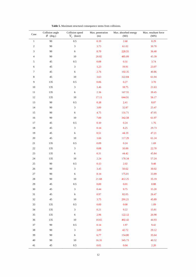
Table 5. Maximum structural consequence stems from collisions.
Case Collision angle
(deg.)
Collision speed
2V (knot)
Max. penetration
(m)
Max. absorbed energy
(MJ)
Max. resultant force
(MN)
1 90 0.5 0.19 2.60 8.29
2 90 3 3.73 61.02 30.70
3 90 6 8.70 220.55 36.40
4 90 10 20.82 485.09 45.39
5 45 0.5 0.08 0.31 3.74
6 45 3 1.23 19.91 23.07
7 45 6 2.76 102.35 40.86
8 45 10 3.63 322.84 61.04
9 135 0.5 0.06 0.27 3.70
10 135 3 1.46 18.75 21.63
11 135 6 2.36 167.55 39.45
12 135 10 17.11 644.91 56.17
13 90 0.5 0.18 2.41 8.07
14 90 3 3.00 32.87 25.47
15 90 6 4.75 131.71 47.05
16 90 10 7.00 342.58 61.97
17 45 0.5 0.10 0.24 1.76
18 45 3 0.14 8.25 29.73
19 45 6 0.51 44.19 47.21
20 45 10 1.66 117.29 61.24
21 135 0.5 0.09 0.24 1.69
22 135 3 0.08 10.00 22.70
23 135 6 0.31 44.42 45.84
24 135 10 2.24 170.34 57.24
25 90 0.5 0.13 2.02 9.48
26 90 3 3.45 50.62 30.02
27 90 6 8.14 175.01 33.89
28 90 10 21.68 412.25 35.19
29 45 0.5 0.00 0.01 0.88
30 45 3 0.44 9.75 15.20
31 45 6 0.97 82.05 26.47
32 45 10 3.75 291.21 45.89
33 135 0.5 0.00 0.00 1.09
34 135 3 0.21 9.22 15.81
35 135 6 2.96 122.12 26.98
36 135 10 10.65 402.42 44.93
37 90 0.5 0.14 1.97 9.42
38 90 3 3.09 42.72 29.12
39 90 6 6.77 154.80 35.64
40 90 10 16.31 345.73 40.52
41 45 0.5 0.01 0.04 2.20
13
42 45 3 1.01 12.26 24.68
43 45 6 1.94 84.70 38.39
44 45 10 3.27 313.53 55.03
45 135 0.5 0.01 0.02 2.16
46 135 3 1.25 10.00 22.70
47 135 6 2.22 87.45 39.32
48 135 10 5.33 303.58 50.82
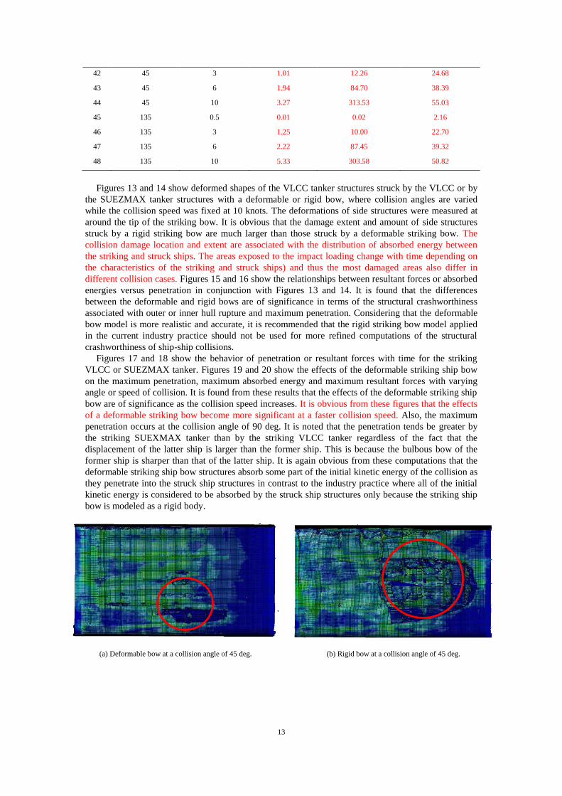
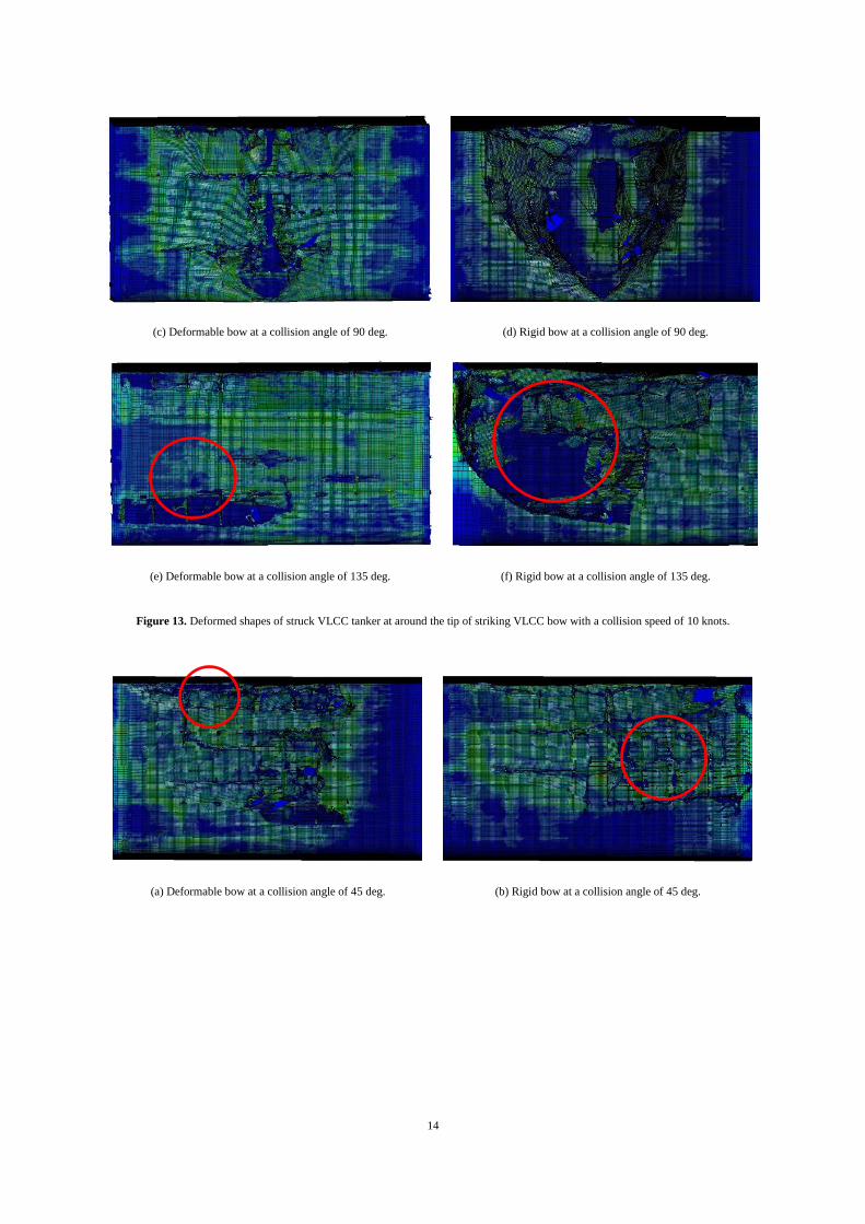
Figures 13 and 14 show deformed shapes of the VLCC tanker structures struck by the VLCC or by
the SUEZMAX tanker structures with a deformable or rigid bow, where collision angles are varied
while the collision speed was fixed at 10 knots. The deformations of side structures were measured at
around the tip of the striking bow. It is obvious that the damage extent and amount of side structures
struck by a rigid striking bow are much larger than those struck by a deformable striking bow. The
collision damage location and extent are associated with the distribution of absorbed energy between
the striking and struck ships. The areas exposed to the impact loading change with time depending on
the characteristics of the striking and struck ships) and thus the most damaged areas also differ in
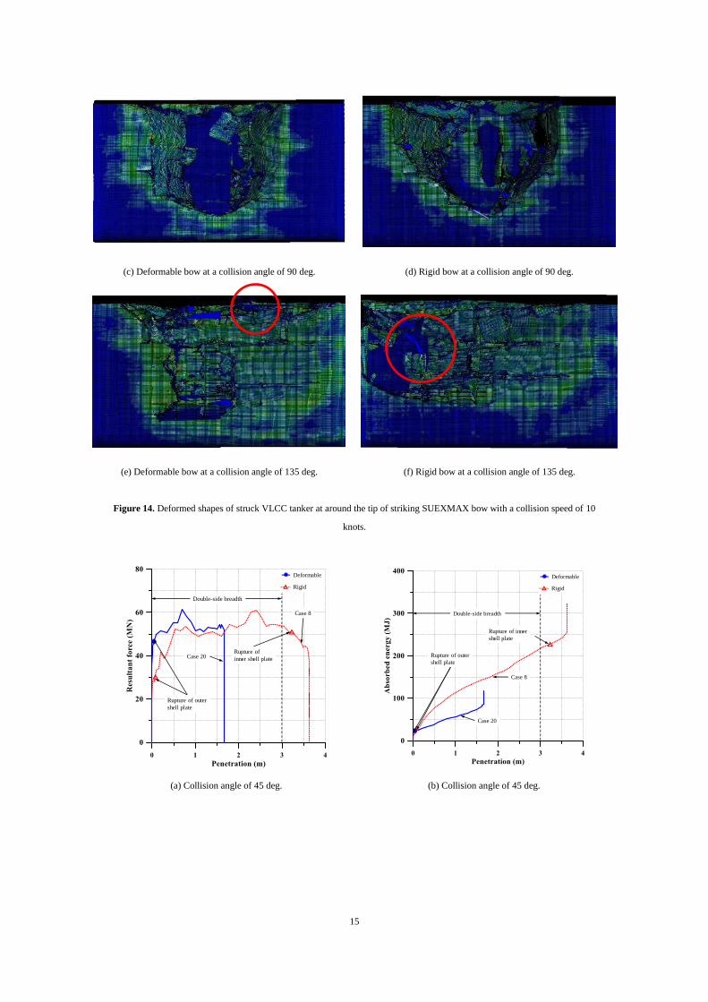
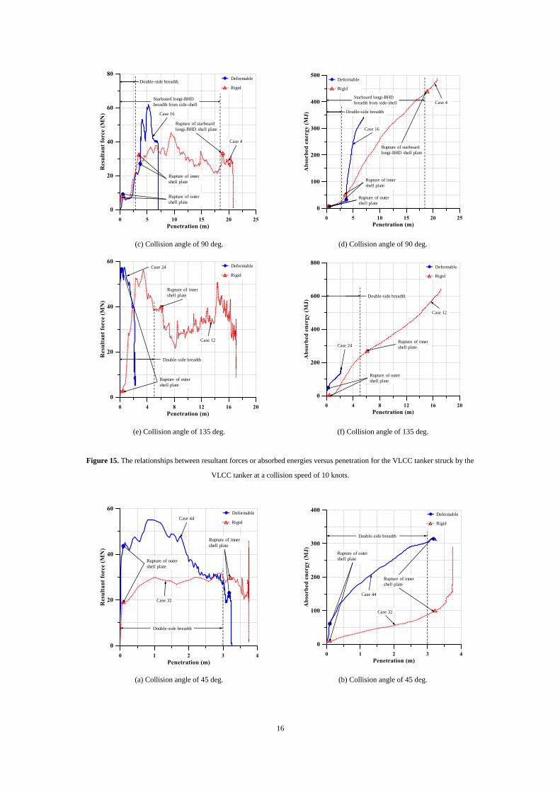
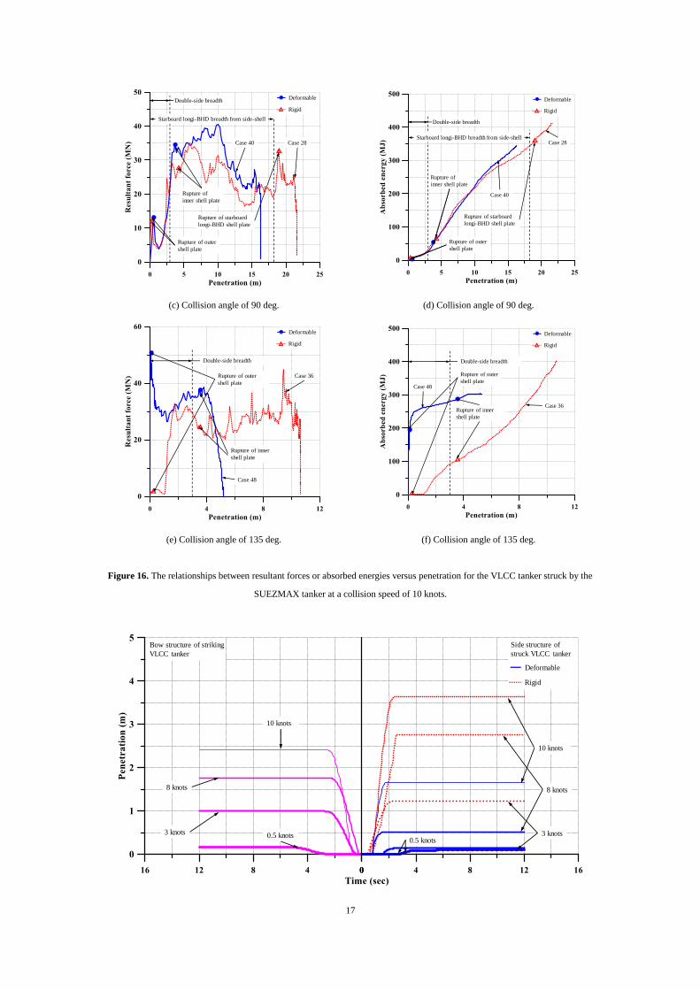
different collision cases. Figures 15 and 16 show the relationships between resultant forces or absorbed
energies versus penetration in conjunction with Figures 13 and 14. It is found that the differences
between the deformable and rigid bows are of significance in terms of the structural crashworthiness
associated with outer or inner hull rupture and maximum penetration. Considering that the deformable
bow model is more realistic and accurate, it is recommended that the rigid striking bow model applied
in the current industry practice should not be used for more refined computations of the structural
crashworthiness of ship-ship collisions.
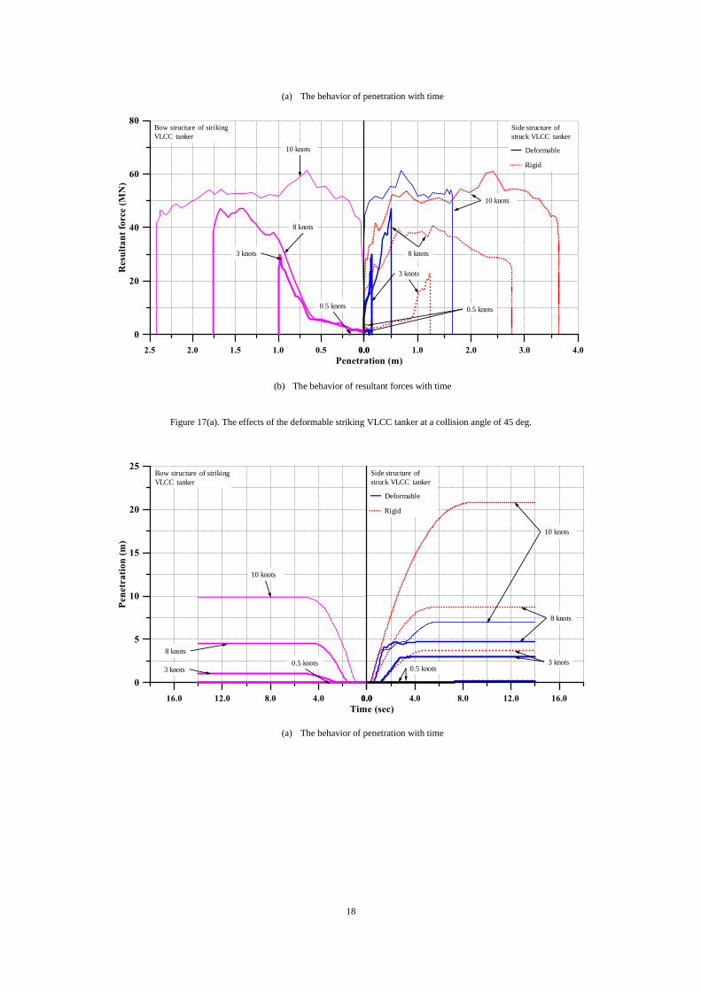
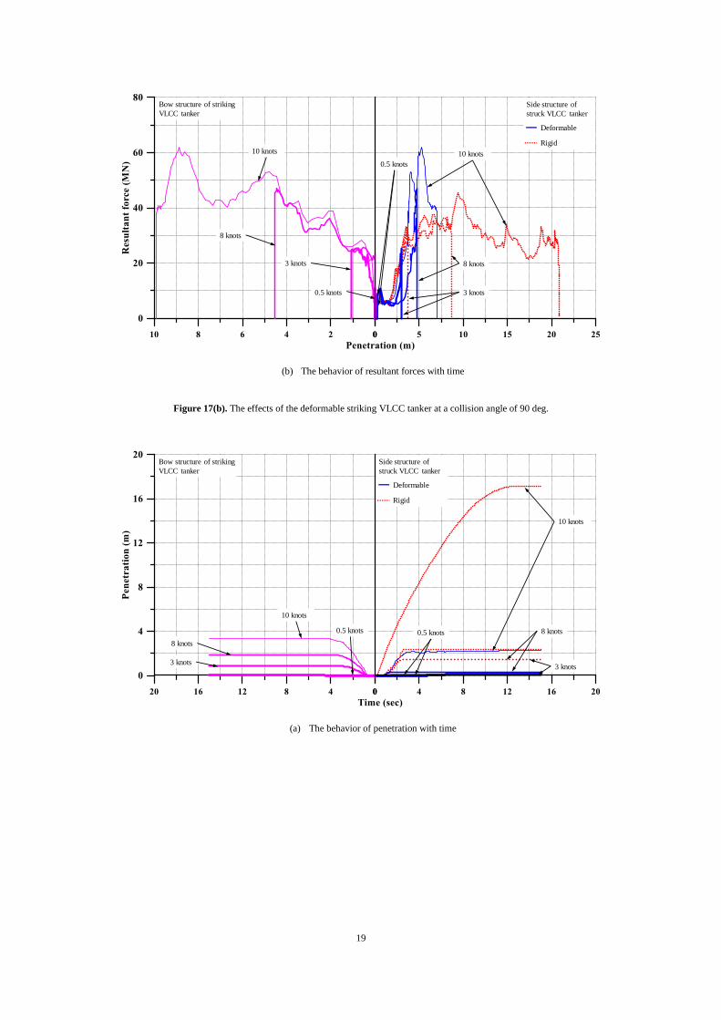
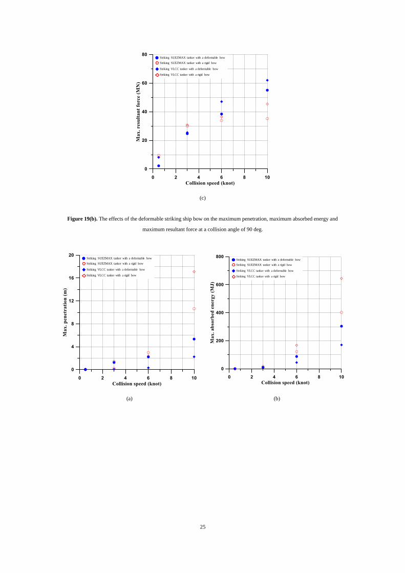
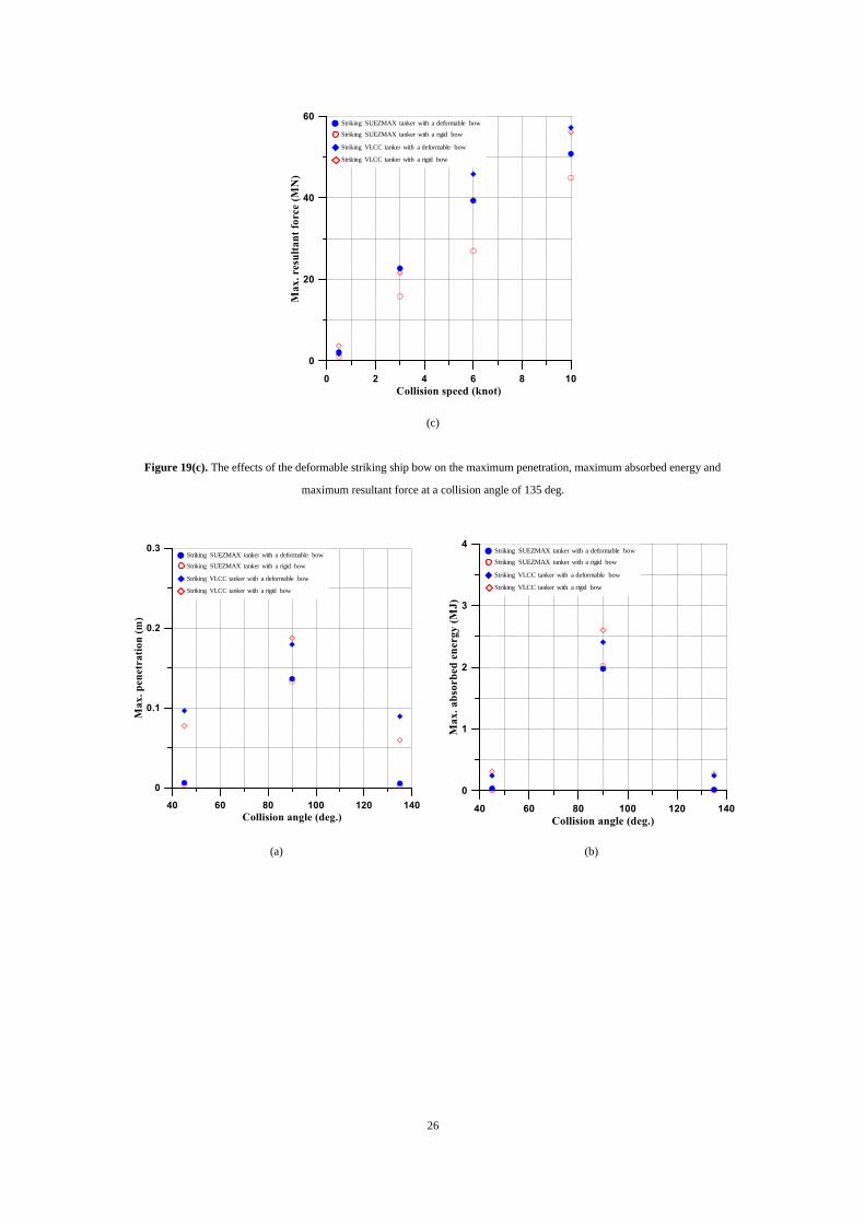
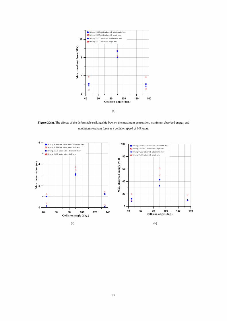
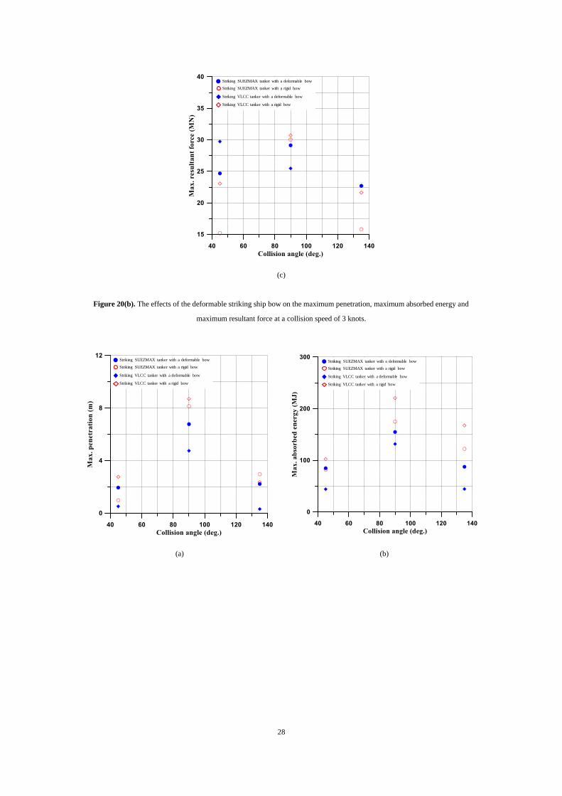
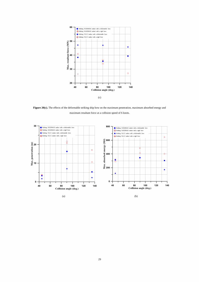
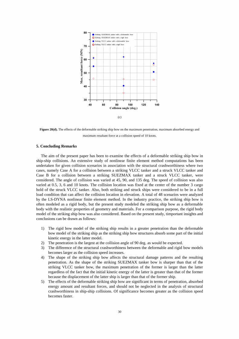
Figures 17 and 18 show the behavior of penetration or resultant forces with time for the striking
VLCC or SUEZMAX tanker. Figures 19 and 20 show the effects of the deformable striking ship bow
on the maximum penetration, maximum absorbed energy and maximum resultant forces with varying
angle or speed of collision. It is found from these results that the effects of the deformable striking ship
bow are of significance as the collision speed increases. It is obvious from these figures that the effects
of a deformable striking bow become more significant at a faster collision speed. Also, the maximum
penetration occurs at the collision angle of 90 deg. It is noted that the penetration tends be greater by
the striking SUEXMAX tanker than by the striking VLCC tanker regardless of the fact that the
displacement of the latter ship is larger than the former ship. This is because the bulbous bow of the
former ship is sharper than that of the latter ship. It is again obvious from these computations that the
deformable striking ship bow structures absorb some part of the initial kinetic energy of the collision as
they penetrate into the struck ship structures in contrast to the industry practice where all of the initial
kinetic energy is considered to be absorbed by the struck ship structures only because the striking ship
bow is modeled as a rigid body.
(a) Deformable bow at a collision angle of 45 deg. (b) Rigid bow at a collision angle of 45 deg.
14
(c) Deformable bow at a collision angle of 90 deg. (d) Rigid bow at a collision angle of 90 deg.
(e) Deformable bow at a collision angle of 135 deg. (f) Rigid bow at a collision angle of 135 deg.
Figure 13. Deformed shapes of struck VLCC tanker at around the tip of striking VLCC bow with a collision speed of 10 knots.
(a) Deformable bow at a collision angle of 45 deg. (b) Rigid bow at a collision angle of 45 deg.
15
(c) Deformable bow at a collision angle of 90 deg. (d) Rigid bow at a collision angle of 90 deg.
(e) Deformable bow at a collision angle of 135 deg. (f) Rigid bow at a collision angle of 135 deg.
Figure 14. Deformed shapes of struck VLCC tanker at around the tip of striking SUEXMAX bow with a collision speed of 10
knots.
(a) Collision angle of 45 deg. (b) Collision angle of 45 deg.
Rupture of
inner shell plate
Rupture of outer
shell plate
Double-side breadth
Deformable
Rigid
Case 8
Case 20
Rupture of inner
shell plate
Rupture of outer
shell plate
Double-side breadth
Case 8
Case 20
Deformable
Rigid
16
(c) Collision angle of 90 deg. (d) Collision angle of 90 deg.
(e) Collision angle of 135 deg. (f) Collision angle of 135 deg.
Figure 15. The relationships between resultant forces or absorbed energies versus penetration for the VLCC tanker struck by the
VLCC tanker at a collision speed of 10 knots.
(a) Collision angle of 45 deg. (b) Collision angle of 45 deg.
Rupture of inner
shell plate
Rupture of outer
shell plate
Double-side breadth
Rupture of starboard
longi-BHD shell plate
Starboard longi-BHD
breadth from side-shell
Deformable
Rigid
Case 4
Case 16
Rupture of inner
shell plate
Rupture of outer
shell plate
Double-side breadth
Rupture of starboard
longi-BHD shell plate
Starboard longi-BHD
breadth from side-shell
Deformable
Rigid
Case 4
Case 16
Rupture of inner
shell plate
Rupture of outer
shell plate
Double-side breadth
Deformable
Rigid
Case 12
Case 24
Rupture of inner
shell plate
Rupture of outer
shell plate
Double-side breadth
Deformable
Rigid
Case 12
Case 24
Rupture of inner
shell plate
Rupture of outer
shell plate
Double-side breadth
Deformable
Rigid
Case 32
Case 44
Rupture of inner
shell plate
Rupture of outer
shell plate
Double-side breadth
Case 32
Case 44
Deformable
Rigid
17
(c) Collision angle of 90 deg. (d) Collision angle of 90 deg.
(e) Collision angle of 135 deg. (f) Collision angle of 135 deg.
Figure 16. The relationships between resultant forces or absorbed energies versus penetration for the VLCC tanker struck by the
SUEZMAX tanker at a collision speed of 10 knots.
Rupture of
inner shell plate
Rupture of outer
shell plate
Double-side breadth
Rupture of starboard
longi-BHD shell plate
Starboard longi-BHD breadth from side-shell
Deformable
Rigid
Case 28Case 40
Rupture of
inner shell plate
Rupture of outer
shell plate
Double-side breadth
Rupture of starboard
longi-BHD shell plate
Starboard longi-BHD breadth from side-shell
Deformable
Rigid
Case 28
Case 40
Rupture of inner
shell plate
Rupture of outer
shell plate
Double-side breadth
Deformable
Rigid
Case 36
Case 48
Rupture of inner
shell plate
Rupture of outer
shell plate
Double-side breadth
Deformable
Rigid
Case 36
Case 48
Deformable
Rigid
Side structure of
struck VLCC tanker
Bow structure of striking
VLCC tanker
3 knots
10 knots
8 knots
0.5 knots
8 knots
10 knots
3 knots 0.5 knots
18
(a) The behavior of penetration with time
(b) The behavior of resultant forces with time
Figure 17(a). The effects of the deformable striking VLCC tanker at a collision angle of 45 deg.
(a) The behavior of penetration with time
Deformable
Rigid
Side structure of
struck VLCC tanker
Bow structure of striking
VLCC tanker
8 knots
10 knots
3 knots
0.5 knots
8 knots
10 knots
3 knots
0.5 knots
Deformable
Rigid
Side structure of
struck VLCC tanker
Bow structure of striking
VLCC tanker
3 knots
10 knots
8 knots
0.5 knots
8 knots
10 knots
3 knots0.5 knots
19
(b) The behavior of resultant forces with time
Figure 17(b). The effects of the deformable striking VLCC tanker at a collision angle of 90 deg.
(a) The behavior of penetration with time
Deformable
Rigid
Side structure of
struck VLCC tanker
Bow structure of striking
VLCC tanker
8 knots
10 knots
3 knots
0.5 knots
8 knots
10 knots
3 knots
0.5 knots
Deformable
Rigid
Side structure of
struck VLCC tanker
Bow structure of striking
VLCC tanker
3 knots
10 knots
8 knots0.5 knots
8 knots
10 knots
3 knots
0.5 knots
20
(b) The behavior of resultant forces with time
Figure 17(c). The effects of the deformable striking VLCC tanker at a collision angle of 135 deg.
(a) The behavior of penetration with time
Deformable
Rigid
Side structure of
struck VLCC tanker
Bow structure of striking
VLCC tanker
8 knots
10 knots
3 knots
0.5 knots
8 knots
10 knots
3 knots
0.5 knots
Deformable
Rigid
Side structure of
struck VLCC tankerBow structure of striking
SUEZMAX tanker
8 knots
10 knots
3 knots
0.5 knots
8 knots
10 knots
3 knots 0.5 knots
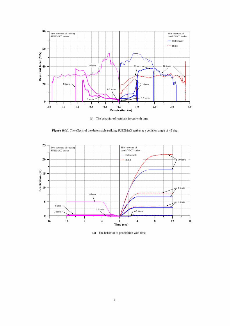
21
(b) The behavior of resultant forces with time
Figure 18(a). The effects of the deformable striking SUEZMAX tanker at a collision angle of 45 deg.
(a) The behavior of penetration with time
Deformable
Rigid
Side structure of
struck VLCC tanker
Bow structure of striking
SUEZMAX tanker
8 knots 10 knots
3 knots
0.5 knots
8 knots
10 knots
3 knots
0.5 knots
Deformable
Rigid
Side structure of
struck VLCC tanker
Bow structure of striking
SUEZMAX tanker
3 knots
10 knots
8 knots
0.5 knots
8 knots
10 knots
3 knots0.5 knots
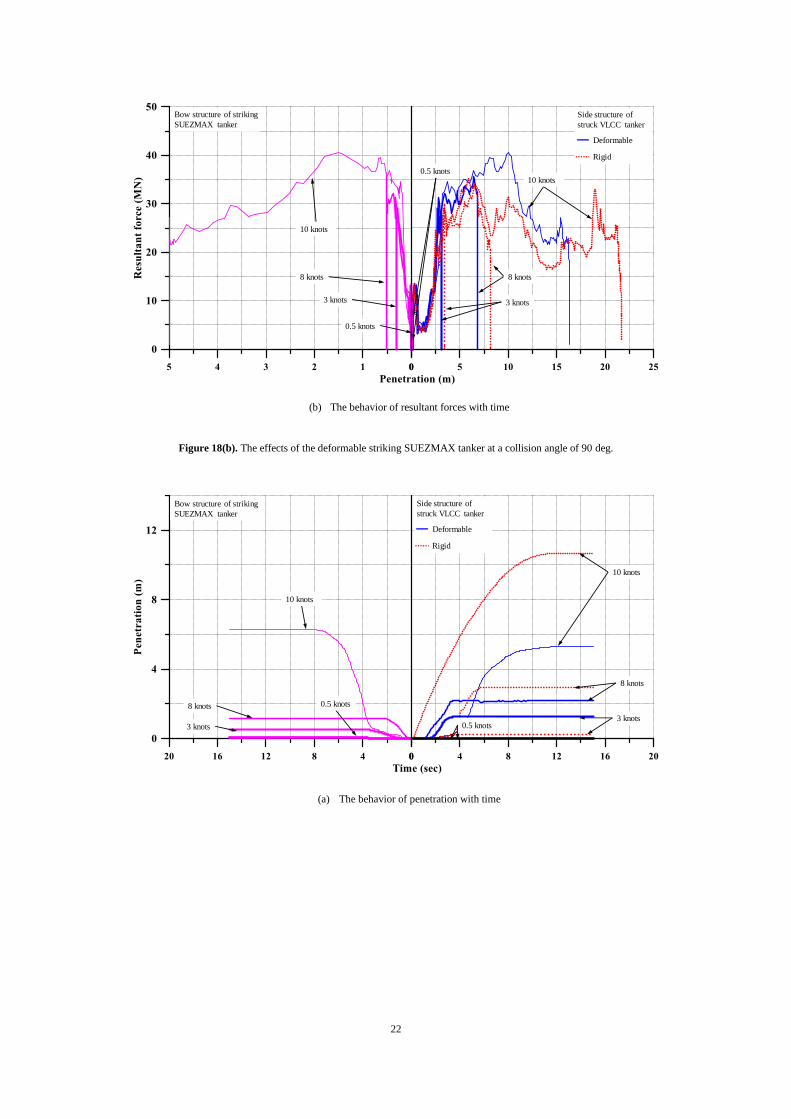
22
(b) The behavior of resultant forces with time
Figure 18(b). The effects of the deformable striking SUEZMAX tanker at a collision angle of 90 deg.
(a) The behavior of penetration with time
Deformable
Rigid
Side structure of
struck VLCC tanker
Bow structure of striking
SUEZMAX tanker
8 knots
10 knots
3 knots
0.5 knots
8 knots
10 knots
3 knots
0.5 knots
Deformable
Rigid
Side structure of
struck VLCC tanker
Bow structure of striking
SUEZMAX tanker
3 knots
10 knots
8 knots
0.5 knots
8 knots
10 knots
3 knots
0.5 knots
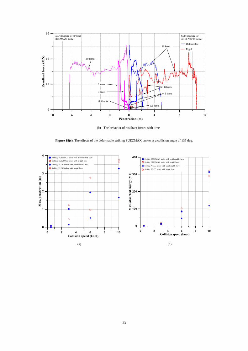
23
(b) The behavior of resultant forces with time
Figure 18(c). The effects of the deformable striking SUEZMAX tanker at a collision angle of 135 deg.
(a) (b)
Deformable
Rigid
Side structure of
struck VLCC tanker
Bow structure of striking
SUEZMAX tanker
8 knots
10 knots
3 knots
0.5 knots
8 knots
10 knots
3 knots
0.5 knots
Striking VLCC tanker with a rigid bow
Striking VLCC tanker with a deformable bow
Striking SUEZMAX tanker with a rigid bow
Striking SUEZMAX tanker with a deformable bow
Striking VLCC tanker with a rigid bow
Striking VLCC tanker with a deformable bow
Striking SUEZMAX tanker with a rigid bow
Striking SUEZMAX tanker with a deformable bow
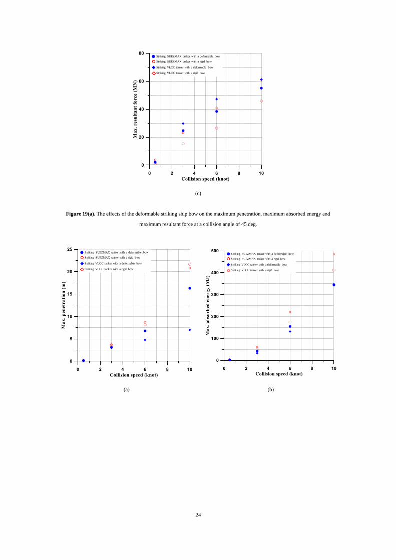
24
(c)
Figure 19(a). The effects of the deformable striking ship bow on the maximum penetration, maximum absorbed energy and
maximum resultant force at a collision angle of 45 deg.
(a) (b)
Striking VLCC tanker with a rigid bow
Striking VLCC tanker with a deformable bow
Striking SUEZMAX tanker with a rigid bow
Striking SUEZMAX tanker with a deformable bow
Striking VLCC tanker with a rigid bow
Striking VLCC tanker with a deformable bow
Striking SUEZMAX tanker with a rigid bow
Striking SUEZMAX tanker with a deformable bow
Striking VLCC tanker with a rigid bow
Striking VLCC tanker with a deformable bow
Striking SUEZMAX tanker with a rigid bow
Striking SUEZMAX tanker with a deformable bow
25
(c)
Figure 19(b). The effects of the deformable striking ship bow on the maximum penetration, maximum absorbed energy and
maximum resultant force at a collision angle of 90 deg.
(a) (b)
Striking VLCC tanker with a rigid bow
Striking VLCC tanker with a deformable bow
Striking SUEZMAX tanker with a rigid bow
Striking SUEZMAX tanker with a deformable bow
Striking VLCC tanker with a rigid bow
Striking VLCC tanker with a deformable bow
Striking SUEZMAX tanker with a rigid bow
Striking SUEZMAX tanker with a deformable bow
Striking VLCC tanker with a rigid bow
Striking VLCC tanker with a deformable bow
Striking SUEZMAX tanker with a rigid bow
Striking SUEZMAX tanker with a deformable bow
26
(c)
Figure 19(c). The effects of the deformable striking ship bow on the maximum penetration, maximum absorbed energy and
maximum resultant force at a collision angle of 135 deg.
(a) (b)
Striking VLCC tanker with a rigid bow
Striking VLCC tanker with a deformable bow
Striking SUEZMAX tanker with a rigid bow
Striking SUEZMAX tanker with a deformable bow
Striking VLCC tanker with a rigid bow
Striking VLCC tanker with a deformable bow
Striking SUEZMAX tanker with a rigid bow
Striking SUEZMAX tanker with a deformable bow
Striking VLCC tanker with a rigid bow
Striking VLCC tanker with a deformable bow
Striking SUEZMAX tanker with a rigid bow
Striking SUEZMAX tanker with a deformable bow
27
(c)
Figure 20(a). The effects of the deformable striking ship bow on the maximum penetration, maximum absorbed energy and
maximum resultant force at a collision speed of 0.5 knots.
(a) (b)
Striking VLCC tanker with a rigid bow
Striking VLCC tanker with a deformable bow
Striking SUEZMAX tanker with a rigid bow
Striking SUEZMAX tanker with a deformable bow
Striking VLCC tanker with a rigid bow
Striking VLCC tanker with a deformable bow
Striking SUEZMAX tanker with a rigid bow
Striking SUEZMAX tanker with a deformable bow
Striking VLCC tanker with a rigid bow
Striking VLCC tanker with a deformable bow
Striking SUEZMAX tanker with a rigid bow
Striking SUEZMAX tanker with a deformable bow
28
(c)
Figure 20(b). The effects of the deformable striking ship bow on the maximum penetration, maximum absorbed energy and
maximum resultant force at a collision speed of 3 knots.
(a) (b)
Striking VLCC tanker with a rigid bow
Striking VLCC tanker with a deformable bow
Striking SUEZMAX tanker with a rigid bow
Striking SUEZMAX tanker with a deformable bow
Striking VLCC tanker with a rigid bow
Striking VLCC tanker with a deformable bow
Striking SUEZMAX tanker with a rigid bow
Striking SUEZMAX tanker with a deformable bow
Striking VLCC tanker with a rigid bow
Striking VLCC tanker with a deformable bow
Striking SUEZMAX tanker with a rigid bow
Striking SUEZMAX tanker with a deformable bow
29
(c)
Figure 20(c). The effects of the deformable striking ship bow on the maximum penetration, maximum absorbed energy and
maximum resultant force at a collision speed of 6 knots.
(a) (b)
Striking VLCC tanker with a rigid bow
Striking VLCC tanker with a deformable bow
Striking SUEZMAX tanker with a rigid bow
Striking SUEZMAX tanker with a deformable bow
Striking VLCC tanker with a rigid bow
Striking VLCC tanker with a deformable bow
Striking SUEZMAX tanker with a rigid bow
Striking SUEZMAX tanker with a deformable bow
Striking VLCC tanker with a rigid bow
Striking VLCC tanker with a deformable bow
Striking SUEZMAX tanker with a rigid bow
Striking SUEZMAX tanker with a deformable bow
30
(c)
Figure 20(d). The effects of the deformable striking ship bow on the maximum penetration, maximum absorbed energy and
maximum resultant force at a collision speed of 10 knots.
5. Concluding Remarks
The aim of the present paper has been to examine the effects of a deformable striking ship bow in
ship-ship collisions. An extensive study of nonlinear finite element method computations has been
undertaken for given collision scenarios in association with the structural crashworthiness where two
cases, namely Case A for a collision between a striking VLCC tanker and a struck VLCC tanker and
Case B for a collision between a striking SUEZMAX tanker and a struck VLCC tanker, were
considered. The angle of collision was varied at 45, 90, and 135 deg. The speed of collision was also
varied at 0.5, 3, 6 and 10 knots. The collision location was fixed at the center of the number 3 cargo
hold of the struck VLCC tanker. Also, both striking and struck ships were considered to be in a full
load condition that can affect the collision location in elevation. A total of 48 scenarios were analyzed
by the LS-DYNA nonlinear finite element method. In the industry practice, the striking ship bow is
often modeled as a rigid body, but the present study modeled the striking ship bow as a deformable
body with the realistic properties of geometry and materials. For a comparison purpose, the rigid body
model of the striking ship bow was also considered. Based on the present study, timportant insights and
conclusions can be drawn as follows:
1) The rigid bow model of the striking ship results in a greater penetration than the deformable
bow model of the striking ship as the striking ship bow structures absorb some part of the initial
kinetic energy in the latter model.
2) The penetration is the largest at the collision angle of 90 deg. as would be expected.
3) The difference of the structural crashworthiness between the deformable and rigid bow models
becomes larger as the collision speed increases.
4) The shape of the striking ship bow affects the structural damage patterns and the resulting
penetration. As the shape of the striking SUEZMAX tanker bow is sharper than that of the
striking VLCC tanker bow, the maximum penetration of the former is larger than the latter
regardless of the fact that the initial kinetic energy of the latter is greater than that of the former
because the displacement of the latter ship is larger than that of the former ship.
5) The effects of the deformable striking ship bow are significant in terms of penetration, absorbed
energy amount and resultant forces, and should not be neglected in the analysis of structural
crashworthiness in ship-ship collisions. Of significance becomes greater as the collision speed
becomes faster.
Striking VLCC tanker with a rigid bow
Striking VLCC tanker with a deformable bow
Striking SUEZMAX tanker with a rigid bow
Striking SUEZMAX tanker with a deformable bow
31
Acknowledgements
The present study was undertaken at the Korea Ship and Offshore Research Institute at Pusan
National University which has been a Lloyd’s Register Foundation Research Centre of Excellence
since 2008.
References
Alsos HS. 2008. Ship grounding: analysis of ductile fracture, bottom damage and hull girder response
[PhD thesis]. Department of Marine Technology, Norwegian University of Science and
Technology, Trondheim, Norway.
Amdahl J. 1983. Energy absorption in ship-platform impacts [PhD thesis]. Department of Marine
Technology, Norwegian University of Science and Technology, Trondheim, Norway.
Ammerman DJ, Daidola JC. 1996. A comparison of methods for evaluating structure during ship
collision, Sandia National Labs., Albuquerque, New Mexico, USA
ANSYS/LS-DYNA. User’s manual for ANSYS/LS-DYNA, Version 14.5, ANSYS Inc., New York,
USA.
Bin S, Hu Z, Wang G. 2015. An analytical method for predicting the ship side structure response in
raked bow collisions. Marine Structure. 41: 288-311.
Buldgen L, Le Sourne H, Besnard N, Rigo P. 2012. Extension of the super-elements method to the
analysis of oblique collision between two ships. Marine Structure. 29: 22-57.
Cowper GR, Symonds PS. 1957. Strain-hardening and strain-rate effects in the impact loading of
cantilever beams. Technical Report No. 28, Division of Applied Mathematics, Brown University,
Providence, USA.
Ehlers S, Guird M, Kubiczek J, Hoderath A, Sander F, Sopper R, Charbonnier P, Marhem M, Darie I,
von Selle H, Peschmann J, Bendfeldt P. 2016. Experimental and numerical analysis of a membrane
cargo containment system for liquefied natural gas. Ships and Offshore Structures. 12(S1):
S257-S267.
Ehlers S, Tabri K, Romanoff J, Varsta P. 2010. Numerical and experimental investigation on the
collision resistance of the X-core structure. Ships and Offshore Structures. 7(1): 21-29.
Faisal M, Noh SH, Kawsar MRU, Youssef SAM, Seo JK, Ha YC, Paik JK. 2016. Rapid hull collapse
strength calculations of double hull oil tankers after collisions. Ships and Offshore Structures.
12(5): 624-639.
Ferry M, Le Sourne H, Besnier F. 2002. MCOL-Theoretical Manual. Technical Report 01-52, French
Shipbuilding Research Institute, Nantes.
Hallquist JO. 2010. LS-DYNA 3D Theory manual, Livermore Software Technology Corporation, CA,
USA.
Haris S, Amdahl J. 2011. An analytical model to assess a ship side during a collision. Ship and
Offshore Structures. 7(4): 431-448.
Haris S, Amdahl J. 2013. Analysis of ship-ship collision damage accounting for bow and side
deformation interaction. Marine Structures. 32: 18-48.
Hogstrom P, Ringsberg JW. An extensive study of a ship’s survivability after collision – A parameter
study of material characteristics, non-linear FEA and damage stability analyses. Marine Structures.
27: 1-28.
Hong L. 2008. Simplified analysis and design of ships subjected to collision and grounding, Norwegian
University of Science and Technology, Trondheim, Norway.
32
Hong L. 2009. Simplified analysis and design of ships subjected to collision and grounding [PhD
thesis]. Department of Marine Technology, Norwegian University of Science and Technology,
Trondheim, Norway.
ISSC. 2003. Committee V.3: collision and grounding, Proceedings of 15th International Ship and
Offshore Structures Congress, San Diego, USA, 11-15 August 2003.
ISSC. 2012. Committee V.1: Damage assessment following accidents, International Ship and Offshore
Structures Congress (ISSC), Rostock, Germany, 10-13 September 2012.
Karlsson UB. 2009. Improved collision safety of ships by an intrusion-tolerant inner side shell. Marine
Technology. 46: 165-173.
Kim YS, Youssef SAM, Ince ST, Kim SJ, Seo JK, Kim BJ, Ha YC, Paik JK. 2015. Environmental
consequences associated with collisions involving double hull oil tanker. Ship and Offshore
Structures. 10(5): 479–487.
Kitamura O. 2000. Buffer bow design for the improved safety of ships. Ship Structure Symposium,
Virginia, USA.
Ko YG, Kim SJ, Sohn JM, Paik JK. 2017. A practical method to determine the dynamic fracture strain
in nonlinear finite element method computations of ship-ship collisions. Submitted for publication
in a journal.
Kuroiwa T, Kawamoto Y, Kusuba S, Stillman, D. 1995. Numerical Simulation of Collision and
Grounding of Ships. Proceedings of MARIENV’95, 66-70.
Kuroiwa T. 1996. Numerical simulation of actual collision & grounding accidents, Proceedings of
International Conference on Design and Methodologies for Collision and Grounding Protection of
Ships, San Francisco, USA.
Le Source H, Couty N, Besnier F, Kammerer C, Legavre H. 2003. LS-DYNA applications in
shipbuilding, Proceedings of 4th European LS-DYNA Users Conference. 1-16.
Liu B, Villavicenco R, Soares CG. 2013. Experimental and numerical plastic response and failure of
laterally impacted rectangular plates. Journal of Offshore Mechanics and Arctic Engineering. 135:
1-7.
Montewka J, Goerlandt F, Ehlers S, Kunjala P, Erceg S, Polic D, Klanac A, Hinz T, Tabri K. 2012.
Sustainable Maritime Transportation and Exploitation of Sea Resources. Taylor & Francis, London,
UK.
Ozguc O, Das PK, Barltrop N. 2005. A comparative study on the structural integrity of single and
double side skin bulk carriers under collision damage. Marine Structures. 18: 511-547.
Parunov J, Rudan S, Corak M. 2016. Ultimate hull-girder-strength-based reliability of a double-hull oil
tanker after collision in the Adriatic Sea. Ship and Offshore Structures. 12(S1): S55-S67.
Paik JK. 2007a. Practical techniques for finite element modeling to simulate structural crashworthiness
in ship collisions and grounding (Part I: Theory). Ships and Offshore Structures. 2(1): 69-80.
Paik JK. 2007b. Practical techniques for finite element modeling to simulate structural crashworthiness
in ship collisions and grounding (Part II: Verification). Ships and Offshore Structures. 2(1): 81-86.
Paik JK, Thayamballi AK. 2003. Ultimate limit state design of steel plated structures. Wiley,
Chichester.
Paik JK, Thayamballi AK. 2007. Ship-shaped offshore installation: design, building and operation,
Cambridge University Press, Cambridge, London.
Paik JK, Park JH, Samuelides E. 2009. Collision accidental limit states performance of double hull oil
tanker structures: Pre-CSR versus CSR designs. Marine Technology. 46: 183-191.
33
Pedersen PT. 1993. Ship impacts: Bow collision. International Journal of Impact Engineering. 13:
163-187.
Pedersen PT, Zhang S. 1998. On Impact Mechanics in Ship Collisions. Journal of Marine Structures.
11(10): 429-449.
Sajdak J, Brown A. 2004. Modeling longitudinal damage in ship collisions, Technical Report No.
SSC-437, Ship Structural Committee, Washington D.C, USA.
Simonsen BC. 1997. Mechanics of ship grounding [PhD thesis]. Department of Naval Architecture and
Offshore Engineering, Technical University of Denmark, Lyngby, Denmark.
Storheim M, Amdahl J. 2014. Design of offshore structures against accidental ship collisions. Marine
Structures. 37: 135-172.
Storheim M, Amdahl J. 2015. On the sensitivity to work hardening and strain-rate effects in nonlinear
FEM analysis of ship collisions. Ship and Offshore Structures. 12(1): 100-115.
Storheim M, Alsos HS, Hopperstad OS, Amdahl J. 2015. A damage-based failure model for coarsely
meshed shell structures. International Journal of Impact Engineering. 83: 59–75.
Tavakoli MT, Amdahl J, Leira BJ. 2010. Analytical and numerical modelling of oil spill from a side
tank with collision damage. Ship and Offshore Structures. 7(1): 73-86.
Tornqvist R. 2003. Design of crashworthy ship structures [PhD thesis]. Department of Naval
Architecture and Offshore Engineering. Technical University of Denmark, Lyngby, Denmark.
Urban J. 2003. Crushing and fracture of lightweight structures [PhD thesis]. Department of Mechanical
Engineering, Technical University of Denmark, Lyngby, Denmark.
Villavicenco R, Kim YH, Cho SR, Guedes Soares C. 2013. Deformation process of web girders in
small-scale tanker double hull structures subjected to lateral impact. Marine structures. 32: 84-112.
Wisniewski K, Kolakowski P. 2002. The effect of selected parameters on ship collision results by
dynamic FE simulations. Finite Elements in Analysis and Design. 39: 985-1006.
Yamada Y, Endo H. 2008. Experimental and numerical study on the collapse strength of the bulbous
bow structure in oblique collision. Marine Technology. 45:42–53.
Youssef SAM, Faisal M, Seo JK, Kim BJ, Ha YC, Kim DK, Paik JK, Cheng F, Kim MS. 2014.
Assessing the risk of ship hull collapse due to collision. Ship and Offshore Structures. 11(4):
335-350.
Youssef SAM, Noh SH, Paik JK. 2017. A new method for assessing the safety of ships damaged by
collisions. Ship and Offshore Structures. (http://dx.doi.org/10.1080/17445302.2017.1285679)
Zhang S. 1999. The mechanics of ship collisions [PhD thesis]. Department of Naval Architecture and
Offshore Engineering, Technical University of Denmark, Lyngby, Denmark.
Zhang S, Villavicencio R, Zhu L, Pedersen PT. 2016. Impact mechanics of ship collisions and
validations with experimental results. Marine structures. 52: 69–81.
Zheng Y, Aksu D, Vassalos, Tuzcu C. 2007. Study on side structure resistance to ship-ship collision.
Ship and Offshore Structures. 2(3): 273–293.


![Vega: Nonlinear FEM Deformable Object Simulatorrun.usc.edu/vega/SinSchroederBarbic2012.pdf · Vega: Nonlinear FEM Deformable Object Simulator ... (CalculiX [DW]) deformable ... J](https://img.pdfslide.net/doc/110x75/5aecb8f27f8b9a3b2e8f8865/vega-nonlinear-fem-deformable-object-nonlinear-fem-deformable-object-simulator.jpg)