Embed Size (px)
Citation preview
Brasil Internship report : the helicalresonator
Contribution to strontium cavityand lattice experiments
Author:Djeylan Aktas
Supervisors:Philippe Courteille
Michael HolynskiPaulo Hisao Moriya
October 18, 2013
Contents1 Introduction 2
2 The compensation coils 2
3 The Steck laser 3
4 Why an helical resonator? 34.1 The apparatus . . . . . . . . . . . . . . . . . . . . . . . . . . . . 44.2 Results and discussions . . . . . . . . . . . . . . . . . . . . . . . 6
5 Conclusions 7
Remerciements
First and foremost I’d like to thanks Philippe who raised hell to give me thechance to participate to this internship, indeed, since my application was lostin translation by computers between France and Brasil he had to find a way toget me funding to come anyway because I was considering of maybe doing aPhD in Brasil. I also like to thanks everyone from the optical group for givingme such a warm welcome. It’s not an exhaustive list but I’d like to mentionRomain Bachelard my french compatriot who showed me the ropes of how togo out in Sao Carlos. I’m thanks full to Michael Holynski and Paulo HisaoMoriya the two experimentalists that I worked with everyday. I don’t know
what I would have done without Paulo translator skills, he was a huge help toguide me along to realize my projects. I also learned a lot from my discussionswith Mike and working all together with the students in this lab was not onlypleasant but also very well organized. That’s one of the point I’d like to stressbecause it’s not easy to find a team that work well together and has a well
thought and efficient process to welcome a new team member even for a shortperiod of time.
AbstractThe main goal of this report is to leave a written trace of the work
accomplish on the helical resonator project. During my internship I’veparticipated to several projects : designing and putting in place compen-sation coils on the experiment, premisses for the build of an ultra-stablelaser and several day to day tasks to help the strontium lattice experi-ment in progress. The helical resonator in question is meant for the nextexperiment where it’s suppose to act as a transformer and provide thenecessary voltage to supply an EOM. For the input we intend to use a20 MHz signal to create side-bands which combine with a cavity provideus all the tools for a PDH scheme. The reflected signal coming from thecavity is used to get an error signal to feed a servo-lock loop in order tostabilize our laser.
1
1 IntroductionIntegrating a new lab is never easy and furthermore, when you know you will
spend a short amount of time among a team of experimentalists, finding theright project that will allow you to contribute in a meaning full matter is not aneasy decision either. One of the main reasons for that is simple to understand:to work in a lab you have to learn ways of the lab so you kind of disturbing theactual workers, and while they’re teaching you they’re not working anymore.Anyway after a short period of learning my way around the lab we decided Iwill try to find a way to contribute to the advancement of the next experiment(the strontium cavity project) by helping putting in place an essential part ofthe locking scheme : the EOM that generate the side-bands for the error signal.The first step consisted in aligning a Fabry-Pérot in order to analyse the signalat the output of the EOM. The lack of side-bands, because we were not able toprovide sufficiently high voltage in the EOM, gave rise to the idea of buildingour own transformer.I also spend some time learning about the current experiment (strontium lattice)and we decided it would be helpful to have compensation coils to work with soI design and build three rectangular pairs of coils by winding some copper wirestogether. Finally while I was waiting for the mechanical workshop to finishbuilding a much needed cylinder in copper for my helical resonator, I startedchecking, ordering and listing all the parts needed to build a replicate of theSteck laser for the strontium cavity experiment.
2 The compensation coilsBuilding compensation coils is pretty straight forward. Indeed one only need
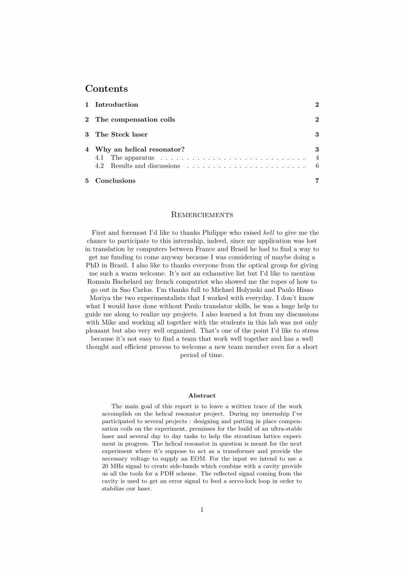
to thing about the number of turns needed to reach a desired magnetic fieldand the more turns you use, the less current you need to get it. Consideringthe fact that we wanted to put those coils in place while disturbing as little aspossible the experiment, I decided to minimize the number of turns. Since Iknew we will be using power supply capable of at least 10 A and that we willneed to obtain fields in the order of 1 Gauss, I chose accordingly after runningsome quick simulations. Of course after making the first pair, we checked thatwith an Helmoltz configuration we could measure the predicted magnetic fieldand it was indeed the case. The most difficult part of this task was to manageto put in place these coils and it took 2 days of work without counting the weekof re-alignment that took place after that.
Figure 1: Compensation coils picture installed around the science chamber.
2
3 The Steck laserAnother project I participated in was the construction of a new ultra-stable
laser following the recommendation of this paper [1]. After studying the articleand the manual put in place to explain the assembly process, I started to listwhat we needed to build our own version of this laser. I also checked that piecesprovided by the mechanical workshop were properly fabricated and fitted ourspecifications. When the optics ordered at Thorlabs finally arrived I had thetime to check and characterize all of the six laser diodes we received in term ofwavelength and power so we could choose the most appropriate ones to buildour two lasers. But that’s all I could accomplish on this project in the twomonth I stayed at the IFSC.
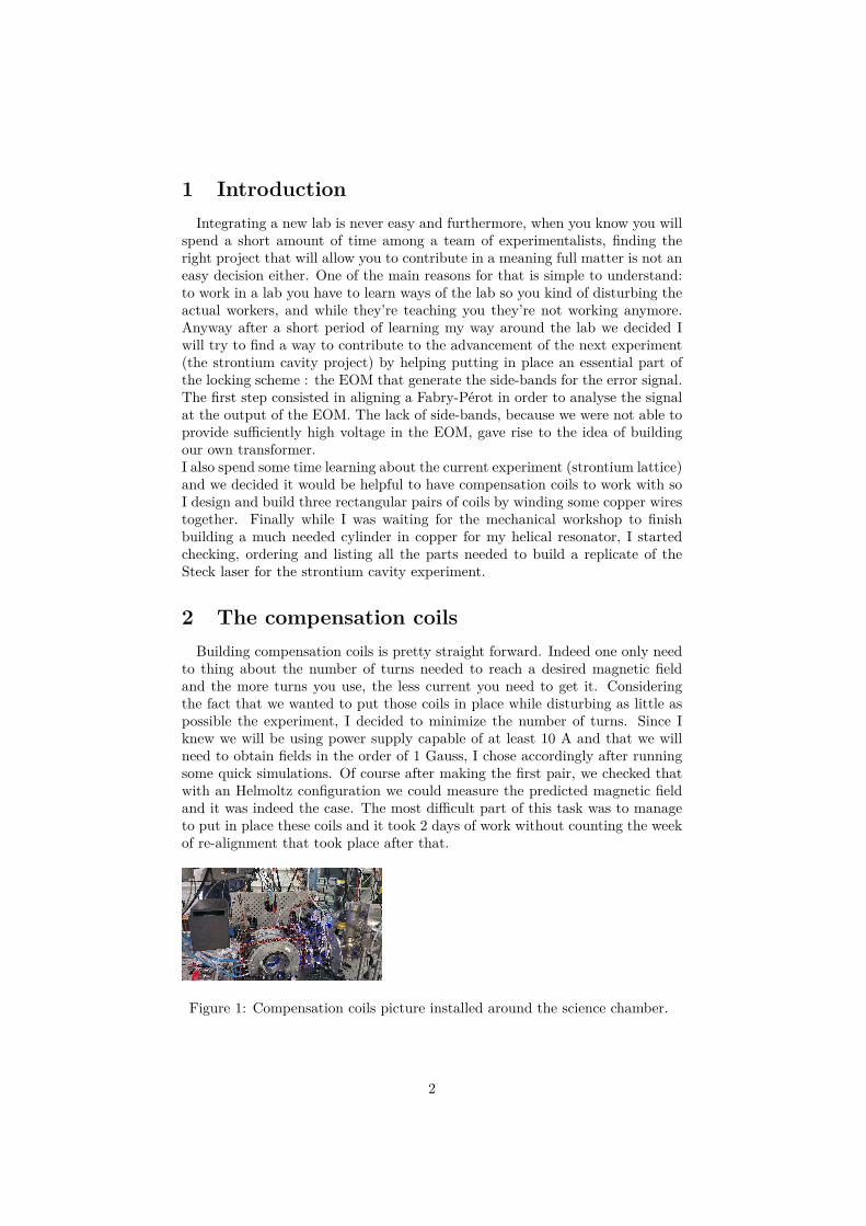
4 Why an helical resonator?As I mention in the introduction there was a need for a transformer to supplyenough voltage to the EOM on my main project.
Figure 2: Layout for analysis of the EOM output: a part of the output of thered laser (dashed lines represent the optics omitted to simplify the figure) at689 nm is used, after going through an EOM supplied with enough voltage toinduce a phase shift we analyse the light with a Fabry-Pérot.
At first, I tried several ways to obtain the necessary voltage to supply theEOM at the desired frequency of 20 MHz. Either a standard transformer circuit(2 separated coils) or an auto-transformer (only one coil and a part of it isactually used as a secondary coil) failed to give enough gain to observe side-bands when plugged into the EOM.One of the first task was to check if the EOM possessed indeed the indicatedcapacitance and that it didn’t act as a resistor also. As reported in my lab bookwe could verify that the capacitance of the order of ∼ 100 pF and no resistancecould be measured.We then decided to build an helical resonator like in [2] to get a better impedancematching and high factor quality for our transformer. Near to the end of myinternship the workshop finished the main element of my design for an helicalresonator so I was able to finish building it in time.
3
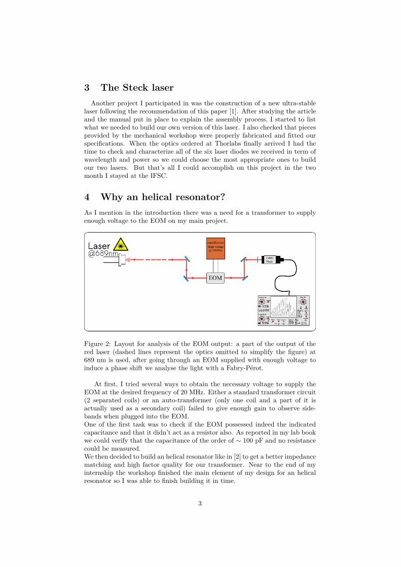
4.1 The apparatusThe principle idea of an helical resonator is to place the two coils in a cylindri-
cal conductive cavity in order to reach high quality factor in a transformer. Alsothis scheme allow for better impedance matching through the tunable windingpitch of the antenna (the secondary coil).
Figure 3: Helical resonator schematic.
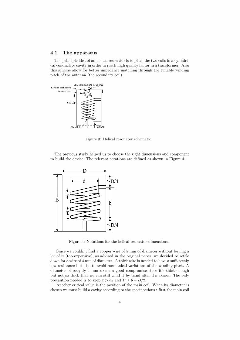
The previous study helped us to choose the right dimensions and componentto build the device. The relevant cotations are defined as shown in Figure 4.
Figure 4: Notations for the helical resonator dimensions.
Since we couldn’t find a copper wire of 5 mm of diameter without buying alot of it (too expensive), as advised in the original paper, we decided to settledown for a wire of 4 mm of diameter. A thick wire is needed to have a sufficientlylow resistance but also to avoid mechanical variations of the winding pitch. Adiameter of roughly 4 mm seems a good compromise since it’s thick enoughbut not so thick that we can still wind it by hand after it’s akneel. The onlyprecaution needed is to keep τ > d0 and B ≥ b+D/2.
Another critical value is the position of the main coil. When its diameter ischosen we must build a cavity according to the specifications : first the main coil
4
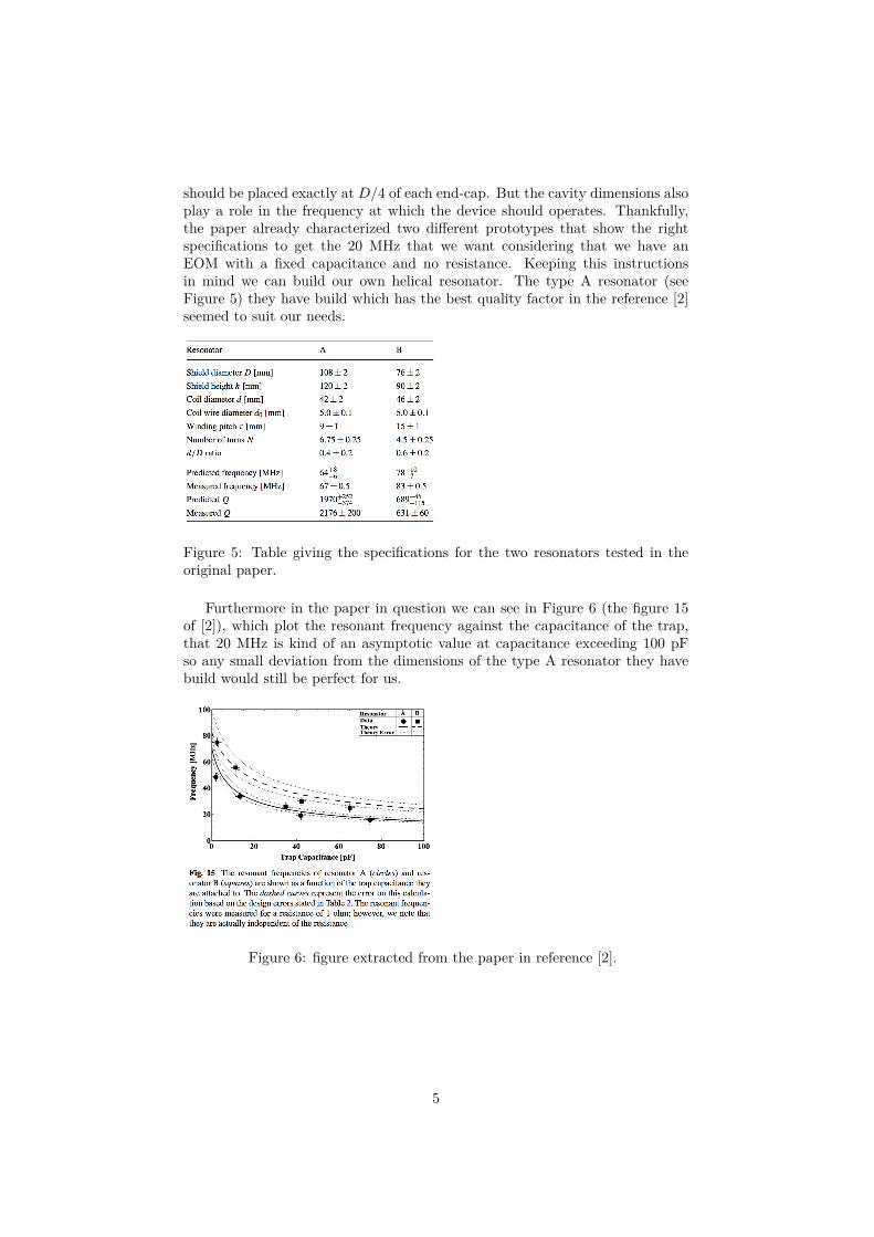
should be placed exactly at D/4 of each end-cap. But the cavity dimensions alsoplay a role in the frequency at which the device should operates. Thankfully,the paper already characterized two different prototypes that show the rightspecifications to get the 20 MHz that we want considering that we have anEOM with a fixed capacitance and no resistance. Keeping this instructionsin mind we can build our own helical resonator. The type A resonator (seeFigure 5) they have build which has the best quality factor in the reference [2]seemed to suit our needs.
Figure 5: Table giving the specifications for the two resonators tested in theoriginal paper.
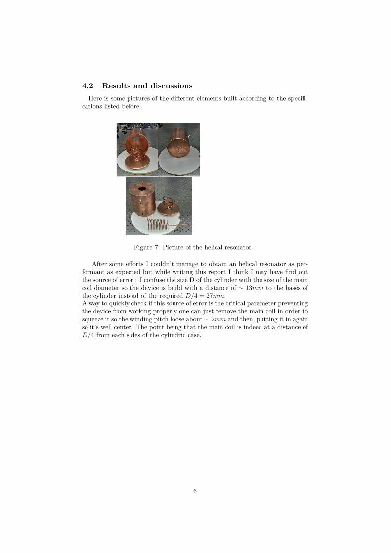
Furthermore in the paper in question we can see in Figure 6 (the figure 15of [2]), which plot the resonant frequency against the capacitance of the trap,that 20 MHz is kind of an asymptotic value at capacitance exceeding 100 pFso any small deviation from the dimensions of the type A resonator they havebuild would still be perfect for us.
Figure 6: figure extracted from the paper in reference [2].
5
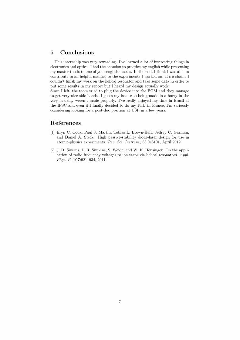
4.2 Results and discussionsHere is some pictures of the different elements built according to the specifi-
cations listed before:
Figure 7: Picture of the helical resonator.
After some efforts I couldn’t manage to obtain an helical resonator as per-formant as expected but while writing this report I think I may have find outthe source of error : I confuse the size D of the cylinder with the size of the maincoil diameter so the device is build with a distance of ∼ 13mm to the bases ofthe cylinder instead of the required D/4 = 27mm.A way to quickly check if this source of error is the critical parameter preventingthe device from working properly one can just remove the main coil in order tosqueeze it so the winding pitch loose about ∼ 2mm and then, putting it in againso it’s well center. The point being that the main coil is indeed at a distance ofD/4 from each sides of the cylindric case.
6
5 ConclusionsThis internship was very rewarding. I’ve learned a lot of interesting things in
electronics and optics. I had the occasion to practice my english while presentingmy master thesis to one of your english classes. In the end, I think I was able tocontribute in an helpful manner to the experiments I worked on. It’s a shame Icouldn’t finish my work on the helical resonator and take some data in order toput some results in my report but I heard my design actually work.Since I left, the team tried to plug the device into the EOM and they manageto get very nice side-bands. I guess my last tests being made in a hurry in thevery last day weren’t made properly. I’ve really enjoyed my time in Brasil atthe IFSC and even if I finally decided to do my PhD in France, I’m seriouslyconsidering looking for a post-doc position at USP in a few years.
References[1] Eryn C. Cook, Paul J. Martin, Tobias L. Brown-Heft, Jeffrey C. Garman,
and Daniel A. Steck. High passive-stability diode-laser design for use inatomic-physics experiments. Rev. Sci. Instrum., 83:043101, April 2012.
[2] J. D. Siverns, L. R. Simkins, S. Weidt, and W. K. Hensinger. On the appli-cation of radio frequency voltages to ion traps via helical resonators. Appl.Phys. B, 107:921–934, 2011.
7