Embed Size (px)
Citation preview

1
Contribution to the design of road pavements in Cape Verde
Sandra Fonseca
Abstract: Over the past five years, Cape Verde has spent about 147 million dollars a year, almost 8
percent of gross domestic product (GDP) on infrastructures, one of the highest levels of investment in this
sector found in the African continent. Expenses are mainly directed to capital expenditures with the
resources dedicated to the support of the transports activity being especially high.
This thesis aims to evaluate new paving technologies to be implemented in Cape Verde, analyzing first of
all, the solutions implemented to date, studying aspects such as traffic and its temporal prediction and the
materials currently used in its design, comparing in terms of direct current cost these solutions and the
new solutions deemed adequate to be used in the country.. Some of Cape Verde road projects were
analysed, aiming to assess the current state of the country, addressing the paving technology employed, in
particular the flexible structure pavements with asphalt concrete wearing course and basalt stone
pavements (paving solution most used in Cape Verde). In the second part of this thesis it is analysed,
based on traffic studies, foundation analysis and on the catalogue of SATTC, possible flexible pavements
structures to implement in Cape Verde. The AUSTROADS and Shell methods are used to validate the
pavement structures. Finally it is made a comparison in terms of construction costs between the most used
pavement solution that is the traditional flexible pavement and new pavement solutions proposed in this
dissertation, namely pavements with soil stabilized with cement.
Keywords: Pavements, Paving Technologies, Granular materials, Materials stabilized with cement,
Performance
1. Introduction
Since the second half of the twentieth century
there has been a growing evolution in the study of
the peculiarities of tropical soils as road
construction materials. Due to its extension
worldwide, it is important to assess the existing
soil as road paving material, which can provide
significant economic and technical advantages
when compared to other materials traditionally
used in pavements.
Thus, it is important to evaluate the possibility
of using local materials in the construction of road
pavements in order to contribute to more effective
solutions that respond to particular aspects as the
climate, the traffic intensity, the available
resources and the needs of each country.
It is in this context that the need to implement
other materials in roads infrastructures such as
asphalt, soil stabilizers, namely cement, instead of
other materials commonly used in Cape Verde,
such as the basalt pavement .
This thesis is a contribution to increasing the
knowledge about technologies for road paving in
Cape Verde, aiming to present to the country
solutions and alternative ways to solve problems
and evaluating if these alternatives are sustainable
in terms of cost and of existing technologies in the
country.
2. Characterization and pavement
construction technologies used in
Cape Verde
2.1 Initial consideration Cape Verde, as a small developing archipelago,
suffers from a natural vulnerability due to its small
size, geographic dispersion and isolation. This is a
disadvantage of the islands regarding the spatial
planning and development.. The natural beauty of
the islands as well as the hot and dry climate led
this nation to invest in the tourism sector as a base
for the development of the country. Thus, tourism
contributes to the overall socio-economic
development and enhances the creation of
numerous infrastructures, including the road
network. However, in the current context of global
economic crisis, the economic dependence on
foreign countries, aggravated by limited natural
resources, put the economy in a fragile position,
compromising the progress and, consequently, the
development potential that the country has
demonstrated in recent years.

2
The improvement of accessibility and mobility
has been key factors in the development of the
country. This has been possible with the increasing
development of construction technologies and
constant research of materials, methods and studies
of how to optimize the road pavements taking into
account the particularities of the country, the as
the road traffic, the weather and the availability of
materials.
In the figure 2.1 is possible to see the extension of
existing national roads in each of Cape Verde
islands.
Figure 2. 1: National road extension
As it is possible to see in the chart the bigger
islands (Santiago, Santo Antao and Fogo) have
greater extensions of roads, which was already
expected.
For representing the bigger islands, they require
greater lengths of roads to meet their needs and
reach all the villages, towns and populations.
Furthermore there is a large discrepancy in the use
of funding between the various islands. Santiago,
being the island where the country's capital, has
benefited more than the other islands, and
therefore one whose development is greater,
especially in terms of transport infrastructure.
In the figure 2.2 it is presented the road extension
by type of pavement.
Figure 2. 2: Extension of National roads by type
2.2 Flexible pavements and materials
used in its design
The flexible pavements have been, in recent years,
the main option as paving solution of most of the
roads of the national road network in Cape Verde.
The introduction of the asphalt concrete in Cape
Verde began on Sal Island in the nineteenth
century. The road that extends from the only
international airport at the time, Amilcar Cabral
Airport and the main village, village of Asparagus
consisted simply on 1 carriageway with 2, one in
each direction. This was important for the
economic development of the country.
Only many years later, it was possible to observe
the growth on the development of roads in Cape
Verde based on asphalt concrete.
2.2.1. Structure of a flexible pavement
In the figure 2.3 below, it is possible to see the
typical structure of a flexible pavement and its
composition.
0
100 000
200 000
300 000
400 000
San
to A
ntã
o
São
Vic
en
te
São
Nic
ola
u
Sal
Bo
a V
ista
Mai
o
San
tiag
o
Fogo
Bra
va
National road extension(m):
Extensão Estradas…
375.977;
36%
595.316;
57%
7.409; 1%
67.737; 6%
Extension of National roads by type:
Extensão BB (m)
Extensão Pedra(m)Extensão Betão -LAS (m)Extensão TerraBatida (m)

3
Figure 2. 3: Schematic section of a flexible pavement
(Antunes et al, 2006)
Two recent road projects with greather impact in
terms of economic growth were analyzed to
examine the technologies and materials used in the
pavements(flexible pavements), namely:
• Rehabilitation of the road between Lém Ferreira
and the port of Praia - Santiago Island
• Design of the road between the city of Praiaand
Cidade Velha.
2.2.1.1 Design and rehabilitation of the road
between Lém Ferreira and Port of Praia-
Santiago Island
Figure 2.4: Extension of the road between Lém Ferreira
and Port of Praia
This road existed already, and it was a basalt
stone pavement.
On this rehabilitation, two solutions were used.
On the first solution, the existing pavement was
totally removed and replaced with a new flexible
pavement. On the second solution the existing
pavement was reused as a base for new asphalt
concrete wearing course..
For the first solution, the existing ground was
excavated, regraded and compacted. For the sub-
base and base layers a 20 cm layer crushed
aggregate (coarse aggregate) were used. On top of
the base layer a prime layer was used to provide
adherence to the wearing course. For wearing
course a 5 cm thick asphalt concrete was used.
Figure 2. 5: Cross section of the new solution adopted
The second solution, shown in Figure 2.6 below,
differs from the previous because the existing was
not removed. It was reused as base for the wearing
course. This solution does not consider the sub-
base and base layers..
Figure 2. 6: Cross section of the second situation of
rehabilitation of the road section Lem Ferreira- Port of
Praia
2.2.2. Design of the link road of between the
city of Praia City link and Cidade Velha
This is a road project with 10 km of extension,
starting at Km 0 + 000 (at São Martinho junction)
and ending at Km 10 + 300 right at
Caniço (Cidade Velha). The road works started in
March 2012 and and the road open to traffic in
July 2013.
Figure 2. 7: Profile Cross Type – Cidade Velha road
section
After the completion of the ground investigation
the design software Ecoroute was used to
determine the pavement structure. The following
structure was adopted:
- Base layer of asphalt concrete 0/10 (6 cm)
- Base layer of crushed gravel 0/20 (20 cm)
- Layer Foundation in gravel crushed 0 / 31.5
(22 cm)
4
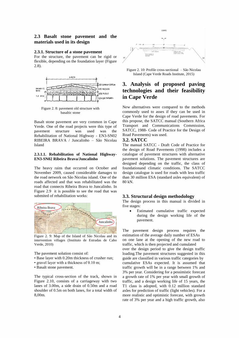
2.3 Basalt stone pavement and the
materials used in its design
2.3.1. Structure of a stone pavement For the structure, the pavement can be rigid or
flexible, depending on the foundation layer (Figure
2.8).
Basalt stone pavement are very common in Cape
Verde. One of the road projects were this type of
pavement structure was used was the
Rehabilitation of National Highway - EN3-SN02
RIBEIRA BRAVA / Juncalinho – São Nicolau
Island
2.3.1.1. Rehabilitation of National Highway-
EN3-SN02 Ribeira Brava/Juncalinho
The heavy rains that occurred on October and
November 2009, caused considerable damages to
the road network on São Nicolau island. One of the
roads affected and that was rehabilitated was the
road that connects Ribeira Brava to Juncalinho. In
Figure 2.9 it is possible to see the road that was
submited of rehabilitation works:
Figure 2. 9: Map of the Island of São Nicolau and its
intervention villages (Instituto de Estradas de Cabo
Verde, 2010)
The pavement solution consist of:
• Base layer with 0.20m thickness of crusher run;
• gravel layer with a thickness of 0.10 m;
• Basalt stone pavement.
The typical cross-section of the track, shown in
Figure 2.10, consists of a carriageway with two
lanes of 3.00m, a side drain of 0.50m and a road
shoulder of 0.5m on both lanes, for a total width of
8,00m.
Figure 2. 10: Profile cross-sectional – São Nicolau
Island (Cape Verde Roads Institute, 2015)
3. Analysis of proposed paving
technologies and their feasibility
in Cape Verde
New alternatives were compared to the methods
commonly used to asses if they can be used in
Cape Verde for the design of road pavements. For
this propose, the SATCC manual (Southern Africa
Transport and Communications Commission,
SATCC, 1988- Code of Practice for the Design of
Road Pavements) was used.
3.2. SATCC The manual SATCC - Draft Code of Practice for
the design of Road Pavements (1998) includes a
catalogue of pavement structures with alternative
pavement solutions. The pavement structures are
designed depending on the traffic, the class of
foundationand climatic conditions. The SATCC
design catalogue is used for roads with less traffic
than 30 million ESA (standard axles equivalent) of
80 kN.
3.3. Structural design methodology The design process in this manual is divided in
five stages:
Estimated cumulative traffic expected
during the design working life of the
pavement.
The pavement design process requires the
estimation of the average daily number of ESAs
on one lane at the opening of the new road to
traffic, which is then projected and cumulated
over the design period to give the design traffic
loading.The pavement structures suggested in this
guide are classified in various traffic categories by
cumulative ESAs expected. It is assumed that
traffic growth will be in a range between 1% and
3% per year. Considering for a pessimistic forecast
a growth rate of 1% per year with small growth of
traffic, and a design working life of 15 years, the
T1 class is adopted, with 0.12 million standard
axles for prediction of traffic (light vehicles). For a
more realistic and optimistic forecast, with growth
rate of 3% per year and a high traffic growth, also
Figure 2. 8: pavement old structure with
basaltic stone
Ribeira Brava
Juncalinho

5
with design working life of 15 years it is adopted
the T5 class with 3.1 million standard axles.
Definition of the foundation strength
(soil) on which the pavement will be built
This section focuses on the classification of the
sections in terms of the California Bearing Ratio
(CBR) to represent realistic conditions for design.
In practice this means determining the CBR
strength for the wettest moisture condition likely to
occur during the design life, at the density
expected to be achieved in the field
The results of geotechnical investigations for the
road in Cidade Velha show the predominance of
CBR between 5 and 7%, represented by class S3.
Definition of climate conditions
The SATCC manual distinguishes specific
pavement structures for wet and dry regions, which
are defined according to the average annual
precipitation-Cape Verde was considered to be
included in a dry region (average annual
temperature of 25ºC and average annual
precipitation of 230mm/year).
Pavement design life selection
The design life is the period during which the road
is expected to carry traffic at a satisfactory level of
service, without requiring major rehabilitation or
repair work. It is implicit, however, that certain
maintenance work will be carried out throughout
this period in order to meet the expected design
life.
Selection of possible pavement structures
that will be addressed in the next
subchapter
3.3.1. Characterization of the models for
Bisar 3.0 software use
The Bisar software loading models adopt only
allows a uniform contact pressure, applied to a
circular area with uniform time distribution, that is,
does not account for the dynamic character of the
load. In Figure 40 one can observe an outline of
treating floor structure with reference to the
quantities which have to be made for calculating
the stress-strain state: h layer thickness in m; [and
so on].
The main stresses usually analysed in the design of
a flexible pavement are:
• Horizontal tensile strain at the bottom of asphalt
layers - Fatigue criterion of bituminous mixtures
• Vertical compressive strain on top of the
foundation layer - criterion of permanent
deformation.
• If applicable, in case of materials stabilized with
cement, horizontal tensile strain at the bottom of
the layers with these materials - Fatigue criterion
for mixtures stabilized with cement.
Figure 3. 1: Pavement structure treatment Scheme
(FUNDEC-IST, 2014)
The study of the fatigue behaviour, relates the
maximum tensile strain induced in the number of
load applications leading to ruin the material by
this failure criterion.
Fatigue law proposed by the method of
AUSTROADS is applied to layers bonded with
cement. This model can be expressed by equation
3.1 as follows:
𝑁 = 𝑟(𝑘
𝜇ɛ)12 [3.1]
in which:
N is the number of repetitions of allowable load;
K, reliability anáçise fatigue;
μɛ, tensile strain in the base layer;
The law of fatigue proposed by Shell, is one of the
most known and used. The design working life of a
bituminous layer to fatigue is function of the strain
level, of the bitumen content and of the elastic
modulus. This model can be expressed by equation
3.2 as follows:
ɛ𝑧 = (0,856 × 𝑉𝑏 + 1,08 × 𝐸−0,36 × 𝑁−0,2 [3.2]
In which,
N is the number of standard axle loads until the
occurrence of failure by fatigue;
Vb, bitumen content by percentage voulme;
ɛz, horizonta/radial microstrain;
E- Elastic modulus of bituminous mixture [Pa].
The criterion for failure by permanent deformation
(Shell Method) is expressed by the relationship
between the vertical compressive strain, measured
on top of the foundation layer, with the number of
6
standard axles (N) according to the following
expression 3.3:
ɛ𝑧 = 𝐾𝑠 × 𝑁80−0,25
[3.3]
at where,
ɛ(z) is the vertical compressive strain on top of the
foundation soil;
N80, the number of standard axles;
Ks, the parameter that depends on the probability
of survival, and its value is given by:
Ks= 1,8 × 10⁻²
3.3.2. Materials characterization at
structural evaluation of pavements
For the characterization and study of the solution
to be implemented by the software Bisar 3.0, it is
necessary to define the materials that will be part
of the surface.
It was admitted for the city of Praia, capital of the
country, an optimistic forecast, considering the
growth rate of 3% per year for the traffic. It is
presented in Table 3.1 below the other values used
to start the design of the new pavement structure:
Table 3. 1: Foundation soil characteristics and
foundation class for optimistic solution
For the foundation soil it is used an empirical
formula for estimating the elastic modulus given
by equation 3.4:
𝐸 = 17,6 × 𝐶𝐵𝑅0,64 [3.4]
Where CBR is the California bearing ratio (percent
value)
For layers of granular soils recourse to the forward
formulas given by equation for deformability
module:
𝐸𝑔𝑟𝑎𝑛𝑢𝑙𝑎𝑟 = 𝐾 × 𝐸𝑠𝑢𝑏𝑗
𝐾 = 0,2 × ℎ0,45
For the layers stabilized with cement it is used the
recommendation of AUSTROADS [Design and
Consevação of Pavements, Picados Luis Santos]
for the elastic modulus for bases and sub-bases
treated with cement. It was assumed for the base
layers and sub-base 3% - 4% binder material
(cement) so that it can be seen from Table 11.3
that the value of the deformability modulus is 2000
MPa adopted.
. For the wearing course layer, considering the use
of bituminous mixtures, it is determined by the
Shell method the value of the elastic modulus.
Below, the expression used:
𝐸 = 1𝑂𝐴
Considering for the case study, the deformability
modulus of 2413 MPa for the entire thickness of
bituminous mix because it is believed to be
necessary to use a kind of AC20 (for basic) and
thus simplifies the calculation (instead of
considering the analysis two layers, base longer, it
is considered one).
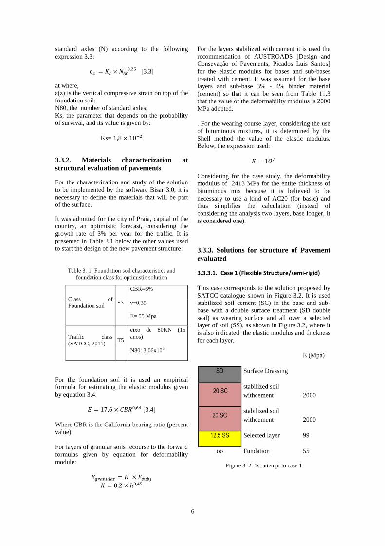
3.3.3. Solutions for structure of Pavement
evaluated
3.3.3.1. Case 1 (Flexible Structure/semi-rigid)
This case corresponds to the solution proposed by
SATCC catalogue shown in Figure 3.2. It is used
stabilized soil cement (SC) in the base and sub-
base with a double surface treatment (SD double
seal) as wearing surface and all over a selected
layer of soil (SS), as shown in Figure 3.2, where it
is also indicated the elastic modulus and thickness
for each layer.
E (Mpa)
SD Surface Drassing
20 SC stabilized soil
withcement 2000
20 SC stabilized soil
withcement 2000
12,5 SS Selected layer 99
ᴏᴏ Fundation
55
Figure 3. 2: 1st attempt to case 1
Class of
Foundation soil S3
CBR=6%
ν=0,35
E= 55 Mpa
Traffic class
(SATCC, 2011) T5
eixo de 80KN (15
anos)
N80: 3,06x10⁶

7
3.3.3.2. Case 2 (Flexible Structure/semi-rigid reverse)
This case corresponds to the solution proposed by
SATCC catalogue shown in Figure 3.3. It is used
crusher runin the base layer and stabilized soil
cement (SC) in the sub-base with a double surface
treatment (SD) as wearing surface and all over a
selected layer of soil (SS), as shown in Figure 3.3.
3.3.3.3. 3 (Flexible Structure)
The third and last structural solution is considered
the most common and usual with regard to flexible
pavements. The proposal made by SATCC
catalogue consists of a pavement with an asphalt
concrete wearing course and two granular layers
(crusher run) as subbase and base layers, as can be
seen in Figure 3.4. In order to obtain an optimized
solution, like on the previous solutions, several
attempts have been tested / iterations through the
Encore program, changing some variants to the
method of Shell.
For the three cases several iteration were
performed on the software, changing thicknesses
of the layers, mechanical characteristics of the
materials or removing some layers in order to find
an optimal solution for each case.
3.3.4. Conclusion on structural solutions
The solution 1 for the first attempt with 95%
confidence, the pavement structure was over-
designed as the values for damage due to fatigue
reached only 4% and 3% damage due to
permanent deformation.
For the 2nd, 3rd and 4th iterations it was observed
that that the proposed solutions exceed the
acceptable limits. Thus, it was possible to
conclude that the proposed structures do not
support the considered loads for the time
spanconsidered, not being therefore viable
structures.
On the fifth and last iteration the elastic modulus
of layers of soil cement was increased to 2500
MPa, as it is assumed a material of less quality,
thereby increasing the proportion of cement in the
soil (up to 4.5%) and consequently increasing the
elastic modulus.
Note that the increase in cement soil characteristics
of the 2nd attempt led to a solution that, a priori, it
would be good practice due to poor fatigue
behavior of the cross layer to be an acceptable
solution, with a rate of 100% fatigue damage to the
useful life of the road. Although this solution is not
an optimum solution, since this range of values is
not between 60 to 80% damage, or reaches the end
of life of the floor with a damage 60 to 80% of the
structure, this constitutes a good approximation of
what is intended to analyze, considering so this as
the best solution found. Proceeds to the analysis of
the case 2, consisting of soil-cement layer,
granular layer ABGE, selected soil and surface
coating.
For the case 2 it was possible to observe that for
the first attempt, and for a reliability of 95%, these
values are much greater than the desired
percentage, which leads us to conclude that
solution is infeasible, giving damages about
2000%, or is the structure does not support the
loads to which it is subject.
The second attempt is the solution best adapted to
the characteristics required by this solution. With
damage to the fatigue of 67% and damage to
permanent deformation of 23%, this presents, not a
great solution, but considered rather interesting
technological point of view.
The third attempt is to add another layer SC at the
second attempt. This has lower damage as would
be espectável.
Given the presence of soil stabilized with cement,
similar to the first structural solution, the fourth
attempt is to alter the proportion of cement in
relation to its incorporation third attempt, causing
the deformability modulus increases to 2500MPa.
SD Surface dressing
15 ABGE ABGE
500
25 SC stabilized soil
withcement 2000
15 SS Selected layer 105
ᴏᴏ Fundation
55
Figure 3. 3: 1st attempt to case 2
Figure 3. 4
5 BB Hot mix asphalt 2413
20 ABGE ABGE
311
30 ABGE ABGE
143
ᴏᴏ Foundation
55
Figure 3. 4: 1st attempt to case 3

8
Although the damage associated with this new
attempt have decreased considerably to about
300% to fatigue, this solution is not feasible.
The third and final case, it is possible to observe
that the sixth attempt is the only solution that
respects the ruin of criteria to fatigue and
permanent deformation, with 74% and 37%
respectively, while the remaining go beyond the
acceptable values. Recall that this structure is the
most common in Cape Verde, not necessarily the
cheapest nor the most efficient. Although ruin
criteria are closer to the range of values that you
want, consider a bituminous concrete layer 13cm
thick is not the most common in Cape Verde. In
general, wear layers 5 to 8 cm are most frequently
used, but it is also observed that, although not
verify the destruction of the flooring, pavements
reaching the end of its useful life without the need
for intervention because its inability to withstand
the loads they are subjected to the effect of rain
and not least the high temperatures to which they
are subject.
3.4. Cost analysis of paving proposals
A cost analysis was performed for all the proposed
solutions. The analysis was based on established
costs for the Portuguese realityw which is a fairly
good approximation to the Cape Verdean reality,
although for Cape Verde it should be considered
additional costs for the import of the materials,
especially the bitumen.
The following prices, shown in Table 3.3, were
considered for the analysis :
Table 3.3: materials price list for paving employed in
Portugal
Materials Measuring
unit Cost
Selected soil €/m²/15cm 1,80€/m²/15cm
Granular layer
(ABGE) €/m²/20cm
4,00€/m²/20cm
Granular (ABGE)
layes stabilized
with cement
€/m²/20cm
4,80€/m²/20cm
Surface dressing €/m² 2,5€/m²
BB (hot mix
asphalt) €/m²/cm
1€/m²/cm de
espessura
For the 1st solution proposed, composed by 15m
layer of selected soil, a 30cm layer of soil cement,
divided in two layers of 15cm and by a wearing
course with double surface tretment, the associated
costs are 14,0 €/m², equivalent to 1540 ECV (Cape
Verdean currency)
For Case 2, this is constituted, by double surface
coating, granular layers, soil-cement layers and
selected soil. the second proposed solution has a
total cost per square meter of 14.8 €, equivalent to
1628ECV.. As can be seen, there was an increase
in the cost of the solution from the previous
solution.
In case 3, it can be observed that the cost
associated with this structural solution is 19 € / m²,
corresponding to 2090 ECV.
By comparing with previous proposals it can be
verified a considerable increase on the costs
associated with this solution, which was expected,
considering the thickness of the asphalt concrete
layer of this solution. It is possible to concludethat
the granular layers are less expensive when
compared to asphalt concrete layer.
4. Conclusions
Figures 3.5, 3.6 and 3.7 below indicates the
percentage of material used in terms of costs
associated to the proposed solution. It can be seen ,
for the case 1, that 33% of the total value of this
proposal is due to the surface dressing and 47%
due to layers bonded with cement.
For the case 2 and observing the figure 3.6 it can
conclude that in terms of costs, layers stabilized
with cement and the surface dressing layer have
the highest percentage of the total cost of the
solution.
Finally, it is also possible to observe by the figure
3.7 that for the case 3, 68% of the cost of this
solution is due to the hot mix asphalt layer.
The results and comparative analysis of pavement
structures considered, showed that the stabilized
soil solutions have the potential to replace the

9
more traditional pavement, "BB" type, providing
better results when we compare of cost, simplicity
of execution and ability to withstand the loads
imposed .
Figure 3. 5: Percentage cost associated for case 1
Figure 3. 6: Percentage cost associated for case 2
Figure 3. 7: Percentage cost associated for case 3
The results and comparative analysis of pavement
structures considered, showed that the stabilized
soil solutions have the potential to replace the
traditional pavement, "BB" type. It was observed
that, besides having solid structural behavior, the
soil solutions stabilized with cement to wear layer
surface implies lower costs, under specified
conditions, to fix the bracket identified as critical
traffic.
At figure 3.8 it is possible to observe de total costs
of each case studying .
Figure 3. 8: Total costs per square meter of each case
Therefor, it is necessary to reinforce the fact that
the technology for the production of stabilized soil
depend largely on the type of soil available. So, is
required a more consistent validation in particular
on the behavior of these with actually available
materials and also with regard to the development
of pathologies that may not be compatible with the
service required by certain routes.
33%
23% 24%
20%
Percentage cost associated with each paving layer- Solution 1
revestimento superficial duplo
Camada Granular (ABGE) aglutinada comcimento
Camada Granular (ABGE) aglutinada comcimento
Camada de solo seleccionado
34%
20%
34%
12%
Percentage cost associated with each paving layer- Solution 1
revestimento superficial duplo
Camada Granular (ABGE)
Camada Granular (ABGE) aglutinadacom cimento
Camada de solo seleccionado
68%
32%
Percentage cost associated with each paving layer- Solution 3
betão betuminoso
Camada Granular (ABGE)
Caso 1 Caso 2 Caso 3
1540 1628 2090
Paving costs of each structural solution (Cape Verdeans Shields)
Custos de pavimentação (EscudosCaboverdianos)

10
References
CEBPT, LCPC 1955. “ Manuel pour le
renforcement des chaussées souples en pays
tropicaux
CEBPT, 1994. “ Guide pratique de
dimensionnement des chaussés pour les pays
tropicaux
Antunes, M. L.; Baptista, F.; Fontul, S.;
Domingos, P., 2006. “Conservação e reabilitação
de pavimentos rodoviários”. Laboratório Nacional
de Engenharia Civil, Lisboa.
Branco, F.; Pereira, P.; Picado-Santos, L., 2011.
“Pavimentos Rodoviários”. Edições Almedina, 4ª
Reimpressão
Jorge, L. C. D. L., 2014. “Constituição,
dimensionamento e conservação de pavimentos
para baixos volumes de tráfego”. Dissertação de
Mestrado, Instituto Superior de Engenharia de
Coimbra
Santos, S. B. D., 2015. “Dimensionamento de
pavimentos em África e América Latina”.
Dissertação de Mestrado, Faculdade de
Engenheira, Universidade do Porto
Cepsa Betumes, 2007. “Manual de
Pavimentação”. 2ª Edição Disponível em
www.cepsa.com. [Ficheiro obtido a 30 de Outubro
de 2015]
EP, 2012. “Caderno de Encargos Tipo Obra- 14.03
– Pavimentação: Características dos materiais”.
Estradas de Portugal, S.A.
Neves, J. M. C., 2009. “Módulo B -
Pavimentação”. Construção e Manutenção de
Infraestruturas de Transportes, Folhas da
disciplina, Instituto Superior Técnico,
Universidade Técnica de Lisboa.
Picado-Santos, L.; Branco, F.; Capitão, S., 2000.
“Vias de Comunicação, Volume 1 e 2”.
Departamento de Engenharia Civil, Faculdade de
Ciências e Tecnologia, Universidade de Coimbra.
Shell International Petroleum Company,
l., Shell pavement design manual : asphalt
pavements
and overlays for road traffic. 1978: London : Shell
International Petroleum.
Antunes, M., Modelação do comportamento de
pavimentos rodoviários flexíveis. LNEC,
Programa de Investigação e Programa de Pós-
Graduação, Lisboa, 2005.
Diretivas para a concepção de pavimentos,
Critérios de dimensionamento, INIR (Instituto de
nfra-Estruturas Rodoviárias)
Martins, D. F. C., 2007. “Estudo e Avaliação das
Patologias dos Pavimentos Rodoviários”.
Dissertação de Mestrado, Departamento de
Engenharia Civil do Instituto Superior Técnico,
Lisboa.
Neves, J. M. C., 2010. “Aula T7 – Pavimentos”.
Construção e Manutenção de Infraestruturas de
Transportes, Slides da disciplina, Instituto Superior
Técnico, Universidade de Lisboa.