Embed Size (px)
Citation preview
EPJ Appl. Metamat. 6, 4 (2019)© J. Han et al., published by EDP Sciences, 2019https://doi.org/10.1051/epjam/2019003
Available online at:epjam.edp-open.org
RESEARCH ARTICLE
Control and improvement of antenna gain by using multilayernon-uniform metasurfacesJiaqi Han, Long Li*, Tianliang Zhang, and Rui Xi
Xidian University, Xi’an, Shaanxi, PR China
* Correspo
This is an O
Received: 24 December 2017 / Accepted: 2 January 2019
Abstract. In this paper, a new high-gain antenna with beam control based on multilayer non-uniformmetasurfaces (MNMSs) is proposed. The MNMS consists of multilayer non-uniform square and ring metalpatches array. The phase-shift of the MNMS element can achieve 310° with the variation of geometrical sizes.Moreover, four high-gain antennas based onMNMS element are designed, fabricated, andmeasured to realize 0°,30°, 45°, and 60° beam control in pitching plane, respectively. Relative bandwidth of the proposed high-gainantenna is above 12%. The simulated and measured results of the proposed antennas show that the wide-angleand azimuth direction beam control capability can be effectively realized by integrating different MNMS withthe feeding horn antenna.
Keywords: Beam control / high-gain antenna / multilayer metasurfaces / metasurface
1 Introduction
Metasurface (MS) is a two-dimensional metamaterialstructure, which is typically engineered by arranging aset of electrically small scatterers into a two-dimensionalpattern at a surface or interface. In recent years, on thebasis of the traditional multilayer frequency selectivesurface (FSS), a design method of achieving wideband MSby utilizing multilayer non-resonant structure is proposed[1–3]. As can be referred in [3], the miniaturizationpossesses the advantages of good frequency selection,angle stability, and a larger range of phase-shift. A gooddesign of Huygens’ MS for refraction of normally incidentbeam towards 71.8 degrees was presented in [4]. Accordingto the theory of array antenna, the phase shifts of each unitof the MS need to be compensated to adjust and control theelectromagnetic waves propagation direction. The theoryof phase compensation [5–7] of the transmission arrayantenna is based on the compensation of the pathtransmission from the center of the feeding antenna[8–10]. Most previous studies mainly focused on steeringelectromagnetic waves using uniform MSs [11–16]. In thispaper, we propose a non-uniform MS to control andimprove the gain of a feeding antenna. A standard X-bandhorn antenna is used as a feeding source. According to thetheory of array antenna, the main beam direction controland high gain antenna can be achieved by integratingmultilayer non-uniform metasurfaces (MNMSs). In this
nding author: [email protected]
pen Access article distributed under the terms of the Creative Comwhich permits unrestricted use, distribution, and reproduction
paper, by varying the size of the square patch and the gridline to adjust the transmission phase of MNMS, theproposed high-gain antenna can realize a flexible beamcontrol. The X-band high-gain antennas are implementedby using different MNMS, and the main beam with anglesof u=0°, u=30°, u=45°, and u=60° are realized,respectively. Also the beam control ability in azimuthplane is studied when the main beam is in a particulardirection of u=30°. Simulation and experiment resultsprove that the feeding horn antenna integrating withMNMS is a good method to achieve high gain and wide-angle beam control.
2 Antenna element
In this paper, the MNMS unit is composed of non-uniformstructures, which can be analyzed by using an effectivecircuit model and J/K inverter. The technique is often usedto analyze and synthesize a microwave filter and amultilayer FSS [17,18]. When the unit cell layer (order)increases, the bandwidth and the transmission phase-shiftrange will increase.
The MNMS unit is used to form a high-gain antennathat meets the purpose of beam control [19,20]. The phasecompensation includes the phase delay caused by thedifferent paths of electromagnetic wave from feed horn toeach unit and phase difference of each unit for beamcontrol. The way of phase compensation is by regulatingMNMS unit size to adjust the transmission phase shift. Forthe proposed third-order unit, two parameters are chosen
mons Attribution License (http://creativecommons.org/licenses/by/4.0),in any medium, provided the original work is properly cited.
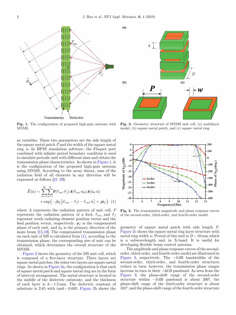
Fig. 1. The configuration of proposed high-gain antenna withMNMS.
Fig. 2. Geometry structure of MNMS unit cell, (a) multilayermodel, (b) square metal patch, and (c) square metal ring.
Fig. 3. The transmission magnitude and phase response curvesof the second-order, third-order, and fourth-order model.
2 J. Han et al.: EPJ Appl. Metamat. 6, 4 (2019)
as variables. These two parameters are the side length ofthe square metal patch P and the width of the square metalring w. In HFSS simulation software, the Floquet portcombined with infinite period boundary condition is usedto simulate periodic unit with different sizes and obtain thetransmission phase characteristics. As shown in Figure 1, itis the configuration of the proposed high-gain antennausing MNMS. According to the array theory, sum of theradiation field of all elements in any direction will beexpressed as follows [21–29]:
~EðuÞ ¼XM
m¼1
XN
n¼1
Fð~rmn⋅~rfÞAð~rmn⋅u0ÞAðu0⋅uÞ
� exp �jk0 j~rmn �~rf j �~rmn⋅u� �þ jfC
� � ð1Þ
where A represents the radiation pattern of unit cell, Frepresents the radiation pattern of a feed, ~rmn and ~rfrepresent mnth radiating element position vector and thefeed position vector, respectively. fC is the compensatedphase of each unit, and u0 is the primary direction of themain beam [15,19]. The compensated transmission phaseon each unit of MS is calculated from (1), according to thetransmission phase, the corresponding size of unit can beobtained, which determines the overall structure of theMNMS.
Figure 2 shows the geometry of the MS unit cell, whichis composed of a five-layer structure. Three layers aresquare metal patches, the other two layers are square metalrings. As shown in Figure 2a, the configuration is that eachof square metal patch and square metal ring are in the formof interval arrangement. The metal structure is located inthe middle of the dielectric substrate, and the thicknessof each layer is h=1.5mm. The dielectric constant ofsubstrate is 2.65 with tand=0.005. Figure 2b shows the
geometry of square metal patch with side length P.Figure 2c shows the square metal ring layer structure withmetal ring width w. Period of this unit is D=10mm whichis a subwavelength unit in X-band. It is useful fordeveloping flexible beam control antenna.
The amplitude and phase response curves of the second-order, third-order, and fourth-ordermodel are illustrated inFigure 3, respectively. The �3 dB bandwidths of thesecond-order, third-order, and fourth-order structuresreduce in turn; however, the transmission phase rangesincrease in turn in their �3dB passband. As seen from theFigure 3, the phase-shift range of the second-orderstructure within �3 dB passband is about 200°, thephase-shift range of the third-order structure is about310°, and the phase-shift range of the fourth order structure

Fig. 4. The effect of size of MNMS unit on the transmissionphase and magnitude of S21, (a) P and (b) w.
Fig. 5. The reflection coefficient of the MNMS unit, (a) themagnitude of S11, (b) the phase of S11.
Fig. 6. Overall model of the high-gain antenna with MNMS.
J. Han et al.: EPJ Appl. Metamat. 6, 4 (2019) 3
is about 400°. The transmission phase characteristics areadjusted by changing the unit size. However, as the layernumbers of the MS increase, the phase sensitivity and thelinearity will decrease, which is very important in thedesign of high-gain antenna and it affects the accuracy ofthe design. Therefore, the third-order element is selected toform the MNMS with a phase range of 310° in this paper,which basically meets the design requirements of the beamcontrol.
As shown in Figure 4, the side length of square metalpatch P and the width of square metal ring w have anobvious impact on the phase and magnitude of transmis-sion coefficient S21 of the MNMS unit. The center workingfrequency is f=10GHz. It is shown that the side length ofmetal patch P and the width of square metal ring wimpact on MNMS unit transmission phase and transmis-sion coefficient. When selecting the range of the unit sizeparameter, one can make the changing of metal patchessize P more closely and the width of metal ring moresparsely. Finally, the transmission phase shift range for arelatively suitable transmission coefficient of 310° isdetermined. Figure 5 is the reflection coefficient of theMNMS unit. The S11 magnitude in the operating band isless than �10 dB, which indicates good working perfor-mance. The phase characteristic of the reflection coeffi-cient is shown in Figure 5b, the reflection phase shift rangeof the unit in the operating band reaches 315°. It alsocorresponds to the phase shift range of the transmissioncoefficient of the third-order unit.
3 High-gain antenna design and analysis
As shown in Figure 6, the high-gain antenna is designedwith 20� 20 MNMS units, and a standard horn antennaworking at X-band is utilized as the feed. The length ofthe horn antenna is 100mm, and the aperture size is50mm� 40mm. The relative location of the MS and thefeeding antenna is set as F/D=0.5, where the distancebetween the MNMS and horn antenna is set as F, and
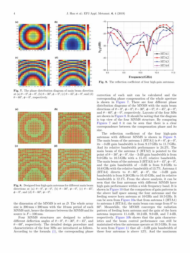
Fig. 7. The phase distribution diagram of main beam directionat (a) u=0°, f=0°, (b) u=30°, f = 0°, (c) u=45°, f=0°, and (d)u=60°, f=0°, respectively.
Fig. 8. Designed four high-gain antennas for differentmain beamdirections at (a) u=0°, f=0°, (b) u=30°, f=0°, (c) u=45°,f=0°, and (d) u=60°, f=0°.
Fig. 9. The reflection coefficient of four high-gain antennas.
4 J. Han et al.: EPJ Appl. Metamat. 6, 4 (2019)
the dimension of the MNMS is set as D. The whole arraysize is 200mm� 200mm with the 10mm period of eachMNMS unit, hence the distance between theMNMS and itssource is F=100mm.
Four MNMS structures are designed to achievedifferent deflection angles of u=0°, u=30°, u=45°, andu=60°, respectively. The detailed design procedure andcharacteristics of the four MSs are introduced as follows.According to the formula (1), the corresponding phase
correction of each unit can be calculated and thecorresponding phase compensation of the whole apertureis shown in Figure 7. There are four different phasedistribution diagrams of the MNMS with the main beamdirections of u=0°, f=0°; u=30°, f=0°; u=45°, f=0°;and u=60°, f=0°, respectively. Layouts of the four MSsare shown in Figure 8. It should be noting that the diagramis top view of the four MNMS structure. By comparingFigures 7 and 8 it can be seen that there is a clearcorrespondence between the compensation phase and itssize.
The reflection coefficient of the four high-gainantennas with different MNMS is shown in Figure 9.The main beam of the antenna 1 (HTA1) is u=0°, f=0°,its �3 dB gain bandwidth is from 9.17GHz to 11.7GHz.And its relative bandwidth performance is 24.2%. Themain beam of the antenna 2 (HTA2) is pointed to thepoint of u=30°, f=0°, the �3 dB gain bandwidth is from9.0GHz to 10.5GHz with a 15.4% relative bandwidth.The main beam of the antenna 3 (HTA3) is u=45°, f=0°,and the gain bandwidth of �3 dB is from 9.3GHz to10.6GHz with the relative bandwidth of 13.7%. Antenna 4(HTA4) directs to u=60°, f=0°, the �3 dB gainbandwidth is from 9.26GHz to 10.45GHz, and its relativebandwidth is 12.1%. From the above analysis, it can beseen that the four antennas with different MNMS havehigh gain performance within a wide frequency band. It isshown in Figure 10 that the comparison of gain patterns inthe above half space among the four antennas and thefeeding source horn antenna at 10GHz and 10.5GHz. Itcan be seen from Figure 10a that from antenna 1 (HTA1)to antenna 4 (HTA4), the main beam can range from 0° to60°. Meanwhile, the MNMS converges the radiationpattern of feeding horn antenna and the gain of the hornantenna improves 11.4 dB, 10.2 dB, 9.0 dB, and 7.4 dB,respectively. Figure 10b shows that the gain character-istics and the beam control performance can still bemaintained when the antennas operate at 10.5GHz. It canbe seen from Figure 11 that all �3 dB gain bandwidth ofthese four antennas is above 12%. And the maximum
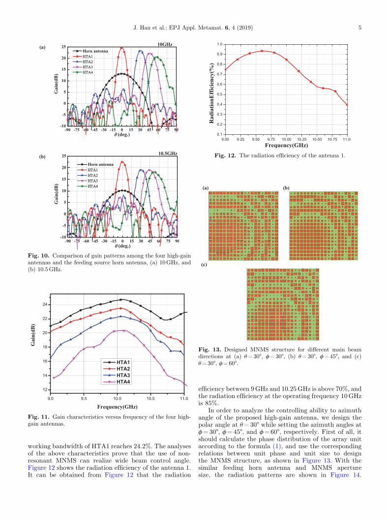
Fig. 10. Comparison of gain patterns among the four high-gainantennas and the feeding source horn antenna, (a) 10GHz, and(b) 10.5GHz.
Fig. 11. Gain characteristics versus frequency of the four high-gain antennas.
Fig. 12. The radiation efficiency of the antenna 1.
Fig. 13. Designed MNMS structure for different main beamdirections at (a) u=30°, f=30°, (b) u=30°, f=45°, and (c)u=30°, f=60°.
J. Han et al.: EPJ Appl. Metamat. 6, 4 (2019) 5
working bandwidth of HTA1 reaches 24.2%. The analysesof the above characteristics prove that the use of non-resonant MNMS can realize wide beam control angle.Figure 12 shows the radiation efficiency of the antenna 1.It can be obtained from Figure 12 that the radiation
efficiency between 9GHz and 10.25GHz is above 70%, andthe radiation efficiency at the operating frequency 10GHzis 85%.
In order to analyze the controlling ability to azimuthangle of the proposed high-gain antenna, we design thepolar angle at u=30° while setting the azimuth angles atf=30°, f=45°, and f=60°, respectively. First of all, itshould calculate the phase distribution of the array unitaccording to the formula (1), and use the correspondingrelations between unit phase and unit size to designthe MNMS structure, as shown in Figure 13. With thesimilar feeding horn antenna and MNMS aperturesize, the radiation patterns are shown in Figure 14.
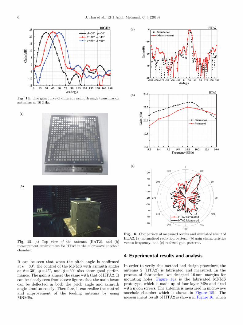
Fig. 14. The gain curve of different azimuth angle transmissionantennas at 10GHz.
Fig. 15. (a) Top view of the antenna (HAT2), and (b)measurement environment for HTA2 in the microwave anechoicchamber.
Fig. 16. Comparison of measured results and simulated result ofHTA2, (a) normalized radiation pattern, (b) gain characteristicsversus frequency, and (c) realized gain patterns.
6 J. Han et al.: EPJ Appl. Metamat. 6, 4 (2019)
It can be seen that when the pitch angle is confirmedat u=30°, the control of the MNMS with azimuth anglesat f=30°, f=45°, and f=60° also show good perfor-mance. The gain is almost the same with that of HTA2. Itcan be clearly seen from above figures that the main beamcan be deflected in both the pitch angle and azimuthangle simultaneously. Therefore, it can realize the controland improvement of the feeding antenna by usingMNMSs.
4 Experimental results and analysis
In order to verify this method and design procedure, theantenna 2 (HTA2) is fabricated and measured. In theprocess of fabrication, we designed 10mm margins formounting holes. Figure 15a is the fabricated MNMSprototype, which is made up of four layer MSs and fixedwith nylon screws. The antenna is measured in microwaveanechoic chamber which is shown in Figure 15b. Themeasurement result of HTA2 is shown in Figure 16, which
J. Han et al.: EPJ Appl. Metamat. 6, 4 (2019) 7
shows the gain characteristics at eight frequency pointsfrom 9.2GHz to 10.6GHz. The comparison of normalizedsimulation and measurement radiation patterns at 10GHzis shown in Figure 16. It can be seen that the measuredHTA2 results get a little worse compared to simulationones. The main reason is due to the fabrication errors of themetal size and the air gap of the different layers; however,the measured and simulated beam control angles arebasically consistent.
5 Conclusion
In this paper, a new high-gain antenna based onMNMSs isproposed. By utilizing the MNMS unit, different compen-sation phases are designed to direct the main beam to0°, 30°, 45°, and 60° in the pitch angles with high-gain.Moreover, it is analyzed that the beam ability of thefeeding antenna composed of MNMS units in the azimuth,which can realize the main beam at three azimuth anglesof 30°, 45°, and 60° which also achieve high gaincharacteristics. By testing the example of HTA2, theexperimental results and the simulation results are in goodagreement, which verifies the properties of high gain andbeam deflection. The simulation and the measurementresults of the proposed antenna show that it can realizethe flexible improvement and control of feed beamradiation by employing MNMS.
This work is supported by National Key R&D Program of China,and is supported by National Natural Science Foundation ofChina under Contract No.51477126, and supported by Technol-ogy Explorer and Innovation Research Project.
References
1. B.A. Munk, Frequency selective surfaces: theory and design(Wiley, New York, 2000)
2. A.H. Abdelrahman, A.Z. Elsherbeni, F. Yang et al.,Transmission phase limit of multilayer frequency-selectivesurface for transmitarray designs, IEEE Trans. AntennasPropag. 62, 690 (2014)
3. Y. Zhang, R. Mittra, W. Hong, A zoned two-layer flat lensdesign, International Workshop on Antenna Technology(iWAT2011), March 2011, pp. 412–415
4. M. Chen, E. Abdo-Sanchez, A. Epstein, G.V. Eleftheriades,Theory, design, and experimental verification of a reflection-less bianisotropic Huygens’ metasurface for wide-anglerefraction, Phys. Rev. B 97, 125433 (2018)
5. M.A. Al-Joumayly, N. Behdad, Wideband planar microwavelenses using sub-wavelength spatial phase shifters, IEEETrans. Antennas Propag. 59, 4542 (2011)
6. C.G.M. Ryan, M.R. Chaharmir, J. Shaker et al., A widebandtransmitarray using dual-resonant double square rings, IEEETrans. Antennas Propag. 58, 1486 (2010)
7. M. Sazegar, Y. Zhegn, C. Kohler et al., Beam steeringtransmitarray using tunable frequency selective surface withintegrated ferroelectric varactors, IEEE Trans. AntennasPropag. 60, 5690 (2012)
8. L. Wang, X. Yin, S. Li et al., Phase corrected substrateintegrated waveguide H-plane horn antenna with embeddedmetal-via arrays, IEEE Trans. Antennas Propag. 62, 1854(2014)
9. D. Ramaccia, F. Scattone, F. Bilotti et al., Broadbandcompact horn antennas by using EPS-ENZ metamateriallens, IEEE Trans. Antennas Propag. 61, 2929 (2013)
10. D. Ramaccia, M. Barbuto, A. Monti et al., Exploitingintrinsic dispersion of metamaterials for designing broadbandaperture antennas: theory and experimental verification,IEEE Trans. Antennas Propag. 64, 1141 (2016)
11. H. Nokano, S. Mitsui, J. Yamauchi, Tilted-beam high gainantenna system composed of a patch antenna and periodi-cally arrayed loops, IEEE Trans. Antennas Propag. 62, 2917(2014)
12. A.K. Layer, G.V. Eleftheriades, A multilayer negative-refractive-index transmission-line (NRI-TL) metamaterialfree-space lens at X-band, IEEE Trans. Antennas Propag.55, 2746 (2007)
13. L. Meng, M. Behdad, Wideband true-time-delay microwavelenses based on metallo-dielectric and all-dielectric lowpassfrequency selective surfaces, IEEE Trans. Antennas Propag.61, 4109 (2013)
14. Y.J. Lee, J. Yeo, R. Mittra et al., Thin frequency selectivesurfaces (FSS) superstrate with different periodicities fordual-band directivity enhancement, IEEE InternationalWorkshop on Antenna Technology: Small Antennas andNovel Metamaterial, March 2005
15. G.V. Trentini, Partially reflecting sheet arrays, IRE Trans.Antennas Propag. 4, 666 (1956)
16. D.M. Pozar, S.D. Targonski, H.D. Syrigos, Design ofmillimeter wave micropatch reflectarrays, IEEE Trans.Antennas Propag. 45, 287 (1997)
17. Y. Li, L. Li, Y. Zhang, C. Zhao, Design and synthesis ofmultilayer frequency selective surface based on antenna-filter-antenna using Minkowski fractal structures, IEEETrans. Antennas Propag. 63, 133 (2015)
18. T. Zhang, L. Li,R.Xi, Design of amultilayer FSS transmissionhigh-gain antenna array and analysis of the beam control,Asia-Pacific Conference on Antennas and PropagationAPCAP’2017, October 2017, Xi’an, China, pp. 285–287
19. J. Huang, J.A. Encinar, Reflectarray antennas (Wiley-IEEEPress, United States of America, 2008)
20. Y. Hao, A.H. Alomainy, C.G. Parini, Antenna-beam shapingfrom offset defects in UC-EBG cavities, Microw. Opt.Technol. Lett. 43, 108 (2004)
21. H. Moghadas, M. Daneshmand, P. Mousavi, Half-phase-gradient partially reflective surface for a reconfigurable dual-beam scanning cavity antenna, Antennas and Propagationon Society International Symposium, July 2012, pp. 1–2
22. H. Kaouach, L. Dussopt, J. Lanteri et al., Wideband low-losslinear and circular polarization transmitarrays in V-band,IEEE Trans. Antennas Propag. 59, 2513 (2011)
23. C. Pfeiffer, A. Grbic, Millimeter-wave transmitarrays forwavefront and polarization control, IEEE Trans. AntennasPropag. 61, 4407 (2013)
24. H.Hasani,M.Kamyab,A.Mirkamali, Broadband reflectarrayantenna incorporating disk elements with attached phase-delay lines, IEEEAntennasWirel. Propag. Lett. 9, 156 (2010)
25. E. Almajali, D. Mcnamara, J. Shaker et al., Derivation andvalidation of the basic design equations for symmetric sub-reflectarrays, IEEETrans. Antennas Propag. 60, 2336 (2012)

8 J. Han et al.: EPJ Appl. Metamat. 6, 4 (2019)
26. D.C. Chang, M.C. Huang, Multiple-polarization micropatchreflectarray antenna with high efficiency and low cross-polarization, IEEE Trans. Antennas Propag. 43, 829 (1995)
27. Y. Li, M.E. Bialkowski, A.M. Abbosh, Single layerreflectarray with circular rings and open-circuited stubs forwideband operation, IEEE Trans. Antennas Propag. 60,4183 (2012)
28. C. Han, C. Rodenbeck, K. Chang et al., A C/Ka dualfrequency dual layer circularly polarized reflectarray antennawith micropatch ring elements, IEEE Trans. AntennasPropag. 52, 2871 (2004)
29. W. Hu, M. Arrebola, R. Cahill, 94 GHz dual-reflectorantenna with reflectarray subreflector, IEEE Trans.Antennas Propag. 57, 3043 (2009)
Cite this article as: Jiaqi Han, Long Li, Tianliang Zhang, Rui Xi, Control and improvement of antenna gain by using multilayernon-uniform metasurfaces, EPJ Appl. Metamat. 6, 4 (2019)


![Gain Enhancement of Rectangular Microstrip Patch Antenna ... SPECIAL...Illustration of a patch antenna [4]. In most applications, it is required to design an antenna with high gain](https://img.pdfslide.net/doc/110x75/6041bcb849cb3d371875f64a/gain-enhancement-of-rectangular-microstrip-patch-antenna-special-illustration.jpg)