Embed Size (px)
Citation preview

International Journal of InnovativeComputing, Information and Control ICIC International c©2012 ISSN 1349-4198Volume 8, Number 10(B), October 2012 pp. 7237–7248
CONTROL AND SYNCHRONIZATION OF CHAOSIN AN INDUCTION MOTOR SYSTEM
Diyi Chen1, Peng Shi2,3 and Xiaoyi Ma1
1Department of Electrical EngineeringNorthwest A&F University
No. 3, Taicheng Road, Yangling 712100, P. R. [email protected]; [email protected]
2Department of Computing and Mathematical SciencesUniversity of Glamorgan
Pontypridd, CF37 1DL, United [email protected]
3School of Engineering and ScienceVictoria University
PO BOX 14428, Melbourne, VIC 8001, Australia
Received August 2011; revised December 2011
Abstract. This paper brings attention to the nonlinear dynamics of an induction mo-tor’s drive system with indirect field controlled. To understand the complex dynamics ofsystem, some basic dynamical properties, such as equilibrium, stability are rigorously de-rived and studied. Chaotic attractors are first numerically verified through investigatingphase trajectories, bifurcation path, Poincare projections and dissipativity. Furthermore,a new sliding mode control method is proposed to gain the synchronization with differentinitial values. It can control the system to an equilibrium point. Numerical simulationsare presented to demonstrate the effectiveness of the proposed controllers.Keywords: Induction motor, Chaos, Chaos control, Synchronization
1. Introduction. Chaotic behavior has been extensively analyzed in many fields such asmathematics [1], physics [2], biology [3], mechanical [4] and electrical engineering [5]. Asa matter of fact, chaos may occur in natural processes. Controlling these complex chaoticdynamics for engineering applications has emerged as a new and attractive field and hasdeveloped many profound theories and methodologies.
Motor is a device, which is widely applied in industry for energy conversion betweenenergy and mechanical energy. Many achievements have been proposed. For example,Ataei et al. [6] characterized the complex dynamics of the permanent-magnet synchronousmotor (PMSM) model with a non-smooth-air-gap. A bifurcation analysis was applied to aPermanent Magnet (PM) stepper motor, and the nonlinear control was designed by Jing,Yu and Chen [7]. Harb and Zaher [8] studied chaotic behaviors in Permanent MagnetSynchronous Motor (PMSM) for a certain range of its parameters, and it was eliminatedby using optimal Lyapunov exponent methodology. Zribi and his co-workers [9] proposedto use an instantaneous Lyapunov exponent control algorithm to control the PermanentMagnet Synchronous Motor (PMSM). Dynamical equations of three time scale brushlessDC motor system were presented by Ge and Cheng [10]. Chaotic anti-control and chaoticsynchronization of the system were also studied. Fossi and Woafo [11] presented thedynamical model of an induction motor activating a mobile plate fixed to a spring and theelectromechanical equations were formulated, and anti-control of chaos in the induction
7237
7238 D. CHEN, P. SHI AND X. MA
motor was also obtained using the field-oriented control associated to the time delayfeedback control. Anti-control of chaos in single time scale brushless DC motors (BLDCM)and chaotic synchronization of different order systems were also studied by Ge, Changand Chen [12]. To control the undesirable chaos in the permanent magnet synchronousmotor (PMSM), an adaptive dynamic surface control law was designed by Wei and hiscopartners [13]. The purpose of paper [14] was to employ time-delay feedback to anti-control a permanent magnet DC (PMDC) motor system for vibratory compactors. Yu etal. [15] developed an adaptive fuzzy control method to suppress chaos in the permanentmagnet synchronous motor drive system via back stepping technology. However, there arefew contributions to a current-driven induction motor, especially, the dynamical modelfor a whole induction motor system with indirect field controlled. While, it is a maindrive device in modern industry, and its nonlinear vibration is catholic. Therefore, it isnecessary to study the intrinsic quality of its nonlinear vibration via nonlinear dynamicstheory.Chaos control is inquisitive in how to control the chaotic system to the periodic orbit
or equilibrium point with the original parameters remained or only fine-tuned, becausethe system parameters can not be changed objectively, or the parameters change largelymust pay a great price. Typical control methods have been proposed to achieve chaoscontrol. For instance, two methods of chaos control with a small time continuous pertur-bation were proposed by Pyragas [16]. Ataei et al. [17] presented a chaos synchronizationmethod for a class of uncertain chaotic systems using the combination of an optimalcontrol theory and an adaptive strategy. Wang and his coworkers [18] used symbolic dy-namics and the automaton reset sequence to identify the current drive word and obtainedthe synchronization. Nonlinear and linear feedback controllers were designed to controland synchronize the chaotic system by Rafikov et al. [19]. Golovin et al. [20] proposeda global feedback control method based on measuring the maximum of the pattern am-plitude over the domain, which can stabilize the system. Based on OGY approach, amultiparameter semi-continuous method was designed to control chaotic behavior by dePaula and Savi [21]. The united chaotic systems with uncertain parameters were synchro-nized based on the CLF method by Wang et al. [22]. Ataei et al. [23] presented a chaossynchronization method for a class of uncertain chaotic systems using the combination ofan optimal control theory and an adaptive strategy. Among the control methods, slidingmode technique (SMT) is one of the best methods. Recently, many contributions havebeen published (see, for example, [24-28]). To our best knowledge, there is little informa-tion about control method, which could bridge the chaos control and synchronization fromthe literature. And, it is a very valuable theory for its stable and synchronous operationwith the power system.Considering all the above discussion, there are several advantages which make our
approach attractive, compared with prior works. First, the nonlinear dynamical modelfor a whole induction motor system with indirect field controlled is proposed, and thenonlinear dynamics behaviors of the system model are analyzed including Poincare maps,bifurcation diagrams, dissipativity analysis and the spectrogram maps. Moreover, wepresent a sliding mode control method. And the control method is effective to the chaoscontrol and synchronization. Numerical simulations are demonstrated to the effectivenessof the proposed scheme.This paper is organized as follows. In Section 2, the nonlinear dynamical model of a
current-driven induction motor expressed in a reference frame rotating at synchronousspeed is proposed. Section 3 discusses the nonlinear dynamical behaviors of the system.In Section 4, a sliding mode controller is presented. Finally, we give the conclusions anddiscussions in Section 5.

CONTROL AND SYNCHRONIZATION OF CHAOS IN AN INDUCTION MOTOR SYSTEM 7239
2. Problem Formulation and Preliminaries. The nonlinear dynamical model of acurrent-driven induction motor expressed in a reference frame rotating at synchronousspeed is given as follows:
•φqr = −Rr
Lrφqr − ωslφdr +
Lm
LrRriqs
•φdr = −Rr
Lrφdr − ωslφqr +
Lm
LrRrids
•ωr = −Rω
Jωr +
1J
[32Lm
Lrnp (iqsφdr − idsφqr)− TL
] (1)
where Rr is rotor resistance, Lr is rotor self-inductance, Lm is mutual inductance ina rotating reference frame, np is the number of pole pairs, ωsl is slipping frequency, Jis inertia coefficient, TL is load, φqr is quadrature axis component, φdr is direct axiscomponent of the rotor flux, ωr is rotor angular speed and Rω is rotating resistancecoefficient, respectively.
The parameters are introduced as follows:
c1 =Rr
Lr, c2 =
Lm
LrRr, c3 =
Rω
J, c4 =
1J, c5 =
32Lm
Lrnp,
x1 = φqr, x2 = φdr, u1 = ωsl, u2 = ids, u3 = iqs
Therefore, the nonlinear dynamical model of induction motor system with indirect fieldcontrolled can be rewritten as follows.
•x
1 = −c1x1 − u1x2 + c2u3
•x
2 = −c1x2 + u1x1 + c2u2
•ωr = −c3ωr + c4 [c5 (x2u3 − x1u2)− TL]
(2)
In speed regulation applications, the indirect field oriented control is usually appliedwith a proportional integral (PI) speed loop, and this control strategy is described asfollows:
u1 =∧c1
u3
u2
u2 = u02
u3 = Kp (ωref − ωr) +Ki
∫ t
0(ωref (ζ)− ωr (ζ)) dζ
(3)
where∧c1 is the estimate for the inverse rotor time constant c1, ωref is the constant reference
velocity, u02 is the constant reference for the rotor flux magnitude, Kp is the proportional
of the PI speed regulator, Ki is the integral gains of the PI speed regulator.
The rotor time constant varies widely in practice IFOC system of IM. One sets∧c1 = c1.
That is to say, if it has a perfect estimate of the rotor time constant, the control is tuned;
otherwise it is said to be detuned. Therefore, the degree of tuning is set to k =∧c1c1.
Obviously, the controller is tuned and one sets k = 1.Let x3 = ωref − ωr and x4 = u3, and thus a new fourth dimensional system can be
written as follows, based on the model of the whole closed-loop system (2) and the controlstrategy (3).
•x
1 = −c1x1 + c2x4 − kc1u02x2x4
•x
2 = −c1x2 + c2u02 +
kc1u02x1x4
•x3 = −c3x3 − c4
[c5 (x2x4 − x1u
02)− TL − c3
c4ωref
]•x4 = (ki − kpc3)x3 − kpc4
[c5 (x2x4 − x1u
02)− TL − c3
c4ωref
] (4)
7240 D. CHEN, P. SHI AND X. MA
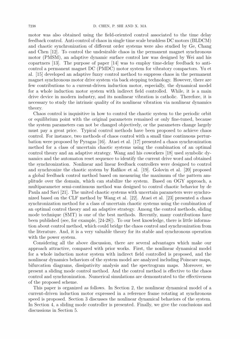
3. System Dynamics Analysis. The phase trajectory is most intuitive way to describesystem state, shown in Figure 1, when c1 = 13.67, c2 = 1.56, c3 = 0.59, c4 = 1176,c5 = 2.86, u0
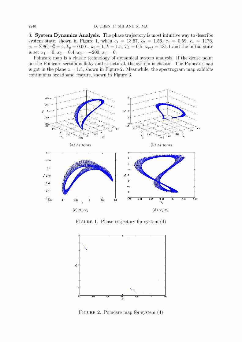
2 = 4, kp = 0.001, ki = 1, k = 1.5, TL = 0.5, ωref = 181.1 and the initial stateis set x1 = 0, x2 = 0.4, x3 = −200, x4 = 6.Poincare map is a classic technology of dynamical system analysis. If the dense point
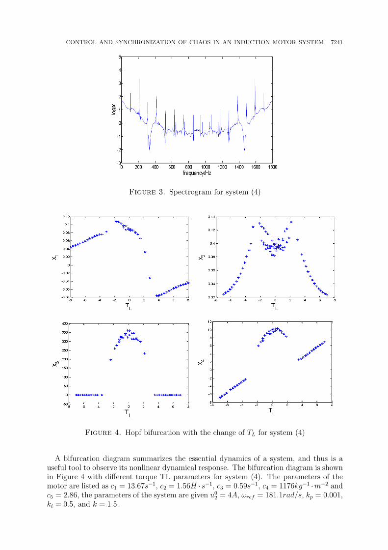
on the Poincare section is flaky and structural, the system is chaotic. The Poincare mapis got in the plane z = 1.5, shown in Figure 2. Meanwhile, the spectrogram map exhibitscontinuous broadband feature, shown in Figure 3.
(a) x1-x2-x3 (b) x1-x2-x4
(c) x1-x2 (d) x2-x4
Figure 1. Phase trajectory for system (4)
Figure 2. Poincare map for system (4)
CONTROL AND SYNCHRONIZATION OF CHAOS IN AN INDUCTION MOTOR SYSTEM 7241
Figure 3. Spectrogram for system (4)
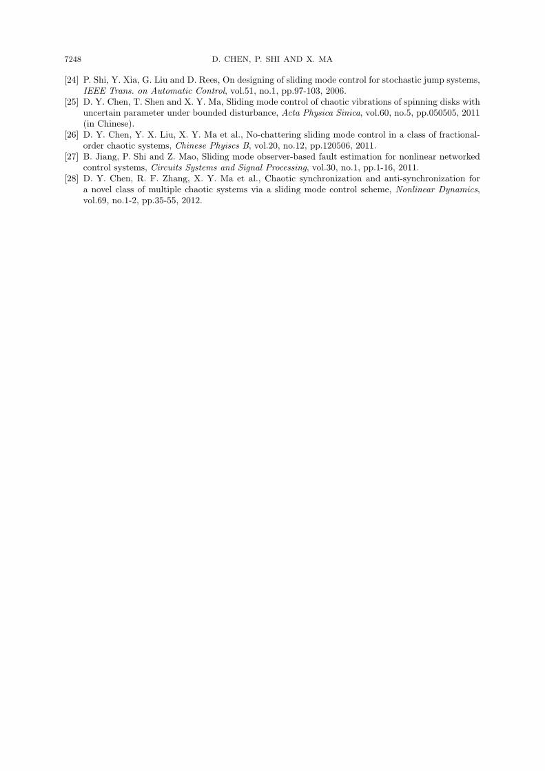
Figure 4. Hopf bifurcation with the change of TL for system (4)
A bifurcation diagram summarizes the essential dynamics of a system, and thus is auseful tool to observe its nonlinear dynamical response. The bifurcation diagram is shownin Figure 4 with different torque TL parameters for system (4). The parameters of themotor are listed as c1 = 13.67s−1, c2 = 1.56H ·s−1, c3 = 0.59s−1, c4 = 1176kg−1 ·m−2 andc5 = 2.86, the parameters of the system are given u0
2 = 4A, ωref = 181.1rad/s, kp = 0.001,ki = 0.5, and k = 1.5.

7242 D. CHEN, P. SHI AND X. MA
The equilibria of system (4) can be found by solving the following algebraic equations:
0 = −c1x1 + c2x4 − kc1u02x2x4
0 = −c1x2 + c2u02 +
kc1u02x1x4
0 = −c3x3 − c4
[c5 (x2x4 − x1u
02)− TL − c3
c4ωref
]0 = (ki − kpc3) x3 − kpc4
[c5 (x2x4 − x1u
02)− TL − c3
c4ωref
]where, c1 = 13.67, c2 = 1.56, c3 = 0.59, c4 = 1176, c5 = 2.86, u0
2 = 4, kp = 0.001, ki = 1,k = 1.5, TL = 0.5, ωref = 181.1 and the initial state is set to x1 = 0, x2 = 0.4, x3 = −200,x4 = 6.The system has three equilibria, which are respectively described as follows:O(−0.017, 0.455, 0, 0.304),E+(−0.022− 0.182 ∗ i, 0.184 + 0.021 ∗ i, 0, 0.187− 3.981 ∗ i),E−(−0.022 + 0.182 ∗ i, 0.184− 0.021 ∗ i, 0, 0.187 + 3.981 ∗ i).The system has a unique equilibrium O(−0.017, 0.455, 0, 0.304). Linearize the system
at O, and the Jacobian matrix is obtained as follows:
J0 =
−13.67 −5.12625x4 0 1.56− 5.12625x2
5.12625x4 −13.67 0 5.12625x1
13453.44 −3363.36x4 −0.59 −3363.36x2
13.45344 −3.36336x4 0.99941 −3.36336x2
=
−13.67 −1.558 0 −0.7721.558 −13.67 0 −0.087
13453.44 −1022.46 −0.59 −1530.3213.4534 −1.022 0.999 −1.530
For gaining its eigenvalues, we have:
|λI − J0| = 0
These eigenvalues at equilibrium O are respectively obtained as follows:
λ1 = 1.65 + 40.39i, λ2 = 1.65− 40.39i, λ3 = −18.98, λ4 = −13.78.
λ1, λ2 are complex conjugate pair and their real parts are positive, and λ3 and λ4 arenegative real numbers. Therefore, the equilibrium O is a saddle point. It is unstable.The other two equilibrium points E+ and E− do not belong to the real space. Thus, it
is not necessary to discuss stability of these points.The theory of dissipative systems is a basic tool to describe the system characteristics.
And dissipative analysis of system (4) is presented as follows. For system (4), it is noticedthat
∇V =∂
•x1
∂x1
+∂
•x2
∂x2
+∂
•x3
∂x3
+∂
•x4
∂x4
= − (2c1 + c3 + kpc4c5x2) < 0,
where c1 = 13.67, c3 = 0.59, c4 = 1176, c5 = 2.86, kp = 0.001 and 0.32 ≤ x2 ≤ 0.42.Obviously, system (4) can have dissipative structure, with an exponential contractionrate:
dV
dt= − (2c1 + c3 + kpc4c5x2)V.
That is, a volume element V0 is contracted by the flow into a volume elementV0e
−(2c1+c3+kpc4c5x2)t in time t. This means that each volume containing the system orbitshrinks to zero as t → ∞ at an exponential rate − (2c1 + c3 + kpc4c5x2). Therefore, all

CONTROL AND SYNCHRONIZATION OF CHAOS IN AN INDUCTION MOTOR SYSTEM 7243
system orbits are ultimately confined to some subset of zero volume, and the asymptoticmotion settles on some attractors.
4. Chaos Control, Synchronization and Numerical Simulation Results.
4.1. Controller design. Consider the drive system
Dx = Ax+ g(x) (5)
where x(t) ∈ R4 denotes the state vector of the 4-dimensional system, A ∈ R4×4 representsthe linear part of the system and g : R4 → R4 is the nonlinear part of the system.
Considering y(t) ∈ R4 as the response of state vector of the 4-dimensional system, wecan rewrite the response system as
Dy = Ay + g(y) (6)
The controller u(t) ∈ R4 is added to system (6), so it can be rewritten as:
Dy = Ay + g(y) + u(t) (7)
Here, we define the synchronization errors e = y − x. The aim is to choose a suitablecontroller u(t) ∈ R4 such that the states of the master and slave systems can reachsynchronization (i.e., lim
t→∞‖e‖ = 0, where ‖·‖ is the Euclidean norm).
Now, one sets the controller u(t) as
u(t) = u1(t) + u2(t) (8)
where u1(t) ∈ R4 is a compensation controller, and u1(t) = Dx−A(x)− g(x). u2(t) ∈ R4
is a vector function, and will be designed later. Using (8), response system (7) can berewritten as
De(t) = Ae+ g(y)− g(x) + u2(t) (9)
In accordance with the procedure of designing active controller, the nonlinear part ofthe error dynamics is eliminated by the following the following input vector:
u2(t) = g(x)− g(y) +Kw(t) (10)
Error system (9) is then rewritten as follows
De(t) = Ae+Kw(t) (11)
where K = [k1, k2, k3, k4]T is a constant gain vector and w(t) ∈ R is the control input
that satisfies
w(t) =
{w+(t)w−(t)
s(e) ≥ 0s(e) < 0
(12)
As a choice for the sliding surface, we have
s(t) = Ce (13)
where C = [c1, c2, c3, c4]T is a constant vector. For sliding mode method, the sliding
surface and its derivative must satisfy the following conditions.
s(t) = 0, s(t) = 0 (14)
One sets:
s(t) = CDe(t) = C(Ae+Kw(t)) = 0 (15)
To satisfy the above condition, the discontinuous reaching law is chosen as follows
Ds(t) = −psign(s)− rs (16)

7244 D. CHEN, P. SHI AND X. MA
where
sign(s) =
+1, s > 00, s = 0−1, s < 0
(17)
and p > 0, r > 0 are the gains of the controller.Considering (15) and (16), we have
w(t) = −(CK)−1 [C(rI + A)e+ psign(s)] (18)
Now, the total control law can be defined as follows
u(t) = Dx− Ax− g(y)−K(CK)−1 [C(rI + A)e+ psign(s)] (19)
Using (19) and (9), the error dynamics can be obtained
De = [A−K(CK)−1C(rI + A)]e−K(CK)−1psign(s) (20)
For the sliding term, a linear system is a bounded input (−K(CK)−1p, when s > 0and K(CK)−1p, when s < 0). The system (20) is stable, if |arg(eig([A−K(CK)−1C(rI+A)]))| > π/2. It can be shown that choosing appropriate K, C and r can make theerror dynamics stable. Hence, the synchronization is realized.Similarly, if the drive system (5) is modified as
Dx = 0 (21)
Thus, the response system can be controlled to the initial values of drive system. If theinitial values are changed, the controlling to any stable point can be achieved.
4.2. Numerical simulation results. The numerical simulation results are carried outto verify the applicability and effectiveness of the proposed sliding mode control method.It should be noticed that the controller is in action at t = 10. The ode45 solver of Matlabsoftware is applied to solve different equations. By taking the parameters as these inSection 3, system (4) can be rewritten as:
•x
1 = −13.67x1 + 1.56x4 − 5.1262x2x4
•x
2 = −13.67x2 + 5.1262x1x4 + 6.24•x3 = −0.59x3 − 3363.4x2x4 + 13453x1 + 694.85•x4 = 0.9994x3 − 3.3634x2x4 + 13.4534x1 + 0.6948
(22)
According to 4.1, we get
A =
−13.67 0 0 1.56
0 −13.67 0 013453 0 −0.59 013.4534 0 0.9994 0
, g =
−5.1262x2x4
5.1262x1x4 + 6.24−3363.4x2x4 + 694.85−3.3634x2x4 + 0.6948
Let system (22) with initial conditions [xd1, xd2, xd3, xd4]
T = [0, 0.4,−200, 6]T as a drivesystem, and system (22) with initial values [xr1, xr2, xr3, xr4]
T = [0.3, 0.5, 0.2, 0.4]T as aresponse system. The parameters of the controller are set as K = [−2,−6,−2,−2]T,C = [5, 5, 5, 5], r = 5, and p = 0.2. This selection of parameters results in eigenvalues(λ1, λ2, λ3, λ4) = (−2247.3,−14.072,−5,−2.1495) which are located in the stable region.

CONTROL AND SYNCHRONIZATION OF CHAOS IN AN INDUCTION MOTOR SYSTEM 7245
According to (19), the control signals are obtained as
u1 =dqr1xd
dt− 2243.0e1 + 1.4450e2 − 0.9016e3 − 1.0933e4
+ 13.670xd − 1.56wd + 5.1262yrwr − 0.0067sign(s1)
u2 =dqr2yd
dt− 6728.9e1 + 4.3350e2 − 2.7047e3 − 3.28e4
+ 13.67yd − 5.1262xrwr − 6.24− 0.02sign(s2)
u3 =dqr3zd
dt− 2243.0e1 + 1.4450e2 − 0.90157e3 − 1.0933e4
− 13453xd + 0.59zd + 3363.4yrwr − 694.85− 0.0067sign(s3)
u4 =dqr4wd
dt− 2243.0e1 + 1.4450e2 − 0.90157e3 − 1.0933e4
− 13.453xd − 0.9994zd + 3.3634yrwr − 0.6948− 0.0067sign(s4)
(23)
where e1 = xr − xd, e2 = yr − yd, e3 = zr − zd, e4 = wr − wd.The numerical simulation results are given in Figure 5. One can see, the errors con-
verge to zero immediately after the controller was applied, which implies that the chaossynchronization between the two systems is realized.
Keep the parameters of the controller fixed, while set the drive system as system (21)to investigate the effectiveness of the controller. And we still use system (23) as thecontroller. Fortunately, Figure 6 illustrates the response states, which show that theresponse states follow initial values of the drive system immediately.
5. Conclusions and Discussions. The drive system of induction motor with indirectfield controlled is studied in this paper. The system model is described, which is an au-tonomous four-order electromechanical system. In order to analyze a variety of chaotic
Figure 5. Synchronization errors between the two systems (the controlleru(t) is activated at t = 10)

7246 D. CHEN, P. SHI AND X. MA
Figure 6. The state variables of the response system in the presence ofcontroller (the controller u(t) is activated at t = 10)
phenomena, we employ several numerical techniques such as phase portrait, bifurcation di-agrams, Poincare map, balance point, Spectrogram map and dissipativity. To understandthe complex dynamics of system, some basic dynamical properties, such as equilibrium,stability are rigorously derived and studied. Chaotic attractors are first numerically ver-ified through investigating phase trajectories, bifurcation path and Poincare projectionsand dissipativity. All of the above is theoretical basis of stability of an induction motorsystem with indirect field controlled.Synchronization and control of the chaos in the induction motor system based on slid-
ing mode law is proposed. The theoretical analysis and numerical results have shownthe effectiveness of the proposed controller. Moreover, the sliding mode law is a bridgebetween chaos control and synchronization, which provides a theoretical support for itsstable and synchronous operation with the power system.In fact, the electrical devices are all nonlinear system. With the rapid development
of nonlinear science, it comes true that many nonlinear models can be described andanalyzed. Furthermore, the more and better control methods for different situationsshould be studied. For example, new controller is with fewer terms, new control methodhas better immunity against noise and uncertain parameters.
Acknowledgment. This work is partially supported by National Natural Science Foun-dation (NO. 51109180) and Talent Special Fund of North West A&F University (BJRC-2009-001). The authors also gratefully acknowledge the helpful comments and suggestionsof the reviewers, which have improved the presentation.

CONTROL AND SYNCHRONIZATION OF CHAOS IN AN INDUCTION MOTOR SYSTEM 7247
REFERENCES
[1] D. Y. Chen, Y. X. Liu, X. Y. Ma and R. F. Zhang, Control of a class of fractional-order chaoticsystems via sliding mode, Nonlinear Dynamics, vol.67, no.1, pp.893-901, 2012.
[2] J. Zhang, C. S. Zhou, X. K. Xu and M. Small, Mapping from structure to dynamics: A unified viewof dynamical processes on networks, Physical Review E, vol.82, no.2, pp.026116, 2010.
[3] D. Y. Chen, W. L. Zhao, X. Y. Ma et al., No-chattering sliding mode control chaos in Hindmarsh-Rose neurons with uncertain parameters, Computers and Mathematics with Applications, vol.61,no.8, pp.3161-3171, 2011.
[4] C. A. Kitio Kwuimy, B. Nana and P. Woafo, Experimental bifurcations and chaos in a modified self-sustained macro electromechanical system, Journal of Sound and Vibration, vol.329, no.15, pp.3137-3148, 2010.
[5] D. Y. Chen, C. Wu, C. F. Liu et al., Synchronization and circuit simulation of a new double-wingchaos, Nonlinear Dynamics, vol.67, no.2, pp.1481-1504, 2012.
[6] M. Ataei, A. Kiyoumarsi and B. Ghorbani, Control of chaos in permanent magnet synchronous motorby using optimal Lyapunov exponents placement, Physics Letters A, vol.374, no.41, pp.4226-4230,2010.
[7] Z. J. Jing, C. Yu and G. R. Chen, Complex dynamics in a permanent-magnet synchronous motormodel, Chaos, Solitons and Fractals, vol.22, no.4, pp.831-848, 2004.
[8] A. M. Harb and A. A. Zaher, Nonlinear control of permanent magnet stepper motors, Communica-tions in Nonlinear Science and Numerical Simulations, vol.9, no.4, pp.443-458, 2004.
[9] M. Zribi, A. Oteafy and N. Smaoui, Controlling chaos in the permanent magnet synchronous motor,Chaos, Solitons and Fractals, vol.41, no.3, pp.1266-1276, 2009.
[10] Z. M. Ge and J. W. Cheng, Chaos synchronization and parameter identification of three time scalesbrushless DC motor system, Chaos, Solitons and Fractals, vol.24, no.2, pp.597-616, 2005.
[11] D. O. T. Fossi and P. Woafo, Dynamical behaviors of a plate activated by an induction motor,Journal of Sound and Vibration, vol.329, no.17, pp.3507-3519, 2010.
[12] Z. M. Ge, C. M. Chang and Y. S. Chen, Anti-control of chaos of single time scale brushless DCmotors and chaos synchronization of different order system, Chaos, Solitons and Fractals, vol.27,no.5, pp.1298-1315, 2006.
[13] D. Q. Wei, X. S. Luo, B. H. Wang et al., Robust adaptive dynamic surface control of chaos inpermanent magnet synchronous motor, Physics Letters A, vol.363, no.1-2, pp.71-77, 2007.
[14] Z. Wang and K. T. Chau, Anti-control of chaos of a permanent magnet DC motor system forvibratory compactors, Chaos, Solitons and Fractals, vol.36, no.3, pp.694-708, 2008.
[15] J. P. Yu, B. Chen, H. S. Yu et al., Adaptive fuzzy tracking control for the chaotic permanent magnetsynchronous motor drive system via backstepping, Nonlinear Analysis: Real World Applications,vol.12, no.1, pp.671-681, 2011.
[16] K. Pyragas, Continuous control of chaos by self-controlling feedback, Physics Letters A, vol.170,no.6, pp.421-428, 1992.
[17] M. Ataei, A. Iromloozadeh and B. Karimi, Robust synchronization of a class of uncertain chaoticsystems based on quadratic optimal theory and adaptive strategy, Chaos, vol.20, no.4, pp.043137,2010.
[18] M. G. Wang, X. Y. Wang, Z. Z. Liu and H. G. Zhang, The least channel capacity for chaos synchro-nization, Chaos, vol.21, no.1, pp.013107, 2011.
[19] M. Rafikov and J. M. Balthazar, On control and synchronization in chaotic and hyperchaotic systemsvia linear feedback control, Communications in Nonlinear Science and Numerical Simulation, vol.13,no.7, pp.1246-1255, 2008.
[20] A. A. Golovin, Y. Kanevsky and A. A. Nepomnyashchy, Feedback control of subcritical Turinginstability with zero mode, Physical Reiview E, vol.79, no.4, pp.046218, 2009.
[21] A. S. de Paula and M. A. Savi, A multiparameter chaos control method based on OGY approach,Chaos, Solitons & Fractals, vol.40, no.3, pp.1376-1390, 2009.
[22] H. Wang, Z. Z. Han, W. Zhang and Q. Y. Xie, Synchronization of united chaotic systems withuncertain parameters based on the CLF, Nonlinear Analysis: Real World Applications, vol.10, no.2,pp.715-722, 2009.
[23] M. Ataei, A. Iromloozadeh and B. Karimi, Robust synchronization of a class of uncertain chaoticsystems based on quadratic optimal theory and adaptive strategy, Chaos, vol.20, no.4, pp.043137,2010.
7248 D. CHEN, P. SHI AND X. MA
[24] P. Shi, Y. Xia, G. Liu and D. Rees, On designing of sliding mode control for stochastic jump systems,IEEE Trans. on Automatic Control, vol.51, no.1, pp.97-103, 2006.
[25] D. Y. Chen, T. Shen and X. Y. Ma, Sliding mode control of chaotic vibrations of spinning disks withuncertain parameter under bounded disturbance, Acta Physica Sinica, vol.60, no.5, pp.050505, 2011(in Chinese).
[26] D. Y. Chen, Y. X. Liu, X. Y. Ma et al., No-chattering sliding mode control in a class of fractional-order chaotic systems, Chinese Phyiscs B, vol.20, no.12, pp.120506, 2011.
[27] B. Jiang, P. Shi and Z. Mao, Sliding mode observer-based fault estimation for nonlinear networkedcontrol systems, Circuits Systems and Signal Processing, vol.30, no.1, pp.1-16, 2011.
[28] D. Y. Chen, R. F. Zhang, X. Y. Ma et al., Chaotic synchronization and anti-synchronization fora novel class of multiple chaotic systems via a sliding mode control scheme, Nonlinear Dynamics,vol.69, no.1-2, pp.35-55, 2012.


![COEXISTENCE OF SOME CHAOS SYNCHRONIZATION TYPES IN … · 2017-05-10 · to the coexistence of synchronization types between two chaotic systems include: [25]: the approach developed](https://img.pdfslide.net/doc/110x75/5fa7432ead8f516cb56adf2d/coexistence-of-some-chaos-synchronization-types-in-2017-05-10-to-the-coexistence.jpg)