Embed Size (px)
Citation preview
CONTROL-CENTRIC SIMULATOR FOR MECHATRONICS DESIGN Case Study: Gyroscopically Stabilized Single Wheel Robot
Zhu Zhen, A. Al-Mamun and Myint Phone Naing
Corresponding author: A. Al-Mamun ([email protected]) Department of Electrical and Computer Engineering
National University of Singapore Singapore 117576
Abstract— A 3-Dimensional simulation platform developed as an aid for designing complex
mechatronics system is presented in this paper. It uses ADAMS for simulation with animation of
the dynamic behavior of the mechanism whose parts are drawn using a 3-D drawing software e.g.,
SolidWorks. The overall simulation platform integrates the 3-D simulator ADAMS with control
design software MATLAB. This integration allows the designer to adopt a control-centric approach
for designing complex mechanical structure to be used in a mechatronics system. Dynamic analysis
of single wheel robot is used in this paper as an example to illustrate its uses. The simulating
environment can easily be extended to any complex mechanical system simply by altering
SolidWorks drawings.
Index Terms—Gyrobot, ADAMS, Single wheel robot, Dynamic simulation
I. INTRODUCTION HIS article presents a control-centric approach for designing mechatronics systems. In this
approach, design of controller is not treated as an isolated problem. Rather design of the
mechanism and design of controller are considered intertwined. Two designs should be carried out
concurrently. In this paper, we outline the method of concurrent design by placing a virtual prototype
of the mechanical system under closed loop control to analyze the dynamic behaviour of the system
and thus to fine-tune the mechanical design.
Simulation is important for designing any mechatronics system that involves complex structure and
operations. Traditionally, most simulations are computer based and require mathematical modeling.
Such model is used for describing system dynamics and for finding its dynamic response. The models
are used to predict system behavior for a given set of known parameters and initial conditions.
ADAMS, which was developed for 3-D motion simulation, is integrated with
MATLAB/SIMULINK, popular software among control community, to create the control-centric
design platform. The motion simulator uses three dimensional mechanical drawings of different sub-
systems to be combined into a complex mechatronics system. This eliminates the need for deriving
complex, nonlinear mathematical models for the dynamic behaviour of the system. The simulator has
been effectively used for the analysis of dynamic behavior of the gyrobot in both open loop condition
and with closed loop controller.
ADAMS (Automatic Dynamic Analysis of Mechanical Systems) started as a general purpose
T
INTERNATIONAL JOURNAL ON SMART SENSING AND INTELLIGENT SYSTEMS, VOL. 2, NO. 2, JUNE 2009
190

program that can analyze systems undergoing large non-linear displacements while under the effect of
non-linear force and motion input. The methodology was developed by Nicolae Orlandea [1]. It can
be categorized as a general purpose numeric code utilizing a non-minimal set of co-ordinates to
develop the equations of motion. This motion simulation software analyzes complex behavior of
mechanical assemblies and thus enables users to test virtual prototypes and optimize designs without
having to build numerous physical prototypes. It uses stiff integrators to solve these equations and
sparse matrix algebra to solve the linear algebraic equations in its innermost computation loop [2].
Since its inception, significant development investments resulted in sophisticated virtual prototyping
tools for a wide range of industrial applications. Use of virtual prototyping for design and
development of a humanoid robot has been reported in a recently published article [3].
ADAMS allows users to import geometry from CAD systems or to build a solid model of the
system from scratch. We used the first approach; different parts of the gyrobot were created using
SolidWorks. These components are then transferred to ADAMS where final model is elaborated.
The gyrobot is a wheel shaped autonomous vehicle [4]-[5]. Motivation of this design is rooted in
the stability of a running bicycle and its excellent capability to maneuver. A rolling wheel has
inherent tendency of remaining upright. If such wheel is tilted, instead of falling on side, it turns
towards the side it is tilted to. Special structural design of gyrobot incorporates in it these features of
rolling wheel.
The integrated simulator platform will simplify the phases of design of a mechatronics system.
Moreover, it can be used by students and researchers alike to have an in-depth understanding of any
complex mechanism. Integration of ADAMS with MATLAB enables control engineers to complete
the design cycle without building any prototype. Simulation results can also be used to fine tune
mechanical design. Results presented in this paper include (i) open loop simulation of gyrobot using
ADAMS, and (ii) simulation of the closed loop system. The integrated system can be used for the
control-centric design of any mechatronic system simply by replacing the 3D drawings of the
mechanical structure of gyrobot with that of any complex system.
Structure and principle of gyrobot are explained briefly in Section II. Dynamic simulations of the
gyrobot presented in Section III illustrate basic principles of operation. Results of closed loop
simulation are given in Section V. Key features of the developed system and possible areas of
improvement are highlighted in the conclusion.
II. GYROBOT: MECHANICAL STRUCTURE AND MODEL Design of the gyrobot is motivated by the excellent steering capability and dynamic stability of a
moving bicycle. Stability of this special structure of autonomous vehicle and its ability to steer can be
explained using dynamics of rolling wheel as example. The angular momentum of the rolling wheel
restrains it from falling on its side. If the wheel is tilted to one side, instead of falling it turns towards
that side due the phenomenon called gyroscopic precision. These two mechanisms are exploited in
achieving stability and steering of the wheel-shaped gyrobot. Actuation required to tilt the gyrobot
Z. Zhen, A. Al-Mamun and M. P. Naing, CONTROL-CENTRIC SIMULATOR FOR MECHATRONICS DESIGN: CASE STUDY: GYROSCOPICALLY STABILIZED SINGLE WHEEL ROBOT
191

comes from the reaction to the tilting of a heavy flywheel spinning at high speed. The flywheel is
placed inside the gyorbot shell and is hung from the axle of gyrobot using a two-axis gimbal. Large
angular momentum of the flywheel adds to the dynamic stability and provides insensitivity to attitude
disturbance. As a result, even stationary gyrobot can stand upright. This special structure has
advantages in many aspects over conventional multi-wheeled autonomous vehicles. Since electronic
components are enclosed, the gyrobot is especially suitable for deployment in wet areas.
Principle of operation of the gyrobot can be explained using the schematic drawing shown in Fig. 1.
The flywheel is suspended from the axle of the gyrobot using a gimbal assembly that enables tilting of
the spinning flywheel. The flywheel is attached to the inner gimbal and is spun by the spin motor. The
tilt motor, which is attached to the outer gimbal, can tilt the inner gimbal plus fast spinning flywheel
to either side. The gimbal and flywheel structure is suspended from a platform and the axle of gyrobot
is passed through this platform. The outer shell of gyrobot is rigidly joined to the axle. Running the
drive motor makes the wheel roll; rolling speed can be controlled by controlling RPM of drive motor.
Interested readers may refer to [4]-[6] and many other references cited there for details on the
operation of a gyroscopically stabilized single wheel robot.
(a) viewed from back (b) side view
Fig. 1: Internal mechanism of gyrobot Gyrobot model drawn in SolidWorks and actual hardware are shown in Fig. 2. Size and shape of
each part are created as par size and shape of the actual component. To reduce the complexity of
model in ADAMS, only the mechanical parts are included in the SolidWorks drawing; these are the
outer wheel, the inner gimbal, the outer gimbal, the flywheel with its supporting structure. This
structure is sufficient to reflect the physical properties of gyrobot, which will be examined later. Mass,
density and frictions are defined in ADAMS/View.
(a) Solidworks drawing of gyrobot (b) Hardware of internal mechanism
Fig. 2: External view and internal mechanism of gyrobot
INTERNATIONAL JOURNAL ON SMART SENSING AND INTELLIGENT SYSTEMS, VOL. 2, NO. 2, JUNE 2009
192

III. DYNAMIC SIMULATION IN ADAMS In this section, we present simulation results to illustrate the basic operation of the gyrobot. These
open loop simulations are carried out using ADAMS only.
A. Gyrobot Model in ADAMS The ADAMS model of gyrobot is created by importing the 3D drawings in Solidworks as
parasolids file. Material, mass, density and friction are then defined. Mass and inertial are
automatically calculated. Table I lists main dynamic characteristics of the robot components for the
proposed ADAMS model.
Gyrobot model in ADAMS environment takes several aspects into account, such as gravity, contact
constraints, friction, inertial properties and reference markers, which enable good approximation of
real robot behavior. Each joint of the mechanism is defined with a particular motion. For example,
the driving joint is specified as a revolute joint so the rotation associated with this joint specifies the
rolling motion of the wheel.
TABLE I: MAIN INERTIAL DATA FOR GYROBOT MODULES Parts Mass
(kg) Ixx
(kg m2) Iyy
(kg m2) Izz
(kg m2) Wheel 0.85 2.78×10⁻² 1.582×10⁻² 1.58×10⁻² Flywheel 1.02 1.21×10⁻³ 0.65×10⁻³ 0.65×10⁻³ Shaft 0.15 1.55×10⁻³ 1.55×10⁻³ 0.69×10⁻⁶ Inner gimbal 0.75 1.54×10⁻³ 1.38×10⁻³ 3.63×10⁻⁴ Outer gimbal 1.44 7.53×10⁻³ 7.43×10⁻³ 2.13×10⁻³ Total 4.22 39.63×10⁻³ 11.17×10⁻³ 3.30×10⁻³
B. Simulation Settings Proper dynamic simulation requires an approximation of the properties of contact between ground
and wheel rim. The actual gyrobot rim is wrapped in aluminum foil and is tested on a horizontal
surface covered by aluminum plate. The friction coefficients chosen are 0.95 for the static condition
and 0.8 for the dynamic condition, in agreement with [7].
ADAMS/Solver does all the calculations required to simulate the motion. It allows different types
of integrator for a particular problem. Detailed explanation on each integrator can be found in
ADAMS/Solver documents.
For integrator setting, GSTIFF is the recommended integrator for most of the mechanical systems.
We use default integrator, formulation and corrector. One may use other integrator settings, based on
the simulation type (for models other than gyrobot) with clear understanding of integrator setting
documents on ADAMS/Solver.
One has to specify simulation frequency, internal frequency and step size. Simulation frequency is
the frequency of updating the graphic display, whereas internal frequency is closely related to the
system under study. It represents the speed at which component states are changed. Internal frequency
is very important parameter in simulation setting and other solver settings must be set in accordance
with the internal frequency.
Z. Zhen, A. Al-Mamun and M. P. Naing, CONTROL-CENTRIC SIMULATOR FOR MECHATRONICS DESIGN: CASE STUDY: GYROSCOPICALLY STABILIZED SINGLE WHEEL ROBOT
193

The flywheel is the fastest moving object in the whole structure. If flywheel frequency is Y degrees
per second (calculated based on its speed) and the desired motion of the flywheel in each step of
integration is θStep degree, then the optimal step size (Hmax) is obtained using,
StepHY θ=× max .
For example, when the flywheel speed is set to 7000 rpm or 420000 revolutions per second and the
flywheel is expected to rotate by 5° in each integration step then Hmax should be set to 5/420000.
C. Results of Open Loop Simulation Law of conservation of momentum and gyroscopic precession govern the operation of the gyrobot.
Large angular momentum of the fast-spinning, heavy flywheel aids to overcome the external
disturbance such as tilting torque caused by gravity. According to conservation of angular momentum,
the higher the spin wheel velocity, the longer the robot should be able to stand by itself.
We verify the effect of flywheel speed on the balancing the wheel by simulating the motion with
different flywheel speeds while keeping external forces, e.g., gravity unchanged. Simulations are
carried out with seven different flywheel speeds between 1000 rpm and 7000 rpm, the highest speed
of the flywheel. For each flywheel speed, simulation is done for two conditions – (a) keeping gyrobot
stationary and (b) making it roll at a speed of 30 rpm. Results are summarized in Table II. It is clearly
evident that time elapsed before the fall of gyrobot increases with increasing flywheel speed, which
conforms to the conservation of angular momentum. When the wheel rolls, its angular momentum
adds to the angular momentum of the flywheel aiding the balancing effort. It is observed that for
identical flywheel speed, time elapsed before the fall is longer when gyrobot rolls.
TABLE II: RESULTS OF STABILIZATION TEST Time Elapsed before Fall of gyrobot
(seconds) Flywheel speed (rpm) Rolling speed = 0 Rolling speed
= 30 rpm 1000 2.7 4.5 2000 2.9 13 3000 3.4 20 4000 4.5 26 5000 7.6 35 6000 13 50 7000 13.9 50
Effect of gyroscopic precession is verified using tilt test. When a torque is applied to change the
spinning axis of the fast-rotating flywheel, it rotates about the precession axis. This causes the entire
system to precess. Change in wheel lean angle (δβ) is related to the precession rate according to the
following [8],
( )[ ]gmR
ImRI axfxw γγαδβ
&&& 22 2 ++= , where,
δβ : change in lean angle of wheel from vertical position
INTERNATIONAL JOURNAL ON SMART SENSING AND INTELLIGENT SYSTEMS, VOL. 2, NO. 2, JUNE 2009
194
α& : gyrobot precession rate
γ& : gyrobot rolling speed
aγ& : flywheel spin speed
g : acceleration due to gravity
m : mass of the gyrobot
Ixw : moment of inertia of the gyrobot
Ixf : moment of inertia of the flywheel and
R : radius of the gyrobot wheel.
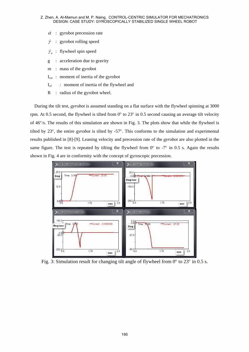
During the tilt test, gyrobot is assumed standing on a flat surface with the flywheel spinning at 3000
rpm. At 0.5 second, the flywheel is tilted from 0° to 23° in 0.5 second causing an average tilt velocity
of 46°/s. The results of this simulation are shown in Fig. 3. The plots show that while the flywheel is
tilted by 23°, the entire gyrobot is tilted by -57°. This conforms to the simulation and experimental
results published in [8]-[9]. Leaning velocity and precession rate of the gyrobot are also plotted in the
same figure. The test is repeated by tilting the flywheel from 0° to -7° in 0.5 s. Again the results
shown in Fig. 4 are in conformity with the concept of gyroscopic precession.
Fig. 3: Simulation result for changing tilt angle of flywheel from 0° to 23° in 0.5 s.
Z. Zhen, A. Al-Mamun and M. P. Naing, CONTROL-CENTRIC SIMULATOR FOR MECHATRONICS DESIGN: CASE STUDY: GYROSCOPICALLY STABILIZED SINGLE WHEEL ROBOT
195
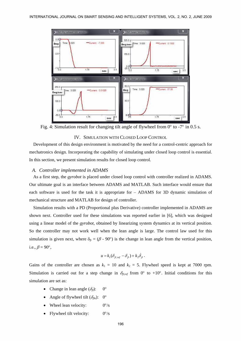
Fig. 4: Simulation result for changing tilt angle of flywheel from 0° to -7° in 0.5 s.
IV. SIMULATION WITH CLOSED LOOP CONTROL Development of this design environment is motivated by the need for a control-centric approach for
mechatronics design. Incorporating the capability of simulating under closed loop control is essential.
In this section, we present simulation results for closed loop control.
A. Controller implemented in ADAMS As a first step, the gyrobot is placed under closed loop control with controller realized in ADAMS.
Our ultimate goal is an interface between ADAMS and MATLAB. Such interface would ensure that
each software is used for the task it is appropriate for – ADAMS for 3D dynamic simulation of
mechanical structure and MATLAB for design of controller.
Simulation results with a PD (Proportional plus Derivative) controller implemented in ADAMS are
shown next. Controller used for these simulations was reported earlier in [6], which was designed
using a linear model of the gyrobot, obtained by linearizing system dynamics at its vertical position.
So the controller may not work well when the lean angle is large. The control law used for this
simulation is given next, where δβ = (β - 90°) is the change in lean angle from the vertical position,
i.e., β = 90°,
βββ δδδ &2,1 )( kku ref +−= .
Gains of the controller are chosen as k1 = 10 and k2 = 5. Flywheel speed is kept at 7000 rpm.
Simulation is carried out for a step change in δβ,ref from 0° to +10°. Initial conditions for this
simulation are set as:
• Change in lean angle (δβ): 0°
• Angle of flywheel tilt (δβa): 0°
• Wheel lean velocity: 0°/s
• Flywheel tilt velocity: 0°/s
INTERNATIONAL JOURNAL ON SMART SENSING AND INTELLIGENT SYSTEMS, VOL. 2, NO. 2, JUNE 2009
196

• Wheel velocity: 30 rpm
Simulation results with controller implemented in ADAMS are shown in Fig. 5 and Fig. 6.
Fig. 5: Lean angle with δβ,ref = 10° (controller in ADAMS)
Fig. 6: Lean angle velocity (controller in ADAMS)
B. Controller implemented in MATLAB-SIMULINK As ADAMS is meant for 3D simulation of dynamics, it has very limited capability for realizing a
controller. We created an interface between ADAMS and MATLAB/SIMULINK so that the
controller can be implemented using SIMULINK.
Closed loop responses with controller realized in SIMULINK are shown in Fig. 7 and Fig. 8. These
results are identical to those obtained with controller realized in ADAMS. Integrating ADAMS with
MATLAB let us exploit the better aspects of both. Now we are no longer restricted by the limitations
of ADAMS in implementing controllers and we can experiment with more complex controller
structures including fuzzy logic control, sliding mode control etc.
Z. Zhen, A. Al-Mamun and M. P. Naing, CONTROL-CENTRIC SIMULATOR FOR MECHATRONICS DESIGN: CASE STUDY: GYROSCOPICALLY STABILIZED SINGLE WHEEL ROBOT
197

Fig. 7: Lean angle with δβ,ref = 10° (controller in MATLAB)
Fig. 8: Lean angle velocity (controller in MATLAB)
V. CONCLUSION Dynamic simulation of gyrobot in ADAMS environment has been successfully developed. Several
tests have been carried out to verify principle of operation of the gyrobot, namely the law of
conservation of angular momentum and gyroscopic procession. Test results show that the virtual
prototype’s behavior is in accordance with the two principles and, therefore, the virtual gyrobot
created in ADAMS represents the actual mechanical system.
A controller is also implemented to strengthen the justification of building such virtual robot. The
virtual prototype can now be used for various investigations which are otherwise time-consuming or
costly.
Using the internal control template provided by ADAMS to design and implement closed loop
operation limits the flexibility of this virtual system as an effective tool. So we integrated ADAMS
with MATLAB /SIMULINK to exploit its strength.
INTERNATIONAL JOURNAL ON SMART SENSING AND INTELLIGENT SYSTEMS, VOL. 2, NO. 2, JUNE 2009
198

REFERENCES [1] N. Orlandea, Development and application of node-analogous sparsity-oriented methods for
simulation of mechanical dynamic systems, Ph.D. Thesis, University of Michigan, Ann Arbor MI,
USA, 1973
[2] R. Rampalli, “ADAMS – a sparse matrix approach to solving multi-body dynamics problems”,
NASA Workshop on Multi-Body Simulation, California Institute of Technology, USA, 1987
[3] N.E.N. Rodriguez, G. Carbone and M. Ceccarelli, “Simulation results for design and operation of
CALUMA, a new low-cost humanoid robot”, Robotica, 2008, Vol. 26, pp. 601-618
[4] H.B. Brown and Y. Xu, “A single wheel gyroscopically stabilized robot”, Proc. IEEE
International Conference on Robotics and Automation, 1996, vol. 4, pp. 3658-3663
[5] T. Saleh, H.H. Yap, Z. Zhu, A. Al-Mamun and P. Vadakkepat, “Design of a gyroscopically
stabilized single wheel robot:, Proc. of 2004 IEEE Conference on Robotics, Automation and
Mechatronics, Singapore, 1-3 Dec, 2004, vol. 2, pp. 904-908
[6] A. Al-Mamun, Z. Zhu, P. Vadakkepat and T.H. Lee, “Tracking control of the gyrobot –
gyroscopically stabilized single-wheel robot”, Proc. of the 32nd Annual Conf. of the IEEE
Industrial Electronics Society, IECON’05, Raleigh, NC, USA, 6-10 Nov, 2005
[7] Coefficient of Friction Table: http://www.roymech.co.uk/Useful_tables/Tribology/co_of_frict.htm
[8] Y. Xu, H.B. Brown and K.W. Au, “Dynamic mobility with single wheel configuration”,
International Journal of Robotics Research, Vol. 18, No. 7, July, 1999, pp. 728-738
[9] K.W. Au and Y. Xu, “Decoupled dynamics and stabilization of single wheel robot”, Proceedings
of the 1999 IEEE/RSJ International Conference on Intelligent Robots and Systems, IROS 1999,
Kyongju, Korea, 17-21 Oct, 1999, pp. 197-203
Zhu Zhen is a postgraduate student in the department of Electrical and Computer Engineering at National
University of Singapore. He is currently working in Hewlett Packard, Singapore and is in the process of
submitting his Ph.D. thesis. His research is on the design and control of a gyroscopically stabilized single wheel
robot.
A. Al-Mamun (Student’91-M’93–SM’04) graduated with the degree of B.Tech. (Honours) from the Indian
Institute of Technology, Kharagpur in 1985 and obtained Ph.D. from the National University of Singapore in
1997.
He has been working as a research engineer at the Data Storage Institute, Singapore and as a staff engineer at
Maxtor prior to joining the department of Electrical and Computer Engineering of NUS in 1999. Currently, he
is an Associate Professor there. His research interests include precision mechatronics, hard disk drive
servomechanism, intelligent control and autonomous mobile robots. He has published so far 28 papers in
premium journals and presented more than 40 papers in international conferences. He is the lead author of the
book titled “Hard Disk Drive: Mechatronics and Control”, published by CRC Press in 2006.
Myint Phone Naing is an undergraduate student in the department of Electrical and Computer Engineering
at the National University of Singapore.
Z. Zhen, A. Al-Mamun and M. P. Naing, CONTROL-CENTRIC SIMULATOR FOR MECHATRONICS DESIGN: CASE STUDY: GYROSCOPICALLY STABILIZED SINGLE WHEEL ROBOT
199