Embed Size (px)
Citation preview

Control of Generalized Contact Motion and Forcein Physical Human-Robot Interaction
Emanuele Magrini Fabrizio Flacco Alessandro De Luca
Abstract— During human-robot interaction tasks, a humanmay physically touch a robot and engage in a collaborationphase with exchange of contact forces and/or requiring coordi-nated motion of a common contact point. Under the premise ofkeeping the interaction safe, the robot controller should imposea desired motion/force behavior at the contact or explicitlyregulate the contact forces. Since intentional contacts may occuranywhere along the robot structure, the ability of controllinggeneralized contact motion and force becomes an essential robotfeature. In our recent work, we have shown how to estimatecontact forces without an explicit force sensing device, relyingon residual signals to detect contact and on the use of anexternal (depth) sensor to localize the contact point. Based onthis result, we introduce two control schemes that generalizethe impedance and direct force control paradigms to a genericcontact location on the robot, making use of the estimatedcontact forces. The issue of human-robot task compatibilityis pointed out in case of control of generalized contact forces.Experimental results are presented for a KUKA LWR robotusing a Kinect sensor.
I. INTRODUCTION
In the robotics community at large, there is great excite-ment about the recent possibility of realizing safe physicalcollaboration between human users and a new industrialgeneration of lightweight, compliant, and friendly robots [1],[2]. This technical achievement is the outcome of advances inmechanics, actuation, sensing, and control that have emergedin the last few years, from statements of basic requirements(see, e.g., [3]–[6]) to novel research results (see, e.g., [7], [8]for the original collision detection algorithm implementedin the KUKA LWR and iiwa robots). Indeed, more ofsuch scientific developments and technological transfers areneeded in order to improve further the autonomy, safety, andease of use of robotic coworkers in industrial settings and ofpersonal assistants in service applications.
Along this path, we have proposed a control architecturefor safer physical human-robot collaboration, based on ahierarchy of three consistent robot behaviors [9]. In thisframework, safety is the innermost layer with the highestpriority of execution: it implies the ability of detectingand fast reacting to accidental collisions [10] and distin-guishing between these and intentional contacts [11], [12];coexistence is the robot capability of sharing workspaces,without interfering with humans: it calls for collision avoid-ance features [13], [14], and robot operative flexibility for
The authors are with the Dipartimento di Ingegneria Informatica, Au-tomatica e Gestionale, Sapienza Universita di Roma, Via Ariosto 25,00185 Roma, Italy ({magrini,fflacco,deluca}@diag.uniroma1.it). This workis supported by the European Commission, within the FP7 ICT-287513SAPHARI project (www.saphari.eu).
modifying on line, abandoning, and resuming the originallyplanned tasks; finally, collaboration requires the robot toperform complex tasks involving direct physical interactionand coordination with humans.
One can consider different possible collaborative taskswhere physical human-robot interaction occurs: carrying aheavy payload, handing over objects, manipulating limpmaterials, holding firmly a part while the partner is operatingon it, and so on. In most cases, regulation of the forcesexchanged at the contact is needed and/or accurate control ofrelative motion while keeping in place the original contact.As additional convenient features, whole-body manipulationshould be possible, with single or multiple contacts occurringanywhere along the robot structure, and a minimum amountof extra sensing should be requested, in particular withoutthe need of a F/T sensor at the wrist or of distributed tactilesensing for the measurement of contact/interaction forces.
In [15], a method has been developed for estimating theinteraction forces (in direction and intensity) during dynamiccontacts between a robot and a human, with no explicitforce/torque sensing. The method is based on the integrateduse of model-based residual signals that detect the occurrenceof collisions [8] and of one or more external RGB-D sensors(e.g., Kinects) to approximately localize the contact point onthe surface of the robot links. This ‘virtual force sensor’ wasshown to perform with reasonably good estimation accuracy.Its output has been used already in a series of human-robot interaction experiments based on an admittance controlscheme defined at the contact point.
In this paper, we illustrate further the use of the estimatedcontact forces for the design of two human-robot interactioncontrollers that extend the impedance control method [16]and the direct force control method [17], respectively to thecase of generic contact locations on the robot. For this reason,we collectively denote this approach as generalized contactmotion and force control.
While direct force control needs always a measure (or anestimate) of the contact force, standard joint or Cartesianimpedance control laws require a force measure only if thenatural robot inertia (at the proper level) has to be changedto a desired one. When the robot inertia is left unchanged,force sensing is no longer required (the term compliancecontrol should be used then). The same situation holds truealso for our generalized contact impedance control laws,simply replacing actual measurements with the use of forceestimates (see also Fig. 1).
When realizing a force control law at the contact level,task compatibility issues may arise, mainly due to the
2015 IEEE International Conference on Robotics and Automation (ICRA)Washington State Convention CenterSeattle, Washington, May 26-30, 2015
978-1-4799-6922-7/15/$31.00 ©2015 IEEE 2298

m!!k!
!d!
!"
m! !k
!
!d!
!"
m !
!k !
!d ! ! "
Fc
m!
!F!
!k!
!d!
Fc⇒
!
ˆ F c
!"#$%&!"#$%&'($)'$$%*)+,!'-)-,./0$)*$'*,.*)
'"$%()%&#,!'-)!"#$%&'($)1!-2,0-)3,.($4-,./0$)*$'*!'56))
1!-2)$*7"&7,'),3)-2$)(,'-&(-)3,.($)
m!!F!
!k!
!d!
Fc
'(*%+,#($&!"#$%&'($)'$$%*)849)1.!*-)*$'*,.)
Fig. 1. A schematic comparison of impedance control schemes for a fullyrigid robot arm, when a desired mass-spring-damper behavior is imposedat the joint-level, at the Cartesian-level, or at the proposed contact-level,in response to a contact force F c. The estimated contact force bF c can beobtained with the method in [15]).
generality of the possible locations of the contact point. Afirst reason follows from the arguments already presentedin [15]. When contacts occur on a link close to the robotbase, the estimation method may have too little informationto recover a complete estimate of the applied contact force(in particular, the contact Jacobian may not be full rank). Thesecond reason is even more fundamental, and refers to thetype of engaged human-robot contact and its compatibilitywith the specification of a desired contact force. A completespecification of three independent scalar references for thecontact force may be incompatible with the way the humanis pushing on the robot. The situation is similar to defining acorrect task frame in hybrid force/motion control [18], [19,Chap. 9.6–7]: the robot cannot control forces along contactdirections where the human is not providing a reaction.
While the contact admittance control scheme in [15]specifies joint velocity references in response to estimatedcontact forces, and relies upon low-level servo loops fortheir execution, the two control designs presented in thispaper generate torque commands, and assume thus a torque-controlled robot (viz., motor currents can be imposed). Inaddition, an accurate robot dynamic model will be needed forcontrol implementation. All developments in the paper arepresented for rigid robot manipulators. Accordingly, no jointtorque sensors are used (nor needed) and the ‘virtual forcesensor’ concept and the associated contact force/impedancecontrollers can be implemented using only the joint encodersas proprioceptive sensing.
On the other hand, the presented control experimentshave been performed on a KUKA LWR where the use ofharmonic drive introduces joint elasticity [20]. In practice,however, the control implementation for this robot is fully
transparent with respect to the presence of compliant joints.The user defined torque-controlled modality of the FastRe-searchInterface (FRI) [21] implements the torque controlleroriginally proposed in [22], and allows to use the availablejoint torque sensors both for residual computation and forcontrol. Moreover, for all model-based computations we haveused our own identified dynamic model of the LWR linkdynamics [23].
The paper is organized as follows. Section II sets thenotation and includes a short summary on the contact forceestimation method [15] used in the remainder of the paper.Section III recaps in a compact way the standard impedanceand direct force control laws for a single mass subject to anexternal contact force. The generalization of these controlschemes to handle contact situations occurring at a genericpoint of a multi-dof robot manipulator is detailed in Sec. IV.Section V reports on several experimental results obtainedwith the proposed control methods during physical human-robot interaction with a KUKA LWR 4 robot and a Kinectsensor.
II. PRELIMINARIES
For a robot manipulator having n serial joints, withassociated generalized coordinates q ∈ Rn, assume that amotion/force interaction task is defined for a contact pointxc ∈ R3 whose direct kinematics map is given by xc =f(q). Differentiating this twice w.r.t. time yields
xc = Jc(q)q + Jc(q)q, (1)
where Jc = ∂f(q)/∂q is the 3×n contact Jacobian matrix.Note that if the contact point is located on link k (k =1, . . . , n), the last n − k columns of Jc will be identicallyzero. In most cases, the robot is redundant respect to thegiven interaction task, being k > 3.
At a given robot state (q, q), all joint accelerations asso-ciated to a desired acceleration xc of the contact point canbe written as
q = J#c (xc − Jcq) + P cq0, (2)
where J#c is a n × 3 generalized inverse of the contact
Jacobian, q0 ∈ Rn is an arbitrary joint acceleration, andP c = I − J#
c Jc is a projector in the null space of Jc.The dynamic model of a rigid manipulator interacting with
the (human) environment at a robot point xc is given by
M(q)q +C(q, q)q + g(q) = τ + JTc (q)F c, (3)
with positive definite inertia matrix M , Coriolis and cen-trifugal velocity terms Cq (factorized by the Christtoffelsymbols), gravitational terms g, control torque τ ∈ Rn,and joint torque τ c = JT
c (q)F c resulting from the contactinteraction force F c ∈ R3. We will use also the compactnotation n(q.q) = C(q, q)q + g(q).
In the framework of operational space control [18], it hasbeen shown that using the inertia-weighted pseudoinverseas the generalized inverse in (2) guarantees consistency of
2299

the transformation of task forces in the robot dynamics. Theinertia-weighted pseudoinverse of contact Jacobian is
J#c,M = M−1JT
c (JcM−1JT
c )−1. (4)
In the following, to simplify notation, each pseudoinverseJ#
c is to be intended as the inertia-weighted one given by (4).
A. Contact force estimation
The residual vector r ∈ Rn for a robot with dynamics (3)is defined as [7]
r(t) = KI
(p−
∫ t
0
(τ +CT (q, q)q − g(q) + r
)ds
),
(5)where p = M(q)q is the generalized momentum of therobot and KI > 0 is a diagonal gain matrix. The dynamicevolution of r has the stable, first-order filter structure
r = KI(τ c − r).
Thus, for sufficiently large gains, we can assume that
r ' τ c = JTc (q)F c. (6)
Equation (6) forms the basis for the estimations of theunknown contact force F c ∈ R3. Using external sensing,the location of the contact point xc can be determined, andthus the associated contact Jacobian Jc can be computed.Depending on which link in the kinematic chain is involvedin the contact, (6) may consist of a square, under-, or over-determined linear system. In any case, the contact force isestimated by pseudoinversion as
F c =(JT
c (q))#
r. (7)
Indeed, the estimate F c will be limited only to those compo-nents of F c that can be detected by the residual r, namelythose contact forces that do not belong to the null spaceN (JT
c (q)). For further details and for the analysis of caseswhen the contact Jacobian is not full rank, see [15].
Fig. 2. A view of the result of the on-line estimation of the contact force
III. IMPEDANCE AND FORCE CONTROLFOR A SINGLE MASS
As an introduction to the control design for the generalmulti-dof robotic case, consider first a very simple 1-dofexample. As shown in Fig. 3, a single mass m moves ona frictionless horizontal plane under the action of a controlforce f and of a contact force fc. The dynamic equation is
mx = f + fc. (8)
Fig. 3. A mass m subject to a control force f and a contact force fc.
A. Impedance control
The ‘inverse dynamics’ control law
f = ma− fc, (9)
transforms system (8) into the double integrator
x = a. (10)
The auxiliary input a has to be designed so that the controlledmass m, under the action of the contact force fc, matches thebehavior of an impedance model characterized by a desired(apparent) mass md > 0, desired damping kd > 0, anddesired stiffness kp > 0, all with respect to a smooth motionreference xd(t), or
md (x− xd) + kd (x− xd) + kp (x− xd) = fc. (11)
This is obtained by using the control force
f =m
md(xd + kd (xd − x) + kp (xd − x))+
(m
md− 1)fc.
(12)For k2
d < 4kpmd, the second-order linear system (11) ischaracterized by a pair of asymptotically stable complexpoles with natural frequency and damping ratio given by
ωn =√kp
md, ζ =
kd
2√kpmd
. (13)
Reducing the desired mass md, for given values of stiffnessand damping, will increase both the angular frequency andthe damping ratio, and thus improve transients. On the otherhand, for a given mass, an increase of the stiffness kp shouldbe accompanied by an increase of the damping kd in orderto prevent more oscillatory transients.
If the desired mass equals the natural (original) mass, i.e.,md = m, a measure of the contact force fc is no longerneeded in the impedance controller (12) —which is thenalso called a compliance control law, since the main designparameter left is the desired stiffness kp. In particular, for
2300

regulation tasks (with xd(t) = xd = constant) the control lawcollapses just to a PD action on the position error e = xd−x,
f = kp (xd − x)− kdx. (14)
The system will converge to x = xd if and only if there isno contact force. With fc 6= 0 but constant, there will beconvergence to the closed-loop equilibrium xe satisfying
kp(xd − xe) + fc = 0 ⇒ xe = xd +fc
kp. (15)
B. Force control
If we desire to control directly the contact force to adesired (possibly, constant) value fd, it is necessary to builda force error ef = fd − fc into the control law. After usingeq. (9), define the auxiliary input a as
a =1md
(kf (fd − fc)− kdx) (16)
with force error gain kf > 0 and velocity damping kd > 0.The associated control force is then
f =m
md(kf (fd − fc)− kdx)− fc. (17)
A contact force measure is always needed in this case, evenif we choose md = m. The closed-loop system becomes
mdx+ kdx = kf (fd − fc), (18)
which shows that the force error ef goes to zero if a constantcontact force is applied. However, the actual position x = xe
reached at the equilibrium is not known a priori, and willdepend on the actual history of the external contact force.
IV. GENERALIZED CONTACT MOTION AND FORCECONTROL FOR ROBOTS
We extend here the control design results of Sec. III to ageneric robot contact point xc of a robot manipulator, andconsider also the use of the contact force estimation F c, asprovided by (7), in place of the real measurement, each timethis will be needed.
A. Impedance control
Starting from robot model (3), and dropping from nowon dependencies for the sake of compactness, consider theinverse dynamics control law
τ = Ma+ n− JTc F c, (19)
where F c is the estimated contact force. In ideal designconditions, the above control law realizes a feedback lin-earization, leading to a system of double integrators q = a.The auxiliary control input a is chosen so as to imposea mechanical impedance model between the (estimated)contact forces F c and the motion of the contact point xc, or
Md(xc− xd)+Kd(xc− xd)+Kp(xc−xd) = F c, (20)
being Md > 0 the desired inertia matrix, Kd > 0 thedesired damping matrix, Kp > 0 the desired stiffness matrix(very often, these matrices are taken as diagonal), and xd(t)the smooth desired trajectory of the contact point. Solving for
xc from (20) and using (2), the control input a is obtainedas
a=J#cM
−1d
(Mdxd+Kde+Kpe−MdJcq+F c
)+P q0,
(21)with contact position error e = xd−xc. Thus, the resultingtorque control input is
τ =MJ#c M
−1d
(Mdxd +Kde+Kpe−MdJcq + F c
)+MPq0 + n− JT
c F c.(22)
In (22), observe that the contribution of F c is given by
τ = . . . +(MJ#
c M−1d − J
Tc
)F c. (23)
As expected, when choosing the desired inertia matrix Md
equal to the natural Cartesian inertia of the robot at thecontact point, also the estimation of the contact forces F c
will no longer be needed. At a given configuration q, thenatural inertia of the robot at a generic contact point is
Md =(JcM
−1JTc
)−1
. (24)
By using (4), it is easy to see that MJ#c M
−1d − JT
c = 0.Whenever we desire to impose a different inertial behaviorat the contact, e.g., so as to achieve different behaviors indifferent directions of the operative space, we shall make useof the contact force estimate F c.
B. Force control
The impedance method realizes only an indirect control ofthe forces exchanged during the interaction with the human,dynamic balancing with the desired position xc of the contactpoint. The development of a direct controller for the contactforce is crucial for collaborative tasks that needs accurateexecution in uncertain conditions.
With the reference to (19), choose in place of the auxiliarycommand (21), the following acceleration
a = J#c M
−1d
(Kf (F d − F c)−Kdxc −MdJcq
)+P q0,
(25)where F d is the desired force at the contact point, the contactforce error is ef = F d− F c, and Kf > 0 is the force errorgain matrix. Replacing (25) in (19), the final torque controlinput is
τ =MJ#c M
−1d
(Kfef −Kdxc −MdJcq
)+MPq0 + n− JT
c F c.(26)
Similarly to (18), the closed-loop system is described by
Mdxc +Kdxc = Kf (F d − F c), (27)
which shows again that the force error should go to zerowhenever a constant contact force is applied. Nonetheless,the issue of task compatibility remains open. In the aboveexpression of the control law for the human-robot contactforces, the specification of the desired force F d is apparentlyan unconstrained one. We shall see in the experiments that
2301

a careful choice of F d should be made so as to avoidinconsistent and drifting behavior of the robot, with seriousconsequences for safety.
V. EXPERIMENTAL RESULTS
Dynamic human-robot interaction experiments using theproposed controllers have been performed on a KUKA LWR4. The workspace is monitored by a Microsoft Kinect depthsensor, positioned at a distance of 1.7 m behind the robotand at a height of 1.1 m w.r.t. the robot base frame. TheKinect provides 640× 480 depth images at 30 Hz rate. Allalgorithms are executed on a quad-core CPU. The completeprocess of contact force estimation and motion and/or forcecontrol run on the robot at 5 ms cycle time.
With reference to the impedance control law (22), definexd = xc(tc) ∈ R3 as the initial (and constant) positionof the contact point when the interaction with the humanbegins at t = tc. The desired velocity and acceleration areset then to zero, xd = xd = 0. Due to the redundancy of thisrobot with respect to many tasks, a null-space accelerationvector has been chosen as q0 = −KN q, with KN > 0, inorder to bound/damp out self-motion movement of the arm.Finally, recall that the KUKA LWR 4 has a built-in gravitycompensation. Thus, the actual impedance control law usedto command the robot was
τ =MJ#c M
−1d
(Kpe−Kdxc −MdJcq + F c
)−MPKN q +Cq − JT
c F c.(28)
Similarly for the force control law it is
τ =MJ#c M
−1d
(Kfef −Kdxc −MdJcq
)−MPKN q +Cq − JT
c F c.(29)
All experiments presented in this paper are recorded inthe accompanying video clip. The plots can be even betterappreciated when looking in parallel at the video.
A. Impedance control with natural contact inertia
In the first experiment, the human pushes the robot atdifferent contact points and on different links, as shown inthe snapshot of Fig. 4. The control law is given by (28), withthe desired inertia matrix at the contact chosen equal to (24).The other impedance parameters were set to Kd = 80 · I3,Kp = 500·I3, andKN = 20·I7, where Ik denotes the k×kidentity matrix. Figure 5 shows the behavior of the residualvector, of the contact force estimate, and of the Cartesianposition error of the contact point with respect to its initialposition xd = xc(tc).
B. Impedance control with modified contact inertia
In this experiment, the impedance scheme (28) was usedagain during the human-robot interaction. However, the de-sired inertia matrix at the contact point was set to
Md =
20 0 00 3 00 0 10
,
!"
#"
$"
Fig. 4. The set-up and the Cartesian reference frame for the contactimpedance control experiments. The color of the X , Y , and Z axes arethe same used for the associated components in the following plots.
0 2 4 6 8 10 12
−15
−10
−5
0
5
10
15
Residual
[Nm]
r1 r2 r3 r4 r5 r6 r7
0 2 4 6 8 10 12−60
−40
−20
0
20
40
60
Force
[N]
Fc,x Fc,y Fc,z
0 2 4 6 8 10 12−0.08
−0.06
−0.04
−0.02
0
0.02
0.04
0.06
Time [s]
Error
[m]
exey
ez
Fig. 5. Contact impedance control with desired inertia matrix at the contactequal to the natural one. Residual vector components [top]. Estimated con-tact force components [center]. Contact position error components [bottom].
i.e., different from the natural one (which was also coupled).Non-uniform values were chosen on the diagonal, so as toobtain different behaviors along the three Cartesian axes –see also Fig. 4. To enhance this effect, the human pushes therobot always on link 6, although in different directions. Theother impedance parameters used were the same as in Sec. V-A. In this case, the estimated contact forces F c are neededby the control law in order to obtain the desired mass-spring-damper system. Figure 6 shows the same quantities of theprevious impedance control experiment. When the contact isinitially detected, the robot will move the contact point with adynamics that depends on the direction of the external force.When the hand is removed, the robot brings back the contactpoint to the original initial position. As shown in Fig. 6 (third
2302

plot), the error returns closer to zero on the y axis, whereMd,y = 3. By increasing the desired inertia, the error naturalfrequency and damping decrease, as indicated by (13), andtransients will worsen (see, e.g., the x axis at t = 15 s).
0 5 10 15 20−30
−20
−10
0
10
20
30
Residual
[Nm]
r1 r2 r3 r4 r5 r6 r7
0 5 10 15 20−80
−60
−40
−20
0
20
40
60
80
Force
[N]
Fc,x Fc,y Fc,z
0 5 10 15 20−0.2
−0.15
−0.1
−0.05
0
0.05
0.1
Time [s]
Error
[m]
exeyez
Fig. 6. Contact impedance control with modified inertia matrix atthe contact. Residual vector components [top]. Estimated contact forcecomponents [center]. Contact position error components [bottom].
C. Contact force control with possible drift effects
The purpose of this experiment was to show that it ishighly not recommended to try to regulate human-robot con-tact forces at arbitrary values and in multiple fixed directionsof the Cartesian space. When the human does not push orresist along a direction where a non-zero force referencehas been specified, the robot typically drifts in space inthe attempt to regulate the incompatible desired force. Thiscould be dangerous because an unexpected movement occur,through which the robot may collide with the human. Withthis in mind, the parameters were set to Kd = 10.5 · I3,Kf = 4.1 · I3, KN = 15 · I7, and the desired contact forcewas chosen as F d =
(0 15 0
)T, i..e., only in the Y
direction. Figure 8 shows the behavior of the residual vectorr, of the contact force estimate Fc, and of the Cartesianvelocity xc of the contact point. When the human pushesthe robot (on link 6) along the Y axis, the robot reactsproperly and regulate the force components to the desiredlevel. However, when the human pushes the robot along theX direction, a drift occurs along the Y direction, as shownin Fig. 8 (e.g., at t = 14.8 s).
D. Contact force control with task compatibility
The contact force control scheme (29) was used in thisinteraction control experiment, where the human pushes the
!"
#"
$"
Fig. 7. The set-up and the Cartesian reference frame for the contact forcecontrol experiments. On the left, the human is pushing along the Y directionwhere a non-zero desired force is specified (Fy,d = 15 N). On the right, adrift effect occurs due the absence of a human reaction in the Y direction(a force is applied approximately along the X direction only).
0 2 4 6 8 10 12 14 16 18 20
−8
−6
−4
−2
0
2
4
6
8
Residual[N
m]
r1 r2 r3 r4 r5 r6 r7
0 2 4 6 8 10 12 14 16 18 20−5
0
5
10
15
20
Force
[N]
Fc,x Fc,y Fc,z Fd,y
0 2 4 6 8 10 12 14 16 18 20−1
−0.5
0
0.5
1
Time [s]
Velocity
[m/s]
xc,x xc,y xc,z
Fig. 8. Contact force control with drift motion due to task incompatibility.Components of the residual vector [top]. Modulus of the estimated contactforce [center]. Components of the Cartesian contact velocity xc [bottom].When the human pushes along the Y direction, regulation occurs (see thefirst 12 s). The human pushing along the X direction (where Fx,d = 0) willbe accommodated by a robot retraction, whereas the absence of a humanreaction in the Y direction (where Fy,d = 15 N) does not allow forceregulation and generates large velocity drifts in that same direction (see thelast 6 s in the third plot).
robot successively on link 3, link 5, and then link 6 (seethe associated behaviors of the residuals in Fig. 9, [top]).To avoid incompatibility with the human, only the norm ofthe desired contact force F d has been, here as a constant‖F d‖ = 15 N. However, F d will change direction accordingto the human-robot contact type, and being always alignedwith the estimated contact force vector which may now varywithout any restriction. We will have thus,
Fd,x = 15Fc,x
‖F c‖, Fd,y = 15
Fc,y
‖F c‖, Fd,z = 15
Fc,z
‖F c‖.
2303
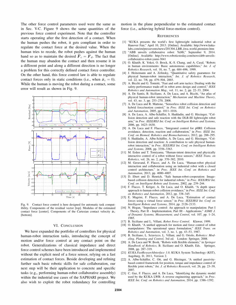
The other force control parameters used were the same asin Sec. V-C. Figure 9 shows the same quantities of theprevious force control experiment. Note that the controllerstarts operating after the first detection of a contact. Whenthe human pushes the robot, it gets compliant in order toregulate the contact force at the desired value. When thehuman tries to recede, the robot pushes against the humanhand so as to maintain the desired F c = F d. The fact thatthe human may abandon the contact and then resume it ina different point and along a different direction is no longera problem for this correctly defined contact force controller.On the other hand, this force control law is able to regulatecontact forces only in static conditions (i.e., when xc = 0).While the human is moving the robot during a contact, someerror will result as shown in Fig. 9.
0 5 10 15 20 25 30 35 40
−8
−6
−4
−2
0
2
4
6
8
Residual
[Nm]
r1 r2 r3 r4 r5 r6 r7
0 5 10 15 20 25 30 35 40
0
5
10
15
20
Force
[N]
∥
∥
∥Fc
∥
∥
∥
‖Fd‖
0 5 10 15 20 25 30 35 40−0.5
−0.4
−0.3
−0.2
−0.1
0
0.1
0.2
Time [s]
Velocity
[m/s]
xc,x xc,y xc,z
Fig. 9. Contact force control is here designed for automatic task compat-ibility. Components of the residual vector [top]. Modulus of the estimatedcontact force [center]. Components of the Cartesian contact velocity xc
[bottom].
VI. CONCLUSION
We have expanded the portfolio of controllers for physicalhuman-robot interaction tasks, introducing the concept ofmotion and/or force control at any contact point on therobot. Generalizations of classical impedance and directforce control schemes have been introduced and implementedwithout the explicit need of a force sensor, relying on a fastestimation of contact forces. Beside developing and refiningfurther such basic robotic skills for safe collaboration, ournext step will be their application to concrete and specifictasks (e.g,, performing human-robot collaborative assembly)within the industrial use cases of the SAPHARI project. Wealso wish to exploit the robot redundancy for controlling
motion in the plane perpendicular to the estimated contactforce (i.e., achieving hybrid force-motion control).
REFERENCES
[1] “KUKA presents the world’s first lightweight industrial robot atHanover Fair,” April 10, 2013. [Online]. Available: http://www.kuka-labs.com/en/pressevents/news/201304 LBR iiwa world premiere.htm
[2] “ABB unveils collaborative robot: YuMi,” September 9, 2014.[Online]. Available: http://www.roboticstoday.com/news/abb-unveils-collaborative-robot-yumi-3041
[3] O. Khatib, K. Yokoi, O. Brock, K.-S. Chang, and A. Casal, “Robotsin human environments: Basic autonomous capabilities,” Int. J. ofRobotics Research, vol. 18, no. 7, pp. 684–696, 1999.
[4] J. Heinzmann and A. Zelinsky, “Quantitative safety guarantees forphysical human-robot interaction,” Int. J. of Robotics Research,vol. 22, no. 7/8, pp. 479–504, 2003.
[5] A. Bicchi and G. Tonietti, “Fast and soft arm tactics: Dealing with thesafety-performance trade-off in robot arms design and control,” IEEERobotics and Automation Mag., vol. 11, no. 2, pp. 22–33, 2004.
[6] A. De Santis, B. Siciliano, A. De Luca, and A. Bicchi, “An atlas ofphysical human-robot interaction,” Mechanism and Machine Theory,vol. 43, no. 3, pp. 253–270, 2008.
[7] A. De Luca and R. Mattone, “Sensorless robot collision detection andhybrid force/motion control,” in Proc. IEEE Int. Conf. on Roboticsand Automation, 2005, pp. 1011–1016.
[8] A. De Luca, A. Albu-Schaffer, S. Haddadin, and G. Hirzinger, “Col-lision detection and safe reaction with the DLR-III lightweight robotarm,” in Proc. IEEE/RSJ Int. Conf. on Intelligent Robots and Systems,2006, pp. 1623–1630.
[9] A. De Luca and F. Flacco, “Integrated control for pHRI: Collisionavoidance, detection, reaction and collaboration,” in Proc. IEEE Int.Conf. on Biomed. Robotics and Biomechatronics, 2012, pp. 288–295.
[10] S. Haddadin, A. Albu-Schaffer, A. De Luca, and G. Hirzinger, “Col-lision detection and reaction: A contribution to safe physical human-robot interaction,” in Proc. IEEE/RSJ Int. Conf. on Intelligent Robotsand Systems, 2008, pp. 3356–3363.
[11] M. Erden and T. Tomiyama, “Human-intent detection and physicallyinteractive control of a robot without force sensors,” IEEE Trans. onRobotics, vol. 26, no. 2, pp. 370–382, 2010.
[12] M. Geravand, F. Flacco, and A. De Luca, “Human-robot physicalinteraction and collaboration using an industrial robot with a closedcontrol architecture,” in Proc. IEEE Int. Conf. on Robotics andAutomation, 2013, pp. 4000–4007.
[13] D. Ebert and D. Henrich, “Safe human-robot-cooperation: Image-based collision detection for industrial robots,” in Proc. IEEE/RSJ Int.Conf. on Intelligent Robots and Systems, 2002, pp. 239–244.
[14] F. Flacco, T. Kroger, A. De Luca, and O. Khatib, “A depth spaceapproach to human-robot collision avoidance,” in Proc. IEEE Int. Conf.on Robotics and Automation, 2012, pp. 338–345.
[15] E. Magrini, F. Flacco, and A. De Luca, “Estimation of contactforces using a virtual force sensor,” in Proc. IEEE/RSJ Int. Conf. onIntelligent Robots and Systems, 2014, pp. 2126–2133.
[16] N. Hogan, “Impedance control: An approach to manipulation: Part I- Theory, Part II - Implementation, Part III - Applications,” ASME J.of Dynamic Systems, Measurement, and Control, vol. 107, pp. 1–24,1985.
[17] B. Siciliano and L. Villani, Robot Force Control. Kluwer, 1999.[18] O. Khatib, “A unified approach for motion and force control of robot
manipulators: The operational space formulation,” IEEE Trans. onRobotics and Automation, vol. 3, no. 1, pp. 43–53, 1987.
[19] B. Siciliano, L. Sciavicco, L. Villani, and G. Oriolo, Robotics: Mod-eling, Planning and Control, 3rd ed. London: Springer, 2008.
[20] A. De Luca and W. Book, “Robots with flexible elements,” in SpringerHandbook of Robotics, B. Siciliano and O. Khatib, Eds. Springer,2008, pp. 287–319.
[21] KUKA.FastResearchInterface 1.0, KUKA System Technology (KST),Augsburg, D, 2011, Version 2.
[22] A. Albu-Schaffer, C. Ott, and G. Hirzinger, “A unified passivity-based control framework for position, torque and impedance control offlexible joint robots,” Int. J. of Robotics Research, vol. 26, pp. 23–39,2007.
[23] C. Gaz, F. Flacco, and A. De Luca, “Identifying the dynamic modelused by the KUKA LWR: A reverse engineering approach,” in Proc.IEEE Int. Conf. on Robotics and Automation, 2014, pp. 1386–1392.
2304