Embed Size (px)
Citation preview

BAU Journal - Science and Technology BAU Journal - Science and Technology
Volume 2 Issue 1 ISSN: 2706-784X Article 10
December 2020
CONTROL OF MR DAMPER USING ANFIS AND PID CONTROLLER CONTROL OF MR DAMPER USING ANFIS AND PID CONTROLLER
FOR OPTIMUM VEHICLE RIDE COMFORT FOR OPTIMUM VEHICLE RIDE COMFORT
Mohammad Faisal Yakhni Eng., Faculty of Engineering, Beirut Arab University, Beirut, Lebanon, [email protected]
Mohamad Ali Assisstant Professor, Faculty of Engineering, Beirut Arab University, Beirut, Lebanon, [email protected]
Mohamed El-Gohary Assisstant Professor, Faculty of Engineering, Beirut Arab University, Beirut, Lebanon, [email protected]
Follow this and additional works at: https://digitalcommons.bau.edu.lb/stjournal
Part of the Acoustics, Dynamics, and Controls Commons, Applied Mechanics Commons, Controls and
Control Theory Commons, and the Navigation, Guidance, Control, and Dynamics Commons
Recommended Citation Recommended Citation Yakhni, Mohammad Faisal; Ali, Mohamad; and El-Gohary, Mohamed (2020) "CONTROL OF MR DAMPER USING ANFIS AND PID CONTROLLER FOR OPTIMUM VEHICLE RIDE COMFORT," BAU Journal - Science and Technology: Vol. 2 : Iss. 1 , Article 10. Available at: https://digitalcommons.bau.edu.lb/stjournal/vol2/iss1/10
This Article is brought to you for free and open access by Digital Commons @ BAU. It has been accepted for inclusion in BAU Journal - Science and Technology by an authorized editor of Digital Commons @ BAU. For more information, please contact [email protected].

CONTROL OF MR DAMPER USING ANFIS AND PID CONTROLLER FOR OPTIMUM CONTROL OF MR DAMPER USING ANFIS AND PID CONTROLLER FOR OPTIMUM VEHICLE RIDE COMFORT VEHICLE RIDE COMFORT
Abstract Abstract Suspension system design is an important challenging duty that facing car manufacturers, so the challenge has become to design the best system in terms of providing ride comfort and handling ability under all driving situations. The goal of this paper is to provide assistance in enhancing the effectiveness of the suspension system. A full car model with eight Degrees Of Freedom (DOF) was developed using MATLAB/Simulink. Validation of the Simulink model was obtained. The model was assumed to travel over a speed hump that has a half sine wave shape and amplitude that changing from 0.01 to 0.2 m. The vehicle was moving with variable speeds from 20 to 120 km/h. Magneto Rheological (MR) damper was implanted to the model to study its effect on ride comfort. Adaptive-Network-based Fuzzy Inference System (ANFIS) was used to find the optimum voltage value applied to the MR damper, to skip the hump at least displacement. This network uses road profile and the vehicle speed as inputs. A Proportional Integral Derivative (PID) controller has been used to deal with potential disturbances that may affect the obtained voltage by the ANFIS. A comparison of the results for passive suspension system and model with MR damper, and system with and without PID controller, are illustrated. Results show that the MR damper gives significant improvements of the vehicle ride performance over the passive suspension system, and the PID increases the effectiveness of the system to skip the disturbance with minimal damage.
Keywords Keywords Ride comfort, eight DOF full car model, MR damper, ANFIS, PID
This article is available in BAU Journal - Science and Technology: https://digitalcommons.bau.edu.lb/stjournal/vol2/iss1/10
1. INTRODUCTION The function of the suspension is to protect vehicle from the vibrations that receives when
traveling on a rough road surface. In general based on the damper utilized and the actuator added
to the suspension framework, this system can be sorted or classified in light on the external
power input into three types, each one of them has its own advantages and disadvantages, which
are: passive suspension, semi active and active suspension system (Qamar, Khan, & Qamar,
2013). The more effective suspension system is who provide greater protection and lower level
of concussion moving to the car body depending on the interaction with uneven road surface
(Florin, Ioan-Cozmin, & Liliana, 2013). There are various models utilized in these types of
studies: quarter car model (Florin, Ioan-Cozmin, & Liliana, 2013) (Abd-Elsalam, El-Gohary, &
El-Gamal, 2016) (Kalaivani, Sudhagar, & Lakshmi, 2016) (Singh, 2018) half car model (León-
Vargas, Garelli, & Zapateiro, 2017) (Khodadadi & Ghadiri, 2018) and full car model (Geweda,
El-Gohary, El-Nabawy, & Awad, 2017) (Yang, Liang, Zhou, & Zhao, 2019). Many researches
have been made to increase and enhance ride comfort by using different active controllers. A
novel Neural Network (NN) has been presented by (Kalaivani, Sudhagar, & Lakshmi, 2016) to
improve the performance of the model with respect to the body acceleration under different
types of road input. The response using the NN was compared to cell using conventional PID
controller and a PID that was tuned using genetic algorithm and a passive suspension system.
Simulations show the effectiveness of the NN compared to all these systems. A model with
passenger body and seat was developed by (Singh, 2018) to capture the dynamic behavior of a
car in order to improve ride comfort and safety. Two controllers, which are Adaptive Neuro
Fuzzy (ANFIS) and Hybrid ANFIS PID (HANFISPID) was developed. Results demonstrate that
the proposed HANFISPID control plan achieve better ride comfort and safety of travel compared
to passive system and ANFIS controller. Reference (León-Vargas, Garelli, & Zapateiro, 2017)
proposed a new adaptive control algorithm that combines a PID controller for suspension
deflection together with a sliding mode reference conditioning outer loop that uses the vertical
acceleration of the car body as complementary source of control. Results show an improvement
of the ride comfort over the same PID controller without the outer conditioning loop and passive
system. PID, H∞ and fuzzy logic controllers were used by (Khodadadi & Ghadiri, 2018) and
developed a self-tuning PID controller based on fuzzy logic to improve the performance of the
suspension system. Through the proposed controller, suspension working space (SWS) is
minimized and the best comfort of the driver is achieved. Two control ways for the suspension
system were presented by (Geweda, El-Gohary, El-Nabawy, & Awad, 2017). These two
methods are optimization using GA to find the optimum values of spring stiffness and damping
coefficient at different speeds and the other method is the control of active suspension system
using Proportional Integral (PI) controller. Simulations show an important improvement in terms
of sprung mass acceleration when using the presented controllers over passive system. A non-
chattering sliding mode control strategy was proposed by (Yang, Liang, Zhou, & Zhao, 2019).
Numerical simulation results verify that this control method is effective for the vibrations that
have nonlinear characteristics of the car suspension model and achieves an improvement in ride
comfort by reducing the vibration amplitude when compared to passive system.
A decent ride quality means diverse things to various individuals. Somebody who is
acquainted with driving a new car will have a totally unique thought of ride quality from person
who drives a multiyear old pick-up. In fact, great ride quality is characterized as the capacity to
limit the impacts of street irregularities to the vehicle travelers. At the point when the vehicle
experiences a pothole or bump, it should transverse the impediment with little body movement
as possible. The world today and mainly in Europe use the ISO 2631 as a strategy to objectively
assess the ride comfort, where its quality affected by several factors which are vertical
acceleration and jerks of sprung mass and passenger seat also pitch and roll acceleration of the
car body and suspension travel or rattle space, while handling capability is affected by the road
holding or dynamic tire load (Montazeri-Gh, Jazayeri-M, & Soleymani, 2008).
In the present study, a full passenger car model considering eight DOF is used. MR
damper, that uses ANFIS to find the optimum voltage value to skip the road disturbance at least
displacement, is implanted to the model to study its effect on ride comfort, especially sprung
mass and seat vertical displacements. A PID controller is implanted to the model to eliminate
any noise that may affect the voltage applied to the damper.
1
Yakhni et al.: CONTROL OF MR DAMPER USING ANFIS AND PID CONTROLLER FOR OPTIMUM V
Published by Digital Commons @ BAU, 2020
2. MODEL AND MATHEMATICAL MODEL
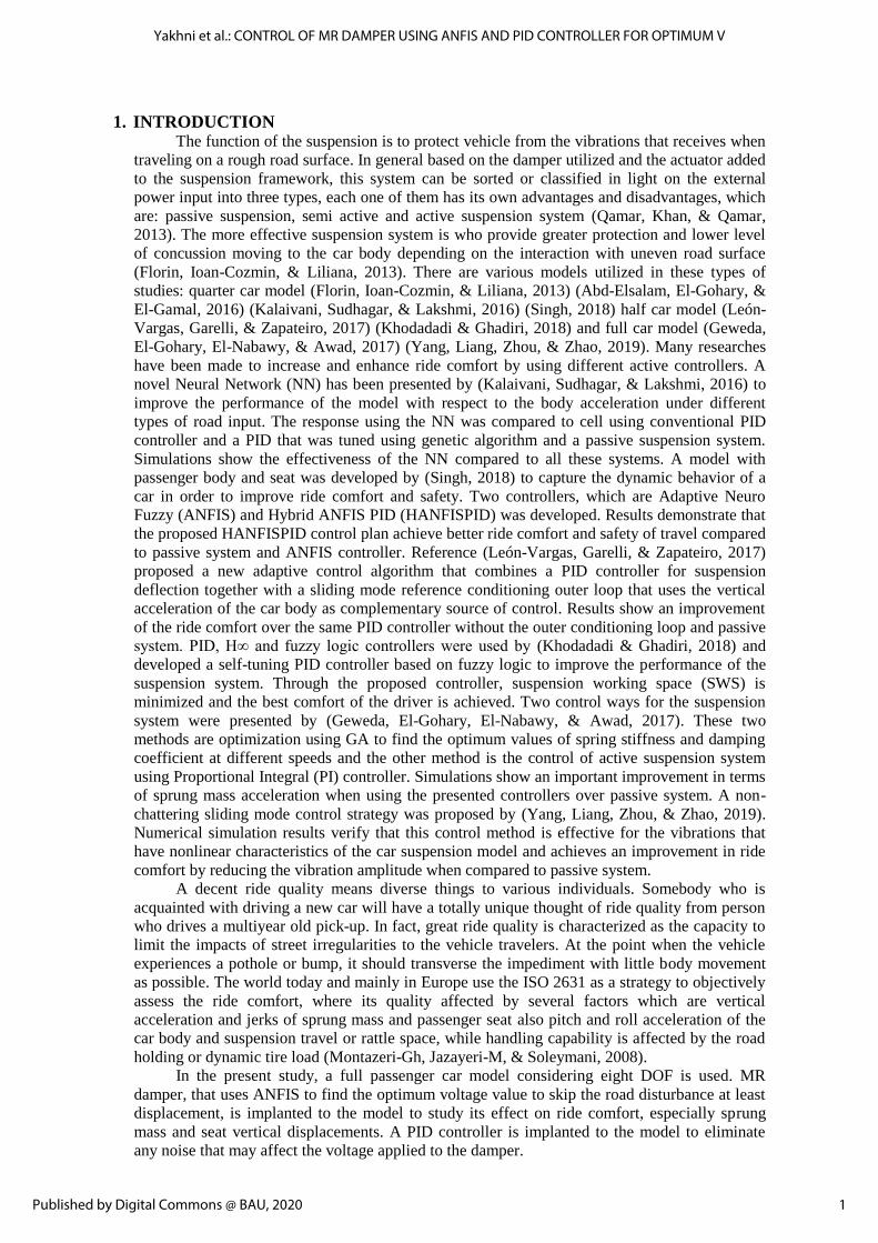
2.1. Full Car Model A full car model with the driver’s seat is considered to study in this research. Fig. 1
shows an eight DOF full vehicle model, it consists of driver seat, sprung mass which refers
to the part supported by springs, unsprung masses which refers to the front and rear wheels
assembly. The suspension between the passenger seat and the sprung mass, also the
suspension system between the sprung and unsprung masses are modeled as springs and
dampers with linear characteristics. The four tires are modeled as linear spring and its
damping coefficient is neglected because the damping characteristics of a tire is negligible
compared to tire stiffness as indicated by (GUCLU, 2003) (Shirahatti, Prasad, Panzade, &
Kulkarni, 2008) (Wang & Song, 2013). The sprung mass is considered to have three DOF
which refer to pitch, roll and bounce motion. The driver seat and the four unsprung masses
are modeled to have one DOF each in the vertical direction (GUCLU, 2003) (Montazeri-
Gh, Jazayeri-M, & Soleymani, 2008).
Fig.1: Eight DOF full vehicle model
Reference: (Shirahatti, Prasad, Panzade, & Kulkarni, 2008)
2.2. Mathematical Modeling The mathematical equations of the full car model with eight DOF and the MATLAB
SIMULINK model considered by (Shirahatti, Prasad, Panzade, & Kulkarni, 2008) is used in
this study. These equations were obtained using Newton’s second law of motion and free-
body diagram concept. The labels and parameters adopted in this model are that have been
used by (Shirahatti, Prasad, Panzade, & Kulkarni, 2008).
2.3. Magneto Rheological (MR) Damper
MR fluid can be used as one of the most important engineering application which is the
construction of damper. This device is called MR linear damper, it is controllable and smart
damper. These features can be achieved by applying voltage or current to the damper for
creating magnetic field that changes the yield strength of the MR fluid and therefore the
viscosity of the liquid. So the important asset of this damper is the controllability which can
be adjusted to achieve the desired amount of dissipating energy or damping level.
Obtaining the desired level of damping is achieved by applying a voltage or current to vary
the magnetic induction in an orifice that separate the two chambers of the MR fluid, so the
viscosity of the fluid that passes thorough this orifice changes, which affects the damping
coefficient of this damper.
2
BAU Journal - Science and Technology, Vol. 2, Iss. 1 [2020], Art. 10
https://digitalcommons.bau.edu.lb/stjournal/vol2/iss1/10
2.3.1. Magneto rheological fluids
There are a group of fluids which differ from other typical fluids, they have
special characteristics and called MR fluids. They are non-Newtonian rheological stable
with shear yield strength and are controlled by applied a magnetic field. This type of
fluids is consisting of small particles that have magnetic characteristics and dispersed in
a liquid, so the properties of this fluid can be changed or controlled by applying an
external magnetic field. The concentration of the magnetic particles, their shape and size
are parameters that determine the properties of the MR liquid in addition to the
temperature, the intensity of the magnetic field and the properties of fluid carriers. Some
materials that act as fluid bearers are water, mineral oil, silicon and glycerol. The
diameter of the magnetic particles is between 0.5µm and 8µm (Attia & N.M. Elsodany,
2017).
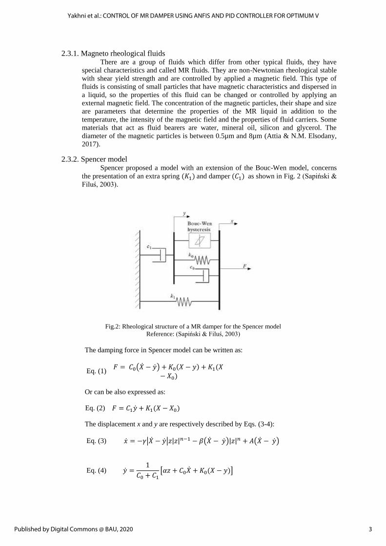
2.3.2. Spencer model Spencer proposed a model with an extension of the Bouc-Wen model, concerns
the presentation of an extra spring (𝐾1) and damper (𝐶1) as shown in Fig. 2 (Sapiński &
Filuś, 2003).
Fig.2: Rheological structure of a MR damper for the Spencer model
Reference: (Sapiński & Filuś, 2003)
The damping force in Spencer model can be written as:
Eq. (1) 𝐹 = 𝐶0(�̇� − �̇�) + 𝐾0(𝑋 − 𝑦) + 𝐾1(𝑋
− 𝑋0)
Or can be also expressed as:
Eq. (2) 𝐹 = 𝐶1�̇� + 𝐾1(𝑋 − 𝑋0)
The displacement x and y are respectively described by Eqs. (3-4):
Eq. (3) �̇� = −𝛾|�̇� − �̇�|𝑧|𝑧|𝑛−1 − 𝛽(�̇� − �̇�)|𝑧|𝑛 + 𝐴(�̇� − �̇�)
Eq. (4) �̇� =1
𝐶0 + 𝐶1[𝛼𝑧 + 𝐶0�̇� + 𝐾0(𝑋 − 𝑦)]
3
Yakhni et al.: CONTROL OF MR DAMPER USING ANFIS AND PID CONTROLLER FOR OPTIMUM V
Published by Digital Commons @ BAU, 2020

Where:
𝐶0 = 𝐶0𝑎 + 𝐶0𝑏𝑈 𝛼 = 𝛼𝑎 + 𝛼𝑏𝑈
𝐶1 = 𝐶1𝑎 + 𝐶1𝑏𝑈 �̇� = −𝜇(𝑈 − 𝑣)
𝐶1 Parameter that suits viscos damping at high speed.
𝐾1 Represents the stiffness at high speed.
𝛽, 𝛾, 𝐴 Parameters representing the control of the linearity during unloading and the
smoothness of transition from the pre-yield to post-yield area.
𝛼 Parameter representing the stiffness of the spring for damping force component
associated with the evolution variable z.
𝐾0 Parameter representing the stiffness of the spring associated with the nominal
damper due to accumulator.
𝐶0 Parameter representing viscous damping.
𝑋0 Parameter representing the initial displacement of the spring with the
stiffness K0.
The values of the above parameters of MR damper are taken as (Mahmoud El-Kafafy,
2012) and shown below:
Eq. (5) 𝑓1 = 𝐶1�̇� + 𝐾1(𝑍 − 𝑍1 − 𝑎𝜃
− 𝑤𝜑)
Eq. (6) 𝑓2 = 𝐶1�̇� + 𝐾1(𝑍 − 𝑍2 + 𝑏𝜃
− 𝑤𝜑)
Eq. (7) 𝑓3 = 𝐶1�̇� + 𝐾1(𝑍 − 𝑍3 − 𝑎𝜃
+ 𝑤𝜑)
Eq. (8) 𝑓4 = 𝐶1�̇� + 𝐾1(𝑍 − 𝑍4 + 𝑏𝜃
+ 𝑤𝜑)
Eq. (9) �̇� =
1
𝐶1 + 𝐶0[𝛼𝐽 + 𝐾0(𝑍 − 𝑎𝜃 − 𝑊𝜑 − 𝑦) + 𝐶0(�̇� − 𝑎�̇�
− 𝑊�̇�)]
Where: U is the voltage applied to the damper.
The values of parameters of MR damper are:
𝐴 = 58 𝐶0𝑏 = 1803 𝑁. 𝑠/𝑚 𝛼𝑏 = 38430 𝑁/𝑚
𝐶1𝑎 = 14649 𝑁. 𝑠/𝑚 𝐾0 = 3610 𝑁/𝑚 𝐵 = 2059020 /𝑚2
𝐶1𝑏 = 34622𝑁. 𝑠/𝑚 𝐾1 = 840 𝑁/𝑚 𝛾 = 136320 /𝑚2
𝐶0𝑎 = 784 𝑁. 𝑠/𝑚 𝛼𝑎 = 12441 𝑁/𝑚 𝜇 = 190 /𝑠
Eq. (10) 𝐽̇ = 𝐴(�̇� − 𝑎�̇� − 𝑊�̇� − �̇�) − 𝐵|𝐽|2(�̇� − 𝑎�̇� − 𝑊�̇� − �̇�)
− 𝛾|�̇� − 𝑎�̇� − 𝑊�̇� − �̇�||𝐽|𝐽
Eq. (11) 𝐶0 = 𝐶0𝑎 + 𝐶0𝑏𝑈
Eq. (12) 𝐶1 = 𝐶1𝑎 + 𝐶1𝑏𝑈
Eq. (13) 𝛼 = 𝛼𝑎 + 𝛼𝑏𝑈
Eq. (14) �̇� = −𝜇(𝑈 − 𝑣)
4
BAU Journal - Science and Technology, Vol. 2, Iss. 1 [2020], Art. 10
https://digitalcommons.bau.edu.lb/stjournal/vol2/iss1/10

3. SIMULATIONS AND CONTROL METHODS
3.1. Matlab Simulink Model The full vehicle model is created using Matlab/Simulink (R2014b Simulink 8.4) Fig. 3
shows the flow chart from the input (road profile and speed) to the car body and finally the
outputs (seat and sprung mass vertical displacements).
Fig.3: The Simulink model flow chart
3.2. Model Validation To check the correctness of this model a comparison has done between the response of
this model and that of (Shirahatti, Prasad, Panzade, & Kulkarni, 2008) in term of sprung mass
displacement (𝑍) with respect to time when the same inputs (road profile) ,shown in Fig. 4,
were applied to these two models.
Responses obtained are shown in Fig. 5. By comparing them, results show that the
response of the Simulink model is in agreement with that of the reference. So, the eight DOF
model created in this study matches (Shirahatti, Prasad, Panzade, & Kulkarni, 2008), this
means that it is valid and can be used to do all needed simulations.
Fig.4: Road profile used for model validation
Reference: (Shirahatti, Prasad, Panzade, & Kulkarni, 2008)
Speed
Road Profile
Full Car Model (With semi active
suspension system)
Seat displacement
Sprung mass displacement
5
Yakhni et al.: CONTROL OF MR DAMPER USING ANFIS AND PID CONTROLLER FOR OPTIMUM V
Published by Digital Commons @ BAU, 2020

Fig.5: Sprung mass vertical displacement vs. time for (a) Reference (Shirahatti, Prasad,
Panzade, & Kulkarni, 2008) and (b) the Simulink model.
3.3. Road Profile A speed hump is a raised area in the roadway pavement surface extending
transversely across the travel way. Speed humps are sometimes referred to as “pavement
undulations” or “sleeping policemen”. Common speed hump shapes are sinusoidal,
parabolic and circular. Most agencies implement speed humps with a travel length of 12 to
14 feet (3.7 to 4.3 m). Speed humps are generally used on residential local streets.
In this study a speed hump that has a half sine wave shape with 4 m wavelength. The
amplitude of this hump is changed from 0.01 m to 0.2 m to study the effect of these
different amplitudes on the vehicle. This hump is used as input to the car model and the
vehicle is moving with variable speeds from 20 to 120 km/h, in each change to the hump
amplitude, these speeds are adopted. The road hump shape is shown in Fig. 6 for 0.1 m (as
example of one case of all cases used in this study) amplitude and for different speeds. The
model is assumed to be constant and the hump is moving under it with variable speeds, so
the hump time changes from one speed to another. In the simulation stage the time response
is obtained. There is a time delay between the front and rear wheel inputs. The time delay is
shown in Eq. (15):
Eq. (15) 𝑡 =𝑎 + 𝑏
𝑣
Where: (𝑎 + 𝑏) is the distance between the front and rear axles and 𝑣 if the vehicle speed.
Fig.6: Road hump shapes for variable speeds
6
BAU Journal - Science and Technology, Vol. 2, Iss. 1 [2020], Art. 10
https://digitalcommons.bau.edu.lb/stjournal/vol2/iss1/10

3.4. Adaptive-Network-based Fuzzy Inference System (ANFIS) Modelling of a system dependent on regular numerical tools (e.g., differential
equations) isn't appropriate for managing badly characterized and questionable systems. By
contrast, a fuzzy inference system utilizing fuzzy if-then rules can demonstrate the qualitative
parts of human information and thinking forms without utilizing exact quantitative
examinations. This fuzzy modelling or fuzzy distinguishing proof, first investigated
methodically by Takagi and Sugeno, has discovered various practical applications in control
expectation and inference. However, there are some basic aspects of this approach which are
in need of better understanding (Jang, 1993).
3.5. Proportional Integral Derivative (PID) A PID controller is a nonexclusive control loop feedback mechanism broadly utilized
in industrial control frameworks. An "error" as distinction value between a deliberate
procedure variable and a desired set point is calculated by the controller. Then it attempts to
limit the error by altering the procedure control inputs. The PID parameters utilized in the
calculation must be tuned taking into consideration the nature of the system to achieve better
performance. The PID controller calculation includes three separate parameters: the
proportional, the integral and the derivative values, signified 𝐾𝑝,𝐾𝑖 and 𝐾𝑑.The response to
the current error is controlled by the estimation of the proportional parameter, while the
response dependent on the sum of recent errors is dictated by the integral term value and the
derivative controller anticipates the future behavior of the error. The control component
utilizes the weighted sum of these three actions to adjust the process of the framework. The
controller can provide control action intended to process necessities by tuning the parameters
of the PID controller. The reaction of the controller can be portrayed as far as the
responsiveness of the controller to an error, how much the controller overshoots the set point
and the level of the system oscillations (Geweda, El-Gohary, El-Nabawy, & Awad, 2017).
3.6. Control Strategy This section discusses the control method that has been adopted to achieve ride
comfort. As mentioned above, the desired goal is achieved by minimizing, as possible, the
impact of the vibrations that are transferred to the body of the vehicle and thus to the driver
and passengers, resulting from the uneven road surface.
The controller that has adopted in this research to perform this purpose is the MR
damper, whose characteristics and method of operation are explained above, and since the
properties of this damper is changed, in terms of its ability to absorb vibrations or chocks to
which it is exposed and dissipate energy, and that is through varying the voltage value
applied to the coils. So for each vibration received by this damper a certain voltage value
that achieves the best response. Since this damper is used in the car suspension system, the
driver is not able to determine the appropriate voltage value. First, he is driving on a
random road, second, it is unable to get off his car and check the surface of the road he will
pass. Also, using one value for the voltage in dealing with different types of road surface
will cause many problems. For example, instead of being a cause to reduce vibrations
transferred to the car body, it may increase them. So, each surface has to be treated with a
suitable voltage value. Therefore, in this study, a solution has been found, and if it is not
ideal for different road types, it performs a good function by reducing the vibrations
transmitted to the passengers.
MATLAB Simulink software is used to create eight DOF full car model with driver
seat, and then use the same model and implanted to it a MR damper, to finally have two
models, model without MR damper (only passive damper) and model with MR damper, it
should be noted that this model has four MR dampers located in the four corners of the
vehicle body and implanted between the sprung and unsprung masses. Thus, the response of
each model can be obtained and compared for the same input. After applying the road
profile, the comparison has been done between these two models with respect to the sprung
mass displacement, so the goal was to find the value of the voltage that achieved the least
displacement, in term of response peak (by trial and error method). Thus, after changing the
7
Yakhni et al.: CONTROL OF MR DAMPER USING ANFIS AND PID CONTROLLER FOR OPTIMUM V
Published by Digital Commons @ BAU, 2020

amplitude of the speed hump and the velocity of the vehicle and after doing all
comparisons, a set of voltage values have been obtained that suit each input and achieved
the best possible function. As discussed above, it is very difficult or rather impossible for
the driver, each time he passes on an uneven road surface, to get off his car and measure the
height of the surface and determine the speed that passes over it exactly, also, one voltage
value cannot be adopted in dealing with the different road surface, was form it is necessary
to find a solution for this problem. ANFIS was adopted as a solution in this study. When the
comparison was made, large number of data was obtained, includes the appropriate voltage
for each amplitude and velocity. These data have been used to train the ANFIS controller.
This control system has two inputs (speed and road profile) and one output (voltage)
as shown in Fig. 7.
Fig.7: ANFIS inputs and output
The figure below shows the loaded data into the ANFIS editor GUI.
Fig. 8: Loaded training data plot in the ANFIS editor
The acquired dynamic data is considered as a group training data for the ANFIS
controller. A FIS file is generated in the GUI having nine Gaussian membership functions
for each inputs and output. Finally, we train the FIS file with hydride optimization taking
zero tolerance error and 10 epochs. The training error comes out to be 0.04841. Fig. 9
shows the surface viewer of the ANFIS model.
Speed
Road
Profile
ANFIS
(Sugeno) Voltage
8
BAU Journal - Science and Technology, Vol. 2, Iss. 1 [2020], Art. 10
https://digitalcommons.bau.edu.lb/stjournal/vol2/iss1/10

Fig.9: ANFIS surface viewer
The Simulink full car model with MR damper and ANFIS controller is shown in Fig. 10.
Fig.10: Simulink model with MR damper based ANFIS voltage prediction
Since this study is based on providing ride comfort in the field of transportation, by
reducing vibrations transmitted to the vehicle body and then to the driver and passengers.
Therefore, taking into consideration any problem that may arise on the control system that
was established is necessary in order to achieve the goal of this research and increase the
effectiveness of the controller to achieve better performance. The system that was adopted
in this study is based on MR dampers, which effectiveness to absorbing vibrations and
shocks changes with respect to the voltage value applied to these dampers, in which, for
each road disturbance a voltage value that achieve the best performance of the vehicle when
overcoming this obstacle. The voltage prediction is done, as indicated above, by an
intelligent controller, and that by reading the vehicle speed and the road profile. But in the
event of any disruption to the voltage value sent to the dampers, whether it is an increase or
decrease in this value, this will reduce the effectiveness of the control system. Therefore,
this situation had to be taken into consideration, and find a solution to eliminate any
disturbance affecting the desired voltage value. The controller that was adopted to deal with
this case is the PID controller, which was implanted to the system as shown in the block
diagram below (Fig. 11). The PID controller calculates the error between the actual and the
desired voltage, and then attempts to minimize this error and cancelling any value of noise.
The noise was inserted to the model in the form of second order transfer function that has a
random value.
Speed
Full Car Model
(With MR damper) Road
Profile
ANFIS
Sprung mass
Vertical displacement
Seat Displacement
Voltage (V)
9
Yakhni et al.: CONTROL OF MR DAMPER USING ANFIS AND PID CONTROLLER FOR OPTIMUM V
Published by Digital Commons @ BAU, 2020

Fig.11: Simulink model with PID controller
4. RESULTS AND DISCUSSION
4.1. Without Noise The following figures (Fig. 12-15) show the response of the body and seat
displacements at 0.12 and 0.1 m amplitude for 120 and 60 Km/h speeds, without and with
MR damper.
Fig.12: Sprung mass vertical displacements at 0.12 m amplitude for 60 and 120 Km/h speeds
Fig.13: Sprung mass vertical displacements at 0.1 m amplitude for 60 and 120 Km/h speeds
ANFIS PID Noise
Speed
Road
Profile
Full car Model
(With MR
damper)
Sprung mass
vertical
displacement
Seat displacement
Desired voltage Actual voltage
- +
10
BAU Journal - Science and Technology, Vol. 2, Iss. 1 [2020], Art. 10
https://digitalcommons.bau.edu.lb/stjournal/vol2/iss1/10

Fig.14: Driver seat vertical displacements at 0.12 m amplitude for 60 and 120 Km/h speeds
Fig.15: Driver seat vertical displacements at 0.1m amplitude for 60 and 120 Km/h speeds
As shown in Fig. 12-15, by comparing the system with MR damper to that without
this damper in terms of response peak: For sprung mass vertical displacement, the
improvement is 58.72% at 120 Km/h while it is decreased to 40.71% at 60 Km/h in case
of 0.12 m amplitude when using the proposed controller. At 0.1 m amplitude the response
is improved by 58.26% at 120 Km/h and by 40.73% at 60 Km/h. For driver seat
displacement, at 120 Km/h and 0.12 m amplitude the improvement achieved is 59.67%
and at 60 Km/h this value decreased to be 24.95%. The response is improved by 59.2% in
case of 0.1 m amplitude and 120 Km/h speed while the value of improvements is
decreased to 25.37% at 60 Km/h with the same amplitude.
11
Yakhni et al.: CONTROL OF MR DAMPER USING ANFIS AND PID CONTROLLER FOR OPTIMUM V
Published by Digital Commons @ BAU, 2020

Fig.16: Sprung mass vertical displacements' peak for different speeds (a)
at 0.12 m amplitude and (b) at 0.1 m amplitude
Fig.17: Driver seat vertical displacements’ peak for different speeds (a)
at 0.12 m amplitude and (b) at 0.1 m amplitude.
The above diagrams show the variation of the response peak for the sprung mass
and seat displacement at different speeds. These diagrams show that the improvement of
the response, when using MR damper based ANFIS controller compared to passive
system is in its highest value (approximate 60%) at high speed while this value decreased
to be 0% approximately at low speed.
4.2. In Case of Noise Fig. 18 below shows the obtained voltage when the vehicle travels over a hump that
has a 0.1 m height and at 80 Km/h, in the normal case (in absence of disturbance), also it
shows the voltage when a noise affected it, with and without PID controller.
Fig. 18: Voltage variations in different cases
12
BAU Journal - Science and Technology, Vol. 2, Iss. 1 [2020], Art. 10
https://digitalcommons.bau.edu.lb/stjournal/vol2/iss1/10

As shown in the above figure, in case of PID, the voltage value varies to reach a
maximum value equal to 2.3 V, so it increase about 9.6% compared to the normal value
(2.08 V), while its value, in absence of the PID, varies to reach 3.18 V as peak value, which
is equal to 134.5 % of the normal value. This causes problems in the system, as mentioned
above, in the absence of PID controller.
Fig. 19 shows the response of the system (Driver Seat Displacement), for the same
case of Fig. 20 (Amplitude = 0.1 m and speed = 80 Km/h).
Fig.19: Driver seat displacements
The response of the system without MR damper and that when semi active
suspension system is used, in absence of noise, were discussed in the previous section.
Fig. 19 shows that when the voltage affected by noise and the PID was not implanted
to the system, the seat displacement ‘peak increase 7.73% compared to the response with
MR damper in absence of noise. But when PID controller was implanted to the model, the
response takes approximately the same path that of the seat displacement in the normal case
with MR damper.
5. CONCLUSIONS A. Providing ride comfort was the objective of this study, in order to achieve this goal, an eight
DOF full car model was developed using Matlab Simulink.
B. The model was assumed to travel on a speed hump has amplitude that varies from 0.01 to
0.2 m with different speeds from 20 to 120 Km/h.
C. MR damper was implanted to the model to study its effect on ride comfort.
D. ANFIS controller was used to find the optimum voltage value applied to the damper.
E. Results show that the MR damper improves the vehicle ride comfort over the passive
suspension system.
F. The improvement is in the form of, approximately, 60% reduction in the response peak of
seat and sprung mass vertical displacements at 120 km/h speed, while its level gradually
reduced with low speed.
G. The PID controller plays an important role by cancelling the effect of noise that affects the
voltage sending to the MR damper.
REFERENCES
Abd-Elsalam, A., El-Gohary, M. A., & El-Gamal, H. A. (2016). Simulation of Nonlinear
Quarter Car Suspension System with and without Tire Damping. International Journal of
Advanced Scientific and Technical Research, 98-105.
Attia, E., & N.M. Elsodany, H. E.-G. (2017). Theoretical and experimental study of magneto-
rheological fluid disc brake. Alexandria Engineering Journal, 56, 189-200.
13
Yakhni et al.: CONTROL OF MR DAMPER USING ANFIS AND PID CONTROLLER FOR OPTIMUM V
Published by Digital Commons @ BAU, 2020

Florin, A., Ioan-Cozmin, M.-R., & Liliana, P. (2013). Pasive suspension modeling using
matlab, quarter car model, imput signal step type. TEHNOMUS - New Technologies and
Products in Machine Manufacturing Technologies, 258-263.
Geweda, A., El-Gohary, M., El-Nabawy, A., & Awad, T. (2017). Improvement of vehicle ride
comfort using genetic algorithm optimization and PI controller. Alexandria Engineering
Journal, 56(4), 405-414.
GUCLU, R. (2003). Active Control of Seat Vibrations of a Vehicle Model Using Various
Suspension Alternatives. Turkish Journal of Engineering Enviroment and Science, 27, 361-
373.
Jang, J.-S. R. (1993, June). ANFIS Adaptive-Network-based Fuzzy Inference System. IEEE
Transactions on Systems Man and Cybernetics.
Kalaivani, R., Sudhagar, K., & Lakshmi, P. (2016). Neural Network based Vibration Control
for Vehicle. Indian Journal of Science and Technology, 9, 1-8.
Khodadadi, H., & Ghadiri, H. (2018, March). Self-tuning PID controller design using fuzzy
logic for half car active suspension system. International Journal of Dynamics and Control,
6(1), 224-232.
León-Vargas, F., Garelli, F., & Zapateiro, M. (2017, December 11). Limiting vertical
acceleration for ride comfort in active suspension systems. Journal of Systems and Control
Engineering, 223-232.
Mahmoud El-Kafafy, S. M.-D.-A. (2012). Automotive Ride Comfort Control Using MR Fluid
Damper. Engineering, 4(4), 179-187.
Montazeri-Gh, M., Jazayeri-M, S. Y., & Soleymani, M. (2008, October). Vehicle ride
evaluation based on a time-domain variable speed driving pattern. International Journal of
Vehicle Design, 47(1-4), 81-101.
Qamar, S., Khan, L., & Qamar, Z. (2013). Online Adaptive Full Car Active Suspension
Control Using B-Spline Fuzzy-Neural Network. 2013 11th International Conference on
Frontiers of Information Technology, Islamabad, 205-210.
Sapiński, B., & Filuś, J. (2003). Analysis of Parametric Models of MR Linear Damper. Journal
of Theoretical and Applied Mechanics, 41(2), 215-240.
Shirahatti, A., Prasad, P. S., Panzade, P., & Kulkarni, M. (2008, March). Optimal Design of
Passenger Car Suspension for Ride and Road Holding. Journal of the Brazilian Society of
Mechanical Sciences and Engineering, 30(1), 66-76.
Singh, D. (2018, May). Passenger Body Vibration Control in Active Quarter Car Model using
Hybrid ANFIS PID Controller. I.J. Intelligent Systems and Applications, 10(5), 51-60.
Wang, J., & Song, C. (2013). Computer Simulation on Fuzzy Control of Semi-active
Suspension System Based on the Whole Vehicle. International Journal of Multimedia and
Ubiquitous Engineering, 8(6), 217-228.
Yang, Z., Liang, S., Zhou, Y., & Zhao, D. (2019). Sliding Mode Control for Vibration Comfort
Improvement of a 7-DOF Nonlinear Active Vehicle Suspension Model. Journal of Robotics
and Mechatronics, 31(1), 95-103.
14
BAU Journal - Science and Technology, Vol. 2, Iss. 1 [2020], Art. 10
https://digitalcommons.bau.edu.lb/stjournal/vol2/iss1/10

APPENDIX Table 1: Nomenclature and parameters used in the full car model
Reference: (Shirahatti, Prasad, Panzade, & Kulkarni, 2008)
Parameter Description Value Unit
𝑴𝒑 Passenger seat mass 100 Kg
𝑴 Sprung mass 2160 Kg
𝑴𝟏 Front left side un-sprung mass 85 Kg
𝑴𝟐 Rear left side un-sprung mass 60 Kg
𝑴𝟑 Front right side un-sprung mass 85 Kg
𝑴𝟒 Rear right side un-sprung mass 60 Kg
𝑲𝒑 Passenger seat stiffness 98935 (N/m)
𝑲𝟏 Front left side suspension spring stiffness 96861 (N/m)
𝑲𝟐 Rear left side suspension spring stiffness 52310 (N/m)
𝑲𝟑 Front right side suspension spring stiffness 96861 (N/m)
𝑲𝟒 Rear right side suspension spring stiffness 52310 (N/m)
𝑲𝒕 Tire stiffness 200000 (N/m)
𝑪𝒑 Passenger seat damping coefficient 615 (Ns/m)
𝑪𝟏 Front left side suspension damping coefficient 2460 (Ns/m)
𝑪𝟐 Rear left side suspension damping coefficient 2281 (Ns/m)
𝑪𝟑 Front right side suspension damping coefficient 2460 (Ns/m)
𝑪𝟒 Rear right side suspension damping coefficient 2281 (Ns/m)
𝒂 Center of gravity (CG) location from front axle 1.524 (m)
𝒃 Center of gravity (CG) location from rear axle 1.156 (m)
𝟐 𝑾 Wheel track 1.45 (m)
𝑿𝒑 Distance of seat position from CG of sprung mass 0.234 (m)
𝒀𝒑 Distance of seat position from CG of sprung mass 0.375 (m)
𝑰𝒙 Mass moment of inertia for pitch 946 (kg- m2)
𝑰𝒚 Mass moment of inertia for roll 4140 (kg- m2)
𝑸𝟏 Road input at front left side
𝑸𝟐 Road input at rear left side
𝑸𝟑 Road input at front right side
𝑸𝟒 Road input at rear left side
15
Yakhni et al.: CONTROL OF MR DAMPER USING ANFIS AND PID CONTROLLER FOR OPTIMUM V
Published by Digital Commons @ BAU, 2020