Embed Size (px)
Citation preview

50 Transactions on Machine Design Volume 5 Number 2 August 2017
Control of the permanent magnet synchronous generator using sliding modes forwind turbine application
ABSTRACT: One of the most used generators applied in medium capacity wind system is the permeant magnet synchronousgenerator, because of its high efficiency. The wind speed is constantly changing and the control system can be controlling thegenerator´s speed by currents to maximize the wind energy. In order to optimize the operation of the wind system, a robustcontrol using Super-Twisting algorithm is applied, with which the generated power will be delivered to the grid electricityefficiently. We propose a decentralized controller in cascade form where the first stage the speed is controlled and the secondstage the grid-side inverter controller side to regulate the bus DC-voltage and connect the wind system with the utility grid.A dynamic model of the permanent magnet synchronous generator at dq coordinate frame is used in the process design of thespeed controller. A LCL-filter is used as coupling medium between the wind system and the grid. Finally, simulation results ofthe wind systems are reported to validate the performance of the proposed controller.
Keywords: Permanent magnet synchronous generator, Super-twisting algorithm, Grid-side inverter
Received: 23 April 2017, Received 21 May 2017, Accepted 28 May 2017
© 2017 DLINE. All Rights Reserved
1. Introduction
The energy situation of the world is critical: the hydrocarbons tend to deplete, as well as the pollution that these cause.Research and development of systems that depend on clean energies such as solar and wind power is of paramount importance.
The permeant magnet synchronous generator (PMSG) is a rotary electric machine capable of transforming mechanical energy,in this case the wind energy, into electricity; magnets that are mounted in the rotor provide the magnetizing of the generator [1].
Daniel Gerardo Ortega MezaAutonomous University of cd. Juarez. [email protected] Amador Morfin Garduño, Manuel Ivan Castellanos GarciaAutonomous University of cd. Juarez. [email protected], [email protected]
Transactions on Machine Design Volume 5 Number 2 August 2017 51
Contribution: This work proposes a robust control scheme based on the block control linearization (BC) technique combinedwith a second-order sliding mode control, called the Super-Twistig (ST) algorithm. The BC technique is used to design a variabletracking error surface, whereas the ST algorithm guarantees a robust convergence of the movement of the closed system stateto the surface.
The description of the procedure is to create a program in MathWorks® MATLAB® Simulink® which will simulate the behaviorof the whole control system of a wind turbine, creating as a first step a program that simulates the behavior of the wind turbine,which describes the dynamics of the turbine. Then the second step from the model of the CD motor create a control from theirequations of state where the torque is controlled, once the controller obtained the reference speed at which the DC motor hasto follow the torque of the emulator turbine created in the first step. The third step to create a control for the PMSG from the inputspeed of the generator, the controller is designed from its state equations obtaining the control surfaces to apply the controlalgorithm to the surfaces. The fourth step, it is necessary to deliver the energy extracted from the wind to the electric grid, for thisit is necessary the inverter model side electric grid, creating a controller from its state equations, this in order to find the controlsurfaces at the which the control algorithm will be applied.
2. Description of the control system
In wind applications where the PMSG is used, the typical connection scheme is shown in Figure 1., where two inverters in back-to-back configuration, the inverter that is connected to the PMSG AC / DC allows controlling the speed of it and the inverter gridside DC / AC controls the power delivered to the electric grid.
The great advantage of this system is that compared to the conventional PMSG this does not require an excitation winding, alsoits high efficiency [1].
Figure 1. Diagram a blocks of a system Back to Back
3. Emulation of the wind turbine
It is proposed using a DC motor controlling the torque, proposing a reference torque, in this case that of the turbine emulator,using the following equations.
The wind turbine is a turbomachine motor that exchanges movement with the wind, by rotating a rotor. The mechanical energyof the rotor shaft can be harnessed to generate electricity, the energy extracted from the wind can be described as followsequations [2, 3]:
2 312m t p wP R C vρπ= (1)
where Pm is the mechanical power extracted from the wind, ρa is the air density, vw is the wind speed, Rt the turbine radius, ansCp is the power coefficient, which can be modelled of the following form [2, 3] :

52 Transactions on Machine Design Volume 5 Number 2 August 2017
( )5
1 1 4 61, ,i
C
p vi
C C C C e Cλλ β β λλ
−⎛ ⎞= − − +⎜ ⎟
⎝ ⎠(2)
the term λv named as velocity tip ratio is defined as follows [2, 3]:
, tb tv
w
Rv
ωλ = (3)
ωtb is the velocity turbine [2, 3]:
( )3
1 1 0.035 , 0.08 1iλ λ β β= −
+ + (4)
where β is the angle attack of the wings, each wind turbine has very particular characteristics, the equations shown are the mostgeneral way of representing them.
4. Dynamic model of the cd motor for the emulator
The DC motor is a machine that has a simple dynamics, But which in turn presents diverse equations because the motor performselectrical and mechanical phenomena shown in eq. (5) [4, 5, 6].
,mm m ea m
m m
eff
m
Kd B Ti
idt J J Jω
ω= − −
1 ,f ea aa m a
a a a
ffKdi Ri u
dt L L Li
ω= − − + (5)
Armature resistance Ra, armature inductance La, ωm is defined as the angular velocity, ia is the armature current, ieff is the effectivecurrent, Km is the motor constant mechanical, Kf is the motor constant electric, Te is the electromagnet torque,Jm moment ofinertia, Bm coefficient of friction and ua is the supply voltage and the control input. For the purpose of emulation of the turbine,the technique is used by feedback of states, where we define the error variables as follows:
20.0000351eref tbT ω= (6)
,ref ecd T Tε = − (7)
,refcd f eff aT K i iε = −
εcd = Tref - Kfieffia = - Kmεcd, (8)
where Tref is the reference torque, to apply the ST control algorithm it is necessary to define the control surface:
Scd = Kmεcd - εcd, (9)
where km > 0. In such a way it is like emulating the turbine, for the control of speed we apply the control algorithm ST [4, 5]:
. . .
.

Transactions on Machine Design Volume 5 Number 2 August 2017 53
(1/ 2)1| | ( )a cd cdu s sign s uλ= +
( )1
, , ,
a
cd a
u u uu
sign s u uα⎧ >⎪= ⎨ ≤⎪⎩
&(10)
where u is the nominal value of the motor armature DC. The gains of control λ and α So that the state vector of the systemconverges to the surface s = 0 in finite time, s are errors. The measured state variables are the torque of the rotor, Te and thecurrent ia. This way the emulation of the turbine is made.
5. Dynamic model of Synchronous machine
The model of the synchronous machine is the same as for generator and motor. The conditions are different for the generator asgenerating currents are negative and as motor are positive; the model is defined from the following [5, 6]:
v r i ,aa a a
ddxψ
= +
v r i ,bb b b
ddxψ
= + (11)
v r i .cc c c
ddxψ
= +
The model of PMSG is of order three, working with the previous model is complex, reason why it is used to the transformationof Park eq.(12) Which changes the frame of reference of an abc model to a model dq0 orthogonal coordinate frame, which allowsto reduce the order of the equations, if the model is balanced the zero reference is equal to zero. The signals obtained are similarto direct signals [4]:
( )
( )
2 2 3 3
2 2 2 ,3 3 3
2 2 22 2 2
dq
cos cos cos
T sin sin sin
π πδ δ δ
π πδ δ δ
⎡ ⎤⎛ ⎞ ⎛ ⎞− +⎜ ⎟ ⎜ ⎟⎢ ⎥⎝ ⎠ ⎝ ⎠⎢ ⎥⎢ ⎥⎛ ⎞ ⎛ ⎞= − − − − +⎢ ⎥⎜ ⎟ ⎜ ⎟
⎝ ⎠ ⎝ ⎠⎢ ⎥⎢ ⎥⎢ ⎥⎣ ⎦
(12)
the simplified dynamic model in the dq orthogonal coordinate frame is more efficient and simple [1, 5, 7, 8]:
qd e dd e q
d d d
Ldi R ui pi
dt L L Lω= − + +
.q f qe dq e d e
q q q q
di uR Li pi p
dt L L L Lψ
ω ω= − − − + (13)
Re is the stator resistance, Lq and Ld are the inductances of the generator d y q. ψf is the permanent magnet flux and ωe is the

54 Transactions on Machine Design Volume 5 Number 2 August 2017
speed of electric rotation of the generator, p is the number of poles of the generator. The electric speed is defined as [1, 5]:
dδ/dt = ωe, (14)
The mechanical speed is a function of the number of poles p of the generator [1, 5]:
ωm = ωep. (15)
In the mechanical subsystem, the torque generated internally by the rotor balances the opposition pairs as the friction pair, theinertial torque and the load torque. Using Newton’s second law we obtain the differential equations that describe the mechanicalbehavior of the generator [1, 5, 9]:
,g mm e l
g g g
Bd T Tdt J J J
ωω= + − (16)
where they are defined as follows ωm is the mechanical speed, Tl is the charging pair, Jg is the equivalent of the moment of inertia,Bg is the coefficient of viscous friction, the electromagnetic torque Te is defined as follows:
,m
eT Pω
= 17)
where de P is the power, E is the voltage of the generator then [1, 7, 9]:
3 ,2e q fT pi ψ= (18)
the state equations eq.(13) are fundamental for defining control surfaces.
6. PMSG speed control
Figure 2. PMSG control schemes
The Park transformation of the dynamic generator model allows designing a controller from the dq orthogonal coordinate frame.The complete scheme is shown in Figure 2., where we can observe how the sensed data are obtained and what is the order of thecontrol.
Starting from the following [1]:

Transactions on Machine Design Volume 5 Number 2 August 2017 55
1 ,re mfε ω ω= − (19)
where ωref is the reference speed at which we want the PMSG to remain stable, ω m is the mechanical speed that is entering to thePMSG.
ε1 = ωref - 1/J (Te + Tl - Bg ωm), (20)
we also substitute Te:
ε1 = ωref + Tl/J -Bωm/J - 1/J 3/2 piqψf , (21)
considering that it is cylindrical poles as follows:
ε1 = ωref + 1/J (Tl - Bωm - 3p/2 iqψf) = -K1ε1, (22)
the constant K1 > 0. To apply the BC technique by currents of equation depending of iqref
iqref = 2/3pψf (Jg K1ε1 + Jg ωref - T1 + Bgωm), (23)
defined the reference current iqref, The control surface can be defined by comparing it against the current produced by PMSG atthat moment:
ε2 = iqref - iq, (24)
where:
ε2 = Sq, (25)
to define the surface for the reference current reference id axe is generated by PMSG and for the system to be the most stable andwith an adequate power factor we consider the idref = 0, then:
ε3 = idref - id, (26)
where:
ε3 = Sd, (27)
it is possible to apply the robust control algorithm [4]:
Sdq = [Sq Sd]T, (28)
udq = λ1 | Sdq |1/2 sign(Sdq) + u1c,
(29)
where Vcd = [vcd vcd]T is the voltage that controls Optimum of the PMSG, the dq axes is similar to direct signals. The gains ofcontrol λ1 and α1 ensures that control surfaces achieve their control goal faster or slower as required, The surface s tend to zeroin finite time [4]. The measured state variables are the iq,ωme and id. Figure 2.
7. Dynamic model of grid-side converter
. .
. .
Vcd, |udq| > Vcdu1c ={α1 sign(Sdq), |udq|≤Vcd
.
. .
.
56 Transactions on Machine Design Volume 5 Number 2 August 2017
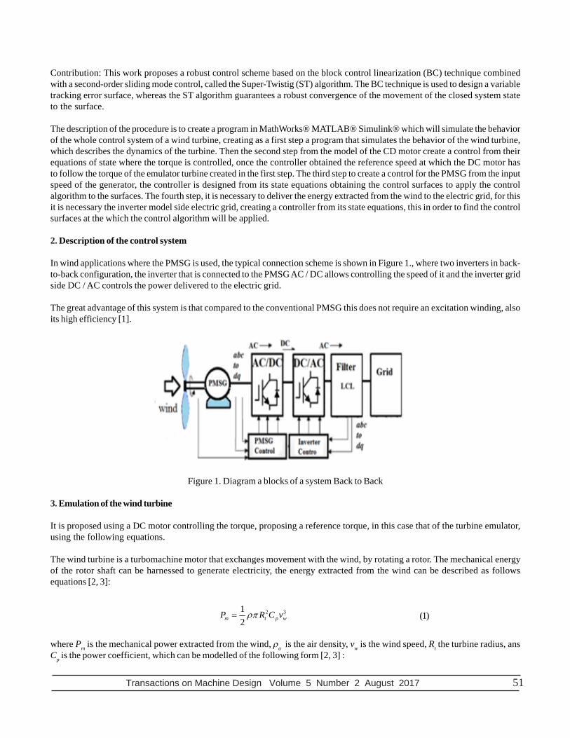
The Control system of the converter DC/AC delivery and synchronize the electricity generated by the PMSG to the electricitygrid, the system is built by a three-phase inverter, three coupling coils, power grid and controller. This system is designedaccording to the balance of voltages at coil terminals that match the electrical energy between the input and the output of theinverter as can be observed [4, 10]:
vabct - vabcs = Rc iabct + Lc diabct/dt,
vdc Cb = vTabctiabct, (30)
where vabct are the voltages of the electrical grid side, iabct are the currents of the electrical grid side, vabcs and iabcs are the voltagesand currents of the system. Rc and Lc is the resistance and inductance of the filter, Cb is the direct bus capacitor, vdc is the voltageof the capacitor on the direct bus. The system described is a fourth order system, to reduce the order we use Park eq.(12), whichfrom an abc model we convert it to a model in dq, in the following way [4, 10]:
(31)
where vds, vqs and ids, iqs are the voltages and currents of the system in the dq axes and vdt, vqt and idt, iqt Are the voltages andcurrents of the electrical grid side. For the design of the controller, the direct bus voltage is considered as the target to becontrolled. The following was developed in [4]:
ε1c = vdcref - vdc, (32)
derive the ε1c To get their system dynamics [4]:
ε1c = vdcref - vdc
ε1c = vdcref - 3/2Cbvdc (vdt idt - vqt iqt) = K1cε1c , (33)
the constant k1c > 0. Whit this information idt to obtain the reference current idtref. It is considered vqt Like zero, the definition isas follows [4]:
ε2c = idref - idt, (34)
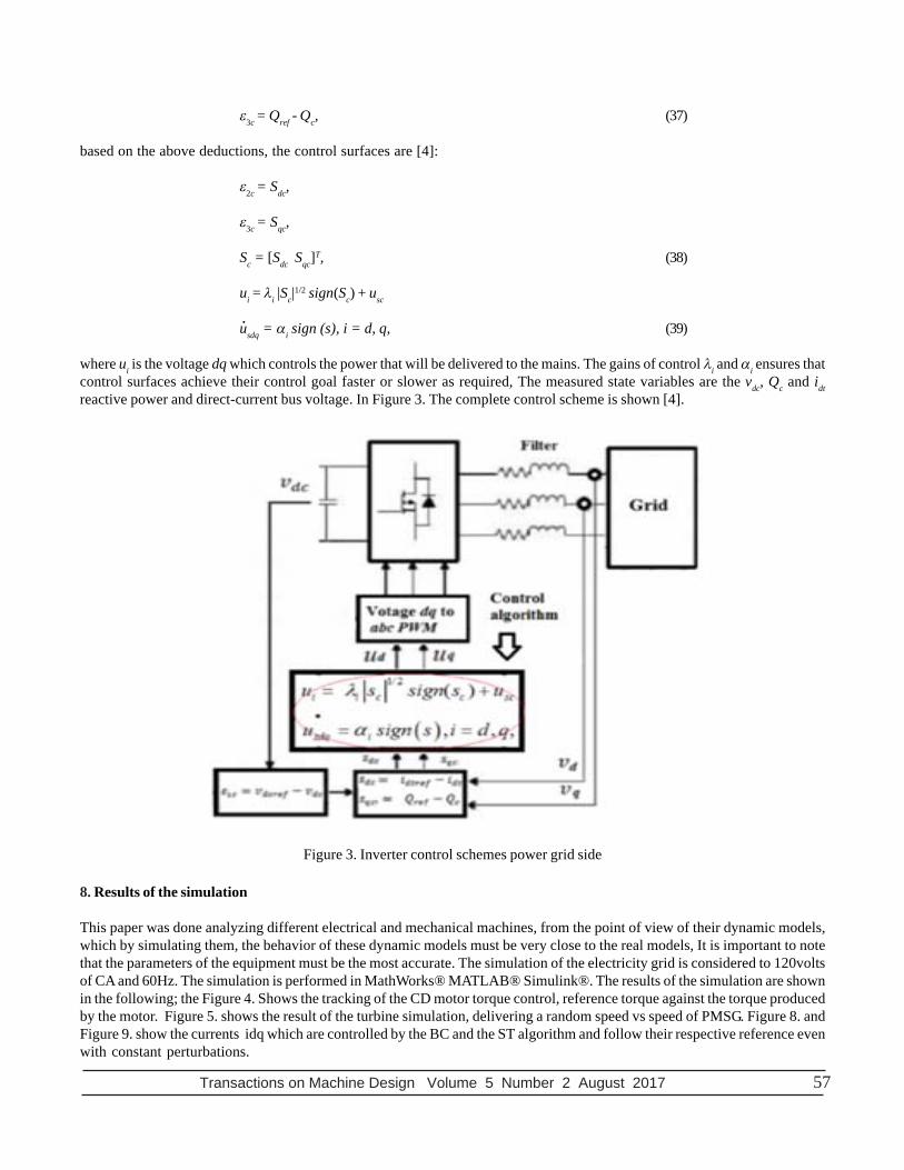
where P is the power of the system (W), the Qref (VAR), consider a power factor fp suitable so that there are no voltage drops,increase in current for that reason relates the following [4]:
(35)
the following error variable is defined [4]:
21 desref
des
fpQ P
fp−
= (36)
.
( )3 ,2
dcdt dt qt qt
b dc
dvv i v i
dt C v= −
,dt c dt dsdt t qt
c c
di R v vi idt Lc L L
ω= − + + −
,qt qt qscqt t dt
c c
di v vRi i
dt Lc L Lω= − − + −
1 12 ,3
b dc dc dcdtref
d t
C v Kiv
ε=
. . .
. .
Transactions on Machine Design Volume 5 Number 2 August 2017 57
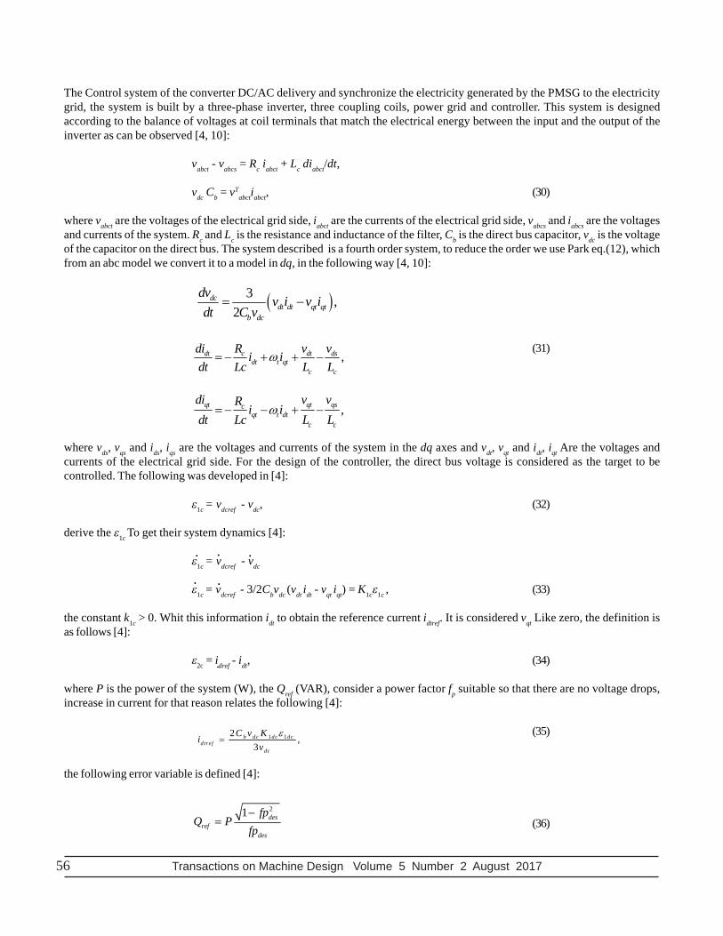
ε3c = Qref - Qc, (37)
based on the above deductions, the control surfaces are [4]:
ε2c = Sdc,
ε3c = Sqc,
Sc = [Sdc Sqc]T, (38)
ui = λi |Sc|1/2 sign(Sc) + usc
usdq = αi sign (s), i = d, q, (39)
where ui is the voltage dq which controls the power that will be delivered to the mains. The gains of control λi and αi ensures thatcontrol surfaces achieve their control goal faster or slower as required, The measured state variables are the vdc, Qc and idtreactive power and direct-current bus voltage. In Figure 3. The complete control scheme is shown [4].
.
8. Results of the simulation
This paper was done analyzing different electrical and mechanical machines, from the point of view of their dynamic models,which by simulating them, the behavior of these dynamic models must be very close to the real models, It is important to notethat the parameters of the equipment must be the most accurate. The simulation of the electricity grid is considered to 120voltsof CA and 60Hz. The simulation is performed in MathWorks® MATLAB® Simulink®. The results of the simulation are shownin the following; the Figure 4. Shows the tracking of the CD motor torque control, reference torque against the torque producedby the motor. Figure 5. shows the result of the turbine simulation, delivering a random speed vs speed of PMSG. Figure 8. andFigure 9. show the currents idq which are controlled by the BC and the ST algorithm and follow their respective reference evenwith constant perturbations.
Figure 3. Inverter control schemes power grid side
.

58 Transactions on Machine Design Volume 5 Number 2 August 2017
In the Figure 6. is the controlled delivered reactive power to the mains which is keep it regulated to zero. The Figure 7. is idcurrent delivered to the power grid brought to zero by the control. In Table 1. show the parameters used of simulation.
Parameter PMSG
Parameter Value unit
Re Stator resistance 4.765 Ω
p Generator poles 4
ψf Magnetization flow 0.1848 Wb
Ld Inductance in the d-axis 0.014 H
Lq Inductance in the 1-axis 0.014 H
Bg Coefficient of friction 0.0002 Nm/rad/s
Jg Inertia Equivalent 0.0001584 Kgm2
Parameter GRID-SIDE CONVERTER
Parameter Value unit
Rc Cable resistance 0.36 Ω
ωt Mains frequency 377 Rad/s
Cb Direct bus capacitor 2128 μF
C Filter capacitor 5 μF
Lc Filter Inductance 3.1 mH
Parameter cd motor ¾ Hp
Parameter Value unit
Ra Armature resistance 2.18 Ω
Bm Coefficient of friction 0.002 Nm/rad/s
Km Motor constant 0.1848
Jm Moment of inertia 0.0041 Kgm2
La Field Inductance 23.1 mH
Parameter turbine 300watts
Parameter Value unit
Rt Turbine Radius 1 m
ρa is the density of the air 1.225 Kg/m^3
J0 Moment of inertia 0.3 Kgm2
B0 Coefficient of friction 0.024 Nm/rad/s
Cp Constant of maximum power 0.2634
Table 1. Parameters

Transactions on Machine Design Volume 5 Number 2 August 2017 59
Figure 4. Tracking CD motor torque
Figure 5. Speed of the turbine to PMSG vs Speed reference
Figure 6. Current delivered to the grid id

60 Transactions on Machine Design Volume 5 Number 2 August 2017
Figure 7. Reactive power delivered to the grid
Figure 8. Current iq
Figure 9. Current PMSG id
Transactions on Machine Design Volume 5 Number 2 August 2017 61
9. Conclusion
It simulates a complete wind turbine, PMSG, inverter and mains. It was demonstrated that the ST control has the capacity tomaintain stable the power delivered to grid. Simulation in MathWorks® MATLAB® Simulink®. Dynamic models are a basic partbecause this is designed BC controllers. This paper is part of a series of research that, when implemented, has the capacity tooptimize the extraction of renewable energies.
Future work is to implement the control designed in this article directly in a dSPACE, using three inverters, one for the CD motorand the following for the control of the PMSG and inverter side electric grid.
References
[1] Tahri, A., Hassaine, S., Moreau, S. A robust control for permanent magnet synchronous generator associated with variablespeed wind turbine. Journal of Electrical Engineering, www.jee.ro.
[2] Rahelo, B., Hofmann, W., Gluck, M. (2004). Emulation of the Static and Dynamic Behaviour of a Wind-turbine with a DC-Machine drive, In: 35th Annual IEEE Power Electronics Specialists, Aackn, Germany.
[3] Kouadria, S., Belfedhal, S., Berkouk, E., Meslem, Y. (2013). Development of real time wind turbine emulator based on dc motorcontrolled by pi regulator, In: Eighth International Conference and exhibition on ecological vehicles and renewables energies,
[4] Morfin, O. A., Ruiz-Cruz, R., Loukianov, A. G., Saìnchez, E. N., Castellanos, M. I., Valenzuela, F. A. (2014). Torque controllerof a doubly-fed induction generator impelled by a DC motor for wind system applications, Published in IET Renewable PowerGeneration, p. 484 - 497, 14 July
[5] Utkin, V., Guldner, J., Shi, J. (2009). Sliding Mode Control in Electro-Mechanical Systems, Second Edition, CRC Press.
[6] Sen, P.E.(1996). Principles of electric machines and power electronics., Kingston, Ontario, Canada.
[7] Rajaei, A., Mohamadian, M., Varjani, A. Y. (2013). Vienna-Rectifier-Based Direct Torque Control of PMSG for Wind EnergyApplication, IEEE Transactions on Industrial Electronics, 60. 2919-2029, p. 7, July.
[8] Hieu Phan, D., Huang, S. (2015). Super-Twisting Sliding Mode Control Design for Cascaded Control System of PMSG WindTurbine, Journal of Power Electronics, 15 (5) 1358-1366, September.
[9] Babji Kumar, I. S., Bindu, S. (2016). “Direct control technique for PMSG based Variable speed Wind Applications, In:International Conference on Electrical, Electronics, and Optimization Techniques (ICEEOT), Manipal, India
[10] López Mesa, D. J., Camacho Muñoz , G. A., Díaz Chávez, J. O., Gaviria López, (C. A). (2009). Modulación pwm aplicada ainversores trifásicos dentro del esquema de accionamientos eléctricos AC, Ingeniería e Investigación, 29 (1).