Embed Size (px)
Citation preview
Introduction
Flow instabilities occur in a variety of commercialpolymer processing operations including extrusion, filmblowing, fiber spinning and coating. During the extru-
sion of molten polymer through capillary or slit diegeometries, a transition from a smooth surface to anearly periodic ridge-like surface distortion has beenobserved at a critical shear rate or wall shear stress(Petrie and Denn 1976; Denn 2001). These surface
Erik Miller
Jonathan P. RothsteinControl of the sharkskin instability in theextrusion of polymer melts using inducedtemperature gradients
Received: 11 February 2004Accepted: 21 May 2004Published online: 28 July 2004� Springer-Verlag 2004
Abstract The extrusion of polymermelts is often rate limited by theonset of an elastic surface instabilityknown as sharkskin. Appearance ofthese surface distortions is generallyunacceptable for commercial appli-cations. The desire to forestall theonset of sharkskin to higher outputrates has motivated a considerableamount of research to characterizethe nature of the instability. In thismanuscript, we will present a seriesof detailed experiments using a cus-tom fabricated extruder and die. Byincorporating thermal breaks andprecise localized temperature controlof the die and barrel, predeterminedtemperature gradients could be in-duced across the extrudate. Poly-mers are typically very poor thermalconductors, and therefore the effectsof heating or cooling from aboundary can be designed to onlyaffect the properties of the extrudatevery close to the die wall. We willpresent data correlating the ampli-tude and frequency of the sharkskininstability to the bulk and die sur-face temperature as well as the shearrates. The result is a quantitative
processing map that characterizesthe instability and demonstrates thatby modifying the rheology of thepolymeric fluid very near the die exitcorner, it is possible to suppress orcontrol the sharkskin instabilitythrough isolated die heating orcooling. By reformulating our datainto Weissenberg and Deborahnumbers using the relaxation timeevaluated at the wall temperature,we demonstrate that the sharkskinsurface instability is dependent onlyon flow kinematics and viscometricproperties of the fluid very near thedie wall, a result of the stress singu-larity present at the die exit, andindependent of bulk fluid properties.This technique could conceivablyincrease the profitability of extrusionprocesses and be extended to devel-op precisely-controlled sharkskin fordesigning specific functionality intoextruded surfaces.
Keywords Polyethylene extrusion ÆSharkskin Æ Surface instability ÆQuantitative characterization
Rheol Acta (2004) 44: 160–173DOI 10.1007/s00397-004-0393-4 ORIGINAL CONTRIBUTION
E. Miller Æ J. P. Rothstein (&)Department of Mechanical Engineering,University of Massachusetts, Amherst,MA 01003-2210, USAE-mail: [email protected]
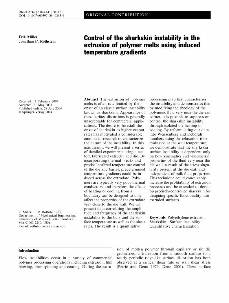
distortions are known as sharkskin. Flow instabilitiesduring extrusion were first observed after World War II,and early reports of sharkskin, in particular, date backto the 1960s (Howells and Benbow 1962; Tordella 1963).Detailed experimental observations on flow instabilitiesthrough 1975 are reviewed in a broad sense by Petrie andDenn (1976), and subsequently by Larson (1992). Amore specific review of flow instabilities, with a focus onsharkskin and its mechanism was written by Denn(2001). In general, and as detailed in the aforementionedreviews, distortions seen during extrusion have a pro-gression in severity. As shear rate or stress increases, theextrudate surface undergoes a transition from stable, tosharkskin, to stick-slip, and finally to gross melt frac-ture. In Fig. 1, a series of photographs are shown toillustrate the transition from smooth, to loss of gloss, tofully developed sharkskin.
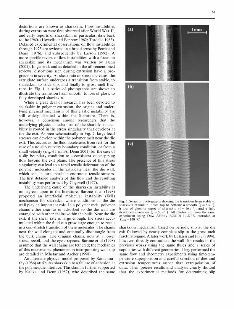
While a great deal of research has been devoted tosharkskin in polymer extrusion, the origins and under-lying physical mechanism of this elastic instability arestill widely debated within the literature. There is,however, a consensus among researchers that theunderlying physical mechanism of the sharkskin insta-bility is rooted in the stress singularity that develops atthe die exit. As seen schematically in Fig. 2, large localstresses can develop within the polymer melt near the dieexit. This occurs as the fluid accelerates from rest for thecase of a no-slip velocity boundary condition, or from asmall velocity (vslip>1 mm/s, Denn 2001) for the case ofa slip boundary condition to a consistent velocity plugflow beyond the exit plane. The presence of this stresssingularity can lead to a rapid tensile deformation of thepolymer molecules in the extrudate near the die wall,which can, in turn, result in enormous tensile stresses.The first detailed analysis of this flow and the resultinginstability was performed by Cogswell (1977).
The underlying cause of the sharkskin instability isnot agreed upon in the literature. Barone et al (1998)proposed an interfacial molecular instability (IMI)mechanism for sharkskin where conditions in the diewall play an important role. In a polymer melt, polymerchains either near to or adsorbed to the die wall areentangled with other chains within the bulk. Near the dieexit, if the shear rate is large enough, the stress accu-mulated within the fluid can grow large enough to resultin a coil-stretch transition of these molecules. The chainsnear the wall elongate and eventually disentangle fromthe bulk chains. The original chains, now at a lowerstress, recoil, and the cycle repeats. Barone et al (1998)assumed that the wall chains are tethered; the mechanicsof this microscopic phenomenon incorporating wall-slipare detailed in Mhetar and Archer (1998).
An alternate physical model proposed by Ramamur-thy (1986) attributes sharkskin to a failure of adhesion atthe polymer/die interface. This claim is further supportedby Kalika and Denn (1987), who described the same
sharkskin mechanism based on periodic slip at the dieexit followed by nearly complete slip in the gross meltfracture regime. A later work by El Kissi and Piau (1994),however, directly contradicts the wall slip results in theprevious works using the same fluids and a series ofcapillaries with different geometries. They performed thesame flow and rheometry experiments using time-tem-perature superposition and careful selection of dies andextrusion temperatures rather than extrapolation ofdata. Their precise results and analysis clearly showedthat the experimental methods for determining slip
Fig. 1 Series of photographs showing the transition from stable tosharkskin extrudate. From top to bottom: a smooth _c ¼ 8 s�1
� �;
b loss of gloss or onset of sharkskin _c ¼ 16 s�1� �
; and c fullydeveloped sharkskin _c ¼ 50 s�1
� �: All photos are from the same
experiment using Dow Affinity EG8100 LLDPE, extruded atTbulk=140 �C
161
velocities do not give conclusive evidence of the existenceof slip at the wall for the linear low-density polyethylene(LLDPE) used by Kalika and Denn (1987) and Rama-murthy (1986). El Kissi and Piau (1994) suggested thatthe slip at the wall reported by the previous authors can,in fact, be attributed to shear thinning, and finally con-cluded that sharkskin in LLDPE is caused instead by acracking of the fluid at the die exit. This mechanism isbased on the hypothesis that local stresses at the die exitexceed the melt strength and cause a surface melt fracturewith a cyclic nature, which is further described by Piauet al (1989) as an exit phenomenon related to the relax-ation of stretch strains.
In spite of the continued debate between some of theabove works, there is a commonality one can infer aboutthe nature of the sharkskinmechanism. The phenomenonof sharkskin is fundamentally rooted in the kinematicsand dynamics of the flownear the capillary die exit and thebuild-up of tensile stress resulting from the stress singu-larity. In particular, numerical simulation results byMackley et al (1998) support this claim and refer to themechanism as a periodic melt rupture at the die exitresulting from large velocity gradients, deformations andstresses, confined to the surface region. In a more experi-mental approach by Dhori et al (1997), the effects of theexit corner were explicitly probed. Dies were dipped in afluoroelastomer additive (Dynamar 9613) known toeliminate sharkskin. The extent of the coating was variedfrom a few millimeters deep to the entire capillary length.Extruding through these capillaries before coating, aftercoating, and finally after the coating was machined off theface of the die, only showed sharkskin, suppression ofsharkskin, and reappearance, respectively. This carefulseries of experiments therefore clearly demonstrated thatthe suppressive coating only affected sharkskin whenpresent at the outermost die exit corner.
Surface quality is important in most extrusionapplications. For example, extruded optical fibers must
be free from surface defects if they are to transmit lighteffectively. Thin fibers that are to be woven into someother final product are difficult to work with if theirsurfaces are not smooth and able to slide past otherfibers easily. Therefore, suppression or elimination andan understanding of sharkskin have practical relevancein that the instability limits the output rate for accept-able extrudate. To this end, there is a large body ofprevious work that addresses the suppression of shark-skin based on the mechanism described above. Alreadymentioned above in the work by Dhori et al (1997),coatings which promote slip in the die/polymer interfacehave been studied extensively. Inn et al (1998) show theeffectiveness of a simple soap solution coating aroundthe die exit in eliminating sharkskin for the extrusion ofpolybutadiene. Previous work has also shown successfulsuppression or complete elimination of sharkskin inpolyethylene extrusion with the use of fluoropolymerpolymer processing additives (PPA). In the work ofMigler et al (2001), PPA is mixed with the LLDPE resinand, with the aid of a sapphire capillary die, is observed tomigrate to the capillary wall where it sticks and inducesslip between itself and the LLDPE. The slip velocity at thewall reduces the stress built up at the die exit, therebypostponing or even eliminating sharkskin altogether.Although successful, the addition of PPAs is not alwaysdesirable in a final LLDPE product. Rather than using aPPA, experiments by Piau et al (1995) use special stainlesssteel dies and polytetrafluoroethylene (PTFE or Teflon)inserts. These PTFE inserts or sleeves also eliminatesharkskin without affecting the composition of the prod-uct. PTFE inserts are, however, limited in their resistanceto high temperature and susceptibility to wear. Alphabrass is another die material shown to induce enough wallslip to suppress sharkskin, as first suggested by Rama-murthy (1986) and later verified by Ghanta et al (1998)and Perez-Gonzalez and Denn (2001).
Rather than addressing the onset of sharkskin bychanging the material at the polymer/die interface, ourresearch focuses on affecting the properties of thepolymer itself towards the goal of reducing polymericstress and deformation at the die exit. By using veryspecific and localized heating/cooling in the die, we willshow that it is possible to locally affect the fluid tem-perature and therefore fluid rheology only near thecapillary wall. The rheological properties of polymersare very sensitive in general to small changes in tem-perature. The theory of time-temperature superpositionallows one to relate changes in viscosity and relaxationtime to changes in temperature (Bird et al 1987). TheArrhenius form of the time-temperature superpositionshift factor is valid for polymer melts far from theirmelting point and is given by
aT ¼kðT ÞT
kðTrefÞTref¼ gðT Þ
gðTrefÞ¼ exp
DH�R
1
T� 1
Tref
� �� �ð1Þ
Fig. 2 Schematic diagram of a capillary die exit geometry showingno-slip wall condition and plug flow in the extrudate, with inherentstress singularity. High local stresses at the die exit plane result instrong deformation of the polymer chains and large tensile stresses
162
where DH is the activation energy, �R is the universal gasconstant, and Tref is an arbitrary reference temperature(Bird et al 1987). Therefore, a strong coupling betweenflow kinematics and the temperature gradients imposedupon the flow through the thermal boundary conditions(die heating/cooling) can exist. A detailed analyticaltreatment of flow through capillaries with die heating ispresented by Winter (1977). This shift factor, aT, allowsfor the creation of master curves of properties such asviscosity from rheology experiments over a wide rangeof temperatures.
The relatively poor thermal conductivity of polymermelts results in the effects of die heating being isolated tothe polymeric fluid near the wall and die exit. Theapproximate thermal boundary layer thickness, dT, canbe related to relevant geometric and physical propertiesof the flow by
dTL/ a � t½ �1=2
L¼ a
�V L
h i1=2¼ Pe�1=2 ð2Þ
where t is the fluid’s residence time in the capillary, L isthe capillary length, and �V is the average velocity. Thefinal scaling argument in Eq. 2 relates the thermalboundary layer thickness, as a fraction of capillarylength, to a Peclet number, a dimensionless group whichrelates the characteristic timescale of thermal diffusionto the characteristic timescale of the flow. Using typicalvalues for average velocity on the order of �V =0.01m/s,capillary length L=10 mm, and a typical value ofthermal diffusivity for LLDPE of a=1.86·10)7 m2/s(Touloukian 1979), gives a result of Pe=537 anddT/L=0.043. A more meaningful result is attained bymultiplying this result by the aspect ratio of our capil-lary, L/D=5, arriving at a final result which indicatesthat the thermal boundary layer grows to roughly 22%of the capillary diameter, D. In terms of the die heating/cooling experiment, this scaling argument highlights theimportance of easily controlled variables such as aspectratio and average velocity. Extruding through a shortercapillary or at higher flow rates will cause the Pecletnumber to increase and thereby minimize the growth ofthe thermal boundary layer even further.
Using the ideas above, let us undertake a brief con-ceptual exercise. Heating the final section of a capillarydie some percent above the bulk working temperaturewill result in a radial temperature profile in the polymermelt across the plane of the die exit. This profile will varyfrom some bulk temperature at the centerline to theelevated capillary wall temperature. If the localizedheating is designed correctly, the majority of the polymermelt in the resulting temperature distribution will be nearthe upstream bulk temperature. Consequently, thisinduced temperature profile will translate into ananalogous distribution of the fluid rheology, resulting ina dramatic reduction in both the viscosity and the
relaxation time of the polymeric fluid near the die wall. Itis our hypothesis that this local modification of the fluidrheology will directly correspond to a respective increasein a critical output rate before the onset of sharkskin.
In extrusion flows, the polymer melt can be exposedto large shear rates over an extended time. As a result ofthe poor thermal conductivity of typical polymericmaterials, the accumulated heat from viscous dissipationcan also have a significant effect on the temperatureprofile in the extrudate and the viscometric properties ofthe fluid. The relative importance of viscous heating canbe quantified by the Nahme number (Bird et al 1987)
Na � g0b�V 2
ktTð3Þ
where g0 is the zero-shear-rate viscosity, kt is the thermalconductivity of the fluid, T is the absolute temperature,and b is the thermal sensitivity of the fluid viscositydefined as
b � Tg0
dgdT
����
����
� �ð4Þ
For the Arrhenius form of time-temperature super-position, this simplifies to b ¼ DH=�RT . Using kt=0.416W/m·K and calculating b=8.38 at a temperature ofT=413 K, gives a relatively small Nahme number ofNa=0.195 for this flow. It has been shown by Winter(1977) that the effect of viscous heating in an extrusionflow is not to heat the fluid near the die where it would beuseful for our purposes, but away from the wall andtowards the centerline. The extent of heating and locationof the maximum temperature is a strong function ofNahme number and residence time. Viscous heating canhave negative effects by raising the temperature of internalregions of the polymer melt above acceptable levels andcould result in polymer degradation (Chung 2000).
The strategy of raising temperature to control oreliminate flow instabilities by decreasing viscosity is notaltogether new. Industrial practices routinely suggestramping up temperature through consecutive heatingzones in screw-type extruders (Chung 2000; Michaeli1984). The opposite approach, die cooling, has also beensuggested in a British patent by Cogswell (1976), inwhich he suggests that sharkskin occurs at a giventemperature, and can be avoided by cooling the surfaceof the extrudate as it exits the die. Work by Santamariaet al (2003) details how cooling of the die lip to justabove the melting point eliminates sharkskin in poly-ethylene by inducing ordering of the molecules, therebyincreasing cohesiveness and reducing the tendency totear and cause sharkskin. Using a Teflon gap, a largeheat sink, and, in some cases, water cooling at the dieexit, Barone et al (1998) were able to demonstrate acorrelation between the period of the sharkskininstability and the die wall exit temperature. Specifically,
163
they found that at a given flow rate, the period increaseswith decreasing die temperature. The experiments ofBarone et al (1998) are quite limited in scope and nomeasurements of the extrudate temperature profile weremade. It is therefore uncertain that the observed shift inthe sharkskin period is not simply a result of increasedbulk temperature of the extrudate. With respect to allthe previous research, our approach to die heating/cooling will utilize a very precise experimental design tolocally affect the extrudate at the die exit allowing us tonot only suppress sharkskin, but also quantify its char-acteristics and eventually control and predict it. Ourresults build upon the conclusions of several aforemen-tioned works and add support to the proposed mecha-nisms for the instability. The practical relevance of ourwork points to an extrusion method that uses a smallamount of added energy in the form of localized dieheating to increase output while minimizing necessarybulk temperatures and subsequent cooling times.
The outline of this paper is as follows. In the followingsection we discuss our experimental setup, fluid rheology,and test protocol. In the next section we present ourresults demonstrating suppression and control ofsharkskin through localized thermal modifications.Finally, we conclude with some implications and sugges-tions for the use of our technique for industrial extrusion.
Experimental
Apparatus
A series of experiments were carried out using a pur-pose-built extruder. In Fig. 3, a schematic diagram of
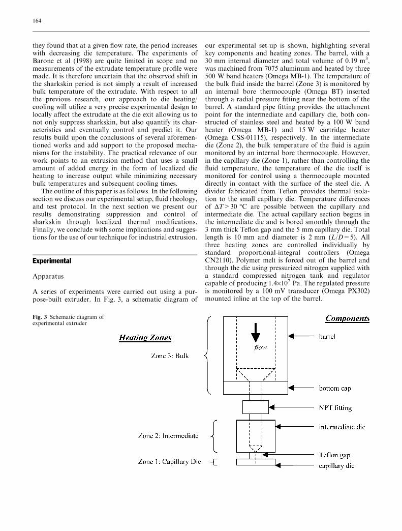
our experimental set-up is shown, highlighting severalkey components and heating zones. The barrel, with a30 mm internal diameter and total volume of 0.19 m3,was machined from 7075 aluminum and heated by three500 W band heaters (Omega MB-1). The temperature ofthe bulk fluid inside the barrel (Zone 3) is monitored byan internal bore thermocouple (Omega BT) insertedthrough a radial pressure fitting near the bottom of thebarrel. A standard pipe fitting provides the attachmentpoint for the intermediate and capillary die, both con-structed of stainless steel and heated by a 100 W bandheater (Omega MB-1) and 15 W cartridge heater(Omega CSS-01115), respectively. In the intermediatedie (Zone 2), the bulk temperature of the fluid is againmonitored by an internal bore thermocouple. However,in the capillary die (Zone 1), rather than controlling thefluid temperature, the temperature of the die itself ismonitored for control using a thermocouple mounteddirectly in contact with the surface of the steel die. Adivider fabricated from Teflon provides thermal isola-tion to the small capillary die. Temperature differencesof DT>30 �C are possible between the capillary andintermediate die. The actual capillary section begins inthe intermediate die and is bored smoothly through the3 mm thick Teflon gap and the 5 mm capillary die. Totallength is 10 mm and diameter is 2 mm (L/D=5). Allthree heating zones are controlled individually bystandard proportional-integral controllers (OmegaCN2110). Polymer melt is forced out of the barrel andthrough the die using pressurized nitrogen supplied witha standard compressed nitrogen tank and regulatorcapable of producing 1.4·107 Pa. The regulated pressureis monitored by a 100 mV transducer (Omega PX302)mounted inline at the top of the barrel.
Fig. 3 Schematic diagram ofexperimental extruder
164
Working material
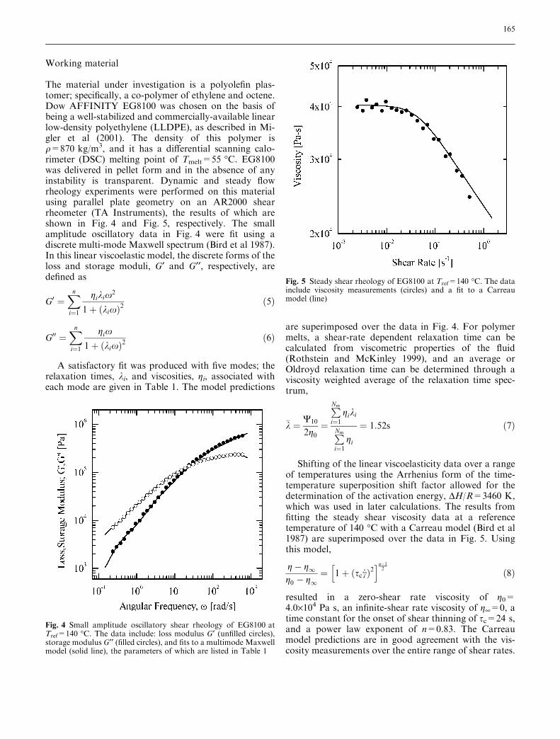
The material under investigation is a polyolefin plas-tomer; specifically, a co-polymer of ethylene and octene.Dow AFFINITY EG8100 was chosen on the basis ofbeing a well-stabilized and commercially-available linearlow-density polyethylene (LLDPE), as described in Mi-gler et al (2001). The density of this polymer isq=870 kg/m3, and it has a differential scanning calo-rimeter (DSC) melting point of Tmelt=55 �C. EG8100was delivered in pellet form and in the absence of anyinstability is transparent. Dynamic and steady flowrheology experiments were performed on this materialusing parallel plate geometry on an AR2000 shearrheometer (TA Instruments), the results of which areshown in Fig. 4 and Fig. 5, respectively. The smallamplitude oscillatory data in Fig. 4 were fit using adiscrete multi-mode Maxwell spectrum (Bird et al 1987).In this linear viscoelastic model, the discrete forms of theloss and storage moduli, G¢ and G¢¢, respectively, aredefined as
G0 ¼Xn
i¼1
gikix2
1þ kixð Þ2ð5Þ
G00 ¼Xn
i¼1
gix
1þ kixð Þ2ð6Þ
A satisfactory fit was produced with five modes; therelaxation times, ki, and viscosities, gi, associated witheach mode are given in Table 1. The model predictions
are superimposed over the data in Fig. 4. For polymermelts, a shear-rate dependent relaxation time can becalculated from viscometric properties of the fluid(Rothstein and McKinley 1999), and an average orOldroyd relaxation time can be determined through aviscosity weighted average of the relaxation time spec-trum,
�k ¼ W10
2g0¼
PNm
i¼1giki
PNm
i¼1gi
¼ 1:52s ð7Þ
Shifting of the linear viscoelasticity data over a rangeof temperatures using the Arrhenius form of the time-temperature superposition shift factor allowed for thedetermination of the activation energy, DH/R=3460 K,which was used in later calculations. The results fromfitting the steady shear viscosity data at a referencetemperature of 140 �C with a Carreau model (Bird et al1987) are superimposed over the data in Fig. 5. Usingthis model,
g� g1g0 � g1
¼ 1þ sc _cð Þ2h in�1
2 ð8Þ
resulted in a zero-shear rate viscosity of g0=4.0·104 Pa s, an infinite-shear rate viscosity of g¥=0, atime constant for the onset of shear thinning of sc=24 s,and a power law exponent of n=0.83. The Carreaumodel predictions are in good agreement with the vis-cosity measurements over the entire range of shear rates.
Fig. 4 Small amplitude oscillatory shear rheology of EG8100 atTref=140 �C. The data include: loss modulus G¢ (unfilled circles),storage modulus G¢¢ (filled circles), and fits to a multimode Maxwellmodel (solid line), the parameters of which are listed in Table 1
Fig. 5 Steady shear rheology of EG8100 at Tref=140 �C. The datainclude viscosity measurements (circles) and a fit to a Carreaumodel (line)
165
Experimental protocol
The extruder was initially calibrated by generating flowcurves, several of which will be presented in the fol-lowing sections. Pressure drop, controlled via the regu-lator on the nitrogen tank, was ramped up while themass flow rate of extruded polymer was measured. Thelatter was done by weighing timed samples of extrudate,using an accurate balance with a sensitivity of 0.001 g(Mettler AC100), collected at a constant pressure drop.Flow curves were generated at various temperatureconditions, where bulk temperature is controlled inZones 2 and 3, and die heating or cooling is done withprecise control at Zone 1. We will show through tem-perature measurements that this precise control affectsonly a very small portion of the polymer melt near thecapillary wall as it exits the die.
Temperature profile measurements of the extrudatewere performed using a micro-positioning stage adaptedto hold a K-type thermocouple junction at the end of ahorizontally-oriented protection tube. The exposed
junction was marched across the exit plane of the cap-illary die. The center of the thermocouple junction wasaligned to be tangent with the exit plane of the capillary,resulting in no upstream effects within the capillary butstill capturing the temperature of the extrudate directlyat the exit plane. The thermocouple junction had adiameter of Dtc=0.35 mm, resulting in a spatially-averaged temperature measurement of the polymer melt.These measurements are invasive and, although greatcare is taken during positioning so that the effect iscompletely downstream of the die exit plane, they canaffect the flow as we are trying to measure it. Futureexperiments are planned with a non-invasive tempera-ture measurement technique such as the Dual EmissionLaser Induced Fluorescence (DELIF), described inCoppeta and Rogers (1998). These temperature mea-surements served to confirm the thermal gradientbetween the extrudate centerline and wall temperature.
Qualitative flow visualization of the extrudate uponexiting the die was done using a CCD camera (HitachiKP-M22 N) and video zoom microscope lens with anincreased depth of field (Edmund VZM 450i). Quanti-tative characterization of the extrudate surface showingthe sharkskin instability was done optically. Still imagesof cooled extrudate samples were taken from framescaptured with a CCD camera mated to a microscope(Olympus Vanox-T). Using backlighting, the profile ofthe extrudate was captured and processed using an edgedetection routine we developed in MATLAB. The rou-tine utilized a max/min function and fast-Fouriertransform to calculate the average amplitude anddominant wavelength of the nearly periodic sharkskinprofile.
Results and discussion
Flow curves and effects of die heating
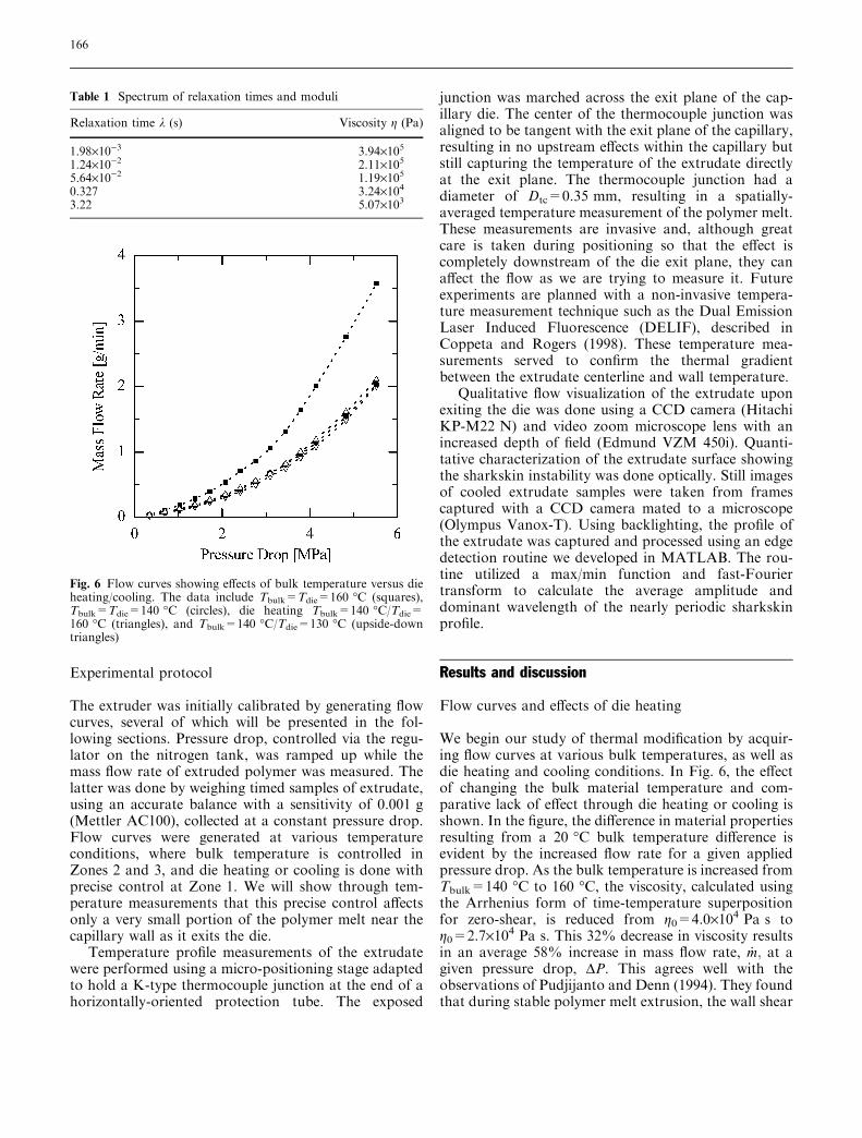
We begin our study of thermal modification by acquir-ing flow curves at various bulk temperatures, as well asdie heating and cooling conditions. In Fig. 6, the effectof changing the bulk material temperature and com-parative lack of effect through die heating or cooling isshown. In the figure, the difference in material propertiesresulting from a 20 �C bulk temperature difference isevident by the increased flow rate for a given appliedpressure drop. As the bulk temperature is increased fromTbulk=140 �C to 160 �C, the viscosity, calculated usingthe Arrhenius form of time-temperature superpositionfor zero-shear, is reduced from g0=4.0·104 Pa s tog0=2.7·104 Pa s. This 32% decrease in viscosity resultsin an average 58% increase in mass flow rate, _m; at agiven pressure drop, DP. This agrees well with theobservations of Pudjijanto and Denn (1994). They foundthat during stable polymer melt extrusion, the wall shear
Fig. 6 Flow curves showing effects of bulk temperature versus dieheating/cooling. The data include Tbulk=Tdie=160 �C (squares),Tbulk=Tdie=140 �C (circles), die heating Tbulk=140 �C/Tdie=160 �C (triangles), and Tbulk=140 �C/Tdie=130 �C (upside-downtriangles)
Table 1 Spectrum of relaxation times and moduli
Relaxation time k (s) Viscosity g (Pa)
1.98·10)3 3.94·1051.24·10)2 2.11·1055.64·10)2 1.19·1050.327 3.24·1043.22 5.07·103
166
stress, swall ¼ DP D=4Lð Þ; increased as swall / _c0:69app , wherethe nominal uncorrected value of the apparent shear rateis _capp ¼ 8�V =D. Here, 4 _m
�qpD2 is the average velocity
calculated from the measured mass flow rate. From theexperimental observations of Pudjijanto and Denn(1994), we would expect a 59% increase in the observedmass flow rate. In contrast to changing the bulk tem-perature, the addition of die heating or cooling to theexperiment at Tbulk=140 �C produces a negligible effecton the flow curve. Therefore, although the die is beingheated to Tdie=160 �C or cooled to Tdie=130 �C, theseexperiments clearly show that only the very outermostpolymer melt in the die is being heated or cooled beyondthe centerline temperature while the bulk properties ofthe fluid remain unaffected. These qualitative observa-tions of the localization of our thermal modificationswill be reinforced with precise temperature profile mea-surements.
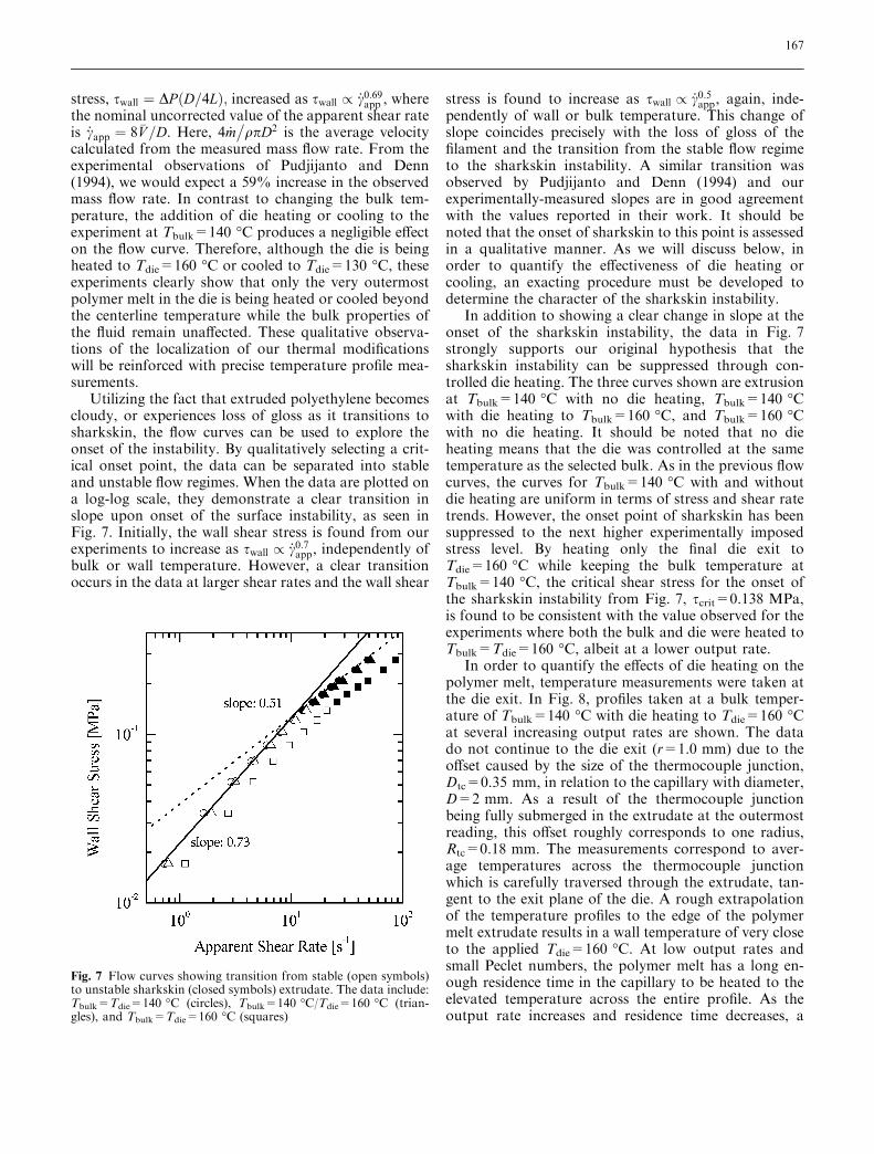
Utilizing the fact that extruded polyethylene becomescloudy, or experiences loss of gloss as it transitions tosharkskin, the flow curves can be used to explore theonset of the instability. By qualitatively selecting a crit-ical onset point, the data can be separated into stableand unstable flow regimes. When the data are plotted ona log-log scale, they demonstrate a clear transition inslope upon onset of the surface instability, as seen inFig. 7. Initially, the wall shear stress is found from ourexperiments to increase as swall / _c0:7app, independently ofbulk or wall temperature. However, a clear transitionoccurs in the data at larger shear rates and the wall shear
stress is found to increase as swall / _c0:5app, again, inde-pendently of wall or bulk temperature. This change ofslope coincides precisely with the loss of gloss of thefilament and the transition from the stable flow regimeto the sharkskin instability. A similar transition wasobserved by Pudjijanto and Denn (1994) and ourexperimentally-measured slopes are in good agreementwith the values reported in their work. It should benoted that the onset of sharkskin to this point is assessedin a qualitative manner. As we will discuss below, inorder to quantify the effectiveness of die heating orcooling, an exacting procedure must be developed todetermine the character of the sharkskin instability.
In addition to showing a clear change in slope at theonset of the sharkskin instability, the data in Fig. 7strongly supports our original hypothesis that thesharkskin instability can be suppressed through con-trolled die heating. The three curves shown are extrusionat Tbulk=140 �C with no die heating, Tbulk=140 �Cwith die heating to Tbulk=160 �C, and Tbulk=160 �Cwith no die heating. It should be noted that no dieheating means that the die was controlled at the sametemperature as the selected bulk. As in the previous flowcurves, the curves for Tbulk=140 �C with and withoutdie heating are uniform in terms of stress and shear ratetrends. However, the onset point of sharkskin has beensuppressed to the next higher experimentally imposedstress level. By heating only the final die exit toTdie=160 �C while keeping the bulk temperature atTbulk=140 �C, the critical shear stress for the onset ofthe sharkskin instability from Fig. 7, scrit=0.138 MPa,is found to be consistent with the value observed for theexperiments where both the bulk and die were heated toTbulk=Tdie=160 �C, albeit at a lower output rate.
In order to quantify the effects of die heating on thepolymer melt, temperature measurements were taken atthe die exit. In Fig. 8, profiles taken at a bulk temper-ature of Tbulk=140 �C with die heating to Tdie=160 �Cat several increasing output rates are shown. The datado not continue to the die exit (r=1.0 mm) due to theoffset caused by the size of the thermocouple junction,Dtc=0.35 mm, in relation to the capillary with diameter,D=2 mm. As a result of the thermocouple junctionbeing fully submerged in the extrudate at the outermostreading, this offset roughly corresponds to one radius,Rtc=0.18 mm. The measurements correspond to aver-age temperatures across the thermocouple junctionwhich is carefully traversed through the extrudate, tan-gent to the exit plane of the die. A rough extrapolationof the temperature profiles to the edge of the polymermelt extrudate results in a wall temperature of very closeto the applied Tdie=160 �C. At low output rates andsmall Peclet numbers, the polymer melt has a long en-ough residence time in the capillary to be heated to theelevated temperature across the entire profile. As theoutput rate increases and residence time decreases, a
Fig. 7 Flow curves showing transition from stable (open symbols)to unstable sharkskin (closed symbols) extrudate. The data include:Tbulk=Tdie=140 �C (circles), Tbulk=140 �C/Tdie=160 �C (trian-gles), and Tbulk=Tdie=160 �C (squares)
167
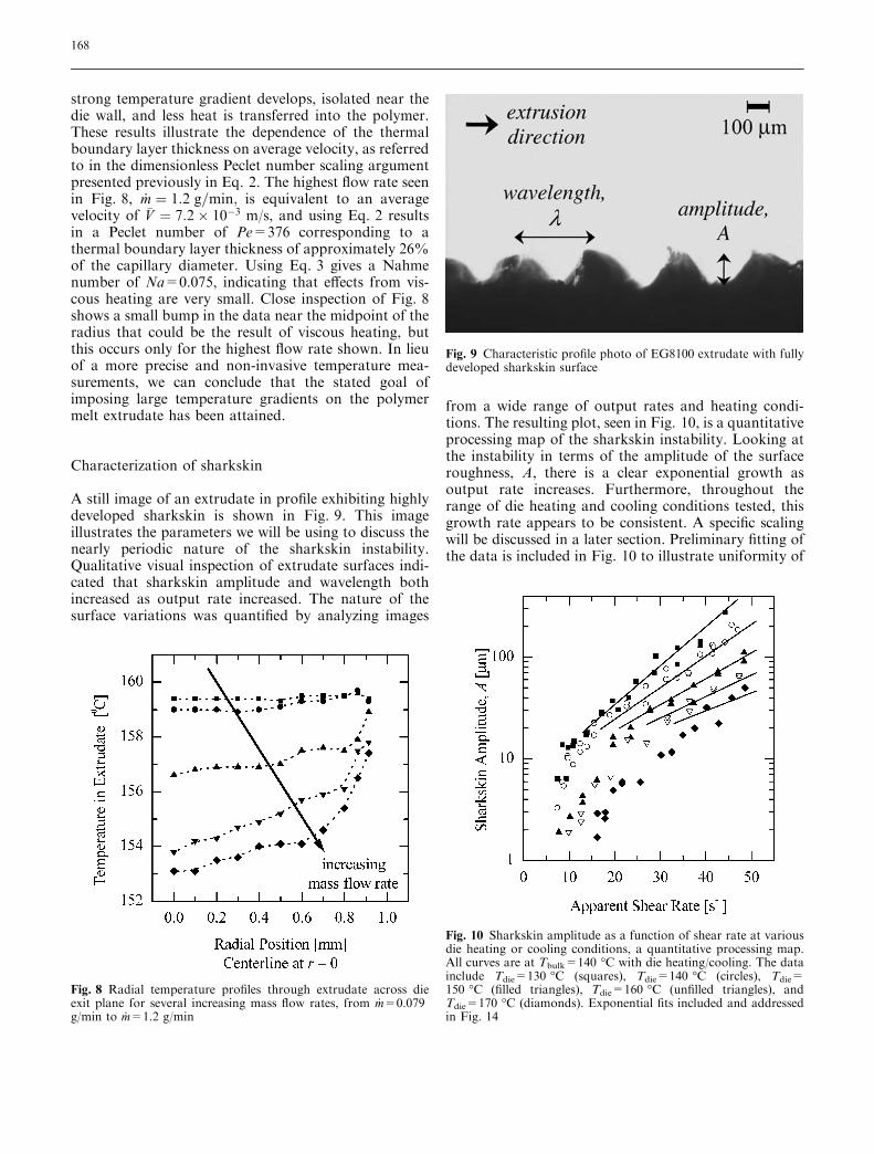
strong temperature gradient develops, isolated near thedie wall, and less heat is transferred into the polymer.These results illustrate the dependence of the thermalboundary layer thickness on average velocity, as referredto in the dimensionless Peclet number scaling argumentpresented previously in Eq. 2. The highest flow rate seenin Fig. 8, _m ¼ 1:2 g=min; is equivalent to an averagevelocity of �V ¼ 7:2� 10�3 m/s, and using Eq. 2 resultsin a Peclet number of Pe=376 corresponding to athermal boundary layer thickness of approximately 26%of the capillary diameter. Using Eq. 3 gives a Nahmenumber of Na=0.075, indicating that effects from vis-cous heating are very small. Close inspection of Fig. 8shows a small bump in the data near the midpoint of theradius that could be the result of viscous heating, butthis occurs only for the highest flow rate shown. In lieuof a more precise and non-invasive temperature mea-surements, we can conclude that the stated goal ofimposing large temperature gradients on the polymermelt extrudate has been attained.
Characterization of sharkskin
A still image of an extrudate in profile exhibiting highlydeveloped sharkskin is shown in Fig. 9. This imageillustrates the parameters we will be using to discuss thenearly periodic nature of the sharkskin instability.Qualitative visual inspection of extrudate surfaces indi-cated that sharkskin amplitude and wavelength bothincreased as output rate increased. The nature of thesurface variations was quantified by analyzing images
from a wide range of output rates and heating condi-tions. The resulting plot, seen in Fig. 10, is a quantitativeprocessing map of the sharkskin instability. Looking atthe instability in terms of the amplitude of the surfaceroughness, A, there is a clear exponential growth asoutput rate increases. Furthermore, throughout therange of die heating and cooling conditions tested, thisgrowth rate appears to be consistent. A specific scalingwill be discussed in a later section. Preliminary fitting ofthe data is included in Fig. 10 to illustrate uniformity of
Fig. 8 Radial temperature profiles through extrudate across dieexit plane for several increasing mass flow rates, from _m=0.079g/min to _m=1.2 g/min
Fig. 9 Characteristic profile photo of EG8100 extrudate with fullydeveloped sharkskin surface
Fig. 10 Sharkskin amplitude as a function of shear rate at variousdie heating or cooling conditions, a quantitative processing map.All curves are at Tbulk=140 �C with die heating/cooling. The datainclude Tdie=130 �C (squares), Tdie=140 �C (circles), Tdie=150 �C (filled triangles), Tdie=160 �C (unfilled triangles), andTdie=170 �C (diamonds). Exponential fits included and addressedin Fig. 14
168
the data between temperature conditions in the givenwindow. This scaling suggests that the consistent fit isvalid for shear rates far from the onset conditions ofsharkskin; the initial growth from submicron roughnessand smooth surfaces to sharkskin is much stronger. Thescatter in the data is due primarily to the 1 lm resolu-tion of the images used.
An additional feature of the data in Fig. 10 is thelack of hysteresis, explored in a series of experimentsperformed to determine the nature of the instability.The shear rate at which the polymer was extruded wasinitially ramped up and then back down. Samples ofthe extrudate were collected along both paths of theflow curve. The resulting measurements of the ampli-tude of the surface roughness demonstrated no sig-nificant deviation indicative of hysteresis. This resultsuggests that the sharkskin instability is a supercriticalbifurcation (Iooss and Joseph 1980). Our work con-tradicts the results of Bertola et al (2003) and Meu-lenbroek et al (2003), who investigated the extrusionof a polyvinyl alcohol sodium tetraborate solution andfound the amplitude growth of the sharkskin insta-bility was hysteretic with shear rate. Based on theresults of their experiments and the stability analysisof Meulenbroek et al (2003), Bertola et al (2003) claimthat there is one fundamental intrinsic route to thesharkskin instability and that the instability hasthe characteristics of a weakly subcritical bifurcation.The origin of this discrepancy in our experiments isunclear and, to our knowledge, no other sourceindicates that sharkskin has the characteristics of asubcritical bifurcation.
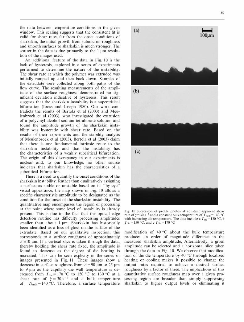
There is a need to quantify the onset conditions of thesharkskin instability. Rather than qualitatively assigninga surface as stable or unstable based on its ‘‘by eye’’visual appearance, the map shown in Fig. 10 allows aspecific characteristic amplitude to be designated as thecondition for the onset of the sharkskin instability. Thequantitative map encompasses the region of processingat the point where some level of instability is alreadypresent. This is due to the fact that the optical edgedetection routine has difficulty processing amplitudessmaller than about 1 lm. Sharkskin has historicallybeen identified as a loss of gloss on the surface of theextrudate. Based on our qualitative inspection, thiscorresponds to a surface roughness of approximatelyA�10 lm. If a vertical slice is taken through the data,thereby holding the shear rate fixed, the amplitude isfound to decrease as the degree of die heating isincreased. This can be seen explicity in the series ofimages presented in Fig. 11. These images show adecrease in surface roughness from A=90 lm to 25 lmto 9 lm as the capillary die wall temperature is de-creased from Tdie=170 �C to 150 �C to 130 �C at ashear rate of _c ¼ 30 s�1 and a bulk temperatureof Tbulk=140 �C. Therefore, a surface temperature
modification of 40 �C about the bulk temperatureproduces an order of magnitude difference in themeasured sharkskin amplitude. Alternatively, a givenamplitude can be selected and a horizontal slice takenthrough the data in Fig. 10. We observe that modifica-tion of the die temperature by 40 �C through localizedheating or cooling makes it possible to change theoutput rates required to achieve a desired surfaceroughness by a factor of three. The implications of thisquantitative surface roughness map over a given pro-cessing region are broader than simply suppressingsharkskin to higher output levels or eliminating it
Fig. 11 Succession of profile photos at constant apparent shearrate of _c=30 s)1 and a constant bulk temperature of Tbulk=140 �Cwith increasing die temperature. The data include a Tdie=130 �C, bTdie=150 �C, and c Tdie=170 �C
169
entirely at a specific condition, flow rate, or pressuredrop. Through the use of controlled die heating, thepolymer melt extrudate can be processed at a selectedoperating condition in terms of stress and shear levels,allowing one to ‘‘dial in’’ a specific amplitude and imparta desired functionality to the surface.
Mechanism of sharkskin
The effectiveness of isolated heating at the die wall givessome insight into the mechanism of the sharkskininstability. Our results lend support to the theory thatsharkskin originates in the interaction of the polymerwith the die wall and local stresses at the die exit. Tofurther quantify this dependence, a local Deborah andWeissenberg number are formed based on the conditionsat the capillary die wall:
Delocal ¼ k Tdieð Þf ð9Þ
W ilocal ¼ k Tdieð Þ _capp ð10Þ
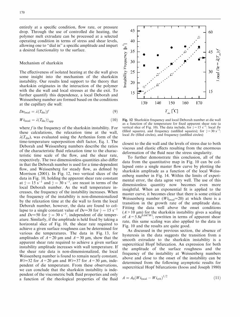
where f is the frequency of the sharkskin instability. Forthese calculations, the relaxation time at the wall,k(Tdie), was evaluated using the Arrhenius form of thetime-temperature superposition shift factor, Eq. 1. TheDeborah and Weissenberg numbers describe the ratiosof the characteristic fluid relaxation time to the charac-teristic time scale of the flow, and the shear rate,respectively. The two dimensionless quantities also differin that the Deborah number is used for a time-dependentflow, and Weissenberg for steady flow, as defined byMorrison (2001). In Fig. 12, two vertical slices of thedata in Fig. 10, holding the apparent shear rate constantat _c ¼ 15 s�1 and _c ¼ 30 s�1; are recast in terms of thelocal Deborah number. As the wall temperature in-creases, the frequency of the instability increases. Whenthe frequency of the instability is non-dimensionalizedby the relaxation time at the die wall to form the localDeborah number, however, the data are found to col-lapse to a single constant value of De.38 for _c ¼ 15 s�1
and De.50 for _c ¼ 30 s�1; independent of die temper-ature. Similarly, if the amplitude is held fixed by taking ahorizontal slice of Fig. 10, the shear rate required toachieve a given surface roughness can be determined forvarious die temperatures. The data in Fig. 13, foramplitudes of A=20 lm and A=30 lm, show that theapparent shear rate required to achieve a given surfaceinstability amplitude increases with wall temperature. Ifthe shear rate data is non-dimensionalized, the localWeissenberg number is found to remain nearly constant,Wi.32 for A=20 lm and Wi.37 for A=30 lm, inde-pendent of die temperature. From these observations,we can conclude that the sharkskin instability is inde-pendent of the viscometric bulk fluid properties and onlya function of the rheological properties of the fluid
closest to the die wall and the levels of stress due to bothviscous and elastic effects resulting from the enormousdeformation of the fluid near the stress singularity.
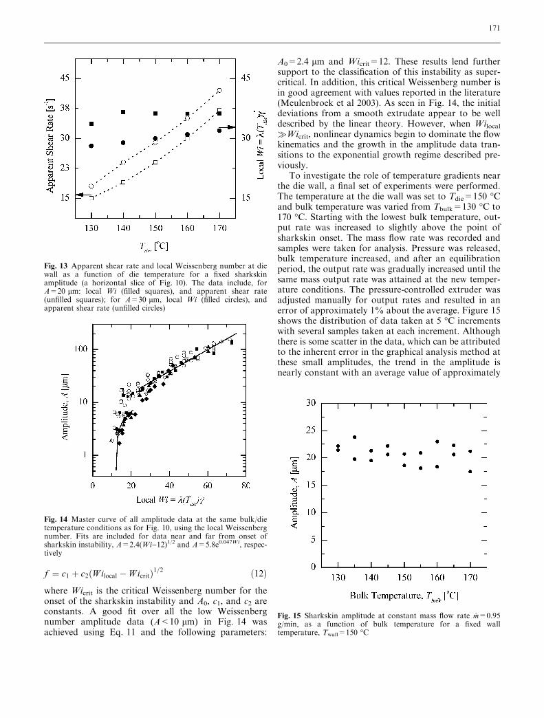
To further demonstrate this conclusion, all of thedata from the quantitative map in Fig. 10 can be col-lapsed onto a single master flow curve by plotting thesharkskin amplitude as a function of the local Weiss-enberg number in Fig. 14. Within the limits of experi-mental error, the data agree very well. The use of thisdimensionless quantity now becomes even moreinsightful. When an exponential fit is applied to themaster curve, it becomes clear that there is some criticalWeissenberg number (Wilocal.20) at which there is atransition in the growth rate of the amplitude data.Fitting the data well above the onset conditions(A>10 lm) for the sharkskin instability gives a scalingof A=5.8e0.047Wi; rewritten in terms of apparent shearrate, this same scaling was also applied to the data inFig. 10 and the results are quite good.
As discussed in the previous section, the absence ofhysteresis in the data suggests the transition from asmooth extrudate to the sharkskin instability is asupercritical Hopf bifurcation. An expression for boththe amplitude of the surface roughness and thefrequency of the instability at Weissenberg numbersabove and close to the onset of the instability can bedetermined from the following asymptotic results forsupercritical Hopf bifurcations (Iooss and Joseph 1980)
A ¼ A0 W ilocal � W icritð Þ1=2 ð11Þ
Fig. 12 Sharkskin frequency and local Deborah number at die wallas a function of die temperature for fixed apparent shear rate (avertical slice of Fig. 10). The data include, for _c=15 s)1: local De(filled squares), and frequency (unfilled squares); for _c=30 s)1:local De (filled circles), and frequency (unfilled circles)
170
f ¼ c1 þ c2 W ilocal � W icritð Þ1=2 ð12Þ
where Wicrit is the critical Weissenberg number for theonset of the sharkskin instability and A0, c1, and c2 areconstants. A good fit over all the low Weissenbergnumber amplitude data (A<10 lm) in Fig. 14 wasachieved using Eq. 11 and the following parameters:
A0=2.4 lm and Wicrit=12. These results lend furthersupport to the classification of this instability as super-critical. In addition, this critical Weissenberg number isin good agreement with values reported in the literature(Meulenbroek et al 2003). As seen in Fig. 14, the initialdeviations from a smooth extrudate appear to be welldescribed by the linear theory. However, when Wilocal�Wicrit, nonlinear dynamics begin to dominate the flowkinematics and the growth in the amplitude data tran-sitions to the exponential growth regime described pre-viously.
To investigate the role of temperature gradients nearthe die wall, a final set of experiments were performed.The temperature at the die wall was set to Tdie=150 �Cand bulk temperature was varied from Tbulk=130 �C to170 �C. Starting with the lowest bulk temperature, out-put rate was increased to slightly above the point ofsharkskin onset. The mass flow rate was recorded andsamples were taken for analysis. Pressure was released,bulk temperature increased, and after an equilibrationperiod, the output rate was gradually increased until thesame mass output rate was attained at the new temper-ature conditions. The pressure-controlled extruder wasadjusted manually for output rates and resulted in anerror of approximately 1% about the average. Figure 15shows the distribution of data taken at 5 �C incrementswith several samples taken at each increment. Althoughthere is some scatter in the data, which can be attributedto the inherent error in the graphical analysis method atthese small amplitudes, the trend in the amplitude isnearly constant with an average value of approximately
Fig. 14 Master curve of all amplitude data at the same bulk/dietemperature conditions as for Fig. 10, using the local Weissenbergnumber. Fits are included for data near and far from onset ofsharkskin instability, A=2.4(Wi)12)1/2 and A=5.8e0.047Wi, respec-tively
Fig. 15 Sharkskin amplitude at constant mass flow rate _m=0.95g/min, as a function of bulk temperature for a fixed walltemperature, Twall=150 �C
Fig. 13 Apparent shear rate and local Weissenberg number at diewall as a function of die temperature for a fixed sharkskinamplitude (a horizontal slice of Fig. 10). The data include, forA=20 lm: local Wi (filled squares), and apparent shear rate(unfilled squares); for A=30 lm, local Wi (filled circles), andapparent shear rate (unfilled circles)
171
A=20 lm. These experiments demonstrate that thecharacter of the sharkskin amplitude remains constantin the presence of changing temperature gradients and isa function only of the actual temperature at the die wall.
Conclusions
Precise and localized die heating has been shown tosuppress the onset of the sharkskin surface instability inthe extrusion of LLDPE. Sharkskin has also beenquantitatively characterized as a function of the pro-cessing conditions, showing that the severity of the dis-tortions grows with an exponential trend with increasingapparent shear rate at all die heating conditions. Theresulting quantitative processing map for sharkskinamplitude is a useful tool that allows for the precisecontrol of sharkskin surface distortions through themodification of die wall temperature. Analysis ofthe same quantitative map gives fundamental support tothe mechanism of sharkskin being inherent in conditionsat the die wall, and nearly independent of conditions inthe bulk.
These results have some interesting practical impli-cations to the extrusion of LLDPE and other polymers
that exhibit the sharkskin instability. Bulk processingtemperatures can be much lower than those needed tosuppress the instability. The heating of a very smallportion of the die at the exit provides the same benefit asprocessing the entire bulk at that higher temperature.Bulk processes can be cooler and more energy efficient,while cooling times of the polymer melt extrudate areminimized. Precise control of sharkskin as alluded to inthe preceding experimental results leads to future theo-retical applications such as the extrusion of productswith specifically designed or even varying surfaceroughness. In film blowing or sheet extrusion, inner andouter dies could produce surfaces smooth on one sideand rough on the other. On a qualitative level, Rutgerset al (2002) have already stated that temperature gradi-ents between the inner and outer die lips in a filmblowing application produce smooth and sharkskinsurfaces on the respective surfaces of a bubble. Furtherdevelopment of temperature control systems could resultin dies that would respond quickly and could patternsurfaces as they were extruded.
Acknowledgements The authors would like to acknowledge theExecutive Area for Research for partial support of this researchthrough a Healy Endowment Grant.
References
Barone JR, Plucktaveesak N, Wang SQ(1998) Interfacial molecular instabilitymechanism for sharkskin phenomenonin capillary extrusion of linearpolyethylenes. J Rheol 42:813–832
Bertola V, Meulenbroek B, Wagner C,Storm C, Morozov A, Saarloos Wv,Bonn D (2003) Experimental evidencefor an intrinsic route to polymer meltfracture phenomena: A nonlinearinstability of viscoelastic Poiseuille flow.Phys Rev Lett 90:114502(4)
Bird RB, Armstrong BC, Hassager O(1987) Dynamics of polymeric liquids:Vol 1: Fluid mechanics. Wiley, NewYork
Chung CI (2000) Extrusion of polymers:theory and practice. Carl Hanser,Munich, Germany
Cogswell FN (1976) A method for reducingsharkskin on extruded polymericmaterial. British Patent #1 441 586
Cogswell FN (1977) Stretching flowinstabilities at the exits of extrusion dies.J Non-Newton Fluid 2:37–47
Coppeta J, Rogers C (1998) Dual emissionlaser induced fluorescence for directplanar scalar behavior measurements.Exp Fluids 25:1-15
Denn MM (2001) Extrusion instabilitiesand wall slip. Annu Rev Fluid Mech33:265–287
Dhori PK, Jeyaseelan RS, Giacomin AJ,Slattery JC (1997) Common line motionIII: implication in polymer extrusion.J Non-Newton Fluid 71:231–243
El Kissi N, Piau J-M (1994) Adhesion oflinear low density polyethylene for flowregimes with sharkskin. J. Rheol38:1447–1463
Ghanta VG, Riise BL, Denn MM (1998)Disappearance of extrusion instabilitiesin brass capillary dies. J Rheol43:435–442
Howells ER, Benbow JJ (1962) Flowdefects in polymer melts. T J Plast I30:240–253
Inn YW, Fisher RJ, Shaw MT (1998)Visual observation of development ofsharkskin melt fracture in polybutadieneextrusion. Rheol Acta 37:573–582
Iooss G, Joseph D (1980) Elementarystability and bifurcation theory.Springer, Berlin Heidelberg New York
Kalika DS, Denn MM (1987) Wall slip andextrudate distortion in linear low-den-sity polyethylene. J Rheol 31:815–834
Larson RG (1992) Instabilities inviscoelastic flows. Rheol Acta31:213–263
Mackley M, Rutgers R, Gilbert D (1998)Surface instabilities during the extrusionof linear low density polyethylene.J Non-Newton Fluid 76:281–297
Meulenbroek B, Storm C, Bertola V,Wagner C, Bonn D, Saarloos Wv (2003)Intrinsic route to melt fracture inpolymer extrusion: A weakly nonlinearsubcritical instability in viscoelasticPoiseuille flow. Phys Rev Lett90:024502(4)
Mhetar V, Archer LA (1998) Slip inentangled polymer melts. 1. Generalfeatures. Macromolecules 31:8607–8616
Michaeli W (1984) Extrusion dies: designand engineering computations. CarlHanser/Macmillan, Munich, Germany
Migler KB, Lavalee C, Dillon MP, WoodsSS, Gettinger CL (2001) Visualizing theelimination of sharkskin throughfluoropolymer additives: Coating andpolymer-polymer slippage. J Rheol45:565–581
Morrison FA (2001) Understandingrheology. Oxford University Press, NewYork
172
Perez-Gonzalez J, Denn MM (2001) Flowenhancement in the continuousextrustion of linear low-densitypolyethylene. Ind Eng Chem Res40:4309–4316
Petrie CJS, Denn MM (1976) Instabilitesin polymer processing. AIChE J22:209–236
Piau JM, El Kissi N, Tremblay B (1989)Influence of upstream instabilities andwall slip on melt fracture and sharkskinphenomena during silicones extrusionthrough orifice dies. J Non-NewtonFluid 34:145–180
Piau J-M, Kissi NE, Toussant F, MezghaniA (1995) Distortion of polymer meltextrudates and their elimination usingslippery surfaces. Rheol Acta 34:40–57
Pudjijanto S, Denn MM (1994) A stable‘‘island’’ in the slip-stick region of linearlow-density polyethylene. J Rheol38:1735–1744
Ramamurthy AV (1986) Wall slip in vis-cous fluids and influence of materials ofconstruction. J Rheol 30:337–357
Rothstein JP, McKinley GH (1999)Extensional flow of a polystyrene Bogerfluid through a 4:1:4 axisymmetriccontraction/expansion. J Non-NewtonFluid 86:61–88
Rutgers R, Clemeur N, Husny J (2002) Theprediction of sharkskin instabilityobserved during film blowing. Int PolymProc 17:214–222
Santamaria A, Fernandez M, Sanz E,Lafuente P, Munoz-Escalona A (2003)Postponing sharkskin of metallocenepolyethylenes at low temperatures: theeffect of molecular parameters. Polymer44:2473–2480
Tordella JP (1963) Unstable flow of moltenpolymers: A second site of melt fracture.J Appl Polym Sci 7:215–229
Touloukian YS (1979) Thermophysicalproperties of matter; the TPRC dataseries. IFI/Plenum, New York
Winter HH (1977) Viscous dissipation inshear flows of molten polymers. AdvHeat Transfer 13:205–267
173