Embed Size (px)
Citation preview
Control panel for air to water Inverter heat pump
Pannello di controllo per pompa di calore Inverter aria / acqua
Panneau de contrôle pour pompe à chaleur Inverter air / eau
37.4254.088.00 01/2018
EG
I
OPERATING INSTRUCTIONS
ISTRUZIONI D’USO
MODE D’EMPLOI F
2
EG
2
Contents 1 - Presentation of control elements ............................................................................................ 2 2 - Operation ................................................................................................................................. 3 3 - Settings ................................................................................................................................... 5 4 - Graphs ................................................................................................................................... 10
1 - Presentation of Control elements
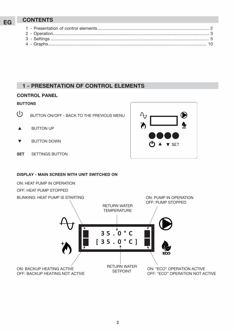
Control Panel
BUttons
BUTTON ON/OFF - BACK TO THE PREVIOUS MENU
s BUTTON UP
t BUTTON DOWN
set SETTINGS BUTTON
3 5 . 0 ° C[ 3 5 . 0 ° C ]
ON: HEAT PUMP IN OPERATION
OFF: HEAT PUMP STOPPED
BLINKING: HEAT PUMP IS STARTING ON: PUMP IN OPERATIONOFF: PUMP STOPPED
ON: BACKUP HEATING ACTIVEOFF: BACKUP HEATING NOT ACTIVE
ON: “ECO” OPERATION ACTIVEOFF: “ECO” OPERATION NOT ACTIVE
RETURN WATER TEMPERATURE
RETURN WATER SETPOINT
DisPlaY - main sCreen WitH Unit sWitCHeD on

3
EG
3
2 - oPeration
2.1 - sWitCHinG tHe Unit on/off
• Toturnontheunit,pressandholdthebutton for3seconds.Thefollowingtwoscreenswillappear sequentially:
- - - -- - - -
• Whentheunitispowered,thefollowingscreenappears:
• Thenthemainscreenwillappear:
3 5 . 0 ° C[ 3 5 . 0 ° C ]
m o d e l r 0 1D I S P L A Y r 0 1
UNIT MODEL
SOFTWARE VERSION OF THE UNIT
SOFTWARE VERSION OF THE DISPLAYDISPLAY OR REMOTE
4
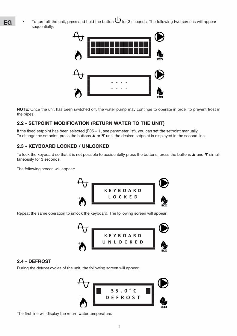
EG • Toturnofftheunit,pressandholdthebutton for3seconds.Thefollowingtwoscreenswillappear sequentially:
- - - -- - - -
2.2 - setPoint moDifiCation (retUrn Water to tHe Unit)
Ifthefixedsetpointhasbeenselected(P05=1,seeparameterlist),youcansetthesetpointmanually.Tochangethesetpoint,pressthebuttonss or tuntilthedesiredsetpointisdisplayedinthesecondline.
2.3 - KeYBoarD loCKeD / UnloCKeD
Tolockthekeyboardsothatitisnotpossibletoaccidentallypressthebuttons,pressthebuttonssandtsimul-taneouslyfor3seconds.
Thefollowingscreenwillappear:
K E Y B O A R DL O C K E D
K E Y B O A R DU N L O C K E D
Repeatthesameoperationtounlockthekeyboard.Thefollowingscreenwillappear:
note:Oncetheunithasbeenswitchedoff,thewaterpumpmaycontinuetooperateinordertopreventfrostinthe pipes.
2.4 - DefrostDuringthedefrostcyclesoftheunit,thefollowingscreenwillappear:
3 5 . 0 ° CD E F R O S T
Thefirstlinewilldisplaythereturnwatertemperature.
5
EG
5
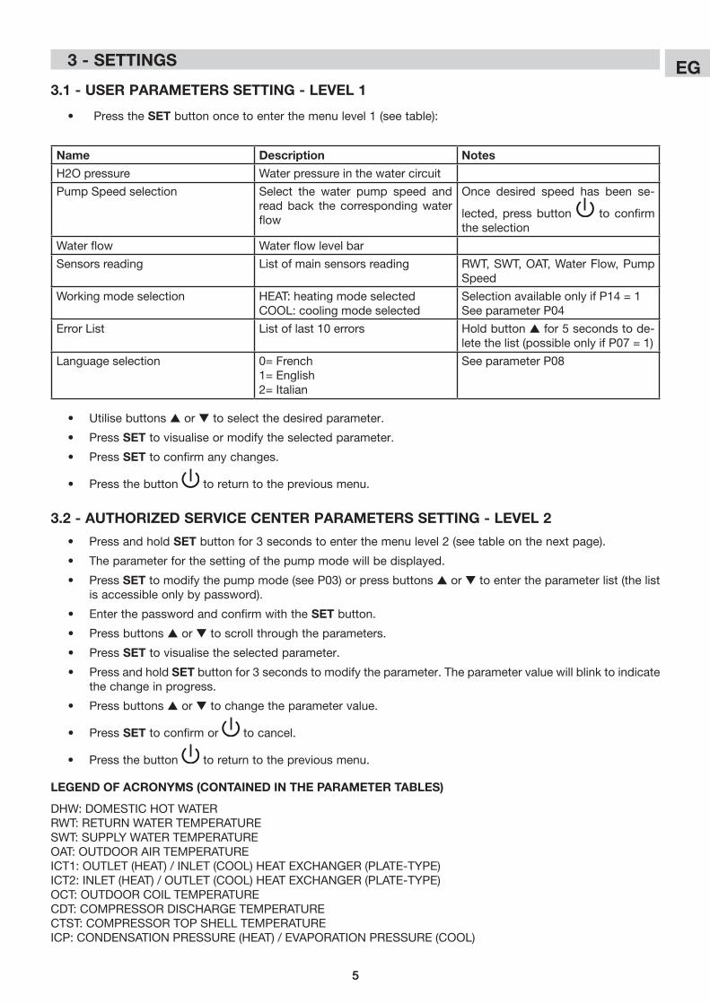
3.2 - aUtHorizeD serviCe Center Parameters settinG - level 2
• Pressandholdsetbuttonfor3secondstoenterthemenulevel2(seetableonthenextpage).
• Theparameterforthesettingofthepumpmodewillbedisplayed.
• Press settomodifythepumpmode(seeP03)orpressbuttonss or t toentertheparameterlist(thelistisaccessibleonlybypassword).
• Enterthepasswordandconfirmwiththeset button.
• Pressbuttonss or t toscrollthroughtheparameters.
• Press settovisualisetheselectedparameter.
• Pressandholdsetbuttonfor3secondstomodifytheparameter.Theparametervaluewillblinktoindicatethe change in progress.
• Pressbuttonss or t tochangetheparametervalue.
• Press set to confirm or to cancel.
• Pressthebutton toreturntothepreviousmenu.
3.1 - User Parameters settinG - level 1
• Pressthesetbuttononcetoenterthemenulevel1(seetable):
• Utilisebuttonss or t toselectthedesiredparameter.
• Press settovisualiseormodifytheselectedparameter.
• Press settoconfirmanychanges.
• Pressthebutton toreturntothepreviousmenu.
name Description notes
H2Opressure Waterpressureinthewatercircuit
PumpSpeedselection Select the water pump speed andreadback thecorrespondingwaterflow
Once desired speed has been se-
lected,pressbutton to confirm the selection
Waterflow Waterflowlevelbar
Sensorsreading Listofmainsensorsreading RWT,SWT,OAT,WaterFlow,PumpSpeed
Workingmodeselection HEAT:heatingmodeselectedCOOL:coolingmodeselected
SelectionavailableonlyifP14=1See parameter P04
Error List List of last 10 errors Holdbuttonsfor5secondstode-letethelist(possibleonlyifP07=1)
Languageselection 0=French1=English2=Italian
See parameter P08
leGenD of aCronYms (ContaineD in tHe Parameter taBles)
DHW: DOMESTIC HOT WATERRWT: RETURN WATER TEMPERATURESWT: SUPPLY WATER TEMPERATUREOAT: OUTDOOR AIR TEMPERATUREICT1:OUTLET(HEAT)/INLET(COOL)HEATEXCHANGER(PLATE-TYPE)ICT2:INLET(HEAT)/OUTLET(COOL)HEATEXCHANGER(PLATE-TYPE)OCT: OUTDOOR COIL TEMPERATURECDT: COMPRESSOR DISCHARGE TEMPERATURECTST: COMPRESSOR TOP SHELL TEMPERATUREICP:CONDENSATIONPRESSURE(HEAT)/EVAPORATIONPRESSURE(COOL)
3 - settinGs
6
EG
6
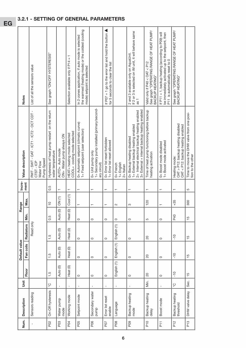
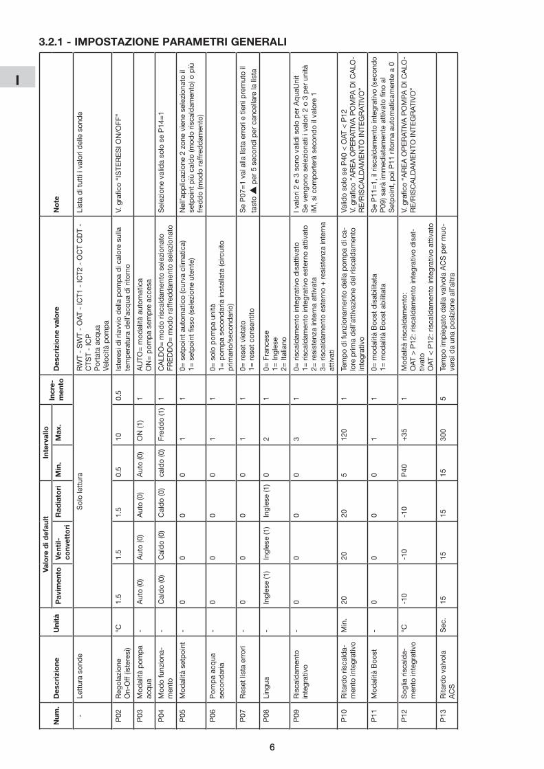
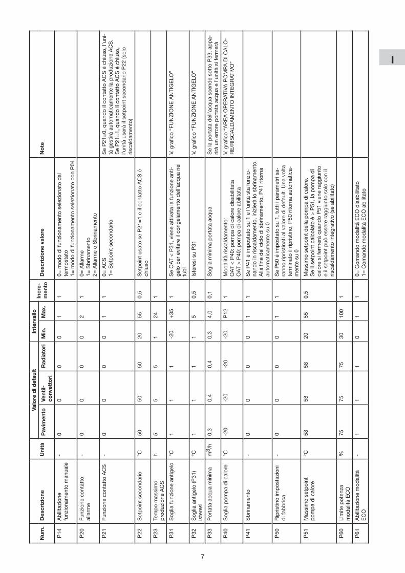
3.2.1 - settinG of General Parametersn
um.
Des
crip
tio
nU
nit
Def
ault
val
uer
ang
ein
cre-
men
tva
lue
des
crip
tio
nn
ote
sfl
oo
rfa
n co
ilsr
adia
tors
min
.m
ax.
-Sen
sorsrea
ding
Rea
donly
RW
T -
SW
T -
OAT
- IC
T1 -
ICT2
- O
CT
CD
T -
CTS
T -
ICP
WaterFlow
Pum
pSpee
d
Listofa
llthese
nsorsva
lue
P02
On-Offhy
steres
is°C
1.5
1.5
1.5
0.5
100.
5Hysteresisofhea
tpum
pres
tarto
nthereturn
watertem
perature
See
gra
ph
“ON
/OFF
HY
STE
RE
SIS
”
P03
Waterpum
p
mod
e-
Auto(0)
Auto(0)
Auto(0)
Auto(0)
ON(1
)1
AUTO
=A
utomod
eON=W
aterpum
palway
sON
P04
Working
mod
e-
Hea
t(0)
Hea
t(0)
Hea
t(0)
Hea
t(0)
Coo
l(1)
1HEAT
=hea
tingmod
ese
lected
COOL=
coo
lingmod
ese
lected
Selec
tionav
ailableonlyifP14
=1
P05
Setpointm
ode
-0
00
01
10=
Autom
aticsetpoint(c
limaticcurve
)1=
Fixed
setpoint(u
serse
lection)
In2-zon
esapplication,ifautomod
eisselec
ted
thewarmes
t(hea
tingmod
e)ortheco
ldes
t(coo
ling
mod
e)setpointisselec
ted
P06
Sec
ondarywater
pum
p-
00
00
11
0=Unitpum
ponly
1=Sec
ondarypum
pin
stalled(p
rimary/se
cond
-arycircuit)
P07
Err
or li
st r
eset
en
able
-0
00
01
10=
Errorlistres
etfo
rbidden
1=Errorlistres
etallo
wed
IfP07
=1gotothe
errorlistand
holdthe
button
s
for5se
cond
stoclearthe
list
P08
Lang
uage
-Eng
lish(1)
Eng
lish(1)
Eng
lish(1)
02
10=
Frenc
h1=
Eng
lish
2=Italian
P09
Bac
kuphea
ting
mod
e-
00
00
31
0=Bac
kuphea
tingdisab
led
1=Externa
lbac
kuphea
tingen
abled
2=Interna
lelectric
albac
kuphea
tingen
abled
3=Externa
l+in
ternalbac
kuphea
tingen
abled
2an
d3ava
ilableonlyon
Aqua
Unit.
If2or3isselec
tedoniM
unit,itw
illbeh
avesa
me
as 1
P10
Bac
kuphea
ting
delay
Min
.20
2020
512
01
Timeofhea
tpum
pfu
nctio
ning
beforebac
kup
heatingac
tivation
Valid
onlyifP40
<O
AT<P12
See
gra
ph
“OP
ER
ATIN
G R
AN
GE
OF
HE
AT P
UM
P/
BA
CK
UP
HE
ATIN
G”
P11
Boo
stm
ode
-0
00
01
10=
Boo
stm
odedisab
led
1=Boo
stm
odeac
tivated
IfP11
=1,b
acku
phea
ting(acc
ordingtoP09
)will
beim
med
iatelyactivated
uptothese
tpoint,the
nP11
isau
tomaticallyres
etto0
P12
Bac
kuphea
ting
thresh
old
°C-1
0-1
0-1
0P
40+35
1Hea
tingmod
e:OAT
>P12
:bac
kuphea
tingdisab
led
OAT
<P12
:bac
kuphea
tingen
abled
See
gra
ph
“OP
ER
ATIN
G R
AN
GE
OF
HE
AT P
UM
P/
BA
CK
UP
HE
ATIN
G”
P13
DHWvalve
delay
Sec
.15
1515
1530
05
Timetom
ovetheDHWvalve
from
one
pos
i-tio
n to
the
oth
er
7
EG
7
num
.D
escr
ipti
on
Uni
tD
efau
lt v
alue
inte
rval
loin
cre-
men
tva
lue
des
crip
tio
nn
ote
sfl
oo
rfa
n co
ilsr
adia
tors
min
.m
ax.
P14
Working
mod
ese
lect
ion
-0
00
01
10=
Working
mod
ese
lected
bythermos
tat
1=W
orking
mod
ese
lected
with
P04
P20
Ala
rm c
onta
ct
func
tion
-0
00
02
10=
Alarm
1=Defrost
2=Alarm
ordefrost
P21
DH
W c
onta
ct
func
tion
-0
00
01
10=
DHW
1=S
econ
daryse
tpoint
IfP21
=0,w
henDHWcon
tactisclose
dthe
unitwillautom
ati-
callym
anag
etheDHWproduc
tion.
IfP21
=1,w
henDHWcon
tactisclose
dthe
unitwilluse
the
se
cond
aryse
tpointP22
(hea
tingon
ly).
P22
Sec
ondary
setp
oint
°C50
5050
2055
0,5
Setpointuse
difP21
=1and
DHWcon
tactis
clos
ed
P23
Max
imum
DHW
produc
tiontim
eh
55
51
241
P31
Antifree
zefu
nc-
tionthresh
old
°C1
11
-20
+35
1IfOAT
<P31
,antifree
zefu
nctio
nisactivated
in
ordertoav
oidw
aterfree
zing
inthe
pipings
.S
ee g
rap
h “A
NTI
FRE
EZ
E F
UN
CTI
ON
”
P32
Ant
ifree
ze
thresh
old(P
31)
hysteres
is
°C1
11
15
0,5
HysteresisonP31
See
gra
ph
“AN
TIFR
EE
ZE
FU
NC
TIO
N”
P33
Minim
umw
ater
flow
m3 /
h0,3
0,4
0,4
0,3
4,0
0,1
Minim
umw
aterflow
thres
hold
Ifwaterflow
dropsbelow
P33
,waterflow
errorw
illappea
ran
d
theun
itwillstop
P40
Hea
tpum
p
thresh
old
°C-2
0-2
0-2
0-2
0P
121
Hea
tingmod
e:OAT
<P40
:hea
tpum
pdisab
led
OAT
>P40
:hea
tpum
pena
bled
See
gra
ph
“OP
ER
ATIN
G R
AN
GE
OF
HE
AT P
UM
P/B
AC
KU
P
HE
ATIN
G”
P41
Def
rost
-0
00
01
1IfP41
issetto1an
dunitisrun
ning
inhea
ting
mod
e,adefrostw
illstart.A
ttheen
dofd
efrost
cycleP41
isautom
aticallyres
etto0
P50
Factorydefau
ltre
set
-0
00
01
1IfP50
issetto1,allparam
eterswillberese
tto
thedefau
ltva
lue.Afterthe
res
ethas
bee
ndon
e,
P50
isautom
aticallyres
etto0
P51
Max
imum
hea
tpum
psetpoint
°C58
5858
2055
0,5
Max
imum
setpointfo
rthehe
atpum
p.
Ifca
lculated
setpointis>P51
,hea
tpum
pw
ill
stop
whe
nP51
isrea
ched
and
setpointcan
only
bereac
hedw
ithbac
kuphea
ting(ifena
bled).
P60
Eco
mod
epow
er
limit
%75
7575
3010
01
P61
Eco
mod
een
able
-1
11
01
10=
Eco
mod
eco
mman
ddisab
led
1=Eco
mod
eco
mman
dena
bled
8
EG
8
num
.D
escr
ipti
on
Uni
tD
efau
lt v
alue
ran
ge
incr
e-m
ent
valu
e d
escr
ipti
on
no
tes
flo
or
fan
coils
rad
iato
rsm
in.
max
.
P10
1Planttyp
e(singlezo
neorzo
ne1)
-0
12
02
10=
Und
erflo
or1=
Fan
coil
2=Low
tem
peratureradiators
Whe
nP10
1ischa
nged
,P10
5/P10
6/P12
0/P12
1P12
3arerese
ttothe
corresp
ondingdefau
ltva
lue.
P10
5Max
imum
clim
atic
curvese
tpoint
(singlezo
neorzo
ne1)
°C35
4550
3055
0,5
Onlyforhe
atingmod
eS
ee g
rap
h “C
LIM
ATIC
CU
RV
E”
P10
6Minim
umclim
atic
curvese
tpoint
(singlezo
neorzo
ne1)
°C20
3540
2040
0,5
See
gra
ph
“CLI
MAT
IC C
UR
VE
”
P12
0Temperatureformax
i-mum
setpoint
(singlezo
neorzo
ne1)
°C-7
-7-7
-20
P12
10,5
Settotheminim
umexp
ectedreg
iona
ltem
perature
See
gra
ph
“CLI
MAT
IC C
UR
VE
”
P12
1Temperatureformini-
mum
setpoint
(singlezo
neorzo
ne1)
°C17
1717
P12
0+35
0,5
IfP12
1<P12
0,P12
0isautom
aticallysettoP12
1S
ee g
rap
h “C
LIM
ATIC
CU
RV
E”
P12
3C
oolin
g se
tpoi
nt(singlezo
neorzo
ne1)
°C23
12-
1030
0,5
Incoo
lingmod
ethese
tpointisfixe
dand
itcorresp
onds
to P
123
P13
0Calcu
latedsetpoint
(singlezo
neorzo
ne1)
°CRea
donly
P13
1Lo
wes
tco
oling
setpointw
ith0-10V
co
ntro
l(singlezo
neorzo
ne1)
°C23
12-
10P
132
0,5
Activeon
lyifP15
0=1,itco
rres
pon
dstoasigna
lof1
0VS
ee g
rap
h “0
-10V
CO
NTR
OL”
P13
2H
ighe
st c
oolin
g se
tpointw
ith0-10V
co
ntro
l(singlezo
neorzo
ne1)
°C30
30-
P13
130
0,5
Activeon
lyifP15
0=1,itco
rres
pon
dstoasigna
lof0
V.IfP13
2<P13
1,P13
2isautom
aticallysettoP13
1S
ee g
rap
h “0
-10V
CO
NTR
OL”
P15
00-10
Vsigna
lfun
ction
(singlezo
neorzo
ne1)
-0
00
04
10=
Disab
led
1=The
rmallo
ad2=
Setpointcom
man
d3=
The
rmallo
adonou
tdoo
run
it4=
Setpointcom
man
donou
tdoo
run
it
IfP15
0=3or4,0-10V
signa
lisread
onou
tdoo
run
iton
lyand
signa
lsonzo
ne1and
2w
illbeigno
red
See
gra
ph
“0-1
0V C
ON
TRO
L”
P15
1Max
imum
0-10V
se
tpoi
nt s
hift
°C5
55
110
0,5
Activeon
lyin
hea
tingmod
ean
difP15
0=1.
Itreprese
ntsthesh
iftonthese
tpointw
ithasigna
lof
10V.(S
eegraph“0-10V
CONTR
OL”)
P15
2Man
ualsetpointshift
°C0
00
010
0,5
Clim
aticcurve
man
ualsetpointshiftin
hea
tingmod
e
P16
0Mixingva
lvedelay
sec
6060
6030
300
5
P16
1Mixingva
lveco
ntrol
type
-0
00
01
10=230
Vac
con
trol(2
or3points)
1=0-10V
con
trol
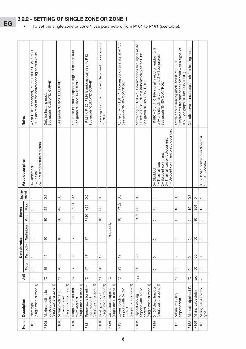
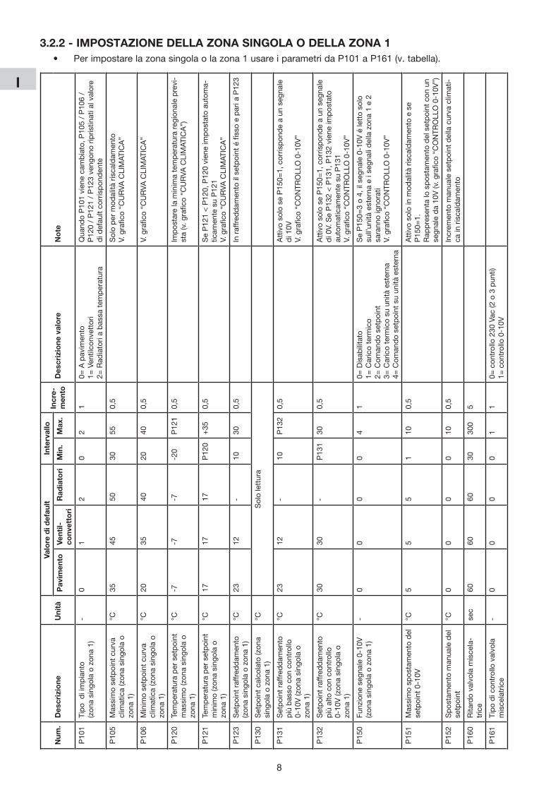
• Tosetthesinglezoneorzone1useparametersfromP101toP161(seetable).
3.2.2 - settinG of sinGle zone or zone 1
9
EG
9
num
.D
escr
ipti
on
Uni
tD
efau
lt v
alue
ran
ge
incr
e-m
ent
valu
e d
escr
ipti
on
no
tes
flo
or
fan
coils
rad
iato
rsm
in.
max
.
P20
1Planttyp
e(zon
e2)
-0
12
02
10=Und
erflo
or
1=Fan
coil
2=Low
tem
peratureradiators
Whe
nP20
1ischa
nged
,P20
5/P20
6/P22
0/P22
1P22
3arerese
ttothe
corresp
ondingdefau
ltva
lue.
P20
5Max
imum
clim
aticcurve
se
tpoint(z
one2)
°C35
4550
3055
0,5
Onlyforhe
atingmod
eS
ee g
rap
h “C
LIM
ATIC
CU
RV
E”
P20
6Minim
umclim
aticcurve
se
tpoint(z
one2)
°C20
3540
2040
0,5
See
gra
ph
“CLI
MAT
IC C
UR
VE
”
P22
0Temperatureformax
imum
se
tpoint(z
one2)
°C-7
-7-7
-20
P22
10,5
Settotheminim
umexp
ectedreg
iona
ltem
perature
See
gra
ph
“CLI
MAT
IC C
UR
VE
”
P22
1Temperatureforminim
um
setpoint(z
one2)
°C17
1717
P22
0+35
0,5
IfP22
1<P22
0,P22
0isautom
aticallysettoP22
1S
ee g
rap
h “C
LIM
ATIC
CU
RV
E”
P22
3C
oolin
g se
tpoi
nt(zon
e2)
°C23
12-
1030
0,5
Incoo
lingmod
ethese
tpointisfixe
dand
itcorresp
onds
to P
223
P23
0Calcu
latedsetpoint
(zon
e2)
°C-
--
Rea
donly
P23
1Lo
wes
tco
olingse
tpoint
with
0-10V
con
trol
(zon
e2)
°C23
12-
10P
232
0,5
Activeon
lyifP25
0=1,itco
rres
pon
dstoasigna
lof1
0V.
See
gra
ph
“0-1
0V C
ON
TRO
L”
P23
2H
ighe
st c
oolin
g se
tpoi
nt
with
0-10V
con
trol
(zon
e2)
°C30
30-
P23
130
0,5
Activeon
lyifP25
0=1,itco
rres
pon
dstoasigna
lof0
V.IfP23
2<P23
1,P23
2isautom
aticallysettoP23
1S
ee g
rap
h “0
-10V
CO
NTR
OL”
P25
00-10
Vsigna
lfun
ction
(zon
e2)
-0
00
02
10=Disab
led
1=The
rmallo
ad
2=Setpointcom
man
d
IfP25
0=3or4,0-10V
signa
lisread
onou
tdoo
run
iton
lyand
signa
lsonzo
ne1and
2w
illbeigno
red.
See
gra
ph
“0-1
0V C
ON
TRO
L”
P25
1Max
imum
0-10V
setpoint
shift
°C5
55
110
0,5
Activeon
lyin
hea
tingmod
ean
difP25
0=1.
Itreprese
ntsthesh
iftonthese
tpointw
ithasigna
lof
10V.(S
eegraph“0-10V
CONTR
OL”)
P25
2Man
ualsetpointshift
°C0
00
010
0,5
Clim
aticcurve
man
ualsetpointshiftin
hea
tingmod
e
P26
0Mixingva
lvedelay
sec
6060
6030
300
5
P26
1Mixingva
lveco
ntroltyp
e-
00
00
11
0=230
Vac
con
trol(2
or3points)
1=0-10V
con
trol
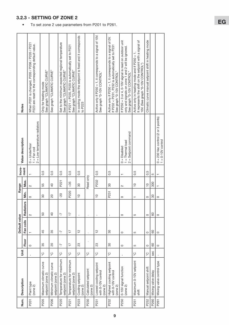
• Tosetzone2useparametersfromP201toP261.
3.2.3 - settinG of zone 2
10
EG 4 - GraPHs
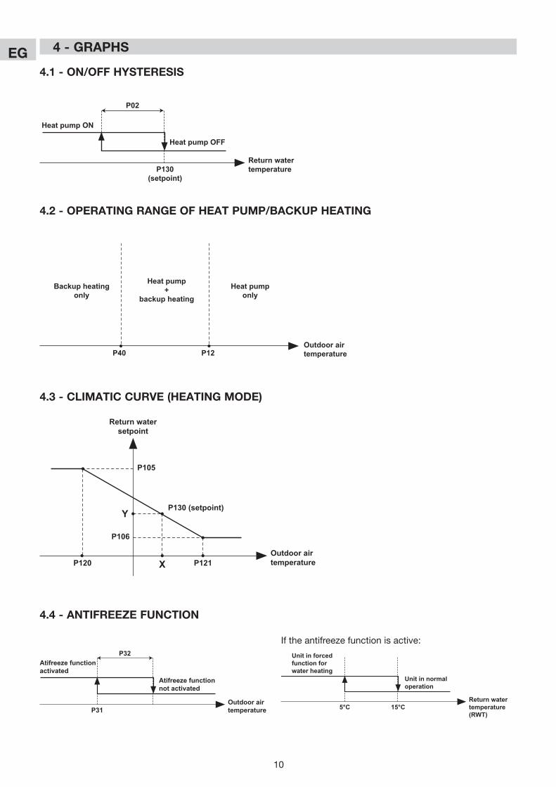
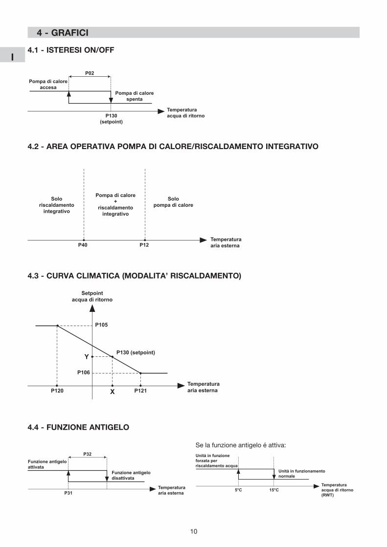
4.1 - on/off HYsteresis
Return watertemperatureP130
(setpoint)
Heat pump ON
Heat pump OFF
P02
4.2 - oPeratinG ranGe of Heat PUmP/BaCKUP HeatinG
P40 P12Outdoor airtemperature
Heat pump+
backup heatingHeat pump
onlyBackup heating
only
4.3 - ClimatiC CUrve (HeatinG moDe)
X
Y
P105
P106
P120 P121
P130 (setpoint)
Outdoor airtemperature
Return watersetpoint
4.4 - antifreeze fUnCtion
Outdoor airtemperatureP31
Atifreeze functionactivated
Atifreeze functionnot activated
P32
Iftheantifreezefunctionisactive:
Return watertemperature(RWT)
5°C
Unit in forced function for water heating
Unit in normal operation
15°C
11
EG
X
Y
P105
P106
P120 P121
P130 (setpoint)
Outdoor airtemperature
Return watersetpoint
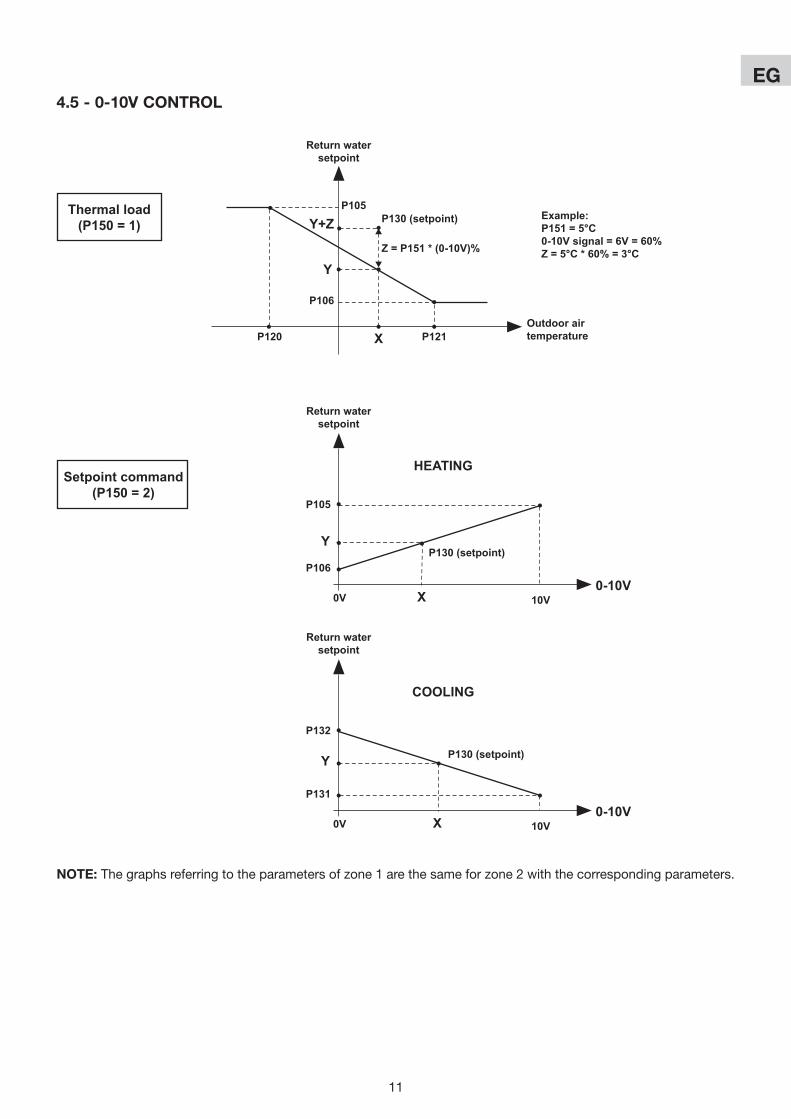
Thermal load(P150 = 1) Y+Z
Z = P151 * (0-10V)%
Example:P151 = 5°C0-10V signal = 6V = 60%Z = 5°C * 60% = 3°C
P105
P106
Return watersetpoint
Setpoint command(P150 = 2)
0-10V0V 10V
P130 (setpoint)
X
Y
HEATING
P132
P131
Return watersetpoint
0-10V0V 10V
P130 (setpoint)
X
Y
COOLING
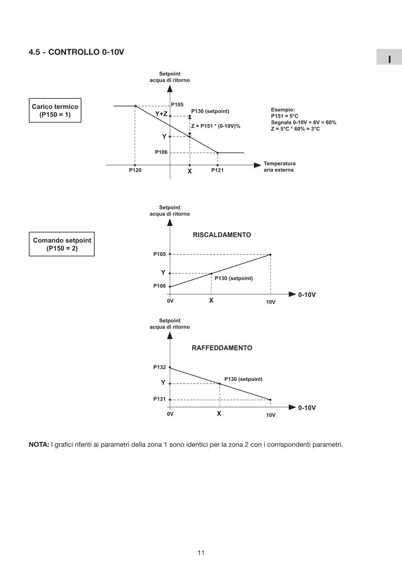
4.5 - 0-10v Control
note: Thegraphsreferringtotheparametersofzone1arethesameforzone2withthecorrespondingparameters.
2
I
2
1 - Presentazione degli elementi della regolazione ...................................................................... 2 2 - Funzionamento ........................................................................................................................ 3 3 - Impostazioni ............................................................................................................................ 5 4 - Grafici .................................................................................................................................... 10
INDICE
1 - PrEsENtazIoNE DEglI ElEmENtI DElla rEgolazIoNE
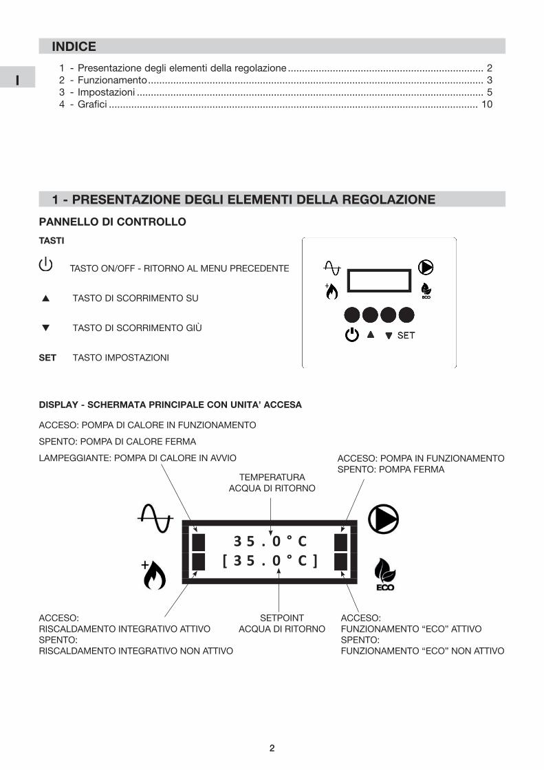
PaNNEllo DI CoNtrollo
tastI
TASTO ON/OFF - RITORNO AL MENU PRECEDENTE
s TASTO DI SCORRIMENTO SU
t TASTO DI SCORRIMENTO GIÙ
sEt TASTO IMPOSTAZIONI
3 5 . 0 ° C[ 3 5 . 0 ° C ]
ACCESO: POMPA DI CALORE IN FUNZIONAMENTO
SPENTO: POMPA DI CALORE FERMA
LAMPEGGIANTE: POMPA DI CALORE IN AVVIO ACCESO: POMPA IN FUNZIONAMENTOSPENTO: POMPA FERMA
ACCESO: RISCALDAMENTO INTEGRATIVO ATTIVOSPENTO:RISCALDAMENTO INTEGRATIVO NON ATTIVO
ACCESO: FUNZIONAMENTO “ECO” ATTIVOSPENTO:FUNZIONAMENTO “ECO” NON ATTIVO
TEMPERATURA ACQUA DI RITORNO
SETPOINTACQUA DI RITORNO
DIsPlaY - sCHErmata PrINCIPalE CoN UNIta’ aCCEsa
3
I
3
2 - FUNzIoNamENto
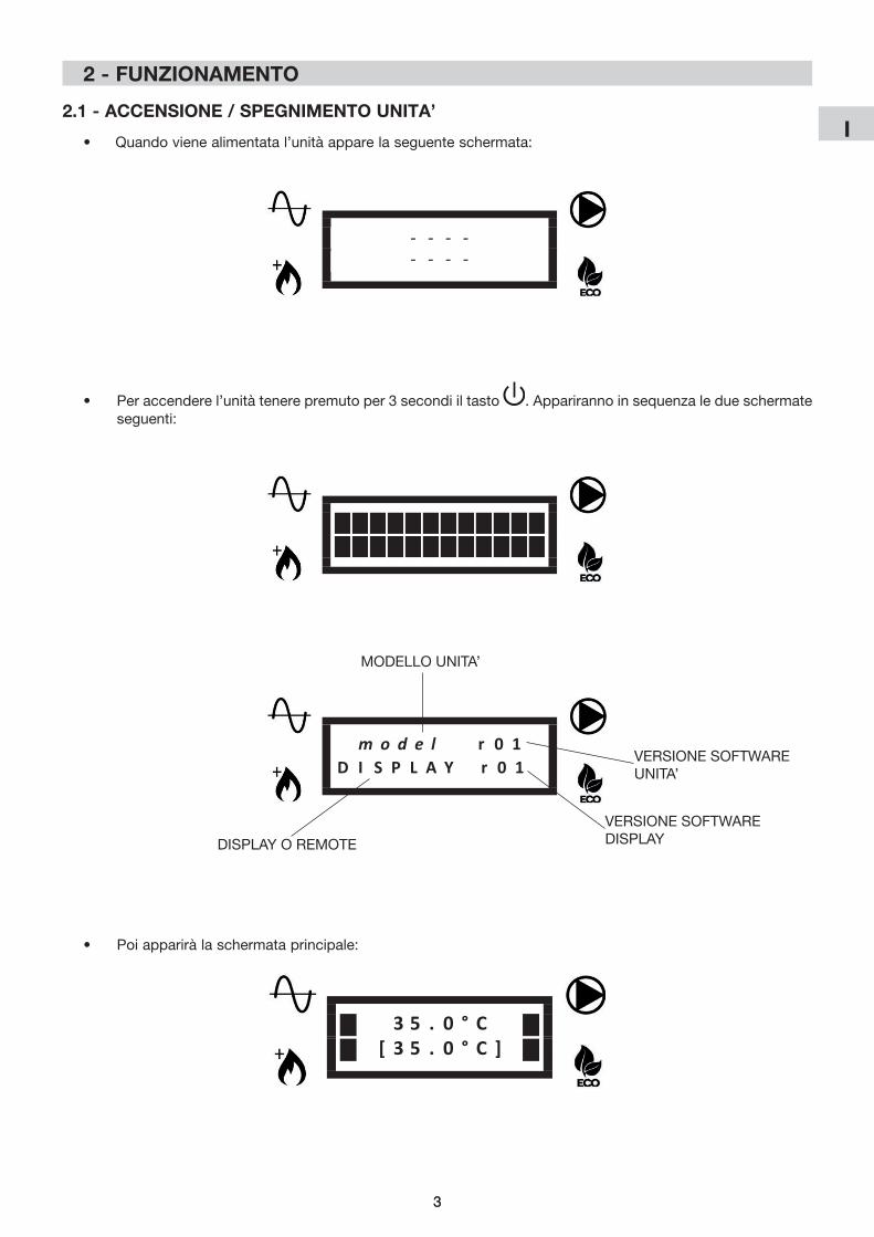
2.1 - aCCENsIoNE / sPEgNImENto UNIta’
• Peraccenderel’unitàtenerepremutoper3secondiiltasto . Appariranno in sequenza le due schermate seguenti:
- - - -- - - -
• Quandovienealimentatal’unitàapparelaseguenteschermata:
m o d e l r 0 1D I S P L A Y r 0 1
MODELLOUNITA’
VERSIONE SOFTWARE UNITA’
VERSIONE SOFTWARE DISPLAY
• Poiappariràlaschermataprincipale:
3 5 . 0 ° C[ 3 5 . 0 ° C ]
DISPLAY O REMOTE
4
I
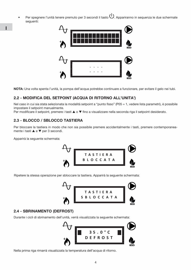
• Perspegnerel’unitàtenerepremutoper3secondiiltasto . Appariranno in sequenza le due schermate seguenti:
- - - -- - - -
2.2 - moDIFICa DEl sEtPoINt (aCQUa DI rItorNo all’UNIta’)
Nelcasoincuisiastataselezionatalamodalitàsetpointa“puntofisso”(P05=1,vederelistaparametri),èpossibileimpostare il setpoint manualmente.Permodificareilsetpoint,premereitastis o tfinoavisualizzarenellasecondarigailsetpointdesiderato.
2.3 - BloCCo / sBloCCo tastIEra
Perbloccarelatastierainmodochenonsiapossibilepremereaccidentalmenteitasti,premerecontemporanea-mente i tasti s e t per 3 secondi.
Appariràlaseguenteschermata:
T A S T I E R AB L O C C A T A
T A S T I E R AS B L O C C A T A
Ripeterelastessaoperazionepersbloccarelatastiera.Appariràlaseguenteschermata:
Nota:Unavoltaspental’unità,lapompadell’acquapotrebbecontinuareafunzionare,perevitareilgeloneitubi.
2.4 - sBrINamENto (DEFrost)
Duranteiciclidisbrinamentodell’unità,verràvisualizzatalaseguenteschermata:
3 5 . 0 ° CD E F R O S T
Nellaprimarigarimarràvisualizzatalatemperaturadell’acquadiritorno.
5
I
5
3.2 - ImPostazIoNE ParamEtrI CENtro assIstENza aUtorIzzato - lIVEllo 2
• Tenere premuto il tasto sEtper3secondiperentrarenelmenùlivello2(v.tabellapag.successiva).
• Verràvisualizzatoilparametroperl’impostazionedellamodalitàdellapompa.
• Premere sEtpermodificarelamodalitàdellapompa(v.P03)oppurepremereitastis o t per accedere allalistaparametri(lalistaèaccessibilesolotramitepassword).
• ImmetterelapasswordeconfermareconiltastosEt.
• Premere i tasti s o t per scorrere i parametri.
• Premere sEtpervisualizzareilparametroselezionato.
• Tenere premuto sEtper3 secondipermodificare il parametro. Il valoredelparametro lampeggeràperindicare la modifica in corso.
• Premere i tasti s o t percambiareilvaloredelparametro.
• Premere sEt per confermare o per annullare.
• Utilizzare il tasto per tornare al menù precedente.
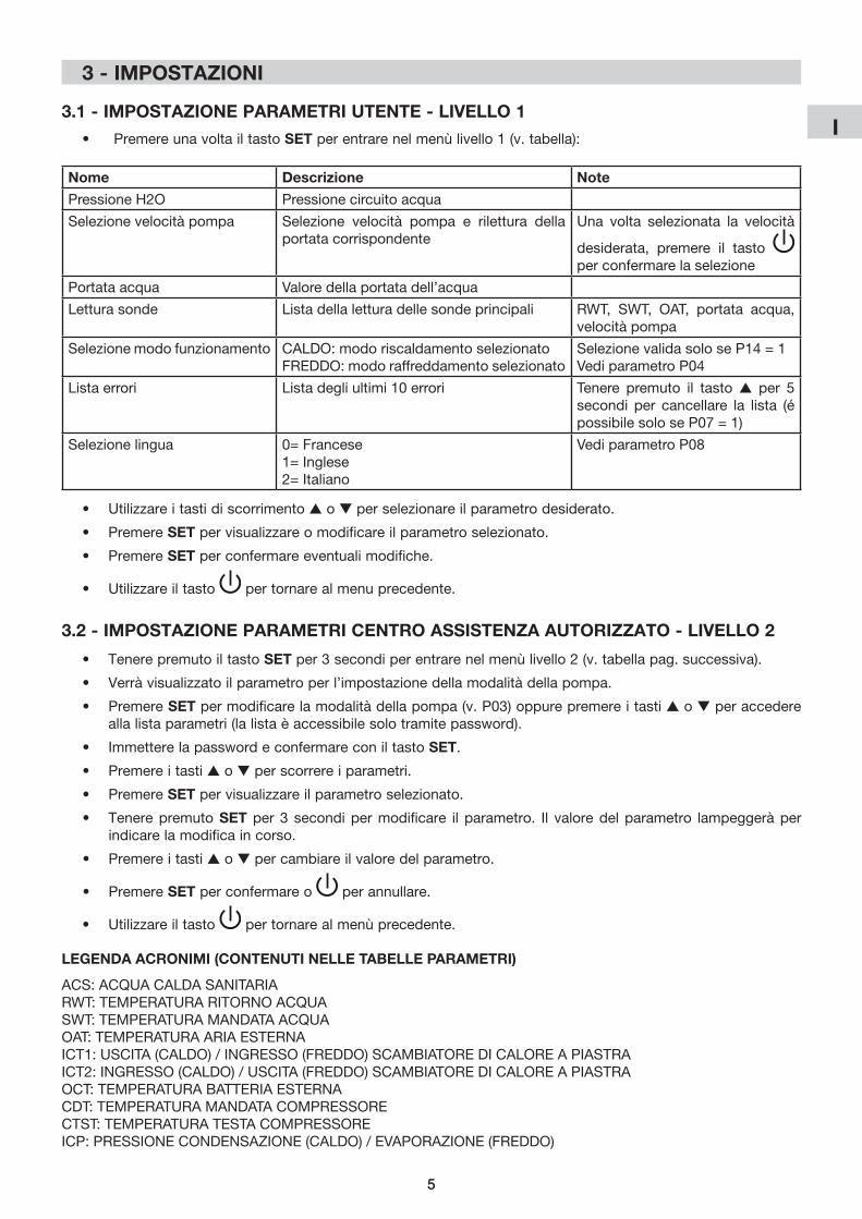
3.1 - ImPostazIoNE ParamEtrI UtENtE - lIVEllo 1
• PremereunavoltailtastosEtperentrarenelmenùlivello1(v.tabella):
Nome Descrizione Note
Pressione H2O Pressione circuito acqua
Selezionevelocitàpompa Selezione velocità pompa e rilettura dellaportata corrispondente
Una volta selezionata la velocità
desiderata, premere il tasto per confermare la selezione
Portata acqua Valoredellaportatadell’acqua
Lettura sonde Lista della lettura delle sonde principali RWT, SWT, OAT, portata acqua,velocitàpompa
Selezione modo funzionamento CALDO: modo riscaldamento selezionatoFREDDO: modo raffreddamento selezionato
SelezionevalidasoloseP14=1Vedi parametro P04
Lista errori Lista degli ultimi 10 errori Tenere premuto il tasto s per 5 secondi per cancellare la lista (épossibilesoloseP07=1)
Selezione lingua 0=Francese1=Inglese2=Italiano
Vedi parametro P08
• Utilizzare i tasti di scorrimento s o t per selezionare il parametro desiderato.
• Premere sEtpervisualizzareomodificareilparametroselezionato.
• Premere sEtperconfermareeventualimodifiche.
• Utilizzare il tasto per tornare al menu precedente.
lEgENDa aCroNImI (CoNtENUtI NEllE taBEllE ParamEtrI)
ACS: ACQUA CALDA SANITARIARWT: TEMPERATURA RITORNO ACQUASWT: TEMPERATURA MANDATA ACQUAOAT: TEMPERATURA ARIA ESTERNAICT1:USCITA(CALDO)/INGRESSO(FREDDO)SCAMBIATOREDICALOREAPIASTRAICT2:INGRESSO(CALDO)/USCITA(FREDDO)SCAMBIATOREDICALOREAPIASTRAOCT:TEMPERATURABATTERIAESTERNACDT: TEMPERATURA MANDATA COMPRESSORECTST: TEMPERATURA TESTA COMPRESSOREICP:PRESSIONECONDENSAZIONE(CALDO)/EVAPORAZIONE(FREDDO)
3 - ImPostazIoNI
6
I
6
Num
.D
escr
izio
neU
nità
Valo
re d
i def
ault
Inte
rval
loIn
cre-
men
toD
escr
izio
ne v
alo
reN
ote
Pav
imen
toVe
ntil-
conv
etto
rir
adia
tori
min
.m
ax.
-Le
ttur
a so
nde
Sol
o le
ttur
aR
WT
- S
WT
- O
AT -
ICT1
- IC
T2 -
OC
T C
DT
- C
TST
- IC
PP
orta
ta a
cqua
Velocitàpom
pa
Listadituttiivalorid
elleson
de
P02
Reg
olaz
ione
On-Off(isteresi)
°C1.
51.
51.
50.
510
0.5
Isteresidiriavviodellapom
padic
aloresu
lla
temperaturadell’a
cqua
dirito
rno
V.grafic
o“ISTE
RESIO
N/O
FF”
P03
Mod
alità
pom
pa
acq
ua-
Auto(0)
Auto(0)
Auto(0)
Auto(0)
ON(1
)1
AUTO
=m
odalità
autom
atica
ON=pom
pase
mpreacc
esa
P04
Mod
o fu
nzio
na-
men
to-
Caldo(0)
Caldo(0)
Caldo(0)
caldo(0)
Fred
do(1)
1CALD
O=m
odoris
caldam
entoselez
iona
toFR
EDDO=m
odoraffred
dam
entoselez
iona
toSelez
ione
validaso
loseP14
=1
P05
Mod
alità
setpoint
-0
00
01
10=
setpointautom
atico(curva
clim
atica)
1=setpointfisso(selez
ione
utente)
Nell’a
pplicaz
ione
2zon
evien
ese
lezion
atoil
setpointpiùcaldo(m
odoris
caldam
ento)o
più
fred
do(m
odoraffred
dam
ento)
P06
Pom
pa
acq
ua
seco
ndar
ia-
00
00
11
0=solopom
paun
ità1=
pom
pase
cond
ariain
stallata(c
ircuito
prim
ario/sec
ondario)
P07
Res
et li
sta
erro
ri-
00
00
11
0=res
etvietato
1=res
etcon
sentito
SeP07
=1va
iallalistaerrorietie
nipremutoil
tast
o s
per
5 s
econ
di p
er c
ance
llare
la li
sta
P08
Ling
ua-
Ingles
e(1)
Ingles
e(1)
Ingles
e(1)
02
10=
Franc
ese
1=In
gles
e2=
Italiano
P09
Ris
cald
amen
to
integrativo
-0
00
03
10=
risca
ldam
entoin
tegrativodisattiv
ato
1=risca
ldam
entoin
tegrativoes
ternoattiv
ato
2=res
istenz
ainternaattiv
ata
3=risca
ldam
entoesterno
+res
istenz
ainterna
attiv
ati
Ivalori2
e3son
ova
lidisoloperAqua
Unit
Seve
ngon
ose
lezion
atiivalori2
o3perunità
iM,s
icom
porteràsec
ondoilva
lore1
P10
Rita
rdo
risca
lda-
men
toin
tegrativo
Min
.20
2020
512
01
Tem
po
di f
unzi
onam
ento
del
la p
omp
a d
i ca-
loreprim
adell’a
ttivaz
ione
delrisca
ldam
ento
integrativo
Valid
o so
lo s
e P
40 <
OAT
< P
12V.grafic
o“A
REAO
PERAT
IVAPOMPA
DIC
ALO
-R
E/R
ISC
ALD
AM
EN
TO IN
TEG
RAT
IVO
”
P11
Mod
alità
Boo
st-
00
00
11
0=m
odalità
Boo
stdisab
ilitata
1=m
odalità
Boo
stabilitata
SeP11
=1,ilrisca
ldam
entoin
tegrativo(sec
ondo
P09
)saràim
med
iatamen
teattivatofin
oal
Setpoint,p
oiP11
rito
rnaau
tomaticam
entea0
P12
Sog
lia r
isca
lda-
men
toin
tegrativo
°C-1
0-1
0-1
0P
40+35
1Mod
alità
risca
ldam
ento:
OAT
>P12
:risca
ldam
entoin
tegrativodisat
-tiv
ato
OAT
<P12
:risca
ldam
entoin
tegrativoattiv
ato
V.grafic
o“A
REAO
PERAT
IVAPOMPA
DIC
ALO
-R
E/R
ISC
ALD
AM
EN
TO IN
TEG
RAT
IVO
”
P13
Rita
rdova
lvola
AC
SS
ec.
1515
1515
300
5Tempoim
piega
todallavalvo
laACSperm
uo-
versid
aun
apos
izione
all’altra
3.2.1 - ImPostazIoNE ParamEtrI gENEralI
7
I
Num
.D
escr
izio
neU
nità
Valo
re d
i def
ault
Inte
rval
loIn
cre-
men
toD
escr
izio
ne v
alo
reN
ote
Pav
imen
toVe
ntil-
conv
etto
rir
adia
tori
min
.m
ax.
P14
Abilitazion
efu
nzio
nam
ento
man
uale
-0
00
01
10=
mod
odifun
zion
amen
toselez
iona
todal
term
osta
to1=
mod
odifun
zion
amen
toselez
iona
tocon
P04
P20
Funz
ione
con
tatt
o al
larm
e-
00
00
21
0=Allarm
e1=
Sbrin
amen
to2=
Allarm
eoSbrin
amen
to
P21
Funz
ione
con
tatt
o A
CS
-0
00
01
10=
ACS
1=Setpointsec
ondario
SeP21
=0,qua
ndoilco
ntattoACSéchius
o,l’un
i-tàges
tiràau
tomaticam
entela
produz
ione
ACS.
SeP21
=1,qua
ndoilco
ntattoACSéchius
o,
l’unitàuse
ràilsetpointsec
ondarioP22
(solo
risca
ldam
ento)
P22
Set
poi
nt s
econ
dar
io°C
5050
5020
550,5
Setpointusa
toseP21
=1eilco
ntattoACSé
chiu
so
P23
Tem
po
mas
sim
o p
rod
uzio
ne A
CS
h5
55
124
1
P31
Sog
lia fu
nzio
ne a
ntig
elo
°C1
11
-20
+35
1SeOAT
<P31
,viene
attivatalafu
nzione
anti-
geloperevitareilcon
gelamen
todell’a
cqua
nei
tubi
V.grafic
o“FUNZIO
NEANTIGELO
”
P32
Sog
liaantigelo(P31
)is
tere
si°C
11
11
50,5
Iste
resi
su
P31
V.grafic
o“FUNZIO
NEANTIGELO
”
P33
Por
tata
acq
ua m
inim
am
3 /h
0,3
0,4
0,4
0,3
4,0
0,1
Sog
lia m
inim
a p
orta
ta a
cqua
Selaportatadell’a
cqua
sce
ndeso
ttoP33
,appa-
riràun
erroreportataacq
uael’un
itàsifermerà
P40
Sog
lia p
omp
a d
i cal
ore
°C-2
0-2
0-2
0-2
0P
121
Mod
alità
risca
ldam
ento:
OAT
<P40
:pom
padic
aloredisab
ilitata
OAT
>P40
:pom
padic
aloreab
ilitata
V.grafic
o“A
REAO
PERAT
IVAPOMPA
DIC
ALO
-R
E/R
ISC
ALD
AM
EN
TO IN
TEG
RAT
IVO
”
P41
Sbrin
amen
to-
00
00
11
SeP41
éim
pos
tatosu1el’u
nitàstafu
nzio
-na
ndoinrisca
ldam
ento,inizieràlosbrin
amen
to.
Allafine
delciclodisbrin
amen
to,P
41rito
rna
auto
mat
icam
ente
su
0
P50
Rip
ristin
o im
pos
tazi
oni
difab
bric
a-
00
00
11
SeP50
éim
pos
tatosu1,tuttiip
aram
etrisa
-rann
orip
ristin
atia
lvaloredid
efau
lt.Una
volta
term
inatoilrip
ristin
o,P50
rito
rnaau
tomatica-
men
te s
u 0
P51
Mas
sim
o se
tpoi
nt
pom
pa
di c
alor
e°C
5858
5820
550,5
Mas
sim
o se
tpoi
nt d
ella
pom
pa
di c
alor
e.Seilse
tpointcalco
latoè>P51
,lapom
padi
caloresifermeràqua
ndoP51
viene
rag
giun
to
e il
setp
oint
può
ess
ere
ragg
iunt
o so
lo c
on il
ris
caldam
entoin
tegrativo(seab
ilitato)
P60
Lim
ite p
oten
za
mod
alità
ECO
%75
7575
3010
01
P61
Abilitazion
emod
alità
E
CO
-1
11
01
10=
Com
andomod
alità
ECOdisab
ilitato
1=Com
andomod
alità
ECOabilitato
8
I
Num
.D
escr
izio
neU
nità
Valo
re d
i def
ault
Inte
rval
loIn
cre-
men
toD
escr
izio
ne v
alo
reN
ote
Pav
imen
toVe
ntil-
conv
etto
rir
adia
tori
min
.m
ax.
P10
1Ti
po
di i
mp
iant
o(zon
asing
olaozo
na1)
-0
12
02
10=
Apav
imen
to1=
Ven
tilco
nvettori
2=Rad
iatoriabas
satem
peratura
Qua
ndoP10
1vien
eca
mbiato,P
105/P10
6/
P12
0/P12
1/P12
3ve
ngon
orip
ristin
atia
lvalore
di d
efau
lt co
rris
pon
den
te
P10
5Mas
simose
tpointcurva
clim
atica(zon
asing
olao
zona
1)
°C35
4550
3055
0,5
Soloperm
odalità
risca
ldam
ento
V.grafic
o“C
URVA
CLIMAT
ICA”
P10
6Minim
ose
tpointcurva
clim
atica(zon
asing
olao
zona
1)
°C20
3540
2040
0,5
V.grafic
o“C
URVA
CLIMAT
ICA”
P12
0Te
mp
erat
ura
per
set
poi
nt
mas
simo(zon
asing
olao
zona
1)
°C-7
-7-7
-20
P12
10,5
Impos
tarela
minim
atemperaturaregion
aleprevi
-sta(v.g
rafic
o“C
URVA
CLIMAT
ICA”)
P12
1Te
mp
erat
ura
per
set
poi
nt
minim
o(zon
asing
olao
zona
1)
°C17
1717
P12
0+35
0,5
SeP12
1<P12
0,P12
0vien
eim
pos
tatoautom
a-tic
amen
te s
u P
121
V.grafic
o“C
URVA
CLIMAT
ICA”
P12
3S
etp
oint
raf
fred
dam
ento
(zon
asing
olaozo
na1)
°C23
12-
1030
0,5
Inraffred
dam
entoilsetpointéfissoeparia
P12
3
P13
0Setpointcalco
lato(z
ona
sing
olaozo
na1)
°CS
olo
lett
ura
P13
1S
etp
oint
raf
fred
dam
ento
piùbas
socon
con
trollo
0-10
V(z
onasing
olao
zona
1)
°C23
12-
10P
132
0,5
Attivoso
loseP15
0=1,corris
pon
deaun
seg
nale
di 1
0VV.grafic
o“C
ONTR
OLL
O0-10V
”
P13
2S
etp
oint
raf
fred
dam
ento
p
iù a
lto c
on c
ontr
ollo
0-10
V(z
onasing
olao
zona
1)
°C30
30-
P13
130
0,5
Attivoso
loseP15
0=1,corris
pon
deaun
seg
nale
di0
V.SeP13
2<P13
1,P13
2vien
eim
pos
tato
auto
mat
icam
ente
su
P13
1 V.grafic
o“C
ONTR
OLL
O0-10V
”
P15
0Fu
nzio
ne s
egna
le 0
-10V
(zon
asing
olaozo
na1)
-0
00
04
10=
Disab
ilitato
1=Caricoterm
ico
2=Com
andose
tpoint
3=Caricoterm
icosu
unitàesterna
4=Com
andose
tpointsuun
itàesterna
SeP15
0=3o4,ilseg
nale0-10V
éle
ttoso
lo
sull’un
itàesterna
eise
gnalid
ellazon
a1e2
sara
nno
igno
rati
V.grafic
o“C
ONTR
OLL
O0-10V
”
P15
1M
assi
mo
spos
tam
ento
del
se
tpoi
nt 0
-10V
°C5
55
110
0,5
Attivoso
loin
mod
alità
risca
ldam
entoese
P15
0=1.
Rap
pre
sent
a lo
sp
osta
men
to d
el s
etp
oint
con
un
segn
aleda10
V(v.g
rafic
o“C
ONTR
OLL
O0-10V
”)
P15
2S
pos
tam
ento
man
uale
del
se
tpoi
nt°C
00
00
100,5
Increm
entom
anua
lesetpointdellacurva
clim
ati-
ca in
ris
cald
amen
to
P16
0Rita
rdova
lvolamisce
la-
tric
ese
c60
6060
3030
05
P16
1Tipodic
ontrollovalvo
la
mis
cela
tric
e-
00
00
11
0=con
trollo230
Vac
(2o3pun
ti)1=
con
trollo0-10V
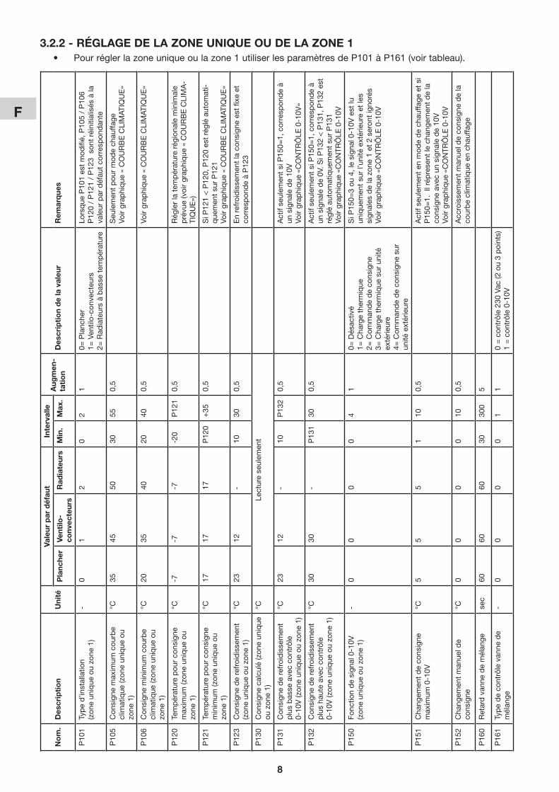
• Perimpostarelazonasingolaolazona1usareiparametridaP101aP161(v.tabella).
3.2.2 - ImPostazIoNE DElla zoNa sINgola o DElla zoNa 1

9
I
Num
.D
escr
izio
neU
nità
Valo
re d
i def
ault
Inte
rval
loIn
cre-
men
toD
escr
izio
ne v
alo
reN
ote
Pav
imen
toVe
ntil-
conv
etto
rir
adia
tori
min
.m
ax.
P20
1Ti
po
di i
mp
iant
o(zon
a2)
-0
12
02
10=Apav
imen
to
1=Ven
tilco
nvettori
2=Rad
iatoriabas
satem
peratura
Qua
ndoP20
1vien
eca
mbiato,P
205/P20
6/P22
0/P22
1P22
3ve
ngon
orip
ristin
atia
lvaloredid
efau
ltco
rrispon
-d
ente
P20
5Mas
simose
tpointcurva
clim
atica(zon
a2)
°C35
4550
3055
0,5
Soloperm
odalità
risca
ldam
ento
V.grafic
o“C
URVA
CLIMAT
ICA”
P20
6Minim
ose
tpointcurva
clim
atica(zon
a2)
°C20
3540
2040
0,5
V.grafic
o“C
URVA
CLIMAT
ICA”
P22
0Te
mp
erat
ura
per
set
poi
nt
mas
simo(zon
a2)
°C-7
-7-7
-20
P22
10,5
Impos
tarela
minim
atemperaturaregion
aleprevista
V.grafic
o“C
URVA
CLIMAT
ICA”
P22
1Te
mp
erat
ura
per
set
poi
nt
minim
o(zon
a2)
°C17
1717
P22
0+35
0,5
SeP22
1<P22
0,P22
0vien
eim
pos
tatoautom
aticam
ente
suP22
1(v.g
rafic
o“C
URVA
CLIMAT
ICA”)
P22
3S
etp
oint
raf
fred
dam
ento
(zon
a2)
°C23
12-
1030
0,5
Inraffred
dam
entoilsetpointéfissoeparia
P22
3
P23
0S
etp
oint
cal
cola
to
(zon
a2)
°C-
--
Sol
o le
ttur
a
P23
1S
etp
oint
raf
fred
dam
ento
piùbas
socon
con
trollo
0-10
V(z
ona2)
°C23
12-
10P
232
0,5
Attivoso
loseP25
0=1,corris
pon
deaun
seg
naledi1
0VV.grafic
o“C
ONTR
OLL
O0-10V
”
P23
2S
etp
oint
raf
fred
dam
ento
p
iù a
lto c
on c
ontr
ollo
0-10
V(z
ona2)
°C30
30-
P23
130
0,5
Attivoso
loseP25
0=1,corris
pon
deaun
seg
naledi0
VSeP23
2<P23
1,P23
2vien
eim
pos
tatoautom
aticam
ente
suP23
1(v.g
rafic
o“C
ONTR
OLL
O0-10V
”)
P25
0Fu
nzio
ne s
egna
le 0
-10V
(zon
a2)
-0
00
02
10=Disab
ilitato
1=Caricoterm
ico
2=Com
andose
tpoint
SeP25
0=3o4,ilseg
nale0-10V
éle
ttoso
losull’u
nità
este
rna
e i s
egna
li d
ella
zon
a 1
e 2
sara
nno
igno
rati
V.grafic
o“C
ONTR
OLL
O0-10V
”
P25
1M
assi
mo
spos
tam
ento
d
el s
etp
oint
0-1
0V°C
55
51
100,5
Attivoso
loin
mod
alità
risca
ldam
entoeseP25
0=1.Rap
-p
rese
nta
lo s
pos
tam
ento
del
set
poi
nt c
on u
n se
gnal
e d
a 10
V(v.g
rafic
o“C
ONTR
OLL
O0-10V
”)
P25
2S
pos
tam
ento
man
uale
d
el s
etp
oint
°C0
00
010
0,5
Increm
entom
anua
lesetpointdellacurva
clim
aticain
risca
ldam
ento
P26
0Rita
rdova
lvola
mis
cela
tric
ese
c60
6060
3030
05
P26
1Tipodic
ontrollovalvo
la
mis
cela
tric
e-
00
00
11
0=con
trollo230
Vac
(2o3pun
ti)
1=con
trollo0-10V
• Perimpostarelazona2usareiparametridaP201aP261.3.2.3 - ImPostazIoNE DElla zoNa 2
10
I
4 - graFICI
4.1 - IstErEsI oN/oFF
Temperatura acqua di ritornoP130
(setpoint)
Pompa di caloreaccesa
P02
Pompa di calorespenta
4.2 - arEa oPEratIVa PomPa DI CalorE/rIsCalDamENto INtEgratIVo
P40 P12Temperaturaaria esterna
Pompa di calore+
riscaldamentointegrativo
Solopompa di calore
Soloriscaldamento
integrativo
4.3 - CUrVa ClImatICa (moDalIta’ rIsCalDamENto)
X
Y
P105
P106
P120 P121
P130 (setpoint)
Temperaturaaria esterna
Setpointacqua di ritorno
4.4 - FUNzIoNE aNtIgElo
Temperaturaaria esternaP31
Funzione antigeloattivata
Funzione antigelodisattivata
P32
Selafunzioneantigeloéattiva:
Temperaturaacqua di ritorno(RWT)
5°C
Unità in funzione forzata per riscaldamento acqua
Unità in funzionamentonormale
15°C
11
I
X
Y
P105
P106
P120 P121
P130 (setpoint)
Temperaturaaria esterna
Setpointacqua di ritorno
Carico termico(P150 = 1) Y+Z
Z = P151 * (0-10V)%
Esempio:P151 = 5°CSegnale 0-10V = 6V = 60%Z = 5°C * 60% = 3°C
P105
P106
Setpointacqua di ritorno
Comando setpoint(P150 = 2)
0-10V0V 10V
P130 (setpoint)
X
Y
RISCALDAMENTO
P132
P131
Setpointacqua di ritorno
0-10V0V 10V
P130 (setpoint)
X
Y
RAFFEDDAMENTO
4.5 - CoNtrollo 0-10V
Nota:Igraficiriferitiaiparametridellazona1sonoidenticiperlazona2conicorrispondentiparametri.
2
F
2
Sommaire 1 - Présentation des éléments de la régulation ............................................................................ 2 2 - Fonctionnement....................................................................................................................... 3 3 - Réglages .................................................................................................................................. 5 4 - Graphiques ............................................................................................................................ 10
1 - PréSentation deS élémentS de la régulation
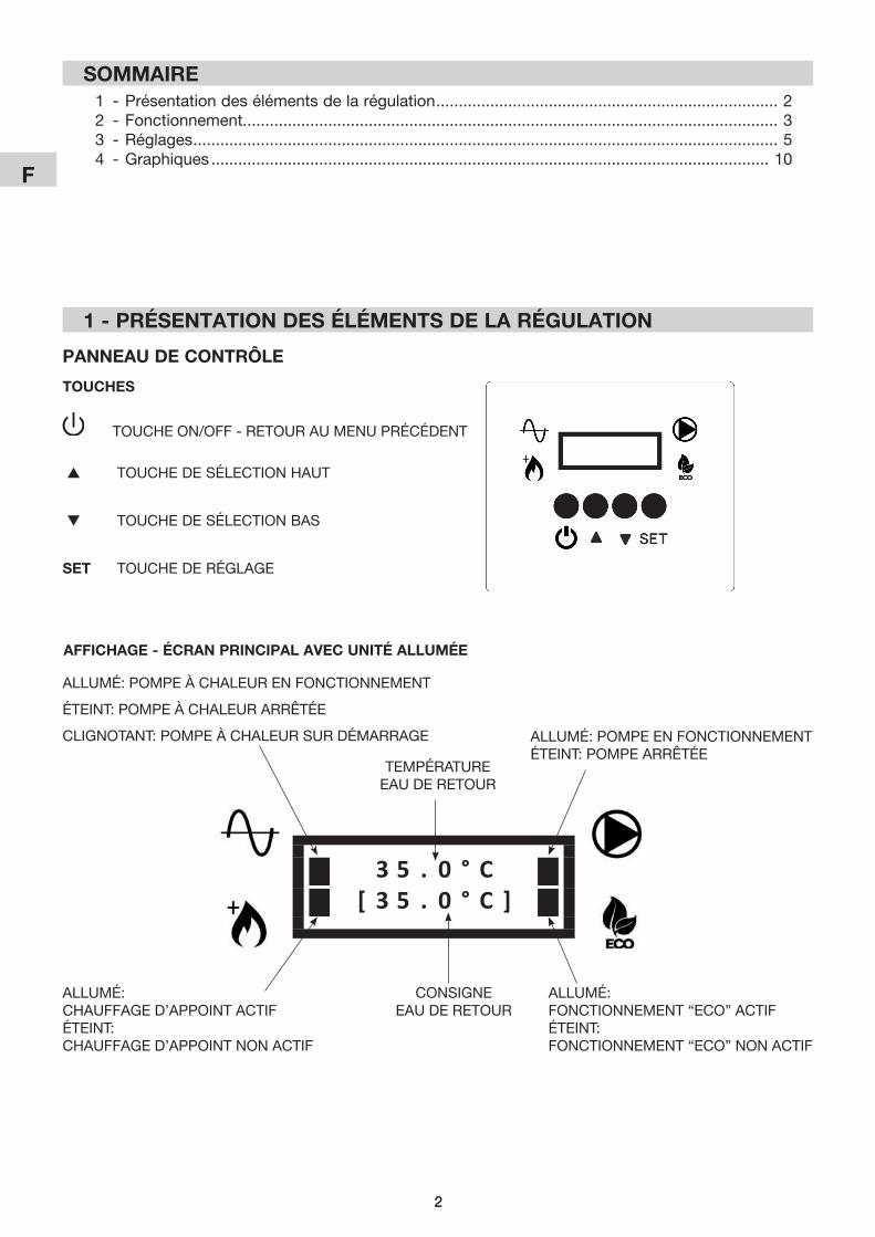
Panneau de ContrÔle
touCHeS
TOUCHE ON/OFF - RETOUR AU MENU PRÉCÉDENT
s TOUCHE DE sÉlECTiON HAUT
t TOUCHE DE sÉlECTiON BAs
Set TOUCHE DE RÉGlAGE
3 5 . 0 ° C[ 3 5 . 0 ° C ]
AllUMÉ: POMPE À CHAlEUR EN FONCTiONNEMENT
ÉTEiNT: POMPE À CHAlEUR ARRÊTÉE
CliGNOTANT: POMPE À CHAlEUR sUR DÉMARRAGE AllUMÉ: POMPE EN FONCTiONNEMENTÉTEiNT: POMPE ARRÊTÉE
AllUMÉ: CHAUFFAGE D’APPOiNT ACTiFÉTEiNT:CHAUFFAGE D’APPOiNT NON ACTiF
AllUMÉ: FONCTiONNEMENT “ECO” ACTiFÉTEiNT:FONCTiONNEMENT “ECO” NON ACTiF
TEMPÉRATURE EAU DE RETOUR
CONsiGNEEAU DE RETOUR
aFFiCHage - éCran PrinCiPal aVeC unité allumée
3
F
3
2 - FonCtionnement
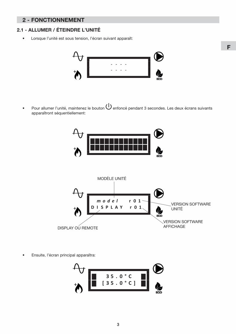
2.1 - allumer / éteindre l’unité
• Pourallumerl’unité,maintenezlebouton enfoncé pendant 3 secondes. les deux écrans suivants apparaîtront séquentiellement:
- - - -- - - -
• Lorsquel’unitéestsoustension,l’écransuivantapparaît:
• Ensuite,l’écranprincipalapparaîtra:
3 5 . 0 ° C[ 3 5 . 0 ° C ]
m o d e l r 0 1D I S P L A Y r 0 1
MODÈlE UNiTÉ
VERsiON sOFTWARE UNiTÉ
VERsiON sOFTWARE AFFiCHAGEDisPlAY OU REMOTE
4
F
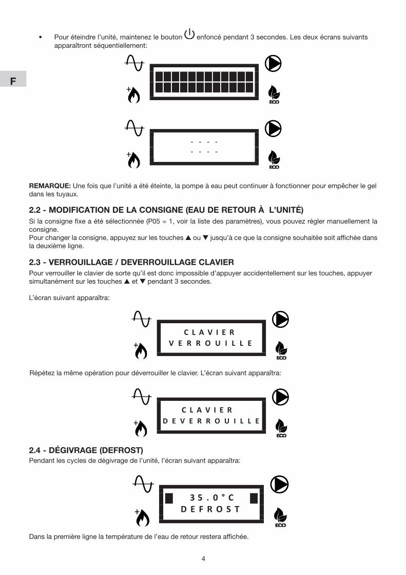
• Pouréteindrel’unité,maintenezlebouton enfoncé pendant 3 secondes. les deux écrans suivants apparaîtront séquentiellement:
- - - -- - - -
2.2 - modiFiCation de la ConSigne (eau de retour À l’unité)Silaconsignefixeaétésélectionnée(P05=1,voirlalistedesparamètres),vouspouvezréglermanuellementlaconsigne.Pourchangerlaconsigne,appuyezsurlestouchess ou t jusqu’à ce que la consigne souhaitée soit affichée dans ladeuxièmeligne.
2.3 - Verrouillage / deVerrouillage ClaVierPourverrouillerleclavierdesortequ’ilestdoncimpossibled’appuyeraccidentellementsurlestouches,appuyersimultanément sur les touches s et t pendant 3 secondes.
l’écran suivant apparaîtra:
C L A V I E RV E R R O U I L L E
C L A V I E RD E V E R R O U I L L E
Répétezlamêmeopérationpourdéverrouillerleclavier.L’écransuivantapparaîtra:
remarQue:Unefoisquel’unitéaétééteinte,lapompeàeaupeutcontinueràfonctionnerpourempêcherlegeldanslestuyaux.
2.4 - dégiVrage (deFroSt)Pendantlescyclesdedégivragedel’unité,l’écransuivantapparaîtra:
3 5 . 0 ° CD E F R O S T
Danslapremièrelignelatempératuredel’eauderetourresteraaffichée.
5
F
5
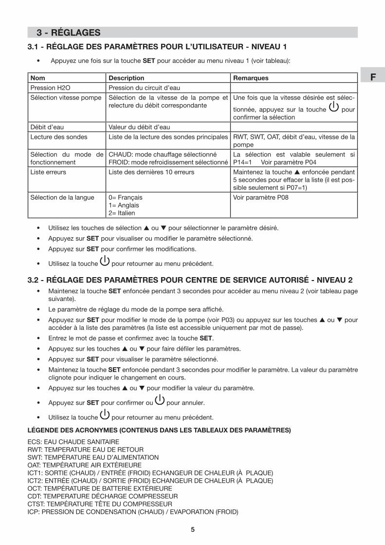
3.2 - réglage deS ParamètreS Pour Centre de SerViCe autoriSé - niVeau 2• Maintenezlatouche Set enfoncée pendant3secondespouraccéderaumenuniveau2(voirtableaupage
suivante).
• Leparamètrederéglagedumodedelapompeseraaffiché.
• AppuyezsurSetpourmodifierlemodedelapompe(voirP03)ouappuyezsurlestouchess ou t pour accéderàlalistedesparamètres(lalisteestaccessibleuniquementparmotdepasse).
• EntrezlemotdepasseetconfirmezaveclatoucheSet.
• Appuyezsurlestouchess ou t pourfairedéfilerlesparamètres.
• AppuyezsurSetpourvisualiserleparamètresélectionné.
• Maintenezlatouche Set enfoncée pendant3secondespourmodifierleparamètre.Lavaleurduparamètreclignote pour indiquer le changement en cours.
• Appuyezsurlestouchess ou t pourmodifierlavaleurduparamètre.
• AppuyezsurSet pour confirmer ou pour annuler.
• Utilisezlatouche pour retourner au menu précédent.
3.1 - réglage deS ParamètreS Pour l’utiliSateur - niVeau 1
• AppuyezunefoissurlatoucheSetpouraccéderaumenuniveau1(voirtableau):
nom description remarques
Pression H2O Pression du circuit d’eau
sélection vitesse pompe sélection de la vitesse de la pompe et relecturedudébitcorrespondante
Une fois que la vitesse désirée est sélec-
tionnée, appuyez sur la touche pour confirmer la sélection
Débitd’eau Valeurdudébitd’eau
lecture des sondes liste de la lecture des sondes principales RWT,SWT,OAT,débitd’eau,vitessedelapompe
sélection du mode de fonctionnement
CHAUD: mode chauffage sélectionnéFROiD: mode refroidissement sélectionné
La sélection est valable seulement siP14=1VoirparamètreP04
liste erreurs Listedesdernières10erreurs Maintenezlatouches enfoncée pendant 5 secondes pour effacer la liste (il est pos-sibleseulementsiP07=1)
sélection de la langue 0= Français1= Anglais2= italien
VoirparamètreP08
• Utilisezlestouchesdesélections ou t poursélectionnerleparamètredésiré.
• AppuyezsurSetpourvisualiseroumodifierleparamètresélectionné.
• AppuyezsurSet pour confirmer les modifications.
• Utilisezlatouche pour retourner au menu précédent.
légende deS aCronYmeS (ContenuS danS leS taBleauX deS ParamètreS)
ECs: EAU CHAUDE sANiTAiRERWT: TEMPERATURE EAU DE RETOURsWT: TEMPÉRATURE EAU D’AliMENTATiONOAT: TEMPÉRATURE AiR ExTÉRiEUREICT1:SORTIE(CHAUD)/ENTRÉE(FROID)ECHANGEURDECHALEUR(ÀPLAQUE)ICT2:ENTRÉE(CHAUD)/SORTIE(FROID)ECHANGEURDECHALEUR(ÀPLAQUE)OCT: TEMPÉRATURE DE BATTERiE ExTÉRiEURECDT: TEMPERATURE DÉCHARGE COMPREssEURCTsT: TEMPÉRATURE TÊTE DU COMPREssEURICP:PRESSIONDECONDENSATION(CHAUD)/EVAPORATION(FROID)
3 - réglageS

6
F
6
no
m.
des
crip
tio
nu
nité
Vale
ur p
ar d
éfau
tin
terv
alle
aug
men
-ta
tio
nd
escr
ipti
on
de
la v
aleu
rr
emar
que
sP
lanc
her
Vent
ilo-
conv
ecte
urs
rad
iate
urs
min
.m
ax.
-le
ctur
e d
es
sond
esle
ctur
e se
ulem
ent
RW
T -
sW
T -
OAT
- iC
T1 -
iCT2
- O
CT
CD
T -
CTs
T -
iCP
Déb
itd’eau
Vite
sse
de
la p
omp
e
list
e d
e to
utes
les
vale
urs
des
son
des
P02
Rég
lage
On-Off(hysté
-résis)
°C1.
51.
51.
50.
510
0.5
Hystérésisredém
arrage
delapom
peà
chal
eur
sur
la t
emp
érat
ure
d’e
au d
e re
tour
Voir
grap
hiq
ue «
HY
sTÉ
RÉ
sis
ON
/OFF
»
P03
Mod
e p
omp
e d
’eau
-Auto(0)
Auto(0)
Auto(0)
Auto(0)
ON(1
)1
AU
TO=
mod
e au
tom
atiq
ueO
N=
pom
pe
touj
ours
allu
mée
P04
Mod
e d
e fo
nc-
tionn
emen
t-
Cha
ud(0
)Cha
ud(0
)Cha
ud(0
)Cha
ud(0
)Froid(1
)1
CH
AU
DE
= m
ode
chau
ffage
sél
ectio
nné
FRO
iD=
mod
e re
froi
dis
sem
ent
séle
ctio
nné
Lasélec
tiones
tva
lableseu
lemen
tsiP14
=1
P05
Mod
e d
e co
nsig
ne-
00
00
11
0=con
sign
eau
tomatique
(cou
rbeclim
a-tiq
ue)
1=con
sign
efix
e(sélec
tiondel’u
tilisateu
r)
Pou
rl’a
pplication2zo
ne,laco
nsigne
laplus
chau
dees
tsé
lectionn
ée(m
odech
auffa
ge)o
ulaplusfroide(m
oderefroidisse
men
t)
P06
Pom
pe
d’e
au
seco
ndai
re-
00
00
11
0= s
eule
men
t la
pom
pe
de
l’uni
té1=
pom
pe
seco
ndai
re in
stal
lée
(circ
uit
prim
aire/sec
ondaire)
P07
Rem
iseàzé
rolis
te d
’err
eur
-0
00
01
10=
rem
iseàzé
roin
terdit
1=rem
iseàzé
ropermis
SiP
07=1pas
seàla
listedes
erreu
rset
mainten
ezla
tou
che
s p
end
ant
5 se
cond
es
pou
r ef
face
r la
list
e
P08
lang
ue-
Ang
lais(1
)Ang
lais(1
)Ang
lais(1
)0
21
0= F
ranç
ais
1= A
ngla
is2=
ital
ien
P09
Cha
uffa
ge
d’a
pp
oint
-0
00
03
10=
cha
uffa
ge d
’ap
poi
nt n
on a
ctif
1= c
hauf
fage
d’a
pp
oint
ext
érie
ur a
ctif
2= r
ésis
tanc
e in
tern
e ac
tive
3= c
hauf
fage
ext
érie
ur +
rés
ista
nce
inte
rne
activ
es
Lesva
leurs2et3son
tva
lablesse
ulem
ent
pou
r A
qua
Uni
ts
i les
val
eurs
2 o
u 3
sont
sél
ectio
nnée
s pou
rlesun
itésiM
,l’unitéfo
nctio
nnese
lonla
vale
ur 1
P10
Ret
ard
cha
uffa
ge
d’a
pp
oint
Min
.20
2020
512
01
Tem
ps
de
fonc
tionn
emen
t d
e la
pom
pe
à ch
aleu
r av
ant
l’act
ivat
ion
du
chau
ffage
d
’ap
poi
nt
Valableseu
lemen
tsiP40
<O
AT<P12
Voir
grap
hiq
ue «
PlA
GE
DE
FO
NC
TiO
NN
E-
ME
NT
DE
lA
PO
MP
E À
CH
AlE
UR
/ C
HA
UF-
FAG
E D
’AP
PO
iNT»
P11
Mod
e B
oost
-0
00
01
10=
mod
e B
oost
dés
activ
é1=
mod
e B
oot
activ
eSiP
11=1,le
cha
uffage
d’appoint(s
elon
P09
)se
ra a
ctiv
é im
méd
iate
men
t ju
squ’
à ce
que
lacon
sign
eso
itatteinte,p
uisP11
rev
ient
auto
mat
ique
men
t à
0
P12
seu
il ch
auffa
ge
d’a
pp
oint
°C-1
0-1
0-1
0P
40+
351
Mod
e ch
auffa
ge:
OAT
> P
12: c
hauf
fage
d’a
pp
oint
dés
activ
éOAT
<P12
:cha
uffage
d’appointactif
Voir
grap
hiq
ue «
PlA
GE
DE
FO
NC
TiO
NN
E-
ME
NT
DE
lA
PO
MP
E À
CH
AlE
UR
/ C
HA
UF-
FAG
E D
’AP
PO
iNT»
P13
Ret
ard
van
ne
EC
ss
ec.
1515
1515
300
5Te
mp
s p
ris p
ar la
van
ne E
Cs
pou
r p
asse
r d
’une
pos
ition
à l’
autr
e
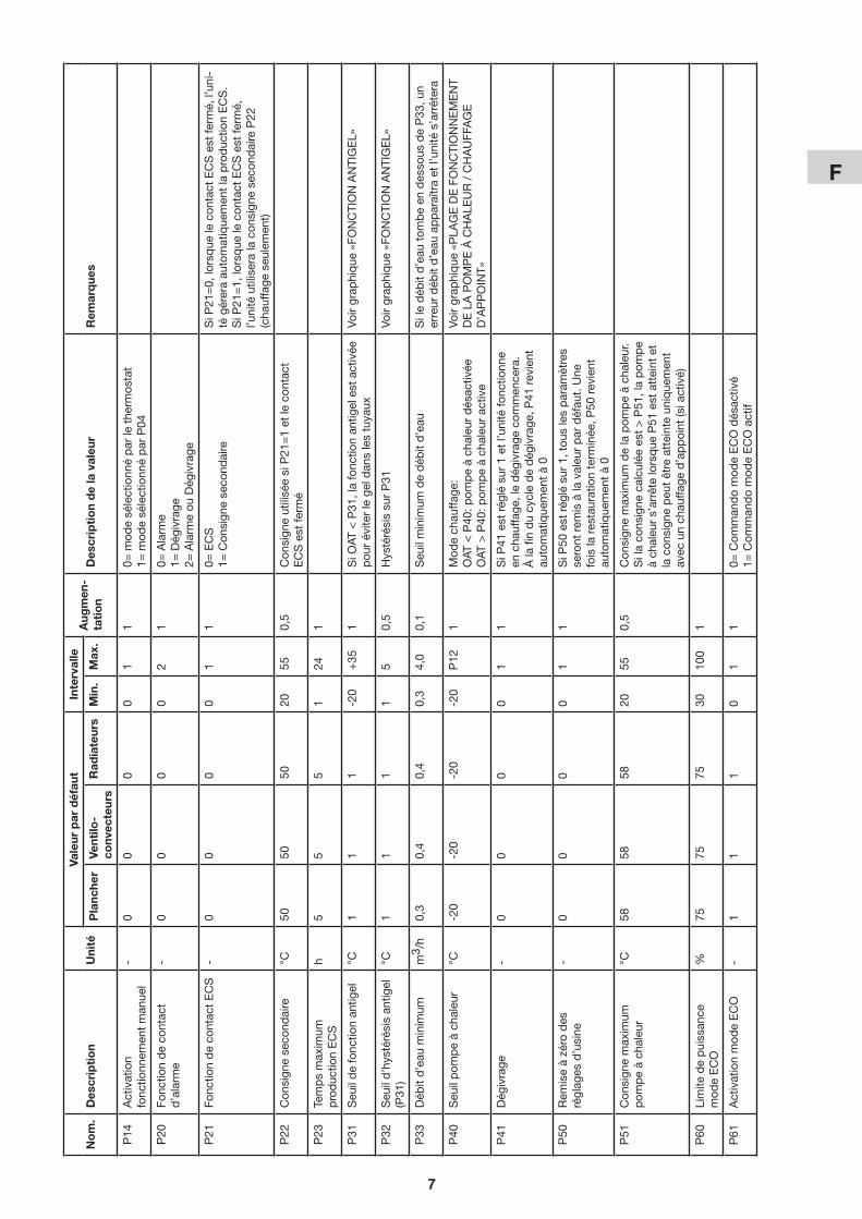
3.2.1 - réglage deS ParamètreS générauX
7
F
7
no
m.
des
crip
tio
nu
nité
Vale
ur p
ar d
éfau
tin
terv
alle
aug
men
-ta
tio
nd
escr
ipti
on
de
la v
aleu
rr
emar
que
sP
lanc
her
Vent
ilo-
conv
ecte
urs
rad
iate
urs
min
.m
ax.
P14
Act
ivat
ion
fonc
tionn
emen
t m
anue
l-
00
00
11
0= m
ode
séle
ctio
nné
par
le t
herm
osta
t1=
mod
e sé
lect
ionn
é p
ar P
04
P20
Fonc
tion
de
cont
act
d’a
larm
e-
00
00
21
0= A
larm
e1=
Dég
ivra
ge2=
Ala
rme
ou D
égiv
rage
P21
Fonc
tion
de
cont
act
EC
s-
00
00
11
0= E
Cs
1= C
onsi
gne
seco
ndai
reSiP
21=0,lo
rsque
lecon
tactECSestfe
rmé,l’un
i-té
gér
era
auto
mat
ique
men
t la
pro
duc
tion
EC
s.
SiP
21=1,lo
rsque
lecon
tactECSestfe
rmé,
l’uni
té u
tilis
era
la c
onsi
gne
seco
ndai
re P
22
(cha
uffage
seu
lemen
t)
P22
Con
sign
e se
cond
aire
°C50
5050
2055
0,5
Con
sign
e ut
ilisé
e si
P21
=1
et le
con
tact
E
Cs
est
ferm
é
P23
Tem
ps
max
imum
pro
duc
tion
EC
s
h5
55
124
1
P31
seu
il d
e fo
nctio
n an
tigel
°C1
11
-20
+35
1SiO
AT<P31
,lafonc
tionan
tigelestactivée
pou
rév
iterlegeldan
slestuya
uxVo
ir gr
aphi
que
«FO
NC
TiO
N A
NTi
GE
l»
P32
Seu
ild’hystérésisan
tigel
(P31
)°C
11
11
50,5
Hystérésissu
rP31
Voir
grap
hiq
ue «
FON
CTi
ON
AN
TiG
El»
P33
Déb
itd’eau
minim
umm
3 /h
0,3
0,4
0,4
0,3
4,0
0,1
Seu
ilminim
umdedéb
itd’eau
Siledéb
itd’eau
tom
been
des
sous
deP33
,un
erreurdéb
itd’eau
apparaîtraetl’un
ités’arrêtera
P40
seu
il p
omp
e à
chal
eur
°C-2
0-2
0-2
0-2
0P
121
Mod
e ch
auffa
ge:
OAT
<P40
:pom
peàch
aleu
rdés
activ
éeO
AT >
P40
: pom
pe
à ch
aleu
r ac
tive
Voir
grap
hiq
ue «
PlA
GE
DE
FO
NC
TiO
NN
EM
EN
T D
E l
A P
OM
PE
À C
HA
lEU
R /
CH
AU
FFA
GE
D
’AP
PO
iNT»
P41
Dég
ivra
ge-
00
00
11
si P
41 e
st r
églé
sur
1 e
t l’u
nité
fonc
tionn
e en
cha
uffage
,ledég
ivrage
com
men
cera.
Àla
finducy
clededég
ivrage
,P41
rev
ient
auto
mat
ique
men
t à
0
P50
Rem
iseàzé
rodes
ré
glag
es d
’usi
ne-
00
00
11
SiP
50estrég
lésur1,tou
slesparam
ètres
sero
nt r
emis
à la
val
eur
par
déf
aut.
Une
foisla
res
taurationterm
inée
,P50
rev
ient
auto
mat
ique
men
t à
0
P51
Con
sign
e m
axim
um
pom
pe
à ch
aleu
r°C
5858
5820
550,5
Con
sign
e m
axim
um d
e la
pom
pe
à ch
aleu
r.Silaco
nsigne
calcu
léees
t>P51
,lapom
pe
àch
aleu
rs’arrêtelo
rsque
P51
estatteintet
lacon
sign
epeu
têtreatteinteun
ique
men
tav
ecunch
auffa
ged’appoint(s
iactivé)
P60
lim
ite d
e p
uiss
ance
mod
e E
CO
%75
7575
3010
01
P61
Act
ivat
ion
mod
e E
CO
-1
11
01
10=
Com
man
do
mod
e E
CO
dés
activ
é1=
Com
man
do
mod
e E
CO
act
if
8
F
8
no
m.
des
crip
tio
nu
nité
Vale
ur p
ar d
éfau
tin
terv
alle
aug
men
-ta
tio
nd
escr
ipti
on
de
la v
aleu
rr
emar
que
sP
lanc
her
Vent
ilo-
conv
ecte
urs
rad
iate
urs
min
.m
ax.
P10
1Typed’in
stallatio
n(zon
eun
ique
ouzo
ne1)
-0
12
02
10=
Pla
nche
r1=
Ven
tilo-
conv
ecte
urs
2=Rad
iateursàbas
setem
pérature
Lorsque
P10
1es
tmod
ifié,P10
5/P10
6P
120
/ P
121
/ P
123
son
t ré
initi
alis
és à
la
vale
ur p
ar d
éfau
t co
rres
pon
dan
te
P10
5Con
sign
emax
imum
cou
rbe
clim
atique
(zon
eun
ique
ou
zone
1)
°C35
4550
3055
0,5
seu
lem
ent
pou
r m
ode
chau
ffage
Voirgrap
hique
«COURBECLIMAT
IQUE»
P10
6Con
sign
eminim
umcou
rbe
clim
atique
(zon
eun
ique
ou
zone
1)
°C20
3540
2040
0,5
Voirgrap
hique
«COURBECLIMAT
IQUE»
P12
0Te
mp
érat
ure
pou
r co
nsig
ne
max
imum
(zon
eun
ique
ou
zone
1)
°C-7
-7-7
-20
P12
10,5
Rég
ler
la t
emp
érat
ure
régi
onal
e m
inim
ale
pré
vue
(voi
r gr
aphi
que
« C
OU
RB
E C
liM
A-
TIQUE»)
P12
1Te
mp
érat
ure
pou
r co
nsig
ne
minim
um(z
oneun
ique
ou
zone
1)
°C17
1717
P12
0+
350,5
SiP
121<P12
0,P12
0es
trégléau
tomati-
que
men
t su
r P
121
Voirgrap
hique
«COURBECLIMAT
IQUE»
P12
3C
onsi
gne
de
refr
oid
isse
men
t (zon
eun
ique
ouzo
ne1)
°C23
12-
1030
0,5
En
refr
oid
isse
men
t la
con
sign
e es
t fix
e et
co
rres
pon
de
à P
123
P13
0Con
sign
eca
lculé(zon
eun
ique
ou
zon
e1)
°Cle
ctur
e se
ulem
ent
P13
1C
onsi
gne
de
refr
oid
isse
men
t plusbas
seave
cco
ntrôle
0-10
V(z
oneun
ique
ouzo
ne1)
°C23
12-
10P
132
0,5
Actifse
ulem
entsiP15
0=1,corresp
ondeà
un s
igna
le d
e 10
VVo
ir gr
aphi
que
«C
ON
TRô
lE 0
-10V
»
P13
2C
onsi
gne
de
refr
oid
isse
men
t plusha
uteav
eccon
trôle
0-10
V(z
oneun
ique
ouzo
ne1)
°C30
30-
P13
130
0,5
Actifse
ulem
entsiP15
0=1,corresp
ondeà
unsigna
lede0V
.SiP
132<P13
1,P13
2es
tré
glé
auto
mat
ique
men
t su
r P
131
Voir
grap
hiq
ue «
CO
NTR
ôlE
0-1
0V
P15
0Fo
nctio
n d
e si
gnal
0-1
0V
(zon
eun
ique
ouzo
ne1)
-0
00
04
10=
Dés
activ
é1=
Cha
rge
ther
miq
ue2=
Com
man
de
de
cons
igne
3= C
harg
e th
erm
ique
sur
uni
té
exté
rieur
e4=
Com
man
de
de
cons
igne
sur
un
ité e
xtér
ieur
e
SiP
150=
3ou
4,lesign
al0-10V
estlu
un
ique
men
t su
r l’u
nité
ext
érie
ure
et le
s sign
ales
delazon
e1et2seron
tigno
rés
Voir
grap
hiq
ue «
CO
NTR
ôlE
0-1
0V
P15
1C
hang
emen
t d
e co
nsig
ne
max
imum
0-1
0V°C
55
51
100,5
Act
if se
ulem
ent
en m
ode
de
chau
ffage
et
si
P15
0=1.
il r
épre
sent
le c
hang
emen
t d
e la
co
nsig
ne a
vec
un s
igna
le d
e 10
VVo
ir gr
aphi
que
«C
ON
TRô
lE 0
-10V
P15
2C
hang
emen
t m
anue
l de
cons
igne
°C0
00
010
0,5
Acc
rois
sem
ent
man
uel d
e co
nsig
ne d
e la
co
urbeclim
atique
ench
auffa
ge
P16
0R
etar
d v
anne
de
mél
ange
sec
6060
6030
300
5
P16
1Typedeco
ntrôlevan
nede
mél
ange
-0
00
01
10=con
trôle23
0Va
c(2ou3points)
1=con
trôle0-10
V
• Pourréglerlazoneuniqueoulazone1utiliserlesparamètresdeP101àP161(voirtableau).
3.2.2 - réglage de la Zone uniQue ou de la Zone 1
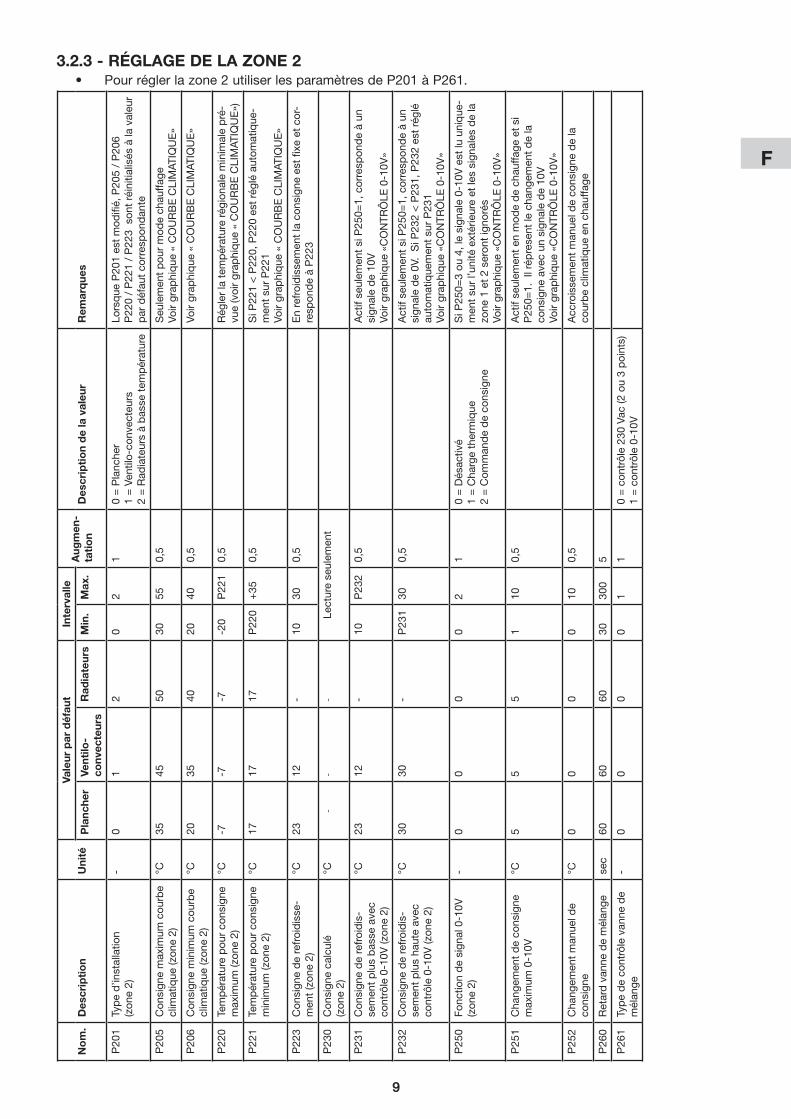
9
F
9
no
m.
des
crip
tio
nu
nité
Vale
ur p
ar d
éfau
tin
terv
alle
aug
men
-ta
tio
nd
escr
ipti
on
de
la v
aleu
rr
emar
que
sP
lanc
her
Vent
ilo-
conv
ecte
urs
rad
iate
urs
min
.m
ax.
P20
1Typed’in
stallatio
n(zon
e2)
-0
12
02
10
= P
lanc
her
1 =
Ven
tilo-
conv
ecte
urs
2=Rad
iateursàbas
setem
pérature
Lorsque
P20
1es
tmod
ifié,P20
5/P20
6P
220
/ P
221
/ P
223
son
t ré
initi
alis
és à
la v
aleu
r p
ar d
éfau
t co
rres
pon
dan
te
P20
5Con
sign
emax
imum
cou
rbe
clim
atique
(zon
e2)
°C35
4550
3055
0,5
seu
lem
ent
pou
r m
ode
chau
ffage
Voirgrap
hique
«COURBECLIMAT
IQUE»
P20
6Con
sign
eminim
umcou
rbe
clim
atique
(zon
e2)
°C20
3540
2040
0,5
Voirgrap
hique
«COURBECLIMAT
IQUE»
P22
0Te
mp
érat
ure
pou
r co
nsig
ne
max
imum
(zon
e2)
°C-7
-7-7
-20
P22
10,5
Rég
ler
la t
emp
érat
ure
régi
onal
e m
inim
ale
pré
-vu
e(voirgrap
hique
«COURBECLIMAT
IQUE»)
P22
1Te
mp
érat
ure
pou
r co
nsig
ne
minim
um(z
one2)
°C17
1717
P22
0+
350,5
SiP
221<P22
0,P22
0es
trégléau
tomatique
-m
ent
sur
P22
1 Vo
irgrap
hique
«COURBECLIMAT
IQUE»
P22
3C
onsi
gne
de
refr
oid
isse
-men
t(zon
e2)
°C23
12-
1030
0,5
En
refr
oid
isse
men
t la
con
sign
e es
t fix
e et
cor
-re
spon
de
à P
223
P23
0C
onsi
gne
calc
ulé
(zon
e2)
°C-
--
lect
ure
seul
emen
t
P23
1C
onsi
gne
de
refr
oid
is-
semen
tplusbas
seave
cco
ntrôle0-10V
(zon
e2)
°C23
12-
10P
232
0,5
Actifse
ulem
entsiP25
0=1,corresp
ondeàun
si
gnal
e d
e 10
VVo
ir gr
aphi
que
«C
ON
TRô
lE 0
-10V
»
P23
2C
onsi
gne
de
refr
oid
is-
sem
ent
plu
s ha
ute
avec
co
ntrôle0-10V
(zon
e2)
°C30
30-
P23
130
0,5
Actifse
ulem
entsiP25
0=1,corresp
ondeàun
sign
alede0V
.SiP
232<P23
1,P23
2es
tréglé
auto
mat
ique
men
t su
r P
231
Voir
grap
hiq
ue «
CO
NTR
ôlE
0-1
0V»
P25
0Fo
nctio
n d
e si
gnal
0-1
0V
(zon
e2)
-0
00
02
10
= D
ésac
tivé
1 =
Cha
rge
ther
miq
ue
2 =
Com
man
de
de
cons
igne
SiP
250=
3ou
4,lesign
ale0-10
Vestlu
unique
-m
ent
sur
l’uni
té e
xtér
ieur
e et
les
sign
ales
de
la
zone
1et2se
rontig
norés
Voir
grap
hiq
ue «
CO
NTR
ôlE
0-1
0V»
P25
1C
hang
emen
t d
e co
nsig
ne
max
imum
0-1
0V°C
55
51
100,5
Act
if se
ulem
ent
en m
ode
de
chau
ffage
et
si
P25
0=1.
il r
épre
sent
le c
hang
emen
t d
e la
co
nsig
ne a
vec
un s
igna
le d
e 10
VVo
ir gr
aphi
que
«C
ON
TRô
lE 0
-10V
»
P25
2C
hang
emen
t m
anue
l de
cons
igne
°C0
00
010
0,5
Acc
rois
sem
ent
man
uel d
e co
nsig
ne d
e la
co
urbeclim
atique
ench
auffa
ge
P26
0R
etar
d v
anne
de
mél
ange
sec
6060
6030
300
5
P26
1Typedeco
ntrôlevan
nede
mél
ange
-0
00
01
10=con
trôle23
0Va
c(2ou3points)
1=con
trôle0-10
V
• Pourréglerlazone2utiliserlesparamètresdeP201àP261.3.2.3 - réglage de la Zone 2

10
F
4 - graPHiQueS
4.1 - HYStéréSiS on/oFF
Températureeau de retourP130
(consigne)
Pompe à chaleurallumée
P02
Pompe à chaleuréteinte
4.2 - Plage de FonCtionnement de la PomPe À CHaleur / CHauFFage d’aPPoint
P40 P12Températureair extérieure
Pompe à chaleur+
chauffaged’appoint
Séulementpompe à chaleur
Séulementchauffaged’appoint
4.3 - CourBe ClimatiQue (mode de CHauFFage)
X
Y
P105
P106
P120 P121
P130 (consigne)
Températureair extérieure
Consigneeau de retour
4.4 - FonCtion antigel
Températureair extérieureP31
Fonction antigelactivée
Fonction antigelpas activée
P32
si la fonction antigel est activée:
Températureeau de retour(RWT)
5°C
Unité en fonction forcée pour le chauffage de l'eau
Unité en fonctionnement normal
15°C

11
F
X
Y
P105
P106
P120 P121
P130 (consigne)
Températureair extérieure
Consigneeau de retour
Charge thermique(P150 = 1) Y+Z
Z = P151 * (0-10V)%
Exemple:P151 = 5°CSignal 0-10V = 6V = 60%Z = 5°C * 60% = 3°C
P105
P106
Consigneeau de retour
Commande de consigne(P150 = 2)
0-10V0V 10V
P130 (consigne)
X
Y
CHAUFFAGE
P132
P131
Consigneeau de retour
0-10V0V 10V
P130 (consigne)
X
Y
REFROIDISSEMENT
4.5 - ContrÔle 0-10V
remarQue:Lesgraphiquesquiseréfèrentauxparamètresdelazone1sontidentiquespourlazone2aveclesparamètrescorrespondants.

12
F
ViaAlfenoVaro,35-25020Alfianello-BS-Italy
Tel.+390331755111-Fax+390331755501
www.argoclima.com