Embed Size (px)
Citation preview
Co
ntr
ol
& P
ow
er,
In
c.
-
1.8
77.8
35.5
274
-
ww
w.c
on
tro
lan
dp
ow
er.
co
m

4 Way/2 and 3 Position4
Four ported valves are generally used to operatedouble-acting cylinders or actuators.
They have four or five pipe connections,commonly called ports: � One pressure inlet.� Two cylinder ports providing pressure to the
double-acting cylinder or actuator.� One or two outlets to exhaust pressure from
the cylinders.
In a de-energized position, pressure is connectedto one cylinder port; the other port is connectedto the exhaust. In an energized position, pressureand exhaust are reversed.
Four ports means less piping is required. With fiveports, independent speed controls can bemounted in each port.
Three Types of Constructions Apply:Single SolenoidWhen the solenoid is energized, the valve shifts, thenreturns to the original position when de-energized.
Dual SolenoidWhen one solenoid is energized, the valve shifts,then returns when the other solenoid is energized.They may be energized momentarily or continu-ously, but never concurrently. Some valves, bothsingle and dual solenoid, may change position onloss of fluid pressure.
Single Air Operator When the operator is pressurized, the valve shifts,then returns when the pressure is removed.
See Engineering Section for further details.
Standard and Optional Features:Solenoid valves are supplied, as listed, with either Red-Hat II® molded epoxy solenoids or Red-Hat®
solenoids with metal enclosures (except for Series8401). Red-Hat II valves are identified by the letter“G” or “H” in their catalog numbers; e.g., 8344G27.Many optional features may be added to your valves;e.g., high-temperature Class H molded coils andmanual operators. See the Optional Features Sectionfor details.
4.00
Index
4 and 5 Ported Valves Flow Diagrams
De-Energized
Press. Cyl.
A
Cyl.
B
Exh.
Energized
Press. Cyl.
A
Cyl.
B
Exh.
Single SolenoidCyl. B
Cyl. B Cyl. A
Exh. 4 Press. Exh. 2
Cyl. B Cyl. A
Exh. 4 Press. Exh. 2
Cyl. B Cyl. A
Exh. 4 Press. Exh. 2
Cyl. B Cyl. A
Exh. 4 Press. Exh. 2
Press. Exh. Press. Exh.
Cyl. A
Cyl. B
Press. Exh.
Cyl. A Cyl. B
Press. Exh.
Cyl. A
Cyl. B Cyl. A
Dual Solenoid
Single Solenoid Dual Solenoid
DeEnergized Solenoid A Last Energized
DeEnergized Solenoid A Last Energized
Energized Solenoid B Last Energized
Energized Solenoid B Last Energized
Typical 4 Ported
Typical 5 Ported
Series General Description Pipe Size (NPT) Page Number
8340 Air Only 1/4" 4.01
8342 General Service 1/4" and 3/8 4.05
8344 Piston/Poppet 1/4" 1" 4.07
8345 Compact General Service 1/4" 4.09
8401/8402 Miniature Slide 1/8" and 1/4" 4.11
8551 Stainless Steel 1/4" 4.15
Directional Control 4.17Index
Co
ntr
ol
& P
ow
er,
In
c.
-
1.8
77.8
35.5
274
-
ww
w.c
on
tro
lan
dp
ow
er.
co
m

Features
• Aironly design for cylinder control.
• Up to eight single and dual solenoid valves, in any combination, can be manifolded.
• SubBase constructions have separate cylinder connections and common pressure and exhaust connections at each end.Can be assembled in the field by simply inserting tie rods through holes in base.
• GroupMounted constructions have common pressure connections at each end and separate cylinder and exhaust connections.
• Can be factory assembled or grouped in the field with strong snapon clamps, supplied.
4.01 R1
Direct Acting
Air-Only Solenoid ValvesAluminum Body • In-Line, Sub-Base, and Group Mounted
1/4" NPT
B
E
A
P4/2SERIES
8340
Solenoid Enclosures
Electrical
Nominal Ambient Temperature Ranges:
AC: 32˚F to 125˚F (0˚C to 52˚C)
DC: 32˚F to 77˚F (0˚C to 25˚C)(104˚F/40˚C occasionally)
Refer to Engineering Section for details.
Leakage: Breakin leakage rate of 2 SCFH is reduced
to a very slight amount as the valve wears in.
Approvals:CSA certified. AC is UL listed as General Purpose Valve.
RedHat II meets applicable CE directives.
Refer to Engineering Section for details.
Construction
Standard: RedHat II Watertight, Types 1, 2, 3, 3S, 4, and 4X; RedHat Type 1.
Optional: RedHat II Explosionproof and Watertight, Types 3, 3S, 4, 4X, 6,
6P, 7, and 9 (For 8340G1 and 8340G2 only); RedHat Types 3, 4,
4X, 7, and 9. (To order, add prefix “EF” to catalog number.)See Optional Features Section for other available options.
Valve Parts in Contact with Fluids
Body Hard Anodized Aluminum
Disc PE
Core Tube 305 Stainless Steel
Core and Plugnut 430F Stainless Steel
Core Spring 302 Stainless Steel
Shading Coil Copper
Seals NBR
Miscellaneous PA, CA
StandardCoil andClass of Insulation
Watt Rating and PowerConsumption Spare Coil Part No.
DCWatts
AC General Purpose Explosionproof
WattsVA
HoldingVA
Inrush AC DC AC DCF 10.5 24 65 64982 64982 F 19.7 16.7 36 85 64982 66611 64982 66611F 10.1 25 70 238610 238614 F 22.6 17.1 40 93 238610 238710 238614 238714
Standard Voltages: 24, 120, 240, 480 volts AC, 60 Hz (or 110, 220 volts AC, 50 Hz). 6, 12, 24, 120, 240 volts DC. Must be specified when ordering. Other voltages available when required.
%
^
)
4qwer
Index
Co
ntr
ol
& P
ow
er,
In
c.
-
1.8
77.8
35.5
274
-
ww
w.c
on
tro
lan
dp
ow
er.
co
m
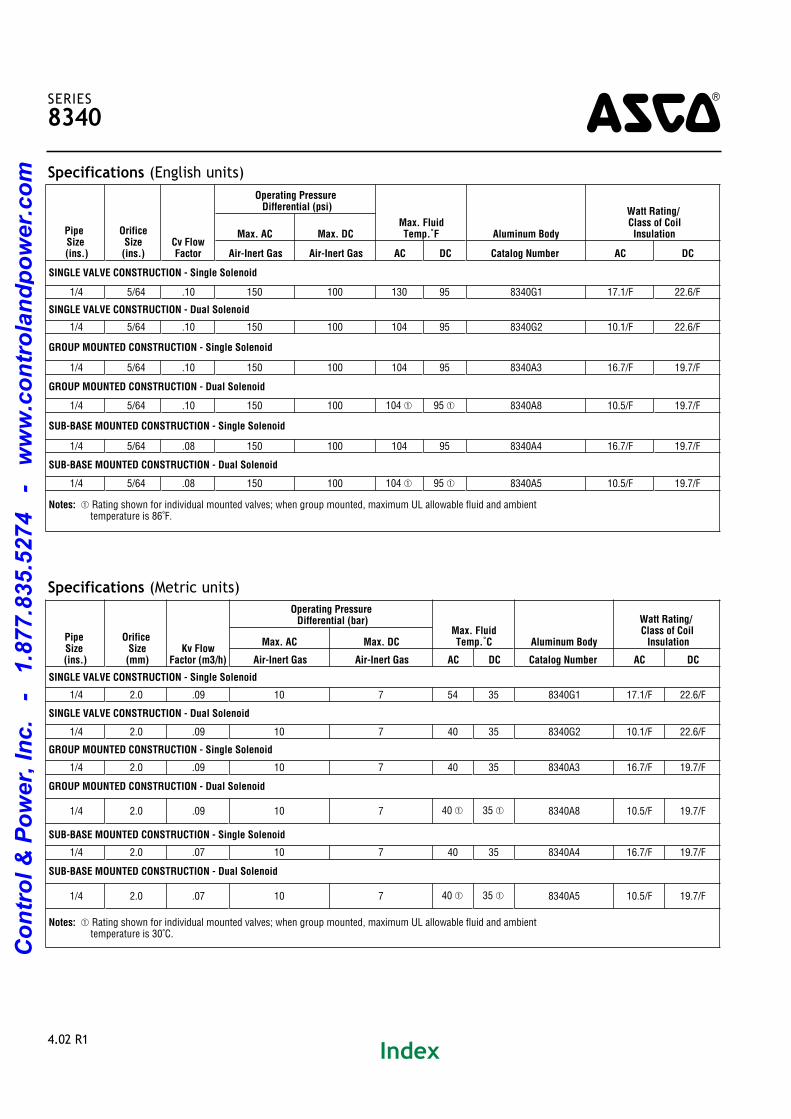
Specifications (Metric units)
Specifications (English units)
4SERIES
8340
4.02 R1
PipeSize
(ins.)
Orifice Size (ins.)
Cv FlowFactor
Operating Pressure Differential (psi)
Max. Fluid Temp.˚F Aluminum Body
Watt Rating/ Class of Coil InsulationMax. AC Max. DC
Air-Inert Gas Air-Inert Gas AC DC Catalog Number AC DC
SINGLE VALVE CONSTRUCTION - Single Solenoid
1/4 5/64 .10 150 100 130 95 8340G1 17.1/F 22.6/F
SINGLE VALVE CONSTRUCTION - Dual Solenoid
1/4 5/64 .10 150 100 104 95 8340G2 10.1/F 22.6/F
GROUP MOUNTED CONSTRUCTION - Single Solenoid
1/4 5/64 .10 150 100 104 95 8340A3 16.7/F 19.7/F
GROUP MOUNTED CONSTRUCTION - Dual Solenoid
1/4 5/64 .10 150 100 104 � 95 � 8340A8 10.5/F 19.7/F
SUB-BASE MOUNTED CONSTRUCTION - Single Solenoid
1/4 5/64 .08 150 100 104 95 8340A4 16.7/F 19.7/F
SUB-BASE MOUNTED CONSTRUCTION - Dual Solenoid
1/4 5/64 .08 150 100 104 � 95 � 8340A5 10.5/F 19.7/F
Notes: � Rating shown for individual mounted valves; when group mounted, maximum UL allowable fluid and ambient temperature is 86˚F.
PipeSize(ins.)
Orifice Size (mm)
Kv FlowFactor (m3/h)
Operating Pressure Differential (bar)
Max. FluidTemp.˚C Aluminum Body
Watt Rating/ Class of Coil InsulationMax. AC Max. DC
Air-Inert Gas Air-Inert Gas AC DC Catalog Number AC DC
SINGLE VALVE CONSTRUCTION - Single Solenoid
1/4 2.0 .09 10 7 54 35 8340G1 17.1/F 22.6/F
SINGLE VALVE CONSTRUCTION - Dual Solenoid
1/4 2.0 .09 10 7 40 35 8340G2 10.1/F 22.6/F
GROUP MOUNTED CONSTRUCTION - Single Solenoid
1/4 2.0 .09 10 7 40 35 8340A3 16.7/F 19.7/F
GROUP MOUNTED CONSTRUCTION - Dual Solenoid
1/4 2.0 .09 10 7 40 � 35 � 8340A8 10.5/F 19.7/F
SUB-BASE MOUNTED CONSTRUCTION - Single Solenoid
1/4 2.0 .07 10 7 40 35 8340A4 16.7/F 19.7/F
SUB-BASE MOUNTED CONSTRUCTION - Dual Solenoid
1/4 2.0 .07 10 7 40 � 35 � 8340A5 10.5/F 19.7/F
Notes: � Rating shown for individual mounted valves; when group mounted, maximum UL allowable fluid and ambient temperature is 30˚C.
Index
Co
ntr
ol
& P
ow
er,
In
c.
-
1.8
77.8
35.5
274
-
ww
w.c
on
tro
lan
dp
ow
er.
co
m

4SERIES
8340
4.03 R1
Dimensions: inches (mm)
SUB-BASE MOUNTED SINGLE AND DUAL
SOLENOID CONSTRUCTION
SINGLE VALVE CONSTRUCTION - SINGLE AND DUAL SOLENOIDS
Note: Dual solenoid shown dotted in.
Index
Co
ntr
ol
& P
ow
er,
In
c.
-
1.8
77.8
35.5
274
-
ww
w.c
on
tro
lan
dp
ow
er.
co
m

4.04 R1
Dimensions: inches (mm)
4SERIES
8340
Mounting Brackets
CatalogNumber
With General PurposeSolenoid Enclosure
When Manual OperatorIs Used
8340G1 Mounting Holes on Body Order Kit No. 206737
8340G2 Standard NA
8340A3 Mounting Holes on Body Order Kit No. 206554
8340A4 Mounting Holes on Body NA
8340A5 Mounting Holes on Body NA
8340A8
Standard when factoryassembled, but must order
Kit No. 206554 for individualvalves.
NA
NA Not Available.
GROUP MOUNTED CONSTRUCTION
SINGLE SOLENOID
GROUP MOUNTED CONSTRUCTION - DUAL SOLENOID
SUB-BASE MOUNTED CONSTRUCTION
(Shown as Group Mounted)
Index
Co
ntr
ol
& P
ow
er,
In
c.
-
1.8
77.8
35.5
274
-
ww
w.c
on
tro
lan
dp
ow
er.
co
m
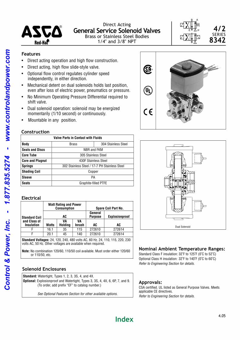
Features
• Direct acting operation and high flow construction.
• Direct acting, high flow slidestyle valve.
• Optional flow control regulates cylinder speed independently, in either direction.
• Mechanical detent on dual solenoids holds last position,even after loss of electric power, pneumatics or pressure.
• No Minimum Operating Pressure Differential required toshift valve.
• Dual solenoid operation: solenoid may be energized momentarily (1/10 second) or continuously.
• Mountable in any position.
4.05
Direct Acting
General Service Solenoid ValvesBrass or Stainless Steel Bodies
1/4" and 3/8" NPT
B
E
A
P 4/2SERIES
8342
Solenoid Enclosures
Electrical
Nominal Ambient Temperature Ranges:Standard Class F insulation: 32˚F to 125˚F (0˚C to 52˚C)
Optional Class H insulation: 32˚F to 140˚F (0˚C to 60˚C)
Refer to Engineering Section for details.
Approvals:CSA certified. UL listed as General Purpose Valves. Meetsapplicable CE directives.
Refer to Engineering Section for details.
Construction
Standard: Watertight, Types 1, 2, 3, 3S, 4, and 4X.
Optional: Explosionproof and Watertight, Types 3, 3S, 4, 4X, 6, 6P, 7, and 9. (To order, add prefix “EF” to catalog number.)
See Optional Features Section for other available options.
Valve Parts in Contact with Fluids
Body Brass 304 Stainless Steel
Seals and Discs NBR and FKM
Core Tube 305 Stainless Steel
Core and Plugnut 430F Stainless Steel
Springs 302 Stainless Steel / 177 PH Stainless Steel
Shading Coil Copper
Sleeve PA
Seats Graphitefilled PTFE
Standard Coil and Class of Insulation
Watt Rating and PowerConsumption Spare Coil Part No.
ACGeneralPurpose Explosionproof
WattsVA
HoldingVA
Inrush AC ACF 16.1 35 115 272610 272614
F 20.1 45 140 272610 272614
Standard Voltages: 24, 120, 240, 480 volts AC, 60 Hz. 24, 110, 115, 220, 230 volts AC, 50 Hz. Other voltages are available when required.
Note: No combination 120/60, 110/50 coil available. Must order either 120/60 or 110/50, etc.
%
^
)
Dual Solenoid
4qwer
Index
Co
ntr
ol
& P
ow
er,
In
c.
-
1.8
77.8
35.5
274
-
ww
w.c
on
tro
lan
dp
ow
er.
co
m

Specifications (Metric units)
Specifications (English units)
4SERIES
8342
4.06
Pipe Size (ins.)
OrificeSize
(ins.)Cv FlowFactor �
Operating Pressure Differential (psi)Max.Fluid.
Temp. ˚F Brass Body Stainless Steel Body
Watt Rating/ Class of Coil InsulationMaximum AC
Air-InertGas Water
Lt. Oil @300 SSU AC Catalog Number
Constr. Ref. No. Catalog Number
Constr. Ref. No. AC
SINGLE SOLENOID CONSTRUCTION
1/4 3/16 .70 125 100 100 160 8342G1 1 8342G701 2 20.1/F
3/8 3/16 .70 125 100 100 160 8342G3 1 8342G703 2 20.1/F
DUAL SOLENOID CONSTRUCTION
1/4 3/16 .70 125 125 125 160 8342G20 3 8342G720 4 16.1/F
3/8 3/16 .70 125 125 125 160 8342G22 3 8342G722 4 16.1/F
Notes: � With builtin flow control (Suffix "M"), the Cv is 0.44 and an 0.5 psi minimum operating pressure is required.
PipeSize(ins.)
Orifice Size (mm)
Kv FlowFactor
(m3/h) �
Operating Pressure Differential (bar)Max.Fluid.
Temp. ˚C Brass Body Stainless Steel Body
Watt Rating/ Class of Coil InsulationMaximum AC
Air-Inert Gas Water
Lt. Oil @300 SSU AC Catalog Number
Constr. Ref. No. Catalog Number
Constr. Ref. No. AC
SINGLE SOLENOID CONSTRUCTION
1/4 4.8 .60 9 7 7 70 8342G1 1 8342G701 2 20.1/F
3/8 4.8 .60 9 7 7 70 8342G3 1 8342G703 2 20.1/F
DUAL SOLENOID CONSTRUCTION
1/4 4.8 .60 9 9 9 70 8342G20 3 8342G720 4 16.1/F
3/8 4.8 .60 9 9 9 70 8342G22 3 8342G722 4 16.1/F
Notes: � With builtin flow control (Suffix "M"), the Kv is 0.38 and an 0.03 bar minimum operating pressure is required.
Dimensions: inches (mm)
Constr. Ref. 1, 2, 3, 4
Index
Co
ntr
ol
& P
ow
er,
In
c.
-
1.8
77.8
35.5
274
-
ww
w.c
on
tro
lan
dp
ow
er.
co
m

Features
• Sturdy, solid construction.
• Pistonoperated poppet design provides high flow.
• Can use air or water for piloting control valves.
• Wide range of sizes and flow rates.
• Single or dual solenoid construction.
• Dual solenoid can be shifted with a momentary signal and remain in position even if electrical power is lost.
• Mountable in any position.
4.07 R2
Pilot Operated
Piston/Poppet Solenoid ValvesBrass Body • 1/4" to 1" NPT
B
E
A
P
B
E
A
P 4/2SERIES
8344
Solenoid Enclosures
Electrical
Nominal Ambient Temperature Ranges:AC: 32˚F to 125˚F (0˚C to 52˚C)
DC: 32˚F to 104˚F (0˚C to 40˚C)
Refer to Engineering Section for details.
Approvals:CSA certified. Meets applicable CE directives.
Important:A Minimum Operating Pressure Differential must be
maintained between the pressure and exhaust ports. Supply
and exhaust piping must be full area, unrestricted. ASCO
flow controls and other similar components must be installed
in the cylinder lines only.
• Loss of air pressure may allow valve to shift on dual
solenoid constructions.
Construction
Standard: Watertight, Types 1, 2, 3, 3S, 4, and 4X.
Optional: Explosionproof and Watertight, Types 3, 3S, 4, 4X, 6, 6P, 7, and 9. (To order, add prefix “EF” to the catalog number.)See Optional Features Section for other available options.
StandardCoil andClass of
Insulation
Watt Rating and PowerConsumption Spare Coil Part No.
DCWatts
AC
General Purpose ExplosionproofWattsVA
HoldingVA
Inrush
F 10.6 6.1 16 30 238210 238310 238214 238314
F 11.6 10.1 25 50 238610 238710 238614 238714
F 22.6 17.1 40 70 238610 238710 238614 238714
Dual Solenoid Operation: Minimum coil ontime for dual solenoid valves is 0.3 seconds on air service and 1.0 seconds on liquids.
Caution: Do not energize both solenoids simultaneously. Refer to Engineering Section for details.
Standard Voltages: 24, 120, 240, 480 volts AC, 60 Hz (or 110, 220 volts AC, 50 Hz). 6, 12, 24, 120, 240 volts DC. Must be specified when ordering. Other voltages are available when required.
Valve Parts in Contact with Fluids
Body Brass
Seals and Disc NBR
Core Tube 305 Stainless Steel
Core and Plugnut 430F Stainless Steel
Springs 302 Stainless Steel and 177PH Stainless Steel
Shading Coil Copper
Pilot Seat Cartridge and Disc-Holder CA
Shaft Gasket Lead/Copper
%
)
4qwer
Index
Co
ntr
ol
& P
ow
er,
In
c.
-
1.8
77.8
35.5
274
-
ww
w.c
on
tro
lan
dp
ow
er.
co
m

Specifications (Metric units)
Specifications (English units)
4SERIES
8344
4.08 R2
PipeSize
(ins.)
Orifice Size (ins.)
Cv Flow Factor
Operating Pressure Differential (psi) Max. FluidTemp.˚F Brass Body
Watt Rating/ Class of Coil Insulation
�
Min.
Max. AC Max. DC
Press. Exh.Air-Inert
Gas WaterLt. Oil @ 300 SSU
Air-InertGas Water
Lt. Oil @ 300 SSU AC DC Catalog Number
Constr. Ref.No. AC DC
SINGLE SOLENOID 1/4 1/4 .80 1.0 10 150 125 125 125 125 125 180 150 8344G70 1 10.1/F 11.6/F
1/4 1/4 .80 1.0 10 250 ! 250 ! 250 ! 250 ! 250 ! 250 ! 180 180 8344G0 1 17.1/F 22.6/F
3/8 3/8 1.4 2.2 10 150 125 125 125 125 125 180 150 8344G72 2 10.1/F 11.6/F
3/8 1/4 .80 1.0 10 250 ! 250 ! 250 ! 250 ! 250 ! 250 ! 180 180 8344G1 1 17.1/F 22.6/F
1/2 3/8 1.4 2.2 10 150 125 125 125 125 125 180 150 8344G74 2 10.1/F 11.6/F
1/2 3/8 1.4 2.2 10 250 ! 250 ! 250 ! 250 ! 250 ! 250 ! 180 180 8344G27 2 17.1/F 22.6/F
3/4 3/4 5.2 5.6 10 150 125 125 125 125 125 180 150 8344G76 3 10.1/F 11.6/F
3/4 3/4 5.2 5.6 10 250 ! 250 ! 250 ! 250 ! 250 ! 250 ! 180 180 8344G29 3 17.1/F 22.6/F
1 3/4 5.2 5.6 10 150 125 125 125 125 125 180 150 8344G78 3 10.1/F 11.6/F
1 3/4 5.2 5.6 10 250 ! 250 ! 250 ! 250 ! 250 ! 250 ! 180 180 8344G31 3 17.1/F 22.6/F
DUAL SOLENOID � 1/4 1/4 .80 1.0 10 250 200 125 125 125 100 180 120 8344G44 4 6.1/F 10.6/F
3/8 3/8 1.4 2.2 10 250 200 125 125 125 100 180 120 8344G80 6 6.1/F 10.6/F
3/8 3/8 1.4 2.2 10 300 300 200 180 8344G50 7 10.1/F
1/2 3/8 1.4 2.2 10 250 200 125 125 125 100 180 120 8344G82 6 6.1/F 10.6/F
3/4 3/4 5.2 5.6 10 300 300 200 125 125 100 180 120 8344G54 8 10.1/F 10.6/F
1 3/4 5.2 5.6 10 300 300 200 125 125 100 180 120 8344G56 8 10.1/F 10.6/F
Notes: � 25 psi (1.7 bar) minimum on light oil service. � On 50 hertz service, the watt rating for the 6.1/F solenoid is 8.1 watts. ! For best results, do not use valve rated 250 psi (17 bar) on mainline pressure of less than 125 psi (9 bar).
PipeSize(ins.)
OrificeSize(mm)
Kv Flow Factor (m3/h)
Operating Pressure Differential (bar) Max. FluidTemp.˚C Brass Body
Watt Rating / Class of Coil Insulation
�
Min.
Max. AC Max. DC
Press. Exh.Air-Inert
Gas WaterLt. Oil @ 300 SSU
Air-InertGas Water
Lt. Oil @300 SSU AC DC Catalog Number
Constr. Ref.No. AC DC
SINGLE SOLENOID 1/4 6 .69 .86 0.7 10 9 9 9 9 9 81 65 8344G70 1 10.1/F 11.6/F
1/4 6 .69 .86 0.7 17 ! 17 ! 17 ! 17 ! 17 ! 17 ! 81 81 8344G0 1 17.1/F 22.6/F
3/8 10 1.2 1.89 0.7 10 9 9 9 9 9 81 65 8344G72 2 10.1/F 11.6/F
3/8 6 .69 .86 0.7 17 ! 17 ! 17 ! 17 ! 17 ! 17 ! 81 81 8344G1 1 17.1/F 22.6/F
1/2 10 1.2 1.89 0.7 10 9 9 9 9 9 81 65 8344G74 2 10.1/F 11.6/F
1/2 10 1.2 1.89 0.7 17 ! 17 ! 17 ! 17 ! 17 ! 17 ! 81 81 8344G27 2 17.1/F 22.6/F
3/4 19 4.5 4.80 0.7 10 9 9 9 9 9 81 65 8344G76 3 10.1/F 11.6/F
3/4 19 4.5 4.80 0.7 17 ! 17 ! 17 ! 17 ! 17 ! 17 ! 81 81 8344G29 3 17.1/F 22.6/F
1 19 4.5 4.80 0.7 10 9 9 9 9 9 81 65 8344G78 3 10.1/F 11.6/F
1 19 4.5 4.80 0.7 17 ! 17 ! 17 ! 17 ! 17 ! 17 ! 81 81 8344G31 3 17.1/F 22.6/F
DUAL SOLENOID � 1/4 6 .69 .86 0.7 17 14 9 9 9 7 81 48 8344G44 4 6.1/F 10.6/F
3/8 10 1.2 1.89 0.7 17 14 9 9 9 7 81 48 8344G80 6 6.1/F 10.6/F
3/8 10 1.2 1.89 0.7 21 21 14 81 8344G50 7 10.1/F
1/2 10 1.2 1.89 0.7 17 14 9 9 9 7 81 48 8344G82 6 6.1/F 10.6/F
3/4 19 4.5 4.80 0.7 21 21 14 9 9 7 81 48 8344G54 8 10.1/F 10.6/F
1 19 4.5 4.80 0.7 21 21 14 9 9 7 81 48 8344G56 8 10.1/F 10.6/F
Dimensions: inches (mm)
Constr.Ref.No. ØD E F G H J K L N P W X Y Z
ExhaustPipeSize
1 ins. Ø.28 .56 2.41 1.88 4.08 1.03 2.15 3.13 .72 3.12 4.75 1.41 1.56 .81 3/8
mm Ø7.1 14 61 48 104 26 55 80 18 79 121 36 40 21 3/8
2 ins. Ø.34 .75 3.12 2.63 4.06 1.50 1.97 3.18 .83 2.94 6.06 1.88 1.90 .84 1/2
mm Ø8.6 19 79 67 103 38 50 81 21 75 154 47 48 21 1/2
3 ins. Ø.34 1.34 3.81 3.88 4.86 2.09 2.34 4.56 1.56 3.31 8.25 2.12 2.63 1.16 1
mm Ø8.6 34 97 99 123 53 59 116 39 84 210 54 67 30 1
4 ins. Ø.28 .56 2.41 1.88 4.34 1.03 2.52 3.13 .72 3.38 4.81 1.41 1.56 .81 3/8
mm Ø7.1 14 61 48 110 26 64 80 18 86 122 36 40 21 3/8
6 ins. Ø.34 .75 3.12 2.63 4.50 1.50 2.52 3.18 .83 3.38 6.06 1.88 1.90 .84 1/2
mm Ø8.6 19 79 67 114 38 64 81 21 86 154 47 48 21 1/2
7 ins. Ø.34 .75 3.12 2.63 4.68 1.50 2.59 3.18 .83 3.56 6.06 1.88 1.90 .84 1/2
mm Ø8.6 19 79 67 119 38 66 81 21 90 154 47 48 21 1/2
8 ins. Ø.34 1.34 3.81 3.88 5.56 2.09 3.03 4.56 1.55 4.00 8.25 2.12 2.63 1.16 1
mm Ø8.6 34 97 99 141 53 77 116 39 102 210 54 67 30 1
Constr. Ref 1 - 3 Constr. Ref. 4 - 8
Constr. Ref 1 - 8
Index
Co
ntr
ol
& P
ow
er,
In
c.
-
1.8
77.8
35.5
274
-
ww
w.c
on
tro
lan
dp
ow
er.
co
m
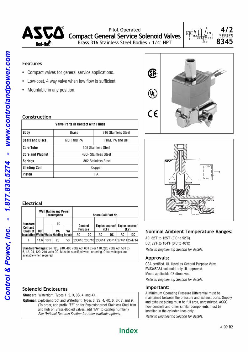
Features
• Compact valves for general service applications.
• Lowcost, 4 way valve when low flow is sufficient.
• Mountable in any position.
4.09 R2
Pilot Operated
Compact General Service Solenoid ValvesBrass 316 Stainless Steel Bodies • 1/4" NPT
BE
A
P
EA
B 4/2SERIES
8345
Solenoid Enclosures
Electrical
Nominal Ambient Temperature Ranges:
AC: 32˚F to 125˚F (0˚C to 52˚C)
DC: 32˚F to 104˚F (0˚C to 40˚C)
Refer to Engineering Section for details.
Approvals:CSA certified. UL listed as General Purpose Valve.
EV8345G81 solenoid only UL approved.
Meets applicable CE directives.
Refer to Engineering Section for details.
Important:A Minimum Operating Pressure Differential must be maintained between the pressure and exhaust ports. Supplyand exhaust piping must be full area, unrestricted. ASCOflow controls and other similar components must beinstalled in the cylinder lines only.
Refer to Engineering Section for details.
Construction
Standard: Watertight, Types 1, 2, 3, 3S, 4, and 4X.
Optional: Explosionproof and Watertight, Types 3, 3S, 4, 4X, 6, 6P, 7, and 9. (To order, add prefix “EF” or, for Explosionproof Stainless Steel trimand hub on BrassBodied valves, add “EV” to catalog number.) See Optional Features Section for other available options.
StandardCoil andClass ofInsulation
Watt Rating and PowerConsumption Spare Coil Part No.
DCWatts
ACGeneralPurpose
Explosionproof(EF)
Explosionproof(EV)
WattsVA
HoldingVA
Inrush AC DC AC DC AC DC
F 11.6 10.1 25 50 238610 238710 238614 238714 274614 274714
Standard Voltages: 24, 120, 240, 480 volts AC, 60 Hz (or 110, 220 volts AC, 50 Hz). 6, 12, 24, 120, 240 volts DC. Must be specified when ordering. Other voltages are available when required.
Valve Parts in Contact with Fluids
Body Brass 316 Stainless Steel
Seals and Discs NBR and PA FKM, PA and UR
Core Tube 305 Stainless Steel
Core and Plugnut 430F Stainless Steel
Springs 302 Stainless Steel
Shading Coil Copper
Piston PA
%
^
)
4qwer
Index
Co
ntr
ol
& P
ow
er,
In
c.
-
1.8
77.8
35.5
274
-
ww
w.c
on
tro
lan
dp
ow
er.
co
m
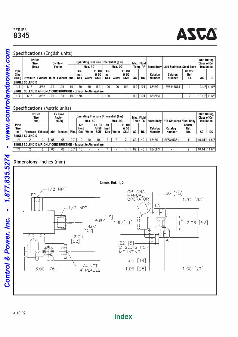
Specifications (Metric units)
Specifications (English units)
4SERIES
8345
4.10 R2
Pipe Size (ins.)
OrificeSize(ins.)
Cv Flow Factor
Operating Pressure Differential (psi) Max. FluidTemp. ˚F Brass Body 316 Stainless Steel Body
Watt Rating/Class of CoilInsulation
Min.
Max. AC Max. DC
Pressure Exhaust Inlet Exhaust
Air-InertGas Water
Lt. Oil@ 50SSU
Air-InertGas Water
Lt. Oil@ 50SSU AC DC
CatalogNumber
CatalogNumber
Constr.Ref.No. AC DC
SINGLE SOLENOID
1/4 1/16 3/32 .09 .09 10 150 150 150 100 100 100 180 104 8345G1 EV8345G81 1 10.1/F 11.6/F
SINGLE SOLENOID AIR-ONLY CONSTRUCTION - Exhaust to Atmosphere
1/4 1/16 3/32 .09 .09 10 150 100 180 104 8345H3 2 10.1/F 11.6/F
Pipe Size (ins.)
Orifice Size (mm)
Kv Flow Factor (m3/h)
Operating Pressure Differential (bar) Max. FluidTemp. ˚C Brass Body 316 Stainless Steel Body
Watt Rating/Class of CoilInsulation
Min.
Max. AC Max. DC
Pressure Exhaust Inlet Exhaust
Air-InertGas Water
Lt. Oil@ 50SSU
Air-InertGas Water
Lt. Oil@ 50SSU AC DC
CatalogNumber
CatalogNumber
Constr.Ref.No. AC DC
SINGLE SOLENOID 1/4 2 2 .08 .08 0.7 10 10 10 7 7 7 82 40 8345G1 EV8345G81 1 10.1/F 11.6/F
SINGLE SOLENOID AIR-ONLY CONSTRUCTION - Exhaust to Atmosphere
1/4 2 2 .08 .08 0.7 10 7 82 40 8345H3 2 10.1/F 11.6/F
Dimensions: inches (mm)
Constr. Ref. 1, 2
Index
Co
ntr
ol
& P
ow
er,
In
c.
-
1.8
77.8
35.5
274
-
ww
w.c
on
tro
lan
dp
ow
er.
co
m
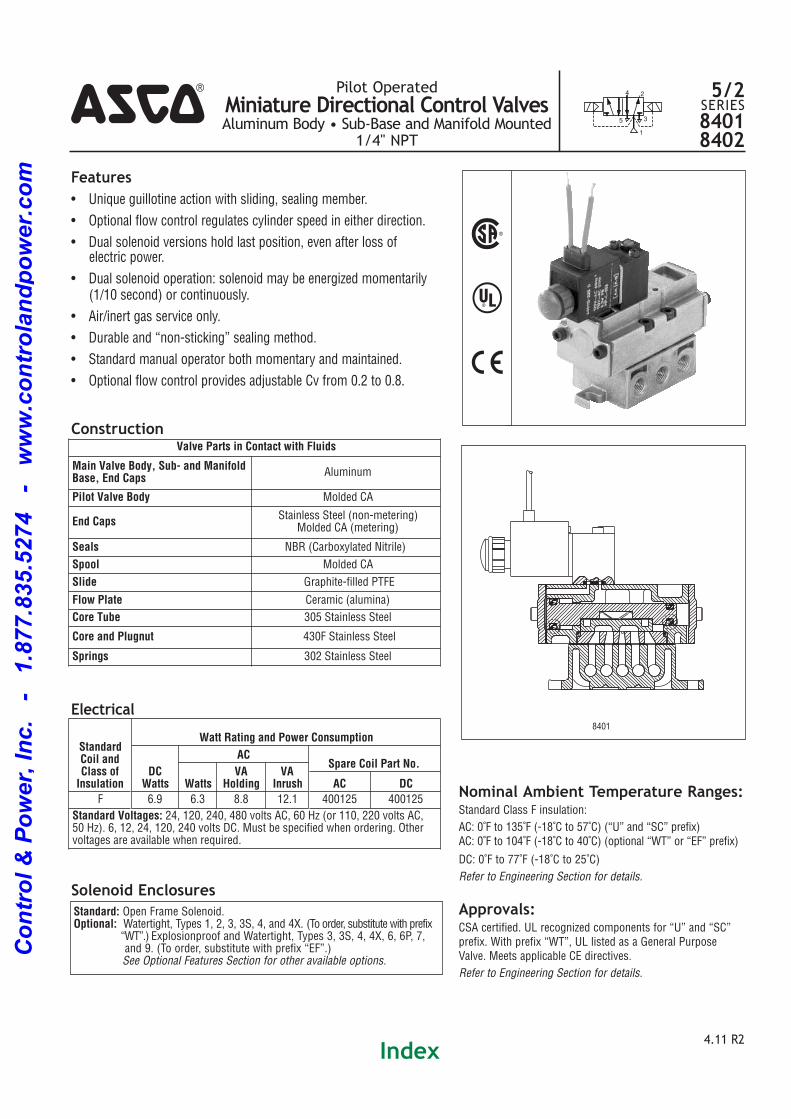
Features• Unique guillotine action with sliding, sealing member.
• Optional flow control regulates cylinder speed in either direction.
• Dual solenoid versions hold last position, even after loss ofelectric power.
• Dual solenoid operation: solenoid may be energized momentarily(1/10 second) or continuously.
• Air/inert gas service only.
• Durable and “nonsticking” sealing method.
• Standard manual operator both momentary and maintained.
• Optional flow control provides adjustable Cv from 0.2 to 0.8.
4.11 R2
Pilot OperatedMiniature Directional Control ValvesAluminum Body • Sub-Base and Manifold Mounted
1/4" NPT5
1
3
24 5/2SERIES84018402
Solenoid Enclosures
Electrical
Nominal Ambient Temperature Ranges:Standard Class F insulation:
AC: 0˚F to 135˚F (18˚C to 57˚C) (“U” and “SC” prefix)AC: 0˚F to 104˚F (18˚C to 40˚C) (optional “WT” or “EF” prefix)
DC: 0˚F to 77˚F (18˚C to 25˚C)
Refer to Engineering Section for details.
Approvals:CSA certified. UL recognized components for “U” and “SC”prefix. With prefix “WT”, UL listed as a General PurposeValve. Meets applicable CE directives.
Refer to Engineering Section for details.
Construction
Standard: Open Frame Solenoid.Optional: Watertight, Types 1, 2, 3, 3S, 4, and 4X. (To order, substitute with prefix
“WT”.) Explosionproof and Watertight, Types 3, 3S, 4, 4X, 6, 6P, 7, and 9. (To order, substitute with prefix “EF”.) See Optional Features Section for other available options.
StandardCoil andClass ofInsulation
Watt Rating and Power Consumption
DCWatts
ACSpare Coil Part No.
WattsVA
HoldingVA
Inrush AC DC
F 6.9 6.3 8.8 12.1 400125 400125
Standard Voltages: 24, 120, 240, 480 volts AC, 60 Hz (or 110, 220 volts AC, 50 Hz). 6, 12, 24, 120, 240 volts DC. Must be specified when ordering. Other voltages are available when required.
Valve Parts in Contact with Fluids
Main Valve Body, Sub- and ManifoldBase, End Caps Aluminum
Pilot Valve Body Molded CA
End Caps Stainless Steel (nonmetering)Molded CA (metering)
Seals NBR (Carboxylated Nitrile)
Spool Molded CA
Slide Graphitefilled PTFE
Flow Plate Ceramic (alumina)
Core Tube 305 Stainless Steel
Core and Plugnut 430F Stainless Steel
Springs 302 Stainless Steel
8401
%
^
)
4
Index
Co
ntr
ol
& P
ow
er,
In
c.
-
1.8
77.8
35.5
274
-
ww
w.c
on
tro
lan
dp
ow
er.
co
m
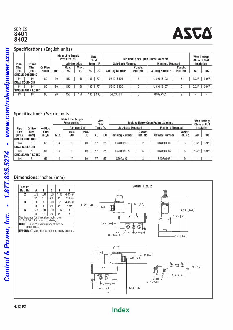
Specifications (Metric units)
Specifications (English units)
4SERIES84018402
4.12 R2
PipeSize(ins.)
OrificeSize(ins.)
Cv FlowFactor
Main Line Supply Pressure (psi)
Max.Fluid
Temp. ˚F
Molded Epoxy Open Frame SolenoidWatt Rating/Class of CoilInsulation
Min.
Air-Inert Gas Sub-Base Mounted Manifold MountedMax.AC
Max .DC AC DC Catalog Number
Constr.Ref. No. Catalog Number
Constr.Ref. No. AC DC
SINGLE SOLENOID 1/4 1/4 .80 20 150 150 135 77 U8401B101 2 U8401B103 3 6.3/F 6.9/F
DUAL SOLENOID 1/4 1/4 .80 20 150 150 135 77 U8401B105 5 U8401B107 6 6.3/F 6.9/F
SINGLE AIR PILOTED 1/4 1/4 .80 20 150 150 135 135 8402A101 8 8402A103 9
Pipe Size (ins.)
Orifice Size (mm)
Kv FlowFactor(m3/h)
Main Line Supply Pressure (bar)
Max.Fluid
Temp.˚C
Molded Epoxy Open Frame SolenoidWatt Rating/Class of CoilInsulation
Min.
Air-Inert Gas Sub-Base Mounted Manifold Mounted
Max.AC
Max.DC AC DC Catalog Number
Constr.Ref. No. Catalog Number
Constr.Ref. No. AC DC
SINGLE SOLENOID 1/4 6 .69 1.4 10 10 57 25 U8401B101 2 U8401B103 3 6.3/F 6.9/F
DUAL SOLENOID 1/4 6 .69 1.4 10 10 57 25 U8401B105 5 U8401B107 6 6.3/F 6.9/F
SINGLE AIR PILOTED 1/4 6 .69 1.4 10 10 57 57 8402A101 8 8402A103 9
Dimensions: inches (mm)Constr.Ref. No. A B C E F
2 .73 .60 .80 1.02 4.43 �
19 15 20 26 112 �
3 X X .79 .91 4.43 �
X X 20 23 112
5 .73 .60 .80 1.02 X
19 15 20 26 XSee drawings for dimensions not shown. � Add .54 (13.7 mm) for metering.
Note: "EF" and "WT" dimensions shown by dotted lines.
IMPORTANT: Valve can be mounted in any position.
Constr. Ref. 2
Index
Co
ntr
ol
& P
ow
er,
In
c.
-
1.8
77.8
35.5
274
-
ww
w.c
on
tro
lan
dp
ow
er.
co
m

4
4.13 R2
SERIES84018402
Constr. Ref. 5
Constr. Ref. 3(Valve only)
Constr. Ref. 3(Valve with required end brackets.)
(See List Price Schedule for appropriate kit numbers.)
Dimensions: inches (mm)
Index
Co
ntr
ol
& P
ow
er,
In
c.
-
1.8
77.8
35.5
274
-
ww
w.c
on
tro
lan
dp
ow
er.
co
m
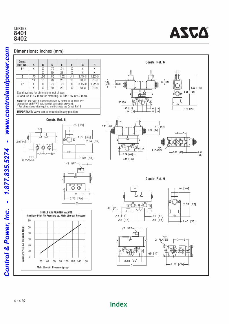
4.14 R2
4SERIES84018402
Constr. Ref. 6
Constr. Ref. 9
Constr. Ref. 8
Dimensions: inches (mm)
SINGLE AIR PILOTED VALVESAuxiliary Pilot Air Pressure vs. Main Line Air Pressure
Auxiliary Pilot Air Pressure (psig)
Main Line Air Pressure (psig)
0
20
10080604020 120 140 160
40
60
80
100
120
Const.Ref. No. A B C E F G H
6* X X .79 .91 X X X
X 20 23 X X X
8 .73 .60 .80 1.02 .41 3.45 1.22 �
19 15 20 26 10 88 31 �
9* X X .79 .91 X 3.45 1.22 �
X X 20 23 X 88 31 �
See drawings for dimensions not shown. � Add .54 (13.7 mm) for metering. Add 1.07 (27.2 mm).
Note: "EF" and "WT" dimensions shown by dotted lines. Male 1/2" connection on EF/WT coil, conduit connector provided. * For dimensions with required end brackets see Const. Ref. 3
IMPORTANT: Valve can be mounted in any position.
Index
Co
ntr
ol
& P
ow
er,
In
c.
-
1.8
77.8
35.5
274
-
ww
w.c
on
tro
lan
dp
ow
er.
co
m

NOTE: When mounting inline 8551 valves with WT & EF solenoids (6.3 & 6.9 watts), ASCO recommends using two(2) 1/8” thick washers under the valve body to provide clearance for the solenoid coil.
Solenoid Enclosures
Approvals:SC: UL recognized component.
EF: UL and CSA solenoid approval.WT: UL General Purpose valve.Meets applicable CE directives. Refer to Engineering
Section for details.
Construction
Electrical
Nominal Ambient Temperature Ranges:SC: AC/DC: 5˚F to +140˚F (15˚C to 60˚C)
EF: AC: 5˚F to +104˚F (15˚C to 40˚C)
DC: 5˚F to +77˚F (15˚C to 25˚C)
WT: AC: 5˚F to +140˚F (15˚C to 60˚C)
DC: 5˚F to +77˚F (15˚C to 25˚C)
Note: For temperatures below 32˚F (0˚C) moisturefree air
must be used. Refer to Engineering Section for details.
4Features• Compact spool valve with threaded port connections.
• All exhaust ports are pipable, providing better protection
against harsh environments.
• Standard manual operator.
• DIN, Watertight and Explosionproof solenoids available.
• Single and dual solenoid constructions.
• Mountable in any position.
Standard: - PrefixSC = IP65 type DIN (open frame) per 46244WT= Combination General Purpose and Watertight Types 1, 2, 3, 3S, 4, and 4X EF = Combination Explosionproof and Watertight Types 3, 3S, 4, 4X, 6, 6P, 7, 9
CLASS 1, DIV. 1 (Groups A D) and CLASS 2, DIV.1 Type 9 (Groups EG)
Option:Metering: order metering device pkg. of 20 pcs. Order kit number: 276790002*.
3/2 5/2
122 4
14
53
1
2
3
1
122 4
53
1
1
2
3
% ^ )
Valve Parts in Contact with Fluid
Body Black Anodized Aluminum
Spring Phosphate treated black steel
Shading Coil Copper
Seals NBR + PUR
Core and Core tube Stainless Steel/Brass
End Covers 6/6 glass filled PA/FG
Spool Aluminum
Internal Parts Zamak, Steel, CA, Aluminum
Standard Coiland Class of Insulation
EnclosureType
Watt Rating and Power Consumption
Spare Coil Part Number
DCWatts
ACWatts
VAHolding
VAInrush AC DC
F SC 3 2.5 3.5 6 400125 400125
F EF 6.9 6.3 7 10.1 266762 270007
F WT 6.9 6.3 7 10.1 266763 270008
Standard Voltages: SC: 24, 120, 240 volts AC, 5060 Hz; 12, 24, 120 volts DC. WT and EF: 24/5060Hz, (120/60, 110120/50)�, (240/60, 220240/50) volts AC; 6, 12, 24, 120 volts DC.Notes: � Order as 120/60, 110/50
Order as 240/60, 220/50
Pilot OperatedSpool Valves
Anodized Aluminum Bodies • 1/4” NPT
3/25/2SERIES8551
4.145 R1Index
Co
ntr
ol
& P
ow
er,
In
c.
-
1.8
77.8
35.5
274
-
ww
w.c
on
tro
lan
dp
ow
er.
co
m
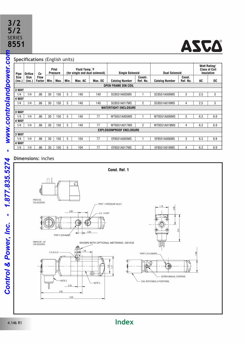
Specifications (English units)4
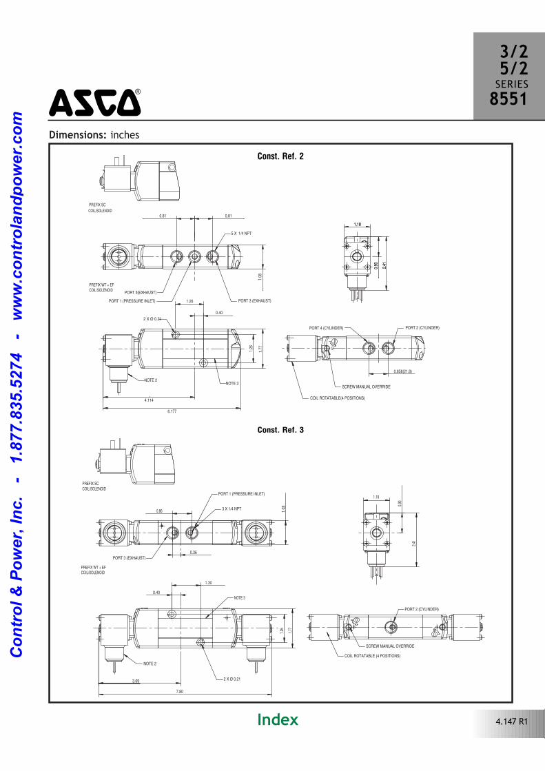
Dimensions: inches
0.86
1.77
1.O
8
1.26
0.40
1.30
0.36
3.69
1.18
2.41
0.90
5.69
2 X Ø 0.21
PREFIX WT + EFCOIL/SOLENOID
PREFIX SCCOIL/SOLENOID
NOTE 3NOTE 2
SCREW MANUAL OVERRIDE
COIL ROTATABLE (4 POSITIONS)
PORT 2 (CYLINDER)
3 X 1/4 NPT
PORT 1 (PRESSURE INLET)
PORT 3 (EXHAUST)
SHOWN WITH OPTIONAL METERING DEVICE
Const. Ref. 1
PipeSize(ins.)
OrificeSize(ins.)
CvFlowFactor
PilotPressure
Fluid Temp.˚F (for single and dual solenoid) Single Solenoid Dual Solenoid
Watt Rating/ Class of CoilInsulation
Min. Max. Min. Max. AC Max. DC Catalog NumberConstr.Ref. No. Catalog Number
Const.Ref. No. AC DC
OPEN FRAME DIN COIL
3 WAY
1/4 1/4 .86 30 150 5 140 140 SC8551A005MS 1 SC8551A006MS 3 2.5 3
4 WAY
1/4 1/4 .86 30 150 5 140 140 SC8551A017MS 2 SC8551A018MS 4 2.5 3
WATERTIGHT ENCLOSURE
3 WAY
1/4 1/4 .86 30 150 5 140 77 WT8551A005MS 1 WT8551A006MS 3 6.3 6.9
4 WAY
1/4 1/4 .86 30 150 5 140 77 WT8551A017MS 2 WT8551A018MS 4 6.3 6.9
EXPLOSIONPROOF ENCLOSURE
3 WAY
1/4 1/4 .86 30 150 5 104 77 EF8551A005MS 1 EF8551A006MS 3 6.3 6.9
4 WAY
1/4 1/4 .86 30 150 5 104 77 EF8551A017MS 2 EF8551A018MS 4 6.3 6.9
3/25/2SERIES8551
4.146 R1 Index
Co
ntr
ol
& P
ow
er,
In
c.
-
1.8
77.8
35.5
274
-
ww
w.c
on
tro
lan
dp
ow
er.
co
m
Dimensions: inches
20.520.5
21.8
4527
.5
32
10.25
104.5
30
22.8
61.3
6.177
2xÿ 0.209(ÿ5.3)5.3
32
0.81 0.81
2 X Ø 0.21
1.26
0.40
4.114
1.26
1.77
1.181.18
0.90
0.90
2.41
2.41
PREFIX WT + EFCOIL/SOLENOID
0.858(21.8)
1.08
NOTE 2NOTE 3
SCREW MANUAL OVERRIDE
COIL ROTATABLE(4 POSITIONS)
PORT 4 (CYLINDER) PORT 2 (CYLINDER)
5 X 1/4 NPT
PORT 5(EXHAUST)
PORT 1 (PRESSURE INLET) PORT 3 (EXHAUST)
PREFIX SC
COIL/SOLENOID
Const. Ref. 2
3/25/2SERIES85514
0.86
1.77
1.26
0.40
1.30
3.69
7.80
1.08
1.18
0.90
2.41
0.36
PREFIX SCCOIL/SOLENOID
PREFIX WT + EFCOIL/SOLENOID
2 X Ø 0.21
NOTE 2
NOTE 3
COIL ROTATABLE (4 POSITIONS)
SCREW MANUAL OVERRIDE
PORT 2 (CYLINDER)
3 X 1/4 NPT
PORT 1 (PRESSURE INLET)
PORT 3 (EXHAUST)
Const. Ref. 3
4.147 R1Index
Co
ntr
ol
& P
ow
er,
In
c.
-
1.8
77.8
35.5
274
-
ww
w.c
on
tro
lan
dp
ow
er.
co
m
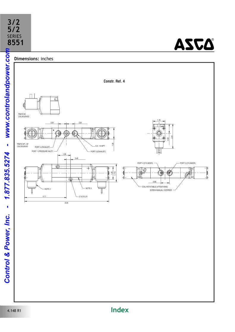
Constr. Ref. 4
0.81 0.81
0.86
1.77
2
1.26
1.26
0.40
8.28
4.11
1.08
1.18
2.41
0.90
PREFIX SCCOIL/SOLENOID
PREFIX WT + EFCOIL/SOLENOID
2 X Ø 0.21
NOTE 2 NOTE 3COIL ROTATABLE (4 POSITIONS)
SCREW MANUAL OVERRIDE
PORT 2 (CYLINDER)PORT 4 (CYLINDER)
5 X 1/4 NPTPORT 5 (EXHAUST)
PORT 1 (PRESSURE INLET) PORT 3 (EXHAUST)
Dimensions: inches 4
3/25/2SERIES8551
4.148 R1 Index
Co
ntr
ol
& P
ow
er,
In
c.
-
1.8
77.8
35.5
274
-
ww
w.c
on
tro
lan
dp
ow
er.
co
m

%
^
)
Features
• Unique sealing technology combines hard Tseals and
flexible orings for bubble tight shutoff, dirt resistance, and
multimillion cycle life.
• Designed for use in corrosive atmospheres.
• Single or dual solenoids.
• Mountable in any position.
• Dual solenoid operation: solenoid may be energized
momentarily (1/10 second) or continuously.
• Low Power and Intrinsically Safe constructions are avaiable.
See Special Service Valve Section for details.
4.15
Single or Dual Solenoid • Pilot Operated
Stainless Steel ValvesFor In-line Applications • 1/4" NPT
4 2
5 1 3
4 2
5 1 3
5/2SERIES
8551
Solenoid Enclosures
Electrical
Nominal Ambient Temperature Ranges:AC: 4˚F to 125˚F (20˚C to 52˚C)
DC: 4˚F to 104˚F (20˚C to 40˚C)
Refer to Engineering Section for details.
Approvals:UL listed for General Purpose valve.UL recognized components for “SC” prefix (open frame version).
Meets applicable CE directives. Optional "EV" solenoid is CSAcertified and UL listed.
Refer to Engineering Section for details.
Construction
Standard: Watertight, Types 1, 2, 3, 3S, 4, and 4X.
Optional: Explosionproof and Watertight, Types 3, 3S, 4, 4X, 6, 6P, 7, and 9.(For Stainless Steel trim and conduit hub, add prefix “EV” to catalog number.)See Optional Features Section for other available options.
Valve Parts in Contact with Fluids
Body 316 Stainless Steel
Seals and Discs NBR and PUR
Core and Plugnut 430F Stainless Steel
Core Tube 305 Stainless Steel
Springs 302 Stainless Steel
Shading Coil Copper
End Covers 316 Stainless Steel
Spool 316 Stainless Steel
Internal Parts Zamak, Steel, CA, Brass
StandardCoil andClass of Insulation
Watt Rating and PowerConsumption Spare Coil Part No.
DCWatts
AC GeneralPurpose
Explosionproof(EV)
WattsVA
HoldingVA
Inrush AC DC AC DC
F 11.6 10.1 25 50 238610 238710 274614 274714
Standard Voltages: 24, 120, 240, 480 volts AC, 60 Hz (115 230 volts AC, 50Hz). 6, 12, 24, 120, 240 volts DC. Must be specified when ordering. Othervoltages available when required.
SingleSolenoid
DualSolenoid
4qwer
Index
Co
ntr
ol
& P
ow
er,
In
c.
-
1.8
77.8
35.5
274
-
ww
w.c
on
tro
lan
dp
ow
er.
co
m

Specifications (Metric units)
Specifications (English units)
4SERIES
8551
4.16
PipeSize(ins.)
OrificeSize(ins.)
Cv FlowFactor
Single Solenoid Dual Solenoid
Watt Rating/Class of Coil Insulation
OperatingPressure
Differential (psi) Max.Fluid
Temp. ˚F Stainless Steel Constr. Ref. No.
OperatingPressure
Differential (psi) Max.Fluid
Temp. ˚F Stainless Steel Constr.Ref.No.Min.
Max.
Min.
Max.
AC DC AC DC Catalog Number AC DC AC DC Catalog Number AC DC
1/4 1/4 .84 35 150 120 140 120 8551G453 1 20 150 120 140 120 8551G455 2 10.1/F 11.6/F
PipeSize(ins.)
OrificeSize(mm)
Kv FlowFactor(m3/h)
Single Solenoid Dual Solenoid
Watt Rating/Class of Coil Insulation
OperatingPressure
Differential (bar) Max.Fluid
Temp. ˚C Stainless Steel Constr. Ref. No.
OperatingPressure
Differential (bar) Max.Fluid
Temp. ˚C Stainless Steel Constr.Ref.No.Min.
Max.
Min.
Max.
AC DC AC DC Catalog Number AC DC AC DC Catalog Number AC DC
1/4 6 .72 2 10 8 59 48 8551G453 1 1 10 8 59 48 8551G455 2 10.1/F 11.6/F
Dimensions: inches (mm)
SINGLE SOLENOID Constr. Ref. 1
DUAL SOLENOID Constr. Ref. 2
Index
Co
ntr
ol
& P
ow
er,
In
c.
-
1.8
77.8
35.5
274
-
ww
w.c
on
tro
lan
dp
ow
er.
co
m


![[REPUBLIC ACT 8551] - Philippine Commission on Women · Section 12 of Republic Act No. 6975 is hereby amended to read as follows: ... Republic Act 8551 “In times of national emergency,](https://img.pdfslide.net/doc/110x75/5ae56cc17f8b9ae1578c4877/republic-act-8551-philippine-commission-on-12-of-republic-act-no-6975-is-hereby.jpg)