Embed Size (px)
Citation preview
86Duino www.86duino.com
-1-
Control Robotics Arm with EduCake
1. About Robotics Arm
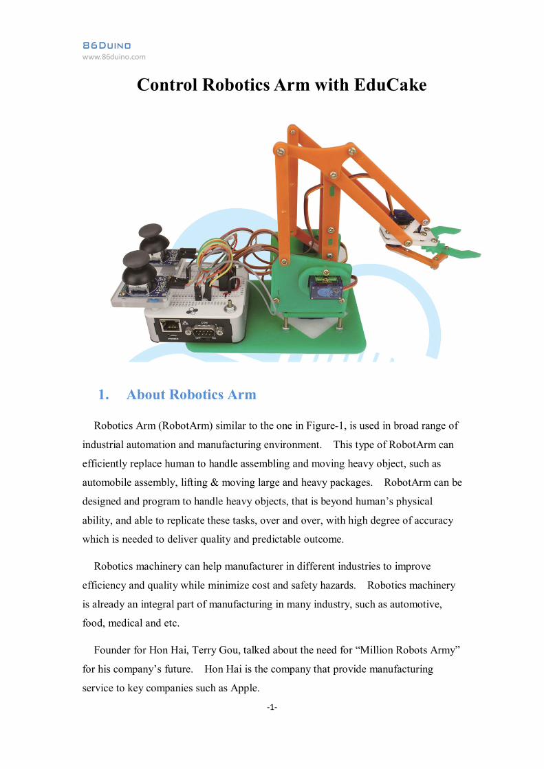
Robotics Arm (RobotArm) similar to the one in Figure-1, is used in broad range of
industrial automation and manufacturing environment. This type of RobotArm can
efficiently replace human to handle assembling and moving heavy object, such as
automobile assembly, lifting & moving large and heavy packages. RobotArm can be
designed and program to handle heavy objects, that is beyond human’s physical
ability, and able to replicate these tasks, over and over, with high degree of accuracy
which is needed to deliver quality and predictable outcome.
Robotics machinery can help manufacturer in different industries to improve
efficiency and quality while minimize cost and safety hazards. Robotics machinery
is already an integral part of manufacturing in many industry, such as automotive,
food, medical and etc.
Founder for Hon Hai, Terry Gou, talked about the need for “Million Robots Army”
for his company’s future. Hon Hai is the company that provide manufacturing
service to key companies such as Apple.
86Duino www.86duino.com
-2-
Figure-1. Robotics Arm from Kuka, http://www.kuka-robotics.com
86Duino www.86duino.com
-3-
2. Robotics Arm Structure
RobotArm devices for commercial application in industrial-automation and
manufacturing are complex and high cost. In addition to the mechanical structure
that provides the core function (torch, welding, spray paint, vacuum pickup, magnetic
pickup and etc.), there are other motors, servos, hydraulic and electronic components
that make up the RobotArm. In order for the RobotArm to function as intended,
there are PLC controller, different type of intelligent sensors, computerized
monitoring system, alarm system, user interface to interact and operate the system,
and other components needed for the system to function. To operate commercial
RobotArm efficiently and in a safe manner, workers have to go through training to
learn how to use and interact with RobotArm. It’s a complex and high cost
environment to integrate different components that make up the RobotArm solution
for commercial use.
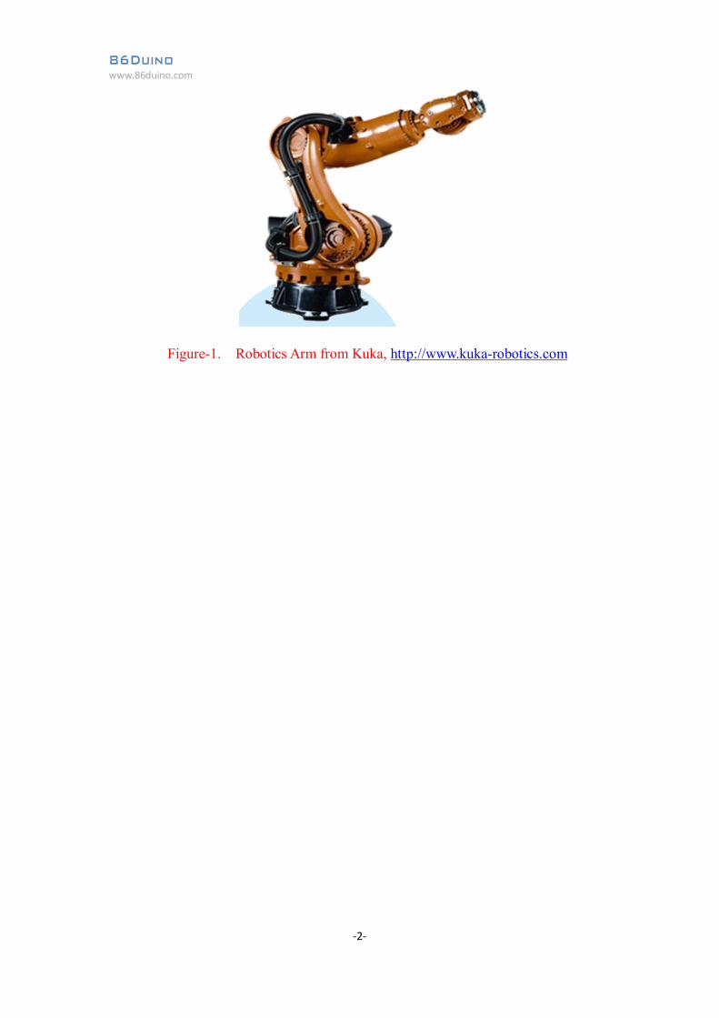
For this application note, we will use a simple implementation to lean basic
RobotArm functions, as shown in Figure-2, using a simple mechanical design with
low-cost components that can easily be purchased from the DIY/hobbyist
marketplace.
Figure-2. Robotics Arm common in the DIY Hobbyist market
Simple RobotArm design, like the one in Figure-2, has been around for more than
10 years. By controlling movement around different axis, the continuous
86Duino www.86duino.com
-4-
development in the market created countless derivative from this basic design with
different function to serve different objectives. Within the academic community,
most of the experiment and teaching contents that involve RobotArm are based on
similar design as the one in Figure-2, controlling anywhere from 2 to 10 axis. In
recent year, starting around 2013, due to the enhanced communication and access to
large pool of shared information, there are significant improvement and new
development around RobotArm, especially in the DIY and hobbyist market, such as
the uARM which successfully raised over $250K dollars via a Kickstarter project.
https://www.kickstarter.com/projects/ufactory/uarm-put-a-miniature-industrial-robo
t-arm-on-your
The uARM’s success, along with the project’s open-source nature which enable
others to access the hardware and software design files, triggered multiple similar
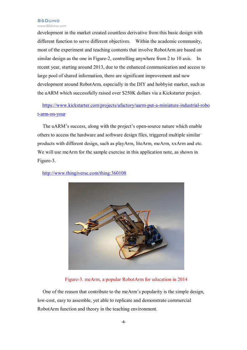
products with different design, such as playArm, liteArm, meArm, xxArm and etc.
We will use meArm for the sample exercise in this application note, as shown in
Figure-3.
http://www.thingiverse.com/thing:360108
Figure-3. meArm, a popular RobotArm for education in 2014
One of the reason that contribute to the meArm’s popularity is the simple design,
low-cost, easy to assemble, yet able to replicate and demonstrate commercial
RobotArm function and theory in the teaching environment.

86Duino www.86duino.com
-5-
3. Building the meArm Robotics Arm
The meArm RobotArm consists of the mechanical structure, servo, electronic
control circuit, power supply and application code. There are mechanical design
files for meArm share by numerous developer where you can use acrylic, aluminum
sheet and wood panel, ranging from 2mm to 5mm thickness, and cut out the required
parts manually or with help from a laser cutter, as shown in Figure-4.
Figure-4. Mechanical component for meArm, laser cut from acrylic panel.
The mechanical parts design in Figure-4 above is based on 3mm panel. When
using panel with different thickness, some of the join may not fit well and the length
of the screws used to hold different pieces of the panel in place may be different and
require adjustment and modification to complete the assembly.
For the exercise in this section, we use a SG90 servo motor. In an earlier
application note, PWM Tutorial (Chapter-3), we talked about the SG90 servo along
with servo control in great details. Please refer to this application note for additional
information not covered here.
Many of the lower cost servo motors are built with larger tolerance in term of the
servo’s mechanical size, where the servo housing’s dimension can vary as much as
1mm, which can be a source of problem in building any robotics devices that require
86Duino www.86duino.com
-6-
precise mechanical fitting to properly assemble each device for the device to function
properly. To correct the mechanical misalignment caused by the variation in the
servo’s housing, you may need to loosen the mounting bracket to accommodate
slightly oversized servo housing or insert a spacer, to fill the space to support servo
housings that are slightly smaller.
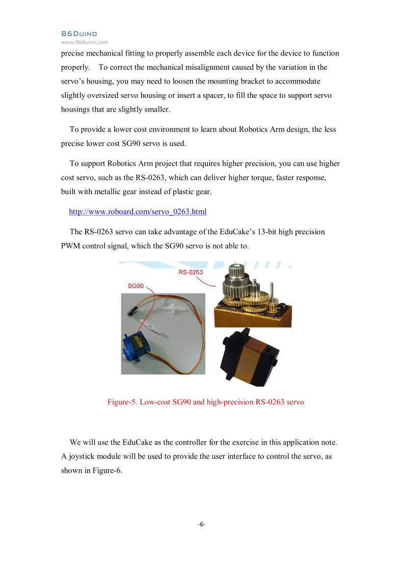
To provide a lower cost environment to learn about Robotics Arm design, the less
precise lower cost SG90 servo is used.
To support Robotics Arm project that requires higher precision, you can use higher
cost servo, such as the RS-0263, which can deliver higher torque, faster response,
built with metallic gear instead of plastic gear.
http://www.roboard.com/servo_0263.html
The RS-0263 servo can take advantage of the EduCake’s 13-bit high precision
PWM control signal, which the SG90 servo is not able to.
Figure-5. Low-cost SG90 and high-precision RS-0263 servo
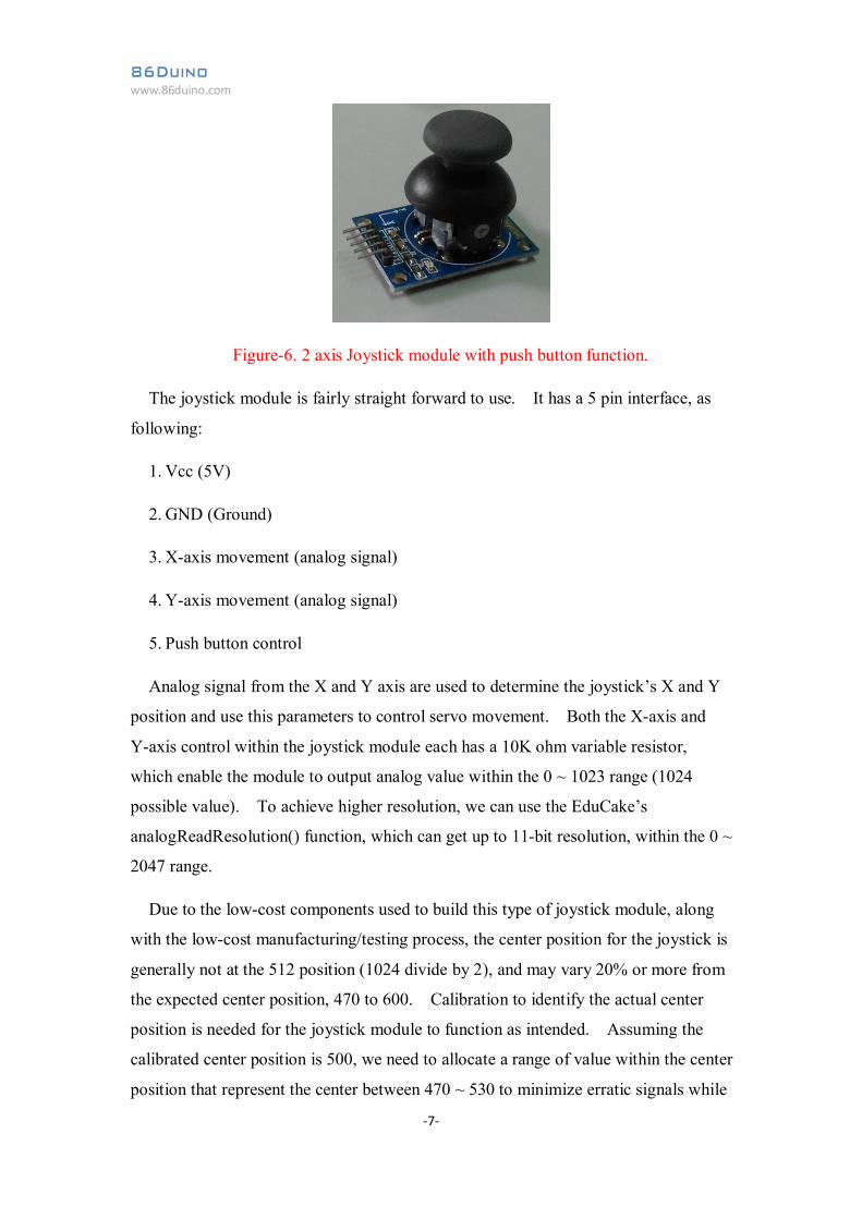
We will use the EduCake as the controller for the exercise in this application note.
A joystick module will be used to provide the user interface to control the servo, as
shown in Figure-6.
86Duino www.86duino.com
-7-
Figure-6. 2 axis Joystick module with push button function.
The joystick module is fairly straight forward to use. It has a 5 pin interface, as
following:
1. Vcc (5V)
2. GND (Ground)
3. X-axis movement (analog signal)
4. Y-axis movement (analog signal)
5. Push button control
Analog signal from the X and Y axis are used to determine the joystick’s X and Y
position and use this parameters to control servo movement. Both the X-axis and
Y-axis control within the joystick module each has a 10K ohm variable resistor,
which enable the module to output analog value within the 0 ~ 1023 range (1024
possible value). To achieve higher resolution, we can use the EduCake’s
analogReadResolution() function, which can get up to 11-bit resolution, within the 0 ~
2047 range.
Due to the low-cost components used to build this type of joystick module, along
with the low-cost manufacturing/testing process, the center position for the joystick is
generally not at the 512 position (1024 divide by 2), and may vary 20% or more from
the expected center position, 470 to 600. Calibration to identify the actual center
position is needed for the joystick module to function as intended. Assuming the
calibrated center position is 500, we need to allocate a range of value within the center
position that represent the center between 470 ~ 530 to minimize erratic signals while
86Duino www.86duino.com
-8-
the joystick is at the center position, where the application code treat the 470 ~ 530
range as the center position.
The push button control is built-in to the joystick control, by pressing on the
joystick to momentary activate the push button. When pressing the joystick to
activate the push button, it’s difficult to maintain the joystick’s position and cause
un-intended movement and change the joystick position. For application with
sensitive joystick control, it’s not a good practice to implement push button as part of
the joystick and should design the push button control as a separate mechanical
interface.
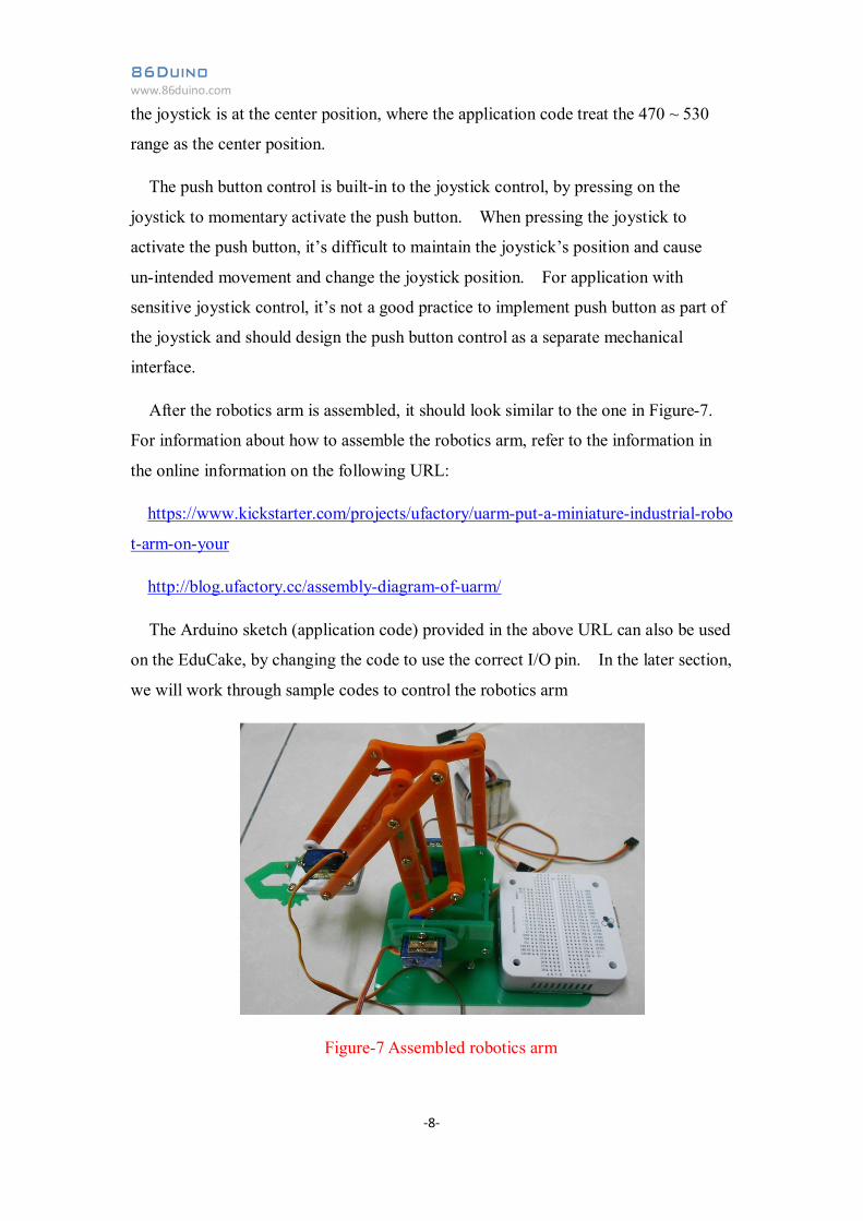
After the robotics arm is assembled, it should look similar to the one in Figure-7.
For information about how to assemble the robotics arm, refer to the information in
the online information on the following URL:
https://www.kickstarter.com/projects/ufactory/uarm-put-a-miniature-industrial-robo
t-arm-on-your
http://blog.ufactory.cc/assembly-diagram-of-uarm/
The Arduino sketch (application code) provided in the above URL can also be used
on the EduCake, by changing the code to use the correct I/O pin. In the later section,
we will work through sample codes to control the robotics arm
Figure-7 Assembled robotics arm
86Duino www.86duino.com
-9-
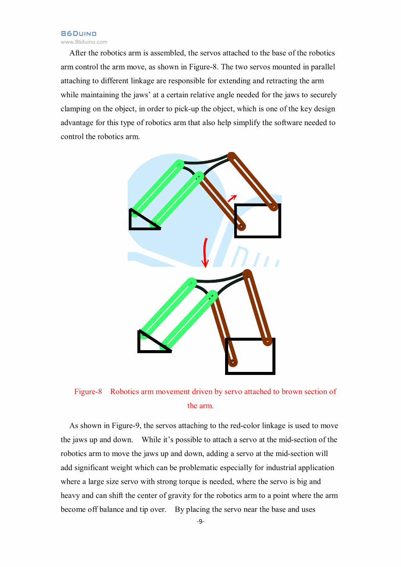
After the robotics arm is assembled, the servos attached to the base of the robotics
arm control the arm move, as shown in Figure-8. The two servos mounted in parallel
attaching to different linkage are responsible for extending and retracting the arm
while maintaining the jaws’ at a certain relative angle needed for the jaws to securely
clamping on the object, in order to pick-up the object, which is one of the key design
advantage for this type of robotics arm that also help simplify the software needed to
control the robotics arm.
Figure-8 Robotics arm movement driven by servo attached to brown section of
the arm.
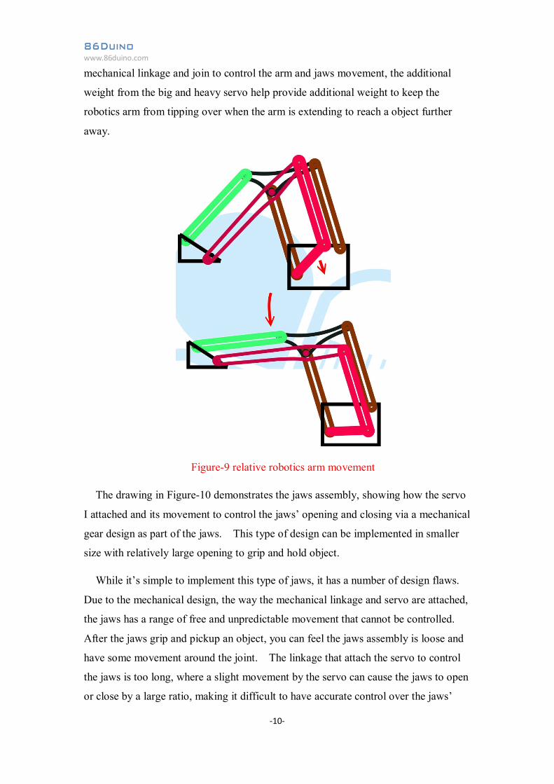
As shown in Figure-9, the servos attaching to the red-color linkage is used to move
the jaws up and down. While it’s possible to attach a servo at the mid-section of the
robotics arm to move the jaws up and down, adding a servo at the mid-section will
add significant weight which can be problematic especially for industrial application
where a large size servo with strong torque is needed, where the servo is big and
heavy and can shift the center of gravity for the robotics arm to a point where the arm
become off balance and tip over. By placing the servo near the base and uses
86Duino www.86duino.com
-10-
mechanical linkage and join to control the arm and jaws movement, the additional
weight from the big and heavy servo help provide additional weight to keep the
robotics arm from tipping over when the arm is extending to reach a object further
away.
Figure-9 relative robotics arm movement
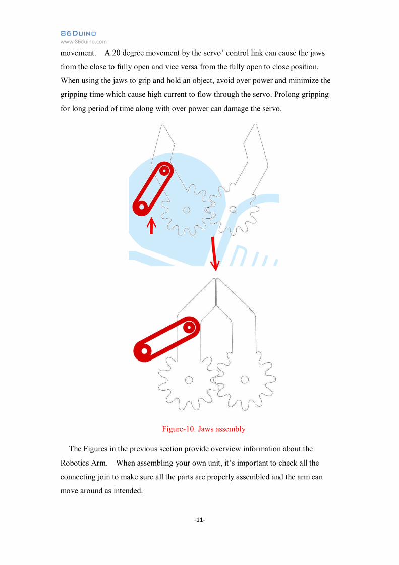
The drawing in Figure-10 demonstrates the jaws assembly, showing how the servo
I attached and its movement to control the jaws’ opening and closing via a mechanical
gear design as part of the jaws. This type of design can be implemented in smaller
size with relatively large opening to grip and hold object.
While it’s simple to implement this type of jaws, it has a number of design flaws.
Due to the mechanical design, the way the mechanical linkage and servo are attached,
the jaws has a range of free and unpredictable movement that cannot be controlled.
After the jaws grip and pickup an object, you can feel the jaws assembly is loose and
have some movement around the joint. The linkage that attach the servo to control
the jaws is too long, where a slight movement by the servo can cause the jaws to open
or close by a large ratio, making it difficult to have accurate control over the jaws’
86Duino www.86duino.com
-11-
movement. A 20 degree movement by the servo’ control link can cause the jaws
from the close to fully open and vice versa from the fully open to close position.
When using the jaws to grip and hold an object, avoid over power and minimize the
gripping time which cause high current to flow through the servo. Prolong gripping
for long period of time along with over power can damage the servo.
Figure-10. Jaws assembly
The Figures in the previous section provide overview information about the
Robotics Arm. When assembling your own unit, it’s important to check all the
connecting join to make sure all the parts are properly assembled and the arm can
move around as intended.
86Duino www.86duino.com
-12-
4. Robotics Arm Control
In the previous section, we talked about the robotics arm’s structure and
assembling the robotics arm using a common design with 4 servos, based on the
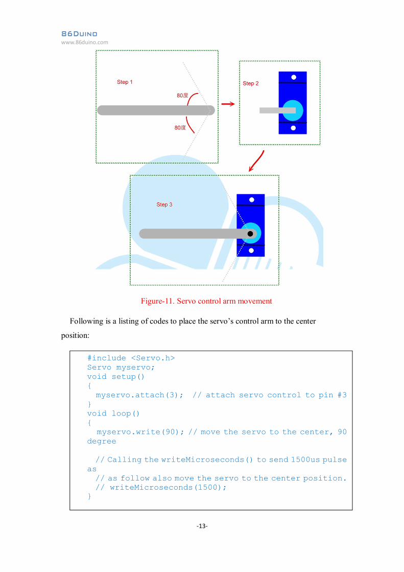
meArm. Since the SG90 servo has limited movement, approximately 80 degree or
less in each direction, as shown in Figure-11, one of the area that need particular
attention is to align and position each servo to yield maximum control over the
robotics arm’s movement as the servo move. In addition, you need to check and
make sure the robotics arm’s mechanical join and assembly can move freely without
interference caused by components that are improperly assembled or misaligned
components that cause fiction and block the other components’ movement.
When working with a new robotics arm design, it’s a good practice to check and
validate the servo is able to control the robotics arm’s as expected, by using a simple
PWM circuitry (refer to the PWM application note for more information) to send a
1.5 ms pulse that put the servo’s control arm to the center position, a 2.0 ms pulse to
turn the servo’s control arm to the right most position and a 1.0 ms pulse to turn the
servo’s control arm to the left most position.
Due to the meArm’s simple design, the robotics arm’s actual movement and
position will be affected by gravity caused by the arm’s weight, as it extend and
retract, which can be tricky to control. A well designed robotics arm would take
these factor as part of the design consideration to achieve more accurate control.
86Duino www.86duino.com
-13-
Figure-11. Servo control arm movement
Following is a listing of codes to place the servo’s control arm to the center
position:
#include <Servo.h> Servo myservo; void setup() { myservo.attach(3); // attach servo control to pin #3 } void loop() { myservo.write(90); // move the servo to the center, 90 degree // Calling the writeMicroseconds() to send 1500us pulse as // as follow also move the servo to the center position. // writeMicroseconds(1500); }
86Duino www.86duino.com
-14-
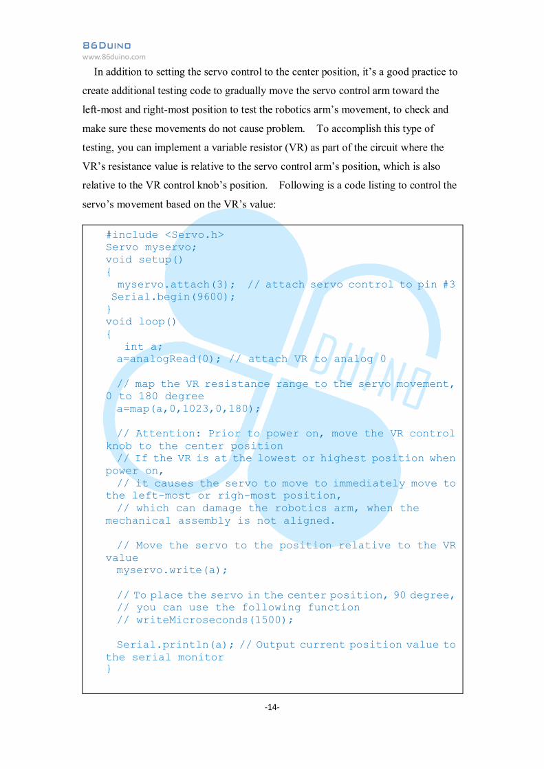
In addition to setting the servo control to the center position, it’s a good practice to
create additional testing code to gradually move the servo control arm toward the
left-most and right-most position to test the robotics arm’s movement, to check and
make sure these movements do not cause problem. To accomplish this type of
testing, you can implement a variable resistor (VR) as part of the circuit where the
VR’s resistance value is relative to the servo control arm’s position, which is also
relative to the VR control knob’s position. Following is a code listing to control the
servo’s movement based on the VR’s value:
#include <Servo.h> Servo myservo; void setup() { myservo.attach(3); // attach servo control to pin #3 Serial.begin(9600); } void loop() { int a; a=analogRead(0); // attach VR to analog 0 // map the VR resistance range to the servo movement, 0 to 180 degree a=map(a,0,1023,0,180); // Attention: Prior to power on, move the VR control knob to the center position // If the VR is at the lowest or highest position when power on, // it causes the servo to move to immediately move to the left-most or righ-most position, // which can damage the robotics arm, when the mechanical assembly is not aligned. // Move the servo to the position relative to the VR value myservo.write(a); // To place the servo in the center position, 90 degree, // you can use the following function // writeMicroseconds(1500); Serial.println(a); // Output current position value to the serial monitor }
86Duino www.86duino.com
-15-
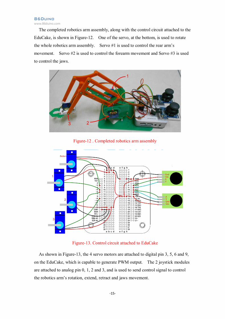
The completed robotics arm assembly, along with the control circuit attached to the
EduCake, is shown in Figure-12. One of the servo, at the bottom, is used to rotate
the whole robotics arm assembly. Servo #1 is used to control the rear arm’s
movement. Servo #2 is used to control the forearm movement and Servo #3 is used
to control the jaws.
Figure-12 . Completed robotics arm assembly
Figure-13. Control circuit attached to EduCake
As shown in Figure-13, the 4 servo motors are attached to digital pin 3, 5, 6 and 9,
on the EduCake, which is capable to generate PWM output. The 2 joystick modules
are attached to analog pin 0, 1, 2 and 3, and is used to send control signal to control
the robotics arm’s rotation, extend, retract and jaws movement.
86Duino www.86duino.com
-16-
5. Controlling the Completed Robotics Arm
The following code listing is to control the completed robotics arm’s movement:
#include <Servo.h> Servo myservo1; // Servo to rotate the robotics arm assembly Servo myservo2; // Servo to control rear arm movement Servo myservo3; // Servo to control forearm movement Servo myservo4; // Servo to control the Jaws assembly void setup() { Serial.begin(9600); myservo1.attach(3); myservo2.attach(5); myservo3.attach(6); myservo4.attach(9); } void loop() { int a,b,c,d,e; // the a, b, c & c variables are used to retrieve value from // analog pin 0, 1, 2 and 3, represent the relative position // for the two joysticks. // The actual values for the center position and ranges to // control the robotics arm movement are different, based // on the components and material you use, and expected // to be different, which you need to check and calibrate // to yield the best control. // Left-right position for Joystick-1, range: 1023~0, center: 497 a=analogRead(0); // Front-back position for Joystick-1, range: 0~1023, center: 508 b=analogRead(1); // Front-back position for Joystick-2, range: 0~1023, center: 490 c=analogRead(2); // Left-right position for Joystick-2, range: 1023~0, center: 500 d=analogRead(3);
86Duino www.86duino.com
-17-
The rotating assembly at the base of the robotics arm can rotate approximately 70
degree in each direction. Servo movement to control the Jaws assembly is much
smaller, within the 70~90 degree range to fully open and close the Jaws. The ranges
and values in the above code listing is based on the servo and mechanical design we
are using. The ranges and values are expected to be different when you use different
type of servo and a different mechanical design.
In the above code listing, the input variable for the myservo.write() function to
control servo movement is the actual degree, relative to the control arm attached to
// Value to control robotics arm assembly rotation. The // range for the rotation movement is about 20~160 degree a=map(1023-a,0,1023,20,160); // Set the value to Servo1 to rotate the robotics arm myservo1.write(a); Serial.print(a); Serial.print(","); // Value to control the rear arm’s movement. The // range is 90~150 degree. b=map(1023-b,0,1023,95,150); Serial.print(b); Serial.print(","); myservo2.write(b); // Value to control the forearm’s movement. The // range is 40~140 degree. c=map(1023-c,0,1023,40,140); Serial.print(c); Serial.print(","); myservo3.write(c); // Value to control the Jaws assembly, opening and // closing the Jaws. The range is 70~90 degree. d=map(1023-d,0,1023,70,90); Serial.print(d); Serial.print(","); myservo4.write(d); delay(15); }
86Duino www.86duino.com
-18-
the servo motor. For example, a 30 degree move to the left from the center position is
equivalent to 120 degree position, where the right-most position is 0 degree.
However, calling this function with the same value can yield different result using
servo motor from different manufacturer. For the application code to achieve more
consistence control using the same value with different servo motors, the
myservo.writeMicroseconds() function yield better result, which requires higher
quality servo to properly interpret and process the signal.
Whether you are using the myservo.write() or myservo.writeMicroseconds()
function, the input variable represent the servo’s angle of movement, where the
myservo.write() function take in a variable that in angular degree value. Whereas
the myservo.writeMicroseconds() function take in a timing value that represent the
servo’s movement, such as:
500~2500us is equivalent to 0 ~ 180 degree movement
Some servo is built with limited range of movement, 20~160 degree is
equivalent to 800~2200us, 25~155 degree is equivalent to 900~2100us, 35~145
degree is equivalent to 1000~2000us and so on.
Depending on cost, quality and size of the servo, the range of angular movement
can vary quite a bit. Prolong signal forcing the servo to move beyond its maximum
range can permanently damage the servo.
86Duino www.86duino.com
-19-
6. Summary
Robotics arm is an interesting and challenging device that is entertaining, has great
academic value and being used in real-life industrial automation and manufacturing
environment. The introduction and hands on example in this application provide a
starting point for help you get started. You can further advance your robotics arm
knowledge using other information and resources that are readily available through
the Internet.