Embed Size (px)
Citation preview
October 2011 Doc ID 018759 Rev 2 1/24
UM1077User manual
Control stage based on STM32F100CB microcontroller dedicatedfor motor control with user interface via serial communication
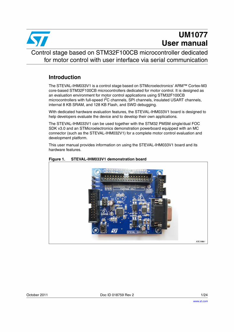
IntroductionThe STEVAL-IHM033V1 is a control stage based on STMicroelectronics’ ARM™ Cortex-M3 core-based STM32F100CB microcontrollers dedicated for motor control. It is designed as an evaluation environment for motor control applications using STM32F100CB microcontrollers with full-speed I2C channels, SPI channels, insulated USART channels, internal 8 KB SRAM, and 128 KB Flash, and SWD debugging.
With dedicated hardware evaluation features, the STEVAL-IHM033V1 board is designed to help developers evaluate the device and to develop their own applications.
The STEVAL-IHM033V1 can be used together with the STM32 PMSM single/dual FOC SDK v3.0 and an STMicroelectronics demonstration powerboard equipped with an MC connector (such as the STEVAL-IHM032V1) for a complete motor control evaluation and development platform.
This user manual provides information on using the STEVAL-IHM033V1 board and its hardware features.
Figure 1. STEVAL-IHM033V1 demonstration board
www.st.com
Contents UM1077
2/24 Doc ID 018759 Rev 2
Contents
1 Main features . . . . . . . . . . . . . . . . . . . . . . . . . . . . . . . . . . . . . . . . . . . . . . . 5
2 Hardware layout and configuration . . . . . . . . . . . . . . . . . . . . . . . . . . . . . 6
2.1 Power supply . . . . . . . . . . . . . . . . . . . . . . . . . . . . . . . . . . . . . . . . . . . . . . . 7
2.2 Boot option . . . . . . . . . . . . . . . . . . . . . . . . . . . . . . . . . . . . . . . . . . . . . . . . . 7
2.3 Clock source . . . . . . . . . . . . . . . . . . . . . . . . . . . . . . . . . . . . . . . . . . . . . . . . 7
2.4 Reset source . . . . . . . . . . . . . . . . . . . . . . . . . . . . . . . . . . . . . . . . . . . . . . . 7
2.5 Insulated RS232 . . . . . . . . . . . . . . . . . . . . . . . . . . . . . . . . . . . . . . . . . . . . . 7
2.6 16-pin SPI/I2C/SCI interface . . . . . . . . . . . . . . . . . . . . . . . . . . . . . . . . . . . . 7
2.7 Motor control . . . . . . . . . . . . . . . . . . . . . . . . . . . . . . . . . . . . . . . . . . . . . . . 8
2.8 Development and debug support . . . . . . . . . . . . . . . . . . . . . . . . . . . . . . . . 8
3 Connectors . . . . . . . . . . . . . . . . . . . . . . . . . . . . . . . . . . . . . . . . . . . . . . . . 9
3.1 Motor control connector J1 (J4) . . . . . . . . . . . . . . . . . . . . . . . . . . . . . . . . . 9
3.2 Insulated RS232 connector P1 . . . . . . . . . . . . . . . . . . . . . . . . . . . . . . . . . 10
3.3 16-pin SPI, I2C, SCI interface J3 parameters . . . . . . . . . . . . . . . . . . . . . . 11
3.4 Serial wire debugging connector J2 . . . . . . . . . . . . . . . . . . . . . . . . . . . . . 11
4 Schematics . . . . . . . . . . . . . . . . . . . . . . . . . . . . . . . . . . . . . . . . . . . . . . . 13
5 STEVAL-IHM033V1 IO assignments . . . . . . . . . . . . . . . . . . . . . . . . . . . 16
6 Using the STEVAL-IHM033V1 with the STM32 FOC firmware library . 18
6.1 Environmental considerations . . . . . . . . . . . . . . . . . . . . . . . . . . . . . . . . . 18
6.2 Hardware requirements . . . . . . . . . . . . . . . . . . . . . . . . . . . . . . . . . . . . . . 19
6.3 Software requirements . . . . . . . . . . . . . . . . . . . . . . . . . . . . . . . . . . . . . . . 19
6.4 STM32 FOC firmware library v3.0 customizing . . . . . . . . . . . . . . . . . . . . 19
7 Bill of material . . . . . . . . . . . . . . . . . . . . . . . . . . . . . . . . . . . . . . . . . . . . . 21
8 References . . . . . . . . . . . . . . . . . . . . . . . . . . . . . . . . . . . . . . . . . . . . . . . . 22
9 Revision history . . . . . . . . . . . . . . . . . . . . . . . . . . . . . . . . . . . . . . . . . . . 23
UM1077 List of tables
Doc ID 018759 Rev 2 3/24
List of tables
Table 1. Motor control jumpers JP1, JP2 . . . . . . . . . . . . . . . . . . . . . . . . . . . . . . . . . . . . . . . . . . . . . . 8Table 2. Motor control connector J1 (J4) pin assignments . . . . . . . . . . . . . . . . . . . . . . . . . . . . . . . . . 9Table 3. Insulated RS232 connector P1 pin assignments . . . . . . . . . . . . . . . . . . . . . . . . . . . . . . . . 10Table 4. 16-pin SPI, I2C, SCI interface J3 pin assignments . . . . . . . . . . . . . . . . . . . . . . . . . . . . . . . 11Table 5. Serial wire debugging connector J2 pin assignments. . . . . . . . . . . . . . . . . . . . . . . . . . . . . 12Table 6. STEVAL-IHM033V1 IO assignments . . . . . . . . . . . . . . . . . . . . . . . . . . . . . . . . . . . . . . . . . 16Table 7. STEVAL-IHM033V1 motor control workbench parameters . . . . . . . . . . . . . . . . . . . . . . . . 19Table 8. Bill of material . . . . . . . . . . . . . . . . . . . . . . . . . . . . . . . . . . . . . . . . . . . . . . . . . . . . . . . . . . . 21Table 9. Document revision history . . . . . . . . . . . . . . . . . . . . . . . . . . . . . . . . . . . . . . . . . . . . . . . . . 23
List of figures UM1077
4/24 Doc ID 018759 Rev 2
List of figures
Figure 1. STEVAL-IHM033V1 demonstration board . . . . . . . . . . . . . . . . . . . . . . . . . . . . . . . . . . . . . . 1Figure 2. STEVAL-IHM033V1 block diagram . . . . . . . . . . . . . . . . . . . . . . . . . . . . . . . . . . . . . . . . . . . 6Figure 3. STEVAL-IHM033V1 board layout . . . . . . . . . . . . . . . . . . . . . . . . . . . . . . . . . . . . . . . . . . . . . 6Figure 4. Motor control connector J1/J4 (top view) . . . . . . . . . . . . . . . . . . . . . . . . . . . . . . . . . . . . . . . 9Figure 5. Insulated RS232 connector P1 (front view) . . . . . . . . . . . . . . . . . . . . . . . . . . . . . . . . . . . . 10Figure 6. 16-pin SPI, I2C, SCI interface J3 . . . . . . . . . . . . . . . . . . . . . . . . . . . . . . . . . . . . . . . . . . . . 11Figure 7. Serial wire debugging connector J2 . . . . . . . . . . . . . . . . . . . . . . . . . . . . . . . . . . . . . . . . . . 11Figure 8. Motor control connector . . . . . . . . . . . . . . . . . . . . . . . . . . . . . . . . . . . . . . . . . . . . . . . . . . . 13Figure 9. MCU connections . . . . . . . . . . . . . . . . . . . . . . . . . . . . . . . . . . . . . . . . . . . . . . . . . . . . . . . . 14Figure 10. Serial communication . . . . . . . . . . . . . . . . . . . . . . . . . . . . . . . . . . . . . . . . . . . . . . . . . . . . . 15
UM1077 Main features
Doc ID 018759 Rev 2 5/24
1 Main features
The STEVAL-IHM033V1 control stage has the following characteristics:
● Compact size
● STMicroelectronics ARM™ Cortex-M3 core-based STM32F100CB microcontroller
● Connector for interfacing with any STMicroelectronics demonstration powerboard equipped with an MC connector (such as the STEVAL-IHM032V1) with alternate functions (current reference, current limitation/regulation, method selection, current boost)
● The board is compatible with sinusoidal and trapezoidal control
● Insulated USART communication interface
● Non insulated UUSCI interface (see STEVAL-PCC009V4)
● External oscillator
● Reset button
● SWD for programming/debugging
● DAC outputs test points
Hardware layout and configuration UM1077
6/24 Doc ID 018759 Rev 2
2 Hardware layout and configuration
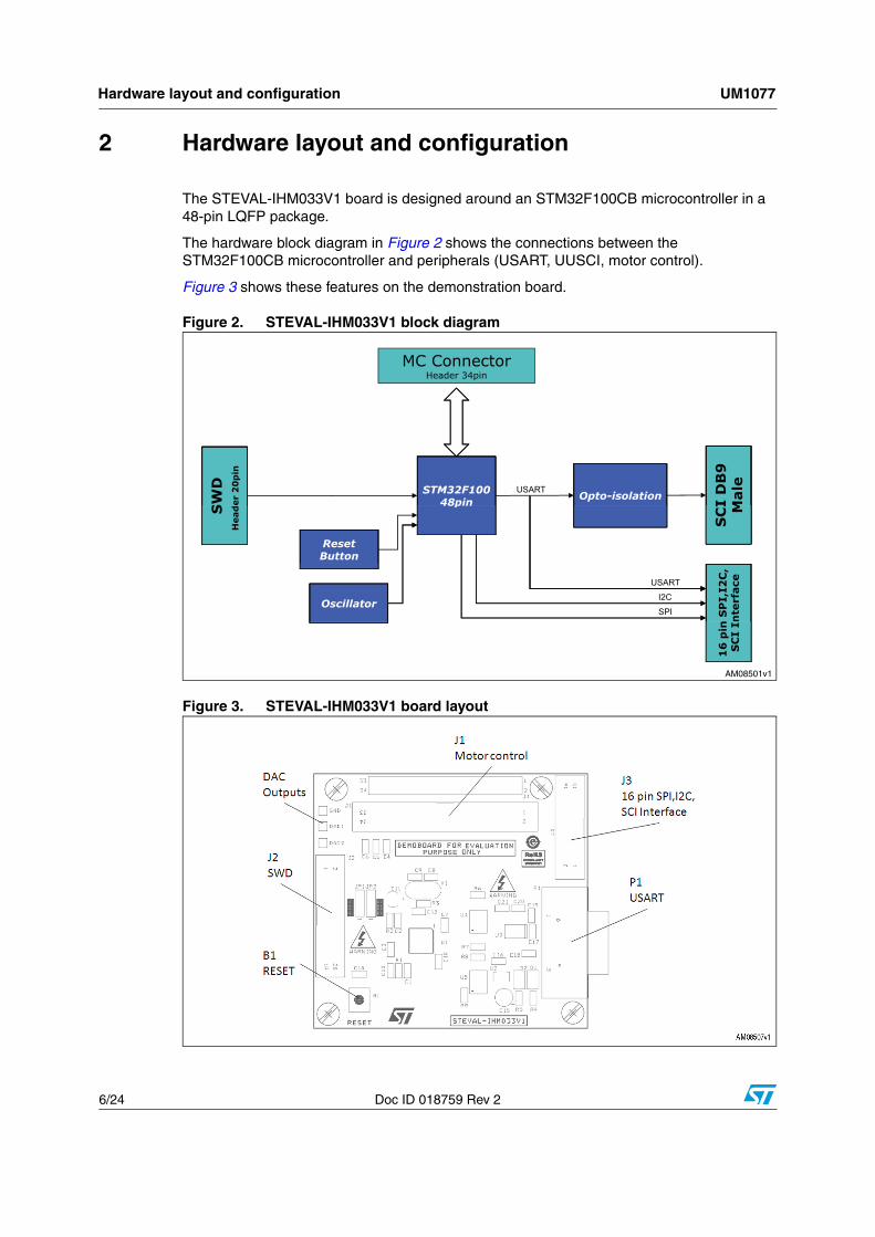
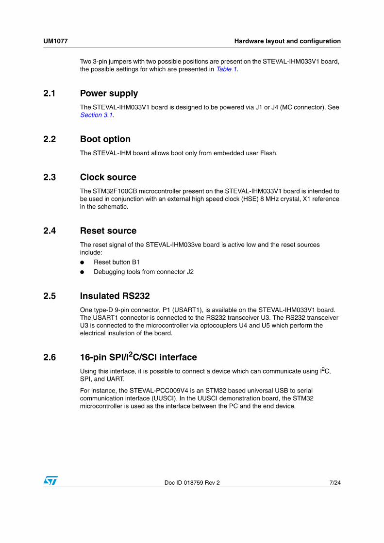
The STEVAL-IHM033V1 board is designed around an STM32F100CB microcontroller in a 48-pin LQFP package.
The hardware block diagram in Figure 2 shows the connections between the STM32F100CB microcontroller and peripherals (USART, UUSCI, motor control).
Figure 3 shows these features on the demonstration board.
Figure 2. STEVAL-IHM033V1 block diagram
Figure 3. STEVAL-IHM033V1 board layout
UM1077 Hardware layout and configuration
Doc ID 018759 Rev 2 7/24
Two 3-pin jumpers with two possible positions are present on the STEVAL-IHM033V1 board, the possible settings for which are presented in Table 1.
2.1 Power supplyThe STEVAL-IHM033V1 board is designed to be powered via J1 or J4 (MC connector). See Section 3.1.
2.2 Boot optionThe STEVAL-IHM board allows boot only from embedded user Flash.
2.3 Clock sourceThe STM32F100CB microcontroller present on the STEVAL-IHM033V1 board is intended to be used in conjunction with an external high speed clock (HSE) 8 MHz crystal, X1 reference in the schematic.
2.4 Reset sourceThe reset signal of the STEVAL-IHM033ve board is active low and the reset sources include:
● Reset button B1
● Debugging tools from connector J2
2.5 Insulated RS232One type-D 9-pin connector, P1 (USART1), is available on the STEVAL-IHM033V1 board. The USART1 connector is connected to the RS232 transceiver U3. The RS232 transceiver U3 is connected to the microcontroller via optocouplers U4 and U5 which perform the electrical insulation of the board.
2.6 16-pin SPI/I2C/SCI interfaceUsing this interface, it is possible to connect a device which can communicate using I2C, SPI, and UART.
For instance, the STEVAL-PCC009V4 is an STM32 based universal USB to serial communication interface (UUSCI). In the UUSCI demonstration board, the STM32 microcontroller is used as the interface between the PC and the end device.
Hardware layout and configuration UM1077
8/24 Doc ID 018759 Rev 2
2.7 Motor controlThe STEVAL-IHM033V1 board supports motor control via a 34-pin connector, J1 or J4, which provides all required control and feedback signals to and from a motor power-drive board. Available signals on this connector include emergency stop, speed or position feedbacks, 3-phase motor current, bus voltage sensor, heatsink temperature sensor coming from the motor drive board, and 6 channels of PWM control signals going to the motor drive circuit.
It is possible to use the J1 connector 34-way boxed header placed in the top side, or alternatively, the J4 connector 32-way double row female stripline placed in the bottom side to connect the STEVAL-IHM033V1 with one of STMicroelectronics’ demonstration powerboards equipped with an MC connector (such as STEVAL-IHM032v1). For the latter option it is possible to directly plug in the J4 connector to the MC connector of the powerboard respecting the polarity.
Special motor control operation is enabled by setting jumpers JP1, JP2 (see Table 1).
2.8 Development and debug supportThe following debug connector is available on the STEVAL-IHM033V1 board:
● J2, an industry standard 20-pin SWD interface connector for connection of debugging/programming tools for ARM core-based devices.
Table 1. Motor control jumpers JP1, JP2
Jumper Position Description
JP1
Between pin 1 and 2(Default setting)
Connect pin 27 of the J1 (J4) MC connector to the STM32F100CBT6B microcontroller pin PB11 (TIM2_CH4) used as PFC Synch
Between pin 2 and 3Connect pin 27 of the J1 (J4) MC connector to the STM32F100CBT6B microcontroller pin PA12 (TIM1_ETR) used as BLDC ETR
JP2
Between pin 1 and 2(Default setting)
Connect pin 29 of the J1 (J4) MC connector to the STM32F100CBT6B microcontroller pin PB10 (TIM2_CH3) used as PFC PWM
Between pin 2 and 3Connect pin 29 of the J1 (J4) MC connector to the STM32F100CBT6B microcontroller pin PA4 (DAC1_OUT) used as Curr. Ref.
UM1077 Connectors
Doc ID 018759 Rev 2 9/24
3 Connectors
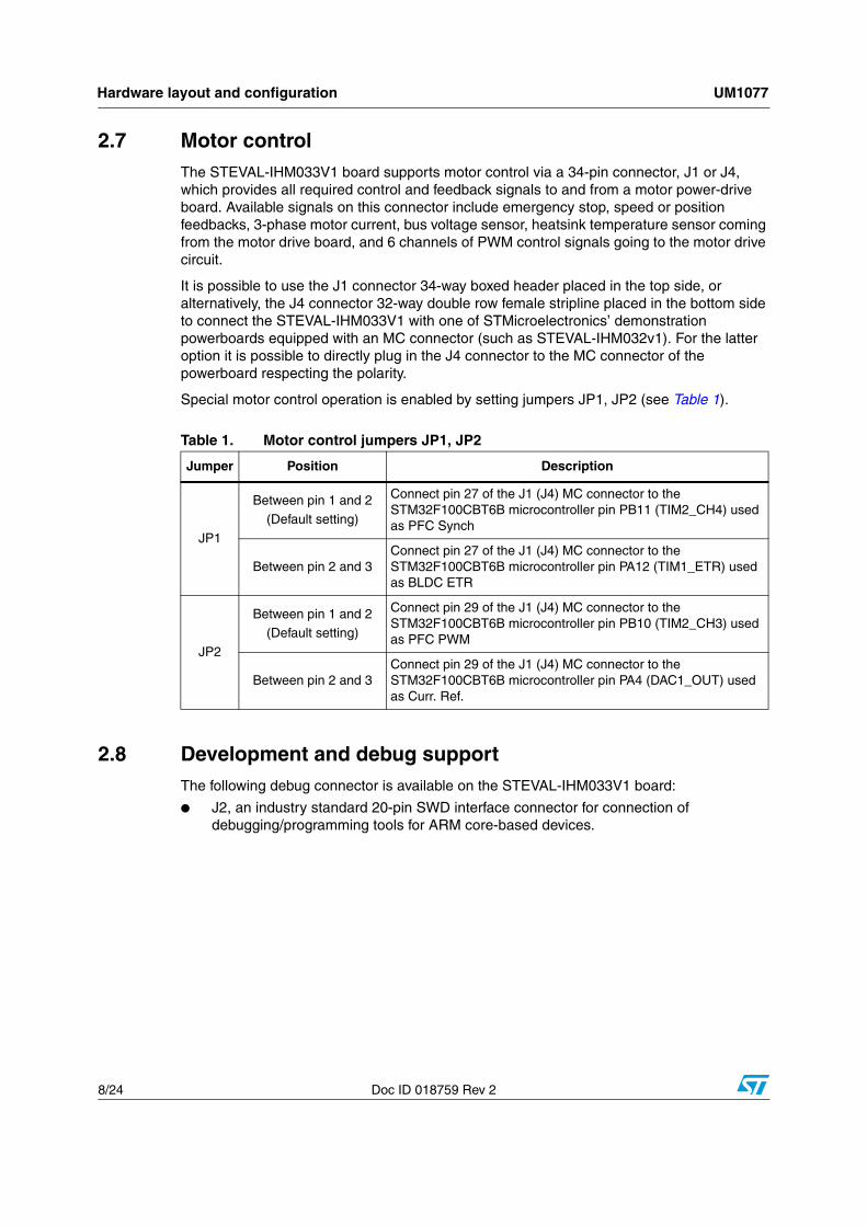
3.1 Motor control connector J1 (J4)
Figure 4. Motor control connector J1/J4 (top view)
Table 2. Motor control connector J1 (J4) pin assignments
J1/J4 pin Function Pin of
STM32F100CBJ1/J4 pin
Function Pin of
STM32F100CB
1 Emergency stop PB12 2 GND
3 PWM-UH PA8 4 GND
5 PWM-UL PB13 6 GND
7 PWM-VH PA9 8 GND
9 PWM-VL PB14 10 GND
11 PWM-WH PA10 12 GND
13 PWM-WL PB15 14 Bus voltage PA3
15 Phase A current,
BEMF sampling method selection
PA6 16 GND
17 Phase B current PA7 18 GND
19 Phase C current PB0 20 GND
21 NTC bypass PB2 22 GND
23 Dissipative brake,
OCP Boost PB9 24 GND
25 Not connected 26 Heatsink
temperature PB1
27 PFC synch,
6Step - current regulation feedback
PB11 orPA12 (see Table 1)
28 VDD µ (required
3.3 V)
Connectors UM1077
10/24 Doc ID 018759 Rev 2
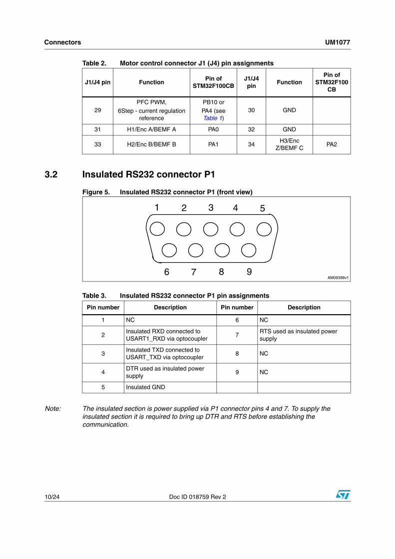
3.2 Insulated RS232 connector P1
Figure 5. Insulated RS232 connector P1 (front view)
Note: The insulated section is power supplied via P1 connector pins 4 and 7. To supply the insulated section it is required to bring up DTR and RTS before establishing the communication.
29 PFC PWM,
6Step - current regulation reference
PB10 or
PA4 (see Table 1)
30 GND
31 H1/Enc A/BEMF A PA0 32 GND
33 H2/Enc B/BEMF B PA1 34 H3/Enc
Z/BEMF C PA2
Table 2. Motor control connector J1 (J4) pin assignments
J1/J4 pin Function Pin of
STM32F100CBJ1/J4 pin
Function Pin of
STM32F100CB
Table 3. Insulated RS232 connector P1 pin assignments
Pin number Description Pin number Description
1 NC 6 NC
2Insulated RXD connected to USART1_RXD via optocoupler
7RTS used as insulated power supply
3Insulated TXD connected to USART_TXD via optocoupler
8 NC
4DTR used as insulated power supply
9 NC
5 Insulated GND
UM1077 Connectors
Doc ID 018759 Rev 2 11/24
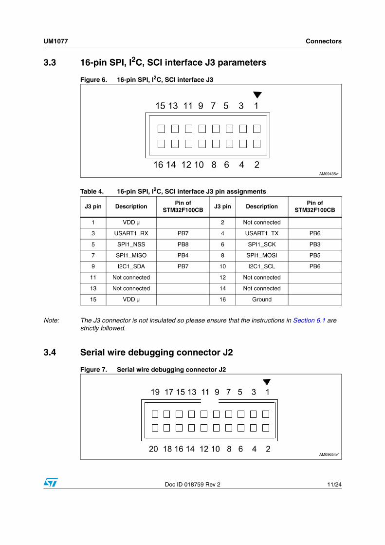
3.3 16-pin SPI, I2C, SCI interface J3 parameters
Figure 6. 16-pin SPI, I2C, SCI interface J3
Note: The J3 connector is not insulated so please ensure that the instructions in Section 6.1 are strictly followed.
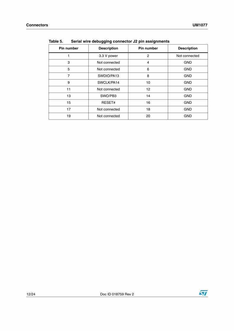
3.4 Serial wire debugging connector J2
Figure 7. Serial wire debugging connector J2
Table 4. 16-pin SPI, I2C, SCI interface J3 pin assignments
J3 pin DescriptionPin of
STM32F100CBJ3 pin Description
Pin of STM32F100CB
1 VDD µ 2 Not connected
3 USART1_RX PB7 4 USART1_TX PB6
5 SPI1_NSS PB8 6 SPI1_SCK PB3
7 SPI1_MISO PB4 8 SPI1_MOSI PB5
9 I2C1_SDA PB7 10 I2C1_SCL PB6
11 Not connected 12 Not connected
13 Not connected 14 Not connected
15 VDD µ 16 Ground
Connectors UM1077
12/24 Doc ID 018759 Rev 2
Table 5. Serial wire debugging connector J2 pin assignments
Pin number Description Pin number Description
1 3.3 V power 2 Not connected
3 Not connected 4 GND
5 Not connected 6 GND
7 SWDIO/PA13 8 GND
9 SWCLK/PA14 10 GND
11 Not connected 12 GND
13 SWO/PB3 14 GND
15 RESET# 16 GND
17 Not connected 18 GND
19 Not connected 20 GND
UM1077 Schematics
Doc ID 018759 Rev 2 13/24
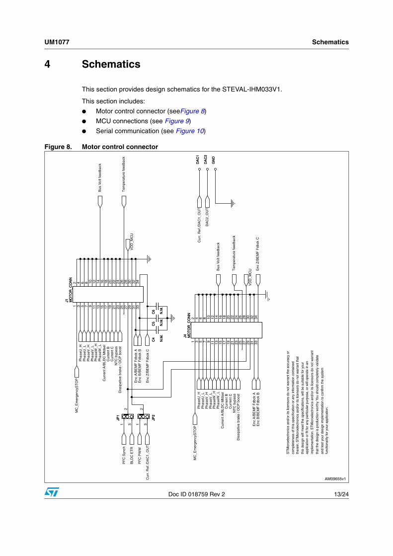
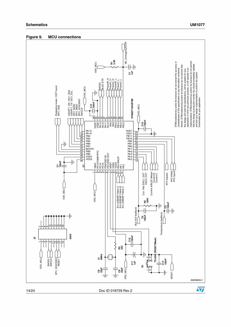
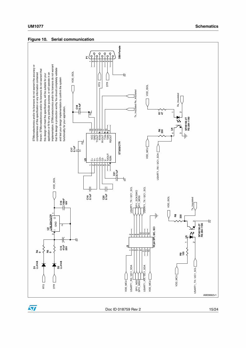
4 Schematics
This section provides design schematics for the STEVAL-IHM033V1.
This section includes:
● Motor control connector (seeFigure 8)
● MCU connections (see Figure 9)
● Serial communication (see Figure 10)
Figure 8. Motor control connector
Schematics UM1077
14/24 Doc ID 018759 Rev 2
Figure 9. MCU connections
UM1077 Schematics
Doc ID 018759 Rev 2 15/24
Figure 10. Serial communication
STEVAL-IHM033V1 IO assignments UM1077
16/24 Doc ID 018759 Rev 2
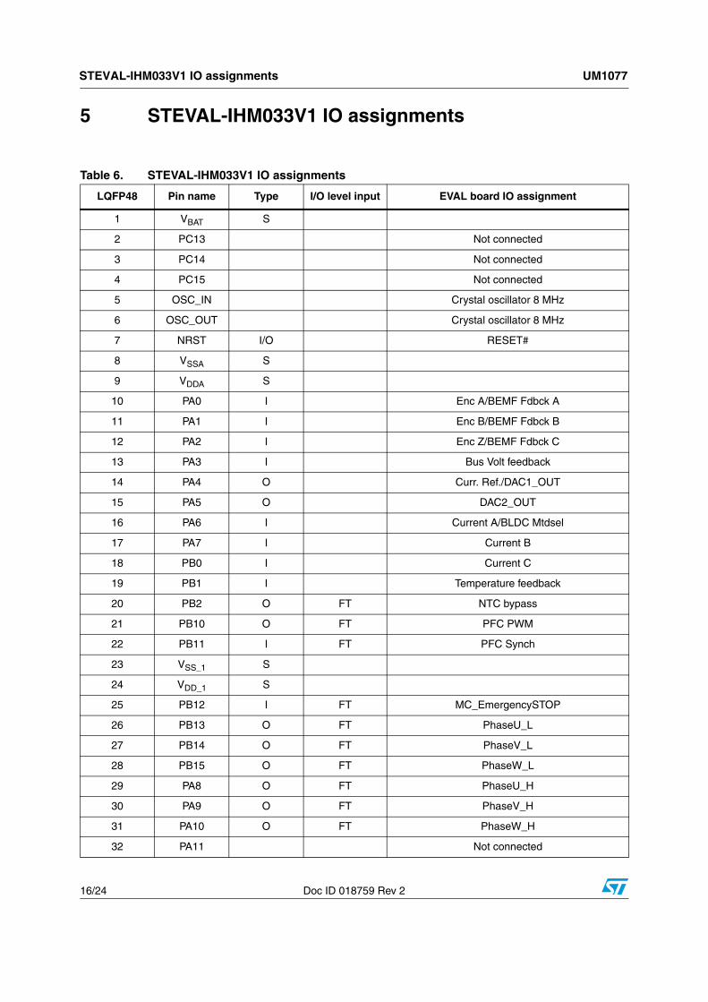
5 STEVAL-IHM033V1 IO assignments
Table 6. STEVAL-IHM033V1 IO assignments
LQFP48 Pin name Type I/O level input EVAL board IO assignment
1 VBAT S
2 PC13 Not connected
3 PC14 Not connected
4 PC15 Not connected
5 OSC_IN Crystal oscillator 8 MHz
6 OSC_OUT Crystal oscillator 8 MHz
7 NRST I/O RESET#
8 VSSA S
9 VDDA S
10 PA0 I Enc A/BEMF Fdbck A
11 PA1 I Enc B/BEMF Fdbck B
12 PA2 I Enc Z/BEMF Fdbck C
13 PA3 I Bus Volt feedback
14 PA4 O Curr. Ref./DAC1_OUT
15 PA5 O DAC2_OUT
16 PA6 I Current A/BLDC Mtdsel
17 PA7 I Current B
18 PB0 I Current C
19 PB1 I Temperature feedback
20 PB2 O FT NTC bypass
21 PB10 O FT PFC PWM
22 PB11 I FT PFC Synch
23 VSS_1 S
24 VDD_1 S
25 PB12 I FT MC_EmergencySTOP
26 PB13 O FT PhaseU_L
27 PB14 O FT PhaseV_L
28 PB15 O FT PhaseW_L
29 PA8 O FT PhaseU_H
30 PA9 O FT PhaseV_H
31 PA10 O FT PhaseW_H
32 PA11 Not connected
UM1077 STEVAL-IHM033V1 IO assignments
Doc ID 018759 Rev 2 17/24
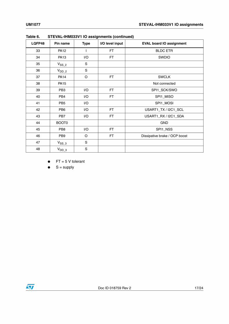
● FT = 5 V tolerant
● S = supply
33 PA12 I FT BLDC ETR
34 PA13 I/O FT SWDIO
35 VSS_2 S
36 VDD_2 S
37 PA14 O FT SWCLK
38 PA15 Not connected
39 PB3 I/O FT SPI1_SCK/SWO
40 PB4 I/O FT SPI1_MISO
41 PB5 I/O SPI1_MOSI
42 PB6 I/O FT USART1_TX / I2C1_SCL
43 PB7 I/O FT USART1_RX / I2C1_SDA
44 BOOT0 GND
45 PB8 I/O FT SPI1_NSS
46 PB9 O FT Dissipative brake / OCP boost
47 VSS_3 S
48 VDD_3 S
Table 6. STEVAL-IHM033V1 IO assignments (continued)
LQFP48 Pin name Type I/O level input EVAL board IO assignment

Using the STEVAL-IHM033V1 with the STM32 FOC firmware library UM1077
18/24 Doc ID 018759 Rev 2
6 Using the STEVAL-IHM033V1 with the STM32 FOC firmware library
The “STM32 FOC firmware library v3.0” provided along with the STM3210B-MCKIT performs the field-oriented control (FOC) of a permanent magnet synchronous motor (PMSM) in both sensor and sensorless configurations.
It is possible to configure the firmware to use the STEVAL-IHM033V1 as the control stage of the motor control system.
This section describes the customizing to be applied to the “STM32 FOC firmware library V3.0” in order for the firmware to be compatible with the STEVAL-IHM033V1.
6.1 Environmental considerations
Warning: The STEVAL-IHM033V1 demonstration board is not electrically insulated; if it is connected to a high voltage powerboard, it must only be used in a power laboratory; the voltage used in the drive system presents a shock hazard.
The kit is not electrically isolated from the powerboard. This topology is very common in motor drives. The microprocessor is grounded by the integrated ground of the DC bus. The microprocessor and associated circuitry are hot and MUST be isolated from user controls and communication interfaces.
Warning: Any measurement equipment must be isolated from the main power supply before powering up the motor drive. To use an oscilloscope with the kit, it is safer to isolate the DC supply AND the oscilloscope. This prevents a shock from occurring as a result of touching any single point in the circuit, but does NOT prevent shocks when touching two or more points in the circuit.
An isolated AC power supply can be constructed using an isolation transformer and a variable transformer.
Note: Isolating the application rather than the oscilloscope is highly recommended in any case.
UM1077 Using the STEVAL-IHM033V1 with the STM32 FOC firmware library
Doc ID 018759 Rev 2 19/24
6.2 Hardware requirementsThe following items are required to run the STEVAL-IHM033V1 together with the “STM32 FOC firmware library”.
● The STEVAL-IHM033V1 board or MB459B board (powerboard present in the STM32 MC kit) or any other demonstration board with MC connector.
● A high-voltage insulated AC power supply up to 230 Vac
● A programmer/debugger dongle for the control board (not included in the package). To program/debug the STEVAL-IHM033V1, a dongle with single wire debugging capabilities (SWD) is required. Use of an insulated dongle is always recommended.
● A 3-phase brushless motor with permanent magnet rotor (not included in the package)
● An insulated oscilloscope (as necessary)
● An insulated multimeter (as necessary)
6.3 Software requirementsTo customize, compile, and download the “STM32 FOC firmware library v3.0”, a toolchain must be installed. Please refer to the UM1052 user manual for complete details on how to set up the proper toolchain and refer to the control board user manual for further details.
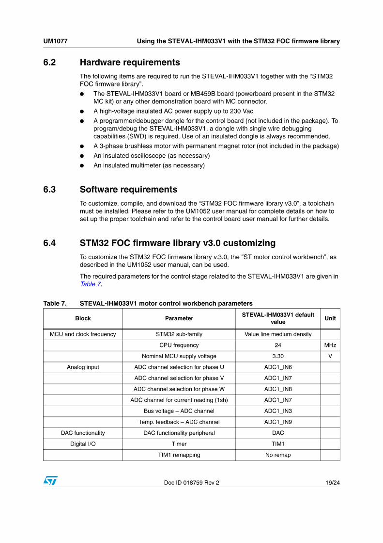
6.4 STM32 FOC firmware library v3.0 customizingTo customize the STM32 FOC firmware library v.3.0, the “ST motor control workbench”, as described in the UM1052 user manual, can be used.
The required parameters for the control stage related to the STEVAL-IHM033V1 are given in Table 7.
Table 7. STEVAL-IHM033V1 motor control workbench parameters
Block ParameterSTEVAL-IHM033V1 default
valueUnit
MCU and clock frequency STM32 sub-family Value line medium density
CPU frequency 24 MHz
Nominal MCU supply voltage 3.30 V
Analog input ADC channel selection for phase U ADC1_IN6
ADC channel selection for phase V ADC1_IN7
ADC channel selection for phase W ADC1_IN8
ADC channel for current reading (1sh) ADC1_IN7
Bus voltage – ADC channel ADC1_IN3
Temp. feedback – ADC channel ADC1_IN9
DAC functionality DAC functionality peripheral DAC
Digital I/O Timer TIM1
TIM1 remapping No remap
Using the STEVAL-IHM033V1 with the STM32 FOC firmware library UM1077
20/24 Doc ID 018759 Rev 2
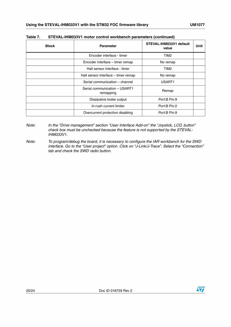
Note: In the “Drive management” section “User Interface Add-on” the “Joystick, LCD, button” check box must be unchecked because the feature is not supported by the STEVAL-IHM033V1.
Note: To program/debug the board, it is necessary to configure the IAR workbench for the SWD interface. Go to the “User project” option. Click on “J-Link/J-Trace”. Select the “Connection” tab and check the SWD radio button.
Encoder interface - timer TIM2
Encoder interface – timer remap No remap
Hall sensor interface - timer TIM2
Hall sensor interface – timer remap No remap
Serial communication – channel USART1
Serial communication – USART1 remapping
Remap
Dissipative brake output Port:B Pin:9
In-rush current limiter Port:B Pin:2
Overcurrent protection disabling Port:B Pin:9
Table 7. STEVAL-IHM033V1 motor control workbench parameters (continued)
Block ParameterSTEVAL-IHM033V1 default
valueUnit
UM1077 Bill of material
Doc ID 018759 Rev 2 21/24
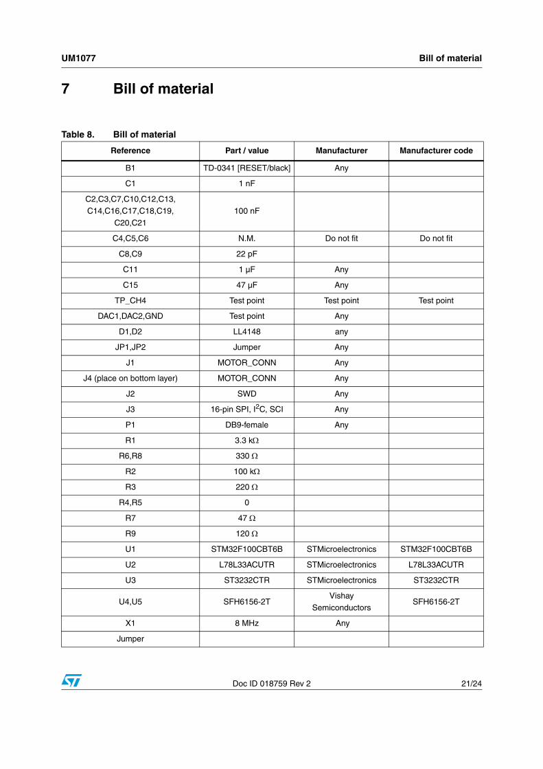
7 Bill of material
Table 8. Bill of material
Reference Part / value Manufacturer Manufacturer code
B1 TD-0341 [RESET/black] Any
C1 1 nF
C2,C3,C7,C10,C12,C13,C14,C16,C17,C18,C19,
C20,C21
100 nF
C4,C5,C6 N.M. Do not fit Do not fit
C8,C9 22 pF
C11 1 µF Any
C15 47 µF Any
TP_CH4 Test point Test point Test point
DAC1,DAC2,GND Test point Any
D1,D2 LL4148 any
JP1,JP2 Jumper Any
J1 MOTOR_CONN Any
J4 (place on bottom layer) MOTOR_CONN Any
J2 SWD Any
J3 16-pin SPI, I2C, SCI Any
P1 DB9-female Any
R1 3.3 kΩ
R6,R8 330 Ω
R2 100 kΩ
R3 220 Ω
R4,R5 0
R7 47 Ω
R9 120 Ω
U1 STM32F100CBT6B STMicroelectronics STM32F100CBT6B
U2 L78L33ACUTR STMicroelectronics L78L33ACUTR
U3 ST3232CTR STMicroelectronics ST3232CTR
U4,U5 SFH6156-2TVishay
SemiconductorsSFH6156-2T
X1 8 MHz Any
Jumper
References UM1077
22/24 Doc ID 018759 Rev 2
8 References
This user manual provides information on the hardware features and use of the STEVALIHM033V1 demonstration board. For additional information on supporting software and tools, refer to the following:
● STM32F100xx datasheet
● RM0041 reference manual
● UM1052 user manual
● UM1053 user manual
● TN0516 technical note
● http://www.st.com/mcu/ web site, which is dedicated to the complete STMicroelectronics microcontroller portfolio.
Please contact the nearest ST sales office or support team to obtain the required documentation if it is not included in the software package received or available on the ST web site (www.st.com).
UM1077 Revision history
Doc ID 018759 Rev 2 23/24
9 Revision history
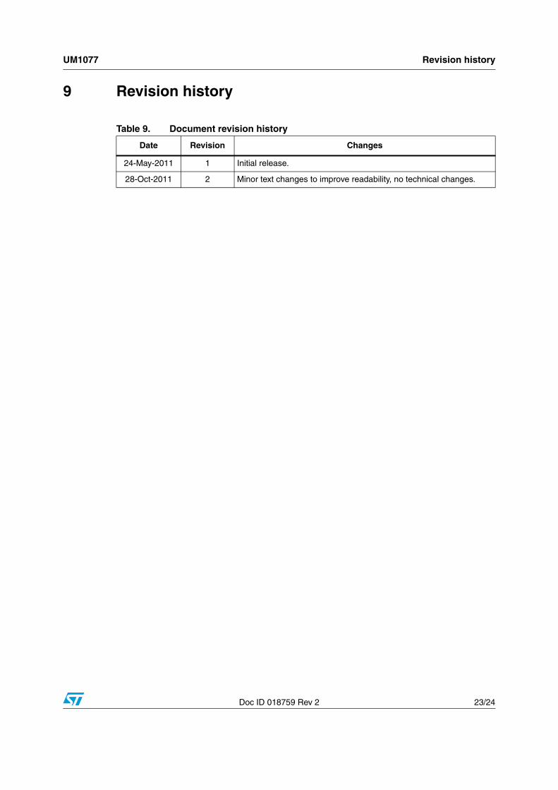
Table 9. Document revision history
Date Revision Changes
24-May-2011 1 Initial release.
28-Oct-2011 2 Minor text changes to improve readability, no technical changes.
UM1077
24/24 Doc ID 018759 Rev 2
Please Read Carefully:
Information in this document is provided solely in connection with ST products. STMicroelectronics NV and its subsidiaries (“ST”) reserve theright to make changes, corrections, modifications or improvements, to this document, and the products and services described herein at anytime, without notice.
All ST products are sold pursuant to ST’s terms and conditions of sale.
Purchasers are solely responsible for the choice, selection and use of the ST products and services described herein, and ST assumes noliability whatsoever relating to the choice, selection or use of the ST products and services described herein.
No license, express or implied, by estoppel or otherwise, to any intellectual property rights is granted under this document. If any part of thisdocument refers to any third party products or services it shall not be deemed a license grant by ST for the use of such third party productsor services, or any intellectual property contained therein or considered as a warranty covering the use in any manner whatsoever of suchthird party products or services or any intellectual property contained therein.
UNLESS OTHERWISE SET FORTH IN ST’S TERMS AND CONDITIONS OF SALE ST DISCLAIMS ANY EXPRESS OR IMPLIEDWARRANTY WITH RESPECT TO THE USE AND/OR SALE OF ST PRODUCTS INCLUDING WITHOUT LIMITATION IMPLIEDWARRANTIES OF MERCHANTABILITY, FITNESS FOR A PARTICULAR PURPOSE (AND THEIR EQUIVALENTS UNDER THE LAWSOF ANY JURISDICTION), OR INFRINGEMENT OF ANY PATENT, COPYRIGHT OR OTHER INTELLECTUAL PROPERTY RIGHT.
UNLESS EXPRESSLY APPROVED IN WRITING BY TWO AUTHORIZED ST REPRESENTATIVES, ST PRODUCTS ARE NOTRECOMMENDED, AUTHORIZED OR WARRANTED FOR USE IN MILITARY, AIR CRAFT, SPACE, LIFE SAVING, OR LIFE SUSTAININGAPPLICATIONS, NOR IN PRODUCTS OR SYSTEMS WHERE FAILURE OR MALFUNCTION MAY RESULT IN PERSONAL INJURY,DEATH, OR SEVERE PROPERTY OR ENVIRONMENTAL DAMAGE. ST PRODUCTS WHICH ARE NOT SPECIFIED AS "AUTOMOTIVEGRADE" MAY ONLY BE USED IN AUTOMOTIVE APPLICATIONS AT USER’S OWN RISK.
Resale of ST products with provisions different from the statements and/or technical features set forth in this document shall immediately voidany warranty granted by ST for the ST product or service described herein and shall not create or extend in any manner whatsoever, anyliability of ST.
ST and the ST logo are trademarks or registered trademarks of ST in various countries.
Information in this document supersedes and replaces all information previously supplied.
The ST logo is a registered trademark of STMicroelectronics. All other names are the property of their respective owners.
© 2011 STMicroelectronics - All rights reserved
STMicroelectronics group of companies
Australia - Belgium - Brazil - Canada - China - Czech Republic - Finland - France - Germany - Hong Kong - India - Israel - Italy - Japan - Malaysia - Malta - Morocco - Philippines - Singapore - Spain - Sweden - Switzerland - United Kingdom - United States of America
www.st.com