Embed Size (px)
Citation preview
Copyright (c) 2013 IEEE. Personal use is permitted. For any other purposes, permission must be obtained from the IEEE by emailing [email protected].
This article has been accepted for publication in a future issue of this journal, but has not been fully edited. Content may change prior to final publication.
1
Control Strategy for Current Harmonic ProgrammedAC Active Electronic Power Loads
Joselito A. Heerdt, Member, IEEE, Daniel F. Coutinho Senior Member, IEEE, Samir A. Mussa Member, IEEE,and Marcelo L. Heldwein Member, IEEE
Abstract—Alternating-current (AC) active electronic loads(AEL) based on PWM converters, capable of emulating nonlinearloads, require effective current control techniques and powerstages. These two aspects of an AEL are interdependent mainlydue to the presence of EMC filters to reduce electromagneticemissions. However, the filter components affect the dynamicsof the system. In this context, this work proposes a digitallyimplemented control strategy comprising state feedback, robustobserver, phase-locked loop and a linear current controller tocope with AC AEL applications. The control oriented modelingand the control system design are presented. Experimentalresults obtained from a 10 kW three-phase three-level pulsewidth modulation (PWM) converter prototype illustrate anddemonstrate the feasibility of the proposed AEL control strategy.
Index Terms—AC active load, Three-level converters, Currentcontrol techniques, State feedback, State observers.
NOMENCLATURE
ia EUT currentiA filter inductor currentva mains or EUT voltagevA converter switched voltagevC,a voltage at the filter terminalsvC,A voltage across the damping capacitorE dc-link voltageLa EUT output inductanceLA converter filter inductanceLaA Inductance in case La = 0Ca filter capacitorCA damping network capacitorRA damping network resistorSj switch jsj switching function of switch Sj
Dj diode jp, n, 0 dc-link terminalsj∗ reference value of jjpk peak value of jfo EUT fundamental frequencyh harmonic order (integer)t time
Manuscript received March 6, 2013. Accepted for publication July 31, 2013.Copyright 2013 IEEE. Personal use of this material is permitted. However,
permission to use this material for any other purposes must be obtained fromthe IEEE by sending a request to [email protected] .
J. A. Heerdt is with the Electrical Power Processing ResearchGroup (nPEE), Electrical Engineering Department (DEE), Santa CatarinaState University (UDESC), Joinville, SC, 89223-100, Brazil (e-mail: [email protected]).
D. F. Coutinho is with the Dept. Automation and Systems (DAS), FederalUniversity of Santa Catarina (UFSC), Florianopolis, SC, 88040-970, Brazil(e-mail: [email protected]).
S. A. Mussa and M. L. Heldwein are with the Electronics and Electri-cal Engineering Department (EEL), Federal University of Santa Catarina(UFSC), Florianopolis, SC, 88040-970, Brazil (e-mail: [email protected];[email protected]).
Tsw switching periodfsw switching frequencyfs sampling frequencyfo EUT voltage fundamental frequency~x system state vector~y system output vector~u system input vector~w disturbance vectorA system state matrixB system input matrixC system output matrixD system feedforward matrixI identity matrix~K state feedback vectork1, k2, k3 state feedback gainsp1, p2, p3 desired poles location~js,Js Simplified system vectors and matrices~jo,Jo Luenberger observer vectors and matricesj estimated value of jM Luenberger observer gain matrixC(s) current controllerkc current controller gainksf state feedback common gaind duty-cyclek sampling number
I. INTRODUCTION
BURN-IN ROUTINES, equipment operation test duringresearch and development phases, maintenance proce-
dures, are among the test procedures that take advantagefrom active electronic loads (AEL). Regarding AC AELs, theequipment that potentially profit from testing with AC AELare: distribution transformers, power system protection equip-ment, transmission lines, AC regulators, generators, energymeasurement devices, uninterruptible power supplies (UPS)and others. Such testing procedures promote energy savings[1]. An example is presented in [2], where an economicanalysis shows that an electronic load that regenerates energyto the grid can have its payback time in less than five months.
Nonlinear loads connected to distribution networks generateharmonic currents that do not add to their active power dueto the frequency mismatch with the grid voltage. However,their circulation through feeders produces Joule losses andelectromagnetic (EM) emissions. This creates harmful effects.In this context, each equipment that is subject to distortedcurrents is required to withstand the additional requirementsproduced by such currents. Therefore, test setups includingthe injection of high amplitude harmonic currents into energysupply equipment are able to provide close to real applicationconditions. These setups could use dedicated nonlinear in
Copyright (c) 2013 IEEE. Personal use is permitted. For any other purposes, permission must be obtained from the IEEE by emailing [email protected].
This article has been accepted for publication in a future issue of this journal, but has not been fully edited. Content may change prior to final publication.
2
addition to linear loads or use AC AELs with programmableharmonic currents to emulate field applications.
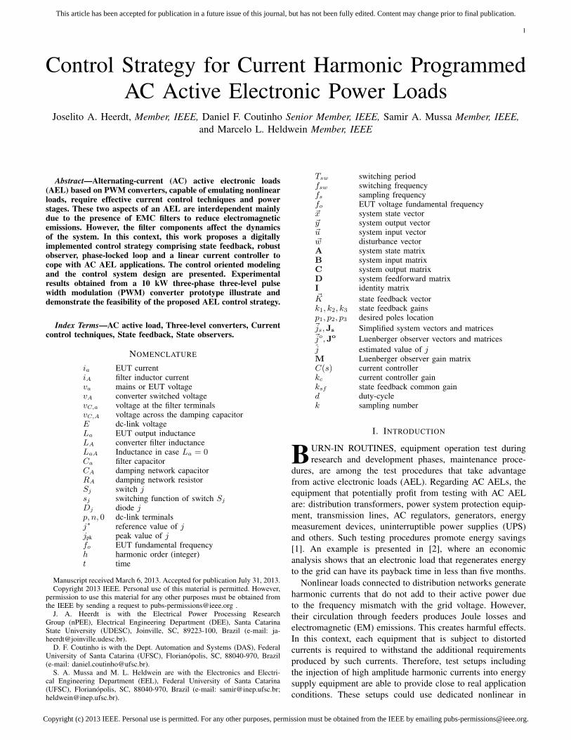
AC AELs as illustrated in Fig. 1 can be implementedthrough different technologies and with various objectives (seeAppendix A). The basic blocks of an AC AEL are a powersource, an electronic converter that drains power from the EUTand a regenerative inverter that feeds power back to the powersource to increase test efficiency.
There are several works related to the emulation of ACloads trough electronic power converters. For instance, anAEL based on a three-phase diode rectifier fed by a three-phase AC-side transformer was proposed in [3] to generatedistorted test currents. However, no explicit control was usedand the load characteristics could not be programmed. Anapproach based on a linear amplifier was proposed in [4],which presents high control bandwidth, but poor efficiency.This poses limitations for the testing of high power equipment.A hybrid amplifier approach, i.e., the connection of a linearamplifier with a switched circuit is proposed for AELs in [5] toincrease the current control bandwidth with higher efficiency.A PI-type current controller was considered in [6] to generatecurrent distortion in a three-phase switched inverter-based ACAEL. This approach leads to even higher efficiency. On theother hand, switch mode AELs generate high frequency (HF)emissions and are more complex from the control perspective.
The active AC load based on switch mode power convertersoption leads to several benefits and must be considered. Po-tential benefits are [2]: low energy consumption and reductionof peak power demand due to mains energy re-injection,installation costs reduction due to lower cooling requirementswhen compared with linear amplifier based AELs, and smallertest equipment footprint because of resistive loads are not em-ployed. In addition, an active AC load is easily scalable, highlyflexible regarding changing current test profiles and providedynamic testing capability, i.e., the reference currents can beprogrammed. A Dynamic Electronic Load Simulator (DELS)for AC power supplies was briefly described in [7] withoutdetailing the used current controller. Reference [8] proposesthe use of a resonant plus P-type current controller to reducereference tracking errors. However, the latter reference doesnot include an LCL filter configuration, which dramaticallyincreases the current control challenge. A repetitive controlleris employed in [9] for a similar power circuit as in [8] alsofor an L type of filter. A single inductor (L filter) is againused in [10] to couple an equipment under test (EUT) anda PWM inverter-based electronic AC load. This configurationinjects relevant HF current contents in the EUT or requiresvery large inductors, which are both non desirable. Thus,EMC filters should be employed in order to prevent highfrequency current components from circulating in the testeddevice. Typical filters would lead to LC or LCL configurations[11]–[15].
An LCL filter is a reasonable approach regarding overallfilter volume, weight and cost, but it adds resonances to thecircuit that should be handled by the inverter control system.Furthermore, the tested device output impedance changes thecontrol plant as well. Thus, a robust control system shouldbe designed. Reference [16] proposes an AC active electronic
EUT
Power flow
+
_AC
sourc
e
Regenerativeinverter
AC AELconverter
EM
I filt
er
EM
I filt
er
Programmableload (current control)
DC-link andcurrent control
Fig. 1. Simplified single-phase equivalent block diagram of an AC activeelectronic load comprised of an AEL converter and a regenerative inverterthat feeds power back to the AC source.
load that is employed to test power distribution transformers.The topology uses an input LCL filter followed by a standardthree-phase inverter. It is shown that the resonant behavior ofpractical LCL filters with low damping is quite challenging forcontrolling the inverter. The solution given in [16] proposes adamping resistor in series with the filter capacitor. However,this reduces the capacitor filtering effect regarding HF currentcomponents leading to the oversizing of the filter componentsand/or poor EMC filtering performance. Reference [17] pro-poses an LCL single-phase PWM inverter-based DELS thatis employed for operational and burn-in tests for AC and DCpower supplies emulating linear RLC-type loads. The currentcontroller employs a full order system state feedback and a2 kHz control bandwidth was obtained with 50 kHz switchingfrequency.
This work proposes a control strategy suitable for a switchmode AC AEL. The AC AEL is based on a modern PowerElectronics three-level converter and the proposed controlstrategy is shown to be able to cope with the added challengesof an LCL filter with high grid interfacing inductance values.The final objective is to reproduce a given current harmonicprofile. The application focus is placed on the testing ofdistribution transformers that are subject to heavy harmonicpollution. Namely, the testing of K-rated transformers and har-monic mitigating transformers, among others. The proposedcontrol design approach for this system employs the state-space description, which is the basis for a state feedbackstrategy aiming to mitigate the influence of the LCL filter onthe controlled plant. The eigenvalues of the system are chosento provide active damping and a control law for the closed-loop system leads to a control bandwidth of approximately11 kHz with 66 kHz switching frequency. The equipmentunder test (EUT) current, i.e. the grid interface transformercurrent, is not directly measured. Therefore, the LCL filter canbe segregated and shielded from all electronic components inthe converter layout. However, the current to be controlled isideally the current on the EUT side, i.e., through the inductorlocated at the grid side. Another option would be to senseboth currents as in [17], but this adds cost and tends toworsen the filter performance regarding the electromagneticemissions. In the proposed control system, a Luenbergerobserver (cf. section IV-B) provides information regarding theEUT current that is indirectly estimated and controlled. Theobserver gains are chosen based on a robust H∞ formulationthat minimizes the influence to external disturbances errors. Acomprehensive control design example illustrates the proposed

Copyright (c) 2013 IEEE. Personal use is permitted. For any other purposes, permission must be obtained from the IEEE by emailing [email protected].
This article has been accepted for publication in a future issue of this journal, but has not been fully edited. Content may change prior to final publication.
3
42.4539.75 40.05 42.750
100
200
300
400
Voltage
[V
] i IGBT
010
20
30
40
Time [ms]
Curr
ent [A
]
v IGBT
A 0
+
+
LA
SpDp
Dn
p
nSn
S02
D02 D01
S01iA
E2
E2
a
39.9537.20 37.60 40.35
0
100
200
300
400
Voltage
[V
]
i
010
20
30
40
Time [ms]
Curr
ent [A
]
v SiC,JFET
err
eon
eoff
10 15 20 25 300
Isw [A]
Sw
itch
ing
ener
gy [µJ]
400
200
800
600
Si IGBT+SiC Diode
SiC JFET+SiC Diode
(a) (b) (c) (d)
SiC,JFET
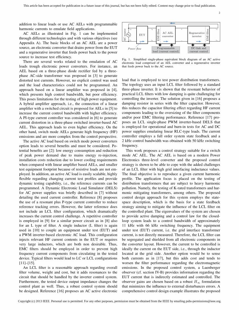
Fig. 2. (a) One of the phases (phase A) of a four-wires three-level bidirectional TCC converter; (b) switching test voltage and current at the 1.2 kV SiCJFET vSiC,JFET; (c) switching test voltage and current at the 600 V Si IGBT vIGBT; and (d) measured switching losses.
design procedure.Even though the current control of LCL based converter
has been widely analyzed in the literature [11], [12], [14],[18]–[23], the challenge with an AC AEL is fundamentallydifferent, since high performance EUT currents control mustbe achieved. In addition, this requires the knowledge of theEUT-side filter currents, which is not the case in most of theproposed LCL control schemes.
The work is structured as follows. The AC AEL three-level power converter prototype is described in section IIand its control oriented model is detailed in section III. Theproposed control strategy is explained in section IV. Finally,experimental results are given in section V and section VIends the paper. A classification for AEL systems is presentedin Appendix A. Finally, a guideline for the dc-link voltagechoice of an AC AEL is proposed in Appendix B.
II. AC AEL POWER CONVERTER DESCRIPTION
The switching cells of traditional bi-directional three-levelvoltage source converters, such as the Neutral Point Clamped(NPC) [24], [25] and the Flying Capacitor (FC) [26]–[28] aretypically employed as three-level inverters. These topologiesare commonly rated for very high power (hundreds of kWup to MW) and the use of such structures as bi-directionalconverters in the lower kW range is not widespread in in-dustrial applications. However, AC AELs present a potentialapplication for such converters since the size of the ac-sidefilter can be reduced for a given switching frequency (fsw)due to the lower values of the voltage steps at the converter ac-side terminals. Fig. 2(a) shows a three-level transistor clampedconverter (TCC) topology that presents the same externalcharacteristics of the NPC. However, two of the switchesper phase are subject to the full DC-link voltage [29], [30].This topology presents the potential for reducing the totallosses when compared to the NPC for low voltage (< 1 kV)applications [31], [32]. Thus, it is employed as the basis for themodeled three-phase AC AEL. As other three-level topologies,the converter at hand might lead to unbalances at the partialdc-link voltages. In the proposed implementation the balanceshould be provided by a downstream converter connected tothe mains in order to regenerate energy during EUT testing.A four-wires connection to an EUT is considered in thefollowing. Thus, all circuit and control diagrams considernon-coupled single-phase variables. The four-wire connectionis based on the model of an EUT that is a hypotheticaldistribution transformer with Y windings. This is a typical case
for three-phase transformers feeding single-phase non linearloads, where the triplen harmonics add up in the neutral cable.
The built three-phase converter lab prototype is shown inFig. 3. Switches S01–D01 and S02–D02 employ 600 V SiIGBTs (IRF IRG4PC50W) and Si Stealth diodes (FairchildISL9R3060G2). The full dc-link voltage is chosen at800 V. Thus, 1.2 kV normally-off SiC JFETs (SemiSouthSJEP120R063) and SiC diodes (SemiSouth SDP30S120) areused for Sp–Dp and Sn–Dn. Relatively low switching losses[31] are obtained as shown in Fig. 2(b)–(d). The main circuitspecifications are: rated power (for purely sinusoidal balancedcurrents) Prated = 10 kW; line-to-line RMS voltage Vl−l =380 V; dc-link voltages E/2 = 400 V (see Appendix B). Thecomputed semiconductor losses for the converter operating atrated conditions as a unit power factor rectifier are: switchinglosses Psw ∼= 60 W; conduction losses Pcond ∼= 87 W.
The converter modulation is an in-phase disposition (IPD)scheme. The appropriate steps between the transitions of theswitching signals, i.e., a logic sequence that prevents short-circuit at any instant is employed as presented in [31].
Filtering is required between the EUT and the converterto limit electromagnetic emissions from the active electronicload. The use of step-up power converters requires that in-
DC-link cap
Gate driversAdapted gate driversCM inductor
DSC
Heatsink Heatsink HeatsinkDC-link cap
Filter inductors Filter inductor
DC-link caps
DC-link cap
PCB
(a)
(b)
A
+
+LA
p
n
0
EEMC filter
EU
T t
erm
inal
s
SiC1.2 kV
Si600 V2
E2
a
CaCA
RA
Bb
LCM
C
N
c
Fig. 3. Built three-phase TCC converter lab prototype. Dimensions: (∼= 300×185× 105) mm.
Copyright (c) 2013 IEEE. Personal use is permitted. For any other purposes, permission must be obtained from the IEEE by emailing [email protected].
This article has been accepted for publication in a future issue of this journal, but has not been fully edited. Content may change prior to final publication.
4
ductors are used to implement a current source characteristicat the AC-side of the converter. However, if only an L-type filter was used, the volume and weight of such filterwould be very large. In addition, large inductance values limitthe achievable control bandwidth. Thus, a second order LCfilter leads to much reduced passive components dimensionsand weight. It leads to reduced inductance that potentiallyincreases converter dynamics. On the other hand, the addedcapacitance leads to a resonance that can be minimized withpassive or active (lossless) damping. In addition, commonmode emissions filtering must also be included in the filter.Thus, the filter configuration in Fig. 3(a) is used. This canbe seen as an LC filter since the common mode inductorLCM leakage inductance is typically small. However, thiswork considers an LCL filter configuration (see Fig. 4) dueto the presence of a non negligible output inductance for theEUT. The EMC filter design is not within the scope of thiswork since it requires information on the complete test setup.References on the design of EMC filters for high switchingfrequency three-level converters are given in [33]–[35]. Thefilter parameters are LA = 420 µH, Ca = 1 µF, RA = 33 Ωand CA = 1 µF. The EUT output inductance is assumed fordesigning reasons to be unknown, but bounded to a giveninterval
La ∈ [ Lmina , Lmax
a ] , Lmina = 380 µH , Lmax
a = 570 µH ,(1)
with La = 456 µH being its nominal level. This leads to astrong resonance close to 10 kHz.
III. CONTROL ORIENTED MODEL
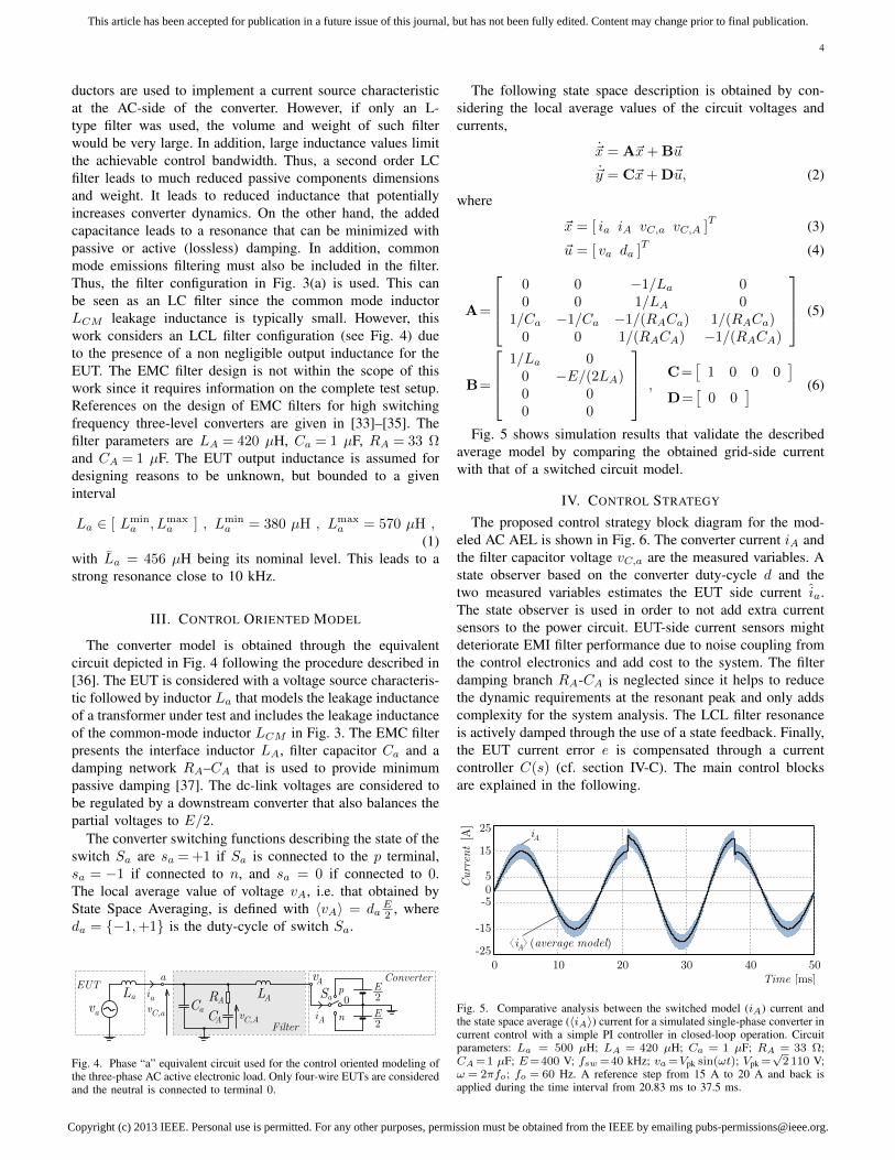
The converter model is obtained through the equivalentcircuit depicted in Fig. 4 following the procedure described in[36]. The EUT is considered with a voltage source characteris-tic followed by inductor La that models the leakage inductanceof a transformer under test and includes the leakage inductanceof the common-mode inductor LCM in Fig. 3. The EMC filterpresents the interface inductor LA, filter capacitor Ca and adamping network RA–CA that is used to provide minimumpassive damping [37]. The dc-link voltages are considered tobe regulated by a downstream converter that also balances thepartial voltages to E/2.
The converter switching functions describing the state of theswitch Sa are sa = +1 if Sa is connected to the p terminal,sa = −1 if connected to n, and sa = 0 if connected to 0.The local average value of voltage vA, i.e. that obtained byState Space Averaging, is defined with 〈vA〉 = da
E2 , where
da = −1,+1 is the duty-cycle of switch Sa.
Sa
ConverterAv
LALa
a
C
Filter
aCA
RAva
EUT p
n
0
E2
E2
iA
iavC,a vC,A
Fig. 4. Phase “a” equivalent circuit used for the control oriented modeling ofthe three-phase AC active electronic load. Only four-wire EUTs are consideredand the neutral is connected to terminal 0.
The following state space description is obtained by con-sidering the local average values of the circuit voltages andcurrents,
~x = A~x+ B~u
~y = C~x+ D~u, (2)
where
~x = [ ia iA vC,a vC,A ]T (3)
~u = [ va da ]T (4)
A=
0 0 −1/La 00 0 1/LA 0
1/Ca −1/Ca −1/(RACa) 1/(RACa)0 0 1/(RACA) −1/(RACA)
(5)
B=
1/La 0
0 −E/(2LA)0 00 0
,C=
[1 0 0 0
]D=
[0 0
] (6)
Fig. 5 shows simulation results that validate the describedaverage model by comparing the obtained grid-side currentwith that of a switched circuit model.
IV. CONTROL STRATEGY
The proposed control strategy block diagram for the mod-eled AC AEL is shown in Fig. 6. The converter current iA andthe filter capacitor voltage vC,a are the measured variables. Astate observer based on the converter duty-cycle d and thetwo measured variables estimates the EUT side current ia.The state observer is used in order to not add extra currentsensors to the power circuit. EUT-side current sensors mightdeteriorate EMI filter performance due to noise coupling fromthe control electronics and add cost to the system. The filterdamping branch RA-CA is neglected since it helps to reducethe dynamic requirements at the resonant peak and only addscomplexity for the system analysis. The LCL filter resonanceis actively damped through the use of a state feedback. Finally,the EUT current error e is compensated through a currentcontroller C(s) (cf. section IV-C). The main control blocksare explained in the following.
−25
−15
−505
15
25
Curr
ent[A]
iA
i (average model)A
0 10 20 30 40 50Time [ms]
Fig. 5. Comparative analysis between the switched model (iA) current andthe state space average (〈iA〉) current for a simulated single-phase converter incurrent control with a simple PI controller in closed-loop operation. Circuitparameters: La = 500 µH; LA = 420 µH; Ca = 1 µF; RA = 33 Ω;CA =1 µF; E=400 V; fsw =40 kHz; va =Vpk sin(ωt); Vpk =
√2 110 V;
ω = 2πfo; fo = 60 Hz. A reference step from 15 A to 20 A and back isapplied during the time interval from 20.83 ms to 37.5 ms.

Copyright (c) 2013 IEEE. Personal use is permitted. For any other purposes, permission must be obtained from the IEEE by emailing [email protected].
This article has been accepted for publication in a future issue of this journal, but has not been fully edited. Content may change prior to final publication.
5
A. Active Damping through State Feedback
State Feedback is a pole placement technique that reallo-cates the original poles of the controlled system in a way thatthe closed loop system presents a desired dynamic behavior.The states ia, vC,a and iA are here used. A linear combinationof these states generates signal d2 in Fig. 6. This techniquedoes not change the number of poles nor the position of theoriginal zeros of the system.
The model described in (2)–(6) is reduced by eliminatingthe damping components RA and CA. Thus, the simplifiedsystem used for the control design is
~xs = As~xs + Bs~u, (7)
where
~xs = [ ia iA vC,a ]T (8)
As =
0 0 −1/La0 0 1/LA
1/Ca −1/Ca 0
(9)
Bs =
[1/La 0
0 −E/(2LA)
]T. (10)
The state feedback implementation is seen in Fig. 7, where~K = [ k1 k2 k3 ]T . From Fig. 7(a) it follows that
~xs = [As −Bs~K]~xs + Bs~u. (11)
Hence, the closed loop characteristic equation is as follows:
det[sI− (As −Bs~K)] = 0. (12)
Assuming that the desired characteristic equation is definedby three real poles p1, p2 and p3, the following is obtained
s3− (p1+p2+p3)s2 +(p3(p1+p2)+p1p2)s−p1p2p3 =0 (13)
Solving the system including (12) and (13) gives
d’
vaAv
L
State
feedback
A
C(s)
iA
ka,m
ka,r
kd
kd
ia
ia
d1
d2
d
d
ia*
^
La
CavC,a
ic
State
observer
e
Fig. 6. Ac active electronic load current control block diagram.
xu~ u
(a) (b)
s
s K x
k2
k3i^a
k1iA
vC,a d 2x = A x + B us ss s
.
Fig. 7. Ac active electronic load state feedback block diagram.
k1 = −2LAE· (p1 + p2 + p3), (14)
k2 =2LACaE
[(p1 p2 + p2 p3 + p3 p1)− La + LA
CaLaLA
], (15)
k3 = −k1 − 2(p1 p2 p3)LaLACa
E. (16)
B. State Observer
The EUT side current ia is estimated by means of aLuenberger state observer [38]. The observer gain is designedbased on the robust H∞ formulation as proposed in [39],[40]. Precisely, the gain of the correction term (i.e., the errorbetween the measurements and their estimate) is designed inorder to minimize the effects of external disturbances as wellas the errors due to model inaccuracy on the estate estimation.
In light of the uncertainty on the value of La, we recastthe system dynamics in terms of a disturbance vector ~wcomprising exogenous signals and modeling errors:
~xs = As~xs + Bs1da + Bs2 ~w
~y = Cs~xs, (17)
where As is the matrix As evaluated at La = La, and
Bs1 =
0− E
2LA
0
, Bs2 =
1La
δLa0 00 0
, ~w=
[vavC,a
](18)
with δLa representing a bounded uncertainty which modelsthe error between 1/La and 1/La.
Then, the Luenberger observer is defined as follows:
~ξ = As~ξ + Bs1da + M(~y − ~yξ), (19)
~yξ = Cs~ξ, (20)
~η = Cη~ξ, (21)
~ξ = [ ξ1 ξ2 ξ3 ]T , (22)
where ~η is the signal to be estimated and M is a constantmatrix to be determined.
Let ~e := ~xs − ~ξ and ~ηe := Cη~xs − ~η be respectively theestimation error vector and the observation error. Thus, theestimation error dynamics can be cast by means of:
~e =(As −MCs
)~e+ Bs2 ~w , (23)
~ηe = Cη~e (24)
The observer gain matrix M is designed aiming to mitigatethe effects of external disturbances and modeling errors on theestimation ia of ia by minimizing the following cost function:
minM
sup‖ ~ηe ‖2‖ ~w ‖2
, (25)
for all La belonging to the interval [Lmina , Lmax
a ].The results proposed in [39], [40] are applied for the gain
determination. The optimization problem in these referencesis recast in terms of linear matrix inequality constraints [41],

Copyright (c) 2013 IEEE. Personal use is permitted. For any other purposes, permission must be obtained from the IEEE by emailing [email protected].
This article has been accepted for publication in a future issue of this journal, but has not been fully edited. Content may change prior to final publication.
6
Ed
e
s1
s1
s1
2LA
1LA
1
M
1La
11
i
M12
iA
iA^
e
M22
v
vC,ae
M21
iev
e
M31
i
M32
ev
ia^
ia^
aC
1
aC
vC,a^
d
iAvC,a
Inputs:
Output:
Fig. 8. Ac active electronic load Luenberger state observer block diagram.
which are numerically solved with appropriate software [42].This approach leads to
M =
M11 M12
M21 M22
M31 M32
= 106 ·
1.9525 −0.2007−0.3356 0.10281.9665 −0.2049
(26)
Then, the complete observer structure as illustrated in Fig. 8can be written as follows: diA
dtdvC,a
dtdiadt
= Ao ·
iAvC,aia
+ Bo ·
diAvC,a
, (27)
where
Ao =
−M11−1LA−M12 0
1Ca−M21 −M22
−1Ca
−M311La−M32 0
(28)
and
Bo =
E2LA
M11 M12
0 M21 M22
0 M31 M32
, (29)
and the estimation error vector is ~e = [ eiA evC,aeia ]T .
C. Current Controller
Two integrators are employed in order to provide improvedcurrent reference following capability for the circuit to performits AC AEL function. Two zeros, one at −200 rad/s and theother at −6 · 103 rad/s, are included in order to position thepoles of the system as presented in Fig. 9. The root locuspresented in Fig. 9 considers the state feedback and a currentcontroller C(s) defined as
C(s) = kcs2 + 6.2 · 103s+ 1.2 · 106
s2. (30)
Poles are at the origin, −20 ·103 rad/s and −12 ·103 rad/s.The placement considered an upper bound at one tenth of theswitching frequency to guarantee a reliable performance.
D. Digital Control Issues and Implementation
The previous analysis and design parameters were per-formed considering continuous implementations of all systemblocks. However, it is well known that the digital imple-mentation of the control and modulation blocks might bringfurther challenges to the control performance and stability.The main influences of digital implementations are relatedto analog-to-digital (AD) conversion, computation time andsampling frequency. The main effects are typically modeledthrough transport delays. An example is the simulated dynamicresponse seen in Fig. 5, which is obtained with the proposedcontrol strategy without considering the digital implementationissues and a switching frequency of fsw = 40 kHz. Suchdynamic response is not possible when the AD delay and adouble update mode modulation scheme are used. Increasingthe sampling frequency allows to improve this situation. For
4Real axis [s 10 ]−1
4Im
agi
nary
axis
[s
10 ]
−1
−2.5 −2 −1.5 −1 −0.5 0−3
−2
−1
0
1
2
3
Fig. 9. Root locus of the controlled system including the plant, the currentcontroller and the state feedback. Circuit parameters: La = 500 µH; LA =420 µH; Ca = 1 µF; RA = 33 Ω; CA = 1 µF and E = 400 V.
−60
−40
−20
0
20
Magn
itude
[dB
]
360
270
180
90
0
Phase
[deg
]
102
103
104
Frequency [Hz]
L = 700 µHa
L = 300 µHa
L = 500 µHa
Fig. 10. Closed loop Bode diagram of the controlled system resultingfrom computer simulations including the power circuit and the main digitalcontrol blocks, i.e. delays, quantization, sample-and-hold, PWM with doubleupdate mode and the complete control structure. Circuit parameters: La =300; 500; 700 µH; LA = 420 µH; Ca = 1 µF; RA = 33 Ω; CA = 1 µFand E = 400 V. It is important to notice that according to section B thepeak current reference for higher harmonic frequencies is decreased. For thecase at hand the current peak reference was linearly decreased from 15 A at60 Hz down to 1 A at 30 kHz.

Copyright (c) 2013 IEEE. Personal use is permitted. For any other purposes, permission must be obtained from the IEEE by emailing [email protected].
This article has been accepted for publication in a future issue of this journal, but has not been fully edited. Content may change prior to final publication.
7
−20−10
01020
Curr
ent[A
]
0 10 20 30 40 50Time [ms]
(a) (b) (c)
(d) (e) (f)
−20−10
01020
Curr
ent[A
]
−20−10
01020
Curr
ent[A
]
0 10 20 30 40 50Time [ms]
−20−10
01020
Curr
ent[A
]
−20−10
01020
Curr
ent[A
]
0 10 20 30 40 50Time [ms]
−20−10
01020
Curr
ent[A
]
Curr
ent[A
]
0 10 20 30 40 50Time [ms]
Curr
ent[A
]
−15
0
15
Curr
ent[A
]
0 10 20 30 40 50Time [ms]
−15
0
15
−15
0
15
−15
0
15
Curr
ent[A
]−10−505
10
Curr
ent[A
]
0 10 20 30 40 50Time [ms]
−10−505
10
Curr
ent[A
]
iA*
iA
iA
iA
iA*
iA
iA
iA
iA*
iA
iA
iA
iA*
iA
iA
iA
iA*
iA
iA
iA
iA*
iA
iA
iA
L = 3000 µHa
L = 3000 µHaL = 500 µHa
L = 500 µHa
L = 1 µHa
L = 1 µHa
Fig. 11. Simulation results for triangular current references with 60 Hz and 660 Hz, i.e. (a), (b) and (c) with fo = 60 Hz and (d), (e) and (f) with fo = 660 Hzfor three different EUT inductances: (a) and (d) La = 1 µH; (b) and (e) La = 500 µH; and, (c) and (f) La = 3000 µH. Simulations of the controlledsystem including the power circuit and the main digital control blocks, i.e. delays, quantization, sample-and-hold, PWM with double update mode and thecomplete digital control blocks. Circuit parameters: LA = 420 µH; Ca = 1 µF; RA = 33 Ω; CA = 1 µF and E = 400 V.
instance, a sampling frequency of 160 kHz allows to increasethe precision of the proposed observer and improve the dy-namic response to close to the continuous time one. However,a large sampling frequency increases the noise levels mainly atthe current measurement due to the approximation of samplinginstants to switching instants. Furthermore, the delay associ-ated to the updating of the duty-cycle is not reduced. Thus, thestraightforward way to obtain the expected dynamic behavioris to increase the switching frequency. Computer simulationstudies to evaluate the effects of the digital implementationwere carried out. The simulation model includes: quantizersand zero-order hold (ZOH) blocks to emulate the effect ofthe AD converter in the current and voltage sensors; an IPDmodulation scheme employing the double update PWM modeto guarantee noise free samples; limiters to model saturationeffects in the control loops; and, the discrete implementation ofall presented control blocks. An analysis of the AEL switchingfrequency on the performance of the current reproduction wasdone based on the simulation results and a switching frequencyof fsw=66 kHz was chosen leading to a sampling frequencyof fs=132 kHz.
The control laws are discretized based on the chosen switch-ing frequency with the help of Matlab and are described in thefollowing discretized models.
The current controller is defined with
d1(k) = kc [2917e(k)− 5700e(k − 1)+
+2783e(k − 2)] + 2d1(k−1)− d1(k−2) (31)
where kc = 1.5 · 10−5 is the current controller gain and krefers to the sampling number.
The employed state feedback discrete model expression is
d2(k) = ksf[54.705·10−3iA(k)+
−3.673·10−3vC,a(k)− 52.172·10−3ia(k)]
(32)
where ksf = 0.6 is the state feedback gain.Finally, the future states of the observer are
iA(k + 1) =Ao11iA(k) +Ao12vC,a(k) +Ao13ia(k)+
+Bo11d(k) +Bo12iA(k) +Bo13vC,a(k)
vC,a(k + 1) =Ao21iA(k) +Ao22vC,a(k) +Ao23ia(k)+
+Bo21d(k) +Bo22iA(k) +Bo23vC,a(k)
ia(k + 1) =Ao31iA(k) +Ao32vC,a(k) +Ao33ia(k)+
+Bo31d(k) +Bo32iA(k) +Bo33vC,a(k). (33)
The frequency response regarding the tracking of the currentreference is shown in Fig. 10 for three values of EUT induc-tance La = 500 µH ±40%. The presented closed loop Bodediagram considers computer simulations with the controlledsystem including the power circuit and the main digital controlblocks, i.e. analog-to-digital conversion (ADC) delays, quanti-zation, sample-and-hold, PWM with double update mode, statefeedback, observer and current controller. The closed loopsystem bandwidth measured at −3 dB approaches 11 kHz.However, it is important for the AC AEL that the phase delayis small for its harmonic reference following function. Thus,the practical frequency range is closer to 2 kHz depending onthe EUT inductance. Lower EUT inductances lead to a largerbandwidth.
The robustness and accuracy of the designed state observeris shown in Fig. 11. Six operation conditions are presented,namely: triangular current references with 60 Hz and 660 Hz,i.e. h = 1 and h = 11 for three different EUT inductancesLa = 1, 500, 3000 µH. The triangular reference signal presentsa rich harmonic spectrum and, thus, is used for this anal-ysis. The peak current reference is varied accordingly foraccounting for the saturation effects presented in section B.The control performance is acceptable for the cases whereh = 1 and also for h = 11 and La = 1, 500 µH. Thecontrol performance is poor with La = 3000 µH and h = 11.
Copyright (c) 2013 IEEE. Personal use is permitted. For any other purposes, permission must be obtained from the IEEE by emailing [email protected].
This article has been accepted for publication in a future issue of this journal, but has not been fully edited. Content may change prior to final publication.
8
However, the EUT current estimation is adequate even for thiscase.
The floating point digital signal controller DSCTMS320F28335 (150 MIPS) available from Texas Instrumentsis used to implement the control algorithm in the laboratoryprototype.
V. EXPERIMENTAL RESULTS
The final specifications of the test setup are given in Table I.A q-PLL type phase locked loop [44] was employed at the
converter terminals to derive the synchronization signal to thevoltage vC,a. This can also be made at the supply terminals.The PLL was designed with a 12 Hz bandwidth and 55phasemargin.
The dc-link terminals p, n, 0 were connected to two wellregulated dc sources. Furthermore, the dc-link capacitors weredesigned to provide voltage ripple lower than 4% under ratedsingle-phase power, i.e. one third of the rated three-phasepower. This is to minimize the influence of EUT unbalances inthe quality of the synthesized waveforms. Considering four-wire setups guarantee that the phases are decoupled. Thus,only single-phase results are presented in the following.
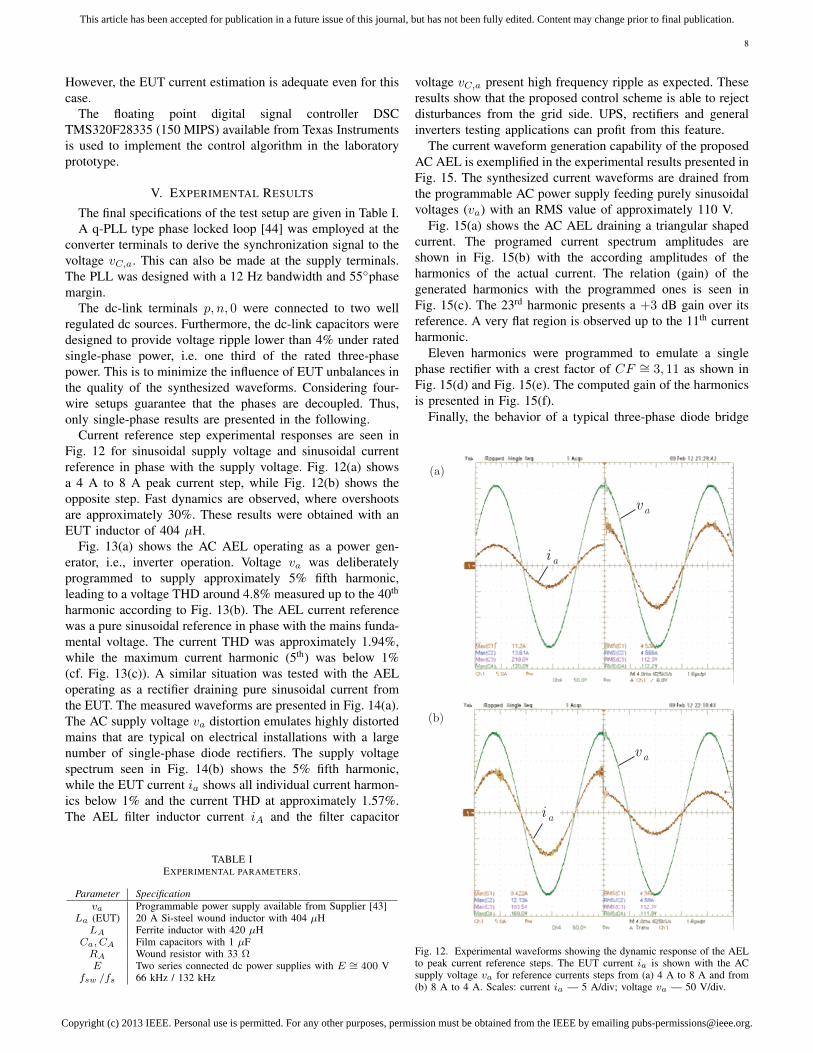
Current reference step experimental responses are seen inFig. 12 for sinusoidal supply voltage and sinusoidal currentreference in phase with the supply voltage. Fig. 12(a) showsa 4 A to 8 A peak current step, while Fig. 12(b) shows theopposite step. Fast dynamics are observed, where overshootsare approximately 30%. These results were obtained with anEUT inductor of 404 µH.
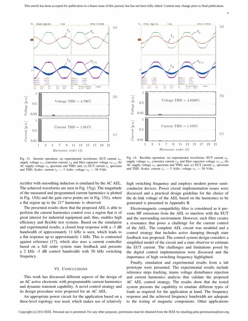
Fig. 13(a) shows the AC AEL operating as a power gen-erator, i.e., inverter operation. Voltage va was deliberatelyprogrammed to supply approximately 5% fifth harmonic,leading to a voltage THD around 4.8% measured up to the 40th
harmonic according to Fig. 13(b). The AEL current referencewas a pure sinusoidal reference in phase with the mains funda-mental voltage. The current THD was approximately 1.94%,while the maximum current harmonic (5th) was below 1%(cf. Fig. 13(c)). A similar situation was tested with the AELoperating as a rectifier draining pure sinusoidal current fromthe EUT. The measured waveforms are presented in Fig. 14(a).The AC supply voltage va distortion emulates highly distortedmains that are typical on electrical installations with a largenumber of single-phase diode rectifiers. The supply voltagespectrum seen in Fig. 14(b) shows the 5% fifth harmonic,while the EUT current ia shows all individual current harmon-ics below 1% and the current THD at approximately 1.57%.The AEL filter inductor current iA and the filter capacitor
TABLE IEXPERIMENTAL PARAMETERS.
Parameter Specificationva Programmable power supply available from Supplier [43]
La (EUT) 20 A Si-steel wound inductor with 404 µHLA Ferrite inductor with 420 µH
Ca, CA Film capacitors with 1 µFRA Wound resistor with 33 ΩE Two series connected dc power supplies with E ∼= 400 V
fsw /fs 66 kHz / 132 kHz
voltage vC,a present high frequency ripple as expected. Theseresults show that the proposed control scheme is able to rejectdisturbances from the grid side. UPS, rectifiers and generalinverters testing applications can profit from this feature.
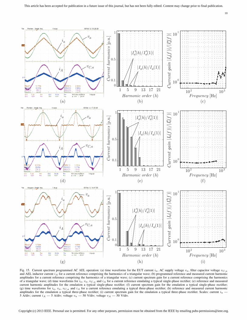
The current waveform generation capability of the proposedAC AEL is exemplified in the experimental results presented inFig. 15. The synthesized current waveforms are drained fromthe programmable AC power supply feeding purely sinusoidalvoltages (va) with an RMS value of approximately 110 V.
Fig. 15(a) shows the AC AEL draining a triangular shapedcurrent. The programed current spectrum amplitudes areshown in Fig. 15(b) with the according amplitudes of theharmonics of the actual current. The relation (gain) of thegenerated harmonics with the programmed ones is seen inFig. 15(c). The 23rd harmonic presents a +3 dB gain over itsreference. A very flat region is observed up to the 11th currentharmonic.
Eleven harmonics were programmed to emulate a singlephase rectifier with a crest factor of CF ∼= 3, 11 as shown inFig. 15(d) and Fig. 15(e). The computed gain of the harmonicsis presented in Fig. 15(f).
Finally, the behavior of a typical three-phase diode bridge
(a)
(b)
i a
v a
i a
v a
Fig. 12. Experimental waveforms showing the dynamic response of the AELto peak current reference steps. The EUT current ia is shown with the ACsupply voltage va for reference currents steps from (a) 4 A to 8 A and from(b) 8 A to 4 A. Scales: current ia — 5 A/div; voltage va — 50 V/div.
Copyright (c) 2013 IEEE. Personal use is permitted. For any other purposes, permission must be obtained from the IEEE by emailing [email protected].
This article has been accepted for publication in a future issue of this journal, but has not been fully edited. Content may change prior to final publication.
9
i a v a
i A v C,a
1 3 5 7 9 11 13 15 17 19 21
Harmonic order (h)
Curr
ent [p
.u.]
Current THD = 1.941%
0.01
0.5
1
(b)
Voltage
[p.u
.]
Voltage THD = 4.796%
(c)
0.05
0.5
1
(a)
Fig. 13. Inverter operation: (a) experimental waveforms: EUT current ia,supply voltage va, converter current iA and filter capacitor voltage vC,a; (b)AC supply voltage va spectrum and THD; and, (c) EUT current ia spectrumand THD. Scales: current ia — 5 A/div; voltage va — 50 V/div.
rectifier with smoothing inductors is emulated by the AC AEL.The achieved waveforms are seen in Fig. 15(g). The magnitudeof the measured and programmed current harmonics is plottedin Fig. 15(h) and the gain curve points are in Fig. 15(i), wherea flat region up to the 21st harmonic is observed.
The presented results show that the proposed AEL is able toperform the current harmonics control over a region that is ofgreat interest for industrial equipment and, thus, enables highefficiency and flexible test systems. Based on the simulationand experimental results, a closed loop response with a -3 dBbandwidth of approximately 11 kHz is seen, which leads toa flat response up to approximately 1 kHz. This is contrastedagainst reference [17], which also uses a current controllerbased on a full order system state feedback and presentsa 2 kHz -3 dB control bandwidth with 50 kHz switchingfrequency.
VI. CONCLUSIONS
This work has discussed different aspects of the design ofan AC active electronic with programmable current harmonicsand dynamic transient capability. A novel control strategy andits design procedure were proposed for an AC AEL.
An appropriate power circuit for the application based on athree-level topology was used, which makes use of relatively
1 3 5 7 9 11 13 15 17 19 21
Harmonic order (h)
Curr
ent [p
.u.]
Current THD = 1.570%
0.01
0.5
1
(b)
Voltage
[p.u
.]
Voltage THD = 4.8566%
(c)
0.05
0.5
1
(a)
i av a
i Av C,a
Fig. 14. Rectifier operation: (a) experimental waveforms: EUT current ia,supply voltage va, converter current iA and filter capacitor voltage vC,a; (b)AC supply voltage va spectrum and THD; and, (c) EUT current ia spectrumand THD. Scales: current ia — 5 A/div; voltage va — 50 V/div.
high switching frequency and employs modern power semi-conductor devices. Power circuit implementation issues werediscussed and a practical design guideline for the choice ofthe dc-link voltage of the AEL based on the harmonics to begenerated is presented in Appendix B.
Electromagnetic compatibility filter is considered as it pre-vents HF emissions from the AEL to interfere with the EUTand the surrounding environment. However, such filter createsa resonance that poses a challenge for the current controlof the AEL. The complete AEL circuit was modeled and acontrol strategy that includes active damping through statefeedback was proposed. The control system design considers asimplified model of the circuit and a state observer to estimatethe EUT current. The challenges and limitations posed bythe digital control implementation were discussed and theimportance of high switching frequency highlighted.
Finally, simulation and experimental results from a labprototype were presented. The experimental results includereference steps tracking, mains voltage disturbance rejectionand current harmonics analysis that validate the proposedAC AEL control strategy. The results show that the testedsystem presents the capability to emulate different types ofloads as required for the application at hand. The frequencyresponse and the achieved frequency bandwidth are adequateto the testing of magnetic components. Other applications
Copyright (c) 2013 IEEE. Personal use is permitted. For any other purposes, permission must be obtained from the IEEE by emailing [email protected].
This article has been accepted for publication in a future issue of this journal, but has not been fully edited. Content may change prior to final publication.
10
(a) (b) (c)
(d) (e) (f)
(g) (h) (i)
Curr
ent harm
onic
s [p.u.]
Curr
ent harm
onic
s [p.u.]
Curr
ent harm
onic
s [p.u.]
|I (h)/I (1)|a a* *
|I (h)/I (1)|a a
|I (h)/I (1)|a a* *
|I (h)/I (1)|a a
|I (h)/I (1)|a a* *
|I (h)/I (1)|a a
i av a
Curr
ent ga
in |I (f
)|/|I (
f )|
aa*
Curr
ent ga
in |I (f
)|/|I (
f )|
Curr
ent ga
in |I (f
)|/|I (
f )|
aa*
aa*
i Av C,a
i a v a
i Av C,a
i av a
i Av C,a
Harmonic order (h)
0.1
0.5
1
10 2 10 3
Frequency [Hz]
100
101
1 5 9 13 17 21
1 5 9 13 17 21
1 5 9 13 17 21
Harmonic order (h)
0
0.1
0.5
1
10 2 10 3
Frequency [Hz]
100
101
Harmonic order (h)
0
0.1
0.5
1
10 2 10 3
Frequency [Hz]
100
101
Fig. 15. Current spectrum programmed AC AEL operation: (a) time waveforms for the EUT current ia, AC supply voltage va, filter capacitor voltage vC,a
and AEL inductor current iA for a current reference comprising the harmonics of a triangular wave; (b) programmed reference and measured current harmonicamplitudes for a current reference comprising the harmonics of a triangular wave; (c) current spectrum gain for a current reference comprising the harmonicsof a triangular wave; (d) time waveforms for ia, va, vC,a and iA for a current reference emulating a typical single-phase rectifier; (e) reference and measuredcurrent harmonic amplitudes for the emulation a typical single-phase rectifier; (f) current spectrum gain for the emulation a typical single-phase rectifier;(g) time waveforms for ia, va, vC,a and iA for a current reference emulating a typical three-phase rectifier; (h) reference and measured current harmonicamplitudes for the emulation a typical three-phase rectifier; (i) current spectrum gain for the emulation a typical three-phase rectifier. Scales: current ia —5 A/div; current iA — 5 A/div; voltage va — 50 V/div; voltage vA — 50 V/div.

Copyright (c) 2013 IEEE. Personal use is permitted. For any other purposes, permission must be obtained from the IEEE by emailing [email protected].
This article has been accepted for publication in a future issue of this journal, but has not been fully edited. Content may change prior to final publication.
11
such as UPS circuits, inverters, generators, hardware-in-the-loop applications, among others, can also profit from this typeof technology.
APPENDIX AAEL CLASSIFICATION
Active electronic loads are electronic power devices thatemulate given characteristics of an electric power load withincertain operational boundaries, i.e., the electrical and thermallimits defined in its specifications. Several expressions are usedto name such devices including Active Electronic Load [45],[46]; Active Power Load; Programmable Load [47]; LoadSimulator [4]; Active Load Simulator [4]; Load Emulator;Energy Recycler [10], [48]; Power Recycler [49]; PowerRecycling Unit; Regenerative Load [50]; Loss-Free Resistor[7]; Dynamic Load; Dynamic Electronic Load Simulator [17];among others.
AELs can be broadly divided into two major classes fromthe load type perspective, namely DC and AC. Further subdivi-sions are observed within these classes as illustrated in Fig. 16.It is observed that the first two main classifications depend onthe dynamic characteristics that the AEL is able to emulate,i.e., if it can emulate the behavior of a load regarding itssteady state (Static AEL) [3] or, both, transient and steady stateelectrical responses (Dynamic AEL) [16], [17], [50]. DC activeelectronic loads emulate constant resistance, current, voltageor power loads. The same types are observed within the linearload types that AC AEL emulate in addition to RLC circuits,electric motors and unbalanced three-phase loads. However,the most difficult challenges for electronic load emulation arethe AC nonlinear loads [50]. Nonlinear AC AELs are mainlydivided into two sub-classes, namely rectifier-type loads andgeneric loads. Rectifier-type AELs can be further categorizeddepending on the shape of the AC currents as diode plusRLC loads and polygonal currents mainly with rectangular
Active electronic load
DC
Static
Constant R
Constant I
Constant V
Constant P
Constant R Rectifier Generic
RLC
Rectangular
Polygon
Linear Non linear
Constant I
Constant V
Constant P
RLC
Motor
Unbalance
Dynamic Static Dynamic
AC
Fig. 16. Classification of active electronic loads regarding load type emula-tion.
Active electronic load
power circuit
Linear
amplifier
Hybrid
Linear+switched
Switched
converter
Series Parallel
Line commutated
rectifiers
Controlled
dc-link converter
Passive
dc-link load
Fig. 17. Classification of active electronic loads regarding AEL power circuit.
and trapezoidal shapes. Finally, the ones able to emulateprogrammable shapes for its AC currents are named genericAC AEL.
A second classification can be defined regarding the AELpower circuit as shown in Fig. 17. Four main types of AELpower circuits use linear amplifiers, switched converters, a hy-brid of the two or line commutated rectifiers. Linear amplifiers[4] present as main advantages the high control bandwidth andthe low level of electromagnetic (EM) emissions, but they havevery low conversion efficiency. These are widely used in DCAELs. Efficiency can be improved with the use of a hybrid,series or parallel connected configuration [5] at the expense ofhigher EM emissions and lower control bandwidth. Most ACAELs employ switched converters due to their high conversionefficiency [4], [50]. Finally, line commutated rectifiers [3] canbe used to generate distorted currents from an AC supplyequipment and, thus, model specific types of loads. Suchrectifiers either use controlled converters in order to feedpower back to the grid or passive circuits that consume energyas their DC-link load.
APPENDIX BDC-LINK VOLTAGE LIMITATIONS TO THE GENERATION OF
CURRENT HARMONICS
The generation of current harmonics is limited by the avail-able voltage across the ac-side inductors. A case of this typeof limitation is observed when the AEL is required to imposecurrents that do not present the first harmonic, i.e, a harmoniccomponent at the mains fundamental frequency. Assumingthat the only filtering element between va and vA is an idealinductor with inductance LaA, that va = Vpk sin(2πfot) andthat a reference current is given by,
i∗a = Ipk,(h) sin(2πfoht), (34)
where fo is the mains fundamental frequency and h is the ref-erence current harmonic order. Thus, to impose the referencecurrent it follows that
v∗A = Vpk sin(2πfot)︸ ︷︷ ︸Vpk,a,rej
− 2πfohLaAIpk,(h)︸ ︷︷ ︸Vpk,A,harm
sin(2πfoht). (35)
The worst case for (35) is when the peak voltages Vpk,a,rejand Vpk,A,harm occur simultaneously. In this case a minimumdc-link voltage Emin to impose i∗a is given by the sum of thetwo voltage components. Thus,
Emin = 2(Vpk + 2πfohLaAI(h)
). (36)
REFERENCES
[1] C.-L. Chu and J.-F. Chen, “Self-load bank for ups testing by circulatingcurrent method,” IEE Proceedings - Electric Power Applications, vol.141, no. 4, pp. 191 –196, jul 1994.
[2] S. Gupta, V. Rangaswamy, and R. Ruth, “Load bank elimination forUPS testing,” in IEEE Industry Applications Society Annual Meeting,oct. 1990, pp. 1040 –1043 vol.2.
[3] N. Chen and H.-H. Chung, “Energy-recyclable burn-in technology forelectronic ballasts,” IEEE Transactions on Power Electronics, vol. 26,no. 9, pp. 2550 –2562, sept. 2011.
[4] G.-C. Hsieh and J.-C. Li, “Design and implementation of an AC activeload simulator circuit,” IEEE Transactions on Aerospace and ElectronicSystems, vol. 29, no. 1, pp. 157 –165, jan 1993.

Copyright (c) 2013 IEEE. Personal use is permitted. For any other purposes, permission must be obtained from the IEEE by emailing [email protected].
This article has been accepted for publication in a future issue of this journal, but has not been fully edited. Content may change prior to final publication.
12
[5] S. Upadhyay, S. Mishra, and A. Joshi, “A wide bandwidth electronicload,” IEEE Transactions on Industrial Electronics, vol. 59, no. 2, pp.733 –739, feb. 2012.
[6] R. Klein, A. de Paiva, and M. Mezaroba, “Emulation of nonlinear loadswith energy regeneration,” in Brazilian Power Electronics Conference(COBEP), sept. 2011, pp. 884 –890.
[7] R. Vazquez, E. Olias, A. Lazaro, A. Barrado, and J. Pleite, “Implemen-tation of a loss-free programmable AC load,” in Annual Conference ofthe IEEE Industrial Electronics Society (IECON 98), vol. 2, aug-4 sep1998, pp. 630 –635 vol.2.
[8] C. Wang, Y. Zou, K. Jia, F. Li, Y. Zhang, and X. She, “Research on thepower electronic load based on repetitive controller,” in Twenty-ThirdAnnual IEEE Applied Power Electronics Conference and Exposition(APEC 2008), feb. 2008, pp. 1735 –1740.
[9] S. Wang, Z. Hou, and C. Peng, “A repetitive control strategy of acelectronic load with energy recycling,” in International Technology andInnovation Conference (ITIC 2009), oct. 2009, pp. 1 –4.
[10] M.-T. Tsai and C. Tsai, “Energy recycling for electrical AC power sourceburn-in test,” IEEE Transactions on Industrial Electronics, vol. 47, no. 4,pp. 974 –976, aug 2000.
[11] M. Liserre, F. Blaabjerg, and S. Hansen, “Design and control of an LCL-filter-based three-phase active rectifier,” IEEE Transactions on IndustryApplications, vol. 41, no. 5, pp. 1281 – 1291, sept.-oct. 2005.
[12] E. Twining and D. Holmes, “Grid current regulation of a three-phasevoltage source inverter with an LCL input filter,” IEEE Transactions onPower Electronics, vol. 18, no. 3, pp. 888 – 895, may 2003.
[13] Y. Tang, P. C. Loh, P. Wang, F. H. Choo, F. Gao, and F. Blaabjerg,“Generalized design of high performance shunt active power filter withoutput LCL filter,” IEEE Transactions on Industrial Electronics, vol. 59,no. 3, pp. 1443 –1452, march 2012.
[14] J. Massing, M. Stefanello, H. Grundling, and H. Pinheiro, “Adaptivecurrent control for grid-connected converters with LCL filter,” IEEETransactions on Industrial Electronics, vol. 59, no. 12, pp. 4681 –4693,dec. 2012.
[15] S. Eren, M. Pahlevaninezhad, A. Bakhshai, and P. Jain, “Compositenonlinear feedback control and stability analysis of a grid-connectedvoltage source inverter with LCL filter,” IEEE Transactions on IndustrialElectronics, vol. PP, no. 99, p. 1, 2012.
[16] C. de Sousa, F. Matos, V. Mendes, I. da Silva Lopes, S. Silva, andS. Seleme, “Regenerative PWM source for power transformer loadingtests,” in IEEE International Conference on Industrial Technology (ICIT2010), march 2010, pp. 961 –966.
[17] M.-Y. Chang, J.-Y. Lin, S.-L. Jung, and Y.-Y. Tzou, “Design and imple-mentation of a real-time lossless dynamic electronic load simulator,” inIEEE Power Electronics Specialists Conference (PESC 97), vol. 1, jun1997, pp. 734 –739 vol.1.
[18] E. Wu and P. Lehn, “Digital current control of a voltage source converterwith active damping of lcl resonance,” IEEE Transactions on PowerElectronics, vol. 21, no. 5, pp. 1364–1373, 2006.
[19] J. Dannehl, C. Wessels, and F. Fuchs, “Limitations of voltage-orientedpi current control of grid-connected pwm rectifiers with filters,” IEEETransactions on Industrial Electronics, vol. 56, no. 2, pp. 380–388, 2009.
[20] I. Gabe, V. Montagner, and H. Pinheiro, “Design and implementationof a robust current controller for vsi connected to the grid through anlcl filter,” IEEE Transactions on Power Electronics, vol. 24, no. 6, pp.1444–1452, 2009.
[21] G. Shen, X. Zhu, J. Zhang, and D. Xu, “A new feedback methodfor pr current control of lcl-filter-based grid-connected inverter,” IEEETransactions on Industrial Electronics, vol. 57, no. 6, pp. 2033–2041,2010.
[22] S. Mariethoz and M. Morari, “Explicit model-predictive control ofa pwm inverter with an lcl filter,” IEEE Transactions on IndustrialElectronics, vol. 56, no. 2, pp. 389–399, 2009.
[23] X. Zhang, J. Spencer, and J. Guerrero, “Small-signal modeling of digi-tally controlled grid-connected inverters with filters,” IEEE Transactionson Industrial Electronics, vol. 60, no. 9, pp. 3752–3765, 2013.
[24] R. H. Baker, “Bridge converter circuit,” Patent U.S. 4,270,163, 1981.[25] A. Nabae, I. Takahashi, and H. Akagi, “A new neutral-point-clamped
pwm inverter,” IEEE Transactions on Industry Applications, vol. IA-17,no. 5, pp. 518–523, 1981, 0093-9994.
[26] H. Sugimoto, “Method for connecting electronic switch in series,” PatentJP57 080 260, 1980.
[27] T. Maruyama and M. Kumano, “New PWM control method for a three-level inverter,” Proc. Rec. IPEC, pp. 870–877, 1990.
[28] T. Meynard and H. Foch, “Multi-level conversion: high voltage choppersand voltage-source inverters,” in 23rd Annual IEEE Power ElectronicsSpecialists Conference (PESC’92). IEEE, 1992, pp. 397–403.
[29] P. M. Bhagwat and V. R. Stefanovic, “Generalized structure of amultilevel PWM inverter,” IEEE Transactions on Industry Applications,vol. IA-19, no. 6, pp. 1057–1069, 1983, 0093-9994.
[30] A. I. Alolah, L. N. Hulley, and W. Shepherd, “A three-phase neutralpoint clamped inverter for motor control,” IEEE Transactions on PowerElectronics, vol. 3, no. 4, pp. 399–405, 1988, 0885-8993.
[31] J. Heerdt, S. Mussa, and M. Heldwein, “Semiconductors current effortsand losses evaluation for single-phase three-level regenerative PWMrectifiers,” in IEEE International Symposium on Industrial Electronics(ISIE 2010), july 2010, pp. 1046 –1051.
[32] M. Schweizer and J. Kolar, “High efficiency drive system with 3-levelT-type inverter,” in 14th European Conference on Power Electronics andApplications (EPE 2011), 30 2011-sept. 1 2011, pp. 1 –10.
[33] S. Round, P. Karutz, M. Heldwein, and J. Kolar, “Towards a 30kw/liter, three-phase unity power factor rectifier,” in Power ConversionConference - Nagoya, 2007. PCC ’07, april 2007, pp. 1251 –1259.
[34] M. Hartmann, H. Ertl, and J. Kolar, “Emi filter design for highswitching frequency three-phase/level pwm rectifier systems,” in AppliedPower Electronics Conference and Exposition (APEC), 2010 Twenty-Fifth Annual IEEE, feb. 2010, pp. 986 –993.
[35] D. Jiang, R. Lai, F. Wang, F. Luo, S. Wang, and D. Boroyevich, “Studyof conducted emi reduction for three-phase active front-end rectifier,”IEEE Transactions on Power Electronics, vol. 26, no. 12, pp. 3823 –3831, dec. 2011.
[36] X. Hao, X. Yang, T. Liu, L. Huang, and W. Chen, “A sliding-mode con-troller with multiresonant sliding surface for single-phase grid-connectedvsi with an lcl filter,” IEEE Transactions on Power Electronics, vol. 28,no. 5, pp. 2259–2268, 2013.
[37] R. W. Erickson, “Optimal single resistors damping of input filters,” inIEEE Applied Power Electronics Conference and Exposition, vol. 2,1999, pp. 1073–1079 vol.2.
[38] H. Khalil, Nonlinear Systems, 3rd ed. Upper Saddle River, NJ (USA):Prentice Hall, 2002.
[39] D. Coutinho, M. Curcio, J. Mladic, and A. Bazanella, “Robust observerdesign for a class of nonlinear systems,” in 44th IEEE Conference onDecision and Control and European Control Conference (CDC-ECC’05), dec. 2005, pp. 2640 – 2645.
[40] D. F. Coutinho and A. Wouwer, “A robust h-[infinity] quasi-LPVapproach for designing nonlinear observers,” in Recent Advancesin Optimization and its Applications in Engineering, M. Diehl,F. Glineur, E. Jarlebring, and W. Michiels, Eds. Springer BerlinHeidelberg, 2010, pp. 21–30. [Online]. Available: http://dx.doi.org/10.1007/978-3-642-12598-0 2
[41] S. Boyd, L. El-Ghaoul, E. Feron, and V. Balakrishnan, Linear MatrixInequalities in System and Control Theory. SIAM Books, 1994.
[42] K. C. Toh, M. J. Todd, and R. H. Ttnc, “SDPT3 — amatlab software package for semidefinite programming, version 1.3,”Optimization Methods and Software, vol. 11, no. 1-4, pp. 545–581,1999. [Online]. Available: http://www.tandfonline.com/doi/abs/10.1080/10556789908805762
[43] SUPPLIER, “Three-phase AC programable power supplies,” http://www.supplier.ind.br/index.php?site=produtos.
[44] L. Rolim, D. da Costa, and M. Aredes, “Analysis and software imple-mentation of a robust synchronizing PLL circuit based on the pq theory,”IEEE Transactions on Industrial Electronics, vol. 53, no. 6, pp. 1919–1926, dec. 2006.
[45] X. She, Y. She, C. Wang, and Y. Zou, “AC electronic load and itsapplication in power system simulation,” in 3rd IEEE Conference onIndustrial Electronics and Applications (ICIEA 2008), june 2008, pp.1685 –1690.
[46] Y. Rao and M. Chandorkar, “Electrical load emulation using powerelectronic converters,” in IEEE Region 10 Conference (TENCON 2008),nov. 2008, pp. 1 –6.
[47] NH Research, “Programmable AC & DC Electronic Loads,” http://www.nhresearch.com/.
[48] M. Tsai, “Comparative investigation of the energy recycler for powerelectronics burn-in test,” IEE Proceedings – Electric Power Applications,vol. 147, no. 3, pp. 192 –198, may 2000.
[49] C. Ayres and I. Barbi, “A family of converters for UPS production burn-in energy recovery,” IEEE Transactions on Power Electronics, vol. 12,no. 4, pp. 615 –622, jul 1997.
[50] J.-W. Baek, M.-H. Ryoo, J. H. Kim, and J.-S. Lai, “50kVA RegenerativeActive load for power test system,” in European Conference on PowerElectronics and Applications, sept. 2007, pp. 1 –8.

Copyright (c) 2013 IEEE. Personal use is permitted. For any other purposes, permission must be obtained from the IEEE by emailing [email protected].
This article has been accepted for publication in a future issue of this journal, but has not been fully edited. Content may change prior to final publication.
13
Joselito A. Heerdt Joselito A. Heerdt (M’11) re-ceived the B.S. and M.S. degrees in electrical engi-neering from Federal University of Santa Catarina(UFSC), Brazil, in 1991, and from Santa CatarinaState University (UDESC), in 2000, respectively.From 1992 to 1998, he worked as an Electronic En-gineer at the industry, in Joinville, Brazil, and from1998 to 2003 worked as Course Coordinator for theIndustrial Automation course with SOCIESC.
Since 2003 he is a Professor in the Departmentof Electrical Engineering of UDESC and in 2004 he
founded the Supplier Indstria e Comrcio de Eletroeletrnicos Ltda, an industrialpower electronics supplies company. Mr. Heerdt is currently a member ofthe Brazilian Power Electronics Society (SOBRAEP). His research interestsinclude switching power converters, power quality, and renewable energysystems.
Daniel Ferreira Coutinho Daniel Ferreira Coutinho(M00SM12) received the B.S. degree in electricalengineering from the Universidade Federal do RioGrande do Sul, Porto Alegre, Brazil, in 1989 andthe M.S. and Ph.D. degrees in electrical engineeringfrom the Universidade Federal de Santa Catarina(UFSC), Florianpolis, Brazil, in 1993 and 2003,respectively. In 2001, he was a Visiting Scholar atthe University of Newcastle Australia, Callaghan,Australia. From 1992 to 1997, he was a Lecturerwith the Electronics Department, Federal Institute
of Technology of Santa Catarina, Santa Catarina, Brazil. From 1998 to 2010,he was with the Faculty of Engineering, Pontifcia Universidade Catlica do RioGrande do Sul, Porto Alegre. In 2008, he spent a sabbatical year in the ServicedAutomatique, University of Mons, Mons, Belgium. In 2010, he joined theDepartment of Automation and Systems, UFSC, where he is currently aSenior Lecturer. He is an Associate Editor of the Institute of Mathematicsand its Applications Journal of Mathematical Control and Information and theJournal of Control, Automation and Electrical Systems (formerly Controle eAutomao, a scientific journal of the Brazilian Society for Automatic Control).His research interests include robust control and filtering, stability analysis andcontrol of nonlinear systems, 2-D discrete-time systems, time-delay systems,singular systems, networked control systems, and switched systems, withapplications in robotics, bioprocess control, and power electronics.
Samir Ahmad Mussa Samir Ahmad Mussa (M’06)was born in Jaguari-RS, Brazil, in 1964. He receivedhis B.S. degree in electrical engineering from theFederal University of Santa Maria, Santa Maria,Brazil, in 1988, and also holds a second degreein mathematics/physics. His M.Eng. and PhD. de-grees in electrical engineering were awarded by theFederal University of Santa Catarina, Florianopolis(UFSC), Brazil, in 1994 and 2003, respectively.He is currently an adjunct professor at the PowerElectronics Institute (INEP-UFSC), Florianopolis -
SC, Brazil. His research interests include digital control applied to PowerElectronics, power factor correction techniques and DSP/FPGA applications.He is currently a member of the Brazilian Power Electronics Society (SO-BRAEP).
Marcelo Lobo Heldwein Marcelo Lobo Heldwein(S99-M08) received the B.S. and M.S. degrees inelectrical engineering from the Federal University ofSanta Catarina (UFSC), Florianpolis, Brazil, in 1997and 1999, respectively, and his Ph.D. degree fromthe Swiss Federal Institute of Technology (ETHZurich), Zurich, Switzerland, in 2007.
He is currently an Adjunct Professor with theElectronics and Electrical Engineering Departmentat the UFSC.
From 1999 to 2003, he worked with industry,including research at the Power Electronics Institute, Brazil and EmersonNetwork Power, Brazil and Sweden. He was a Postdoctoral Fellow at theETH Zurich and at the UFSC from 2007 to 2009. Dr. Heldwein is a memberof the Brazilian Power Electronic Society (SOBRAEP).
His research interests include Power Electronics and ElectromagneticCompatibility.