Embed Size (px)
Citation preview
Control System Instrumentation
1. Introduction
2. Sensors, transmitters and transducers
3. Control valves

Introduction
Stirred tank heating system
» Measured liquid temperature with
thermocouple
» Transmit signal to controller
» Perform control calculation
» Send controller output to electrical heater
Process control system components
» Sensor – measures controlled output
» Transmitter – transmits measurement signal
» Controller – processes measurement signal
» Final control element – imparts control action

Control System/Process Interface

Sensors, Transmitter and Transducers
Sensor » Produces a physical response related to the process
variable
» Thermocouple: temperature millivolt signal
Transmitter » Converts sensor signal to a signal appropriate for the
controller
» Temperature transmitter: millivolt signal voltage signal
Transducer » Converts signal from one form to another form
» I/P converter: current signal pneumatic signal
Standard ranges » Analog: 4-20 milliamp, 1-5 volts
» Pneumatic: 3-15 psig

Sensor Selection Criteria
1. Measurement range (span) – must cover anticipated range of measured variable
2. Performance – accuracy, repeatability, speed of response, etc.
3. Reliability – acceptable chance of failure
4. Materials of construction – compatible with application
5. Prior experience – new technologies require training
6. Safety – determine if failure has acceptable impact on process safety
7. Invasive or non-invasive – invasive probes inserted directly into process stream can foul
8. Cost – expense should be minimized and justified

Common Measurement Options
Temperature » Thermocouple, resistance temperature
detector (RTD)
Flow » Orifice meter, venturi meter
Pressure » Strain gauge, piezoelectric transducers
Level » Pressure taps, float activated chain gauge
Composition » Gas chromatography, mass spectrometry
Some sensors measure multiple variables
See Table 9.1 in text

Static and Dynamic Characteristics
Sensor gain
» 50 oC 4 mA, 150 oC 20 mA
» Gain:
» Conversion:
Sensor dynamics – assume linear first order
» Good sensor: tm << tp (process time constant)
span
rangeoutput mK
mA4C)(C
mA16.0mA4C)50(
C)50150(
mA)420()(
TTmATm
1)(
)(
s
K
sT
sT
m
mm
t

Thermocouple Dynamics
Energy balance on thermowell
Standard ODE form
Transfer function
» Want to make tm small
)( mm
p TTUAdt
dTmC
TTdt
dT
UA
mCm
mp
1
1
1
1
)('
)('
s
sUA
mCsT
sT
mp
m
t

Measurement Accuracy

Control Valves
Final control elements
» Control system component that imparts the control action and allows the manipulated variable to be changed
» The vast majority of final control elements are control valves that manipulate flows

Control Valve Properties
Failure mode
» Air-to-open (A-O): valve closes when instrument air is lost
» Air-to-close (A-C): valve opens when instrument air is lost
Valve characteristic
» Linear – flow linear function of valve position
» Quick opening – flow square root function of valve position
» Equal percentage – derivative of flow proportional to valve position
» Valve type chosen to make installed characteristic linear as possible (see text)
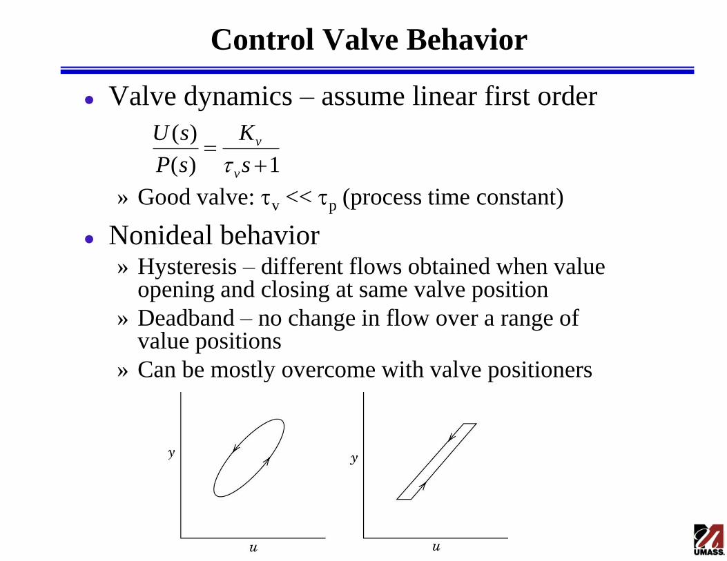
Control Valve Behavior
Valve dynamics – assume linear first order
» Good valve: tv << tp (process time constant)
Nonideal behavior » Hysteresis – different flows obtained when value
opening and closing at same valve position
» Deadband – no change in flow over a range of value positions
» Can be mostly overcome with valve positioners
1)(
)(
s
K
sP
sU
v
v
t

Sizing Control Valves
Design equation
» q = flow rate
» Cv = valve coefficient
» l = lift (amount open)
» f(l) = valve characteristic
» DPv = pressure drop across valve
» gs = specific gravity of fluid
Valve characteristic
svv gPlfCq D )(
1:percentage Equal
:openingQuick
:Linear
lRf
lf
lf

Control Valve Sizing Example
Design a linear control valve that is 50% open at the nominal flow rate for a fluid with gs = 1
Pressure drop across value: Dpv = 10 psi
Valve coefficient
1271105.0
200
)(
D
sv
vgPlf
qC