Embed Size (px)
Citation preview

www.sulzer.com
Control System Type ABS PCx
EN System Manual
8130
0046
D (0
7/20
14)

813
0004
6D
Control system type ABS PCx, System manual
Copyright © 2014 Sulzer. All rights reserved.
This manual, as well as the software described in it, is furnished under license and may be used or copied only in accordance with the terms of such license. The content of this manual is furnished for informational use only, is subject to change without notice, and should not be construed as a commitment by Sulzer. Sulzer assumes no responsibility or liability for any errors or inaccuracies that may appear in this book.
Except as permitted by such license, no part of this publication may be reproduced, stored in a retrieval system, or transmitted, in any form or by any means, electronic, me-chanical, recording, or otherwise, without the prior written permission of Sulzer.
Sulzer reserves the right to alter specifications due to technical developments.

Contents
81300046D
Table of Contents Page 1 INFORMATION ABOUT THE MANUAL ......................................................................................... 1 2 VERSION HISTORY. ....................................................................................................................... 1 3 GENERAL INFORMATION ABOUT PCX ....................................................................................... 2 4 PROGRAM STRUCTURE ............................................................................................................... 4
4.1 GENERAL .................................................................................................................................... 4 4.2 DATA SECURITY ........................................................................................................................... 5 4.3 KEYBOARD DESCRIPTION ............................................................................................................. 6 4.4 SHOW/PROGRAM ........................................................................................................................ 7 4.5 TEXT WRITING ............................................................................................................................. 7
5 CONFIGURATION ........................................................................................................................... 8 5.1 GENERAL .................................................................................................................................... 8 5.2 PUMP CONTROL........................................................................................................................... 8 5.3 PC PROGRAMS. ........................................................................................................................... 9
6 PROGRAM FUNCTIONS............................................................................................................... 10 6.1 PUMP CONTROL......................................................................................................................... 10 6.2 VALVE CONTROL PUMP AND PUMPPIT .................................................................................... 13 6.3 PUMP CAPACITY AND IN/OUTFLOW OF THE PIT ............................................................................. 14 6.4 FLOW........................................................................................................................................ 17 6.5 SPEED CONTROL OF PUMPS ....................................................................................................... 24 6.6 PID CONTROLLER ...................................................................................................................... 28 6.7 SHIFT MOTOR ............................................................................................................................ 30 6.8 REMOTE CONTROL .................................................................................................................... 30 6.9 ANALOGUE HISTORY .................................................................................................................. 32 6.10 ALARM HANDLING / TIME STAMPED EVENTS .............................................................................. 33 6.11 MODEM AND ALARM CALL ....................................................................................................... 34 6.12 LOGICAL FUNCTIONS .............................................................................................................. 37
7 FUNCTION KEYS .......................................................................................................................... 38 7.1 PUMP ....................................................................................................................................... 40 7.2 PUMPPIT ................................................................................................................................... 45 7.3 ALARM SHOW /PROGRAM ......................................................................................................... 50 7.4 DIGITAL IN ................................................................................................................................. 54 7.5 DIGITAL OUT .............................................................................................................................. 62 7.6 ANALOGUE IN ............................................................................................................................ 70 7.7 ANALOGUE OUT ......................................................................................................................... 78 7.8 FLOW/PULSE ............................................................................................................................. 80 7.9 MANUALLY CONTROLLED PUMP .................................................................................................. 83 7.10 PID CONTROLLER.................................................................................................................. 84 7.11 CONFIGURATION OF MAIN MENU .............................................................................................. 86 7.12 PARAMETERS SPECIFIC FOR USER .......................................................................................... 87
8 FUNCTION CODES ....................................................................................................................... 88 8.1 OVERVIEW ................................................................................................................................ 88 8.2 DESCRIPTION OF ALL FUNCTION CODES. ..................................................................................... 91
9 IO- AND ALARM NUMBERS ...................................................................................................... 127 9.1 IO NUMBERS ........................................................................................................................... 127 9.2 ALARM NUMBERS ..................................................................................................................... 131
10 INDEX ....................................................................................................................................... 145

System manual PCx Page 1
81300046D
1 Information about the manual
The manual is split into following parts: • Chapter 2 gives information of previous program versions. • Chapter 3 gives a brief introduction how the PCx system works • Chapter 4 describes how to configure the program. • Chapter 5 describes what to think about when programming the PCx • Chapter 6 describes how the more complex control functions works • Chapter 7 describes the program menus from the operator panels PCxop/h point of view • Chapter 8 describes the additional function codes • Chapter 9 describes the IO- and alarm numbers of the PCx • Chapter 10 is an index of this manual
2 Version history.
This manual is supporting the software version 1.2 of the PCx. New features for Rev B of this manual are:
• Ramp times for analogue outputs • New DI type, Alarm acknowledge • New DI type, Manual start of pump • Function 815, A delay between sending connect and ID string for LC- TRANSLATOR mode. • Function 829, Alarm blocking when power failure alarm is active. • Function 850, Energy save modes

System manual PCx Page 2
81300046D
3 General information about PCx
The PCx series is a control system from Sulzer. It contains three different modules, control processor unit PCx, expansion module PCxp and two operator panels PCxop.
The control processor unit is a control computer PCx. The software in the PCx supports control of water and sewage pump works, pumping pits and booster stations. The PCx can also measure and log data, receive and transmit alarms. To do this the PCx has both digital and analogue in- and outputs. The PCx has a RS232/485 port for communicate with other systems.
The expansion module is a PCxp-unit, and its function is to expand the amount of in- and outputs. The PCxp-unit has also a RS232/485-port. Up to 7 PCxp-units can be connected to one single PCx.
The PCxop is a permanent mounted panel. The functions with the operator panel are to present information about the system and to put information in and configure the PCx The communication between the modules is through a CAN-network.
The PCx can communicate with other systems through the interfaces RS232 and RS485. The PCx has built in functions for various kinds of accessories, for example modem and radio. The PCx can send alarms to supervision systems and SMS to mobile phones.
1 2 3 4 5 6 7 8 9 * 0 #
CLR 1 2 3 4 5 6 7 8 9 * 0 #
CLR 1 2 3 4 5 6 7 8 9 * 0 #
CLR

System manual PCx Page 3
81300046D
There are two ways to configure the system either by the operator panel or through a personal computer equipped with AQUA PROG software. The uplink to a computer could be a direct cable, a GSM-modem, radio or telephone-modem.
The PCx can be connected to a supervision and alarm handling system; an example is Aqua Vision from Sulzer. The communication is through the protocols COMLI or Modbus.
1 2 3 4 5 6 7 8 9 * 0 #
CLR 1 2 3 4 5 6 7 8 9 * 0 #
CLR 1 2 3 4 5 6 7 8 9 * 0 #
CLR

System manual PCx Page 4
81300046D
4 Program structure
4.1 General
The PCx is technically very advanced, which allowed us to develop a very powerful program for the control of water- and sewage works, pumping pits and booster stations. The big difference between a normal PLC and the PCx-system is the programming or more correctly said the configuration of the unit. When configuring the PCx it is not necessary to learn a programming language or to make logic drawings, you just activate the built-in control functions needed, which are pre-programmed in the unit. The larger parts in the PCx program structure are object-orientated. When the needs of more control and complex measuring as for example pump pits the configuration is mainly done via the function keys ”Pump”, ”PUMP PIT” and ”Alarm” and also if needed ”Flow”. Through the I/O keys ”Digital in”, ”Digital out”, ”Analogue in” and ”Analogue out” are the physical I/O of the unit linked to the control functions above Extra functions for the unit are made through the ”Function” key. All signals under I/O keys have specific names and will be described in this manual. All names of the predefined functions can be replaced with names that the user finds more adequate.
System manual PCx Page 5
81300046D
4.2 Data security
The PCx has 2 code access levels to prevent that unwanted changes of the program occur and a third basic level access where only the parameters are viewable. • Operator access gives the possibility to change some of the set point values like start and stop
levels of pumps but not to change the functions of the outputs. • System access gives full access to all configuration levels in the PCx. • Without an access code it is only possible to view parameters of the functions in the PCx. From factory the unit is delivered with following access codes: • Operator code = 1 • System code = 2 If these codes need to set to other values see function (F950). Independent of what menu that are viewed on the PCxop the PCx-unit continues to work as normal. If the PCxop keyboard has not been touched for 2 minutes the PCxop will automatically go back to the main menu. This means that the unit cannot be left with a system access level that can compromise the configuration of the system.

System manual PCx Page 6
81300046D
4.3 Keyboard description
Most of the keys on the keyboard have double functions depending on where you are in the menu tree. All showing and programming is done in the same way that makes it easy and fast to understand the system and use it.
Here follows a short description of the keys and its functions. Further information is available in the program module description. • PUMPPIT:
Status Pumped volume In this menu the pumped volume is shown for Pumppit 1-4 split into the last 7 days and as a total. Settings Here are the settings for the control, which are directly linked to the Pump pits. Settings for inflow calculations, overflow level and relative level. Pumppit valve Here a valve that is linked to the level in the pump pit can be configured.
• Pump: Pump status In this menu the running times of the pumps, the start counters and the calculated pump capacity for the last 7 days and as a total are found. Pump settings Here are the settings for the control parameters and functions of the pumps and the linking of the pumps to the pump pits. Pump valve In this menu you will find the settings of the control parameters and functions of valves that are connected to pumps.
• Alarm: Status Here the alarms are acknowledged and selected. Settings Here you find different possibilities to set-up alarms Set-up alarms Here only set-up alarms can be changed
• Acknowledge alarm: This key together with the arrow keys and ENTER key are used to acknowledge alarms. (Max number of alarm events in the alarm list is 500 ).
• Function: This function key together with 1-3 number code gives access to the special functions in the PCx.
• Digital in: This key is used to set the number of the Digital input to be programmed or shown the setting of.
• Digital out: This key is used to set the number of the Digital output to be programmed or shown the setting of.
• Parameters: Parameter settings of user specific data.
• Analogue in: This key is used to set the number of the Analogue input to be programmed or shown the setting of.
• Analogue out: This key is used to set the number of the Analogue output to be programmed or shown the setting of.
• Flow: Accumulated volume Here the accumulated flow for the flow and pulse channels are shown as a total value and split for the last 7 days.
• Overflow status In this menu the overflow status is shown for the last 7 days and as a total value. Actual values Here is shown the actual values for the Channel overflow measurement
• Channel flow settings. Here the Channel and overflow flowmeters are set.
• Pump Start: Her the status of the pumps is shown and the pumps can be started and stopped.

System manual PCx Page 7
81300046D
4.4 Show/Program
Show: (No access level) Press the function key in which the sub function that you want to see is. Thereafter press <ENTER> key to verify your choice. If a blinking marker is shown this means that you should either enter a value via the keyboard or step forward to next sub function with <ARROW> keys. If you enter a function window with menu choice you chose the wanted menu with the<ARROW> keys and verify with the <ENTER> key. In certain menus the <ENTER> key is used to jump to the next menu and the <ARROW> key to step around inside the menu. To get back to the main menu press <CANCEL> several times. Programming/Configure: When programming always start by pressing the <PROG> key and state your operator or system access code followed by <ENTER> to verify your choice. Then you press the function key of the sub function you want to program and press the <ENTER> key to verify your choice. A blinking marker means that you should enter a value via the keyboard or step forward to a sub function with the <ARROW> keys.. If you enter a function window with menu choice you chose the wanted menu with the <ARROW> keys and verify with the <ENTER> key. When a menu choice is a question for ex. YES/NO ( Y/N ), the <ARROW> keys are used to chose between YES and NO and the <ENTER> key to jump to the next menu. To get back to the main menu press <CANCEL> several times.
4.5 Text writing
In the main part of the functions via the I/O keys you can set your own texts Following characters are available: abcdefghijklmnopqrstuvwxyzåäö !”#$%&’()*+,-./0123456789:;<=>?@ ABCDEFGHIJKLMNOPQRSTUVWXYZÅÄÖ\ With <ARROW> keys you step forward and backwards in the characters With the <+/-> keys you step forward one position on the line.
With the <.> key you can erase character by character.
. REGU-LATOR
RESET ALARM +/-
FUNCTION

System manual PCx Page 8
81300046D
5 Configuration
5.1 General
The PCx includes many functions and this chapter will give an overview of the available functions. Before you start configuring the PCx it is necessary to know to which in- and output the different functions use. It is not necessary to configure everything before the installation of the unit; the configuration can be changed and modified at any time without any disturbances in the functions. The PCx can be configured using following steps: • I/O signals
Via I/O keys ”Digital in”, ”Digital out”, ”Analogue in” and ”Analogue out”. • Pumps
If pumps are to be controlled • PUMPPIT
If pumps are to be controlled • Alarm
If these were not already activated when setting the program functions ”Pump” and ”PUMPPIT” . • Flow
If flow is going to be calculated and stored. • Function codes
Functions that are not logically direct linked to above mentioned program modules.
How to configure these functions are described in chapter 7. In chapter 8 are the built in configurations listed that can easily be loaded and edited. Here are a very simple example on how to do an own control function for a pump pit that has two pumps and a level sensor. The sensor has a 4-20 mA range that equals to 1-3 m with P1 start level 0.7 m and stop level 1.0m and P2 start level 0.8 m and stop level 1.1m Note! This example is only for showing how easy it is to connect in- and outputs on the PCx to the control features and that the built in configurations may be much better to start with as they have many options already set, protectors, alarms etc. First connect the P1 through PUMP key menu and select pump settings-> normal operation. Step to Pump 1 and then connect it to pump pit 1. Thereafter set the start and stop levels for the P1 repeat it for P2. Configure two Digital outputs for both P1 and P2 through DIGITAL OUT key and set Dut 1 for P1 and Dut 2 for P2. Configure a Analogue input for the Level sensor through ANALOGUE OUT and set Ain 1 as Level Sensor PP 1 and configure the values for that sensor like 4 – 20 mA signal and set 4 mA equals to 0.1m and 20 mA equals to 3m. The PCx will now control the pumps in this pit as mention in the description before.
5.2 Pump control
A fast way to configure a new pumping station is to activate one of the standard configurations for 2, 3 or.4 pumps and modify the configuration to fit the specific application. To do this, look at the configuration descriptions at the end of this manual.

System manual PCx Page 9
81300046D
5.3 PC programs.
Two programs that supports the PCx is: • Aqua Prog
A program to configure the PCx from a Windows environment. For both fixed or called up communication.
• AQUA VISION A complete alarm and supervision system for ABS products. For both fixed or called up communication.

System manual PCx Page 10
81300046D
6 Program functions
In this chapter are the basics of the functionalities and properties for the PCx described.
6.1 Pump control
The PCx software is object oriented and below is the properties of a pump pit object and a pump object listed. The PCx can control up to 4 pump pits, which can be configured separately. Properties for a pump pit are:
Can control pumps, which are connected to it. The pumps can have individual start and stop levels. Can alternate between pumps in the pump pit both run time alternation and pump start alternation is available. The alternation do not need to be applied to all pumps in the pit only those that are configured to do this, an example is pump 1 and pump 3 is alternated and the pump 2 is not and is always using its individual setpoints. A delay between different starts of pumps can be set for each pump pit, an option to prohibit that several pumps starts at the same time, this function can be used to avoid heavy loads on the electric net. Can have a level sensor configured for it. Can backup control pumps if a level sensor is damaged. Can start pumps on a high inflow in order to start pumping earlier than the start level setpoint to prevent overflowing pits that do not have a large storage capacity, each pump can have its own start level. Can control valves for the pit. Can give status about overflow. Can give status about the amounts of starts and stops in a pit etc. Can have a day and night mode with different levels of operations. Can send alarms about different failures and high – low levels and many more. Can measure and calculate the in- and outflow of the pit.
The PCx can control up to 16 pumps. Some of the properties for a pump are listed here: Can be linked to a pump pit or group.
Can be controlled by an own sensor, pump pit level sensor etc. which are connected to an analogue input. Can have own setpoints for stop and start levels and these can be set to be different during day and night.
Can be speed controlled. Can control the valves to the pump.
Can have a maximum time of operation, in example if the pump runs hot after 60 min it can be set to only be run just 60 min a time. Automatic calculations of the capacity for the pump. A pump can have its own start level of the inflow to the pump pit. A pump curve can be inputted for each pump for more accurate calculations of the capacity of the pump.
6.1.1 Back - up control
As a safety against a broken level sensor a backup control function can be used. If the pump pit has a high-level float sensor fitted it can to start the pumps when the usual level sensor has been broken. It has a timer that can run the pumps after that the high level sensor has been deactivated. The timer can be set between 0 to 999 seconds. The alternation function, if it has been set for a pump, is still in use even during this back-up control. The time will be divided equally between the alternated pumps. If several pumps have been set to run with the back-up control will these start with the usual set time delay for the pump pit, even if the high-level float sensor has been deactivated during that time. A backup controlled start will be indicated in the alarm list.

System manual PCx Page 11
81300046D
6.1.2 Running indication
If the pumps are put in automatic control mode can an alarm for pump failure be received if there is a feedback indicator connected to the digital input or a current transformer connected to an analogue input.
6.1.3 Delays
Separate start and stop delays can be set for each pump. These delays are used before any alternation of pumps and work as a filter to avoid waves and other measuring disturbances affect the setpoints for the pumps. Furthermore a min. time between starting different pumps can be set. This timer is activated when a setpoint is active and blocks the start of all other while the timer is active. A min. time can be set before stopping a pump and different pumps can have different delays that prohibit the pumps to be stopped at the same time, in example when blocking a pump pit. That is used to prevent transients in the electric net, which often occur when stopping several big pumps at the same time. NOTE! External control of separate pumps comes after set-points and the alternation and is not affected by the timer for min. time between pump starts or the pump stops.
6.1.4 Blocking
A blocking signal from a digital input can be used to block the whole PUMPPIT or a separate pump Blocking of a separate pump is done without time delay. When blocking a PUMPPIT the min. times between pump stops are active.
6.1.5 Manual start of pumps
A manual controlled pump is run without alternation and time delays. A manual start via the PCxopi can only be made if the water level is between the set start and stop levels for the pump unless an external button is mounted and connected to a digital input. Eventual alternation is reset when a manually started pump stops at a stop level or a manually stopped pump starts at its start level.
6.1.6 Reset motor protector
This function can reset the motor protector automatically. When the protector has been set the PCx can automatically try up to 3 times to reset it. If not successful during the last attempt an alarm will be set, ERROR M-PROT, and manual reset of the protector must be done. Settings that can be done are a timeout from 1-999 sec and a reset pulse time from 1-99 sec. Manoeuvre via Comli/Modbus is only possible if motor protector is fallen. At Comli/Modbus manoeuvre with 0 all further attempts are stopped until the motor protector has been reset manually or a new Comli/Modbus manoeuvre is made At Comli/Modbus manoeuvre with 1 the attempt counter is set to 0 and a new resetting sequence starts. NOTE! The delay timer is executed before the pulse is sent even when using Comli/Modbus manoeuvre.
6.1.7 Reversing the pumps
This function can automatically reverse the pump. It has two different sequences that can be used. In the first sequence the function holds the pump in off position during pre-set delay time and thereafter activates another pre-set reversing output for a reversing time.
System manual PCx Page 12
81300046D
Another sequence is if a pump output is set as Pump Relay ON, the pump output will be activated 0.5 sec after the reversing output and will be closed 0.5 sec before the reversing output and thereafter the pump is blocked during the pre-set delay time before it goes back to normal running conditions. The Pump reversing can be chosen to start automatically when PCx is resetting a motor protector and the pump capacity drops below a setpoint value or via Comli/Modbus communication. A running sequence cannot be stopped via Comli/Modbus
6.1.8 Spray pumppit
This function counts the pump stops for a pump or a whole pump pit and gives an output impulse after a pre-set number. If a specific pump number is set, this function only counts the stops for the specified pump. If a specific pump pit is set, the function counts all pump stops for all the pumps in the pit. If a pulse time is set to 0 the output is active while any of the pump(s), which controls the counter, are in an OFF position after the pre-set number of stops has been reached.

System manual PCx Page 13
81300046D
6.2 Valve control PUMP and PUMPPIT
6.2.1 Pump valve
The PCx can control Pump Valves through two different functions. One uses a digital output as VALVE CONTROL and the PCx activates the output the whole time the valve shall be open (same as pneumatic valves). The other function requires two digital outputs configured as an OPEN VALVE signal and a CLOSE VALVE signal. The valves can be without end point contacts or with indication of one or both end contacts. If the pump has a running indication from a current transformer or a digital input is the valve blocked until running indication from the pump is received. When not using end contacts indication the OPEN and CLOSE relays are active during the time set in END POSITION MAX TIMES. "Pump time open" is the time the pumps are running before the valve starts opening. "Pump time closing" is the time the pump is running after closing of valve has started NOTE! Pump time can be set to be shorter or longer than valve time. When end contact is used and is reached the OPEN or CLOSE outputs become deactivated. When “end contact closed” is reached the pump will stop even if the pump time closing is not reached. If detection of the end contacts is not found within the pre-set MAX time a closing sequence will be made. Also if a closing indication is missing the pump will be blocked until the end contact is repaired If OPEN indication is missing the pump will be blocked until the set-point is OFF (New attempt will be made next time the pump starts). If both OPEN and close indication is received a closing sequence will be made and the pump blocked until the error is solved. This will be indicated by Alarm Valve error. If the CLOSED indication disappears a closing sequence will be made. If CLOSED indication does not reappear the pumps will be blocked as above. When the OPEN indication disappears the REOPEN sequence will be run for the pre-set time. If OPEN indication does not reappear the pumps will also be blocked as above. IF "Blocking at error "is set the pump is blocked until the Alarm PUMP ERROR BLOCKING is acknowledged.
6.2.2 Pump pit valve
This built in function controls the valve of the pump pit. The valve opens as soon as any of the pumps in the pit starts and is closed when all pumps in the pit are OFF. The pump(s) which is running when a start of a closing sequence will continue(s) to run for the time set in PUMP TIME CLOSING. Otherwise the function is identical to PUMP VALVE.
6.2.3 Other information
If a level controlled valve has to be connected a free pump can be used to set up the pump valve without connecting any pump to the output.
System manual PCx Page 14
81300046D
6.3 Pump capacity and In/Outflow of the pit
In a normal pump pit is the inflow calculated continuously by the level change in the pit and the outflow is calculated by the sum of the capacities of the pumps that are running. The capacity for a pump is calculated when only that pump is running. The calculation freezes the inflow value when the pump starts and thereafter the outflow is calculated during a preset time. The time must be long enough for the pump to reach full speed and for the water to reach full velocity in the pipe. These setting are found in the Pump menu. After the set delay for the start, the volume is calculated by the level difference during the measuring period. To get the real capacity, the calculated volume is recalculated to an outflow and the frozen inflow value is also added to this, if a pump curve has been inputted, will it also normalised the flow value to the lowest head of the pump. These calculations are assuming that the inflow is constant during the measuring period. The data used has to be filtered to prevent that disturbance doesn’t spoil the result of the calculation. The filter process uses one value of the last 5 measurements. The filter will first discard the 2 values with the highest deviation of the last 5 measured values then makes an average value of the remaining 3 values. Note, this means that changes in the configuration does not affect the measurements and calculations until at least 3 new calculations of the Pump capacity has been made. The last actual value is always the result of the last measurement. In the status menu for the Pump capacity both the actual and the filtered values are shown. An average value for all measurements during a day is made and is saved for 7 days. Also an average value for the week is made. Updating of all values is done after each new calculation. Each new day starts with the last actual value of the day before. The outflow of the pit is calculated when the pumps are running. It is based on the capacity for the pumps and is accumulated to a pumped volume. If a level difference in the pit, during pumping, gives changes in the pump capacity according to the pump curve, this should be set in the PCx. The outflow will in this case be compensated with the actual level in the pit according to the pump curve, which gives a more accurate accumulated volume. As the pressure losses in a pipe can be higher if more than one pump is running at the same time, there is a possibility to adjust for it by setting a capacity factor when more pumps are active. A specific factor can be set for all steps between 2- 16 pumps active. In certain situations it can be extremely difficult to achieve a proper reading of the pump capacity. Setting the measuring time for the pump capacity to 0 seconds can in this case shut off the measurement. To get a working outflow measurement in these cases, the pump capacities ( actual values)can be entered manually. In the normal case the pumps are set to EMPTY the pit. When the pumps are used in ex. water towers ,it must be changed to pumps are FILLING the pit. In this case the inflow is the sum of the pump capacities and the outflow is calculated continuously based on the level changes.

System manual PCx Page 15
81300046D
6.3.1 Pit shape
The continuous flow measurement is based on the fact that the PCx can calculate the volume by measuring the level difference during a set calculation time. For this calculation is to exact it is necessary that the area /level should be always known. This can be achieved by setting the level and area for all level where the pit changes shape, up to 9 break points + the area at zero point can be set.
To get a correct calculation at all levels even the pit shape has to be set as the calculation is different for different geometrical shapes. A shape that ends in a point is set as conical, if it ends as a wedge (2 parallel sides) it is set as rectangular shape, see figure above.
6.3.1.1 Example for area calculation:
CircelRectangel
A= L * W Ex.
A= Area A= ?L= Length L= 2,20 meterW= Width W= 1,75 meter
A= 2,2 * 1,75
A= 3,85 m2
A= pi * r2 Ex.
A= Area A= ?pi= 3,14... D= 2,50 meterR= Radius = D/2 R= 2,5 / 2 = 1,25 meter A= 3,14 * 1,252
A= 4,9 m2
Rectangular Cone Cone

System manual PCx Page 16
81300046D
6.3.2 Pump curve
The outflow from a pump pit is calculated by adding the calculated pump capacity for the pumps running. For some pumps the capacity can vary considerably depending on where the normal working range is on the pump curve. PCx can continuously adjust the calculated out flow to flow at actual level if the pump curve is available. The pump curve is set separately for each pump by setting 3 values from the pump curve. Best accuracy is achieved if these 3 values are chosen within the normal working range of the pump. The head of the pump must be known to get on the right part of the pump curve. The head is calculated from the highest point of the outlet pipe.
Actual head of pump =Total head of pump – actual level.
6.3.2.1 Example:
Setting of pump capacity is in integer l/s, which means that we have to adjust the levels to integers for the pump capacity. Above pump curve gives following flows
Head of pump Pump capacity (l/s)
Lowest level (outlet level of pump) L 18 m 8 Mid level 15.5 m 14.2 Mid level adjusted to integer flow in l/s M 15.6 m 14 Highest level in pit H 13 m 19 Head: If sensor is mounted according to Ex.1 (sensor 0-level = outlet level for pump) the head is set to18 m . Often the sensor 0-point is lower than the outlet of the pump. In this case the difference must be added to the head. The sensor according to Ex.2 is 0.4 m below the pump outlet. Head is set to 18 m + 0.4 m = 18.4 m. Sensor according to Ex.1 Sensor according to Ex.2
PUMP: 1 Pump curve 18.00 m = 8 l/s 15.60 m = 14 l/s 13.00 m = 19 l/s
PUMPPIT: 1 Flow: Head of pumps for compensation with pump curve 18.40 m
PUMPPIT: 1 Flow: Head of pumps for compensation with pump curve 18.00 m
Ex. 1
Ex. 2
Overflow at 5,00 mfrom lowest levelH=18 m-5 m= 13 m
18 mVp.
Start 1,75 m
Stop 0,50 m
Mid level 2,50 mfrom lowest levelM=18 m- 2.5 m=15.5 m
Lowest level 0 mL=18 m-0 m=18 m
0 2 4 6 8 10 12 14 16 18 20 22 24 26 28 30 l/s02468
10121416182022
Head of pump mVp.
Pumpcurve
H
M
L
Diff.0,4 m.
Head of pumps
in mVp.

System manual PCx Page 17
81300046D
6.4 Flow
6.4.1 Measuring points Open channels / Weirs
6.4.1.1 Straight weir with and without side contraction
Flow parameters for straight weir without side contraction: Q = Ce * 2/3 * 2g * be * he
1,5 • Width of weir b > 0,15 meter. • Measuring height h > 0,06 meter. • Weir height p > 0,09 meter. • h/p = 0 - 2,55 • Q = flow in [m3/sec] • Ce = flow constant, a function
of: h, b and h/p. Flow conditions: • Straight length: L > 10 * b,
If some type of dampening device is used the straight length can be made shorter.
• The channel width should be the same after the weir for a distance of: 0,3 * hmax.
• A inlet with free fall into the channel must be at least 30 * hmax in front of the weir.
Flow parameters for straight weir with side contraction: Q = Ce * 2/3 * 2g * be * he
1,5 • Weir width b > 0,15 meter • Measuring height h > 0,06 meter • Weir height p > 0,09 meter • h/p = 0 - 2,55 • b/B = 0 - 1,00 • (B-b)/2 > 0,10 metre • Q = flow expressed in [m3/sec] • Ce = flow constant, is a function
of: h, b, h/p and b/B. Flow conditions: • Straight length: L > 10 * b,
If some type of dampening device is used the straight length can be made shorter.
• b < 1 metre free fall after the weir at least 0,1 * hmax.
• b > 1 < 5 metre, min 0,25 * hmax. • An inlet with free fall into the channel must
be at least 30 * hmax in front of the weir.
STRAIGHT W
EIR WITH
SIDE CONTRACTION
M.P.=1m, m
in. 4 * hmax
hmax
STRAIGHT W
EIR
M.P.=1m, m
in. 4 * hmax
hmax

System manual PCx Page 18
81300046D
6.4.1.2 V-notch weir and special v-notch weir in a measuring chamber
Flow parameters concerning V-weir (Thompson): Q = Ce * 8/15 * tan(@/2) * 2g * he2,5 • Angle in degrees @ = 20 - 100 • Measuring height h >0,06
meter • Weir height p >0,09 meter • h/p = 0,1 - 2,00 • p/B = 0,1 - 1,00 • Q = flow expressed in m3/sek • Ce = flow constant, is a function
of: h, @, h/p and p/B. Flow relationship: • Straight length: L > 10 * b,
If some type of dampening device is used the straight length can be made shorter.
• If B/b > 3 or hmax/p < 1 the distance can be reduced.
• A inlet with free fall into the channel must be at least 30 * hmax in front of the weir.
Flow parameters concerning special V-weir (Thompson) special: Q = Ce * 8/15 * tan(@/2) * 2g * he
2,5 • Angle in degrees @ = 20 - 100 • Measuring height h > 0,06
meter • Weir height p > 0,09
meter • h/p = 0,1 - 2,00 • p/B = 0,1 - 1,00 • Q = flow expressed in m3/sec • Ce = flow constant, is a function • of: h, @, h/p and p/B. Except for above, the following should be taken into consideration: • The pipe diameter D = 0,8 * hmax • p + 0,55 * D = a = 0,6 * hmax + 0,5 * D • 2 * hmax = M.P. = 4,9 * hmax prefer-
ably choose M.P. = 4 hmax • B = 3,2 * hmax
W-NOTCH WEIR
M.P.=1m, min. 4 * hmax
hmax
B@
b
>2hmax >5hmax >2hmax
M.P.
hmax
0,8hmax
D
p>1,6hmaxa
Retension wall over the hole width

System manual PCx Page 19
81300046D
6.4.1.3 Parshall and Venturi flume
Flow parameters concerning Parshall flumes: Q = Ce * b * hexp • Q = flow expressed in m3/sec • Ce = flow constant, is a function of among
other: b/B. Varies between 2,316 (3") - 2,367 (36")
• b = contraction width • B = channel width • Exp. The exponent varies between
1,547 (3") - 1,566 (36"). • hmax 0,8 * B Flow relationship: • Straight length: L > 5 * B,
If some type of dampening device is used the straight length can be made shorter.
• The channel gradient should be less than 0,1 - 0,3%.
• A inlet with free fall into the channel must be at least 30 * hmax in front of the weir.
Ce and exp. are programmed in the LF/LPF for the different channel widths. Flow parameters concerning Venturi channels: _____ Q = 2/3 V 2/3g Cv Ce b h1.5 • Q = Flow expressed in m3/sek • g = 9.8066 • Cv = Flow constant, is a function of::
b/B > 0.3, b/B < 0.70 • Ce = (b/(b + 0.004 L)) ((h - 0.003 L)/h) • b = Contraction width • B = Channel width • L = Contraction length > 1.5 hmax h = Level < 3 b Flow relationship: • Straight length: L > 5 * B,
If some type of dampening device is used the straight length can be made shorter.
• The channel gradient should be less than 0,3 - 0,5%.
• A inlet with free fall into the channel must be at least 30 * hmax in front of the weir.
LM.P.=2/3L
PARSHALL FLUME
M.P. MEASURING POINTMOUNT SENSOR IN MEASURINGCHAMBER IF AVAILABLE
B b
M.P.=3*hmax
hmax
CHAMBER IF AVAILABLEMOUNT SENSOR IN MEASURINGM.P. MEASURING POINT
VENTURI FLUME
bB

System manual PCx Page 20
81300046D
6.4.1.4 Palmer Bowlus flume
Flow parameters concerning Palmer Bowlus flumes: • hmax for PB with pipe connection is 0,9 *
D. • hmin = 0,05 metre or 0,05 * D. • hmin when D < 0,3 = 0,03 metre. • hmin at polluted water 0,2 * D. Flow relationship: • Straight distance L > 6 x D.
If any kind of flow dampening device is used the distance can be shortened.
• The channel gradient should be less than 0,1 - 0,3%.
• An outlet with a free fall into the channel should be at least 30 * hmax before the flume.
Use function "Known values" for calculation of PB flumes according to the table below.
M.P.= Di/2
Di
PALMER BOWLUS FLUME
M.P. SHOWS THE MEASURING POINT.
1
2
3
4
5
6
7
8
1
2
3
4
5
6
7
8
1
2
3
4
5
6
7
8
9
1 1 1 1
2 2 2
2
3 3 3
4 4 4 3
5 5 5
6 6 6 4
7 7 7
8 5
8 8
6
9
7
8
4" 18"6" 8" 10" 12" 15"m
l/sec
l/sec
l/sec
l/sec
l/sec
l/sec
l/sec
l/sec
l/sec
0,01
0,02
0,03
0,04
0,05
0,06
0,07
0,08
0,10
0,12
0,14
0,16
0,18
0,20
0,24
0,27
0,30
0,33
0,36
0,10
0,31
0,64
1,09
1,64
2,33
3,15
4,07
0,14
0,42
0,82
1,34
1,99
3,70
7,46
10,58
0,18
0,54
1,05
1,69
2,46
4,46
8,70
12,47
21,66
0,66
2,04
4,02
6,64
9,95
19,01
37,85
37,85
1,00
2,50
4,62
7,37
10,87
20,37
33,75
58,30
1,10
2,75
5,25
8,75
13,00
23,75
38,75
68,00
104,0
1,15
3,82
9,50
24,75
46,87
85,07
131,9
165,0
Nr.
Nr.
Nr.
Nr.
Nr.
Nr.
Nr.
Table over values to be set in function "known values"for PALMER BOWLUS FLUME
l/sec
l/sec
l/sec
l/sec
l/sec
l/sec
l/sec
l/sec
l/sec
l/sec

System manual PCx Page 21
81300046D
6.4.1.5 Flow measurements in a pipe
The PCx can measure the flow in a pipe if a velocity sensor and a level sensor is attached to it. The diameter of the pipe is configured in the FLOW key. The Velocity sensor and the Level sensor is configured on the ANALOGUE key. To configure a pipe flow measurement press the FLOW key and select a Flow channel (1-4), then select Pipe flow, set the diameter and what analogue input is used by the velocity sensor. Then configure the analogue inputs. See below for more info.
Diameter
Pipe
V (m/s)
Leve
l (m
)
The flow key settings.
Select a flow channel and then pipe flow. Then set the diameter of the pipe and last select the analogue input used for the Speed sensor.
The analogue key settings.
Select the input that has the level sensor and select Channel flow. Select the input with the speed sensor and select Free-choice. Type in the unit m/s (it must be a meter per second signal or scaled to that.).
Now it is finished and the measurements should be active.
5 Flow ch 1 : Pipe Flow Pipe dia. 2.000 m Speed sensor=A.in1:2
IO-module:1(1) Ain:1 mA input Channel flow Flowmeter no.1 IO-module:1(1) Ain:2 mA input Free-choice Unit: m/s 2 decim.

System manual PCx Page 22
81300046D
6.4.2 Overflow flow measuring
There are several methods that can be used to measure and calculate overflow flow: 1. Use a weir and a conventional flow meter. Advantage: In most cases for standard PLC-systems will it increase the accuracy on the
measurement. Drawbacks: Expensive and on sensors that only measure the overflow can dirt and mud dry on it,
when the pit is operating in normal conditions. The sensor has to be cleaned regularly to ensure correct measurements.
2. Use the same sensor that is used for the level measurement in the pit and a weir and start the flow measurement on analogue setpoint. Advantage: The investment cost is low and the sensor will not need to be cleaned regularly. Drawbacks: The system must have a very good resolution on the input to be able to measure the
overflow correctly and a very accurate 0-point otherwise the measurement is wrong.
3. Use the same level sensor that is used for the level measuring in the pit and a weir and use a level switch to start the overflow measurement. Advantage: The Investment cost is low and the sensor needs not to be cleaned regularly. The
accuracy of the 0-point is not affecting the measurements due to that the switch is used as a 0-point.
Drawbacks: The analogue input needs to have a very good resolution to be able to measure the signal. The PCx has no problem with this in ex. A Sensor with the range of 10 meters the PCx has the resolution of < 0.7 mm.
The third method is used in the PCx A digital input indicates if an overflow is occurring independent of what the level signal shows. The PCx locks this actual level and the PCx starts calculating the overflow level / flow from this value. This means that the level is measured with a very high accuracy with a right 0 - point. If an exact flow measurement is needed a weir or channel should be used. The PCx program has all the functions available for calculating flow in weirs and channels. The overflow is measured separately for each pump pit. Number of overflows, overflow time and overflow level and the flow are logged.
The levels sensor is used as the actual level signal when the switch is activated it sets the 0 - point for the flow measurement. If no level switch is connected to the PCx the 0- point for the overflow can be set in "PUMPPIT / Settings / Options / Overflow" manually. Overflow will be registered when the level exceeds pre-set overflow level on the usual level sensor. NOTE! This setpoint has no function if a digital input (Overflow switch) is set for overflow indication in the pump pit.
P1 P2
INFLOW
OVER- FLOW

System manual PCx Page 23
81300046D
A delay can be set to prevent disturbances and that waves trigger the switch. After this delay the flow measurement starts and the time of the overflow is recorded. A counter keeps track of how many times the pit has overflowed. The overflow time is only trigged when the level is higher than the stored ( set ) 0- point . If a float sensor is used for a pump pit, which has no level sensor, the overflow time counts all the time the float is active. The overflow alarm will stop after the float goes back to normal and the stop delay to avoid errors in the counter and to compensate for the start delay. NOTE! If no alarm for the overflow is used will not the PCx register an overflow.
6.4.3 Ext. Flowmeters with mA.output.
Existing Flowmeters can easily be connected to the PCx.
6.4.4 Ext. Flowmeters with pulse output.
PCx can add and calculate digital pulses from sensors.

System manual PCx Page 24
81300046D
6.5 Speed control of pumps
PCx has a built-in logic for PID or P-BAND control of speed controlled pumps For pressure boosting the PID control is used for holding constant pressure in the pipeline. In pump pits PID control can be chosen if the level should be kept at a precise level, alternative P-BAND control for equalising the flow for ex. in the last pit before a treatment plant.
The speed control works with one speed controlled pump and, if more boost is wanted, more fixed speed pumps. This means that when the speed controlled pump can’t keep up pressure or flow a fixed speed pump is started and the speed of the speed controlled pump reduced to accommodate the increased pump capacity. This is called a pump group in the PCx program. The control signal (Output signal PID controller or set level range for P-BAND) is automatically divided for the number of available pumps, which are not set blocked. The automatic alternation of the fixed speed pumps is set individually for each pump as mentioned earlier. The speed controlled pump can be shifted via a built-in week timer on pre-set days and times. Possibility to connect separate pressure sensors on the suction and pressure side and to set a highest allowed pressure difference between them with an automatic limitation of the output signal when the suction pressure is dropping (The output signal can be set to limited to the difference + suction pressure). A setpoint can be used for blocking the pump when too low suction pressure is obtained. A setpoint for min. speed for a pump can be used when running a speed-controlled mode. A ramp up/down time can be used for increasing / decreasing the speed of pumps. A separate start-up ramp for slow filling of piping at start-up of booster station. When controlling a pump pit with speed-controlled pumps can sometimes cause settling in the pit and can clog the pipes if the speed of the pumps is low and therefore a low flow during long amount of time. To avoid this from happening can the pumps be controlled via extra level set-points for start and stopping the pumps. If the start set-point value is set higher than the normal set point the controller will speed up the pump every time the pump starts. To avoid long running times at low flows there is a possibility automatic lock the pump on a pre-set speed to empty the pit if the pump has been working in set minimum speed for a certain time.
P 1
P 4
P 3
P 2
Control signal 100 %0 %

System manual PCx Page 25
81300046D
6.5.1 Function codes for speed controlling parameters.
6.5.1.1 F.600
Ramp times for 0-100 % speed (0 - 999 seconds). Separate values can be used for increasing or decreasing the speed. Furthermore a start-up ramp time can be set. The start-up ramp is active until the pressure has reached the set-point or until set ramp time multiplied with the number of pumps is reached. For ex. the pit has 3 pumps and the start-up ramp time is set to 500 seconds. After max. 1500 seconds (500*3) i.e. about 25 minutes the controller will switch over to the normal ramps for increasing / decreasing speed.
6.5.1.2 F.610
Control via extra level set-points (ON / OFF).
If this set to OFF (like in booster stations) a minimum speed for the speed controlled pump can be set. The speed controlled pump is stopped, if no fixed speed pumps are running and the speed goes below a pre-set low speed.
If this setting in ON PID or P-BAND (like in a pump pit) the level set-points and minimum speed for a low flow can be set. When the pump has run on minimum speed for a set time a pre-set value for locked speed is switched on (Must normally be higher than minimum speed). The locked value is switched off if the start set-point is reached. If locked speed is set to 0 the function is not used. For a position ”ON P-BAND” the working range for the available pump capacity must be set, the PID controller is not used in this case.
Pressure inA.in 2
Pressure pipe
Suction pipe
Pressure outA.in 1
P 1 P 2 P 3 P 4
P 1 P 2 P 3 P 4
Level sensorA.in 1

System manual PCx Page 26
81300046D
6.5.1.3 F.620
Week timer for alternation of speed controlled pump. A time is set for each day (Monday-Sunday) if the no alternation is wanted the time should be set to 0:00. The alternation of speed-controlled pumps is only used on pumps that are set to be speed controlled.
6.5.1.4 F.630
An option for manual set the actual speed-controlled pump.
6.5.1.5 F.640
Max. difference between the suction side and pressure side. Will compensate the set point value when the suction pressure is decreasing. If no compensation of difference is used it should be set 0, or no analogue signal is set as signal for suction pressure for the pumps.
6.5.1.6 F.650
This function can block a pump when too low suction pressure is obtained. If any value is set accep pt than 0 is set, the PID controller is blocked if the suction pressure goes below the set-point level.
6.5.1.7 F.660
Limiting PID signal during switching of fixed speed pumps? (NO/YES). Without limit the PID controller continuous to work during the time delays for pump switching. This gives the fastest adjustment at large flow changes, but can lead to unwanted start and stops. If YES, the PID controller is limited at 10 percent over /under speed when the delays for start/stop of the pumps is active. This gives a better feedback to the speed controlled pumps but can lead to longer times to reach the set-point value at large changes in the flow.
6.5.1.8 F.702
Automatic alternation at pump failure. If fixed-speed pumps are used in a speed-controlled pump group this function should be set ON.
6.5.1.9 F.705
Min. time between every change of the pump output signals. This is the only pump related timer which is activated when pumps are blocked (for ex, Hand,0,Auto) and should be set ON to avoid unnecessary pump starts and stops , by giving the controller time to adjust for the new parameters and situations..
6.5.2 General settings
The settings that are for ON - OFF control and are applicable for speed control are made in the Pump and Pump pit menus. For ex. min. times between Start - Stop are made in "Pump_pit/Settings/Times/Start-stop delay" and ”Pump/Pump settings/times/Delay”
6.5.3 Related analogue input types:
The analogue inputs on the PCx can be configured as different objects. The whole list of them is in chapter 7.6.and here some brief info also listed.
6.5.3.1 Outgoing pressure:
Pressure sensors that can be chosen for pump group 1-4. This type is not allowed together with type Level sensor for the same pump group. Pump group 1 and 2 can either be controlled with an ON-OFF control or controlled by the PID controller. The PCx controls the actual pressure and uses the available capacity of the pumps to reach the set-point value in the PID controller. NOTE! Pump group 3 and 4 can only be controlled with ON-OFF control.

System manual PCx Page 27
81300046D
6.5.3.2 Suction pressure:
Measures the pressure before the pumps and gives the possibility to limit the set-point value at a too low suction pressure.
6.5.4 Related digital out type: Speed controlled pump
An output is set for each pump that is going to be controlled via a common frequency changer. Only one of these outputs is active for connection of the pump to the frequency changer (Hardware interlocking should be made). See below.
6.5.4.1 Setting: "Pump running controlled by this relay?" YES/NO.
If "NO" is set the output of this relay for the actual sped controlled pump is always closed and the on –off function is made by the normal pump relay. If "YES" the relay is only closed when the pump is speed controlled and the normal pump relay for the same pumps always open when the pump is speed controlled. NOTE! When changing these settings both the pump relay and the relay for speed can close! Interlocking must be done if this is not allowed in the cabinet. Pumps controlled via this relay? = NO
Pumps controlled via this relay? = YES
NOTE! This setting must be done for each output that is set for speed control.
Frequency-converter
D.out 1Pump 1
D.out 5Speed controlled
pump 1
D.out 2Pump 2
D.out 6Speed controlled
pump 2
D.out 3Pump 3
D.out 7Speed controlled
pump 3
D.out 4Pump 4
D.out 8Speed controlled
pump 4 230 VAC/400 VAC
230 VAC/400 VAC
Frequency-converter
D.out 1Pump 1
D.out 5Speed controlled
pump 1
D.out 2Pump 2
D.out 6Speed controlled
pump 2
D.out 3Pump 3
D.out 7Speed controlled
pump 3
D.out 4Pump 4
D.out 8Speed controlled
pump 4
230 VAC/400 VAC
230 VAC/400 VAC

System manual PCx Page 28
81300046D
6.6 PID controller
The PCx have 2 PID controllers. The built-in PID controllers are available under function key REGULATOR. These can be used when a constant pressure, level, flow is needed. The actual value is often an analogue input signal that should be controlled. The set-point value for the PID controller can be a manually set value, a remote controlled or an analogue in signal. The controller signal (true or inverted signal) can be connected to a mA output or used internally by the PCx as set-point value for shifting motors or as in signal for speed-controlled pumps.
6.6.1 PID-parameters
The function of a controller is mainly based on the basic PID parameters.
6.6.1.1 P amplification
The parameter P is the amplification of the controller. If actual value and set-point value is not the same there will be a deviation that is multiplied with the set amplification of the controller. The result will be the output signal from the controller. If the I time and D time = 0 the controller works as a normal proportional controller. The integrating and derivation functions are closed when they are set to 0. When P-band controller is used, there will be a fixed deviation depending on the set amplification. If the amplification is increased the output signal from the controller will increase and the fixed deviation will be smaller. This works well if the actual value is fairly constant. With a high amplification and high variations in the measured, actual, value there will be a risk for overcompensation of the output signal. If this occurs the actual value will start to fluctuate around the set-point value. If the amplification is not set too high the fluctuation will stop after a while and the output signal will stabilise. If the amplification is too high the fluctuations will not stop. This is the disadvantage of only using the P-band controller. Using the integrating function of the controller can solve this problem. (I-time). I time A PI controller has the P amplification connected in parallel with an integrating link and the sum of the two values is the controller output signal. A controller with this function is called a proportional-integrating controller. Integration is a mathematical expression that means adding. In this case the time is added which makes that the output signal from the integrating part groves with constant speed if the deviation remains constant. At normal control the deviation decreases because the controller output signal changes the actual value and the signal from the integrating part decreases and will have a constant value when the deviation is zero. The integration time is set in seconds and is defined as the time it takes for the output signal to go from 0% to 100% at 100% deviation with the amplification set to 1. The advantage of a PI controller is that the output signal from the I part totally eliminates the fixed deviation that a P controller has. This gives the possibility to lower the amplification of the controller and by this get a more stable process can occur as if too high amplification is used i.e. oscillation around the set-point. The speed of the change in the output signal will in this case be so high that the actual value can’t stop at zero deviation but overshoot. The controller in the PCx has a special damping that normally prevents overshooting. At very short I time the actual value will fluctuate around the set-point. If the I time is set too long the controller will not cope with fast changes of the actual value. Adding a derivation function can however sometimes solve this problem.

System manual PCx Page 29
81300046D
6.6.1.2 D time
A PID controller has the P and I parts coupled in parallel with a derivation part, which output signal is added to the signal from the P and I parts to give the controller output signal. A controller with this function is called proportional-integrating-derivation (PID) controller. With the derivation function the speed of change of the actual value is detected i.e. the slope of the of the actual value. (derivative) The controller will give a big change for a short time when a change of the actual value occurs.. When the change has stopped (derivative = 0) the influence of the D parts decreases and will finally stop. The D part makes the controller faster to react on changes of the actual value and can when correctly set be stabilising for the process. The effect of the D function is decided by the set D time. A short D time gives a small out signal change of short time while a long D time gives a large out signal change long duration. If the D time is set to 0 the D function is closed. The D time is defined as the width (pulse time) of the derivative impulse (on the output signal) when it has dropped to 63 % if its max value after a change in actual value. The D time is more difficult to set than the I time. Wrong set D time easily gives fluctuation around the set-point. If problems occur it is better to close the D function. (D time = 0 s).

System manual PCx Page 30
81300046D
6.7 Shift motor
This function is used for the control of for ex. valves with increase-decrease pulses on a digital output and a measured position can be returned via an analogue input (actual value). The value can be manual, remotely set or an analogue input signal. Max. 4 Shift motors can be controlled by the PCx. To avoid small position adjustments, which can damage the mechanical parts, a dead zone can be set. The PCx will not send control impulses while the set-point deviation is smaller than the set dead zone. Status menu and settings for shift motors are in F.720.
6.7.1 Related outputs
6.7.1.1 Shift motor INCREASE and DECREASE
Digital outputs can be set as Increase or decrease and the PCx will send control impulses with a pre-set pulse time and a min interval between the impulses. Reached set-points and/or position stops the control impulses.
6.7.2 Related inputs
6.7.2.1 Shift motor Max and Min
Digital inputs can be set as End position indication for a shift motor to stop impulses and to allow an alarm to be set if the analogue input, actual, value and pre-set, known, value for an end contact differs.
6.7.2.2 Block shift motor
A digital input can be set to block a shift motor output, in example when a Hand-Auto switch is used.
6.7.2.3 Force shift motor
A digital input can be set as force shift motor. If the PCx receives a signal on that input, the function will use a set point value and control the shift motor to that position.
6.8 Remote control
6.8.1 Comli/Modbus master
For controlling other PCx- units or devices, the PCx can be configured to be a Comli/Modbus master. A timer event or an I/O event can activate the Master function. In the meantime the PCx works as a normal slave unit. NOTE! Only one master is allowed on a fixed line.
If a central control system is connected will the central system normally be used as master.
Up to 8 master channels can be set up where Comli/Modbus slave identity and eventual tel. no. are set up for each channel. Up to 127 Comli messages can be set and up to 127 Modbus messages can be set.

System manual PCx Page 31
81300046D
For each message is stated: IO type: which can be as follows:
• Inactive. • Digital IO. (Message type 0 - 3). • Standard Dataregister. Reg. 0-3071 (message type '0' and '2'). • Cross ref. register. As standard but gives scaling possibilities.
See Comli/Modbus register manual about cross ref. register.
• Extended Comli register. Reg. 0-65535 (message type '<' and '=').
Local IO or register no. for IO types: Read/write: "Read from" or "Write to" slave. Master channel: 1-8. controls which slave the Master shall communicate with. IO or register or no. in slave: The master controls messages in number sequence (1-127) and where this is possible several messages are collected into only one telegram to send. In order to limit the number of Comli/Modbus telegrams, the data that is in sequence in a slave should therefore also be placed in sequence in the master configuration. If an error occurs when trying to communicate with a slave, the telegram will be resent once. If also that telegram gives an error, the communication for that actual channel will stop and an alarm for communication error will be trigged. But a new attempt will be made the next time the master communication is trigged
6.8.2 Trig of Comli/Modbus master
Under configuration of Com.-master channel the desired interval between communications can be separately set for each master channel. If 0 seconds is set the timer function is closed Furthermore each IO-number between 0-511 can be set to trig the master communication each time the status for the IO number is changed. The IO-trigger always effects all master channels.

System manual PCx Page 32
81300046D
6.9 Analogue history
Up to 32 analogue signals can be logged at the same time in the PCx. The log interval can be between 2 seconds and up to 6 hours. The types that can be logged are Actual value which logs the actual measuring value, average, Min and Max value during the log interval. The resolution of the log data can be set as16 or 32 bit value. The data are stored in a compressed format in the PCx and the maximal amount of historic data can vary with the compression factor, which can be increases if the log signals have less variation. When the data is logged the signals are divided into blocks, where each block equals 1 day of normal logging. The maximum amount of blocks is 100 (about a quarter of a year with normal logging) for each signal, which is stored in the PCx. Block 0 is always active as log block, block 1=yesterdays log data a.s.o. Older blocks are always moved on step when a new block is created. When 100 blocks are reached for a channel the oldest block will be erased before the next one is moved up. If many signals are logged with short intervals the memory may not be big enough to save all data for 100 days. The PCx automatically erases the oldest blocks if the memory starts to be full, to avoid loss of ongoing data collection. The same signals can be logged with different time intervals on different log channels. A new log block is always started at midnight. Log values from midnight to actual time for activating are set to 0 in the block when the block is activated manually. The historic data can be downloaded from the PCx by AquaVision or AquaProg system. The latest 24 hours can be read from data register also see next chapter. To view the data on the PCxop use F410 (see page 94).
6.9.1 Expanded analogue history
With the expanded analogue history there is a possibility to select a day and read 24 hours of the analogue history with the expanded Comli telegram. The F.401 must be used to set up the channels for this feature. The register area for expanded data is reg. 16384 - 32767. This allows maximum 16384 log values to be read. The start register holds the first log value for the day and the following values in sequence. At for ex. 6 min logging interval the start register is at 0;06 o’clock (min, max or average is the value between 0;00-0;06 logged) and the next reg. data is at 0;12 o’clock a.s.o. until 24;00. The start register for each channel must therefore be set according to set log interval. If the start registers for different channels overlap each other will the data for the lowest channel number will be returned and the data from the higher channel number is inaccessible. The start register for channels not used must be set to 0. Information about how many values are available for the present day can be found in reg. 12050-12069 (reg. 12050=number of values for channel 0, 12051-69 for channel 1-19 a.s.o.) The information for log channels 20-31 is located in register 13846-13857 Yesterday’s values are returned for register numbers that are higher than for present day. Missing data gives 0 when reading. Which day that shall be expanded is selected in function F401 or controlled with register 13858-13889 for log channels 0-31, with the value 0 for today and 1 for yesterday a.s.o. In the PCx there is a possibility to choose to log 32 bit data. If the log channel is set for 32-bit logging each log value will be placed in 2 registers (same as handling with double register in the PCx). At for ex. 6 minutes logging 480 registers will be used for a day at 32-bit log, and 240 registers at16-bit log allocated. For the 32-bit read out to work correctly, the register address in the Comli telegram AND the start address for the 24h history must always be even and the required number of bytes in the Comli telegram must be dividable by 4.

System manual PCx Page 33
81300046D
6.10 Alarm handling / time stamped events
The PCx stores the last 4096 events in the memory. An event can be either an alarm or an in-/output changes status, for ex. storage of start-/stop times for a pump. The logging of alarms is automatically activated while the in the I/O logging must set to activated and is set separately for each I/O event. An event is registered with date and time when the alarm is: • Activated • Inactivated • Acknowledged ( 3 events for an alarm cycle) An event is registered with date and time when an I/O is: • Activated • Inactivated ( 2 events for an I/O) The number of alarms in the log depends, as said above, on if the I/O log is activated and how many I/O is to be registered. The alarm list shows, depending on configuration, if the alarm in the list is locally acknowledged and by whom or remote acknowledged by for ex a central control system. Different access levels can be set to the function ”Acknowledge alarm”, they are listed below. • No access level required • Operator access level required • System access level required • 9 personal codes The control computer has 2 diodes for indication of A-and B-Alarm. C-Alarm is only shown in the alarm list. LED –alarm indication: • When an alarm is not acknowledged, not necessary active at the present time, the diode flashes. • When an alarm is acknowledged but still active, the diode is still lighten. • When an alarm is acknowledged and is not active, the diode is turned off automatically. • If alarm dial-up is pending when all alarms are in off state, the diode will flash slowly (for 1 second it
is on and then off for 3 seconds) until the dial up is completed successfully.

System manual PCx Page 34
81300046D
6.11 Modem and alarm call
The PCx have several possibilities to send alarms. If the PCx are connected to a central supervision system, the first call is normally made to this system. If not a connection can be established to the supervision system further attempts can be made with pagers and/or GSM telephones. The first connection can be routed to an alarm receiver of free choice.
6.11.1 F. 810 Hayes init. before call
With this function the Hayes string to be sent to the modem before the call is made, can be set and tested. The Hayes string can be up to 20 digits. The initial AT is not needed to be set. If an error in the string occurs and not an OK answer from the modem is received, the call will be stopped. Before the own Hayes string is sent, the PCx always sends a default string, which is "ATH0E0V1Q0" i.e. telephone on hook (h0), echo off (e0), text result (v1), result codes on (q0). These basic settings are needed for a good function and should not be changed.
6.11.2 F. 811 Hayes reset after disconnect
With this function the Hayes string is sent after disconnect to the modem can be set and tested. Default settings for this function is "ATQ0&W" i.e. result codes on (q0), and save all settings permanently (&w). This function gives a possibility for ex. to shut down resulting codes ("q1") after alarm call , which can be desirable in certain applications. NOTE! "q1" can never be used if CALL SIGNAL is used to acknowledge an alarm.
6.11.3 F. 812 Number of call signals before modem answer.
With this function the number of call signals before the modem answers is set. This function MUST always be set if modem is connected to the PCx. The reason is that this value, for the number of call signals, also is used for the initiation of the modem according to F.813
6.11.4 F. 813 Modem initiation.
If alarm calling is set (F.815) this function is automatically performed every 3:rd hour after that the latest data communication with the PCx. Use function F.813 to do this initiation manually. At initiation the power to the modem is first turned off for 4 seconds. The RTS signal goes low during this time. The power is switched on again to the modem. After 2 seconds the default initiation for the modem is done and if GSM modem is used the PIN code is sent. Then the number of call signals(F.813) and finally the Hayes reset(F.811) is sent.
6.11.5 F. 814 Max number of attempts to send alarm calls.
Max number of attempts to try to send an alarm call. For each new alarm that the PCx receives and that is going to be sent this counter is set to zero. Default number of attempts is 20.
6.11.6 F. 815 Alarm calls
When a new alarm is raised in the PCx, it tries to call the first alarm telephone number. If this fails after 3 attempts, 3 new attempts are made to the next alarm telephone number a.s.o.. Closed telephone numbers in this list are disregarded. This continues until the set max number of attempts in function F.814 is reached. If a central supervision system is used, this normally is the first alarm telephone number and the following numbers can be used to call different persons if the supervision system is offline. Total amount of telephone numbers that can be set is 4. For each number following alternatives can be set.

System manual PCx Page 35
81300046D
6.11.6.1 F.815 Possible alarm services
CLOSED Number unused. GSM/BEEPER (UCP) See also F.820 and F.821
Sends alarm as SMS text messages to GSM cellular phones with UCP protocol (Universal Computer Protocol), supported by a many of the leading GSM operators in Europe.
OPTIONS: Max no of messages to transfer / alarm dial. This value differs between operators and must be correct to prevent missing alarms.
CENTRAL SYSTEM For central monitoring and alarm systems. OPTIONS:
1. 2.
Alarm condition for alarm dialup. Timeout for central system to acknowledge the alarm dial. PCx will disconnect and make a new alarm dial if no acknowledge is done within this time.
LC-TRANSL.SYSTEM After connect PCx will send the Comli/Modbus identity as a text string.
Otherwise the same as CENTRAL SYSTEM. MINICALL TEXT Se also F.822 and F.823
Text beeper alarms according to the THS-protocol ver. A 3.0. Only used in Sweden.
SMS GSM MODEM (PDU) Only if GSM modem is connected to PCx
Sends alarms as SMS text messages direct to a GSM cellular phone. Phone number must be entered in international format with leading country code. Every operator also has a unique service address (Short Message Service Centre) that must be entered in international format. This service requires GSM modems with support for SMS text messages in PDU format (like PC-Card V.dot GSM-RS232, Siemens M1 or M20).
6.11.7 F.816 Waiting time between alarm calls
When an error in the modem-Tele communications occurs or no alarm acknowledgement is received, the PCx disconnects the modem and makes a new attempt after this set time.
System manual PCx Page 36
81300046D
6.11.8 F.817 Chose type of acknowledgement to stop alarm calls.
Local alarm acknowledgement and writing through COMLI/Modbus to Reg. 333 or. IO-no 511 always acknowledges the alarm call. If telephone number 1 in F.815 is the CENTRAL SYSTEM or LC-TRANSL.SYSTEM the writing to Reg. 333 is set automatically as this is demanded by supervision systems. For other alarm possibilities there are following alternatives. No acknowledgement: If the PCx succeeds to transfer the alarm information to computer of the
alarm operator the alarm is directly acknowledged. If there is an error in the alarm communication the PCx will continue to call until correct communication with the alarm operator is established.
Ring signal: The PCx listens for a ring signal from the modem after that the alarm has
been sent and this alarm is acknowledges by the call on the first CALL signal. NOTE! HAYES INITIATION must allow for verbal answering codes from modem.
Write to Reg. 333: For Central system. If a 1 is written, the Central system takes the
responsibility for disconnecting the line between them. For all other values the PCx disconnects the line directly after writing is done, this function is duplicated on IO 511
All Data communicaton: Acknowledges a call as soon as an approved Comli/Modbus telegram is
received on the modem port.
6.11.9 F.818 Acknowledgement of local alarm list from supervision system.
An alarm acknowledgement on a call acknowledges that the alarm has been received. From a central supervision system there is a possibility here to at the same time acknowledge all alarms in the local alarm list of the PCx.
6.11.10 F.819 Stations identity.
Here the number that is reported at alarm calls to GSM or pager is set. This number is also used for identification by the supervision system via Data reg. 584. If the station name is set will this also be sent to a text receiver.
6.11.11 F.820 Sender information for GSM alarm (UCP protocol)
Depending on net supplier. Senders telephone number or number received from supplier plus a password if supplier demands this.

System manual PCx Page 37
81300046D
6.11.12 F.821 Receiver information for GSM alarms (UCP protocol)
When the PCx will report an alarm, it will try to dial each receiver 3 times. When new alarms is raised it will always start with the first receiver. Disabled receivers will be ignored. When the telephone list in F.815 is finished it will start with the next receiver in this list. This means only one receiver will be called on each function call on F.815. Four receivers can be configured with following options. DISABLED Unused. TEXT GSM cellular phone with SMS text support
OPTION: Send "Only station ID" or Send "Alarm specification".
NUMBERS For future use TONE For future use The format for telephone numbers differs between operators. Some demands national format and other require international format.
6.11.13 F.824 Hold alarm dial when visiting the station.
This function does only apply if a digital input is set-up for personal alarm. An alarm call for personal alarm will only occur if the hold function is enabled. Other unacknowledged alarms will be sent when visiting indication ends.
6.12 Logical functions
The PCx can be programmed with own logical control functions. The functions used is IO-bit and logical IO. These are connected to a digital output and to fetch information about the system see chaper IO- and alarm numbers and more information about these functions can be view in the next chapter.
6.12.1 Logic IO
For logic conditions on 1 to 5 IO numbers of free choice and the following conditions can be set: ”OR ON”, ”AND ON”, ”OR OFF”, ”AND OFF”.
6.12.2 IO-bit
Used to connect an IO number of free choice to an output signal either as a pulse when the IO goes active, or with a start and stop delay.
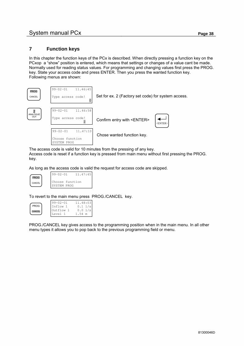
System manual PCx Page 38
81300046D
7 Function keys
In this chapter the function keys of the PCx is described. When directly pressing a function key on the PCxop a “show” position is entered, which means that settings or changes of a value cant be made. Normally used for reading status values. For programming and changing values first press the PROG. key. State your access code and press ENTER. Then you press the wanted function key. Following menus are shown:
Set for ex. 2 (Factory set code) for system access. Confirm entry with <ENTER> Chose wanted function key.
The access code is valid for 10 minutes from the pressing of any key. Access code is reset if a function key is pressed from main menu without first pressing the PROG. key. As long as the access code is valid the request for access code are skipped.
To revert to the main menu press PROG./CANCEL key.
PROG./CANCEL key gives access to the programming position when in the main menu. In all other menu types it allows you to pop back to the previous programming field or menu.
PROG CANCEL
99-02-01 11.46:45 Type access code! 0
99-02-01 11.46:58 Type access code! 2
99-02-01 11.47:10 Choose function SYSTEM PROG
2 ANALOGUE
OUT
PROG CANCEL
99-02-01 11.47:45 Choose function SYSTEM PROG
PROG CANCEL
99-02-01 11.48:03 Inflow 1 0.1 l/s Outflow 1 0.0 l/s Level 1 1.54 m
<ENTER>

System manual PCx Page 39
81300046D
Table of contents for chapter 7 Chapter Page
7.1 PUMP ....................................................................................................................................... 40 7.1.1 Pump status ................................................................................................................. 40 7.1.2 Pump settings .............................................................................................................. 40 7.1.3 Pump valve .................................................................................................................. 43 7.1.4 Alarm blocking of pumps ............................................................................................. 44
7.2 PUMPPIT ................................................................................................................................... 45 7.2.1 Status ........................................................................................................................... 45 7.2.2 Settings ........................................................................................................................ 45 7.2.3 Pumppit valve .............................................................................................................. 48
7.3 ALARM SHOW /PROGRAM ......................................................................................................... 50 7.3.1 Status ........................................................................................................................... 50 7.3.2 Settings ........................................................................................................................ 51 7.3.3 Set alarms .................................................................................................................... 53
7.4 DIGITAL IN ................................................................................................................................. 54 7.4.1 Normally CLOSED/OPEN ............................................................................................ 54 7.4.2 Input types ................................................................................................................... 55 7.4.3 Common settings for digital inputs .............................................................................. 61
7.5 DIGITAL OUT .............................................................................................................................. 62 7.5.1 Normally CLOSED/OPEN ............................................................................................ 62 7.5.2 Output types................................................................................................................. 63 7.5.3 Common setting for digital outputs .............................................................................. 68
7.6 ANALOGUE IN ............................................................................................................................ 70 7.6.1 Input types ................................................................................................................... 71 7.6.2 Common settings for analogue inputs ......................................................................... 75
7.7 ANALOGUE OUT ......................................................................................................................... 78 7.7.1 Signal choice................................................................................................................ 78 7.7.2 Scaling ......................................................................................................................... 79 7.7.3 Ramptime ..................................................................................................................... 79 7.7.4 Alarm ............................................................................................................................ 79 7.7.5 Save ............................................................................................................................. 79
7.8 FLOW/PULSE ............................................................................................................................. 80 7.8.1 Accumulated volume ................................................................................................... 80 7.8.2 Overflow status ............................................................................................................ 80 7.8.3 Actual values................................................................................................................ 81 7.8.4 Configuration channel flow .......................................................................................... 81
7.9 MANUALLY CONTROLLED PUMP .................................................................................................. 83 7.10 PID CONTROLLER.................................................................................................................. 84
7.10.1 Running menu.............................................................................................................. 84 7.10.2 Programming menu ..................................................................................................... 84
7.11 CONFIGURATION OF MAIN MENU .............................................................................................. 86 7.11.1 Signal list ...................................................................................................................... 86 7.11.2 Display alternatives ...................................................................................................... 86
7.12 PARAMETERS SPECIFIC FOR USER .......................................................................................... 87

System manual PCx Page 40
81300046D
7.1 Pump
Function key for program type ”PUMP”
Below the hierarchy for program type ”PUMP” is shown. Field positions that can be changed or set are shown in grey. Certain fields are inaccessible in certain positions depending on Access code entered, look at start of this chapter to know how the access code are entered.
7.1.1 Pump status
This menu is for showing status of the pump for a 7 days period. Two submenus are there.
7.1.1.1 Running times
7.1.1.2 Pump capacity
7.1.2 Pump settings
In the menu pump settings all the properties for each pump can be entered.
7.1.2.1 Pump control
The control menu has 3 submenus
7.1.2.1.1 Normal control Properties for each pump. Options are if it should be controlled from a pump pit or some other signal. This function also sets the control levels for a pump or a pump pit, if the option is set to alternate with other pumps. If it set to alternate with other pumps,
the start/stop level is connected to the pit instead of a specific pump. In example two pumps has alternation on and the P1 has a start level of 2 meters and that P2 has a start level of 3 meters. When the water level in the pit ecceds 2 meters Depending on which one that wasn’t the last one running will be started. And if the level is above 3 meters both pumps will be started.
PUMP SETTINGS Control Timing Options Pump alarm
PUMP CONTROL Normal control Night levels Inflow start
PUMP: 1 PUMPPIT 1 Alternate: ON Start lev. 1.50 m Stop Lev. 0.70 m
PUMP CONTROL Normal control Night levels Inflow start
Pump status Pump settings Pump valve Alarm blocking
P: 1 PUMP 1 TOTAL Rtime: 1:00 h:mm Starts : 3
8 PUMP
Pump status Pump settings Pump valve Alarm blocking
Pump status Running times Pump capacity
Pump status Pump settings Pump valve Alarm blocking
PUMP SETTINGS Control Timing Options Pump alarm
P: 1 PUMP 1 Today Rtime: 0:40 h:mm Starts : 2
Pump status Running times Pump capacity
P: 1 PUMP 1 Last reading not filtered pumpcap. = 5.0 l/s
Pump status Running times Pump capacity
P: 1 PUMP 1 Day 7 Rtime: 0:00 h:mm Starts : 0
P: 1 PUMP 1 Day 7 average value Pumpcap. = 5.0 l/s at 0.00 m head
P: 1 PUMP 1 Actual value Pumpcap. = 5.0 l/s at 0.00 m head

System manual PCx Page 41
81300046D
7.1.2.1.2 Night levels In this submenu there is an option to have different control levels during day and night, If Normal control / Night levels are chosen the control levels during the night time is set here, the day level is set in normal control. The controller shifts between Normal control and Night levels at times set in Function 110, F110.
7.1.2.1.3 Start on high inflow This function can start the pumps before a start level is reached based in how high the inflow is into a pit. In this menu the set point value is entered.
NOTE! This function is included in the function that controls alternation, if turned on, of pumps in the same pit. In example if two pumps in a pit are set with different set points for the inflow it will alternate between the pumps if only one setpoint is reached and if both are reached then will both pumps be started.
7.1.2.2 Pump settings / times
Under the menu Timing there are two submenus. One for set a Start and a stop delay and the other is for limiting the time that a pump is run at a single operation.
7.1.2.2.1 Delays
This menu sets the values on delays before a set-point level is activated. These times are primarily set to avoid unwanted start and stops of pumps depending on short period changes in the level signal due to external factors.
NOTE! These times are valid for a specific start and stop level and not for a specific pump if alternation is turned ON
7.1.2.2.2 Max running time This setting allows the pump to be stopped before the stop level is reached if a set time is exceeded. The timer is set zero as long as the start level is exceeded and the timer starts running when the
level is below the start level. The pump is stopped when the timer value is exceeded. NOTE! These times are valid for a specific start and stop level and not for a specific pump if alternation is turned ON
7.1.2.3 Pump settings / options
In this menu the running indication, reverse pump and the pump capacity options can be set.
PUMP CONTROL Normal control Night levels Inflow start
PUMP: 1 No time control PUMP: 1 Day / Night control Start night 1.10 m Stop night 0.60 m
PUMP: 1 Pumpstart at inflow 0.0 l/s ( 0 = Inactive )
PUMP CONTROL Normal control Night levels Inflow start
PUMP SETTINGS Control Timing Options Pump alarm
PUMP TIMING Delay Max run time
PUMP TIMING Delay Max run time
PUMP: 1 Delay on set-points On : 1 seconds Off : 1 seconds
PUMP TIMING Delay Max run time
PUMP: 1 Max run time 0:00 h:mm ( 0 = Inactive )
PUMP SETTINGS Control Timing Options Pump alarm
PUMP OPTIONS Running ind. Reverse pump Pump capacity

System manual PCx Page 42
81300046D
7.1.2.3.1 Running indication This function sets what type of signal that should be used for register start of pumps. If relay contact is set the output signal to the
pump is used for register that a pump is running. If a digital input is set as the running indicator. If a current transformer is used must the value for the start current be set.
If relay contact is selected, manual starts from outside the PCx are not registered.
7.1.2.3.2 Reverse pump In this menu are the options for automatically reversing the pump. They are: When the PCx resets the Motor protector or if a pump has a low pump capacity
7.1.2.3.3 Pump capacity Options for the pump capacity.
7.1.2.3.3.1 Low pump capacity The pump capacity alarm is used to show clogging and wear of the pump.
7.1.2.3.3.2 Calculation times If calculation times are set to 0 no automatic update of the pump capacity will be made
7.1.2.3.3.3 Pump curve Compensates flow for changes in pump capacity. This function demands that the setting of the head of the pumps is made. (See menu pumppit)
7.1.2.4 Pump settings / pump alarm
Most of the pump alarms are collected in this menu. These settings can also be made in ”ALARM / Settings”
PUMP OPTIONS Running ind. Reverse pump Pump capacity
PUMP: 1 RUNNING INDICATION: Relay contact PUMP: 1 RUNNING INDICATION: Digital input PUMP: 1 RUNNING INDICATION: Motorcurrent Set-point 2.20 A
ALARM: 86 PUMP 1 No running ind. Alarmtype:B-Alarm Alarm del. 1:00 min
PUMP OPTIONS Running ind. Reverse pump Pump capacity
PUMP: 1 Reverse on UC reset of motor- protection ? NO Low pump cap. NO
PUMP OPTIONS Running ind. Reverse pump Pump capacity
Pump capacity: Setpoint low Calculating times Pump curve
Pump capacity: Setpoint low calculating times Pump curve
PUMP: 1 Setpoint low pumpcapacity 0.0 l/s
ALARM: 85 PUMP 1 Low Pump capacity Alarmtype:Inactiv Alarm del. 0:01 min
Pump capacity: Setpoint low Calculation times Pump curve
PUMP: 1 Pumpcap. Start delay 10 s Calc. time 10 s Stop delay 10 s
Pump capacity: Setpoint low n times Pump curve
PUMP: 1 Pumpcurve 0.00 m = 0 l/s 0.00 m = 0 l/s 0.00 m = 0 l/s
PUMP SETTINGS Control Timing Options Pump alarm
PUMP: 1 Motor prot. alarms High current alarm Low current alarm

System manual PCx Page 43
81300046D
7.1.2.4.1 Alarm motor protector
7.1.2.4.1.1 Fallen motor protector
7.1.2.4.1.2 Reset failure This alarm is only given when automatic resetting is used and the resetting of the protector fails
7.1.2.4.1.3 High temperature
7.1.2.4.2 Alarm high motor current
7.1.2.4.3 Alarm low motor current
7.1.3 Pump valve
Pump time open controls the time the pump must be running before the valve starts to open.
7.1.3.1 End contacts
This is the menu for end contacts
PUMP: 1 Motor protection Auto reset fail High temperature
PUMP: 1 Motor protection Auto reset fail High temperature
ALARM: 83 PUMP 1 Fallen motorprot. Alarmtype:B-Alarm Alarm del. 0:05 min
PUMP: 1 Motor protection Auto reset fail High temperature
ALARM: 92 PUMP 1 Failure motorprot. Alarmtype:B-Alarm Alarm del. 0:05 min
PUMP: 1 Motor protection Auto reset fail High temperature
ALARM: 84 PUMP 1 Fallen tempprot. Alarmtype:B-Alarm Alarm del. 0:05 min
PUMP: 1 Motor prot. alarms High current alarm Low current alarm
ALARM: 81 PUMP 1 High motorcurrent Alarmtype:Inactiv Alarm del. 0:01 min
ALARM: 81 PUMP 1 High motorcurrent High current 20.00 A Hysteresis 0.10 A
PUMP: 1 Motor prot. alarms High current alarm Low current alarm
ALARM: 82 PUMP 1 Low motorcurrent Alarmtype:Inactiv Alarm del. 0:01 min
ALARM: 82 PUMP 1 Low motorcurrent Low current 2.00 A Hysteresis 0.10 A
Pump status Pump settings Pump valve Alarm blocking
VALVE PUMP 1 Pumptime open 10 s Pumptime close 60 s Endcontact Alarms
VALVE PUMP 1 Pumptime open 10 s Pumptime close 60 s Endcontact Alarms
VALVE PUMP 1 Max.times Reopen Block. at alarm
PUMP: 1 Motor prot. alarms High current alarm Low current alarm
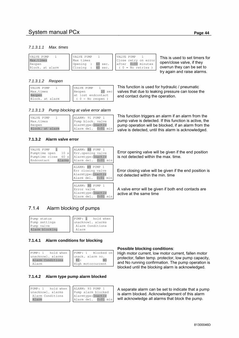
System manual PCx Page 44
81300046D
7.1.3.1.1 Max. times This is used to set timers for open/close valve, if they overrun they can be set to try again and raise alarms.
7.1.3.1.2 Reopen This function is used for hydraulic / pneumatic valves that due to leaking pressure can loose the end contact during the operation.
7.1.3.1.3 Pump blocking at valve error alarm This function triggers an alarm if an alarm from the pump valve is detected. If this function is active, the pump operation will be blocked, if an alarm from the valve is detected, until this alarm is acknowledged.
7.1.3.2 Alarm valve error
Error opening valve will be given if the end position is not detected within the max. time. Error closing valve will be given if the end position is not detected within the min. time A valve error will be given if both end contacts are active at the same time
7.1.4 Alarm blocking of pumps
7.1.4.1 Alarm conditions for blocking
Possible blocking conditions: High motor current, low motor current, fallen motor protector, fallen temp. protector, low pump capacity, and No running confirmation. The pump operation is blocked until the blocking alarm is acknowledged.
7.1.4.2 Alarm type pump alarm blocked
A separate alarm can be set to indicate that a pump is alarm blocked. Acknowledgement of this alarm will acknowledge all alarms that block the pump.
VALVE PUMP 1 Max.times Reopen Block. at alarm
VALVE PUMP 1 Max times Opening : 60 sec. Closing : 60 sec.
VALVE PUMP 1 Max.times Reopen Block. at alarm
VALVE PUMP 1 Reopen 10 sec at lost endcontact ( 0 = No reopen )
VALVE PUMP 1 Max.times Reopen Block. at alarm
ALARM: 91 PUMP 1 Pump block. valve Alarmtype:Inactiv Alarm del. 0:01 min
VALVE PUMP 1 Close retry on error after 0:00 minutes ( 0 = No retries )
Pump status Pump settings Pump valve Alarm blocking
PUMP: 1 hold when unacknowl. alarms Alarm Conditions Alarm
PUMP: 1 hold when unacknowl. alarms Alarm Conditions Alarm
PUMP: 1 Blocked on unack. alarm no. 81: NO High motorcurrent
PUMP: 1 hold when unacknowl. alarms Alarm Conditions Alarm
ALARM: 93 PUMP 1 Pump alarm blocked Alarmtype:Inactiv Alarm del. 0:01 min
VALVE PUMP 1 Pumptime open 10 s Pumptime close 60 s Endcontact Alarms
ALARM: 88 PUMP 1 Err.opening valve Alarmtype:Inactiv Alarm del. 0:01 min ALARM: 89 PUMP 1 Err closing valve Alarmtype:Inactiv Alarm del. 0:01 min ALARM: 90 PUMP 1 Error valve Alarmtype:Inactiv Alarm del. 0:01 min

System manual PCx Page 45
81300046D
7.2 Pumppit
Function key for program group ”PUMPPIT”
In certain cases this name is pump group instead of pump pit (for ex. pressure sensors in booster stations). The connection is the same as for ex. pump group 1 as for connection to the pump pit 1.
7.2.1 Status
In this menu are the status viewed for a pump pit. The status are for each pump pit: Pumped Volume and how many times and how long there have been two or more pumps running at the same time. The
status can be viewed 7 days back in time and the total amount.
7.2.1.1 Pumped volume
7.2.1.2 Multiple pumps running
Run times and number of occasions when 2 or more pumps have been running at the same time.
7.2.2 Settings
In the settings menu are the pump pits options and timers gathered.
7.2.2.1 Times
There are three timers that can be set for each pump pit, two for start and stop-delays and one run timer for alternating pumps.
7.2.2.1.1 Start-stop delays These timers are set to prevent simultaneous start or stop between pumps in automatic control mode. NOTE! The function that blocks the pumps is not affected by these times.
7 PUMP PIT
PUMPPIT: Status Settings Pumppit valve
PUMPPIT: Status Settings Pumppit valve
PUMPPIT: Status Pumped volume Multiple pumprun
PUMPPIT: 1 Status Pumped volume Multiple pumprun
Multi pump run PP:1 TOTAL Time: 0:00 h:mm Count: 0
Multi pump run PP:1 Today Time: 0:00 h:mm Count: 0
Multi pump run PP:1 Day 7 Time: 0:00 h:mm Count: 0
PUMPPIT: Status Settings Pumppit valve
PUMPPIT: 1 Timers Station flow Options
PUMPPIT: 1 Timers Station flow Options
PUMPPIT: 1 Timers: Start-stop delay Runtime alternator
PUMPPIT: 1 Timers: Mintime between Pumpstarts : 5 sec Pumpstop : 0 sec
PUMPPIT: 1 Timers: Start-stop delay Runtime alternator
PUMPPIT: Status Pumped volume Multiple pumprun
PUMPPIT: 1 TOTAL Pumped volume 15.0 m3
PUMPPIT: 1 Today Pumped volume 13.0 m3
PUMPPIT: 1 Day 7 Pumped volume 0.0 m3

System manual PCx Page 46
81300046D
7.2.2.1.2 Running time alternation Gives the possibility to alternate between pumps when running pumps. This alternate function is based on how long a pump has been running, instead of the alternation start function in the pump
menu. An alternation is made when the pump has been running continuously for a fixed time.
7.2.2.2 Station flow
In the menu for the station flow are all parameters for the flow in the pit entered.
7.2.2.2.1 Flow: Alarm set-points In the submenu Flow are the alarms for the inflow entered. A set point can be entered for High inflow and for Low inflow.
7.2.2.2.1.1 Alarm high inflow
7.2.2.2.1.2 Alarm low inflow
7.2.2.2.2 Pit area In the submenu pit area are the properties for the pit entered, see chapter 6.3.1.The shape can be rectangular or conical shape. Set new level and area for each level where the pit changes shape.
7.2.2.2.3 Pump flow compensation In the submenu Pump flow compensation can adjustments of the pump capacity can be set for the increased pressure when several pumps are running. Set a percentage of the pump capacity on each sets of pumps running, 2,3 up to 16 pumps.
PUMPPIT: 1 Timers: Start-stop delay Runtime alternator
PUMPPIT: 1 Timers: Runtime alternate after 0:00 hh:mm continuous running
PUMPPIT: 1 Timers Station flow Options
PUMPPIT: 1 Flow: Pit area Pump flow comp. Meas.parameters
PUMPPIT: 1 Flow: Pit area Pump flow comp. Meas.parameters
PUMPPIT: 1 Flow: High inflow alarm Low inflow alarm
PUMPPIT: 1 Flow: High inflow alarm Low inflow alarm
ALARM: 22 PUMPPIT 1 High inflow Alarmtype:Inactiv Alarm del. 0:01 min
ALARM: 22 PUMPPIT 1 High inflow Setpoint 0.0 l/s Hysteresis 0.0 l/s
PUMPPIT: 1 Flow: High inflow alarm Low inflow alarm
ALARM: 23 PUMPPIT 1 Low inflow Alarmtype:Inactiv Alarm del. 0:01 min
ALARM: 23 PUMPPIT 1 Low inflow Setpoint 0.0 l/s Hysteresis 0.0 l/s
PUMPPIT: 1 Flow: Pit area Pump flow comp. Meas.parameters
PUMPPIT: 1 Flow: Rect. pit shape Level 0 = 0.00 m Area 0 = 3.1 m2
PUMPPIT: 1 Flow: Pit area Pump flow comp. Meas.parameters
PUMPPIT: 1 Flow: Setting of pumpcapa- city when running 2 pumps = 85 %

System manual PCx Page 47
81300046D
PUMPPIT: 1 Options: High level float Overflow Level settings
7.2.2.2.4 Measuring parameters for flow calculation In the submenu Measuring parameters for flow calculation are the properties for the flow entered. If the pit is Emptying/filling a pit, measuring interval and properties of the pit for the calculation of the capacity of the pump
7.2.2.2.4.1 Emptying / Filling Controls if the measuring of the flow is in- or outgoing. In a normal sewage-pumping pit the pumps empty the pit, in a water tower the pumps fill the reservoir.
7.2.2.2.4.2 Measuring intervals The interval between calculations of the volume change in the pit. Longer time gives better accuracy at low flows and large pit areas.
7.2.2.2.4.3 Pump capacity – min. level / head of pumps See chapter 6.3.2. If the pit level drops below a pre-set value the calculation is stopped.
Head of pumps must be set if pump curves are used. Pump outlet should relate to the pit where pumps are placed.
7.2.2.3 Options
In the submenu Options are the alarmlevels for the pit entered also the overflow level and Backup control options.
7.2.2.3.1 High level float A high level float can be used for backup control and trigger an alarm.
7.2.2.3.1.1 Back-up start Gives the possibility to control pumps of free choice via a high level float if level sensor is damaged.
PUMPPIT: 1 Flow: Pit area Pump flow comp. Meas.parameters
PUMPPIT: 1 Flow: Emptying / Filling Meas. interval Pump Capacity
PUMPPIT: 1 Flow: Emptying / Filling Meas. interval Pump Capacity
PUMPPIT: 1 Flow: Pumps EMPTYING pit when pumping
PUMPPIT: 1 Flow: Emptying / Filling Meas. interval Pump Capacity
PUMPPIT: 1 Flow: Time between flow calculation = 10 sec ( 0 = OFF )
PUMPPIT: 1 Flow: Emptying / Filling Meas. interval Pump Capacity
PUMPPIT: 1 Flow: Option pumpcap.: Min lev. pumpcap. Head of pumps
PUMPPIT: 1 Flow: Option pumpcap.: Min lev. pumpcap. Head of pumps
PUMPPIT: 1 Flow: Min level in the pit for calc. of pump- capacity = 0.00 m
PUMPPIT: 1 Flow: Head of pumps for compensation with pumpcurve 0.00 m
PUMPPIT: 1 Timers Station flow Options
PUMPPIT: 1 Options: High level float Overflow Level settings
ALARM: 20 PUMPPIT 1 High float Alarmtype:A-Alarm Alarm del. 0:10 min
PUMPPIT: 1 Options: High level float Back-up start Alarm sensor Err.
PUMPPIT: 1 Options: High level float Back-up start Alarm sensor Err.
ALARM: 19 PUMPPIT 1 Hi float ctrl. Alarmtype:Inactiv Alarm del. 0:01 min
ALARM: 19 PUMPPIT 1 Hi float ctrl. Backup start: 0 sec Pump 1 Back-up OFF
PUMPPIT: 1 Flow: Pump outlet related to level in pumppit 1

System manual PCx Page 48
81300046D
7.2.2.3.1.2 Alarm sensor error The switch level for the high level float can be compared with the value from the level sensor. If not equal an error alarm can be set
7.2.2.3.2 Overflow The overflow alarm must be set active to be able to register an overflow. To avoid registering disturbances, in example
when waves occur, a delay of the alarm can be set. This delay will be active also when the level in the pit drops and the overflow stops. If no high level sensor is installed, can an overflow level be set. If an overflow sensor is installed this overflow level value is ignored.
7.2.2.3.3 Level settings In the Level settings, the alarms for low/high levels are entered and also the relative level of pit above the sea-level.
7.2.2.3.4 High level alarm
7.2.2.3.5 Low level alarm
7.2.2.3.6 Relative level , meters above sea level Here the reference level is set to show standardised levels.
7.2.3 Pumppit valve
The pumppit valve opens when any pump in the pit starts and closes when the last running pump shall stop. Otherwise the same function as pump valve.
PUMPPIT: Status Settings Pumppit valve
VALVE PUMPPIT 1 Pumptime open 10 s Pumptime close 60 s Endcontact Alarms
PUMPPIT: 1 Options: High level float Back-up start Alarm sensor Err.
ALARM: 25 PUMPPIT 1 Sensor error Alarmtype:Inactiv Alarm del. 0:01 min
PUMPPIT: 1 Options: High level float Alarm at 0.00 m Max deviation 0.00 m
PUMPPIT: 1 Options: High level float Overflow Level settings
ALARM: 21 PUMPPIT 1 Overflow Alarmtype:A-Alarm Alarm del. 0:10 min
PUMPPIT: 1 Options: Overfl.lev 0.000 m (If overflow float is not connected )
PUMPPIT: 1 Options: High level float Overflow Level settings
PUMPPIT: 1 Levels: High level alarm Low level alarm Relative level
PUMPPIT: 1 Levels: High level alarm Low level alarm Relative level
ALARM: 17 PUMPPIT 1 High level Alarmtype:B-Alarm Alarm del. 0:10 min
ALARM: 17 PUMPPIT 1 High level High level 5.00 m Hysteresis 0.05 m
PUMPPIT: 1 Levels: High level alarm Low level alarm Relative level
ALARM: 18 PUMPPIT 1 Low level Alarmtype:Inactiv Alarm del. 0:01 min
ALARM: 18 PUMPPIT 1 Low level Low level 0.50 m Hysteresis 0.05 m
PUMPPIT: 1 Levels: High level alarm Low level alarm Relative level
PUMPPIT: 1 Levels: Relative level at sensor 0-point 0.00 m

System manual PCx Page 49
81300046D
7.2.3.1 End contacts
7.2.3.1.1 Max. times
7.2.3.1.2 Reopen This function is used for hydraulic / pneumatic valves that can loose the end contact due to loss of pressure during operation.
7.2.3.1.3 Pump blocking at alarm If this alarm is active the pump is blocked until the alarm for the error end contact is acknowledged.
7.2.3.2 Alarm valve error
Opening error is shown if end contact is not detected within max. time Closing error is shown if end contact is not detected within max. time. Valve error is given if both end contacts are active together
VALVE PUMPPIT 1 Pumptime open 10 s Pumptime close 60 s Endcontact Alarms
VALVE PUMPPIT 1 Max.times Reopen Block. at alarm
VALVE PUMPPIT 1 Max times Opening : 60 sec. Closing : 60 sec.
VALVE PUMPPIT 1 Max.times Reopen Block. at alarm
VALVE PUMPPIT 1 Reopen 10 sec at lost endcontact ( 0 = No reopen )
VALVE PUMPPIT 1 Max.times Reopen Block. at alarm
ALARM: 30 PUMPPIT 1 Pump block. valve Alarmtype:Inactiv Alarm del. 0:01 min
VALVE PUMPPIT 1 Close retry on error after 0:00 minutes ( 0 = No retries )
VALVE PUMPPIT 1 Max.times Reopen Block. at alarm
VALVE PUMPPIT 1 Pumptime open 10 s Pumptime close 60 s Endcontact Alarms
ALARM: 27 PUMPPIT 1 Error opening valve Alarmtype:Inactiv Alarm del. 0:01 min ALARM: 28 PUMPPIT 1 Error closing valve Alarmtype:Inactiv Alarm del. 0:01 min ALARM: 29 PUMPPIT 1 Valve error Alarmtype:Inactiv Alarm del. 0:01 min

System manual PCx Page 50
81300046D
7.3 Alarm Show /Program
Function key for program group ”ALARM”
The alarm menu is split into 3 sub menus:
Status In this submenu the alarms are acknowledged and selected. Settings In this submenu there are different possibilities to set alarm types and alarm delays for all alarms. Set-point values for the different alarms are however set in the actual program group(for ex. high level in pumppit is set in menu group pumppit). For every digital in- and outputs separate alarm can be set independently of the IO function. Many IO functions have except from this alarm own alarms that are automatically coupled. An input for ex. fallen motor protector can therefore have 2 alarms if alarm motor protector is set under pump key and further alarm for the digital input if the input is activated to trigger an alarm. Therefore the independent IO alarms should only be used where the input is not connected to a IO function which has equivalent alarm, which can generate two alarms instead of only one Set alarms This submenu gives an overview over the used alarms. In this menu only set alarms can be changed.
7.3.1 Status
In the status menu the alarms are acknowledged and the status of the alarms are viewed.
7.3.1.1 Selection alarm status
In this menu is there a choice for filtering the list depending on alarm types. This menu is also available via the ”ENTER” key when showing alarms in the other status menus.
The selection criteria for all alarm types is (A, B, or. C alarm) and is the default setting when entering the status menu.
7.3.1.2 Not acknowledged alarms
In the list of Not acknowledged alarms are alarms viewed by stepping with the arrow keys. Pressing the RESET ALARM/ FUNCTION key when the alarm is showing in the panel does acknowledgement of an alarm. The actual time for the acknowledgement is shown. Next alarm is shown by pressing the arrow keys. This message is shown, when all alarms are acknowledged.
9 ALARM
ALARM: Status Configure Set alarms
VIEW CRITERIA Not ackn.alarms Active alarms All alarms
ALARM: Status Configure Set alarms
VIEW CRITERIA Not ackn.alarms Active alarms All alarms
BALARM 100 PUMP 2 Fallen tempprot. On 990201 11.50:45 ALARM ACTIVE
RESET ALARM
FUNCTION
BALARM 100 PUMP 2 Fallen tempprot. Ack. Local 990205 14.56:12
VIEW CRITERIA Not ackn.alarms NO NON ACKNOWLEDGED A, B, or C Alarm
VIEW CRITERIA Not ackn.alarms Active alarms All alarms
VIEW CRITERIA = A, B, or C Alarm (Change, press Enter when in alarm list)

System manual PCx Page 51
81300046D
7.3.1.3 Active alarms
Under active alarms both acknowledged and unacknowledged alarms are shown. The key RESET ALARMS / FUNCTION” acknowledges or shows when acknowledgement was done.
7.3.1.4 All alarms
Under All alarms is the whole alarm list shown. Shows which time an alarm has gone active, inactive and when the acknowledgement was done.
7.3.2 Settings
Under the settings menu can new alarms be set. There are two ways to view the alarms either in their alarm group or number. An access code for alarm acknowledgement can be set.
7.3.2.1 Alarms in groups
The alarms are split into 6 main groups Last in this manual are all alarms listed.
7.3.2.1.1 System The system alarms have numbers 1-9 and are as follows. Person alarm Ext. Person alarm UC in local mode Modem error Telephone error Configuration error (Given for a part of the most common errors in setting)
7.3.2.1.2 Pump pit The pumppit alarms have alarm no. 17-80 for pumppit 1 to 4. Following alarms for each pumppit. High level Low level Back-up start High float Overflow High inflow Low inflow Sensor error Pumps DI blocked Error open valve Error close valve Valve error Pumps blocked by valve error
VIEW CRITERIA Not ackn.alarms Active alarms All alarms
BALARM 100 PUMP 2 Fallen tempprot. On 990201 11.50:45 ALARM ACTIVE
VIEW CRITERIA Not ackn.alarms Active alarms All alarms
BALARM 100 PUMP 2 Fallen tempprot. On 990201 11.50:45 Off 990205 15.00:14
SETTINGS: Alarms: In groups Alarms:Number order Ackn. access
ALARM: Status Configure Set alarms
SETTINGS: Alarms: In groups Alarms:Number order Ackn. access
ALARM GROUPS: System Pumppit 1 Pump 1 Flow/Pulse com. IO module
System manual PCx Page 52
81300046D
7.3.2.1.3 Pump The pump alarms have alarm no. 81-336 for pump 1 to 16. Following alarms available for each pump. High motor current Low motor current Fallen motor protector Fallen temp. protector Low pump capacity No running confirmation Pump blocked Error open valve Error close valve Valve error Pump blocked by valve error Error motor protector Pump alarm blocked
7.3.2.1.4 Flow/Pulse High alarms for flows have alarm no. 337-352 Alarm number 337-340 for overflow 1-4, Alarm number 341-344 for flow meter 1-4, Alarm number 345-352 for pulse channels 1-8.
7.3.2.1.5 Communication Alarms that can occur when the PCx is acting as a Comli/Modbus master, is always communication error for the master channel (slave does not answer), and error when calling for each master channel.
7.3.2.1.6 IO-module The alarm group IO module is split into 5 sub groups for IO signals and power supply.
7.3.2.1.6.1 General Following general alarms are available for each IO module. Power failure (Alarm when module switches over to battery back-up) Low voltage (Voltage level is below the set alarm level for a IO-module F116) IO module missing (Cable or hardware error) AI-board missing (hardware error) Sensor error (Alarm for that a mA signal is below 3 mA for 4-20 mA signals)
7.3.2.1.6.2 Digital inputs(D.in) Each digital input (1-16) can generate an alarm when the input goes active. NOTE! Possibility for double alarms as described in chapter 6.3 settings.
7.3.2.1.6.3 Analogue inputs(A.in) High and low alarms can be activated for each analogue input (1-4). Note that for ex. the level alarm for pumppit has separate alarm numbers for high and low level alarm. NOTE! Possibility for double alarms as described in chapter 6.3 settings.
ALARM GROUPS: System Pumppit 1 Pump 1 Flow/Pulse com. IO module
ALARM IO MODUL 1 General D.in A.in D.out A.out

System manual PCx Page 53
81300046D
7.3.2.1.6.4 Digital outputs (D.out) Each digital output(1-8) can generate an alarm when the output goes active.
7.3.2.1.6.5 Analogue outputs (A.out) High and low level alarm can be set for each analogue output.
7.3.2.2 Alarm number order
Includes all alarms. Input an alarm number or step with the arrow keys. See alarm list page 131.
7.3.2.3 Access for alarm acknowledgement
This function can be used to set an Access level to acknowledge alarms, where only authorised personnel is allowed to acknowledge alarms, also personal access codes can be set.
This is selected if Operator/system access level is needed to acknoledge alarms.
With a personal code it will be known who reseted an alarm through that code. Up to 9 diffrent codes can be set.
7.3.3 Set alarms
This menu filters all alarms that have been set and gives a good overview of all alarms that are in use and the possibility to change alarm type and delay.
SETTINGS: Alarms: In groups Alarms:Number order Ackn. access
ALARM: 1 SYSTEM Person alarm Alarmtype:A-Alarm Alarm del. 3:00 min
SETTINGS: Alarms: In groups Alarms:Number order Ackn. access
ACCESS FOR ALARM- ACKNOWLEDGEMENT: No restrictions ACCESS FOR ALARM- ACKNOWLEDGEMENT: Operator Code ACCESS FOR ALARM- ACKNOWLEDGEMENT: Personal Code
Alarm Acknowl.code Person 1 Code: Name: 1234 = Charlie
ALARM: Status Configure Set alarms
ALARM: 1 SYSTEM Person alarm Alarmtype:A-Alarm Alarm del. 3:00 min
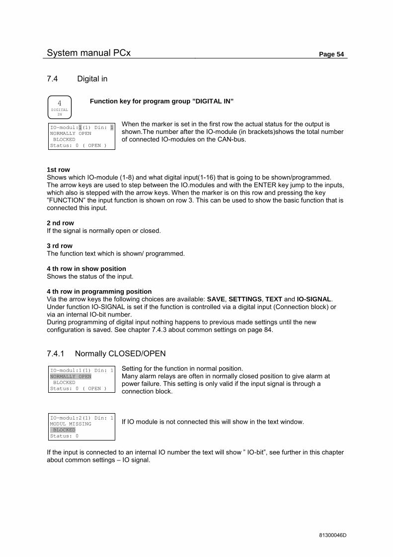
System manual PCx Page 54
81300046D
7.4 Digital in
Function key for program group ”DIGITAL IN”
When the marker is set in the first row the actual status for the output is shown.The number after the IO-module (in brackets)shows the total number of connected IO-modules on the CAN-bus.
1st row Shows which IO-module (1-8) and what digital input(1-16) that is going to be shown/programmed. The arrow keys are used to step between the IO.modules and with the ENTER key jump to the inputs, which also is stepped with the arrow keys. When the marker is on this row and pressing the key ”FUNCTION” the input function is shown on row 3. This can be used to show the basic function that is connected this input. 2 nd row If the signal is normally open or closed. 3 rd row The function text which is shown/ programmed. 4 th row in show position Shows the status of the input. 4 th row in programming position Via the arrow keys the following choices are available: SAVE, SETTINGS, TEXT and IO-SIGNAL. Under function IO-SIGNAL is set if the function is controlled via a digital input (Connection block) or via an internal IO-bit number. During programming of digital input nothing happens to previous made settings until the new configuration is saved. See chapter 7.4.3 about common settings on page 84.
7.4.1 Normally CLOSED/OPEN
Setting for the function in normal position. Many alarm relays are often in normally closed position to give alarm at power failure. This setting is only valid if the input signal is through a connection block.
If IO module is not connected this will show in the text window.
If the input is connected to an internal IO number the text will show ” IO-bit”, see further in this chapter about common settings – IO signal.
4 DIGITAL
IN
IO-modul:1(1) Din: 1 NORMALLY OPEN BLOCKED Status: 0 ( OPEN )
IO-modul:1(1) Din: 1 NORMALLY OPEN BLOCKED Status: 0 ( OPEN )
IO-modul:2(1) Din: 1 MODUL MISSING BLOCKED Status: 0

System manual PCx Page 55
81300046D
7.4.2 Input types
Following input types are available Type no. Function Connected to 0 Closed 1 High level float pumppit Pumppit 1-4 2 Overflow pumppit Pumppit 1-4 3 Start confirmation pump Pump 1-16 4 Motor protector pump Pump 1-16 5 Temp. protector pump Pump 1-16 6 Block pumps Pump 1-16 7 Block pumppit Pumppit 1-4 8 End position valve open Pump 1-16 and Pumppit 1-4 9 End position valve closed Pump 1-16 and Pumppit 1-4 10 Pulse input (Rain, Flow, Energy) Pulse channel 1-8 11 Alarm inputs of free choice. 12 Person alarm (Visiting alarm and local display) 13 Ext. Person alarm. 14 Start float. Pump 1-16 and Pumppit 1-4 15 Stop float. Pump 1-16 and Pumppit 1-4 16 Block PID controller PID regulator 1-2 17 Block output Output of free choice(IO-no 0-63) 18 Activate output Output of free choice(IO-no 0-63) 19 Shift motor Max (End position) Shift motor 1-4 20 Shift motor Min (End position) Shift motor 1-4 21 Block Shift motor Shift motor 1-4 22 Force Shift motor Shift motor 1-4 23 Block pump start Pump 1-16 and Pumppit 1-4 24 Block derivata control Pumppit 1-4 25 Power failure IO-module IO-module 1-8 26 Alarm Acknowledge 27 Manual start of pump Pump 1-16
7.4.2.1 Closed
Output unused.
7.4.2.2 High level float pumppit
Set a pumppit no. to which the float belongs. Other relevant settings are made in program group ”PUMPPIT”.
7.4.2.3 Overflow pumppit
Set a pumppit no. to which the overflow sensor belongs. Other relevant settings are made in program group ”PUMPPIT”.
IO-modul:1(1) Din: 1 NORMALLY OPEN BLOCKED SAVE
IO-modul:1(1) Din: 1 NORMALLY OPEN HIGHFLOAT PUMPPIT PUMPPIT: 1
IO-modul:1(1) Din: 1 NORMALLY OPEN OVERFLOW PP: PUMPPIT: 1
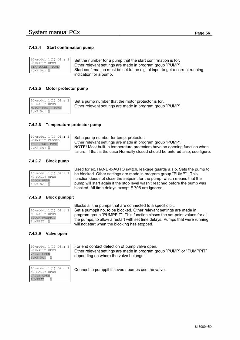
System manual PCx Page 56
81300046D
7.4.2.4 Start confirmation pump
Set the number for a pump that the start confirmation is for. Other relevant settings are made in program group ”PUMP”. Start confirmation must be set to the digital input to get a correct running indication for a pump.
7.4.2.5 Motor protector pump
Set a pump number that the motor protector is for. Other relevant settings are made in program group ”PUMP”.
7.4.2.6 Temperature protector pump
Set a pump number for temp. protector. Other relevant settings are made in program group ”PUMP”. NOTE! Most built-in temperature protectors have an opening function when failure. If that is the case Normally closed should be entered also, see figure.
7.4.2.7 Block pump
Used for ex. HAND-0-AUTO switch, leakage guards a.s.o. Sets the pump to be blocked. Other settings are made in program group ”PUMP”. This function does not close the setpoint for the pump, which means that the pump will start again if the stop level wasn’t reached before the pump was blocked. All time delays except F.705 are ignored.
7.4.2.8 Block pumppit
Blocks all the pumps that are connected to a specific pit. Set a pumppit no. to be blocked. Other relevant settings are made in program group ”PUMPPIT”. This function closes the set-point values for all the pumps, to allow a restart with set time delays. Pumps that were running will not start when the blocking has stopped.
7.4.2.9 Valve open
For end contact detection of pump valve open. Other relevant settings are made in program group ”PUMP” or “PUMPPIT” depending on where the valve belongs. Connect to pumppit if several pumps use the valve.
IO-modul:1(1) Din: 1 NORMALLY OPEN STARTCONF. PUMP PUMP No: 1
IO-modul:1(1) Din: 1 NORMALLY OPEN MOTOR PROT. PUMP PUMP No: 1
IO-modul:1(1) Din: 1 NORMALLY CLOSED TEMP.PROT PUMP PUMP No: 1
IO-modul:1(1) Din: 1 NORMALLY OPEN BLOCK PUMP PUMP No: 1
IO-modul:1(1) Din: 1 NORMALLY OPEN BLOCK PUMPPIT PUMPPIT: 1
IO-modul:1(1) Din: 1 NORMALLY OPEN VALVE OPEN PUMP No. 1
IO-modul:1(1) Din: 1 NORMALLY OPEN VALVE OPEN PUMPPIT 1

System manual PCx Page 57
81300046D
7.4.2.10 Valve closed
For end contact detection of pump valve is closed. Other relevant settings are made in program group ”PUMP” or “PUMPPIT” depending on where the valve belongs. Connect to pumppit if several pumps use valve
7.4.2.11 Pulse input
The maximum amount of pulse inputs is 8 in the system. The Max pulse freq. is 100 Hz with Min pulse time of 5 mSec. Enter a pulse channel 1-8.
Following flow types can be selected: Flow (l/s), Flow (m3/h), Energy (kW), Rain (l/s*ha), Own type (unit./s), Own type (unit/h)
For user typed unit a menu of own units is added. Scaling can be a volume units/pulse or a pulses/volume unit
7.4.2.12 Alarm input
An alarm input uses the general IO alarms for digital inputs.
7.4.2.13 Person alarm
The alarm number 1 is the person alarm and is connected through a DI. The person alarm is normally connected to a light switch in a station. When the input is activated, a timer starts that generates a person alarm when it is overrun. The timer is set to zero every time a key on the PCx is pressed also each time the light switch is turned on.
To the person alarm a digital output can be connected that will signal when the timer needs to be reseted. The local mode can be selected for one or all communication ports. This means that all remote control is blocked from these ports (All Comli/Modbus writing to PCx is blocked in local mode). A LED in the front of the PCx shows local mode. Personal alarm is always transmitted even if all other alarm calls are blocked when visiting. Alarm type and times for the person alarm are set in program group “ ALARM “.
IO-modul:1(1) Din: 1 NORMALLY OPEN VALVE CLOSED PUMP No. 1
IO-modul:1(1) Din: 1 NORMALLY OPEN VALVE CLOSED PUMPPIT 1
IO-modul:1(1) Din: 1 NORMALLY OPEN PULSE INPUT PULSE CHANNEL:1(1-8)
IO-modul:1(1) Din: 1 NORMALLY OPEN PULSE INPUT 1 SETTINGS
IO-modul:1(1) Din: 1 Flow (l/s) PULSE INPUT 1 1 pulse = 0.000 l
IO-modul:1(1) Din: 1 Flow (l/s) PULSE INPUT 1 1 l = 0.0 pulses
IO-modul:1(1) Din: 1 User type (units/s) Pulse unit l Flow unit l/s
IO-modul:1(1) Din: 1 NORMALLY OPEN ALARM INPUT ALARM
ALARM:385 DIN 1:1 ALARM INPUT Alarmtype:Inactiv Alarm del. 0:01 min
IO-modul:1(1) Din: 1 NORMALLY OPEN PERSON ALARM Local mode? NO
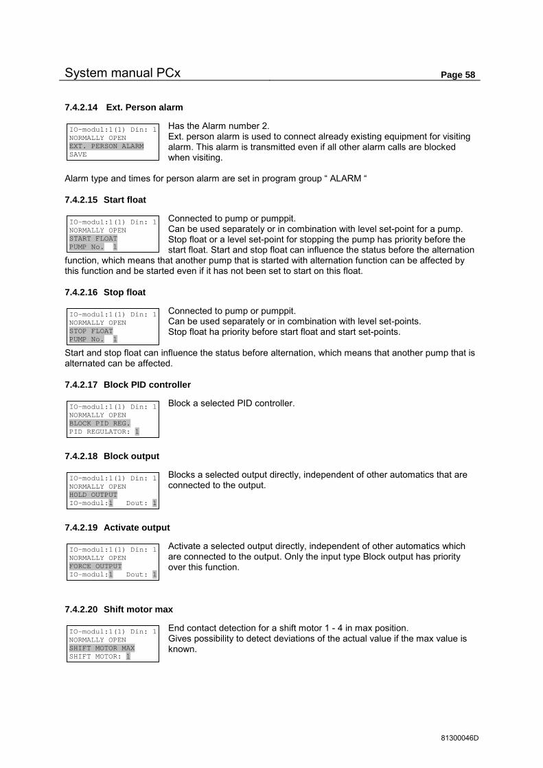
System manual PCx Page 58
81300046D
7.4.2.14 Ext. Person alarm
Has the Alarm number 2. Ext. person alarm is used to connect already existing equipment for visiting alarm. This alarm is transmitted even if all other alarm calls are blocked when visiting.
Alarm type and times for person alarm are set in program group “ ALARM “
7.4.2.15 Start float
Connected to pump or pumppit. Can be used separately or in combination with level set-point for a pump. Stop float or a level set-point for stopping the pump has priority before the start float. Start and stop float can influence the status before the alternation
function, which means that another pump that is started with alternation function can be affected by this function and be started even if it has not been set to start on this float.
7.4.2.16 Stop float
Connected to pump or pumppit. Can be used separately or in combination with level set-points. Stop float ha priority before start float and start set-points.
Start and stop float can influence the status before alternation, which means that another pump that is alternated can be affected.
7.4.2.17 Block PID controller
Block a selected PID controller.
7.4.2.18 Block output
Blocks a selected output directly, independent of other automatics that are connected to the output.
7.4.2.19 Activate output
Activate a selected output directly, independent of other automatics which are connected to the output. Only the input type Block output has priority over this function.
7.4.2.20 Shift motor max
End contact detection for a shift motor 1 - 4 in max position. Gives possibility to detect deviations of the actual value if the max value is known.
IO-modul:1(1) Din: 1 NORMALLY OPEN EXT. PERSON ALARM SAVE
IO-modul:1(1) Din: 1 NORMALLY OPEN START FLOAT PUMP No. 1
IO-modul:1(1) Din: 1 NORMALLY OPEN STOP FLOAT PUMP No. 1
IO-modul:1(1) Din: 1 NORMALLY OPEN BLOCK PID REG. PID REGULATOR: 1
IO-modul:1(1) Din: 1 NORMALLY OPEN HOLD OUTPUT IO-modul:1 Dout: 1
IO-modul:1(1) Din: 1 NORMALLY OPEN FORCE OUTPUT IO-modul:1 Dout: 1
IO-modul:1(1) Din: 1 NORMALLY OPEN SHIFT MOTOR MAX SHIFT MOTOR: 1

System manual PCx Page 59
81300046D
7.4.2.21 Shift motor min
End contact detection for shift motor 1 - 4 min position Gives possibility to detect deviations of the actual value if the min value is known.
7.4.2.22 Block shift motor
Used for HAND-0-AUTO switch for shift motors
7.4.2.23 Force shift motor
Forces the shift motor to a preset setpoint in F.720
7.4.2.24 Block pump start
Connect to pump or pumppit. Blocks the start command to pumps in off position. Pumps that are running are not affected.
7.4.2.25 Block derivata control
Blocks derivata control of pumps (see F.708). Choose pump pit.
Select partial or full blocking.
7.4.2.26 Power failure IO-module
Sets an alarm when a electric power loss happens for a specific IO-module
IO-modul:1(1) Din: 1 NORMALLY OPEN SHIFT MOTOR MIN SHIFT MOTOR: 1
IO-modul:1(1) Din: 1 NORMALLY OPEN HOLD SHIFT MOTOR SHIFT MOTOR: 1
IO-modul:1(1) Din: 1 NORMALLY OPEN BLOCK P. START PUMP No. 1
IO-modul:1(1) Din: 1 NORMALLY OPEN FORCE SHIFT MOTOR SHIFT MOTOR: 1
IO-modul:1(1) Din: 1 NORMALLY OPEN BLOCK. DERIVATA PP PUMPPIT: 1 IO-modul:1(1) Din: 1 NORMALLY OPEN BLOCK. DERIVATA PP 1 SETTINGS
IO-modul:1(1) Din: 1 Block level derivata control (F.708) for Start and stop
IO-modul:1(1) Din: 1 Block level derivata control (F.708) for Start only IO-modul:1(1) Din: 1 Block level derivata control (F.708) for Stop only
IO-modul:1(1) Din: 1 NORMALLY OPEN POWER FAIL IO-MOD. IO-modul:1

System manual PCx Page 60
81300046D
7.4.2.27 Alarm acknowledge
To acknowledge alarms on an extern button. All alarms will be acknowledged.
7.4.2.28 Manual start of pump
Will start a pump on an input. The pump will stop if a stop level is reached. If the level is below the stop setpoint, the pump will only be run when the input is active
IO-modul:1(1) Din: 1 NORMALLY OPEN AALLAARRMM AACCKKNN.. SAVE
IO-modul:1(1) Din: 1 NORMALLY OPEN MANUAL START PUMP PUMP NO. 1

System manual PCx Page 61
81300046D
7.4.3 Common settings for digital inputs
On row 4 there are the alternatives SAVE, SETTINGS, TEXT, IO-SIGNAL, and in some cases ALARM. These can be selected by pressing the arrow keys and then enter
7.4.3.1 Save
If there are no further settings to be made for the input, save is shown on the last row. If settings have been changed a question is shown which must be confirmed with YES and <ENTER> for the new settings to be accepted. The question ”SAVE CHANGES” is shown if the CANCEL key is used to go backwards after changes have been made.
7.4.3.2 Settings
If further settings are available for the input SETTINGS is shown for these input types.
7.4.3.3 Own text for inputs
Own user text can be used for all types of inputs. The standard text is shown again when the input type is changed. If the text have been changed the real function behind the own typed text is shown
when the “FUNCTION” key is be pressed, for ex. The own text is “ ERROR FAN” and when the funcion key is pressed it will show “ ALARM INPUT”.
7.4.3.4 IO-signal
Input signals can be connected to internal I/O numbers instead of normal terminals, to allow more complex function in the PCx.. When IO number is selected the input is totally independent of the input terminal. It is recommended to use IO-bit primarily on not connected IO-modules INV. IO-bit inverts status from selected IO number, meaning IO status 0 gives DI status 1 and vice versa. In the main menu the digital inputs are indicated as IO-bit or INV. IO-bit on row 2.
The choice normally open / closed is not available for IO-bit.
IO-modul:1(1) Din: 1 NORMALLY OPEN ALARM INPUT TEXT
IO-modul:1(1) Din: 1 NORMALLY OPEN PULSE INPUT 1 SETTINGS
IO-modul:1(1) Din: 1 Flow (l/s) PULSE INPUT 1 1 l = 0.0 pulses
IO-modul:1(1) Din: 1 NORMALLY OPEN MY OWN ALARM TEXT TEXT
IO-modul:1(1) Din: 1 NORMALLY OPEN ALARM INPUT IO-SIGNAL
IO-modul:1(1) Din: 1 NORMALLY OPEN ALARM INPUT LOCAL IO (Terminal) IO-modul:1(1) Din: 1 NORMALLY OPEN ALARM INPUT IO-bit: 0
IO-modul:5(1) Din: 1 IO-BIT ALARM INPUT Status: 0
IO-modul:1(1) Din: 1 NORMALLY OPEN ALARM INPUT INV. IO-bit: 0

System manual PCx Page 62
81300046D
7.5 Digital out
Function key for program group ”DIGITAL OUT”
If the marker is on row 1 the actual status for the output is shown. The number after the IO-module (In brackets) shows the number of connected IO-modules. IO-modul 1 is PCx and 2-8 is PCxp with the CAN ID 2-8
1 st row The seleceted IO-module (1-8) and Digital output (1-8) that is to be shown/programmed. The arrow keys are used to step between the modules and with enter key jump to the outputs, which also are stepped with the arrow keys. If the marker is on row 1 and the ”FUNCTION” key is pressed the function type will be shown on row 3. 2 nd row If the output is normally open or closed. 3 rd row Shows/ programmes the function of the output or a free programmable text that describes the function. 4 th row in show position her the status of the input is shown. 4:e row in programming mode Via the arrow keys following selections are available: SAVE, SETTINGS, and TEXT. During programming of a digital output the earlier settings are not influenced until the new settings are saved.
7.5.1 Normally CLOSED/OPEN
Setting for normal position. An alarm output is often normally closed to register an alarm when the power failures. If IO module is not connected this text is shown.
5 DIGITAL OUT
IO-modul:1(1)Dout: 1 NORMALLY OPEN BLOCKED Status: 0 ( OPEN )
IO-modul:1(1)Dout: 1 NORMALLY OPEN BLOCKED Status: 0 ( OPEN )
IO-modul:2(1)Dout: 1 MODUL MISSING BLOCKED Status: 0 ( OPEN )

System manual PCx Page 63
81300046D
7.5.2 Output types
Following output types are available Type no. Function Connected to 0 Closed 1 Pump Pump 1-16 2 Valve control Pump 1-16 and Pumppit 1-4 3 Open valve Pump 1-16 and Pumppit 1-4 4 Close valve Pump 1-16 and Pumppit 1-4 5 Start confirmation pumppit Pumppit 1-4 6 Not acknowledged alarm A,B,C alarm 7 Selective alarm outputs 1-6 alarm numbers of free choice 8 remote controlled output 9 Signal person alarm 10 Alarm active A,B,C alarm 11 Alarm pulse (at new alarm) A,B,C alarm 12 Reset motor protector Pump 1-16 and Pumppit 1-4 13 Reverse pump Pump 1-16 14 Spray pit Pump 1-16 and Pumppit 1-4 15 IO-bit. IO no 0-4095 16 Logic IO 1-5 IO no. Of free choice 17 Pre-set volume flow meter Overflow 1-4, and flow meter 1-4 18 Pre-set number of pulses Pulse channel 1-8 19 Pre-set pit flow Pumppit 1-4 20 Timer Free floating or timer 1-9. 21 Setpoint Analogue value of free choice. 22 Variable speed controlled pump Pump 1-16 23 Shift motor increase Shift motor 1-4 24 Shift motor decrease Shift motor 1-4 25 Compare register data 2 data registers of free choice 26 Setpoint window Analogue value of free choice. 27 Modem power COM 1-2
7.5.2.1 Closed
When not an output is used.
7.5.2.2 Pump
Sets the output to control a pump. Options are 1-16. Other settings for the pump are in program group ”PUMP”
7.5.2.3 Valve control
For pump valves with a single control mechanism. The output is active when the valve is open and inactive when closed. Connected to PUMP or PUMPPIT Other settings in program group ”PUMP” or ”PUMPPIT”
IO-modul:1(1)Dout: 1 NORMALLY OPEN BLOCKED SAVE
IO-modul:1(1)Dout: 1 NORMALLY OPEN PUMP PUMP No: 1
IO-modul:1(1)Dout: 1 NORMALLY OPEN VALVE CONTR. PUMP No. 1
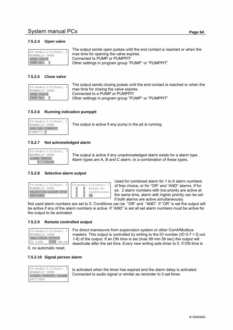
System manual PCx Page 64
81300046D
7.5.2.4 Open valve
The output sends open pulses until the end contact is reached or when the max time for opening the valve expires. Connected to PUMP or PUMPPIT Other settings in program group ”PUMP” or ”PUMPPIT”
7.5.2.5 Close valve
The output sends closing pulses until the end contact is reached or when the max time for closing the valve expires. Connected to a PUMP or PUMPPIT Other settings in program group ”PUMP” or ”PUMPPIT”
7.5.2.6 Running indication pumppit
The output is active if any pump in the pit is running.
7.5.2.7 Not acknowledged alarm
The output is active if any unacknowledged alarm exists for a alarm type. Alarm types are A, B and C alarm, or a combination of these types.
7.5.2.8 Selective alarm output
Used for combined alarm for 1 to 6 alarm numbers of free choice, or for “OR” and “AND” alarms. If for ex. 2 alarm numbers with low priority are active at the same time, alarm with higher priority can be set if both alarms are active simultaneously.
Not used alarm numbers are set to 0. Conditions can be ”OR” and ”AND”. If ”OR” is set the output will be active if any of the alarm numbers is active. If ”AND” is set all set alarm numbers must be active for the output to be activated.
7.5.2.9 Remote controlled output
For direct manoeuvre from supervision system or other Comli/Modbus masters. This output is controlled by writing to the IO number (IO 0-7 = D.out 1-8) of the output. If an ON time is set (max 99 min 59 sec) the output will deactivate after the set time. Every new writing sets timer to 0. If ON time is
0, no automatic reset.
7.5.2.10 Signal person alarm
Is activated when the timer has expired and the alarm delay is activated. Connected to audio signal or similar as reminder to 0 set timer.
IO-modul:1(1)Dout: 1 NORMALLY OPEN OPEN VALVE PUMP No. 1
IO-modul:1(1)Dout: 1 NORMALLY OPEN RUN.IND PUMPPIT PUMPPIT:1
IO-modul:1(1)Dout: 1 0 0 Alarm no. 0 0 conditions: 0 0 OR
IO-modul:1(1)Dout: 1 NORMALLY OPEN ALARM UNACK. A - Alarm
IO-modul:1(1)Dout: 1 NORMALLY OPEN SELECTIVE ALARM OUTP SETTINGS
IO-modul:1(1)Dout: 1 NORMALLY OPEN SIGNAL PERSON. ALARM SETTINGS
IO-modul:1(1)Dout: 1 NORMALLY OPEN OPEN VALVE PUMP No. 1
IO-modul:1(1)Dout: 1 NORMALLY OPEN REM.CONTR OUTPUT On time 0:00 mm:ss

System manual PCx Page 65
81300046D
7.5.2.11 Alarm active
This output is active if alarms are active for selected alarm types. Alarm types are A, B and C alarm, or a combination of these types.
7.5.2.12 Alarm pulse
Gives a pulse every time a new alarm occurs for selected alarm type(s). Alarm types are A, B and C alarm, or a combination of these types. Pulse time from 1 sec. to 99 min 59 sec Used for existing alarm calling systems.
7.5.2.13 Reset motor protector
For autoresetting a motor protector. If resetting is done for all protectors at the same time, PUMPPIT is set instead of PUMP NO. The reset sequence starts in this case if any of the motor protectors in the pumppit is set.
The delay time must be long enough for the protector to cool down before resetting. Pulse time tells how long the output shall be active when resetting the protector. When max number of retries is exceeded the resetting is stopped and an alarm ”Error motor protector ” is given. The condition for a successful reset attempt is when the running time of the pump exceeds the set Delay time. When the alarm for Error motor protector is restored is the counter for retries set to 0.
7.5.2.14 Reverse pump
For automatic or remote reversing of pump. The conditions for automatic control of the reversing are set in program group ”PUMP”.
Delay time is the shortest time the pump must be stopped before a reversing sequence starts if the pump is running. Reverse time is how long time the output should be active. Pump relay is set to OFF if the manoeuvre of the pump is made from the reversing contact. If the reversing contact only changes the phase sequence the Pump relay is set to ON for pump manoeuvre via the normal pump output.
7.5.2.15 Spray
For automatic cleaning of pumppit after pre-set no. of stops or starts of pumps. The number can be on starts and stops in the PUMPPIT or on separate PUMP NO. Select if the pre-set number shall be on pump STOP
or START. This controls if spraying shall start at low STOP level or at high START level. Up to 99 starts/stops between sprayings can be set. Spraying time can be up to 99 min and 59 sec.
IO-modul:1(1)Dout: 1 NORMALLY OPEN ALARM ACTIVE A - Alarm
IO-modul:1(1)Dout: 1 NORMALLY OPEN ALARM PULSE A - Alarm
IO-modul:1(1)Dout: 1 NORMALLY OPEN A ALARM PULSE On time 0:00 mm:ss
IO-modul:1(1)Dout: 1 NORMALLY OPEN RESET M-PROT. PUMP No. 1
IO-modul:1(1)Dout: 1 Delay 30 sec Pulse time 1 sec No of retries 1
IO-modul:1(1)Dout: 1 NORMALLY OPEN REVERSE PUMP PUMP No: 1
IO-modul:1(1)Dout: 1 Delay 5 sec Reverse time 1 sec Pump relay OFF
IO-modul:1(1)Dout: 1 NORMALLY OPEN SPRAY PUMP No. 1
IO-modul:1(1)Dout: 1 NORMALLY OPEN 10 STOP betw. spray On time 1:00 mm:ss

System manual PCx Page 66
81300046D
7.5.2.16 IO-bit
Used to connect a IO number free of choice to an output either as a pulse when the IO goes active, or with start and stop delay. When the IO number is the actual function for the IO number, it is shown on row 2 and 3. The IO-number can be changed with the arrow keys.
ON DELAY can be set up to 999:59 mm:ss. If the selected IO number is inactive before the time delay is OFF no contact function will be given. Pulse time or Off delay is set according to wanted function, max 999:59 mm:ss. Contact function will be given with set pulse time even if the IO-number goes inactive earlier. Alarm blocking can be set to OFF or ON and gives possibility to block the output if it has been active longer time than set alarm delay. To release the blocking, the alarm for the output has to be acknowledged.
7.5.2.17 Logic IO
For logic conditions on 1 to 5 IO numbers free of choice. Following conditions can be set: ”OR ON”, ”AND ON”, ”OR OFF”, ”AND OFF”. To see help texts for the function of the IO numbers the FUNCTION key can be pressed when the marker is on the field for the IO-number. Can be changed with arrow keys.
SELECT IO number for signal 1-5, and NORMAL (1=True) or INVERTED (0=True) for the signal. For not used signals the IO number should be set to –1 to indicate this.
7.5.2.18 Pre-set value flow meters
Give a pulse when pre-set volume is reached. Used for external counters and control of samplers.
Select wanted flow signal, flow 1-4=Overflow for Pumppit1-4, flow 5-8=Flow meter 1-4. Pulse time from 0.5 – 99 sec. Pre-set flow volume from 0.1 – 6553.5 m3 / pulse.
7.5.2.19 Pre-set pulse volume
Gives a pulse when pre-set volume is reached. Used for external counters and control of samplers. Select wanted flow signal, pulse channel 1-8. Pulse time from 0.5 – 99 sec.
Pre-set flow volume from 0.1 – 6553.5 pulse units / pulse.
IO-modul:1(1)Dout: 1 NORMALLY OPEN IO-BIT SETTINGS
IO-modul:1(1)Dout: 1 D.OUT 1:2 PUMP 2 IO-bit: 1
IO-modul:1(1)Dout: 1 On delay 0:00 m:s Pulse time 0:00 m:s Alarm hold: OFF
ALARM:417 DOUT 1:1 IO-BIT Alarmtype:Inactiv Alarm del. 0:01 min
IO-modul:1(1)Dout: 1 NORMALLY OPEN IO-BIT SETTINGS
IO-modul:1(1)Dout: 1 NORMALLY OPEN LOGIC IO SETTINGS
IO-modul:1(1)Dout: 1 Condition OR IO-ON Signal 1 IO 1 NORMAL IO-modul:1(1)Dout: 1 DOUT 1:2 PUMP 2 IO-number: 1
IO-modul:1(1)Dout: 1 NORMALLY OPEN FLOW PULSE FL.M. Flow:1 Ov.flow 1
IO-modul:1(1)Dout: 1 NORMALLY OPEN On time 1 sec 0.0 m3 / pulse
IO-modul:1(1)Dout: 1 NORMALLY OPEN FLOW PULSE P.CH. Flow:1 Pulsch. 1
IO-modul:1(1)Dout: 1 NORMALLY OPEN On time 1 sec 0.0 l / pulse
IO-modul:1(1)Dout: 1 On delay 0:00 m:s Off delay 0:00 m:s Alarm hold: OFF

System manual PCx Page 67
81300046D
7.5.2.20 Pre-set pit flow
Gives a pulse when pre-set volume is reached Used for external counters and control of samplers
Select the wanted flow signal, pumppit 1-4. Pulse time from 0.5 – 99 sec. Pre-set flow volume from. 0.1 – 6553.5 m3 / pulse
7.5.2.21 Timer
Timer can be free running or connected to a set value in F.110. Max pause or pulse time is 999 min. 59 sec. Timer 1-8 controls normal time - night time The output can indicate actual time with delay up to 999:59 mm:ss. Alternatively a pulse can be generated at specific time. Pulse Night time, Normal time or Night +Normal time can be set.
Off (pause) time sets On delay up to 999:59 mm:ss On (pulse) time set the time for contact closure max 999:59 mm:ss
Timer 9 is a week timer with separate settings for each day. With this timer the output follows the actual status.
7.5.2.22 Setpoint
The setpoint value can be coupled to any analogue input choice. On and Off set-point are set separately On delay can be set up to 99:59 mm:ss
7.5.2.23 Variable speed controlled pump
All pumps, which are to be speed controlled with the built-in speed control logic in the PCx, must have this output type.
If “control with this contact” is set to ”YES” the normal contact is always Off when the pump is speed controlled. If ”NO” is set the contact is used to connect the pump to the frequency converter and the manoeuvre of the pump is done via the normal pump contact. See chap. 6.5 page.27. In program group ”PUMP” the pump must be VARIABLE SPEED if this output type should work.
7.5.2.24 Shift motor increase
Contact output for control of shift motors. Select shift motor 1 – 4. All other settings made in F.720.
IO-modul:1(1)Dout: 1 NORMALLY OPEN TIMER Free running
IO-modul:1(1)Dout: 1 NORMALLY OPEN Off time 0:01 m:s On time 0:01 m:s
IO-modul:1(1)Dout: 1 NORMALLY OPEN TIMER Day timer 1 (PP1)
IO-modul:1(1)Dout: 1 Status Night time Night del. 0:01 m:s Day delay 0:01 m:s IO-modul:1(1)Dout: 1 Pulse Night time Off time 0:01 m:s On time 0:01 m:s
IO-modul:1(1)Dout: 1 NORMALLY OPEN TIMER Week timer 9
IO-modul:1(1)Dout: 1 NORMALLY OPEN SETPOINT SETTINGS
IO-modul:1(1)Dout: 1 NORMALLY OPEN IO-mod 1 AIN 1 Levelsensor PP 1
IO-modul:1(1)Dout: 1 NORMALLY OPEN SETPOINT SETTINGS
IO-modul:1(1)Dout: 1 On 1.00 m Off 2.00 m On delay 0:00 m:s
IO-modul:1(1)Dout: 1 NORMALLY OPEN VAR.SPEED PUMP PUMP No: 1
IO-modul:1(1)Dout: 1 NORMALLY OPEN On-Off control with this contact? NO
IO-modul:1(1)Dout: 1 NORMALLY OPEN SHIFT MOTOR INC. SHIFT MOTOR: 1
IO-modul:1(1)Dout: 1 NORMALLY OPEN FLOW PULSE P.CH. Flow:1 Pulsch. 1
IO-modul:1(1)Dout: 1 NORMALLY OPEN On time 1 sec 0.0 l / pulse

System manual PCx Page 68
81300046D
7.5.2.25 Shift motor decrease
Contact output for control of shift motors Select shift motor 1 – 4. All other settings made in F.720.
7.5.2.26 Compare register data
Compares content in 2 Data registers. If conditions are fulfilled the output goes active. Possible conditions are ”<”, ”<=”, ”=”, ”>=”and ”>”. The register numbers can be 0 – 65535.
See separate Comli/Modbus register manual for description of data register. At double registers the higher register number is set . For comparison with own set-points F.808 can be used for writing to free Data registers.
7.5.2.27 Setpoint window
The setpoint window can be coupled to any analogue input.
Output is active when signal is between Max and Min setting. If Max is set lower than Min, the output function is inverted (output active for signals outside window).
On delay can be set up to 99:59 mm:ss
7.5.2.28 Modem Power
Power to modem on either COM1 or COM2. The PCx has a built in function that can reset a modem that has been jammed or working correctly.
7.5.3 Common setting for digital outputs
On row 4 are alternatives for SETTINGS, SAVE and TEXT. These can be selected via arrow keys.
7.5.3.1 Settings
Shows other settings for selected type. If no further settings this picture is shown.
7.5.3.2 Save
When the settings are ready SAVE will show on the lowest row. If settings have been changed the SAVE CHANGES show and must be confirmed with YES and <ENTER> before the new values are valid. The question ”SAVE CHANGES” even show if you
try to go backward with the CANCEL key after changes have been made.
IO-modul:1(1)Dout: 1 NORMALLY OPEN SHIFT MOTOR DEC. SHIFT MOTOR: 1
IO-modul:1(1)Dout: 1 NORMALLY OPEN COMPARE REGISTERDATA SETTINGS
IO-modul:1(1)Dout: 1 NORMALLY OPEN COMPARE REGISTERDATA R. 1 < R. 2
IO-modul:1(1)Dout: 1 NORMALLY OPEN BLOCKED SAVE
IO-modul:1(1)Dout: 1 NORMALLY OPEN BLOCKED SAVE CHANGES YES
IO-modul:1(1)Dout: 1 NORMALLY OPEN BLOCKED SETTINGS
IO-modul:1(1)Dout: 1 No further config possible in this menu
IO-modul:1(1)Dout: 1 NORMALLY OPEN SETPOINT WINDOW SETTINGS
IO-modul:1(1)Dout: 1 NORMALLY OPEN IO-mod 1 AIN 1 Levelsensor PP 1
IO-modul:1(1)Dout: 1 NORMALLY OPEN SETPOINT WINDOW SETTINGS
IO-modul:1(1)Dout: 1 Max 2.00 m Min 1.00 m On delay 0:00 m:s
IO-modul:1(1)Dout: 1 NORMALLY OPEN MODEM POWER COM: 1

System manual PCx Page 69
81300046D
7.5.3.3 Own text for outputs
Own text can be used for all types of outputs. The standard text reappears when the output type is changed. To check the function behind own text, the
”FUNCTION” key can be pressed when the marker is on row 1.
IO-modul:1(1)Dout: 1 NORMALLY OPEN PUMP 1 TEXT
IO-modul:1(1)Dout: 1 NORMALLY OPEN Booster pump 1 TEXT

System manual PCx Page 70
81300046D
7.6 Analogue in
Function key for program group ”ANALOGUE IN”
When the marker is on the first row the actual status for the input is shown. The number behind the IO-module (in brackets) shows number of connected IO-modules. IO-module 1 is PCx and 2-8 is PCxp with the CAN ID 2-8
1st row Here is shown which IO-module (1-8) and what analogue input(1-46) is going to be shown/programmed. The arrow keys are used to step between the inputs. When the marker is on this row, pressing the key ”FUNCTION” can show the input function on row 3. This is used to show the basic function that is behind own texts. 2nd row shows which board type (type of input signal) at connected to the input.. For inputs with missing analogue input board the text below is shown.
If the input is connected to an internal Data register the following is shown. See chapter about common settings – IO signal.
3rd row Here is shown /programmed which signal type or. Free text that describes the desired function. 4 th row in show position Shows the status of the input. 4 th row in programming position Through the arrow keys are the following choices available: SAVE, SETTINGS, TEXT and IO-SIGNAL. Under function IO-SIGNAL is set if the function is controlled via an analogue input board (Connection block) or via an internal data register number. During programming of analogue input nothing happens to previous made settings until the new configuration is saved.
1 ANALOGUE
IN
IO-module:2(1) Ain:1 No input Blocked Value: 0
IO-module:2(1) Ain:1 Data register Blocked Value: 0
IO-module:1(1) Ain:1 mA input Levelsensor PP 1 Value: 4.02 m
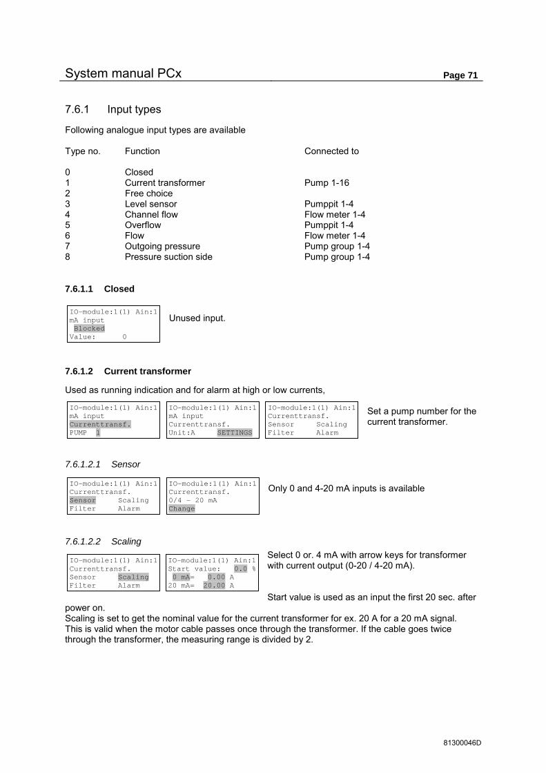
System manual PCx Page 71
81300046D
7.6.1 Input types
Following analogue input types are available Type no. Function Connected to 0 Closed 1 Current transformer Pump 1-16 2 Free choice 3 Level sensor Pumppit 1-4 4 Channel flow Flow meter 1-4 5 Overflow Pumppit 1-4 6 Flow Flow meter 1-4 7 Outgoing pressure Pump group 1-4 8 Pressure suction side Pump group 1-4
7.6.1.1 Closed
Unused input.
7.6.1.2 Current transformer
Used as running indication and for alarm at high or low currents, Set a pump number for the current transformer.
7.6.1.2.1 Sensor Only 0 and 4-20 mA inputs is available
7.6.1.2.2 Scaling Select 0 or. 4 mA with arrow keys for transformer with current output (0-20 / 4-20 mA). Start value is used as an input the first 20 sec. after
power on. Scaling is set to get the nominal value for the current transformer for ex. 20 A for a 20 mA signal. This is valid when the motor cable passes once through the transformer. If the cable goes twice through the transformer, the measuring range is divided by 2.
IO-module:1(1) Ain:1 mA input Blocked Value: 0
IO-module:1(1) Ain:1 mA input Currenttransf. PUMP 1
IO-module:1(1) Ain:1 mA input Currenttransf. Unit:A SETTINGS
IO-module:1(1) Ain:1 Currenttransf. Sensor Scaling Filter Alarm
IO-module:1(1) Ain:1 Currenttransf. Sensor Scaling Filter Alarm
IO-module:1(1) Ain:1 Currenttransf. 0/4 - 20 mA Change
IO-module:1(1) Ain:1 Currenttransf. Sensor Scaling Filter Alarm
IO-module:1(1) Ain:1 Start value: 0.0 % 0 mA= 0.00 A 20 mA= 20.00 A

System manual PCx Page 72
81300046D
7.6.1.3 Free choice
Used for external measuring value where logging , alarms and set-points are needed. Set a wanted unit and no. of decimals for display. See common settings about free text.
7.6.1.3.1 Sensor For free type of signal with normal mA signal from an external sensor.
7.6.1.3.2 Scaling Select 0 or. 4 mA with arrow keys (0-20 / 4-20 mA). Scaling is normally set to the nominal measuring range for the sensor. Start value is used as input the first 20 sec. after the power up.
7.6.1.4 Level sensor
Used for level sensor, which is connected to pumppit with associated control functions. Set to pumppit to control or general for level indication only. Unit can be in meter or cm.
7.6.1.4.1 Sensor The level sensor is often a 4-20 mA signal.
7.6.1.4.2 Scaling Chose 0 or 4 mA with arrow keys (0-20 / 4-20 mA). Scaling is normally set to the nominal measuring range for the sensor. Start value is used as input the first 20 sec. after power on.
7.6.1.5 Channel flow
Connection of level sensor for flow metering in open channels and weirs Select flow meter 1-4 As Channel flow is based on in a channel or weir the unit can be set as meter or mm.
IO-module:1(1) Ain:1 mA input Free-choice Unit:unit 2 decim.
IO-module:1(1) Ain:1 mA input Free-choice Unit:unit SETTINGS
IO-module:1(1) Ain:1 Free-choice Sensor Scaling Filter Alarm
IO-module:1(1) Ain:1 Free-choice Sensor Scaling Filter Alarm
IO-module:1(1) Ain:1 Free-choice 0/4 - 20 mA Change
IO-module:1(1) Ain:1 Free-choice Sensor Scaling Filter Alarm
IO-module:1(1) Ain:1 Start value: 0.0 % 4 mA= 0.00 unit 20 mA= 10.00 unit
IO-module:1(1) Ain:1 mA input Levelsensor PUMPPIT 1
IO-module:1(1) Ain:1 mA input Levelsensor PP 1 Unit:m SETTINGS
IO-module:1(1) Ain:1 Levelsensor PP 1 Sensor Scaling Filter Alarm
IO-module:1(1) Ain:1 Levelsensor PP 1 Sensor Scaling Filter Alarm
IO-module:1(1) Ain:1 Levelsensor PP 1 0/4 - 20 mA Change
IO-module:1(1) Ain:1 Levelsensor PP 1 Sensor Scaling Filter Alarm
IO-module:1(1) Ain:1 Start value: 0.0 % 4 mA= 0.00 m 20 mA= 10.00 m
IO-module:1(1) Ain:1 mA input Channel flow Flowmeter no.1
IO-module:1(1) Ain:1 mA input Channel flow 1 Unit:m SETTINGS
IO-module:1(1) Ain:1 Channel flow 1 Sensor Scaling Filter Alarm

System manual PCx Page 73
81300046D
7.6.1.5.1 Sensor The level sensor is mostly a 2 wire submersible sensor.
7.6.1.5.2 Scaling Start value is used as input the first 20 sec. after power on. Chose 0 or 4 mA with arrow keys (0-20 / 4-20 mA). Scaling is normally set to the nominal measuring range for the sensor. If the 0 point of the sensor is the weir edge, the 0 point is adjusted so
that 0.000 m is exactly at the weir edge. Is the sensor mounted for ex. 0.1 m below the edge the scaling must be adjusted for this. Note! The difference between 0/4 mA and 20 mA must be the total measuring span of the sensor.
7.6.1.6 Overflow
The overflow can be measured with a separate level sensor, if the overflow is in such a way that the normal sensor can’t be used. If overflow switch is connected the measurement starts when the switch goes active or a set overflow level is reached if overflow switch isn’t connected. See overflow page 48.
Chose pumppit 1-4 and a level unit, in meter or mm.
7.6.1.6.1 Sensor Level sensor is often a 2 wire submersible sensor.
7.6.1.6.2 Scaling Chose 0 or 4 mA with arrow keys(0-20 / 4-20 mA). Scaling is normally set to the nominal measuring range for the sensor. See also chapter 7.2.2.3.2. Start value is used in the first 20 sec. after power on.
7.6.1.7 Flow
For external flow sensors where accumulation, logging, alarm limits and set-point are needed. Select flow meter 1-4.
These are the same as for channel flow, which means that external flow sensors must have an own number. Unit can be in l/s or m3/h.
IO-module:1(1) Ain:1 Channel flow 1 Sensor Scaling Filter Alarm
IO-module:1(1) Ain:1 Channel flow 1 0/4 - 20 mA Sensor OK
IO-module:1(1) Ain:1 Channel flow 1 Sensor Scaling Filter Alarm
IO-module:1(1) Ain:1 Start value: 0.0 % 4 mA= 0.000 m 20 mA= 1.000 m
IO-module:1(1) Ain:1 mA input Flow Flowmeter no.1
IO-module:1(1) Ain:1 mA input Flow 1 Unit:l/s SETTINGS
IO-module:1(1) Ain:1 Flow 1 Sensor Scaling Filter Alarm
IO-module:1(1) Ain:1 mA input Overflow PUMPPIT 1
IO-module:1(1) Ain:1 mA input Overflow Unit:m SETTINGS
IO-module:1(1) Ain:1 Overflow Sensor Scaling Filter Alarm
IO-module:1(1) Ain:1 Overflow Sensor Scaling Filter Alarm
IO-module:1(1) Ain:1 Overflow 0/4 - 20 mA Sensor OK
IO-module:1(1) Ain:1 Overflow Sensor Scaling Filter Alarm
IO-module:1(1) Ain:1 Start value: 0.0 % 4 mA= 0.000 m 20 mA= 1.000 m

System manual PCx Page 74
81300046D
7.6.1.7.1 Sensors Sensor is most times a 0/4-20 mA signal from an external Flow sensor.
7.6.1.7.2 Scaling Chose 0 or 4 mA with arrow keys(0-20 / 4-20 mA).. Scaling is normally set to the nominal measuring range for the sensor. Start value is used as input the first 20 sec. after power on.
7.6.1.8 Outgoing pressure
Used for booster stations where the pressure sensor is connected to the pumppit associated control functions.
Chose general or pump group 1-4. Connecting to pump group is the same as connection to pumppit.
7.6.1.8.1 Sensor Sensor is normally a 0/4-20 mA signal from external pressure sensor.
7.6.1.8.2 Scaling Scaling is normally set to the nominal measuring range for the sensor.. Start value is used as input the first 20 sec. after power on.
7.6.1.9 Pressure suction side
This type is used for speed controlled pumps to limit the outgoing pressure if suction pressure is low. Chose general or Pump group 1-4. Connection to pump group is the same as connection to pumppit.
7.6.1.9.1 Sensor Sensor is normally a 0/4-20 mA signal from external pressure sensor.
IO-module:1(1) Ain:1 Flow 1 Sensor Scaling Filter Alarm
IO-module:1(1) Ain:1 Flow 1 0/4 - 20 mA Sensor OK
IO-module:1(1) Ain:1 Flow 1 Sensor Scaling Filter Alarm
IO-module:1(1) Ain:1 Start value: 0.0 % 4 mA= 0.00 l/s 20 mA= 10.00 l/s
IO-module:1(1) Ain:1 mA input Pressure out PUMPGROUP 1
IO-module:1(1) Ain:1 mA input Pressure out PG.1 Unit:bar SETTINGS
IO-module:1(1) Ain:1 Pressure out PG.1 Sensor Scaling Filter Alarm
IO-module:1(1) Ain:1 Pressure out PG.1 Sensor Scaling Filter Alarm
IO-module:1(1) Ain:1 Pressure out PG.1 0/4 - 20 mA Sensor OK
IO-module:1(1) Ain:1 Pressure out PG.1 Sensor Scaling Filter Alarm
IO-module:1(1) Ain:1 Start value: 80.0 % 4 mA= 0.00 bar 20 mA= 10.00 bar
IO-module:1(1) Ain:1 mA input Pressure in PUMPGROUP 1
IO-module:1(1) Ain:1 mA input Pressure in PG.1 Unit:bar SETTINGS
IO-module:1(1) Ain:1 Pressure in PG.1 Sensor Scaling Filter Alarm
IO-module:1(1) Ain:1 Pressure in PG.1 Sensor Scaling Filter Alarm
IO-module:1(1) Ain:1 Pressure in PG.1 0/4 - 20 mA Sensor OK
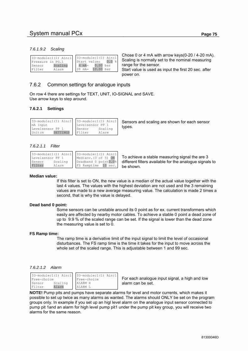
System manual PCx Page 75
81300046D
7.6.1.9.2 Scaling Chose 0 or 4 mA with arrow keys(0-20 / 4-20 mA). Scaling is normally set to the nominal measuring range for the sensor. Start value is used as input the first 20 sec. after power on.
7.6.2 Common settings for analogue inputs
On row 4 there are settings for TEXT, UNIT, IO-SIGNAL and SAVE. Use arrow keys to step around.
7.6.2.1 Settings
Sensors and scaling are shown for each sensor types.
7.6.2.1.1 Filter To achieve a stable measuring signal the are 3 different filters available for the analogue signals to be shown.
Median value:
If this filter is set to ON, the new value is a median of the actual value together with the last 4 values. The values with the highest deviation are not used and the 3 remaining values are made to a new average measuring value. The calculation is made 2 times a second, that is why the value is delayed.
Dead band 0 point:
Some sensors can be unstable around its 0 point as for ex. current transformers which easily are affected by nearby motor cables. To achieve a stable 0 point a dead zone of up to 9.9 % of the scaled range can be set. If the signal is lower than the dead zone the measuring value is set to 0.
FS Ramp time:
The ramp time is a derivative limit of the input signal to limit the level of occasional disturbances. The FS ramp time is the time it takes for the input to move across the whole set of the scaled range. This is adjustable between 1 and 99 sec.
7.6.2.1.2 Alarm For each analogue input signal, a high and low alarm can be set.
NOTE! Pump pits and pumps have separate alarms for level and motor currents, which makes it possible to set up twice as many alarms as wanted. The alarms should ONLY be set on the program groups only. In example if you set up an higl level alarm on the analogue input sensor connected to pump pit 1and an alarm for high level pump pit1 under the pump pit key group, you will receive two alarms for the same reason.
IO-module:1(1) Ain:1 Pressure in PG.1 Sensor Scaling Filter Alarm
IO-module:1(1) Ain:1 Start value: 0.0 % 4 mA= 0.00 bar 20 mA= 10.00 bar
IO-module:1(1) Ain:1 mA input Levelsensor PP 1 Unit:m SETTINGS
IO-module:1(1) Ain:1 Levelsensor PP 1 Sensor Scaling Filter Alarm
IO-module:1(1) Ain:1 Levelsensor PP 1 Sensor Scaling Filter Alarm
IO-module:1(1) Ain:1 Medianv.(3 of 5) ON Deadband 0 point0.0% FS Ramptime 10 sec.
IO-module:1(1) Ain:1 Free-choice Sensor Scaling Filter Alarm
IO-module:1(1) Ain:1 Free-choice ALARM H ALARM L

System manual PCx Page 76
81300046D
7.6.2.1.2.1 High alarm
7.6.2.1.2.2 Low alarm
7.6.2.2 Own texts on inputs
Own texts can be set for all types of inputs. The standard text will show when the input type is changed. To check to function behind own text the FUNCTION key can be pressed when the marker is on row 1.
7.6.2.3 Own unit on inputs
The unit can be changed for every input. Input types with forward connection should use preset units, for ex. level sensor for channel flow can not have decimetres as unit. The decimals in the display should normally be set to 3-4 digits accuracy for
scaled range.
7.6.2.4 IO-signal
The input signal can be selected from a Data register number or as a differential signal of 2 other inputs. Standard setting is a local signal from an input board.
If Data reg. is set the signal is not connected to the physical input. Therefore use this function primarily for inputs on IO-modules that are not connected to the system. Can be used for ex. Com. signals.
Even at differential measurement the signal is not connected to the physical input. Use this function primarily on not connected IO-modules
Differential measurement can for ex. be used for grid control. A new differential signal is made from the 2 set inputs. The difference is calculated from the scaled value, which the 2 input signals can have different measuring ranges.
Even at addition the signal is not connected to the physical input. Use this function primarily on not connected IO-modules. Addition can for example be used for the summation of 2 flows
IO-module:1(1) Ain:1 mA input Free-choice Unit:unit TEXT
IO-module:1(1) Ain:1 mA input My weight Unit:unit
IO-module:1(1) Ain:1 Free-choice ALARM H ALARM L
ALARM:401 HA AIN 1:1 Free-choice Alarmtype:Inactiv Alarm del. 0:01 min
IO-module:1(1) Ain:1 Free-choice Alarm H. 10.00 unit Hysteres. 0.10 unit
IO-module:1(1) Ain:1 Free-choice ALARM H ALARM L
ALARM:402 LA AIN 1:1 Free-choice Alarmtype:Inactiv Alarm del. 0:01 min
IO-module:1(1) Ain:1 Free-choice Alarm L. 0.00 unit Hysteres. 0.05 unit
IO-module:1(1) Ain:1 mA input My weight Unit:unit UNIT
IO-module:1(1) Ain:1 mA input My weight Unit:Kg 1 decim.
IO-module:1(1) Ain:1 mA input Free-choice Unit:unit IO-SIGNAL
IO-module:1(1) Ain:1 mA input Free-choice LOCAL IO (Terminal)
IO-module:1(1) Ain:1 mA input Free-choice Data-reg. 0
IO-module:1(1) Ain:1 mA input Free-choice DIFFERENC Ain1:2-1:3
IO-module:1(1) Ain:1 mA input Free-choice ADDITION Ain1:2+1:3

System manual PCx Page 77
81300046D
7.6.2.4.1 Scaling data The register values are set for wanted measuring range.
7.6.2.4.2 Scaling differential measurement and addition Wanted measuring range is set in engineer units. This measuring range is used for reading integer data (0-65535) with Comli/Modbus.
7.6.2.5 Save
When setting is done, SAVE can be selected. If changes have been made they must be confirmed with YES and <ENTER> to activate the changes. Question for ”SAVE CHANGES” will appear even with the CANCEL key if any changes have been
made.
IO-module:1(1) Ain:1 Difference Free-choice Unit:m SAVE
IO-module:1(1) Ain:1 Difference Free-choice SAVE CHANGES YES
IO-module:1(1) Ain:1 Free-choice DATA Reg Scaling Filter Alarm
IO-module:1(1) Ain:1 Free-choice 0= 0.00 m 65535= 10.00 m
IO-module:1(1) Ain:1 Free-choice DIFF. Scaling Filter Alarm
IO-module:1(1) Ain:1 Free-choice 0% = 0.00 m 100% = 10.00 m

System manual PCx Page 78
81300046D
7.7 Analogue out
Functions key for program group ”ANALOGUE OUT”
When the marker is on row 1 the actual output signal is shown. The number behind the IO-module( in brackets ) shows the number of IO-modules connected. The IO-module 1 is the PCx and 2-8 is PCxp with the CAN ID 2-8
1st row Here is set which I/O module (1-8) and Analogue output (1-2) is to be shown/programmed. 2nd row Shows which signal is connected to the output. 3rd row Shows the actual value of the mA signal 4th row Through the arrow keys are the following choices available: SCALING, SAVE and ALARM.
7.7.1 Signal choice
Following signals are available for connection to the output signal. Signal Index area Level pumppit 1-4 Inflow pumppit 1-4 Outflow pumppit 1-4 Overflow pumppit 1-4 Flow meter 1-4 Overflow level pumppit 1-4 Level flow meter 1-4 Pulse channel 1-8 IO-module 1 Analogue in 1-4 Analogue input signal according to actual settings IO-module 2 Analogue in 1-4 IO-module 3 Analogue in 1-4 IO-module 4 Analogue in 1-4 IO-module 5 Analogue in 1-4 IO-module 6 Analogue in 1-4 IO-module 7 Analogue in 1-4 IO-module 8 Analogue in 1-4 Data register 0-12287 PID controller 1-2 Speed PID 1-2 Pressure 1-4 Suction pressure 1-4 Volume pumppit 1-4
Wanted signal is selected via the arrow keys
2 ANALOGU
E OUT
IO-modul:1(1) Aout:1 Outsignal: 6.464 mA Scale
IO-modul:1(1) Aout:1 LEVEL PP. 1
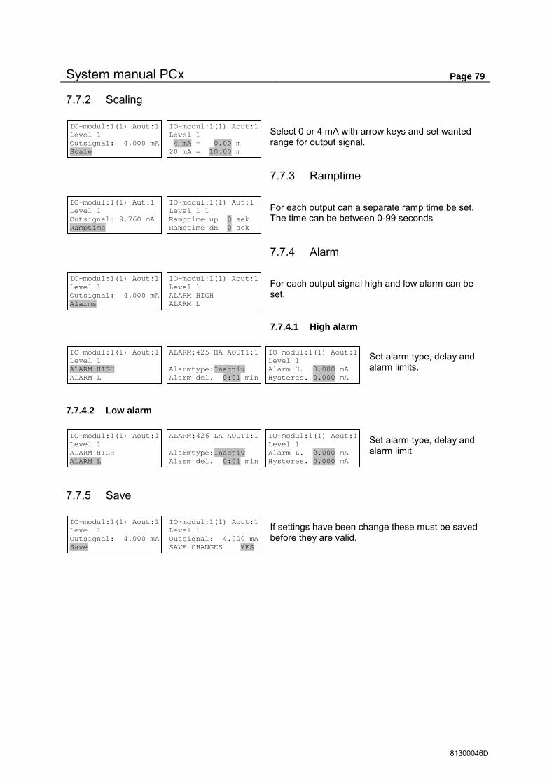
System manual PCx Page 79
81300046D
7.7.2 Scaling
Select 0 or 4 mA with arrow keys and set wanted range for output signal.
7.7.3 Ramptime
For each output can a separate ramp time be set. The time can be between 0-99 seconds
7.7.4 Alarm
For each output signal high and low alarm can be set.
7.7.4.1 High alarm
Set alarm type, delay and alarm limits.
7.7.4.2 Low alarm
Set alarm type, delay and alarm limit
7.7.5 Save
If settings have been change these must be saved before they are valid.
IO-modul:1(1) Aout:1 Level 1 Outsignal: 4.000 mA Scale
IO-modul:1(1) Aout:1 Level 1 4 mA = 0.00 m 20 mA = 10.00 m
IO-modul:1(1) Aout:1 Level 1 Outsignal: 4.000 mA Alarms
IO-modul:1(1) Aout:1 Level 1 ALARM HIGH ALARM L
IO-modul:1(1) Aout:1 Level 1 ALARM HIGH ALARM L
ALARM:425 HA AOUT1:1 Alarmtype:Inactiv Alarm del. 0:01 min
IO-modul:1(1) Aout:1 Level 1 Alarm H. 0.000 mA Hysteres. 0.000 mA
IO-modul:1(1) Aout:1 Level 1 ALARM HIGH ALARM L
ALARM:426 LA AOUT1:1 Alarmtype:Inactiv Alarm del. 0:01 min
IO-modul:1(1) Aout:1 Level 1 Alarm L. 0.000 mA Hysteres. 0.000 mA
IO-modul:1(1) Aout:1 Level 1 Outsignal: 4.000 mA Save
IO-modul:1(1) Aout:1 Level 1 Outsignal: 4.000 mA SAVE CHANGES YES
IO-modul:1(1) Aut:1 Level 1 Outsignal: 9.760 mA Ramptime
IO-modul:1(1) Aut:1 Level 1 1 Ramptime up 0 sek Ramptime dn 0 sek

System manual PCx Page 80
81300046D
7.8 Flow/pulse
Function key for program group ”FLOW/PULSE”
In this program group all data for flow meters and pulse volumes are shown. Here the weir and channel types for open channel flow meters are set.
All accumulated values are available as total accumulated and as totals for 7 days + today value. Today’s value is updated to midnight and is than mowed to yesterday and 0- set.
The different values are selected via the arrow keys on the marked fields.
7.8.1 Accumulated volume
Accumulated volume is split into 3 sub groups. A:IN flow shows the overflow value for pumppit 1-4 And analogue flow meter 1-4. D:IN pulse flow shows the accumulated values for pulse channels 1-8. Actual set text for the digital inputs is used as name. Pumped volume is selected for pumppit 1-4.
7.8.2 Overflow status
The overflow status shows the overflow time and number of overflows in pump pit 1-4
Accumulated flow Ovfl. status Actual values Channel flow config
3 FLOW/ PULSE
Accumulated flow Ovfl. status Actual values Channel flow config
Accumulated flow: A:IN flow D:IN Pulse flow Pumped flow
Accumulated flow: A:IN flow D:IN Pulse flow Pumped flow
1 Ov.flow 1 TOTAL Accumulated flow 0.0 m3
PUMPPIT: 1 Today Pumped volume 0.0 m3
PUMPPIT: 1 Day 1 Pumped volume 0.0 m3
PUMPPIT: 1 Day 2 Pumped volume 0.0 m3
PUMPPIT: 1 Day 3 Pumped volume 0.0 m3
PUMPPIT: 1 Day 4 Pumped volume 0.0 m3
PUMPPIT: 1 Day 5 Pumped volume 0.0 m3
PUMPPIT: 1 Day 6 Pumped volume 0.0 m3
PUMPPIT: 1 Day 7 Pumped volume 0.0 m3
Accumulated flow: A:IN flow D:IN Pulse flow Pumped flow
1 ENERGY TOTAL Accumulated flow 89034.3 kWh
Accumulated flow: A:IN flow D:IN Pulse flow Pumped flow
PUMPPIT: 1 TOTAL Pumped volume 0.0 m3
Accumulated flow Ovfl. status Actual values Channel flow config
PP 1 Overflow status TOTAL Ovfl.time 0:00 h No.: 0
PUMPPIT: 1 TOTAL Pumped volume 0.0 m3

System manual PCx Page 81
81300046D
7.8.3 Actual values
The actual values show the actual analogue measuring values and are split into 2 sub groups. Flow meter shows actual flow + measuring level for open channel flow meters or external flow meters. Pulse times for pulse channel 1-8 are recalculated to actual intensity values to show actual flows. ”Fluctuating ” values can occur when the pulse times are very long.
7.8.4 Configuration channel flow
For channel flow certain rules must be considered for lay out and mounting, see flow information on page 17
configuration of weir type for channel flow can be set for overflow pumppit 1-4 and flow meter 1-4. When entering the actual weir type is shown
7.8.4.1 Weir type
Not used flow meters are set to Closed.
7.8.4.1.1 Straight weir without and with contraction For straight weir without contraction the weir width and weir height shall be set. See page 17
With side contraction even the channel width shall be set.
7.8.4.1.2 Thompson (V-weir)
For V-notch (Thompson) weir the angle must be set. See page 18.
Accumulated flow Ovfl. status Actual values Channel flow config
Actual values: Flow meters Pulse channels
Actual values: Flow meters Pulse channels
1 Ov.flow 1 Meas.lev.: 0.000 m Flow: 0.000 l/s = 0.000 m3/h
Actual values: Flow meters Pulse channels
1 Energy 15.0 kW Digital inp. 12
Accumulated flow Ovfl. status Actual values Channel flow config
1 Ov.flow 1 Straight weir Weir width :1.000 m Weir height :1.000 m
1 Ov.flow 1 Weir type High alarm
1 Ov.flow 1 Closed
1 Ov.flow 1 Straight weir Weir width :1.000 m Weir height :1.000 m
1 Ov.flow 1 Straight weir contr. Weir width: 1.000 m Chann.width: 1.500 m
1 Ov.flow 1 Straight weir contr. Weir height :1.000 m
1 Ov.flow 1 Thompson (V-notch) Angle: 90.00 Degrees
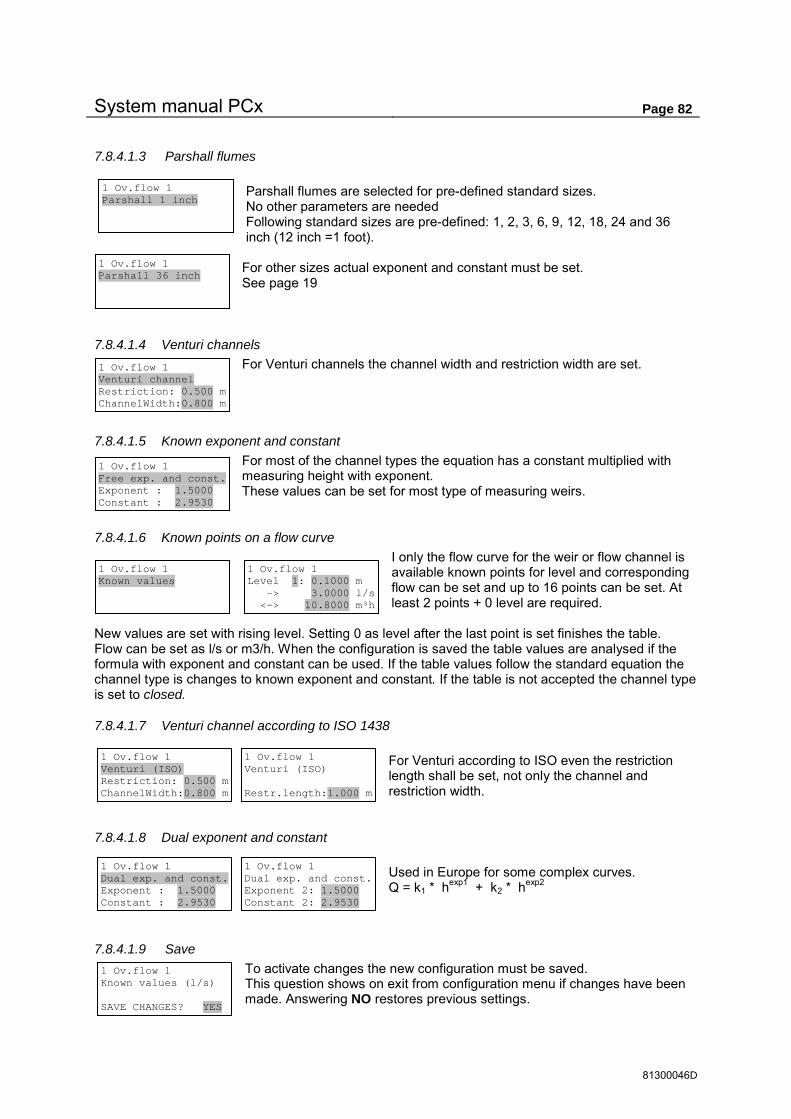
System manual PCx Page 82
81300046D
7.8.4.1.3 Parshall flumes Parshall flumes are selected for pre-defined standard sizes. No other parameters are needed Following standard sizes are pre-defined: 1, 2, 3, 6, 9, 12, 18, 24 and 36 inch (12 inch =1 foot).
For other sizes actual exponent and constant must be set. See page 19
7.8.4.1.4 Venturi channels For Venturi channels the channel width and restriction width are set.
7.8.4.1.5 Known exponent and constant For most of the channel types the equation has a constant multiplied with measuring height with exponent. These values can be set for most type of measuring weirs.
7.8.4.1.6 Known points on a flow curve I only the flow curve for the weir or flow channel is available known points for level and corresponding flow can be set and up to 16 points can be set. At least 2 points + 0 level are required.
New values are set with rising level. Setting 0 as level after the last point is set finishes the table. Flow can be set as l/s or m3/h. When the configuration is saved the table values are analysed if the formula with exponent and constant can be used. If the table values follow the standard equation the channel type is changes to known exponent and constant. If the table is not accepted the channel type is set to closed.
7.8.4.1.7 Venturi channel according to ISO 1438 For Venturi according to ISO even the restriction length shall be set, not only the channel and restriction width.
7.8.4.1.8 Dual exponent and constant Used in Europe for some complex curves. Q = k1 * hexp1 + k2 * hexp2
7.8.4.1.9 Save To activate changes the new configuration must be saved. This question shows on exit from configuration menu if changes have been made. Answering NO restores previous settings.
1 Ov.flow 1 Known values (l/s) SAVE CHANGES? YES
1 Ov.flow 1 Parshall 1 inch
1 Ov.flow 1 Parshall 36 inch
1 Ov.flow 1 Venturi channel Restriction: 0.500 m ChannelWidth:0.800 m
1 Ov.flow 1 Free exp. and const. Exponent : 1.5000 Constant : 2.9530
1 Ov.flow 1 Known values
1 Ov.flow 1 Level 1: 0.1000 m -> 3.0000 l/s <-> 10.8000 m³h
1 Ov.flow 1 Venturi (ISO) Restriction: 0.500 m ChannelWidth:0.800 m
1 Ov.flow 1 Venturi (ISO) Restr.length:1.000 m
1 Ov.flow 1 Dual exp. and const. Exponent : 1.5000 Constant : 2.9530
1 Ov.flow 1 Dual exp. and const. Exponent 2: 1.5000 Constant 2: 2.9530
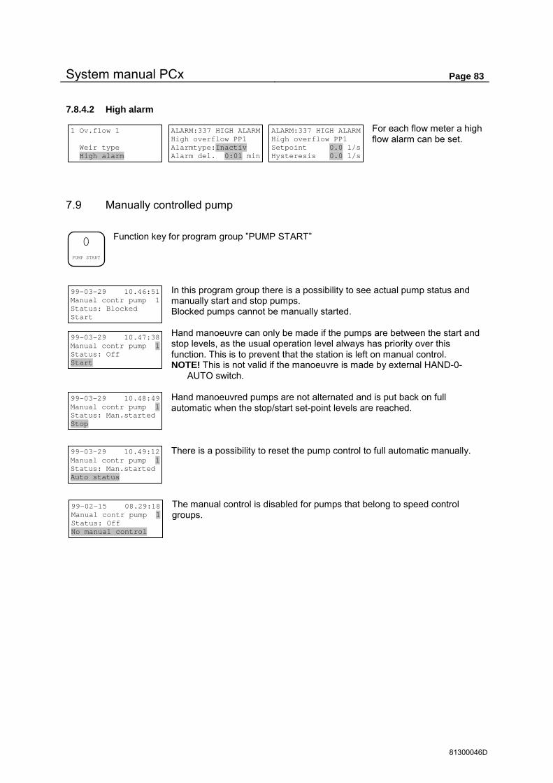
System manual PCx Page 83
81300046D
7.8.4.2 High alarm
For each flow meter a high flow alarm can be set.
7.9 Manually controlled pump
Function key for program group ”PUMP START”
In this program group there is a possibility to see actual pump status and manually start and stop pumps. Blocked pumps cannot be manually started. Hand manoeuvre can only be made if the pumps are between the start and stop levels, as the usual operation level always has priority over this function. This is to prevent that the station is left on manual control. NOTE! This is not valid if the manoeuvre is made by external HAND-0-
AUTO switch. Hand manoeuvred pumps are not alternated and is put back on full automatic when the stop/start set-point levels are reached. There is a possibility to reset the pump control to full automatic manually.
The manual control is disabled for pumps that belong to speed control groups.
1 Ov.flow 1 Weir type High alarm
ALARM:337 HIGH ALARM High overflow PP1 Alarmtype:Inactiv Alarm del. 0:01 min
ALARM:337 HIGH ALARM High overflow PP1 Setpoint 0.0 l/s Hysteresis 0.0 l/s
99-03-29 10.46:51 Manual contr pump 1 Status: Blocked Start 99-03-29 10.47:38 Manual contr pump 1 Status: Off Start
99-03-29 10.48:49 Manual contr pump 1 Status: Man.started Stop
99-03-29 10.49:12 Manual contr pump 1 Status: Man.started Auto status
0
PUMP START
99-02-15 08.29:18 Manual contr pump 1 Status: Off No manual control

System manual PCx Page 84
81300046D
7.10 PID Controller
Function key for program group ”CONTROLLER” See section 6.6 side 28.
In this program group are the Status and all settings for the 2 PID controllers in the PCx viewed and programmed Not used PID controller must be set to CLOSED
7.10.1 Running menu
In the running menu the conditions for the output signal and set-point value are shown also the actual status of ACTUAL VALUE, SET-POINT VALUE and OUTPUT SIGNAL is shown.
7.10.1.1 Output signal auto / manual
This field shows the running condition for the output signal. In position AUTO the output signal is controlled by the controller. In position MAN the output is controlled manually from the panel unit. Own values can be set for the output signal to increase –decrease the signal via the arrow keys.
7.10.1.2 Selection of set-point value
In this field the source for the set-point value is set. In position LSP (Local Set Point) the set-point value is controlled from this menu. External set-point can be used, RSP (Remote Set Point) for value from analogue input, alternatively CSP (Computer Set Point) for remote set-point.
If external set-point is not configured the field for LSP can not be changed.
7.10.2 Programming menu
In the programming menu the basic PID parameters are set, and options for actual value set-point value and output signal.
7.10.2.1 PID Parameters
P. amplification gives the amplification factor for the deviation signal in the controller. I. time gives the integration time and controls the damping time of the controller. D. time gives the derivative time, which calculates the speed of change of the actual value (derivative). See page 28 for description of the parameters for the PID controller. Control direction DIR or REV controls the polarity of the output signal of the controller. DIR gives increasing output signal for set-point value < actual value, REV gives increased output signal if actual value < set-point value. The output signal at 0 deviation gives the possibility to set a basic offset on the output signal and is normally only used when the I and D parameters are not used. The Sampling time is how often the output signal is updated.
PID: 1 DISABLED Runmenue Program menu CONTROLLER CLOSED
.
CONTROLLER
PID: 1 ENABLED Runmenue Program menu CONTROLLER RUNNING
PID: 1 AUTO LSP ACTUAL 0.98 m SETP. 1.30 m OUTSIGNAL 0.0 %
PID: 1 AUTO LSP ACTUAL 0.98 m SETP. 1.30 m OUTSIGNAL 0.0 %
PID: 1 AUTO LSP ACTUAL 0.98 m SETP. 1.30 m OUTSIGNAL 0.0 %
PID: 1 ENABLED Runmenue Program menu CONTROLLER RUNNING
PID: 1 PID Pararmeters Act.value Setp.value Outsignal
PID: 1 PID Pararmeters Act.value Setp.value Outsignal
PID: 1 PID PARAM. P.Ampl 1.000 I.Time 30 sek D.Time 0 sek
PID: 1 PID PARAM. Contr.direction DIR Outsignal at zero- deviation = 0.0 %
PID: 1 PID PARAM. Samplingtime controller 1.0 sek

System manual PCx Page 85
81300046D
7.10.2.2 Actual value
The actual value is connected to an input signal. The range of the input signal of the controller is scaled in technical units.
7.10.2.3 Set-point value
Here are all the basic settings for the set-point value. External set-point value is set to YES if analogue input (RemoteSetPoint) or remote set-point (ComputerSetPoint) is used. At start up there is a possibility to control the set-point to INT, EXT or – as used latest. The setpoint can be limited to a selected range. External set-point value can be connected to an analogue input. For internal set-point value, a start-up set-point can be set to YES to activate a pre-set set-point at start up. If NO is set the latest used set-point is used. If set-point tracking is set to YES the external set-point is copied to the internal when external set-point is active. This is to avoid set-point changes when switching from external to internal set-point.
7.10.2.4 Output signal
The output signal at start up is set to ”– ”to use the latest used settings or ”AUTO” or. ”MAN” For manual position the start up value can be selected. If needed the output signal can be limited to a certain range. Possibility to block the output signal via digital input.
When blocking the output signal, the options can be held at actual value or set to pre-set output signal( block value).
PID: 1 PID Pararmeters Act.value Setp.value Outsignal
PID: 1 ACT.VALUE A.IN Actvalue 1:1 0% = 0.00 m 100% = 10.00 m
PID: 1 PID Pararmeters Act.value Setp.value Outsignal PID: 1 SETPOINT Extern setp val. NO Setpoint type CSP Start setp. - PID: 1 SETPOINT Setpointlimit NO Max setpoint 10.00 Min setpoint 0.00 PID: 1 SETPOINT A.IN Ext.setp. 1:4 Start-up setp. NO Startsetp. 1.00 PID: 1 SETPOINT Setpoint tracking (YES/NO) NO
PID: 1 PID Pararmeters Act.value Setp.value Outsignal
PID: 1 OUTSIGNAL Start (A/M) - Startsignal? NO Startvalue 0.0 %
PID: 1 OUTSIGNAL Outsignallim.? NO Max outsign. 100.0 % Min outsign. 0.0 %
PID: 1 OUTSIGNAL Outsign.block? NO Block. in MAN? NO D.IN Block. 1:0
PID: 1 OUTSIGNAL Actual or blockvalue when blocking BLV Blockvalue 0.0 %

System manual PCx Page 86
81300046D
7.11 Configuration of main menu
The main menu is configured via <ENTER> key when the main menu is active.
In this program group are the setting for the values that are to be shown in the main menu of the display unit.
7.11.1 Signal list
Following signal can be shown in the main menu Signal Index Unit Level pumppit 1-4 0.01 meter Inflow pumppit 1-4 0.1 l/s or m3/h Outflow pumppit 1-4 0.1 l/s or m3/h Overflow pumppit 1-4 0.1 l/s or m3/h Flow meter 1-4 0.1 l/s or m3/h Overflow level pumppit 1-4 0.001 m Level flow meter 1-4 0.001 m Pulse channel 1-8 0.1 unit according to actual configuration IO-module 1 1-4 Analogue input 1-4 according to actual configuration IO-module 2 1-4 IO-module 3 1-4 IO-module 4 1-4 IO-module 5 1-4 IO-module 6 1-4 IO-module 7 1-4 IO-module 8 1-4 Data register 0-12287 Note technical units are not shown for a Data register. PID controller 1-2 0.01 % Actual output signal. Speed PID 1-2 0.01 % Actual speed to frequency converter. Pressure 1-4 0.01 bar Pressure sensor for pumppit 1-4 Suction pressure 1-4 0.01 bar suction pressure sensor for pumppit 1-4 Volume pumppit 1-4 0.001 m3
7.11.2 Display alternatives
7.11.2.1 Fixed values
Display can be selected for date and time + 3 values, or 4 values with 1 value / row. For each value (row) a signal is selected via the arrow keys to allow setting of (pumppit no a.s.o.).
The signal text shown in this type of main menu can be max 9 characters and is copied, if possible, from the associated inputs if the description is max 9 characters. Otherwise the standard texts are used. To have a signal description with longer texts, the option toggle values should be selected.
MAIN MENU 3 values Value 2 = INFLOW PP. SYSTEM PROG
MAIN MENU 3 values Value 2 = INFLOW PP. 1
<ENTER>

System manual PCx Page 87
81300046D
7.11.2.2 Toggled values
Toggled values can be from 2 up to 10 different values. Time shows how long each value is displayed.
This type of main menu shows the signal description on one row (max 20 characters) and measuring values on one row. If possible the signal text is copied from associated input to get more information about the signal. In the toggled main menu the values can be reached via the arrow keys to get information faster if many values are toggled.
7.12 Parameters specific for user
Function key for group ”PARAMETERS”
In this group can user specific parameters be shown or modified. Max. 24 parameters can be assigned for this key by function code 6, F6. Operator access is required to modify parameters. If there are no parameters defined, this text will show up for 3 seconds.
MAIN MENU 2 value- Toggle Time 1 sec INFLOW PP. SYSTEM PROG
MAIN MENU 2 value- Toggle Value 1 = LEVEL PP. 1
Parameter 1 Description text 10 units
6
PARA- METERS
No user parameters defined

System manual PCx Page 88
81300046D
8 Function codes
8.1 Overview
Function key for program group ”FUNCTION”
A function number can be set directly, or stepped with the arrow keys to get an overview of available functions.
8.1.1 Index for function codes in main groups
8.1.1.1 Time functions
Function 100, Date and time ...................................................................................................... 91 Function 110, Timer ................................................................................................................... 91 Function 112, Sequence control with week timer ...................................................................... 92
8.1.1.2 User interface
Function 6, User specific parameters ......................................................................................... 91 Function 120, LED set-up .......................................................................................................... 92 Function 950, Access codes .................................................................................................... 126
8.1.1.3 Zero setting functions
Function 124, Empty alarm list an digital history ........................................................................ 92 Function 125, Zero set pump status ........................................................................................... 92 Function 126, Zero set flow status ............................................................................................. 93 Function 127, Zero set pumppit status ....................................................................................... 93 Function 128, Zero set pulse status ........................................................................................... 93 Function 988, Empty memory .................................................................................................. 126
8.1.1.4 History functions
Function 400, Setting of analogue history ................................................................................. 93 Function 401, Data start register for expanded history .............................................................. 93 Function 405, Set time marking for digital IO history ................................................................. 93 Function 410, Show analogue historic files ............................................................................... 94 Function 415, Show digital IO and alarm history ....................................................................... 94
8.1.1.5 Speed control
Function 600, Ramp time for speed controlled pump ................................................................ 94 Function 610, Override via set-points ........................................................................................ 94 Function 620, Alternation of frequency controlled pump ............................................................ 94 Function 630, Manual alternation of speed controlled pump ..................................................... 94 Function 640, Max difference pressure –suction side ................................................................ 95 Function 650, Pump blocking at low suction pressure ............................................................... 95 Function 660, Limit PID signal when changing pumps ............................................................. 95
8.1.1.6 Settling pit
Function 700, Settling pit ............................................................................................................ 95 Function 701, Status settling pit ................................................................................................. 95
Function 3 <--- FAN ---> SYSTEM PROG
RESET ALARM
FUNCTION

System manual PCx Page 89
81300046D
8.1.1.7 Pump related functions
Function 702, Auto alternation at pump error ............................................................................ 95 Function 703, Pump alternate option ......................................................................................... 95 Function 705, Min time between every change of the pump relay ............................................ 96 Function 706, Flag blocked pumps as hand stopped ................................................................ 96 Function 707, Check run of pump .............................................................................................. 96 Function 708, Pumpcontrol on level derivata ............................................................................ 96 Function 710, Max no. of pumps running simultaneously ......................................................... 96 Function 711, Max no. of pumps running simultaneously in 2 pumppits .................................. 97
8.1.1.8 Communication, modem and alarm calls
Function 401, Data start register for expanded history .............................................................. 93 Function 800, Communication parameter .................................................................................. 98 Function 801, Com port transfer(Com echo) ............................................................................. 98 Function 802, Protocol (Comli/Modbus) parameters for com-ports ........................................... 98 Function 804, Comli/Modbus cross reference ........................................................................... 98 Function 805, Cross reference table for data register ................................................................ 99 Function 806, Cross reference table for IO.bits ......................................................................... 99 Function 807, Scaling of data register with calculated integer data ........................................... 99 Function 808, Free data registers .............................................................................................. 99 Function 809, Error counters on COM ports .............................................................................. 99 Function 810, Hayes init. before calling ..................................................................................... 99 Function 811, Hayes initiation after disconnection ..................................................................... 99 Function 812, No of call signal before modem answer ............................................................ 100 Function 813, Modem initiation ................................................................................................ 100 Function 814, No of alarm call attempts................................................................................... 100 Function 815, Alarm dialling ..................................................................................................... 100 Function 816, Pause time between alarm dialling ................................................................... 101 Function 817, Alarm acknowledgement to stop calling. ........................................................... 101 Function 818, Remote acknowledgement of alarms ................................................................ 101 Function 819, Station identity ................................................................................................... 101 Function 820, GSM sender information for the UCP protocol.................................................. 101 Function 821, GSM receiver for UCP protocol ......................................................................... 101 Function 822, Minicall sender information for THS protocol ................................................... 102 Function 823, Minicall receiver for THS protocol ..................................................................... 102 Function 824, Block alarm dialling when visiting ...................................................................... 102 Function 825, First number for person alarm ........................................................................... 102 Function 826, GSM modem PIN and PUK code ...................................................................... 102 Function 827, GSM modem signal strength ............................................................................. 102 Function 828, Block new alarms when visiting ........................................................................ 102 Function 829, Alarm blocking on power fail ............................................................................. 102 Function 830, Communicaton master configuration ................................................................ 103 Function 831, Comli master messages .................................................................................... 103 Function 832, IO-trig of communication master ....................................................................... 103 Function 833, Modbus master messages ................................................................................ 103 Function 840, IO controlled data register ................................................................................. 104 Function 850, Power save mode .............................................................................................. 104
8.1.1.9 Standard configurations
Function 872, Standard configuration speed controlled pumppit with 2 pumps ...................... 105 Function 873, Standard configuration speed controlled pumppit with 3 pumps ...................... 107 Function 882, Standard configuration speed controlled pumppit with 2 pumps ...................... 109 Function 883, Standard configuration speed controlled pumppit with 3 pumps ...................... 111 Function 888, Standard 2-pump configuration to UCP/UCC standard .................................... 114 Function 890, Simple 2-pump configuration ............................................................................ 116 Function 892, Standard 2-pump configuration ......................................................................... 119 Function 894, Standard 4-pump configuration ......................................................................... 124
System manual PCx Page 90
81300046D
8.1.1.10 Basic information and test, hard ware
These functions are normally not used by the user, mainly used for factory settings and troubleshooting.
Function 2, Time since last boot ................................................................................................ 91 Function 3, Back ground timing .................................................................................................. 91 Function 116, Status and alarms for backup power of IO-modules ........................................... 92 Function 910, Basic calibration of analogue input board ......................................................... 125 Function 911, Calibration of analogue output .......................................................................... 125 Function 913, Baud rate CAN-bus ........................................................................................... 125 Function 914, CAN bus status ................................................................................................. 125 Function 916, Test of serial ports ............................................................................................. 126 Function 923, Test of digital IO ................................................................................................ 126
8.1.1.11 Other
Function 720, Shift motor ........................................................................................................... 97 Function 899, Delivering initiation ............................................................................................ 124 Function 900, Program version ................................................................................................ 125 Function 901, Upgrade information .......................................................................................... 125 Function 902, Serial numbers .................................................................................................. 125

System manual PCx Page 91
81300046D
8.2 Description of all function codes.
8.2.1 Function 2, Time since last boot
Information about restarts and running time since last boot. Used for trouble shooting Possibility to 0 set counter
8.2.2 Function 3, Back ground timing
Shows CPU load for the control program, 0.100 sec = 100%. Actual value can sometimes be up to 1.000 sec but should generally be less than 0.090 sec Max gives the max actual value since last 0 setting.
8.2.3 Function 6, User specific parameters
Up to 24 parameters can be set-up for access by direct key function ”PARAMETERS”. Each parameter is set to ”OFF”, ”READ”, ”SET” or “TIME” for selected data register. For data in double registers the higher register number should be used. Text description can be max. 20 characters and unit max. 6 characters. If “TIME” is selected, no of decimals is automatically set for 2 decimals and data in seconds will read out as mmm:ss For decimal adjustment or data conversion a factor can be set (ex. factor 60 displays data in seconds as whole minutes, or hhh:mm if “TIME” is set).
Max and Min value must be set. Both display and adjustment range is limited to selected span.
8.2.4 Function 100, Date and time
Sets the clock in PCx.
8.2.5 Function 110, Timer
Day / Night timer which are available for digital output type TIMER. Timer 1-4 controls normal/night time for pumppit 1-4. Chose between day or week timer. With day timer the switching is made at the same time all days. With week timer the time is set separately for each day. Timer 5-8 are general day timers for normal/night time and are used to control events repeated 1 time every day. Timer 9 is a general week timer with separate settings for each day.
Function 2 BREAK TIME SINCE BOOT 49567 sec BOOT CNT = 9
Function 3 SET 0. BACKGROUND TIMING Momentan = 0.040 sec Max = 0.048 sec
Function 2 0 SET TIME SINCE BOOT 49603 sec BOOT CNT = 9
Function 100 SET DATE TIME 99-02-06 13.28:01 yy-mm-dd hh.mm:ss
Function 110 Timer 1 PUMPPIT 1 DAY/NIGHT Day time 00:00 h:m Night time 00:00 h:m
Function 110 Timer 1 PUMPPIT 1 WEEKDAYS Day time 00:00 h:m Night time 00:00 h:m Function 110 Timer 1 PUMPPIT 1 Monday Day time 00:00 h:m Night time 00:00 h:m
Function 110 Timer 9 WEEKDAYS Monday On time 00:00 h:m Off time 00:00 h:m
Function 110 Timer 5 GENERAL Day time 00:00 h:m Night time 00:00 h:m
Function 6 Par. 1 OFF Reg. 0 Paramter description Unit Unit Dec. 0 Function 6 Par. 1 Factor 1 Min 0 Unit Max 100000 Unit

System manual PCx Page 92
81300046D
DRIFT /WATCHDOG
LOKAL
A-LARM
B-LARM
LED 1
LED 2
LED 3
LED 5
LED 6
LED 7
LED 8
LED 9
LED 10
LED 13
LED 14
LED 4
LED 11 LED 15
LED 16LED 12
8.2.6 Function 112, Sequence control by week timer
With function 112 up to 64 events be programmed over a week on up to 8 IO-channels. Each event is programmed with week day Monday-Sunday and time as hh:mm, and connected to IO channel 1-8, with new IO-status (0/1), For each event an analogue value (0-65535) can be set. This value is put in a Data register for the IO-channel. These values can then be used further for control or status indications. There are no separate in/out-put types for these events, which only are available IO-bits (976-983 = channel 1-8) for digital status, and register (86-93 = channel 1-8) for analogue status. This to be able to combine the normal functions with IO-bits to get desired control function.
Each switching (1-64) is connected to selected IO-channel. The setting is done with week and time and can be don freely. To allow an easy control it is recommended that the switching is made sequential. New IO status (OFF / ON) can be set for each switching. New value can be set 0-65535 for status indication or used for other data control.
8.2.7 Function 116, Status and alarms for supply voltage of IO-modules
Shows the level of the input voltage for a specific IO-module. An alarm can be trigged on a user specified voltage level.
8.2.8 Function 120, LED set-up
Setting of yellow LED on the panel unit. For each LED following signal choices are available,
Digital output, Digital input, Alarm status, IO-bit, and Blocked
8.2.9 Function 124, Empty alarm list and
digital history
This function erases all 512 events in the digital history. Toggle to 0- SET and press <ENTER> to execute.
8.2.10 Function 125, Zero set pump status
This function sets start and running time counters for all pumps to zero. Toggle to START 0-SETTING and press <ENTER> to execute.
Function 112 Sequence control week timer SYSTEM PROG
Event: 1 Disabled Monday 00:00 New status OFF New value 0 Event: 1 Channel 1 Monday 00:00 New status OFF New value 0
Function 116 MOD 1 Supply: 25.6 VDC Setpoint 10.5 VDC
Function 120 Config. LED 1 Digital output IO mod 1 D.out 1
Function 124 Empty ALARM LIST and Digital history BREAK
Function 125 ZERO - SET PUMP STATUS BREAK

System manual PCx Page 93
81300046D
8.2.11 Function 126, Zero set flow status
This function sets all accumulated volumes for flow meter 1-4.to zero Toggle to START 0-SETTING and then press <ENTER> to execute.
8.2.12 Function 127, Zero set pump pit status
This function sets all accumulated overflows and multiple running times to zero. Toggle to START 0-SETTING and press <ENTER> to execute.
8.2.13 Function 128, Zero set pulse status
This function sets all accumulated pulse volumes for pulse channel 1-8 to zero. Toggle to START 0-SETTING and press <ENTER> to execute.
8.2.14 Function 400, Settings for analogue history
For each signal that is going to be logged, the options interval between log values and log type must be set. The type can be chosen, Closed , Actual value, Average value, Min value or Max value. Logging can be with 16 or 32 bit resolution. 16 bit log can be 2-complement (negative values allowed) or 0-65535 positive values only ( negative value saved as 0). New settings must be confirmed with YES and then <ENTER> before they become valid.
8.2.15 Function 401, Data start register for expanded history
To be able to read compressed historic data directly, it must be expand to the register. A start register for each log channels must be set. 0 or 16384 – 32767. See page 32. For each channel select the day which the expanded data comes from.
8.2.16 Function 405, Setting of time stamp for digital IO history
Time stamping of digital signals is activated separately for each IO-number. IO numbers are grouped for Digital in, Digital out, Pump events or All IO numbers. Toggle between TIME STAMP, DISABLED or ENABLE and confirm with <ENTER>.
Function 126 ZERO - SET FLOW STATUS BREAK
Function 127 ZERO - SET PUMPPIT STATUS BREAK
Function 128 ZERO - SET PULSE VOLUME STATUS BREAK
Function 400 Setup Analogue logger SYSTEM PROG
Function 400 Ch. 0 Log every 5:00 min Average value Level 1
Function 400 Ch. 0 Log every 5:00 min Average value Options
Function 400 Ch. 0 16-bits (2-Kompl.) LEVEL PP. 1 Function 400 Ch. 0 Log every 5:00 min Actual value SAVE CHANGES ? YES
Function 401 Ch. 0 Data startregister for expanded 24 hour log data: 0
Function 405 Setup time stamps on digital IO events SYSTEM PROG
Function 405 IO-Log Dig. in Dig.out Pump events All IO numbers
Function 405 IO 256 DIN 1:1 ALARM INPUT TIME STAMP DISABLED
Function 405 IO 256 DIN 1:1 ALARM INPUT TIME STAMP ENABLED
Function 401 Ch. 0 Expand data for Today

System manual PCx Page 94
81300046D
8.2.17 Function 410, Show analogue historic files
All saved analogue data in the PCx can be shown locally with F.410. The log channels can be switched with the arrow keys, the name of the actual signal is shown on row 4.
For the chosen channel the stored log blocks can be changed via the arrow keys, the log date for the block is shown on the first row. The time is set via the keyboard or with the arrow keys. If the time is changed with the arrow keys and the time passes mid night also the new block number is updated to a new date.
8.2.18 Function 415, Show digital IO and alarm history
Digital story is shown with IO-number, time stamp and IO-text for each stored event. The latest event is shown and earlier events by stepping backwards with the arrow key left, or arrow key right for the
oldest saved event.
8.2.19 Function 600, Ramp times for speed controlled pump
Time ramps are set separately for increasing or decreasing speed. The start-up ramp is only valid for configuration for booster station with slow filling of the pipe after operation interruption. See 6.5
8.2.20 Function 610, Override with set-points
This setting controls the type of speed control. See section 6.5
Set-point OFF (PID) is used for booster stations, ON (PID) for pump pit where the level is to be kept constant, and ON P -BAND where the pit is used to even out the flow for ex. the last pumping pit before the treatment plant.
8.2.21 Function 620, Alternation of frequency controlled pump
Alternation of pumps that are speed controlled can be set from 0-7 times a week. Separate time can be set for each day. When no alternation is wanted on a day the time is set to 0:00 See section 6.5
8.2.22 Function 630, Manual alternating of frequency controlled pump
A selected pump can manually be set to be active speed regulated pump, possible speed regulated pumps can be shown via the arrow keys. During change over the sequence is shown on row 4. See even section 6.5
Function 410 Show Analogue history files SYSTEM PROG
Function 410 990206 Channel 0 Block 1 12:55 1.54 m Level 1
Function 415 Show digital IO and alarm history SYSTEM PROG
Function 415 IO 1123 990206 14.18:49 ALARM 100 ON Fallen tempprot.
Function 600 Timeramp for PID speed controlled SYSTEM PROG
P.speed Timeramp PG1 Increasing 5 sec Decreasing 5 sec Power on 120 sec
Function 610 PG:1 Over ride with setpoints OFF (PID) (Pressure Boost)
Function 610 PG:1 Minimum speed for speed reg. pump: 5 % Function 610 PG:1
Over ride with setpoints ON (PID) (Pumppit)
Function 610 PG:1 Minimum speed 5 % locked speed 90 % After delay:1:00 min
Function 610 PG:1 Over ride with setpoints ON P-BAND (Pumppit)
Function 610 PG:1 Minimum speed 5 % locked speed 90 % After delay:1:00 min
Function 610 PG:1 Start 2.00 m Stop 1.00 m
Function 610 PG:1 Min cap. 1.50 m Max cap. 3.00 m
Function 610 PG:1 Start 2.00 m Stop 1.00 m
Function 620 PG:1 Alternate speed pump Monday 3:00 h:m ( 0:00 = INACTIVE )
Function 630 PG:1 Current speed reg. pump = P 1

System manual PCx Page 95
81300046D
8.2.23 Function 640, Max difference pressure side – suction side
This function is in use when a booster station is controlled with a pressure sensor connected on the suction side. Lowering the set-point value to the PID controller makes the limitation. See section 6.5
8.2.24 Function 650, Pump blocking at low suction pressure
This function is used in booster stations where a pressure sensor is connected on the suction side. If the suction pressure goes below a set value all pumps can be blocked. See section 6.5
8.2.25 Function 660, Limit PID signal at pump change
Without any limitations of the PID regulator, the regulator adjusts the signal toward a set-point value even during a switching sequence of the pumps. This will give the fastest settling time for stations with large flow variations, but can give oscillation with more pump manoeuvres as consequence. This
option can limit that but with slower response time as drawback. See also section 6.5
8.2.26 Function 700, Sedimentation pits
Control of pre settling in sedimentation pits. This function will block pumps in sedimentation pits during pre-set time, to allow for pre-settling after for an ex. heavy rainfall. When the level rises more than the pre-set values the blocking timer is restarted.
Select a sedimentation pit and set settling time. Set-points for rising level for restart of blocking timer is set separately for 0 , 1 and 2 pumps in operation. 3 different set-points can be set for each case of operation.
8.2.27 Function 701, Status sedimentation pit
On row 3 the actual pump status is shown and on row 4 the status of the timer is shown. The timer shows how long time the pumps have been blocked and must reach the set time in F.700 before a pump is started, this is indicated on row 3 ”Timer done”.
8.2.28 Function 702, Auto alternation when pump failure
This function is applicable on most cases where pump alternation is used. When pump alternation is activated, auto alternation at pump failure should be set to ON.
8.2.29 Function 703, Pump alternate option
This setting controls if the pumps should alternate on every pump stop or only when last pump stops (all pumps in pit off). Chose Each pump stop or Last pump stop.
Function 640 PG:1 Max difference In - Out pressure 0.00 bar
Function 660 PG:1 Limit PID during pump switch? NO
Function 700 Sedimentation pit Configuration Setpoints Function 700 Sedimentation pit Configuration Setpoints
Function 700 Sedimentation pit Pumppit 1 Hold time 30:00 h;mm
Function 700 Sedimentation pit Configuration Setpoints
Setpoint 0 pumps 10 cm / 1 min. 15 cm / 3 min. 20 cm / 6 min.
Function 702 PP: 1 Auto alternate on pumpfailure: ON
Function 650 PG:1 Pumphold on low in pressure at 0.00 bar
Function 701 Sedimentation Status Timer done Timer 0:02 h;mm
Function 703 PP: 1 Pump alternate Each pump stop

System manual PCx Page 96
81300046D
8.2.30 Function 705, Min. time between every change of the relays.
The purpose is to protect electrical cabinets and interlocking posts from the high load that a simultaneous start of several pumps can cause. The pump status is unchanged during a set time after a
pump operation.
8.2.31 Function 706, Flag blocked pump as hand stopped
A blocked pump normally returns to auto as soon as the reason of the blocking is fixed. This can sometimes give unwanted pump starts. When a blocked pump is flagged as hand stopped, the pump will not restart before all other pumps in the pit have stopped and/or actual level is over start level for the pump.
8.2.32 Function 707, Check run of pump
This function gives the possibility to make a test run of a pump that has not been used for a certain time (1-999 h). The time for the operation is max 99:59 mm:ss. Pump valve can be checked separately (pump is off during this check) if valve time is entered. The time set should be the max time for opening and closing the valve including the start and open delays. Open command is active until endpoint detection or valve timeout is received, there after a close sequence is started. The pump is blocked until the closing sequence is finished.The check run is allowed if the levels are between these values (NOTE! can be allowed below the normal stop level). No check run will take place for blocked pumps.
8.2.33 Function 708, Pump control on level derivate
This function gives the possibility to start and stop pumps before a level set point depending on the derivate of the level in pit exceeds set point value. Set-points for level derivate is between 1-99 cm/ 1-99 minutes. 0-setting this value will disable this function. Validity for derivate control can be limited for a preset range of pumps running. Setting of valid pump range is done separately for start and stop. Set-points are checked once every minute towards an average value of the level in the pit.
The function allows only 1 pump manoeuvre / minute. If the derivata is still high 1 minute after a previous started pump, the next pump in pit is started a.s.o. Individual start/stop delays for the pumps are ignored. But Common min. delays between pumpstart / pumpstop in pit are still valid. The start sequence for pumps is 1 and the 2 up to 16, depending on how many pumps that is connected to a pump pit. The stop sequence of the pumps is in reverse order, 16-1. This function is only intended for pump pits where pumps are emptying the pit.
8.2.34 Function 710, Max no. of pumps running simultaneously
Set the max. amount of pumps operating simultaneously. Separate setting for each pump pit can be made. Normally combined with auto alternation at pump failure ON in F.702
Function 705 PP 1-4 Min time between every change of pump relais 2 sec
Function 710 PP: 1 Max. no of pumps running together: 0 ( 0=No limitation )
IO-modul:1(1)Dout: 1 NORMALLY OPEN REM.CONTR OUTPUT On time 0:00 mm:ss
Function 706 Flag blocked pump as hand stopped Pump 1 NO
Function 707 P. 1 Checkrun pump after 10 h in off state. Run time: 1:00 min.
Function 708 PP: 1 Level derivata pump- Start: 5 cm/ 1 min Stopp:- 5 cm/ 1 min
Function 707 P. 1 Pumprun allowed if level < 0.00 m or level > 1.00 m
Function 707 P. 1 Separate pump valve manouver: 0:00 min. ( 0 = follows pump )
Function 708 PP: 1 Start condition valid when 0-15 pumps running Function 708 PP: 1 Stop condition valid when 1-16 pumps running

System manual PCx Page 97
81300046D
8.2.35 Function 711, Max no. of pumps running simultaneously in 2 pumppits
Limits the number of pumps in 2 pump pits that are operating simultaneously at the same time. Set which 2 pump pits should have the limit, and the highest number of pumps running at the same time.
8.2.36 Function 720, Shift motor
PCx can control 4 Shift motors. The status menu is the actual and the set-point value shown, and the possibility to set the set-point value.
The configuration menu have are all related settings available. The set-point can be connected to an analogue input or be set manually For analogue input the IO-Module and AI no. is set. The manual set-point is set directly in technical units, which are copied from the analogue input of the actual value.
Even a remote set-point can be set manually. Otherwise set via Data 11611+11612 for shift motor 1, 11635+11636 for shift motor 2, 10153+10154 for
shift motor 3 and 10174+10175 for shift motor 4.
The actual value is connected to an analogue input to send back the signal of the position of shift motor. The position of the end contact can be set to allow for deviation check of the actual value. Deviation status is on IO 872-874 for shift motor 1, 888-890 for shift motor 2, 832-844 for shift motor 3 and 848-860 for shift motor 4. For alarms these IO can be connected to digital in/outputs for free alarm texts. If the deviation of actual value and set-point value is less than the set dead zone no change will be made. Pulse and use time for outputs are set to fit the shift motor. In the status menu the set-point value and the actual value are shown. The different sources for the set-point can be toggled for manual control of the set-point value.
Function 711 Max. no of pumps PP:1 and 2 running together: 0 ( 0=No limitation )
Function 720 Shifting motor 1 Status Configuration Function 720 Shifting motor 1 Status Configuration
Function 720 Setpoint Deadband Feedback Pulsetime Endpoints
Function 720 Setpoint Deadband Feedback Pulsetime Endpoints
Function 720 DISABLE SHIFTMOTOR DISABLED Function 720 A:IN Setpoint 1.54 m IO-Modul:1 AI:1 Levelsensor PP 1 Function 720 MANUAL Setpoint 2.00 m Function 720 REMOTE Setpoint 2.00 m
Function 720 Setpoint Deadband Feedback Pulsetime Endpoints
Function 720 Feedback 1.54 m IO-Modul:1 AI:2 Shift motor position
Function 720 Setpoint Deadband Feedback Pulsetime Endpoints
Function 720 Endpt. MIN: 1.00 m MAX: 3.00 m Hysteres 0.10 m
Function 720 Setpoint Deadband Feedback Pulsetime Endpoints
Function 720 Deadband +- 0.10 m
Function 720 Setpoint Deadband Feedback Pulsetime Endpoints
Function 720 Increase-Decrease Max on time 10 sec Pause time 10 sec
Function 720 Shifting motor 1 Status Configuration
Shifting motor 1 MANUAL Setpoint 2.00 m Feedback 1.54 m
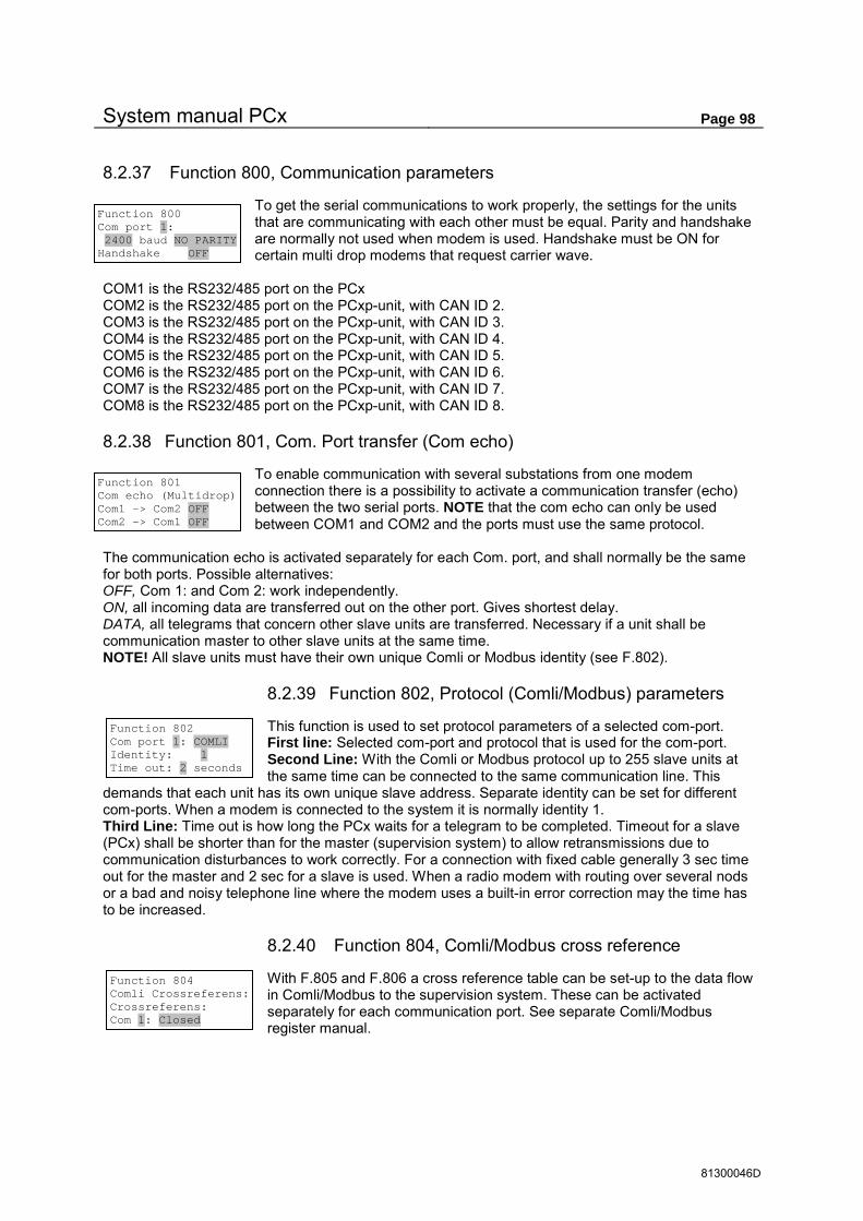
System manual PCx Page 98
81300046D
Function 800 Com port 1: 2400 baud NO PARITY Handshake OFF
8.2.37 Function 800, Communication parameters
To get the serial communications to work properly, the settings for the units that are communicating with each other must be equal. Parity and handshake are normally not used when modem is used. Handshake must be ON for certain multi drop modems that request carrier wave.
COM1 is the RS232/485 port on the PCx COM2 is the RS232/485 port on the PCxp-unit, with CAN ID 2. COM3 is the RS232/485 port on the PCxp-unit, with CAN ID 3. COM4 is the RS232/485 port on the PCxp-unit, with CAN ID 4. COM5 is the RS232/485 port on the PCxp-unit, with CAN ID 5. COM6 is the RS232/485 port on the PCxp-unit, with CAN ID 6. COM7 is the RS232/485 port on the PCxp-unit, with CAN ID 7. COM8 is the RS232/485 port on the PCxp-unit, with CAN ID 8.
8.2.38 Function 801, Com. Port transfer (Com echo)
To enable communication with several substations from one modem connection there is a possibility to activate a communication transfer (echo) between the two serial ports. NOTE that the com echo can only be used between COM1 and COM2 and the ports must use the same protocol.
The communication echo is activated separately for each Com. port, and shall normally be the same for both ports. Possible alternatives: OFF, Com 1: and Com 2: work independently. ON, all incoming data are transferred out on the other port. Gives shortest delay. DATA, all telegrams that concern other slave units are transferred. Necessary if a unit shall be communication master to other slave units at the same time. NOTE! All slave units must have their own unique Comli or Modbus identity (see F.802).
8.2.39 Function 802, Protocol (Comli/Modbus) parameters
This function is used to set protocol parameters of a selected com-port. First line: Selected com-port and protocol that is used for the com-port. Second Line: With the Comli or Modbus protocol up to 255 slave units at the same time can be connected to the same communication line. This
demands that each unit has its own unique slave address. Separate identity can be set for different com-ports. When a modem is connected to the system it is normally identity 1. Third Line: Time out is how long the PCx waits for a telegram to be completed. Timeout for a slave (PCx) shall be shorter than for the master (supervision system) to allow retransmissions due to communication disturbances to work correctly. For a connection with fixed cable generally 3 sec time out for the master and 2 sec for a slave is used. When a radio modem with routing over several nods or a bad and noisy telephone line where the modem uses a built-in error correction may the time has to be increased.
8.2.40 Function 804, Comli/Modbus cross reference
With F.805 and F.806 a cross reference table can be set-up to the data flow in Comli/Modbus to the supervision system. These can be activated separately for each communication port. See separate Comli/Modbus register manual.
Function 801 Com echo (Multidrop) Com1 -> Com2 OFF Com2 -> Com1 OFF
Function 802 Com port 1: COMLI Identity: 1 Time out: 2 seconds
Function 804 Comli Crossreferens: Crossreferens: Com 1: Closed

System manual PCx Page 99
81300046D
8.2.41 Function 805, Cross reference table for data register
For Comli telegram type 0 and 2 the register 0-254 can be set for data for free register 0-12287. Possibility for certain rescaling of data, for ex. running times in seconds can be rescaled to minutes with the factor 60. The scale factor can be between 0-32767. With the factor 0 no rescaling is done.
Certain supervision systems only handle positive values when using the Comli protocol. Settings can be selected for 2-compl. +/-32767 or pure integers 0-65535.If positive numbers are used will 0 be returned for negative values.
8.2.42 Function 806, Cross reference table for IO-bits
For Comli telegrams if type 0, 2, 3 and 4 the IO numbers 0-510 can be set for connecting IO number 0-4095 to those bits
8.2.43 Function 807, Scaling data register with calculated integer data
In data register 5-36 is there a possibility to read the calculated value as integers 0-65535. As these calculated values don’t demand any min and max scaling, there is a possibility here to scale the range for these values. See Comli/Modbus register manual for data register specification.
8.2.44 Function 808, Free data registers
Data register 1960-2047 are free to be used for any data. This function gives the possibility to read / set data in these registers.
8.2.45 Function 809, Error counters on COM ports
These function is showing different telegram info and errors counters on the a selected COM port. The counters have a reset function. The following error counters are available for Checksum, Message, parity, Framing, Overrun, RX buffer full and a break counter.
8.2.46 Function 810, Hayes init. before calling
Certain modems can demand an extra Hayes initiation to work as wanted. This initiation is sent before each call from PCx. New initiation of max 20 digits can be tested with the EXECUTE command. Start AT is not needed.
8.2.47 Function 811, Hayes init after disconnection
This function gives the possibility to change the characteristics of the modem in listening position. This initiation is sent after each time the PCx is disconnected. New initiation of max 20 digits can be tested with the EXECUTE command. Start AT must not be set.
Function 805 Data- register 0 -> 0 Factor 0 (0=def) Pos. numbers 0-65535
Function 806 IO-bit number: 0 coupled to internal IO: 0
Function 807 Scale Data register: 5 0 = 0 l/s 65535 = 100 l/s
Function 808 Free data registers 1960 data: 0
Function 810 Com 1: EXECUTE Hayes init when calling h0e0v1q0
Function 811 Com 1: EXECUTE Hayes reset after disconnecting q0&w
Function 809 Status Com port 1 Telegram OK 30 >Rx buf. full 0

System manual PCx Page 100
81300046D
8.2.48 Function 812, No. of call signals before modem answer
Controls no. of call signals before the modem answers. 0 = auto answer closed. When the number of call signals is changed the new value will be sent to the modem. Status on row 4 shows if modem has accepted the new value.
8.2.49 Function 813, Modem initiation
Function for initiate a modem. At initiation the 12V power supply to the modem is cut for 4 seconds, if it is connected to a digital output. The RTS signal goes low during the same time. The power is set to On and after a 10 sec. delay the default initiation is sent and than PIN code, if GSM modem is
used. Thereafter the number of call signals (F.812), and finally the Hayes reset (F.811) command. Information about the activity and the result are shown on row 4 during initiation. If alarm call is set (F.815) this function runs automatically every 3:rd hour after the latest Comli/Modbus communication with the substation have been made. (Some modems have the ability to freeze unprovoked).
8.2.50 Function 814, No. of alarm call attempts
Highest number of attempts of calling an alarm out. The calling is stopped when the pre-set number of attempts is reached. Every new alarm set the attempt counter to 0 and the PCx is trying again.
8.2.51 Function 815, Alarm dialling
For each alarm number that are set, the Comport connected to the modem must be set. See 6.11.6 page 34 for information about different alarm telephone numbers.
Alarm to GSM telephone with SMS text support. Up to 4 different GSM telephones can be pages. See F.820 and F.821.
Select which alarms shall generate a call function to the supervision system Time out is the longest time for the supervision system to ackn. The call by writing to reg. 333. LC-TRANSLATOR works the same way as the supervision system except that the Comli/Modbus identity is reported as text directly after connection ex.”PCx ID=01”, A delay between the connect command and the ID string can be set.
Telephone number to Minicall is set for wanted baud rate (only for Sweden). See. F 822 and F.823. Up to 4 minicall pagers can be set.
If GSM modem is connected to the PCx, alarms can be sent directly to the GSM telephone with SMS messages. Each GSM operator has his own SMSC no. to be set here.
The GSM number is set in international format with country code without leading 0 in the in the area code.
Function 812 Com 1 Modem answers after 1 callsignals MODEM OK
Function 813 Com 1 Modem init START
Function 814 Abort alarm dialling after 20 retries
Function 815 Alarm no.1 to Com 1: CLOSED Tel: Function 815 Alarm no.1 to Com 1: GSM/BEEPER (UCP) Tel:0740930000
Function 815 Alarm no.1 to Com 1: CENTRAL SYSTEM Tel:086300814 Function 815 Alarm no.1 to Com 1: LC-TRANSL.SYSTEM Tel:086300814
Function 815 Alarm no.1 to Com 1: MINICALL TEXT Tel:086300814
Function 815 Alarm no.1 to Com 1: Max no of messages in 1 call = 2
Function 815 Call C-system on A Alarm on Timeout 2:00 min.
Function 815 Call C-system on A Alarm on Timeout 2:00 min.
Function 815 Alarm no.1 to Com 1: SMS GSM MODEM (PDU) Tel:4670123456
Funktion 815 Short Message Service Center no. +46705008999
Funktion 815 Alarm no.1 på Com 1: Time from CONNECT to ID string 0 sec

System manual PCx Page 101
81300046D
8.2.52 Function 816, Pause time between alarm calls
If the alarm call fails, PCx waits this time before a new attempt is made.
8.2.53 Function 817, Alarm acknowledgement to stop alarm calls.
Setting for acknowledgement type to approve the alarm call. If acknowledgement is missing new attempts will be made up to set max. number in F.814. See page 36 for different types of acknowledgement that can be used.
No acknowledge The calling is stopped when the receiver has answered. Call signal. Acknowledgement is done by calling back. Write to reg. 333 Is selected automatically if the first alarm number is a supervision system. All Data com. Communication with a PC or supervision system acknowledges the alarm.
8.2.54 Function 818, Remote acknowledgement of alarm
If the alarm call is to supervision system there is a possibility here to acknowledge the local alarm list by alarm call acknowledge from the supervision system.
8.2.55 Function 819, Station identity
Station no. 0-9999 are in data register 584 and identifies the station when calling to a supervision system. A name in clear text can be set for the identity when sending alarms to pagers.
8.2.56 Function 820, GSM sender information for UCP
protocol
Most operators for SMS messages to GSM telephones support the UCP protocol.This setting differs between the operators.
8.2.57 Function 821, GSM receiver for UCP protocol
Up to 4 different GSM telephones can be paged. For SMS messages TEXT shall be selected, other types are for future use.
See page. 37. For each receiver this must be set if only station ID, or if all alarms shall be shown in clear text.
Function 816 Pause time between alarmcalls 5:00 minutes
Function 817 Alarmacknow. to stop calls No acknowledge
Function 818 Dist. acknow. all alarms when writing to reg. 333 NO
Function 819 Station no: 1 and name Riverside
Function 820 GSM (UCP-protocol) Send no. 123456 Password
Function 821 GSM (UCP-protocol) Receiver 1 TEXT Number 070123456
Function 821 GSM (UCP-protocol) Text to send: Only station ID Function 821 GSM (UCP-protocol) Text to send: Alarm specification

System manual PCx Page 102
81300046D
8.2.58 Function 822, Minicall sender information for the THS protocol( Sweden only)
To send a minicall message a subscription with Telia is needed to receive a subscriber number and a password. Separate max. baud rate can be set for minicall messages depending on the telephone
number in F.815. See page 35. Minicall alarm is always sent with 7 data bits and even parity. Possibility for extra hayes initiation of modem.
8.2.59 Function 823, Minicall receiver for THS protocol ( Sweden only )
Up to 4 different minicall pagers can be set. Minicall messages can be sent as TEXT, NUMERIC or TONE. Receiver numbers shall be set with area
cod, totally 10 digits. For each receiver can be set if only station ID or all alarms shall be shown in clear text.
8.2.60 Function 824, Block alarm calls when visiting
If the person alarm input is activated in the station there is a possibility to block alarm calls when visiting. If new alarms are not acknowledged these will give alarm calls when this block is lifted. This function can be used as alternative to F.828 when the communication is called through telephone line.
8.2.61 Function 825, First number for person alarm
For person alarm (alarm number 1 and 2) the first alarm call can be set to any of the alarm services which is set in F.815
8.2.62 Function 826, GSM modem PIN and PUK code
The GSM modem needs a SIM card with associated PIN code to activate the modem. The PUK code is normally not needed but will be needed to set a new PIN code if it is not valid. Separate codes can be set for each Comport. Run modem initiation F.813 to execute and verify changes.
8.2.63 Function 827, GSM modem signal strength
This function shows the signal strength 0-31 or 99 if information is missing. See command AT+CSQ in modem manual. A value less than 11 indicates insufficient signal strength. The modem must be initiated with F.813 for correct function. Modem manufacturer and type are shown for information.
8.2.64 Function 828, Block new alarms when visiting
If the personal alarm input is activated in the station is there a possibility to disable new alarms during the visit. All new alarms except the personal alarms (alarm no. 1 and 2) are disabled during the visit. This function is an alternative to F.824 when communication is on a fixed line.
Function 822 MINICALL (THS) modem Send subscr. 900000 Password LOSEN
Function 822 Modem Max 2400 baud Extra hayes init:
Function 823 M.CALL Receiver 1 TEXT Number 0746123456 Ack. code 0
Function 823 M.CALL Receiver 1 TEXT Text to send: Only station ID Function 823 M.CALL Receiver 1 TEXT Text to send: Alarm specification
Function 825 First dialno.(F.815) for personal alarm 1 (Alarm no. 1 and 2)
Function 826 Com 1: GSM modem PIN code 1234 PUK code 12345678
Function 827 Com 1: Siemens M1 Signal 99
Function 824 Alarm dial only on personal alarm when visiting? NO
Function 828 Only personal alarms are active when visiting? NO

System manual PCx Page 103
81300046D
8.2.65 Function 829, Alarm blocking on power fail
When power fail alarm is active may other alarms also be trigged by that power loss. This function can block alarms in such a case. To limit the alarm handling to few alarms. On the unit it is possible to step between alarms and select those that shall be active during a power loss. There is a filter function
that can show only set alarms. The options for an alarm are either Active or blocked during a power loss. The default is that only power loss alarm and personal alarm is active during a power failure.
8.2.66 Function 830, Communication master configuration
Up to 8 master channels can be set. For each type are set type of line (fixed or phone), communications port, Protocol ID for connected slave, and interval timer for how often communication with the slave shall be done. If the interval is set to 0 the timer is shut off. The communication can also be trigged by IO-events, see F.832. NOTE ! Only ONE master on a fixed line. For telephone modem the phone number to the slave must be set. See page 30.
8.2.67 Function 831, Comli master messages
Up to 127 Comli messages can be set. For each message the data/telegram type must be set. Specify local IO/Register number for data. Specify if data is to be read from or be written to the slave. Connect the message to the master channel in F.830. Specify IO/Register number in the Comli slave. Standard register means telegram type 0 and 2. Register 0-3071. Eventual cross reference is ignored. Cross ref. reg. Uses cross reference in F.805. Otherwise the same as standard register. Ext. register uses telegram type < and = for register 0-65535.
8.2.68 Function 832, IO-trig setup of communication master
The com. master can be activated on changes in status of single IO-numbers. Each single IO-number can be set to activate the com. master. IO numbers are grouped as digital in, digital out, pump events and all IO numbers. For each IO number COM.TRIG DISABLED or COM.TRIG ENABLED can be selected.
COMLI MASTER CH. 1 Disabled COM 1 Comli ID 1 Interval 0:00 m:s
Function 830 COMLI MASTER BASIC CONFIGURATION SYSTEM PROG
COMLI MASTER CH. 1 Fix line COM 1 Comli ID 1 Interval 1:00 m:s
COMLI MASTER CH. 1 Phone:123456 COM 1 Comli ID 1 Interval 0:00 m:s
COMLI MASTER MSG 1 Digital IO 0 Read from Master ch.1 IO 0
Function 831 COMLI MASTER IO AND REGISTER CONFIG. SYSTEM PROG
COMLI MASTER MSG 1 Crossref. reg. 0 Write to Master ch.1 R. 0 COMLI MASTER MSG 1 Ext. register 0 Read from Master ch.1 R. 0
Function 832 Setup Com. master IO - trig SYSTEM PROG
Function 832 IO TRIG Dig. in Dig.out Pump events All IO numbers Function 832 IO 256 DIN 1:1 P.1 NOT IN AUTO COM.TRIG DISABLED
COMLI MASTER MSG 1 Register std. 0 Read from Master ch.1 R. 0
Funktion 829 Larmblockering Vid nätfel JA VISA ALLA LARM Funktion 829 Larmblockering Vid nätfel JA VISA UPPSATTA LARM
LARM: 2 SYSTEM Yttre personlarm Vid nätfel är larm AKTIVT

System manual PCx Page 104
81300046D
8.2.69 Function 833, Modbus master messages
Up to 127 Modbus messages can be set. For each message the data/telegram type must be set, COIL IO, Input IO, Hold. Reg., Input reg. Specify local IO/Register number for data. Specify if data is to be read from or be written to the slave. Note that INPUT IO and INPUT register is only read only. Specify IO/Register number in the Modbus slave. Connect the message to the master channel in F.830.
8.2.70 Function 840, IO controlled register data
This function gives the possibility to manipulate data depending on IO status. Up to 16 different IO can be configured. IO-number free of choice is connected to a selected data register. Data is set for IO status 0 and 1. Data can be selected as a numeric value or be collected from another data register
NOTE! There are no restrictions for the choice of data register. This means that a wrong configuration can demolish other parameters and can cause disturbances in the system. Therefore USE THIS FUNCTION WITH OUTMOST CARE.
8.2.71 Function 850, Power save mode
To lower the energy consumption of the unit is there two functions to do this. Especially useful are these when the units is backup powered with batteries.
The first function turns the LED indications off, if a operator panel is connected it takes a little time. The LED indication will be lighten when pressing a Key on the operator panel and then after a little while turns them off again.
NOTE! When this function is in use there is NO indication on the unit that it is on.
The second function sets the processor in a low energy mode.
Function 840 IO controlled Comli data. Function 1 ENABLED
Function 840 IO 0 -> reg. 1960 0 = Value 10 1 = Value 11 Function 840 IO 0 -> reg. 1960 0 = Register 10 1 = Register 11
MODB. MASTER MSG 1 COIL IO 0 Read from Master ch.1 IO 0
Function 831 MODBUS MASTER IO AND REGISTER CONFIG. SYSTEM PROG
COMLI MASTER MSG 1 Holding reg. 0 Write to Master ch.1 R. 0 COMLI MASTER MSG 1 Input register 0 Read from Master ch.1 R. 0
COMLI MASTER MSG 1 Input IO 0 Read from Master ch.1 R. 0
Funktion 850 Energibesparing: LED indikering av NEJ
Funktion 850 Energibesparing: CPU i idle NEJ

System manual PCx Page 105
81300046D
8.2.72 Function 872, Standard configuration speed controlled pumppit with 2
pumps
Basic configuration for a pumppit with 2 pumps and 1 frequency converter. See section 6.5 page 24 about speed control.
Following standard configurations are available. PID WITH M.CURRENT For constant level with PID controller. PID W.O. M.CURRENT P-BAND WITH M.CURRENT For flow equalisation within a level interval. P-BAND W.O. M.CURRENT Function 872 (2-pump configuration for speed control in pumppit): PID without motor currents. executes function 899 (basic initiation). Digital output: 1. NO Pump 1 2. NO Pump 2 4. NO Signal 0-set personal alarm 30 min. delay 5. NO Pump 1 Speed controlled pump 6. NO Pump 2 Speed controlled pump 8. NC Combined alarm output A+B - alarm ON/OFF of speed controlled pump is done with D.OUT 1 and 2. If this is wanted from D.OUT 5 and 6 this can be reset to these outputs. Digital input: 1. NC Block Pump 1 (not auto) 2. NC Block Pump 2 (not auto) 5. NO Fallen motor protector Pump 1 6. NO Fallen motor protector Pump 2 9. NC Fallen temp. protector Pump 1 10. NC Fallen temp. protector Pump 2 16. NO Person alarm - Local mode Analogue input: 1. Level sensor PP.1 4-20 mA = 0-10 meter. Analogue output: 1. Speed signal to frequency converter 4-20 mA = 0-100.00 % LED: 1. Auto position P 1. 2. Start confirmation P 1. 3. Motor protector P 1. 4. Temp. protector P 1. 5. Auto position P 2. 6. Start confirmation P 2. 7. Motor protector P 2. 8. Temp. protector P 2. 16. Signal person alarm timer Alternation fixed pumps: Pump 1: alternation ON. Pump 2: alternation ON..
Function 872 2 PUMP SPEED CONTROLLED PUMPPIT BREAK

System manual PCx Page 106
81300046D
PID 1: Set-point 1.30 m P.Ampl. 5.000 I.time 30 sec. D.time 0 sec. Control action: DIR F.600: Ramp times: Start up: 5 sec. Increasing speed: 5 sec. Decreasing speed: 5 sec. F.610: Control via start start/stop with set-points: ON Start level: 1.50 m Stop level: 0.70 m Set-point value for low speed for switching over to locked speed: 25 % Locked speed: 75 % Time delay before locking: 300 sec. (5 min.) F.620 Time for alternation of speed controlled pump: Each Monday 03:00 F.660 Limit speed when changing pump: OFF F.702 Auto alternation if pump failure: ON Log channel: Signal: Log mode: Interval (sec): 0. Level PP.1 Average 300 Alarm no.: Alarm type: Alarm delay (sec): 1 Person alarm A 180 9 Configuration error B 60 83 Fallen m. protector P1 B 5 84 Fallen temp. protector P1 B 5 99 Fallen m. protector P2 B 5 100 Fallen temp. protector P2 B 5 369 Power fail. IO-module 1 B 60 370 Low voltage 12V B 60 371 IO-module 1 missing A 120 372 AI Board 1 missing A 60 For choice with motor currents add. Analogue input: 2. Current transf. Pump 1 0-20 Ampere 3. Current transf. Pump 2 0-20 Ampere Alarm no: Alarm type: Alarm delay (sec): Set-point 81 High motor curr. P1 B 15 20.0 A 86 No start conf. P1 B 15 2.0 A 97 High motor curr.P2 B 15 20.0 A 102 No start conf. P2 B 15 2.0 A 373 AI board 2 missing B 60 374 AI board 3 missing B 60

System manual PCx Page 107
81300046D
8.2.73 Function 873, Standard configuration speed controlled pumppit with 3 pumps
Basic configuration for a pumppit with 3 pumps and 1 frequency converter. See section 6.5 page 24 about speed control and configuration appendix last in this manual.
Following standard configurations are available. PID WITH M.CURRENT For constant level with PID controller. PID W.O. M.CURRENT P-BAND WITH M.CURRENT For flow equalisation within set level interval. P-BAND W.O. M.CURRENT Function 873 (3-pump configuration for speed control in pumppit): PID without motor currents. executes function 899 (basic initiation). Digital output: 1. NO Pump 1 2. NO Pump 2 3. NO Pump 3 4. NO Signal 0-set personal alarm 30 min. delay 5. NO Pump 1 Speed controlled pump 6. NO Pump 2 Speed controlled pump 7. NO Pump 3 Speed controlled pump 8. NC Combined alarm output A+B - alarm ON/OFF of speed controlled pump is done with D.OUT 1,2 and 3. If this is wanted from D.OUT 5,6 and 7 this can be reset to these outputs. Digital input: 1. NC Block Pump 1 (not auto) 2. NC Block Pump 2 (not auto) 3. NC Block Pump 32 (not auto) 5. NO Fallen motor protector Pump 1 6. NO Fallen motor protector Pump 2 7. NO Fallen motor protector Pump 3 9. NC Fallen temp. protector Pump 1 10. NC Fallen temp. protector Pump 2 11. NC Fallen temp. protector Pump 3 16. NO Person alarm - Local mode Analogue input: 1. Level sensor PP.1 4-20 mA = 0-10 meter. Analogue output: 1. Speed signal to frequency converter 4-20 mA = 0-100.00 % LED: 1. Auto position P 1. 2. Start confirmation P 1. 3. Motor protector P 1. 4. Temp. protector P 1. 5. Auto position P 2. 6. Start confirmation P 2. 7. Motor protector P 2. 8. Temp. protector P 2. 9. Auto position P 3. 10. Start confirmation P 3. 11. Motor protector P 3. 12 . Temp. protector P 3. 16. Signal person alarm timer
Function 873 3 PUMP SPEED CONTROLLED PUMPPIT BREAK

System manual PCx Page 108
81300046D
Alternation fixed pumps: Pump 1: alternation ON. Pump 2: alternation ON.. Pump 3: alternation ON. . PID 1: Set-point 1.30 m P.Ampl. 5.000 I.time 30 sec. D.time 0 sec. Control action: DIR F.600: Ramp times: Start up: 5 sec. Increasing speed: 5 sec. Decreasing speed: 5 sec. F.610: Control via start start/stop with set-points: ON Start level: 1.50 m Stop level: 0.70 m Set-point value for low speed for switching over to locked speed: 25 % Locked speed: 75 % Time delay before locking: 300 sec. (5 min.) F.620 Time for alternation of speed controlled pump: Each Monday 03:00 F.660 Limit speed when changing pump: OFF F.702 Auto alternation when pump failure: ON Log channel: Signal: Log mode: Interval (sec): 0. Level PP.1 Average 300 Alarm no.: Alarm type: Alarm delay (sec): 1 Person alarm A 180 9 Configuration error B 60 83 Fallen m. protector P1 B 5 84 Fallen temp. protector P1 B 5 99 Fallen m. protector P2 B 5 100 Fallen temp. protector P2 B 5 115 Fallen m. protector P3 B 5 116 Fallen temp. protector P3 B 5 369 Power fail. IO-module 1 B 60 370 Low voltage B 60 371 IO-module 1 missing A 120 372 AI Board 1 missing A 60 For choice with motor currents add. Analogue input: 2. Current transf. Pump 1 0-20 Ampere 3. Current transf. Pump 2 0-20 Ampere 4. Current transf. Pump 3 0-20 Ampere Alarm no: Alarm type: Alarm delay (sec): Set-point 81 High motor curr. P1 B 15 20.0 A 86 No start conf. P1 B 15 2.0 A 97 High motor curr.P2 B 15 20.0 A 102 No start conf. P2 B 15 2.0 A 113 High motor curr.P3 B 15 20.0 A 118 No start conf. P3 B 15 2.0 A 373 AI board 2 missing B 60 374 AI board 3 missing B 60 375 AI board 4 missing B 60

System manual PCx Page 109
81300046D
8.2.74 Function 882, Standard configuration pressure boost with 2 pumps
Basic configuration for Booster station with 2 pumps and 1 frequency converter. See section 6.5 page 24 about speed control and configuration appendix in the end of this manual.
Following standard configurations are available. WITH MOTOR CURRENTS For constant pressure with PID controller. WITHOUT MOTOR CURRENT WITH INPUT PRESSURE For pressure limitation at low suction pressure (without motor currents). Function 882 (2-pump configuration for booster station with speed controlled pump): Without Motor currents Executes function 899 (basic initiation). Digital output: 1. NO Pump 1 2. NO Pump 2 4. NO Signal 0-set personal alarm 30 min. delay 5. NO Pump 1 Speed controlled pump 6. NO Pump 2 Speed controlled pump 8. NC Combined alarm output A+B - alarm ON/OFF of speed controlled pump is done with D.OUT 1 and 2. If this is wanted from D.OUT 5 and 6 this can be reset to these outputs Digital input: 1. NC Block Pump 1 (not auto) 2. NC Block Pump 1 (not auto) 5. NO Fallen motor protector Pump 1 6. NO Fallen motor protector Pump 2 9. NC Fallen temp. protector Pump 1 10. NC Fallen temp. protector Pump 2 16. NO Person alarm - Local mode Analogue input: 1. Pressure sensor PP.1 4-20 mA = 0-10 bar. Analogue output:
1. Speed signal to frequency converter 4-20 mA = 0-100.00 % LED: 1. Auto position P 1. 2. Start confirmation P 1. 3. Motor protector P 1. 4. Temp. protector P 1. 5. Auto position P 2. 6. Start confirmation P 2. 7. Motor protector P 2. 8. Temp. protector P 2. 16. Signal person alarm timer PID 1: Set-point 6 bar P.Ampl. 2.000 I.time 30 sec. D.time 0 sec. Control action: REV F.600: Ramp times: Start up: 120 sec. Increasing speed: 5 sec. Decreasing speed: 5 sec.
Function 882 2 PUMP PRESSURE BOOST CONFIGURATION BREAK

System manual PCx Page 110
81300046D
F.610: Control via start start/stop with set-points : ON Set-point for min. speed of speed controlled pump: 5 % F.620 Times for alternation of speed contr. pump: Each Monday 03:00 F.660 Limit speed when changing pump : ON F.702 Auto alternation when pump failure ON Alarm no: Alarm type: Alarm delay (sec): Set-point 1 Person alarm A 180 9 Configuration error B 60 83 Fallen m. protector P1 B 5 84 Fallen temp. protector P1 B 5 99 Fallen m. protector P2 B 5 100 Fallen temp. protector P2 B 5 369 Power fail. IO-module 1 B 60 370 Low voltage 12V B 60 371 IO-module 1 missing A 120 372 AI Board 1 missing A 60 401 High alarm AI 1:1 B 60 10 bar 402 Low alarm AI 1:1 B 60 1 bar Log channel: Signal: Log mode: Interval (sec): 0. Pressure out PP1 Average 300 For choice with motor currents add. Analogue input: 2. Current transf. Pump 1 0-20 Ampere 3. Current transf. Pump 2 0-20 Ampere Alarm no: Alarm type: Alarm delay (sec): Set-point 81 High motor curr. P1 B 15 20.0 A 86 No start conf P1 B 15 2.0 A 97 High motor curr. P2 B 15 20.0 A 102 No start conf P2 B 15 2.0 A 373 AI board 2 missing B 60 374 AI board 3 missing B 60 With suction pressure sensor add. Digital input: 13. NO No start conf. Pump 1 14. NO No start conf Pump 2 Analogue input: 2. Suction pressure sensor PP.1 4-20 mA = 0-10 bar. Alarm no: Alarm type: Alarm delay (sec): 86 No start conf P1 B 15 102 No start conf P2 B 15 373 AI board 2 missing B 60 Log channel: Signal: Log mode: Interval (sec): 1. Suction pressure PP.1 Average 300

System manual PCx Page 111
81300046D
8.2.75 Function 883, Standard configuration pressure boost with 3 pumps
Basic configuration for a Booster station with 3 pumps and 1 frequency converter . See section 6.5 page 24 about speed control and configuration appendix in the end of this manual.
Following standard configurations are available. WITH MOTOR CURRENTS For constant pressure with PID controller WITHOUT MOTOR CURRENT WITH INPUT PRESSURE For pressure limitation at low suction pressure (without motor currents). Function 883 (3-pump configuration for booster station with speed controlled pump): Without Motor currents Execute function 899 (basic initiation). Digital output: 1. NO Pump 1 2. NO Pump 2 3. NO Pump 3 4. NO Signal 0-set personal alarm 30 min. delay 5. NO Pump 1 Speed controlled pump 6. NO Pump 2 Speed controlled pump 7. NO Pump 3 Speed controlled pump 8. NC Combined alarm output A+B - alarm ON/OFF of speed controlled pump is done with D.OUT 1 and 2. If this is wanted from D.OUT 5,6 and 7 this can be reset to these outputs Digital input: 1. NC Block Pump 1 (not auto) 2. NC Block Pump 2 (not auto) 3. NC Block Pump 3 (not auto) 5. NO Fallen motor protector Pump 1 6. NO Fallen motor protector Pump 2 7. NO Fallen motor protector Pump 3 9. NC Fallen temp.protector Pump 1 10. NC Fallen temp.protector Pump 2 11. NC Fallen temp.protector Pump 3 16. NO Person alarm - Local mode Analogue input: 1. Pressure sensor PP.1 4-20 mA = 0-10 bar. Analogue output:
2. Speed signal to frequency converter 4-20 mA = 0-100.00 % LED: 1. Auto position P 1. 2. Start confirmation P 1. 3. Motor protector P 1. 4. Temp.protector P 1. 5. Auto position P 2. 6. Start confirmation P 2. 7. Motor protector P 2. 8. Temp.protector P 2. 9. Auto position P 3. 10. Start confirmation P 3. 11. Motor protector P 3. 12. Temp.protector P 3. 16. Signal person alarm timer
Function 883 3 PUMP PRESSURE BOOST CONFIGURATION BREAK

System manual PCx Page 112
81300046D
Alternation fixed pumps: Pump 1: alternation ON. Pump 2: alternation ON. Pump 3: alternation ON. PID 1: Set-point 6 bar P.Ampl. 2.000 I.time 180 sec. D.time 0 sec. Control action: REV F.600: Ramp times: Start up: 120 sec. Increasing speed: 5 sec. Decreasing speed: 5 sec. F.610: Control via start start/stop with set-points : ON Set-point for min. speed of speed controlled pump: 5 % F.620 Times for alternation of speed contr. pump: Each Monday 03:00 F.660 Limit speed when changing pump : ON F.702 Auto alternation when pump failure ON Alarm no: Alarm type: Alarm delay (sec): Set-point 1 Person alarm A 180 9 Configuration error B 60 83 Fallen m.protector P1 B 5 84 Fallen temp.protector P1 B 5 99 Fallen m.protector P2 B 5 100 Fallen temp.protector P2 B 5 115 Fallen m.protector P3 B 5 116 Fallen temp.protector P3 B 5 369 Power fail. IO-module 1 B 60 370 Low voltage 12V B 60 371 IO-module 1 missing A 120 372 AI Board 1 missing A 60 401 High alarm AI 1:1 B 60 10 bar 402 Low alarm AI 1:1 B 60 1 bar Display shows: Time Speed Control signal PID Outgoing pressure Log channel: Signal: Log mode: Interval (sec): 0. Pressure out PP1 Average 300 For choice with motor currents add. Analogue input: 2. Current transf. Pump 1 0-20 Ampere 3. Current transf. Pump 2 0-20 Ampere 4. Current transf. Pump 3 0-20 Ampere

System manual PCx Page 113
81300046D
Alarm no: Alarm type: Alarm delay (sec): Set-point 81 High motor curr. P1 B 15 20.0 A 86 No start conf P1 B 15 2.0 A 97 High motor curr. P2 B 15 20.0 A 102 No start conf P2 B 15 2.0 A 113 High motor curr P3 B 15 20.0 A 118 No start conf P3 B 15 2.0 A 373 AI board 2 missing B 60 374 AI board 3 missing B 60 375 AI board 4 missing B 60 With suction pressure sensor add. Digital input: 13. NO No start conf. Pump 1 14. NO No start conf Pump 2 15. NO No start conf Pump 3 Analogue input: 2. Suction pressure sensor PP.1 4-20 mA = 0-10 bar. Alarm no: Alarm type: Alarm delay (sec): 86 No start conf P1 B 15 102 No start conf P2 B 15 118 No start conf P3 B 15 373 AI board 2 missing B 60 Row 3 shows suction pressure. Log channel: Signal: Log mode: Interval (sec): 1. Suction pressure PP.1 Average 300

System manual PCx Page 114
81300046D
8.2.76 Function 888, Standard 2 pump configuration according to UCP/UCC
standard
Basic configuration for pump control of 2 pumps. See page 10 about pump control and configuration appendix in the end of the manual
Following standard configurations are available. WITH MOTOR CURRENTS WITHOUT MOTOR CURRENT Function 888 (2-pump config UCP-UCC standard): Execute function 899 (basic initiation). Digital output: : 1. NO Combined alarm output A-alarm 2. NO Combined output alarm B-alarm 3. NO Pump 1 4. NO Pump 2 5. NO Motor protector reset Pump 1 6. NO Motor protector reset Pump 2 8. NO Signal 0-set personal alarm 30 min. delay Digital output: 1. NC Block Pump 1 (not auto) 2. NC Block Pump 2 (not auto) 3. NO Fallen motor protector Pump 1 4. NO Fallen motor protector Pump 2 5. NC Fallen temp. Protector Pump 1 6. NC Fallen temp. Protector Pump 2 7. NO High float PP.1 8. NO Overflow float PP.1 9. NO Person alarm - Local mode Analogue input : 1. Level sensor PP.1 4-20 mA = 0-10 meter. With motor currents 2. Current transformer Pump 1 0-20 Ampere 3. Current transformer Pump 2 0-20 Ampere 9. Indication DIN 9 person alarm input 10. Indication D.OUT 8 Signal person alarm timer 13. Overflow PP.1 14. High float PP.1 Pump 1: Start 1.5 m, Stop 0.7 m, alternation ON. Pump 2: Start 1.6 m, Stop 0.8 m, alternation ON.
Function 888 OLD UCP/UCC 2 PUMP CONFIGURATION BREAK
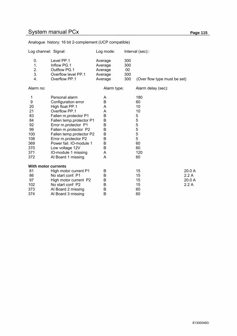
System manual PCx Page 115
81300046D
Analogue history: 16 bit 2-complement (UCP compatible) Log channel: Signal: Log mode: Interval (sec):: 0. Level PP.1 Average 300 1. Inflow PG.1 Average 300 2. Outflow PG.1 Average 00 3. Overflow level PP.1 Average 300 4. Overflow PP.1 Average 300 (Over flow type must be set) Alarm no: Alarm type: Alarm delay (sec): 1 Personal alarm A 180 9 Configuration error B 60 20 High float PP.1 A 10 21 Overflow PP.1 A 10 83 Fallen m.protector P1 B 5 84 Fallen temp.protector P1 B 5 92 Error m.protector P1 B 5 99 Fallen m.protector P2 B 5 100 Fallen temp.protector P2 B 5 108 Error m.protector P2 B 5 369 Power fail. IO-module 1 B 60 370 Low voltage 12V B 60 371 IO-module 1 missing A 120 372 AI Board 1 missing A 60 With motor currents 81 High motor current P1 B 15 20.0 A 86 No start conf. P1 B 15 2.2 A 97 High motor current P2 B 15 20.0 A 102 No start conf P2 B 15 2.2 A 373 AI Board 2 missing B 60 374 AI Board 3 missing B 60

System manual PCx Page 116
81300046D
8.2.77 Function 890, Simple 2- pump configuration
Basic configuration for control of 2 pumps with motor currents. This configuration is the base for all other types in the F.89x series. See section 6.1 page 10 about pump control.
Function 890 (Simple 2-pump configuration): executes function 899 (basic initiation). Digital output: 1. NO Pump 1 2. NO Pump 2 4. NO Signal 0-set personal alarm 30 min. delay 8. NC Combined alarm output A+B - alarm Digital input: 5. NO Fallen m. protector Pump 1 6. NO Fallen m. protector Pump 2 13. NO High float PP.1 14. NO Overflow float PP.1 16. NO Personal alarm - Local mode Analogue input: 1. Level sensor PP.1 4-20 mA = 0-10 meter. LED: 1. Operation P 1 (D.OUT 1:1) 5. Operation P 2 (D.OUT 1:2) 13. Overflow PP.1 14. High float PP.1 16. Signal person alarm timer. Pump 1: Start 1.5 m, Stop 0.7 m, alternation ON. Pump 2: Start 1.6 m, Stop 0.8 m, alternation ON. Analogue history: 16 bit 2-complement (UCP compatible) Log channel: Signal: Log mode: Interval (sec): 0. Level PP.1 Average 300 1. Inflow PP.1 Average 300 2. Outflow PP.1 Average 300 3. Overflow level PP.1 Average 300 4. Overflow PP.1 Average 300 (Overflow type must be set) Alarm no: Alarm type: Alarm delay (sec): Set-point 1 Person alarm A 180 6 High CPU temp. B 60 7 Low voltage 3V B 60 8 3V battery missing B 60 9 Configuration error B 60 17 High level PP.1 A 10 5.00 meter 20 High float PP.1 A 10 21 Overflow PP.1 A 10 83 Fallen m.protector P1 B 5 99 Fallen m.protector P 2 B 5 369 Power fail. IO-module 1 B 60 370 Low voltage 12V B 60 371 IO-module 1 missing A 120 372 AI Board 1 missing A 60
Function 890 BASIC 2 PUMP CONFIGURATION BREAK

System manual PCx Page 117
81300046D
8.2.78 Function 892, Standard 2-pump configuration
Standard configuration for pump control with 2 pumps. See section 6.1 page 10 about pump control and configuration appendix in the end of the manual.
Following standard configurations are available . WITH MOTOR CURRENTS WITHOUT MOTOR CURRENT Function 892 (2-pump configuration): Executes function 899 (basic initiation). Digital output: 1. NO Pump 1 2. NO Pump 2 4. NO Signal 0-set personal alarm 30 min. delay 5. NO Motor protector reset Pump 1 6. NO Motor protector reset Pump 2 8. NC Combined alarm out A+B - alarm Digital inputs: 1. NC Block Pump 1 (not auto) 2. NC Block Pump 2 (not auto) 5. NO Fallen motor protector Pump 1 6. NO Fallen motor protector Pump 2 9. NC Fallen temp. Protector Pump 1 10. NC Fallen temp. Protector Pump 2 13. NO High float PP.1 14. NO Overflow float PP.1 16. NO Person alarm - Local mode Analogue input : 1. Level sensor PP.1 4-20 mA = 0-10 meter. With motor currents 2. Current transformer Pump 1 0-20 Ampere 3. Current transformer Pump 2 0-20 Ampere LED: 1. Auto position P 1. 2. Start confirmation P 1. 3. Motor protector P 1. 4. Temp.protector P 1. 5. Auto position P 2. 6. Start confirmation P 2. 7. Motor protector P 2. 8. Temp.protector P 2. 13. Overflow PP.1 14. High float PP.1 16. Signal person alarm timer Pump 1: Start 1.5 m, Stop 0.7 m, alternation ON. Pump 2: Start 1.6 m, Stop 0.8 m, alternation ON. Analogue history: 16 bit 2-complement (UCP compatible) Log channel: Signal: Log mode: Interval (sec): 0. Level PP.1 Average 300 1. Inflow PG.1 Average 300 2. Outflow PG.1 Average 00 3. Overflow level PP.1 Average 300 4. Overflow PP.1 Average 300 (Over flow type must be set)
Function 892 STANDARD 2 PUMP CONFIGURATION BREAK

System manual PCx Page 118
81300046D
Alarm no: Alarm type: Alarm delay (sec): 1 Personal alarm A 180 9 Configuration error B 60 17 High level PP.1 B 10 5.00 meter 20 High float PP.1 A 10 21 Overflow PP.1 A 10 83 Fallen m.protector P1 B 5 84 Fallen temp.protector P1 B 5 92 Error m.protector P1 B 5 99 Fallen m.protector P2 B 5 100 Fallen temp.protector P2 B 5 108 Error m.protector P2 B 5 369 Power fail. IO-module 1 B 60 370 Low voltage 12V B 60 371 IO-module 1 missing A 120 372 AI Board 1 missing A 60 With motor currents 81 High motor current P1 B 15 20.0 A 86 No start conf P1 B 15 2.0 A 97 High motor current P2 B 15 20.0 A 102 No start conf P2 B 15 2.0 A 373 AI Board 2 missing B 60 374 AI Board 3 missing B 60

System manual PCx Page 119
81300046D
8.2.79 Function 893, Standard 3-pump configuration
Basic configuration for control of 3 pumps with motor currents. See section 6.1 page 10 about pump control and configuration appendix in the end of the manual.
Following standard configurations are available. WITH MOTOR CURRENTS WITHOUT MOTOR CURRENT Function 893 (Standard 3-pump configuration): executes function 899 (basic initiation) and 890. Digital output: 1. NO Pump 1 2. NO Pump 2 3. NO Pump 3 4. NO Signal 0-set personal alarm 30 min. delay 5. NO Motor protector reset Pump 1 6. NO Motor protector reset Pump 2 7. NO Motor protector reset Pump 3 8. NC Combined alarm output A+B - alarm Digital input: 1. NC Block Pump 1 (not auto) 2. NC Block Pump 2 (not auto) 3. NC Block Pump 3 (not auto) 5. NO Fallen motor protector Pump 1 6. NO Fallen motor protector Pump 2 7. NO Fallen motor protector Pump 3 9. NC Fallen temp. Protector Pump 1 10. NC Fallen temp. Protector Pump 2 11. NC Fallen temp. Protector Pump 3 13. NO High float PP.1 14. NO Overflow float PP.1 16. NO Person alarm – Local mode Analogue input : 1. Level sensor PP.1 4-20 mA = 0-10 meter. With motor currents 2. Current transformer Pump 1 0-20 Ampere
3. Current transformer Pump 2 0-20 Ampere 4. Current transformer Pump 3 0-20 Ampere
LED: 1. Auto position P 1. 2. Start confirmation P 1. 3. Motor protector P 1. 4. Temp.protector P 1. 5. Auto position P 2. 6. Start confirmation P 2. 7. Motor protector P 2. 8. Temp.protector P 2. 9. Auto position .P 3. 10. Start confirmation P 3. 11. Motor protector P 3. 12. Temp.protector P 3. 13. Overflow PP.1 14. High float PP.1 16. Signal person alarm timer
Function 893 STANDARD 3 PUMP CONFIGURATION BREAK

System manual PCx Page 120
81300046D
Pump 1: Start 1.5 m, Stop0.7 m, alternation ON. Pump 2: Start 1.6 m, Stop 0.8 m, alternation ON. Pump 3: Start 1.7 m, Stop 0.9 m, alternation ON Analogue history: 16 bit 2-ckomplement (UCP compatible) Log channel: Signal: Log mode: Interval (sec): 0. Level PP.1 Average 300 1. Inflow PP.1 Average 300 2. Outflow PP.1 Average 300 3. Overflow level PP.1 Average 300 4. Overflow PP.1 Average 300 (Overflow type must be set) Alarm no: Alarm type: Alarm delay (sec): Set-point 1 Person alarm A 180 9 Configuration error B 60 17 High level PP.1 B 10 5.00 meter 20 High float PP.1 A 10 21 Overflow PP.1 A 10 83 Fallen m.protector P1 B 5 84 Fallen temp.protector P B 5 92 Error motor protector P1 B 5 99 Fallen m.protector P2 B 5 100 Fallen temp.protector P2 B 5 108 Error motor protector P2 B 5 115 Fallen m.protector P3 B 5 116 Fallen temp.protector P3 B 5 124 Error motor protector P3 B 5 369 Power fail. IO-module 1 B 60 370 Low voltage 12V B 60 371 IO-module 1 missing A 120 372 AI Board 1 missing A 60 with motor currents 81 High motor curr. P1 B 15 20.0 A 86 No start conf P1 B 15 2.0 A 97 High motor curr. P2 B 15 20.0 A 102 No start conf P2 B 15 2.0 A 113 High motor curr. P3 B 15 20.0 A 118 No start conf P3 B 15 2.0 A 373 AI board 2 missing B 60 374 AI board 3 missing B 60 375 AI board 4 missing B 60

System manual PCx Page 121
81300046D
8.2.80 Function 894, Standard 4-pump configuration
Standard for pump control with 4 pumps. See section 6.1 page 10 about pump control.
Following standard configurations are available. WITH MOTOR CURRENTS WITHOUT MOTOR CURRENT Function 894 (4-pump configuration): executes function 899 (basic initiation) and 890. Digital output: 1. NO Pump 1 2. NO Pump 2 3. NO Pump 3 4. NO Pump 4 5. NO Motor protector reset Pump 1 6. NO Motor protector reset Pump 2 7. NO Motor protector reset Pump 3 8. NO Motor protector reset Pump 4 2:7. NO Signal 0-set personal alarm 30 min. delay 2:8. NC Combined alarm output A+B - alarm Digital input: 1. NC Block Pump 1 (not auto) 2. NC Block Pump 1 (not auto) 3. NC Block Pump 1 (not auto) 4. NC Block Pump 1 (not auto) 5. NO Fallen motor protector Pump 1 6. NO Fallen motor protector Pump 2 7. NO Fallen motor protector Pump 3 8. NO Fallen motor protector Pump 4 9. NC Fallen temp. Protector Pump 1 10. NC Fallen temp. Protector Pump 2 11. NC Fallen temp. Protector Pump 3 12. NC Fallen temp. Protector Pump 4 13. NO High float PP.1 14. NO Overflow float PP.1 16. NO Person alarm - Local mode Analogue input : 1. Level sensor PP.1 4-20 mA = 0-10 meter. With motor currents 2. Current transformer Pump 1 0-20 Ampere
5. Current transformer Pump 2 0-20 Ampere 4. Current transformer Pump 3 0-20 Ampere 2:1. Current transformer Pump 4 0-20 Ampere
Function 894 STANDARD 4 PUMP CONFIGURATION BREAK

System manual PCx Page 122
81300046D
LED: 1. Auto position P 1. 2. Start confirmation P 1. 3. Motor protector P 1. 4. Temp.protector P 1. 5. Auto position P 2. 6. Start confirmation P 2. 7. Motor protector P 2. 8. Temp.protector P 2. 9. Auto position .P 3. 10. Start confirmation P 3. 11. Motor protector P 3. 12. Temp.protector P 3. 13. Auto position P 4. 14. Start confirmation P 4. 15. Motor protector P 4. 16. Temp.protector P 4. Pump 1: Start 1.5 m, Stop 0.7 m, alternation ON. Pump 2: Start 1.6 m, Stop 0.8 m, alternation ON. Pump 3: Start 1.7 m, Stop 0.9 m, alternation ON. Pump 4: Start 1.8 m, Stop 1.0 m, alternation ON. Analogue history: 16 bit 2-complement (UCP compatible) Log channel: Signal: Log mode: Interval (sec) 0. Level PP.1 Average 300 1. Inflow PP.1 Average 300 2. Outflow PP.1 Average 300 3. Overflow level PP.1 Average 300 4. Overflow PP.1 Average 300 (Overflow type must be set) Alarm no: Alarm type: Alarm delay (sec): Set-point 1 Person alarm A 180 9 Configuration error B 60 17 High level PP.1 B 10 5.00 meter 20 High float PP.1 A 10 21 Overflow PP.1 A 10 83 Fallen m.protector P1 B 5 84 Fallen temp.protector P1 B 5 92 Error motor protector P1 B 5 99 Fallen m.protector P2 B 5 100 Fallen temp.protector P2 B 5 108 Error motor protector P2 B 5 115 Fallen temp.protector P3 B 5 116 Fallen temp.protector P3 B 5 124 Error motor protector P3 B 5 131 Fallen m.protector P4 B 5 132 Fallen temp.protector P4 B 5 140 Error motor protector P4 B 5 369 Power fail. IO-module 1 B 60 370 Low voltage 12V B 60 371 IO-module 1 missing A 120 372 AI Board 1 missing A 60 433 Power fail. IO-module 2 B 60 434 Low power 12V mod.2 B 60 435 IO-module 2 missing A 120

System manual PCx Page 123
81300046D
with motor currents 81 High motor curr P1 B 15 20.0 A 86 No start conf P1 B 15 2.0 A 97 High motor curr P2 B 15 20.0 A 102 No start conf P2 B 15 2.0 A 113 High motor curr P3 B 15 20.0 A 118 No start conf P3 B 15 2.0 A 129 High motor curr P4 B 15 20.0 A 134 No start conf P4 B 15 2.0 A 373 AI Board 1 missing B 60 374 AI Board 2 missing B 60 375 AI Board 3 missing B 60 436 AI Board 2:1 missing B 60

System manual PCx Page 124
81300046D
8.2.81 Function 899, Delivery initiation
Must be run after resetting memory with F.988. Sets default settings for the unit. If the customer orders no configuration this is the standard configuration at delivery.
For complete erasing of earlier configurations F.988 must be run before starting the configuration: Operator access: 1 System access: 2
All D.in: Closed All D.out: Closed All A.out: Closed A.in 1: Level sensor PP 1 Other A.in: Closed Comport 1-8: 9600,N,8,1 No handshake Comli ID 1 Pumppit parameters PUMPPIT 1-4: Min time between pump starts: 10 sec Pit Area: 3.1 m2 on all points Level points: 0, 1, 2, 3, 4, 5, 6, 7, 8, 9 meter Outflow comp at 2-16 pumps: 95% at 2 pumps, 90% at 3 pumps a.s.o. Pumps EMPTYING pit. Calc. interval inflow: 10 sec. Min level for pumpcap. calc. 0 m. Scaling for Flow reg. 5-12: 0-100 l/s All pumps blocked. Control levels: P1 Start=1.20, Stop=0.70 + 10 cm for each pump ON - OFF delay: 1 sec for all pumps Calc. timer pump capacity: 10 sec for all parameters. Pump curve: 0 for all parameters.
Function 899 FACTORY INITIATION BREAK

System manual PCx Page 125
81300046D
8.2.82 Function 900, Program version
This function shows the program version used in the PCx
8.2.83 Function 901, Upgrade information
Information about upgrade key
8.2.84 Function 902, Serial numbers
Information about Serial number for PCB and PCx
8.2.85 Function 910, basic calibration of the analogue input
This calibration is normally done in the factory and should not be made by the customer.
Calibration is done by connecting calibrated signals to the inputs, for these the raw data is read and stored in a memory chip.
8.2.86 Function 911, Calibration of analogue output
This calibration is made in the factory and should not be made by the customer.
Calibration is done by reading values from the analogue output. From these values a scaling factor is calculated and stored in a memory chip on the IO-module.
8.2.87 Function 913, Baud rate CAN-bus
This setting is made in the factory and should not be made by customer. The data speed for exchange of I/O data between the panel unit and the IO-modules is set to 250 Kbit/s as default value on the PCx and should normally not be changed.
8.2.88 Function 914, CAN-bus status
This function shows the status of the CAN-bus and is used for troubleshooting. Status counters can be set to 0
Function 900 Program version 1.04 Standard English
Function 910 Basic calibration of analogue inputs SYSTEM PROG
Function 910 Ain 1:1 mA input 0/4 - 20 mA CALIBRATE
Function 910 Ain 1:1 AD-Value: 8229 PRESS ENTER TO SET 0 mA
Function 911 Calibrate Anal. out Io-mod:1 Aout:1 Outsignal: 4.000 mA
Function 911 Aout:1:1 read values Value 1 = 4.000 mA Value 2 = 20.000 mA
Function 913 BAUDRATE CAN-BUS 250000 b/s
Function 914 Status CAN bus TX COUNT 12 >RX COUNT 1
Function 901 Free upgrade up to V. 1.99 Act.key:F8 VIEW
Function 902 Serial no 1234567 PCB: 45202199 B- 1 Mf. date: 2002-11-29

System manual PCx Page 126
81300046D
8.2.89 Function 916, Test of serial ports
Function for loop back test of serial ports. TXD and RXD as well as RTS and CTS must be bridged for a selftest.
8.2.90 Function 923, Test of digital IO
This function is used for a loop back test in a test jig at the factory.
8.2.91 Function 950, Access codes
This function can change the codes for the access of operator and system level. The range is 0 – 9999.
8.2.92 Function 988, 0- setting of memory
This function 0- sets the entire memory in the PCx. After 0-setting the PCx restarts and the F.899 must be run for basic initiation. Used to totally erase earlier configurations.
Function 916 SELFTEST OF SERIALPORT No: 1 BAUDRATE 19200
Function 916 TXD = TEST UART1 RXD = RX timeout .....
Function 923 SELFTEST OF DI/DO MODUL NO : 1
Function 950 CHANGE Access codes
Function 988 0-SET RAM MEMORY START 0-SETTING Saved configur. ?
Function 950 CHANGE Access codes Operator code = 1 System code = 2
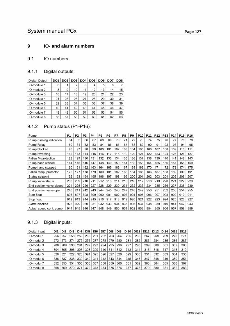
System manual PCx Page 127
81300046D
9 IO- and alarm numbers
9.1 IO numbers
9.1.1 Digital outputs:
Digital Output DO1 DO2 DO3 DO4 DO5 DO6 DO7 DO8 IO-module 1 0 1 2 3 4 5 6 7 IO-module 2 8 9 10 11 12 13 14 15 IO-module 3 16 17 18 19 20 21 22 23 IO-module 4 24 25 26 27 28 29 30 31 IO-module 5 32 33 34 35 36 37 38 39 IO-module 6 40 41 42 43 44 45 46 47 IO-module 7 48 49 50 51 52 53 54 55 IO-module 8 56 57 58 59 60 61 62 63
9.1.2 Pump status (P1-P16):
Pump P1 P2 P3 P4 P5 P6 P7 P8 P9 P10 P11 P12 P13 P14 P15 P16 Pump running indication 64 65 66 67 68 69 70 71 72 73 74 75 76 77 78 79 Pump Relay 80 81 82 83 84 85 86 87 88 89 90 91 92 93 94 95 Pump blocked 96 97 98 99 100 101 102 103 104 105 106 107 108 109 110 111 Pump reversing 112 113 114 115 116 117 118 119 120 121 122 123 124 125 126 127 Fallen M-protection 128 129 130 131 132 133 134 135 136 137 138 139 140 141 142 143 Pump hand started 144 145 146 147 148 149 150 151 152 153 154 155 156 157 158 159 Pump hand stopped 160 161 162 163 164 165 166 167 168 169 170 171 172 173 174 175 Fallen temp. protector 176 177 178 179 180 181 182 183 184 185 186 187 188 189 190 191 Status setpoint 192 193 194 195 196 197 198 199 200 201 202 203 204 205 206 207 Pump valve status 208 209 210 211 212 213 214 215 216 217 218 219 220 221 222 223 End position valve closed 224 225 226 227 228 229 230 231 232 233 234 235 236 237 238 239 End position valve open 240 241 242 243 244 245 246 247 248 249 250 251 252 253 254 255 Start float 896 897 898 899 900 901 902 903 904 905 906 907 908 909 910 911 Stop float 912 913 914 915 916 917 918 919 920 921 922 923 924 925 926 927 Alarm blockad 928 929 930 931 932 933 934 935 936 937 938 939 940 941 942 943 Actual speed cont. pump 944 945 946 947 948 949 950 951 952 953 954 955 956 957 958 959
9.1.3 Digital inputs:
Digital input DI1 DI2 DI3 DI4 DI5 DI6 DI7 DI8 DI9 DI10 DI11 DI12 DI13 DI14 DI15 DI16 IO-modul 1 256 257 258 259 260 261 262 263 264 265 266 267 268 269 270 271 IO-modul 2 272 273 274 275 276 277 278 279 280 281 282 283 284 285 286 287 IO-modul 3 288 289 290 291 292 293 294 295 296 297 298 299 300 301 302 303 IO-modul 4 304 305 306 307 308 309 310 311 312 313 314 315 316 317 318 319 IO-modul 5 320 321 322 323 324 325 326 327 328 329 330 331 332 333 334 335 IO-modul 6 336 337 338 339 340 341 342 343 344 345 346 347 348 349 350 351 IO-modul 7 352 353 354 355 356 357 358 359 360 361 362 363 364 365 366 367 IO-modul 8 368 369 370 371 372 373 374 375 376 377 378 379 380 381 382 383

System manual PCx Page 128
81300046D
9.1.4 Pump pit valves:
PP.1 PP.2 PP.3 PP.4 Valve status: 384 385 386 387 End position closed: 392 393 394 395 End position open: 400 401 402 403
9.1.5 One or more pumps in the pit are blocked trough alarm:
Pump(s) alarm blocked 408 409 410 411
9.1.6 Pump pit status:
PP.1 PP.2 PP.3 PP.4 Sensor error 432 440 448 456 Pump pit blocked 433 441 449 457 Error opening valve 434 442 450 458 Error closing valve 435 443 451 459 Valve error 436 444 452 460 P.P. blocked by valve 437 445 453 461 Not used 438 446 454 462 Not used 439 447 455 463 High level 464 472 480 488 Low level 465 473 481 489 Back-up start 466 474 482 490 High level float 467 475 483 491 Overflow 468 476 484 492 High inflow 469 477 485 493 Low inflow 470 478 486 494 Not used 471 479 487 495
9.1.7 Comb alarm status:
IO-bit Octal Hexadecimal Not ackn. A-Alarm 496 760 1F0 Not ackn B-Alarm 497 761 1F1 Not ackn. C-Alarm 498 762 1F2 Active A-Alarm 504 770 1F8 Active B-Alarm 505 771 1F9 Active C-Alarm 506 772 1FA Ackn Alarm call 511 777 1FF Same as ackn to reg.333 0=PCx disconnects line, 1=System disconnects line.
9.1.8 Free user area:
Can be used freely for ex. remote communication or own programming flags. IO-bit 512-799

System manual PCx Page 129
81300046D
9.1.9 Check run (F.707):
Pump P1 P2 P3 P4 P5 P6 P7 P8 P9 P10 P11 P12 P13 P14 P15 P16 Pump, Check if running 800 801 802 803 804 805 806 807 808 809 810 811 812 813 814 815 Pump valve, Check run. 816 817 818 819 820 821 822 823 824 825 826 827 828 829 830 831
9.1.10 Shift motor:
Shift motor 1 2 3 4 End position MIN 864 880 832 848 End position MAX 865 881 833 849 Blocked 866 882 834 850 Remote position 867 883 835 851 Decrease signal 868 884 836 852 Increase signal 869 885 837 853 DI forced position 870 886 838 854 Error actual value min 872 888 840 856 Error actual value max 873 889 841 857 Error dual end position 874 890 842 858 No A.IN actual value 875 891 843 859 No A.IN set point 876 892 844 860
9.1.11 User IO:
Reserved as user IO 960-967
9.1.12 Status sequential week timer:
Status sequence channel 1-8 976-983
9.1.13 System info:
IO-bit Ackn. Personal alarm 992 Outer personal alarm ON 993 Local mode 994 Modem error 995 Telephone error 996 Configuration Error 1000
9.1.14 Alarm status:
IO-bit Alarm 1=IO 1024 and so on 1024-2047 Alarm status indicates 1 if alarm is active and 0 when alarm is off, independent of alarm type (A, B or C-Alarm). Alarm numbers that are set to ”Inactive” always show 0. For the whole list of alarms check the chapter 9.2.
9.1.15 Latched alarm status:
Alarm 1=IO 2048 and so on 2048-3071 Latched alarm status is set to 1 when an alarm goes active and are updated after a Comli/Modbus readout of actual alarm status. This is made to prevent loosing alarms that have gone inactive before a call is finished. For the whole list of alarms check the chapter 9.2.

System manual PCx Page 130
81300046D
9.1.16 Acknowledged alarms:
Alarm 1=IO 3072 and so on 3072-4095 Status for acknowledged alarms are set to 0 each time a new alarm occurs and gives the possibility for a central system to acknowledge each alarm individually. The acknowledgement works the same way as local acknowledgement on PCx and is made by writing a 1 to actual alarm bit. For the whole list of alarms check the chapter 9.2.
9.1.17 Blocked alarms at Power failure
The IO-bits that controls if an Alarm should be blocked when the Power Fail. Alarm is active are 7168-8047. For the whole list of alarms check the chapter 9.2. 1 = Blocked at Power Fail. Alarm 0 = Not Blocked.
9.1.18 Time stamp of IO-event
Time stamp for change of IO 0-1023. IO 4096 controls time stamp of IO 0 and so on IO-bit 4096-5119
9.1.19 Trig of Com. master communication
Communication trig when changed status on IO 0-1023 (0=OFF 1=ON). IO 5120 controls trig on IO 0 and so on IO-bit 5120-6143
9.1.20 Pump blocking at not ackn. Pump error alarms.
IO number for config. of blocking conditions. 0=No blocking 1=Block until alarm is ackn. Alarm conditions: Pump1 Pump2 Pump3 ... Pump16 High motor current 6144 6152 6160 ... 6264 Low motor current 6145 6153 6161 ... 6265 Fallen motor protector 6146 6154 6162 ... 6266 Fallen temp. protector 6147 6155 6163 ... 6267 Low pump capacity 6148 6156 6164 ... 6268 Running indication missing 6149 6157 6165 ... 6269 Not used 6150 6158 6166 ... 6270 Not used 6151 6159 6167 ... 6271
9.1.21 Setting of new IO status for sequential events.
IO-bit Octal Hexadecimal Sequential event 1-64 6272-6335 14200-14277 1880-18BF

System manual PCx Page 131
81300046D
9.2 Alarm numbers
Alarm nr Alarm group: Alarm text: IO-Number Latch IO Ackno.IO Blocked Alarm 1: SYSTEM Person Alarm 1024 2048 3072 7168 Alarm 2: SYSTEM Ext. Person Alarm 1025 2049 3073 7169 Alarm 3: SYSTEM UC in local mode 1026 2050 3074 7170 Alarm 4: SYSTEM Modem error 1027 2051 3075 7171 Alarm 5: SYSTEM Phone error 1028 2052 3076 7172 Alarm 6: SYSTEM Not used 1029 2053 3077 7173 Alarm 7: SYSTEM Not used 1030 2054 3078 7174 Alarm 8: SYSTEM Not used 1031 2055 3079 7175 Alarm 9: SYSTEM Configuration error 1032 2056 3080 7176 Alarm 10: SYSTEM Not used 1033 2057 3081 7177 Alarm 11: SYSTEM Not used 1034 2058 3082 7178 Alarm 12: SYSTEM Not used 1035 2059 3083 7179 Alarm 13: SYSTEM Not used 1036 2060 3084 7180 Alarm 14: SYSTEM Not used 1037 2061 3085 7181 Alarm 15: SYSTEM Not used 1038 2062 3086 7182 Alarm 16: SYSTEM Not used 1039 2063 3087 7183 Alarm 17: PUMPPIT 1 High level 1040 2064 3088 7184 Alarm 18: PUMPPIT 1 Low level 1041 2065 3089 7185 Alarm 19: PUMPPIT 1 Back-up start 1042 2066 3090 7186 Alarm 20: PUMPPIT 1 High level float 1043 2067 3091 7187 Alarm 21: PUMPPIT 1 Overflow 1044 2068 3092 7188 Alarm 22: PUMPPIT 1 High inflow 1045 2069 3093 7189 Alarm 23: PUMPPIT 1 Low inflow 1046 2070 3094 7190 Alarm 24: PUMPPIT 1 Not used 1047 2071 3095 7191 Alarm 25: PUMPPIT 1 Sensor error 1048 2072 3096 7192 Alarm 26: PUMPPIT 1 Pumps DIN blocked 1049 2073 3097 7193 Alarm 27: PUMPPIT 1 Error opening valve 1050 2074 3098 7194 Alarm 28: PUMPPIT 1 Error closing valve 1051 2075 3099 7195 Alarm 29: PUMPPIT 1 Valve error 1052 2076 3100 7196 Alarm 30: PUMPPIT 1 Pump block valve 1053 2077 3101 7197 Alarm 31: PUMPPIT 1 Not used 1054 2078 3102 7198 Alarm 32: PUMPPIT 1 Not used 1055 2079 3103 7199 Alarm 33: PUMPPIT 2 High level 1056 2080 3104 7200 Alarm 34: PUMPPIT 2 Low level 1057 2081 3105 7201 Alarm 35: PUMPPIT 2 Back-up start 1058 2082 3106 7202 Alarm 36: PUMPPIT 2 High level float 1059 2083 3107 7203 Alarm 37: PUMPPIT 2 Overflow 1060 2084 3108 7204 Alarm 38: PUMPPIT 2 High inflow 1061 2085 3109 7205 Alarm 39: PUMPPIT 2 Low inflow 1062 2086 3110 7206 Alarm 40: PUMPPIT 2 Not used 1063 2087 3111 7207 Alarm 41: PUMPPIT 2 Sensor error 1064 2088 3112 7208 Alarm 42: PUMPPIT 2 Pumps DIN blocked 1065 2089 3113 7209 Alarm 43: PUMPPIT 2 Error opening valve 1066 2090 3114 7210 Alarm 44: PUMPPIT 2 Error closing valve 1067 2091 3115 7211 Alarm 45: PUMPPIT 2 Valve error 1068 2092 3116 7212 Alarm 46: PUMPPIT 2 Pump block valve 1069 2093 3117 7213 Alarm 47: PUMPPIT 2 Not used 1070 2094 3118 7214 Alarm 48: PUMPPIT 2 Not used 1071 2095 3119 7215 Alarm 49: PUMPPIT 3 High level 1072 2096 3120 7216 Alarm 50: PUMPPIT 3 Low level 1073 2097 3121 7217 Alarm 51: PUMPPIT 3 Back-up start 1074 2098 3122 7218 Alarm 52: PUMPPIT 3 High level float 1075 2099 3123 7219 Alarm 53: PUMPPIT 3 Overflow 1076 2100 3124 7220 Alarm 54: PUMPPIT 3 High inflow 1077 2101 3125 7221 Alarm 55: PUMPPIT 3 Low inflow 1078 2102 3126 7222 Alarm 56: PUMPPIT 3 Not used 1079 2103 3127 7223 Alarm 57: PUMPPIT 3 Sensor error 1080 2104 3128 7224 Alarm 58: PUMPPIT 3 Pumps DIN blocked 1081 2105 3129 7225 Alarm 59: PUMPPIT 3 Error opening valve 1082 2106 3130 7226 Alarm 60: PUMPPIT 3 Error closing valve 1083 2107 3131 7227 Alarm 61: PUMPPIT 3 Valve error 1084 2108 3132 7228 Alarm 62: PUMPPIT 3 Pump block valve 1085 2109 3133 7229 Alarm 63: PUMPPIT 3 Not used 1086 2110 3134 7230 Alarm 64: PUMPPIT 3 Not used 1087 2111 3135 7231
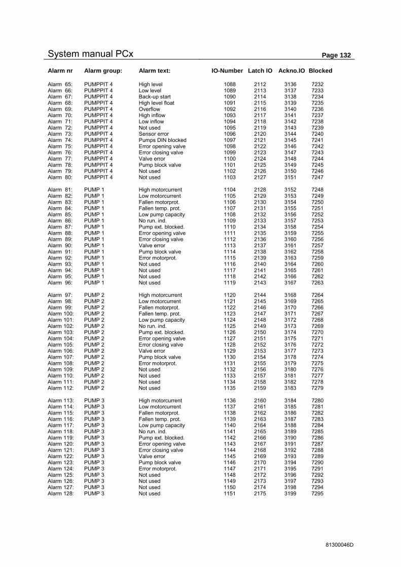
System manual PCx Page 132
81300046D
Alarm nr Alarm group: Alarm text: IO-Number Latch IO Ackno.IO Blocked Alarm 65: PUMPPIT 4 High level 1088 2112 3136 7232 Alarm 66: PUMPPIT 4 Low level 1089 2113 3137 7233 Alarm 67: PUMPPIT 4 Back-up start 1090 2114 3138 7234 Alarm 68: PUMPPIT 4 High level float 1091 2115 3139 7235 Alarm 69: PUMPPIT 4 Overflow 1092 2116 3140 7236 Alarm 70: PUMPPIT 4 High inflow 1093 2117 3141 7237 Alarm 71: PUMPPIT 4 Low inflow 1094 2118 3142 7238 Alarm 72: PUMPPIT 4 Not used 1095 2119 3143 7239 Alarm 73: PUMPPIT 4 Sensor error 1096 2120 3144 7240 Alarm 74: PUMPPIT 4 Pumps DIN blocked 1097 2121 3145 7241 Alarm 75: PUMPPIT 4 Error opening valve 1098 2122 3146 7242 Alarm 76: PUMPPIT 4 Error closing valve 1099 2123 3147 7243 Alarm 77: PUMPPIT 4 Valve error 1100 2124 3148 7244 Alarm 78: PUMPPIT 4 Pump block valve 1101 2125 3149 7245 Alarm 79: PUMPPIT 4 Not used 1102 2126 3150 7246 Alarm 80: PUMPPIT 4 Not used 1103 2127 3151 7247 Alarm 81: PUMP 1 High motorcurrent 1104 2128 3152 7248 Alarm 82: PUMP 1 Low motorcurrent 1105 2129 3153 7249 Alarm 83: PUMP 1 Fallen motorprot. 1106 2130 3154 7250 Alarm 84: PUMP 1 Fallen temp. prot. 1107 2131 3155 7251 Alarm 85: PUMP 1 Low pump capacity 1108 2132 3156 7252 Alarm 86: PUMP 1 No run. ind. 1109 2133 3157 7253 Alarm 87: PUMP 1 Pump ext. blocked. 1110 2134 3158 7254 Alarm 88: PUMP 1 Error opening valve 1111 2135 3159 7255 Alarm 89: PUMP 1 Error closing valve 1112 2136 3160 7256 Alarm 90: PUMP 1 Valve error 1113 2137 3161 7257 Alarm 91: PUMP 1 Pump block valve 1114 2138 3162 7258 Alarm 92: PUMP 1 Error motorprot. 1115 2139 3163 7259 Alarm 93: PUMP 1 Not used 1116 2140 3164 7260 Alarm 94: PUMP 1 Not used 1117 2141 3165 7261 Alarm 95: PUMP 1 Not used 1118 2142 3166 7262 Alarm 96: PUMP 1 Not used 1119 2143 3167 7263 Alarm 97: PUMP 2 High motorcurrent 1120 2144 3168 7264 Alarm 98: PUMP 2 Low motorcurrent 1121 2145 3169 7265 Alarm 99: PUMP 2 Fallen motorprot. 1122 2146 3170 7266 Alarm 100: PUMP 2 Fallen temp. prot. 1123 2147 3171 7267 Alarm 101: PUMP 2 Low pump capacity 1124 2148 3172 7268 Alarm 102: PUMP 2 No run. ind. 1125 2149 3173 7269 Alarm 103: PUMP 2 Pump ext. blocked. 1126 2150 3174 7270 Alarm 104: PUMP 2 Error opening valve 1127 2151 3175 7271 Alarm 105: PUMP 2 Error closing valve 1128 2152 3176 7272 Alarm 106: PUMP 2 Valve error 1129 2153 3177 7273 Alarm 107: PUMP 2 Pump block valve 1130 2154 3178 7274 Alarm 108: PUMP 2 Error motorprot. 1131 2155 3179 7275 Alarm 109: PUMP 2 Not used 1132 2156 3180 7276 Alarm 110: PUMP 2 Not used 1133 2157 3181 7277 Alarm 111: PUMP 2 Not used 1134 2158 3182 7278 Alarm 112: PUMP 2 Not used 1135 2159 3183 7279 Alarm 113: PUMP 3 High motorcurrent 1136 2160 3184 7280 Alarm 114: PUMP 3 Low motorcurrent 1137 2161 3185 7281 Alarm 115: PUMP 3 Fallen motorprot. 1138 2162 3186 7282 Alarm 116: PUMP 3 Fallen temp. prot. 1139 2163 3187 7283 Alarm 117: PUMP 3 Low pump capacity 1140 2164 3188 7284 Alarm 118: PUMP 3 No run. ind. 1141 2165 3189 7285 Alarm 119: PUMP 3 Pump ext. blocked. 1142 2166 3190 7286 Alarm 120: PUMP 3 Error opening valve 1143 2167 3191 7287 Alarm 121: PUMP 3 Error closing valve 1144 2168 3192 7288 Alarm 122: PUMP 3 Valve error 1145 2169 3193 7289 Alarm 123: PUMP 3 Pump block valve 1146 2170 3194 7290 Alarm 124: PUMP 3 Error motorprot. 1147 2171 3195 7291 Alarm 125: PUMP 3 Not used 1148 2172 3196 7292 Alarm 126: PUMP 3 Not used 1149 2173 3197 7293 Alarm 127: PUMP 3 Not used 1150 2174 3198 7294 Alarm 128: PUMP 3 Not used 1151 2175 3199 7295

System manual PCx Page 133
81300046D
Alarm nr Alarm group: Alarm text: IO-Number Latch IO Ackno.IO Blocked Alarm 129: PUMP 4 High motorcurrent 1152 2176 3200 7296 Alarm 130: PUMP 4 Low motorcurrent 1153 2177 3201 7297 Alarm 131: PUMP 4 Fallen motorprot. 1154 2178 3202 7298 Alarm 132: PUMP 4 Fallen temp. prot. 1155 2179 3203 7299 Alarm 133: PUMP 4 Low pump capacity 1156 2180 3204 7300 Alarm 134: PUMP 4 No run. ind. 1157 2181 3205 7301 Alarm 135: PUMP 4 Pump ext. blocked. 1158 2182 3206 7302 Alarm 136: PUMP 4 Error opening valve 1159 2183 3207 7303 Alarm 137: PUMP 4 Error closing valve 1160 2184 3208 7304 Alarm 138: PUMP 4 Valve error 1161 2185 3209 7305 Alarm 139: PUMP 4 Pump block valve 1162 2186 3210 7306 Alarm 140: PUMP 4 Error motorprot. 1163 2187 3211 7307 Alarm 141: PUMP 4 Not used 1164 2188 3212 7308 Alarm 142: PUMP 4 Not used 1165 2189 3213 7309 Alarm 143: PUMP 4 Not used 1166 2190 3214 7310 Alarm 144: PUMP 4 Not used 1167 2191 3215 7311 Alarm 145: PUMP 5 High motorcurrent 1168 2192 3216 7312 Alarm 146: PUMP 5 Low motorcurrent 1169 2193 3217 7313 Alarm 147: PUMP 5 Fallen motorprot. 1170 2194 3218 7314 Alarm 148: PUMP 5 Fallen temp. prot. 1171 2195 3219 7315 Alarm 149: PUMP 5 Low pump capacity 1172 2196 3220 7316 Alarm 150: PUMP 5 No run. ind. 1173 2197 3221 7317 Alarm 151: PUMP 5 Pump ext. blocked. 1174 2198 3222 7318 Alarm 152: PUMP 5 Error opening valve 1175 2199 3223 7319 Alarm 153: PUMP 5 Error closing valve 1176 2200 3224 7320 Alarm 154: PUMP 5 Valve error 1177 2201 3225 7321 Alarm 155: PUMP 5 Pump block valve 1178 2202 3226 7322 Alarm 156: PUMP 5 Error motorprot. 1179 2203 3227 7323 Alarm 157: PUMP 5 Not used 1180 2204 3228 7324 Alarm 158: PUMP 5 Not used 1181 2205 3229 7325 Alarm 159: PUMP 5 Not used 1182 2206 3230 7326 Alarm 160: PUMP 5 Not used 1183 2207 3231 7327 Alarm 161: PUMP 6 High motorcurrent 1184 2208 3232 7328 Alarm 162: PUMP 6 Low motorcurrent 1185 2209 3233 7329 Alarm 163: PUMP 6 Fallen motorprot. 1186 2210 3234 7330 Alarm 164: PUMP 6 Fallen temp. prot. 1187 2211 3235 7331 Alarm 165: PUMP 6 Low pump capacity 1188 2212 3236 7332 Alarm 166: PUMP 6 No run. ind. 1189 2213 3237 7333 Alarm 167: PUMP 6 Pump ext. blocked. 1190 2214 3238 7334 Alarm 168: PUMP 6 Error opening valve 1191 2215 3239 7335 Alarm 169: PUMP 6 Error closing valve 1192 2216 3240 7336 Alarm 170: PUMP 6 Valve error 1193 2217 3241 7337 Alarm 171: PUMP 6 Pump block valve 1194 2218 3242 7338 Alarm 172: PUMP 6 Error motorprot. 1195 2219 3243 7339 Alarm 173: PUMP 6 Not used 1196 2220 3244 7340 Alarm 174: PUMP 6 Not used 1197 2221 3245 7341 Alarm 175: PUMP 6 Not used 1198 2222 3246 7342 Alarm 176: PUMP 6 Not used 1199 2223 3247 7343 Alarm 177: PUMP 7 High motorcurrent 1200 2224 3248 7344 Alarm 178: PUMP 7 Low motorcurrent 1201 2225 3249 7345 Alarm 179: PUMP 7 Fallen motorprot. 1202 2226 3250 7346 Alarm 180: PUMP 7 Fallen temp. prot. 1203 2227 3251 7347 Alarm 181: PUMP 7 Low pump capacity 1204 2228 3252 7348 Alarm 182: PUMP 7 No run. ind. 1205 2229 3253 7349 Alarm 183: PUMP 7 Pump ext. blocked. 1206 2230 3254 7350 Alarm 184: PUMP 7 Error opening valve 1207 2231 3255 7351 Alarm 185: PUMP 7 Error closing valve 1208 2232 3256 7352 Alarm 186: PUMP 7 Valve error 1209 2233 3257 7353 Alarm 187: PUMP 7 Pump block valve 1210 2234 3258 7354 Alarm 188: PUMP 7 Error motorprot. 1211 2235 3259 7355 Alarm 189: PUMP 7 Not used 1212 2236 3260 7356 Alarm 190: PUMP 7 Not used 1213 2237 3261 7357 Alarm 191: PUMP 7 Not used 1214 2238 3262 7358 Alarm 192: PUMP 7 Not used 1215 2239 3263 7359

System manual PCx Page 134
81300046D
Alarm nr Alarm group: Alarm text: IO-Number Latch IO Ackno.IO Blocked Alarm 193: PUMP 8 High motorcurrent 1216 2240 3264 7360 Alarm 194: PUMP 8 Low motorcurrent 1217 2241 3265 7361 Alarm 195: PUMP 8 Fallen motorprot. 1218 2242 3266 7362 Alarm 196: PUMP 8 Fallen temp. prot. 1219 2243 3267 7363 Alarm 197: PUMP 8 Low pump capacity 1220 2244 3268 7364 Alarm 198: PUMP 8 No run. ind. 1221 2245 3269 7365 Alarm 199: PUMP 8 Pump ext. blocked. 1222 2246 3270 7366 Alarm 200: PUMP 8 Error opening valve 1223 2247 3271 7367 Alarm 201: PUMP 8 Error closing valve 1224 2248 3272 7368 Alarm 202: PUMP 8 Valve error 1225 2249 3273 7369 Alarm 203: PUMP 8 Pump block valve 1226 2250 3274 7370 Alarm 204: PUMP 8 Error motorprot. 1227 2251 3275 7371 Alarm 205: PUMP 8 Not used 1228 2252 3276 7372 Alarm 206: PUMP 8 Not used 1229 2253 3277 7373 Alarm 207: PUMP 8 Not used 1230 2254 3278 7374 Alarm 208: PUMP 8 Not used 1231 2255 3279 7375 Alarm 209: PUMP 9 High motorcurrent 1232 2256 3280 7376 Alarm 210: PUMP 9 Low motorcurrent 1233 2257 3281 7377 Alarm 211: PUMP 9 Fallen motorprot. 1234 2258 3282 7378 Alarm 212: PUMP 9 Fallen temp. prot. 1235 2259 3283 7379 Alarm 213: PUMP 9 Low pump capacity 1236 2260 3284 7380 Alarm 214: PUMP 9 No run. ind. 1237 2261 3285 7381 Alarm 215: PUMP 9 Pump ext. blocked. 1238 2262 3286 7382 Alarm 216: PUMP 9 Error opening valve 1239 2263 3287 7383 Alarm 217: PUMP 9 Error closing valve 1240 2264 3288 7384 Alarm 218: PUMP 9 Valve error 1241 2265 3289 7385 Alarm 219: PUMP 9 Pump block valve 1242 2266 3290 7386 Alarm 220: PUMP 9 Error motorprot. 1243 2267 3291 7387 Alarm 221: PUMP 9 Not used 1244 2268 3292 7388 Alarm 222: PUMP 9 Not used 1245 2269 3293 7389 Alarm 223: PUMP 9 Not used 1246 2270 3294 7390 Alarm 224: PUMP 9 Not used 1247 2271 3295 7391 Alarm 225: PUMP 10 High motorcurrent 1248 2272 3296 7392 Alarm 226: PUMP 10 Low motorcurrent 1249 2273 3297 7393 Alarm 227: PUMP 10 Fallen motorprot. 1250 2274 3298 7394 Alarm 228: PUMP 10 Fallen temp. prot. 1251 2275 3299 7395 Alarm 229: PUMP 10 Low pump capacity 1252 2276 3300 7396 Alarm 230: PUMP 10 No run. ind. 1253 2277 3301 7397 Alarm 231: PUMP 10 Pump ext. blocked. 1254 2278 3302 7398 Alarm 232: PUMP 10 Error opening valve 1255 2279 3303 7399 Alarm 233: PUMP 10 Error closing valve 1256 2280 3304 7400 Alarm 234: PUMP 10 Valve error 1257 2281 3305 7401 Alarm 235: PUMP 10 Pump block valve 1258 2282 3306 7402 Alarm 236: PUMP 10 Error motorprot. 1259 2283 3307 7403 Alarm 237: PUMP 10 Not used 1260 2284 3308 7404 Alarm 238: PUMP 10 Not used 1261 2285 3309 7405 Alarm 239: PUMP 10 Not used 1262 2286 3310 7406 Alarm 240: PUMP 10 Not used 1263 2287 3311 7407 Alarm 241: PUMP 11 High motorcurrent 1264 2288 3312 7408 Alarm 242: PUMP 11 Low motorcurrent 1265 2289 3313 7409 Alarm 243: PUMP 11 Fallen motorprot. 1266 2290 3314 7410 Alarm 244: PUMP 11 Fallen temp. prot. 1267 2291 3315 7411 Alarm 245: PUMP 11 Low pump capacity 1268 2292 3316 7412 Alarm 246: PUMP 11 No run. ind. 1269 2293 3317 7413 Alarm 247: PUMP 11 Pump ext. blocked. 1270 2294 3318 7414 Alarm 248: PUMP 11 Error opening valve 1271 2295 3319 7415 Alarm 249: PUMP 11 Error closing valve 1272 2296 3320 7416 Alarm 250: PUMP 11 Valve error 1273 2297 3321 7417 Alarm 251: PUMP 11 Pump block valve 1274 2298 3322 7418 Alarm 252: PUMP 11 Error motorprot. 1275 2299 3323 7419 Alarm 253: PUMP 11 Not used 1276 2300 3324 7420 Alarm 254: PUMP 11 Not used 1277 2301 3325 7421 Alarm 255: PUMP 11 Not used 1278 2302 3326 7422 Alarm 256: PUMP 11 Not used 1279 2303 3327 7423

System manual PCx Page 135
81300046D
Alarm nr Alarm group: Alarm text: IO-Number Latch IO Ackno.IO Blocked Alarm 257: PUMP 12 High motorcurrent 1280 2304 3328 7424 Alarm 258: PUMP 12 Low motorcurrent 1281 2305 3329 7425 Alarm 259: PUMP 12 Fallen motorprot. 1282 2306 3330 7426 Alarm 260: PUMP 12 Fallen temp. prot. 1283 2307 3331 7427 Alarm 261: PUMP 12 Low pump capacity 1284 2308 3332 7428 Alarm 262: PUMP 12 No run. ind. 1285 2309 3333 7429 Alarm 263: PUMP 12 Pump ext. blocked. 1286 2310 3334 7430 Alarm 264: PUMP 12 Error opening valve 1287 2311 3335 7431 Alarm 265: PUMP 12 Error closing valve 1288 2312 3336 7432 Alarm 266: PUMP 12 Valve error 1289 2313 3337 7433 Alarm 267: PUMP 12 Pump block valve 1290 2314 3338 7434 Alarm 268: PUMP 12 Error motorprot. 1291 2315 3339 7435 Alarm 269: PUMP 12 Not used 1292 2316 3340 7436 Alarm 270: PUMP 12 Not used 1293 2317 3341 7437 Alarm 271: PUMP 12 Not used 1294 2318 3342 7438 Alarm 272: PUMP 12 Not used 1295 2319 3343 7439 Alarm 273: PUMP 13 High motorcurrent 1296 2320 3344 7440 Alarm 274: PUMP 13 Low motorcurrent 1297 2321 3345 7441 Alarm 275: PUMP 13 Fallen motorprot. 1298 2322 3346 7442 Alarm 276: PUMP 13 Fallen temp. prot. 1299 2323 3347 7443 Alarm 277: PUMP 13 Low pump capacity 1300 2324 3348 7444 Alarm 278: PUMP 13 No run. ind. 1301 2325 3349 7445 Alarm 279: PUMP 13 Pump ext. blocked. 1302 2326 3350 7446 Alarm 280: PUMP 13 Error opening valve 1303 2327 3351 7447 Alarm 281: PUMP 13 Error closing valve 1304 2328 3352 7448 Alarm 282: PUMP 13 Valve error 1305 2329 3353 7449 Alarm 283: PUMP 13 Pump block valve 1306 2330 3354 7450 Alarm 284: PUMP 13 Error motorprot. 1307 2331 3355 7451 Alarm 285: PUMP 13 Not used 1308 2332 3356 7452 Alarm 286: PUMP 13 Not used 1309 2333 3357 7453 Alarm 287: PUMP 13 Not used 1310 2334 3358 7454 Alarm 288: PUMP 13 Not used 1311 2335 3359 7455 Alarm 289: PUMP 14 High motorcurrent 1312 2336 3360 7456 Alarm 290: PUMP 14 Low motorcurrent 1313 2337 3361 7457 Alarm 291: PUMP 14 Fallen motorprot. 1314 2338 3362 7458 Alarm 292: PUMP 14 Fallen temp. prot. 1315 2339 3363 7459 Alarm 293: PUMP 14 Low pump capacity 1316 2340 3364 7460 Alarm 294: PUMP 14 No run. ind. 1317 2341 3365 7461 Alarm 295: PUMP 14 Pump ext. blocked. 1318 2342 3366 7462 Alarm 296: PUMP 14 Error opening valve 1319 2343 3367 7463 Alarm 297: PUMP 14 Error closing valve 1320 2344 3368 7464 Alarm 298: PUMP 14 Valve error 1321 2345 3369 7465 Alarm 299: PUMP 14 Pump block valve 1322 2346 3370 7466 Alarm 300: PUMP 14 Error motorprot. 1323 2347 3371 7467 Alarm 301: PUMP 14 Not used 1324 2348 3372 7468 Alarm 302: PUMP 14 Not used 1325 2349 3373 7469 Alarm 303: PUMP 14 Not used 1326 2350 3374 7470 Alarm 304: PUMP 14 Not used 1327 2351 3375 7471 Alarm 305: PUMP 15 High motorcurrent 1328 2352 3376 7472 Alarm 306: PUMP 15 Low motorcurrent 1329 2353 3377 7473 Alarm 307: PUMP 15 Fallen motorprot. 1330 2354 3378 7474 Alarm 308: PUMP 15 Fallen temp. prot. 1331 2355 3379 7475 Alarm 309: PUMP 15 Low pump capacity 1332 2356 3380 7476 Alarm 310: PUMP 15 No run. ind. 1333 2357 3381 7477 Alarm 311: PUMP 15 Pump ext. blocked. 1334 2358 3382 7478 Alarm 312: PUMP 15 Error opening valve 1335 2359 3383 7479 Alarm 313: PUMP 15 Error closing valve 1336 2360 3384 7480 Alarm 314: PUMP 15 Valve error 1337 2361 3385 7481 Alarm 315: PUMP 15 Pump block valve 1338 2362 3386 7482 Alarm 316: PUMP 15 Error motorprot. 1339 2363 3387 7483 Alarm 317: PUMP 15 Not used 1340 2364 3388 7484 Alarm 318: PUMP 15 Not used 1341 2365 3389 7485 Alarm 319: PUMP 15 Not used 1342 2366 3390 7486 Alarm 320: PUMP 15 Not used 1343 2367 3391 7487

System manual PCx Page 136
81300046D
Alarm nr Alarm group: Alarm text: IO-Number Latch IO Ackno.IO Blocked Alarm 321: PUMP 16 High motorcurrent 1344 2368 3392 7488 Alarm 322: PUMP 16 Low motorcurrent 1345 2369 3393 7489 Alarm 323: PUMP 16 Fallen motorprot. 1346 2370 3394 7490 Alarm 324: PUMP 16 Fallen temp. prot. 1347 2371 3395 7491 Alarm 325: PUMP 16 Low pump capacity 1348 2372 3396 7492 Alarm 326: PUMP 16 No run. ind. 1349 2373 3397 7493 Alarm 327: PUMP 16 Pump ext. blocked. 1350 2374 3398 7494 Alarm 328: PUMP 16 Error opening valve 1351 2375 3399 7495 Alarm 329: PUMP 16 Error closing valve 1352 2376 3400 7496 Alarm 330: PUMP 16 Valve error 1353 2377 3401 7497 Alarm 331: PUMP 16 Pump block valve 1354 2378 3402 7498 Alarm 332: PUMP 16 Error motorprot. 1355 2379 3403 7499 Alarm 333: PUMP 16 Not used 1356 2380 3404 7500 Alarm 334: PUMP 16 Not used 1357 2381 3405 7501 Alarm 335: PUMP 16 Not used 1358 2382 3406 7502 Alarm 336: PUMP 16 Not used 1359 2383 3407 7503 Alarm 337: HIGH ALARM High Overflow PP1 1360 2384 3408 7504 Alarm 338: HIGH ALARM High Overflow PP2 1361 2385 3409 7505 Alarm 339: HIGH ALARM High Overflow PP3 1362 2386 3410 7506 Alarm 340: HIGH ALARM High Overflow PP4 1363 2387 3411 7507 Alarm 341: HIGH ALARM High Flow FM1 1364 2388 3412 7508 Alarm 342: HIGH ALARM High Flow FM2 1365 2389 3413 7509 Alarm 343: HIGH ALARM High Flow FM3 1366 2390 3414 7510 Alarm 344: HIGH ALARM High Flow FM4 1367 2391 3415 7511 Alarm 345: HIGH ALARM HIGH ALARM Puls.ch..1 1368 2392 3416 7512 Alarm 346: HIGH ALARM HIGH ALARM Puls.ch..2 1369 2393 3417 7513 Alarm 347: HIGH ALARM HIGH ALARM Puls.ch..3 1370 2394 3418 7514 Alarm 348: HIGH ALARM HIGH ALARM Puls.ch..4 1371 2395 3419 7515 Alarm 349: HIGH ALARM HIGH ALARM Puls.ch..5 1372 2396 3420 7516 Alarm 350: HIGH ALARM HIGH ALARM Puls.ch..6 1373 2397 3421 7517 Alarm 351: HIGH ALARM HIGH ALARM Puls.ch..7 1374 2398 3422 7518 Alarm 352: HIGH ALARM HIGH ALARM Puls.ch..8 1375 2399 3423 7519 Alarm 353: REM. COM. Com. err Master ch.1 1376 2400 3424 7520 Alarm 354: REM. COM. Err. when calling1 1377 2401 3425 7521 Alarm 355: REM. COM. Com. err Master ch.2 1378 2402 3426 7522 Alarm 356: REM. COM. Err. when calling2 1379 2403 3427 7523 Alarm 357: REM. COM. Com. err Master ch.3 1380 2404 3428 7524 Alarm 358: REM. COM. Err. when calling3 1381 2405 3429 7525 Alarm 359: REM. COM. Com. err Master ch.4 1382 2406 3430 7526 Alarm 360: REM. COM. Err. when calling4 1383 2407 3431 7527 Alarm 361: REM. COM. Com. err Master ch.5 1384 2408 3432 7528 Alarm 362: REM. COM. Err. when calling5 1385 2409 3433 7529 Alarm 363: REM. COM. Com. err Master ch.6 1386 2410 3434 7530 Alarm 364: REM. COM. Err. when calling6 1387 2411 3435 7531 Alarm 365: REM. COM. Com. err Master ch.7 1388 2412 3436 7532 Alarm 366: REM. COM. Err. when calling7 1389 2413 3437 7533 Alarm 367: REM. COM. Com. err Master ch.8 1390 2414 3438 7534 Alarm 368: REM. COM. Err. when calling8 1391 2415 3439 7535 Alarm 369: IO MODUL 1 Power failure 1392 2416 3440 7536 Alarm 370: IO MODUL 1 Low voltage 12V 1393 2417 3441 7537 Alarm 371: IO MODUL 1 IO module missing 1394 2418 3442 7538 Alarm 372: IO MODUL 1 AI board 1 missing 1395 2419 3443 7539 Alarm 373: IO MODUL 1 AI board 2 missing 1396 2420 3444 7540 Alarm 374: IO MODUL 1 AI board 3 missing 1397 2421 3445 7541 Alarm 375: IO MODUL 1 AI board 4 missing 1398 2422 3446 7542 Alarm 376: IO MODUL 1 Not used 1399 2423 3447 7543 Alarm 377: IO MODUL 1 Not used 1400 2424 3448 7544 Alarm 378: IO MODUL 1 Not used 1401 2425 3449 7545 Alarm 379: IO MODUL 1 Not used 1402 2426 3450 7546 Alarm 380: IO MODUL 1 Not used 1403 2427 3451 7547 Alarm 381: IO MODUL 1 Not used 1404 2428 3452 7548 Alarm 382: IO MODUL 1 Not used 1405 2429 3453 7549 Alarm 383: IO MODUL 1 Not used 1406 2430 3454 7550 Alarm 384: IO MODUL 1 Not used 1407 2431 3455 7551
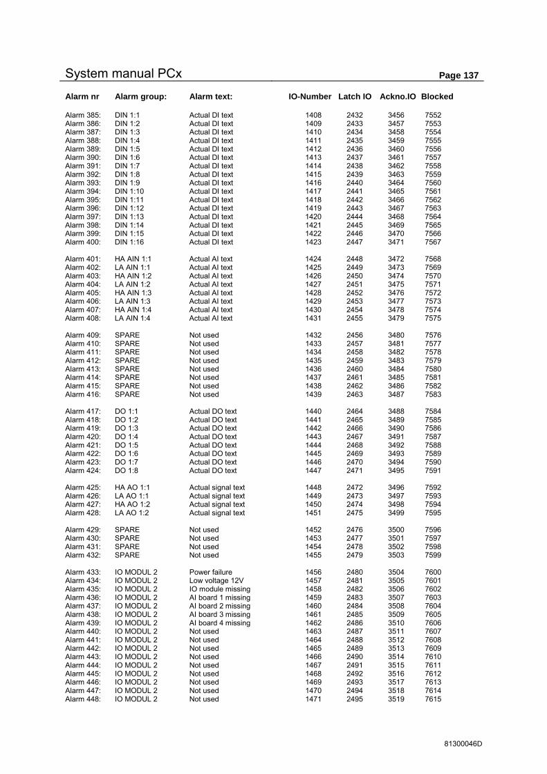
System manual PCx Page 137
81300046D
Alarm nr Alarm group: Alarm text: IO-Number Latch IO Ackno.IO Blocked Alarm 385: DIN 1:1 Actual DI text 1408 2432 3456 7552 Alarm 386: DIN 1:2 Actual DI text 1409 2433 3457 7553 Alarm 387: DIN 1:3 Actual DI text 1410 2434 3458 7554 Alarm 388: DIN 1:4 Actual DI text 1411 2435 3459 7555 Alarm 389: DIN 1:5 Actual DI text 1412 2436 3460 7556 Alarm 390: DIN 1:6 Actual DI text 1413 2437 3461 7557 Alarm 391: DIN 1:7 Actual DI text 1414 2438 3462 7558 Alarm 392: DIN 1:8 Actual DI text 1415 2439 3463 7559 Alarm 393: DIN 1:9 Actual DI text 1416 2440 3464 7560 Alarm 394: DIN 1:10 Actual DI text 1417 2441 3465 7561 Alarm 395: DIN 1:11 Actual DI text 1418 2442 3466 7562 Alarm 396: DIN 1:12 Actual DI text 1419 2443 3467 7563 Alarm 397: DIN 1:13 Actual DI text 1420 2444 3468 7564 Alarm 398: DIN 1:14 Actual DI text 1421 2445 3469 7565 Alarm 399: DIN 1:15 Actual DI text 1422 2446 3470 7566 Alarm 400: DIN 1:16 Actual DI text 1423 2447 3471 7567 Alarm 401: HA AIN 1:1 Actual AI text 1424 2448 3472 7568 Alarm 402: LA AIN 1:1 Actual AI text 1425 2449 3473 7569 Alarm 403: HA AIN 1:2 Actual AI text 1426 2450 3474 7570 Alarm 404: LA AIN 1:2 Actual AI text 1427 2451 3475 7571 Alarm 405: HA AIN 1:3 Actual AI text 1428 2452 3476 7572 Alarm 406: LA AIN 1:3 Actual AI text 1429 2453 3477 7573 Alarm 407: HA AIN 1:4 Actual AI text 1430 2454 3478 7574 Alarm 408: LA AIN 1:4 Actual AI text 1431 2455 3479 7575 Alarm 409: SPARE Not used 1432 2456 3480 7576 Alarm 410: SPARE Not used 1433 2457 3481 7577 Alarm 411: SPARE Not used 1434 2458 3482 7578 Alarm 412: SPARE Not used 1435 2459 3483 7579 Alarm 413: SPARE Not used 1436 2460 3484 7580 Alarm 414: SPARE Not used 1437 2461 3485 7581 Alarm 415: SPARE Not used 1438 2462 3486 7582 Alarm 416: SPARE Not used 1439 2463 3487 7583 Alarm 417: DO 1:1 Actual DO text 1440 2464 3488 7584 Alarm 418: DO 1:2 Actual DO text 1441 2465 3489 7585 Alarm 419: DO 1:3 Actual DO text 1442 2466 3490 7586 Alarm 420: DO 1:4 Actual DO text 1443 2467 3491 7587 Alarm 421: DO 1:5 Actual DO text 1444 2468 3492 7588 Alarm 422: DO 1:6 Actual DO text 1445 2469 3493 7589 Alarm 423: DO 1:7 Actual DO text 1446 2470 3494 7590 Alarm 424: DO 1:8 Actual DO text 1447 2471 3495 7591 Alarm 425: HA AO 1:1 Actual signal text 1448 2472 3496 7592 Alarm 426: LA AO 1:1 Actual signal text 1449 2473 3497 7593 Alarm 427: HA AO 1:2 Actual signal text 1450 2474 3498 7594 Alarm 428: LA AO 1:2 Actual signal text 1451 2475 3499 7595 Alarm 429: SPARE Not used 1452 2476 3500 7596 Alarm 430: SPARE Not used 1453 2477 3501 7597 Alarm 431: SPARE Not used 1454 2478 3502 7598 Alarm 432: SPARE Not used 1455 2479 3503 7599 Alarm 433: IO MODUL 2 Power failure 1456 2480 3504 7600 Alarm 434: IO MODUL 2 Low voltage 12V 1457 2481 3505 7601 Alarm 435: IO MODUL 2 IO module missing 1458 2482 3506 7602 Alarm 436: IO MODUL 2 AI board 1 missing 1459 2483 3507 7603 Alarm 437: IO MODUL 2 AI board 2 missing 1460 2484 3508 7604 Alarm 438: IO MODUL 2 AI board 3 missing 1461 2485 3509 7605 Alarm 439: IO MODUL 2 AI board 4 missing 1462 2486 3510 7606 Alarm 440: IO MODUL 2 Not used 1463 2487 3511 7607 Alarm 441: IO MODUL 2 Not used 1464 2488 3512 7608 Alarm 442: IO MODUL 2 Not used 1465 2489 3513 7609 Alarm 443: IO MODUL 2 Not used 1466 2490 3514 7610 Alarm 444: IO MODUL 2 Not used 1467 2491 3515 7611 Alarm 445: IO MODUL 2 Not used 1468 2492 3516 7612 Alarm 446: IO MODUL 2 Not used 1469 2493 3517 7613 Alarm 447: IO MODUL 2 Not used 1470 2494 3518 7614 Alarm 448: IO MODUL 2 Not used 1471 2495 3519 7615

System manual PCx Page 138
81300046D
Alarm nr Alarm group: Alarm text: IO-Number Latch IO Ackno.IO Blocked Alarm 449: DIN 2:1 Actual DI text 1472 2496 3520 7616 Alarm 450: DIN 2:2 Actual DI text 1473 2497 3521 7617 Alarm 451: DIN 2:3 Actual DI text 1474 2498 3522 7618 Alarm 452: DIN 2:4 Actual DI text 1475 2499 3523 7619 Alarm 453: DIN 2:5 Actual DI text 1476 2500 3524 7620 Alarm 454: DIN 2:6 Actual DI text 1477 2501 3525 7621 Alarm 455: DIN 2:7 Actual DI text 1478 2502 3526 7622 Alarm 456: DIN 2:8 Actual DI text 1479 2503 3527 7623 Alarm 457: DIN 2:9 Actual DI text 1480 2504 3528 7624 Alarm 458: DIN 2:10 Actual DI text 1481 2505 3529 7625 Alarm 459: DIN 2:11 Actual DI text 1482 2506 3530 7626 Alarm 460: DIN 2:12 Actual DI text 1483 2507 3531 7627 Alarm 461: DIN 2:13 Actual DI text 1484 2508 3532 7628 Alarm 462: DIN 2:14 Actual DI text 1485 2509 3533 7629 Alarm 463: DIN 2:15 Actual DI text 1486 2510 3534 7630 Alarm 464: DIN 2:16 Actual DI text 1487 2511 3535 7631 Alarm 465: HA AIN 2:1 Actual AI text 1488 2512 3536 7632 Alarm 466: LA AIN 2:1 Actual AI text 1489 2513 3537 7633 Alarm 467: HA AIN 2:2 Actual AI text 1490 2514 3538 7634 Alarm 468: LA AIN 2:2 Actual AI text 1491 2515 3539 7635 Alarm 469: HA AIN 2:3 Actual AI text 1492 2516 3540 7636 Alarm 470: LA AIN 2:3 Actual AI text 1493 2517 3541 7637 Alarm 471: HA AIN 2:4 Actual AI text 1494 2518 3542 7638 Alarm 472: LA AIN 2:4 Actual AI text 1495 2519 3543 7639 Alarm 473: SPARE Not used 1496 2520 3544 7640 Alarm 474: SPARE Not used 1497 2521 3545 7641 Alarm 475: SPARE Not used 1498 2522 3546 7642 Alarm 476: SPARE Not used 1499 2523 3547 7643 Alarm 477: SPARE Not used 1500 2524 3548 7644 Alarm 478: SPARE Not used 1501 2525 3549 7645 Alarm 479: SPARE Not used 1502 2526 3550 7646 Alarm 480: SPARE Not used 1503 2527 3551 7647 Alarm 481: DO 2:1 Actual DO text 1504 2528 3552 7648 Alarm 482: DO 2:2 Actual DO text 1505 2529 3553 7649 Alarm 483: DO 2:3 Actual DO text 1506 2530 3554 7650 Alarm 484: DO 2:4 Actual DO text 1507 2531 3555 7651 Alarm 485: DO 2:5 Actual DO text 1508 2532 3556 7652 Alarm 486: DO 2:6 Actual DO text 1509 2533 3557 7653 Alarm 487: DO 2:7 Actual DO text 1510 2534 3558 7654 Alarm 488: DO 2:8 Actual DO text 1511 2535 3559 7655 Alarm 489: HA AO 2:1 Actual signal text 1512 2536 3560 7656 Alarm 490: LA AO 2:1 Actual signal text 1513 2537 3561 7657 Alarm 491: HA AO 2:2 Actual signal text 1514 2538 3562 7658 Alarm 492: LA AO 2:2 Actual signal text 1515 2539 3563 7659 Alarm 493: SPARE Not used 1516 2540 3564 7660 Alarm 494: SPARE Not used 1517 2541 3565 7661 Alarm 495: SPARE Not used 1518 2542 3566 7662 Alarm 496: SPARE Not used 1519 2543 3567 7663 Alarm 497: IO MODUL 3 Power failure 1520 2544 3568 7664 Alarm 498: IO MODUL 3 Low voltage 12V 1521 2545 3569 7665 Alarm 499: IO MODUL 3 IO module missing 1522 2546 3570 7666 Alarm 500: IO MODUL 3 AI board 1 missing 1523 2547 3571 7667 Alarm 501: IO MODUL 3 AI board 2 missing 1524 2548 3572 7668 Alarm 502: IO MODUL 3 AI board 3 missing 1525 2549 3573 7669 Alarm 503: IO MODUL 3 AI board 4 missing 1526 2550 3574 7670 Alarm 504: IO MODUL 3 Not used 1527 2551 3575 7671 Alarm 505: IO MODUL 3 Not used 1528 2552 3576 7672 Alarm 506: IO MODUL 3 Not used 1529 2553 3577 7673 Alarm 507: IO MODUL 3 Not used 1530 2554 3578 7674 Alarm 508: IO MODUL 3 Not used 1531 2555 3579 7675 Alarm 509: IO MODUL 3 Not used 1532 2556 3580 7676 Alarm 510: IO MODUL 3 Not used 1533 2557 3581 7677 Alarm 511: IO MODUL 3 Not used 1534 2558 3582 7678 Alarm 512: IO MODUL 3 Not used 1535 2559 3583 7679
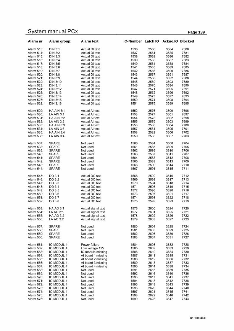
System manual PCx Page 139
81300046D
Alarm nr Alarm group: Alarm text: IO-Number Latch IO Ackno.IO Blocked Alarm 513: DIN 3:1 Actual DI text 1536 2560 3584 7680 Alarm 514: DIN 3:2 Actual DI text 1537 2561 3585 7681 Alarm 515: DIN 3:3 Actual DI text 1538 2562 3586 7682 Alarm 516: DIN 3:4 Actual DI text 1539 2563 3587 7683 Alarm 517: DIN 3:5 Actual DI text 1540 2564 3588 7684 Alarm 518: DIN 3:6 Actual DI text 1541 2565 3589 7685 Alarm 519: DIN 3:7 Actual DI text 1542 2566 3590 7686 Alarm 520: DIN 3:8 Actual DI text 1543 2567 3591 7687 Alarm 521: DIN 3:9 Actual DI text 1544 2568 3592 7688 Alarm 522: DIN 3:10 Actual DI text 1545 2569 3593 7689 Alarm 523: DIN 3:11 Actual DI text 1546 2570 3594 7690 Alarm 524: DIN 3:12 Actual DI text 1547 2571 3595 7691 Alarm 525: DIN 3:13 Actual DI text 1548 2572 3596 7692 Alarm 526: DIN 3:14 Actual DI text 1549 2573 3597 7693 Alarm 527: DIN 3:15 Actual DI text 1550 2574 3598 7694 Alarm 528: DIN 3:16 Actual DI text 1551 2575 3599 7695 Alarm 529: HA AIN 3:1 Actual AI text 1552 2576 3600 7696 Alarm 530: LA AIN 3:1 Actual AI text 1553 2577 3601 7697 Alarm 531: HA AIN 3:2 Actual AI text 1554 2578 3602 7698 Alarm 532: LA AIN 3:2 Actual AI text 1555 2579 3603 7699 Alarm 533: HA AIN 3:3 Actual AI text 1556 2580 3604 7700 Alarm 534: LA AIN 3:3 Actual AI text 1557 2581 3605 7701 Alarm 535: HA AIN 3:4 Actual AI text 1558 2582 3606 7702 Alarm 536: LA AIN 3:4 Actual AI text 1559 2583 3607 7703 Alarm 537: SPARE Not used 1560 2584 3608 7704 Alarm 538: SPARE Not used 1561 2585 3609 7705 Alarm 539: SPARE Not used 1562 2586 3610 7706 Alarm 540: SPARE Not used 1563 2587 3611 7707 Alarm 541: SPARE Not used 1564 2588 3612 7708 Alarm 542: SPARE Not used 1565 2589 3613 7709 Alarm 543: SPARE Not used 1566 2590 3614 7710 Alarm 544: SPARE Not used 1567 2591 3615 7711 Alarm 545: DO 3:1 Actual DO text 1568 2592 3616 7712 Alarm 546: DO 3:2 Actual DO text 1569 2593 3617 7713 Alarm 547: DO 3:3 Actual DO text 1570 2594 3618 7714 Alarm 548: DO 3:4 Actual DO text 1571 2595 3619 7715 Alarm 549: DO 3:5 Actual DO text 1572 2596 3620 7716 Alarm 550: DO 3:6 Actual DO text 1573 2597 3621 7717 Alarm 551: DO 3:7 Actual DO text 1574 2598 3622 7718 Alarm 552: DO 3:8 Actual DO text 1575 2599 3623 7719 Alarm 553: HA AO 3:1 Actual signal text 1576 2600 3624 7720 Alarm 554: LA AO 3:1 Actual signal text 1577 2601 3625 7721 Alarm 555: HA AO 3:2 Actual signal text 1578 2602 3626 7722 Alarm 556: LA AO 3:2 Actual signal text 1579 2603 3627 7723 Alarm 557: SPARE Not used 1580 2604 3628 7724 Alarm 558: SPARE Not used 1581 2605 3629 7725 Alarm 559: SPARE Not used 1582 2606 3630 7726 Alarm 560: SPARE Not used 1583 2607 3631 7727 Alarm 561: IO MODUL 4 Power failure 1584 2608 3632 7728 Alarm 562: IO MODUL 4 Low voltage 12V 1585 2609 3633 7729 Alarm 563: IO MODUL 4 IO module missing 1586 2610 3634 7730 Alarm 564: IO MODUL 4 AI board 1 missing 1587 2611 3635 7731 Alarm 565: IO MODUL 4 AI board 2 missing 1588 2612 3636 7732 Alarm 566: IO MODUL 4 AI board 3 missing 1589 2613 3637 7733 Alarm 567: IO MODUL 4 AI board 4 missing 1590 2614 3638 7734 Alarm 568: IO MODUL 4 Not used 1591 2615 3639 7735 Alarm 569: IO MODUL 4 Not used 1592 2616 3640 7736 Alarm 570: IO MODUL 4 Not used 1593 2617 3641 7737 Alarm 571: IO MODUL 4 Not used 1594 2618 3642 7738 Alarm 572: IO MODUL 4 Not used 1595 2619 3643 7739 Alarm 573: IO MODUL 4 Not used 1596 2620 3644 7740 Alarm 574: IO MODUL 4 Not used 1597 2621 3645 7741 Alarm 575: IO MODUL 4 Not used 1598 2622 3646 7742 Alarm 576: IO MODUL 4 Not used 1599 2623 3647 7743

System manual PCx Page 140
81300046D
Alarm nr Alarm group: Alarm text: IO-Number Latch IO Ackno.IO Blocked Alarm 577: DIN 4:1 Actual DI text 1600 2624 3648 7744 Alarm 578: DIN 4:2 Actual DI text 1601 2625 3649 7745 Alarm 579: DIN 4:3 Actual DI text 1602 2626 3650 7746 Alarm 580: DIN 4:4 Actual DI text 1603 2627 3651 7747 Alarm 581: DIN 4:5 Actual DI text 1604 2628 3652 7748 Alarm 582: DIN 4:6 Actual DI text 1605 2629 3653 7749 Alarm 583: DIN 4:7 Actual DI text 1606 2630 3654 7750 Alarm 584: DIN 4:8 Actual DI text 1607 2631 3655 7751 Alarm 585: DIN 4:9 Actual DI text 1608 2632 3656 7752 Alarm 586: DIN 4:10 Actual DI text 1609 2633 3657 7753 Alarm 587: DIN 4:11 Actual DI text 1610 2634 3658 7754 Alarm 588: DIN 4:12 Actual DI text 1611 2635 3659 7755 Alarm 589: DIN 4:13 Actual DI text 1612 2636 3660 7756 Alarm 590: DIN 4:14 Actual DI text 1613 2637 3661 7757 Alarm 591: DIN 4:15 Actual DI text 1614 2638 3662 7758 Alarm 592: DIN 4:16 Actual DI text 1615 2639 3663 7759 Alarm 593: HA AIN 4:1 Actual AI text 1616 2640 3664 7760 Alarm 594: LA AIN 4:1 Actual AI text 1617 2641 3665 7761 Alarm 595: HA AIN 4:2 Actual AI text 1618 2642 3666 7762 Alarm 596: LA AIN 4:2 Actual AI text 1619 2643 3667 7763 Alarm 597: HA AIN 4:3 Actual AI text 1620 2644 3668 7764 Alarm 598: LA AIN 4:3 Actual AI text 1621 2645 3669 7765 Alarm 599: HA AIN 4:4 Actual AI text 1622 2646 3670 7766 Alarm 600: LA AIN 4:4 Actual AI text 1623 2647 3671 7767 Alarm 601: SPARE Not used 1624 2648 3672 7768 Alarm 602: SPARE Not used 1625 2649 3673 7769 Alarm 603: SPARE Not used 1626 2650 3674 7770 Alarm 604: SPARE Not used 1627 2651 3675 7771 Alarm 605: SPARE Not used 1628 2652 3676 7772 Alarm 606: SPARE Not used 1629 2653 3677 7773 Alarm 607: SPARE Not used 1630 2654 3678 7774 Alarm 608: SPARE Not used 1631 2655 3679 7775 Alarm 609: DO 4:1 Actual DO text 1632 2656 3680 7776 Alarm 610: DO 4:2 Actual DO text 1633 2657 3681 7777 Alarm 611: DO 4:3 Actual DO text 1634 2658 3682 7778 Alarm 612: DO 4:4 Actual DO text 1635 2659 3683 7779 Alarm 613: DO 4:5 Actual DO text 1636 2660 3684 7780 Alarm 614: DO 4:6 Actual DO text 1637 2661 3685 7781 Alarm 615: DO 4:7 Actual DO text 1638 2662 3686 7782 Alarm 616: DO 4:8 Actual DO text 1639 2663 3687 7783 Alarm 617: HA AO 4:1 Actual signal text 1640 2664 3688 7784 Alarm 618: LA AO 4:1 Actual signal text 1641 2665 3689 7785 Alarm 619: HA AO 4:2 Actual signal text 1642 2666 3690 7786 Alarm 620: LA AO 4:2 Actual signal text 1643 2667 3691 7787 Alarm 621: SPARE Not used 1644 2668 3692 7788 Alarm 622: SPARE Not used 1645 2669 3693 7789 Alarm 623: SPARE Not used 1646 2670 3694 7790 Alarm 624: SPARE Not used 1647 2671 3695 7791 Alarm 625: IO MODUL 5 Power failure 1648 2672 3696 7792 Alarm 626: IO MODUL 5 Low voltage 12V 1649 2673 3697 7793 Alarm 627: IO MODUL 5 IO module missing 1650 2674 3698 7794 Alarm 628: IO MODUL 5 AI board 1 missing 1651 2675 3699 7795 Alarm 629: IO MODUL 5 AI board 2 missing 1652 2676 3700 7796 Alarm 630: IO MODUL 5 AI board 3 missing 1653 2677 3701 7797 Alarm 631: IO MODUL 5 AI board 4 missing 1654 2678 3702 7798 Alarm 632: IO MODUL 5 Not used 1655 2679 3703 7799 Alarm 633: IO MODUL 5 Not used 1656 2680 3704 7800 Alarm 634: IO MODUL 5 Not used 1657 2681 3705 7801 Alarm 635: IO MODUL 5 Not used 1658 2682 3706 7802 Alarm 636: IO MODUL 5 Not used 1659 2683 3707 7803 Alarm 637: IO MODUL 5 Not used 1660 2684 3708 7804 Alarm 638: IO MODUL 5 Not used 1661 2685 3709 7805 Alarm 639: IO MODUL 5 Not used 1662 2686 3710 7806 Alarm 640: IO MODUL 5 Not used 1663 2687 3711 7807

System manual PCx Page 141
81300046D
Alarm nr Alarm group: Alarm text: IO-Number Latch IO Ackno.IO Blocked Alarm 641: DIN 5:1 Actual DI text 1664 2688 3712 7808 Alarm 642: DIN 5:2 Actual DI text 1665 2689 3713 7809 Alarm 643: DIN 5:3 Actual DI text 1666 2690 3714 7810 Alarm 644: DIN 5:4 Actual DI text 1667 2691 3715 7811 Alarm 645: DIN 5:5 Actual DI text 1668 2692 3716 7812 Alarm 646: DIN 5:6 Actual DI text 1669 2693 3717 7813 Alarm 647: DIN 5:7 Actual DI text 1670 2694 3718 7814 Alarm 648: DIN 5:8 Actual DI text 1671 2695 3719 7815 Alarm 649: DIN 5:9 Actual DI text 1672 2696 3720 7816 Alarm 650: DIN 5:10 Actual DI text 1673 2697 3721 7817 Alarm 651: DIN 5:11 Actual DI text 1674 2698 3722 7818 Alarm 652: DIN 5:12 Actual DI text 1675 2699 3723 7819 Alarm 653: DIN 5:13 Actual DI text 1676 2700 3724 7820 Alarm 654: DIN 5:14 Actual DI text 1677 2701 3725 7821 Alarm 655: DIN 5:15 Actual DI text 1678 2702 3726 7822 Alarm 656: DIN 5:16 Actual DI text 1679 2703 3727 7823 Alarm 657: HA AIN 5:1 Actual AI text 1680 2704 3728 7824 Alarm 658: LA AIN 5:1 Actual AI text 1681 2705 3729 7825 Alarm 659: HA AIN 5:2 Actual AI text 1682 2706 3730 7826 Alarm 660: LA AIN 5:2 Actual AI text 1683 2707 3731 7827 Alarm 661: HA AIN 5:3 Actual AI text 1684 2708 3732 7828 Alarm 662: LA AIN 5:3 Actual AI text 1685 2709 3733 7829 Alarm 663: HA AIN 5:4 Actual AI text 1686 2710 3734 7830 Alarm 664: LA AIN 5:4 Actual AI text 1687 2711 3735 7831 Alarm 665: SPARE Not used 1688 2712 3736 7832 Alarm 666: SPARE Not used 1689 2713 3737 7833 Alarm 667: SPARE Not used 1690 2714 3738 7834 Alarm 668: SPARE Not used 1691 2715 3739 7835 Alarm 669: SPARE Not used 1692 2716 3740 7836 Alarm 670: SPARE Not used 1693 2717 3741 7837 Alarm 671: SPARE Not used 1694 2718 3742 7838 Alarm 672: SPARE Not used 1695 2719 3743 7839 Alarm 673: DO 5:1 Actual DO text 1696 2720 3744 7840 Alarm 674: DO 5:2 Actual DO text 1697 2721 3745 7841 Alarm 675: DO 5:3 Actual DO text 1698 2722 3746 7842 Alarm 676: DO 5:4 Actual DO text 1699 2723 3747 7843 Alarm 677: DO 5:5 Actual DO text 1700 2724 3748 7844 Alarm 678: DO 5:6 Actual DO text 1701 2725 3749 7845 Alarm 679: DO 5:7 Actual DO text 1702 2726 3750 7846 Alarm 680: DO 5:8 Actual DO text 1703 2727 3751 7847 Alarm 681: HA AO 5:1 Actual signal text 1704 2728 3752 7848 Alarm 682: LA AO 5:1 Actual signal text 1705 2729 3753 7849 Alarm 683: HA AO 5:2 Actual signal text 1706 2730 3754 7850 Alarm 684: LA AO 5:2 Actual signal text 1707 2731 3755 7851 Alarm 685: SPARE Not used 1708 2732 3756 7852 Alarm 686: SPARE Not used 1709 2733 3757 7853 Alarm 687: SPARE Not used 1710 2734 3758 7854 Alarm 688: SPARE Not used 1711 2735 3759 7855 Alarm 689: IO MODUL 6 Power failure 1712 2736 3760 7856 Alarm 690: IO MODUL 6 Low voltage 12V 1713 2737 3761 7857 Alarm 691: IO MODUL 6 IO module missing 1714 2738 3762 7858 Alarm 692: IO MODUL 6 AI board 1 missing 1715 2739 3763 7859 Alarm 693: IO MODUL 6 AI board 2 missing 1716 2740 3764 7860 Alarm 694: IO MODUL 6 AI board 3 missing 1717 2741 3765 7861 Alarm 695: IO MODUL 6 AI board 4 missing 1718 2742 3766 7862 Alarm 696: IO MODUL 6 Not used 1719 2743 3767 7863 Alarm 697: IO MODUL 6 Not used 1720 2744 3768 7864 Alarm 698: IO MODUL 6 Not used 1721 2745 3769 7865 Alarm 699: IO MODUL 6 Not used 1722 2746 3770 7866 Alarm 700: IO MODUL 6 Not used 1723 2747 3771 7867 Alarm 701: IO MODUL 6 Not used 1724 2748 3772 7868 Alarm 702: IO MODUL 6 Not used 1725 2749 3773 7869 Alarm 703: IO MODUL 6 Not used 1726 2750 3774 7870 Alarm 704: IO MODUL 6 Not used 1727 2751 3775 7871

System manual PCx Page 142
81300046D
Alarm nr Alarm group: Alarm text: IO-Number Latch IO Ackno.IO Blocked Alarm 705: DIN 6:1 Actual DI text 1728 2752 3776 7872 Alarm 706: DIN 6:2 Actual DI text 1729 2753 3777 7873 Alarm 707: DIN 6:3 Actual DI text 1730 2754 3778 7874 Alarm 708: DIN 6:4 Actual DI text 1731 2755 3779 7875 Alarm 709: DIN 6:5 Actual DI text 1732 2756 3780 7876 Alarm 710: DIN 6:6 Actual DI text 1733 2757 3781 7877 Alarm 711: DIN 6:7 Actual DI text 1734 2758 3782 7878 Alarm 712: DIN 6:8 Actual DI text 1735 2759 3783 7879 Alarm 713: DIN 6:9 Actual DI text 1736 2760 3784 7880 Alarm 714: DIN 6:10 Actual DI text 1737 2761 3785 7881 Alarm 715: DIN 6:11 Actual DI text 1738 2762 3786 7882 Alarm 716: DIN 6:12 Actual DI text 1739 2763 3787 7883 Alarm 717: DIN 6:13 Actual DI text 1740 2764 3788 7884 Alarm 718: DIN 6:14 Actual DI text 1741 2765 3789 7885 Alarm 719: DIN 6:15 Actual DI text 1742 2766 3790 7886 Alarm 720: DIN 6:16 Actual DI text 1743 2767 3791 7887 Alarm 721: HA AIN 6:1 Actual AI text 1744 2768 3792 7888 Alarm 722: LA AIN 6:1 Actual AI text 1745 2769 3793 7889 Alarm 723: HA AIN 6:2 Actual AI text 1746 2770 3794 7890 Alarm 724: LA AIN 6:2 Actual AI text 1747 2771 3795 7891 Alarm 725: HA AIN 6:3 Actual AI text 1748 2772 3796 7892 Alarm 726: LA AIN 6:3 Actual AI text 1749 2773 3797 7893 Alarm 727: HA AIN 6:4 Actual AI text 1750 2774 3798 7894 Alarm 728: LA AIN 6:4 Actual AI text 1751 2775 3799 7895 Alarm 729: SPARE Not used 1752 2776 3800 7896 Alarm 730: SPARE Not used 1753 2777 3801 7897 Alarm 731: SPARE Not used 1754 2778 3802 7898 Alarm 732: SPARE Not used 1755 2779 3803 7899 Alarm 733: SPARE Not used 1756 2780 3804 7900 Alarm 734: SPARE Not used 1757 2781 3805 7901 Alarm 735: SPARE Not used 1758 2782 3806 7902 Alarm 736: SPARE Not used 1759 2783 3807 7903 Alarm 737: DO 6:1 Actual DO text 1760 2784 3808 7904 Alarm 738: DO 6:2 Actual DO text 1761 2785 3809 7905 Alarm 739: DO 6:3 Actual DO text 1762 2786 3810 7906 Alarm 740: DO 6:4 Actual DO text 1763 2787 3811 7907 Alarm 741: DO 6:5 Actual DO text 1764 2788 3812 7908 Alarm 742: DO 6:6 Actual DO text 1765 2789 3813 7909 Alarm 743: DO 6:7 Actual DO text 1766 2790 3814 7910 Alarm 744: DO 6:8 Actual DO text 1767 2791 3815 7911 Alarm 745: HA AO 6:1 Actual signal text 1768 2792 3816 7912 Alarm 746: LA AO 6:1 Actual signal text 1769 2793 3817 7913 Alarm 747: HA AO 6:2 Actual signal text 1770 2794 3818 7914 Alarm 748: LA AO 6:2 Actual signal text 1771 2795 3819 7915 Alarm 749: SPARE Not used 1772 2796 3820 7916 Alarm 750: SPARE Not used 1773 2797 3821 7917 Alarm 751: SPARE Not used 1774 2798 3822 7918 Alarm 752: SPARE Not used 1775 2799 3823 7919 Alarm 753: IO MODUL 7 Power failure 1776 2800 3824 7920 Alarm 754: IO MODUL 7 Low voltage 12V 1777 2801 3825 7921 Alarm 755: IO MODUL 7 IO module missing 1778 2802 3826 7922 Alarm 756: IO MODUL 7 AI board 1 missing 1779 2803 3827 7923 Alarm 757: IO MODUL 7 AI board 2 missing 1780 2804 3828 7924 Alarm 758: IO MODUL 7 AI board 3 missing 1781 2805 3829 7925 Alarm 759: IO MODUL 7 AI board 4 missing 1782 2806 3830 7926 Alarm 760: IO MODUL 7 Not used 1783 2807 3831 7927 Alarm 761: IO MODUL 7 Not used 1784 2808 3832 7928 Alarm 762: IO MODUL 7 Not used 1785 2809 3833 7929 Alarm 763: IO MODUL 7 Not used 1786 2810 3834 7930 Alarm 764: IO MODUL 7 Not used 1787 2811 3835 7931 Alarm 765: IO MODUL 7 Not used 1788 2812 3836 7932 Alarm 766: IO MODUL 7 Not used 1789 2813 3837 7933 Alarm 767: IO MODUL 7 Not used 1790 2814 3838 7934 Alarm 768: IO MODUL 7 Not used 1791 2815 3839 7935

System manual PCx Page 143
81300046D
Alarm nr Alarm group: Alarm text: IO-Number Latch IO Ackno.IO Blocked Alarm 769: DIN 7:1 Actual DI text 1792 2816 3840 7936 Alarm 770: DIN 7:2 Actual DI text 1793 2817 3841 7937 Alarm 771: DIN 7:3 Actual DI text 1794 2818 3842 7938 Alarm 772: DIN 7:4 Actual DI text 1795 2819 3843 7939 Alarm 773: DIN 7:5 Actual DI text 1796 2820 3844 7940 Alarm 774: DIN 7:6 Actual DI text 1797 2821 3845 7941 Alarm 775: DIN 7:7 Actual DI text 1798 2822 3846 7942 Alarm 776: DIN 7:8 Actual DI text 1799 2823 3847 7943 Alarm 777: DIN 7:9 Actual DI text 1800 2824 3848 7944 Alarm 778: DIN 7:10 Actual DI text 1801 2825 3849 7945 Alarm 779: DIN 7:11 Actual DI text 1802 2826 3850 7946 Alarm 780: DIN 7:12 Actual DI text 1803 2827 3851 7947 Alarm 781: DIN 7:13 Actual DI text 1804 2828 3852 7948 Alarm 782: DIN 7:14 Actual DI text 1805 2829 3853 7949 Alarm 783: DIN 7:15 Actual DI text 1806 2830 3854 7950 Alarm 784: DIN 7:16 Actual DI text 1807 2831 3855 7951 Alarm 785: HA AIN 7:1 Actual AI text 1808 2832 3856 7952 Alarm 786: LA AIN 7:1 Actual AI text 1809 2833 3857 7953 Alarm 787: HA AIN 7:2 Actual AI text 1810 2834 3858 7954 Alarm 788: LA AIN 7:2 Actual AI text 1811 2835 3859 7955 Alarm 789: HA AIN 7:3 Actual AI text 1812 2836 3860 7956 Alarm 790: LA AIN 7:3 Actual AI text 1813 2837 3861 7957 Alarm 791: HA AIN 7:4 Actual AI text 1814 2838 3862 7958 Alarm 792: LA AIN 7:4 Actual AI text 1815 2839 3863 7959 Alarm 793: SPARE Not used 1816 2840 3864 7960 Alarm 794: SPARE Not used 1817 2841 3865 7961 Alarm 795: SPARE Not used 1818 2842 3866 7962 Alarm 796: SPARE Not used 1819 2843 3867 7963 Alarm 797: SPARE Not used 1820 2844 3868 7964 Alarm 798: SPARE Not used 1821 2845 3869 7965 Alarm 799: SPARE Not used 1822 2846 3870 7966 Alarm 800: SPARE Not used 1823 2847 3871 7967 Alarm 801: DO 7:1 Actual DO text 1824 2848 3872 7968 Alarm 802: DO 7:2 Actual DO text 1825 2849 3873 7969 Alarm 803: DO 7:3 Actual DO text 1826 2850 3874 7970 Alarm 804: DO 7:4 Actual DO text 1827 2851 3875 7971 Alarm 805: DO 7:5 Actual DO text 1828 2852 3876 7972 Alarm 806: DO 7:6 Actual DO text 1829 2853 3877 7973 Alarm 807: DO 7:7 Actual DO text 1830 2854 3878 7974 Alarm 808: DO 7:8 Actual DO text 1831 2855 3879 7975 Alarm 809: HA AO 7:1 Actual signal text 1832 2856 3880 7976 Alarm 810: LA AO 7:1 Actual signal text 1833 2857 3881 7977 Alarm 811: HA AO 7:2 Actual signal text 1834 2858 3882 7978 Alarm 812: LA AO 7:2 Actual signal text 1835 2859 3883 7979 Alarm 813: SPARE Not used 1836 2860 3884 7980 Alarm 814: SPARE Not used 1837 2861 3885 7981 Alarm 815: SPARE Not used 1838 2862 3886 7982 Alarm 816: SPARE Not used 1839 2863 3887 7983 Alarm 817: IO MODUL 8 Power failure 1840 2864 3888 7984 Alarm 818: IO MODUL 8 Low voltage 12V 1841 2865 3889 7985 Alarm 819: IO MODUL 8 IO module missing 1842 2866 3890 7986 Alarm 820: IO MODUL 8 AI board 1 missing 1843 2867 3891 7987 Alarm 821: IO MODUL 8 AI board 2 missing 1844 2868 3892 7988 Alarm 822: IO MODUL 8 AI board 3 missing 1845 2869 3893 7989 Alarm 823: IO MODUL 8 AI board 4 missing 1846 2870 3894 7990 Alarm 824: IO MODUL 8 Not used 1847 2871 3895 7991 Alarm 825: IO MODUL 8 Not used 1848 2872 3896 7992 Alarm 826: IO MODUL 8 Not used 1849 2873 3897 7993 Alarm 827: IO MODUL 8 Not used 1850 2874 3898 7994 Alarm 828: IO MODUL 8 Not used 1851 2875 3899 7995 Alarm 829: IO MODUL 8 Not used 1852 2876 3900 7996 Alarm 830: IO MODUL 8 Not used 1853 2877 3901 7997 Alarm 831: IO MODUL 8 Not used 1854 2878 3902 7998 Alarm 832: IO MODUL 8 Not used 1855 2879 3903 7999
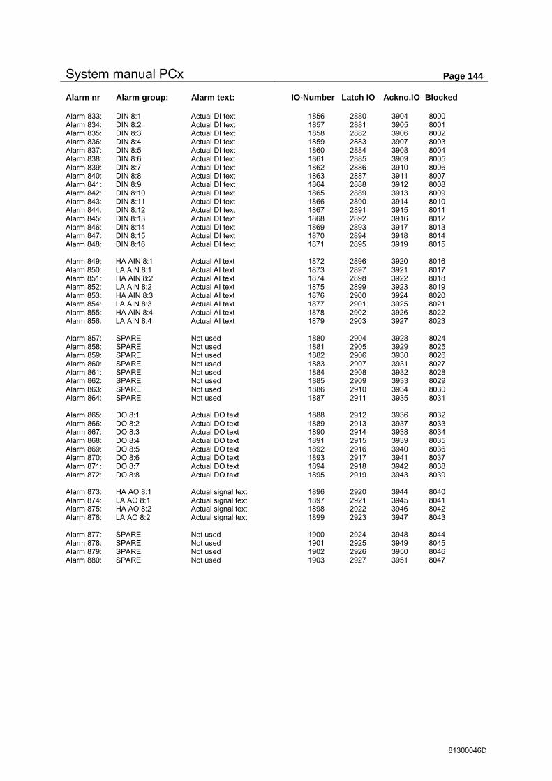
System manual PCx Page 144
81300046D
Alarm nr Alarm group: Alarm text: IO-Number Latch IO Ackno.IO Blocked Alarm 833: DIN 8:1 Actual DI text 1856 2880 3904 8000 Alarm 834: DIN 8:2 Actual DI text 1857 2881 3905 8001 Alarm 835: DIN 8:3 Actual DI text 1858 2882 3906 8002 Alarm 836: DIN 8:4 Actual DI text 1859 2883 3907 8003 Alarm 837: DIN 8:5 Actual DI text 1860 2884 3908 8004 Alarm 838: DIN 8:6 Actual DI text 1861 2885 3909 8005 Alarm 839: DIN 8:7 Actual DI text 1862 2886 3910 8006 Alarm 840: DIN 8:8 Actual DI text 1863 2887 3911 8007 Alarm 841: DIN 8:9 Actual DI text 1864 2888 3912 8008 Alarm 842: DIN 8:10 Actual DI text 1865 2889 3913 8009 Alarm 843: DIN 8:11 Actual DI text 1866 2890 3914 8010 Alarm 844: DIN 8:12 Actual DI text 1867 2891 3915 8011 Alarm 845: DIN 8:13 Actual DI text 1868 2892 3916 8012 Alarm 846: DIN 8:14 Actual DI text 1869 2893 3917 8013 Alarm 847: DIN 8:15 Actual DI text 1870 2894 3918 8014 Alarm 848: DIN 8:16 Actual DI text 1871 2895 3919 8015 Alarm 849: HA AIN 8:1 Actual AI text 1872 2896 3920 8016 Alarm 850: LA AIN 8:1 Actual AI text 1873 2897 3921 8017 Alarm 851: HA AIN 8:2 Actual AI text 1874 2898 3922 8018 Alarm 852: LA AIN 8:2 Actual AI text 1875 2899 3923 8019 Alarm 853: HA AIN 8:3 Actual AI text 1876 2900 3924 8020 Alarm 854: LA AIN 8:3 Actual AI text 1877 2901 3925 8021 Alarm 855: HA AIN 8:4 Actual AI text 1878 2902 3926 8022 Alarm 856: LA AIN 8:4 Actual AI text 1879 2903 3927 8023 Alarm 857: SPARE Not used 1880 2904 3928 8024 Alarm 858: SPARE Not used 1881 2905 3929 8025 Alarm 859: SPARE Not used 1882 2906 3930 8026 Alarm 860: SPARE Not used 1883 2907 3931 8027 Alarm 861: SPARE Not used 1884 2908 3932 8028 Alarm 862: SPARE Not used 1885 2909 3933 8029 Alarm 863: SPARE Not used 1886 2910 3934 8030 Alarm 864: SPARE Not used 1887 2911 3935 8031 Alarm 865: DO 8:1 Actual DO text 1888 2912 3936 8032 Alarm 866: DO 8:2 Actual DO text 1889 2913 3937 8033 Alarm 867: DO 8:3 Actual DO text 1890 2914 3938 8034 Alarm 868: DO 8:4 Actual DO text 1891 2915 3939 8035 Alarm 869: DO 8:5 Actual DO text 1892 2916 3940 8036 Alarm 870: DO 8:6 Actual DO text 1893 2917 3941 8037 Alarm 871: DO 8:7 Actual DO text 1894 2918 3942 8038 Alarm 872: DO 8:8 Actual DO text 1895 2919 3943 8039 Alarm 873: HA AO 8:1 Actual signal text 1896 2920 3944 8040 Alarm 874: LA AO 8:1 Actual signal text 1897 2921 3945 8041 Alarm 875: HA AO 8:2 Actual signal text 1898 2922 3946 8042 Alarm 876: LA AO 8:2 Actual signal text 1899 2923 3947 8043 Alarm 877: SPARE Not used 1900 2924 3948 8044 Alarm 878: SPARE Not used 1901 2925 3949 8045 Alarm 879: SPARE Not used 1902 2926 3950 8046 Alarm 880: SPARE Not used 1903 2927 3951 8047

System manual PCx Page 145
81300046D
10 Index
A
Alarm dial ................................................................... 100 Alarm numbers ............................................................ 131 Alarm Show / Program .................................................. 50 Alarmhandling............................................................... 33 Analogue history ..................................................... 32, 93 Analogue in ................................................................... 70 Analogue input types ..................................................... 71 Analogue out ................................................................. 78
B
Back - up control ........................................................... 10 Back-up start ................................................................. 47
C
Channel flow ................................................................. 81 Comli/Modbus master ................................................... 30 Communication ............................................................. 98 Configuration .................................................................. 8
D
Data security ................................................................... 5 Date ............................................................................... 91 Datum ...................................................................... 88, 91 Digital history................................................................ 93 Digital in ....................................................................... 54 Digital input types ......................................................... 55 Digital out ..................................................................... 62 Digital output types ....................................................... 63
F
Flow/pulse menu ........................................................... 80 Function codes .............................................................. 88
H
High level float ........................................................ 47, 55 Huvudmeny ................................................................... 87
I
Index ........................................................................... 145 IO-number list ............................................................. 127
K
Keyboard description ...................................................... 6
L
LED -alarmindication ................................................... 33 LED configuration ........................................................ 92 Level sensor .................................................................. 72
M
Main menu .................................................................... 86 Manual pump control .................................................... 83 Manual start .................................................................. 11 Modem and alarm call .................................................. 34 Motor current .......................................................... 43, 71 Motor protector ....................................................... 43, 56
O
Overflow ........................................................... 48, 55, 73 Overflow flow measuring ............................................. 22
P
Palmer Bowlus flume .................................................... 20 Parshall and Venturi flume ........................................... 19 Person alarm ................................................................. 57 PID controller ......................................................... 28, 84 Pit shape ........................................................................ 15 Program functions ......................................................... 10 Program structure ............................................................ 4 Program version .......................................................... 125 Pulse input .................................................................... 57 Pump ............................................................................. 63 Pump capacity ......................................................... 40, 42 Pump control ................................................................. 40 Pump curve ............................................................. 16, 42 Pump menu ................................................................... 40 Pump valve ............................................................. 13, 43 Pumpcapacity and In/Outflow....................................... 14 Pumpcontrol .................................................................. 10 Pumped volume ............................................................ 45 Pumppit menu ............................................................... 45 Pumppit valve ......................................................... 13, 48 Pumpreversing .............................................................. 11
R
Remote communication .............................................. 103 Remote control .............................................................. 30 Reset motor protector .................................................... 11 Reset motors protector .................................................. 65

System manual PCx Page 146
81300046D
Reverse pump .......................................................... 42, 65 Running indication .................................................. 11, 42
S
Sedimentation pit .......................................................... 95 Sequence control ........................................................... 92 Shift motor ........................................................ 30, 67, 97 Speed control of pumps ................................................. 24 Spray ............................................................................. 65 Spray pumppit ............................................................... 12 Standard configuration ................................................ 105 Start confirmation .......................................................... 56 Station identity ............................................................ 101 Straight weir .................................................................. 17 Straight weir without and with contraction ................... 81
T
Text writing .................................................................... 7 Tid ................................................................................. 91 Time .............................................................................. 91 Timer ...................................................................... 67, 91 Trig of master communcation ....................................... 31
V,W
V-notch weir ................................................................. 18

Sulzer Pump Solutions Ireland Ltd., Clonard Road, Wexford, IrelandTel. +353 53 91 63 200, Fax +353 53 91 42 335, www.sulzer.com
2014 Copyright © Sulzer