Embed Size (px)
Citation preview

Controller for appliance controlAK-CC 550
Manual

2 Manual RS8EN302 © Danfoss 10-2008 AK-CC 550
IntroductionApplicationComplete refrigeration appliance control with great flexibility to adapt to all types of refrigeration appliances and cold storage rooms.
Advantages• Energyoptimisationofthewholerefrigerationappliance•Onecontrollerforseveraldifferentrefrigerationappliances• Integrateddisplayatthefrontofthecontroller•Quickset-upwithpredefinedsettings• Built-indatacommunication• Built-inclockfunctionwithpowerreserve
PrincipleThe temperature in the appliance is registered by one or two temperature sensors which are located in the air flow before the evaporator(S3)oraftertheevaporator(S4)respectively.Asettingfor thermostat, alarm thermostat and display reading determines theinfluencethetwosensorvaluesshouldhaveforeachindi-vidualfunction.InadditionproductsensorS6,whichcanbeoptionallyplacedinthe appliance, can be used to register the temperature near the required product in a certain place within the appliance. ThetemperatureoftheevaporatorisregisteredwiththeS5sensorwhich can be used as a defrosting sensor.InadditiontotheoutlettotheelectronicinjectionvalveofthetypeAKV,thecontrollerhas5relayoutputswhicharedefinedbytheuseselected–theindividualusageoptionsaredescribedindetail on page 12.
Functions•Day/nightthermostatwithON/OFFormodulatingprinciple• ProductsensorS6withseparatealarmlimits• Switchbetweenthermostatsettingsviadigitalinput• Adaptivecontrolofsuperheat• Adaptivedefrostingbasedonevaporatorperformance• Startofdefrostviaschedule,digitalinputornetwork•Natural,electricorhotgasdefrost• Stopofdefrostontimeand/ortemperature• Coordinationofdefrostingamongseveralcontrols• Pulsingoffanswhenthermostatissatisfied• CasecleaningfunctionfordocumentationofHACCPprocedure• Railheatcontrolviaday/nightloadordewpoint•Doorfunction• Controloftwocompressors• Controlofnightblinds• Lightcontrol•Heatthermostat• Factorycalibrationthatwillguaranteeabettermeasuringaccu-racythanstatedinthestandardEN441-13withoutsubsequentcalibration(Pt1000ohmsensor)
• IntegratedMODBUScommunicationwiththeoptionofmount-ingaLonWorkscommunicationcard Appliance examples
ContentsIntroduction ....................................................................................................... 2Operation ............................................................................................................ 4Applications .....................................................................................................12Surveyoffunctions ........................................................................................15Operation ..........................................................................................................26Menusurvey .....................................................................................................28Connections .....................................................................................................32Data .....................................................................................................................34Ordering ............................................................................................................35
AK-CC 550 Manual RS8EN302 © Danfoss 10-2008 3
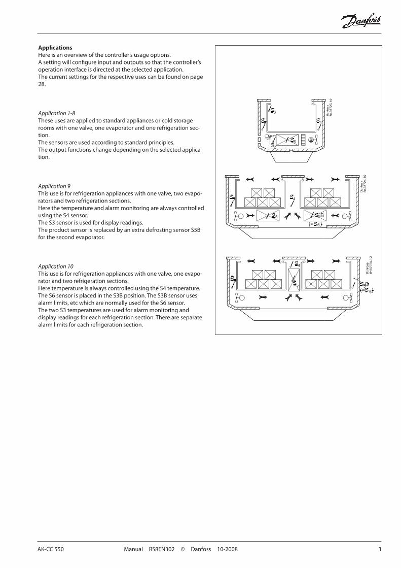
ApplicationsHereisanoverviewofthecontroller’susageoptions.Asettingwillconfigureinputandoutputssothatthecontroller’soperation interface is directed at the selected application.Thecurrentsettingsfortherespectiveusescanbefoundonpage28.
Application 1-8These uses are applied to standard appliances or cold storage roomswithonevalve,oneevaporatorandonerefrigerationsec-tion.The sensors are used according to standard principles.The output functions change depending on the selected applica-tion.
Application 9Thisuseisforrefrigerationapplianceswithonevalve,twoevapo-rators and two refrigeration sections.HerethetemperatureandalarmmonitoringarealwayscontrolledusingtheS4sensor.The S3 sensor is used for display readings. TheproductsensorisreplacedbyanextradefrostingsensorS5Bforthesecondevaporator.
Application 10Thisuseisforrefrigerationapplianceswithonevalve,oneevapo-rator and two refrigeration sections.HeretemperatureisalwayscontrolledusingtheS4temperature.TheS6sensorisplacedintheS3Bposition.TheS3Bsensorusesalarmlimits,etcwhicharenormallyusedfortheS6sensor.The two S3 temperatures are used for alarm monitoring and display readings for each refrigeration section. There are separate alarm limits for each refrigeration section.
4 Manual RS8EN302 © Danfoss 10-2008 AK-CC550
Operation
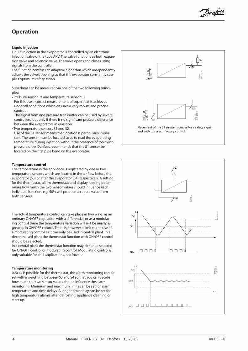
Liquid injection LiquidinjectionintheevaporatoriscontrolledbyanelectronicinjectionvalveofthetypeAKV.Thevalvefunctionsasbothexpan-sionvalveandsolenoidvalve.Thevalveopensandclosesusingsignals from the controller.Thefunctioncontainsanadaptivealgorithmwhichindependentlyadjuststhevalve’sopeningsothattheevaporatorconstantlysup-plies optimum refrigeration.
Superheatcanbemeasuredviaoneofthetwofollowingprinci-ples:•PressuresensorPeandtemperaturesensorS2Forthisuseacorrectmeasurementofsuperheatisachievedunderallconditionswhichensuresaveryrobustandprecisecontrol. Thesignalfromonepressuretransmittercanbeusedbyseveralcontrollers,butonlyifthereisnosignificantpressuredifferencebetweentheevaporatorsinquestion.
•TwotemperaturesensorsS1andS2UseoftheS1sensormeansthatlocationisparticularlyimpor-tant.Thesensormustbelocatedsoastoreadtheevaporatingtemperatureduringinjectionwithoutthepresenceoftoomuchpressure drop. Danfoss recommends that the S1 sensor be locatedonthefirstpipebendontheevaporator.
Temperature controlThe temperature in the appliance is registered by one or two temperature sensors which are located in the air flow before the evaporator(S3)oraftertheevaporator(S4)respectively.Asettingfor the thermostat, alarm thermostat and display reading deter-mineshowmuchthetwosensorvaluesshouldinfluenceeachindividualfunction,e.g.50%willproduceanequalvaluefromboth sensors.
Theactualtemperaturecontrolcantakeplaceintwoways:asanordinaryON/OFFregulationwithadifferential,orasamodulat-ingcontroltherethetemperaturevariationwillnotbenearlyasgreatasinON/OFFcontrol.Thereishoweveralimittotheuseofamodulatingcontrolasitcanonlybeusedincentralplant.InadecentralisedplantthethermostatfunctionwithON/OFFcontrolshould be selected.InacentralplantthethermostatfunctionmayeitherbeselectedforON/OFFcontrolormodulatingcontrol.Modulatingcontrolisonly suitable for chill applications, not frozen.
Temperature monitoringJust as is possible for the thermostat, the alarm monitoring can be setwithaweightingbetweenS3andS4sothatyoucandecidehowmuchthetwosensorvaluesshouldinfluencethealarmmonitoring. Minimum and maximum limits can be set for alarm temperature and time delays. A longer time delay can be set for high temperature alarms after defrosting, appliance cleaning or start-up.
PlacementoftheS1sensoriscrucialforasafetysignaland with this a satisfactory control.

AK-CC 550 Manual RS8EN302 © Danfoss 10-2008 5
Thermostat bandsThermostatbandscanbeusedbeneficiallyforapplianceswheredifferentproducttypesarestoredwhichrequiredifferenttem-peratureconditions.Itispossibletochangebetweenthetwodif-ferentthermostatbandsviaacontactsignalonadigitalinput.Onactivationthedisplaybrieflyshowswhichthermostatbandyouarechangingto.Thenthetemperaturevalueisdisplayed.Separate thermostat and alarm limits can be set for each thermo-stat band – also for the product sensor.
Night setback of thermostat valueInrefrigerationappliancestheremaybebigloaddifferencesbetweentheshop’sopeningandclosinghours,especiallyifnightlids/blindsareused.Thethermostatreferencemayberaisedherewithoutithavinganyeffectontheproducttemperature.Change-overbetweendayandnightoperationcantakeplace,asfollows:•viaanexternalswitchsignal.•viaasignalfromthedatacommunicationsystem.
Product sensorAseparateoptionalproductsensorS6,whichmaybeplacedin the appliance, can also be used and which can register and monitor the temperature in the warmest part of the appliance. There are separate alarm limits and time delays for the product sensor.
Appliance cleaningThisfunctionmakesiteasyfortheshop’sstafftocarryoutacleaning of the appliance according to a standard procedure.Appliancecleaningisactivatedviaasignal–asaruleviaakeyswitch placed on the appliance. Appliancecleaningiscarriedoutviathreephases:1-atthefirstactivationtherefrigerationisstopped,butthefans
keeponoperatinginordertodefrosttheevaporators.”Fan”isshown on the display.
2-atthesecondactivationthefansarealsostoppedandtheappliancecannowbecleaned.”OFF”isshownonthedisplay.
3-Atthethirdactivationrefrigerationisrecommenced.Thedisplay will show the actual appliance temperature.
Whenappliancecleaningisactivatedacleaningalarmistrans-mitted to the normal alarm recipient. A later processing of these alarms will document that the appliance has been cleaned as often as planned.
Alarm monitoringThere are no temperature alarms during appliance cleaning.
- + + °C
1 ÷ + Fan
2 ÷ ÷ Off
3 + + °C
6 Manual RS8EN302 © Danfoss 10-2008 AK-CC550
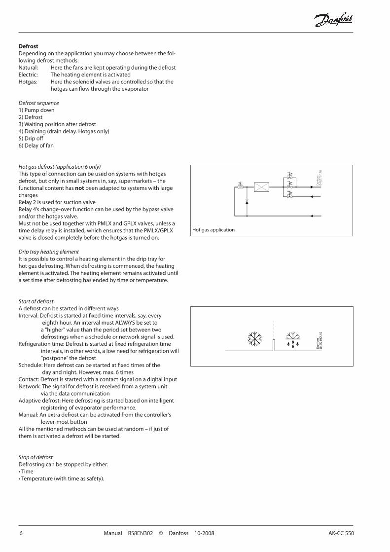
Hotgasapplication
DefrostDepending on the application you may choose between the fol-lowing defrost methods:Natural: HerethefansarekeptoperatingduringthedefrostElectric: TheheatingelementisactivatedHotgas: Herethesolenoidvalvesarecontrolledsothatthe hotgascanflowthroughtheevaporator
Defrost sequence1)Pumpdown2)Defrost3)Waitingpositionafterdefrost4)Draining(draindelay.Hotgasonly)5)Dripoff6)Delayoffan
Hot gas defrost (application 6 only)This type of connection can be used on systems with hotgas defrost,butonlyinsmallsystemsin,say,supermarkets–thefunctional content has not been adapted to systems with large chargesRelay2isusedforsuctionvalveRelay4’schange-overfunctioncanbeusedbythebypassvalveand/orthehotgasvalve.MustnotbeusedtogetherwithPMLXandGPLXvalves,unlessatimedelayrelayisinstalled,whichensuresthatthePMLX/GPLXvalveisclosedcompletelybeforethehotgasisturnedon.
Drip tray heating elementItispossibletocontrolaheatingelementinthedriptrayforhotgasdefrosting.Whendefrostingiscommenced,theheatingelementisactivated.Theheatingelementremainsactivateduntila set time after defrosting has ended by time or temperature.
Start of defrostAdefrostcanbestartedindifferentwaysInterval:Defrostisstartedatfixedtimeintervals,say,every
eighthhour.AnintervalmustALWAYSbesettoa"higher"valuethantheperiodsetbetweentwodefrostingswhenascheduleornetworksignalisused.
Refrigerationtime:Defrostisstartedatfixedrefrigerationtimeintervals,inotherwords,alowneedforrefrigerationwill”postpone”thedefrost
Schedule:Heredefrostcanbestartedatfixedtimesofthedayandnight.However,max.6times
Contact: Defrost is started with a contact signal on a digital inputNetwork:Thesignalfordefrostisreceivedfromasystemunit viathedatacommunicationAdaptivedefrost:Heredefrostingisstartedbasedonintelligent
registeringofevaporatorperformance.Manual:Anextradefrostcanbeactivatedfromthecontroller’s
lower-most buttonAllthementionedmethodscanbeusedatrandom–ifjustofthemisactivatedadefrostwillbestarted.
Stop of defrostDefrosting can be stopped by either:•Time•Temperature(withtimeassafety).
AK-CC 550 Manual RS8EN302 © Danfoss 10-2008 7
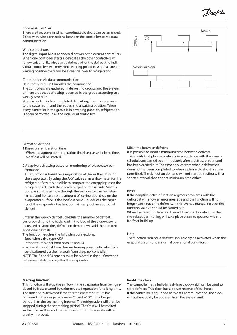
Coordinated defrostThere are two ways in which coordinated defrost can be arranged. Eitherwithwireconnectionsbetweenthecontrollersorviadatacommunication
WireconnectionsThedigitalinputDI2isconnectedbetweenthecurrentcontrollers.Whenonecontrollerstartsadefrostalltheothercontrollerswillfollowsuitandlikewisestartadefrost.Afterthedefrosttheindi-vidualcontrollerswillmoveintowaitingposition.Whenallareinwaitingpositiontherewillbeachange-overtorefrigeration.
CoordinationviadatacommunicationHerethesystemunithandlesthecoordination.The controllers are gathered in defrosting groups and the system unit ensures that defrosting is started in the group according to a weeklyschedule.Whenacontrollerhascompleteddefrosting,itsendsamessagetothesystemunitandthengoesintoawaitingposition.Wheneverycontrollerinthegroupisinawaitingposition,refrigerationisagainpermittedinalltheindividualcontrollers.
System manager
Defrost on demand1BasedonrefrigerationtimeWhentheaggregaterefrigerationtimehaspassedafixedtime,a defrost will be started.
2Adaptivedefrostingbasedonmonitoringofevaporatorper-formance This function is based on a registration of the air flow through theevaporator.ByusingtheAKVvalveasmassflowmeterfortherefrigerant flow it is possible to compare the energy input on the refrigerant side with the energy output on the air side. Via this comparisontheairflowthroughtheevaporatorcanbedeter-minedandhencealsotheamountofice/frostbuild-upontheevaporatorsurface.Iftheice/frostbuild-upreducesthecapac-ityoftheevaporatorthefunctionwillcarryoutanadditionaldefrost.
Enterintheweeklydefrostschedulethenumberofdefrostscorrespondingtothebasicload.Iftheloadoftheevaporatorisincreased beyond this, defrost on demand will add the required additional defrosts.The function requires the following connections:-ExpansionvalvetypeAKV-TemperaturesignalfrombothS3andS4-TemperaturesignalfromthecondensingpressurePcwhichistobedistributedviathenetworkfromthepackcontroller.
NOTE.TheS3andS4sensorsmustbeplacedintheairflow/chan-nelimmediatelybefore/aftertheevaporator.
Min. time between defrostsItispossibletoinputaminimumtimebetweendefrosts.Thisavoidsthatplanneddefrostsinaccordancewiththeweeklyschedule are carried out immediately after a defrost on demand has been carried out. The time applies from when a defrost on demand has been completed to when a planned defrost is again permitted. The defrost on demand will not start defrosting with a shorterintervalthanthesetminimumtimeeither.
ResetIftheadaptivedefrostfunctionregistersproblemswiththedefrost, it will show an error message and the function will no longercarryoutextradefrosts.Inthiseventamanualresetofthefunctionviad22shouldbecarriedout.Whentheresetfunctionisactivateditwillstartadefrostsothatthesubsequenttuningwilltakeplaceonanevaporatorwithnoice/frostbuild-up.
NoteThefunction"Adaptivedefrost”shouldonlybeactivatedwhentheevaporatorrunsundernormaloperationalconditions.
Melting functionThisfunctionwillstoptheairflowintheevaporatorfrombeingre-duced by frost created by uninterrupted operation for a long time.Thefunctionisactivatedifthethermostattemperaturehasremained in the range between -5°C and +10°C for a longer periodthanthesetmeltinginterval.Therefrigerationwillthenbestopped during the set melting period. The frost will be melted sothattheairflowandhencetheevaporator’scapacitywillbegreatlyimproved.
Real-time clockThecontrollerhasabuilt-inreal-timeclockwhichcanbeusedtostartdefrosts.Thisclockhasapowerreserveoffourhours.Ifthecontrollerisequippedwithdatacommunication,theclockwill automatically be updated from the system unit.
Max.4
8 Manual RS8EN302 © Danfoss 10-2008 AK-CC 550
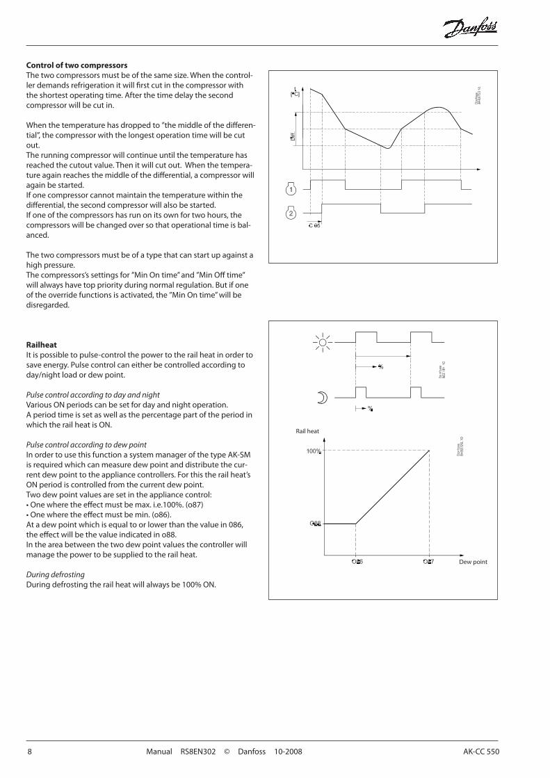
Control of two compressorsThetwocompressorsmustbeofthesamesize.Whenthecontrol-lerdemandsrefrigerationitwillfirstcutinthecompressorwiththe shortest operating time. After the time delay the second compressor will be cut in.
Whenthetemperaturehasdroppedto”themiddleofthedifferen-tial”,thecompressorwiththelongestoperationtimewillbecutout.The running compressor will continue until the temperature has reachedthecutoutvalue.Thenitwillcutout.Whenthetempera-tureagainreachesthemiddleofthedifferential,acompressorwillagain be started. Ifonecompressorcannotmaintainthetemperaturewithinthedifferential,thesecondcompressorwillalsobestarted.Ifoneofthecompressorshasrunonitsownfortwohours,thecompressorswillbechangedoversothatoperationaltimeisbal-anced.
The two compressors must be of a type that can start up against a high pressure.Thecompressors’ssettingsfor”MinOntime”and”MinOfftime”willalwayshavetoppriorityduringnormalregulation.Butifoneoftheoverridefunctionsisactivated,the”MinOntime”willbedisregarded.
RailheatItispossibletopulse-controlthepowertotherailheatinordertosaveenergy.Pulsecontrolcaneitherbecontrolledaccordingtoday/nightloadordewpoint.
Pulse control according to day and nightVariousONperiodscanbesetfordayandnightoperation.A period time is set as well as the percentage part of the period in whichtherailheatisON.
Pulse control according to dew pointInordertousethisfunctionasystemmanagerofthetypeAK-SMis required which can measure dew point and distribute the cur-rentdewpointtotheappliancecontrollers.Forthistherailheat’sONperiodiscontrolledfromthecurrentdewpoint.Twodewpointvaluesaresetintheappliancecontrol:•Onewheretheeffectmustbemax.i.e.100%.(o87)•Onewheretheeffectmustbemin.(o86).Atadewpointwhichisequaltoorlowerthanthevaluein086,theeffectwillbethevalueindicatedino88.Intheareabetweenthetwodewpointvaluesthecontrollerwillmanage the power to be supplied to the rail heat.
During defrostingDuringdefrostingtherailheatwillalwaysbe100%ON.
Dew point
Rail heat
AK-CC 550 Manual RS8EN302 © Danfoss 10-2008 9
Fan
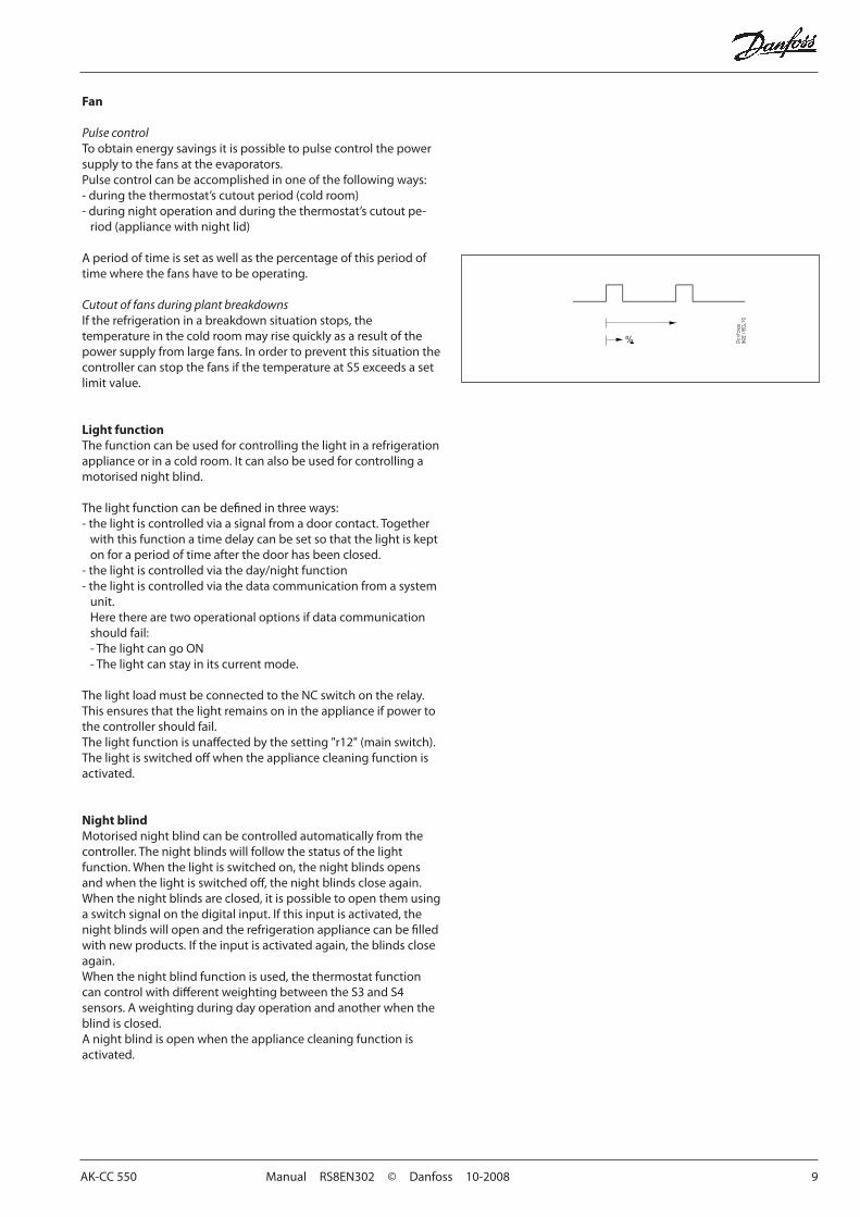
Pulse controlToobtainenergysavingsitispossibletopulsecontrolthepowersupplytothefansattheevaporators.Pulsecontrolcanbeaccomplishedinoneofthefollowingways:-duringthethermostat’scutoutperiod(coldroom)-duringnightoperationandduringthethermostat’scutoutpe-riod(appliancewithnightlid)
A period of time is set as well as the percentage of this period of timewherethefanshavetobeoperating.
Cutout of fans during plant breakdownsIftherefrigerationinabreakdownsituationstops,thetemperatureinthecoldroommayrisequicklyasaresultofthepowersupplyfromlargefans.Inordertopreventthissituationthecontroller can stop the fans if the temperature at S5 exceeds a set limitvalue.
Light functionThe function can be used for controlling the light in a refrigeration applianceorinacoldroom.Itcanalsobeusedforcontrollingamotorised night blind.
Thelightfunctioncanbedefinedinthreeways:-thelightiscontrolledviaasignalfromadoorcontact.Togetherwiththisfunctionatimedelaycanbesetsothatthelightiskepton for a period of time after the door has been closed.
-thelightiscontrolledviatheday/nightfunction-thelightiscontrolledviathedatacommunicationfromasystem
unit.Heretherearetwooperationaloptionsifdatacommunicationshould fail:-ThelightcangoON- The light can stay in its current mode.
The light load must be connected to the NC switch on the relay. This ensures that the light remains on in the appliance if power to the controller should fail.Thelightfunctionisunaffectedbythesetting"r12"(mainswitch).Thelightisswitchedoffwhentheappliancecleaningfunctionisactivated.
Night blindMotorised night blind can be controlled automatically from the controller. The night blinds will follow the status of the light function.Whenthelightisswitchedon,thenightblindsopensandwhenthelightisswitchedoff,thenightblindscloseagain.Whenthenightblindsareclosed,itispossibletoopenthemusingaswitchsignalonthedigitalinput.Ifthisinputisactivated,thenightblindswillopenandtherefrigerationappliancecanbefilledwithnewproducts.Iftheinputisactivatedagain,theblindscloseagain.Whenthenightblindfunctionisused,thethermostatfunctioncancontrolwithdifferentweightingbetweentheS3andS4sensors. A weighting during day operation and another when the blind is closed.A night blind is open when the appliance cleaning function is activated.
10 Manual RS8EN302 © Danfoss 10-2008 AK-CC 550
Refrigeration
Heat
Neutral zone
Digital inputsTherearetwodigitalinputsDI1andDI2withcontactfunctionandonedigitalinputDI3withhighvoltagesignal.They can be used for the following functions:-Retransmissionofcontactspositionviadatacommunication- Door contact function with alarm- Starting a defrost-Mainswitch-start/stopofcooling-Nightsetback- Thermostat bands switch-Generalalarmmonitoring- Case cleaning-Forcedcooling-Overrideofnightblinds-Coordinateddefrost(DI2only)-Forcedclosingofvalve(DI3only)
Forced closingTheAKVvalvescanbeclosedwithanexternalsignal("Forcedclosing").Thefunctionmustbeusedinconnectionwiththecompressor’ssafetycircuit,sothattherewillbenoinjectionofliquidintotheevaporatorwhenthecompressorisstoppedbythesafetycon-trols.(Howevernotatlowpressure–LP).Ifadefrostcycleisinprogress,theforcedclosingstatuswillnotbere-established until the defrost is completed.ThesignalcanbereceivedfromtheDI3-inputorviathedatacom-munication. Duringaforcedclosingthefanscanbedefinedtobestoppedorin operation.
Door contactThedoorcontactfunctioncanviathedigitalinputsbedefinedfortwodifferentapplications:Alarm monitoringThecontrollermonitorsthedoorcontactanddeliversanalarmmessage if the door has been opened for a longer period than the set alarm delay.
Alarm monitoring and stop of refrigerationWhenthedoorisopenedtherefrigerationisstopped,i.e.theinjection,thecompressorandthefanarestoppedandlightswitch on.Ifthedoorremainsopenforalongertimethanthesetrestarttime, refrigeration will be resumed. This will ensure that refrigerationismaintainedevenifthedoorisleftopenorifthedoorcontactshouldbedefective.Ifthedoorremainsopenfora longer period than the set alarm delay an alarm will also be triggered.
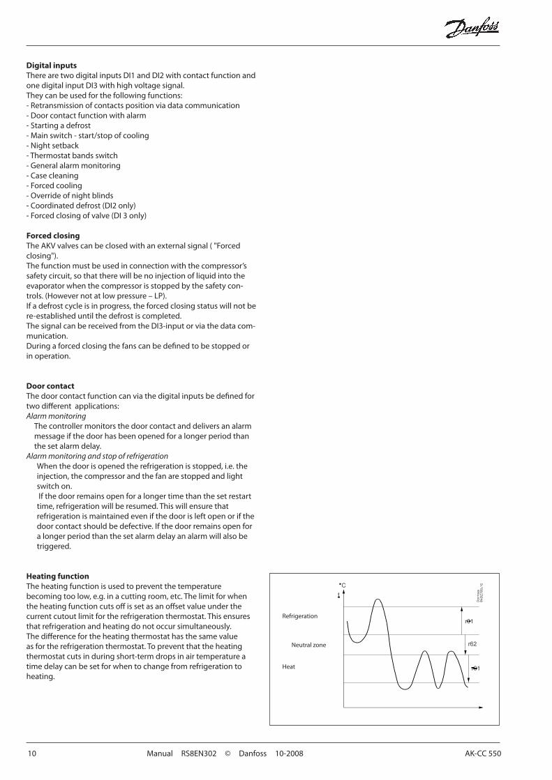
Heating functionTheheatingfunctionisusedtopreventthetemperaturebecoming too low, e.g. in a cutting room, etc. The limit for when theheatingfunctioncutsoffissetasanoffsetvalueunderthecurrent cutout limit for the refrigeration thermostat. This ensures that refrigeration and heating do not occur simultaneously. Thedifferencefortheheatingthermostathasthesamevalueasfortherefrigerationthermostat.Topreventthattheheatingthermostat cuts in during short-term drops in air temperature a time delay can be set for when to change from refrigeration to heating.
AK-CC 550 Manual RS8EN302 © Danfoss 10-2008 11
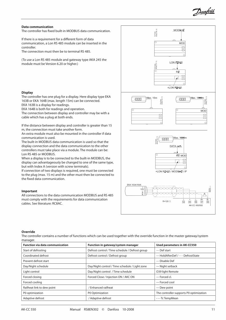
Data communicationThecontrollerhasfixedbuilt-inMODBUSdatacommunication.
Ifthereisarequirementforadifferentformofdatacommunication,aLonRS485modulecanbeinsertedinthecontroller.TheconnectionmustthenbetoterminalRS485.
(TouseaLonRS485moduleandgatewaytypeAKA245themodulemustbeVersion6.20orhigher.)
DisplayThecontrollerhasoneplugforadisplay.HeredisplaytypeEKA163BorEKA164B(max.length15m)canbeconnected.EKA163Bisadisplayforreadings.EKA164Bisbothforreadingsandoperation.The connection between display and controller may be with a cable which has a plug at both ends.
Ifthedistancebetweendisplayandcontrollerisgreaterthan15m,theconnectionmusttakeanotherform.An extra module must also be mounted in the controller if data communication is used.Thebuilt-inMODBUSdatacommunicationisusedsothatthedisplay connection and the data communication to the other controllersmusttakeplaceviaamodule.Themodulecanbe:LonRS485orMODBUS.Whenadisplayistobeconnectedtothebuilt-inMODBUS,thedisplaycanadvantageouslybechangedtooneofthesametype,butwithIndexA(versionwithscrewterminals).Ifconnectionoftwodisplaysisrequired,onemustbeconnectedtotheplug(max.15m)andtheothermustthenbeconnectedtothefixeddatacommunication.
ImportantAllconnectionstothedatacommunicationMODBUSandRS485must comply with the requirements for data communication cables. See literature: RC8AC.
OverrideThecontrollercontainsanumberoffunctionswhichcanbeusedtogetherwiththeoverridefunctioninthemastergateway/systemmanager.
Function via data communication Function in gateway/system manager Used parameters in AK-CC550
Start of defrosting Defrostcontrol/Timeschedule/Defrostgroup --- Def start
Coordinated defrost Defrostcontrol/Defrostgroup ---HoldAfterDef/---DefrostState
Preventdefroststart --- Disable Def
Day/Nightschedule Day/Nightcontrol/Timeschedule/Lightzone ---Nightsetback
Lightcontrol Day/Nightcontrol/Timeschedule O39lightRemote
Forcedclosing ForcedClose/InjectionON/AKCON ---Forcedcl.
Forcedcooling ---Forcedcool
Railheatlinktodewpoint /Enhancedrailheat --- Dew point
P0optimization P0Optimization ThecontrollersupportsP0optimization
Adaptivedefrost /Adaptivedefrost - - - Tc TempMean

12 Manual RS8EN302 © Danfoss 10-2008 AK-CC 550
Applications
Hereisasurveyofthecontroller’sfieldofapplication.
Asettingwilldefinetherelayoutputssothatthecontroller’sinterfacewillbetargetedtothechosenapplication.
Onpage20youcanseetherelevantsettingsfortherespectivewiringdiagrams.
S3andS4aretemperaturesensors.Theapplicationwilldeterminewhethereither one or the other or both sensors are to be used. S3 is placed in the air flowbeforetheevaporator.S4aftertheevaporator.A percentage setting will determine how the control is to be based. S5 is a defrostsensorandisplacedon/inthefinsoftheevaporator.S6isaproductsensor,butinapplication9and10ithasadifferentuse.DI1,DI2andDI3arecontactfunctionsthatcanbeusedforoneofthefol-lowing functions: door function, alarm function, defrost start, external main switch, night operation, change of thermostat reference, appliance cleaning, forcedrefrigerationorcoordinateddefrost.DI3hasa230Vinput.Seethefunctionsinsettingso02,o37ando84.
2
3
4
1
General:The ten uses are all adapted for commercial refrigeration systems in the form of either refrigeration appliances or cold storage rooms.Ingeneralallhaveoutputsfor:•AKVvalve•Fan•Defrost
Inadditiontheyhavedifferentusesandtherebyinput and outputs.
Application 1-4 Standard applications.Thisisforstandardusewherethevitaldifferenceisonlydifferentcombinationsofthefollowingfunctions/outputs:•Alarm•Railheat•Compressor•Light

AK-CC 550 Manual RS8EN302 © Danfoss 10-2008 13
5
6
7
9
10
8
Thefollowinguseshavesomespecialfunctionswhich in brief are:
Application 5 ”Two-compressor”operation.The two compressors must be of the same size. Onstart-up(afterdefrosting,operationalstop,etc.)bothcompressorsarestartedwithasettimeshift.Onecompressorstartsathalfthedifferentialso that an optimum adaptation of compressor capacitytakesplaceforthecurrentloadintheappliance/room.Thereisautomaticruntimeequalisation between the compressors.Foramoredetaileddescriptionpleaserefertoearlier sections in the manual.
Application 6Hotgasdefrosting.Hotgasdefrostingisadaptedtocommercialappliances/roomswithlimitedsystemfilling.Onerelaycontrolsthemainvalveinthesuctionline. Achangeoverrelaycontrolsboththehotgasvalveandthedrainvalve.This means that there is no time delay between stops of hot gas and start of draining.
Application 7Control of night blindsNight blinds follow the status of the light function – when the light is switched on, the night blinds areupandwhenthelightisswitchedoff,thenightblindsaredown.Inadditionadigitalinputprovidestheoptionofforcedopeningoftheblindssothattheappliancecanbefilledwithproducts. Application 8 HeatthermostatThe heat thermostat is typically used if the temperature is to be controlled within narrower limits, e.g. for cutting rooms, etc. The heating thermostatcanbesetasadifferenceinrelationtothe cutout limit for the refrigeration thermostat so that simultaneous refrigeration and heating are avoided.
Application 9 Two refrigeration sections – two defrost outputsThis application is for refrigeration appliances with onevalve,twoevaporatorsandtworefrigerationsections. The temperature is controlled and is alwaysalarmmonitoredaccordingtotheS4temperature.Forthistheproductsensorisusedasadefrostingstopsensorforevaporatorno.2.
Application 10 Tworefrigerationsections–individualalarm/displayviaS3This application is for refrigeration appliances with onevalve,oneevaporatorandtworefrigerationsections. The temperature is always controlled accordingtotheS4temperature.Theproductsensor is used as an extra S3 sensor for section no.2.Alarmmonitoringanddisplayreadingstakeplaceindividuallyviathe"S3"sensorsineachrefrigeration section.

14 Manual RS8EN302 © Danfoss 10-2008 AK-CC 550
Connection signs
Thecontrollerisprovidedwithsignsfromthefactoryindicatingapplication 1.Ifyouemployanotheruse,signsareprovidedsothatyoucanmounttherelevantone.Itisonlythelowersignthatneedstobemounted.
Thenumberisindicatedontheleft-handsideofthesigns.Usethesignwiththecurrentapplicationnumber.Oneofthesignsappliestobothapplications4and10.

AK-CC 550 Manual RS8EN302 © Danfoss 10-2008 15
Survey of functionsFunction Para-
meterParameter by operation via data communication
Normal display
NormallythetemperaturevaluefromoneofthetwothermostatsensorsS3orS4oramixture of the two measurements is displayed. Ino17theratioisdetermined.
Displayair(u56)
Thermostat Thermostat controlSet pointRegulationisbasedonthesetvalueplusadisplacement,ifapplicable.Thevalueissetviaapushonthecentrebutton.Thesetvaluecanbelockedorlimitedtoarangewiththesettingsinr02andr03.The reference at any time can be seen in "u91 Cutout temp".
Cutout °C
DifferentialWhenthetemperatureishigherthanthereference+thesetdifferential,thecom-pressorrelaywillbecutin.Itwillcutoutagainwhenthetemperaturecomesdowntothe set reference.
r01 Differential
Setpoint limitationThecontroller’ssettingrangeforthesetpointmaybenarroweddown,sothatmuchtoohighormuchtoolowvaluesarenotsetaccidentally-withresultingdamages.
Toavoidatoohighsettingofthesetpoint,themax.allowablereferencevaluemaybelowered.
r02 Max cutout °C
Toavoidatoolowsettingofthesetpoint,themin.allowablereferencevaluemaybeincreased.
r03 Min cutout °C
Correction of the display’s temperature Ifthetemperatureattheproductsandthetemperaturereceivedbythecontrollerarenotidentical,anoffsetadjustmentofthedisplaytemperaturecanbecarriedout.
r04 Disp.Adj.K
Temperature unitSethereifthecontrolleristoshowtemperaturevaluesin°Corin°F.
r05 Temp. unit °C=0./°F=1(Only°ConAKM,whatevertheset-ting)
Correction of signal from S4Compensation possibility due to long sensor cable
r09 AdjustS4
Correction of signal from S3Compensation possibility due to long sensor cable
r10 AdjustS3
Start / stop of refrigerationWiththissettingrefrigerationcanbestarted,stoppedoramanualoverrideoftheoutputscanbeallowed.(Formanualcontrolthevalueissetat-1.ThentheAKVoutletandtherelayoutletscanbeforce-controlledbytherespectivereadingparameters(u23,u58,etc.).Herethereadvaluecanbeoverwritten.)Start/stopofrefrigerationcanalsobeaccomplishedwiththeexternalswitchfunc-tionconnectedtoaDIinput.Stoppedrefrigerationwillgivea”Standbyalarm”.
r12 Main Switch
1: Start0: Stop
-1: Manual control of outputs allowed
Night setback valueThethermostat’sreferencewillbethesetpointplusthisvaluewhenthecontrollerchangesovertonightoperation.(Selectanegativevalueifthereistobecoldac-cumulation.)
r13 Nightoffset
Thermostat functionHereitisdefinedhowthethermostatistooperate.EitherasanordinaryON/OFFther-mostat or as a modulating thermostat.1:ON/OFFthermostat2: Modulating
Whenoperationis”modulating”theAKVvalvewilllimittheflowofrefrigerantsothatthetemperaturevariationwillbelessthanfortheON/OFFthermostat.Thedifferential(r01)mustnotbesetlowerthan2Kfor"modulating".
InadecentralisedplantyoumustselecttheON/OFFthermostatsetting.
r14 Therm. mode
Selection of thermostat sensorHereyoudefinethesensorthethermostatistouseforitscontrolfunction.S3,S4,oracombinationofthem.Withthesetting0%,onlyS3isused(Sin).With100%,onlyS4.
r15 Ther.S4%
Ref. Dif.
16 Manual RS8EN302 © Danfoss 10-2008 AK-CC 550
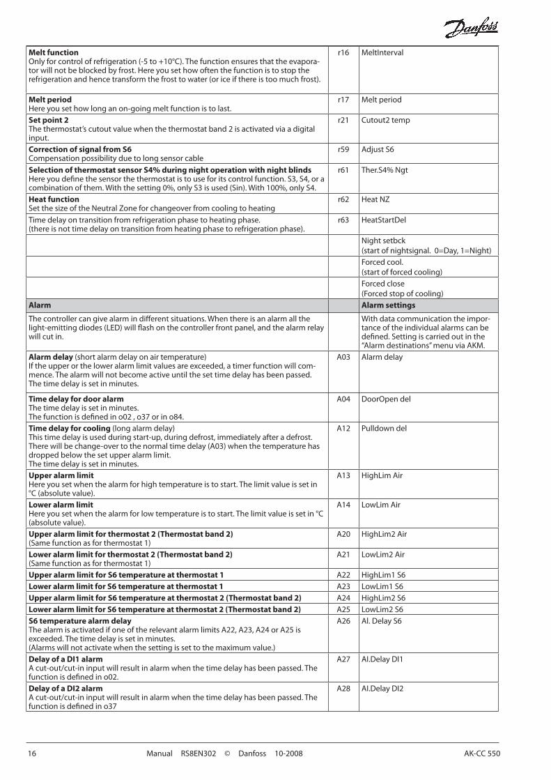
Melt functionOnlyforcontrolofrefrigeration(-5to+10°C).Thefunctionensuresthattheevapora-torwillnotbeblockedbyfrost.Hereyousethowoftenthefunctionistostoptherefrigerationandhencetransformthefrosttowater(oriceifthereistoomuchfrost).
r16 MeltInterval
Melt periodHereyousethowlonganon-goingmeltfunctionistolast.
r17 Melt period
Set point 2 Thethermostat’scutoutvaluewhenthethermostatband2isactivatedviaadigitalinput.
r21 Cutout2 temp
Correction of signal from S6Compensation possibility due to long sensor cable
r59 AdjustS6
Selection of thermostat sensor S4% during night operation with night blindsHereyoudefinethesensorthethermostatistouseforitscontrolfunction.S3,S4,oracombinationofthem.Withthesetting0%,onlyS3isused(Sin).With100%,onlyS4.
r61 Ther.S4%Ngt
Heat functionSetthesizeoftheNeutralZoneforchangeoverfromcoolingtoheating
r62 HeatNZ
Time delay on transition from refrigeration phase to heating phase.(thereisnottimedelayontransitionfromheatingphasetorefrigerationphase).
r63 HeatStartDel
Nightsetbck(startofnightsignal.0=Day,1=Night)Forcedcool.(startofforcedcooling)Forcedclose (Forcedstopofcooling)
Alarm Alarm settings
Thecontrollercangivealarmindifferentsituations.Whenthereisanalarmallthelight-emittingdiodes(LED)willflashonthecontrollerfrontpanel,andthealarmrelaywill cut in.
Withdatacommunicationtheimpor-tanceoftheindividualalarmscanbedefined.Settingiscarriedoutinthe“Alarmdestinations”menuviaAKM.
Alarm delay (shortalarmdelayonairtemperature)Iftheupperortheloweralarmlimitvaluesareexceeded,atimerfunctionwillcom-mence.Thealarmwillnotbecomeactiveuntilthesettimedelayhasbeenpassed.The time delay is set in minutes.
A03 Alarm delay
Time delay for door alarmThe time delay is set in minutes.Thefunctionisdefinedino02,o37orino84.
A04 DoorOpendel
Time delay for cooling (longalarmdelay)This time delay is used during start-up, during defrost, immediately after a defrost.Therewillbechange-overtothenormaltimedelay(A03)whenthetemperaturehasdropped below the set upper alarm limit.The time delay is set in minutes.
A12 Pulldowndel
Upper alarm limitHereyousetwhenthealarmforhightemperatureistostart.Thelimitvalueissetin°C(absolutevalue).
A13 HighLimAir
Lower alarm limitHereyousetwhenthealarmforlowtemperatureistostart.Thelimitvalueissetin°C(absolutevalue).
A14 LowLimAir
Upper alarm limit for thermostat 2 (Thermostat band 2)(Samefunctionasforthermostat1)
A20 HighLim2Air
Lower alarm limit for thermostat 2 (Thermostat band 2)(Samefunctionasforthermostat1)
A21 LowLim2Air
Upper alarm limit for S6 temperature at thermostat 1 A22 HighLim1S6Lower alarm limit for S6 temperature at thermostat 1 A23 LowLim1S6Upper alarm limit for S6 temperature at thermostat 2 (Thermostat band 2) A24 HighLim2S6Lower alarm limit for S6 temperature at thermostat 2 (Thermostat band 2) A25 LowLim2S6S6 temperature alarm delayThealarmisactivatedifoneoftherelevantalarmlimitsA22,A23,A24orA25is exceeded. The time delay is set in minutes.(Alarmswillnotactivatewhenthesettingissettothemaximumvalue.)
A26 Al.DelayS6
Delay of a DI1 alarmAcut-out/cut-ininputwillresultinalarmwhenthetimedelayhasbeenpassed.Thefunctionisdefinedino02.
A27 AI.DelayDI1
Delay of a DI2 alarm Acut-out/cut-ininputwillresultinalarmwhenthetimedelayhasbeenpassed.Thefunctionisdefinedino37
A28 AI.DelayDI2

AK-CC 550 Manual RS8EN302 © Danfoss 10-2008 17
Signal to the alarm thermostat Hereyouhavetodefinetheratiobetweenthesensorswhichthealarmthermostathastouse.S3,S4oracombinationofthetwo.Withsetting0%onlyS3isused.With100%onlyS4isused
A36 AlarmS4%
Time delay on S6 (product sensor) for pull-down(longalarmdelay)This time delay is used for start-up, during defrosting, immediately after a defrost and after an appliance clean.Achangeiscarriedouttostandardtimedelay(A26)whenthetemperaturehasreached below the set upper alarm limit.The time delay is set in minutes.
A52 PullDdel.S6
Reset alarmCtrl.Error(EKCerror)
Compressor Compressor control
Thecompressorrelayworksinconjunctionwiththethermostat.Whenthethermo-stat calls for refrigeration the compressor relay be operated.
Running timesTopreventirregularoperation,valuescanbesetforthetimethecompressoristorunonce it has been started. And for how long it at least has to be stopped.Therunningtimesarenotobservedwhendefrostsstart.
Min.ON-time(inminutes) c01 Min.OntimeMin.OFF-time(inminutes) c02 Min.OfftimeTime delay for couplings of two compressorsSettingsindicatethetimethathastoelapsefromthefirstrelaycutsinanduntilthenext relay has to cut in.
c05 Step delay
TheLEDonthecontroller’sfrontwillshowwhetherrefrigerationisinprogress. Comp RelayHereyoucanreadthestatusofthecompressor relay.
Defrost Defrost controlThe controller contains a timer function that is zeroset after each defrost start.Thetimerfunctionwillstartadefrostif/whentheintervaltimeispassed.Thetimerfunctionstartswhenvoltageisconnectedtothecontroller,butitisdis-placedthefirsttimebythesettingind05.Ifthereispowerfailurethetimervaluewillbesavedandcontinuefromherewhenthe power returns.This timer function can be used as a simple way of starting defrosts, but it will always actassafetydefrostifoneofthesubsequentdefroststartsisnotreceived.Thecontrolleralsocontainsareal-timeclock.Bymeansofsettingsofthisclockandtimesfortherequireddefrosttimes,defrostcanbestartedatfixedtimesoftheday.Defroststartcanalsobeaccomplishedviadatacommunication,viacontactsignalsormanual start-up.Allstartingmethodswillfunctioninthecontroller.Thedifferentfunctionshavetobeset,sothatmultipledefrostsareavoided..Defrost can be accomplished with electricity, hotgas or brine.The actual defrost will be stopped based on time or temperature with a signal from a temperature sensor.Defrost methodHereyousetwhetherdefrostistobeaccomplishedwithelectricity,gas,or(none).During defrost the defrost relay will be cut in.
d01 Def. method0 = non1 = El2=Gas
Defrost stop temperatureThedefrostisstoppedatagiventemperaturewhichismeasuredwithasensor(thesensorisdefinedind10).Thetemperaturevalueisset.
d02 Def. Stop Temp

18 Manual RS8EN302 © Danfoss 10-2008 AK-CC 550
Interval between defrost startsThefunctioniszerosetandwillstartthetimerfunctionateachdefroststart.Whenthe time has expired the function will start a defrost.The function is used as a simple defrost start, or it may be used as a safeguard if the normal signal fails to appear.Ifmaster/slavedefrostwithoutclockfunctionorwithoutdatacommunicationisused,theintervaltimewillbeusedasmax.timebetweendefrosts.Ifadefroststartviadatacommuncationdoesnottakeplace,theintervaltimewillbeused as max. time between defrosts.Whenthereisdefrostwithclockfunctionordatacommunication,theintervaltimemust be set for a somewhat longer period of time than the planned one, as the intervaltimewillotherwisestartadefrostwhichalittlelaterwillbefollowedbytheplanned one.Inconnectionwithpowerfailuretheintervaltimewillbemaintained,andwhenthepowerreturnstheintervaltimewillcontinuefromthemaintainedvalue.Theintervaltimeisnotactivewhensetto0.
d03 DefInterval(0=off)
Max. defrost durationThis setting is a safety time so that the defrost will be stopped if there has not already beenastopbasedontemperatureorviacoordinateddefrost.
d04 Max Def. time
Time staggering for defrost cutins during start-upThefunctionisonlyrelevantifyouhaveseveralrefrigerationappliancesorgroupswhere you want the defrost to be staggered in relation to one another. The function is furthermoreonlyrelevantifyouhavechosendefrostwithintervalstart(d03).Thefunctiondelaystheintervaltimed03bythesetnumberofminutes,butitonlydoesitonce,andthisattheveryfirstdefrosttakingplacewhenvoltageisconnectedto the controller.Thefunctionwillbeactiveaftereachandeverypowerfailure.
d05 Time Stagg.
Drip-off timeHereyousetthetimethatistoelapsefromadefrostanduntilthecompressoristostartagain.(Thetimewhenwaterdripsofftheevaporator).
d06 DripOfftime
Delay of fan start after defrostHereyousetthetimethatistoelapsefromcompressorstartafteradefrostanduntilthefanmaystartagain.(Thetimewhenwateris“tied”totheevaporator).
d07 FanStartDel
Fan start temperatureThe fan may also be started a little earlier than mentioned under “Delay of fan start afterdefrost”,ifthedefrostsensorS5registersalowervaluethantheonesethere.
d08 FanStartTemp
Fan cut in during defrostHereyoucansetwhetherfanistooperateduringdefrost.
d09 FanDuringDef0=no1=yes
Defrost sensor Hereyoudefinethedefrostsensor.0: None, defrost is based on time1: S52:S43:Sx.Forapplication1to8and10defrostingisstoppedwhenbothS5andS6have
reachedthesettemperature.Forapplication9defrostingisstoppedindividu-allyonthetwosectionsofS5/S5B
d10 DefStopSens.
Pumpdown delaySetthetimewheretheevaporatorisemptiedofrefrigerantpriortothedefrost.
d16 Pumpdwndel.
Drain delay (only in connection with hotgas)Setthetimewheretheevaporatorisemptiedofcondensedrefrigerantafterthedefrost.
d17 Drain del
Defrost on demand – aggregate refrigeration timeSethereistherefrigerationtimeallowedwithoutdefrosts.Ifthetimeispassed,adefrost will be started.Withsetting=0thefunctioniscutout.
d18 MaxTherRunT
Delay on stop of heating in the drip trayThe time applies from the time the defrost stops by time or temperature to the time the heating element in the drip tray needs to be disconnected.
d20 Drip Tray del
Adaptive defrostingAnadaptivedefrostingisanextradefrostinadditiontothescheduleddefrosts.Heretheadaptivedefrostissetforwhenitcanstartadefrostiftheneedarises:0:Never1:Onlyalarmoniceover2:Itmayonlystartduringdayoperation3:Itmaystartbothduringdayandnightoperation4:Itcanonlystartduringnightoperations
d21 AD mode

AK-CC 550 Manual RS8EN302 © Danfoss 10-2008 19
Restart of adaptive defrostingThe function starts a defrost and when it is complete, the tuning function restarts so thattheevaporator’sdatacanberegistered.MUSTONLYBEACTIVATEDDURINGSTANDARDOPERATION.
d22 AD reset
Ifyouwishtoseethetemperatureatthedefrostsensor,pushthecontroller’slower-mostbutton.(Maybechangedtoanotherfunctionino92.)
Defrost temp.
Ifyouwishtostartanextradefrost,pushthecontroller’slowermostbuttonforfourseconds.Youcanstopanongoingdefrostinthesameway
Def StartHereyoucanstartamanualdefrost
HoldAfterDefShowsONwhenthecontrollerisoperating with coordinated defrost.
Parameter for cooling functionIntegration timeExpertsettingforinjectionfunctionThevalueshouldonlybechangedbyspeciallytrainedstaff.
n05 Tn sec
Max. value for the superheat reference n09 MaxSHMin. value for the superheat reference n10 MinSHMOP temperatureIfnoMOPfunctionisrequired,selectpos.OFF
n11 MOPtemp(Avalueof15correspondstoOFF)
Temperatureglide (only when using of S1-temperature sensor)Ifazeotroperefrigerantisused,avaluefortemperatureglidemustbeset.
n12 Glide
AKV valve’s time period in secondsShouldonlybesettoalowervalueifitisadecentralisedplantandthesuction pressurefluctuatesalotandinlinewiththeopeningoftheAKVvalve.
n13 AKVPeriod
Startup time for signal reliabilityIfthecontrollerdoesnotobtainareliableS1signalwithinthisperiodoftimeitwillinotherwaystrytocreateastablesignal.(Atoohighvaluemayresultinafloodedevaporator).Thevalueshouldonlybechangedbyspeciallytrainedstaff.
n15 StartUptime
Average opening degreeThecontrollercontinuouslyregistersthevalve’sopeningdegreeandusesthevalueinits regulation.Thevalueshouldonlybechangedbyspeciallytrainedstaff.
n16 AKV Dim.
Signal reliability at startupTheregulationusesthevalueasstartvalueforthevalve’sopeningdegreeforeachthermostatcutin.Inconnectionwithadaptivecontrolthecontrollercontinuouslycalculatesanewvalue.Thevalueshouldonlybechangedbyspeciallytrainedstaff.
n17 StartOD%
Stability factor for regulation of superheat (Stability)Withahighervaluethecontrolfunctionwillallowagreaterfluctuationofthesuper-heat before the reference is changed.Thevalueshouldonlybechangedbyspeciallytrainedstaff.(Factorysetting=0.4.)
n18 -
Ampflication factorExpertsettingforinjectionfunctionThevalueshouldonlybechangedbyspeciallytrainedstaff.
n23 MTR Kp factor
Integration timeExpertsettingforinjectionfunctionThevalueshouldonlybechangedbyspeciallytrainedstaff.
n24 MTR Tn sec
Choice of sensor for superheat function (canonlybesetif"r12"=0)1:PressuretransmittertypeAKS32R2:TemperaturesensorS1(Pt1000Ohmat0°C)
n57 Pe/S1select
Fan Fan controlFan stop temperatureThefunctionstopsthefansinanerrorsituation,sothattheywillnotprovidepowertotheappliance.Ifthedefrostsensorregistersahighertemperaturethantheonesethere, the fans will be stopped. There will be re-start at 2 K below the setting.Thefunctionisnotactiveduringadefrostorstart-upafteradefrost.Withsetting+50°Cthefunctionisinterrupted.
F04 FanStopTemp.
Pulse operation of fan0: No pulse operation1:Pulseoperationwhenthethermostatdoesnotcallforrefrigeration2:Pulseoperationwhenthethermostatdoesnotcallforrefrigeration,butonlydur-ing night operation
F05 FanPulseMode
Pulse operation period for fanHeretheoverallpulsetimeisset.ThesumofON-toandOFFtime.
F06 Fancycle
ON time for fanHerethe%partoftheperiodthefansaretobeinoperationisset.
F07 FanON%

20 Manual RS8EN302 © Danfoss 10-2008 AK-CC 550
TheLEDonthecontroller’sfrontwillindicatewhetheradefrostisgoingon. FanRelayHereyoucanreadthefanrelaystatus,or force-control the relay in “Manual control”mode.
Real time clockWhenusingdatacommunicationtheclockisautomaticallyadjustedbythesystemunit.Ifthecontrolleriswithoutdatacommunication,theclockwillhaveapowerreserveoffourhours.
(Timescannotbesetviadatacom-munication.Settingsareonlyrelevantwhen there is no data communica-tion).
Real-time clock Youcansetuptosixindividualtimesfordefroststartsforeach24-hourperiod.Thereis also a date indication used for registration of temperature measurements.Defrost start, hour setting t01-t06Defroststart,minutesetting(1and11belongtogether,etc.)Whenallt01tot16equal0theclockwillnotstartdefrosts.
t11-t16
Clock:Hoursetting t07
Clock:Minutesetting t08
Clock:Datesetting t45
Clock:Monthsetting t46
Clock:Yearsetting t47
Miscellaneous MiscellaneousDelay of output signal after start-upAfterstart-uporapowerfailurethecontroller’sfunctionscanbedelayedsothatover-loadingoftheelectricitysupplynetworkisavoided.Hereyoucansetthetimedelay.
o01 DelayOfOutp.
Digital input signal - DI1The controller has a digital input 1 which can be used for one of the following func-tions:Off:Theinputisnotused1)Statusdisplayofacontactfunction2)Doorfunction.Whentheinputisopenitsignalsthatthedoorisopen.Therefrig-erationandthefansarestoppedandlightswitchedon.Whenthetimesettingin“A04”ispassed,analarmwillbegivenandrefrigerationwillberesumed(o89).
3)Dooralarm.Whentheinputisopenitsignalsthatthedoorisopen.Whenthetimesettingin“A04”ispassed,therewillbealarm.
4)Defrost.Thefunctionisstartedwithapulsesignal.The controller will register when theDIinputisactivated.Thecontrollerwillthenstartadefrostcycle.
5)Mainswitch.Regulation is carried out when the input is short-circuited, and regula-tionisstoppedwhentheinputisputinpos.OFF.
6)Nightoperation.Whentheinputisshort-circuited,therewillberegulationfornight operation.
7)Thermostatbandchangeover.Switchtothermostat2(r21).8)Separatealarmfunction.Alarmwillbegivenwhentheinputisshort-circuited.9)Separatealarmfunction.Alarmwillbegivenwhentheinputisopened.(For8and9thetimedelayissetinA27)
10)Casecleaning.Thefunctionisstartedwithapulsesignal.Seealsodescriptiononpage 5.
11)Forcedrefrigerationathotgasdefrostwhentheinputisshort-circuited.12)Nightcover
o02 DI1Config.Definitiontakesplacewiththenu-mericalvalueshowntotheleft.
(0=off)
DIstate(Measurement)TheDIinput’spresentstatusisshownhere.ONorOFF.
Ifthecontrollerisbuiltintoanetworkwithdatacommunication,itmusthaveanaddress, and the mastergatewayofthedatacommunicationmustthenknowthisaddress.
Theaddressissetbetween0and240,dependingonthesystemunitandtheselecteddatacommunication.IfthesystemunitisgatewaytypeAKA245,theversionmustbe6.20orhigher.
o03
Theaddressissenttothegatewaywhenthemenuissetinpos.ONIMPORTANT:Beforeyouseto04,youMUSTseto61.Otherwiseyouwillbetransmit-ting incorrect data.(ThefunctionisnotusedwhenthedatacommunicationisMODBUS)
o04
Access code 1 (Access to all settings)Ifthesettingsinthecontrolleraretobeprotectedwithanaccesscodeyoucansetanumericalvaluebetween0and100.Ifnot,youcancancelthefunctionwithsetting0.(99willalwaysgiveyouaccess).
o05 -
Sensor type for S3, S4, S5, S6NormallyaPt1000sensorwithgreatsignalaccuracyisused.Butyoucanalsouseasensorwithanothersignalaccuracy.ThatmayeitherbeaPTCsensor(1000ohmat25°C)AllthemountedsensorsS3-S6mustbeofthesametype.
o06 SensorConfigPt=0PTC=1
AK-CC 550 Manual RS8EN302 © Danfoss 10-2008 21
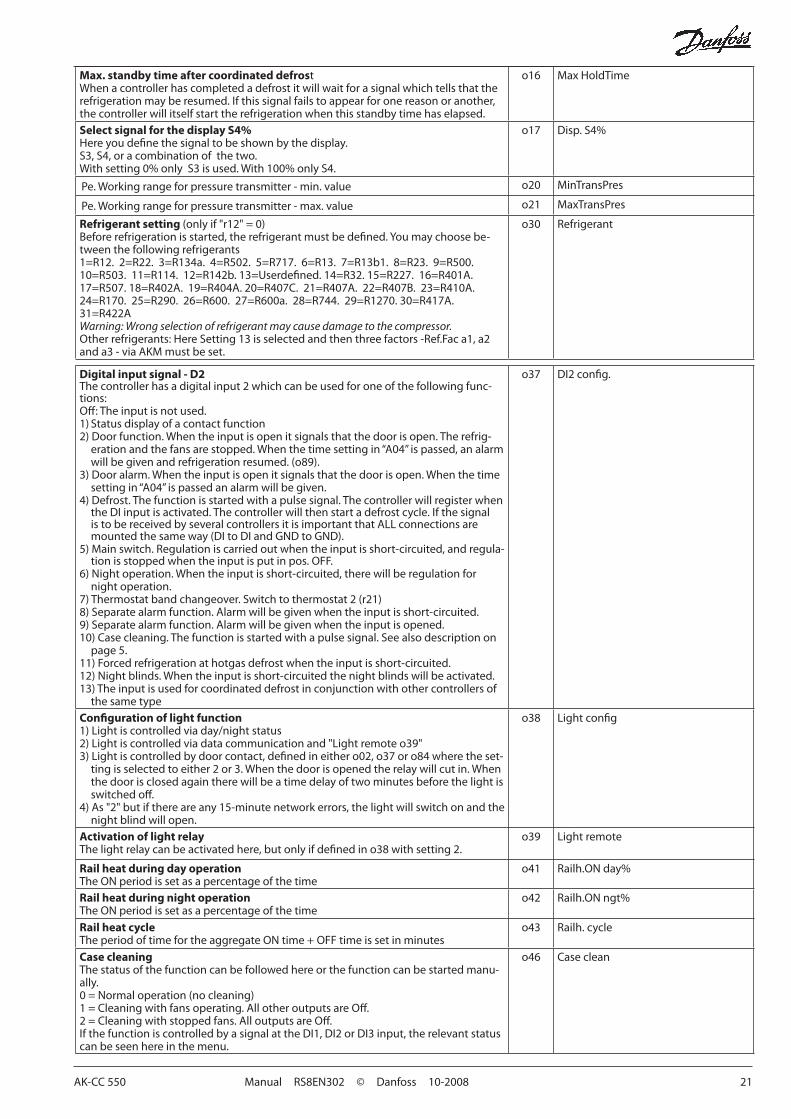
Max. standby time after coordinated defrostWhenacontrollerhascompletedadefrostitwillwaitforasignalwhichtellsthattherefrigerationmayberesumed.Ifthissignalfailstoappearforonereasonoranother,the controller will itself start the refrigeration when this standby time has elapsed.
o16 MaxHoldTime
Select signal for the display S4%Hereyoudefinethesignaltobeshownbythedisplay.S3,S4,oracombinationofthetwo.Withsetting0%onlyS3isused.With100%onlyS4.
o17 Disp.S4%
Pe.Workingrangeforpressuretransmitter-min.value o20 MinTransPres
Pe.Workingrangeforpressuretransmitter-max.value o21 MaxTransPres
Refrigerant setting (onlyif"r12"=0)Beforerefrigerationisstarted,therefrigerantmustbedefined.Youmaychoosebe-tween the following refrigerants1=R12.2=R22.3=R134a.4=R502.5=R717.6=R13.7=R13b1.8=R23.9=R500.10=R503.11=R114.12=R142b.13=Userdefined.14=R32.15=R227.16=R401A.17=R507.18=R402A.19=R404A.20=R407C.21=R407A.22=R407B.23=R410A.24=R170.25=R290.26=R600.27=R600a.28=R744.29=R1270.30=R417A.31=R422AWarning: Wrong selection of refrigerant may cause damage to the compressor.Otherrefrigerants:HereSetting13isselectedandthenthreefactors-Ref.Faca1,a2anda3-viaAKMmustbeset.
o30 Refrigerant
Digital input signal - D2The controller has a digital input 2 which can be used for one of the following func-tions:Off:Theinputisnotused.1)Statusdisplayofacontactfunction2)Doorfunction.Whentheinputisopenitsignalsthatthedoorisopen.Therefrig-erationandthefansarestopped.Whenthetimesettingin“A04”ispassed,analarmwillbegivenandrefrigerationresumed.(o89).
3)Dooralarm.Whentheinputisopenitsignalsthatthedoorisopen.Whenthetimesettingin“A04”ispassedanalarmwillbegiven.
4)Defrost.Thefunctionisstartedwithapulsesignal.The controller will register when theDIinputisactivated.Thecontrollerwillthenstartadefrostcycle.IfthesignalistobereceivedbyseveralcontrollersitisimportantthatALLconnectionsaremountedthesameway(DItoDIandGNDtoGND).
5)Mainswitch.Regulation is carried out when the input is short-circuited, and regula-tionisstoppedwhentheinputisputinpos.OFF.
6)Nightoperation.Whentheinputisshort-circuited,therewillberegulationfornight operation.
7)Thermostatbandchangeover.Switchtothermostat2(r21)8)Separatealarmfunction.Alarmwillbegivenwhentheinputisshort-circuited.9)Separatealarmfunction.Alarmwillbegivenwhentheinputisopened.10)Casecleaning.Thefunctionisstartedwithapulsesignal.Seealsodescriptionon
page 5.11)Forcedrefrigerationathotgasdefrostwhentheinputisshort-circuited.12)Nightblinds.Whentheinputisshort-circuitedthenightblindswillbeactivated.13)Theinputisusedforcoordinateddefrostinconjunctionwithothercontrollersof
the same type
o37 DI2config.
Configuration of light function1)Lightiscontrolledviaday/nightstatus2)Lightiscontrolledviadatacommunicationand"Lightremoteo39"3)Lightiscontrolledbydoorcontact,definedineithero02,o37oro84wheretheset-tingisselectedtoeither2or3.Whenthedoorisopenedtherelaywillcutin.Whenthe door is closed again there will be a time delay of two minutes before the light is switchedoff.
4)As"2"butifthereareany15-minutenetworkerrors,thelightwillswitchonandthenight blind will open.
o38 Lightconfig
Activation of light relayThelightrelaycanbeactivatedhere,butonlyifdefinedino38withsetting2.
o39 Lightremote
Rail heat during day operationTheONperiodissetasapercentageofthetime
o41 Railh.ONday%
Rail heat during night operationTheONperiodissetasapercentageofthetime
o42 Railh.ONngt%
Rail heat cycleTheperiodoftimefortheaggregateONtime+OFFtimeissetinminutes
o43 Railh. cycle
Case cleaningThe status of the function can be followed here or the function can be started manu-ally.0=Normaloperation(nocleaning)1=Cleaningwithfansoperating.AllotheroutputsareOff.2=Cleaningwithstoppedfans.AlloutputsareOff.IfthefunctioniscontrolledbyasignalattheDI1,DI2orDI3input,therelevantstatuscan be seen here in the menu.
o46 Case clean

22 Manual RS8EN302 © Danfoss 10-2008 AK-CC 550
Selection of applicationThecontrollercanbedefinedinvariousways.Hereyousetwhichofthe10applica-tionsisrequired.Onpage12youcanseeasurveyofapplications.This menu can only be set when regulation is stopped, i.e. “r12” is set to 0.
o61 --- Appl. Mode (onlyoutputinDanfossonly)
Transfer a set of pre-settings to the controllerAnoptionexiststoselectquicksettingsforanumberofparameters.Thisisbasedonwhether an appliance or a room needs to be controlled or whether the defrosting mustbestoppedbytimeorbytemperature.Theoverviewcanbeseenonpage27.This menu can only be set when the control is stopped, i.e. When "r12" is set at 0.
Onsettingthevaluewillfallbackto0.Asubsequentadjustment/settingofparam-eters can be carried out as required.
o62 -
Access code 2 (Access to adjustments)Thereisaccesstoadjustmentsofvalues,butnottoconfigurationsettings.Iftheset-tings in the controller are to be protected with an access code you can set a numeri-calvaluebetween0and100.Ifnot,youcancancelthefunctionwithsetting0.Ifthefunctionisused,accesscode1(o05)must also be used.
o64 -
Copy the controller’s present settingsWiththisfunctionthecontroller’ssettingscanbetransferredtoaprogrammingkey.Thekeycancontainupto25differentsets.Selectanumber.AllsettingsexceptforAddress(o03)willbecopied.Whencopyinghasstartedthedisplayreturnstoo65.Aftertwosecondsyoucanmoveintothemenuagainandcheckwhetherthecopyingwas satisfactory.Anegativefigurespellsproblems.SeethesignificanceintheFaultMessagesection.
o65 -
Copy from the programming keyThisfunctiondownloadsasetofsettingsearliersavedinthecontroller.Selecttherelevantnumber.AllsettingsexceptforAddress(o03)willbecopied.Whencopyinghasstartedthedisplayreturnstoo66.Aftertwosecondsyoucanmovebackintothemenuagainandcheckwhetherthecopyingwassatisfactory.Anegativefigurespellsproblems.SeethesignificanceintheFaultMessagesection.
o66 -
Save as factory settingWiththissettingyousavethecontroller’sactualsettingsasanewbasicsetting(theearlierfactorysettingsareoverwritten).
o67 -
Digital input signal - DI3 (high voltage input) The controller has a digital input 3 which can be used for one of the following func-tions:Off:Theinputisnotused.1)Statusdisplayof230Vsignal2)Doorfunction.Whentheinputis0Vitsignalsthatthedoorisopen.Therefrigera-tionandthefansarestopped.Whenthetimesettingin“A04”ispassed,analarmwillbegivenandrefrigerationresumed.(o89)
3)Dooralarm.Whentheinputis0Vitsignalsthatthedoorisopen.Whenthetimesettingin“A04”ispassedanalarmwillbegiven.
4)Defrost.Thefunctionisstartedwithapulsesignal.(pulson230V)5)Mainswitch.Regulation is carried out when the input is 230 V, and regulation is
stopped when the input is 0 V.6)Nightoperation.Whentheinputis230V,therewillberegulationfornightopera-tion.7)Thermostatbandchangeover.Switchtothermostat2(r21)8)Notused.9)Notused.10)Casecleaning.Thefunctionisstartedwithapulsesignal(pulseon230V).Seealso
description on page 5.11)Forcedrefrigerationathotgasdefrostwhentheinputis230V.12)Nightcover13)Notused14)Coolingstoppedwiththefunction"Forcedclosing"
o84 DI3config.
Rail heat controlTherailheatcanbecontrolledinseveralways:0: The function is not used1:Pulsecontrolisusedwithatimerfunctionfollowingtheday/nightoperation(o41ando42)2:Pulsecontrolisusedwithadewpointfunction.Thisfunctionrequiresthatasignalisreceivedaboutthedewpointvalue.Thevalueismeasuredbyasystemmanagerandsenttothecontrollerviathedatacommunication.
o85 Railh. mode
Dew point value where the rail heat is minimumThis function is discussed earlier in the manual.
o86 DewPMinlim
Dew point value where the rail heat is maximumThis function is discussed earlier in the manual.
o87 DewPMaxlim
Lowest permitted rail heat effectHerethe%partoftheeffecttobeachievedwhenthedewpointvalueisminimum.
o88 RailMinON%

AK-CC 550 Manual RS8EN302 © Danfoss 10-2008 23
Start of refrigeration when door is openIfthedoorhasbeenleftopen,refrigerationmustbestartedafterasettime.Thattimecan be set here.
o89 DoorInjStart
Fan for "Forced Closing"Youcansetwhetherfansshouldbeoperationalorstoppedifthefunction"Forcedclosing"isactivatedhere.On"Noor0"thefansarestopped.On"Yesor1"theywillbeoperational.
o90 FanForcedCl
Alternative displayA reading can be displayed by pressing the lower button on the controller. This read-ing is set from the factory so that the defrosting stop temperature is displayed. Adifferentsettingwillgivethefollowingreading:1:(Defroststoptemperature=factorysetting)2:S6temperature3:S5Btemperature(Application9only)
o92 Displ menu 2
Service ServiceTemperature measured with S5 sensor u09 S5 temp.StatusonDI1input.on/1=closed u10 DI1statusRead the duration of the ongoing defrost or the duration of the last completed defrost.
u11 Defrost time
Temperature measured with S3 sensor u12 S3 air tempStatusattheday-/nightoperation(nightoperation:on/off) u13 Night Cond.TemperaturemeasuredwithS4sensor u16 S4airtempThermostat temperature u17 Ther. airRead the ongoing cutin time for the thermostat or the duration of the last com-pleted cutin
u18 Ther runtime
Read the temperature at the S1 sensor u19 S1 temp.Read the temperature at the S2 sensor u20 S2 temp.Read superheat u21 SuperheatReadthecontrol’sactualsuperheatreference u22 SHref.Readthevalve’sactualopeningdegree u23 AKVOD%Readtheevaporatingpressure u25 Evap.pressPeReadtheevaporatingtemperature u26 Evap.tempTeReadthetemperatureattheS6sensor u36 S6tempStatusonDI2output.on/1=closed u37 DI2statusTemperature shown on display u56 Display airMeasured temperature for alarm thermostat u57 Alarm air* Status on relay for cooling u58 Comp1/LLSV* Status on relay for fan u59 Fanrelay* Status on relay for defrost u60 Def. relay* Status on relay for railheat u61 Railh. relay* Status on relay for alarm u62 Alarm relay* Status on relay for light u63 Lightrelay*Statusonrelayforvalveinsuctionline u64 SuctionValve* Status on relay for compressor 2 u67 Comp2 relay
*TemperaturemeasuredwithS5Bsensor u75 S5temp.B
* Status on relay for hot gas u80 Hotgasvalve
* Status on relay for heating element in drip tray u81 Drip tray
* Status on relay for night blinds u82 Blindsrelay
*StatusonrelayfordefrostB u83 Def.relayB
* Status on relay for heat function u84 Heatrelay
*Readoutoftheactualrailheateffectin% u85 RailDutyC%
Readout of which thermostat used for regulation: 1= Thermostat 1, 2= Thermostat 2
u86 Ther. band
StatusoninputDI3(on/1=230V) u87 DI3status
Readoutoftheactualcutinvalueforthethermostat u90 Cutin temp.
Readoutoftheactualcutoutvalueforthethermostat u91 Cutout temp.

24 Manual RS8EN302 © Danfoss 10-2008 AK-CC 550
*)EmergencycoolingwilltakeeffectwhenthereislackofsignalfromadefinedS3orS4sensor.Theregulationwillcontinuewitharegisteredaveragecutinfrequency.Therearetworegisteredvalues–onefordayoperationandonefornightoperation.
Operating status (Measurement)
Thecontrollergoesthroughsomeregulatingsituationswhereitisjustwaitingforthenextpointoftheregulation.Tomakethese“whyisnothinghappening”situationsvisible,youcanseeanoperatingstatusonthedisplay.Pushbriefly(1s)theupperbutton.Ifthereisastatuscode,itwillbeshownonthedisplay.Theindividualstatuscodeshavethefollowingmeanings:
Ctrl. state:(Showninallmenudisplays)
Normal regulation S0 0Waitingforendofthecoordinateddefrost S1 1Whenthecompressorisoperatingitmustrunforatleastxminutes. S2 2Whenthecompressorisstopped,itmustremainstoppedforatleastxminutes. S3 3Theevaporatordripsoffandwaitsforthetimetorunout S4 4Refrigeration stopped by main switch. Either with r12oraDI-input S10 10Refrigeration stopped by thermostat S11 11Defrost sequence. Defrost in progress S14 14Defrost sequence.Fandelay—waterattachestotheevaporator S15 15RefrigerationstoppedduetoopenONinputorstoppedregulation S16 16Doorisopen.DIinputisopen S17 17Melt function in progress. Refrigeration is interrupted S18 18Modulating thermostat control S19 19Emergency cooling due to sensor error S20 20Regulationproblemintheinjectionsfunction S21 21Start-upphase2.Evaporatorbeingcharged S22 22Adaptivecontrol S23 23Start-up phase 1. Signal reliability from sensors is controlled S24 24Manual control of outputs S25 25No refrigerant selected S26 26Case cleaning S29 29Forcedcooling S30 30Delay on outputs during start-up S32 32Heatfunctionr36isactive S33 33
Other displays:The defrost temperature cannot be displayed. There is stop based on time nonDefrostinprogress/Firstcoolingafterdefrost -d-Passwordrequired.Setpassword PS
Statusonfunction"Adaptivedefrost"0:Off.Functionisnotactivated1: Error. A reset must be carried out using d222:Resetisactivated.Newtuningisinprogress3: Normal4:Lightbuild-upofice5: Medium build-up of ice6:Heavybuild-upofice
U01 AD state
*)Notallwillbedisplayed.Onlythefunctionbelongingtotheselectionapplicationisdisplayed.

AK-CC 550 Manual RS8EN302 © Danfoss 10-2008 25
Fault message
InanerrorsituationtheLED’sonthefrontwillflashandthealarmrelaywillbeactivated.Ifyoupushthetopbuttoninthissituationyoucanseethealarm report in the display.Therearetwokindsoferrorreports-itcaneitherbeanalarmoccurringduringthedailyoperation,ortheremaybeadefectintheinstallation.A-alarmswillnotbecomevisibleuntilthesettimedelayhasexpired.E-alarms,ontheotherhand,willbecomevisiblethemomenttheerroroccurs.(AnAalarmwillnotbevisibleaslongasthereisanactiveEalarm).Herearethemessagesthatmayappear:
Code / Alarm text via data communication
Description
A1/---Hight.alarm High temperature alarm
A2/---Lowt.alarm Lowtemperaturealarm
A4/---Dooralarm Door alarm
A5/---Maxholdtime The”o16”functionisactivatedduringacoordinateddefrost
A10/---Injectprob. Control problem
A11/---NoRfg.sel. No refrigerant selected
A13/---HightempS6 Temperaturealarm.HighS6
A14/---LowtempS6 Temperaturealarm.LowS6
A15/---DI1alarm DI1alarm
A16/---DI2alarm DI2alarm
A45/---Standbymode Standbyposition(stoppedrefrigerationviar12orDIinput)
A59/---Caseclean Casecleaning.SignalfromDIinput
A74/---ADfault Errorintheadaptivedefrostfunction
A75/---ADIced Evaporatorisicedup.Reductionofairflow
A76/---ADnotdefr. Defrostofevaporatorisnotsatisfactory
E1/---Ctrl.error Faultsinthecontroller
E6/---RTCerror Changebatteryandcheckclock
E20/---Peerror ErroronpressuretransmitterPe
E23/---S1error Error on S1 sensor
E24/---S2error Error on S2 sensor
E25/---S3error Error on S3 sensor
E26/---S4error ErroronS4sensor
E27/---S5error Error on S5 sensor
E28/---S6error ErroronS6sensor
E37/---S5errorB ErroronS5Bsensor
---/---MaxDef.Time Defrost stopped based on time instead of, as wanted, on temperature
Oncopyingsettingstoorfromacopyingkeywiththefunctionso65oro66thefollowinginformationmayappear:0:CopyingiscompleteandOK-4:Thecopyingkeyisnotmountedcorrectly-5: Copying did not run correctly. Repeat copying-6:Copyingtothecontrollerdidnotruncorrectly.Repeatcopying-7:Copyingtothecopyingkeydidnotruncorrectly.Repeatcopying-8:Copyingisnotpossible.TheordernumberorSWversiondoesnotmatch-9: Communication error and timeout-10: Copying is still in progress(Informationcanbefoundino65oro66acoupleofsecondsaftercopyinghascommenced.)
Data communicationTheimportanceofindividualalarmscanbedefinedwithasetting.Thesettingmustbecarriedoutinthegroup"Alarmdestinations"
Settings from System manager
Settings from AKM(AKMdestination)
Log Alarm relay SendviaNetworkNon High Low-High
High 1 X X X XMiddle 2 X X XLow 3 X X XLogonly XDisabled

26 Manual RS8EN302 © Danfoss 10-2008 AK-CC 550
Light-emitting diodes (LED) on front panelTheLED’sonthefrontpanelwilllightupwhentherelevantrelayisactivated.
= Refrigeration = Defrost=Fanrunning
The light-emitting diodes will flash when there is an alarm.Inthissituationyoucandownloadtheerrorcodetothedisplayandcancel/signforthealarmbygivingthetopbuttonabriefpush.
The buttonsWhenyouwanttochangeasetting,theupperandthelowerbuttonswillgiveyouahigherorlowervaluedependingonthebuttonyouarepushing.Butbeforeyouchangethevalue,youmusthaveaccesstothemenu.Youobtainthisbypushingtheupper button for a couple of seconds - you will then enter the col-umnwithparametercodes.Findtheparametercodeyouwanttochangeandpushthemiddlebuttonsuntilvaluefortheparameterisshown.Whenyouhavechangedthevalue,savethenewvalueby once more pushing the middle button.
Examples
Set menu1.Pushtheupperbuttonuntilaparameterr01isshown2.Pushtheupperorthelowerbuttonandfindthatparameteryou
want to change3.Pushthemiddlebuttonuntiltheparametervalueisshown4.Pushtheupperorthelowerbuttonandselectthenewvalue5.Pushthemiddlebuttonagaintofreezethevalue.
Cutout alarm relay / receipt alarm/see alarm code •AshortpressoftheupperbuttonIfthereareseveralalarmcodestheyarefoundinarollingstack.Pushtheuppermostorlowermostbuttontoscantherollingstack.
Set temperature1.Pushthemiddlebuttonuntilthetemperaturevalueisshown2.Pushtheupperorthelowerbuttonandselectthenewvalue3.Pushthemiddlebuttonagaintoconcludethesetting.
Reading the temperature at defrost sensor (Or product sensor, if selected in o92.) •Ashortpressofthelowerbutton
Manuel start or stop of a defrost•Pushthelowerbuttonforfourseconds.
DisplayThevalueswillbeshownwiththreedigits,andwithasettingyoucan determine whether the temperature is to be shown in °C or in °F.
Operation
Get a good start
Withthefollowingprocedureyoucanstartregulationveryquick-ly:
1Openparameterr12andstoptheregulation(inanewandnotpreviouslysetunit,r12willalreadybesetto0whichmeansstoppedregulation.)
2 Select electrical connection based on the drawings on page 12 and 13
3Openparametero61andsettheelectricconnectionnumberinit
4 Now select one of the preset settings from the table on page 27.
5Openparametero62andsetthenumberforthearrayofpreset-tings. The few selected settings will now be transferred to the menu.
6 Openparametern57andselectmethodformeasuringofevaporatorpressurePeorS1(factorysettingisPepressuretransmitter)
7 IfpressuretransmitterPeisusedyoumustselectrefrigerantviaparameter o30
8Openparameterr12andstarttheregulation
9Gothroughthesurveyoffactorysettings.Thevaluesinthegreycellsarechangedaccordingtoyourchoiceofsettings.Makeanynecessarychangesintherespectiveparameters.
10Fornetwork.Settheaddressino03
11 Send address to system unit:•MODBUS:Activatescanfunctioninsystemunit•Ifanotherdatacommunicationcardisusedinthecontroller:-LONRS485:Activatethefunctiono04

AK-CC 550 Manual RS8EN302 © Danfoss 10-2008 27
Case Room
Defrost stop on time
Defrost stop on S5
Defrost stop on time
Defrost stop on S5
Preset settings(o62) 1 2 3 4 5 6
Temperature(SP) 2°C -2°C -28°C 4°C 0°C -22°CMax.temp.setting(r02) 6°C 4°C -22°C 8°C 5°C -20°CMin.temp.setting(r03) 0°C -4°C -30°C 0°C -2°C -24°CSensorsignalforthermostat.S4%(r15) 100% 0%Alarmlimithigh(A13) 8°C 6°C -15°C 10°C 8°C -15°CAlarmlimitlow(A14) -5°C -5°C -30°C 0°C 0°C -30°CSensorsignalforalarmfunct.S4%(A36) 0% 100% 0%Intervalbetweendefrost(d03) 6h 6h 12h 8h 8h 6hDefrostsensor:0=time,1=S5,2=S4(d10) 0 1 1 0 1 1DI1config.(o02) Casecleaning(=10) Doorfunction(=2)SensorsignalfordisplayviewS4%(017) 0%
Note:Forapplications9and10thesensorweightingfortheS3/S4sensorsisnotusedforthethermostat,alarmthermostatanddisplayreadingsasthesensorusesarepredefined.
Auxiliary schedule for settings (quick-setup)

28 Manual RS8EN302 © Danfoss 10-2008 AK-CC 550
Menu survey SW=1.2x
Parameter EL-diagram page 12 or 13Min.-value Max.-value
Factory setting
Actual settingFunction Code 1 2 3 4 5 6 7 8 9 10
Normal operation
Temperature(setpoint) - - - 1 1 1 1 1 1 1 1 1 1 -50°C 50°C 2
Thermostat
Differential r01 1 1 1 1 1 1 1 1 1 1 0.1 K 20 K 2
Max. limitation of setpoint setting r02 1 1 1 1 1 1 1 1 1 1 -49°C 50°C 50
Min. limitation of setpoint setting r03 1 1 1 1 1 1 1 1 1 1 -50°C 49°C -50
Adjustmentoftemperatureindication r04 1 1 1 1 1 1 1 1 1 1 -10 10 0
Temperatureunit(°C/°F) r05 1 1 1 1 1 1 1 1 1 1 0/°C 1/F 0°C
CorrectionofthesignalfromS4 r09 1 1 1 1 1 1 1 1 1 1 -10 K 10 K 0
Correction of the signal from S3 r10 1 1 1 1 1 1 1 1 1 1 -10 K 10 K 0
Manualservice,stopregulation,startregulation(-1,0,1) r12 1 1 1 1 1 1 1 1 1 1 -1 1 0
Displacement of reference during night operation r13 1 1 1 1 1 1 1 1 1 1 -25 K 25 K 0
Definethermostatfunction1=ON/OFF,2=Modulating
r14 1 1 1 1 1 1 1 1 1 1 1 2 1
Definitionandweighting,ifapplicable,ofthermostatsen-sors-S4%(100%=S4,0%=S3)
r15 1 1 1 1 1 1 1 1 0% 100% 100
Time between melt periods r16 1 1 1 1 1 1 1 1 1 1 0 hrs 10 hrs 1
Duration of melt periods r17 1 1 1 1 1 1 1 1 1 1 0 min. 10 min. 5
Temperature setting for thermostat band 2 .Asdifferentialuse r01
r21 1 1 1 1 1 1 1 1 1 1 -50°C 50°C 2
Correction of the signal from S6 r59 1 1 1 1 1 1 1 1 1 -10 K 10 K 0
Definitionandweighting,ifapplicable,ofthermostatsen-sors whennightcoverison.(100%=S4,0%=S3)
r61 1 0% 100% 100
HeatfunctionNeutral zone between refrigeration and heat function
r62 1 0 K 50 K 2
Time delay at switch between refrigeration and heat function
r63 1 0 min. 240min. 0
Alarms
Delay for temperature alarm A03 1 1 1 1 1 1 1 1 1 1 0 min. 240min. 30
Delay for door alarm A04 1 1 1 1 1 1 1 1 1 1 0 min. 240min. 60
Delay for temperature alarm after defrost A12 1 1 1 1 1 1 1 1 1 1 0 min. 240min. 90
Highalarmlimitforthermostat1 A13 1 1 1 1 1 1 1 1 1 1 -50°C 50°C 5
Lowalarmlimitforthermostat1 A14 1 1 1 1 1 1 1 1 1 1 -50°C 50°C -30
Highalarmlimitforthermostat2 A20 1 1 1 1 1 1 1 1 1 1 -50°C 50°C 5
Lowalarmlimitforthermostat2 A21 1 1 1 1 1 1 1 1 1 1 -50°C 50°C -30
HighalarmlimitforsensorS6atthermostat1 A22 1 1 1 1 1 1 1 1 1 -50°C 50°C 5
LowalarmlimitforsensorS6atthermostat1 A23 1 1 1 1 1 1 1 1 1 -50°C 50°C -30
HighalarmlimitforsensorS6atthermostat2 A24 1 1 1 1 1 1 1 1 1 -50°C 50°C 5
LowalarmlimitforsensorS6atthermostat2 A25 1 1 1 1 1 1 1 1 1 -50°C 50°C -30
S6alarmtimedelayWithsetting=240theS6alarmwillbeomitted
A26 1 1 1 1 1 1 1 1 1 0 min. 240min. 30
AlarmtimedelayorsignalontheDI1input A27 1 1 1 1 1 1 1 1 1 1 0 min. 240min. 30
AlarmtimedelayorsignalontheDI2input A28 1 1 1 1 1 1 1 1 1 1 0 min. 240min. 30
Signalforalarmthermostat.S4%(100%=S4,0%=S3) A36 1 1 1 1 1 1 1 1 0% 100% 100
DelayforS6(productsensoralarm)afterdefrost A52 1 1 1 1 1 1 1 1 1 0 min. 240min. 90
Compressor
Min.ON-time c01 1 1 1 1 0 min. 30 min. 0
Min.OFF-time c02 1 1 1 1 0 min. 30 min. 0
Time delay for cutin of comp.2 c05 1 0 sec 999 sec 5
Defrost
Defrost method:0=none,1=EL,2=Gas d01 1 1 1 1 1 1 1 1 1 1 0/No 2/GAs 1/EL
Defrost stop temperature d02 1 1 1 1 1 1 1 1 1 1 0°C 25°C 6
Intervalbetweendefroststarts d03 1 1 1 1 1 1 1 1 1 1 0hrs/Off 48hrs 8
Max. defrost duration d04 1 1 1 1 1 1 1 1 1 1 0 min. 360min. 45
Displacement of time on cutin of defrost at start-up d05 1 1 1 1 1 1 1 1 1 1 0 min. 240min. 0
AK-CC 550 Manual RS8EN302 © Danfoss 10-2008 29
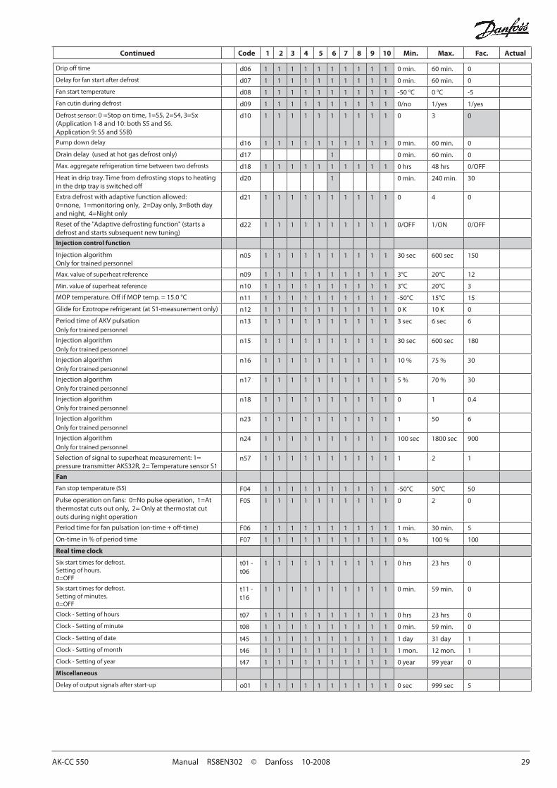
Dripofftime d06 1 1 1 1 1 1 1 1 1 1 0 min. 60min. 0
Delay for fan start after defrost d07 1 1 1 1 1 1 1 1 1 1 0 min. 60min. 0
Fanstarttemperature d08 1 1 1 1 1 1 1 1 1 1 -50 °C 0 °C -5
Fancutinduringdefrost d09 1 1 1 1 1 1 1 1 1 1 0/no 1/yes 1/yes
Defrost sensor:0=Stopontime,1=S5,2=S4,3=Sx(Application1-8and10:bothS5andS6.Application9:S5andS5B)
d10 1 1 1 1 1 1 1 1 1 1 0 3 0
Pumpdowndelay d16 1 1 1 1 1 1 1 1 1 1 0 min. 60min. 0
Draindelay(usedathotgasdefrostonly) d17 1 0 min. 60min. 0
Max. aggregate refrigeration time between two defrosts d18 1 1 1 1 1 1 1 1 1 1 0 hrs 48hrs 0/OFF
Heatindriptray.Timefromdefrostingstopstoheatinginthedriptrayisswitchedoff
d20 1 0 min. 240min. 30
Extradefrostwithadaptivefunctionallowed:0=none,1=monitoringonly,2=Dayonly,3=Bothdayandnight,4=Nightonly
d21 1 1 1 1 1 1 1 1 1 1 0 4 0
Resetofthe"Adaptivedefrostingfunction"(startsadefrostandstartssubsequentnewtuning)
d22 1 1 1 1 1 1 1 1 1 1 0/OFF 1/ON 0/OFF
Injection control function
InjectionalgorithmOnlyfortrainedpersonnel
n05 1 1 1 1 1 1 1 1 1 1 30 sec 600sec 150
Max.valueofsuperheatreference n09 1 1 1 1 1 1 1 1 1 1 3°C 20°C 12
Min.valueofsuperheatreference n10 1 1 1 1 1 1 1 1 1 1 3°C 20°C 3
MOPtemperature.OffifMOPtemp.=15.0°C n11 1 1 1 1 1 1 1 1 1 1 -50°C 15°C 15
GlideforEzotroperefrigerant(atS1-measurementonly) n12 1 1 1 1 1 1 1 1 1 1 0 K 10 K 0
PeriodtimeofAKVpulsationOnlyfortrainedpersonnel
n13 1 1 1 1 1 1 1 1 1 1 3 sec 6sec 6
InjectionalgorithmOnlyfortrainedpersonnel
n15 1 1 1 1 1 1 1 1 1 1 30 sec 600sec 180
InjectionalgorithmOnlyfortrainedpersonnel
n16 1 1 1 1 1 1 1 1 1 1 10% 75% 30
InjectionalgorithmOnlyfortrainedpersonnel
n17 1 1 1 1 1 1 1 1 1 1 5% 70% 30
InjectionalgorithmOnlyfortrainedpersonnel
n18 1 1 1 1 1 1 1 1 1 1 0 1 0.4
InjectionalgorithmOnlyfortrainedpersonnel
n23 1 1 1 1 1 1 1 1 1 1 1 50 6
InjectionalgorithmOnlyfortrainedpersonnel
n24 1 1 1 1 1 1 1 1 1 1 100 sec 1800 sec 900
Selection of signal to superheat measurement: 1= pressure transmitter AKS32R, 2= Temperature sensor S1
n57 1 1 1 1 1 1 1 1 1 1 1 2 1
Fan
Fanstoptemperature(S5) F04 1 1 1 1 1 1 1 1 1 1 -50°C 50°C 50
Pulseoperationonfans:0=Nopulseoperation,1=Atthermostatcutsoutonly,2=Onlyatthermostatcutouts during night operation
F05 1 1 1 1 1 1 1 1 1 1 0 2 0
Periodtimeforfanpulsation(on-time+off-time) F06 1 1 1 1 1 1 1 1 1 1 1 min. 30 min. 5
On-timein%ofperiodtime F07 1 1 1 1 1 1 1 1 1 1 0% 100% 100
Real time clock
Six start times for defrost. Setting of hours. 0=OFF
t01 - t06
1 1 1 1 1 1 1 1 1 1 0 hrs 23 hrs 0
Six start times for defrost.Setting of minutes.0=OFF
t11 - t16
1 1 1 1 1 1 1 1 1 1 0 min. 59 min. 0
Clock-Settingofhours t07 1 1 1 1 1 1 1 1 1 1 0 hrs 23 hrs 0
Clock-Settingofminute t08 1 1 1 1 1 1 1 1 1 1 0 min. 59 min. 0
Clock-Settingofdate t45 1 1 1 1 1 1 1 1 1 1 1 day 31 day 1
Clock-Settingofmonth t46 1 1 1 1 1 1 1 1 1 1 1 mon. 12 mon. 1
Clock-Settingofyear t47 1 1 1 1 1 1 1 1 1 1 0 year 99 year 0
Miscellaneous
Delay of output signals after start-up o01 1 1 1 1 1 1 1 1 1 1 0 sec 999 sec 5
Continued Code 1 2 3 4 5 6 7 8 9 10 Min. Max. Fac. Actual
30 Manual RS8EN302 © Danfoss 10-2008 AK-CC 550
Continued Code 1 2 3 4 5 6 7 8 9 10 Min. Max. Fac. Actual
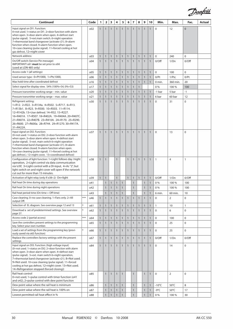
InputsignalonDI1.Function:0=notused.1=statusonDI1.2=doorfunctionwithalarmwhenopen.3=dooralarmwhenopen.4=defroststart(pulse-signal).5=ext.mainswitch.6=nightoperation7=thermostatbandchangeover(activater21).8=alarmfunction when closed. 9=alarm function when open. 10=casecleaning(pulsesignal).11=forcedcoolingathotgas defrost, 12=nightcover
o02 1 1 1 1 1 1 1 1 1 1 0 12 0
Networkaddress o03 1 1 1 1 1 1 1 1 1 1 0 240 0
On/Offswitch(ServicePinmessage)IMPORTANT!o61mustbesetpriortoo04(usedatLON485only)
o04 1 1 1 1 1 1 1 1 1 1 0/Off 1/On 0/Off
Accesscode1(allsettings) o05 1 1 1 1 1 1 1 1 1 1 0 100 0
Usedsensortype:0=Pt1000,1=Ptc1000, o06 1 1 1 1 1 1 1 1 1 1 0/Pt 1/Ptc 0/Pt
Max hold time after coordinated defrost o16 1 1 1 1 1 1 1 1 1 1 0 min. 360min. 20
Selectsignalfordisplayview.S4%(100%=S4,0%=S3) o17 1 1 1 1 1 1 1 1 0% 100% 100
Pressuretransmitterworkingrange–min.value o20 1 1 1 1 1 1 1 1 1 1 -1 bar 5 bar -1
Pressuretransmitterworkingrange–max.value o21 1 1 1 1 1 1 1 1 1 1 6bar 60bar 12
Refrigerant setting:1=R12.2=R22.3=R134a.4=R502.5=R717.6=R13.7=R13b1.8=R23.9=R500.10=R503.11=R114.12=R142b.13=Userdefined.14=R32.15=R227.16=R401A.17=R507.18=R402A.19=R404A.20=R407C.21=R407A.22=R407B.23=R410A.24=R170.25=R290.26=R600.27=R600a.28=R744.29=R1270.30=R417A.31=R422A.
o30 1 1 1 1 1 1 1 1 1 1 0 31 0
InputsignalonDI2.Function: (0=notused.1=statusonDI2.2=doorfunctionwithalarmwhenopen.3=dooralarmwhenopen.4=defroststart(pulse-signal).5=ext.mainswitch6=nightoperation7=thermostatbandchangeover(activater21).8=alarmfunction when closed. 9=alarm function when open. 10=casecleaning(pulsesignal).11=forcedcoolingathotgasdefrost.).12=nightcover,13=coordinateddefrost)
o37 1 1 1 1 1 1 1 1 1 1 0 13 0
Configurationoflightfunction:1=Lightfollowsday/nightoperation,2=Lightcontrolviadatacommunicationvia‘o39’,3=LightcontrolwithaDI-input,4=As"2",butlightswitchonandnightcoverwillopenifthenetworkcut out for more than 15 minutes.
o38 1 1 1 1 1 1 1 1 1 4 1
Activationoflightrelay(onlyifo38=2)On=light o39 1 1 1 1 1 1 1 1 0/Off 1/On 0/Off
RailheatOntimeduringdayoperations o41 1 1 1 1 1 1 1 0% 100% 100
RailheatOntimeduringnightoperations o42 1 1 1 1 1 1 1 0% 100% 100
Railheatperiodtime(Ontime+Offtime) o43 1 1 1 1 1 1 1 6min. 60min. 10
Casecleaning.0=nocasecleaning.1=Fansonly.2=AlloutputOff.
*** o46 1 1 1 1 1 1 1 1 1 1 0 2 0
SelectionofELdiagram.Seeoverviewpage12and13 * o61 1 1 1 1 1 1 1 1 1 1 1 10 1
Downloadasetofpredeterminedsettings.Seeoverviewpage 27.
* o62 1 1 1 1 1 1 1 1 1 1 0 6 0
Accesscode2(partialaccess) *** o64 1 1 1 1 1 1 1 1 1 1 0 100 0
Savethecontrollerspresentsettingstotheprogrammingkey.Selectyourownnumber.
o65 1 1 1 1 1 1 1 1 1 1 0 25 0
Loadasetofsettingsfromtheprogrammingkey(previ-ouslysavedviao65function)
* o66 1 1 1 1 1 1 1 1 1 1 0 25 0
Replace the controllers factory settings with the present settings
o67 1 1 1 1 1 1 1 1 1 1 0/Off 1/On 0/Off
InputsignalonDI3.Function:(highvoltageinput) (0=notused.1=statusonDI2.2=doorfunctionwithalarmwhenopen.3=dooralarmwhenopen.4=defroststart(pulse-signal).5=ext.mainswitch6=nightoperation,7=thermostatbandchangeover(activater21). 8=Not used. 9=Not used. 10=casecleaning(pulsesignal).11=forcedcooling at hot gas defrost, 12=nightcover.13=Notused.14=Refrigerationstopped(forcedclosing))
o84 1 1 1 1 1 1 1 1 1 1 0 14 0
Rail heat control0=notused,1=pulsecontrolwithtimerfunction(o41ando42),2=pulsecontrolwithdewpointfunction
o85 1 1 1 1 1 1 1 0 2 0
Dewpointvaluewheretherailheatisminimum o86 1 1 1 1 1 1 1 -10°C 50°C 8
Dewpointvaluewheretherailheatis100%on o87 1 1 1 1 1 1 1 -9°C 50°C 17
Lowestpermittedrailheateffectin% o88 1 1 1 1 1 1 1 0% 100% 30
AK-CC 550 Manual RS8EN302 © Danfoss 10-2008 31
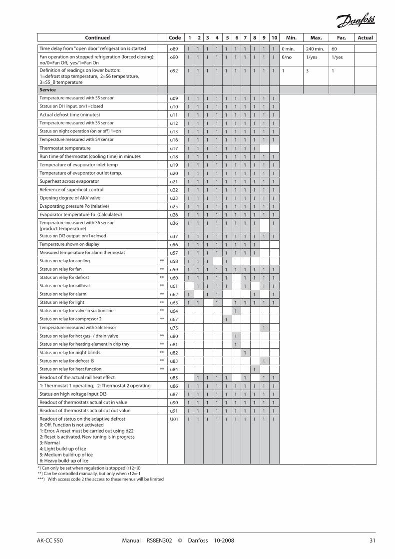
Timedelayfrom"opendoor”refrigerationisstarted o89 1 1 1 1 1 1 1 1 1 1 0 min. 240min. 60
Fanoperationonstoppedrefrigeration(forcedclosing):no/0=FanOff,yes/1=FanOn
o90 1 1 1 1 1 1 1 1 1 1 0/no 1/yes 1/yes
Definitionofreadingsonlowerbutton:1=defroststoptemperature,2=S6temperature,3=S5_Btemperature
o92 1 1 1 1 1 1 1 1 1 1 1 3 1
Service
Temperature measured with S5 sensor u09 1 1 1 1 1 1 1 1 1 1
StatusonDI1input.on/1=closed u10 1 1 1 1 1 1 1 1 1 1
Actualdefrosttime(minutes) u11 1 1 1 1 1 1 1 1 1 1
Temperature measured with S3 sensor u12 1 1 1 1 1 1 1 1 1 1
Statusonnightoperation(onoroff)1=on u13 1 1 1 1 1 1 1 1 1 1
TemperaturemeasuredwithS4sensor u16 1 1 1 1 1 1 1 1 1 1
Thermostat temperature u17 1 1 1 1 1 1 1 1
Runtimeofthermostat(coolingtime)inminutes u18 1 1 1 1 1 1 1 1 1 1
Temperatureofevaporatorinlettemp u19 1 1 1 1 1 1 1 1 1 1
Temperatureofevaporatoroutlettemp. u20 1 1 1 1 1 1 1 1 1 1
Superheatacrossevaporator u21 1 1 1 1 1 1 1 1 1 1
Reference of superheat control u22 1 1 1 1 1 1 1 1 1 1
OpeningdegreeofAKVvalve u23 1 1 1 1 1 1 1 1 1 1
EvaporatingpressurePo(relative) u25 1 1 1 1 1 1 1 1 1 1
EvaporatortemperatureTo(Calculated) u26 1 1 1 1 1 1 1 1 1 1
TemperaturemeasuredwithS6sensor(producttemperature)
u36 1 1 1 1 1 1 1 1 1
StatusonDI2output.on/1=closed u37 1 1 1 1 1 1 1 1 1 1
Temperature shown on display u56 1 1 1 1 1 1 1 1
Measured temperature for alarm thermostat u57 1 1 1 1 1 1 1 1
Status on relay for cooling ** u58 1 1 1 1
Status on relay for fan ** u59 1 1 1 1 1 1 1 1 1 1
Status on relay for defrost ** u60 1 1 1 1 1 1 1 1 1
Status on relay for railheat ** u61 1 1 1 1 1 1 1
Status on relay for alarm ** u62 1 1 1 1 1
Status on relay for light ** u63 1 1 1 1 1 1 1 1
Statusonrelayforvalveinsuctionline ** u64 1
Status on relay for compressor 2 ** u67 1
TemperaturemeasuredwithS5Bsensor u75 1
Status on relay for hotgas-/drainvalve ** u80 1
Status on relay for heating element in drip tray ** u81 1
Status on relay for night blinds ** u82 1
Status on relay for defrost B ** u83 1
Status on relay for heat function ** u84 1
Readoutoftheactualrailheateffect u85 1 1 1 1 1 1 1
1: Thermostat 1 operating, 2: Thermostat 2 operating u86 1 1 1 1 1 1 1 1 1 1
StatusonhighvoltageinputDI3 u87 1 1 1 1 1 1 1 1 1 1
Readoutofthermostatsactualcutinvalue u90 1 1 1 1 1 1 1 1 1 1
Readoutofthermostatsactualcutoutvalue u91 1 1 1 1 1 1 1 1 1 1
Readoutofstatusontheadaptivedefrost0:Off.Functionisnotactivated1: Error. A reset must be carried out using d222:Resetisactivated.Newtuningisinprogress3: Normal4:Lightbuild-upofice5: Medium build-up of ice6:Heavybuild-upofice
U01 1 1 1 1 1 1 1 1 1 1
Continued Code 1 2 3 4 5 6 7 8 9 10 Min. Max. Fac. Actual
*)Canonlybesetwhenregulationisstopped(r12=0)**)Canbecontrolledmanually,butonlywhenr12=-1***) Withaccesscode2theaccesstothesemenuswillbelimited

32 Manual RS8EN302 © Danfoss 10-2008 AK-CC 550
DI1Digital input signal. Thedefinedfunctionisactivewhentheinputisshort-circuited/opened.Thefunctionisdefinedino02.
DI2Digital input signal. Thedefinedfunctionisactivewhentheinputisshort-circuited/opened.Thefunctionisdefinedino37.
Pressure transmitter or temperature sensor S1Pe / AKS 32R (pressure measurement recommended)
Connect to terminal 30, 31 and 32.Thesignalfromonepressuretransmittercanbereceivedbyupto10controllers.Butonlyiftherearenosignificantpressuredecreasesbetweentheevaporatorstobecontrolled.
S1 (correct location is important to ensure correct measurements)Pt1000ohmsensorConnect to terminal 31 and 32.
S2Pt1000ohmsensor
S3, S4, S5, S6Pt1000ohmsensororPTC1000ohmsensor.Allhavetobeofthe same type.
S3, air sensor, placed in the warm air before the evaporatorS4, air sensor, placed in the cold air after the evaporator
(theneedforeitherS3orS4canbedeselectedintheconfiguration)
S5, defrost sensor, placed on the evaporatorS6, product sensor or defrost sensor B or air sensor B.
Theconfigurationdetermineswhich.
EKA DisplayIfthereisbeexternalreading/operationofthecontroller,displaytypeEKA163BorEKA164Bcanbeconnected.
RS485 (terminal 51, 52, 53)Fordatacommunication,butonlyifadatacommunicationmoduleisinsertedinthecontroller.ThemodulecanbeaLONRS485oraMODBUS.Terminal 51 = screenTerminal52=A(A+)Terminal53=B(B-)(ForLONRS485andgatewaytypeAKA245thegatewaymustbeversion6.20orhigher.)
RJ45Fordatacommunication,butonlyifaTCP/IPmoduleisinsertedinthecontroller.(OEMspecific)
MODBUSFordatacommunication.Terminal56=screenTerminal 57 = A+Terminal58=B-(AlternativelytheterminalscanbeconnectedtoanexternaldisplaytypeEKA163Aor164A,butthentheycannotbeusedfor data communication. Any data communication must then be carriedoutbyoneoftheothermethods.)
Supply voltage230 V a.c.
Connections Version where sensor connectionshaveplugconnections.
Overview of outputs and applications.
See also electrical diagrams earlier in the manual
Application DO1 DO2 DO3 DO4 DO5 DO6 DI1 DI2 DI3 AI1 AI2 AI3 AI4 AI5 AI6
1 • • • P0/S1 S2 S3 S4 S5 S6
2 • • • P0/S1 S2 S3 S4 S5 S6
3 • • • P0/S1 S2 S3 S4 S5 S6
4 • • • P0/S1 S2 S3 S4 S5 S6
5 • • • P0/S1 S2 S3 S4 S5 S6
6 suction
hotgas • • • P0/S1 S2 S3 S4 S5 S6
7 Blinds • • • P0/S1 S2 S3 S4 S5 S6
8 heat • • • P0/S1 S2 S3 S4 S5 S6
9 2 1 • • • P0/S1 S2 S3 S4 S5 S5B
10 • • • P0/S1 S2 S3 S4 S5 S3B
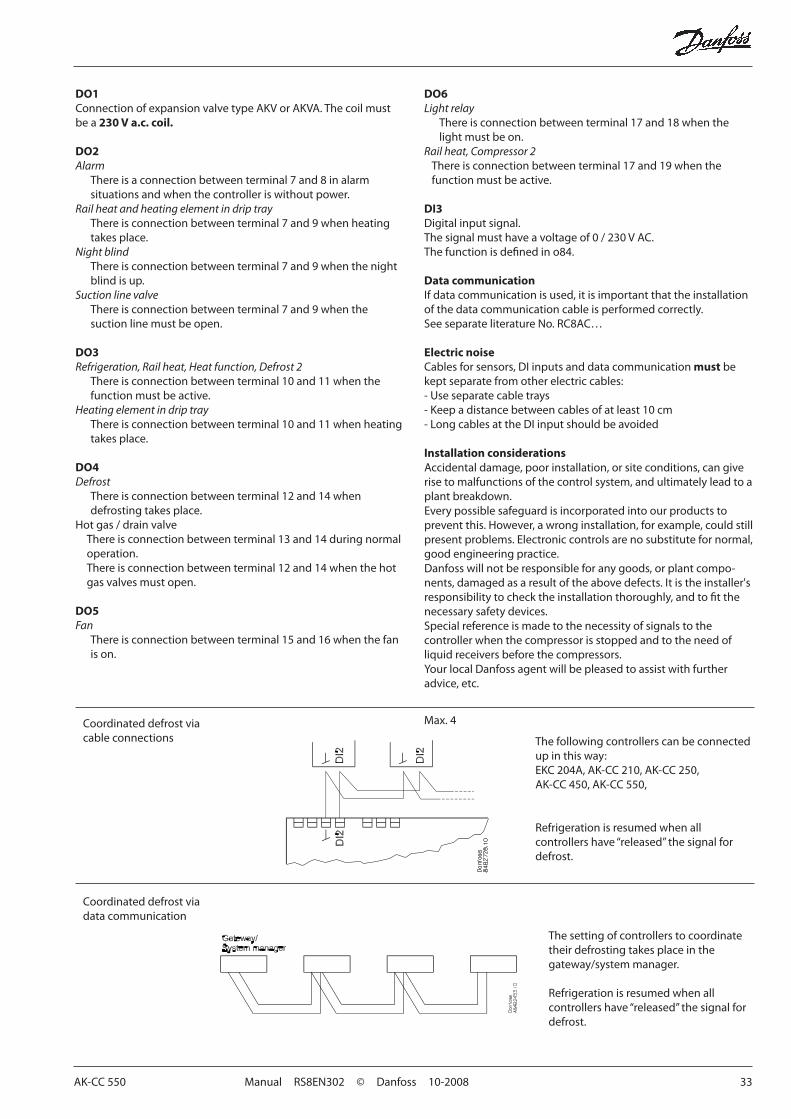
AK-CC 550 Manual RS8EN302 © Danfoss 10-2008 33
Coordinateddefrostviadata communication
Coordinateddefrostviacable connections The following controllers can be connected
up in this way:EKC204A,AK-CC210,AK-CC250,AK-CC450,AK-CC550,
Refrigeration is resumed when all controllershave“released”thesignalfordefrost.
The setting of controllers to coordinate theirdefrostingtakesplaceinthegateway/systemmanager.
Refrigeration is resumed when all controllershave“released”thesignalfordefrost.
DO1ConnectionofexpansionvalvetypeAKVorAKVA.Thecoilmustbe a 230 V a.c. coil.
DO2Alarm
There is a connection between terminal 7 and 8 in alarm situations and when the controller is without power.
Rail heat and heating element in drip trayThere is connection between terminal 7 and 9 when heating takesplace.
Night blindThere is connection between terminal 7 and 9 when the night blind is up.
Suction line valveThere is connection between terminal 7 and 9 when the suction line must be open.
DO3Refrigeration, Rail heat, Heat function, Defrost 2
There is connection between terminal 10 and 11 when the functionmustbeactive.
Heating element in drip trayThere is connection between terminal 10 and 11 when heating takesplace.
DO4Defrost
Thereisconnectionbetweenterminal12and14whendefrostingtakesplace.
Hotgas/drainvalveThereisconnectionbetweenterminal13and14duringnormaloperation. Thereisconnectionbetweenterminal12and14whenthehotgasvalvesmustopen.
DO5Fan
Thereisconnectionbetweenterminal15and16whenthefanis on.
DO6Light relay
There is connection between terminal 17 and 18 when the light must be on.
Rail heat, Compressor 2There is connection between terminal 17 and 19 when the functionmustbeactive.
DI3Digital input signal. Thesignalmusthaveavoltageof0/230VAC.Thefunctionisdefinedino84.
Data communicationIfdatacommunicationisused,itisimportantthattheinstallationof the data communication cable is performed correctly.See separate literature No. RC8AC…
Electric noiseCablesforsensors,DIinputsanddatacommunicationmust be keptseparatefromotherelectriccables:-Useseparatecabletrays- Keep a distance between cables of at least 10 cm-LongcablesattheDIinputshouldbeavoided
Installation considerationsAccidentaldamage,poorinstallation,orsiteconditions,cangiverise to malfunctions of the control system, and ultimately lead to a plantbreakdown.Everypossiblesafeguardisincorporatedintoourproductstopreventthis.However,awronginstallation,forexample,couldstillpresent problems. Electronic controls are no substitute for normal, good engineering practice.Danfoss will not be responsible for any goods, or plant compo-nents,damagedasaresultoftheabovedefects.Itistheinstaller'sresponsibilitytochecktheinstallationthoroughly,andtofitthenecessarysafetydevices.Special reference is made to the necessity of signals to the controller when the compressor is stopped and to the need of liquidreceiversbeforethecompressors.YourlocalDanfossagentwillbepleasedtoassistwithfurtheradvice,etc.
Max.4

34 Manual RS8EN302 © Danfoss 10-2008 AK-CC 550
DataSupplyvoltage 230Va.c.+10/-15%.5VA,50/60Hz
SensorS2,(S1) Pt1000
SensorS3,S4,S5,S6
Pt1000orPTC1000ohm/25°C(All4mustbeofthesametype)
Accuracy
Measuring range -60to+120°C
Controller ±1 K below -35°C±0.5 K between -35 to +25°C ±1Kabove+25°C
Pt1000sensor±0.3 K at 0°C±0.005 K per grad
MeasuringofPePressure transmitter
AKS 32R
Display LED,3-digits
External display EKA163Bor164B.(anyEKA163Aor164A)
Digital inputs DI1,DI2
Signal from contact functionsRequirementstocontacts:GoldplatingCable length must be max. 15 mUseauxiliaryrelayswhenthecableislonger
DigitalinputDI3 230 V a.c.
Electrical con-nection cable
Max.1.5 mm2 multi-core cable
Solid state output
DO1(forAKVcoil)
Max.240Va.c.,Min.28Va.c.Max. 0.5 ALeak<1mAMax. 1 pcs. AKV
Relays*
CE (250Va.c.)
DO3,DO4 4(3)A
DO2,DO5,DO6 4(3)A
Environments
0 to +55°C, During operations-40to+70°C,Duringtransport
20-80%Rh,notcondensed
Noshockinfluence/vibrations
Density IP20
Mounting DIN-railorwall
Weight 0.4Kg
Data communication
Fixed MODBUS
Extension options
LONRS485
TCP/IP
MODBUS
Thecontrollercannotbehookedupwithamonitor-ing unit type m2.
Powerreservefortheclock
4hours
Approvals
EULowVoltageDirectiveandEMCdemandsreCE-markingcompliedwithLVDtestedacc.EN60730-1andEN60730-2-9,A1,A2EMCtestedacc.EN50082-1andEN60730-2-9,A2
*DO3andDO4are16Arelays.DO2,DO5andDO6are8Arelays.Max.loadmustbeobserved.
AKV info !!
230 V a.c. coil
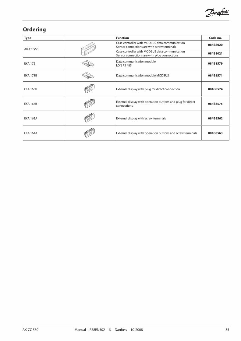
AK-CC 550 Manual RS8EN302 © Danfoss 10-2008 35
OrderingType Function Code no.
AK-CC 550
CasecontrollerwithMODBUSdatacommunicationSensor connections are with screw terminals
084B8020
CasecontrollerwithMODBUSdatacommunicationSensor connections are with plug connections
084B8021
EKA 175Data communication moduleLONRS485
084B8579
EKA178B DatacommunicationmoduleMODBUS 084B8571
EKA163B External display with plug for direct connection 084B8574
EKA164BExternal display with operation buttons and plug for direct connections
084B8575
EKA163A External display with screw terminals 084B8562
EKA164A External display with operation buttons and screw terminals 084B8563

36 Manual RS8EN302 © Danfoss 10-2008 AK-CC 550
DE-DBDanfosscanacceptnoresponsibilityforpossibleerrorsincatalogues,brochuresandotherprintedmaterial.Danfossreservestherighttoalteritsproductswithoutnotice.Thisalsoappliestoproducts
alreadyonorderprovidedthatsuchalternationscanbemadewithoutsubsequentialchangesbeingnecessaryinspecificationsalreadyagreed.Alltrademarksinthismaterialarepropertyoftherespecitvecompanies.DanfossandDanfosslogotypearetrademarksofDanfossA/S.Allrightsreserved.