Embed Size (px)
Citation preview
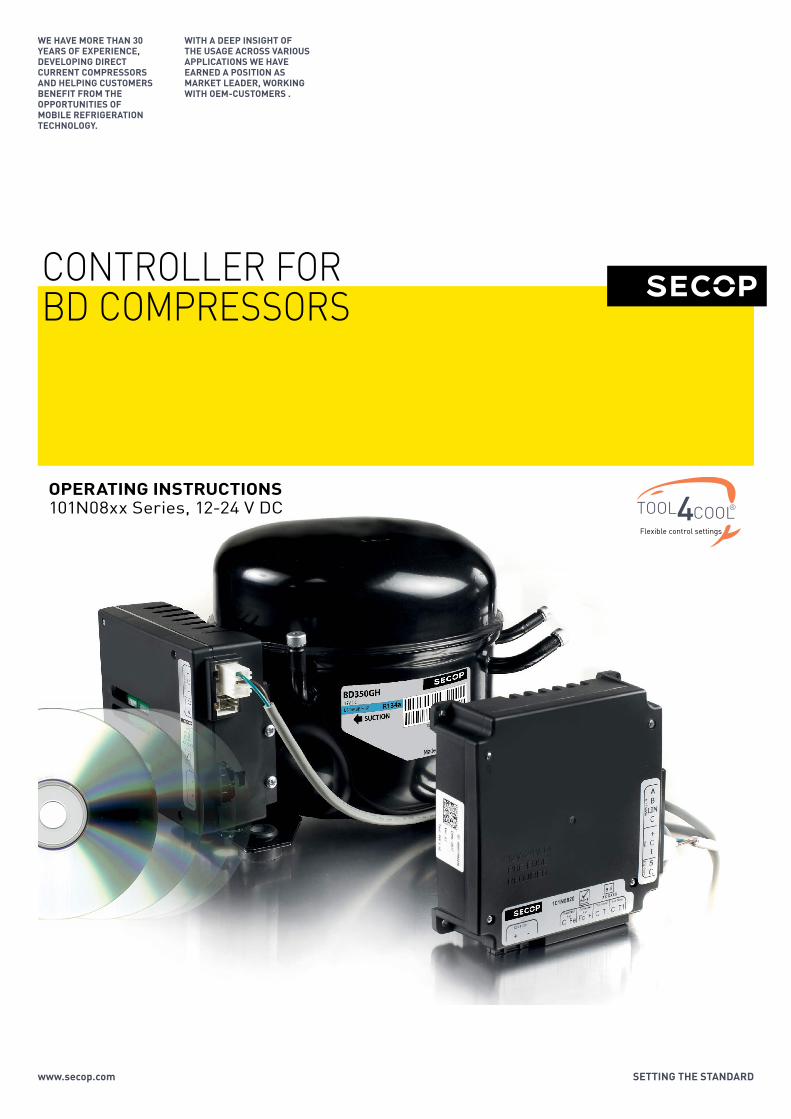
CONTROLLER FORBD COMPRESSORS
Flexible control settings
TOOL COOL4OPERATING INSTRUCTIONS101N08xx Series, 12-24 V DC
WE HAVE MORE THAN 30 YEARS OF EXPERIENCE, DEVELOPING DIRECT CURRENT COMPRESSORS AND HELPING CUSTOMERS BENEFIT FROM THE OPPORTUNITIES OF MOBILE REFRIGERATION TECHNOLOGY.
WITH A DEEP INSIGHT OF THE USAGE ACROSS VARIOUS APPLICATIONS WE HAVE EARNED A POSITION AS MARKET LEADER, WORKING WITH OEM-CUSTOMERS .
www.secop.com SETTING THE STANDARD
2
OperatingInstructions
TABLE OF CONTENTS
1. Introduction.............................................................................................. 3 1.1 Applications ...............................................................................................3 1.2 Capability ...................................................................................................3 1.3 Functions ...................................................................................................3 1.4 Programming Interface .............................................................................3
2. Installation .............................................................................................. 4 2.1 Checklist ....................................................................................................4 2.2 Connect Cables .........................................................................................5 2.3 Install and Configure Software ...............................................................11
3. TOOL4COOL®SoftwareInterface............................................................. 27 3.1 User Interface ..........................................................................................27 3.2 Operation .................................................................................................27
4. Parameters ............................................................................................ 28 4.1 Parameter Overview ................................................................................28 4.2 Description of Parameters ......................................................................36 4.3 Error and Event Logs ..............................................................................46
5. Ordering ............................................................................................ 47
3
OperatingInstructions
The Secop BD compressors with 101N08xx Series 12-24V DC are designed for use in:• Comfort cooling in parking anti-idle applications• Spot and comfort cooling in buses, golf carts, smaller boats, forklifts, campers etc• Cooling of switchboards and batteries in radio stations for cellular phones• Mobile refrigeration applications• Air cargo cooling• Mobile cooling boxes of volume up to 1000L • Mobile refrigeration applications
For R134a compressor variants:One application module can control either single or twin compressor configurations. The cooling capacity of the single compressor configuration is approx. 900 Watt @ Pe/Pc ~+15/+55°C The cooling capacity of the twin compressor configuration is approx. 1800 Watt @ Pe/Pc ~+15/+55°C The system is able to operate in ambient temperatures up to +55 ºC.The operating conditions are High Back Pressure (HBP).
For R404A/R507 compressor variants:The cooling capacity of the compressor is approx. 380 Watt @ Pe/Pc ~-5/+55°CThe system is able to operate in ambient temperatures up to +55 ºC.The operating conditions are Low Back Pressure (LBP).
The main functions of the controllers are:• Operation using either 12 V DC or 24 V DC• Simultaneous and independent control of two compressors in twin configuration • ECO function to optimize compressor speed for minimum power consumption• Detailed error log• Event log • Motor / Compressor speed control• Thermostat control (ON / OFF or electronic via NTC temperature sensor)• Condenser fan control• Evaporator fan control• Communication interface• Monitoring function• Battery protection functions• Main Switch• Log of specific parameters• Optimization of specific parameters via PC software before commencing mass production
The controller can be accessed using either• The Secop software tool Tool4Cool® LabEdition, or• A custom interface. Please contact Secop for further information regarding custom interfaces
1.INTRODUCTION
1.1Applications
1.2Capability
1.3Functions
1.4Programming Interface
4
OperatingInstructions
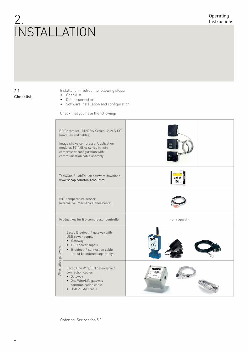
Installation involves the following steps:• Checklist• Cable connection• Software installation and configuration
Ordering: See section 5.0
BD Controller 101N08xx Series 12-24 V DC (modules and cables)
Image shows compressor/application modules 101N08xx-series in twin compressor configuration with communication cable asembly
Tool4Cool® LabEdition software download:www.secop.com/tool4cool.html
NTC temperature sensor (alternative: mechanical thermostat)
Product key for BD compressor controller - on request -
Alte
rnat
ive
gate
way
s
Secop Bluetooth® gateway with USB power supply• Gateway• USB power supply• Bluetooth® connection cable (must be ordered separately)
Secop One Wire/LIN gateway with connection cables• Gateway• One Wire/LIN gateway communication cable• USB 2.0 A/B cable
Check that you have the following:
2.1Checklist
2.INSTALLATION
5
OperatingInstructions
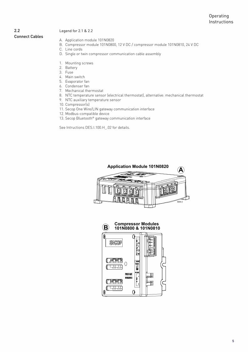
Legend for 2.1 & 2.2
A. Application module 101N0820 B. Compressor module 101N0800, 12 V DC / compressor module 101N0810, 24 V DCC. Line cordsD. Single or twin compressor communication cable assembly
1. Mounting screws2. Battery3. Fuse4. Main switch5. Evaporator fan6. Condenser fan7. Mechanical thermostat8. NTC temperature sensor (electrical thermostat), alternative: mechanical thermostat 9. NTC auxiliary temperature sensor10. Compressor(s)11. Secop One Wire/LIN gateway communication interface12. Modbus-compatible device13. Secop Bluetooth® gateway communication interface
See Intructions DES.I.100.H_.02 for details.
2.2ConnectCables
6
OperatingInstructions
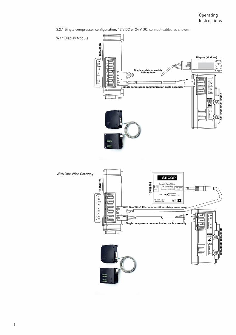
2.2.1 Single compressor configuration, 12 V DC or 24 V DC, connect cables as shown:
With Display Module
With One Wire Gateway
7
OperatingInstructions
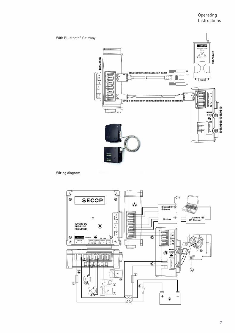
Wiring diagram
With Bluetooth® Gateway
8
OperatingInstructions
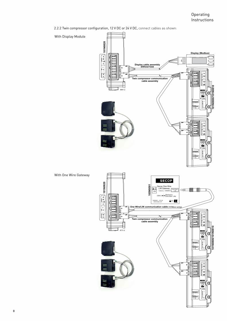
2.2.2 Twin compressor configuration, 12 V DC or 24 V DC, connect cables as shown:
With Display Module
With One Wire Gateway
9
OperatingInstructions
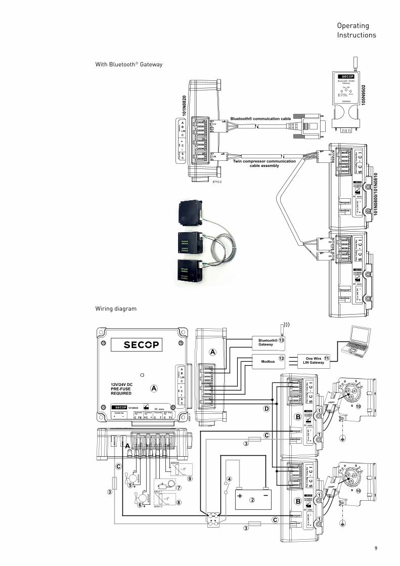
Wiring diagram
With Bluetooth® Gateway
10
OperatingInstructions
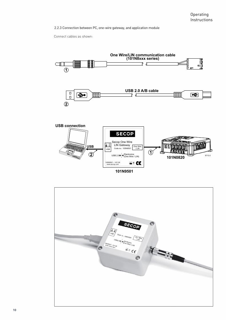
2.2.3 Connection between PC, one-wire gateway, and application module
Connect cables as shown:
11
OperatingInstructions
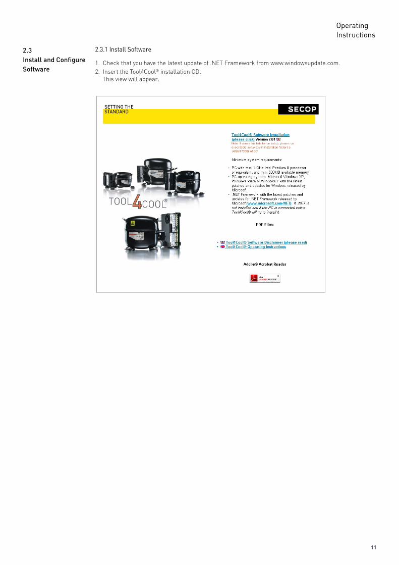
2.3.1 Install Software2.3InstallandConfigureSoftware
1. Check that you have the latest update of .NET Framework from www.windowsupdate.com.2. Insert the Tool4Cool® installation CD. This view will appear:
12
OperatingInstructions
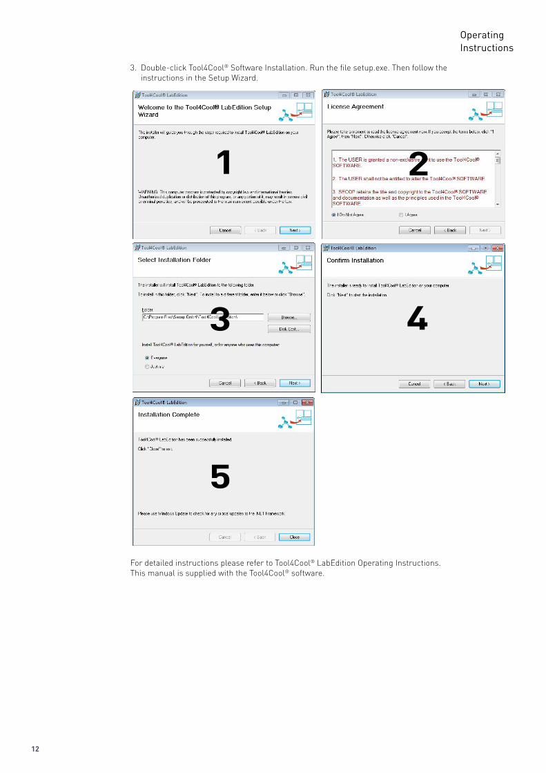
3. Double-click Tool4Cool® Software Installation. Run the file setup.exe. Then follow the instructions in the Setup Wizard.
For detailed instructions please refer to Tool4Cool® LabEdition Operating Instructions.This manual is supplied with the Tool4Cool® software.
1 2
3 4
5
13
OperatingInstructions
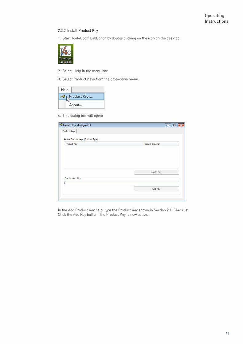
2.3.2 Install Product Key
4. This dialog box will open:
In the Add Product Key field, type the Product Key shown in Section 2.1: Checklist. Click the Add Key button. The Product Key is now active.
1. Start Tool4Cool® LabEditon by double clicking on the icon on the desktop:
2. Select Help in the menu bar.
3. Select Product Keys from the drop-down menu:
14
OperatingInstructions
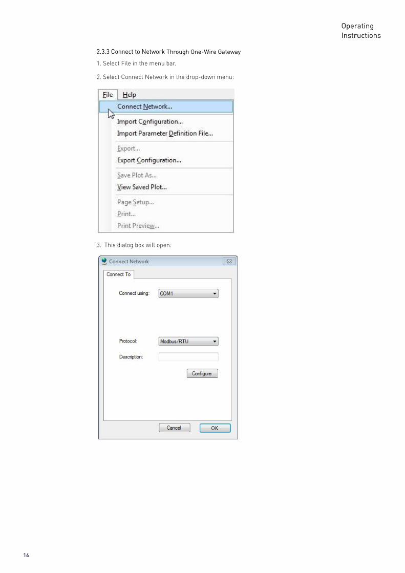
2.3.3 Connect to Network Through One-Wire Gateway
3. This dialog box will open:
1. Select File in the menu bar.
2. Select Connect Network in the drop-down menu:
15
OperatingInstructions
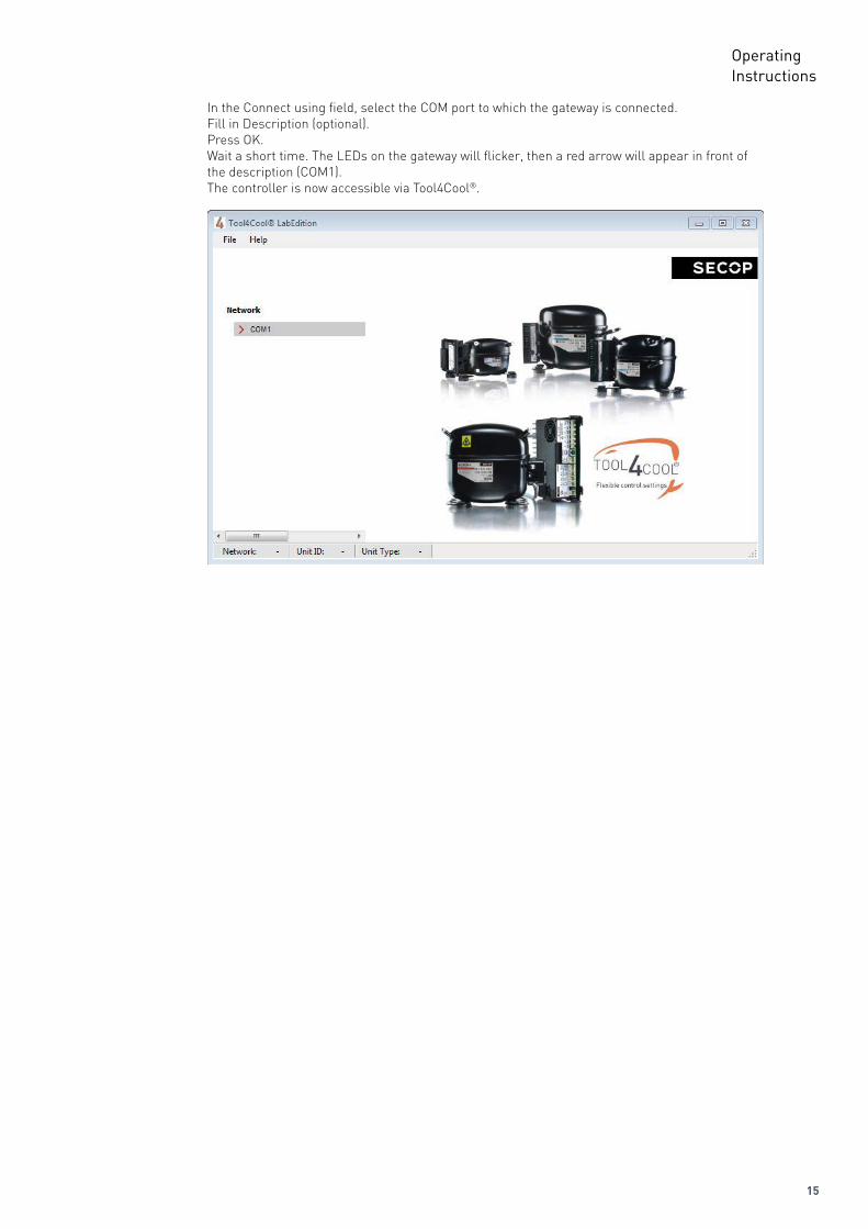
In the Connect using field, select the COM port to which the gateway is connected.Fill in Description (optional).Press OK.Wait a short time. The LEDs on the gateway will flicker, then a red arrow will appear in front of the description (COM1). The controller is now accessible via Tool4Cool®.
16
OperatingInstructions
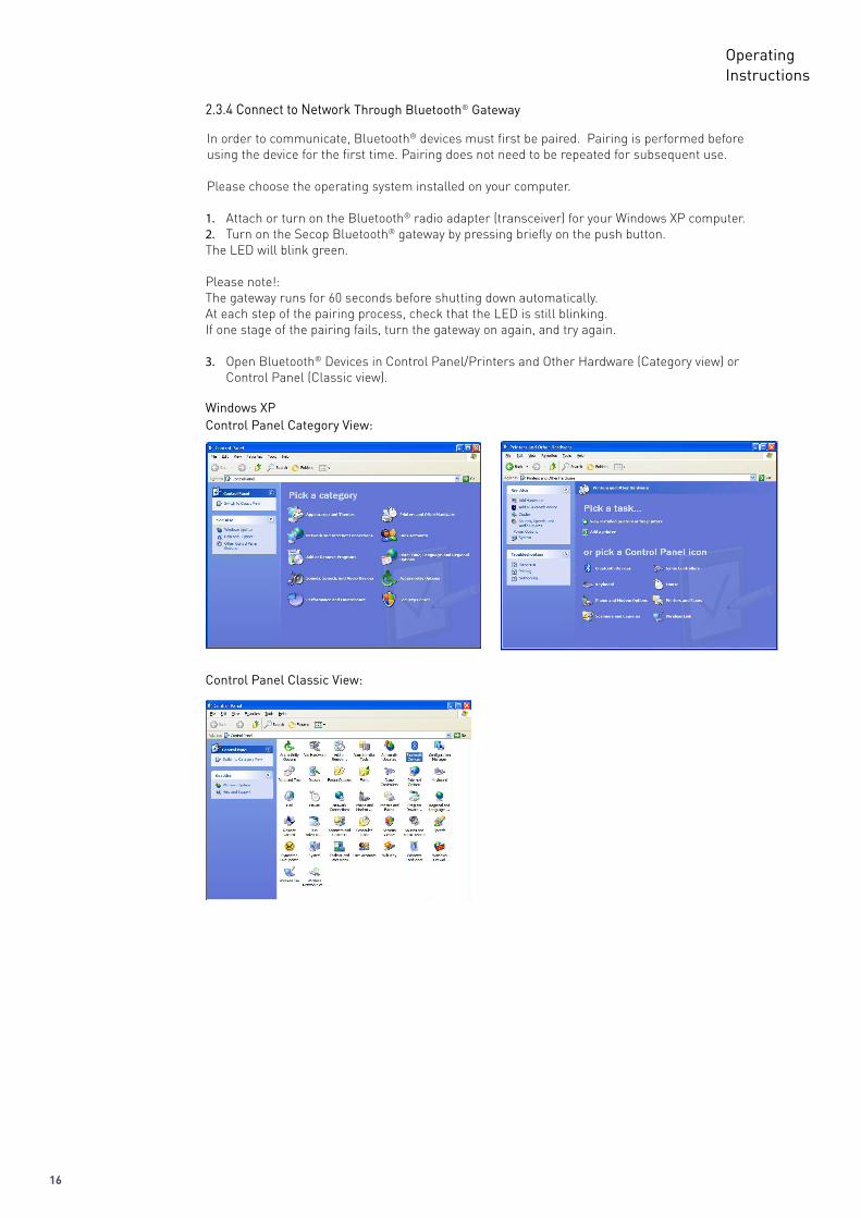
2.3.4 Connect to Network Through Bluetooth® Gateway
1. Attach or turn on the Bluetooth® radio adapter (transceiver) for your Windows XP computer. 2. Turn on the Secop Bluetooth® gateway by pressing briefly on the push button. The LED will blink green.
Please note!: The gateway runs for 60 seconds before shutting down automatically. At each step of the pairing process, check that the LED is still blinking. If one stage of the pairing fails, turn the gateway on again, and try again.
3. Open Bluetooth® Devices in Control Panel/Printers and Other Hardware (Category view) or Control Panel (Classic view).
Windows XPControl Panel Category View:
Control Panel Classic View:
In order to communicate, Bluetooth® devices must first be paired. Pairing is performed before using the device for the first time. Pairing does not need to be repeated for subsequent use.
Please choose the operating system installed on your computer.
17
OperatingInstructions
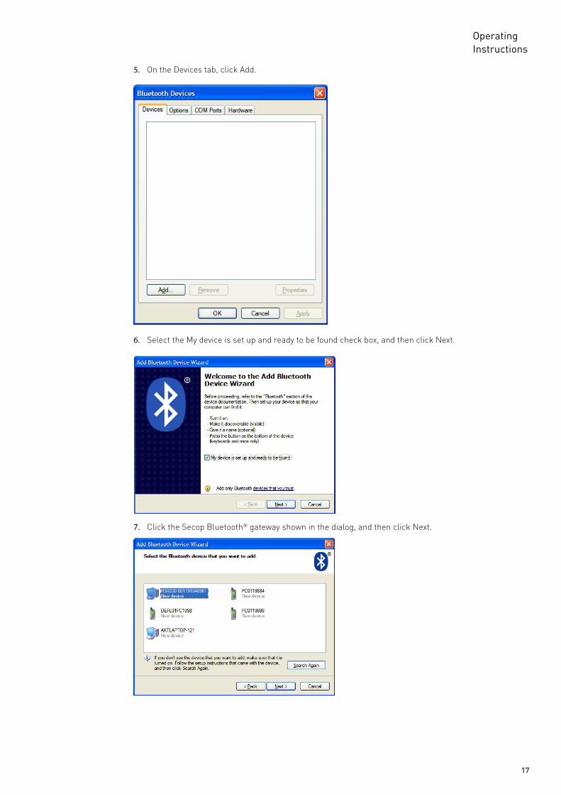
5. On the Devices tab, click Add.
6. Select the My device is set up and ready to be found check box, and then click Next.
7. Click the Secop Bluetooth® gateway shown in the dialog, and then click Next.
18
OperatingInstructions
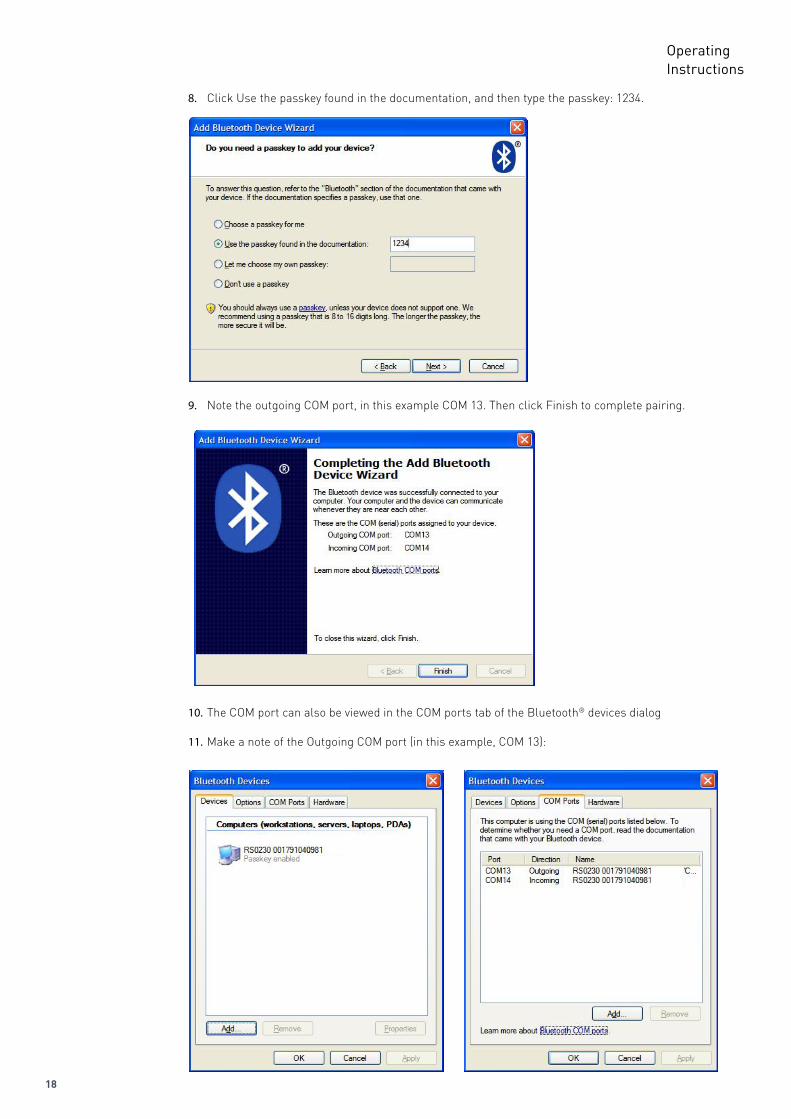
8. Click Use the passkey found in the documentation, and then type the passkey: 1234.
9. Note the outgoing COM port, in this example COM 13. Then click Finish to complete pairing.
10. The COM port can also be viewed in the COM ports tab of the Bluetooth® devices dialog
11. Make a note of the Outgoing COM port (in this example, COM 13):
19
OperatingInstructions
1. Attach or turn on the Bluetooth® radio adapter (transceiver) for your Windows 7 computer.
2. Turn the Secop Bluetooth® gateway on by pressing briefly on the push button. The LED will blink green.
Please note:The gateway runs for 60 seconds before shutting down automatically.At each step of the pairing process, check that the LED is still blinking .If one stage of the pairing fails, turn the gateway on again, and try again.
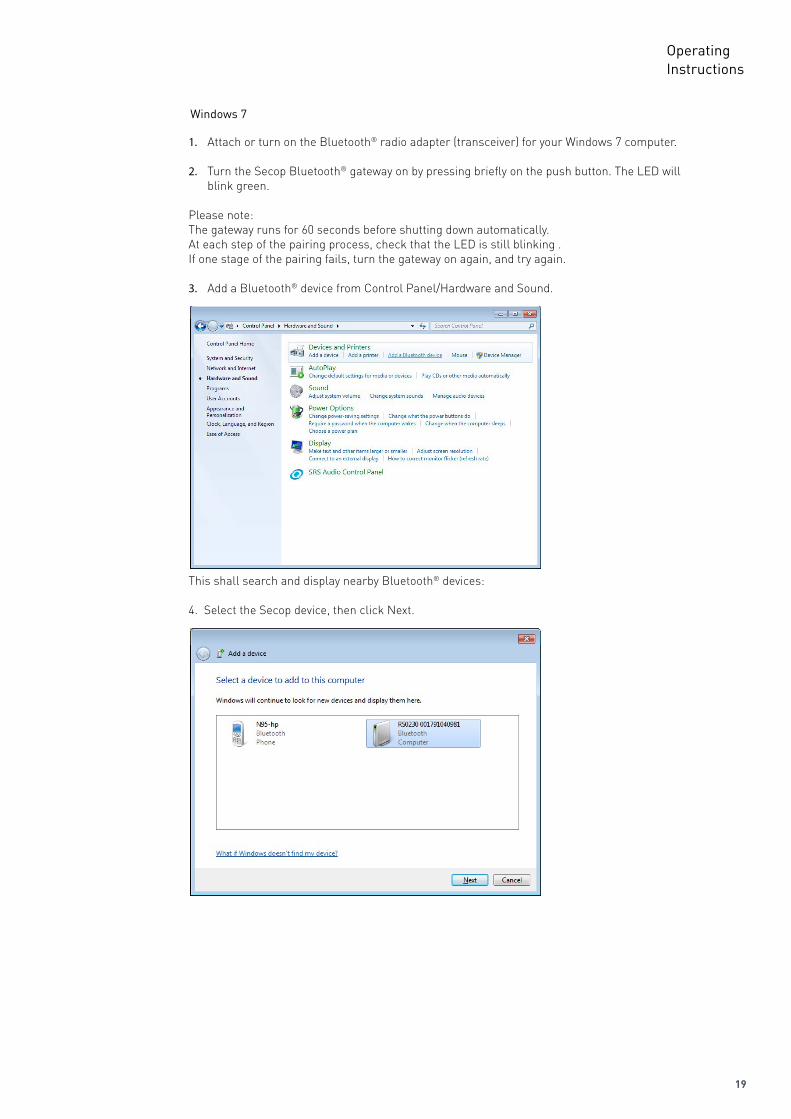
3. Add a Bluetooth® device from Control Panel/Hardware and Sound.
This shall search and display nearby Bluetooth® devices:
4. Select the Secop device, then click Next.
Windows 7
20
OperatingInstructions
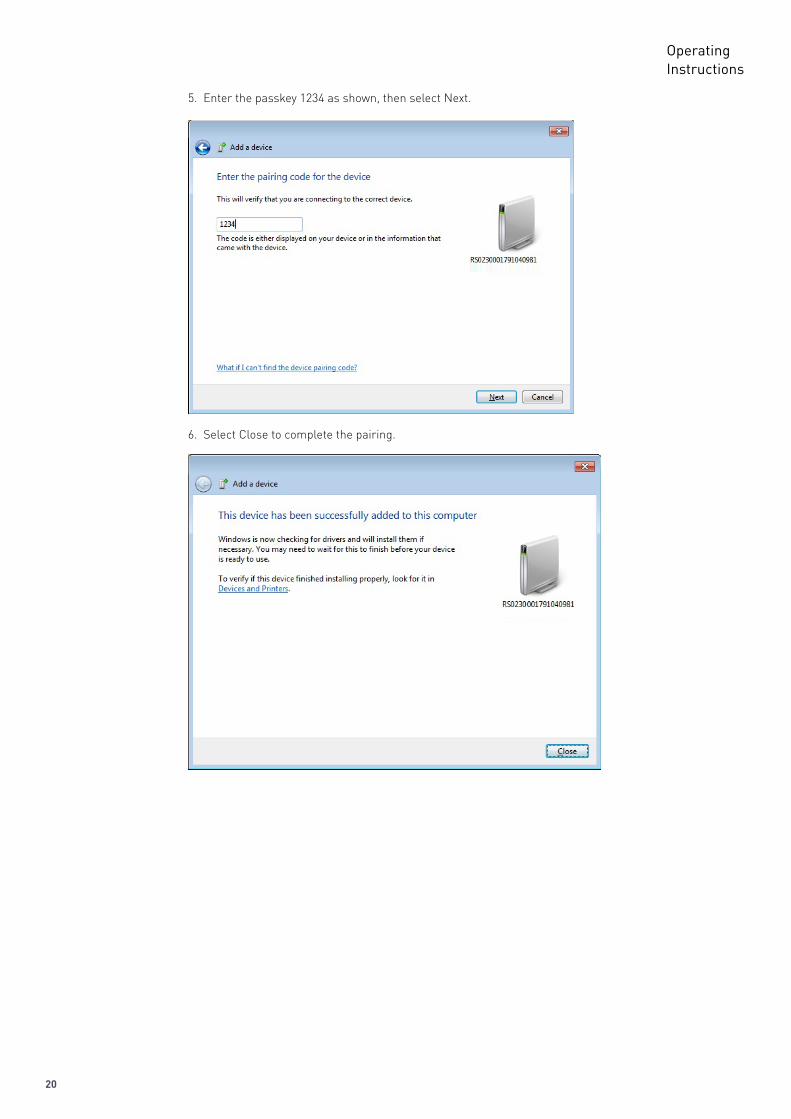
5. Enter the passkey 1234 as shown, then select Next.
6. Select Close to complete the pairing.
21
OperatingInstructions
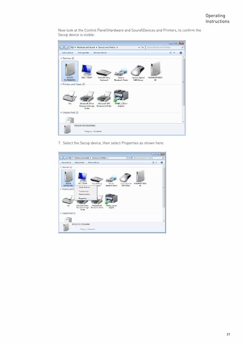
Now look at the Control Panel\Hardware and Sound\Devices and Printers, to confirm the Secop device is visible:
7. Select the Secop device, then select Properties as shown here:
22
OperatingInstructions
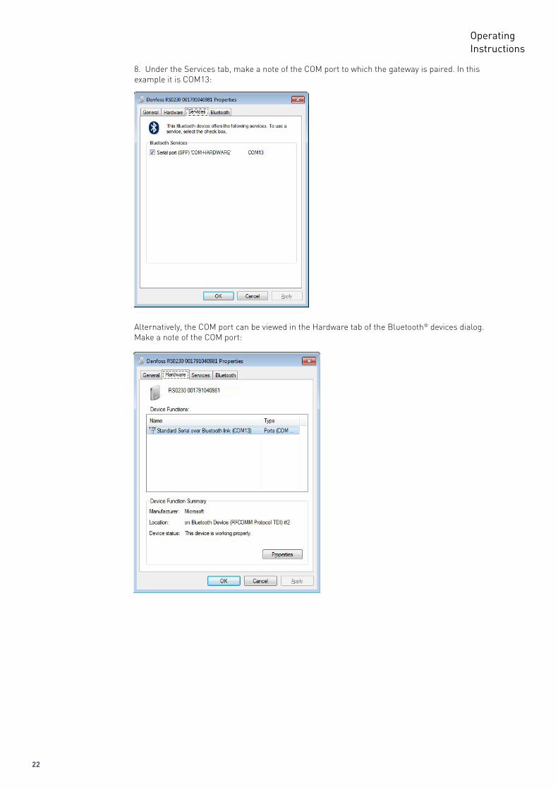
8. Under the Services tab, make a note of the COM port to which the gateway is paired. In this example it is COM13:
Alternatively, the COM port can be viewed in the Hardware tab of the Bluetooth® devices dialog.Make a note of the COM port:
23
OperatingInstructions
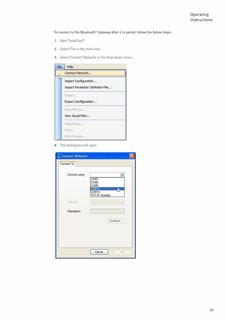
To connect to the Bluetooth® Gateway after it is paired, follow the below steps:
1. Start Tool4Cool®
2. Select File in the menu bar.
3. Select Connect Network in the drop-down menu:
4. This dialog box will open:
24
OperatingInstructions
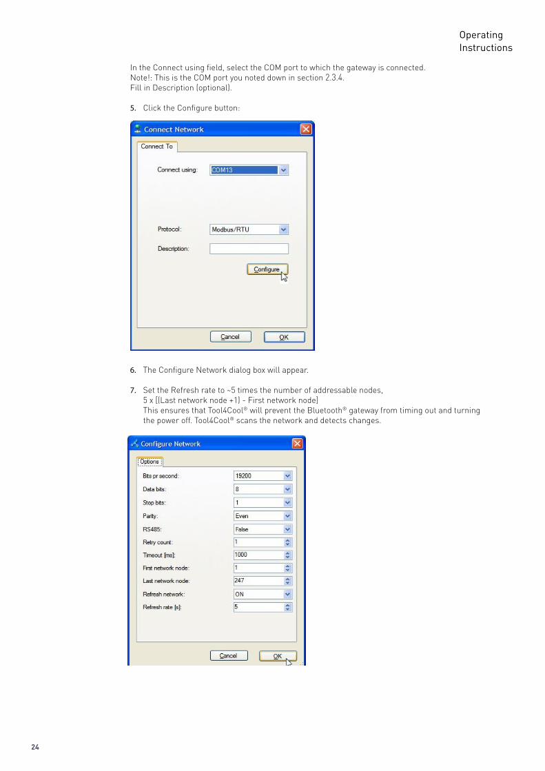
In the Connect using field, select the COM port to which the gateway is connected.Note!: This is the COM port you noted down in section 2.3.4. Fill in Description (optional).
5. Click the Configure button:
6. The Configure Network dialog box will appear.
7. Set the Refresh rate to ~5 times the number of addressable nodes, 5 x [(Last network node +1) - First network node]This ensures that Tool4Cool® will prevent the Bluetooth® gateway from timing out and turning the power off. Tool4Cool® scans the network and detects changes.
25
OperatingInstructions
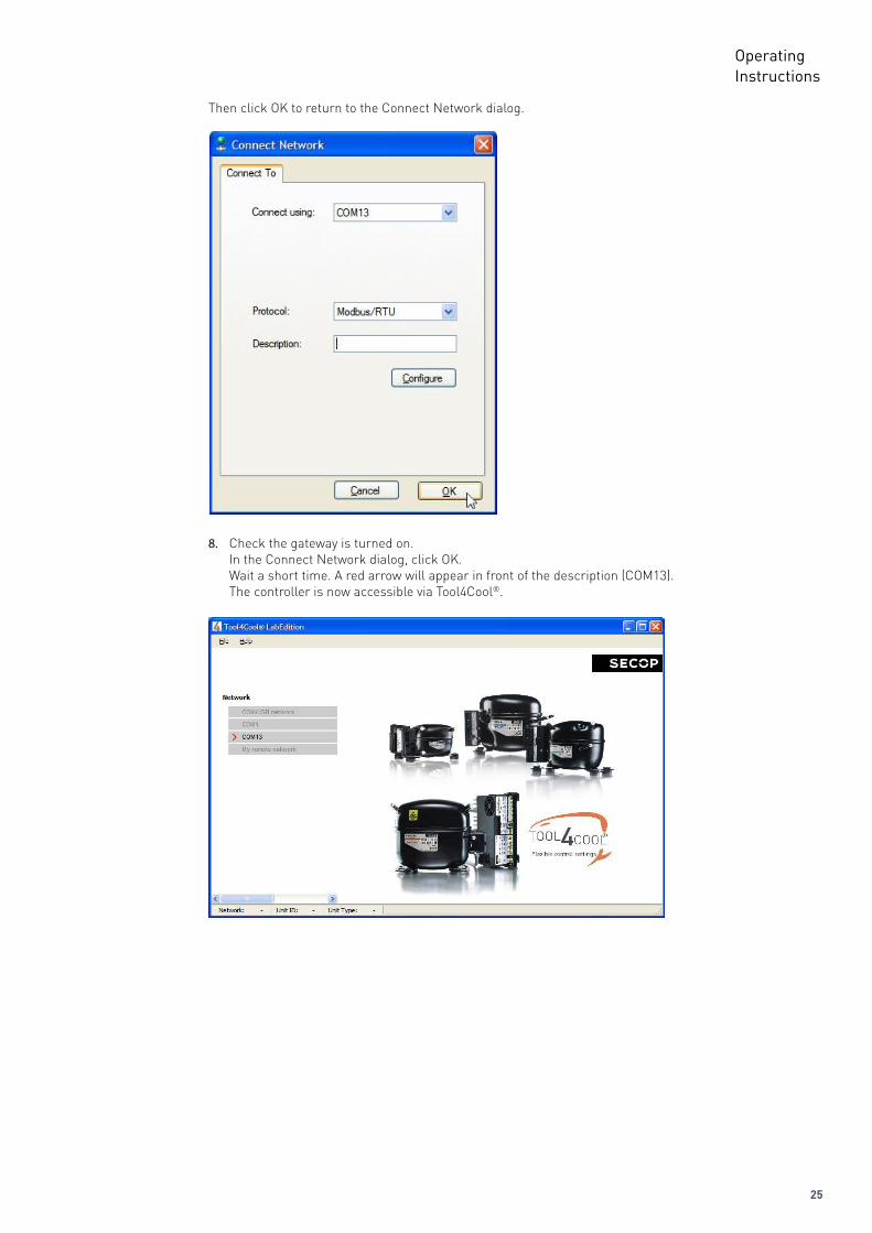
Then click OK to return to the Connect Network dialog.
8. Check the gateway is turned on.In the Connect Network dialog, click OK. Wait a short time. A red arrow will appear in front of the description (COM13). The controller is now accessible via Tool4Cool®.
26
OperatingInstructions
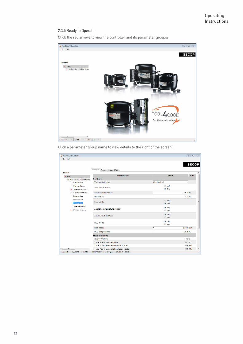
2.3.5 Ready to Operate
Click a parameter group name to view details to the right of the screen:
Click the red arrows to view the controller and its parameter groups:
27
OperatingInstructions3.
TOOL4COOL® SOFTWARE INTERFACE
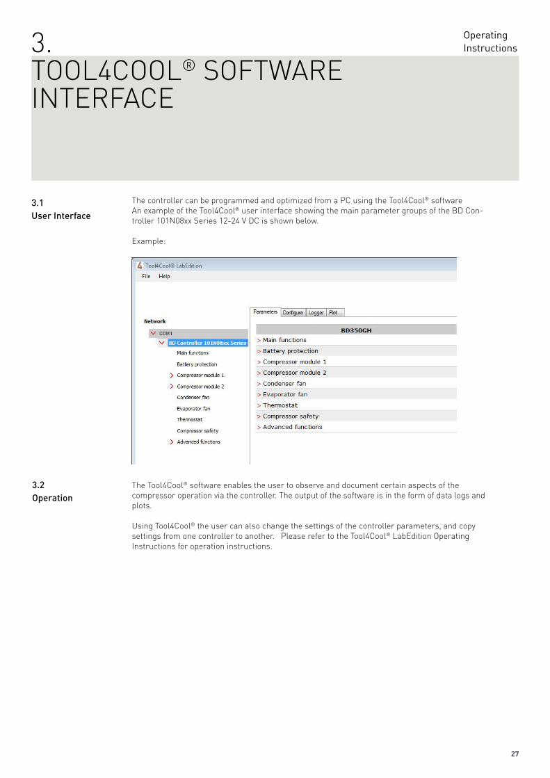
The controller can be programmed and optimized from a PC using the Tool4Cool® software An example of the Tool4Cool® user interface showing the main parameter groups of the BD Con-troller 101N08xx Series 12-24 V DC is shown below.
Example:
The Tool4Cool® software enables the user to observe and document certain aspects of the compressor operation via the controller. The output of the software is in the form of data logs and plots.
Using Tool4Cool® the user can also change the settings of the controller parameters, and copy settings from one controller to another. Please refer to the Tool4Cool® LabEdition Operating Instructions for operation instructions.
3.1UserInterface
3.2Operation
28
OperatingInstructions
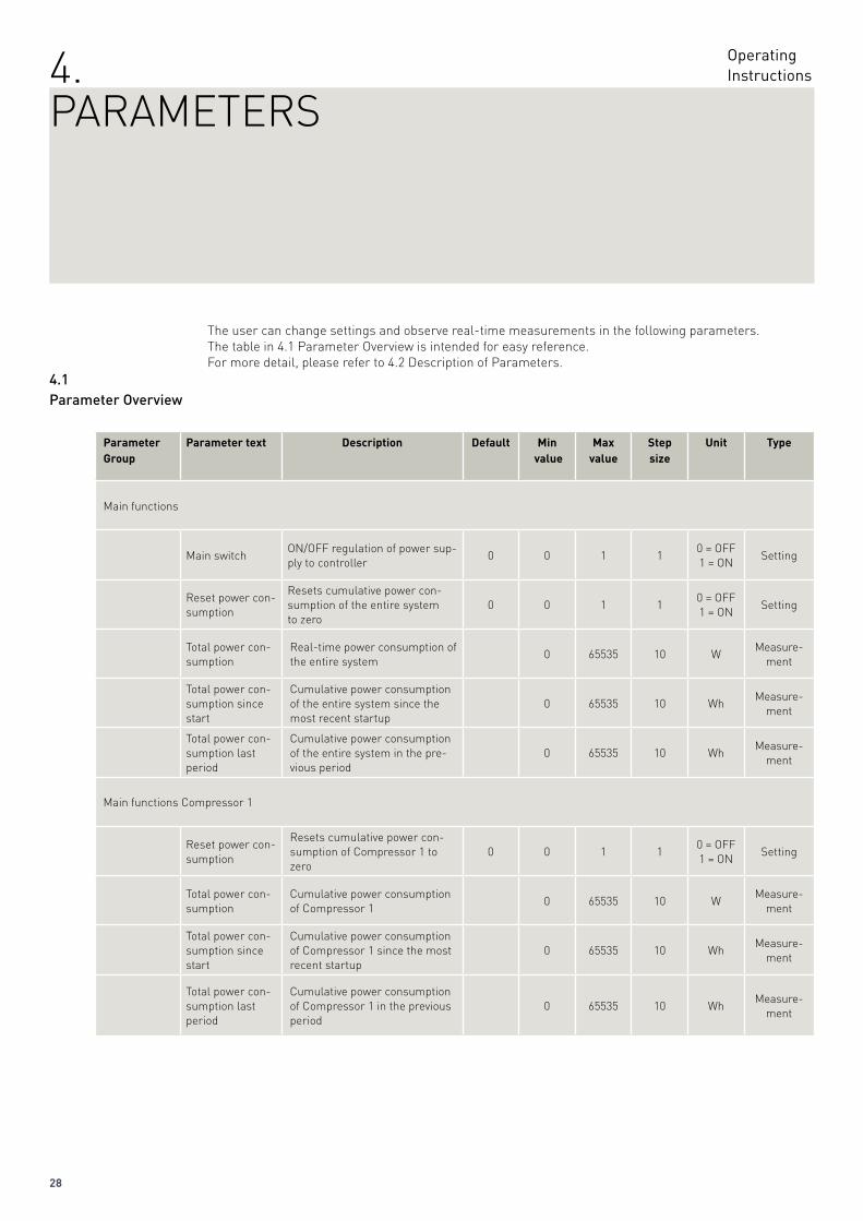
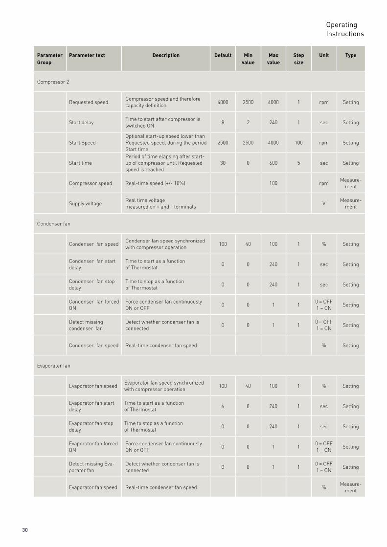
The user can change settings and observe real-time measurements in the following parameters.The table in 4.1 Parameter Overview is intended for easy reference.For more detail, please refer to 4.2 Description of Parameters.
Parameter Group
Parameter text Description Default Min value
Max value
Step size
Unit Type
Main functions
Main switchON/OFF regulation of power sup-ply to controller
0 0 1 10 = OFF1 = ON
Setting
Reset power con-sumption
Resets cumulative power con-sumption of the entire system to zero
0 0 1 10 = OFF1 = ON
Setting
Total power con-sumption
Real-time power consumption of the entire system
0 65535 10 WMeasure-
ment
Total power con-sumption since start
Cumulative power consumption of the entire system since the most recent startup
0 65535 10 WhMeasure-
ment
Total power con-sumption last period
Cumulative power consumption of the entire system in the pre-vious period
0 65535 10 WhMeasure-
ment
Main functions Compressor 1
Reset power con-sumption
Resets cumulative power con-sumption of Compressor 1 to zero
0 0 1 10 = OFF1 = ON
Setting
Total power con-sumption
Cumulative power consumption of Compressor 1
0 65535 10 WMeasure-
ment
Total power con-sumption since start
Cumulative power consumption of Compressor 1 since the most recent startup
0 65535 10 WhMeasure-
ment
Total power con-sumption last period
Cumulative power consumption of Compressor 1 in the previous period
0 65535 10 WhMeasure-
ment
4.1ParameterOverview
4.PARAMETERS
29
OperatingInstructions
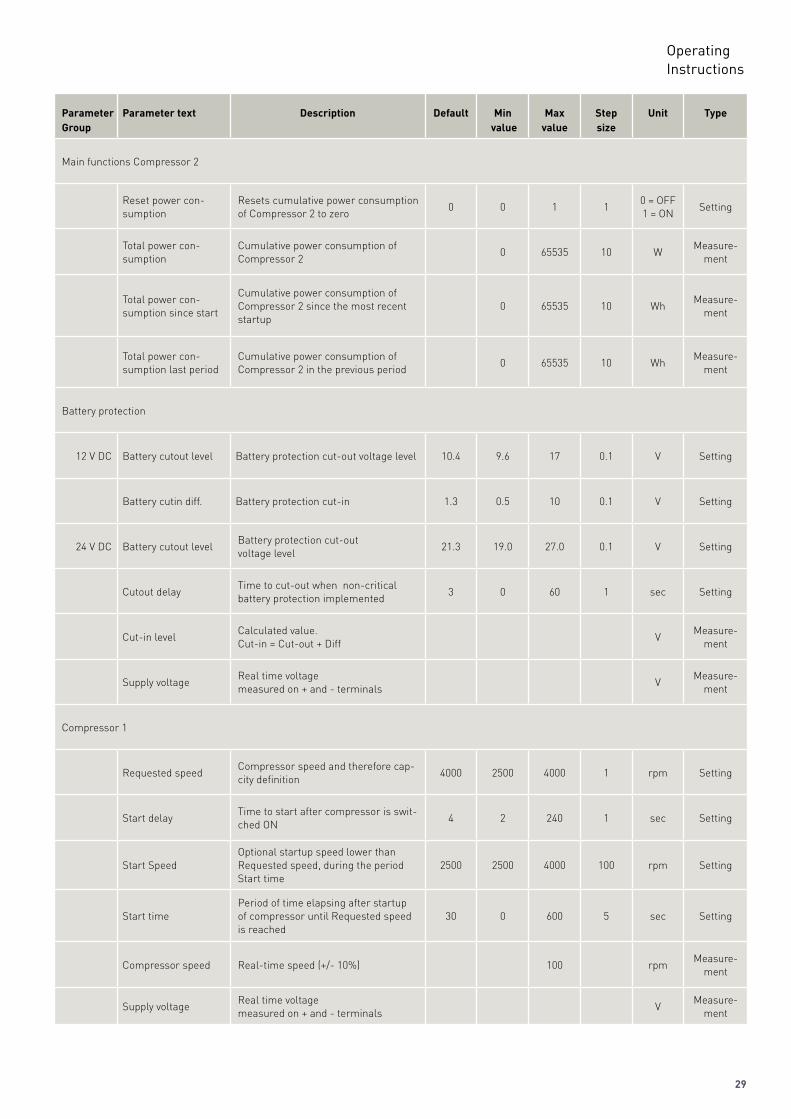
Parameter Group
Parameter text Description Default Min value
Max value
Step size
Unit Type
Main functions Compressor 2
Reset power con-sumption
Resets cumulative power consumption of Compressor 2 to zero
0 0 1 10 = OFF1 = ON
Setting
Total power con-sumption
Cumulative power consumption of Compressor 2
0 65535 10 WMeasure-
ment
Total power con-sumption since start
Cumulative power consumption of Compressor 2 since the most recent startup
0 65535 10 WhMeasure-
ment
Total power con-sumption last period
Cumulative power consumption of Compressor 2 in the previous period
0 65535 10 WhMeasure-
ment
Battery protection
12 V DC Battery cutout level Battery protection cut-out voltage level 10.4 9.6 17 0.1 V Setting
Battery cutin diff. Battery protection cut-in 1.3 0.5 10 0.1 V Setting
24 V DC Battery cutout levelBattery protection cut-outvoltage level
21.3 19.0 27.0 0.1 V Setting
Cutout delayTime to cut-out when non-critical battery protection implemented
3 0 60 1 sec Setting
Cut-in levelCalculated value.Cut-in = Cut-out + Diff
VMeasure-
ment
Supply voltageReal time voltagemeasured on + and - terminals
VMeasure-
ment
Compressor 1
Requested speedCompressor speed and therefore cap-city definition
4000 2500 4000 1 rpm Setting
Start delayTime to start after compressor is swit-ched ON
4 2 240 1 sec Setting
Start SpeedOptional startup speed lower than Requested speed, during the period Start time
2500 2500 4000 100 rpm Setting
Start timePeriod of time elapsing after startup of compressor until Requested speed is reached
30 0 600 5 sec Setting
Compressor speed Real-time speed (+/- 10%) 100 rpmMeasure-
ment
Supply voltageReal time voltagemeasured on + and - terminals
VMeasure-
ment
30
OperatingInstructions
Parameter Group
Parameter text Description Default Min value
Max value
Step size
Unit Type
Compressor 2
Requested speedCompressor speed and therefore capacity definition
4000 2500 4000 1 rpm Setting
Start delayTime to start after compressor is switched ON
8 2 240 1 sec Setting
Start SpeedOptional start-up speed lower than Requested speed, during the period Start time
2500 2500 4000 100 rpm Setting
Start timePeriod of time elapsing after start-up of compressor until Requested speed is reached
30 0 600 5 sec Setting
Compressor speed Real-time speed (+/- 10%) 100 rpmMeasure-
ment
Supply voltageReal time voltagemeasured on + and - terminals
VMeasure-
ment
Condenser fan
Condenser fan speedCondenser fan speed synchronized with compressor operation
100 40 100 1 % Setting
Condenser fan start delay
Time to start as a functionof Thermostat
0 0 240 1 sec Setting
Condenser fan stop delay
Time to stop as a functionof Thermostat
0 0 240 1 sec Setting
Condenser fan forced ON
Force condenser fan continuously ON or OFF
0 0 1 10 = OFF1 = ON
Setting
Detect missingcondenser fan
Detect whether condenser fan is connected
0 0 1 10 = OFF1 = ON
Setting
Condenser fan speed Real-time condenser fan speed % Setting
Evaporater fan
Evaporator fan speedEvaporator fan speed synchronized with compressor operation
100 40 100 1 % Setting
Evaporator fan start delay
Time to start as a functionof Thermostat
6 0 240 1 sec Setting
Evaporator fan stop delay
Time to stop as a functionof Thermostat
0 0 240 1 sec Setting
Evaporator fan forced ON
Force condenser fan continuously ON or OFF
0 0 1 10 = OFF1 = ON
Setting
Detect missing Eva-porator fan
Detect whether condenser fan is connected
0 0 1 10 = OFF1 = ON
Setting
Evaporator fan speed Real-time condenser fan speed %Measure-
ment
31
OperatingInstructions
Parameter Group
Parameter text
Description Default Min value
Max value
Step size
Unit Type
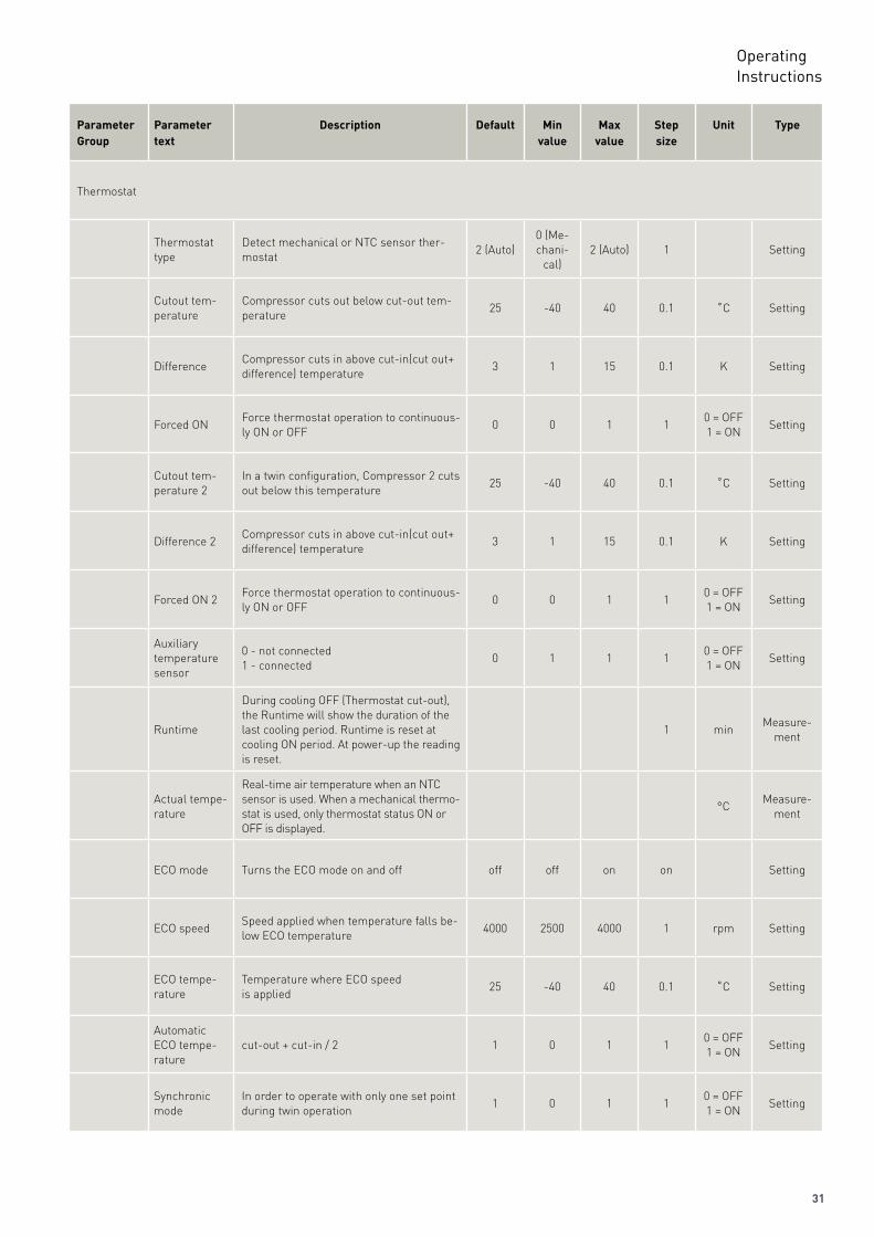
Thermostat
Thermostat type
Detect mechanical or NTC sensor ther-mostat
2 (Auto)0 (Me-chani-
cal)2 (Auto) 1 Setting
Cutout tem-perature
Compressor cuts out below cut-out tem-perature
25 -40 40 0.1 ˚C Setting
DifferenceCompressor cuts in above cut-in(cut out+ difference) temperature
3 1 15 0.1 K Setting
Forced ONForce thermostat operation to continuous-ly ON or OFF
0 0 1 10 = OFF1 = ON
Setting
Cutout tem-perature 2
In a twin configuration, Compressor 2 cuts out below this temperature
25 -40 40 0.1 ˚C Setting
Difference 2Compressor cuts in above cut-in(cut out+ difference) temperature
3 1 15 0.1 K Setting
Forced ON 2Force thermostat operation to continuous-ly ON or OFF
0 0 1 10 = OFF1 = ON
Setting
Auxiliary temperature sensor
0 - not connected1 - connected
0 1 1 10 = OFF1 = ON
Setting
Runtime
During cooling OFF (Thermostat cut-out), the Runtime will show the duration of the last cooling period. Runtime is reset at cooling ON period. At power-up the reading is reset.
1 minMeasure-
ment
Actual tempe-rature
Real-time air temperature when an NTC sensor is used. When a mechanical thermo-stat is used, only thermostat status ON or OFF is displayed.
°CMeasure-
ment
ECO mode Turns the ECO mode on and off off off on on Setting
ECO speedSpeed applied when temperature falls be-low ECO temperature
4000 2500 4000 1 rpm Setting
ECO tempe-rature
Temperature where ECO speedis applied
25 -40 40 0.1 ˚C Setting
Automatic ECO tempe-rature
cut-out + cut-in / 2 1 0 1 10 = OFF1 = ON
Setting
Synchronic mode
In order to operate with only one set point during twin operation
1 0 1 10 = OFF1 = ON
Setting
32
OperatingInstructions
Parameter Group
Parameter Description Default Min value
Maxvalue
Step size
Unit Type
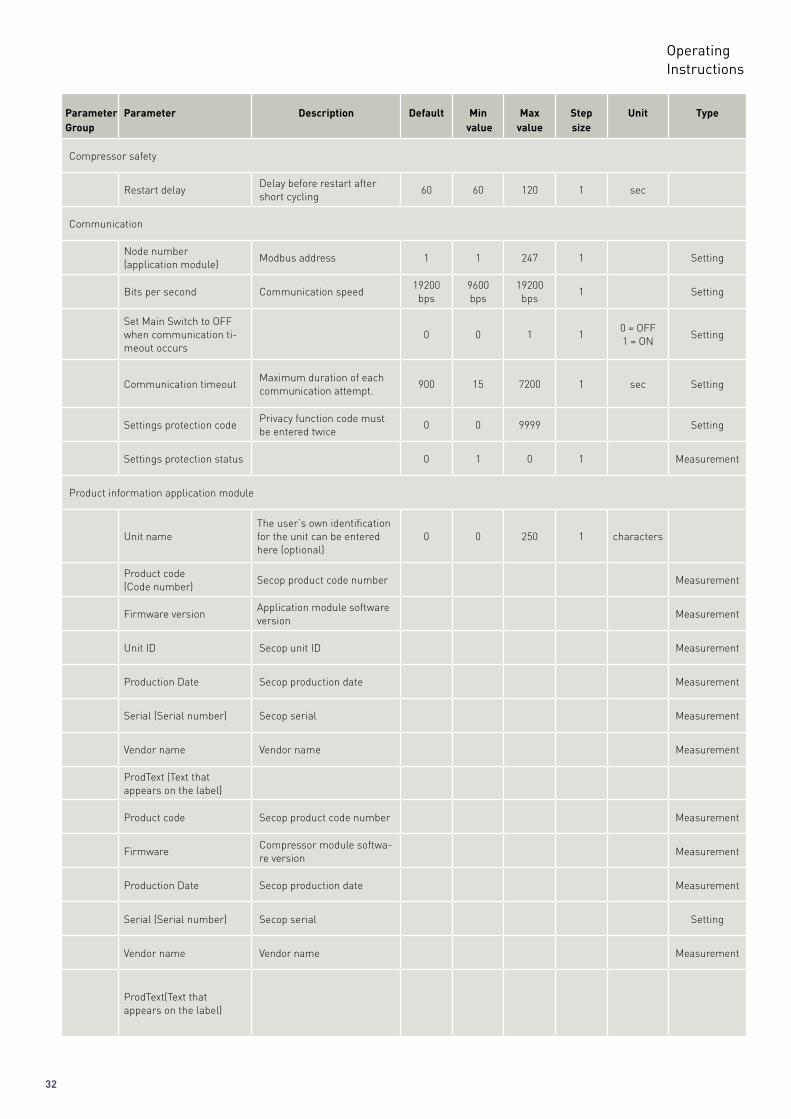
Compressor safety
Restart delayDelay before restart after short cycling
60 60 120 1 sec
Communication
Node number(application module)
Modbus address 1 1 247 1 Setting
Bits per second Communication speed19200 bps
9600 bps
19200 bps
1 Setting
Set Main Switch to OFF when communication ti-meout occurs
0 0 1 10 = OFF1 = ON
Setting
Communication timeoutMaximum duration of each communication attempt.
900 15 7200 1 sec Setting
Settings protection codePrivacy function code must be entered twice
0 0 9999 Setting
Settings protection status 0 1 0 1 Measurement
Product information application module
Unit nameThe user’s own identification for the unit can be entered here (optional)
0 0 250 1 characters
Product code(Code number)
Secop product code number Measurement
Firmware versionApplication module software version
Measurement
Unit ID Secop unit ID Measurement
Production Date Secop production date Measurement
Serial (Serial number) Secop serial Measurement
Vendor name Vendor name Measurement
ProdText (Text thatappears on the label)
Product code Secop product code number Measurement
FirmwareCompressor module softwa-re version
Measurement
Production Date Secop production date Measurement
Serial (Serial number) Secop serial Setting
Vendor name Vendor name Measurement
ProdText(Text thatappears on the label)
33
OperatingInstructions
Parameter Group
Parameter Description Default Minvalue
Maxvalue
Step size
Unit Type
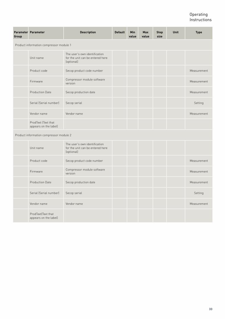
Product information compressor module 1
Unit nameThe user’s own identification for the unit can be entered here (optional)
Product code Secop product code number Measurement
FirmwareCompressor module software version
Measurement
Production Date Secop production date Measurement
Serial (Serial number) Secop serial Setting
Vendor name Vendor name Measurement
ProdText (Text thatappears on the label)
Product information compressor module 2
Unit nameThe user’s own identification for the unit can be entered here (optional)
Product code Secop product code number Measurement
FirmwareCompressor module software version
Measurement
Production Date Secop production date Measurement
Serial (Serial number) Secop serial Setting
Vendor name Vendor name Measurement
ProdText(Text thatappears on the label)
34
OperatingInstructions
Parameter Group
Parameter Description Default Min value
Maxvalue
Step size
Unit Type
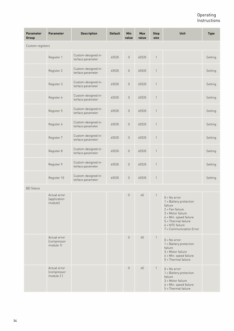
Custom registers
Register 1Custom-designed in-terface parameter
65535 0 65535 1 Setting
Register 2Custom-designed in-terface parameter
65535 0 65535 1 Setting
Register 3Custom-designed in-terface parameter
65535 0 65535 1 Setting
Register 4Custom-designed in-terface parameter
65535 0 65535 1 Setting
Register 5Custom-designed in-terface parameter
65535 0 65535 1 Setting
Register 6Custom-designed in-terface parameter
65535 0 65535 1 Setting
Register 7Custom-designed in-terface parameter
65535 0 65535 1 Setting
Register 8Custom-designed in-terface parameter
65535 0 65535 1 Setting
Register 9Custom-designed in-terface parameter
65535 0 65535 1 Setting
Register 10Custom-designed in-terface parameter
65535 0 65535 1 Setting
BD Status
Actual error(application module)
0 40 10 = No error1 = Battery protection failure2 = Fan failure3 = Motor failure4 = Min. speed failure5 = Thermal failure6 = NTC failure7 = Communication Error
Actual error(compressor module 1)
0 40 10 = No error1 = Battery protection failure3 = Motor failure4 = Min. speed failure5 = Thermal failure
Actual error (compressor module 2 )
0 40 1 0 = No error1 = Battery protection failure3 = Motor failure4 = Min. speed failure5 = Thermal failure
35
OperatingInstructions
Parameter Group
Parameter Description Default Min value
Maxvalue
Step size
Unit Type
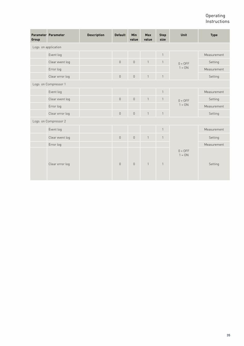
Logs on application
Event log 1
0 = OFF1 = ON
Measurement
Clear event log 0 0 1 1 Setting
Error log Measurement
Clear error log 0 0 1 1 Setting
Logs on Compressor 1
Event log 1
0 = OFF1 = ON
Measurement
Clear event log 0 0 1 1 Setting
Error log Measurement
Clear error log 0 0 1 1 Setting
Logs on Compressor 2
Event log 1
0 = OFF1 = ON
Measurement
Clear event log 0 0 1 1 Setting
Error log Measurement
Clear error log 0 0 1 1 Setting
36
OperatingInstructions
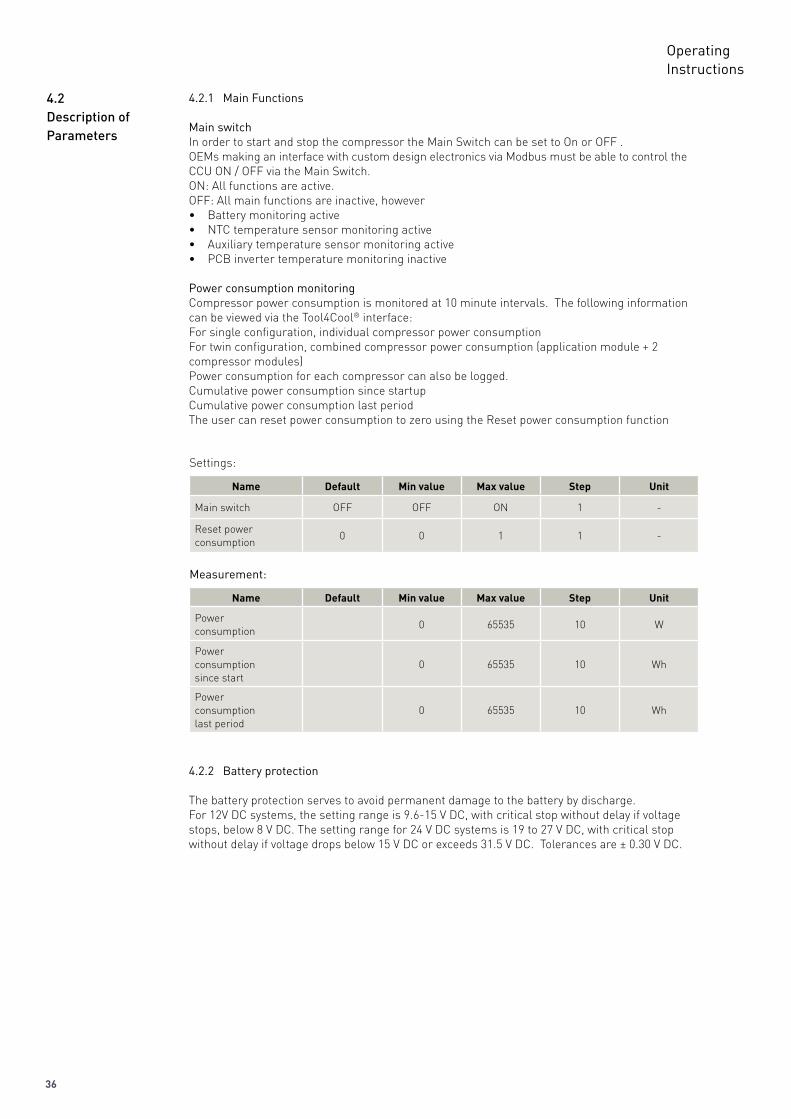
4.2.2 Battery protection
The battery protection serves to avoid permanent damage to the battery by discharge.For 12V DC systems, the setting range is 9.6-15 V DC, with critical stop without delay if voltage stops, below 8 V DC. The setting range for 24 V DC systems is 19 to 27 V DC, with critical stop without delay if voltage drops below 15 V DC or exceeds 31.5 V DC. Tolerances are ± 0.30 V DC.
Settings:
Name Default Min value Max value Step Unit
Main switch OFF OFF ON 1 -
Reset powerconsumption
0 0 1 1 -
4.2.1 Main Functions
Main switchIn order to start and stop the compressor the Main Switch can be set to On or OFF .OEMs making an interface with custom design electronics via Modbus must be able to control the CCU ON / OFF via the Main Switch.ON: All functions are active.OFF: All main functions are inactive, however• Battery monitoring active• NTC temperature sensor monitoring active• Auxiliary temperature sensor monitoring active• PCB inverter temperature monitoring inactive
Power consumption monitoringCompressor power consumption is monitored at 10 minute intervals. The following information can be viewed via the Tool4Cool® interface:For single configuration, individual compressor power consumptionFor twin configuration, combined compressor power consumption (application module + 2compressor modules)Power consumption for each compressor can also be logged.Cumulative power consumption since startupCumulative power consumption last periodThe user can reset power consumption to zero using the Reset power consumption function
Measurement:
Name Default Min value Max value Step Unit
Powerconsumption
0 65535 10 W
Powerconsumptionsince start
0 65535 10 Wh
Powerconsumptionlast period
0 65535 10 Wh
4.2DescriptionofParameters
37
OperatingInstructions
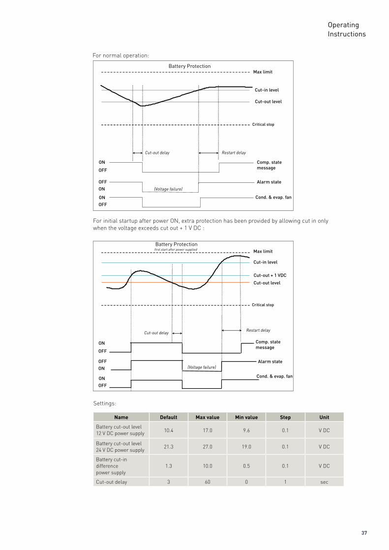
Battery ProtectionMax limit
Cut-in level
Cut-out level
Critical stop
Restart delayCut-out delay
ON
ON
ON
OFF
OFF
OFF
(Voltage failure)
Alarm state
Comp. state message
Cond. & evap. fan
For initial startup after power ON, extra protection has been provided by allowing cut in only when the voltage exceeds cut out + 1 V DC :
Battery Protectionfirst start after power supplied Max limit
Cut-in level
Cut-out level
Cut-out + 1 VDC
Critical stop
Restart delayCut-out delay
Alarm state
Comp. state message
Cond. & evap. fan
(Voltage failure)
ON
ON
ON
OFF
OFF
OFF
Settings:
Name Default Max value Min value Step Unit
Battery cut-out level 12 V DC power supply 10.4 17.0 9.6 0.1 V DC
Battery cut-out level 24 V DC power supply
21.3 27.0 19.0 0.1 V DC
Battery cut-indifferencepower supply
1.3 10.0 0.5 0.1 V DC
Cut-out delay 3 60 0 1 sec
For normal operation:
38
OperatingInstructions
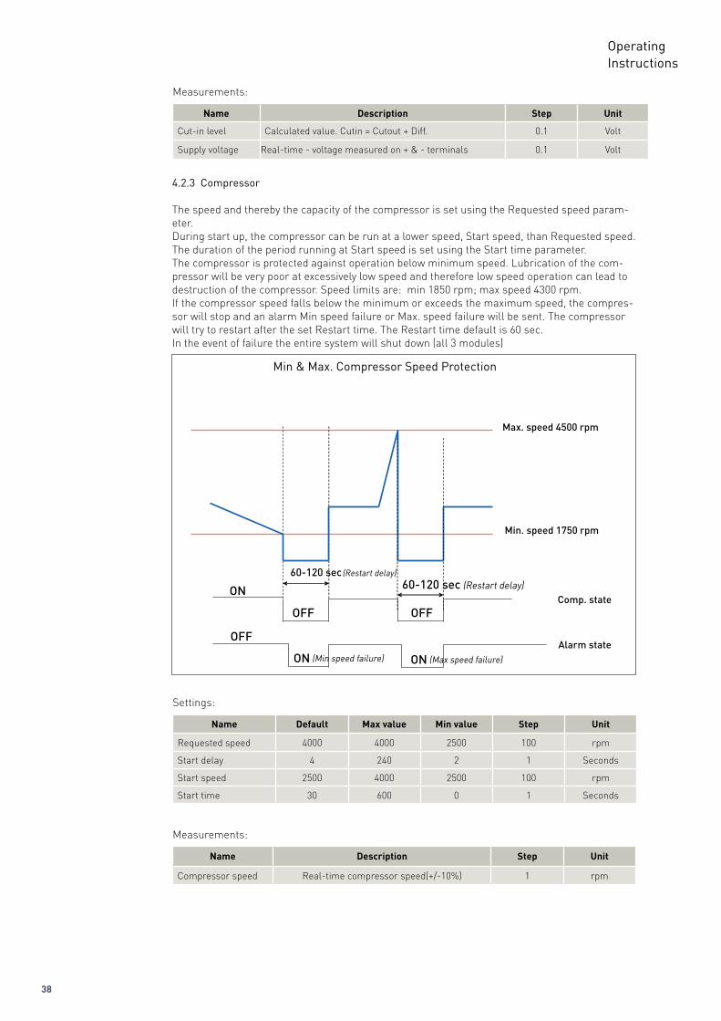
4.2.3 Compressor
The speed and thereby the capacity of the compressor is set using the Requested speed param-eter.During start up, the compressor can be run at a lower speed, Start speed, than Requested speed.The duration of the period running at Start speed is set using the Start time parameter.The compressor is protected against operation below minimum speed. Lubrication of the com-pressor will be very poor at excessively low speed and therefore low speed operation can lead to destruction of the compressor. Speed limits are: min 1850 rpm; max speed 4300 rpm.If the compressor speed falls below the minimum or exceeds the maximum speed, the compres-sor will stop and an alarm Min speed failure or Max. speed failure will be sent. The compressor will try to restart after the set Restart time. The Restart time default is 60 sec.In the event of failure the entire system will shut down (all 3 modules)
Min & Max. Compressor Speed Protection
Max. speed 4500 rpm
Min. speed 1750 rpm
Comp. state
Alarm state
ON
OFF
OFF OFF
ON (Min speed failure) ON (Max speed failure)
60-120 sec (Restart delay)60-120 sec (Restart delay)
Settings:
Name Default Max value Min value Step Unit
Requested speed 4000 4000 2500 100 rpm
Start delay 4 240 2 1 Seconds
Start speed 2500 4000 2500 100 rpm
Start time 30 600 0 1 Seconds
Measurements:
Name Description Step Unit
Compressor speed Real-time compressor speed(+/-10%) 1 rpm
Measurements:
Name Description Step Unit
Cut-in level Calculated value. Cutin = Cutout + Diff. 0.1 Volt
Supply voltage Real-time - voltage measured on + & - terminals 0.1 Volt
39
OperatingInstructions
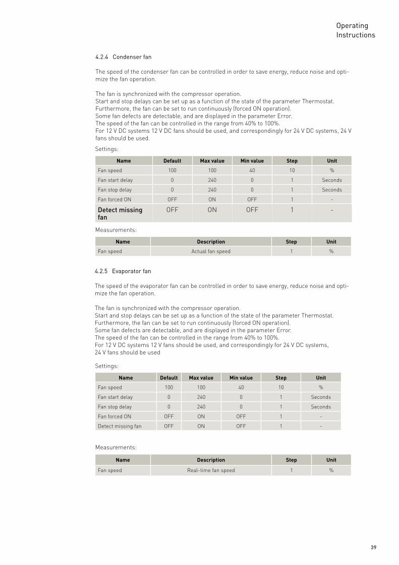
4.2.4 Condenser fan
The speed of the condenser fan can be controlled in order to save energy, reduce noise and opti-mize the fan operation.
The fan is synchronized with the compressor operation.Start and stop delays can be set up as a function of the state of the parameter Thermostat.Furthermore, the fan can be set to run continuously (forced ON operation).Some fan defects are detectable, and are displayed in the parameter Error.The speed of the fan can be controlled in the range from 40% to 100%. For 12 V DC systems 12 V DC fans should be used, and correspondingly for 24 V DC systems, 24 V fans should be used.
Settings:
Name Default Max value Min value Step Unit
Fan speed 100 100 40 10 %
Fan start delay 0 240 0 1 Seconds
Fan stop delay 0 240 0 1 Seconds
Fan forced ON OFF ON OFF 1 -
Detectmissingfan
OFF ON OFF 1 -
Measurements:
Name Description Step Unit
Fan speed Actual fan speed 1 %
4.2.5 Evaporator fan
The speed of the evaporator fan can be controlled in order to save energy, reduce noise and opti-mize the fan operation.
The fan is synchronized with the compressor operation.Start and stop delays can be set up as a function of the state of the parameter Thermostat.Furthermore, the fan can be set to run continuously (forced ON operation).Some fan defects are detectable, and are displayed in the parameter Error.The speed of the fan can be controlled in the range from 40% to 100%.For 12 V DC systems 12 V fans should be used, and correspondingly for 24 V DC systems,24 V fans should be used
Settings:
Name Default Max value Min value Step Unit
Fan speed 100 100 40 10 %
Fan start delay 0 240 0 1 Seconds
Fan stop delay 0 240 0 1 Seconds
Fan forced ON OFF ON OFF 1 -
Detect missing fan OFF ON OFF 1 -
Measurements:
Name Description Step Unit
Fan speed Real-time fan speed 1 %
40
OperatingInstructions
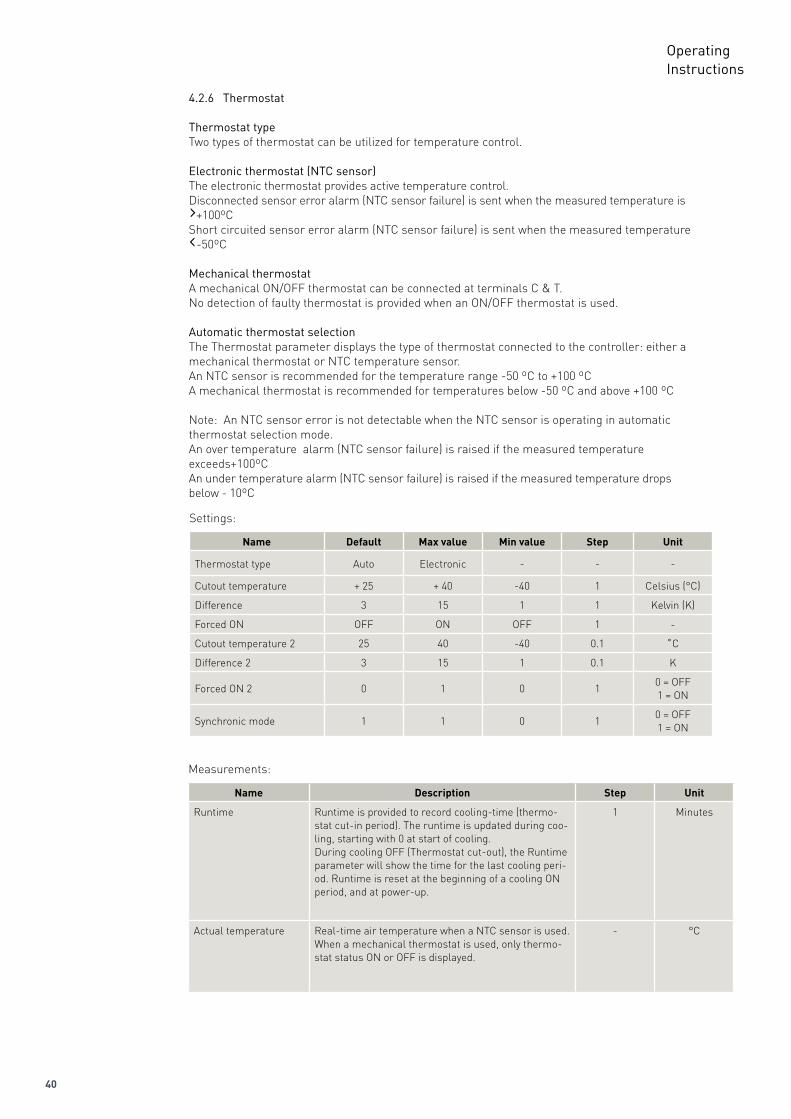
4.2.6 Thermostat
Thermostat typeTwo types of thermostat can be utilized for temperature control.
Electronic thermostat (NTC sensor)The electronic thermostat provides active temperature control.Disconnected sensor error alarm (NTC sensor failure) is sent when the measured temperature is ›+100ºCShort circuited sensor error alarm (NTC sensor failure) is sent when the measured temperature ‹-50ºC
Mechanical thermostatA mechanical ON/OFF thermostat can be connected at terminals C & T. No detection of faulty thermostat is provided when an ON/OFF thermostat is used.
Automatic thermostat selectionThe Thermostat parameter displays the type of thermostat connected to the controller: either amechanical thermostat or NTC temperature sensor. An NTC sensor is recommended for the temperature range -50 ºC to +100 ºCA mechanical thermostat is recommended for temperatures below -50 ºC and above +100 ºC
Note: An NTC sensor error is not detectable when the NTC sensor is operating in automaticthermostat selection mode.An over temperature alarm (NTC sensor failure) is raised if the measured temperature exceeds+100ºCAn under temperature alarm (NTC sensor failure) is raised if the measured temperature drops below - 10ºC
Settings:
Name Default Max value Min value Step Unit
Thermostat type Auto Electronic - - -
Cutout temperature + 25 + 40 -40 1 Celsius (°C)
Difference 3 15 1 1 Kelvin (K)
Forced ON OFF ON OFF 1 -
Cutout temperature 2 25 40 -40 0.1 ˚C
Difference 2 3 15 1 0.1 K
Forced ON 2 0 1 0 10 = OFF1 = ON
Synchronic mode 1 1 0 10 = OFF1 = ON
Measurements:
Name Description Step Unit
Runtime Runtime is provided to record cooling-time (thermo-stat cut-in period). The runtime is updated during coo-ling, starting with 0 at start of cooling.During cooling OFF (Thermostat cut-out), the Runtime parameter will show the time for the last cooling peri-od. Runtime is reset at the beginning of a cooling ON period, and at power-up.
1 Minutes
Actual temperature Real-time air temperature when a NTC sensor is used. When a mechanical thermostat is used, only thermo-stat status ON or OFF is displayed.
- °C
41
OperatingInstructions
ECO modeAuto calculation of ECO temp. & manual selection of
Temp.
Cut-in temp.
Diff / 2Diff / 2
Diff
Cut-out temp.
ECO temp. =Cut-out +(Diff/2)
Comp.speed
4000
3500
3000
2500
0
“Requested speed” “Eco speed”
“Eco speed”
Settings:
Name Default Max value Min value Step Unit
ECO mode OFF ON OFF 1
ECO speed 2500 4000 2500 1 rpm
ECO temperature 25 40 -40 0.1 Celsius (°C)
Automatic ECO temperature
1 1 0 10 = OFF1 = ON
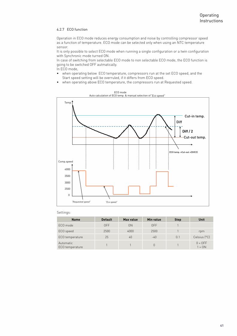
4.2.7 ECO function
Operation in ECO mode reduces energy consumption and noise by controlling compressor speed as a function of temperature. ECO mode can be selected only when using an NTC temperature sensor.It is only possible to select ECO mode when running a single configuration or a twin configuration with Synchronic mode turned ON. In case of switching from selectable ECO mode to non selectable ECO mode, the ECO function is going to be switched OFF autmatically.In ECO mode, • when operating below ECO temperature, compressors run at the set ECO speed, and the Start speed setting will be overruled, if it differs from ECO speed. • when operating above ECO temperature, the compressors run at Requested speed.
42
OperatingInstructions
4.2.9 Communication
Lost communicationThe unit will automatically detect if an external MMI has been connected to the application mod-ule. Once it has been detected it will ensure that the system will not continue to run, when the communication has been lost.
When the communication is lost the entire system will stop and a communication error will be prompted. The communication will stay off until there will be a valid frame on the bus. The error will be erased and the system will start to run again.
Set main to off when communication is lost.When choosing this setting the main will be set to off when the communication is lost. Through that the system will stop. The system will remain off until the MMI has set the main switch to on again.
Protection of settingsA coded privacy function protects customers’ settings from being read by third parties.The code must be verified by entering twice.
Settings:
Name Default Min value Max value Step Unit
Node number 1 1 247 1 -
Bits per second 19200 19200 9600 96000 = Disabled1 = Enabled
Communication 0 0 1 1 Seconds
Communication timeout 900 15 7200 1 -
Setting protection code & status
0 0 9999 1 -
Twin Configuration
Cut in 2
Cut in
Cut out 2
Cut out
Compressor 2 ON
Compressor 2 OFF
Compressor 1 ON
Compressor 1 OFF
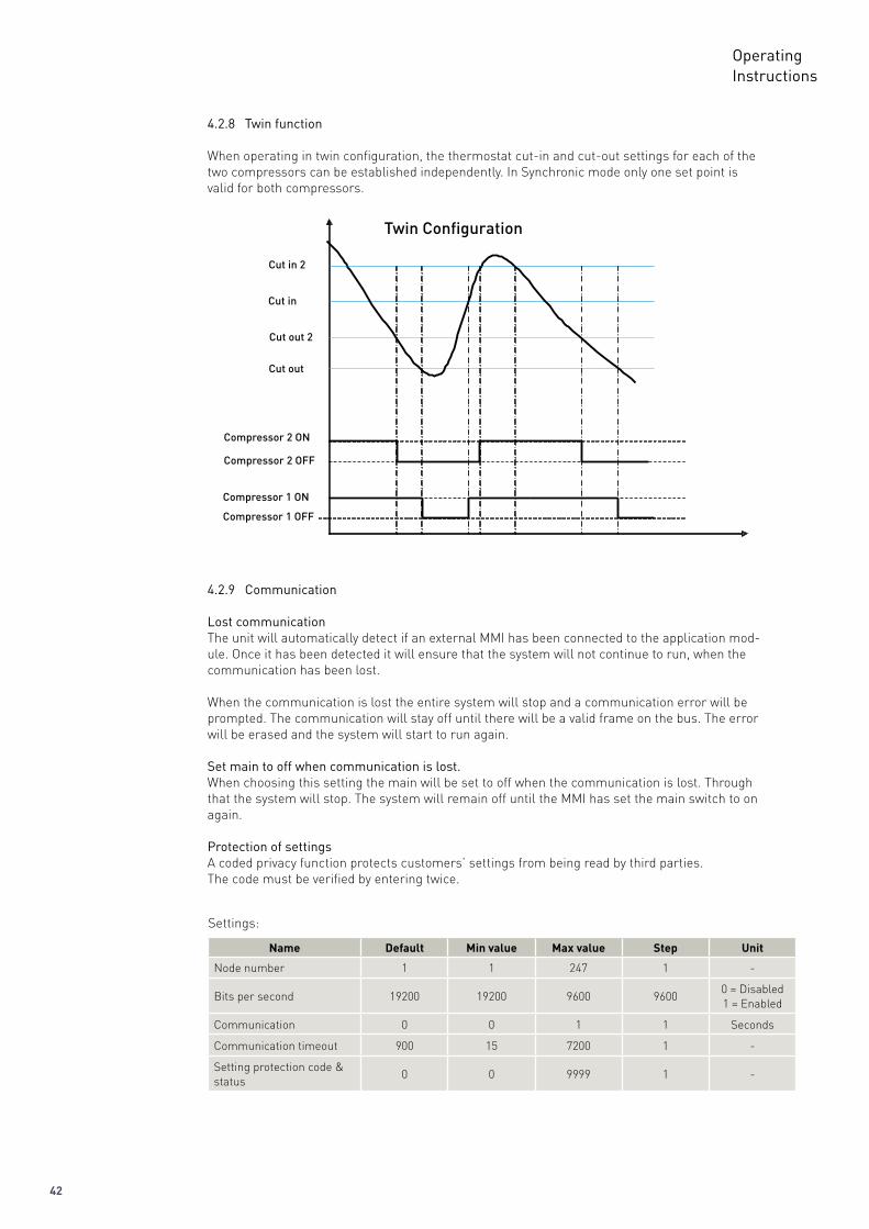
4.2.8 Twin function
When operating in twin configuration, the thermostat cut-in and cut-out settings for each of the two compressors can be established independently. In Synchronic mode only one set point is valid for both compressors.
43
OperatingInstructions
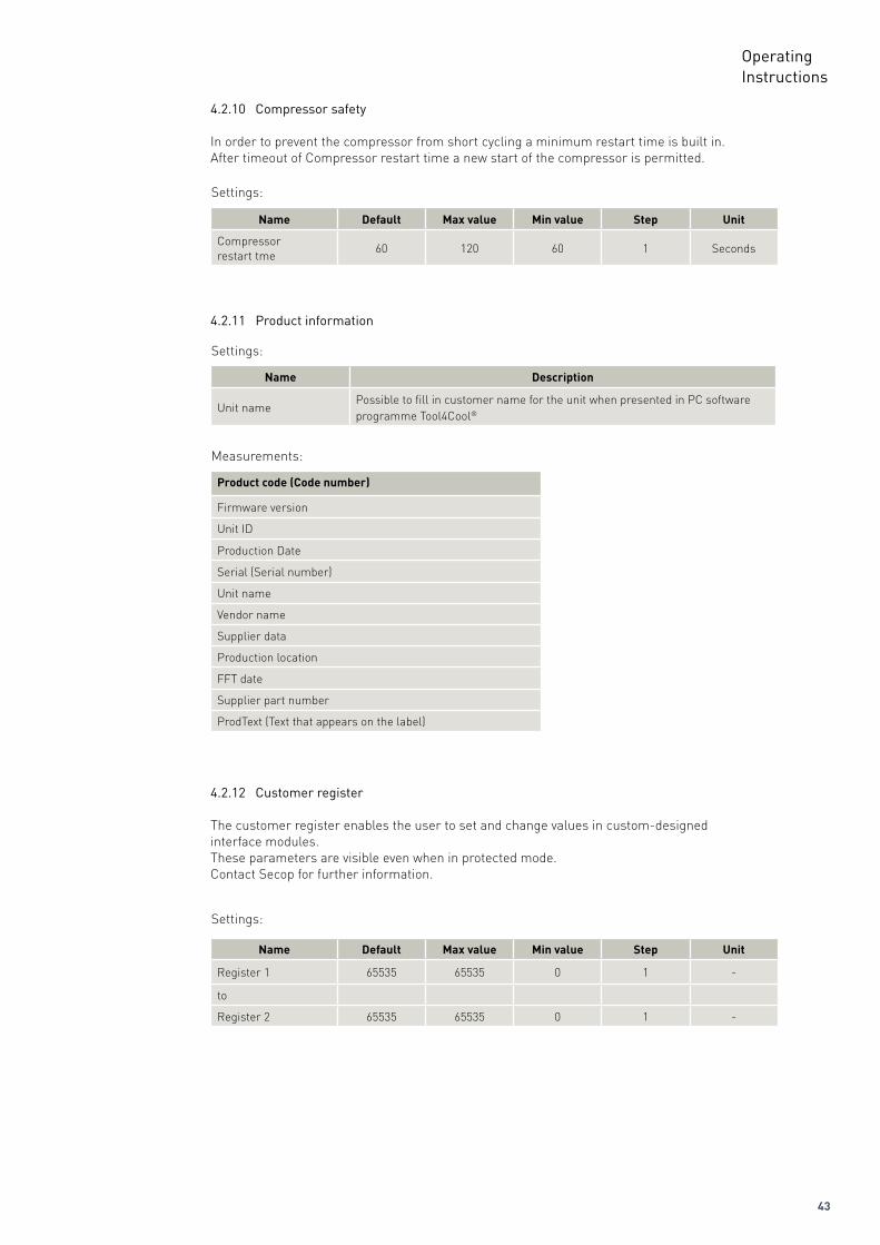
4.2.11 Product information
Settings:
Name Description
Unit namePossible to fill in customer name for the unit when presented in PC software programme Tool4Cool®
4.2.12 Customer register
The customer register enables the user to set and change values in custom-designedinterface modules. These parameters are visible even when in protected mode.Contact Secop for further information.
Measurements:
Product code (Code number)
Firmware version
Unit ID
Production Date
Serial (Serial number)
Unit name
Vendor name
Supplier data
Production location
FFT date
Supplier part number
ProdText (Text that appears on the label)
Settings:
Name Default Max value Min value Step Unit
Register 1 65535 65535 0 1 -
to
Register 2 65535 65535 0 1 -
4.2.10 Compressor safety
In order to prevent the compressor from short cycling a minimum restart time is built in.After timeout of Compressor restart time a new start of the compressor is permitted.
Settings:
Name Default Max value Min value Step Unit
Compressorrestart tme
60 120 60 1 Seconds
44
OperatingInstructions
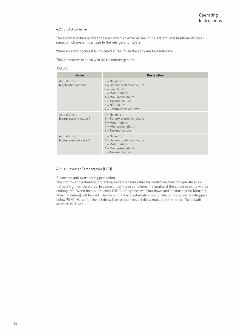
4.2.13 Actual error
The alarm function notifies the user when an error arises in the system, and implements mea-sures which prevent damage to the refrigeration system.
When an error occurs it is indicated at the PC in the software tool interface.
This parameter is on view in all parameter groups.
Output:
Name Description
Actual error(application module)
0 = No errror 1 = Battery protection failure2 = Fan failure3 = Motor failure4 = Min. speed failure5 = Thermal failure6 = NTC failure7 = Communication Error
Actual error(compressor module 1)
0 = No errror1 = Battery protection failure3 = Motor failure4 = Min. speed failure5 = Thermal failure
Actual error(compressor module 2 )
0 = No errror1 = Battery protection failure3 = Motor failure4 = Min. speed failure5 = Thermal failure
4.2.14 Inverter Temperature (PCB)
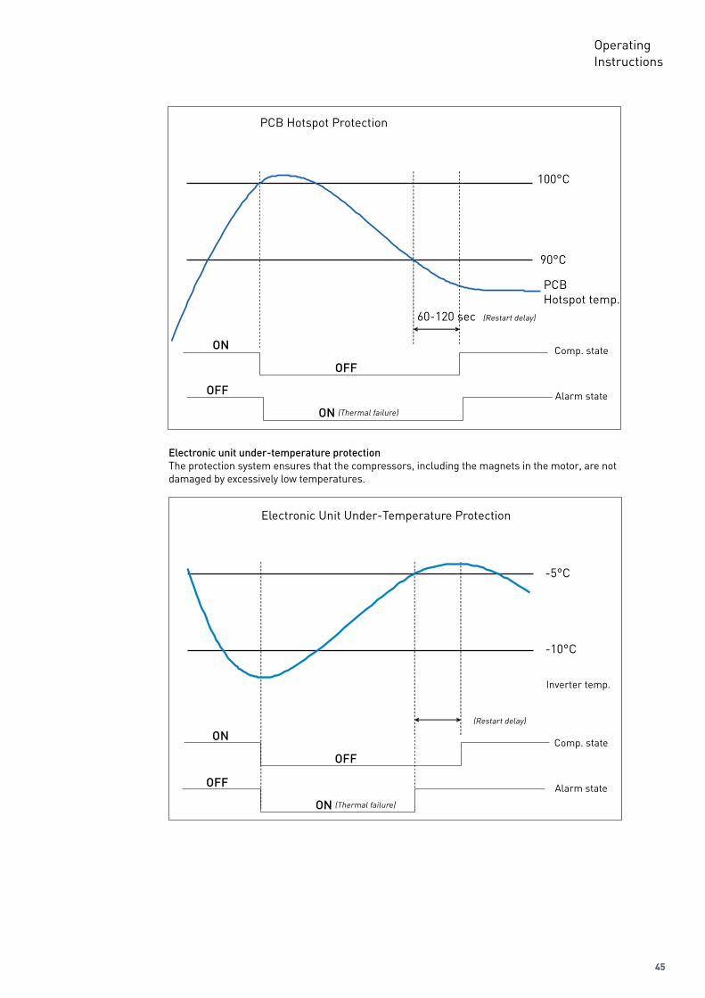
Electronic unit overheating protectionThe controller overheating protection system ensures that the controller does not operate at ex-tremely high temperatures, because under these conditions the quality of the soldered joints will be endangered. When the unit reaches 100 ºC the system will shut down and an alarm error (Alarm 5: Thermal failure) will be sent. The system restarts automatically after the temperature has dropped below 90 ºC. Hereafter the set delay Compressor restart delay must be terminated. The default duration is 60 sec.
45
OperatingInstructions
Electronic Unit Under-Temperature Protection
-5°C
-10°C
Inverter temp.
Alarm state
Comp. state
(Restart delay)
ON
OFF
OFF
ON (Thermal failure)
Electronicunitunder-temperatureprotectionThe protection system ensures that the compressors, including the magnets in the motor, are not damaged by excessively low temperatures.
PCB Hotspot Protection
100°C
90°C
PCB Hotspot temp.
(Restart delay)60-120 sec
Alarm state
Comp. stateON
OFF
OFF
ON (Thermal failure)
46
OperatingInstructions
4.3.1 Error log
The error log records the following data for each error arising:• Time of occurrence related to compressor power up, with 1 sec as sample time• The sequence of occurrence• Number of occurrence (when no value is related to the parameter)• Error name• Sub Error name• The value of the parameter which caused the failure (if connected to a parameter)• Event list reference (changes which caused the failure if a parameter change caused the failure)The error log can be cleared using the clear function.
4.3.2 Event log
The event log records the following parameter and event data to assist in service situations:• Parameter changes (Parameters defined in the parameter)• Power up• Start/Stop signal from application module
The following information is recorded for each event:• Time of occurrence related to compressor power up, with 1 sec as sample time• The sequence of occurrence (Event list reference)• Parameter/Event description• The value of the parameter• Number of occurrence (when no value is related to the parameter)
4.3ErrorandEventLogs
47
OperatingInstructions
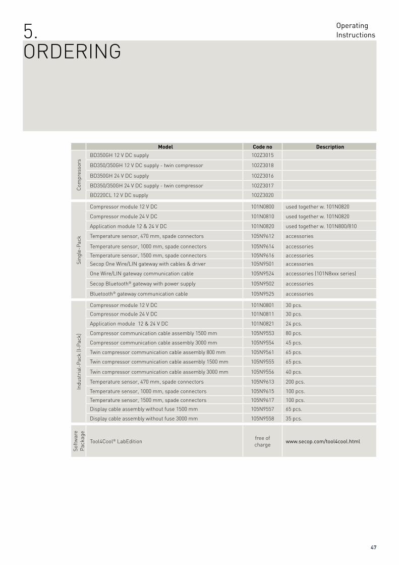
Model Code no Description
Com
pres
sors
BD350GH 12 V DC supply 102Z3015
BD350/350GH 12 V DC supply - twin compressor 102Z3018
BD350GH 24 V DC supply 102Z3016
BD350/350GH 24 V DC supply - twin compressor 102Z3017
BD220CL 12 V DC supply 102Z3020
Sing
le-P
ack
Compressor module 12 V DC 101N0800 used together w. 101N0820
Compressor module 24 V DC 101N0810 used together w. 101N0820
Application module 12 & 24 V DC 101N0820 used together w. 101N800/810
Temperature sensor, 470 mm, spade connectors 105N9612 accessories
Temperature sensor, 1000 mm, spade connectors 105N9614 accessories
Temperature sensor, 1500 mm, spade connectors 105N9616 accessories
Secop One Wire/LIN gateway with cables & driver 105N9501 accessories
One Wire/LIN gateway communication cable 105N9524 accessories (101N8xxx series)
Secop Bluetooth® gateway with power supply 105N9502 accessories
Bluetooth® gateway communication cable 105N9525 accessories
Indu
stri
al-P
ack
(I-P
ack)
Compressor module 12 V DC 101N0801 30 pcs.
Compressor module 24 V DC 101N0811 30 pcs.
Application module 12 & 24 V DC 101N0821 24 pcs.
Compressor communication cable assembly 1500 mm 105N9553 80 pcs.
Compressor communication cable assembly 3000 mm 105N9554 45 pcs.
Twin compressor communication cable assembly 800 mm 105N9561 65 pcs.
Twin compressor communication cable assembly 1500 mm 105N9555 65 pcs.
Twin compressor communication cable assembly 3000 mm 105N9556 40 pcs.
Temperature sensor, 470 mm, spade connectors 105N9613 200 pcs.
Temperature sensor, 1000 mm, spade connectors 105N9615 100 pcs.
Temperature sensor, 1500 mm, spade connectors 105N9617 100 pcs.
Display cable assembly without fuse 1500 mm 105N9557 65 pcs.
Display cable assembly without fuse 3000 mm 105N9558 35 pcs.
Soft
war
e P
acka
ge
Tool4Cool® LabEditionfree ofcharge
www.secop.com/tool4cool.html
5.ORDERING
Produced by Secop | June 2013 DES.S.100.D1.02
Secop can accept no responsibility for possible errors in catalogues, brochures and other printed material. Secop reserves the right to alter its products without notice. This also applies to products already on order provided that such alterations can be made without subsequential changes being necessary in specifications already agreed. All trademarks in this material are property of the respective companies. Secop and the Secop logotype are trademarks of Secop GmbH. All rights reserved
Secop GmbH · Mads-Clausen-Str. 7 · 24939 Flensburg · Germany · Tel: +49 461 4941 0 · www.secop.com
www.secop.com
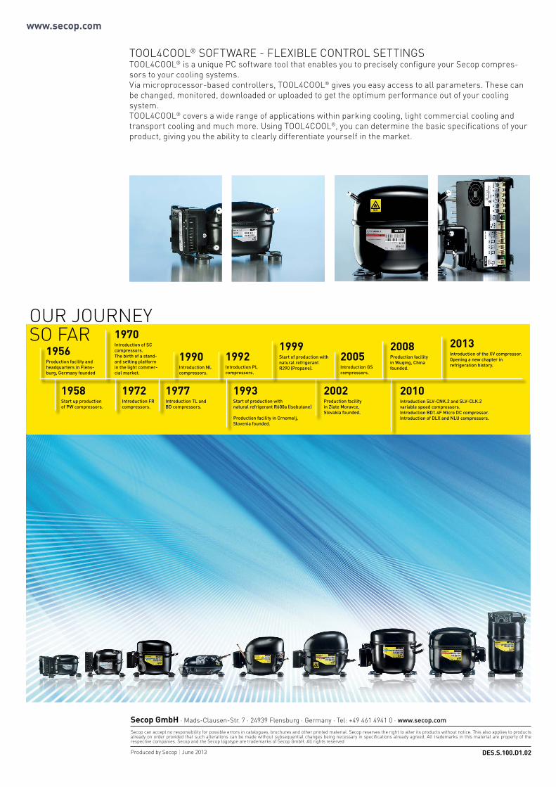
TOOL4COOL® SOFTWARE - FLEXIBLE CONTROL SETTINGSTOOL4COOL® is a unique PC software tool that enables you to precisely configure your Secop compres-sors to your cooling systems. Via microprocessor-based controllers, TOOL4COOL® gives you easy access to all parameters. These can be changed, monitored, downloaded or uploaded to get the optimum performance out of your cooling system.TOOL4COOL® covers a wide range of applications within parking cooling, light commercial cooling and transport cooling and much more. Using TOOL4COOL®, you can determine the basic specifications of your product, giving you the ability to clearly differentiate yourself in the market.
1958StartupproductionofPWcompressors.
1972IntroductionFRcompressors.
1993StartofproductionwithnaturalrefrigerantR600a(Isobutane)
ProductionfacilityinCrnomelj,Sloveniafounded.
2008ProductionfacilityinWuqing,Chinafounded.
1970IntroductionofSCcompressors.Thebirthofastand-ardsettingplatforminthelightcommer-cialmarket.
1990IntroductionNLcompressors.
2002ProductionfacilityinZlateMoravce,Slovakiafounded.
2010IntroductionSLV-CNK.2andSLV-CLK.2variablespeedcompressors.IntroductionBD1.4FMicroDCcompressor.IntroductionofDLXandNLUcompressors.
1956ProductionfacilityandheadquartersinFlens-burg,Germanyfounded
1999StartofproductionwithnaturalrefrigerantR290(Propane).
1977IntroductionTLandBDcompressors.
1992IntroductionPLcompressors.
2005IntroductionGScompressors.
2013IntroductionoftheXVcompressor.Openinganewchapterinrefrigerationhistory.
OUR JOURNEY SO FAR


![l>lf·· E ·B; -I,:,C-·-1·1V · cat. no.i bd lj.657 bd lj.6]5 bd 4630 bd 4·627 bd 4628 bd 4886 bd 4546 bd 4·545 bd 4544 bd 4542 bd lj,588 bd lj.593 bd 0102 bd 4636 bd 4632 bd](https://img.pdfslide.net/doc/110x75/5f7c69bb7d840d18665ab1e6/llf-e-b-ic-11v-cat-noi-bd-lj657-bd-lj65-bd-4630-bd-4627-bd-4628-bd.jpg)