Embed Size (px)
Citation preview

MOTION CONTROL ENGINEERING, INC.11380 WHITE ROCK ROAD
RANCHO CORDOVA, CA 95742TELEPHONE (916) 463-9200 FAX (916) 463-9201
CONTROLLER INSTALLATION MANUAL
VVMC-1000-SCR SERIES MTRACTION CONTROLLER
WITH MAGNETEK DSD412 SCR DRIVE
Compliant with ASME A17.1 -2000 / CSA B44-00 and later codes
PART # 42-02-4022 REV. A .1 September 2008
This manual is for VVMC-1000 Series MControllers with Release 4 software
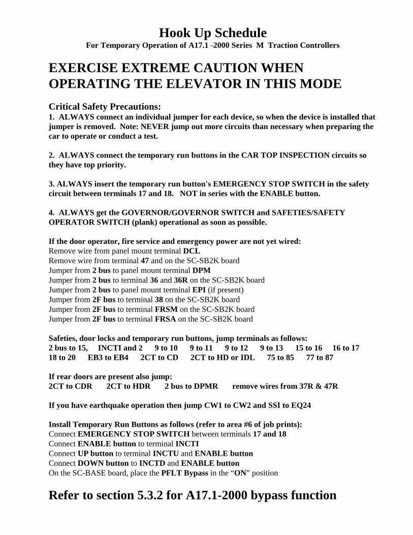
Hook Up ScheduleFor Temporary Operation of A17.1 -2000 Series M Traction Controllers
EXERCISE EXTREME CAUTION WHENOPERATING THE ELEVATOR IN THIS MODE
Critical Safety Precautions: 1. ALWAYS connect an individual jumper for each device, so when the device is installed thatjumper is removed. Note: NEVER jump out more circuits than necessary when preparing thecar to operate or conduct a test.
2. ALWAYS connect the temporary run buttons in the CAR TOP INSPECTION circuits sothey have top priority.
3. ALWAYS insert the temporary run button's EMERGENCY STOP SWITCH in the safetycircuit between terminals 17 and 18. NOT in series with the ENABLE button.
4. ALWAYS get the GOVERNOR/GOVERNOR SWITCH and SAFETIES/SAFETYOPERATOR SWITCH (plank) operational as soon as possible.
If the door operator, fire service and emergency power are not yet wired:Remove wire from panel mount terminal DCLRemove wire from terminal 47 and on the SC-SB2K boardJumper from 2 bus to panel mount terminal DPMJumper from 2 bus to terminal 36 and 36R on the SC-SB2K boardJumper from 2 bus to panel mount terminal EPI (if present)Jumper from 2F bus to terminal 38 on the SC-SB2K boardJumper from 2F bus to terminal FRSM on the SC-SB2K boardJumper from 2F bus to terminal FRSA on the SC-SB2K board Safeties, door locks and temporary run buttons, jump terminals as follows:2 bus to 15, INCTI and 2 9 to 10 9 to 11 9 to 12 9 to 13 15 to 16 16 to 1718 to 20 EB3 to EB4 2CT to CD 2CT to HD or IDL 75 to 85 77 to 87
If rear doors are present also jump:2CT to CDR 2CT to HDR 2 bus to DPMR remove wires from 37R & 47R
If you have earthquake operation then jump CW1 to CW2 and SSI to EQ24 Install Temporary Run Buttons as follows (refer to area #6 of job prints):Connect EMERGENCY STOP SWITCH between terminals 17 and 18Connect ENABLE button to terminal INCTIConnect UP button to terminal INCTU and ENABLE buttonConnect DOWN button to INCTD and ENABLE buttonOn the SC-BASE board, place the PFLT Bypass in the “ON” position
Refer to section 5.3.2 for A17.1-2000 bypass function
42-02-4022 TABLE OF CONTENTS • i
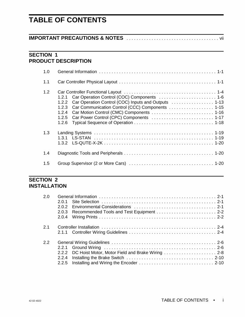
TABLE OF CONTENTS
IMPORTANT PRECAUTIONS & NOTES . . . . . . . . . . . . . . . . . . . . . . . . . . . . . . . . . . . . . vii
SECTION 1PRODUCT DESCRIPTION
1.0 General Information . . . . . . . . . . . . . . . . . . . . . . . . . . . . . . . . . . . . . . . . . . . . . . . 1-1
1.1 Car Controller Physical Layout . . . . . . . . . . . . . . . . . . . . . . . . . . . . . . . . . . . . . . . 1-1
1.2 Car Controller Functional Layout . . . . . . . . . . . . . . . . . . . . . . . . . . . . . . . . . . . . . 1-41.2.1 Car Operation Control (COC) Components . . . . . . . . . . . . . . . . . . . . . . . 1-61.2.2 Car Operation Control (COC) Inputs and Outputs . . . . . . . . . . . . . . . . . 1-131.2.3 Car Communication Control (CCC) Components . . . . . . . . . . . . . . . . . . 1-151.2.4 Car Motion Control (CMC) Components . . . . . . . . . . . . . . . . . . . . . . . . . 1-161.2.5 Car Power Control (CPC) Components . . . . . . . . . . . . . . . . . . . . . . . . . 1-171.2.6 Typical Sequence of Operation . . . . . . . . . . . . . . . . . . . . . . . . . . . . . . . . 1-18
1.3 Landing Systems . . . . . . . . . . . . . . . . . . . . . . . . . . . . . . . . . . . . . . . . . . . . . . . . 1-191.3.1 LS-STAN . . . . . . . . . . . . . . . . . . . . . . . . . . . . . . . . . . . . . . . . . . . . . . . . 1-191.3.2 LS-QUTE-X-2K . . . . . . . . . . . . . . . . . . . . . . . . . . . . . . . . . . . . . . . . . . . . 1-20
1.4 Diagnostic Tools and Peripherals . . . . . . . . . . . . . . . . . . . . . . . . . . . . . . . . . . . . 1-20
1.5 Group Supervisor (2 or More Cars) . . . . . . . . . . . . . . . . . . . . . . . . . . . . . . . . . . 1-20
SECTION 2INSTALLATION
2.0 General Information . . . . . . . . . . . . . . . . . . . . . . . . . . . . . . . . . . . . . . . . . . . . . . . 2-12.0.1 Site Selection . . . . . . . . . . . . . . . . . . . . . . . . . . . . . . . . . . . . . . . . . . . . . . 2-12.0.2 Environmental Considerations . . . . . . . . . . . . . . . . . . . . . . . . . . . . . . . . . 2-12.0.3 Recommended Tools and Test Equipment . . . . . . . . . . . . . . . . . . . . . . . . 2-22.0.4 Wiring Prints . . . . . . . . . . . . . . . . . . . . . . . . . . . . . . . . . . . . . . . . . . . . . . . 2-2
2.1 Controller Installation . . . . . . . . . . . . . . . . . . . . . . . . . . . . . . . . . . . . . . . . . . . . . . 2-42.1.1 Controller Wiring Guidelines . . . . . . . . . . . . . . . . . . . . . . . . . . . . . . . . . . . 2-4
2.2 General Wiring Guidelines . . . . . . . . . . . . . . . . . . . . . . . . . . . . . . . . . . . . . . . . . . 2-62.2.1 Ground Wiring . . . . . . . . . . . . . . . . . . . . . . . . . . . . . . . . . . . . . . . . . . . . . 2-62.2.2 DC Hoist Motor, Motor Field and Brake Wiring . . . . . . . . . . . . . . . . . . . . . 2-82.2.4 Installing the Brake Switch . . . . . . . . . . . . . . . . . . . . . . . . . . . . . . . . . . . 2-102.2.5 Installing and Wiring the Encoder . . . . . . . . . . . . . . . . . . . . . . . . . . . . . . 2-10
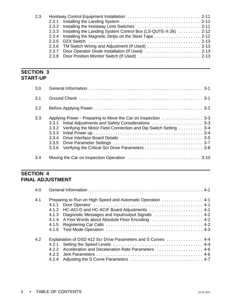
• TABLE OF CONTENTS 42-02-4022ii
2.3 Hoistway Control Equipment Installation . . . . . . . . . . . . . . . . . . . . . . . . . . . . . . 2-112.3.1 Installing the Landing System . . . . . . . . . . . . . . . . . . . . . . . . . . . . . . . . . 2-112.3.2 Installing the Hoistway Limit Switches . . . . . . . . . . . . . . . . . . . . . . . . . . 2-112.3.3 Installing the Landing System Control Box (LS-QUTE-X-2k) . . . . . . . . . 2-122.3.4 Installing the Magnetic Strips on the Steel Tape . . . . . . . . . . . . . . . . . . . 2-122.3.5 DZX Switch . . . . . . . . . . . . . . . . . . . . . . . . . . . . . . . . . . . . . . . . . . . . . . 2-132.3.6 TM Switch Wiring and Adjustment (If Used) . . . . . . . . . . . . . . . . . . . . . . 2-132.3.7 Door Operator Diode Installation (If Used) . . . . . . . . . . . . . . . . . . . . . . . 2-132.3.8 Door Position Monitor Switch (If Used) . . . . . . . . . . . . . . . . . . . . . . . . . 2-13
SECTION 3 START-UP
3.0 General Information . . . . . . . . . . . . . . . . . . . . . . . . . . . . . . . . . . . . . . . . . . . . . . . 3-1
3.1 Ground Check . . . . . . . . . . . . . . . . . . . . . . . . . . . . . . . . . . . . . . . . . . . . . . . . . . . 3-1
3.2 Before Applying Power . . . . . . . . . . . . . . . . . . . . . . . . . . . . . . . . . . . . . . . . . . . . . 3-2
3.3 Applying Power - Preparing to Move the Car on Inspection . . . . . . . . . . . . . . . . . 3-33.3.1 Initial Adjustments and Safety Considerations . . . . . . . . . . . . . . . . . . . . . 3-33.3.2 Verifying the Motor Field Connection and Dip Switch Setting . . . . . . . . . . 3-43.3.3 Initial Power up . . . . . . . . . . . . . . . . . . . . . . . . . . . . . . . . . . . . . . . . . . . . . 3-43.3.4 Drive Interface Board Details . . . . . . . . . . . . . . . . . . . . . . . . . . . . . . . . . . 3-53.3.5 Drive Parameter Settings . . . . . . . . . . . . . . . . . . . . . . . . . . . . . . . . . . . . . 3-73.3.6 Verifying the Critical Scr Drive Parameters . . . . . . . . . . . . . . . . . . . . . . . . 3-8
3.4 Moving the Car on Inspection Operation . . . . . . . . . . . . . . . . . . . . . . . . . . . . . . 3-10
SECTION 4FINAL ADJUSTMENT
4.0 General Information . . . . . . . . . . . . . . . . . . . . . . . . . . . . . . . . . . . . . . . . . . . . . . . 4-1
4.1 Preparing to Run on High Speed and Automatic Operation . . . . . . . . . . . . . . . . . 4-14.1.1 Door Operator . . . . . . . . . . . . . . . . . . . . . . . . . . . . . . . . . . . . . . . . . . . . . 4-14.1.2 HC-ACI-D and HC-ACIF Board Adjustments . . . . . . . . . . . . . . . . . . . . . . 4-14.1.3 Diagnostic Messages and Input/output Signals . . . . . . . . . . . . . . . . . . . . 4-24.1.4 A Few Words about Absolute Floor Encoding . . . . . . . . . . . . . . . . . . . . . 4-24.1.5 Registering Car Calls . . . . . . . . . . . . . . . . . . . . . . . . . . . . . . . . . . . . . . . . 4-24.1.6 Test Mode Operation . . . . . . . . . . . . . . . . . . . . . . . . . . . . . . . . . . . . . . . . 4-3
4.2 Explanation of DSD 412 Scr Drive Parameters and S Curves . . . . . . . . . . . . . . . 4-44.2.1 Setting the Speed Levels . . . . . . . . . . . . . . . . . . . . . . . . . . . . . . . . . . . . . 4-44.2.2 Acceleration and Deceleration Rate Parameters . . . . . . . . . . . . . . . . . . . 4-64.2.3 Jerk Parameters . . . . . . . . . . . . . . . . . . . . . . . . . . . . . . . . . . . . . . . . . . . . 4-64.2.4 Adjusting the S Curve Parameters . . . . . . . . . . . . . . . . . . . . . . . . . . . . . . 4-7
42-02-4022 TABLE OF CONTENTS • iii
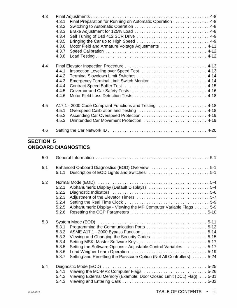
4.3 Final Adjustments . . . . . . . . . . . . . . . . . . . . . . . . . . . . . . . . . . . . . . . . . . . . . . . . . 4-84.3.1 Final Preparation for Running on Automatic Operation . . . . . . . . . . . . . . . 4-84.3.2 Switching to Automatic Operation . . . . . . . . . . . . . . . . . . . . . . . . . . . . . . . 4-84.3.3 Brake Adjustment for 125% Load . . . . . . . . . . . . . . . . . . . . . . . . . . . . . . . 4-84.3.4 Self Tuning of Dsd 412 SCR Drive . . . . . . . . . . . . . . . . . . . . . . . . . . . . . . 4-94.3.5 Bringing the Car up to High Speed . . . . . . . . . . . . . . . . . . . . . . . . . . . . . . 4-94.3.6 Motor Field and Armature Voltage Adjustments . . . . . . . . . . . . . . . . . . . 4-114.3.7 Speed Calibration . . . . . . . . . . . . . . . . . . . . . . . . . . . . . . . . . . . . . . . . . . 4-124.3.8 Load Testing . . . . . . . . . . . . . . . . . . . . . . . . . . . . . . . . . . . . . . . . . . . . . . 4-12
4.4 Final Elevator Inspection Procedure . . . . . . . . . . . . . . . . . . . . . . . . . . . . . . . . . . 4-134.4.1 Inspection Leveling over Speed Test . . . . . . . . . . . . . . . . . . . . . . . . . . . 4-134.4.2 Terminal Slowdown Limit Switches . . . . . . . . . . . . . . . . . . . . . . . . . . . . . 4-144.4.3 Emergency Terminal Limit Switch Monitor . . . . . . . . . . . . . . . . . . . . . . . 4-144.4.4 Contract Speed Buffer Test . . . . . . . . . . . . . . . . . . . . . . . . . . . . . . . . . . 4-154.4.5 Governor and Car Safety Tests . . . . . . . . . . . . . . . . . . . . . . . . . . . . . . . 4-164.4.6 Motor Field Loss Detection Tests . . . . . . . . . . . . . . . . . . . . . . . . . . . . . . 4-18
4.5 A17.1 - 2000 Code Compliant Functions and Testing . . . . . . . . . . . . . . . . . . . . 4-184.5.1 Overspeed Calibration and Testing . . . . . . . . . . . . . . . . . . . . . . . . . . . . 4-184.5.2 Ascending Car Overspeed Protection . . . . . . . . . . . . . . . . . . . . . . . . . . . 4-194.5.3 Unintended Car Movement Protection . . . . . . . . . . . . . . . . . . . . . . . . . . 4-19
4.6 Setting the Car Network ID . . . . . . . . . . . . . . . . . . . . . . . . . . . . . . . . . . . . . . . . . 4-20
SECTION 5 ONBOARD DIAGNOSTICS
5.0 General Information . . . . . . . . . . . . . . . . . . . . . . . . . . . . . . . . . . . . . . . . . . . . . . . 5-1
5.1 Enhanced Onboard Diagnostics (EOD) Overview . . . . . . . . . . . . . . . . . . . . . . . . 5-15.1.1 Description of EOD Lights and Switches . . . . . . . . . . . . . . . . . . . . . . . . . 5-1
5.2 Normal Mode (EOD) . . . . . . . . . . . . . . . . . . . . . . . . . . . . . . . . . . . . . . . . . . . . . . 5-45.2.1 Alphanumeric Display (Default Displays) . . . . . . . . . . . . . . . . . . . . . . . . . 5-45.2.2 Diagnostic Indicators . . . . . . . . . . . . . . . . . . . . . . . . . . . . . . . . . . . . . . . . 5-65.2.3 Adjustment of the Elevator Timers . . . . . . . . . . . . . . . . . . . . . . . . . . . . . . 5-75.2.4 Setting the Real Time Clock . . . . . . . . . . . . . . . . . . . . . . . . . . . . . . . . . . . 5-95.2.5 Alphanumeric Display - Viewing the MP Computer Variable Flags . . . . . . 5-95.2.6 Resetting the CGP Parameters . . . . . . . . . . . . . . . . . . . . . . . . . . . . . . . 5-10
5.3 System Mode (EOD) . . . . . . . . . . . . . . . . . . . . . . . . . . . . . . . . . . . . . . . . . . . . . 5-115.3.1 Programming the Communication Ports . . . . . . . . . . . . . . . . . . . . . . . . . 5-125.3.2 ASME A17.1 - 2000 Bypass Function . . . . . . . . . . . . . . . . . . . . . . . . . . . 5-145.3.3 Viewing and Changing the Security Codes . . . . . . . . . . . . . . . . . . . . . . . 5-155.3.4 Setting MSK: Master Software Key . . . . . . . . . . . . . . . . . . . . . . . . . . . . . 5-175.3.5 Setting the Software Options - Adjustable Control Variables . . . . . . . . . 5-175.3.6 Load Weigher Learn Operation . . . . . . . . . . . . . . . . . . . . . . . . . . . . . . . 5-195.3.7 Setting and Resetting the Passcode Option (Not All Controllers) . . . . . . 5-24
5.4 Diagnostic Mode (EOD) . . . . . . . . . . . . . . . . . . . . . . . . . . . . . . . . . . . . . . . . . . . 5-255.4.1 Viewing the MC-MP2 Computer Flags . . . . . . . . . . . . . . . . . . . . . . . . . . 5-265.4.2 Viewing External Memory (Example: Door Closed Limit (DCL) Flag) . . . 5-315.4.3 Viewing and Entering Calls . . . . . . . . . . . . . . . . . . . . . . . . . . . . . . . . . . . 5-32
• TABLE OF CONTENTS 42-02-4022iv
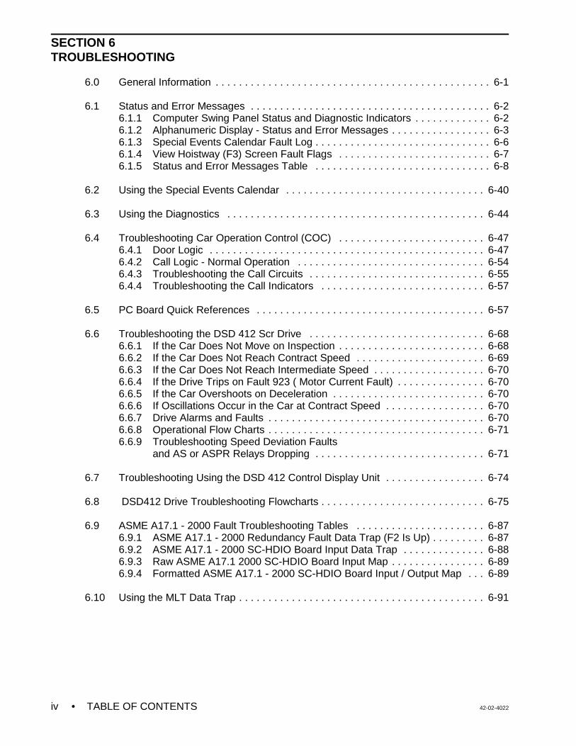
SECTION 6TROUBLESHOOTING
6.0 General Information . . . . . . . . . . . . . . . . . . . . . . . . . . . . . . . . . . . . . . . . . . . . . . . 6-1
6.1 Status and Error Messages . . . . . . . . . . . . . . . . . . . . . . . . . . . . . . . . . . . . . . . . . 6-26.1.1 Computer Swing Panel Status and Diagnostic Indicators . . . . . . . . . . . . . 6-26.1.2 Alphanumeric Display - Status and Error Messages . . . . . . . . . . . . . . . . . 6-36.1.3 Special Events Calendar Fault Log . . . . . . . . . . . . . . . . . . . . . . . . . . . . . . 6-66.1.4 View Hoistway (F3) Screen Fault Flags . . . . . . . . . . . . . . . . . . . . . . . . . . 6-76.1.5 Status and Error Messages Table . . . . . . . . . . . . . . . . . . . . . . . . . . . . . . 6-8
6.2 Using the Special Events Calendar . . . . . . . . . . . . . . . . . . . . . . . . . . . . . . . . . . 6-40
6.3 Using the Diagnostics . . . . . . . . . . . . . . . . . . . . . . . . . . . . . . . . . . . . . . . . . . . . 6-44
6.4 Troubleshooting Car Operation Control (COC) . . . . . . . . . . . . . . . . . . . . . . . . . 6-476.4.1 Door Logic . . . . . . . . . . . . . . . . . . . . . . . . . . . . . . . . . . . . . . . . . . . . . . . 6-476.4.2 Call Logic - Normal Operation . . . . . . . . . . . . . . . . . . . . . . . . . . . . . . . . 6-546.4.3 Troubleshooting the Call Circuits . . . . . . . . . . . . . . . . . . . . . . . . . . . . . . 6-556.4.4 Troubleshooting the Call Indicators . . . . . . . . . . . . . . . . . . . . . . . . . . . . 6-57
6.5 PC Board Quick References . . . . . . . . . . . . . . . . . . . . . . . . . . . . . . . . . . . . . . . 6-57
6.6 Troubleshooting the DSD 412 Scr Drive . . . . . . . . . . . . . . . . . . . . . . . . . . . . . . 6-686.6.1 If the Car Does Not Move on Inspection . . . . . . . . . . . . . . . . . . . . . . . . . 6-686.6.2 If the Car Does Not Reach Contract Speed . . . . . . . . . . . . . . . . . . . . . . 6-696.6.3 If the Car Does Not Reach Intermediate Speed . . . . . . . . . . . . . . . . . . . 6-706.6.4 If the Drive Trips on Fault 923 ( Motor Current Fault) . . . . . . . . . . . . . . . 6-706.6.5 If the Car Overshoots on Deceleration . . . . . . . . . . . . . . . . . . . . . . . . . . 6-706.6.6 If Oscillations Occur in the Car at Contract Speed . . . . . . . . . . . . . . . . . 6-706.6.7 Drive Alarms and Faults . . . . . . . . . . . . . . . . . . . . . . . . . . . . . . . . . . . . . 6-706.6.8 Operational Flow Charts . . . . . . . . . . . . . . . . . . . . . . . . . . . . . . . . . . . . . 6-716.6.9 Troubleshooting Speed Deviation Faults
and AS or ASPR Relays Dropping . . . . . . . . . . . . . . . . . . . . . . . . . . . . . 6-71
6.7 Troubleshooting Using the DSD 412 Control Display Unit . . . . . . . . . . . . . . . . . 6-74
6.8 DSD412 Drive Troubleshooting Flowcharts . . . . . . . . . . . . . . . . . . . . . . . . . . . . 6-75
6.9 ASME A17.1 - 2000 Fault Troubleshooting Tables . . . . . . . . . . . . . . . . . . . . . . 6-876.9.1 ASME A17.1 - 2000 Redundancy Fault Data Trap (F2 Is Up) . . . . . . . . . 6-876.9.2 ASME A17.1 - 2000 SC-HDIO Board Input Data Trap . . . . . . . . . . . . . . 6-886.9.3 Raw ASME A17.1 2000 SC-HDIO Board Input Map . . . . . . . . . . . . . . . . 6-896.9.4 Formatted ASME A17.1 - 2000 SC-HDIO Board Input / Output Map . . . 6-89
6.10 Using the MLT Data Trap . . . . . . . . . . . . . . . . . . . . . . . . . . . . . . . . . . . . . . . . . . 6-91
42-02-4022 TABLE OF CONTENTS • v
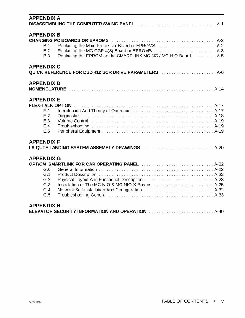
APPENDIX A DISASSEMBLING THE COMPUTER SWING PANEL . . . . . . . . . . . . . . . . . . . . . . . . . . . . . . . . A-1
APPENDIX BCHANGING PC BOARDS OR EPROMS . . . . . . . . . . . . . . . . . . . . . . . . . . . . . . . . . . . . . . . . . . A-2
B.1 Replacing the Main Processor Board or EPROMS . . . . . . . . . . . . . . . . . . . . . . . . A-2B.2 Replacing the MC-CGP-4(8) Board or EPROMS . . . . . . . . . . . . . . . . . . . . . . . . . A-3B.3 Replacing the EPROM on the SMARTLINK MC-NC / MC-NIO Board . . . . . . . . . A-5
APPENDIX CQUICK REFERENCE FOR DSD 412 SCR DRIVE PARAMETERS . . . . . . . . . . . . . . . . . . . . . . A-6
APPENDIX DNOMENCLATURE . . . . . . . . . . . . . . . . . . . . . . . . . . . . . . . . . . . . . . . . . . . . . . . . . . . . . . . . . . A-14
APPENDIX E FLEX-TALK OPTION . . . . . . . . . . . . . . . . . . . . . . . . . . . . . . . . . . . . . . . . . . . . . . . . . . . . . . . . A-17
E.1 Introduction And Theory of Operation . . . . . . . . . . . . . . . . . . . . . . . . . . . . . . . . A-17E.2 Diagnostics . . . . . . . . . . . . . . . . . . . . . . . . . . . . . . . . . . . . . . . . . . . . . . . . . . . . A-18E.3 Volume Control . . . . . . . . . . . . . . . . . . . . . . . . . . . . . . . . . . . . . . . . . . . . . . . . . A-19E.4 Troubleshooting . . . . . . . . . . . . . . . . . . . . . . . . . . . . . . . . . . . . . . . . . . . . . . . . . A-19E.5 Peripheral Equipment . . . . . . . . . . . . . . . . . . . . . . . . . . . . . . . . . . . . . . . . . . . . . A-19
APPENDIX FLS-QUTE LANDING SYSTEM ASSEMBLY DRAWINGS . . . . . . . . . . . . . . . . . . . . . . . . . . . . . A-20
APPENDIX GOPTION SMARTLINK FOR CAR OPERATING PANEL . . . . . . . . . . . . . . . . . . . . . . . . . . . . . A-22
G.0 General Information . . . . . . . . . . . . . . . . . . . . . . . . . . . . . . . . . . . . . . . . . . . . . . A-22G.1 Product Description . . . . . . . . . . . . . . . . . . . . . . . . . . . . . . . . . . . . . . . . . . . . . . A-22G.2 Physical Layout And Functional Description . . . . . . . . . . . . . . . . . . . . . . . . . . . . A-23G.3 Installation of The MC-NIO & MC-NIO-X Boards . . . . . . . . . . . . . . . . . . . . . . . . A-25G.4 Network Self-installation And Configuration . . . . . . . . . . . . . . . . . . . . . . . . . . . . A-32G.5 Troubleshooting General . . . . . . . . . . . . . . . . . . . . . . . . . . . . . . . . . . . . . . . . . . A-33
APPENDIX HELEVATOR SECURITY INFORMATION AND OPERATION . . . . . . . . . . . . . . . . . . . . . . . . . . A-40

• PRECAUTIONS & NOTES 42-02-4022vi
This page intentionally blank
42-02-4022 PRECAUTIONS & NOTES • vii
NOTE
WARNING
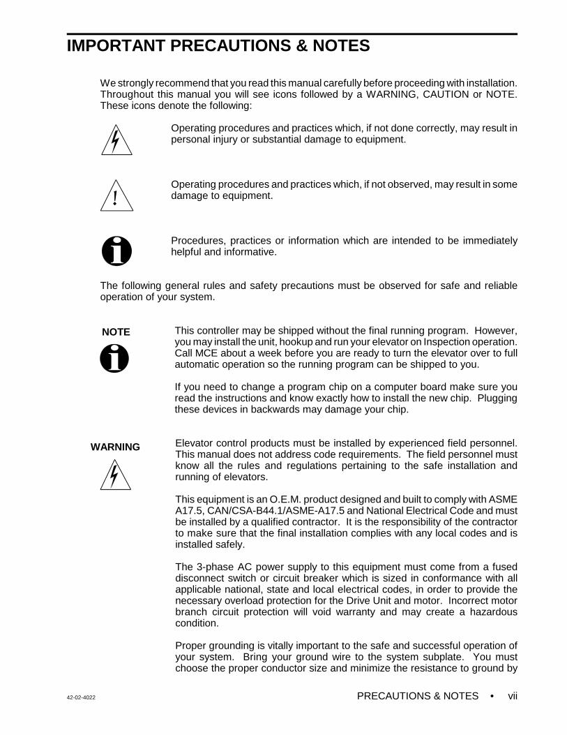
IMPORTANT PRECAUTIONS & NOTES
We strongly recommend that you read this manual carefully before proceeding with installation.Throughout this manual you will see icons followed by a WARNING, CAUTION or NOTE.These icons denote the following:
Operating procedures and practices which, if not done correctly, may result inpersonal injury or substantial damage to equipment.
Operating procedures and practices which, if not observed, may result in somedamage to equipment.
Procedures, practices or information which are intended to be immediatelyhelpful and informative.
The following general rules and safety precautions must be observed for safe and reliableoperation of your system.
This controller may be shipped without the final running program. However,you may install the unit, hookup and run your elevator on Inspection operation.Call MCE about a week before you are ready to turn the elevator over to fullautomatic operation so the running program can be shipped to you.
If you need to change a program chip on a computer board make sure youread the instructions and know exactly how to install the new chip. Pluggingthese devices in backwards may damage your chip.
Elevator control products must be installed by experienced field personnel.This manual does not address code requirements. The field personnel mustknow all the rules and regulations pertaining to the safe installation andrunning of elevators.
This equipment is an O.E.M. product designed and built to comply with ASMEA17.5, CAN/CSA-B44.1/ASME-A17.5 and National Electrical Code and mustbe installed by a qualified contractor. It is the responsibility of the contractorto make sure that the final installation complies with any local codes and isinstalled safely.
The 3-phase AC power supply to this equipment must come from a fuseddisconnect switch or circuit breaker which is sized in conformance with allapplicable national, state and local electrical codes, in order to provide thenecessary overload protection for the Drive Unit and motor. Incorrect motorbranch circuit protection will void warranty and may create a hazardouscondition.
Proper grounding is vitally important to the safe and successful operation ofyour system. Bring your ground wire to the system subplate. You mustchoose the proper conductor size and minimize the resistance to ground by

• PRECAUTIONS & NOTES 42-02-4022viii
CAUTION
NOTE
WARNING
using shortest possible routing. See National Electrical Code Article 250-95,or the related local applicable code.
Before applying power to the controller, physically check all the powerresistors and other components located in the resistor cabinet and inside thecontroller. Components loosened during shipment may cause damage. Pleasemake sure that all the safety relays on the SC-SB2K board are properlyseated in their sockets by pushing each relay into its socket.
You must not connect the output triacs directly to a hot bus (2, 3 or 4 bus).This can damage the triacs. PIs, direction arrows and terminals 40 & 42 areexamples of outputs that can be damaged this way. Note: miswiring terminal39 into 40 can damage the fire warning indicator triac.
Your HC-PCIO and HC-CI/O-E boards are equipped with quick disconnectterminals. During the original installation, you may want to remove theterminal connector, hook up your field wires to it, test it for no shorts to ground(1 bus) and to 2, 3 and 4 terminals before plugging these terminals back intothe PC boards.
Do not change drive parameters while the elevator is running. Incorrect valuesof drive parameters can cause erratic elevator operation.
ENVIRONMENTAL CONSIDERATIONS:
Keep the machine room clean. Controllers are generally in NEMA 1 enclosures. Do not installthe controller in a dusty area. Do not install the controller in a carpeted area. Keep roomtemperature between 32E F to 104E F (0E to 40E C). Avoid condensation on the equipment.Do not install the controller in a hazardous location and where excessive amounts of vapors orchemical fumes may be present. Make sure power line fluctuations are within + 10%.
CONTROLLER OR GROUP ENCLOSURES WITH AIR CONDITIONING
If your controller or group enclosure is equipped with an air conditioning unit, observe thefollowing precautions (failure to do so can result in water condensation inside the enclosure):
• Ensure the integrity of the NEMA 12 or 4 enclosure is maintained by using sealedknockouts and by sealing any holes created during installation.
• Do not run the air conditioner unit when the doors are open.
• To avoid damaging the compressor, if the air conditioner is turned off while it is running,wait at least five minutes before turning power on again.
• Observe the manufacture’s recommended maintenance and optimum thermostat settingof 75o F (see Operator’s Manual).
• Ensure the air conditioner unit’s drain hose remains open.
42-02-4022 PRECAUTIONS & NOTES • ix
LIMITED WARRANTY
Motion Control Engineering (manufacturer) warrants its products for a period of 15 months from the date ofshipment from its factory to be free from defects in workmanship and materials. Any defect appearing more than15 months from the date of shipment from the factory shall be deemed to be due to ordinary wear and tear.Manufacturer, however, assumes no risk or liability for results of the use of the products purchased from it,including, but without limiting the generality of the forgoing: (1) The use in combination with any electrical orelectronic components, circuits, systems, assemblies or any other material or equipment (2) Unsuitability of thisproduct for use in any circuit, assembly or environment. Purchasers’ rights under this warranty shall consist solelyof requiring the manufacturer to repair, or in manufacturer's sole discretion, replace free of charge, F.O.B. factory,any defective items received at said factory within the said 15 months and determined by manufacturer to bedefective. The giving of or failure to give any advice or recommendation by manufacturer shall not constitute anywarranty by or impose any liability upon the manufacturer. This warranty constitutes the sole and exclusiveremedy of the purchaser and the exclusive liability of the manufacturer, AND IN LIEU OF ANY AND ALL OTHERWARRANTIES, EXPRESSED, IMPLIED, OR STATUTORY AS TO MERCHANTABILITY, FITNESS, FORPURPOSE SOLD, DESCRIPTION, QUALITY PRODUCTIVENESS OR ANY OTHER MATTER. In no event willthe manufacturer be liable for special or consequential damages or for delay in performance of this warranty.
Products that are not manufactured by MCE (such as drives, CRT's, modems, printers, etc.) are not coveredunder the above warranty terms. MCE, however, extends the same warranty terms that the original manufacturerof such equipment provide with their product (refer to the warranty terms for such products in their respectivemanual).
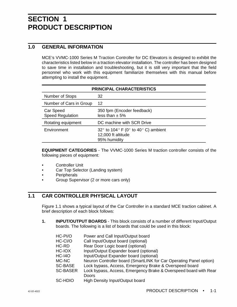
42-02-4022 PRODUCT DESCRIPTION • 1-1
SECTION 1PRODUCT DESCRIPTION
1.0 GENERAL INFORMATION
MCE’s VVMC-1000 Series M Traction Controller for DC Elevators is designed to exhibit thecharacteristics listed below in a traction elevator installation. The controller has been designedto save time in installation and troubleshooting, but it is still very important that the fieldpersonnel who work with this equipment familiarize themselves with this manual beforeattempting to install the equipment.
PRINCIPAL CHARACTERISTICS
Number of Stops 32
Number of Cars in Group 12
Car SpeedSpeed Regulation
350 fpm (Encoder feedback)less than ± 5%
Rotating equipment DC machine with SCR Drive
Environment 32E to 104E F (0E to 40E C) ambient12,000 ft altitude95% humidity
EQUIPMENT CATEGORIES - The VVMC-1000 Series M traction controller consists of thefollowing pieces of equipment:
• Controller Unit• Car Top Selector (Landing system)• Peripherals• Group Supervisor (2 or more cars only)
1.1 CAR CONTROLLER PHYSICAL LAYOUT
Figure 1.1 shows a typical layout of the Car Controller in a standard MCE traction cabinet. Abrief description of each block follows:
1. INPUT/OUTPUT BOARDS - This block consists of a number of different Input/Outputboards. The following is a list of boards that could be used in this block:
HC-PI/O Power and Call Input/Output boardHC-CI/O Call Input/Output board (optional)HC-RD Rear Door Logic board (optional)HC-IOX Input/Output Expander board (optional)HC-I4O Input/Output Expander board (optional)MC-NC Neuron Controller board (SmartLINK for Car Operating Panel option)SC-BASE Lock bypass, Access, Emergency Brake & Overspeed boardSC-BASER Lock bypass, Access, Emergency Brake & Overspeed board with Rear
DoorsSC-HDIO High Density Input/Output board
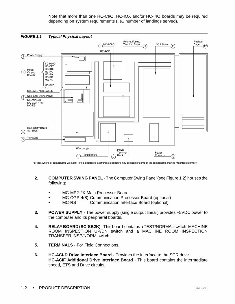
• PRODUCT DESCRIPTION 42-02-40221-2
Note that more than one HC-CI/O, HC-IOX and/or HC-I4O boards may be requireddepending on system requirements (i.e., number of landings served).
FIGURE 1.1 Typical Physical Layout
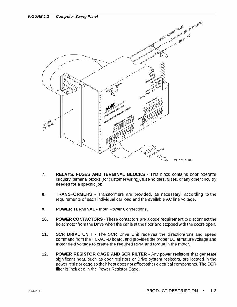
2. COMPUTER SWING PANEL - The Computer Swing Panel (see Figure 1.2) houses thefollowing:
• MC-MP2-2K Main Processor Board• MC-CGP-4(8) Communication Processor Board (optional)• MC-RS Communication Interface Board (optional)
3. POWER SUPPLY - The power supply (single output linear) provides +5VDC power tothe computer and its peripheral boards.
4. RELAY BOARD (SC-SB2K) - This board contains a TEST/NORMAL switch, MACHINEROOM INSPECTION UP/DN switch and a MACHINE ROOM INSPECTIONTRANSFER INSP/NORM switch.
5. TERMINALS - For Field Connections.
6. HC-ACI-D Drive Interface Board - Provides the interface to the SCR drive.HC-ACIF Additional Drive Interface Board - This board contains the intermediatespeed, ETS and Drive circuits.
42-02-4022 PRODUCT DESCRIPTION • 1-3
FIGURE 1.2 Computer Swing Panel
7. RELAYS, FUSES AND TERMINAL BLOCKS - This block contains door operatorcircuitry, terminal blocks (for customer wiring), fuse holders, fuses, or any other circuitryneeded for a specific job.
8. TRANSFORMERS - Transformers are provided, as necessary, according to therequirements of each individual car load and the available AC line voltage.
9. POWER TERMINAL - Input Power Connections.
10. POWER CONTACTORS - These contactors are a code requirement to disconnect thehoist motor from the Drive when the car is at the floor and stopped with the doors open.
11. SCR DRIVE UNIT - The SCR Drive Unit receives the direction(run) and speedcommand from the HC-ACI-D board, and provides the proper DC armature voltage andmotor field voltage to create the required RPM and torque in the motor.
12. POWER RESISTOR CAGE AND SCR FILTER - Any power resistors that generate
significant heat, such as door resistors or Drive system resistors, are located in thepower resistor cage so their heat does not affect other electrical components. The SCRfilter is included in the Power Resistor Cage.
• PRODUCT DESCRIPTION 42-02-40221-4
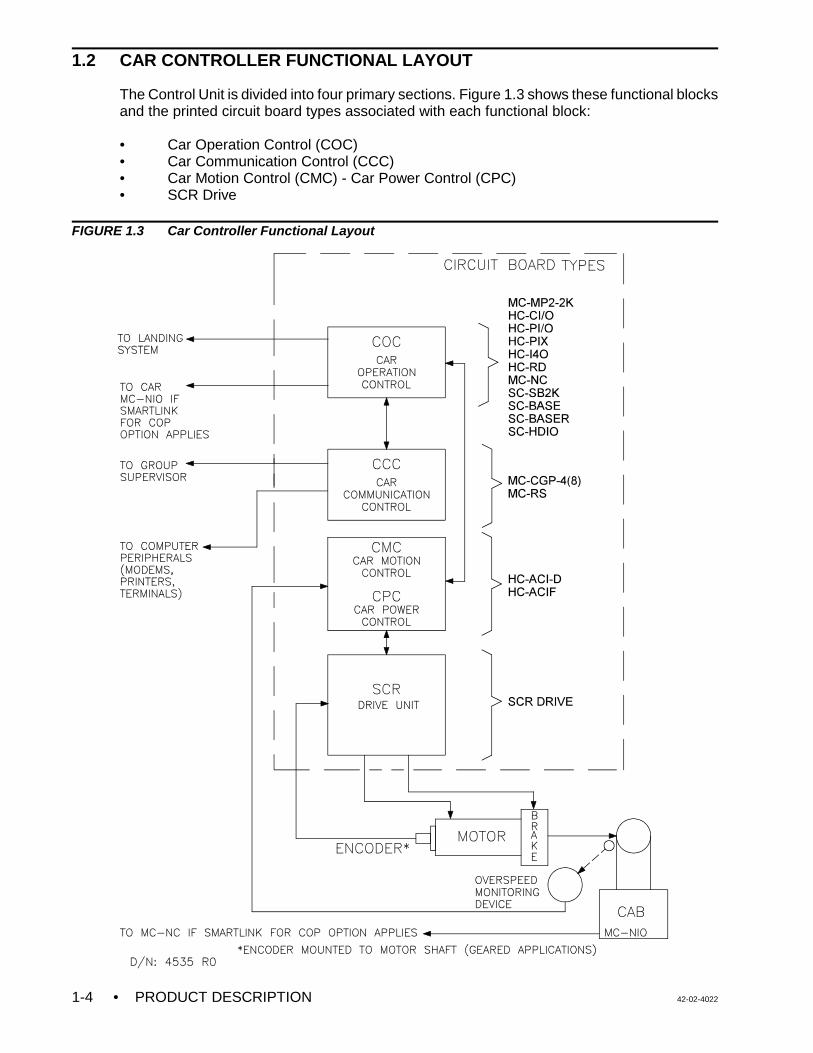
1.2 CAR CONTROLLER FUNCTIONAL LAYOUT
The Control Unit is divided into four primary sections. Figure 1.3 shows these functional blocksand the printed circuit board types associated with each functional block:
• Car Operation Control (COC)• Car Communication Control (CCC)• Car Motion Control (CMC) - Car Power Control (CPC)• SCR Drive
FIGURE 1.3 Car Controller Functional Layout
42-02-4022 PRODUCT DESCRIPTION • 1-5
CAR OPERATION CONTROL (COC) - This functional block covers logical car operation andsafety monitoring. An example of logical operation would be operation of the doors andresponse to hall and car call demands or special operations such as Inspection/Access, FireService, etc. Additional special operations are provided as required per specifications.
The heart of the COC is the SC-SB2K Main Relay board, which makes it possible to move thecar without computers and satisfies code-required safety functions and redundant relay backupfunctions. All computer functions can fail in an ON condition and the car will not move if thedoor lock circuits are not closed. Except for calls, most of the individual elevator inputs andoutputs are handled through the Main Relay board and are routed to the HC-PI/O board, whichis the main interface to the computer.
Provisions for eight position indicator outputs are on the HC-PI/O board. If additional positionindicators are required, HC-PIX boards are added. If independent (walk-through) rear doors arerequired, the HC-RD board acts as the interface between the computer and the Rear DoorRelay board, which handles all functions associated with the rear doors. Some additional inputsand outputs, such as load weighers, are handled through the HC-IOX or HC-I4O board.
Hall calls are interfaced to the computer through the HC-CI/O boards which can handle up to16 calls per board. Car calls are interfaced through the HC-CI/O boards or the MC-NC boardif the controller is equipt with the SmartLINK for Car Operating Panel option. Therefore, all theinput/output boards (HC-PI/O, HC-PIX, HC-RD, HC-IOX, HC-I4O, HC-CI/O and MC-NC) actas the interface between the MC-MP2-2K Main Computer board and the user. Theseinput/output boards are linked to the Main Computer board through the ribbon cable attachedto the MC-MP2-2K board, which plugs into the HC-PI/O board. The Main Computer boardcontains the main elevator logic program.
CAR COMMUNICATION CONTROL (CCC) - This functional block coordinates the flow ofinformation between the car controller and other equipment such as terminals, modems,printers and the Group Supervisor in an M3 Group System.
CAR MOTION CONTROL (CMC) - Car Motion Control (CMC) develops the speed commandwhich dictates the car's speed. The speed signal is in the form of step input signals which areapplied to the drive unit. The drive responds to the commanded step inputs and runs theelevator at predefined speed settings stored in the drive unit. The CMC also providesInspection/Leveling Overspeed (ILO) monitoring and Emergency Terminal Switch (ETS)monitoring. These functions are covered by the following devices:
• HC-ACI-D Drive Interface board• HC-ACIF Additional Flux Vector Drive Interface board
The HC-ACI-D board creates the speed command, controls the brake, monitors overspeedconditions and is the interface between the COC, CPC and the power equipment such as thebrake, SCR Drive Unit and supporting devices.
CAR POWER CONTROL (CPC) - SCR DRIVE - Car Power Control (CPC) receives thedirection command and speed signal from the CMC and produces the necessary outputs to therotating equipment to achieve the desired elevator movement. The SCR Drive Unit receives thedirection(run) and speed command from the HC-ACI-D board, and provides the proper DCarmature voltage and motor field voltage to create the required RPM and torque in the motor.
• PRODUCT DESCRIPTION 42-02-40221-6
1.2.1 CAR OPERATION CONTROL (COC) COMPONENTS
Car Operation Control involves such things as door operation, response to hall and car calls,and special operations such as Inspection/Access and Fire Service. The following boards areinvolved in the COC functions:
C MC-MP2-2K, Main Processor BoardC SC-SB2K, Main Relay BoardC SC-HDIO, High Density I/O BoardC SC-BASE, Lock Bypass, Access, Overspeed and Emergency Brake BoardC SC-BASER, Lock Bypass, Access, Overspeed and Emergency Brake Board
with Rear DoorsC HC-PI/O, Power Input / Output BoardC HC-PIX, Position Indicator BoardC HC-CI/O, Call Input / Output BoardC HC-IOX, Input / Output Expander BoardC HC-I4O, Input / Output Expander BoardC MC-NC, Neuron Controller Board
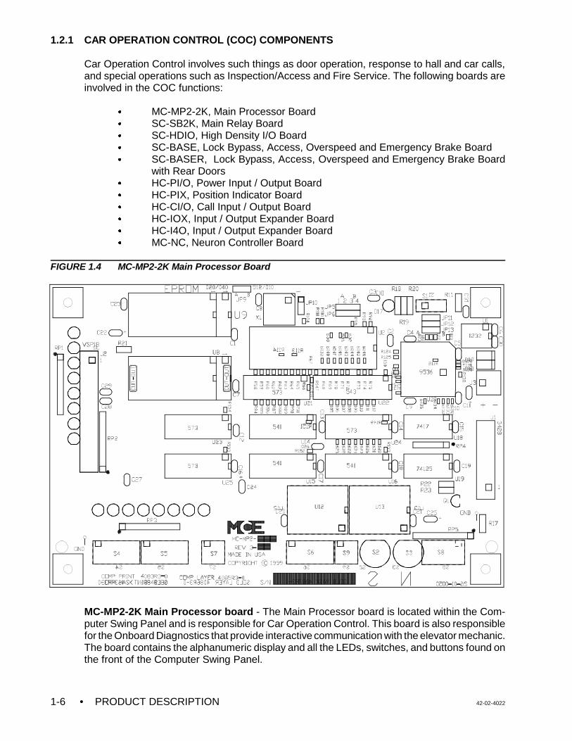
FIGURE 1.4 MC-MP2-2K Main Processor Board
MC-MP2-2K Main Processor board - The Main Processor board is located within the Com-puter Swing Panel and is responsible for Car Operation Control. This board is also responsiblefor the Onboard Diagnostics that provide interactive communication with the elevator mechanic.The board contains the alphanumeric display and all the LEDs, switches, and buttons found onthe front of the Computer Swing Panel.
42-02-4022 PRODUCT DESCRIPTION • 1-7
MAIN PROCESSOR SUBSYSTEM - This subsystem consists of many different input/outputcircuit boards. The layout and arrangement of these boards may vary from controller tocontroller. The following boards are typically included:
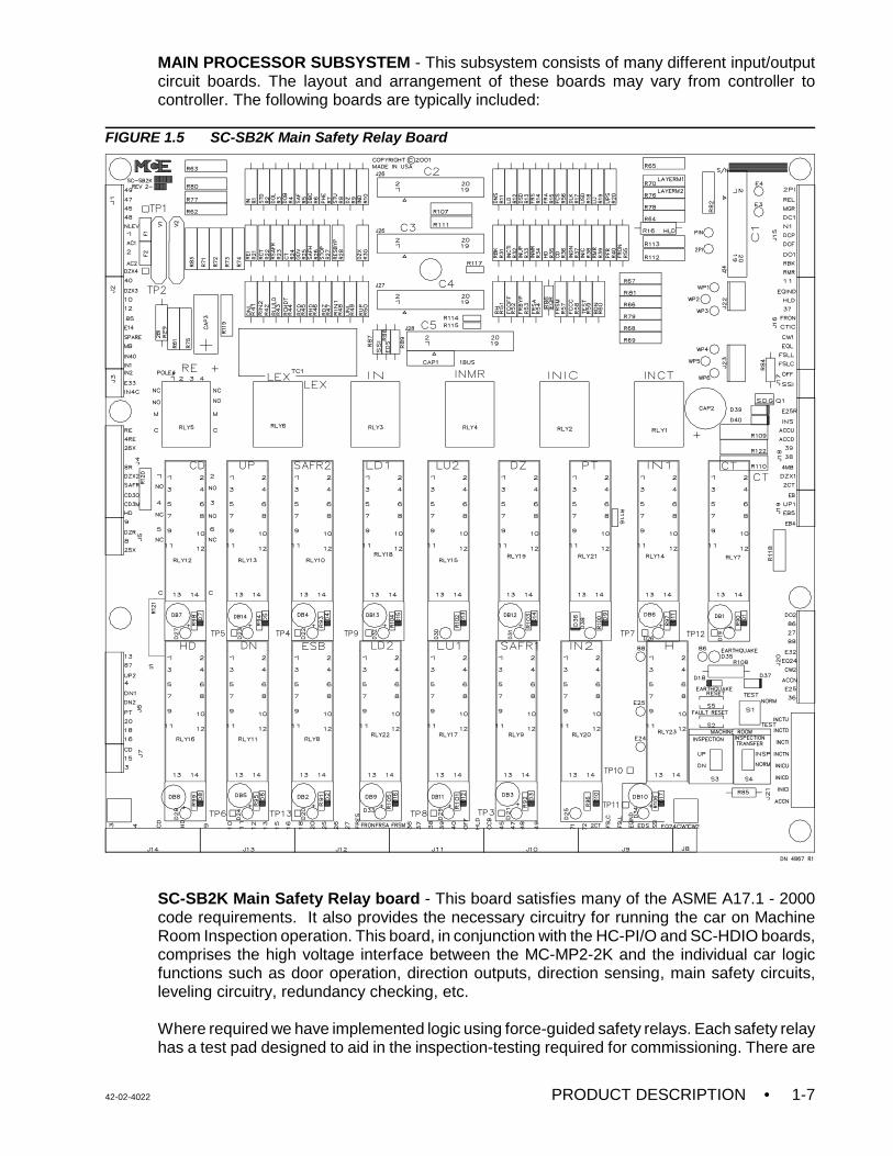
FIGURE 1.5 SC-SB2K Main Safety Relay Board
SC-SB2K Main Safety Relay board - This board satisfies many of the ASME A17.1 - 2000code requirements. It also provides the necessary circuitry for running the car on MachineRoom Inspection operation. This board, in conjunction with the HC-PI/O and SC-HDIO boards,comprises the high voltage interface between the MC-MP2-2K and the individual car logicfunctions such as door operation, direction outputs, direction sensing, main safety circuits,leveling circuitry, redundancy checking, etc.
Where required we have implemented logic using force-guided safety relays. Each safety relayhas a test pad designed to aid in the inspection-testing required for commissioning. There are
• PRODUCT DESCRIPTION 42-02-40221-8
terminals at the bottom of the board for field wiring. This board, located in the upper right cornerof the controller cabinet, includes the MACHINE ROOM INSPECTION TRANSFERINSP/NORM switch, the MACHINE ROOM INSPECTION UP/DN switch, TEST/NORM andpushbuttons for Earthquake and Fault Reset.
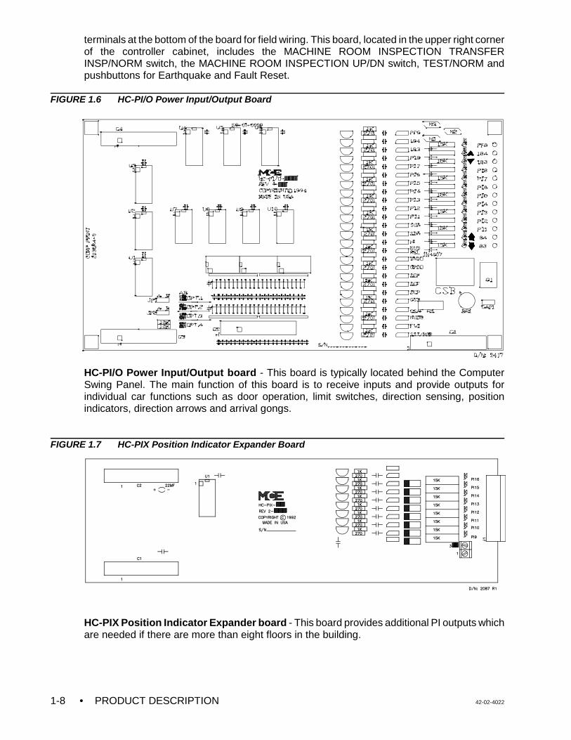
FIGURE 1.6 HC-PI/O Power Input/Output Board
HC-PI/O Power Input/Output board - This board is typically located behind the ComputerSwing Panel. The main function of this board is to receive inputs and provide outputs forindividual car functions such as door operation, limit switches, direction sensing, positionindicators, direction arrows and arrival gongs.
FIGURE 1.7 HC-PIX Position Indicator Expander Board
HC-PIX Position Indicator Expander board - This board provides additional PI outputs whichare needed if there are more than eight floors in the building.
42-02-4022 PRODUCT DESCRIPTION • 1-9
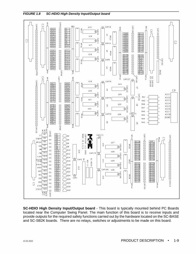
FIGURE 1.8 SC-HDIO High Density Input/Output board
SC-HDIO High Density Input/Output board - This board is typically mounted behind PC Boardslocated near the Computer Swing Panel. The main function of this board is to receive inputs andprovide outputs for the required safety functions carried out by the hardware located on the SC-BASEand SC-SB2K boards. There are no relays, switches or adjustments to be made on this board.
• PRODUCT DESCRIPTION 42-02-40221-10
FIGURE 1.9 SC-BASE Bypass, Access, Overspeed and Emergency Brake board
SC-BASE Bypass, Access, Overspeed and Emergency Brake board - This board has thenecessary relays and hardware that is used to enable door lock bypass operation, inspection access,emergency brake activation and overspeed monitoring for access, inspection, leveling and emergencyterminal speed limiting. Switches included on the board are for car and hoistway door lock bypass aswell as emergency brake reset. Rear door bypass switches, if present, are located on the SC-BASER.
42-02-4022 PRODUCT DESCRIPTION • 1-11
FIGURE 1.10 SC-BASER Bypass, Access, Overspeed, Emergency Brake Board with Rear Doors
SC-BASER Lock Bypass, Access, Overspeed, Emergency Brake Board with Rear Doors - Thisboard is used in place of the SC-BASE board when the job has rear doors.
• PRODUCT DESCRIPTION 42-02-40221-12
FIGURE 1.11 HC-CI/O Call Input/Output Board
HC-CI/O Call Input/Output board - This board processes hall call and car call inputs, callacknowledgment outputs, and displays the status of each call.
FIGURE 1.12 HC-IOX Input/Output Expander Board
HC-IOX / HC-I4O Input/Output Expander board - The HC-IOX is a multipurpose input/outputboard (Figure 1.12). Some installations have the HC-I4O board instead (Figure 1.13. Itsfunctions are similar to the HC-IOX and HC-IOX-A.
FIGURE 1.13 HC-I4O Input/Output Expander Board
42-02-4022 PRODUCT DESCRIPTION • 1-13
HC-RD Rear Door board - This board provides the necessary logic required when anadditional independent rear door is present (board not pictured).
MC-NC Neuron Controller board (optional) - Control board for the SmartLINK for CarOperating Panel option (board not pictured). See Appendix G, Option SmartLINK for CarOperating Panel if applicable.
MC-NIO Neuron Input/Output board (optional) (board not pictured) - Located in the car, theMC-NIO board transfers COP signal values to and from the car controller node as networkpackets. COP signals include call buttons, door open button, door close button, call lockouts,etc. See Appendix G, Option SmartLINK for Car Operating Panel if applicable.
1.2.2 CAR OPERATION CONTROL (COC) INPUTS AND OUTPUTS
COC INPUTS - This section describes the main signals received by the MC-MP2-2K MainProcessor board.
The COC module is responsible for the “logical operation” of the elevator control system. Forexample, the COC may decide that the car should travel from one floor to another in responseto a car call, but leaves the “speed control” (acceleration, deceleration, etc.) to the CMCmodule. The fundamental inputs that are required for the logical control of the elevator cometo the Main Processor board through three boards: the SC-HDIO (high density I/O), the HC-PI/O board (power input/output board) and the HC-CI/O board (call input/output board). EachVVMC-1000 control system has one HC-PI/O board, and as many HC-CI/O boards as arerequired to accommodate the number of calls in the particular installation. Additional“miscellaneous” inputs come to the Main Processor board through the HC-IOX or HC-I4O board(I/O expansion board, also as many as needed).
Primary Power inputs - HC-PI/O board
C Door signals - The HC-PI/O board receives the door-related signals through the mainrelay board (SC-SB2K). The door related signals include the door reopening devices(photo eye, safe edge), car operating panel buttons (door open button, door closebutton), and the door position contacts (door open limit, door lock).
C Landing system signals - The HC-PI/O board receives some of the signals generatedby the landing system through the SC-SB2K Main Relay board. The landing systemsignals read by the COC module are the door zone, level up and level down signals.
C Operational mode signals - The HC-PI/O board receives a few of the operational andsafety mode signals through the SC-SB2K Main Relay board. These signals include thesafety string status, the inspection operation status, and the independent service status.Additionally, some of the fire service signals are also received by the HC-PI/O boardthrough the relay board (fire sensors, in-car fire service switch).
C Direction sensing inputs - Two direction sensing inputs (up sense and down sense)are read by the COC processor, again through the HC-PI/O and SC-SB2K, and areused to process the car position indicator logic and motor protection timing logic.
Call inputs (car call and hall call) - HC-CI/O board
The call buttons and call indicators are wired to the control system and read by the COCprocessor through the call board(s) (HC-CI/O and/or MC-NC). The connection to the HC-CI/Oboard is a single wire connection for both the button and the indicator (the terminal acts as bothan input and output terminal). In multi-car group arrangements, “system” hall calls are wired to
• PRODUCT DESCRIPTION 42-02-40221-14
the Group Supervisor (also to HC-CI/O boards), but “swing car” hall calls are wired to the callboard of the individual car controller, along with the car calls.
COC OUTPUTS - This section describes the main signals generated by the MC-MP2-2K MainProcessor board.
The fundamental outputs that are required for the logical control of the elevator emerge fromthe Main Processor board through the same two boards described above: the HC-PI/O board(power input/output board) and the HC-CI/O board (call input/output board). Additional“miscellaneous” outputs emerge from the Main Processor board through the HC-IOX or HC-I4OI/O Expansion boards, as many as are needed, and some “specialty” output boards which maybe used to drive specific devices.
Primary Power Outputs - HC-PI/O board
C Position indicators, direction arrows, and arrival fixture signals - Eight positionindicator outputs are provided on the HC-PI/O board. Should the particular installationhave more than eight landings, additional position indicator outputs are providedthrough the use of HC-PIX boards (position indicator expansion boards). The up anddown direction arrow indicators and the up and down arrival lantern outputs are alsoprovided on the HC-PI/O board. The output terminals for these indicator outputs arelocated on the HC-PI/O board.
C Fire service operation signals - Two outputs associated with fire service operation aregenerated on the HC-PI/O board, and are routed through the main relay board. The firewarning indicator output generates the visual/audible signal in the elevator during firephase I recall, and the in-car stop switch bypass output is used for rendering the in-carstop switch inoperative, also during fire phase I recall.
C Door control signals - Four signals are generated by the COC module to control theoperation of the doors. These outputs are generated on the HC-PI/O board, but arerouted through the main relay board for connection to external relays. These signals arethe door open function, door close function, door close power, and nudging outputs.Should the installation have a floor with both front and rear openings, a rear door logicboard (HC-RD) is used to generate the corresponding outputs for the rear door.
C Car movement signals - Four signals are generated by the COC module to performthe logical control of car movement. In hydraulic applications these signals directlycontrol the valve solenoids to cause the car to move up and down at high and lowspeeds. In VVMC-1000 applications, however, these outputs are read by the CMCmodule, which applies the proper speed input to the SCR drive. The four signalsgenerated by the COC are up direction, down direction, high speed and relevel speed.As an example, a high speed run in the up direction would be requested by the COCby generating the high speed and up direction outputs.
Call outputs (car call and hall call) - HC-CI/O board
The call button indicators are wired to the control system and generated by the COC modulethrough the HC-CI/O call board(s), or MC-NC and MC-NIO boards with the SmartLINK for COPoption (see Appendix G). The connection to the HC-CI/O call board is a single wire connectionfor both the indicator and the call button (the terminal acts as both an input and outputterminal). In multi-car group arrangements, “system” hall calls are wired to the GroupSupervisor, but “swing car” hall calls are wired to the call board of the individual car controller,along with the car calls.
42-02-4022 PRODUCT DESCRIPTION • 1-15
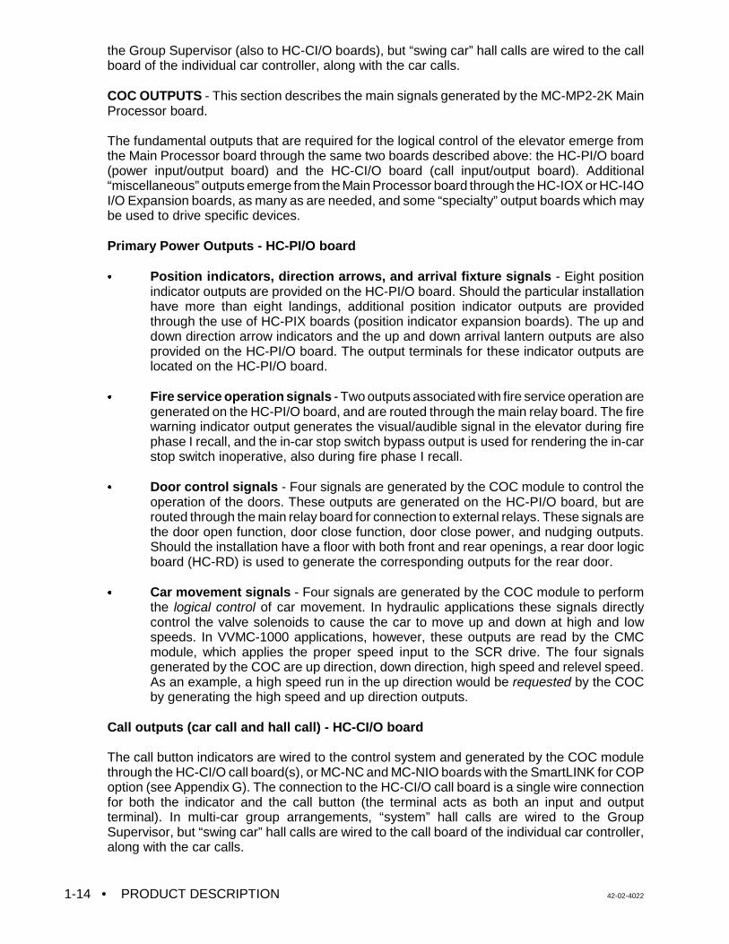
1.2.3 CAR COMMUNICATION CONTROL (CCC) COMPONENTS
The flow of information between the car controller and other equipment such as terminals,modems, printers or Group Supervisor is controlled by the following boards:
• MC-CGP-4(8), Communication Processor Board (optional)C MC-RS, Communication Interface Board (optional)
FIGURE 1.14 MC-CGP-4(8) Communication Processor Board
MC-CGP-4(8) Communication Processor Board - This board contains a very powerful 32-bitembedded RISC microcontroller, and is located behind the Main Processor board inside theComputer Swing Panel. The primary function of this board is to co-ordinate the flow ofinformation between the car controller and other equipment and peripherals, such as a CRT,modem, printer or a PC for diagnostics and data logging.
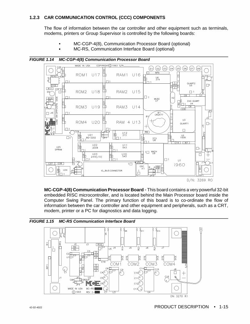
FIGURE 1.15 MC-RS Communication Interface Board
• PRODUCT DESCRIPTION 42-02-40221-16
MC-RS Communication Interface Board - This board provides a high-speed RS-422 seriallink between the individual car controller and the M3 Group Supervisor. It also provides fourindustry standard RS-232C serial ports to interface the car controller with a standard computeror data terminal, such as a printer, modem or CRT terminal.
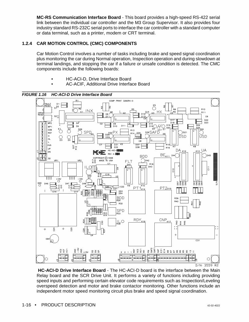
1.2.4 CAR MOTION CONTROL (CMC) COMPONENTS
Car Motion Control involves a number of tasks including brake and speed signal coordinationplus monitoring the car during Normal operation, Inspection operation and during slowdown atterminal landings, and stopping the car if a failure or unsafe condition is detected. The CMCcomponents include the following boards:
• HC-ACI-D, Drive Interface Board• AC-ACIF, Additional Drive Interface Board
FIGURE 1.16 HC-ACI-D Drive Interface Board
HC-ACI-D Drive Interface Board - The HC-ACI-D board is the interface between the MainRelay board and the SCR Drive Unit. It performs a variety of functions including providingspeed inputs and performing certain elevator code requirements such as Inspection/Levelingoverspeed detection and motor and brake contactor monitoring. Other functions include anindependent motor speed monitoring circuit plus brake and speed signal coordination.
42-02-4022 PRODUCT DESCRIPTION • 1-17
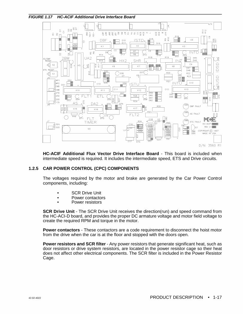
FIGURE 1.17 HC-ACIF Additional Drive Interface Board
HC-ACIF Additional Flux Vector Drive Interface Board - This board is included whenintermediate speed is required. It includes the intermediate speed, ETS and Drive circuits.
1.2.5 CAR POWER CONTROL (CPC) COMPONENTS
The voltages required by the motor and brake are generated by the Car Power Controlcomponents, including:
• SCR Drive Unit• Power contactors• Power resistors
SCR Drive Unit - The SCR Drive Unit receives the direction(run) and speed command fromthe HC-ACI-D board, and provides the proper DC armature voltage and motor field voltage tocreate the required RPM and torque in the motor.
Power contactors - These contactors are a code requirement to disconnect the hoist motorfrom the drive when the car is at the floor and stopped with the doors open.
Power resistors and SCR filter - Any power resistors that generate significant heat, such asdoor resistors or drive system resistors, are located in the power resistor cage so their heatdoes not affect other electrical components. The SCR filter is included in the Power ResistorCage.
• PRODUCT DESCRIPTION 42-02-40221-18
1.2.6 TYPICAL SEQUENCE OF OPERATION
To become familiar with the overall sequence of operation of this controller, we begin with a carcall input and follow the signals as they progress through various parts of the control system.
A car call is registered by grounding an input on the HC-CI/O board or, with SmartLINK forCOP, by serial data sent from the MC-NIO board in the COP to the MC-NC board in thecontroller. On the HC-CI/O board the 120VAC signal is converted to a + 5V logic signal and isthen read by the MC-MP2-2K Main Computer board. The Main Computer board acknowledgesthis signal by sending a logic signal back to the HC-CI/O board which then turns on a triac toilluminate the call registered light in the car panel and an LED on the HC-CI/O board. With theSmartLINK for COP option the Main Computer sends data to the MC-NC board which, in turn,sends serial data to the MC-NIO board in the COP. The MC-NIO board then turns ON the callregistered light in the COP.
The Main Computer board determines where the call is in relation to the car position and sendsa direction arrow signal to the HC-PI/O board, which operates an up or down arrow triac output.This illuminates the correct direction arrow in the car position indicator. No further action cantake place unless additional conditions are met. Then, if the doors are closed, the MainComputer board sends the correct direction output signal to the HC-PI/O board, which operatesthe correct direction triac. This signal is sent to the SC-SB2K Main Relay board which energizesthe direction pilot relays. This direction signal then goes to the HC-ACI-D board and to one ormore auxiliary running relays. The direction and high speed commands originate from the MainComputer board through the HC-PI/O and the Main Relay board. The CMC is ready to lift thebrake and to provide control to the SCR Drive Unit in response to a speed command providedby the CMC.
In summary, the call signal entered the COC was processed into direction and high speedacceleration sequence commands. The SCR speed command and brake signals are thencreated by the CMC and the CPC moves the elevator according to the commanded speed.
42-02-4022 PRODUCT DESCRIPTION • 1-19
1.3 LANDING SYSTEMS
There are two different types of landing systems that can be used with VVMC-1000-SCRcontrollers, depending on the customer's preference: LS-STANx-2K and LS-QUTE-X-2K.These landing systems are discussed separately throughout this manual.
1.3.1 LS-STANx-2K
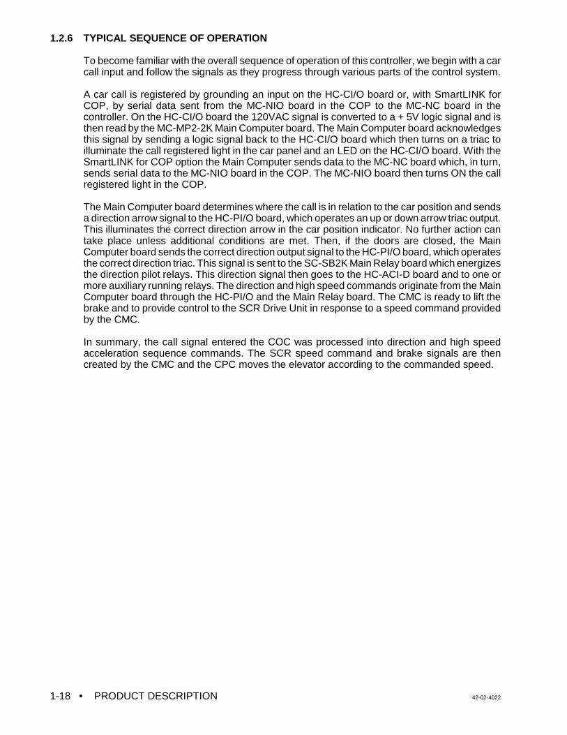
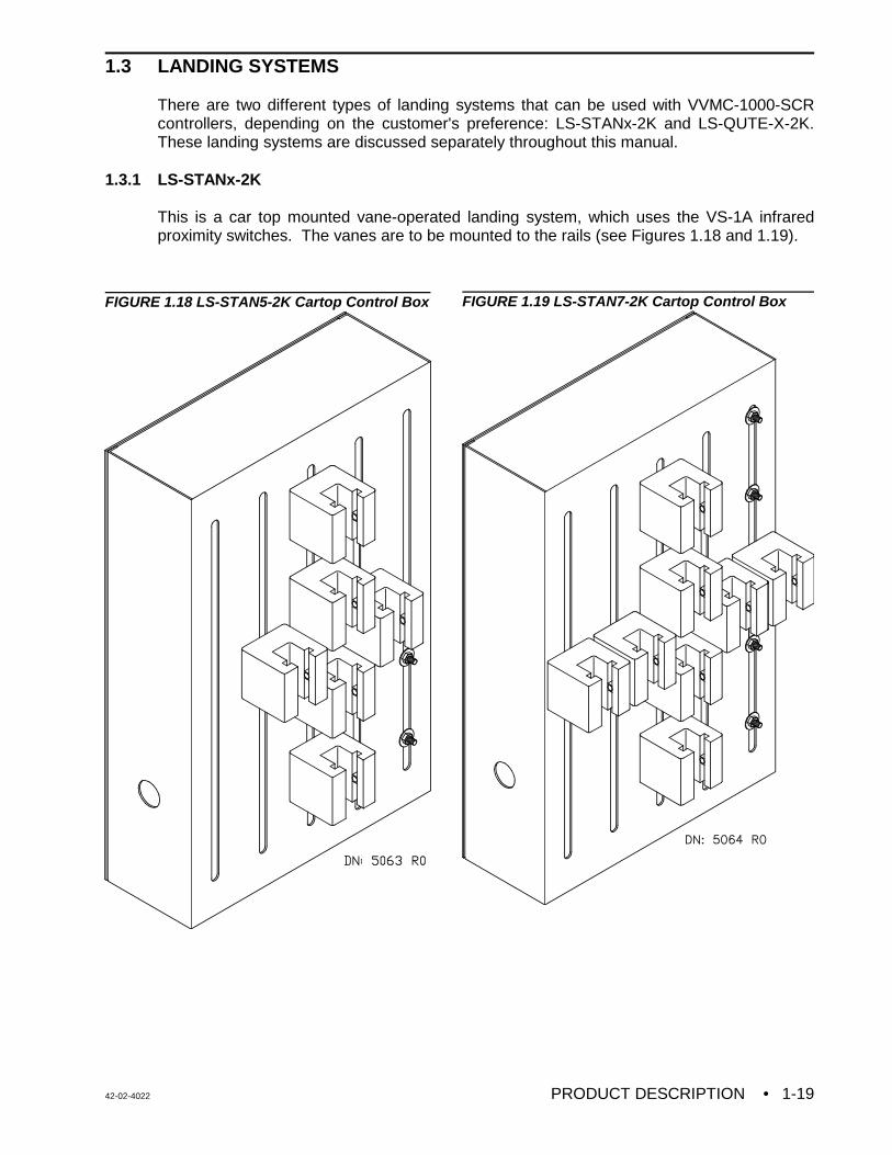
This is a car top mounted vane-operated landing system, which uses the VS-1A infraredproximity switches. The vanes are to be mounted to the rails (see Figures 1.18 and 1.19).
FIGURE 1.18 LS-STAN5-2K Cartop Control Box FIGURE 1.19 LS-STAN7-2K Cartop Control Box
• PRODUCT DESCRIPTION 42-02-40221-20
1.3.2 LS-QUTE-X-2K
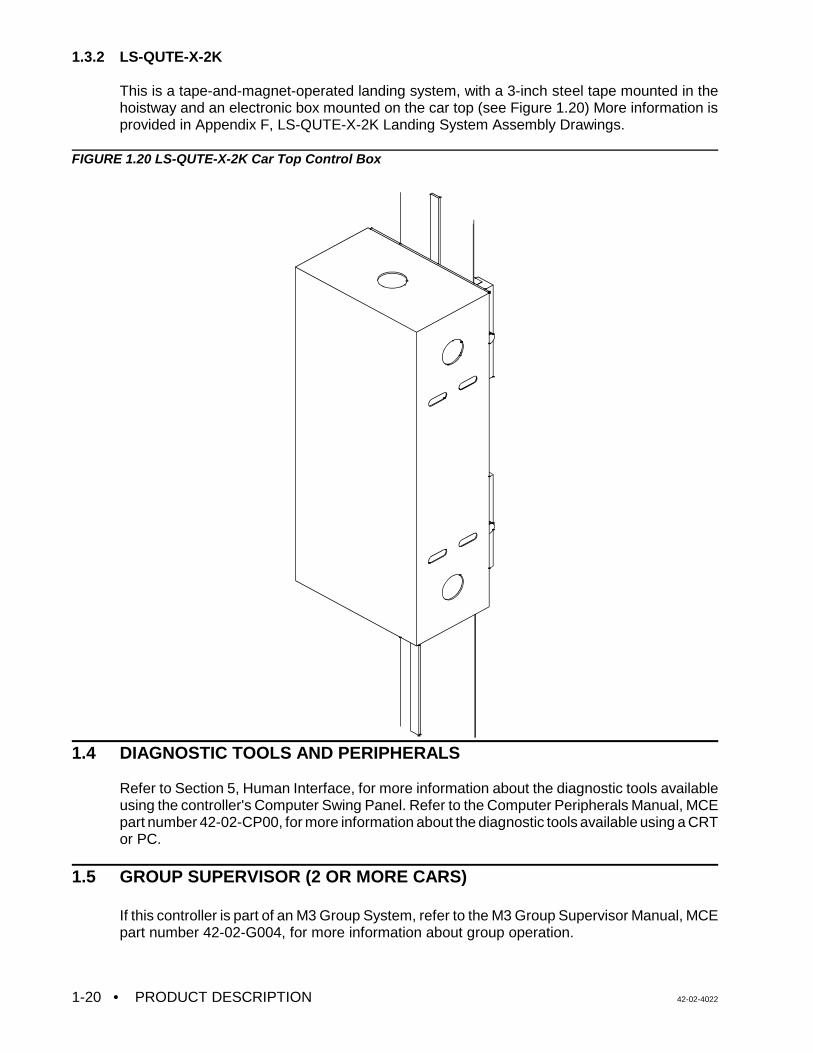
This is a tape-and-magnet-operated landing system, with a 3-inch steel tape mounted in thehoistway and an electronic box mounted on the car top (see Figure 1.20) More information isprovided in Appendix F, LS-QUTE-X-2K Landing System Assembly Drawings.
FIGURE 1.20 LS-QUTE-X-2K Car Top Control Box
1.4 DIAGNOSTIC TOOLS AND PERIPHERALS
Refer to Section 5, Human Interface, for more information about the diagnostic tools availableusing the controller's Computer Swing Panel. Refer to the Computer Peripherals Manual, MCEpart number 42-02-CP00, for more information about the diagnostic tools available using a CRTor PC.
1.5 GROUP SUPERVISOR (2 OR MORE CARS)
If this controller is part of an M3 Group System, refer to the M3 Group Supervisor Manual, MCEpart number 42-02-G004, for more information about group operation.
42-02-4022 INSTALLATION • 2-1
SECTION 2INSTALLATION
2.0 GENERAL INFORMATION
This section contains important instructions and recommendations pertaining to site selection,environmental considerations, wiring guidelines and other factors that will ensure a successfulinstallation.
2.0.1 SITE SELECTION
In choosing a proper location for the control equipment, the factors listed below should beconsidered.
• Provide adequate working space for comfort and efficiency.
• Mount the controller in a logical location, taking into consideration the location of otherequipment in the machine room and proper routing of electrical power and controlwiring. Note that MCE controllers do not require rear access.
• Do not install equipment in a hazardous location.
• Provide space for future expansion, if possible.
• Install a telephone in the machine room. Remote diagnostics are available via thetelephone which make start-up and adjustment assistance easier to obtain.
• If any areas in the machine room are subject to vibration, they should be avoided orreinforced to prevent equipment from being adversely affected.
• Provide adequate lighting for the control cabinets and machines. A good working spacesuch as a workbench or table should also be provided.
• The location of the Drive Isolation Transformer is flexible, however, wiring is reducedif it is located near the controller.
2.0.2 ENVIRONMENTAL CONSIDERATIONS
The following are some important environmental considerations that will help to provide for thelongevity of the elevator equipment and reduce maintenance requirements.
• The ambient temperature should not exceed 32E to 104E Fahrenheit (0E - 40E Celsius).Higher ambient temperatures are possible, but not recommended because it willshorten the life of the equipment. Adequate ventilation and possibly air conditioning maybe required.
• The air in the machine room should be free of excessive dust, corrosive atmosphere orexcessive moisture to avoid condensation. A NEMA 4 or NEMA 12 enclosure wouldhelp meet these requirements. If open windows exist in the machine room, it ispreferable to place cabinets away from these windows so that severe weather does notdamage the equipment.
• INSTALLATION 42-02-40222-2
• High levels of radio frequency (RF) radiation from nearby sources may causeinterference to the computers and other parts of the control system. Using a hand-heldcommunication device in close proximity to the computers may also cause interference.
• Power line fluctuation should not be greater than ±10%.
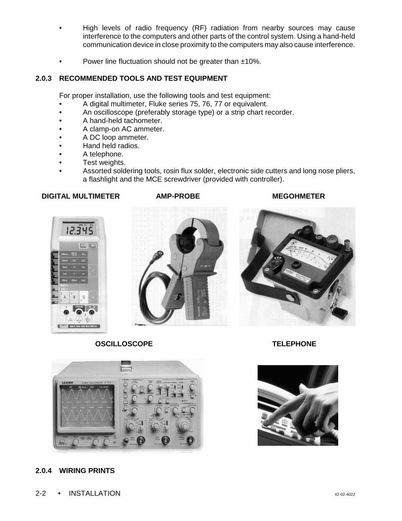
2.0.3 RECOMMENDED TOOLS AND TEST EQUIPMENT
For proper installation, use the following tools and test equipment:• A digital multimeter, Fluke series 75, 76, 77 or equivalent.• An oscilloscope (preferably storage type) or a strip chart recorder.• A hand-held tachometer.• A clamp-on AC ammeter.• A DC loop ammeter.• Hand held radios.• A telephone.• Test weights.• Assorted soldering tools, rosin flux solder, electronic side cutters and long nose pliers,
a flashlight and the MCE screwdriver (provided with controller).
DIGITAL MULTIMETER AMP-PROBE MEGOHMETER
OSCILLOSCOPE TELEPHONE
2.0.4 WIRING PRINTS
42-02-4022 INSTALLATION • 2-3
NOTE: DRAWING NAME - Some drawings have a drawing name directly abovethe title block or at the top of the drawing. The drawing name may be usedto refer to a particular drawing.
Become familiar with the following information as well as the wiring prints provided with thiscontrol system.
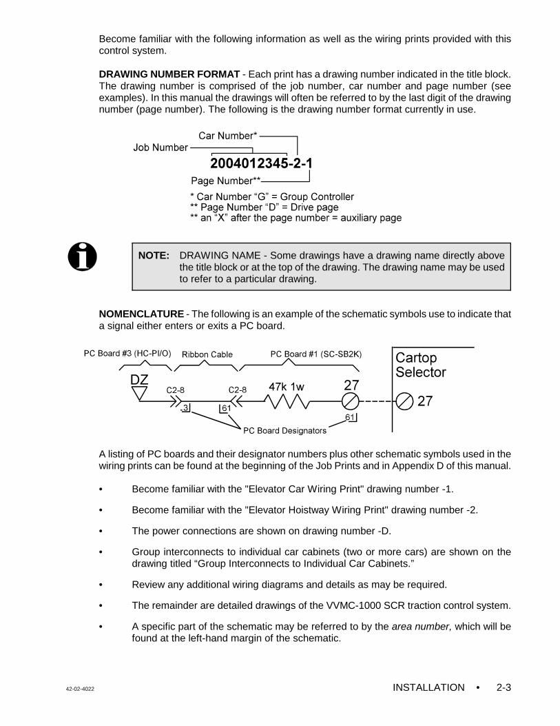
DRAWING NUMBER FORMAT - Each print has a drawing number indicated in the title block.The drawing number is comprised of the job number, car number and page number (seeexamples). In this manual the drawings will often be referred to by the last digit of the drawingnumber (page number). The following is the drawing number format currently in use.
NOMENCLATURE - The following is an example of the schematic symbols use to indicate thata signal either enters or exits a PC board.
A listing of PC boards and their designator numbers plus other schematic symbols used in thewiring prints can be found at the beginning of the Job Prints and in Appendix D of this manual.
• Become familiar with the "Elevator Car Wiring Print" drawing number -1.
• Become familiar with the "Elevator Hoistway Wiring Print" drawing number -2.
• The power connections are shown on drawing number -D.
• Group interconnects to individual car cabinets (two or more cars) are shown on thedrawing titled “Group Interconnects to Individual Car Cabinets.”
• Review any additional wiring diagrams and details as may be required.
• The remainder are detailed drawings of the VVMC-1000 SCR traction control system.
• A specific part of the schematic may be referred to by the area number, which will befound at the left-hand margin of the schematic.
• INSTALLATION 42-02-40222-4
NOTE: It is strongly recommended that you review the wiring guidelines in sections2.1.1 and 2.2 before bringing wires into the controller.
CAUTION: Do not allow any metal chips to fall into the electronics.
Keep the covers on the SCR Drive while wiring to prevent damage tothe components.
CAUTION: Power conductors from the fused disconnect, isolation transformer orother high voltage, high current conductors must be separated fromthe control wires. It is essential that the Encoder and Speed Sensorwires be placed in a separate conduit, away from high currentconductors.
NOTE: Pay very close attention to the hierarchy of the inspection inputs. In orderto maintain safe operation of the lift while on access, car top or in carinspection, the inspection circuits must be wired as shown in the prints.
2.1 CONTROLLER INSTALLATION
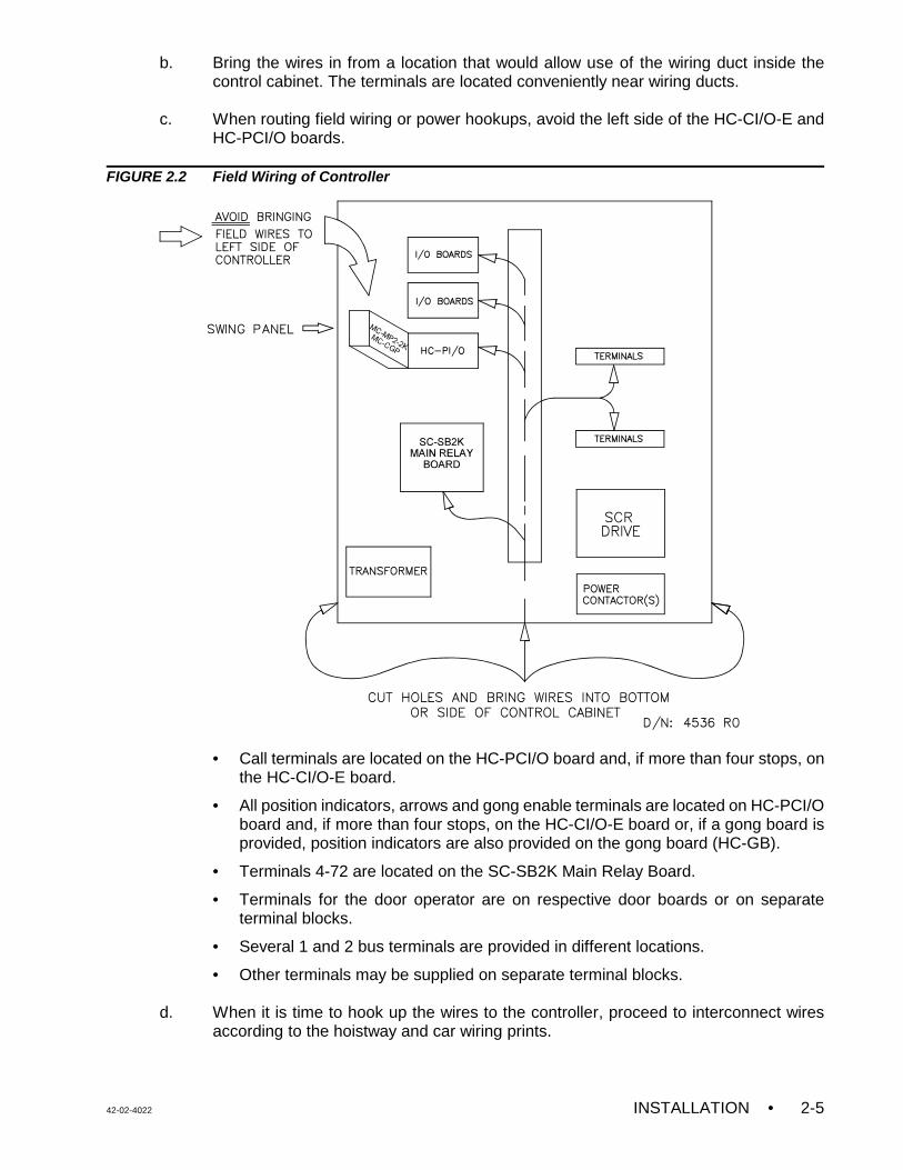
Mount the controller(s) securely to the machine room floor and cut holes to permit bringing thewires into the cabinet as shown in Figure 2.2. There may be labels in the cabinet to help identifylocations for wiring holes. Note that the standard MCE car control cabinet does not require rearaccess. Also, the doors are reversible and removable for ease of wiring.
2.1.1 CONTROLLER WIRING GUIDELINES
Figure 2.2 shows the recommended routing for the field wiring. Observe the following:
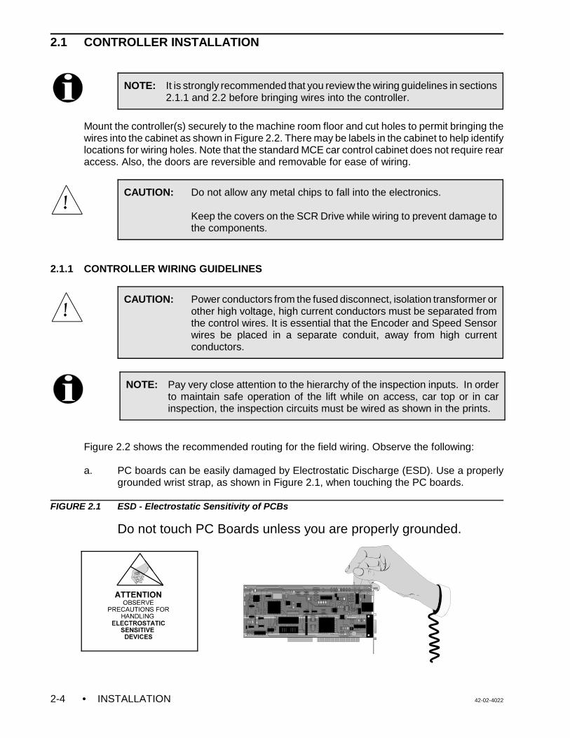
a. PC boards can be easily damaged by Electrostatic Discharge (ESD). Use a properlygrounded wrist strap, as shown in Figure 2.1, when touching the PC boards.
FIGURE 2.1 ESD - Electrostatic Sensitivity of PCBs
Do not touch PC Boards unless you are properly grounded.
42-02-4022 INSTALLATION • 2-5
b. Bring the wires in from a location that would allow use of the wiring duct inside thecontrol cabinet. The terminals are located conveniently near wiring ducts.
c. When routing field wiring or power hookups, avoid the left side of the HC-CI/O-E and
HC-PCI/O boards.
FIGURE 2.2 Field Wiring of Controller
• Call terminals are located on the HC-PCI/O board and, if more than four stops, onthe HC-CI/O-E board.
• All position indicators, arrows and gong enable terminals are located on HC-PCI/Oboard and, if more than four stops, on the HC-CI/O-E board or, if a gong board isprovided, position indicators are also provided on the gong board (HC-GB).
• Terminals 4-72 are located on the SC-SB2K Main Relay Board.
• Terminals for the door operator are on respective door boards or on separateterminal blocks.
• Several 1 and 2 bus terminals are provided in different locations.
• Other terminals may be supplied on separate terminal blocks.
d. When it is time to hook up the wires to the controller, proceed to interconnect wiresaccording to the hoistway and car wiring prints.
• INSTALLATION 42-02-40222-6
WARNING: Connecting the Group Supervisor directly to the building AC supplymay cause damage to PC boards. Also, connecting out-of-phasepower will cause damage. Check the “phasing” of the individual car2-bus lines before connecting them to the Group Supervisor. With avoltmeter set to AC Volts, measure between adjacent car 2-busterminals. The meter must read less than 10 VAC. If the reading ishigher, reverse the power leads going to the car's T1 transformer atL1 and L2, and measure again.
e. If the car controller is part of a group system, a separate conduit or wiring trough mustbe provided for the high-speed serial link between the car controller cabinet and theGroup Supervisor cabinet.
f. The main AC power supply wiring size must be determined by the electrical contractor.Proper motor branch circuit protection must be provided according to applicableelectrical code by using a fused disconnect switch or a circuit breaker for each elevator.Each disconnect or breaker must be clearly labeled with the elevator number.
g. If the car is part of a group system, there are a number of details relating to the wiringof the interconnects between the individual cars. They are as follows:
• If a group controller cabinet is provided, refer to the drawing titled “GroupSupervisor Field Wiring Print” in the job prints. Power for the M3 Group Supervisorcabinet comes from the local Car Controllers as shown in Controller drawing (-2).The main AC power supply wiring size must be determined by the electricalcontractor.
• A separate conduit or wiring trough must be provided for the high speed serial linkfrom each car controller to the Group Supervisor cabinet. The wiring details for thehigh speed communication link are fully detailed in the print titled “Instructions forConnection of High Speed Communication Cables”. Follow these instructionsexactly. Again, note the requirement for routing the high-speed interconnect cablesthrough a separate conduit or wiring trough.
• If applicable, also wire according to the drawing titled “Group Interconnects toIndividual Car Cabinets.” Make sure to ground all cabinets according to Section2.2.1.
• The field wiring to the Group Supervisor cabinet is found in the drawing titled “GroupSupervisor Field Wiring Print.”
2.2 GENERAL WIRING GUIDELINES
Basic wiring practices and grounding requirements are discussed in this section.
2.2.1 GROUND WIRING
To obtain proper grounding, quality wiring materials and methods should be used.
All grounding in the elevator system must conform to all applicable codes. Proper groundingis essential for system safety and helps to reduce noise-induced problems. The following aresome grounding guidelines:
42-02-4022 INSTALLATION • 2-7
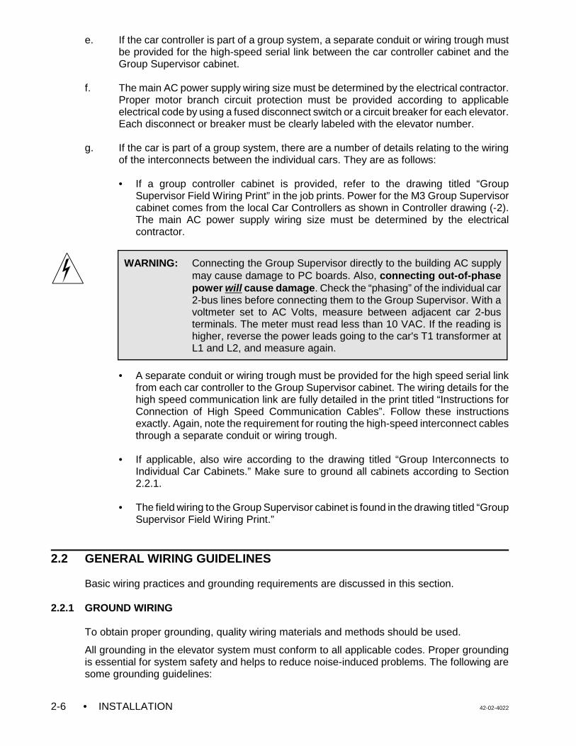
• The grounding wire to the equipment cabinet should be as large as, or larger than, theprimary AC power feeders for the controller and should be as short as possible.
• The grounding between equipment cabinets may be branching or a daisy chain, but thewire must terminate at the last controller and NOT loop back (see Figure 2.3).
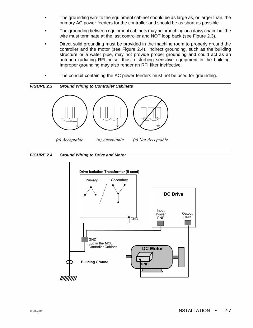
• Direct solid grounding must be provided in the machine room to properly ground thecontroller and the motor (see Figure 2.4). Indirect grounding, such as the buildingstructure or a water pipe, may not provide proper grounding and could act as anantenna radiating RFI noise, thus, disturbing sensitive equipment in the building.Improper grounding may also render an RFI filter ineffective.
• The conduit containing the AC power feeders must not be used for grounding.
FIGURE 2.3 Ground Wiring to Controller Cabinets
FIGURE 2.4 Ground Wiring to Drive and Motor
• INSTALLATION 42-02-40222-8
NOTE: Incoming power to the controller and outgoing power wires must be in theirrespective grounded conduit and must be separate from control wires bothinside and outside the control enclosure. The Encoder and speed sensorwiring must use a separate grounded conduit.
CAUTION: Do not drill any holes in the motor shaft to mount the magnet.This will weaken the shaft.
2.2.2 DC HOIST MOTOR, MOTOR FIELD AND BRAKE WIRING
a. If existing rotating equipment is being reused, it is strongly recommended to disconnectall of the wires from the terminals on the DC hoist motor armature, motor field andbrake. This is to guarantee that the controller is dis-connected from the rotatingequipment before the insulation test is performed.
Using a Megohmmeter, check for insulation breakdown between the frame of eachpiece of the motor and the armature, motor field and brake coil. A reading of 100Kohms or above is considered acceptable. Any insulation problems must be correctedbefore proceeding, as this may be an indication of a serious problem with theequipment.
b The hoist motor shunt field and brake wiring must use #14 AWG wire (or larger) ifcurrent level requires it.
c. The motor wiring must be brought to terminal A1M and A2M in the control cabinet. Fordetails of armature wiring, refer to drawing - D.
2.2.3 INSTALLING AND WIRING THE SPEED SENSOR
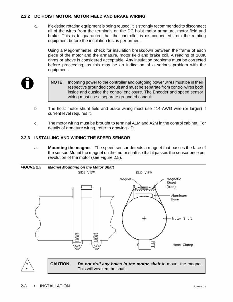
a. Mounting the magnet - The speed sensor detects a magnet that passes the face ofthe sensor. Mount the magnet on the motor shaft so that it passes the sensor once perrevolution of the motor (see Figure 2.5).
FIGURE 2.5 Magnet Mounting on the Motor Shaft
42-02-4022 INSTALLATION • 2-9
NOTE: The speed sensor must be electrically isolated from the motor body. MCEhas provided the required hardware to insulate the speed sensor from themotor body
CAUTION: Ensure that the speed sensor is perfectly perpendicular to andnot more than 1/8" (3.18 mm) away from the magnet.
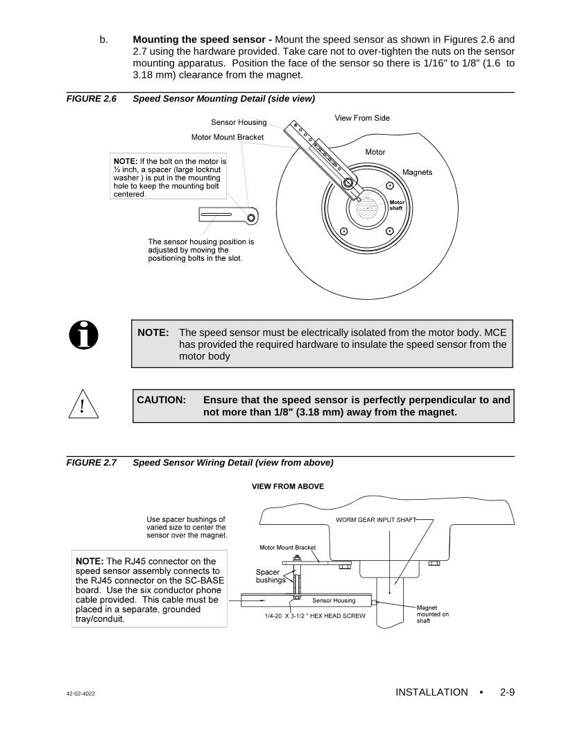
b. Mounting the speed sensor - Mount the speed sensor as shown in Figures 2.6 and2.7 using the hardware provided. Take care not to over-tighten the nuts on the sensormounting apparatus. Position the face of the sensor so there is 1/16" to 1/8" (1.6 to3.18 mm) clearance from the magnet.
FIGURE 2.6 Speed Sensor Mounting Detail (side view)
FIGURE 2.7 Speed Sensor Wiring Detail (view from above)
• INSTALLATION 42-02-40222-10
NOTE: All controllers have been set up with a BPS input that is fed directly by aBrake Contact or a Micro-switch. The purpose of this input is to monitor thebrake status and not for the purpose of energy saving. This is an additionalfeature. It may enhance the reliability of the system. It prevents theoperation of the elevator in the event that the brake fails to release in theintended manner. When this happens, the Brake Pick Failure message willscroll across the alphanumeric display.
NOTE: The Encoder wiring must use a separate grounded conduit. Make sure thatthe encoder housing is electrically isolated from the machine (ground). Tocheck this, place one ohmmeter lead on the frame of the machine and onelead on the case of the encoder. The speed sensor wires can be routedwith the encoder wires.
CAUTION: Do not coil excess Encoder cable near high voltage components asnoise may be induced. If necessary, shorten the cable at the Driveend. Do not cut and re-splice in the middle of the encoder cable orshorten at the Encoder end.
2.2.4 INSTALLING THE BRAKE SWITCH
A switch contact must be attached to the brake assembly if one does not already exist. This isneeded for the brake monitor circuit that shuts down the car in the event of a brake failure.There are many types of switches that can be used and there is no way to anticipate all themethods of mounting them. Take all necessary precautions to not interfere with the normalbrake design or operation. The contact must open when the brake is lifted and it should berated for at least 1/4 amp 125VAC. There are many micro-switches suitable for this application.
2.2.5 INSTALLING AND WIRING THE ENCODER
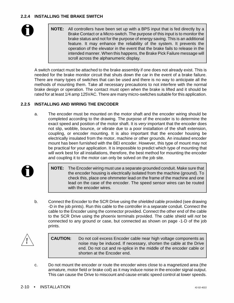
a. The encoder must be mounted on the motor shaft and the encoder wiring should becompleted according to the drawing. The purpose of the encoder is to determine theexact speed and position of the motor shaft. It is very important that the encoder doesnot slip, wobble, bounce, or vibrate due to a poor installation of the shaft extension,coupling, or encoder mounting. It is also important that the encoder housing beelectrically insulated from the motor, machine or other grounds. An insulated encodermount has been furnished with the BEI encoder. However, this type of mount may notbe practical for your application. It is impossible to predict which type of mounting thatwill work best for all installations, therefore, the best method for mounting the encoderand coupling it to the motor can only be solved on the job site.
b. Connect the Encoder to the SCR Drive using the shielded cable provided (see drawing-D in the job prints). Run this cable to the controller in a separate conduit. Connect thecable to the Encoder using the connector provided. Connect the other end of the cableto the SCR Drive using the phoenix terminals provided. The cable shield will not beconnected to any ground or case, but connected as shown on page -1-D of the jobprints.
c. Do not mount the encoder or route the encoder wires close to a magnetized area (thearmature, motor field or brake coil) as it may induce noise in the encoder signal output.This can cause the Drive to miscount and cause erratic speed control at lower speeds.
42-02-4022 INSTALLATION • 2-11
FIGURE 2.8 Typical Encoder Installations
2.3 HOISTWAY CONTROL EQUIPMENT INSTALLATION
This section covers the recommended procedures for installing the landing system, terminalslowdown switches, directional limit switches, hoistway access switches (if required), thehoistway access limit switch, and the emergency terminal slowdown switch.
2.3.1 INSTALLING THE LANDING SYSTEM - Refer to the installation drawings for the type oflanding system provided.
2.3.2 INSTALLING THE HOISTWAY LIMIT SWITCHES
a. The terminal landing slowdown switches should be installed and adjusted to openapproximately two inches beyond the point where a normal slowdown is initiated.
b. The direction limit switches should be installed and adjusted to open approximately oneinch beyond the terminal landing.
c. The emergency terminal slowdown switch (if required) should open approximately 50%of the slowdown distance from the terminal. This switch should be installed andadjusted to achieve the required operation according to the applicable elevator code.
d. Make sure that the cam that operates the slowdown and limit switches maintains theterminal slowdown switch open until the direction limit switch and emergency terminalslowdown switches (if required) are open.
e. Make sure that the terminal slowdown, direction limit and emergency terminal slowdownswitches are held open for the entire runby or overtravel of the elevator.
• INSTALLATION 42-02-40222-12
f. The hoistway access limit switch (if required) should be installed and adjusted to openand stop the elevator in the down direction when the top of the elevator is approximatelylevel with the top landing (when the top hoistway access switch is activated while onAccess or Inspection operation).
g. For faster geared elevators, the face of the cam operating the limit switches must besufficiently gradual so that the impact of the switch rollers striking the cam is relativelysilent.
2.3.3 INSTALLING THE LANDING SYSTEM CONTROL BOX (LS-QUTE-X-2K) - Refer to thedrawings in the job prints.
• The location for the landing system box should have already been selected.
• Holes are available on both sides and on the bottom of the landing system box formounting to any support brackets or structural channels. The mounting of the boxshould be very firm and solid so that knocking it out of alignment should be difficult. Use1/4-20 hardware.
• To install the tape into the tape guides on the LS-QUTE-X-2K landing system box,remove the 2 thumbscrews on the 2 guide assemblies, insert the tape and reinstall theguides with the thumbscrews (tighten firmly). If the installation has the LS-QUTE-X-2Kcar top selector with the additional sensor bracket on the rear of the tape, first removethe three 8-32 screws holding the protective 1" wide channel. This channel covers theback of the Door Zone sensors on the upper tape guide bracket. Remove the singlestandoff that is in the way of the thumbscrew holding the tape guide. Remove thethumbscrews holding the upper and lower tape guides, insert the tape, and reinstall theguides with the thumbscrews (tighten firmly). Reinstall the standoff (do not over-tighten)and the protective channel.
• After inserting the steel tape into the tape guides, check the location of the landingsystem box. The car should be at the top of the hoistway to make it easier to see if thealignment is causing any stress or binding on the tape guides. Make sure that the boxis vertical and plumb with the tape. This allows for easy tape movement and avoidsexcessive wear on the tape guides (using a level is helpful). Be careful so as to avoidpremature failure of the tape guides.
• Move the elevator to the top and bottom of the hoistway to check for smooth tapemovement and to make sure that there is no excessive pressure on the tape guides.Correct any problems immediately.
2.3.4 INSTALLING THE MAGNETIC STRIPS ON THE STEEL TAPE
a. Carefully, read and follow the Magnet Installation instructions in the job prints, but readthe rest of these instructions before proceeding.
b. Before installing the magnets, clean the steel tape thoroughly with an appropriatesolvent. No oil should be left on the tape as it will interfere with the adhesive backingon the magnets.
c. There are normally five lanes of magnets installed on the side of the tape facing the car.One lane consists of only the LU/DZ/LD and requires that a 6-inch magnet be installedat each floor. The other lanes have magnets which initiate slow downs.
42-02-4022 INSTALLATION • 2-13
d. If the installation has rear doors, it may have an LS-QUTE-X-2K landing system whichhas additional Door Zone sensors on the rear of the upper tape guide assembly. Followthe Magnet Installation instructions in the job prints and install the front and rear DoorZone magnets on the steel tape as shown.
2.3.5 DZX SWITCH
Depending on the type of landing system selector you have purchased we have installed asecond door zone sensor called DZX. For the LS-STAN-X system a second vane switch isinstalled in the center door zone lane. On the LS-QUTE system a third door zone sensor isplaced between the existing DZ sensors in the center lane. Since the DZX signal needs to berouted to the controller (SC-BASE board) you will need to connect DZX to your traveler.
2.3.6 TM SWITCH WIRING AND ADJUSTMENT (IF USED)
Refer to the drawing titled "Elevator Car Wiring Print" in the job prints for details on the wiringand setting of each contact in the TM switch. Carefully examine the functioning of this switch,especially if copper-to-carbon contacts are used. The current levels are quite low and may notbe enough to burn the oxide off the contacts.
2.3.7 DOOR OPERATOR DIODE INSTALLATION (IF USED)
Certain door operators, such as G.A.L. models MOM or MOH, require the installation of diodesin the door operator on the car top. See the drawing titled "Elevator Car Wiring Print" in the jobprints for any special instructions regarding these diodes.
2.3.8 DOOR POSITION MONITOR SWITCH (IF USED)
If you are in a jurisdiction where ASME A17.1 - 1996 or later is being enforced, Door PositionMonitor switch(s) connected to the DPM and/or DPMR inputs, must be added to monitor theposition of the closed doors. This must be a separate physical limit switch that makes upapproximately 1 to 2 inches before the doors lock.
42-02-4022 START-UP • 3-1
NOTE: A short to ground is defined as having a resistance of less than 20 ohmsbetween the 1-bus (common) and the terminal being checked.
NOTE: If existing rotating equipment is being reused, it is strongly recommendedto disconnect all of the wires from the terminals on the DC hoist motorarmature, motor field and brake. This is to guarantee that the controller isdis-connected from the rotating equipment before the insulation test isperformed.
Using a Megohmmeter, check for insulation breakdown between the frameof each piece of the motor and the armature, motor field and brake coil. Areading of 100K ohms or above is considered acceptable. Any insulationproblems must be corrected before proceeding, as this may be anindication of a serious problem with the equipment.
SECTION 3 START-UP
3.0 GENERAL INFORMATION
In this section, the car will be prepared for use by construction personnel so that they maycomplete the elevator installation. At this time the speed sensor must be properly installed asdescribed in Section 2.2.3. This section will cover the sequence of applying power to thecontroller and associated components, DC hoist motor and brake, and completing the initialadjustment of the system to get basic car movement on Inspection operation.
3.1 GROUND CHECK
Conduct a ground test before powering up the system. Refer to Figure 1.1 and Figures 2.3 and2.4 to help locate items as they are referred to in the ground check.
a. Remove fuse F4 in the individual car controller cabinet. If this is a group system, consultthe schematics and remove the fuse that powers terminal 2H (and 2F, if present).
b. Check for shorts to ground on all terminals on the bottom of the SC-SB2K Main Relayboard. The only terminals that should be grounded are terminals 1 and 89.
c. Check for shorts to ground on all terminals on the HC-PI/O and HC-CI/O-E boards.
d. Check for shorts to ground on terminals F1, F2, A1, A2, and D5. If a G.A.L. MOD dooroperator is provided, remove door fuses F7 and F8. For other door operators, consultthe prints as to which fuses to remove, then check the appropriate terminals for shortsto ground.
e. Check for shorts to ground on terminals L1P, L2P, L3P, A1M, A2M, MF1, MF2, B1 andB2.
• START-UP 42-02-40223-2
WARNING: These instructions assume the elevator mechanic has adequateelectrical troubleshooting experience. Follow the procedures carefullyand if the elevator does not respond correctly, check the circuits anduse the troubleshooting section in this manual (Section 6). Proceedcautiously. To become familiar with the procedure, read theseinstructions all the way through before starting the work.
3.2 BEFORE APPLYING POWER
In the following instructions it is assumed that the sling is suspended from the hoist ropes, allhoistway doors are closed (but not necessarily locked), and all hoistway and machine roomwiring is complete. The car safety must be adjusted to the manufacturer’s specifications andthe governor installed and roped. Test the safety by hand to make sure that it will hold the car.Correct any malfunction before proceeding further.
Before applying power to the controller, perform the following:
a. Physically check all of the power resistors and any other components located in theresistor enclosure and inside the controller. Any components loosened during shipmentmay cause damage.
b. Remove one side of the ribbon cable connecting the SC-SB2K board to the HC-PI/Oboard at connector C1 by pushing open the two latches.
c. Unplug the screw terminal blocks from the HC-PI/O and any HC-CI/O-E, HC-IOX orHC-I4O boards by moving the blocks to the right. This is done to avoid damaging theboards by accidentally shorting one of the output devices to one of the power buses(terminals 2, 3, or 4) during the initial power-up of the system.
MCE's VVMC-1000- SCR controller is designed to be able to operate on Inspection and Accesswithout the computers hooked up during start-up.
At this point, it is strongly recommended to read the manual for the SCR Drive Unit. The MCEinstallation manual contains information from the SCR drive manual, but has beensupplemented with additional information to clarify the installation and adjustment process.Therefore this manual should be used for installation and adjustments of the complete elevatorcontrol system. The original SCR Drive manual may be referenced, if necessary.
42-02-4022 START-UP • 3-3
WARNING: This equipment contains rotating parts on motors and machines andvoltages that may be as high as 600V. High voltage and moving partscan cause serious or fatal injury. Only qualified personnel familiarwith this manual and machinery should attempt to start-up or trouble-shoot this equipment. Observe these precautions:
a. USE EXTREME CAUTION: DO NOT TOUCH any circuit board,the SCR Drive, or a motor electrical connection without makingsure that the unit is properly grounded and that no high voltageis present. DO NOT apply AC power before grounding perinstructions herein.
b. Improper control operation may cause violent motion of the motorshaft and driven equipment. Be certain that unexpected motorshaft movement will not cause injury to personnel or damage toequipment. Peak torques of several times rated motor torque canoccur during a control failure.
c. Motor Armature and Field circuits may have high voltage presentwhenever AC power is applied, even when the motor is notrotating.
d. Make sure to use SHIELDED CABLE for the speed sensor, andwire it exactly as shown. Make sure to ground the controllercabinet according to local code.
CAUTION: Do not open the hinge cover or the drive top cover when the poweris ON. Turn OFF the main power before opening the drive covers.You may damage the top cover if it is not removed carefully . If topcover needs to be removed, first remove the small cover at thebottom front portion of the drive that covers logic terminals. Removethe two screws at the bottom front and gently pull (1/4th of an inchoutward) and then push the cover in the UP Direction.
3.3 APPLYING POWER - PREPARING TO MOVE THE CAR ON INSPECTION 3.3.1 INITIAL ADJUSTMENTS AND SAFETY CONSIDERATIONS
This control system uses an SCR drive to run the DC elevator motor. The SCR Drive suppliespower to the motor armature and the motor field to run the DC elevator motor. Simplifiedinstructions for getting the elevator moving are provided in this section. This assumes the SCRDrive has been set up at the factory to provide a satisfactory match to the motor characteristics.
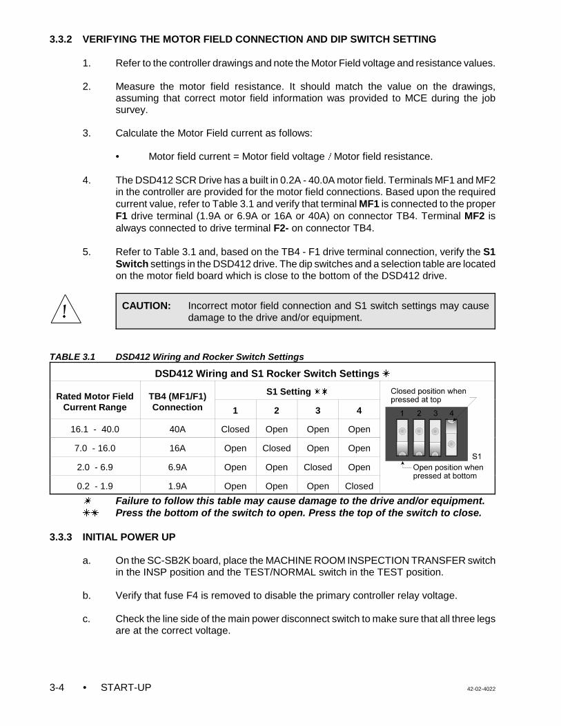
• START-UP 42-02-40223-4
CAUTION: Incorrect motor field connection and S1 switch settings may causedamage to the drive and/or equipment.
3.3.2 VERIFYING THE MOTOR FIELD CONNECTION AND DIP SWITCH SETTING
1. Refer to the controller drawings and note the Motor Field voltage and resistance values.
2. Measure the motor field resistance. It should match the value on the drawings,assuming that correct motor field information was provided to MCE during the jobsurvey.
3. Calculate the Motor Field current as follows:
• Motor field current = Motor field voltage ) Motor field resistance.
4. The DSD412 SCR Drive has a built in 0.2A - 40.0A motor field. Terminals MF1 and MF2in the controller are provided for the motor field connections. Based upon the requiredcurrent value, refer to Table 3.1 and verify that terminal MF1 is connected to the properF1 drive terminal (1.9A or 6.9A or 16A or 40A) on connector TB4. Terminal MF2 isalways connected to drive terminal F2- on connector TB4.
5. Refer to Table 3.1 and, based on the TB4 - F1 drive terminal connection, verify the S1Switch settings in the DSD412 drive. The dip switches and a selection table are locatedon the motor field board which is close to the bottom of the DSD412 drive.
TABLE 3.1 DSD412 Wiring and Rocker Switch Settings
DSD412 Wiring and S1 Rocker Switch Settings u
Rated Motor FieldCurrent Range
TB4 (MF1/F1)Connection
S1 Setting uu
1 2 3 4
16.1 - 40.0 40A Closed Open Open Open
7.0 - 16.0 16A Open Closed Open Open
2.0 - 6.9 6.9A Open Open Closed Open
0.2 - 1.9 1.9A Open Open Open Closed
u Failure to follow this table may cause damage to the drive and/or equipment.uu Press the bottom of the switch to open. Press the top of the switch to close.
3.3.3 INITIAL POWER UP
a. On the SC-SB2K board, place the MACHINE ROOM INSPECTION TRANSFER switchin the INSP position and the TEST/NORMAL switch in the TEST position.
b. Verify that fuse F4 is removed to disable the primary controller relay voltage.
c. Check the line side of the main power disconnect switch to make sure that all three legsare at the correct voltage.
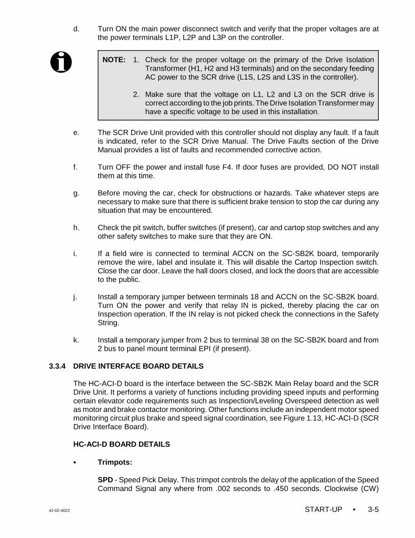
42-02-4022 START-UP • 3-5
NOTE: 1. Check for the proper voltage on the primary of the Drive IsolationTransformer (H1, H2 and H3 terminals) and on the secondary feedingAC power to the SCR drive (L1S, L2S and L3S in the controller).
2. Make sure that the voltage on L1, L2 and L3 on the SCR drive iscorrect according to the job prints. The Drive Isolation Transformer mayhave a specific voltage to be used in this installation.
d. Turn ON the main power disconnect switch and verify that the proper voltages are atthe power terminals L1P, L2P and L3P on the controller.
e. The SCR Drive Unit provided with this controller should not display any fault. If a faultis indicated, refer to the SCR Drive Manual. The Drive Faults section of the DriveManual provides a list of faults and recommended corrective action.
f. Turn OFF the power and install fuse F4. If door fuses are provided, DO NOT installthem at this time.
g. Before moving the car, check for obstructions or hazards. Take whatever steps arenecessary to make sure that there is sufficient brake tension to stop the car during anysituation that may be encountered.
h. Check the pit switch, buffer switches (if present), car and cartop stop switches and anyother safety switches to make sure that they are ON.
i. If a field wire is connected to terminal ACCN on the SC-SB2K board, temporarilyremove the wire, label and insulate it. This will disable the Cartop Inspection switch.Close the car door. Leave the hall doors closed, and lock the doors that are accessibleto the public.
j. Install a temporary jumper between terminals 18 and ACCN on the SC-SB2K board.Turn ON the power and verify that relay IN is picked, thereby placing the car onInspection operation. If the IN relay is not picked check the connections in the SafetyString.
k. Install a temporary jumper from 2 bus to terminal 38 on the SC-SB2K board and from2 bus to panel mount terminal EPI (if present).
3.3.4 DRIVE INTERFACE BOARD DETAILS
The HC-ACI-D board is the interface between the SC-SB2K Main Relay board and the SCRDrive Unit. It performs a variety of functions including providing speed inputs and performingcertain elevator code requirements such as Inspection/Leveling Overspeed detection as wellas motor and brake contactor monitoring. Other functions include an independent motor speedmonitoring circuit plus brake and speed signal coordination, see Figure 1.13, HC-ACI-D (SCRDrive Interface Board).
HC-ACI-D BOARD DETAILS
C Trimpots:
SPD - Speed Pick Delay. This trimpot controls the delay of the application of the SpeedCommand Signal any where from .002 seconds to .450 seconds. Clockwise (CW)
• START-UP 42-02-40223-6
rotation of the trimpot increases the time. This allows proper coordination of theacceleration of the car with the picking of the brake for minimum rollback and to preventacceleration before the brake picks.
BDD - Brake Drop Delay. Dropping the brake at the end of the run is delayed for a shorttime to allow the operation of the electric stop feature. This delay is adjustable from aminimum of 0.1 second fully CCW to 0.7 second fully CW.
ILO - Inspection Leveling Overspeed. The ILO trimpot on the HC-ACI board is not used.Set the ILO trimpot (on HC-ACI) fully CCW. On ASME A17.1 - 2000 compliantcontrollers, the ILO trimpot on the SC-BASE or SC-BASER board is used to set theInspection Leveling Overspeed threshold.
C Indicator:
ILO - Inspection Leveling Overspeed indicator. With the ILO trimpot set fully CCW thisindicator should never come
C Push Buttons:
FAULT RESET - If the ILO indicator is ON, this push button turns the fault indicatorOFF and drops out the FLT relay.
DRIVE RESET - This push button, provided for convenience, resets many SCR drivefaults. Drive faults are displayed on the drive keypad and can also be reset by pressingthe drive reset button on the drive keypad. Some faults, which cannot be reset in thismanner, require the power to be cycled OFF and then ON again.
HC-ACIF BOARD DETAILS - This board is only used for jobs with intermediate speeds.
C Trimpots:
ETS - Emergency Terminal Limit Speed adjust. The ETS trimpot on the HC-ACIF boardis not used. Set the ETS trimpot (on HC-ACIF) fully CW. On ASME A17.1-2000compliant controller, the ETS trimpot on the SC-BASE or SC-BASER board is used toset the Emergency Terminal limit Speed threshold.
C Indicators:
ETS FAULT - Emergency Terminal limit overspeed fault. With the ETS trimpot set fullyCCW this indicator should never come
AS FAULT - At Speed Fault indicator. This indicator will turn ON if the elevator’s speedexceeds the maximum or minimum limits set for contract speed.
DBF FAULT - Not applicable to the SCR drive.
C Push Buttons:
ETS RESET - This switch resets the Emergency Terminal Switch (ETS) Fault.
AS/DBF RESET - This switch resets the At Speed Fault.
42-02-4022 START-UP • 3-7
ADDITIONAL RELAYS AND DRIVE INTERFACE -External relays, HC-ACI-D & HC-ACIF areused for the drive interface. The following is an explanation of the key interface connectionsbetween the MCE controller and the DSD412 drive.
TB1-9 (Field Enable) - Activated to bring the motor field to forcing value.
TB1- 51 (Ramp rate select) - When active, selects the 2nd ACC/DCC rate.
TB1-8 (Run UP) - When active, selects the up direction.
TB1-50 (Run Down) - When active, selects the down direction.
TB1-7 (Loop contactor) - When active, confirms that the main contactor is ON.
TB1-49 (Reset) - When active, resets the drive faults.
TB1-11, 12, 53 (High speed) - All three inputs are activated to select the High speed.
TB1- 12, 53 (Intermediate speed) - These two inputs are activated to select the OneFloor speed.
TB1-12 (Level speed) - This input is activated to select the Level speed.
TB1- 54 (Inspection / Correction speed) - This input is activated to select Inspection/ Correction speed.
TB1- 41, 42 (Drive fault contacts) - Normally closed, opens if there is a fault.
TB1- 78 (Speed Deviation) - This output is normally ON. It turns OFF if the drivedetects an error between the commanded speed and the speed feedback.
TABLE 3.2 Speed Selection Table
Bit S0 Terminal 11
Bit S1Terminal 53
Bit S2Terminal 12
Bit S3Terminal 54
DriveParameter
Speed
1 1 1 0 156 - PresetSpeed #7
H Speed
0 1 1 0 155 - PresetSpeed #6
Intermediate Speed
0 0 1 0 153 - PresetSpeed #4
Level Speed
0 0 0 1 157 - PresetSpeed #8
Inspection/Correction Speed
0 0 0 0 0 Zero Speed
3.3.5 DRIVE PARAMETER SETTINGS
Each controller is shipped with completed parameter sheets. Appendix C has a form which canbe used to record changes and final parameter settings. All of the field adjustable parametershave been entered into the drive unit based upon the provided field information. However, itis essential to verify all the drive parameter settings before start up.
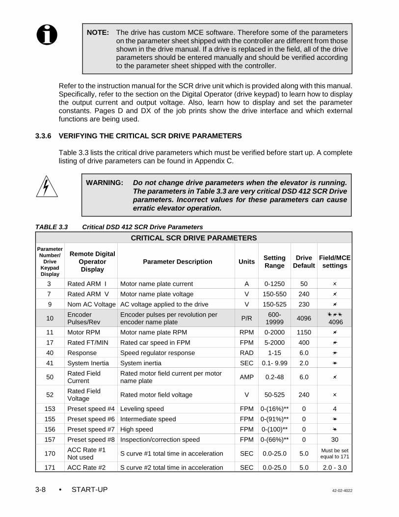
• START-UP 42-02-40223-8
NOTE: The drive has custom MCE software. Therefore some of the parameterson the parameter sheet shipped with the controller are different from thoseshown in the drive manual. If a drive is replaced in the field, all of the driveparameters should be entered manually and should be verified accordingto the parameter sheet shipped with the controller.
WARNING: Do not change drive parameters when the elevator is running.The parameters in Table 3.3 are very critical DSD 412 SCR Driveparameters. Incorrect values for these parameters can causeerratic elevator operation.
Refer to the instruction manual for the SCR drive unit which is provided along with this manual.Specifically, refer to the section on the Digital Operator (drive keypad) to learn how to displaythe output current and output voltage. Also, learn how to display and set the parameterconstants. Pages D and DX of the job prints show the drive interface and which externalfunctions are being used.
3.3.6 VERIFYING THE CRITICAL SCR DRIVE PARAMETERS
Table 3.3 lists the critical drive parameters which must be verified before start up. A completelisting of drive parameters can be found in Appendix C.
TABLE 3.3 Critical DSD 412 SCR Drive Parameters
CRITICAL SCR DRIVE PARAMETERSParameterNumber/
DriveKeypadDisplay
Remote DigitalOperatorDisplay
Parameter Description Units SettingRange
DriveDefault
Field/MCEsettings
3 Rated ARM I Motor name plate current A 0-1250 50 u
7 Rated ARM V Motor name plate voltage V 150-550 240 u
9 Nom AC Voltage AC voltage applied to the drive V 150-525 230 u
10 EncoderPulses/Rev
Encoder pulses per revolution perencoder name plate
P/R 600-19999
4096 uuu
4096
11 Motor RPM Motor name plate RPM RPM 0-2000 1150 u
17 Rated FT/MIN Rated car speed in FPM FPM 5-2000 400 u
40 Response Speed regulator response RAD 1-15 6.0 u
41 System Inertia System inertia SEC 0.1- 9.99 2.0 u
50 Rated FieldCurrent
Rated motor field current per motorname plate
AMP 0.2-48 6.0 u
52 Rated FieldVoltage
Rated motor field voltage V 50-525 240 u
153 Preset speed #4 Leveling speed FPM 0-(16%)** 0 4
155 Preset speed #6 Intermediate speed FPM 0-(91%)** 0 u
156 Preset speed #7 High speed FPM 0-(100)** 0 u
157 Preset speed #8 Inspection/correction speed FPM 0-(66%)** 0 30
170 ACC Rate #1Not used
S curve #1 total time in acceleration SEC 0.0-25.0 5.0 Must be setequal to 171
171 ACC Rate #2 S curve #2 total time in acceleration SEC 0.0-25.0 5.0 2.0 - 3.0
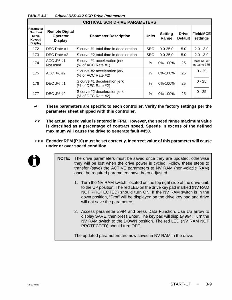
TABLE 3.3 Critical DSD 412 SCR Drive Parameters
CRITICAL SCR DRIVE PARAMETERSParameterNumber/
DriveKeypadDisplay
Remote DigitalOperatorDisplay
Parameter Description Units SettingRange
DriveDefault
Field/MCEsettings
42-02-4022 START-UP • 3-9
NOTE: The drive parameters must be saved once they are updated, otherwisethey will be lost when the drive power is cycled. Follow these steps totransfer (save) the ACTIVE parameters to NV RAM (non-volatile RAM)once the required parameters have been adjusted.
1. Turn the NV RAM switch, located on the top right side of the drive unit,to the UP position. The red LED on the drive key pad marked (NV RAMNOT PROTECTED) should turn ON. If the NV RAM switch is in thedown position, “Prot” will be displayed on the drive key pad and drivewill not save the parameters.
2. Access parameter #994 and press Data Function. Use Up arrow todisplay SAVE, then press Enter. The key pad will display 994. Turn theNV RAM switch to the DOWN position. The red LED (NV RAM NOTPROTECTED) should turn OFF.
The updated parameters are now saved in NV RAM in the drive.
172 DEC Rate #1 S curve #1 total time in deceleration SEC 0.0-25.0 5.0 2.0 - 3.0
173 DEC Rate #2 S curve #2 total time in deceleration SEC 0.0-25.0 5.0 2.0 - 3.0
174 ACC J% #1 Not used
S curve #1 acceleration jerk (% of ACC Rate #1)
% 0%-100% 25 Must be setequal to 175
175 ACC J% #2 S curve #2 acceleration jerk (% of ACC Rate #2)
% 0%-100% 25 0 - 25_______
176 DEC J% #1 S curve #1 deceleration jerk(% of DEC Rate #2)
% 0%-100% 25 0 - 25_______
177 DEC J% #2 S curve #2 deceleration jerk(% of DEC Rate #2)
% 0%-100% 25 0 - 25_______
u These parameters are specific to each controller. Verify the factory settings per theparameter sheet shipped with this controller.
uu The actual speed value is entered in FPM. However, the speed range maximum valueis described as a percentage of contract speed. Speeds in excess of the definedmaximum will cause the drive to generate fault #450.
uuu Encoder RPM (P10) must be set correctly. Incorrect value of this parameter will causeunder or over speed condition.
• START-UP 42-02-40223-10
WARNING: The motor circuit may have high voltage present whenever AC poweris applied to the controller, even when the motor is not rotating. Afterremoving the AC power, wait for a few minutes before opening thedrive cover. Use extreme caution. Do not touch any circuit board, powerdevice or electrical connection without ensuring that high voltage is notpresent.
3.4 MOVING THE CAR ON INSPECTION OPERATION
We must bypass the A17.1 - 2000 faults as these have yet to be adjusted. Place a jumperbetween the single pin terminals labeled 2KBP1 and 2KBP2 on the SC-BASE board. Also,invoke the software bypass by entering system mode. Once in system mode place the F6function switch in the UP position (ON) and set software option ABYP=ON (see section 5.3.2).Now we have two hours to run the car without worrying about nuisance shutdown due to theas yet unadjusted fault monitors. Once two hours have expired simply toggle the MACHINEROOM INSPECTION TRANSFER switch from NORM to INSP and back to NORM to get twomore hours of run time. Note that when the system is on inspection operation, with theswitches set as described above, there is no time limit to running the car with the bypassfunction invoked. Please exercise extreme caution when the fault monitors are bypassed.
Once all the steps described in the Sections 3.3.1, 3.3.2, 3.3.4 and 3.3.5 are accomplished,then proceed with the following.
a. Verify that the MACHINE ROOM INSPECTION TRANSFER switch on the SC-SB2Kboard is in the INSP position. Turn ON the main disconnect. There should not be anyfault message on the drive key pad display. If there is a drive fault message, refer to thefault section in the SCR drive manual. Upon power up, if the drive key pad displaysProt, place the NV RAM PROTECTION switch to the UP position, press the drive resetbutton. After the reset is accomplished place the NV RAM PROTECTION switch in theDOWN position. The red LED on the drive key pad marked (NV RAM NOTPROTECTED) should turn OFF.
NOTE: This installation is configured with an emergency brake (EB). The EB willapply when the car is away from door zone and both the doors are open.For access operation, move the lift to the desired location and then closeand lock the car gate. Relay CD should pick and this will keep theemergency brake from applying while the car is away from DZ. If the cargate is left open, the emergency brake will apply every time direction isdropped while on access operation. This will result in a slight delay, beforethe car is allowed to move, every time direction is picked.
NOTE: Before initial inspection run, verify the following trimpot settings:• COS trimpot on the SC-BASE or SC-BASER board fully CW• ETS trimpot on the SC-BASE or SC-BASER board fully CW• ILO trimpot on the SC-BASE or SC-BASER board fully CW• ILO trimpot on the HC-ACI board fully CCW• ETS trimpot on the HC-ACI board fully CW
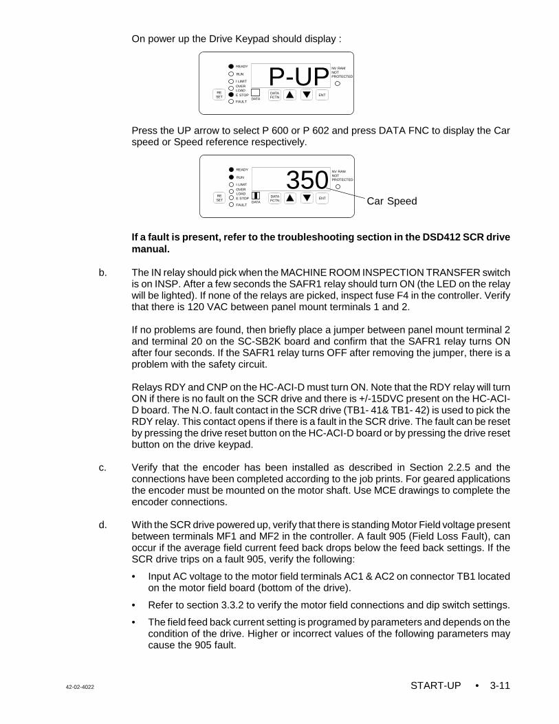
42-02-4022 START-UP • 3-11
RESET
DATAFCTN
ENT
READY
350NV RAMNOTPROTECTED
RUN
I LIMITOVERLOADE STOP
FAULTDATA Car Speed
RESET
DATAFCTN
ENT
READY
P-UPNV RAMNOTPROTECTED
RUN
I LIMITOVERLOADE STOP
FAULTDATA
On power up the Drive Keypad should display :
Press the UP arrow to select P 600 or P 602 and press DATA FNC to display the Carspeed or Speed reference respectively.
If a fault is present, refer to the troubleshooting section in the DSD412 SCR drivemanual.
b. The IN relay should pick when the MACHINE ROOM INSPECTION TRANSFER switchis on INSP. After a few seconds the SAFR1 relay should turn ON (the LED on the relaywill be lighted). If none of the relays are picked, inspect fuse F4 in the controller. Verifythat there is 120 VAC between panel mount terminals 1 and 2.
If no problems are found, then briefly place a jumper between panel mount terminal 2and terminal 20 on the SC-SB2K board and confirm that the SAFR1 relay turns ONafter four seconds. If the SAFR1 relay turns OFF after removing the jumper, there is aproblem with the safety circuit.
Relays RDY and CNP on the HC-ACI-D must turn ON. Note that the RDY relay will turnON if there is no fault on the SCR drive and there is +/-15DVC present on the HC-ACI-D board. The N.O. fault contact in the SCR drive (TB1- 41& TB1- 42) is used to pick theRDY relay. This contact opens if there is a fault in the SCR drive. The fault can be resetby pressing the drive reset button on the HC-ACI-D board or by pressing the drive resetbutton on the drive keypad.
c. Verify that the encoder has been installed as described in Section 2.2.5 and theconnections have been completed according to the job prints. For geared applicationsthe encoder must be mounted on the motor shaft. Use MCE drawings to complete theencoder connections.
d. With the SCR drive powered up, verify that there is standing Motor Field voltage presentbetween terminals MF1 and MF2 in the controller. A fault 905 (Field Loss Fault), canoccur if the average field current feed back drops below the feed back settings. If theSCR drive trips on a fault 905, verify the following:
• Input AC voltage to the motor field terminals AC1 & AC2 on connector TB1 locatedon the motor field board (bottom of the drive).
• Refer to section 3.3.2 to verify the motor field connections and dip switch settings.
• The field feed back current setting is programed by parameters and depends on thecondition of the drive. Higher or incorrect values of the following parameters maycause the 905 fault.
• START-UP 42-02-40223-12
Parameter 53 - Standing field current mode (may be the cause).Parameter 50 - Full field current mode (Accel/Decel) Parameter 49 - Field weakening mode (High speed)
e. Verify that the speed commands, acceleration, deceleration and S curves parametersare set correctly. Appendix C contains a complete listing of the DSD412 SCR DriveParameters. A completed parameter sheet with specific controller settings asprogrammed by MCE is shipped with each controller.
f. Connect a jumper wire between terminals 4 and 9 on the SC-SB2K board to overridethe gate switch and the door locks. If the car is on a final limit switch, place a jumperbetween panel mount terminals 2 and 16. This bypasses the main safety circuit.Remove these jumpers as soon as possible, for safety reasons.
g. Run the car by toggling the UP/DN toggle switch on the SC-SB2K board in the desireddirection using constant pressure. When the UP/DN switch is in the UP position, relayU (SC-SB2K) and UA (HC-ACI-D), UAX, UAXD should pick. When the UP/DN switchis in the DN position, relay D (SC-SB2K) and DA (HC-ACI-D), DAX, DAXD should pick.The speed reference (Parameter 602) on the drive key pad should display the correctInspection speed.
The M, BK and SAFR2 contactors should pick and the car should move. Make sure thatthe car moves in the appropriate direction and the brake works properly.
• If the car moves in the correct direction and speed, go to step ‘i’, Self Tune Test 1.
• If the car moves in the opposite direction, reverse the motor field connections.
• If the car does not move and the drive trips on Fault 98(Tach Loss Fault), verify theencoder connections.
• If the drive trips on Fault 99(Reverse Tach), the encoder connections are reversed.Switch A+ with B+ and A - with B -.
• If the car does not move on Inspection, refer to Section 6.5 for more details.
h. The Inspection Speed (Preset speed #8) is set by Parameter 157. Verify that Parameter602 displays the correct commanded speed and Parameter 600 displays the correct carspeed when the car moves on Inspection operation.
i. SELF TUNE TEST 1 (Parameter 997) - In the self tune test, the drive measures thetotal motor armature resistance, inductance, field L/R time. These values are used inconjunction with parameter #8 - Crossover Frequency to calculate the current andproportional gain of the speed regulator. Be sure to save the parameters and updatethe parameter sheet after completing the self tune.
1. Turn OFF the power. Remove fuses FB1 and FB2 and disconnect the brake coilwires connected to terminals B1 and B2 to prevent the brake from picking duringthis test.
2. Place a jumper across contact #3 (N.O.) of relay LPRM. This contact is in serieswith TB1-7 (loop contactor) circuit.
3. Place a jumper across contact #4 (N.O.) of relay MX.
4. Connect a jumper between terminal 2 and the right side of the MP1 coil or terminal2 and PM on the HC-ACI-D Board. This will allow the SCR drive to pick the M
42-02-4022 START-UP • 3-13
contactor during the self tune test. Disconnect and insulate the wire from the driveterminal TB1-9. This will prevent Fault 403 during Auto Tuning.
5. Verify that the car is on Inspection. Turn ON the power. If a Fault 405 (Safety CircuitFault) is displayed on the drive keypad it can be ignored.
6. On the SC-BASE board, install a jumper between pins 2KBYP1 and 2KBYP2. Also,enter System Mode, place the F6 function switch in the UP position (ON) and setsoftware option ABYP=ON (see section 5.3.2) to bypass ASME A17.1-2000 faults.
7. Refer to Section 3.8 in the SCR drive manual and carefully follow the instructionsto perform the SELF TUNE test (Function #997) or follow the steps describedbelow:
(a) Select Parameter 997. Press the DATA/FCTN key.
(b) If the drive keypad displays PROT, turn the Protection switch to the UPposition. This switch is located on the top right side of the drive cover. Thenpress the DATA/FCTN key.
(c) ENTER will be displayed. Press the ENTER key.
(d) The Drive will pick the M contactor and conduct the test. After the test iscompleted, PASS will be displayed on the drive keypad.
8. After completing Self Tune Test 1, record the values of the following:
• Parameter 613 - Measured Motor Field Resistance
• Parameter 614 - Measured Motor Inductance
• Parameter 615 - Measured Field L/R Time Constant
9. SELF Tune Test 2 ( Parameter 998) - This test verifies the SCR drive internaloperation and armature feedback circuits. Refer to Section 3.9 in the SCR drivemanual to perform the Power Unit Diagnostic (Function #998) or follow the stepsdescribed below:
(a) Select Parameter 998. Press the DATA/FCTN key.
(b) If the drive keypad displays PROT, turn the Protection switch to the UP position.This switch is located on the top right side of the drive cover. Then press theDATA/FCTN key.
(c) ENTER will be displayed. Press the ENTER key.
(d) The Drive will pick the M contactor and conduct the test. After the test iscompleted, PASS will be displayed on the drive keypad.
10. After completing Self Tune tests, MCE strongly recommends setting Parameter 2
= OFF. Then enter and SAVE the measured values of the following parameters. Thiswill force the drive to uses the measured values and avoid the possibility of selectingan incorrect value if parameter 2 = ON .
• Set parameter 4 = the measured value of parameter 613.
• Set parameter 6 = the measured value of parameter 614.
• Set parameter 51 = the measured value of parameter 615.
11. Save the drive parameters before turning OFF the power, otherwise the newvalues will be lost when power is cycled. Refer to the note in Section 3.3.6which explains how to save the parameters.
• START-UP 42-02-40223-14
NOTE: If an ILO (Inspection Leveling Overspeed) problem is detected by the HC-ACI-D board, the ILO indicator will turn ON and the FLT relay will pick,which will drop the RDY relay and shut down the controller. Reset the faultby pressing the Fault Reset button on the HC-ACI-D board and adjust theILO trimpot fully CCW.
12. Turn OFF the power. Install fuses FB1 and FB2 and re-connect the brake coil wiresto terminals B1 and B2. Remove the jumper between terminals 2 and PM or theright side of the MP1 coil. Reconnect the wire to terminal TB1-9. Remove thejumpers across contact #3 of relay LPRM and contact #4 of relay MX. Alsoremove the jumper between pins 2KBYP1 and 2KBYP2 on the SC-BASE board.Then turn ON the power and verify that software option ABYP=OFF (see section5.3.2)
j. Inspection Speed Calibration - Run the car on Inspection. Verify the Inspection speedusing a hand held Tachometer. Compare the measured car speed with Parameter 602(Reference speed) and then with Parameter 600 (car speed). These three valuesshould match if the car is running at the correct Inspection speed. Verify Parameter 10(Encoder P/R). If the actual speed is slower than the requested speed, increase theMotor RPM Parameter 11 (Motor RPM/SPD). If the actual speed is higher than therequested speed, decrease the value of Motor RPM Parameter 11. Parameter 11 canbe adjusted up to +/-5% of the motor rated F.L. RPM without having much effect on theperformance.
Now the correct Inspection speed (in feet per minute) should be displayed on the drivekeypad (Parameter 600) whenever the car moves on Inspection. Adjust the InspectionSpeed Parameter 157 (Preset Speed #8) for a comfortable Inspection speed. Thenadjust the SPD trimpot on the HC-ACI-D board to coordinate the application of thespeed command to the drive with the picking of the brake, so that the car does notmove under the brake or rollback at the start.
k. At this time the adjustment of the BDD trimpot on the HC-ACI-D board is alsonecessary. Otherwise you may be stopping the car under the brake, causing a lot ofcurrent to be applied to the motor that might cause arcing on the main contactor duringthe stop.
l. To make sure that the Cartop Inspection switch is working properly, turn OFF the maindisconnect, remove the jumper between terminals 18 and ACCN from step 3.3.3 (j), andreinstall the wire into terminal ACCN. Turn ON the main disconnect. Make sure thatthere is 115VAC on terminal ACCN with respect to terminal 1 when the CartopInspection switch is in the NORMAL position. There should be no power on terminalwhen the Cartop Inspection switch is in the INSP position.
NOTE: This installation is configured with an emergency brake (EB). The EBwill apply when the car is away from door zone and both the doors areopen. For access operation, move the lift to the desired location andthen close and lock the car gate. Relay CD should pick and this willkeep the emergency brake from applying while the car is away from DZ.If the car gate is left open, the emergency brake will apply every timedirection is dropped while on access operation.
42-02-4022 START-UP • 3-15
NOTE: If the car is not completely wired (temporary), check the following:• wire removed from panel mount terminal DCL• wire connected between panel mount terminal DPM and 2-bus• wire removed from terminal 47 on the SC-SB2K board• jumper from 2 bus to terminal 36 on the SC-SB2K board• jumper from 2 bus to terminal 38 on the SC-SB2K board• jumper from 2 bus to panel mount terminal EPI (if present)
NOTE: On modernizations it is easy to overlook the typical 40% counterweighting.Always put a 40% load in the car and check for equal motor current (upverses down) at Inspection speed in the middle of the hoistway. Equalcurrent readings on the keypad display indicate that the counterweight isclose to the correct value. Take whatever steps are necessary to achieveproper counterweighting. For a drum machine, follow the manufacturer’scounterweighting recommendation and test the drum machine’s limitswitches.
m. Stop the car so that the car top is accessible from the top hall door. Remove alljumpers from the safety circuit. Run the car from the car top. Verify that theSAFR1 relay drops out and the car stops when the Cartop Emergency StopSwitch is opened. Also, by opening the Emergency Stop Switch while the car ismoving up or down, verify that the brake stops and holds the car.
n. Run the car through the hoistway, checking clearance and the door locks. When all ofthe doors are closed, remove the jumpers from terminals 4 and 9, and fromterminals 18 and ACCN (if present). Correct any problem with the door locks.
o. Temporarily take the car off of Inspection operation. If the Diagnostic Indicators do notshow Test Mode, see what message is being displayed and correct the problem. Forexample, if the indicators show that the car is on Fire Service Phase 1, a jumper mustbe connected between terminal 2 on the back plate and terminal 38 on the SC-SB2Kboard in order to run the car on Normal operation. Remove the jumper once the FireService input is brought into the controller. Place the car back on Inspection.
p. Check the counterweight balance. Verify that the counterweighting is as specified. Makewhatever corrections are necessary to make the counterweight correct. If a drummachine is being used then follow the manufacturer’s recommendations for counterweighing, and test the limit switch on the drum machine.
q. Turn OFF the power. Reinstall the fuses that power terminals 2H and 2F. The elevatorcontroller installation should now be completed.
r. Remove the temporary jumper between 2 bus and terminal 38 on the SC-SB2K boardonce the Fire Service input is brought into the controller.
s. Remove the temporary jumper between 2 bus and panel mount terminal EPI (if present)once the Emergency Power input is brought into the controller.
42-02-4022 FINAL ADJUSTMENT • 4-1
NOTE: Pin 1 on both the ribbon cable connector and the header on the HC-PI/Oboard must match. These are designated with arrows on the connector andheader. Press the connector in until the latches snap, securing theconnector in place.
SECTION 4FINAL ADJUSTMENT
4.0 GENERAL INFORMATION
At this point, all the steps in Section 3 should have been completed. Please read Section 5before proceeding; it explains the adjustment and troubleshooting tools available with thecomputer. This section covers the final adjustment and testing procedures for controllers withthe MagneTek DSD 412 drive.
4.1 PREPARING TO RUN ON HIGH SPEED AND AUTOMATIC OPERATION
Move the car to the bottom landing on Inspection operation and disconnect all power. Reinsertconnector C1 into receptacle C1 on the HC-PI/O board (if previously removed).
4.1.1 DOOR OPERATOR
If the door operator is not working, turn OFF the power, pull the door fuses and close the doorsso the door clutch will not hit any of the door lock rollers. Take whatever steps are necessaryto keep the installation safe, but make sure that the cartop is still accessible after closing all ofthe doors.
4.1.2 HC-ACI-D AND HC-ACIF BOARD ADJUSTMENTS - In the process of preparing for runningthe elevator on high speed and automatic operation the following trimpots may requireadjustment.
C SPD trimpot (Speed Pick Delay) - This trimpot is located on HC-ACI-D board. It may needto be adjusted as described in Section 3 on Inspection operation to coordinate theapplication of the speed command with the picking of the brake. This trimpot may requirereadjustment when the car is adjusted for High speed in Section 4.3.5(g).
C BDD trimpot (Brake Drop Delay) - This trimpot is located on the HC-ACI-D board and it mayneed readjustment as described in Section 4.3.5(h). BDD controls the delay in dropping thebrake so that the brake drops just as car motion ceases.
C ILO trimpot (Inspection Leveling Overspeed) on the HC-ACI board - Not used on ASMEA17.1-2000 compliant controllers. Leave the ILO trimpot on the HC-ACI board fully CCW.Use the ILO trimpot on the SC-BASE or SC-BASER board to adjust the Inspection LevelingOverspeed threshold.
C ETS trimpot (Emergency Terminal Limit) on the HC-ACIF board - Not used on ASMEA17.1-2000 compliant controllers. Leave the ETS trimpot on the HC-ACIF board fullyCW. Use the ETS trimpot on the SC-BASE or SC-BASER board to adjust the EmergencyTerminal Limit Speed threshold.
• FINAL ADJUSTMENT 42-02-40224-2
4.1.3 DIAGNOSTIC MESSAGES AND INPUT/OUTPUT SIGNALS
To speed up final adjustment and troubleshooting, become familiar with the Status and ErrorMessages (Table 5.1) and Input/Output signals (Computer Flags, Tables 5.9 and 5.10).
ON-BOARD DIAGNOSTICS - Section 5 of this manual is dedicated to system diagnostics andan explanation of the human interface tools that are available with the Computer Swing Panel.These diagnostic tools simplify the adjustment and troubleshooting of the system. It isextremely important that Section 5 be read and understood before proceeding.
When the Diagnostics On/Norm switch is in the Norm position, the Diagnostic Indicatorsindicate when the system is ready for Normal operation. The Diagnostic Indicators must bescanning from right to left one light at a time. If the diagnostic lights are flashing any other way,an abnormal or special condition exists and the fault name will scroll on the alphanumericdisplay in English text. Tables 6.12 and 6.13 provide fault descriptions and troubleshooting tips.
The computer displays abnormal conditions in the same priority as they are evaluated. Forexample, if the safety string is open and the system is in Fire Service mode, the computer willshow that the safety string is open and will expect the mechanic to correct this problem firstsince it is a higher priority condition. Once the safety string has been made up and thecomputer recognizes this, then the computer will show that the car is on Fire Service mode.After successfully bringing in the Fire Service input, the computer will then start its normal scan.Once scanning normally, it is then possible to place calls and run the elevator automatically.
4.1.4 A FEW WORDS ABOUT ABSOLUTE FLOOR ENCODING
Absolute floor encoding (AFE) allows the controller to read encoding vanes or magnets at eachlanding and thereby identify the floor. Absolute floor encoding is provided as a standard.
If the car is not at a landing when power is turned ON, the controller will generate a downdirection command and the car will move toward the closest landing, provided that all abnormalconditions have been corrected. When the car reaches a landing and is within the Door Zone(relay DZ picked) with leveling completed (relays LU1, LU2, LD1 and LD2 not picked) thecontroller reads the floor code vanes or magnets and corrects the Position Indicator. If the caris on Automatic Operation, and if a home floor has been designated, the car will move to thehome landing at this time. If the car is at a landing, within the Door Zone (relay DZ picked) withleveling completed (relays LU1, LU2, LD1 and LD2 not picked) when AC power is turned ON,the controller will read the floor code vanes or magnets at the landing and correct the PositionIndicator. Again, if a home floor has been designated the car will move to this landing to park.
4.1.5 REGISTERING CAR CALLS
In the process of making final adjustments to the controller, periodically you will be asked toregister car calls. A call or series of calls can be registered at the controller by momentarilyplacing a jumper between terminal 1 (system common) and the desired car call terminal orterminals on the HC-PI/O or HC-CI/O-E board, and then between terminal 2 and terminal 45to allow the car to travel to each call. The car may move immediately after the first call isplaced, or it may wait several seconds before moving.
NOTE: To avoid conflicts between the A17.1 fault monitors and the nextseveral tests, place a jumper between 2KBP1 and 2KBP2 on SC-BASE. Enter system mode on swing panel and set ABYP = ON (SeeSection 5.3.2).
42-02-4022 FINAL ADJUSTMENT • 4-3
CAUTION: The call terminals on the HC-PI/O and HC-CI/O-E board should neverbe connected to any of the power terminals (such as 2, 3, 4, etc.). Ifthis happens and the call is turned on, it will blow the resistor-fuse ortriac which plugs into the board. Later versions of these boards mayhave plug-in zener diodes. These parts are designed to be field re-placeable and spares are provided in unused positions on the board,or are available from MCE. DO NOT JUMPER THESE PLUG-INCOMPONENTS AS IT MAY DESTROY THE BOARD OR OTHERCONTROLLER COMPONENTS. If any of these components shouldblow, FIND OUT WHY instead of constantly replacing them, as theconstant faults can eventually damage the board.
4.1.6 TEST MODE OPERATION
The purpose of TEST mode is to allow easy and convenient operation of the car so that thefinal adjustments can be made without cycling the doors. When the elevator is operated in theTEST mode, the elevator doors do not open. The door open relays are disconnectedautomatically during TEST mode operation.
The car is put into TEST mode by placing the TEST/NORMAL switch on the SC-SB2K (MainSafety Relay) board in the TEST position. Note that when the TEST/NORMAL switch is in theTEST position, it puts the car into Test Mode, provided that the Car Top Inspection and RelayPanel Inspection switches are in the OFF or normal positions. In that case, the DiagnosticIndicators should be showing TEST MODE. If the expected indication is not displayed, checkto see what message is being displayed and correct the problem. Operation while in TESTmode should be easy to understand by knowing the following:
a. Every time the car stops, a non-interference timer must elapse before the car can moveagain (the car will not move unless there is another car call). Note that after the timer haselapsed, the car will move immediately as soon as the next car call is placed (the car willnot move if the system is a single button collective system and there is no jumper fromterminal 2 to terminal 45). Placing a car call right after the car stops will require the non-interference timer to elapse before the car can move again.
b. Simply having one or more car calls registered will not necessarily cause the car to move.It will be necessary to jumper terminal 2 to terminal 45 to create a Door Close Button inputto get the car to move. If the car is not a single button collective but is a selective-collective,the jumper from terminal 2 to 45 will not be necessary. Leave a jumper connected fromterminal 1 to the last car call in the line of calls that have been placed. This will create aconstant pressure signal on the car call which is an alternate means of creating a DoorClose Button signal to get a car that is on Independent Service to leave the landing.However, the jumper from terminal 2 to terminal 45 may be more convenient.
c. If a jumper from terminal 1 is touched to the car call input for the floor where the car islocated, it will reestablish the non-interference timer and it must elapse before the car canmove again.
d. If the elevator is trying to level, it will not pick high speed and leave the landing until it hascompleted the leveling process. Drive Unit speed adjustments and direction limits atterminal landings may cause this problem.
• FINAL ADJUSTMENT 42-02-40224-4
NOTE: In order to access the parameter values, review Section 3, StandardControl / Display Unit Operation in the MagneTek DSD 412 SCR ElevatorDrive Technical Manual.
CAUTION: Verify the critical drive parameter settings as described in Section3.3.6. Incorrect values for these parameters can cause erraticelevator operation.
CAUTION: It is very important that drive parameters only be changed when the caris stopped and the elevator is on Inspection or Test operation.
e. If any of the inputs that open the door are active (Safety Edge On, Photo Eye On, Car Callinput grounded to 1 for the floor matching the Position Indicator, etc.) the car will not leavethe landing.
f. Both slowdown switch inputs (terminals 11 and 13) should never be inactive at the sametime when the doors are closed and locked and the safety circuit is closed.
4.2 EXPLANATION OF DSD 412 SCR DRIVE PARAMETERS AND S CURVES
Set ABYP = ON for two hours of run time with ASME A17.1-2000 functions bypassed whilesetting up drives. If necessary set ABYP to ON again for another two hours. See section 5.3.2for instructions on setting up ABYP=ON.Before attempting to bring the car up to contract speed, or making any adjustments, it isimportant to verify the following control parameters in the SCR Drive Unit. It is very importantto become familiar with drive keypad operation to access the drive program.
4.2.1 SETTING THE SPEED LEVELS
The VVMC Series M controller uses the Preset Speed Parameters described in Table 4.1. Thecontroller selects the desired speed using the DSD 412 SCR Drive Logic inputs as describedon page -DX in the Job Prints . The Speed Command Parameters should be set as shown inTable 4.1 in preparation for running the elevator at high speed.

42-02-4022 FINAL ADJUSTMENT • 4-5
Speed
TimeZero Speed
Leveling Speed
Intermediate Speed
High Speed
171 - ACC Rate #2172 - DEC Rate #1
175 - ACC J% #2
Contract Speed
1 to 5% of Contract Speed
Speed CommandParameters
S-CurveParameters
60 to 75% of Contract Speed
156 - Preset Speed #7
155 - Preset Speed #6
153 - Preset Speed #4
176 - DEC J% #1
171 - ACC Rate #2
175 - ACC J% #2
176 - DEC J%1
173 - DEC Rate #2
177 - DEC J% #2
175 - ACC J% #2
173 - DEC RATE #2
177 - DEC J% #2
TABLE 4.1 DSD 412 Speed Command Parameters
DSD 412 SPEED COMMAND PARAMETERS
Speed Parameter Number
Keypad Display Preferred setting in preparation for running thecar at High speed.
Unit
High 156 Preset Speed # 750% of Contract Speed (Parameter 17- RatedFPM). This parameter will be changed to ContractSpeed during final adjustment.
ft/m
Intermediate 155 Preset Speed # 642% of Contract Speed (Parameter 17- RatedFPM). This speed can be increased to 91% if required,but must be less than Contract Speed.
ft/m
Leveling 153 Preset Speed # 4 1% to 3 % of Contract Speed (Parameter 17- Rated FPM)
ft/m
Inspection/correction
157 Preset Speed # 8 Normal setting is 10% of the contract speed(Parameter 17 - Rated FPM).
ft/m
FIGURE 4.1 Velocity and S Curve Parameters (DSD 412)
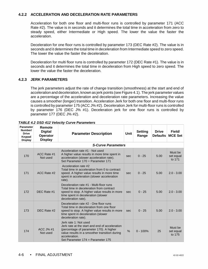
• FINAL ADJUSTMENT 42-02-40224-6
4.2.2 ACCELERATION AND DECELERATION RATE PARAMETERS
Acceleration for both one floor and multi-floor runs is controlled by parameter 171 (ACCRate #2). The value is in seconds and it determines the total time in acceleration from zero tosteady speed, either Intermediate or High speed. The lower the value the faster theacceleration.
Deceleration for one floor runs is controlled by parameter 173 (DEC Rate #2). The value is inseconds and it determines the total time in deceleration from Intermediate speed to zero speed.The lower the value the faster the deceleration.
Deceleration for multi floor runs is controlled by parameter 172 (DEC Rate #1). The value is inseconds and it determines the total time in deceleration from High speed to zero speed. Thelower the value the faster the deceleration.
4.2.3 JERK PARAMETERS
The jerk parameters adjust the rate of change transition (smoothness) at the start and end ofacceleration and deceleration, known as jerk points (see Figure 4.1). The jerk parameter valuesare a percentage of the acceleration and deceleration rate parameters. Increasing the valuecauses a smoother (longer) transition. Acceleration Jerk for both one floor and multi-floor runsis controlled by parameter 175 (ACC J% #2). Deceleration Jerk for multi-floor runs is controlledby parameter 176 (DEC J% #1). Deceleration jerk for one floor runs is controlled byparameter 177 (DEC J% #2).
TABLE 4.2 DSD 412 Velocity Curve ParametersParameterNumber/
DriveKeypadDisplay
RemoteDigital
OperatorDisplay
Parameter Description UnitSettingRange
DriveDefaults
Field/MCE Set
S-Curve Parameters
170 ACC Rate #1Not used
Acceleration rate #1 - Not usedA higher value results in more time spent inacceleration (slower acceleration rate). Set Parameter 170 = Parameter 171
sec 0 - 25 5.00Must beset equal
to 171
171 ACC Rate #2
Acceleration rate #2 Total time in acceleration from 0 to contractspeed. A higher value results in more timespent in acceleration (slower accelerationrate).
sec 0 - 25 5.00 2.0 - 3.00
172 DEC Rate #1
Deceleration rate #1 - Multi-floor runs Total time in deceleration from contractspeed to stop. A higher value results in moretime spent in deceleration (slowerdeceleration rate).
sec 0 - 25 5.00 2.0 - 3.00
173 DEC Rate #2
Deceleration rate #2 - One floor runsTotal time in deceleration from one floorspeed to stop. A higher value results in moretime spent in deceleration (slowerdeceleration rate).
sec 0 - 25 5.00 2.0 - 3.00
174 ACC J% #1Not used
Jerk rate 1: Not usedJerk rate at the start and end of acceleration(percentage of parameter 170). A highervalue results in a smoother transition duringacceleration. Set Parameter 174 = Parameter 175
% 0 - 100% 25Must beset equal
to 175
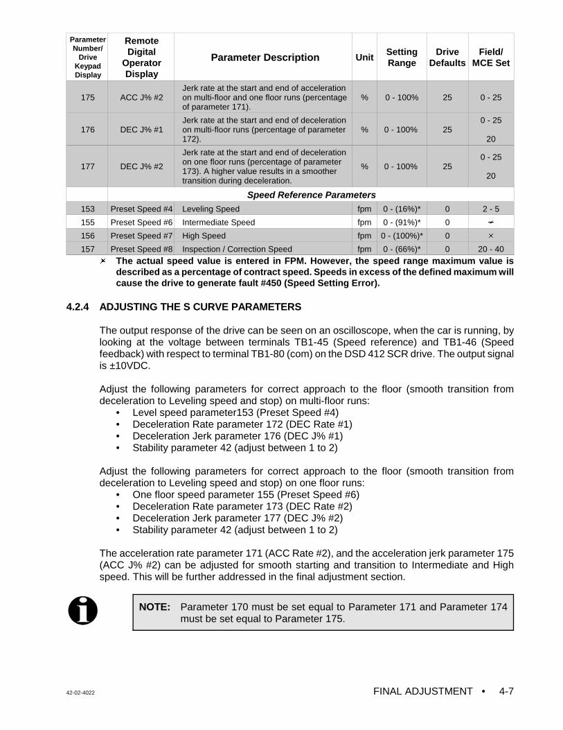
ParameterNumber/
DriveKeypadDisplay
RemoteDigital
OperatorDisplay
Parameter Description UnitSettingRange
DriveDefaults
Field/MCE Set
42-02-4022 FINAL ADJUSTMENT • 4-7
NOTE: Parameter 170 must be set equal to Parameter 171 and Parameter 174must be set equal to Parameter 175.
175 ACC J% #2Jerk rate at the start and end of accelerationon multi-floor and one floor runs (percentageof parameter 171).
% 0 - 100% 25 0 - 25
176 DEC J% #1Jerk rate at the start and end of decelerationon multi-floor runs (percentage of parameter172).
% 0 - 100% 250 - 25
20
177 DEC J% #2
Jerk rate at the start and end of decelerationon one floor runs (percentage of parameter173). A higher value results in a smoothertransition during deceleration.
% 0 - 100% 250 - 25
20
Speed Reference Parameters153 Preset Speed #4 Leveling Speed fpm 0 - (16%)* 0 2 - 5
155 Preset Speed #6 Intermediate Speed fpm 0 - (91%)* 0 u
156 Preset Speed #7 High Speed fpm 0 - (100%)* 0 u
157 Preset Speed #8 Inspection / Correction Speed fpm 0 - (66%)* 0 20 - 40
u The actual speed value is entered in FPM. However, the speed range maximum value isdescribed as a percentage of contract speed. Speeds in excess of the defined maximum willcause the drive to generate fault #450 (Speed Setting Error).
4.2.4 ADJUSTING THE S CURVE PARAMETERS
The output response of the drive can be seen on an oscilloscope, when the car is running, bylooking at the voltage between terminals TB1-45 (Speed reference) and TB1-46 (Speedfeedback) with respect to terminal TB1-80 (com) on the DSD 412 SCR drive. The output signalis ±10VDC.
Adjust the following parameters for correct approach to the floor (smooth transition fromdeceleration to Leveling speed and stop) on multi-floor runs:
• Level speed parameter153 (Preset Speed #4)• Deceleration Rate parameter 172 (DEC Rate #1)• Deceleration Jerk parameter 176 (DEC J% #1)• Stability parameter 42 (adjust between 1 to 2)
Adjust the following parameters for correct approach to the floor (smooth transition fromdeceleration to Leveling speed and stop) on one floor runs:
• One floor speed parameter 155 (Preset Speed #6)• Deceleration Rate parameter 173 (DEC Rate #2)• Deceleration Jerk parameter 177 (DEC J% #2)• Stability parameter 42 (adjust between 1 to 2)
The acceleration rate parameter 171 (ACC Rate #2), and the acceleration jerk parameter 175(ACC J% #2) can be adjusted for smooth starting and transition to Intermediate and Highspeed. This will be further addressed in the final adjustment section.
• FINAL ADJUSTMENT 42-02-40224-8
4.3 FINAL ADJUSTMENTS
4.3.1 FINAL PREPARATION FOR RUNNING ON AUTOMATIC OPERATION
a. Temporarily take the car off of Inspection operation. If the Diagnostic Indicators do notshow Test Mode, then see what message is being displayed and correct the problem.For example, if the indicators show that the car is on Fire Service Phase I, a jumpermust be connected between terminal 2 on the back plate and terminal 38 on the SC-SB2K board in order to run the car on Normal Operation. Remove the jumper once theFire Service input is brought into the controller. Place the car back on Inspection.
b. Move the car to the bottom terminal landing. Check to see if the DZ relay is picked. Ifnot, move the car on Inspection to place it in the Door Zone.
4.3.2 SWITCHING TO AUTOMATIC OPERATION
Place the Relay Panel MACHINE ROOM INSPECTION TRANSFER switch in the NORMposition. If the car is not at a landing it will move to a landing. If the car is at a landing but notin the door zone, relays L and either LU1/2 or LD1/2 should pick and the car should relevel. Ifthe relevel is not successful, check the following:
C If the brake picks and the car is trying to level but is not able to, it may be necessary toadjust the Level Speed parameter 153 (Preset Speed #4) on the SCR Drive to get thecar to move.
C If relays L and LD1/2 are picked, but the brake and other relays are not, the downdirection limit switch may be preventing the leveling down operation.
C If the car is trying to level, it will not leave the landing for a call until the leveling is
complete. Move the directional (normal) limit switch if necessary.
The Status Indicator lights should now display the indication for Independent Service operation.At this time the Position Indicator should match the actual car location. Note that all of thePosition Indicators and direction arrows are conveniently displayed on the controller. All thecalls are also displayed on the controller.
4.3.3 BRAKE ADJUSTMENT FOR 125% LOAD
a Put the car on Inspection at the bottom landing. Put 2/3 of a contract load in the car.
b. Begin adding weights in 50 or 100 pound increments and move the car up and downon Inspection each time. Adjust the brake tension to stop and hold 125% of contractload while running down on Inspection. KEEP THE CAR NEAR THE BOTTOM AS ITIS LIKELY TO SLIDE THROUGH THE BRAKE ONTO THE BUFFERS.
c. If the SCR Drive Unit trips off when the car is going down, but not while it is going up,refer to the manual for the SCR Drive Unit and look up the failure indicated on the Drivedisplay. If a fault is indicated, refer to the fault section. If this problem cannot be solved,call MCE Technical Support.
d. Remove all test weights from the car.
42-02-4022 FINAL ADJUSTMENT • 4-9
NOTE: It is very important that the drive parameters only be changed when the caris stopped and the elevator is on Inspection or Test operation so that thereis no demand.
NOTE: Drive gain adjustments - The default values for parameter 40(Response),parameter 41(Inertia) and the motor field adjustment are sufficient to runthe car on High Speed. However, for optimum performance, and to help inachieving Contract Speed, self tuning of the drive as described inSection 4.3.4 is strongly recommended.
4.3.4 SELF TUNING OF DSD 412 SCR DRIVE
If the self tuning described in Section 3.4.'i' has not been performed, perform the procedurenow. In the self tune test, the drive measures the total Motor armature resistance, inductanceand field L/R time constant. These values are used in conjunction with parameter #8 -Crossover Frequency, to calculate the current and proportional gain of the speed regulator.Refer to section 3.4 'i' to perform the self tuning procedure.
4.3.5 BRINGING THE CAR UP TO HIGH SPEED
a. Verify that all the steps described in Section 4.1 and Section 4.2 regarding theadjustments, specifically the drive parameters, are complete.
b. Register a car call one floor above the car. The High speed relay (H) should pick andthe drive display for parameter 600 (car speed) should read 50% of Contract Speed asthe car attempts to start. If the car runs normally, commence multi-floor runs and slowlyincrease the High Speed parameter 156 (Preset Speed #7) to the Contract Speedvalue. Once parameter 156 is set at contract speed the car should run at contractspeed. Verify contract speed using a hand held tachometer. The measured speedshould be equal to the displayed value of Parameter 600 and Parameter 602 when thecar runs at contract speed. If there is a problem reaching Contract Speed, see thefollowing note and also refer to section 4.3.4. Adjust parameter #49 (Weak Field Amps)to obtain the rated armature voltage at contract speed (see Section 4.3.6).
c. At the slowdown distance from the next floor, the Position Indicator will step. Afterstepping occurs, High speed drops and the car should rapidly decelerate to Levelingspeed.
The Leveling speed can be adjusted using parameter 153 (Preset Speed #4) so thatthe car levels into the floor and stops. Leveling speed should be 3 - 5 fpm, or usepersonal judgement in adjusting the leveling speed. If the car re-levels frequently,spread apart the LU and LD sensors or switches in the landing system to provideenough Dead Zone or lower the final leveling speed (Parameter 153).
d. Adjust the SPD (Speed Pick Delay) trimpot by first turning it far enough clockwise sothat the car rolls back in the direction of the load before accelerating. Then adjust SPDso that the brake is fully picked just as the motor first moves. SPD is used to avoidmoving the motor before the brake is fully lifted thus preventing rollback at the start ofcar motion.
e. Run the car again and verify that the car will start, accelerate, run at high speed,decelerate and run at Leveling speed into the floor and stop. Place calls for all of the
• FINAL ADJUSTMENT 42-02-40224-10
NOTE: To observe the commanded speed and the drive output with anoscilloscope or a chart recorder, monitor drive terminal TB1-45 and TB1-46with respect to TB1-80. Take all necessary precautions while measuringthe voltage signals.
CAUTION: Most oscilloscopes have a grounding pin on their power plug. Werecommend defeating the grounding pin with one of the commonlyavailable ground isolation adapter plugs so that the case of theoscilloscope is not at ground potential, but at the potential of the leadto which the negative probe is connected. TREAT THE CASE OFTHE OSCILLOSCOPE AS A LETHAL SHOCK HAZARD,DEPENDING ON WHERE THE NEGATIVE PROBE ISCONNECTED. This recommendation is being made because theground potential on the grounding pin of the power outlet may not bethe same as the controller cabinet ground. If it is not, substantialground loop current may flow between the negative probe and thepower plug grounding pin which can ruin the oscilloscope
landings. Verify that all of the calls work. Verify the operation and placement of all vanesor magnets and vane or magnet switches and verify that the car steps the PositionIndicators correctly. The slowdown distance for the elevator is measured from the pointwhere the STU sensor (or STD sensor, if going down) is activated by a metal vane ormagnetic strip, to the position where the car is stopped at the floor with the DZ sensorcentered on the leveling target with LU or LD sensors not engaged.
This slowdown distance was chosen to give a reasonable deceleration rate. Continueto make two-floor runs. If the car is not running at contract speed, slowly increase Highspeed parameter 156 (Preset Speed #7) until Contract Speed is reached. It may benecessary to adjust the deceleration rate parameter 172 (DEC Rate #2) anddeceleration jerk parameter 176 (DEC J% #2) to get the car to approach the floorcorrectly as the car speed increases. Adjust the acceleration rate parameter 171 (ACCRate #2) and acceleration jerk parameter 175 (ACC J% #2) until the desiredacceleration is achieved. Several runs may be required to obtain optimum acceleration.The acceleration rate should be about the same as the deceleration rate.
If the job does not have Intermediate speed, set P177 = P176 and P173 = P172. If thejob has Intermediate speed, go to step 'f'.
f. Intermediate Speed - If the job has Intermediate speed, first make the adjustments formulti-floor runs. Then make one floor runs and adjust the Intermediate Speedparameter 155 (Preset Speed #6) to reach the correct Intermediate speed. There mayalso be a need to adjust parameter 173 (DEC Rate #2) for the correct approach to thefloor (refer to Figure 4.1 Velocity and S Curve Parameters described in Section 4.2.4).
If, after these adjustments, the car still takes a longer time in the approach to the flooron an Intermediate speed run, there is a possibility that the Intermediate Steppingvanes/magnets (ISTU/ISTD) are installed too far away from the floor. To verify this,reduce the ISTU/ISTD) distance for a middle floor (away from the terminal landings).Then adjust parameters 155 and 173 for the correct approach. If this is successful,implement the change in the ISTU/ISTD distances for the other floors. Note: Parameter177 should be set between zero and three (0 - 3).
42-02-4022 FINAL ADJUSTMENT • 4-11
g. Speed Pick Delay - To achieve a proper start, without rollback or snapping away fromthe floor, a variable delay before applying the speed signal has been provided (trimpotSPD, Speed Pick Delay). This was adjusted previously; however, check trimpot SPDagain and make adjustments if necessary. Do this with an empty car. SPD must beadjusted to let the brake just clear the brake drum before attempting to accelerate thecar. The correct setting will be obvious by watching the drive sheave. The response ofthe car can also be monitored using an oscilloscope by measuring the voltage on thedrive terminals TB1- 45 (Speed reference) and TB1-46 (Speed feedback) with respectto terminal TB1-80 (com) on the DSD 412 SCR drive. The output signal is 0, +/-10VDC.
h. Brake Drop Delay - When the elevator slows to leveling speed and enters the deadzone, the speed command drops to zero and the SCR Drive Unit causes the machineto stop electrically. The dropping of the brake must be delayed long enough to allow thesheave to stop turning before setting the brake firmly on the brake drum. This isadjusted using the BDD (Brake Drop Delay) trimpot. The idea is to hold the brake uplong enough to allow the motor to be stopped electrically and then drop the brake theinstant the motor has stopped.
If there is too much delay before dropping the brake, the SCR Drive will release controlof the motor and the motor will drift briefly in the direction of the load before the brakeis forced to drop by the PT relay. The BDD trimpot controls the dropping of the brakethrough the BE relay.
Move the LU and LD sensors or switches closer together (or further apart) so the carstops at the same location, up or down. Then move the floor (leveling) magnet stripsor vanes so the car stops accurately at each floor.
I. The acceleration rate parameter setting should be at least as great as the decelerationrate parameter, but should not substantially exceed the value of the deceleration rateparameter. Excessive acceleration may cause the SCR Drive circuits to saturate andthereby lose control of the car. Ideally, the slope of the acceleration in volts per secondshould be equal to the slope of the deceleration.
Note the present value of the deceleration rate parameter 172 (DEC Rate #1). Continueto increase the value of parameter 172 until the car overshoots the floor on multi-floorruns, requiring a relevel operation. Observe the response of the car to verify a stablereleveling operation. Return the parameter 172 value ( DEC Rate #1) to its originalvalue so that the approach to the floor is the same as before.
After the car stops, check the empty car releveling operation by placing a jumperbetween terminals 18 and 26 to cause an up level after which the car will stop due topicking the LD (Down Level) switch. Remove the jumper from terminals 18 and 26 andthe car will level down against the counterweight. Make sure that it does not stall. If thecar stalls, increase the leveling speed.
4.3.6 MOTOR FIELD AND ARMATURE VOLTAGE ADJUSTMENTS
The armature voltage is a result of the motor field current times the rotational speed. The goalis to have the armature voltage be equal to the name plate voltage while running at the nameplate RPM and full load current. The following information is required to adjust the motor fieldcorrectly:
• Motor name plate Armature Voltage.• Motor Field Voltage.• Motor Field resistance.
Motor Field current = Motor Field Voltage / Motor Field Resistance.
• FINAL ADJUSTMENT 42-02-40224-12
The DSD412 SCR drive motor field voltage is adjusted by adjusting the motor field currentvalues using the following drive parameters:
• 50 - Full Field Current (sets the forcing field current)• 49 - Running Field Current (sets the weakening/running field voltage)• 52 - Rated Motor Field Voltage• 53 - Standing Field Current (sets the standing field Voltage)
Motor terminal voltage = CEMF + I x RCEMF = Counter EMF I x R = Voltage drop in the motor armature;
I = Parameter 3 (Armature current) R = Parameter 4 (Armature resistance)
Note: Self tuning of the DSD412 drive as described in Section 4.3.4 should be complete.
Step 1: Calculate the CEMF voltage.CEMF voltage = Motor name plate voltage - [Armature current P#3 x Armatureresistance P#4]
Step 2: Select parameter 609 and press the Data FNCT Key . This parameter displays theCEMF voltage.
Step 3: Run the car at contract speed in both directions and the read the CEMF voltagedisplayed by parameter 609. If the value of CEMF is equal to the above calculatedvalue then the adjustments are complete. At this time motor armature voltagedisplayed in parameter 610 should be equal to the motor name plate voltage. Thedisplayed value will be equal to the motor name plate in the overhauling direction anda higher value in the motoring direction.
Step 4: If the displayed value of CEMF in parameter 609 is lower than the calculated valuein step 1, increase the running motor field current (parameter 49) in small incrementsuntil the value of CEMF equals the calculated value in both directions. If the displayedvalue of CEMF in parameter 609 is higher than the calculated value in step 1,decrease the running motor field current (parameter 49) in small increments until thevalue of CEMF equals the calculated value in both directions.
4.3.7 SPEED CALIBRATION
At this time the motor should be running with correct armature voltage. If required, adjust therunning motor field as described in step 4.3.6. Verify contract speed using the hand heldtachometer. The measured value of speed should be equal to the displayed value of parameter600 and parameter 602 when the car runs at contract speed. If the measured value is lowerthan the displayed values, increase parameter 11 (Motor RPM/SPD). If the measured value ishigher than the displayed value, decrease the value of parameter 11. Parameter 11 can beadjusted to +/- 5% of the motor rated RPM without having much effect on the performance.
4.3.8 LOAD TESTING
a. Begin adding test weights to the car in 100 or 200 pound increments all the way up tothe rated load. Observe the SCR Drive current (Parameter 611) on the display andcheck to see if there is a Fault 918 (IST Fault) as the car accelerates to full speed. If so,this indicates that the SCR unit is being pushed close to its limits and may require oneor more of the following actions:
42-02-4022 FINAL ADJUSTMENT • 4-13
WARNING: The following tests should be performed only by qualified elevatorpersonnel skilled in final adjustment and inspections.
1. The requested acceleration rate may be excessive. Reduce the accelerationrate by increasing parameter 171 (ACC Rate #2). Increasing this parameter willlower the rate of acceleration, and reduce the current demand.
2. A more gradual transition from acceleration to high speed may be made byincreasing parameter 175 (ACC J% #2) between zero and three (0 - 3).
3. The motor may be underrated. It may be possible to get excellent results if theacceleration is reduced slightly.
4. The elevator may be improperly counter weighted. This possibility should bethoroughly investigated by placing a balanced load in the car and verifying thatthe armature current is the same in both the up and down directions.
5. Make a copy of the table in Appendix C, Quick Reference for MagneTekDSD412 SCR Drive Parameters and use the digital operator on the drive unitto look up and write down every parameter value as programmed in the unit.Have this data in hand BEFORE calling MCE.
b. If there is a problem lifting the fully loaded car, adjust parameters 40 (Response) and41 (System Inertia). If there is a problem slowing the car in the down direction, adjustthe deceleration rate parameter 172 (DEC Rate #1).
4.4 FINAL ELEVATOR INSPECTION PROCEDURE
4.4.1 INSPECTION LEVELING OVER SPEED TEST
Note: Before performing tests 4.4.1 and 4.4.3, please remove the jumper between pins labeled2KBP1 and 2KBP2 on the SC-BASE board. Also rotate trimpots ILO, ETS and COS fully CW.
The SC-BASE board is equipped with an independent low speed monitoring system which canshut down the system if the car runs faster than a trimpot adjustable preset speed on Car TopInspection, Hoistway Access or Leveling operation. The monitoring system is active when theLeveling (LU1/LU2, LD1/LD2) relays are picked or when the Access/Inspection relay (IN1) isdropped out. The trimpot is labeled ILO (Inspection Leveling Overspeed) and is located on theSC-BASE board. The circuit looks at pulses coming from the speed sensor, sensing a magneton the motor shaft or brake drum, etc. Calibrate this circuit as follows:
a. An accurate representation of actual car speed is required for this test. If the calibrationin Section 3.4 'j' was performed, then parameter 600 - Car Speed may be used.Otherwise a hand-held tachometer is required.
b. Place the car on Inspection operation by placing the MACHINE ROOM INSPECTIONTRANSFER switch in the INSP position on the SC-SB2K.
• FINAL ADJUSTMENT 42-02-40224-14
c. Set the Inspection speed to 140 fpm (or the maximum Inspection speed available if lessthan 140 fpm) using the Inspection speed parameter 157 (Preset Speed #8). Run thecar and verify the speed using either parameter 600 or a hand-held tachometer.
d. Move the car to a lower floor. Run the car in the up direction on Inspection while veryslowly turning the ILO trimpot CCW until the ILO1/ILO2 indicators just turn ON, trippingthe ILO Fault. The car should come to an immediate stop. The ILO fault will self resetin a moment.
e. Set the Inspection speed parameter 157 (Preset Speed #8) to a lower value. Then runthe car again on Inspection, increasing the speed in increments of 2 fpm usingParameter 157. Verify that the low speed safety monitor circuit will trip the ILO Fault atno higher than 140 fpm (or no higher than the maximum available inspection speed ifless than 140 fpm). Check this in both directions.
f. Set the Inspection speed Parameter 157 (Preset Speed #8) back to the original ordesired value. Place the MACHINE ROOM INSPECTION TRANSFER switch on theSC-SB2K board in the NORM position.
4.4.2 TERMINAL SLOWDOWN LIMIT SWITCHES
Make sure that the terminal slowdown limit switches are working properly by performing thefollowing steps:
a. Place the TEST/NORMAL switch, on the SC-SB2K board in the TEST position.
b. Disconnect and label the wires at terminals 71 (STU) and 72 (STD) on the SC-SB2Kboard.
c. Register calls for the terminal landings (top and bottom). The car should make a normalslowdown at both terminal landings, except that there may be a slight relevel (which isokay). If the car goes more than an inch past the floor, move the slowdown limit untilthe approach is normal.
d. Reconnect the wires to terminals 71 (STU) and 72 (STD) on the SC-SB2K board andreturn the TEST/NORMAL switch to the NORMAL position.
4.4.3 EMERGENCY TERMINAL LIMIT SWITCH MONITOR
All jobs under the requirements of ANSI A17.1-2000 Articles 2.25.4.1. or 2.25.4.2 must havea means to insure that the car speed is below contract speed after opening the associated ETSlimit switches. The emergency terminal limit switch monitor performs this function.
The SC-BASE board carries out ETS monitoring functions via a speed senor that monitors amagnet installed on the motor shaft or brake drum as described in Section 2.2.3, Installing andWiring the Speed Sensor.
a. Make sure that shielded phone cable from the sensor to the SC-BASE board is securelyseated in the connectors at both ends and is also enclosed in conduit.
b. On the SC-BASE board, verify that the ETS trimpot is fully CW.
42-02-4022 FINAL ADJUSTMENT • 4-15
NOTE: The car should be at the bottom landing with the TEST/ NORM switch onthe SC-SB2K board in the TEST position.
c. Record the value of the High Speed parameter 156 (Preset Speed #7). Then, on amulti-floor run, adjust the speed of the car to 95% of contract speed by adjusting theHigh speed parameter 156 (Preset Speed #7).
d. Remove the wire from the Up Emergency Terminal Limit Switch where it connects tothe controller at terminal UETS1 and UETS2 on the SC-BASE board. Start the car atthe bottom of the hoist way and while running the car in the up direction, slowly turn theETS trimpot CCW until the ETS1/ETS2 indicators turn ON and the car stops. An “ETSFault” message should be displayed on the MC-MP2-2K alphanumeric display.
e. Press the fault reset push button on the SC-SB2K board to reset the fault.
f. Repeat (d) and (e) in the down direction with the wire from the DETS terminal removed.When the calibration is complete, reconnect the wires removed from the UETS andDETS terminals and return the High Speed parameter 156 (Preset Speed #7) to itsoriginal value.
g. Verify the calibration by turning OFF the inspection transfer switch. Place a call, andwith the car running at contract speed, remove the field wires from the UETS1 andUETS2 terminals on the SC-BASE board. The car must execute an emergencyslowdown. To restore normal operation, replace the wires and press the Fault Resetpushbutton on the SC-SB2K board. Repeat for terminals DETS1 and DETS2.
4.4.4 CONTRACT SPEED BUFFER TEST:
4.4.4.1. COUNTER WEIGHT BUFFER TEST WITH EMPTY CAR GOING UP
To conduct the empty car buffer test going UP, a number of functions need to be bypassedusing jumpers. Follow the steps below:
a. On the SC-SB2K board, install the jumper between pins 2KBP1 and 2KBP2. Also entersystem mode and then select option ABYP = ON (See section 5.3.2).
b. On the SC-BASE board, place the PFLT Bypass jumper in the ON position to bypassthe PLD ILO, ETS and contract overspeed fault functions.
c. Disconnect the Step Up (STU) input by removing the wire from terminal 72 on the SC-SB2K board. Tape the wire to prevent shorting.
d. Bypass the Emergency Terminal Up Limits, if provided, by placing jumpers betweenterminals 2 and UETS1 / UETS2 on the SC-BASE board.
e. Bypass the Up terminal slowdown and Up Normal Limit by placing jumpersbetween terminals 9 and 10 and terminals 10 and 11 on the SC-SB2K board.
f. Register a car call for the top terminal landing from the controller. The counter weightwill strike the buffer.
g. Put the elevator on Inspection and pick the down direction to move the car.
• FINAL ADJUSTMENT 42-02-40224-16
h. Remove the jumpers between terminals 9 and 10, and terminals 10 and 11 andreconnect the wire to terminal 72 on the SC-SB2K board.
i. On the SC-BASE board, place the PFLT Bypass jumper in the OFF position to enablethe PLD ILO, ETS and contract overspeed fault functions.
j. On the SC-SB2K board, remove the jumper between pins 2KBP1 and 2KBP2. Alsoenter system mode and then select option ABYP = OFF.
4.4.4.2 CAR BUFFER TEST WITH A FULL LOAD GOING DOWN
a. On the SC-SB2K board, install the jumper between pins 2KBP1 and 2KBP2. Also entersystem mode and then select option ABYP = ON (See section 5.3.2).
b. On the SC-BASE board, place the PFLT Bypass jumper in the ON position to bypassthe PLD ILO, ETS and contract overspeed fault functions.
c. Disconnect the Step Down (STD) input by removing the wire from terminal 71 on theSC-SB2K board. Tape the wire to prevent shorting.
d. Bypass the Emergency Terminal Down Limits, if provided, by placing jumpersbetween terminals 2 and DETS1 / DETS2 on the SC-BASE board.
e. Bypass the Down terminal slowdown and Down Normal Limit by placing jumpersbetween terminals 9 and 12 and terminals 12 and 13 on the SC-SB2K board.
f. Position the elevator several floors above the bottom landing with a full load in the car.Then register a car call for the bottom landing. The car will strike the buffer.
g. Put the elevator on Inspection and pick the up direction to move the car.
h. On the SC-BASE board, place the PFLT Bypass jumper in the OFF position to enablethe PLD ILO, ETS and contract overspeed fault functions.
i. Remove the jumpers between terminals 9 and 12 and terminals 12 and 13 andreconnect the wire to terminal 71 on the SC-SB2K board. Remove all of the jumpersinstalled in this section.
j. On the SC-SB2K board, remove the jumper between pins 2KBP1 and 2KBP2. Alsoenter system mode and then select option ABYP = OFF.
4.4.5 GOVERNOR AND CAR SAFETY TESTS
4.4.5.1 GOVERNOR ELECTRICAL OVERSPEED SWITCH TEST - Make sure that there areno jumpers between terminals 2 and 15. Trip open the electrical OVERSPEED switch contactmanually and verify that the main safety circuit drops out. Use which ever method is mostfamiliar to verify the actual electrical and mechanical tripping speeds.
4.4.5.2 GOVERNOR AND CAR SAFETY OVERSPEED TEST WITH FULL LOAD GOINGDOWN.
a. Move the fully loaded car to the top terminal landing and turn power OFF.
42-02-4022 FINAL ADJUSTMENT • 4-17
NOTE: The following is required only if a drive fault is generated when the test isperformed in step ‘k’.
Note the values of parameters 49 (Weak Field Amps), 50 (Full Field Amps) and57 (Field Weaken Speed). Then set the parameters as follows:• 49 = 50% of its present value• 50 = 50% of its present value• 57 = 60% of its present value• Verify that parameter 56 (Field Strength Speed) = 90%.
b. On the SC-BASE board, place the PFLT BYP jumper in the ON position to bypass thePLD ILO, ETS and contract overspeed fault functions.
c. If the HC-ACIF board is used in this controller, remove relays AS and ETL from their
sockets. Keep them separate! ETL is 48 VDC and AS is 12 VDC.
d. Connect a jumper between terminals EBS1 and EBS2 to bypass the governoroverspeed switch.
e. In order to observe the loss of traction (when the safety mechanism sets) connect ajumper between terminal 16 on the SC-SB2K board and panel mount terminal 17 tobypass the safety plank (SOS) switch.
f. Turn the power ON and verify that the controller is functional.
g. On the SC-BASE board, install the jumper between pins 2KBP1 and 2KBP2. Also, entersystem mode and set option ABYP = ON to activate the ASME A17.1 - 2000 bypassfunction (see Section 5.3.2).
h. Set the SCR drive parameter 81 (Overspeed Mult) = 1.40 or to the required trippingspeed. If the trip point is greater than 150%, skip steps (h), (i) (j) und (k) and use othermeans to overspeed the car.
i. Enable the overspeed test by setting parameter 80 (Overspeed Test) = ON. Thissetting changes back to OFF immediately after the test run. It is necessary to repeatthis step if another test run is required.
j. Set parameter 12 = 150.
k. Register a car call in the down direction, but not for the bottom landing. The car shouldexceed Contract Speed. The governor should trip and set the safety and stop the car.
l. Put the car on Inspection.
m. Reset the SCR drive parameters: 81 (Overspeed Mult) = 1.0, 12 (Over Speed %) =110 and verify that parameter 80 (Overspeed Test) = OFF.
n. If any of the following parameters were changed, return them to their original values:49 (Field Weakening Amps, 50 (Full Field Amps), 57 (Field Weaken Speed) and 56(Field Strength Speed).

• FINAL ADJUSTMENT 42-02-40224-18
o. Reset the mechanical governor and inspect the hoist ropes to make sure they are in theproper grooves.
p. Move the car UP on Inspection to release the flexible guide clamp safety or release thecar safety by hand if it is a wedge clamp type.
q. Remove the jumper between terminals EBS1 and EBS2 which bypasses thegovernor overspeed switch.
r. Remove the jumper from PC board terminal 16 and panel mount terminal 17which bypasses the safety plank (SOS) switch).
s. Properly reinstall relays AS and ETL on HC-ACIF board (if used). These relays wereremoved or partially removed from their respective sockets. Remember AS and ETL aredifferent!
t. Remove the jumper between pins 2KBP1 and 2KBP2 on the SC-BASE board. Also,enter System Mode and set ABYP = OFF (see Section 5.3.2).
u. On the SC-BASE board, place the PFLT BYP jumper in the OFF position to enable thePLD ILO, ETS and contract overspeed fault functions.
v. Put the car on Normal operation by taking the car off Inspection. After the elevator findsa floor, verify the operation of the elevator by registering calls and checking the speed.
4.4.6 MOTOR FIELD LOSS DETECTION TESTS
Put the car on Inspection. Turn OFF the controller power and disconnect the motor field wiresat terminals MF1 and MF2. Turn ON the power. The SCR drive will detect the motor field failurefault. Place a call and observe that car does not run. Turn OFF the power and reconnect thewires at terminals MF1 and MF2.
The drive adjustments and tests are complete. Now complete the A17.1 Code CompliantFunctions and Testing (Section 4.5) and then fine tune any areas that may require touching up.Make sure that all of the appropriate data has been properly documented and that all ofthe jumpers have been removed before the car is returned to service.
4.5 A17.1 - 2000 CODE COMPLIANT FUNCTIONS AND TESTING
This section of the manual outlines the calibration and testing of the portion of the controlsystem used to meet the requirements of the ASME A17.1 -2000 code. First, verify that theoverspeed functions for ETS and ILO have been calibrated as described in 4.4.
After completing the overspeed test, test both the ascending car overspeed and unintended carmovement protection.
4.5.1 OVERSPEED CALIBRATION AND TESTING
Please refer to section 4.4 for calibration of the ILO and ETS overspeed detection logic.
On the SC-SB2K board move the MACHINE ROOM INSPECTION TRANSFER switch to theINSP position and place the TEST/ NORMAL switch in the TEST position.

42-02-4022 FINAL ADJUSTMENT • 4-19
4.5.2 ASCENDING CAR OVERSPEED PROTECTION
Prior to this test the governor overspeed switch velocity setting needs to be checked bywhatever means is normally used. The emergency brake must be installed and adjusted permanufacturer’s specifications. Note that it is especially critical for the “Rope Brake” style ofemergency brake, that the brake shoes are properly “arced-in” to conform with the curvatureof the ropes.
a. Refer to Section 5.3.2 ASME A17.1 - 2000 BYPASS FUNCTION and follow theinstructions under For bypass for 2 hours in Automatic Operation to:
1. On the SC-BASE board, place a jumper between 2KBP1 and 2KBP2.
2. On the SC-SB2K board, place the TEST/NORM switch on TEST.
3. Set the auto bypass function ABYP = ON.
b. Run empty car to bottom landing and have a technician monitor car speed with a handoperated tachometer. With doors closed, use what ever method you are familiar withto overspeed the car in the up direction. As the car accelerates have the technician callout car speed so that the car can be stopped if the governor overspeed switch does notactivate when required.
c. Once the governor overspeed switch opens the Emergency Brake should immediatelyapply and bring the car to a rapid stop.
d. To restore normal operation, reset GOV overspeed switch, press and hold theEmergency Brake Reset pushbutton on the SC-BASE board. Remove all jumpers, setthe auto bypass function ABYP = OFF and place the F6 down (OFF). Turn OFFinspection and place TEST/NORMAL on NORMAL.
4.5.3 UNINTENDED CAR MOVEMENT PROTECTION
a. For safety, station a mechanic at the landing where the test is to be performed.
b. Bring the car to the mechanic and arrange to open both the car and hoistway doors.Place barricades in front of the open car and hoistway doors.
c. Meanwhile, back in the machine room, use whatever method you are familiar with toallow the car to drift away from the landing with doors open.
d. As the car moves away from the floor, observe that the emergency brake stops andholds the car within 48" of floor level.
e. To restore normal operation, close and lock both the car and hoistway doors and thenpress and hold the Emergency Brake Reset pushbutton (SC-BASE board) until theemergency brake resets.
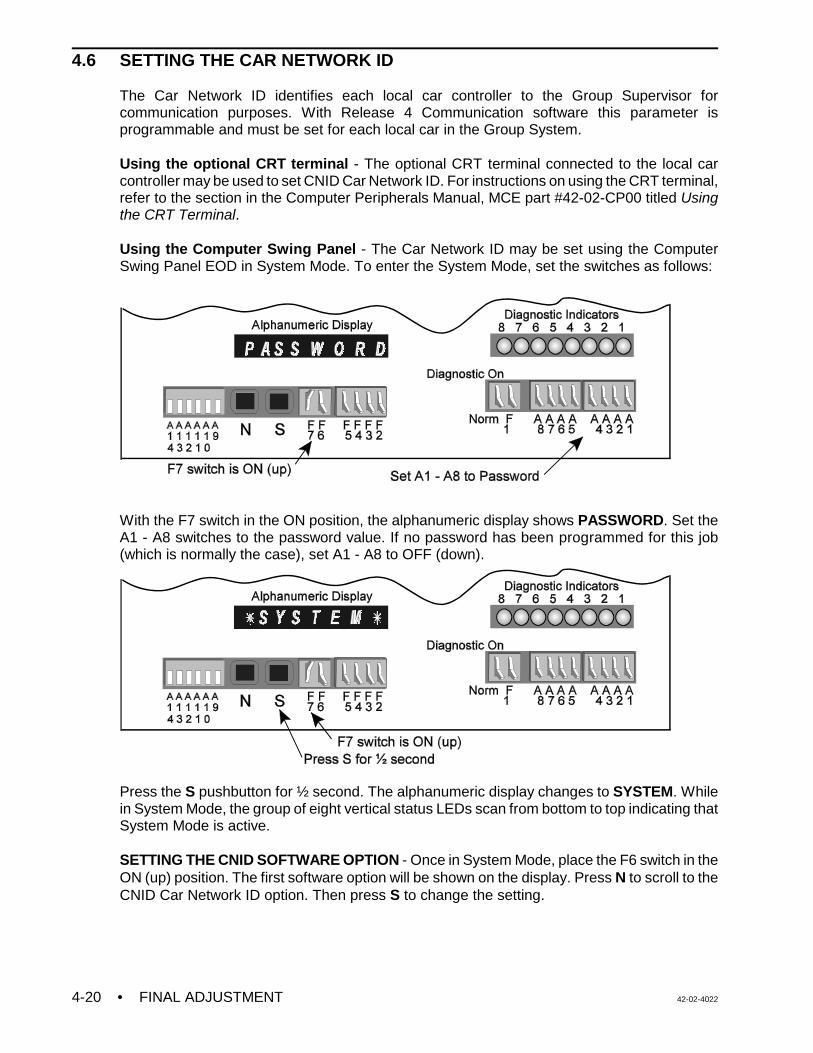
• FINAL ADJUSTMENT 42-02-40224-20
4.6 SETTING THE CAR NETWORK ID
The Car Network ID identifies each local car controller to the Group Supervisor forcommunication purposes. With Release 4 Communication software this parameter isprogrammable and must be set for each local car in the Group System.
Using the optional CRT terminal - The optional CRT terminal connected to the local carcontroller may be used to set CNID Car Network ID. For instructions on using the CRT terminal,refer to the section in the Computer Peripherals Manual, MCE part #42-02-CP00 titled Usingthe CRT Terminal.
Using the Computer Swing Panel - The Car Network ID may be set using the ComputerSwing Panel EOD in System Mode. To enter the System Mode, set the switches as follows:
With the F7 switch in the ON position, the alphanumeric display shows PASSWORD. Set theA1 - A8 switches to the password value. If no password has been programmed for this job(which is normally the case), set A1 - A8 to OFF (down).
Press the S pushbutton for ½ second. The alphanumeric display changes to SYSTEM. Whilein System Mode, the group of eight vertical status LEDs scan from bottom to top indicating thatSystem Mode is active.
SETTING THE CNID SOFTWARE OPTION - Once in System Mode, place the F6 switch in theON (up) position. The first software option will be shown on the display. Press N to scroll to theCNID Car Network ID option. Then press S to change the setting.
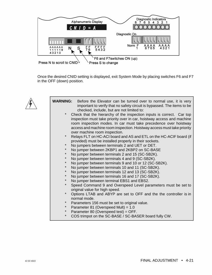
42-02-4022 FINAL ADJUSTMENT • 4-21
WARNING: Before the Elevator can be turned over to normal use, it is veryimportant to verify that no safety circuit is bypassed. The items to bechecked, include, but are not limited to:
* Check that the hierarchy of the inspection inputs is correct. Car topinspection must take priority over in car, hoistway access and machineroom inspection modes. In car must take precedence over hoistwayaccess and machine room inspection. Hoistway access must take priorityover machine room inspection.
* Relays FLT on HC-ACI board and AS and ETL on the HC-ACIF board (ifprovided) must be installed properly in their sockets.
* No jumpers between terminals 2 and UET or DET.* No jumper between 2KBP1 and 2KBP2 on SC-BASE* No jumper between terminals 2 and 15 (SC-SB2K).* No jumper between terminals 4 and 9 (SC-SB2K).* No jumper between terminals 9 and 10 or 12 (SC-SB2K).* No jumper between terminals 10 and 11 (SC-SB2K).* No jumper between terminals 12 and 13 (SC-SB2K).* No jumper between terminals 16 and 17 (SC-SB2K).* No jumper between terminal EBS1 and EBS2.* Speed Command 9 and Overspeed Level parameters must be set to
original value for high speed.* Options LTAB and ABYP are set to OFF and the the controller is in
normal mode.* Parameters 156 must be set to original value.* Parameter 81 (Overspeed Mult) = 1.0* Parameter 80 (Overspeed test) = OFF.* COS trimpot on the SC-BASE / SC-BASER board fully CW.
Once the desired CNID setting is displayed, exit System Mode by placing switches F6 and F7in the OFF (down) position.
42-02-4022 ONBOARD DIAGNOSTICS • 5-1
SECTION 5 ONBOARD DIAGNOSTICS
5.0 GENERAL INFORMATION
The VVMC-1000 Series “M” traction controller includes user-friendly diagnostic tools that helpthe mechanic install and service the equipment. The diagnostic tools available on the controllerinclude an optional CRT terminal and the Enhanced Onboard Diagnostics (EOD). The CRTterminal provides the elevator mechanic with a set of easy-to-use menus for the purpose ofservicing and troubleshooting the controller. More information about the CRT is available fromthe MCE Computer Peripherals manual. This section covers the Computer Swing Panel'sEnhanced On-Board Diagnostics.
5.1 ENHANCED ONBOARD DIAGNOSTICS (EOD) OVERVIEW
The Computer Swing Panel provides the Enhanced Onboard Diagnostics (EOD). A quick lookat the switches and LEDs provides an overview of the elevator and its functions. Once familiarwith the equipment, an elevator mechanic can understand the current operating conditions ofthe elevator and diagnose a problem using the EOD. No external devices are required to viewthe status of the elevator and see what the elevator control system is actually trying to do. TheEnhanced Onboard Diagnostics operate in three modes, Normal, System and Diagnostic. Allthree modes are discussed in detail in this section.
5.1.1 DESCRIPTION OF EOD LIGHTS AND SWITCHES
The following is a description of the EOD indicators and switches (see Figure 5.1)
COMPUTER ON LED - The Computer ON LED, when it is ON continuously, indicates that theMC-MP2-2K Main Processor board is functioning normally and is completing its program loopsuccessfully. If the Computer ON LED flashes ON and OFF, it means that the program is notlooping successfully and the Main Processor board is malfunctioning. When this happens theSAFR2 relay is dropped and all further operation is shut down. Make sure the EPROM chipis installed properly. Refer to Appendix A, Disassembling the Computer Swing Panel andAppendix B, Changing PC Boards or EPROMS.
COMPUTER RESET BUTTON - Pressing the Computer RESET button on the front of theSwing Panel causes the MC-MP2-2K Main Processor board and the optional MC-CGP-4(8)Communication Processor board to reset. If the elevator is running, resetting drops the SAFR1and SAFR2 safety relays and brings the elevator to an immediate stop. After release of thereset button, the elevator then proceeds to the nearest floor to correct its position beforeresponding to any calls. Existing call and PI information is lost when the microcomputer is reset.
Pressing the Computer RESET button on the Computer Swing Panel turns the Computer ONLED OFF and it will remain OFF while the RESET button is depressed. The Computer ON LEDturns back ON when the RESET button is released. The Main Processor board is alsoequipped with a software system monitor that drops relay SAFR2 if for any reason, the softwaresystem fails to execute its program.
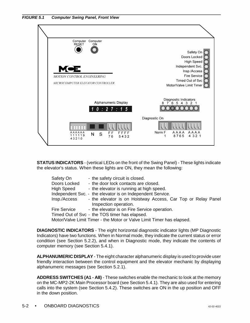
• ONBOARD DIAGNOSTICS 42-02-40225-2
FIGURE 5.1 Computer Swing Panel, Front View
STATUS INDICATORS - (vertical LEDs on the front of the Swing Panel) - These lights indicatethe elevator's status. When these lights are ON, they mean the following:
Safety On - the safety circuit is closed.Doors Locked - the door lock contacts are closed.High Speed - the elevator is running at high speed.Independent Svc. - the elevator is on Independent Service.Insp./Access - the elevator is on Hoistway Access, Car Top or Relay Panel
Inspection operation.Fire Service - the elevator is on Fire Service operation.Timed Out of Svc - the TOS timer has elapsed.Motor/Valve Limit Timer - the Motor or Valve Limit Timer has elapsed.
DIAGNOSTIC INDICATORS - The eight horizontal diagnostic indicator lights (MP DiagnosticIndicators) have two functions. When in Normal mode, they indicate the current status or errorcondition (see Section 5.2.2), and when in Diagnostic mode, they indicate the contents ofcomputer memory (see Section 5.4.1).
ALPHANUMERIC DISPLAY - The eight character alphanumeric display is used to provide userfriendly interaction between the control equipment and the elevator mechanic by displayingalphanumeric messages (see Section 5.2.1).
ADDRESS SWITCHES (A1 - A8) - These switches enable the mechanic to look at the memoryon the MC-MP2-2K Main Processor board (see Section 5.4.1). They are also used for enteringcalls into the system (see Section 5.4.2). These switches are ON in the up position and OFFin the down position.
42-02-4022 ONBOARD DIAGNOSTICS • 5-3
ADDRESS SWITCHES (A9 - A14) - These address switches, on the left side, are primarilyused by the factory.
FUNCTION SWITCH F1 (CAR A/CAR B) - This switch is used to access the COM Ports whenin SYSTEM mode. In a duplex configuration, this switch selects which car’s information is beingdisplayed and can be accessed by the A1 - A8 switches.
DIAGNOSTIC ON/NORMAL SWITCH - This switch puts the system in Diagnostic mode in theup position and in Normal mode in the down position (see Section 5.4).
FUNCTION SWITCHES (F2 - F7) - These switches are used to access diagnostic informationfor viewing and changing settings in the Normal and System modes of operation (see Sections5.2 and 5.3).
PUSH-BUTTONS N AND S - These push-buttons are used in different diagnostic modes toscan through the choices available and to make selections.
CP COMPUTER ON INDICATOR LIGHT - The CP Computer ON LED on the optionalMC-CGP-4(8) board indicates that the Communication Processor board is functioning normallyand is completing its program loop successfully. The MC-CGP-4(8) board is equipped with anauto reset feature that will cause the elevator to go through a resetting process if, for anyreason, the program loop cannot be completed.
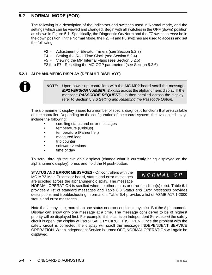
• ONBOARD DIAGNOSTICS 42-02-40225-4
NOTE: Upon power up, controllers with the MC-MP2 board scroll the messageMP2 VERSION NUMBER: 8.xx.xx across the alphanumeric display. If themessage PASSCODE REQUEST... is then scrolled across the display,refer to Section 5.3.6 Setting and Resetting the Passcode Option.
N O R M A L O P
5.2 NORMAL MODE (EOD)
The following is a description of the indicators and switches used in Normal mode, and thesettings which can be viewed and changed. Begin with all switches in the OFF (down) positionas shown in Figure 5.1. Specifically, the Diagnostic On/Norm and the F7 switches must be inthe down position. In the Normal Mode, the F2, F4 and F5 switches are used to access and setthe following:
F2 - Adjustment of Elevator Timers (see Section 5.2.3)F4 - Setting the Real Time Clock (see Section 5.2.4)F5 - Viewing the MP Internal Flags (see Section 5.2.5)F2 thru F7 - Resetting the MC-CGP parameters (see Section 5.2.6)
5.2.1 ALPHANUMERIC DISPLAY (DEFAULT DISPLAYS)
The alphanumeric display is used for a number of special diagnostic functions that are availableon the controller. Depending on the configuration of the control system, the available displaysinclude the following:
• scrolling status and error messages• temperature (Celsius) • temperature (Fahrenheit) • measured load• trip counter • software versions• time of day
To scroll through the available displays (change what is currently being displayed on thealphanumeric display), press and hold the N push-button.
STATUS AND ERROR MESSAGES - On controllers with theMC-MP2 Main Processor board, status and error messagesare scrolled across the alphanumeric display. The messageNORMAL OPERATION is scrolled when no other status or error condition(s) exist. Table 6.1provides a list of standard messages and Table 6.3 Status and Error Messages providesdescriptions and troubleshooting information. Table 6.4 provides a list of ASME A17.1-2000status and error messages.
Note that at any time, more than one status or error condition may exist. But the AlphanumericDisplay can show only one message at a time. The message considered to be of highestpriority will be displayed first. For example, if the car is on Independent Service and the safetycircuit is open, the display will scroll SAFETY CIRCUIT IS OPEN. Once the problem with thesafety circuit is corrected, the display will scroll the message INDEPENDENT SERVICEOPERATION. When Independent Service is turned OFF, NORMAL OPERATION will again bedisplayed.
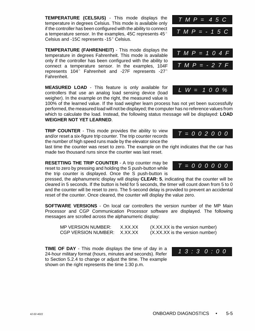
42-02-4022 ONBOARD DIAGNOSTICS • 5-5
T M P = 4 5 C
T M P = - 1 5 C
T M P = 1 0 4 F
T M P = - 2 7 F
L W = 1 0 0 %
T = 0 0 2 0 0 0
T = 0 0 0 0 0 0
1 3 : 3 0 : 0 0
TEMPERATURE (CELSIUS) - This mode displays thetemperature in degrees Celsius. This mode is available onlyif the controller has been configured with the ability to connecta temperature sensor. In the examples, 45C represents 45ECelsius and -15C represents -15E Celsius.
TEMPERATURE (FAHRENHEIT) - This mode displays thetemperature in degrees Fahrenheit. This mode is availableonly if the controller has been configured with the ability toconnect a temperature sensor. In the examples, 104Frepresents 104E Fahrenheit and -27F represents -27EFahrenheit.
MEASURED LOAD - This feature is only available forcontrollers that use an analog load sensing device (loadweigher). In the example on the right, the measured value is100% of the learned value. If the load weigher learn process has not yet been successfullyperformed, the measured load will not be displayed; the computer has no reference values fromwhich to calculate the load. Instead, the following status message will be displayed: LOADWEIGHER NOT YET LEARNED.
TRIP COUNTER - This mode provides the ability to viewand/or reset a six-figure trip counter. The trip counter recordsthe number of high speed runs made by the elevator since thelast time the counter was reset to zero. The example on the right indicates that the car hasmade two thousand runs since the counter was last reset.
RESETTING THE TRIP COUNTER - A trip counter may bereset to zero by pressing and holding the S push-button whilethe trip counter is displayed. Once the S push-button ispressed, the alphanumeric display will display CLEAR: 5, indicating that the counter will becleared in 5 seconds. If the button is held for 5 seconds, the timer will count down from 5 to 0and the counter will be reset to zero. The 5-second delay is provided to prevent an accidentalreset of the counter. Once cleared, the counter will display the value zero.
SOFTWARE VERSIONS - On local car controllers the version number of the MP MainProcessor and CGP Communication Processor software are displayed. The followingmessages are scrolled across the alphanumeric display:
MP VERSION NUMBER: X.XX.XX (X.XX.XX is the version number)CGP VERSION NUMBER: X.XX.XX (X.XX.XX is the version number)
TIME OF DAY - This mode displays the time of day in a24-hour military format (hours, minutes and seconds). Referto Section 5.2.4 to change or adjust the time. The exampleshown on the right represents the time 1:30 p.m.
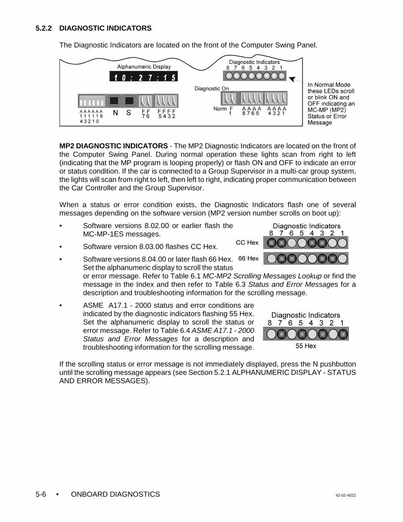
• ONBOARD DIAGNOSTICS 42-02-40225-6
5.2.2 DIAGNOSTIC INDICATORS
The Diagnostic Indicators are located on the front of the Computer Swing Panel.
MP2 DIAGNOSTIC INDICATORS - The MP2 Diagnostic Indicators are located on the front ofthe Computer Swing Panel. During normal operation these lights scan from right to left(indicating that the MP program is looping properly) or flash ON and OFF to indicate an erroror status condition. If the car is connected to a Group Supervisor in a multi-car group system,the lights will scan from right to left, then left to right, indicating proper communication betweenthe Car Controller and the Group Supervisor.
When a status or error condition exists, the Diagnostic Indicators flash one of severalmessages depending on the software version (MP2 version number scrolls on boot up):
• Software versions 8.02.00 or earlier flash theMC-MP-1ES messages.
• Software version 8.03.00 flashes CC Hex.
• Software versions 8.04.00 or later flash 66 Hex.Set the alphanumeric display to scroll the statusor error message. Refer to Table 6.1 MC-MP2 Scrolling Messages Lookup or find themessage in the Index and then refer to Table 6.3 Status and Error Messages for adescription and troubleshooting information for the scrolling message.
• ASME A17.1 - 2000 status and error conditions areindicated by the diagnostic indicators flashing 55 Hex.Set the alphanumeric display to scroll the status orerror message. Refer to Table 6.4 ASME A17.1 - 2000Status and Error Messages for a description andtroubleshooting information for the scrolling message.
If the scrolling status or error message is not immediately displayed, press the N pushbuttonuntil the scrolling message appears (see Section 5.2.1 ALPHANUMERIC DISPLAY - STATUSAND ERROR MESSAGES).
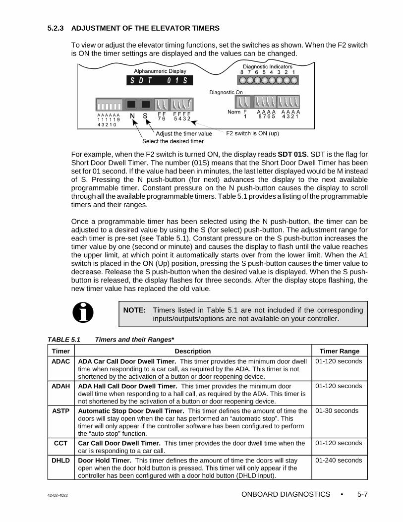
42-02-4022 ONBOARD DIAGNOSTICS • 5-7
NOTE: Timers listed in Table 5.1 are not included if the correspondinginputs/outputs/options are not available on your controller.
5.2.3 ADJUSTMENT OF THE ELEVATOR TIMERS
To view or adjust the elevator timing functions, set the switches as shown. When the F2 switchis ON the timer settings are displayed and the values can be changed.
For example, when the F2 switch is turned ON, the display reads SDT 01S. SDT is the flag forShort Door Dwell Timer. The number (01S) means that the Short Door Dwell Timer has beenset for 01 second. If the value had been in minutes, the last letter displayed would be M insteadof S. Pressing the N push-button (for next) advances the display to the next availableprogrammable timer. Constant pressure on the N push-button causes the display to scrollthrough all the available programmable timers. Table 5.1 provides a listing of the programmabletimers and their ranges.
Once a programmable timer has been selected using the N push-button, the timer can beadjusted to a desired value by using the S (for select) push-button. The adjustment range foreach timer is pre-set (see Table 5.1). Constant pressure on the S push-button increases thetimer value by one (second or minute) and causes the display to flash until the value reachesthe upper limit, at which point it automatically starts over from the lower limit. When the A1switch is placed in the ON (Up) position, pressing the S push-button causes the timer value todecrease. Release the S push-button when the desired value is displayed. When the S push-button is released, the display flashes for three seconds. After the display stops flashing, thenew timer value has replaced the old value.
TABLE 5.1 Timers and their Ranges*
Timer Description Timer Range
ADAC ADA Car Call Door Dwell Timer. This timer provides the minimum door dwelltime when responding to a car call, as required by the ADA. This timer is notshortened by the activation of a button or door reopening device.
01-120 seconds
ADAH ADA Hall Call Door Dwell Timer. This timer provides the minimum doordwell time when responding to a hall call, as required by the ADA. This timer isnot shortened by the activation of a button or door reopening device.
01-120 seconds
ASTP Automatic Stop Door Dwell Timer. This timer defines the amount of time thedoors will stay open when the car has performed an “automatic stop”. Thistimer will only appear if the controller software has been configured to performthe “auto stop” function.
01-30 seconds
CCT Car Call Door Dwell Timer. This timer provides the door dwell time when thecar is responding to a car call.
01-120 seconds
DHLD Door Hold Timer. This timer defines the amount of time the doors will stayopen when the door hold button is pressed. This timer will only appear if thecontroller has been configured with a door hold button (DHLD input).
01-240 seconds
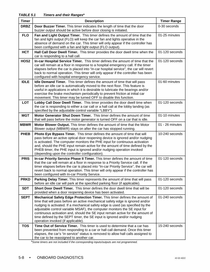
TABLE 5.1 Timers and their Ranges*
Timer Description Timer Range
• ONBOARD DIAGNOSTICS 42-02-40225-8
DRBZ Door Buzzer Timer. This timer indicates the length of time that the doorbuzzer output should be active before door closing is initiated.
0-30 seconds
FLO Fan and Light Output Timer. This timer defines the amount of time that thefan and light output (FLO) will keep the car fan and lights operative in theabsence of demand on the car. This timer will only appear if the controller hasbeen configured with a fan and light output (FLO output).
01-25 minutes
HCT Hall Call Door Dwell Timer. This timer provides the door dwell time when thecar is responding to a hall call.
01-120 seconds
HOS2 In-car Hospital Service Timer. This timer defines the amount of time that thecar will remain at a floor in response to a hospital emergency call. If the timerelapses before the car is placed into “in-car hospital service”, the car will revertback to normal operation. This timer will only appear if the controller has beenconfigured with hospital emergency service.
01-120 seconds
IDLE Idle Demand Timer. This timer defines the amount of time that will passbefore an idle car is automatically moved to the next floor. This feature isuseful in applications in which it is desirable to lubricate the bearings and/orexercise the brake mechanism periodically to prevent friction at initial carmovement. This timer may be turned OFF to disable this function.
01-60 minutes
LOT Lobby Call Door Dwell Timer. This timer provides the door dwell time whenthe car is responding to either a car call or a hall call at the lobby landing (asspecified by the adjustable control variable “LBBY”).
01-120 seconds
MGT Motor Generator Shut Down Timer. This timer defines the amount of timethat will pass before the motor generator is turned OFF on a car that is idle.
01-10 minutes
MBWR Motor Blower Output. This timer defines the amount of time that the MotorBlower output (MBWR) stays on after the car has stopped running.
01 - 26 minutes
PHEB Photo Eye Bypass Timer. This timer defines the amount of time that willpass before an active optical door reopening device is ignored and/or nudgingis activated. The computer monitors the PHE input for continuous activationand, should the PHE input remain active for the amount of time defined by thePHEB timer, the PHE input is ignored and/or nudging operation invoked(depending upon the controller configuration).
10-240 seconds
PRIS In-car Priority Service Phase II Timer. This timer defines the amount of timethat the car will remain at a floor in response to a Priority Service call. If thetimer elapses before the car is placed into “In-car Priority Service”, the car willrevert back to normal operation. This timer will only appear if the controller hasbeen configured with In-car Priority Service.
01-120 seconds
PRKD Parking Delay Timer. This timer represents the amount of time that will passbefore an idle car will park at the specified parking floor (if applicable).
01-120 seconds
SDT Short Door Dwell Timer. This timer defines the door dwell time that will beprovided when a door reopening device has been activated.
01-120 seconds
SEPT Mechanical Safety Edge Protection Timer. This timer defines the amount oftime that will pass before an active mechanical safety edge is ignored and/ornudging is activated. If a mechanical safety edge is used (as specified by theadjustable control variable MSAF), the computer monitors the SE input forcontinuous activation and, should the SE input remain active for the amount oftime defined by the SEPT timer, the SE input is ignored and/or nudgingoperation invoked (if applicable).
01-240 seconds
TOS Time Out of Service Timer. This timer is used to determine that a car hasbeen prevented from responding to a car or hall call demand. Once this timerelapses, the car’s “in service” status is removed to allow hall calls assigned tothe car to be reassigned to another car.
15-240 seconds
*Some timers are not included if the corresponding inputs/outputs are not programmed.
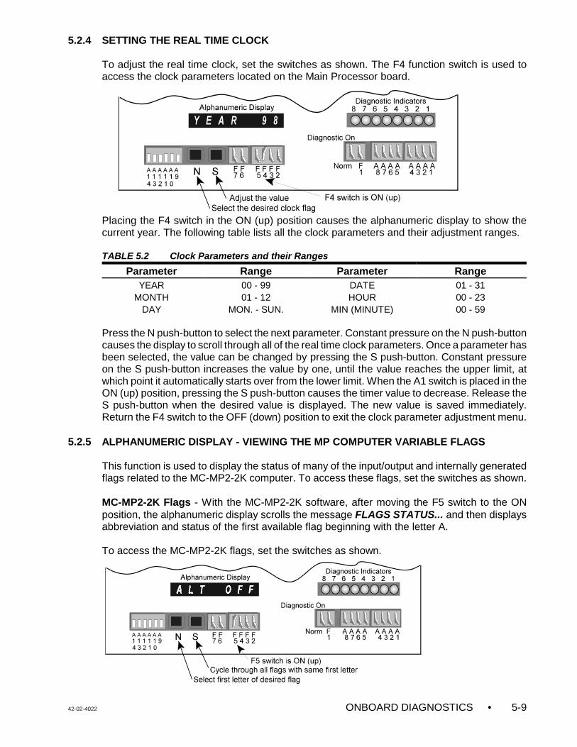
42-02-4022 ONBOARD DIAGNOSTICS • 5-9
5.2.4 SETTING THE REAL TIME CLOCK
To adjust the real time clock, set the switches as shown. The F4 function switch is used toaccess the clock parameters located on the Main Processor board.
Placing the F4 switch in the ON (up) position causes the alphanumeric display to show thecurrent year. The following table lists all the clock parameters and their adjustment ranges.
TABLE 5.2 Clock Parameters and their Ranges
Parameter Range Parameter RangeYEAR 00 - 99 DATE 01 - 31
MONTH 01 - 12 HOUR 00 - 23DAY MON. - SUN. MIN (MINUTE) 00 - 59
Press the N push-button to select the next parameter. Constant pressure on the N push-buttoncauses the display to scroll through all of the real time clock parameters. Once a parameter hasbeen selected, the value can be changed by pressing the S push-button. Constant pressureon the S push-button increases the value by one, until the value reaches the upper limit, atwhich point it automatically starts over from the lower limit. When the A1 switch is placed in theON (up) position, pressing the S push-button causes the timer value to decrease. Release theS push-button when the desired value is displayed. The new value is saved immediately.Return the F4 switch to the OFF (down) position to exit the clock parameter adjustment menu.
5.2.5 ALPHANUMERIC DISPLAY - VIEWING THE MP COMPUTER VARIABLE FLAGS
This function is used to display the status of many of the input/output and internally generatedflags related to the MC-MP2-2K computer. To access these flags, set the switches as shown.
MC-MP2-2K Flags - With the MC-MP2-2K software, after moving the F5 switch to the ONposition, the alphanumeric display scrolls the message FLAGS STATUS... and then displaysabbreviation and status of the first available flag beginning with the letter A.
To access the MC-MP2-2K flags, set the switches as shown.
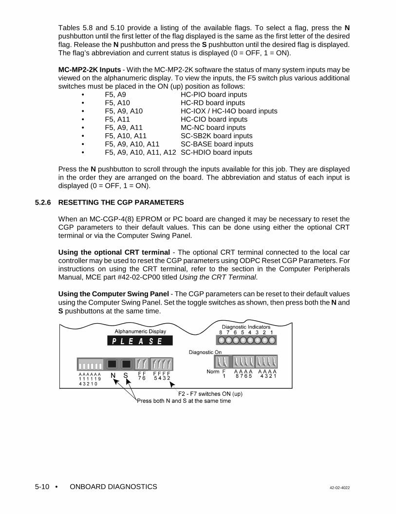
• ONBOARD DIAGNOSTICS 42-02-40225-10
Tables 5.8 and 5.10 provide a listing of the available flags. To select a flag, press the Npushbutton until the first letter of the flag displayed is the same as the first letter of the desiredflag. Release the N pushbutton and press the S pushbutton until the desired flag is displayed.The flag’s abbreviation and current status is displayed (0 = OFF, 1 = ON).
MC-MP2-2K Inputs - With the MC-MP2-2K software the status of many system inputs may beviewed on the alphanumeric display. To view the inputs, the F5 switch plus various additionalswitches must be placed in the ON (up) position as follows:
• F5, A9 HC-PIO board inputs• F5, A10 HC-RD board inputs• F5, A9, A10 HC-IOX / HC-I4O board inputs• F5, A11 HC-CIO board inputs• F5, A9, A11 MC-NC board inputs• F5, A10, A11 SC-SB2K board inputs• F5, A9, A10, A11 SC-BASE board inputs• F5, A9, A10, A11, A12 SC-HDIO board inputs
Press the N pushbutton to scroll through the inputs available for this job. They are displayedin the order they are arranged on the board. The abbreviation and status of each input isdisplayed (0 = OFF, 1 = ON).
5.2.6 RESETTING THE CGP PARAMETERS
When an MC-CGP-4(8) EPROM or PC board are changed it may be necessary to reset theCGP parameters to their default values. This can be done using either the optional CRTterminal or via the Computer Swing Panel.
Using the optional CRT terminal - The optional CRT terminal connected to the local carcontroller may be used to reset the CGP parameters using ODPC Reset CGP Parameters. Forinstructions on using the CRT terminal, refer to the section in the Computer PeripheralsManual, MCE part #42-02-CP00 titled Using the CRT Terminal.
Using the Computer Swing Panel - The CGP parameters can be reset to their default valuesusing the Computer Swing Panel. Set the toggle switches as shown, then press both the N andS pushbuttons at the same time.
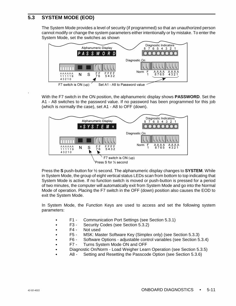
42-02-4022 ONBOARD DIAGNOSTICS • 5-11
5.3 SYSTEM MODE (EOD)
The System Mode provides a level of security (if programmed) so that an unauthorized personcannot modify or change the system parameters either intentionally or by mistake. To enter theSystem Mode, set the switches as shown
.With the F7 switch in the ON position, the alphanumeric display shows PASSWORD. Set theA1 - A8 switches to the password value. If no password has been programmed for this job(which is normally the case), set A1 - A8 to OFF (down).
Press the S push-button for ½ second. The alphanumeric display changes to SYSTEM. Whilein System Mode, the group of eight vertical status LEDs scan from bottom to top indicating thatSystem Mode is active. If no function switch is moved or push-button is pressed for a periodof two minutes, the computer will automatically exit from System Mode and go into the NormalMode of operation. Placing the F7 switch in the OFF (down) position also causes the EOD toexit the System Mode.
In System Mode, the Function Keys are used to access and set the following systemparameters:
C F1 - Communication Port Settings (see Section 5.3.1)C F3 - Security Codes (see Section 5.3.2)C F4 - Not usedC F5 - MSK: Master Software Key (Simplex only) (see Section 5.3.3)C F6 - Software Options - adjustable control variables (see Section 5.3.4)C F7 - Turns System Mode ON and OFFC Diagnostic On/Norm - Load Weigher Learn Operation (see Section 5.3.5)C A8 - Setting and Resetting the Passcode Option (see Section 5.3.6)
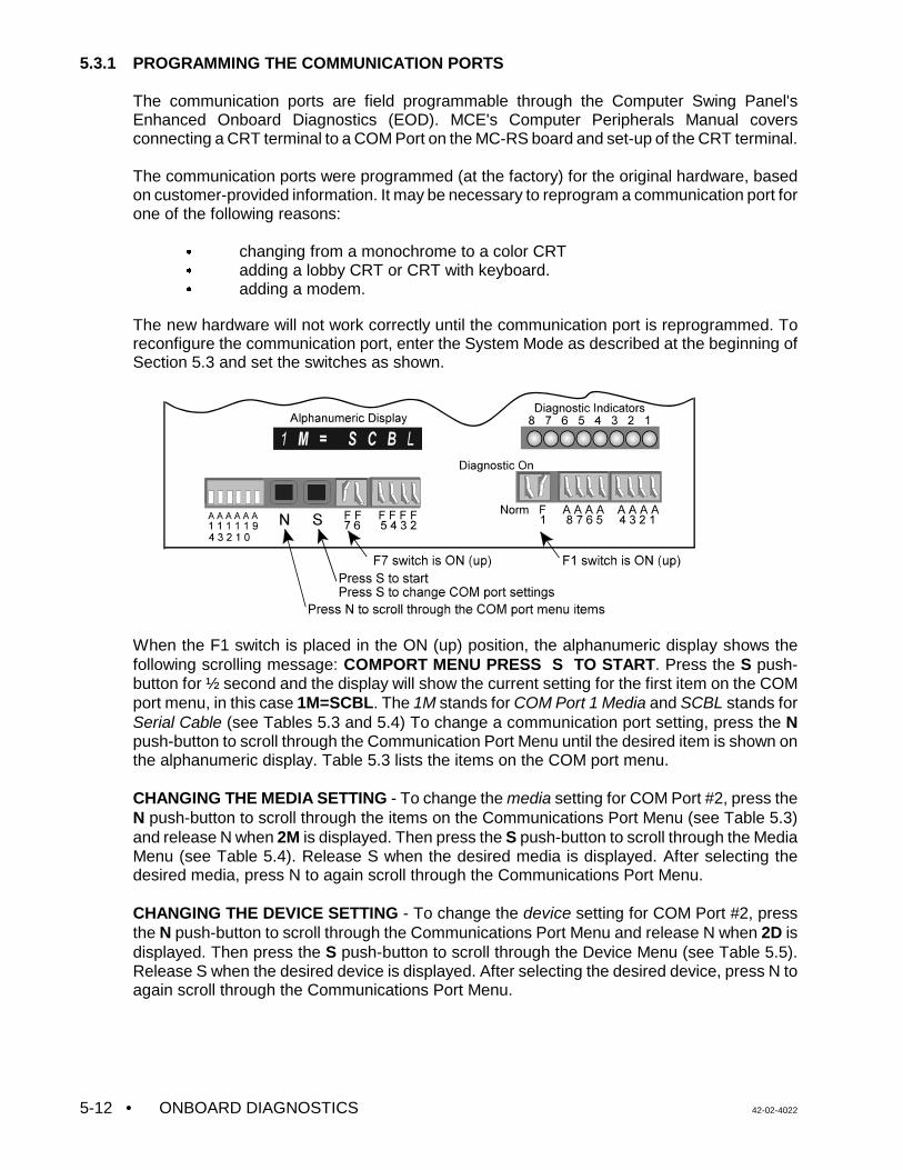
• ONBOARD DIAGNOSTICS 42-02-40225-12
5.3.1 PROGRAMMING THE COMMUNICATION PORTS
The communication ports are field programmable through the Computer Swing Panel'sEnhanced Onboard Diagnostics (EOD). MCE's Computer Peripherals Manual coversconnecting a CRT terminal to a COM Port on the MC-RS board and set-up of the CRT terminal.
The communication ports were programmed (at the factory) for the original hardware, basedon customer-provided information. It may be necessary to reprogram a communication port forone of the following reasons:
C changing from a monochrome to a color CRTC adding a lobby CRT or CRT with keyboard.C adding a modem.
The new hardware will not work correctly until the communication port is reprogrammed. Toreconfigure the communication port, enter the System Mode as described at the beginning ofSection 5.3 and set the switches as shown.
When the F1 switch is placed in the ON (up) position, the alphanumeric display shows thefollowing scrolling message: COMPORT MENU PRESS S TO START. Press the S push-button for ½ second and the display will show the current setting for the first item on the COMport menu, in this case 1M=SCBL. The 1M stands for COM Port 1 Media and SCBL stands forSerial Cable (see Tables 5.3 and 5.4) To change a communication port setting, press the Npush-button to scroll through the Communication Port Menu until the desired item is shown onthe alphanumeric display. Table 5.3 lists the items on the COM port menu.
CHANGING THE MEDIA SETTING - To change the media setting for COM Port #2, press theN push-button to scroll through the items on the Communications Port Menu (see Table 5.3)and release N when 2M is displayed. Then press the S push-button to scroll through the MediaMenu (see Table 5.4). Release S when the desired media is displayed. After selecting thedesired media, press N to again scroll through the Communications Port Menu.
CHANGING THE DEVICE SETTING - To change the device setting for COM Port #2, pressthe N push-button to scroll through the Communications Port Menu and release N when 2D isdisplayed. Then press the S push-button to scroll through the Device Menu (see Table 5.5).Release S when the desired device is displayed. After selecting the desired device, press N toagain scroll through the Communications Port Menu.
42-02-4022 ONBOARD DIAGNOSTICS • 5-13
SAVING THE CHANGES - When you have finished making changes, press the N push-buttonuntil, SAVE?N/S is displayed. Pressing S will save the changes and SAVED... will be displayed.If N is pressed the program will continue to scroll through the Communications Port Menu. Toexit the Communications Port Menu, place the F1 switch in the OFF (down) position. If you exitthe Communication Port Menu without choosing SAVE?N/S and pressing S, any changes madeto settings will be ignored.
TABLE 5.3 Communication Port Menu
EOD Display Description
NO COM No COM port option has been enabled1M COM Port 1 Media1D COM Port 1 Device2M COM Port 2 Media2D COM Port 2 Device3M COM Port 3 Media3D COM Port 3 Device4M COM Port 4 Media4D COM Port 4 Device
SEVEN/S Save the changes? N for no or continue, S for save
TABLE 5.4 Media Menu
EOD Display Description
NONE NO MEDIA - Select when removing a computer terminal from a port.SCBL SERIAL CABLE - Select when setting up a CRT/terminal with a keyboard.LDRV LINE DRIVER - Used when setting up a CRT at a distance over 40 feet.MODM MODEM - Select when attaching a modem to a computer.
TABLE 5.5 Device Menu
EOD Display Description
NONE No Device
CRTMKUse for these terminals or emulators with keyboard (Link MC5, Wyse WY-325ES, Esprit 250C Emulator or ADDS 260LF Emulator)
CRTMUse for these terminals or emulators without keyboard (Link MC5, Wyse WY-325ES, Esprit 250C Emulator or ADDS 260LF Emulator)
PC Personal Computer with CMS / MSD
PCGD Personal Computer Graphic Display (no longer used)
CRTCK Use for these terminals with keyboard (Link MC-70, Wyse WY-370)
CRTC Use for these terminals without keyboard (Link MC-70, Wyse WY-370)
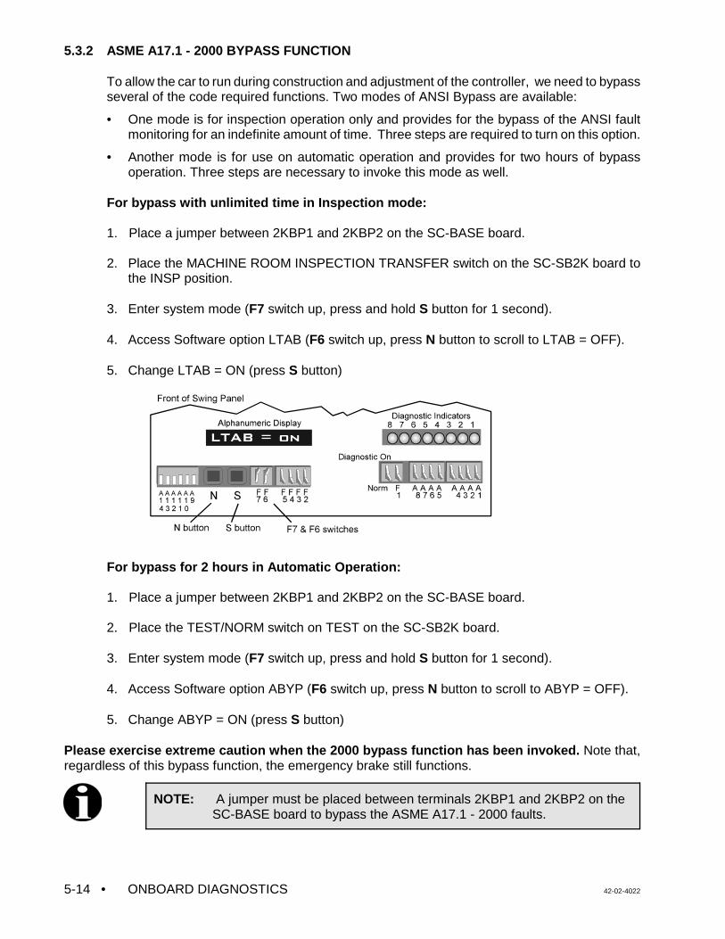
• ONBOARD DIAGNOSTICS 42-02-40225-14
NOTE: A jumper must be placed between terminals 2KBP1 and 2KBP2 on theSC-BASE board to bypass the ASME A17.1 - 2000 faults.
5.3.2 ASME A17.1 - 2000 BYPASS FUNCTION
To allow the car to run during construction and adjustment of the controller, we need to bypassseveral of the code required functions. Two modes of ANSI Bypass are available:
• One mode is for inspection operation only and provides for the bypass of the ANSI faultmonitoring for an indefinite amount of time. Three steps are required to turn on this option.
• Another mode is for use on automatic operation and provides for two hours of bypassoperation. Three steps are necessary to invoke this mode as well.
For bypass with unlimited time in Inspection mode:
1. Place a jumper between 2KBP1 and 2KBP2 on the SC-BASE board.
2. Place the MACHINE ROOM INSPECTION TRANSFER switch on the SC-SB2K board tothe INSP position.
3. Enter system mode (F7 switch up, press and hold S button for 1 second).
4. Access Software option LTAB (F6 switch up, press N button to scroll to LTAB = OFF).
5. Change LTAB = ON (press S button)
For bypass for 2 hours in Automatic Operation:
1. Place a jumper between 2KBP1 and 2KBP2 on the SC-BASE board.
2. Place the TEST/NORM switch on TEST on the SC-SB2K board.
3. Enter system mode (F7 switch up, press and hold S button for 1 second).
4. Access Software option ABYP (F6 switch up, press N button to scroll to ABYP = OFF).
5. Change ABYP = ON (press S button)
Please exercise extreme caution when the 2000 bypass function has been invoked. Note that,regardless of this bypass function, the emergency brake still functions.
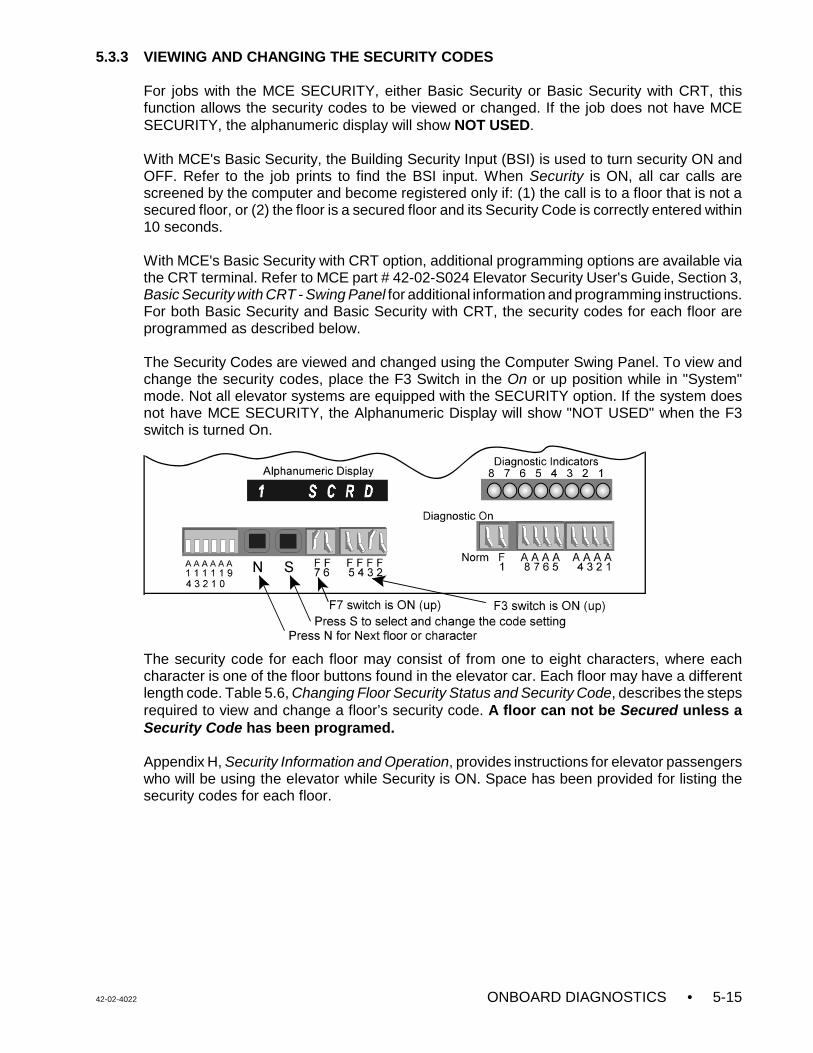
42-02-4022 ONBOARD DIAGNOSTICS • 5-15
5.3.3 VIEWING AND CHANGING THE SECURITY CODES
For jobs with the MCE SECURITY, either Basic Security or Basic Security with CRT, thisfunction allows the security codes to be viewed or changed. If the job does not have MCESECURITY, the alphanumeric display will show NOT USED.
With MCE's Basic Security, the Building Security Input (BSI) is used to turn security ON andOFF. Refer to the job prints to find the BSI input. When Security is ON, all car calls arescreened by the computer and become registered only if: (1) the call is to a floor that is not asecured floor, or (2) the floor is a secured floor and its Security Code is correctly entered within10 seconds.
With MCE's Basic Security with CRT option, additional programming options are available viathe CRT terminal. Refer to MCE part # 42-02-S024 Elevator Security User's Guide, Section 3,Basic Security with CRT - Swing Panel for additional information and programming instructions.For both Basic Security and Basic Security with CRT, the security codes for each floor areprogrammed as described below.
The Security Codes are viewed and changed using the Computer Swing Panel. To view andchange the security codes, place the F3 Switch in the On or up position while in "System"mode. Not all elevator systems are equipped with the SECURITY option. If the system doesnot have MCE SECURITY, the Alphanumeric Display will show "NOT USED" when the F3switch is turned On.
The security code for each floor may consist of from one to eight characters, where eachcharacter is one of the floor buttons found in the elevator car. Each floor may have a differentlength code. Table 5.6, Changing Floor Security Status and Security Code, describes the stepsrequired to view and change a floor’s security code. A floor can not be Secured unless aSecurity Code has been programed.
Appendix H, Security Information and Operation, provides instructions for elevator passengerswho will be using the elevator while Security is ON. Space has been provided for listing thesecurity codes for each floor.
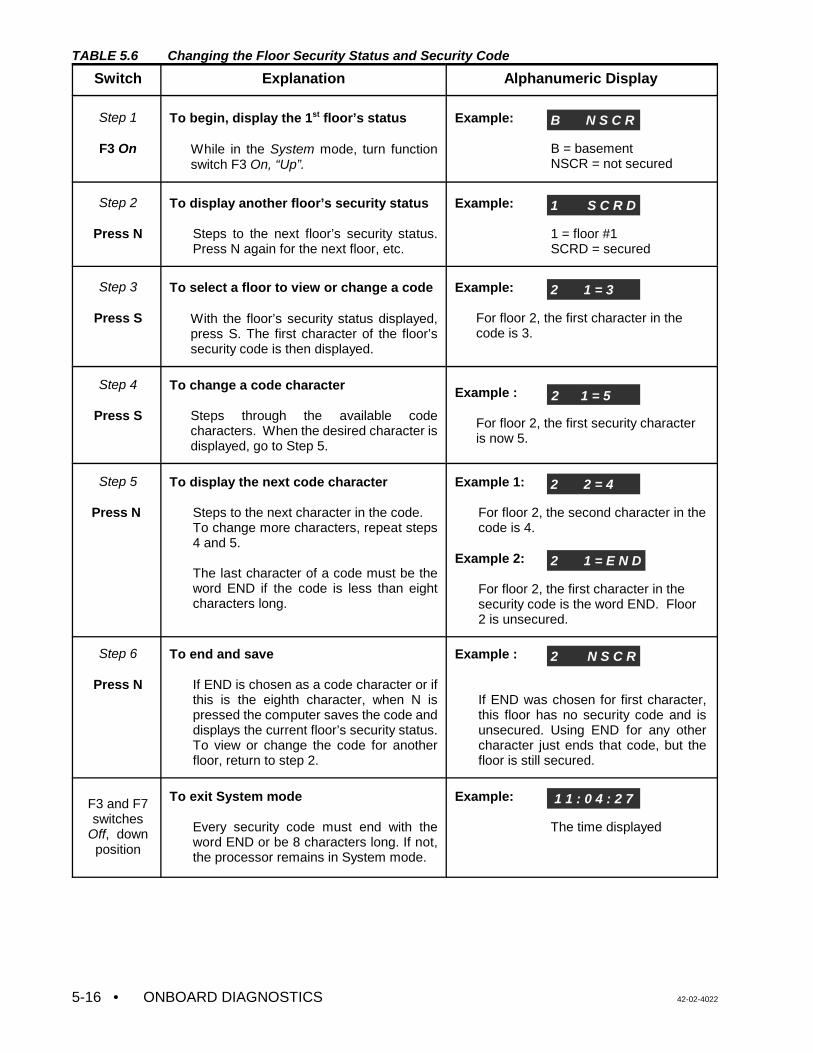
• ONBOARD DIAGNOSTICS 42-02-40225-16
TABLE 5.6 Changing the Floor Security Status and Security Code
Switch Explanation Alphanumeric Display
Step 1
F3 On
To begin, display the 1st floor’s status
While in the System mode, turn functionswitch F3 On, “Up”.
Example:
B = basementNSCR = not secured
Step 2
Press N
To display another floor’s security status
Steps to the next floor’s security status.Press N again for the next floor, etc.
Example:
1 = floor #1SCRD = secured
Step 3
Press S
To select a floor to view or change a code
With the floor’s security status displayed,press S. The first character of the floor’ssecurity code is then displayed.
Example:
For floor 2, the first character in thecode is 3.
Step 4
Press S
To change a code character
Steps through the available codecharacters. When the desired character isdisplayed, go to Step 5.
Example :
For floor 2, the first security characteris now 5.
Step 5
Press N
To display the next code character
Steps to the next character in the code. To change more characters, repeat steps4 and 5.
The last character of a code must be theword END if the code is less than eightcharacters long.
Example 1:
For floor 2, the second character in thecode is 4.
Example 2:
For floor 2, the first character in thesecurity code is the word END. Floor2 is unsecured.
Step 6
Press N
To end and save
If END is chosen as a code character or ifthis is the eighth character, when N ispressed the computer saves the code anddisplays the current floor’s security status.To view or change the code for anotherfloor, return to step 2.
Example :
If END was chosen for first character,this floor has no security code and isunsecured. Using END for any othercharacter just ends that code, but thefloor is still secured.
F3 and F7switches
Off, downposition
To exit System mode
Every security code must end with theword END or be 8 characters long. If not,the processor remains in System mode.
Example:
The time displayed
B N S C R
1 S C R D
2 1 = 3
2 1 = 5
2 2 = 4
2 1 = E N D
2 N S C R
1 1 : 0 4 : 2 7
42-02-4022 ONBOARD DIAGNOSTICS • 5-17
5.3.4 SETTING MSK: MASTER SOFTWARE KEY
On a simplex car, the Master Software Key is used in conjunction with the Basic Security withCRT option. To view or change MSK, log into System Mode as described at the beginning ofSection 5.3 and then place the F5 switch in the ON (Up) position. If this is not a simplex car orif this job does not have Basic Security with CRT enabled, the alphanumeric display will showNOT USED. Additional information about the Master Software Key (MSK) can be found in MCEPart # 42-02-S024 Elevator Security User's Guide, Section 3, Basic Security with CRT - SwingPanel.
5.3.5 SETTING THE SOFTWARE OPTIONS - ADJUSTABLE CONTROL VARIABLES
Table 5.7 provides a listing of the software options - adjustable control variables. Not all of theoptions are available on all controllers. To view or set the adjustable control variables, log intoSystem Mode as described at the beginning of Section 5.3 and place the F6 switch in the ON(Up) position.
The first available variable will be shown on the display. Press the S push-button to change thesetting. Press the N push-button to scroll to the next available variable. Table 5.7 lists thevariables in alphabetic order, not in the order in which they are displayed on the controller.
TABLE 5.7 Software Options
VARIABLE NAME DEFINITIONABYP A17.1 - 2000 Bypass Allows the car to run without A17.1 - 2000 (monitor for 2 hours).
AFR Alternate Fire Floor Recall Determine the designated recall floor for alternate Fire Service Operation.
AFR2 Second Alternate FireFloor Recall
Determine the designated recall floor for the second alternate Fire Service operation(Detroit Fire code).
AGNG Alternate Gong Option Causes an arrival lantern to be illuminated whenever the car's doors are open at anon-lobby landing. In the absence of actual call demand, the direction selected is areflection of the car's last direction of travel. If the car is located at a terminal landing,the appropriate lantern will be illuminated.
APP1 Alternate Primary (lower)Parking Floor
When on, the car will no longer park at the original parking floor (PPF). Instead the carwill park at the first alternate parking floor specified by the landing stored in thisvariable.
APP2 Alternate Primary (lower)Parking Floor #2
When ON, the car will no longer park at the original parking floor (PPF). Instead thecar will park at the second alternate parking floor specified by the landing stored in thisvariable.
ASP1 Alternate Secondary(upper) Parking Floor
When ON, the car will no longer park at the original secondary parking floor (SPF).Instead the car will park at the secondary parking floor specified by the landing storedin this variable. This variable is only available on a duplex system.
ASP2 Alternate Secondary(upper) Parking Floor #2
When ON, the car will no longer park at the original secondary parking floor (SPF).Instead the car will park at the secondary parking floor specified by the landing storedin this variable. This variable is only available on a duplex system.
CCBC Cancel Car Call BehindCar Option
If ON, and if the car has a direction arrow (SUA/SDA), no car calls can be registeredbehind the car's current position. For example, if a car is at the fifth floor, movingdown, then no car calls can be registered for any floors above the fifth floor.
CNID Car Network ID (A thru L) The Car Network ID identifies this controller to the Group Supervisor.
CPPB Constant/MomentaryPressure PhotoEye/Safety Edge Bypass
This option, when turned “OFF”, will disable photo eye/safety edge bypass logic forcars that are on Independent Service, Attendant Service, Hospital Service Phase 2,and any other non-automatic door closing conditions (CPCLOSE, MPCLOSE, etc.).
CSAR CSA Redundancy CheckOption
When ON, CSA redundancy checking logic is invoked. When OFF, the LSR, CNP andUDF inputs are ignored, and CSA redundancy checking logic is not performed.
DCFL Door Close Front Latch Maintains the Door Close Function on the front doors continuously as long as a dooropen command is absent.
DCRL Door Close Rear Latch Maintains the Door Close Function on the rear doors continuously as long as a dooropen command is absent.
DDOP Double Ding on DownOption
When ON, the gong output dings twice for down direction travel and once for updirection travel. If OFF, the gong output will only ding once for both up and downdirection of travel.
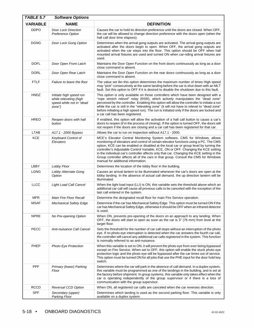
TABLE 5.7 Software Options
VARIABLE NAME DEFINITION
• ONBOARD DIAGNOSTICS 42-02-40225-18
DDPO Door Lock DirectionPreference Option
Causes the car to hold its direction preference until the doors are closed. When OFF,the car will be allowed to change direction preference with the doors open (when thehall call door time elapses).
DGNG Door Lock Gong Option Determines when the arrival gong outputs are activated. The arrival gong outputs areactivated after the doors begin to open. When OFF, the arrival gong outputs areactivated when the car steps into the floor. This option should be OFF when hallmounted arrival fixtures are used and turned ON when car-riding arrival fixtures areused.
DOFL Door Open Front Latch Maintains the Door Open Function on the front doors continuously as long as a doorclose command is absent.
DORL Door Open Rear Latch Maintains the Door Open Function on the rear doors continuously as long as a doorclose command is absent.
FTLF Failure to leave the floor The value set ibn this option determines the maximum number of times High speedmay "pick" consecutively at the same landing before the car is shut down with an MLTfault. Set this option to OFF if it is desired to disable the shutdown due to this fault.
HNDZ Initiate high speed runwhile releveling (highspeed while not in “deadzone”)
This option is only available on those controllers which have been designed with a“rope stretch relevel” relay (RSR), which actively manipulates the “dead zone”perceived by the controller. Enabling this option will allow the controller to initiate a runwhile the car is still in the “releveling zone” (it will not have to relevel to “dead zone”before initiating a high speed run). The run is initiated only if the doors are locked anda car call has been registered.
HREO Reopen doors with hallbutton
If enabled, this option will allow the activation of a hall call button to cause a car’sdoors to reopen (if in the process of closing). If the option is turned OFF, the doors willnot reopen if the doors are closing and a car call has been registered for that car.
LTAB A17.1 - 2000 Bypass Allows the car to run on inspection without A17.1 - 2000.
KCE Keyboard Control ofElevators
MCE’s Elevator Central Monitoring System software, CMS for Windows, allowsmonitoring of elevators and control of certain elevator functions using a PC. The CMSoption, KCE can be enabled or disabled at the local car or group level by turning thecontroller’s Adjustable Control Variable, KCE, ON or OFF. Changing the KCE settingin the individual car’s controller affects only that car. Changing the KCE setting in theGroup controller affects all of the cars in that group. Consult the CMS for Windowsmanual for additional information.
LBBY Lobby Floor Determines the location of the lobby floor in the building.
LGNG Lobby Alternate GongOption
Causes an arrival lantern to be illuminated whenever the car's doors are open at thelobby landing. In the absence of actual call demand, the up direction lantern will beilluminated.
LLCC Light Load Call Cancel When the light load input (LLI) is ON, this variable sets the threshold above which anadditional car call will cause all previous calls to be canceled with the exception of thelast call entered in the system.
MFR Main Fire Floor Recall Determine the designated recall floor for main Fire Service operation.
MSAF Mechanical Safety Edge Determine if the car has Mechanical Safety Edge. This option must be turned ON if thecar has Mechanical Safety Edge, otherwise it should be OFF when an infrared detectoris used.
NPRE No Pre-opening Option When ON, prevents pre-opening of the doors on an approach to any landing. WhenOFF, the doors will start to open as soon as the car is 3" (76 mm) from level at thetarget floor.
PECC Anti-nuisance Call Cancel Sets the threshold for the number of car call stops without an interruption of the photoeye. If no photo eye interruption is detected when the car answers the fourth car call,the controller will cancel any additional car calls registered in the system. This functionis normally referred to as anti-nuisance.
PHEP Photo Eye Protection When this variable is set to ON, it will prevent the photo eye from ever being bypassedexcept on Fire Service. When set to OFF, this option will enable the stuck photo eyeprotection logic and the photo eye will be bypassed after the car times out of service.This option must be turned ON for all jobs that use the PHE input for the door hold keyswitch.
PPF Primary (lower) ParkingFloor
Determines where the car will park in the absence of call demand. In a duplex system,this variable must be programmed as one of the landings in the building, and is set atthe factory before shipment. In group systems, this variable only takes effect when thecar is operating independently of the group supervisor or if there is a loss ofcommunication with the group supervisor.
RCCD Reversal CCD Option When ON, all registered car calls are canceled when the car reverses direction.
SPF Secondary (upper)Parking Floor
Determines which landing is used as the second parking floor. This variable is onlyavailable on a duplex system.
42-02-4022 ONBOARD DIAGNOSTICS • 5-19
5.3.6 LOAD WEIGHER LEARN OPERATION (CALIBRATION)
The load weigher (isolated platform or crosshead deflection) provides a signal that correspondsto the perceived load. This signal is brought to the control system where it is conditioned,sampled and digitized, and the value is used to calculate the actual load inside the elevator.This load value is then used for logical operations such as anti-nuisance and hall call bypass.
With the isolated platform load weigher (MCE), the system simply learns the reference valuesof the empty and fully loaded car weight, which are then used to calculate the current load (asa percentage of full load). However, with the crosshead deflection load weigher (K-Tech), themagnitude of the signal generated by the load sensor represents the perceived load at thecrosshead, which includes the weight of the car itself, the load inside the car, the travelingcable, and any compensation cables that might be attached to the car. Therefore it isnecessary for the controller to use the measured load value in a calculation to determine theload inside the elevator (the raw load value cannot be used as is).
Due to the dynamics of the elevator system, the load represented by the traveling cable andcompensation cables will vary with the position of the car in the hoistway. The load weighingsystem accounts for these variances by performing a process which learns empty car and fullcar load values at each floor in the building. The load in the car can then be determined byreading the value at a given floor and, using the learned values for that floor, performing alinear interpolation to approximate the load inside the car (as a percentage of full load). Thecalculated load percentage is then used to initiate logical operations, i.e., hall call bypass at80% of capacity.
Logical operations that use the load information include: light load weighing (anti-nuisance),advance car dispatch (reduction of door dwell time), heavy load weighing (hall call bypass), andoverloaded car detection. Each threshold is user-programmable, and will determine when eachof these logical operations should be performed.
The measurement of the load will only take place when the car is stopped at a landing with thedoors open. This is the only time that we would anticipate a change in load upon which a logicaloperation should be initiated. The measurement is not taken when the car is running becausethe acceleration and deceleration of the car would be interpreted as a change in load.
Functional Description of Load Thresholds - The four load thresholds are:
C LLW (Light load weigher threshold): This threshold value is used to define the load atwhich a limited number of car calls is to be registered. If the programmed number of carcalls is exceeded, all car calls will be canceled.
Example: LLW=20%. If the measured load in the car is less than 20%, the computer willonly allow a certain number of car calls to be registered (defined by a field-programmable value LLCC). If LLCC is programmed at a value of 3, the computer willonly allow 3 calls to be registered if the load is less than 20%. If a fourth call isregistered, all car calls will be canceled.
C DLW (Dispatch load weigher threshold): This threshold value is used to define the loadat which the lobby landing door timer is reduced. This threshold should be set to a value(defined in many specifications as 60%) at which it is appropriate to initiate the processof moving the car out of the lobby.
C HLW (Heavy load weigher threshold): This threshold value is used to define the loadvalue at which hall calls should be bypassed.
• ONBOARD DIAGNOSTICS 42-02-40225-20
C OLW (Overloaded car threshold): This threshold value is used to define the load valueat which it is considered unsafe to move the elevator. When this threshold is exceeded,the car will remain at the floor with doors open. Typically an application that requiresOLW will use some type of visual and/or audible indicator to alert elevator passengersthat the car is overloaded.
C OLW2 (Overloaded car threshold 2): When on Fire Service, this threshold value is usedinstead of the OLW value (see OLW above).
Learn Modes - With the isolated platform load weigher (MCE), the system simply learns thereference values of the empty and fully loaded car weight. However, with the crossheaddeflection load weigher (K-Tech), the system must learn the reference values of empty and fullyloaded car weight at each floor. This is necessary because the perceived load at the crossheadvaries with the position of the car in the hoistway due to the changing proportion of the travelingcable hanging beneath the car and the position of the compensation cables. Examples of thecauses fo load variance include:
• The position of the traveling cable will present a varying load (a changing proportion ofthe traveling cable hanging directly beneath the car).
• The position of the compensation cables will present a varying load (a changingproportion of the compensation cable hanging directly beneath the car). Note that thecompensation cables are intended to equalize the load at the motor sheave, not at thecrosshead.
• Variances in the alignment of the hoistway guide rails will present varying amounts ofresistance to elevator movement. An added amount of resistance or friction may resultin an increased perceived load at the crosshead.
The values learned for the empty car and full car at a particular floor are used to calculate theload when the car is positioned at that floor.
The Learn Process - The learn process consists of three functions:
C Learning the measured load value for an empty car at each landing.
C Learning the measured load value for a fully loaded car at each landing.
C Establishing the load thresholds which will initiate the logical operations.
Each of these functions can be performed separately. All three functions must be performedbefore the load weigher system will perform properly. To enter the learn function, the carmust be placed on Independent Service. If an independent service switch is available in thecar, use it. If not, the car can be placed on Independent Service by connecting a jumperbetween terminals 2 and 49 on the controller main relay board. A further option is to use theTEST/NORM switch on the SC-SB2K relay board, but this will electrically disconnect the dooropen relays, and is therefore not recommended.
5.3.6.1 GETTING INTO LOAD WEIGHER LEARN MODE
a. Enter the SYSTEM mode of operation on the Computer Swing Panel by following thesteps described at the beginning of Section 5.3.
42-02-4022 ONBOARD DIAGNOSTICS • 5-21
b. Once in SYSTEM mode, access the load weigher learn function by turning theDiagnostic On switch ON (the F7 switch should remain in the ON position). Thecomputer will respond with one of three scrolling messages:
C NOT USED - The software has not been configured to provide the “analog loadweighing function”. Contact MCE if you believe this to be in error.
C CAR NOT READY TO LEARN - Verify that the car has been placed onIndependent Service.
C PRESS N FOR K-TECH CROSSHEAD OR S FOR MCE PLATFORM... - Selectthe type of load weigher by pressing N for K-Tech crosshead deflection or S forMCE isolated platform load weigher.
The following message is then displayed:
C ANALOG LOAD WEIGHER LEARN FUNCTION...PRESS N TO CONTINUE -The system is ready to learn, you have successfully placed the elevator in “loadweigher learn mode”.
c. Once the elevator has successfully been placed in “load weigher learn mode” one orall three of the learn functions can be performed as described in sections to follow. Thesystem will display one of three main prompts:
C READY TO LEARN EMPTY CAR VALUES? PRESS S TO CONFIRM - Pressthe S push-button to begin this process. The car must be empty beforebeginning.
C READY TO LEARN FULL CAR VALUES? PRESS S TO CONFIRM - Press theS push-button to begin this process. Place the full load weights in the car beforebeginning.
C ADJUST THE LOAD THRESHOLDS? PRESS S TO CONFIRM - Press the Spush-button to adjust the load threshold values.
Press the N push-button to cycle through these three different prompts. To exit the loadweigher learn mode, turn the Diagnostic On function switch on the computer SwingPanel to OFF.
5.3.6.2 LEARNING THE EMPTY AND FULLY LOADED CAR VALUES
Learning the empty and loaded car values is an automated process that requires only that theappropriate load be present in the car before beginning each process. It is best to have twopersons available, one in the machine room at the elevator controller and one positionedat a floor with test weights available. The test weights must represent the full load value.
If the K-Tech crosshead deflection load weigher was selected, the learn process willautomatically run the car from floor to floor, stopping at each landing. The car will first travel tothe bottom landing, stop and pause there for a period of time. The car will then move in the UPdirection, stopping at each floor on the way to the car's highest landing served. Each time thecar stops at a landing a value is learned for that landing (either the empty or full load value).Once all floors have been learned, the car will automatically return to its point of origin andopen its doors. The learn process must be performed twice, once for empty car load and oncefor full car load.
• ONBOARD DIAGNOSTICS 42-02-40225-22
Learning the Empty Car Load Values:
a. With the system in “load weigher learn mode”, press the N push-button until thefollowing prompt is displayed: “READY TO LEARN EMPTY CAR VALUES? PRESS STO CONFIRM...”.
b. Verify that the car is empty.
c. Press the S push-button to begin the learn process.
1. When the S push-button is pressed, the car will automatically close its doorsand commence the learn operation. During this process, the doors will remainclosed and the car will not respond to car or hall call demand. If the K-Techcrosshead deflection load weigher was selected, the car will move to the bottomfloor, record the empty car value and then move up, stopping at each floor torecord the empty car value. When the top floor has been reached, the car willmove back to the floor at which the Load Weigher Learn procedure was begun.
2. During the learn process the computer will display the scrolling message:LEARNING EMPTY CAR VALUES...PRESS N TO ABORT.... The learn processmay be aborted by pressing the N push-button any time during the process.
3. Once the learn process is completed for the empty car, the computer will brieflydisplay the message: “EMPTY CAR LEARN PROCESS COMPLETED...”. Atthat time, the car should be positioned at the floor where the learn process wasbegun, with the doors fully open.
4. The computer will then display the message: “READY TO LEARN FULL CARVALUES? PRESS S TO CONFIRM...”. Refer to the next section if you wish tolearn the fully loaded car values. [Do not press the S push-button at thistime!]
Learning the Fully Loaded Car Load Values:
a. With the system in “load weigher learn mode”, press the N push-button until thefollowing prompt is displayed: “READY TO LEARN FULL CAR VALUES? PRESS S TOCONFIRM...”.
b. Using a car call, call the car to the floor where the test weights are located. Load thetest weights, that represent the full load value, into the car.
c. Once the test weights have been loaded, press the S push-button to begin this learnprocess. The process is identical to the empty car learn process described above. Thecomputer will display the scrolling message: “LEARNING FULL CAR VALUES...PRESSN TO ABORT...”.
1. The learn process may be aborted by pressing the N push-button any timeduring the process.
2. Once the learn process is completed for the fully loaded car, the computer willbriefly display the message: “FULL CAR LEARN PROCESS COMPLETED...”.At that time, the car should be positioned at the floor where the learn processbegan, with the doors fully open. The test weights may now be removed fromthe car.
42-02-4022 ONBOARD DIAGNOSTICS • 5-23
3. The computer will then display the message: “ADJUST THE LOAD WEIGHERTHRESHOLDS? PRESS S TO CONFIRM...”. Refer to the next section if youwish to adjust the load weigher threshold values.
5.3.6.3 ADJUSTING THE LOAD THRESHOLDS
The load thresholds are preset, at the MCE factory, to values based upon the job specification.However, these thresholds are user-adjustable and may be changed at any time. To adjustthese thresholds, enter the SYSTEM mode of operation as described at the beginning ofSection 5.3, and select the load weigher learn function. The car must be on IndependentService to enter the load weigher learn function.
a. With the system in the “load weigher learn mode”, press the N push-button until thecomputer responds with the scrolling message: “ADJUST THE LOAD WEIGHERTHRESHOLDS? PRESS S TO CONFIRM...”.
b. Press the S push-button to adjust the thresholds.
c. Once the S push-button is pushed, the computer will respond by displaying mnemonicsthat represent the load values. The value shown next to the mnemonic is the currentthreshold value for that parameter expressed as a percentage of the full load value.
Dispatching Threshold Typical Value Range
• LLW = light load (anti-nuisance) threshold 20% 0 - 40%
• DLW = dispatch load threshold 50% 20 - 80%
• HLW = heavy load (hall call bypass) threshold 80% 50 - 100%
• OLW = overloaded car threshold 105% 80 - 125%
• OLW2 = overloaded car threshold 2 125% 100 - 140%
d. Choose the parameter to be adjusted by pressing the N push-button. The mnemonicsand values will scroll as long as the N push-button is depressed.
e. The desired value may be adjusted by pressing the S push-button. The value will beincremented until the upper limit value is reached. The value will then roll over to thelower limit value. These limit values are predetermined at MCE, and must be modifiedwith an EPROM change, if necessary.
f. After the last parameter is displayed, pressing the N push-button will cause thecomputer to display the prompt: DONE ADJUSTING THRESHOLDS? PRESS S TOCONFIRM... At this prompt, pressing the S push-button will exit the thresholdadjustment function; pressing the N push-button will return the prompt to the firstthreshold parameter.
The thresholds can be set to the desired values, as a percentage of full load. Settingthe value to 00% will disable the corresponding function. Example: setting the HLWthreshold to 00% will disable the hall call bypass function.
Exiting the Load Weigher Learn Mode
Exit the load weigher learn mode by placing the Diagnostic On/Normal switch in the Normal(down) position. Exit System Mode of diagnostics by turning the F7 switch OFF (down).
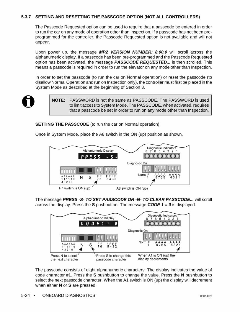
• ONBOARD DIAGNOSTICS 42-02-40225-24
NOTE: PASSWORD is not the same as PASSCODE. The PASSWORD is usedto limit access to System Mode. The PASSCODE, when activated, requiresthat a passcode be set in order to run on any mode other than Inspection.
5.3.7 SETTING AND RESETTING THE PASSCODE OPTION (NOT ALL CONTROLLERS)
The Passcode Requested option can be used to require that a passcode be entered in orderto run the car on any mode of operation other than Inspection. If a passcode has not been pre-programmed for the controller, the Passcode Requested option is not available and will notappear.
Upon power up, the message MP2 VERSION NUMBER: 8.00.0 will scroll across thealphanumeric display. If a passcode has been pre-programmed and the Passcode Requestedoption has been activated, the message PASSCODE REQUESTED... is then scrolled. Thismeans a passcode is required in order to run the elevator on any mode other than Inspection.
In order to set the passcode (to run the car on Normal operation) or reset the passcode (todisallow Normal Operation and run on Inspection only), the controller must first be placed in theSystem Mode as described at the beginning of Section 3.
SETTING THE PASSCODE (to run the car on Normal operation)
Once in System Mode, place the A8 switch in the ON (up) position as shown.
The message PRESS -S- TO SET PASSCODE OR -N- TO CLEAR PASSCODE... will scrollacross the display. Press the S pushbutton. The message CODE 1 = 0 is displayed.
The passcode consists of eight alphanumeric characters. The display indicates the value ofcode character #1. Press the S pushbutton to change the value. Press the N pushbutton toselect the next passcode character. When the A1 switch is ON (up) the display will decrementwhen either N or S are pressed.
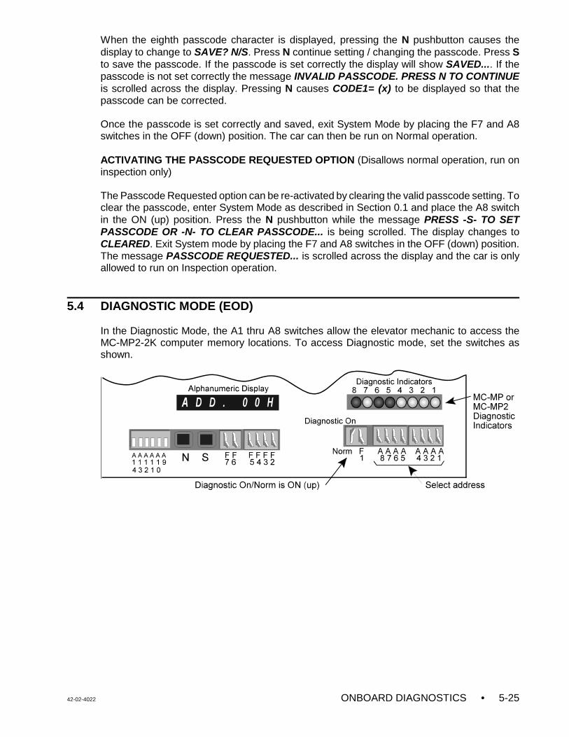
42-02-4022 ONBOARD DIAGNOSTICS • 5-25
When the eighth passcode character is displayed, pressing the N pushbutton causes thedisplay to change to SAVE? N/S. Press N continue setting / changing the passcode. Press Sto save the passcode. If the passcode is set correctly the display will show SAVED.... If thepasscode is not set correctly the message INVALID PASSCODE. PRESS N TO CONTINUEis scrolled across the display. Pressing N causes CODE1= (x) to be displayed so that thepasscode can be corrected.
Once the passcode is set correctly and saved, exit System Mode by placing the F7 and A8switches in the OFF (down) position. The car can then be run on Normal operation.
ACTIVATING THE PASSCODE REQUESTED OPTION (Disallows normal operation, run oninspection only)
The Passcode Requested option can be re-activated by clearing the valid passcode setting. Toclear the passcode, enter System Mode as described in Section 0.1 and place the A8 switchin the ON (up) position. Press the N pushbutton while the message PRESS -S- TO SETPASSCODE OR -N- TO CLEAR PASSCODE... is being scrolled. The display changes toCLEARED. Exit System mode by placing the F7 and A8 switches in the OFF (down) position.The message PASSCODE REQUESTED... is scrolled across the display and the car is onlyallowed to run on Inspection operation.
5.4 DIAGNOSTIC MODE (EOD)
In the Diagnostic Mode, the A1 thru A8 switches allow the elevator mechanic to access theMC-MP2-2K computer memory locations. To access Diagnostic mode, set the switches asshown.
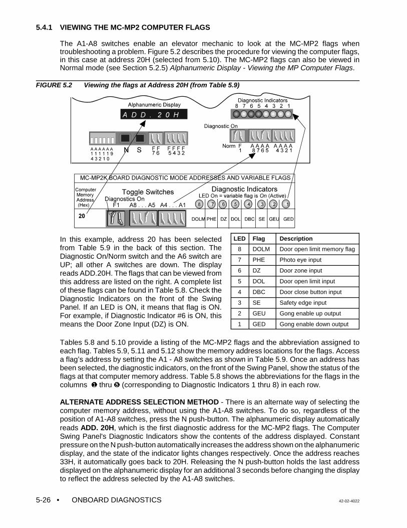
• ONBOARD DIAGNOSTICS 42-02-40225-26
5.4.1 VIEWING THE MC-MP2 COMPUTER FLAGS
The A1-A8 switches enable an elevator mechanic to look at the MC-MP2 flags whentroubleshooting a problem. Figure 5.2 describes the procedure for viewing the computer flags,in this case at address 20H (selected from 5.10). The MC-MP2 flags can also be viewed inNormal mode (see Section 5.2.5) Alphanumeric Display - Viewing the MP Computer Flags.
FIGURE 5.2 Viewing the flags at Address 20H (from Table 5.9)
In this example, address 20 has been selectedfrom Table 5.9 in the back of this section. TheDiagnostic On/Norm switch and the A6 switch areUP; all other A switches are down. The displayreads ADD.20H. The flags that can be viewed fromthis address are listed on the right. A complete listof these flags can be found in Table 5.8. Check theDiagnostic Indicators on the front of the SwingPanel. If an LED is ON, it means that flag is ON.For example, if Diagnostic Indicator #6 is ON, thismeans the Door Zone Input (DZ) is ON.
LED Flag Description
8 DOLM Door open limit memory flag
7 PHE Photo eye input
6 DZ Door zone input
5 DOL Door open limit input
4 DBC Door close button input
3 SE Safety edge input
2 GEU Gong enable up output
1 GED Gong enable down output
Tables 5.8 and 5.10 provide a listing of the MC-MP2 flags and the abbreviation assigned toeach flag. Tables 5.9, 5.11 and 5.12 show the memory address locations for the flags. Accessa flag’s address by setting the A1 - A8 switches as shown in Table 5.9. Once an address hasbeen selected, the diagnostic indicators, on the front of the Swing Panel, show the status of theflags at that computer memory address. Table 5.8 shows the abbreviations for the flags in thecolumns Ø thru ß (corresponding to Diagnostic Indicators 1 thru 8) in each row.
ALTERNATE ADDRESS SELECTION METHOD - There is an alternate way of selecting thecomputer memory address, without using the A1-A8 switches. To do so, regardless of theposition of A1-A8 switches, press the N push-button. The alphanumeric display automaticallyreads ADD. 20H, which is the first diagnostic address for the MC-MP2 flags. The ComputerSwing Panel's Diagnostic Indicators show the contents of the address displayed. Constantpressure on the N push-button automatically increases the address shown on the alphanumericdisplay, and the state of the indicator lights changes respectively. Once the address reaches33H, it automatically goes back to 20H. Releasing the N push-button holds the last addressdisplayed on the alphanumeric display for an additional 3 seconds before changing the displayto reflect the address selected by the A1-A8 switches.
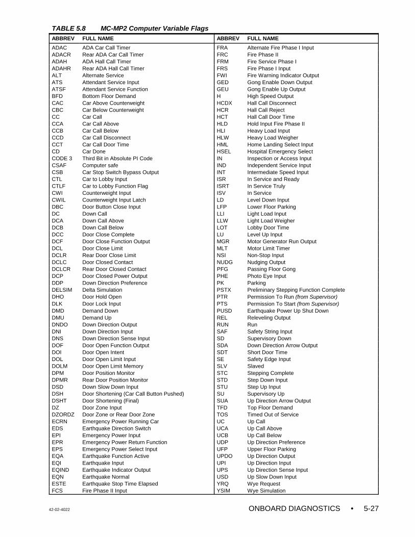
42-02-4022 ONBOARD DIAGNOSTICS • 5-27
TABLE 5.8 MC-MP2 Computer Variable FlagsABBREV FULL NAME ABBREV FULL NAME
ADAC ADA Car Call Timer FRA Alternate Fire Phase I InputADACR Rear ADA Car Call Timer FRC Fire Phase IIADAH ADA Hall Call Timer FRM Fire Service Phase I ADAHR Rear ADA Hall Call Timer FRS Fire Phase I InputALT Alternate Service FWI Fire Warning Indicator OutputATS Attendant Service Input GED Gong Enable Down OutputATSF Attendant Service Function GEU Gong Enable Up OutputBFD Bottom Floor Demand H High Speed OutputCAC Car Above Counterweight HCDX Hall Call Disconnect CBC Car Below Counterweight HCR Hall Call Reject CC Car Call HCT Hall Call Door Time CCA Car Call Above HLD Hold Input Fire Phase IICCB Car Call Below HLI Heavy Load InputCCD Car Call Disconnect HLW Heavy Load WeigherCCT Car Call Door Time HML Home Landing Select InputCD Car Done HSEL Hospital Emergency SelectCODE 3 Third Bit in Absolute PI Code IN Inspection or Access InputCSAF Computer safe IND Independent Service InputCSB Car Stop Switch Bypass Output INT Intermediate Speed InputCTL Car to Lobby Input ISR In Service and ReadyCTLF Car to Lobby Function Flag ISRT In Service Truly CWI Counterweight Input ISV In Service CWIL Counterweight Input Latch LD Level Down InputDBC Door Button Close Input LFP Lower Floor Parking DC Down Call LLI Light Load InputDCA Down Call Above LLW Light Load WeigherDCB Down Call Below LOT Lobby Door Time DCC Door Close Complete LU Level Up InputDCF Door Close Function Output MGR Motor Generator Run Output DCL Door Close Limit MLT Motor Limit Timer DCLR Rear Door Close Limit NSI Non-Stop InputDCLC Door Closed Contact NUDG Nudging OutputDCLCR Rear Door Closed Contact PFG Passing Floor GongDCP Door Closed Power Output PHE Photo Eye InputDDP Down Direction Preference PK Parking DELSIM Delta Simulation PSTX Preliminary Stepping Function CompleteDHO Door Hold Open PTR Permission To Run (from Supervisor)DLK Door Lock Input PTS Permission To Start (from Supervisor)DMD Demand Down PUSD Earthquake Power Up Shut DownDMU Demand Up REL Releveling OutputDNDO Down Direction Output RUN Run DNI Down Direction Input SAF Safety String InputDNS Down Direction Sense Input SD Supervisory Down DOF Door Open Function Output SDA Down Direction Arrow OutputDOI Door Open Intent SDT Short Door Time DOL Door Open Limit Input SE Safety Edge InputDOLM Door Open Limit Memory SLV Slaved DPM Door Position Monitor STC Stepping Complete DPMR Rear Door Position Monitor STD Step Down InputDSD Down Slow Down Input STU Step Up InputDSH Door Shortening (Car Call Button Pushed) SU Supervisory Up DSHT Door Shortening (Final) SUA Up Direction Arrow OutputDZ Door Zone Input TFD Top Floor DemandDZORDZ Door Zone or Rear Door Zone TOS Timed Out of Service ECRN Emergency Power Running Car UC Up Call EDS Earthquake Direction Switch UCA Up Call Above EPI Emergency Power Input UCB Up Call Below EPR Emergency Power Return Function UDP Up Direction PreferenceEPS Emergency Power Select Input UFP Upper Floor Parking EQA Earthquake Function Active UPDO Up Direction OutputEQI Earthquake Input UPI Up Direction InputEQIND Earthquake Indicator Output UPS Up Direction Sense InputEQN Earthquake Normal USD Up Slow Down InputESTE Earthquake Stop Time Elapsed YRQ Wye RequestFCS Fire Phase II Input YSIM Wye Simulation
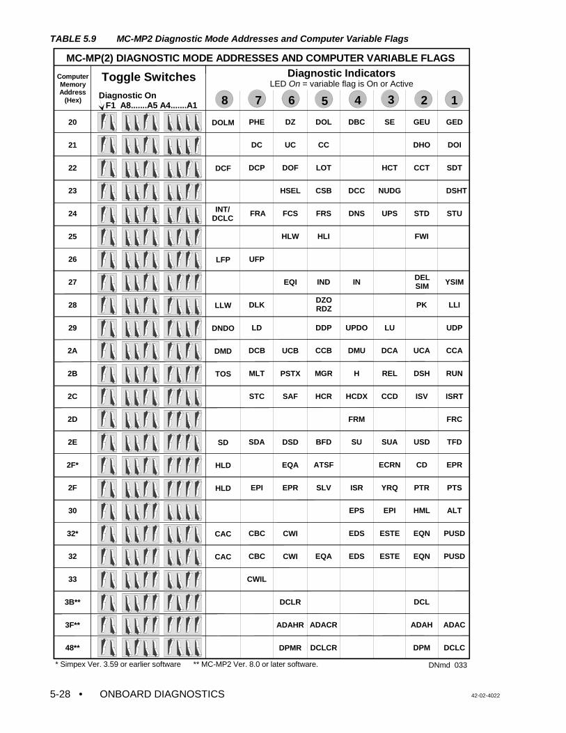
• ONBOARD DIAGNOSTICS 42-02-40225-28
GED
DOI
SDT
DSHT
STU
YSIM
LLI
UDP
CCA
RUN
ISRT
FRC
TFD
EPR
PTS
ALT
PUSD
PUSD
ADAC
DCLC
GEU
DHO
CCT
STD
FWI
PK
UCA
DSH
ISV
USD
CD
PTR
HML
EQN
EQN
DCL
ADAH
DPM
SE
HCT
NUDG
UPS
LU
DCA
REL
CCD
SUA
ECRN
YRQ
EPI
ESTE
ESTE
DBC
DCC
DNS
IN
UPDO
DMU
H
HCDX
FRM
SU
ISR
EPS
EDS
EDS
DOL
CC
LOT
CSB
FRS
HLI
IND
DDP
CCB
MGR
HCR
BFD
ATSF
SLV
EQA
ADACR
DCLCR
DZ
UC
DOF
HSEL
FCS
HLW
EQI
UCB
PSTX
SAF
DSD
EQA
EPR
CWI
CWI
DCLR
ADAHR
DPMR
PHE
DC
DCP
FRA
UFP
DLK
LD
DCB
MLT
STC
SDA
EPI
CBC
CBC
CWIL
DOLM
DCF
LFP
LLW
DNDO
DMD
TOS
SD
HLD
HLD
CAC
CAC
MC-MP(2) DIAGNOSTIC MODE ADDRESSES AND COMPUTER VARIABLE FLAGS
ComputerMemoryAddress
(Hex)Diagnostic On F1 A8.......A5 A4.......A1
20
21
22
23
24
25
26
27
28
29
2A
2B
2C
2D
2E
2F*
2F
30
32*
32
33
3B**
3F**
48**
* Simpex Ver. 3.59 or earlier software ** MC-MP2 Ver. 8.0 or later software.
Diagnostic IndicatorsLED On = variable flag is On or Active
8
Toggle Switches
INT/DCLC
DZORDZ
DELSIM
DNmd 033
1234567
TABLE 5.9 MC-MP2 Diagnostic Mode Addresses and Computer Variable Flags
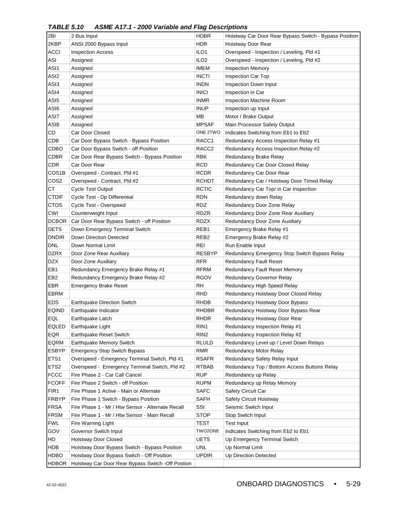
42-02-4022 ONBOARD DIAGNOSTICS • 5-29
TABLE 5.10 ASME A17.1 - 2000 Variable and Flag Descriptions2BI 2 Bus Input HDBR Hoistway Car Door Rear Bypass Switch - Bypass Position
2KBP ANSI 2000 Bypass Input HDR Hoistway Door Rear
ACCI Inspection Access ILO1 Overspeed - Inspection / Leveling, Pld #1
ASI Assigned ILO2 Overspeed - Inspection / Leveling, Pld #2
ASI1 Assigned IMEM Inspection Memory
ASI2 Assigned INCTI Inspection Car Top
ASI3 Assigned INDN Inspection Down Input
ASI4 Assigned INICI Inspection in Car
ASI5 Assigned INMR Inspection Machine Room
ASI6 Assigned INUP Inspection up Input
ASI7 Assigned MB Motor / Brake Output
ASI8 Assigned MPSAF Main Processor Safety Output
CD Car Door Closed ONE 2TWO Indicates Switching from Eb1 to Eb2
CDB Car Door Bypass Switch - Bypass Position RACC1 Redundancy Access Inspection Relay #1
CDBO Car Door Bypass Switch - off Position RACC2 Redundancy Access Inspection Relay #2
CDBR Car Door Rear Bypass Switch - Bypass Position RBK Redundancy Brake Relay
CDR Car Door Rear RCD Redundancy Car Door Closed Relay
COS1B Overspeed - Contract, Pld #1 RCDR Redundancy Car Door Rear
COS2 Overspeed - Contract, Pld #2 RCHDT Redundancy Car / Hoistway Door Timed Relay
CT Cycle Test Output RCTIC Redundancy Car Top/ in Car Inspection
CTDIF Cycle Test - Dp Differential RDN Redundancy down Relay
CTOS Cycle Test - Overspeed RDZ Redundancy Door Zone Relay
CWI Counterweight Input RDZR Redundancy Door Zone Rear Auxiliary
DCBOR Car Door Rear Bypass Switch - off Position RDZX Redundancy Door Zone Auxiliary
DETS Down Emergency Terminal Switch REB1 Emergency Brake Relay #1
DNDIR Down Direction Detected REB2 Emergency Brake Relay #2
DNL Down Normal Limit REI Run Enable Input
DZRX Door Zone Rear Auxiliary RESBYP Redundancy Emergency Stop Switch Bypass Relay
DZX Door Zone Auxiliary RFR Redundancy Fault Reset
EB1 Redundancy Emergency Brake Relay #1 RFRM Redundancy Fault Reset Memory
EB2 Redundancy Emergency Brake Relay #2 RGOV Redundancy Governor Relay
EBR Emergency Brake Reset RH Redundancy High Speed Relay
EBRM RHD Redundancy Hoistway Door Closed Relay
EDS Earthquake Direction Switch RHDB Redundancy Hoistway Door Bypass
EQIND Earthquake Indicator RHDBR Redundancy Hoistway Door Bypass Rear
EQL Earthquake Latch RHDR Redundancy Hoistway Door Rear
EQLED Earthquake Light RIN1 Redundancy Inspection Relay #1
EQR Earthquake Reset Switch RIN2 Redundancy Inspection Relay #2
EQRM Earthquake Memory Switch RLULD Redundancy Level up / Level Down Relays
ESBYP Emergency Stop Switch Bypass RMR Redundancy Motor Relay
ETS1 Overspeed - Emergency Terminal Switch, Pld #1 RSAFR Redundancy Safety Relay Input
ETS2 Overspeed - Emergency Terminal Switch, Pld #2 RTBAB Redundancy Top / Bottom Access Buttons Relay
FCCC Fire Phase 2 - Car Call Cancel RUP Redundancy up Relay
FCOFF Fire Phase 2 Switch - off Position RUPM Redundancy up Relay Memory
FIR1 Fire Phase 1 Active - Main or Alternate SAFC Safety Circuit Car
FRBYP Fire Phase 1 Switch - Bypass Position SAFH Safety Circuit Hoistway
FRSA Fire Phase 1 - Mr / Htw Sensor - Alternate Recall SSI Seismic Switch Input
FRSM Fire Phase 1 - Mr / Htw Sensor - Main Recall STOP Stop Switch Input
FWL Fire Warning Light TEST Test Input
GOV Governor Switch Input TWO2ONE Indicates Switching from Eb2 to Eb1
HD Hoistway Door Closed UETS Up Emergency Terminal Switch
HDB Hoistway Door Bypass Switch - Bypass Position UNL Up Normal Limit
HDBO Hoistway Door Bypass Switch - Off Position UPDIR Up Direction Detected
HDBOR Hoistway Car Door Rear Bypass Switch -Off Postion
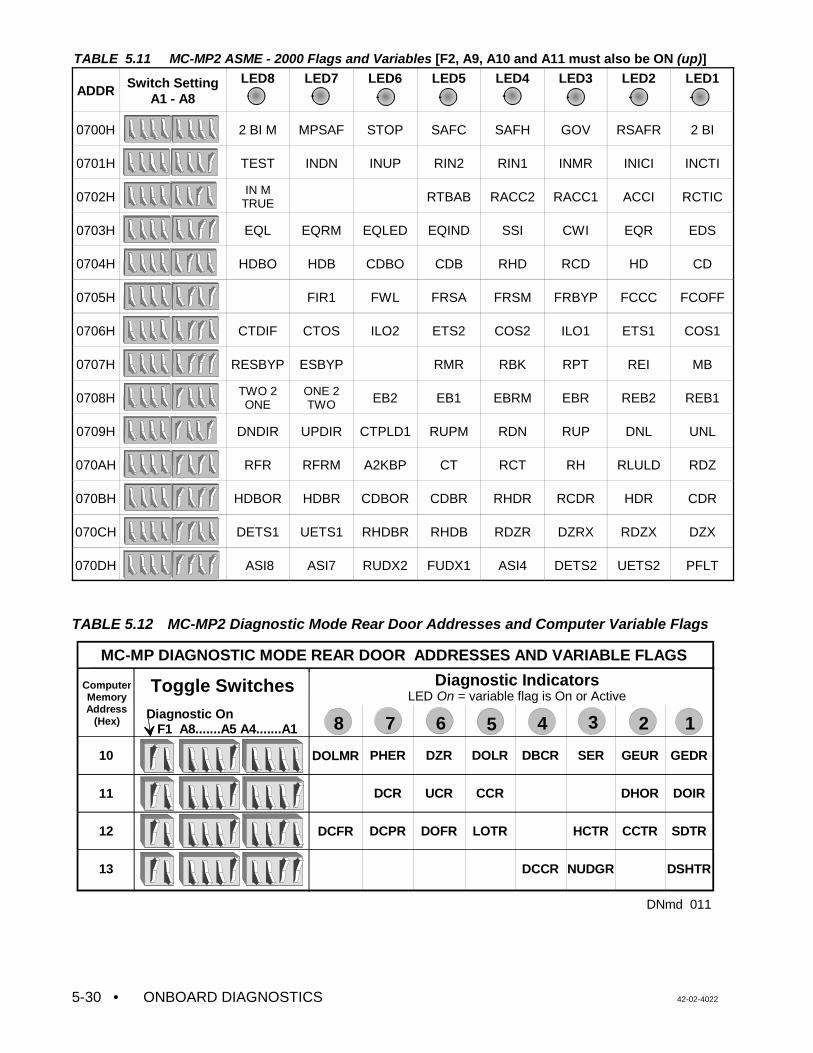
• ONBOARD DIAGNOSTICS 42-02-40225-30
GEDR
DOIR
SDTR
DSHTR
GEUR
DHOR
CCTR
SER
HCTR
NUDGR
DBCR
DCCR
DOLR
CCR
LOTR
DZR
UCR
DOFR
PHER
DCR
DCPR
DOLMR
DCFR
MC-MP DIAGNOSTIC MODE REAR DOOR ADDRESSES AND VARIABLE FLAGS
ComputerMemoryAddress
(Hex)Diagnostic On F1 A8.......A5 A4.......A1
10
11
12
13
Diagnostic IndicatorsLED On = variable flag is On or Active
Toggle Switches
DNmd 011
8 1234567
TABLE 5.11 MC-MP2 ASME - 2000 Flags and Variables [F2, A9, A10 and A11 must also be ON (up)]
ADDR Switch SettingA1 - A8
LED8 LED7 LED6 LED5 LED4 LED3 LED2 LED1
0700H 2 BI M MPSAF STOP SAFC SAFH GOV RSAFR 2 BI
0701H TEST INDN INUP RIN2 RIN1 INMR INICI INCTI
0702H IN MTRUE RTBAB RACC2 RACC1 ACCI RCTIC
0703H EQL EQRM EQLED EQIND SSI CWI EQR EDS
0704H HDBO HDB CDBO CDB RHD RCD HD CD
0705H FIR1 FWL FRSA FRSM FRBYP FCCC FCOFF
0706H CTDIF CTOS ILO2 ETS2 COS2 ILO1 ETS1 COS1
0707H RESBYP ESBYP RMR RBK RPT REI MB
0708H TWO 2ONE
ONE 2TWO EB2 EB1 EBRM EBR REB2 REB1
0709H DNDIR UPDIR CTPLD1 RUPM RDN RUP DNL UNL
070AH RFR RFRM A2KBP CT RCT RH RLULD RDZ
070BH HDBOR HDBR CDBOR CDBR RHDR RCDR HDR CDR
070CH DETS1 UETS1 RHDBR RHDB RDZR DZRX RDZX DZX
070DH ASI8 ASI7 RUDX2 FUDX1 ASI4 DETS2 UETS2 PFLT
TABLE 5.12 MC-MP2 Diagnostic Mode Rear Door Addresses and Computer Variable Flags
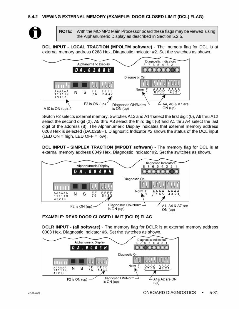
42-02-4022 ONBOARD DIAGNOSTICS • 5-31
NOTE: With the MC-MP2 Main Processor board these flags may be viewed usingthe Alphanumeric Display as described in Section 5.2.5.
5.4.2 VIEWING EXTERNAL MEMORY (EXAMPLE: DOOR CLOSED LIMIT (DCL) FLAG)
DCL INPUT - LOCAL TRACTION (MPOLTM software) - The memory flag for DCL is atexternal memory address 0268 Hex, Diagnostic Indicator #2. Set the switches as shown.
Switch F2 selects external memory. Switches A13 and A14 select the first digit (0), A9 thru A12select the second digit (2), A5 thru A8 select the third digit (6) and A1 thru A4 select the lastdigit of the address (8). The Alphanumeric Display indicates that external memory address0268 Hex is selected (DA.0268H). Diagnostic Indicator #2 shows the status of the DCL input(LED ON = high, LED OFF = low).
DCL INPUT - SIMPLEX TRACTION (MPODT software) - The memory flag for DCL is atexternal memory address 0049 Hex, Diagnostic Indicator #2. Set the switches as shown.
EXAMPLE: REAR DOOR CLOSED LIMIT (DCLR) FLAG
DCLR INPUT - (all software) - The memory flag for DCLR is at external memory address0003 Hex, Diagnostic Indicator #6. Set the switches as shown.
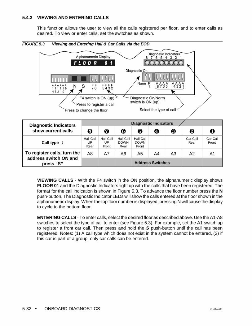
• ONBOARD DIAGNOSTICS 42-02-40225-32
5.4.3 VIEWING AND ENTERING CALLS
This function allows the user to view all the calls registered per floor, and to enter calls asdesired. To view or enter calls, set the switches as shown.
FIGURE 5.3 Viewing and Entering Hall & Car Calls via the EOD
Diagnostic Indicatorsshow current calls
Diagnostic Indicators
ß Þ Ý Ü Û Ú Ù Ø
Call type ,Hall Call
UPRear
Hall CallUP
Front
Hall CallDOWNRear
Hall CallDOWNFront
Car CallRear
Car CallFront
To register calls, turn theaddress switch ON and
press “S”
A8 A7 A6 A5 A4 A3 A2 A1
Address Switches
VIEWING CALLS - With the F4 switch in the ON position, the alphanumeric display showsFLOOR 01 and the Diagnostic Indicators light up with the calls that have been registered. Theformat for the call indication is shown in Figure 5.3. To advance the floor number press the Npush-button. The Diagnostic Indicator LEDs will show the calls entered at the floor shown in thealphanumeric display. When the top floor number is displayed, pressing N will cause the displayto cycle to the bottom floor.
ENTERING CALLS - To enter calls, select the desired floor as described above. Use the A1-A8switches to select the type of call to enter (see Figure 5.3). For example, set the A1 switch upto register a front car call. Then press and hold the S push-button until the call has beenregistered. Notes: (1) A call type which does not exist in the system cannot be entered, (2) ifthis car is part of a group, only car calls can be entered.
42-02-4022 TROUBLESHOOTING • 6-1
SECTION 6TROUBLESHOOTING
6.0 GENERAL INFORMATION
VVMC-1000-Series M controllers are equipped with certain features that can help speed uptroubleshooting. Often the controller will indicate the nature of the problem in the form of astatus or error message scrolling on the Computer Swing Panel's display. The optional CRTterminal connected to either the car controller or the Group Supervisor can provide usefuldiagnostics in the form of View Hoistway (F3 screen) messages and/or Special EventsCalendar Fault Log (F7, 1 screen) messages. Tables 6.3 and 6.4 provide a complete listingof these messages, a description and recommended corrective actions to be taken.
Troubleshooting often involves determining the status of specific inputs, outputs or computervariable flags. This information is stored in the controller's memory and the status of thesememory locations can be viewed using the Computer Swing Panel's Enhanced OnboardDiagnostics (EOD), described in Section 5. In addition, the system is designed so that tracingsignals from the field wires onto various boards and into the computer can be achieved withoutthe need for mechanical removal of any components or for rear access to the boards.
The troubleshooting section is arranged as follows:
Troubleshooting Topic: Go to:
Status and Error Messages table and look-up table for the MC-MP2-2KDiagnostic Indicator and F3 screen messages.
Section 6.1
How to use the Special Events Calendar and setup for reportingemergency messages to a PC running CMS software.
Section 6.2
Using the Controller Diagnostics screens Section 6.3
Troubleshooting Car Operation Control (COC), Door Logic, Call Logic,and Quick References for the HC-PI/O and HC-CI/O boards.
Section 6.4
PC Board Quick References Section 6.5
Troubleshooting the MagneTek DSD 412 SCR Drive Section 6.6
Troubleshooting Using the DSD412 Control Display Unit Section 6.7
DSD412 Drive Troubleshooting Flowcharts Section 6.8
ASME A17.1 - 2000 Fault Troubleshooting Tables Section 6.9
Using the MLT Data Trap Section 6.10
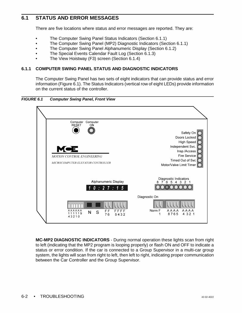
• TROUBLESHOOTING 42-02-40226-2
6.1 STATUS AND ERROR MESSAGES
There are five locations where status and error messages are reported. They are:
• The Computer Swing Panel Status Indicators (Section 6.1.1)• The Computer Swing Panel (MP2) Diagnostic Indicators (Section 6.1.1)• The Computer Swing Panel Alphanumeric Display (Section 6.1.2)• The Special Events Calendar Fault Log (Section 6.1.3)• The View Hoistway (F3) screen (Section 6.1.4)
6.1.1 COMPUTER SWING PANEL STATUS AND DIAGNOSTIC INDICATORS
The Computer Swing Panel has two sets of eight indicators that can provide status and errorinformation (Figure 6.1). The Status Indicators (vertical row of eight LEDs) provide informationon the current status of the controller.
FIGURE 6.1 Computer Swing Panel, Front View
MC-MP2 DIAGNOSTIC INDICATORS - During normal operation these lights scan from rightto left (indicating that the MP2 program is looping properly) or flash ON and OFF to indicate astatus or error condition. If the car is connected to a Group Supervisor in a multi-car groupsystem, the lights will scan from right to left, then left to right, indicating proper communicationbetween the Car Controller and the Group Supervisor.
42-02-4022 TROUBLESHOOTING • 6-3
NOTE: There are two ways to access detailed information about the scrollingStatus and Error messages:
• Look for the message in the Index to find the page on which themessage description and troubleshooting information is located.
• Refer to Table 6.1, MC-MP2 Scrolling Messages Lookup to find themessage being scrolled on the Alphanumeric Display. Then look for themessage by the Event Message name in Table 6.3 Status and ErrorMessages. Look for messages not found in Table 6.1 in Table 6.4ASME A17.1 - 2000 Status and Error Messages.
When a status or error condition exists, the Diagnostic Indicators flash one of severalmessages depending on the software version (MP2 version number scrolls on boot up):
• Software versions 8.02.00 or earlier flash theMC-MP-1ES messages.
• Software version 8.03.00 flashes CC Hex.
• Software versions 8.04.00 or later flash 66 Hex. Setthe alphanumeric display to scroll the status or errormessage. Refer to Table 6.3 Status and Error Messages for a description andtroubleshooting information for the scrolling message.
• ASME A17.1 - 2000 status and error conditions areindicated by the diagnostic indicators flashing 55 Hex. Setthe alphanumeric display to scroll the status or errormessage. Refer to Table 6.4 ASME A17.1 - 2000 Status andError Messages for a description and troubleshootinginformation for the scrolling message.
If the scrolling status or error message is not displayed on the Alphanumeric Display when theDiagnostic Indicators flash, press the N pushbutton until the scrolling message appears (seeSection 5.2.1 ALPHANUMERIC DISPLAY - STATUS AND ERROR MESSAGES).
6.1.2 ALPHANUMERIC DISPLAY - STATUS AND ERROR MESSAGES
Status and error messages are scrolled across the alphanumeric display. Table 6.1 providesa list of standard status and error messages and their associated Special Event Messagenames. A description and troubleshooting information for the scrolling message is listed inTable 6.3 under the Special Event Message name. Table 6.4 provides a list of ASMEA17.1-2000 status and error messages, including descriptions and troubleshooting information.
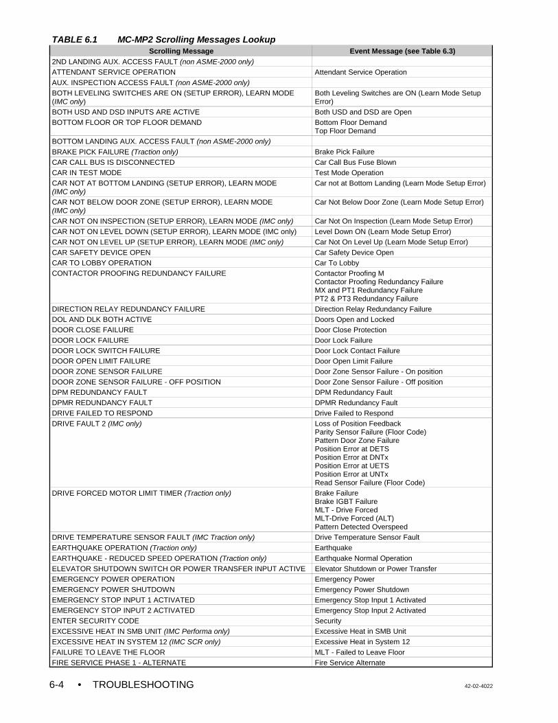
• TROUBLESHOOTING 42-02-40226-4
TABLE 6.1 MC-MP2 Scrolling Messages LookupScrolling Message Event Message (see Table 6.3)
2ND LANDING AUX. ACCESS FAULT (non ASME-2000 only) ATTENDANT SERVICE OPERATION Attendant Service OperationAUX. INSPECTION ACCESS FAULT (non ASME-2000 only)BOTH LEVELING SWITCHES ARE ON (SETUP ERROR), LEARN MODE (IMC only)
Both Leveling Switches are ON (Learn Mode SetupError)
BOTH USD AND DSD INPUTS ARE ACTIVE Both USD and DSD are OpenBOTTOM FLOOR OR TOP FLOOR DEMAND Bottom Floor Demand
Top Floor DemandBOTTOM LANDING AUX. ACCESS FAULT (non ASME-2000 only)BRAKE PICK FAILURE (Traction only) Brake Pick FailureCAR CALL BUS IS DISCONNECTED Car Call Bus Fuse BlownCAR IN TEST MODE Test Mode OperationCAR NOT AT BOTTOM LANDING (SETUP ERROR), LEARN MODE (IMC only)
Car not at Bottom Landing (Learn Mode Setup Error)
CAR NOT BELOW DOOR ZONE (SETUP ERROR), LEARN MODE (IMC only)
Car Not Below Door Zone (Learn Mode Setup Error)
CAR NOT ON INSPECTION (SETUP ERROR), LEARN MODE (IMC only) Car Not On Inspection (Learn Mode Setup Error)CAR NOT ON LEVEL DOWN (SETUP ERROR), LEARN MODE (IMC only) Level Down ON (Learn Mode Setup Error)CAR NOT ON LEVEL UP (SETUP ERROR), LEARN MODE (IMC only) Car Not On Level Up (Learn Mode Setup Error)CAR SAFETY DEVICE OPEN Car Safety Device OpenCAR TO LOBBY OPERATION Car To LobbyCONTACTOR PROOFING REDUNDANCY FAILURE Contactor Proofing M
Contactor Proofing Redundancy FailureMX and PT1 Redundancy FailurePT2 & PT3 Redundancy Failure
DIRECTION RELAY REDUNDANCY FAILURE Direction Relay Redundancy FailureDOL AND DLK BOTH ACTIVE Doors Open and LockedDOOR CLOSE FAILURE Door Close ProtectionDOOR LOCK FAILURE Door Lock FailureDOOR LOCK SWITCH FAILURE Door Lock Contact FailureDOOR OPEN LIMIT FAILURE Door Open Limit FailureDOOR ZONE SENSOR FAILURE Door Zone Sensor Failure - On positionDOOR ZONE SENSOR FAILURE - OFF POSITION Door Zone Sensor Failure - Off positionDPM REDUNDANCY FAULT DPM Redundancy FaultDPMR REDUNDANCY FAULT DPMR Redundancy FaultDRIVE FAILED TO RESPOND Drive Failed to RespondDRIVE FAULT 2 (IMC only) Loss of Position Feedback
Parity Sensor Failure (Floor Code)Pattern Door Zone FailurePosition Error at DETSPosition Error at DNTxPosition Error at UETSPosition Error at UNTxRead Sensor Failure (Floor Code)
DRIVE FORCED MOTOR LIMIT TIMER (Traction only) Brake FailureBrake IGBT FailureMLT - Drive ForcedMLT-Drive Forced (ALT)Pattern Detected Overspeed
DRIVE TEMPERATURE SENSOR FAULT (IMC Traction only) Drive Temperature Sensor Fault
EARTHQUAKE OPERATION (Traction only) Earthquake
EARTHQUAKE - REDUCED SPEED OPERATION (Traction only) Earthquake Normal OperationELEVATOR SHUTDOWN SWITCH OR POWER TRANSFER INPUT ACTIVE Elevator Shutdown or Power TransferEMERGENCY POWER OPERATION Emergency PowerEMERGENCY POWER SHUTDOWN Emergency Power ShutdownEMERGENCY STOP INPUT 1 ACTIVATED Emergency Stop Input 1 ActivatedEMERGENCY STOP INPUT 2 ACTIVATED Emergency Stop Input 2 ActivatedENTER SECURITY CODE SecurityEXCESSIVE HEAT IN SMB UNIT (IMC Performa only) Excessive Heat in SMB Unit
EXCESSIVE HEAT IN SYSTEM 12 (IMC SCR only) Excessive Heat in System 12FAILURE TO LEAVE THE FLOOR MLT - Failed to Leave FloorFIRE SERVICE PHASE 1 - ALTERNATE Fire Service Alternate
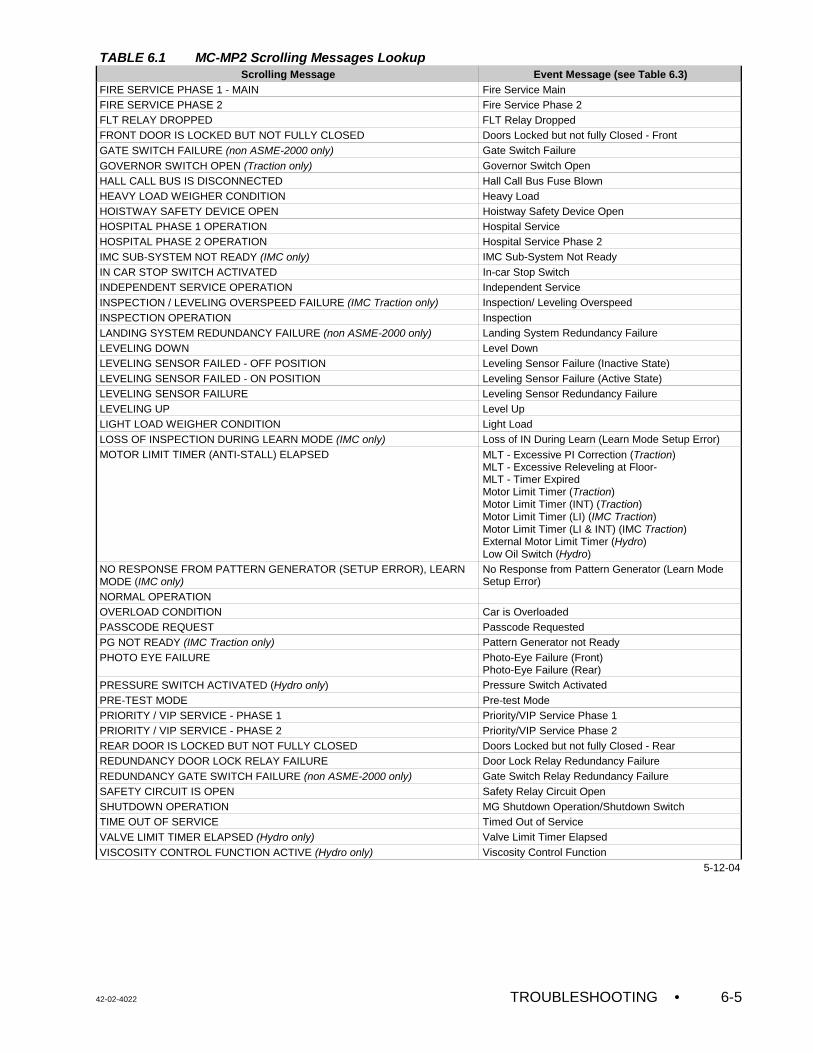
TABLE 6.1 MC-MP2 Scrolling Messages LookupScrolling Message Event Message (see Table 6.3)
42-02-4022 TROUBLESHOOTING • 6-5
FIRE SERVICE PHASE 1 - MAIN Fire Service MainFIRE SERVICE PHASE 2 Fire Service Phase 2FLT RELAY DROPPED FLT Relay DroppedFRONT DOOR IS LOCKED BUT NOT FULLY CLOSED Doors Locked but not fully Closed - FrontGATE SWITCH FAILURE (non ASME-2000 only) Gate Switch Failure
GOVERNOR SWITCH OPEN (Traction only) Governor Switch OpenHALL CALL BUS IS DISCONNECTED Hall Call Bus Fuse BlownHEAVY LOAD WEIGHER CONDITION Heavy LoadHOISTWAY SAFETY DEVICE OPEN Hoistway Safety Device OpenHOSPITAL PHASE 1 OPERATION Hospital ServiceHOSPITAL PHASE 2 OPERATION Hospital Service Phase 2IMC SUB-SYSTEM NOT READY (IMC only) IMC Sub-System Not ReadyIN CAR STOP SWITCH ACTIVATED In-car Stop SwitchINDEPENDENT SERVICE OPERATION Independent ServiceINSPECTION / LEVELING OVERSPEED FAILURE (IMC Traction only) Inspection/ Leveling OverspeedINSPECTION OPERATION InspectionLANDING SYSTEM REDUNDANCY FAILURE (non ASME-2000 only) Landing System Redundancy FailureLEVELING DOWN Level DownLEVELING SENSOR FAILED - OFF POSITION Leveling Sensor Failure (Inactive State)LEVELING SENSOR FAILED - ON POSITION Leveling Sensor Failure (Active State)LEVELING SENSOR FAILURE Leveling Sensor Redundancy FailureLEVELING UP Level UpLIGHT LOAD WEIGHER CONDITION Light LoadLOSS OF INSPECTION DURING LEARN MODE (IMC only) Loss of IN During Learn (Learn Mode Setup Error)MOTOR LIMIT TIMER (ANTI-STALL) ELAPSED MLT - Excessive PI Correction (Traction)
MLT - Excessive Releveling at Floor- MLT - Timer ExpiredMotor Limit Timer (Traction)Motor Limit Timer (INT) (Traction)Motor Limit Timer (LI) (IMC Traction)Motor Limit Timer (LI & INT) (IMC Traction)External Motor Limit Timer (Hydro)Low Oil Switch (Hydro)
NO RESPONSE FROM PATTERN GENERATOR (SETUP ERROR), LEARNMODE (IMC only)
No Response from Pattern Generator (Learn ModeSetup Error)
NORMAL OPERATIONOVERLOAD CONDITION Car is OverloadedPASSCODE REQUEST Passcode RequestedPG NOT READY (IMC Traction only) Pattern Generator not ReadyPHOTO EYE FAILURE Photo-Eye Failure (Front)
Photo-Eye Failure (Rear)PRESSURE SWITCH ACTIVATED (Hydro only) Pressure Switch ActivatedPRE-TEST MODE Pre-test ModePRIORITY / VIP SERVICE - PHASE 1 Priority/VIP Service Phase 1PRIORITY / VIP SERVICE - PHASE 2 Priority/VIP Service Phase 2REAR DOOR IS LOCKED BUT NOT FULLY CLOSED Doors Locked but not fully Closed - RearREDUNDANCY DOOR LOCK RELAY FAILURE Door Lock Relay Redundancy FailureREDUNDANCY GATE SWITCH FAILURE (non ASME-2000 only) Gate Switch Relay Redundancy FailureSAFETY CIRCUIT IS OPEN Safety Relay Circuit OpenSHUTDOWN OPERATION MG Shutdown Operation/Shutdown SwitchTIME OUT OF SERVICE Timed Out of ServiceVALVE LIMIT TIMER ELAPSED (Hydro only) Valve Limit Timer Elapsed
VISCOSITY CONTROL FUNCTION ACTIVE (Hydro only) Viscosity Control Function5-12-04
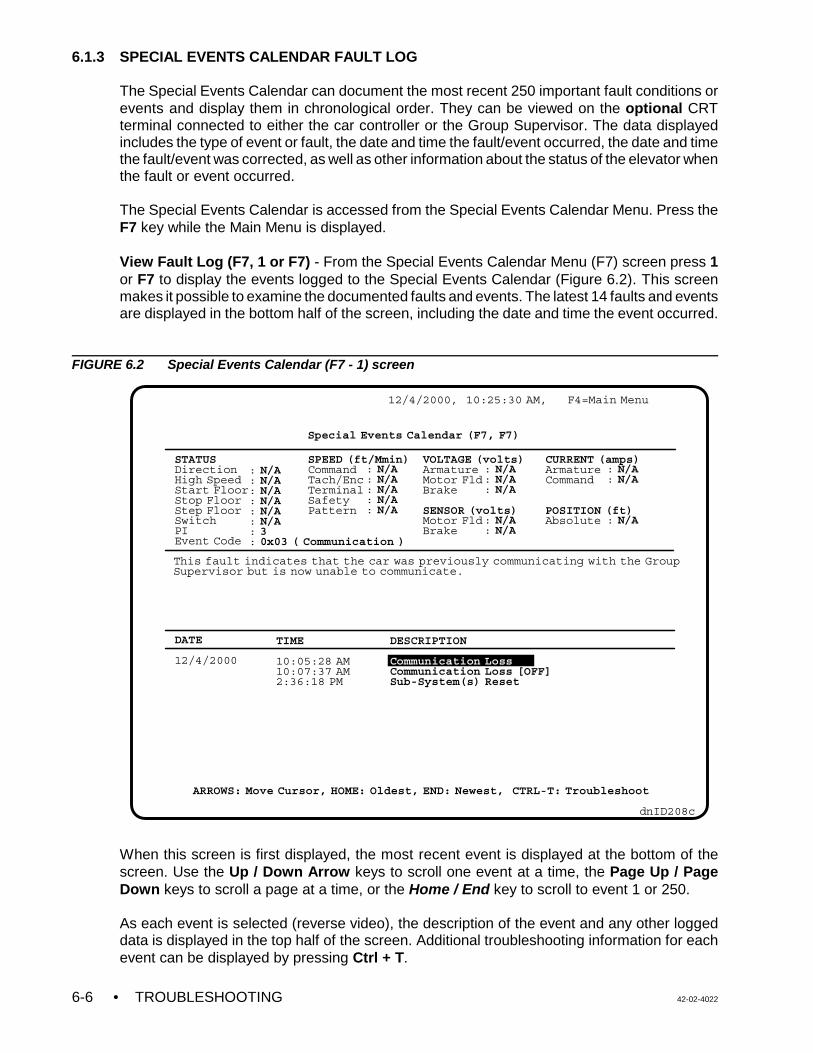
• TROUBLESHOOTING 42-02-40226-6
DESCRIPTION
Communication LossCommunication Loss [OFF]Sub-System(s) Reset
: N/A: N/A: N/A: N/A: N/A: N/A: 3: 0x03 ( Communication )
12/4/2000, 10:25:30 AM, F4=Main Menu
dnID208c
Special Events Calendar (F7, F7)
ARROWS: Move Cursor, HOME: Oldest, END: Newest, CTRL-T: Troubleshoot
STATUSDirectionHigh SpeedStart FloorStop FloorStep FloorSwitchPIEvent Code
DATE
12/4/2000
TIME
10:05:28 AM10:07:37 AM2:36:18 PM
SPEED (ft/Mmin)CommandTach/EncTerminalSafetyPattern
VOLTAGE (volts)ArmatureMotor FldBrake
SENSOR (volts)Motor FldBrake
CURRENT (amps)ArmatureCommand
POSITION (ft)Absolute
: N/A: N/A: N/A: N/A: N/A
: N/A: N/A: N/A
: N/A: N/A
: N/A: N/A
: N/A
This fault indicates that the car was previously communicating with the GroupSupervisor but is now unable to communicate.
6.1.3 SPECIAL EVENTS CALENDAR FAULT LOG
The Special Events Calendar can document the most recent 250 important fault conditions orevents and display them in chronological order. They can be viewed on the optional CRTterminal connected to either the car controller or the Group Supervisor. The data displayedincludes the type of event or fault, the date and time the fault/event occurred, the date and timethe fault/event was corrected, as well as other information about the status of the elevator whenthe fault or event occurred.
The Special Events Calendar is accessed from the Special Events Calendar Menu. Press theF7 key while the Main Menu is displayed.
View Fault Log (F7, 1 or F7) - From the Special Events Calendar Menu (F7) screen press 1or F7 to display the events logged to the Special Events Calendar (Figure 6.2). This screenmakes it possible to examine the documented faults and events. The latest 14 faults and eventsare displayed in the bottom half of the screen, including the date and time the event occurred.
FIGURE 6.2 Special Events Calendar (F7 - 1) screen
When this screen is first displayed, the most recent event is displayed at the bottom of thescreen. Use the Up / Down Arrow keys to scroll one event at a time, the Page Up / PageDown keys to scroll a page at a time, or the Home / End key to scroll to event 1 or 250.
As each event is selected (reverse video), the description of the event and any other loggeddata is displayed in the top half of the screen. Additional troubleshooting information for eachevent can be displayed by pressing Ctrl + T.
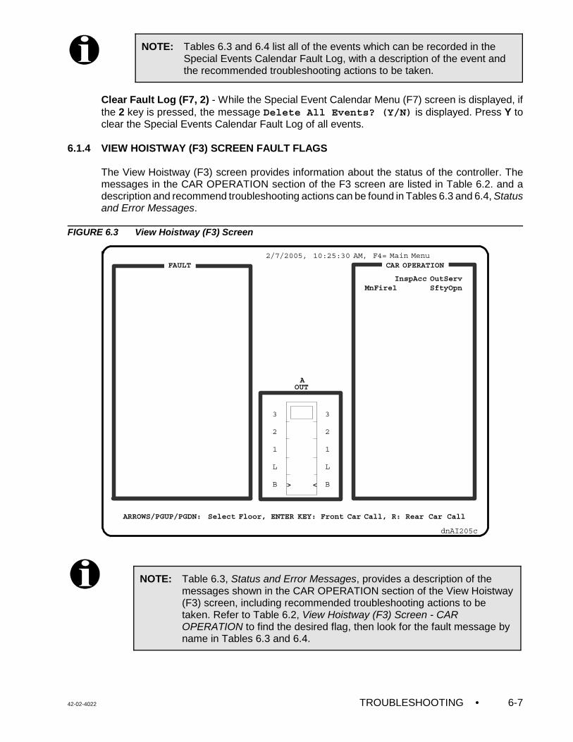
42-02-4022 TROUBLESHOOTING • 6-7
NOTE: Tables 6.3 and 6.4 list all of the events which can be recorded in theSpecial Events Calendar Fault Log, with a description of the event andthe recommended troubleshooting actions to be taken.
NOTE: Table 6.3, Status and Error Messages, provides a description of themessages shown in the CAR OPERATION section of the View Hoistway(F3) screen, including recommended troubleshooting actions to betaken. Refer to Table 6.2, View Hoistway (F3) Screen - CAROPERATION to find the desired flag, then look for the fault message byname in Tables 6.3 and 6.4.
2/7/2005, 10:25:30 AM, F4= Main Menu
dnAI205c
3
2
1
L
B
3
2
1
L
B> <
CAR OPERATIONFAULT
InspAcc OutServMnFire1 SftyOpn
AOUT
ARROWS/PGUP/PGDN: Select Floor, ENTER KEY: Front Car Call, R: Rear Car Call
Clear Fault Log (F7, 2) - While the Special Event Calendar Menu (F7) screen is displayed, ifthe 2 key is pressed, the message Delete All Events? (Y/N) is displayed. Press Y toclear the Special Events Calendar Fault Log of all events.
6.1.4 VIEW HOISTWAY (F3) SCREEN FAULT FLAGS
The View Hoistway (F3) screen provides information about the status of the controller. Themessages in the CAR OPERATION section of the F3 screen are listed in Table 6.2. and adescription and recommend troubleshooting actions can be found in Tables 6.3 and 6.4, Statusand Error Messages.
FIGURE 6.3 View Hoistway (F3) Screen
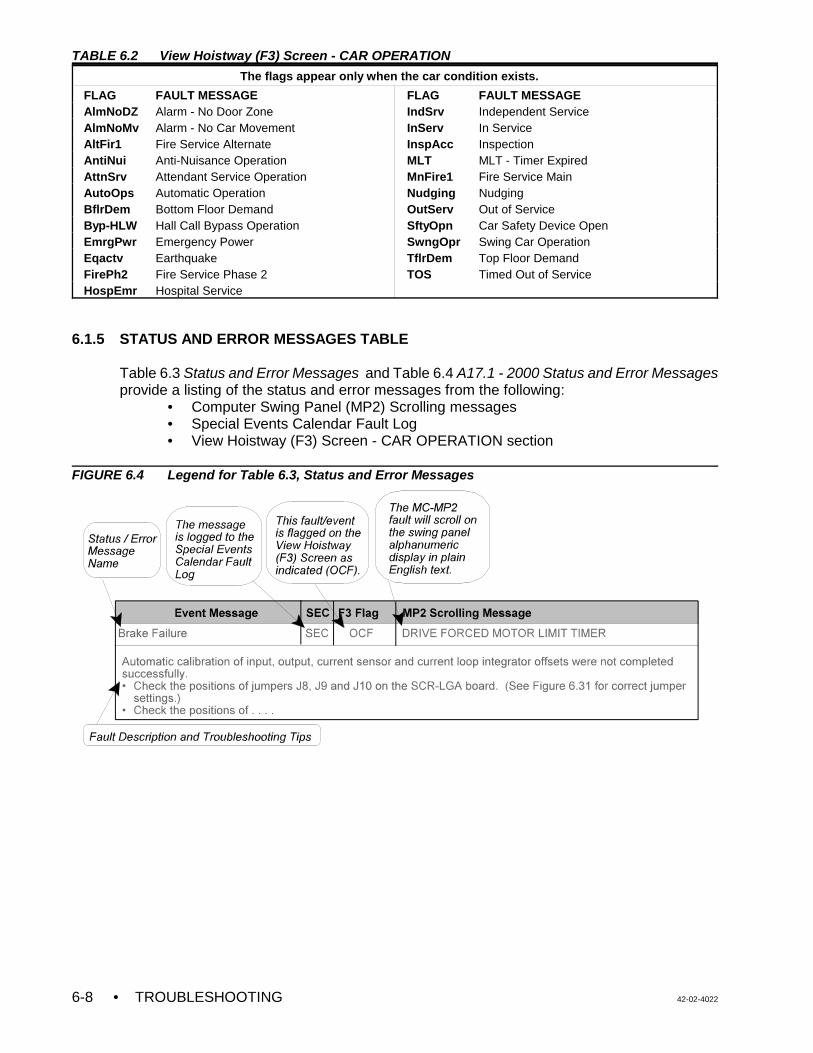
• TROUBLESHOOTING 42-02-40226-8
TABLE 6.2 View Hoistway (F3) Screen - CAR OPERATION
The flags appear only when the car condition exists.
FLAG FAULT MESSAGE FLAG FAULT MESSAGEAlmNoDZ Alarm - No Door Zone IndSrv Independent ServiceAlmNoMv Alarm - No Car Movement InServ In ServiceAltFir1 Fire Service Alternate InspAcc InspectionAntiNui Anti-Nuisance Operation MLT MLT - Timer ExpiredAttnSrv Attendant Service Operation MnFire1 Fire Service MainAutoOps Automatic Operation Nudging NudgingBflrDem Bottom Floor Demand OutServ Out of ServiceByp-HLW Hall Call Bypass Operation SftyOpn Car Safety Device OpenEmrgPwr Emergency Power SwngOpr Swing Car OperationEqactv Earthquake TflrDem Top Floor DemandFirePh2 Fire Service Phase 2 TOS Timed Out of ServiceHospEmr Hospital Service
6.1.5 STATUS AND ERROR MESSAGES TABLE
Table 6.3 Status and Error Messages and Table 6.4 A17.1 - 2000 Status and Error Messagesprovide a listing of the status and error messages from the following:
• Computer Swing Panel (MP2) Scrolling messages• Special Events Calendar Fault Log• View Hoistway (F3) Screen - CAR OPERATION section
FIGURE 6.4 Legend for Table 6.3, Status and Error Messages
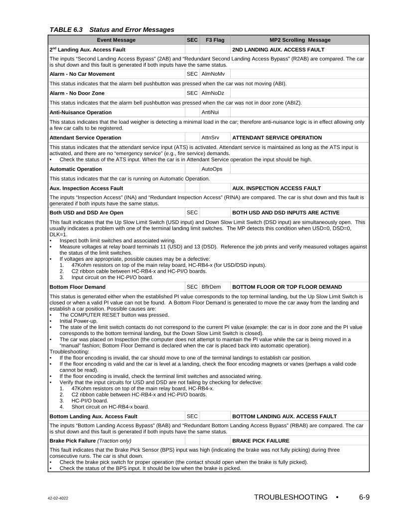
42-02-4022 TROUBLESHOOTING • 6-9
TABLE 6.3 Status and Error Messages
Event Message SEC F3 Flag MP2 Scrolling Message
2nd Landing Aux. Access Fault 2ND LANDING AUX. ACCESS FAULT
The inputs “Second Landing Access Bypass” (2AB) and “Redundant Second Landing Access Bypass” (R2AB) are compared. The caris shut down and this fault is generated if both inputs have the same status.
Alarm - No Car Movement SEC AlmNoMv
This status indicates that the alarm bell pushbutton was pressed when the car was not moving (ABI).
Alarm - No Door Zone SEC AlmNoDz
This status indicates that the alarm bell pushbutton was pressed when the car was not in door zone (ABIZ).
Anti-Nuisance Operation AntiNui
This status indicates that the load weigher is detecting a minimal load in the car; therefore anti-nuisance logic is in effect allowing onlya few car calls to be registered.
Attendant Service Operation AttnSrv ATTENDANT SERVICE OPERATION
This status indicates that the attendant service input (ATS) is activated. Attendant service is maintained as long as the ATS input isactivated, and there are no “emergency service” (e.g., fire service) demands. • Check the status of the ATS input. When the car is in Attendant Service operation the input should be high.
Automatic Operation AutoOps
This status indicates that the car is running on Automatic Operation.
Aux. Inspection Access Fault AUX. INSPECTION ACCESS FAULT
The inputs “Inspection Access” (INA) and “Redundant Inspection Access” (RINA) are compared. The car is shut down and this fault isgenerated if both inputs have the same status.
Both USD and DSD Are Open SEC BOTH USD AND DSD INPUTS ARE ACTIVE
This fault indicates that the Up Slow Limit Switch (USD input) and Down Slow Limit Switch (DSD input) are simultaneously open. Thisusually indicates a problem with one of the terminal landing limit switches. The MP detects this condition when USD=0, DSD=0,DLK=1.• Inspect both limit switches and associated wiring. • Measure voltages at relay board terminals 11 (USD) and 13 (DSD). Reference the job prints and verify measured voltages against
the status of the limit switches. • If voltages are appropriate, possible causes may be a defective:
1. 47Kohm resistors on top of the main relay board, HC-RB4-x (for USD/DSD inputs).2. C2 ribbon cable between HC-RB4-x and HC-PI/O boards.3. Input circuit on the HC-PI/O board.
Bottom Floor Demand SEC BflrDem BOTTOM FLOOR OR TOP FLOOR DEMAND
This status is generated either when the established PI value corresponds to the top terminal landing, but the Up Slow Limit Switch isclosed or when a valid PI value can not be found. A Bottom Floor Demand is generated to move the car away from the landing andestablish a car position. Possible causes are:• The COMPUTER RESET button was pressed.• Initial Power-up.• The state of the limit switch contacts do not correspond to the current PI value (example: the car is in door zone and the PI value
corresponds to the bottom terminal landing, but the Down Slow Limit Switch is closed).• The car was placed on Inspection (the computer does not attempt to maintain the PI value while the car is being moved in a
“manual” fashion; Bottom Floor Demand is declared when the car is placed back into automatic operation).Troubleshooting:• If the floor encoding is invalid, the car should move to one of the terminal landings to establish car position. • If the floor encoding is valid and the car is level at a landing, check the floor encoding magnets or vanes (perhaps a valid code
cannot be read).• If the floor encoding is invalid, check the terminal limit switches and associated wiring. • Verify that the input circuits for USD and DSD are not failing by checking for defective:
1. 47Kohm resistors on top of the main relay board, HC-RB4-x. 2. C2 ribbon cable between HC-RB4-x and HC-PI/O boards.3. HC-PI/O board.4. Short circuit on HC-RB4-x board.
Bottom Landing Aux. Access Fault SEC BOTTOM LANDING AUX. ACCESS FAULT
The inputs “Bottom Landing Access Bypass” (BAB) and “Redundant Bottom Landing Access Bypass” (RBAB) are compared. The caris shut down and this fault is generated if both inputs have the same status.
Brake Pick Failure (Traction only) BRAKE PICK FAILURE
This fault indicates that the Brake Pick Sensor (BPS) input was high (indicating the brake was not fully picking) during threeconsecutive runs. The car is shut down.• Check the brake pick switch for proper operation (the contact should open when the brake is fully picked). • Check the status of the BPS input. It should be low when the brake is picked.
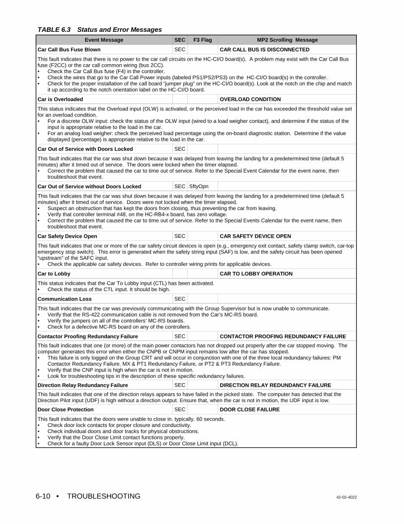
TABLE 6.3 Status and Error Messages
Event Message SEC F3 Flag MP2 Scrolling Message
• TROUBLESHOOTING 42-02-40226-10
Car Call Bus Fuse Blown SEC CAR CALL BUS IS DISCONNECTED
This fault indicates that there is no power to the car call circuits on the HC-CI/O board(s). A problem may exist with the Car Call Busfuse (F2CC) or the car call common wiring (bus 2CC).• Check the Car Call Bus fuse (F4) in the controller. • Check the wires that go to the Car Call Power inputs (labeled PS1/PS2/PS3) on the HC-CI/O board(s) in the controller. • Check for the proper installation of the call board “jumper plug” on the HC-CI/O board(s). Look at the notch on the chip and match
it up according to the notch orientation label on the HC-CI/O board.
Car is Overloaded OVERLOAD CONDITION
This status indicates that the Overload input (OLW) is activated, or the perceived load in the car has exceeded the threshold value setfor an overload condition.• For a discrete OLW input: check the status of the OLW input (wired to a load weigher contact), and determine if the status of the
input is appropriate relative to the load in the car.• For an analog load weigher: check the perceived load percentage using the on-board diagnostic station. Determine if the value
displayed (percentage) is appropriate relative to the load in the car.
Car Out of Service with Doors Locked SEC
This fault indicates that the car was shut down because it was delayed from leaving the landing for a predetermined time (default 5minutes) after it timed out of service. The doors were locked when the timer elapsed. • Correct the problem that caused the car to time out of service. Refer to the Special Event Calendar for the event name, then
troubleshoot that event.
Car Out of Service without Doors Locked SEC SftyOpn
This fault indicates that the car was shut down because it was delayed from leaving the landing for a predetermined time (default 5minutes) after it timed out of service. Doors were not locked when the timer elapsed. • Suspect an obstruction that has kept the doors from closing, thus preventing the car from leaving.• Verify that controller terminal #48, on the HC-RB4-x board, has zero voltage.• Correct the problem that caused the car to time out of service. Refer to the Special Events Calendar for the event name, then
troubleshoot that event.
Car Safety Device Open SEC CAR SAFETY DEVICE OPEN
This fault indicates that one or more of the car safety circuit devices is open (e.g., emergency exit contact, safety clamp switch, car-topemergency stop switch). This error is generated when the safety string input (SAF) is low, and the safety circuit has been opened“upstream” of the SAFC input.• Check the applicable car safety devices. Refer to controller wiring prints for applicable devices.
Car to Lobby CAR TO LOBBY OPERATION
This status indicates that the Car To Lobby input (CTL) has been activated.• Check the status of the CTL input. It should be high.
Communication Loss SEC
This fault indicates that the car was previously communicating with the Group Supervisor but is now unable to communicate.• Verify that the RS-422 communication cable is not removed from the Car’s MC-RS board.• Verify the jumpers on all of the controllers’ MC-RS boards.• Check for a defective MC-RS board on any of the controllers.
Contactor Proofing Redundancy Failure SEC CONTACTOR PROOFING REDUNDANCY FAILURE
This fault indicates that one (or more) of the main power contactors has not dropped out properly after the car stopped moving. Thecomputer generates this error when either the CNPB or CNPM input remains low after the car has stopped.• This failure is only logged on the Group CRT and will occur in conjunction with one of the three local redundancy failures: PM
Contactor Redundancy Failure, MX & PT1 Redundancy Failure, or PT2 & PT3 Redundancy Failure. • Verify that the CNP input is high when the car is not in motion.• Look for troubleshooting tips in the description of these specific redundancy failures.
Direction Relay Redundancy Failure SEC DIRECTION RELAY REDUNDANCY FAILURE
This fault indicates that one of the direction relays appears to have failed in the picked state. The computer has detected that theDirection Pilot input (UDF) is high without a direction output. Ensure that, when the car is not in motion, the UDF input is low.
Door Close Protection SEC DOOR CLOSE FAILURE
This fault indicates that the doors were unable to close in. typically. 60 seconds. • Check door lock contacts for proper closure and conductivity.• Check individual doors and door tracks for physical obstructions. • Verify that the Door Close Limit contact functions properly. • Check for a faulty Door Lock Sensor input (DLS) or Door Close Limit input (DCL).
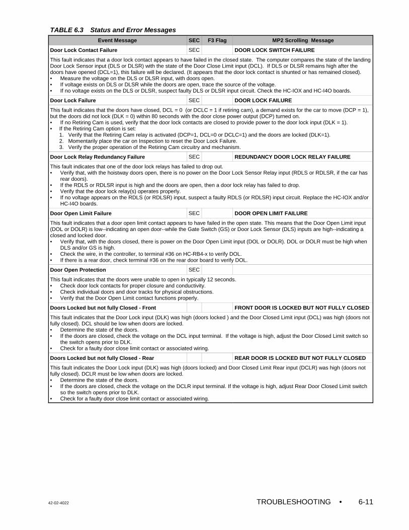
TABLE 6.3 Status and Error Messages
Event Message SEC F3 Flag MP2 Scrolling Message
42-02-4022 TROUBLESHOOTING • 6-11
Door Lock Contact Failure SEC DOOR LOCK SWITCH FAILURE
This fault indicates that a door lock contact appears to have failed in the closed state. The computer compares the state of the landingDoor Lock Sensor input (DLS or DLSR) with the state of the Door Close Limit input (DCL). If DLS or DLSR remains high after thedoors have opened (DCL=1), this failure will be declared. (It appears that the door lock contact is shunted or has remained closed).• Measure the voltage on the DLS or DLSR input, with doors open. • If voltage exists on DLS or DLSR while the doors are open, trace the source of the voltage.• If no voltage exists on the DLS or DLSR, suspect faulty DLS or DLSR input circuit. Check the HC-IOX and HC-I4O boards.
Door Lock Failure SEC DOOR LOCK FAILURE
This fault indicates that the doors have closed, DCL = 0 (or DCLC = 1 if retiring cam), a demand exists for the car to move (DCP = 1),but the doors did not lock (DLK = 0) within 80 seconds with the door close power output (DCP) turned on.• If no Retiring Cam is used, verify that the door lock contacts are closed to provide power to the door lock input (DLK = 1).• If the Retiring Cam option is set:
1. Verify that the Retiring Cam relay is activated (DCP=1, DCL=0 or DCLC=1) and the doors are locked (DLK=1).2. Momentarily place the car on Inspection to reset the Door Lock Failure. 3. Verify the proper operation of the Retiring Cam circuitry and mechanism.
Door Lock Relay Redundancy Failure SEC REDUNDANCY DOOR LOCK RELAY FAILURE
This fault indicates that one of the door lock relays has failed to drop out.• Verify that, with the hoistway doors open, there is no power on the Door Lock Sensor Relay input (RDLS or RDLSR, if the car has
rear doors). • If the RDLS or RDLSR input is high and the doors are open, then a door lock relay has failed to drop.• Verify that the door lock relay(s) operates properly. • If no voltage appears on the RDLS (or RDLSR) input, suspect a faulty RDLS (or RDLSR) input circuit. Replace the HC-IOX and/or
HC-I4O boards.
Door Open Limit Failure SEC DOOR OPEN LIMIT FAILURE
This fault indicates that a door open limit contact appears to have failed in the open state. This means that the Door Open Limit input(DOL or DOLR) is low--indicating an open door--while the Gate Switch (GS) or Door Lock Sensor (DLS) inputs are high--indicating aclosed and locked door.• Verify that, with the doors closed, there is power on the Door Open Limit input (DOL or DOLR). DOL or DOLR must be high when
DLS and/or GS is high.• Check the wire, in the controller, to terminal #36 on HC-RB4-x to verify DOL.• If there is a rear door, check terminal #36 on the rear door board to verify DOL.
Door Open Protection SEC
This fault indicates that the doors were unable to open in typically 12 seconds.• Check door lock contacts for proper closure and conductivity.• Check individual doors and door tracks for physical obstructions.• Verify that the Door Open Limit contact functions properly.
Doors Locked but not fully Closed - Front FRONT DOOR IS LOCKED BUT NOT FULLY CLOSED
This fault indicates that the Door Lock input (DLK) was high (doors locked ) and the Door Closed Limit input (DCL) was high (doors notfully closed). DCL should be low when doors are locked.• Determine the state of the doors.• If the doors are closed, check the voltage on the DCL input terminal. If the voltage is high, adjust the Door Closed Limit switch so
the switch opens prior to DLK.• Check for a faulty door close limit contact or associated wiring.
Doors Locked but not fully Closed - Rear REAR DOOR IS LOCKED BUT NOT FULLY CLOSED
This fault indicates the Door Lock input (DLK) was high (doors locked) and Door Closed Limit Rear input (DCLR) was high (doors notfully closed). DCLR must be low when doors are locked.• Determine the state of the doors.• If the doors are closed, check the voltage on the DCLR input terminal. If the voltage is high, adjust Rear Door Closed Limit switch
so the switch opens prior to DLK.• Check for a faulty door close limit contact or associated wiring.
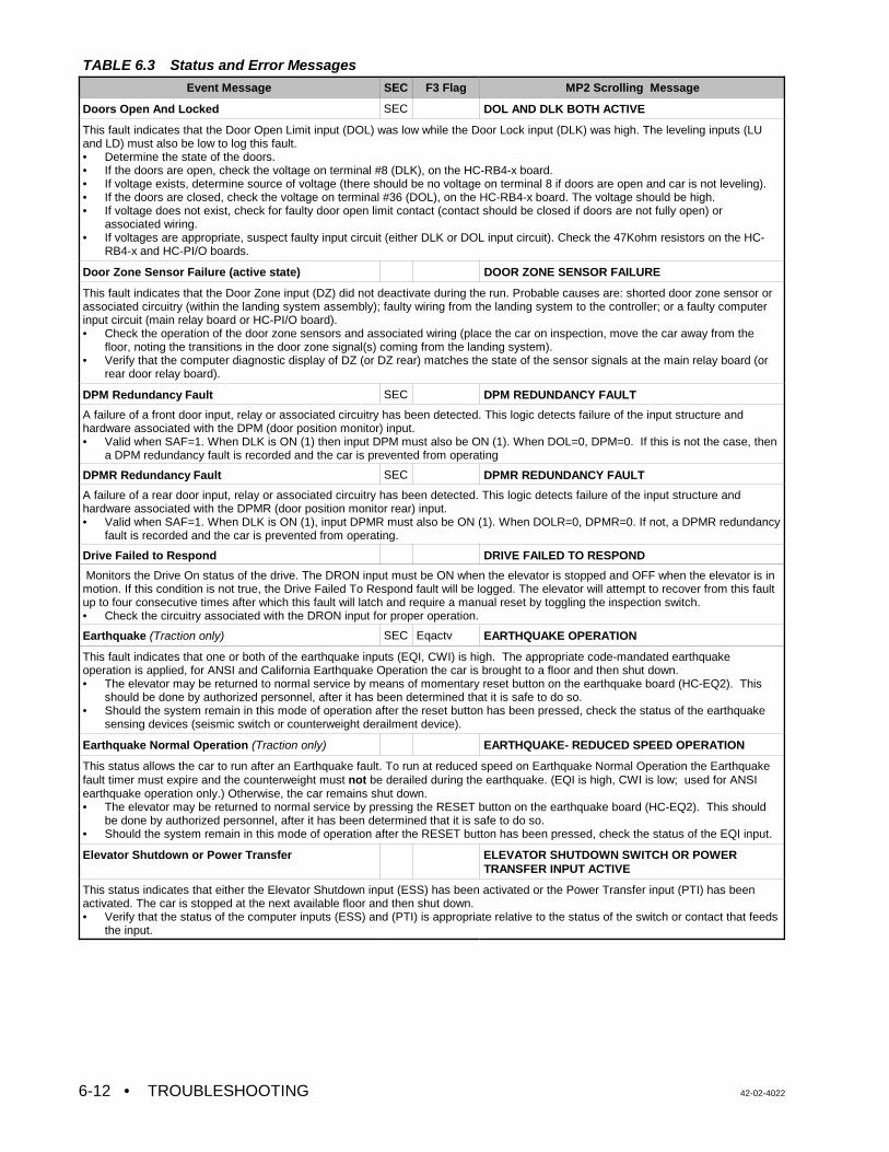
TABLE 6.3 Status and Error Messages
Event Message SEC F3 Flag MP2 Scrolling Message
• TROUBLESHOOTING 42-02-40226-12
Doors Open And Locked SEC DOL AND DLK BOTH ACTIVE
This fault indicates that the Door Open Limit input (DOL) was low while the Door Lock input (DLK) was high. The leveling inputs (LUand LD) must also be low to log this fault.• Determine the state of the doors. • If the doors are open, check the voltage on terminal #8 (DLK), on the HC-RB4-x board. • If voltage exists, determine source of voltage (there should be no voltage on terminal 8 if doors are open and car is not leveling). • If the doors are closed, check the voltage on terminal #36 (DOL), on the HC-RB4-x board. The voltage should be high. • If voltage does not exist, check for faulty door open limit contact (contact should be closed if doors are not fully open) or
associated wiring. • If voltages are appropriate, suspect faulty input circuit (either DLK or DOL input circuit). Check the 47Kohm resistors on the HC-
RB4-x and HC-PI/O boards.
Door Zone Sensor Failure (active state) DOOR ZONE SENSOR FAILURE
This fault indicates that the Door Zone input (DZ) did not deactivate during the run. Probable causes are: shorted door zone sensor orassociated circuitry (within the landing system assembly); faulty wiring from the landing system to the controller; or a faulty computerinput circuit (main relay board or HC-PI/O board). • Check the operation of the door zone sensors and associated wiring (place the car on inspection, move the car away from the
floor, noting the transitions in the door zone signal(s) coming from the landing system). • Verify that the computer diagnostic display of DZ (or DZ rear) matches the state of the sensor signals at the main relay board (or
rear door relay board).
DPM Redundancy Fault SEC DPM REDUNDANCY FAULT
A failure of a front door input, relay or associated circuitry has been detected. This logic detects failure of the input structure andhardware associated with the DPM (door position monitor) input. • Valid when SAF=1. When DLK is ON (1) then input DPM must also be ON (1). When DOL=0, DPM=0. If this is not the case, then
a DPM redundancy fault is recorded and the car is prevented from operating
DPMR Redundancy Fault SEC DPMR REDUNDANCY FAULT
A failure of a rear door input, relay or associated circuitry has been detected. This logic detects failure of the input structure andhardware associated with the DPMR (door position monitor rear) input.• Valid when SAF=1. When DLK is ON (1), input DPMR must also be ON (1). When DOLR=0, DPMR=0. If not, a DPMR redundancy
fault is recorded and the car is prevented from operating.
Drive Failed to Respond DRIVE FAILED TO RESPOND
Monitors the Drive On status of the drive. The DRON input must be ON when the elevator is stopped and OFF when the elevator is inmotion. If this condition is not true, the Drive Failed To Respond fault will be logged. The elevator will attempt to recover from this faultup to four consecutive times after which this fault will latch and require a manual reset by toggling the inspection switch.• Check the circuitry associated with the DRON input for proper operation.
Earthquake (Traction only) SEC Eqactv EARTHQUAKE OPERATION
This fault indicates that one or both of the earthquake inputs (EQI, CWI) is high. The appropriate code-mandated earthquakeoperation is applied, for ANSI and California Earthquake Operation the car is brought to a floor and then shut down.• The elevator may be returned to normal service by means of momentary reset button on the earthquake board (HC-EQ2). This
should be done by authorized personnel, after it has been determined that it is safe to do so. • Should the system remain in this mode of operation after the reset button has been pressed, check the status of the earthquake
sensing devices (seismic switch or counterweight derailment device).
Earthquake Normal Operation (Traction only) EARTHQUAKE- REDUCED SPEED OPERATION
This status allows the car to run after an Earthquake fault. To run at reduced speed on Earthquake Normal Operation the Earthquakefault timer must expire and the counterweight must not be derailed during the earthquake. (EQI is high, CWI is low; used for ANSIearthquake operation only.) Otherwise, the car remains shut down.• The elevator may be returned to normal service by pressing the RESET button on the earthquake board (HC-EQ2). This should
be done by authorized personnel, after it has been determined that it is safe to do so. • Should the system remain in this mode of operation after the RESET button has been pressed, check the status of the EQI input.
Elevator Shutdown or Power Transfer ELEVATOR SHUTDOWN SWITCH OR POWERTRANSFER INPUT ACTIVE
This status indicates that either the Elevator Shutdown input (ESS) has been activated or the Power Transfer input (PTI) has beenactivated. The car is stopped at the next available floor and then shut down.• Verify that the status of the computer inputs (ESS) and (PTI) is appropriate relative to the status of the switch or contact that feeds
the input.
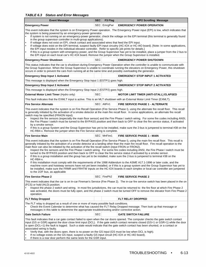
TABLE 6.3 Status and Error Messages
Event Message SEC F3 Flag MP2 Scrolling Message
42-02-4022 TROUBLESHOOTING • 6-13
Emergency Power SEC EmrgPwr EMERGENCY POWER OPERATION
This event indicates that the system is on Emergency Power operation. The Emergency Power input (EPI) is low, which indicates thatthe system is being powered by an emergency-power generator.• If system is not running on an emergency-power generator, check the voltage on the EPI terminal (this terminal is generally found
in the group supervisor controller in multi-group applications). • If voltage does not exist on EPI, check contact and associated wires that feed the EPI input. • If voltage does exist on the EPI terminal, suspect faulty EPI input circuitry (HC-IOX or HC-I4O board). [Note: In some applications,
the EPI input resides in the individual elevator controller. Refer to specific job prints for details.]• If this is a group system with emergency power, and the Group Supervisor has yet to be installed, place a jumper from the 2 bus to
the EPI input on each local car’s HC-IOX board. Remove the jumper when the Group Supervisor is installed.
Emergency Power Shutdown SEC EMERGENCY POWER SHUTDOWN
This status indicates that the car is shutdown during Emergency Power Operation when the controller is unable to communicate withthe Group Supervisor. When the Group Supervisor is unable to coordinate running the elevators on Emergency Power, this shutdownoccurs in order to prevent the cars from running all at the same time and possibly overloading the generator.
Emergency Stop Input 1 Activated EMERGENCY STOP INPUT 1 ACTIVATED
This message is displayed when the Emergency Stop Input 1 (ESTP1) goes high.
Emergency Stop Input 2 Activated EMERGENCY STOP INPUT 2 ACTIVATED
This message is displayed when the Emergency Stop Input 2 (ESTP2) goes high.
External Motor Limit Timer (Hydro only) SEC MOTOR LIMIT TIMER (ANTI-STALL) ELAPSED
This fault indicates that the EXMLT input is active. This is an MLT shutdown wtih an External Motor Limit Timer (EXMLT).
Fire Service Alternate SEC AltFir1 FIRE SERVICE PHASE 1 - ALTERNATE
This event indicates that the system is on Fire Recall Operation (Fire Service Phase I), using the alternate fire recall floor. This recallis generally initiated by the activation of a smoke detector at the main fire recall floor. In some applications, an alternate fire recallswitch may be specified (FRAON input). • Inspect the fire sensors (especially the main floor sensor) and the Fire Phase I switch wiring. For some fire codes including ANSI,
the Fire Phase I switch must be turned to the BYPASS position and then back to OFF to clear the fire service status, if activatedby a smoke sensor.
• If this is a group System and the Group Supervisor has yet to be installed, make sure the 2-bus is jumpered to terminal #38 on theHC-RB4-x. Remove the jumper when the Fire Service wiring is complete.
Fire Service Main SEC MnFire1 FIRE SERVICE PHASE 1 - MAIN
This event indicates that the system is on Fire Recall Operation (Fire Service Phase I), using the main fire recall floor. This recall isgenerally initiated by the activation of a smoke detector at a landing other than the main fire recall floor. Fire recall operation to themain floor can also be initiated by the activation of the fire recall switch (input FRON or FRON2).• Inspect the fire sensors and the Fire Phase I switch wiring. For some fire codes including ANSI, the Fire Phase I switch must be
turned to the BYPASS position and then back to OFF to clear the fire service status if activated by a smoke sensor.• If this is a group installation and the group has yet to be installed, make sure the 2-bus is jumpered to terminal #38 on the
HC-RB4-x.• If this installation must comply with the requirements of the 1998 Addendum to the ASME A17.1-1996 or later code, and the
machine room and hoistway sensors have not yet been installed, or if this is a group system and the Group Supervisor has yet tobe installed, make sure the FRMR and FRHTW inputs on the HC-IOX boards in each simplex or local car controller are jumperedto the 2/2F bus, as applicable
Fire Service Phase 2 SEC FirePh2 FIRE SERVICE PHASE 2
This event indicates that the car is on In-car Fireman’s Service (Fire Phase 2). The in-car fire service switch has been placed in the on(FCS) or hold (HLD) position.• Inspect the phase 2 switch and wiring. In most fire jurisdictions, the car must be returned to the fire floor at which Fire Phase 2
was activated, the doors must be fully open, and the phase 2 switch must be turned OFF to remove the elevator from Fire Phase 2operation.
FLT Relay Dropped FLT RELAY DROPPED
The FLT relay is dropped as a result of one or more of many possible fault conditions.• Check the Event Calendar to determine what has caused the FLT Relay Dropped message. Then look up that message or
messages in this table to determine the appropriate troubleshooting and/or corrective action.
Gate Switch Failure SEC GATE SWITCH FAILURE
This fault indicates that a car gate contact failed to open when the car doors opened. The computer checks the gate switch contactinput (GS or GSR) against the door close limit input (DCL). If the gate switch contact remains closed (GS=1 or GSR=1) while the dooris open (DCL=1) the fault is logged. Such a state would indicate that the gate switch contact has been shunted, or a contact orassociated wiring is faulty. • Verify that, with the doors open, there is no power on the GS input (GS must be low when DCL is high). • If no voltage exists on the GS input, suspect a faulty GS input circuit (HC-IOX or HC-I4O board). • If there is a rear door perform the same tests for the GSR input.
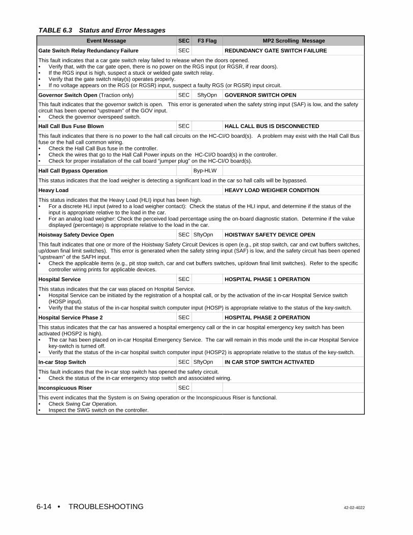
TABLE 6.3 Status and Error Messages
Event Message SEC F3 Flag MP2 Scrolling Message
• TROUBLESHOOTING 42-02-40226-14
Gate Switch Relay Redundancy Failure SEC REDUNDANCY GATE SWITCH FAILURE
This fault indicates that a car gate switch relay failed to release when the doors opened.• Verify that, with the car gate open, there is no power on the RGS input (or RGSR, if rear doors). • If the RGS input is high, suspect a stuck or welded gate switch relay.• Verify that the gate switch relay(s) operates properly. • If no voltage appears on the RGS (or RGSR) input, suspect a faulty RGS (or RGSR) input circuit.
Governor Switch Open (Traction only) SEC SftyOpn GOVERNOR SWITCH OPEN
This fault indicates that the governor switch is open. This error is generated when the safety string input (SAF) is low, and the safetycircuit has been opened “upstream” of the GOV input.• Check the governor overspeed switch.
Hall Call Bus Fuse Blown SEC HALL CALL BUS IS DISCONNECTED
This fault indicates that there is no power to the hall call circuits on the HC-CI/O board(s). A problem may exist with the Hall Call Busfuse or the hall call common wiring.• Check the Hall Call Bus fuse in the controller. • Check the wires that go to the Hall Call Power inputs on the HC-CI/O board(s) in the controller. • Check for proper installation of the call board “jumper plug” on the HC-CI/O board(s).
Hall Call Bypass Operation Byp-HLW
This status indicates that the load weigher is detecting a significant load in the car so hall calls will be bypassed.
Heavy Load HEAVY LOAD WEIGHER CONDITION
This status indicates that the Heavy Load (HLI) input has been high.• For a discrete HLI input (wired to a load weigher contact): Check the status of the HLI input, and determine if the status of the
input is appropriate relative to the load in the car. • For an analog load weigher: Check the perceived load percentage using the on-board diagnostic station. Determine if the value
displayed (percentage) is appropriate relative to the load in the car.
Hoistway Safety Device Open SEC SftyOpn HOISTWAY SAFETY DEVICE OPEN
This fault indicates that one or more of the Hoistway Safety Circuit Devices is open (e.g., pit stop switch, car and cwt buffers switches,up/down final limit switches). This error is generated when the safety string input (SAF) is low, and the safety circuit has been opened“upstream” of the SAFH input.• Check the applicable items (e.g., pit stop switch, car and cwt buffers switches, up/down final limit switches). Refer to the specific
controller wiring prints for applicable devices.
Hospital Service SEC HOSPITAL PHASE 1 OPERATION
This status indicates that the car was placed on Hospital Service. • Hospital Service can be initiated by the registration of a hospital call, or by the activation of the in-car Hospital Service switch
(HOSP input).• Verify that the status of the in-car hospital switch computer input (HOSP) is appropriate relative to the status of the key-switch.
Hospital Service Phase 2 SEC HOSPITAL PHASE 2 OPERATION
This status indicates that the car has answered a hospital emergency call or the in car hospital emergency key switch has beenactivated (HOSP2 is high).• The car has been placed on in-car Hospital Emergency Service. The car will remain in this mode until the in-car Hospital Service
key-switch is turned off. • Verify that the status of the in-car hospital switch computer input (HOSP2) is appropriate relative to the status of the key-switch.
In-car Stop Switch SEC SftyOpn IN CAR STOP SWITCH ACTIVATED
This fault indicates that the in-car stop switch has opened the safety circuit.• Check the status of the in-car emergency stop switch and associated wiring.
Inconspicuous Riser SEC
This event indicates that the System is on Swing operation or the Inconspicuous Riser is functional.• Check Swing Car Operation.• Inspect the SWG switch on the controller.
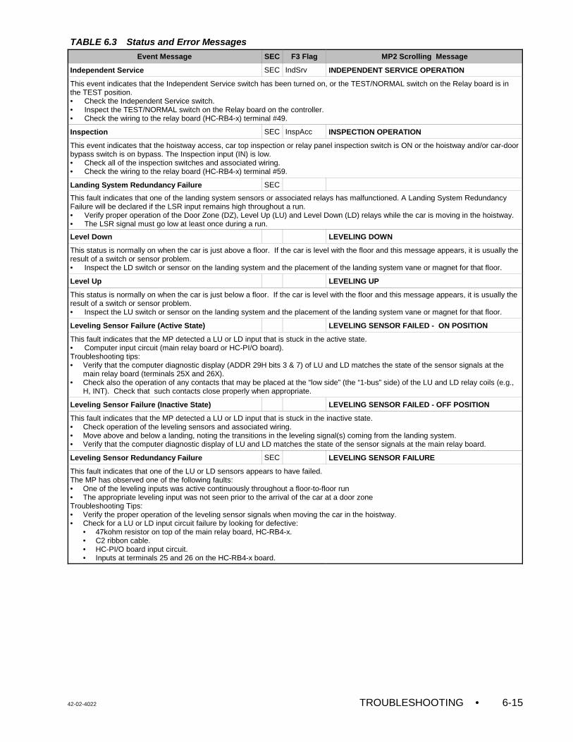
TABLE 6.3 Status and Error Messages
Event Message SEC F3 Flag MP2 Scrolling Message
42-02-4022 TROUBLESHOOTING • 6-15
Independent Service SEC IndSrv INDEPENDENT SERVICE OPERATION
This event indicates that the Independent Service switch has been turned on, or the TEST/NORMAL switch on the Relay board is inthe TEST position.• Check the Independent Service switch. • Inspect the TEST/NORMAL switch on the Relay board on the controller.• Check the wiring to the relay board (HC-RB4-x) terminal #49.
Inspection SEC InspAcc INSPECTION OPERATION
This event indicates that the hoistway access, car top inspection or relay panel inspection switch is ON or the hoistway and/or car-doorbypass switch is on bypass. The Inspection input (IN) is low.• Check all of the inspection switches and associated wiring.• Check the wiring to the relay board (HC-RB4-x) terminal #59.
Landing System Redundancy Failure SEC
This fault indicates that one of the landing system sensors or associated relays has malfunctioned. A Landing System RedundancyFailure will be declared if the LSR input remains high throughout a run.• Verify proper operation of the Door Zone (DZ), Level Up (LU) and Level Down (LD) relays while the car is moving in the hoistway.• The LSR signal must go low at least once during a run.
Level Down LEVELING DOWN
This status is normally on when the car is just above a floor. If the car is level with the floor and this message appears, it is usually theresult of a switch or sensor problem.• Inspect the LD switch or sensor on the landing system and the placement of the landing system vane or magnet for that floor.
Level Up LEVELING UP
This status is normally on when the car is just below a floor. If the car is level with the floor and this message appears, it is usually theresult of a switch or sensor problem.• Inspect the LU switch or sensor on the landing system and the placement of the landing system vane or magnet for that floor.
Leveling Sensor Failure (Active State) LEVELING SENSOR FAILED - ON POSITION
This fault indicates that the MP detected a LU or LD input that is stuck in the active state.• Computer input circuit (main relay board or HC-PI/O board). Troubleshooting tips:• Verify that the computer diagnostic display (ADDR 29H bits 3 & 7) of LU and LD matches the state of the sensor signals at the
main relay board (terminals 25X and 26X). • Check also the operation of any contacts that may be placed at the “low side” (the “1-bus” side) of the LU and LD relay coils (e.g.,
H, INT). Check that such contacts close properly when appropriate.
Leveling Sensor Failure (Inactive State) LEVELING SENSOR FAILED - OFF POSITION
This fault indicates that the MP detected a LU or LD input that is stuck in the inactive state. • Check operation of the leveling sensors and associated wiring.• Move above and below a landing, noting the transitions in the leveling signal(s) coming from the landing system. • Verify that the computer diagnostic display of LU and LD matches the state of the sensor signals at the main relay board.
Leveling Sensor Redundancy Failure SEC LEVELING SENSOR FAILURE
This fault indicates that one of the LU or LD sensors appears to have failed. The MP has observed one of the following faults:• One of the leveling inputs was active continuously throughout a floor-to-floor run• The appropriate leveling input was not seen prior to the arrival of the car at a door zoneTroubleshooting Tips:• Verify the proper operation of the leveling sensor signals when moving the car in the hoistway. • Check for a LU or LD input circuit failure by looking for defective:
• 47kohm resistor on top of the main relay board, HC-RB4-x.• C2 ribbon cable.• HC-PI/O board input circuit.• Inputs at terminals 25 and 26 on the HC-RB4-x board.
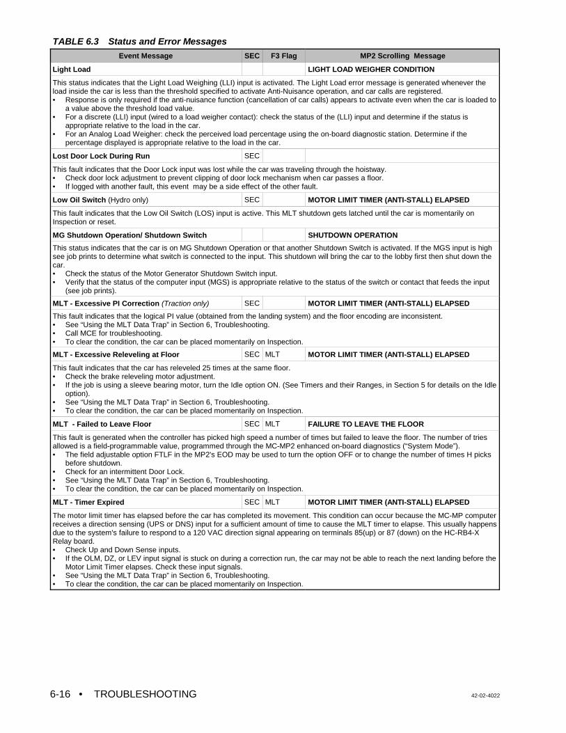
TABLE 6.3 Status and Error Messages
Event Message SEC F3 Flag MP2 Scrolling Message
• TROUBLESHOOTING 42-02-40226-16
Light Load LIGHT LOAD WEIGHER CONDITION
This status indicates that the Light Load Weighing (LLI) input is activated. The Light Load error message is generated whenever theload inside the car is less than the threshold specified to activate Anti-Nuisance operation, and car calls are registered.• Response is only required if the anti-nuisance function (cancellation of car calls) appears to activate even when the car is loaded to
a value above the threshold load value. • For a discrete (LLI) input (wired to a load weigher contact): check the status of the (LLI) input and determine if the status is
appropriate relative to the load in the car. • For an Analog Load Weigher: check the perceived load percentage using the on-board diagnostic station. Determine if the
percentage displayed is appropriate relative to the load in the car.
Lost Door Lock During Run SEC
This fault indicates that the Door Lock input was lost while the car was traveling through the hoistway. • Check door lock adjustment to prevent clipping of door lock mechanism when car passes a floor. • If logged with another fault, this event may be a side effect of the other fault.
Low Oil Switch (Hydro only) SEC MOTOR LIMIT TIMER (ANTI-STALL) ELAPSED
This fault indicates that the Low Oil Switch (LOS) input is active. This MLT shutdown gets latched until the car is momentarily onInspection or reset.
MG Shutdown Operation/ Shutdown Switch SHUTDOWN OPERATION
This status indicates that the car is on MG Shutdown Operation or that another Shutdown Switch is activated. If the MGS input is highsee job prints to determine what switch is connected to the input. This shutdown will bring the car to the lobby first then shut down thecar.• Check the status of the Motor Generator Shutdown Switch input. • Verify that the status of the computer input (MGS) is appropriate relative to the status of the switch or contact that feeds the input
(see job prints).
MLT - Excessive PI Correction (Traction only) SEC MOTOR LIMIT TIMER (ANTI-STALL) ELAPSED
This fault indicates that the logical PI value (obtained from the landing system) and the floor encoding are inconsistent.• See “Using the MLT Data Trap” in Section 6, Troubleshooting.• Call MCE for troubleshooting.• To clear the condition, the car can be placed momentarily on Inspection.
MLT - Excessive Releveling at Floor SEC MLT MOTOR LIMIT TIMER (ANTI-STALL) ELAPSED
This fault indicates that the car has releveled 25 times at the same floor.• Check the brake releveling motor adjustment.• If the job is using a sleeve bearing motor, turn the Idle option ON. (See Timers and their Ranges, in Section 5 for details on the Idle
option).• See “Using the MLT Data Trap” in Section 6, Troubleshooting.• To clear the condition, the car can be placed momentarily on Inspection.
MLT - Failed to Leave Floor SEC MLT FAILURE TO LEAVE THE FLOOR
This fault is generated when the controller has picked high speed a number of times but failed to leave the floor. The number of triesallowed is a field-programmable value, programmed through the MC-MP2 enhanced on-board diagnostics (“System Mode”).• The field adjustable option FTLF in the MP2's EOD may be used to turn the option OFF or to change the number of times H picks
before shutdown.• Check for an intermittent Door Lock.• See “Using the MLT Data Trap” in Section 6, Troubleshooting.• To clear the condition, the car can be placed momentarily on Inspection.
MLT - Timer Expired SEC MLT MOTOR LIMIT TIMER (ANTI-STALL) ELAPSED
The motor limit timer has elapsed before the car has completed its movement. This condition can occur because the MC-MP computerreceives a direction sensing (UPS or DNS) input for a sufficient amount of time to cause the MLT timer to elapse. This usually happensdue to the system's failure to respond to a 120 VAC direction signal appearing on terminals 85(up) or 87 (down) on the HC-RB4-XRelay board.• Check Up and Down Sense inputs.• If the OLM, DZ, or LEV input signal is stuck on during a correction run, the car may not be able to reach the next landing before the
Motor Limit Timer elapses. Check these input signals.• See “Using the MLT Data Trap” in Section 6, Troubleshooting.• To clear the condition, the car can be placed momentarily on Inspection.
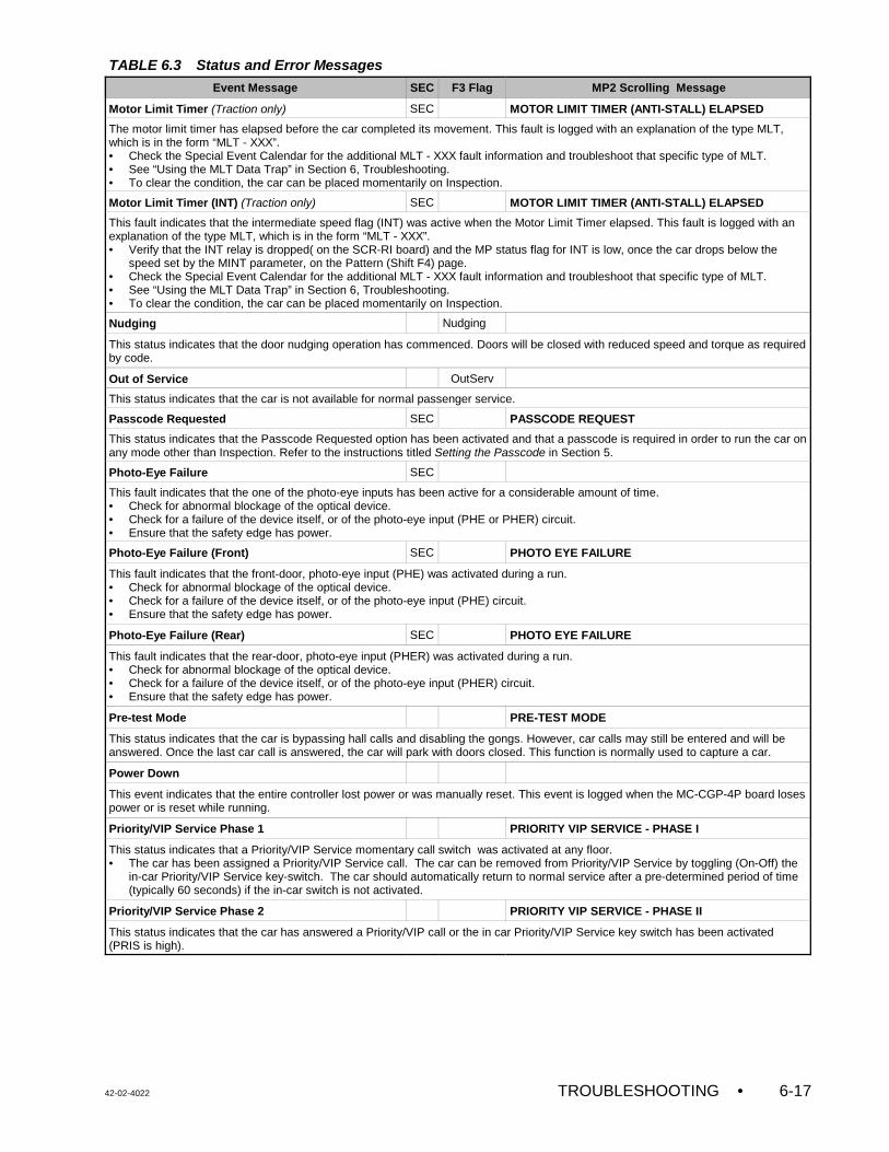
TABLE 6.3 Status and Error Messages
Event Message SEC F3 Flag MP2 Scrolling Message
42-02-4022 TROUBLESHOOTING • 6-17
Motor Limit Timer (Traction only) SEC MOTOR LIMIT TIMER (ANTI-STALL) ELAPSED
The motor limit timer has elapsed before the car completed its movement. This fault is logged with an explanation of the type MLT,which is in the form “MLT - XXX”. • Check the Special Event Calendar for the additional MLT - XXX fault information and troubleshoot that specific type of MLT.• See “Using the MLT Data Trap” in Section 6, Troubleshooting.• To clear the condition, the car can be placed momentarily on Inspection.
Motor Limit Timer (INT) (Traction only) SEC MOTOR LIMIT TIMER (ANTI-STALL) ELAPSED
This fault indicates that the intermediate speed flag (INT) was active when the Motor Limit Timer elapsed. This fault is logged with anexplanation of the type MLT, which is in the form “MLT - XXX”. • Verify that the INT relay is dropped( on the SCR-RI board) and the MP status flag for INT is low, once the car drops below the
speed set by the MINT parameter, on the Pattern (Shift F4) page.• Check the Special Event Calendar for the additional MLT - XXX fault information and troubleshoot that specific type of MLT.• See “Using the MLT Data Trap” in Section 6, Troubleshooting.• To clear the condition, the car can be placed momentarily on Inspection.
Nudging Nudging
This status indicates that the door nudging operation has commenced. Doors will be closed with reduced speed and torque as requiredby code.
Out of Service OutServ
This status indicates that the car is not available for normal passenger service.
Passcode Requested SEC PASSCODE REQUEST
This status indicates that the Passcode Requested option has been activated and that a passcode is required in order to run the car onany mode other than Inspection. Refer to the instructions titled Setting the Passcode in Section 5.
Photo-Eye Failure SEC
This fault indicates that the one of the photo-eye inputs has been active for a considerable amount of time.• Check for abnormal blockage of the optical device.• Check for a failure of the device itself, or of the photo-eye input (PHE or PHER) circuit.• Ensure that the safety edge has power.
Photo-Eye Failure (Front) SEC PHOTO EYE FAILURE
This fault indicates that the front-door, photo-eye input (PHE) was activated during a run.• Check for abnormal blockage of the optical device.• Check for a failure of the device itself, or of the photo-eye input (PHE) circuit.• Ensure that the safety edge has power.
Photo-Eye Failure (Rear) SEC PHOTO EYE FAILURE
This fault indicates that the rear-door, photo-eye input (PHER) was activated during a run.• Check for abnormal blockage of the optical device.• Check for a failure of the device itself, or of the photo-eye input (PHER) circuit.• Ensure that the safety edge has power.
Pre-test Mode PRE-TEST MODE
This status indicates that the car is bypassing hall calls and disabling the gongs. However, car calls may still be entered and will beanswered. Once the last car call is answered, the car will park with doors closed. This function is normally used to capture a car.
Power Down
This event indicates that the entire controller lost power or was manually reset. This event is logged when the MC-CGP-4P board losespower or is reset while running.
Priority/VIP Service Phase 1 PRIORITY VIP SERVICE - PHASE I
This status indicates that a Priority/VIP Service momentary call switch was activated at any floor.• The car has been assigned a Priority/VIP Service call. The car can be removed from Priority/VIP Service by toggling (On-Off) the
in-car Priority/VIP Service key-switch. The car should automatically return to normal service after a pre-determined period of time(typically 60 seconds) if the in-car switch is not activated.
Priority/VIP Service Phase 2 PRIORITY VIP SERVICE - PHASE II
This status indicates that the car has answered a Priority/VIP call or the in car Priority/VIP Service key switch has been activated(PRIS is high).
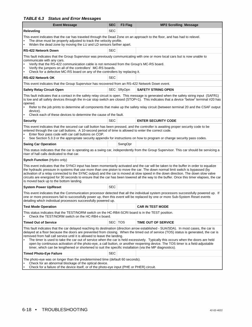
TABLE 6.3 Status and Error Messages
Event Message SEC F3 Flag MP2 Scrolling Message
• TROUBLESHOOTING 42-02-40226-18
Releveling SEC
This event indicates that the car has traveled through the Dead Zone on an approach to the floor, and has had to relevel. • The drive must be properly adjusted to track the velocity profile. • Widen the dead zone by moving the LU and LD sensors farther apart.
RS-422 Network Down SEC
This fault indicates that the Group Supervisor was previously communicating with one or more local cars but is now unable tocommunicate with any cars.• Verify that the RS-422 communication cable is not removed from the Group's MC-RS board.• Verify the jumpers on all of the controllers' MC-RS boards.• Check for a defective MC-RS board on any of the controllers by replacing it.
RS-422 Network OK SEC
This event indicates that the Group Supervisor has recovered from an RS-422 Network Down event.
Safety Relay Circuit Open SEC SftyOpn SAFETY STRING OPEN
This fault indicates that a contact in the safety relay circuit is open. This message is generated when the safety string input (SAFR1)is low and all safety devices through the in-car stop switch are closed (STOP=1). This indicates that a device “below” terminal #20 hasopened. • Refer to the job prints to determine all components that make up the safety relay circuit (between terminal 20 and the CSAF output
device). • Check each of these devices to determine the cause of the fault.
Security SEC ENTER SECURITY CODE
This event indicates that the secured car call button has been pressed, and the controller is awaiting proper security code to beentered through the car call buttons. A 10-second period of time is allowed to enter the correct code.• Enter floor pass code with car call buttons on COP.• See Section 5.3.3 or the appropriate security appendix for instructions on how to program or change security pass codes.
Swing Car Operation SwngOpr
This status indicates that the car is operating as a swing car, independently from the Group Supervisor. This car should be servicing ariser of hall calls dedicated to that car.
Synch Function (Hydro only)
This event indicates that the SYNCI input has been momentarily activated and the car will be taken to the buffer in order to equalizethe hydraulic pressure in systems that use more than one piston to move the car. The down normal limit switch is bypassed (byactivation of a relay connected to the SYNC output) and the car is moved at slow speed in the down direction. The down slow valvecircuits are energized for 30 seconds to ensure that the car has been lowered all the way to the buffer. Once this timer elapses, the caris moved back up to the bottom landing.
System Power Up/Reset SEC
This event indicates that the Communication processor detected that all the individual system processors successfully powered up. Ifone or more processors fail to successfully power up, then this event will be replaced by one or more Sub-System Reset eventsdetailing which individual processors successfully powered up.
Test Mode Operation CAR IN TEST MODE
This status indicates that the TEST/NORM switch on the HC-RB4-SCRI board is in the TEST position.• Check the TEST/NORM switch on the HC-RB4-x board.
Timed Out of Service SEC TOS TIME OUT OF SERVICE
This fault indicates that the car delayed reaching its destination (direction arrow established - SUA/SDA). In most cases, the car isdelayed at a floor because the doors are prevented from closing. When the timed out of service (TOS) status is generated, the car isremoved from hall call service until it is allowed to leave the landing.• The timer is used to take the car out of service when the car is held excessively. Typically this occurs when the doors are held
open by continuous activation of the photo-eye, a call button, or another reopening device. The TOS timer is a field-adjustabletimer, which can be lengthened or shortened to suit the specific installation (via the MP diagnostics).
Timed Photo-Eye Failure SEC
The photo-eye was on longer than the predetermined time (default 60 seconds).• Check for an abnormal blockage of the optical device.• Check for a failure of the device itself, or of the photo-eye input (PHE or PHER) circuit.
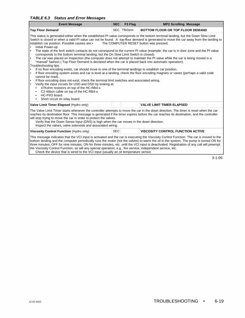
TABLE 6.3 Status and Error Messages
Event Message SEC F3 Flag MP2 Scrolling Message
42-02-4022 TROUBLESHOOTING • 6-19
Top Floor Demand SEC TflrDem BOTTOM FLOOR OR TOP FLOOR DEMAND
This status is generated either when the established PI value corresponds to the bottom terminal landing, but the Down Slow LimitSwitch is closed or when a valid PI value can not be found. A top-floor demand is generated to move the car away from the landing toestablish car position. Possible causes are:• The COMPUTER RESET button was pressed.• Initial Power-up.• The state of the limit switch contacts do not correspond to the current PI value (example: the car is in door zone and the PI value
corresponds to the bottom terminal landing, but the Dn Slow Limit Switch is closed).• The car was placed on Inspection (the computer does not attempt to maintain the PI value while the car is being moved in a
“manual” fashion ( Top Floor Demand is declared when the car is placed back into automatic operation).Troubleshooting tips: • If no floor encoding exists, car should move to one of the terminal landings to establish car position. • If floor encoding system exists and car is level at a landing, check the floor encoding magnets or vanes (perhaps a valid code
cannot be read). • If floor encoding does not exist, check the terminal limit switches and associated wiring. • Verify the input circuits for USD and DSD by looking at:
• 47Kohm resistors on top of the HC-RB4-x.• C2 ribbon cable on top of the HC-RB4-x.• HC-PI/O board.• Short circuit on relay board.
Valve Limit Timer Elapsed (Hydro only) VALVE LIMIT TIMER ELAPSED
The Valve Limit Timer starts whenever the controller attempts to move the car in the down direction. The timer is reset when the carreaches its destination floor. This message is generated if the timer expires before the car reaches its destination, and the controllerwill stop trying to move the car in order to protect the valves. Verify that the Down Sense Input (DNS) is high when the car moves in the down direction. Inspect the valves, valve solenoids and associated wiring.
Viscosity Control Function (Hydro only) SEC VISCOSITY CONTROL FUNCTION ACTIVE
This message indicates that the VCI input is activated and the car is executing the Viscosity Control Function. The car is moved to thebottom landing and the computer periodically runs the motor (not the valves) to warm the oil in the system. The pump is turned ON forthree minutes, OFF for nine minutes, ON for three minutes, etc. until the VCI input is deactivated. Registration of any call will preemptthe Viscosity Control Function, as will any special operation, e.g., fire service, independent service, etc. Check the device that is wired to the VCI input (usually an oil temperature sensor.
3-1-05
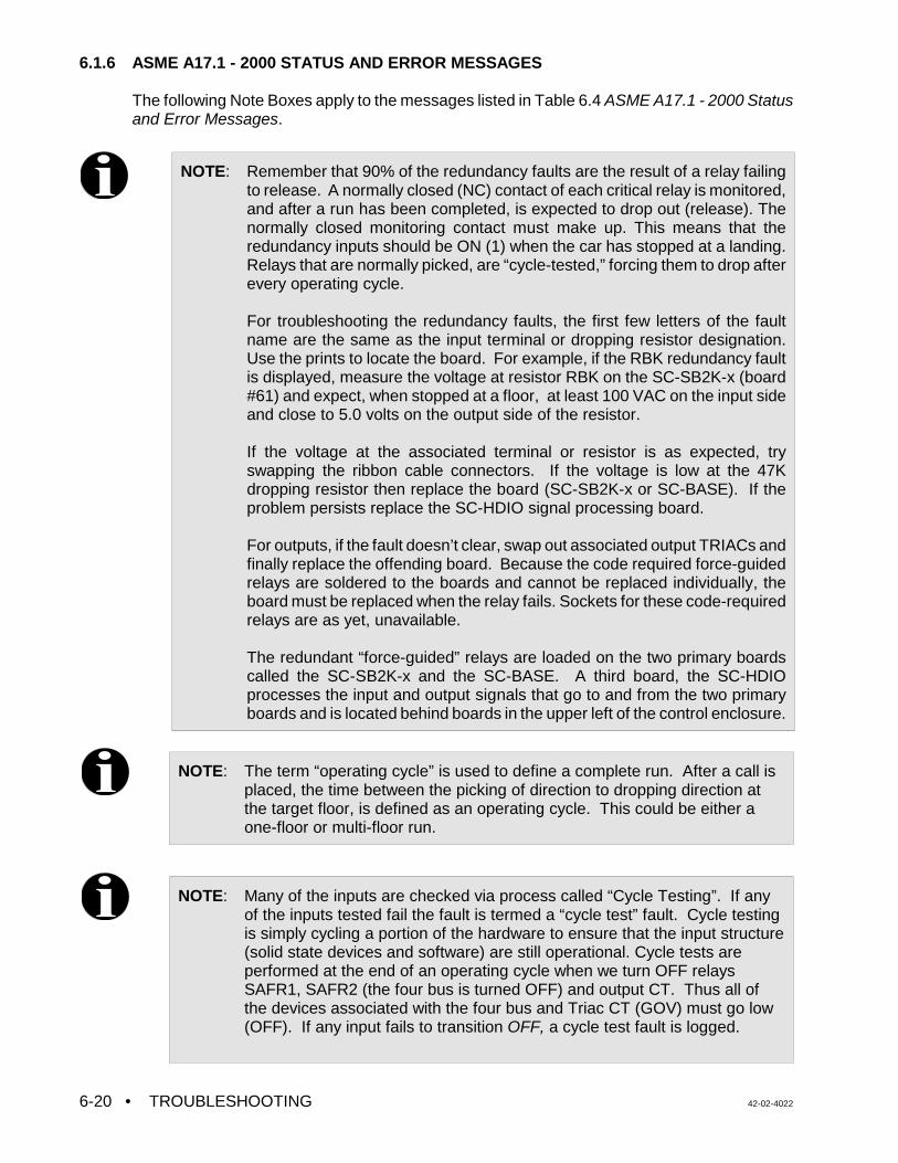
• TROUBLESHOOTING 42-02-40226-20
6.1.6 ASME A17.1 - 2000 STATUS AND ERROR MESSAGES
The following Note Boxes apply to the messages listed in Table 6.4 ASME A17.1 - 2000 Statusand Error Messages.
NOTE: Remember that 90% of the redundancy faults are the result of a relay failingto release. A normally closed (NC) contact of each critical relay is monitored,and after a run has been completed, is expected to drop out (release). Thenormally closed monitoring contact must make up. This means that theredundancy inputs should be ON (1) when the car has stopped at a landing.Relays that are normally picked, are “cycle-tested,” forcing them to drop afterevery operating cycle.
For troubleshooting the redundancy faults, the first few letters of the faultname are the same as the input terminal or dropping resistor designation.Use the prints to locate the board. For example, if the RBK redundancy faultis displayed, measure the voltage at resistor RBK on the SC-SB2K-x (board#61) and expect, when stopped at a floor, at least 100 VAC on the input sideand close to 5.0 volts on the output side of the resistor.
If the voltage at the associated terminal or resistor is as expected, tryswapping the ribbon cable connectors. If the voltage is low at the 47Kdropping resistor then replace the board (SC-SB2K-x or SC-BASE). If theproblem persists replace the SC-HDIO signal processing board.
For outputs, if the fault doesn’t clear, swap out associated output TRIACs andfinally replace the offending board. Because the code required force-guidedrelays are soldered to the boards and cannot be replaced individually, theboard must be replaced when the relay fails. Sockets for these code-requiredrelays are as yet, unavailable.
The redundant “force-guided” relays are loaded on the two primary boardscalled the SC-SB2K-x and the SC-BASE. A third board, the SC-HDIOprocesses the input and output signals that go to and from the two primaryboards and is located behind boards in the upper left of the control enclosure.
NOTE: The term “operating cycle” is used to define a complete run. After a call isplaced, the time between the picking of direction to dropping direction atthe target floor, is defined as an operating cycle. This could be either aone-floor or multi-floor run.
NOTE: Many of the inputs are checked via process called “Cycle Testing”. If anyof the inputs tested fail the fault is termed a “cycle test” fault. Cycle testing is simply cycling a portion of the hardware to ensure that the input structure(solid state devices and software) are still operational. Cycle tests areperformed at the end of an operating cycle when we turn OFF relaysSAFR1, SAFR2 (the four bus is turned OFF) and output CT. Thus all ofthe devices associated with the four bus and Triac CT (GOV) must go low(OFF). If any input fails to transition OFF, a cycle test fault is logged.
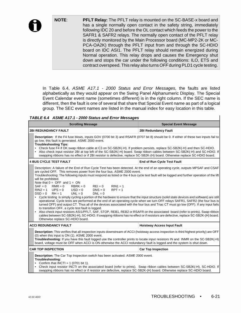
42-02-4022 TROUBLESHOOTING • 6-21
In Table 6.4, ASME A17.1 - 2000 Status and Error Messages, the faults are listedalphabetically as they would appear on the Swing Panel Alphanumeric Display. The SpecialEvent Calendar event name (sometimes different) is in the right column. If the SEC name isdifferent, then the fault is one of several that share that Special Event name as part of a logicalgroup. The SEC event names are listed in the manual index for easy location in this table.
TABLE 6.4 ASME A17.1 - 2000 Status and Error Messages
Scrolling Message Special Event Message
2BI REDUNDANCY FAULT 2BI Redundancy Fault
Description: If the F4 fuse blows, inputs GOV (0700 bit 3) and RSAFR (0707 bit 8) should be 0. If either of these two inputs fail togo low, this fault is generated. ASME 2000 event.Troubleshooting Tips:• Check fuse F4 if OK swap ribbon cable at C3 on SC-SB2K(-H). If problem persists, replace SC-SB2K(-H) and then SC-HDIO.• Also check input resistor 2BI at top left of the SC-SB2K(-H) board. Swap ribbon cables between SC-SB2K(-H) and SC-HDIO. If
swapping ribbons has no effect or if 2BI resistor is defective, replace SC-SB2K-(H) board. Otherwise replace SC-HDIO board.
4 BUS CYCLE TEST FAULT End of Run Cycle Test Fault
Description: A failure of the End of Run Cycle Test has been detected. At the end of an operating cycle, outputs MPSAF and CSAFare cycled OFF. This removes power from the four bus. ASME 2000 event. Troubleshooting: The following inputs must respond as listed or the 4 bus cycle test fault will be logged and further operation of the liftwill be prohibited.Note that 0 = OFF and 1 = ONSAF = 0 RMR = 0 RBRK = 0 REI = 0 RIN1 = 1 RIN2 = 1 UPS = 0 USD = 0 DNS = 0 RPT = 1DSD = 0 RH = 1 UNL = 0 DNL = 0• Cycle testing is simply cycling a portion of the hardware to ensure that the input structure (solid state devices and software) are still
operational. Cycle tests are performed at the end of an operating cycle when we turn OFF relays SAFR1, SAFR2 (the four bus isturned OFF) and output CT. Thus all of the devices associated with the four bus and Triac CT must go low (OFF). If any input failsto transition OFF, a cycle test fault is logged.
• Also check input resistors ASI1/PFLT, SAF, STOP, REB1, REB2 or RSAFR on the associated board (refer to prints). Swap ribboncables between SC-SB2K(-H), SC-HDIO. If swapping ribbons has no effect or if resistors are defective, replace SC-SB2K-(H) board.Otherwise replace SC-HDIO board.
ACCI REDUNDANCY FAULT Hoistway Access Input Fault
Description: This verifies that all inspection inputs downstream of ACCI (hoistway access inspection is third highest priority) are OFF(0) when this input is ON (1). ASME 2000 event. Troubleshooting: If you have this fault logged use the controller prints to locate input resistors IN and INMR on the SC-SB2K(-H)board, voltage must be OFF when ACCI is ON otherwise the ACCI redundancy fault is logged and the system is shut down.
CAR TOP INSPECTION Car Top Inspection
Description: The Car Top Inspection switch has been activated. ASME 2000 event.Troubleshooting: • Confirm that INCTI = 1 (0701 bit 1).• Check input resistor INCTI on the associated board (refer to prints). Swap ribbon cables between SC-SB2K(-H), SC-HDIO. If
swapping ribbons has no effect or if resistor are defective, replace SC-SB2K-(H) board. Otherwise replace SC-HDIO board.
NOTE: PFLT Relay: The PFLT relay is mounted on the SC-BASE-x board andhas a single normally open contact in the safety string, immediatelyfollowing IDC 20 and before the OL contact which feeds the power to theSAFR1 & SAFR2 relays. The normally open contact of the PFLT relayis directly monitored by the Main Processor board (MC-MP2-2K or MC-PCA-OA2K) through the PFLT input from and through the SC-HDIOboard on IDC ASI1. The PFLT relay should remain energized duringNormal operation. This relay drops and causes the Emergency shutdown and stops the car under the following conditions: ILO, ETS andcontract overspeed. This relay also turns OFF during PLD1 cycle testing.
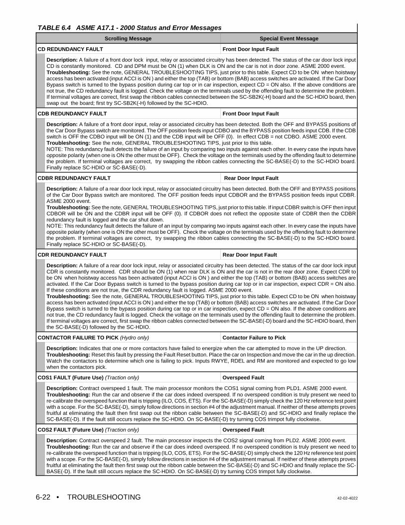
TABLE 6.4 ASME A17.1 - 2000 Status and Error Messages
Scrolling Message Special Event Message
• TROUBLESHOOTING 42-02-40226-22
CD REDUNDANCY FAULT Front Door Input Fault
Description: A failure of a front door lock input, relay or associated circuitry has been detected. The status of the car door lock inputCD is constantly monitored. CD and DPM must be ON (1) when DLK is ON and the car is not in door zone. ASME 2000 event.Troubleshooting: See the note, GENERAL TROUBLESHOOTING TIPS, just prior to this table. Expect CD to be ON when hoistwayaccess has been activated (input ACCI is ON ) and either the top (TAB) or bottom (BAB) access switches are activated. If the Car DoorBypass switch is turned to the bypass position during car top or in car inspection, expect CD = ON also. If the above conditions arenot true, the CD redundancy fault is logged. Check the voltage on the terminals used by the offending fault to determine the problem.If terminal voltages are correct, first swap the ribbon cables connected between the SC-SB2K(-H) board and the SC-HDIO board, thenswap out the board; first try SC-SB2K(-H) followed by the SC-HDIO.
CDB REDUNDANCY FAULT Front Door Input Fault
Description: A failure of a front door input, relay or associated circuitry has been detected. Both the OFF and BYPASS positions ofthe Car Door Bypass switch are monitored. The OFF position feeds input CDBO and the BYPASS position feeds input CDB. If the CDBswitch is OFF the CDBO input will be ON (1) and the CDB input will be OFF (0). In effect CDB = not CDBO. ASME 2000 event.Troubleshooting: See the note, GENERAL TROUBLESHOOTING TIPS, just prior to this table.NOTE: This redundancy fault detects the failure of an input by comparing two inputs against each other. In every case the inputs haveopposite polarity (when one is ON the other must be OFF). Check the voltage on the terminals used by the offending fault to determinethe problem. If terminal voltages are correct, try swapping the ribbon cables connecting the SC-BASE(-D) to the SC-HDIO board.Finally replace SC-HDIO or SC-BASE(-D).
CDBR REDUNDANCY FAULT Rear Door Input Fault
Description: A failure of a rear door lock input, relay or associated circuitry has been detected. Both the OFF and BYPASS positionsof the Car Door Bypass switch are monitored. The OFF position feeds input CDBOR and the BYPASS position feeds input CDBR.ASME 2000 event. Troubleshooting: See the note, GENERAL TROUBLESHOOTING TIPS, just prior to this table. If input CDBR switch is OFF then inputCDBOR will be ON and the CDBR input will be OFF (0). If CDBOR does not reflect the opposite state of CDBR then the CDBRredundancy fault is logged and the car shut down. NOTE: This redundancy fault detects the failure of an input by comparing two inputs against each other. In every case the inputs haveopposite polarity (when one is ON the other must be OFF). Check the voltage on the terminals used by the offending fault to determinethe problem. If terminal voltages are correct, try swapping the ribbon cables connecting the SC-BASE(-D) to the SC-HDIO board.Finally replace SC-HDIO or SC-BASE(-D).
CDR REDUNDANCY FAULT Rear Door Input Fault
Description: A failure of a rear door lock input, relay or associated circuitry has been detected. The status of the car door lock inputCDR is constantly monitored. CDR should be ON (1) when rear DLK is ON and the car is not in the rear door zone. Expect CDR tobe ON when hoistway access has been activated (input ACCI is ON ) and either the top (TAB) or bottom (BAB) access switches areactivated. If the Car Door Bypass switch is turned to the bypass position during car top or in car inspection, expect CDR = ON also.If these conditions are not true, the CDR redundancy fault is logged. ASME 2000 event.Troubleshooting: See the note, GENERAL TROUBLESHOOTING TIPS, just prior to this table. Expect CD to be ON when hoistwayaccess has been activated (input ACCI is ON ) and either the top (TAB) or bottom (BAB) access switches are activated. If the Car DoorBypass switch is turned to the bypass position during car top or in car inspection, expect CD = ON also. If the above conditions arenot true, the CD redundancy fault is logged. Check the voltage on the terminals used by the offending fault to determine the problem.If terminal voltages are correct, first swap the ribbon cables connected between the SC-BASE(-D) board and the SC-HDIO board, thenthe SC-BASE(-D) followed by the SC-HDIO.
CONTACTOR FAILURE TO PICK (Hydro only) Contactor Failure to Pick
Description: Indicates that one or more contactors have failed to energize when the car attempted to move in the UP direction.Troubleshooting: Reset this fault by pressing the Fault Reset button. Place the car on Inspection and move the car in the up direction.Watch the contactors to determine which one is failing to pick. Inputs RWYE, RDEL and RM are monitored and expected to go lowwhen the contactors pick.
COS1 FAULT (Future Use) (Traction only) Overspeed Fault
Description: Contract overspeed 1 fault. The main processor monitors the COS1 signal coming from PLD1. ASME 2000 event. Troubleshooting: Run the car and observe if the car does indeed overspeed. If no overspeed condition is truly present we need tore-calibrate the overspeed function that is tripping (ILO, COS, ETS). For the SC-BASE(-D) simply check the 120 Hz reference test pointwith a scope. For the SC-BASE(-D), simply follow directions in section #4 of the adjustment manual. If neither of these attempts provesfruitful at eliminating the fault then first swap out the ribbon cable between the SC-BASE(-D) and SC-HDIO and finally replace theSC-BASE(-D). If the fault still occurs replace the SC-HDIO. On SC-BASE(-D) try turning COS trimpot fully clockwise.
COS2 FAULT (Future Use) (Traction only) Overspeed Fault
Description: Contract overspeed 2 fault. The main processor inspects the COS2 signal coming from PLD2. ASME 2000 event.Troubleshooting: Run the car and observe if the car does indeed overspeed. If no overspeed condition is truly present we need tore-calibrate the overspeed function that is tripping (ILO, COS, ETS). For the SC-BASE(-D) simply check the 120 Hz reference test pointwith a scope. For the SC-BASE(-D), simply follow directions in section #4 of the adjustment manual. If neither of these attempts provesfruitful at eliminating the fault then first swap out the ribbon cable between the SC-BASE(-D) and SC-HDIO and finally replace the SC-BASE(-D). If the fault still occurs replace the SC-HDIO. On SC-BASE(-D) try turning COS trimpot fully clockwise.
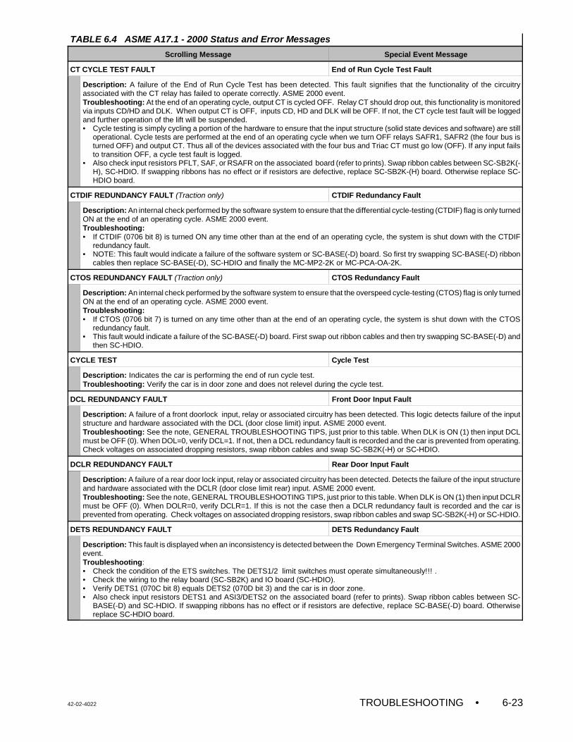
TABLE 6.4 ASME A17.1 - 2000 Status and Error Messages
Scrolling Message Special Event Message
42-02-4022 TROUBLESHOOTING • 6-23
CT CYCLE TEST FAULT End of Run Cycle Test Fault
Description: A failure of the End of Run Cycle Test has been detected. This fault signifies that the functionality of the circuitryassociated with the CT relay has failed to operate correctly. ASME 2000 event. Troubleshooting: At the end of an operating cycle, output CT is cycled OFF. Relay CT should drop out, this functionality is monitoredvia inputs CD/HD and DLK. When output CT is OFF, inputs CD, HD and DLK will be OFF. If not, the CT cycle test fault will be loggedand further operation of the lift will be suspended.• Cycle testing is simply cycling a portion of the hardware to ensure that the input structure (solid state devices and software) are still
operational. Cycle tests are performed at the end of an operating cycle when we turn OFF relays SAFR1, SAFR2 (the four bus isturned OFF) and output CT. Thus all of the devices associated with the four bus and Triac CT must go low (OFF). If any input failsto transition OFF, a cycle test fault is logged.
• Also check input resistors PFLT, SAF, or RSAFR on the associated board (refer to prints). Swap ribbon cables between SC-SB2K(-H), SC-HDIO. If swapping ribbons has no effect or if resistors are defective, replace SC-SB2K-(H) board. Otherwise replace SC-HDIO board.
CTDIF REDUNDANCY FAULT (Traction only) CTDIF Redundancy Fault
Description: An internal check performed by the software system to ensure that the differential cycle-testing (CTDIF) flag is only turnedON at the end of an operating cycle. ASME 2000 event.Troubleshooting: • If CTDIF (0706 bit 8) is turned ON any time other than at the end of an operating cycle, the system is shut down with the CTDIF
redundancy fault.• NOTE: This fault would indicate a failure of the software system or SC-BASE(-D) board. So first try swapping SC-BASE(-D) ribbon
cables then replace SC-BASE(-D), SC-HDIO and finally the MC-MP2-2K or MC-PCA-OA-2K.
CTOS REDUNDANCY FAULT (Traction only) CTOS Redundancy Fault
Description: An internal check performed by the software system to ensure that the overspeed cycle-testing (CTOS) flag is only turnedON at the end of an operating cycle. ASME 2000 event.Troubleshooting: • If CTOS (0706 bit 7) is turned on any time other than at the end of an operating cycle, the system is shut down with the CTOS
redundancy fault.• This fault would indicate a failure of the SC-BASE(-D) board. First swap out ribbon cables and then try swapping SC-BASE(-D) and
then SC-HDIO.
CYCLE TEST Cycle Test
Description: Indicates the car is performing the end of run cycle test.Troubleshooting: Verify the car is in door zone and does not relevel during the cycle test.
DCL REDUNDANCY FAULT Front Door Input Fault
Description: A failure of a front doorlock input, relay or associated circuitry has been detected. This logic detects failure of the inputstructure and hardware associated with the DCL (door close limit) input. ASME 2000 event.Troubleshooting: See the note, GENERAL TROUBLESHOOTING TIPS, just prior to this table. When DLK is ON (1) then input DCLmust be OFF (0). When DOL=0, verify DCL=1. If not, then a DCL redundancy fault is recorded and the car is prevented from operating.Check voltages on associated dropping resistors, swap ribbon cables and swap SC-SB2K(-H) or SC-HDIO.
DCLR REDUNDANCY FAULT Rear Door Input Fault
Description: A failure of a rear door lock input, relay or associated circuitry has been detected. Detects the failure of the input structureand hardware associated with the DCLR (door close limit rear) input. ASME 2000 event. Troubleshooting: See the note, GENERAL TROUBLESHOOTING TIPS, just prior to this table. When DLK is ON (1) then input DCLRmust be OFF (0). When DOLR=0, verify DCLR=1. If this is not the case then a DCLR redundancy fault is recorded and the car isprevented from operating. Check voltages on associated dropping resistors, swap ribbon cables and swap SC-SB2K(-H) or SC-HDIO.
DETS REDUNDANCY FAULT DETS Redundancy Fault
Description: This fault is displayed when an inconsistency is detected between the Down Emergency Terminal Switches. ASME 2000event.Troubleshooting: • Check the condition of the ETS switches. The DETS1/2 limit switches must operate simultaneously!!! .• Check the wiring to the relay board (SC-SB2K) and IO board (SC-HDIO).• Verify DETS1 (070C bit 8) equals DETS2 (070D bit 3) and the car is in door zone.• Also check input resistors DETS1 and ASI3/DETS2 on the associated board (refer to prints). Swap ribbon cables between SC-
BASE(-D) and SC-HDIO. If swapping ribbons has no effect or if resistors are defective, replace SC-BASE(-D) board. Otherwisereplace SC-HDIO board.

TABLE 6.4 ASME A17.1 - 2000 Status and Error Messages
Scrolling Message Special Event Message
• TROUBLESHOOTING 42-02-40226-24
DFV REDUNDANCY FAULT (Hydro only)
Description: Input DFV checks the status of the down terminal speed reducing switches. We simply compare input DFV against inputDTSRL. IF DFV not equal to DTSRL we assert this fault. Hence these switches must open up simultaneously. ASME 2000 event.Troubleshooting: Check that the limit switches are opening within one second of each other as the car approaches the bottom terminallanding. If they are, then use diagnostics to determine the status of the inputs. Check voltage at top of associated input resistors onSC-SB2K-H. When the inputs are ON expect 5 VAC. When OFF expect 0 VAC. If this is not the case replace the SC-SB2K-H. Ifvoltages are good, swap associated ribbon cable and finally swap the SC-HDIO
Direction Input Fault (not scrolled, Event Calendar only) Direction Input Fault
Description: A failure of a direction related input, relay or associated circuitry has been detected. Look to the scrolling message to seewhich fault is active: RDN, DNS, UPDIR, UPS, RUP, DNDIR REDUNDANCY FAULT or UP / DOWN NORMAL LIMIT SWITCH OPEN.ASME 2000 event.Troubleshooting: Once the scrolling message is identified, look up that message in this table.
DLK REDUNDANCY FAULT DLK Redundancy Fault
Description: A failure of the DLK input or associated circuitry has been detected. ASME 2000 event.Troubleshooting Tips:• DLK should be high (28 bit 7) when we are leveling and in door zone [ DZ is high (20 bit 6) or DZR is high (10 bit 6) and either LU
(29 bit 3) or LD (29 bit 7)is high].• DLK should also be high when all of the car and hoistway door lock inputs are made active [CD is high (0704 bit 1) and HD is high
(0704 bit 2) and CDR is high (070B bit 1) and HDR is high (070B bit 2) ]. If DLK is ON and any of these other relationships are nottrue, the DLK redundancy fault is set and disables further operation of the lift. Note that DLK is high when either or both of the cardoor or hoistway door lock bypass functions are active.
• Also check input resistors DLK, DZR, CD, HD, CDR and HDR on the associated board (refer to prints). Swap ribbon cables betweenSC-SB2K(-H), SC-BASE(-D) and SC-HDIO. If swapping ribbons has no effect or if resistors are defective, replace SC-SB2K-(H) orSC-BASER(-D) (for DZR) board. Otherwise replace SC-HDIO board.
DNDIR REDUNDANCY FAULT Direction Input Fault
Description: A failure of a direction related input, relay or associated circuitry has been detected. Valid when SAF=1. Input DNDIRis created by the SC-BASE(-D) board and represents resolved direction from the speed sensor. Input DNDIR must always be theopposite of RDN. If the main processor detects that the resolved direction (DNDIR from BASE board) does not agree with the intendeddirection (RDN from MP2 / PCA), the system is shut down with the DNDIR redundancy fault. ASME 2000 event.Troubleshooting: See the note, GENERAL TROUBLESHOOTING TIPS, just prior to this table.• Verify that the UP LED on the SC-BASE(-D) is ON when car motion is up and OFF when car motion is down. If not, the speed
sensor is reversed (rotate the sensor 180 degrees with respect to the magnet). • Swap Ribbons, check 95 and 96 signals (0 to 55VDC) swap SC-BASE(-D) or SC-HDIO.
DNS REDUNDANCY FAULT Direction Input Fault
Description: A failure of a direction related input, relay or associated circuitry has been detected. Valid when SAF=1. Verifies that thedown sense input DNS is valid. ASME 2000 event. Troubleshooting: See the note, GENERAL TROUBLESHOOTING TIPS, just prior to this table. Once DLK is ON (1), if DNS is ON(1), then RDN must be OFF (0). Check associated input resistors, swap boards or ribbon cables to correct.
Door Zone Input Fault (not scrolled, Event Calendar only) Door Zone Input Fault
Description: A failure of a door zone related input, relay or associated circuitry has been detected. Look at the Swing PanelAlphanumeric Display to see which fault is active: DZX, DZRX, RDZ, RDZX, or RDZR REDUNDANCY FAULT. ASME 2000 event.Troubleshooting: Once the Swing Panel Alphanumeric Display fault is identified, find that particular fault in this table. See the note,GENERAL TROUBLESHOOTING TIPS, just prior to this table.
DOWN NORMAL LIMIT SWITCH OPEN Direction Input Fault
Description: A failure of a direction related input, relay or associated circuitry has been detected. A failure of a direction related input,relay or associated circuitry has been detected. If SAF=1 and DLK=1 and the car is below the Down Normal Limit Switch (DNL=0), thenthis status is displayed. ASME 2000 event.Troubleshooting: See the note, GENERAL TROUBLESHOOTING TIPS, just prior to this table. Verify SAF=1 and DLK=1 and movethe car above the Down Normal Limit (DNL=1). Car should never automatically travel on to this limit switch. Possibility that switch isnot far enough into terminal.. Please move limit switch.
DP SENSOR / DIFFERENTIAL FAULT (Traction only) DP Sensor / Differential Fault
Description: This fault indicates that one of the PLDs (on the SC-BASE/SC-BASER) has detected a count difference in the pulse signalgenerated from Speed Sensor and magnet mounted on the motor.Troubleshooting: Verify that for up direction travel, LEDS UP1 and UP2 turn ON, and for down direction, that LEDs DN1 and DN2turn ON. If not:• Verify that the sensor is 1/16" away from the magnet on the motor shaft. Also verify that the magnet assembly is perpendicular
to the sensor. • Check the shielded cable that connects sensor assembly to SC-BASE/R board. Swap the cable.• Replace the sensor, followed by the SC-BASE/R board. Otherwise replace SC-HDIO board.
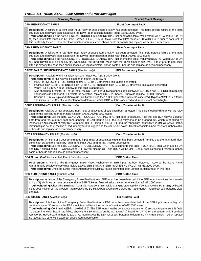
TABLE 6.4 ASME A17.1 - 2000 Status and Error Messages
Scrolling Message Special Event Message
42-02-4022 TROUBLESHOOTING • 6-25
DPM REDUNDANCY FAULT Front Door Input Fault
Description: A failure of a front door input, relay or associated circuitry has been detected. This logic detects failure of the inputstructure and hardware associated with the DPM (door position monitor) input. ASME 2000 event.Troubleshooting: See the note, GENERAL TROUBLESHOOTING TIPS, just prior to this table. Valid when SAF=1. When DLK is ON(1) then input DPM must also be ON (1). When DOL=0, DPM=0. Make sure that DPM makes (120 VAC) 1 to 2" prior to door lock. Ifthis is already the case then check associated input resistors, ribbon cable or boards and replace as deemed necessary.
DPMR REDUNDANCY FAULT Rear Door Input Fault
Description: A failure of a rear door input, relay or associated circuitry has been detected. This logic detects failure of the inputstructure and hardware associated with the DPMR (door position monitor rear) input. ASME 2000 event.Troubleshooting: See the note, GENERAL TROUBLESHOOTING TIPS, just prior to this table. Valid when SAF=1. When DLK is ON(1), input DPMR must also be ON (1). When DOLR=0, DPMR=0. Make sure that DPMR makes (120 VAC) 1 to 2" prior to door lock.If this is already the case then check associated input resistors, ribbon cable or boards and replace as deemed necessary.
DRIVE FAULT / REI REDUNDANCY FAULT (Traction only) REI Redundancy Fault
Description: A failure of the RE relay has been detected. ASME 2000 event.Troubleshooting: If FLT relay is picked, then check the following:• If SAF is low (2C bit 6), REI should be low (0707 bit 2), otherwise this fault is generated.• If UPS is high (24 bit 3) or DNS is high (24 bit 4), REI should be high (0707 bit 2), otherwise this fault is generated.• Verify REI = 0 (0707 bit 2), otherwise this fault is generated.• Also check input resistor REI at top left of the SC-SB2K board. Swap ribbon cables between SC-SB2K and SC-HDIO. If swapping
ribbons has no effect or if REI resistor is defective, replace SC-SB2K board. Otherwise replace SC-HDIO board.• Confirm FLT relay is picked when a run is initiated. If not, then a DDP generated failure has occurred. Bypass ASME A17.1 faults
and initiate a run. Check event calendar to determine which DDP fault has occurred and troubleshoot accordingly.
DZRX REDUNDANCY FAULT (Traction only) Door Zone Input Fault
Description: A failure of rear door zone input, relay or associated circuitry has been detected. This logic checks the integrity of the relayused for the auxiliary rear door zone function (DZX). ASME 2000 event.Troubleshooting: See the note, GENERAL TROUBLESHOOTING TIPS, just prior to this table. Note that one DZX relay is used forboth front and rear auxiliary door zone sensing. If DZR input is OFF, the DZX relay should be dropped out, which is checked byinspecting a NC contact of relay DZX with input RDZX. If input DZR is OFF and the “checking” input RDZX is ON, all is well. If thisrelationship is not true, the DZRX redundancy fault is logged and the car is shut down. Check associated input resistors, ribbon cableor boards and replace as deemed necessary.
DZX REDUNDANCY FAULT (Traction only) Door Zone Input Fault
Description: A failure of a door zone related input, relay or associated circuitry has been detected. Verifies that the “standard” doorzone input DZ and the “auxiliary” door zone input DZX both agree. ASME 2000 event.Troubleshooting: See the note, GENERAL TROUBLESHOOTING TIPS, just prior to this table. If DZX is ON, then DZ should be ONand RDZX should be OFF. When DZX = OFF, DZ will also be OFF and RDZX will be ON. Check associated input resistors, ribboncable or boards and replace as deemed necessary.
EBR Button Fault (not scrolled, Event Calendar only) EBR Button Fault
Description: A failure of the Emergency Brake Reset Pushbutton or EBR input has been detected. Look at the Swing PanelAlphanumeric Display to see what fault is active, EBR STUCK or EBR FLICKERING FAULT. ASME 2000 event.Troubleshooting: Once the Swing Panel Alphanumeric Display fault is identified, look up that particular fault in this table.
EBR FLICKERING FAULT (Traction only) EBR Button Fault
Description: A failure of the Emergency Brake Pushbutton or EBR input has been detected. If the EBR input transitions from low (0)to high (1) six times or more per second, the EBR flickering fault will take the car out of service. ASME 2000 event. Troubleshooting: Check the EBR input (0708 bit 3) and confirm that it is changing state rapidly. If so, replace the SC-BASE(-D) board.If this does not correct the problem, then replace the SC-HDIO board. Otherwise press the Redundancy Fault Reset pushbutton to clearthe fault.
EBR STUCK FAULT (Traction only) EBR Button Fault
Description: A failure of the Emergency Brake Pushbutton or EBR input has been detected. If the EBR input remains high (1)continuously for 30 seconds the EBR stuck fault will take the car out of service. ASME 2000 event.Troubleshooting: Confirm that EBR = 1 (0708 bit 3). The EBR input must be continuously active for 30 seconds to generate this fault.To determine which board has failed, check the EBR resistor on the SC-BASE(-D) board for 0 VAC on the bottom end, if so thenreplace SC-HDIO board. If there is 120 VAC, then inspect the EBR reset pushbutton and determine if it is truly stuck. If stuck replaceSC-BASE(-D), otherwise swap out associated ribbon cable.
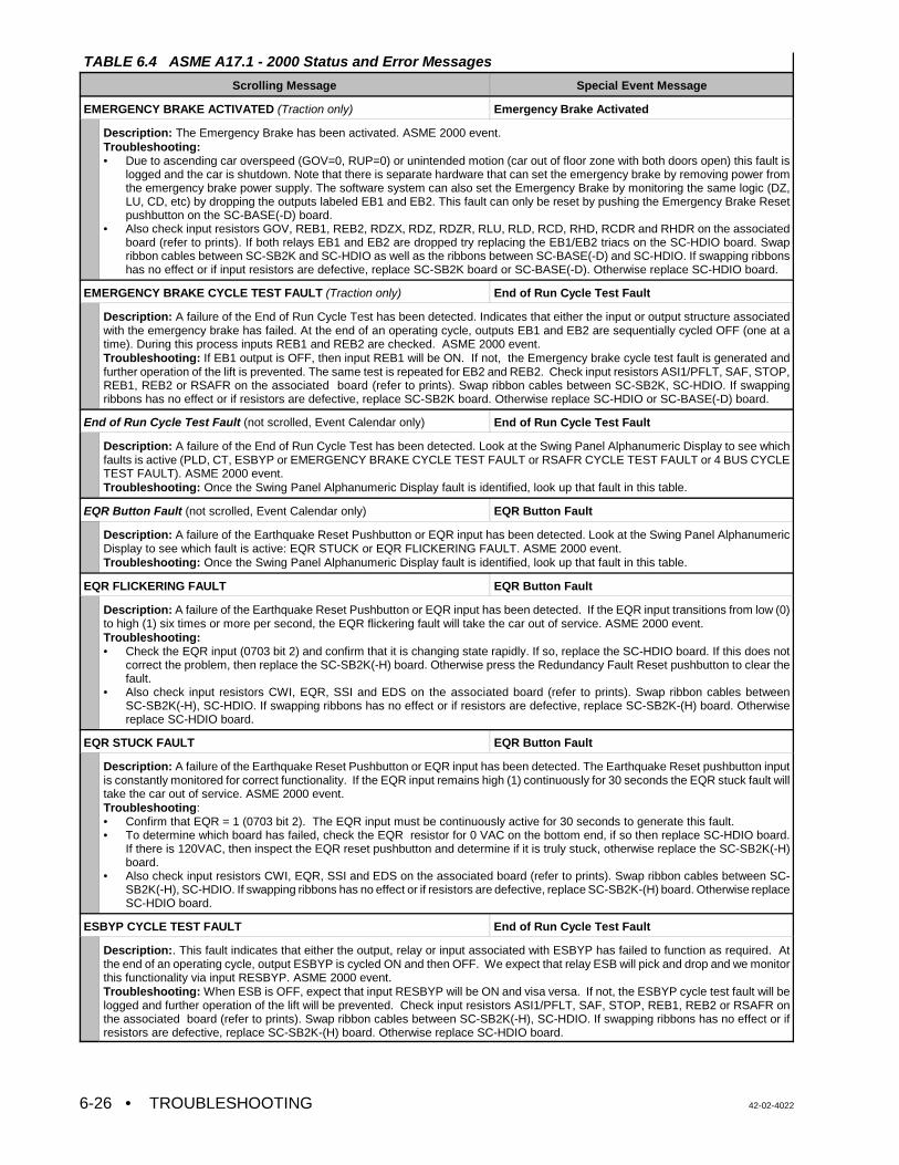
TABLE 6.4 ASME A17.1 - 2000 Status and Error Messages
Scrolling Message Special Event Message
• TROUBLESHOOTING 42-02-40226-26
EMERGENCY BRAKE ACTIVATED (Traction only) Emergency Brake Activated
Description: The Emergency Brake has been activated. ASME 2000 event.Troubleshooting:• Due to ascending car overspeed (GOV=0, RUP=0) or unintended motion (car out of floor zone with both doors open) this fault is
logged and the car is shutdown. Note that there is separate hardware that can set the emergency brake by removing power fromthe emergency brake power supply. The software system can also set the Emergency Brake by monitoring the same logic (DZ,LU, CD, etc) by dropping the outputs labeled EB1 and EB2. This fault can only be reset by pushing the Emergency Brake Resetpushbutton on the SC-BASE(-D) board.
• Also check input resistors GOV, REB1, REB2, RDZX, RDZ, RDZR, RLU, RLD, RCD, RHD, RCDR and RHDR on the associatedboard (refer to prints). If both relays EB1 and EB2 are dropped try replacing the EB1/EB2 triacs on the SC-HDIO board. Swapribbon cables between SC-SB2K and SC-HDIO as well as the ribbons between SC-BASE(-D) and SC-HDIO. If swapping ribbonshas no effect or if input resistors are defective, replace SC-SB2K board or SC-BASE(-D). Otherwise replace SC-HDIO board.
EMERGENCY BRAKE CYCLE TEST FAULT (Traction only) End of Run Cycle Test Fault
Description: A failure of the End of Run Cycle Test has been detected. Indicates that either the input or output structure associatedwith the emergency brake has failed. At the end of an operating cycle, outputs EB1 and EB2 are sequentially cycled OFF (one at atime). During this process inputs REB1 and REB2 are checked. ASME 2000 event.Troubleshooting: If EB1 output is OFF, then input REB1 will be ON. If not, the Emergency brake cycle test fault is generated andfurther operation of the lift is prevented. The same test is repeated for EB2 and REB2. Check input resistors ASI1/PFLT, SAF, STOP,REB1, REB2 or RSAFR on the associated board (refer to prints). Swap ribbon cables between SC-SB2K, SC-HDIO. If swappingribbons has no effect or if resistors are defective, replace SC-SB2K board. Otherwise replace SC-HDIO or SC-BASE(-D) board.
End of Run Cycle Test Fault (not scrolled, Event Calendar only) End of Run Cycle Test Fault
Description: A failure of the End of Run Cycle Test has been detected. Look at the Swing Panel Alphanumeric Display to see whichfaults is active (PLD, CT, ESBYP or EMERGENCY BRAKE CYCLE TEST FAULT or RSAFR CYCLE TEST FAULT or 4 BUS CYCLETEST FAULT). ASME 2000 event.Troubleshooting: Once the Swing Panel Alphanumeric Display fault is identified, look up that fault in this table.
EQR Button Fault (not scrolled, Event Calendar only) EQR Button Fault
Description: A failure of the Earthquake Reset Pushbutton or EQR input has been detected. Look at the Swing Panel AlphanumericDisplay to see which fault is active: EQR STUCK or EQR FLICKERING FAULT. ASME 2000 event.Troubleshooting: Once the Swing Panel Alphanumeric Display fault is identified, look up that fault in this table.
EQR FLICKERING FAULT EQR Button Fault
Description: A failure of the Earthquake Reset Pushbutton or EQR input has been detected. If the EQR input transitions from low (0)to high (1) six times or more per second, the EQR flickering fault will take the car out of service. ASME 2000 event.Troubleshooting:• Check the EQR input (0703 bit 2) and confirm that it is changing state rapidly. If so, replace the SC-HDIO board. If this does not
correct the problem, then replace the SC-SB2K(-H) board. Otherwise press the Redundancy Fault Reset pushbutton to clear thefault.
• Also check input resistors CWI, EQR, SSI and EDS on the associated board (refer to prints). Swap ribbon cables betweenSC-SB2K(-H), SC-HDIO. If swapping ribbons has no effect or if resistors are defective, replace SC-SB2K-(H) board. Otherwisereplace SC-HDIO board.
EQR STUCK FAULT EQR Button Fault
Description: A failure of the Earthquake Reset Pushbutton or EQR input has been detected. The Earthquake Reset pushbutton inputis constantly monitored for correct functionality. If the EQR input remains high (1) continuously for 30 seconds the EQR stuck fault willtake the car out of service. ASME 2000 event.Troubleshooting:• Confirm that EQR = 1 (0703 bit 2). The EQR input must be continuously active for 30 seconds to generate this fault.• To determine which board has failed, check the EQR resistor for 0 VAC on the bottom end, if so then replace SC-HDIO board.
If there is 120VAC, then inspect the EQR reset pushbutton and determine if it is truly stuck, otherwise replace the SC-SB2K(-H)board.
• Also check input resistors CWI, EQR, SSI and EDS on the associated board (refer to prints). Swap ribbon cables between SC-SB2K(-H), SC-HDIO. If swapping ribbons has no effect or if resistors are defective, replace SC-SB2K-(H) board. Otherwise replaceSC-HDIO board.
ESBYP CYCLE TEST FAULT End of Run Cycle Test Fault
Description:. This fault indicates that either the output, relay or input associated with ESBYP has failed to function as required. Atthe end of an operating cycle, output ESBYP is cycled ON and then OFF. We expect that relay ESB will pick and drop and we monitorthis functionality via input RESBYP. ASME 2000 event.Troubleshooting: When ESB is OFF, expect that input RESBYP will be ON and visa versa. If not, the ESBYP cycle test fault will belogged and further operation of the lift will be prevented. Check input resistors ASI1/PFLT, SAF, STOP, REB1, REB2 or RSAFR onthe associated board (refer to prints). Swap ribbon cables between SC-SB2K(-H), SC-HDIO. If swapping ribbons has no effect or ifresistors are defective, replace SC-SB2K-(H) board. Otherwise replace SC-HDIO board.
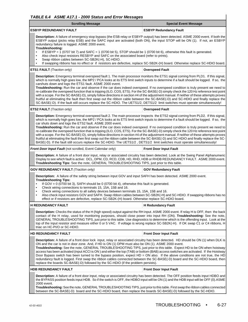
TABLE 6.4 ASME A17.1 - 2000 Status and Error Messages
Scrolling Message Special Event Message
42-02-4022 TROUBLESHOOTING • 6-27
ESBYP REDUNDANCY FAULT ESBYP Redundancy Fault
Description: A failure of emergency stop bypass (the ESB relay or ESBYP output) has been detected. ASME 2000 event. If both theESBYP output (picks relay ESB) and the SAFC input are activated (both ON), the input STOP will be ON (1). If not, an ESBYPredundancy failure is logged. ASME 2000 event.Troubleshooting: • If ESBYP = 1 (0707 bit 7) and SAFC = 1 (0700 bit 5), STOP should be 1 (0700 bit 6), otherwise this fault is generated.• Also check input resistors RESBYP and SAFC on the associated board (refer to prints). • Swap ribbon cables between SC-SB2K(-H), SC-HDIO.• If swapping ribbons has no effect or if resistors are defective, replace SC-SB2K-(H) board. Otherwise replace SC-HDIO board.
ETS1 FAULT (Traction only) Overspeed Fault
Description: Emergency terminal overspeed fault 1. The main processor monitors the ETS1 signal coming from PLD1. If this signal,which is normally high goes low, the MP2 / PCA looks at its ETS limit switch inputs to determine if a fault should be logged. If so, thecarshuts down and logs the ETS1 fault. ASME 2000 event.Troubleshooting: Run the car and observe if the car does indeed overspeed. If no overspeed condition is truly present we need tore-calibrate the overspeed function that is tripping (ILO, COS, ETS). For the SC-BASE(-D) simply check the 120 Hz reference test pointwith a scope. For the SC-BASE(-D), simply follow directions in section #4 of the adjustment manual. If neither of these attempts provesfruitful at eliminating the fault then first swap out the ribbon cable between the SC-BASE(-D) and SC-HDIO and finally replace theSC-BASE(-D). If the fault still occurs replace the SC-HDIO. The UETS1/2, DETS1/2 limit switches must operate simultaneously!
ETS2 FAULT (Traction only) Overspeed Fault
Description: Emergency terminal overspeed fault 2. The main processor inspects the ETS2 signal coming from PLD2. If this signal,which is normally high goes low, the MP2 / PCA looks at its ETS limit switch inputs to determine if a fault should be logged. If so, thecar shuts down and logs the ETS2 fault. ASME 2000 event.Troubleshooting: Run the car and observe if the car does indeed overspeed. If no overspeed condition is truly present we need tore-calibrate the overspeed function that is tripping (ILO, COS, ETS). For the SC-BASE(-D) simply check the 120 Hz reference test pointwith a scope. For the SC-BASE(-D), simply follow directions in section #4 of the adjustment manual. If neither of these attempts provesfruitful at eliminating the fault then first swap out the ribbon cable between the SC-BASE(-D) and SC-HDIO and finally replace the SC-BASE(-D). If the fault still occurs replace the SC-HDIO. The UETS1/2 , DETS1/2 limit switches must operate simultaneously!
Front Door Input Fault (not scrolled, Event Calendar only) Front Door Input Fault
Description: A failure of a front door input, relay or associated circuitry has been detected. Look at the Swing Panel AlphanumericDisplay to see which fault is active: DCL, DPM, CD, RCD, CDB, HD, RHD, HDB or RHDB REDUNDANCY FAULT. ASME 2000 event.Troubleshooting Tips: See the note, GENERAL TROUBLESHOOTING TIPS, just prior to this table.
GOV REDUNDANCY FAULT (Traction only) GOV Redundancy Fault
Description: A failure of the safety string between input GOV and input SAFH has been detected. ASME 2000 event.Troubleshooting Tips:• If GOV = 0 (0700 bit 3), SAFH should be 0 (0700 bit 4), otherwise this fault is generated.• Check wiring connections to terminals 15, 15A, 15B and 16.• Check wiring connections to all safety devices between terminals 15, 15A, 15B and 16. • Also check input resistors GOV and SAFH. Swap ribbon cables between SC-SB2K(-H) and SC-HDIO. If swapping ribbons has no
effect or if resistors are defective, replace SC-SB2K-(H) board. Otherwise replace SC-HDIO board.
H REDUNDANCY FAULT H Redundancy Fault
Description: Checks the status of the H (high speed) output against the RH input. ASME 2000 event. If relay H is OFF, then the backcontact of the H relay, used for monitoring purposes, should close power into input RH (ON). Troubleshooting: See the note,GENERAL TROUBLESHOOTING TIPS, just prior to this table. Use diagnostics to determine which is the offending input. Look at thetop of the input resistor and measure either 0 or 5 VAC. If voltage is wrong replace SC-SB2K(-H). If OK swap C1 or C4 ribbons, Htriac on HC-PI/O or SC-HDIO.
HD REDUNDANCY FAULT Front Door Input Fault
Description: A failure of a front door lock input, relay or associated circuitry has been detected. HD should be ON (1) when DLK isON and the car is not in door zone. And, if HD is ON (1) DPM must also be ON (1). ASME 2000 event.Troubleshooting: See the note, GENERAL TROUBLESHOOTING TIPS, just prior to this table. Expect HD to be ON when hoistwayaccess has been activated (input ACCI is ON ) and either the top (TAB) or bottom (BAB) access switches are activated. If the HoistwayDoor Bypass switch has been turned to the bypass position, expect HD = ON also. If the above conditions are not true, the HDredundancy fault is logged. First swap the ribbon cables connected between the SC-BASE(-D) board and the SC-HDIO board, thenreplace the boards SC-BASE(-D) followed by the SC-HDIO (if the problem persists).
HDB REDUNDANCY FAULT Front Door Input Fault
Description: A failure of a front door input, relay or associated circuitry has been detected. The OFF position feeds input HDBO andthe BYPASS position feeds input HDB. So if the switch is OFF, the HDBO input will be ON (1) and the HDB input will be OFF (0).ASME2000 event.Troubleshooting: See the note, GENERAL TROUBLESHOOTING TIPS, just prior to this table. First swap the ribbon cables connectedbetween the SC-BASE(-D) board and the SC-HDIO board, then replace the boards SC-BASE(-D) followed by the SC-HDIO.
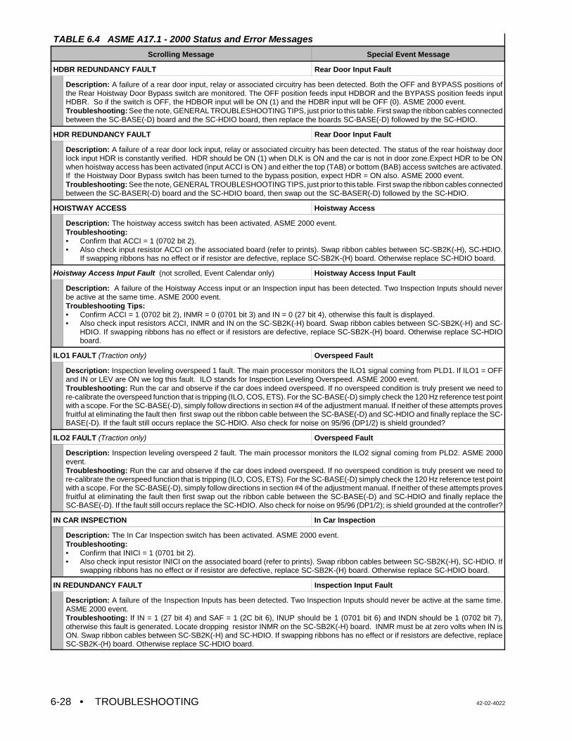
TABLE 6.4 ASME A17.1 - 2000 Status and Error Messages
Scrolling Message Special Event Message
• TROUBLESHOOTING 42-02-40226-28
HDBR REDUNDANCY FAULT Rear Door Input Fault
Description: A failure of a rear door input, relay or associated circuitry has been detected. Both the OFF and BYPASS positions ofthe Rear Hoistway Door Bypass switch are monitored. The OFF position feeds input HDBOR and the BYPASS position feeds inputHDBR. So if the switch is OFF, the HDBOR input will be ON (1) and the HDBR input will be OFF (0). ASME 2000 event.Troubleshooting: See the note, GENERAL TROUBLESHOOTING TIPS, just prior to this table. First swap the ribbon cables connectedbetween the SC-BASE(-D) board and the SC-HDIO board, then replace the boards SC-BASE(-D) followed by the SC-HDIO.
HDR REDUNDANCY FAULT Rear Door Input Fault
Description: A failure of a rear door lock input, relay or associated circuitry has been detected. The status of the rear hoistway doorlock input HDR is constantly verified. HDR should be ON (1) when DLK is ON and the car is not in door zone.Expect HDR to be ONwhen hoistway access has been activated (input ACCI is ON ) and either the top (TAB) or bottom (BAB) access switches are activated.If the Hoistway Door Bypass switch has been turned to the bypass position, expect HDR = ON also. ASME 2000 event. Troubleshooting: See the note, GENERAL TROUBLESHOOTING TIPS, just prior to this table. First swap the ribbon cables connectedbetween the SC-BASER(-D) board and the SC-HDIO board, then swap out the SC-BASER(-D) followed by the SC-HDIO.
HOISTWAY ACCESS Hoistway Access
Description: The hoistway access switch has been activated. ASME 2000 event.Troubleshooting: • Confirm that ACCI = 1 (0702 bit 2).• Also check input resistor ACCI on the associated board (refer to prints). Swap ribbon cables between SC-SB2K(-H), SC-HDIO.
If swapping ribbons has no effect or if resistor are defective, replace SC-SB2K-(H) board. Otherwise replace SC-HDIO board.
Hoistway Access Input Fault (not scrolled, Event Calendar only) Hoistway Access Input Fault
Description: A failure of the Hoistway Access input or an Inspection input has been detected. Two Inspection Inputs should neverbe active at the same time. ASME 2000 event.Troubleshooting Tips:• Confirm ACCI = 1 (0702 bit 2), INMR = 0 (0701 bit 3) and IN = 0 (27 bit 4), otherwise this fault is displayed.• Also check input resistors ACCI, INMR and IN on the SC-SB2K(-H) board. Swap ribbon cables between SC-SB2K(-H) and SC-
HDIO. If swapping ribbons has no effect or if resistors are defective, replace SC-SB2K-(H) board. Otherwise replace SC-HDIOboard.
ILO1 FAULT (Traction only) Overspeed Fault
Description: Inspection leveling overspeed 1 fault. The main processor monitors the ILO1 signal coming from PLD1. If ILO1 = OFFand IN or LEV are ON we log this fault. ILO stands for Inspection Leveling Overspeed. ASME 2000 event.Troubleshooting: Run the car and observe if the car does indeed overspeed. If no overspeed condition is truly present we need tore-calibrate the overspeed function that is tripping (ILO, COS, ETS). For the SC-BASE(-D) simply check the 120 Hz reference test pointwith a scope. For the SC-BASE(-D), simply follow directions in section #4 of the adjustment manual. If neither of these attempts provesfruitful at eliminating the fault then first swap out the ribbon cable between the SC-BASE(-D) and SC-HDIO and finally replace the SC-BASE(-D). If the fault still occurs replace the SC-HDIO. Also check for noise on 95/96 (DP1/2) is shield grounded?
ILO2 FAULT (Traction only) Overspeed Fault
Description: Inspection leveling overspeed 2 fault. The main processor monitors the ILO2 signal coming from PLD2. ASME 2000event.Troubleshooting: Run the car and observe if the car does indeed overspeed. If no overspeed condition is truly present we need tore-calibrate the overspeed function that is tripping (ILO, COS, ETS). For the SC-BASE(-D) simply check the 120 Hz reference test pointwith a scope. For the SC-BASE(-D), simply follow directions in section #4 of the adjustment manual. If neither of these attempts provesfruitful at eliminating the fault then first swap out the ribbon cable between the SC-BASE(-D) and SC-HDIO and finally replace theSC-BASE(-D). If the fault still occurs replace the SC-HDIO. Also check for noise on 95/96 (DP1/2); is shield grounded at the controller?
IN CAR INSPECTION In Car Inspection
Description: The In Car Inspection switch has been activated. ASME 2000 event.Troubleshooting:• Confirm that INICI = 1 (0701 bit 2).• Also check input resistor INICI on the associated board (refer to prints). Swap ribbon cables between SC-SB2K(-H), SC-HDIO. If
swapping ribbons has no effect or if resistor are defective, replace SC-SB2K-(H) board. Otherwise replace SC-HDIO board.
IN REDUNDANCY FAULT Inspection Input Fault
Description: A failure of the Inspection Inputs has been detected. Two Inspection Inputs should never be active at the same time.ASME 2000 event.Troubleshooting: If IN = 1 (27 bit 4) and SAF = 1 (2C bit 6), INUP should be 1 (0701 bit 6) and INDN should be 1 (0702 bit 7),otherwise this fault is generated. Locate dropping resistor INMR on the SC-SB2K(-H) board. INMR must be at zero volts when IN isON. Swap ribbon cables between SC-SB2K(-H) and SC-HDIO. If swapping ribbons has no effect or if resistors are defective, replaceSC-SB2K-(H) board. Otherwise replace SC-HDIO board.
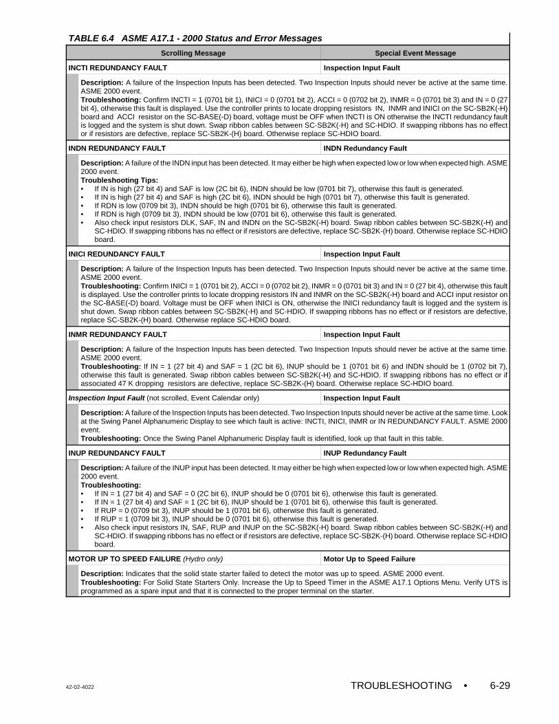
TABLE 6.4 ASME A17.1 - 2000 Status and Error Messages
Scrolling Message Special Event Message
42-02-4022 TROUBLESHOOTING • 6-29
INCTI REDUNDANCY FAULT Inspection Input Fault
Description: A failure of the Inspection Inputs has been detected. Two Inspection Inputs should never be active at the same time.ASME 2000 event.Troubleshooting: Confirm INCTI = 1 (0701 bit 1), INICI = 0 (0701 bit 2), ACCI = 0 (0702 bit 2), INMR = 0 (0701 bit 3) and IN = 0 (27bit 4), otherwise this fault is displayed. Use the controller prints to locate dropping resistors IN, INMR and INICI on the SC-SB2K(-H)board and ACCI resistor on the SC-BASE(-D) board, voltage must be OFF when INCTI is ON otherwise the INCTI redundancy faultis logged and the system is shut down. Swap ribbon cables between SC-SB2K(-H) and SC-HDIO. If swapping ribbons has no effector if resistors are defective, replace SC-SB2K-(H) board. Otherwise replace SC-HDIO board.
INDN REDUNDANCY FAULT INDN Redundancy Fault
Description: A failure of the INDN input has been detected. It may either be high when expected low or low when expected high. ASME2000 event.Troubleshooting Tips:• If IN is high (27 bit 4) and SAF is low (2C bit 6), INDN should be low (0701 bit 7), otherwise this fault is generated.• If IN is high (27 bit 4) and SAF is high (2C bit 6), INDN should be high (0701 bit 7), otherwise this fault is generated.• If RDN is low (0709 bit 3), INDN should be high (0701 bit 6), otherwise this fault is generated.• If RDN is high (0709 bit 3), INDN should be low (0701 bit 6), otherwise this fault is generated.• Also check input resistors DLK, SAF, IN and INDN on the SC-SB2K(-H) board. Swap ribbon cables between SC-SB2K(-H) and
SC-HDIO. If swapping ribbons has no effect or if resistors are defective, replace SC-SB2K-(H) board. Otherwise replace SC-HDIOboard.
INICI REDUNDANCY FAULT Inspection Input Fault
Description: A failure of the Inspection Inputs has been detected. Two Inspection Inputs should never be active at the same time.ASME 2000 event.Troubleshooting: Confirm INICI = 1 (0701 bit 2), ACCI = 0 (0702 bit 2), INMR = 0 (0701 bit 3) and IN = 0 (27 bit 4), otherwise this faultis displayed. Use the controller prints to locate dropping resistors IN and INMR on the SC-SB2K(-H) board and ACCI input resistor onthe SC-BASE(-D) board. Voltage must be OFF when INICI is ON, otherwise the INICI redundancy fault is logged and the system isshut down. Swap ribbon cables between SC-SB2K(-H) and SC-HDIO. If swapping ribbons has no effect or if resistors are defective,replace SC-SB2K-(H) board. Otherwise replace SC-HDIO board.
INMR REDUNDANCY FAULT Inspection Input Fault
Description: A failure of the Inspection Inputs has been detected. Two Inspection Inputs should never be active at the same time.ASME 2000 event.Troubleshooting: If IN = 1 (27 bit 4) and SAF = 1 (2C bit 6), INUP should be 1 (0701 bit 6) and INDN should be 1 (0702 bit 7),otherwise this fault is generated. Swap ribbon cables between SC-SB2K(-H) and SC-HDIO. If swapping ribbons has no effect or ifassociated 47 K dropping resistors are defective, replace SC-SB2K-(H) board. Otherwise replace SC-HDIO board.
Inspection Input Fault (not scrolled, Event Calendar only) Inspection Input Fault
Description: A failure of the Inspection Inputs has been detected. Two Inspection Inputs should never be active at the same time. Lookat the Swing Panel Alphanumeric Display to see which fault is active: INCTI, INICI, INMR or IN REDUNDANCY FAULT. ASME 2000event.Troubleshooting: Once the Swing Panel Alphanumeric Display fault is identified, look up that fault in this table.
INUP REDUNDANCY FAULT INUP Redundancy Fault
Description: A failure of the INUP input has been detected. It may either be high when expected low or low when expected high. ASME2000 event.Troubleshooting:• If IN = 1 (27 bit 4) and SAF = 0 (2C bit 6), INUP should be 0 (0701 bit 6), otherwise this fault is generated.• If IN = 1 (27 bit 4) and SAF = 1 (2C bit 6), INUP should be 1 (0701 bit 6), otherwise this fault is generated.• If RUP = 0 (0709 bit 3), INUP should be 1 (0701 bit 6), otherwise this fault is generated.• If RUP = 1 (0709 bit 3), INUP should be 0 (0701 bit 6), otherwise this fault is generated.• Also check input resistors IN, SAF, RUP and INUP on the SC-SB2K(-H) board. Swap ribbon cables between SC-SB2K(-H) and
SC-HDIO. If swapping ribbons has no effect or if resistors are defective, replace SC-SB2K-(H) board. Otherwise replace SC-HDIOboard.
MOTOR UP TO SPEED FAILURE (Hydro only) Motor Up to Speed Failure
Description: Indicates that the solid state starter failed to detect the motor was up to speed. ASME 2000 event.Troubleshooting: For Solid State Starters Only. Increase the Up to Speed Timer in the ASME A17.1 Options Menu. Verify UTS isprogrammed as a spare input and that it is connected to the proper terminal on the starter.
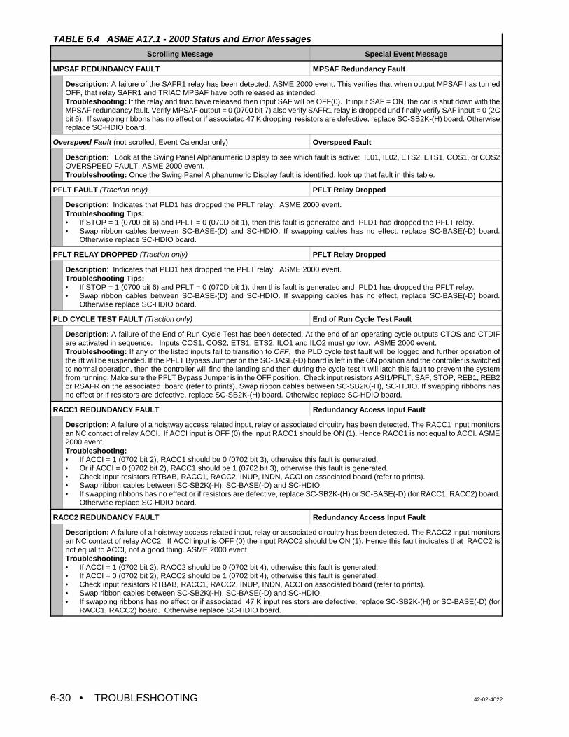
TABLE 6.4 ASME A17.1 - 2000 Status and Error Messages
Scrolling Message Special Event Message
• TROUBLESHOOTING 42-02-40226-30
MPSAF REDUNDANCY FAULT MPSAF Redundancy Fault
Description: A failure of the SAFR1 relay has been detected. ASME 2000 event. This verifies that when output MPSAF has turnedOFF, that relay SAFR1 and TRIAC MPSAF have both released as intended.Troubleshooting: If the relay and triac have released then input SAF will be OFF(0). If input SAF = ON, the car is shut down with theMPSAF redundancy fault. Verify MPSAF output = 0 (0700 bit 7) also verify SAFR1 relay is dropped und finally verify SAF input = 0 (2Cbit 6). If swapping ribbons has no effect or if associated 47 K dropping resistors are defective, replace SC-SB2K-(H) board. Otherwisereplace SC-HDIO board.
Overspeed Fault (not scrolled, Event Calendar only) Overspeed Fault
Description: Look at the Swing Panel Alphanumeric Display to see which fault is active: IL01, IL02, ETS2, ETS1, COS1, or COS2OVERSPEED FAULT. ASME 2000 event.Troubleshooting: Once the Swing Panel Alphanumeric Display fault is identified, look up that fault in this table.
PFLT FAULT (Traction only) PFLT Relay Dropped
Description: Indicates that PLD1 has dropped the PFLT relay. ASME 2000 event.Troubleshooting Tips:• If STOP = 1 (0700 bit 6) and PFLT = 0 (070D bit 1), then this fault is generated and PLD1 has dropped the PFLT relay.• Swap ribbon cables between SC-BASE-(D) and SC-HDIO. If swapping cables has no effect, replace SC-BASE(-D) board.
Otherwise replace SC-HDIO board.
PFLT RELAY DROPPED (Traction only) PFLT Relay Dropped
Description: Indicates that PLD1 has dropped the PFLT relay. ASME 2000 event.Troubleshooting Tips:• If STOP = 1 (0700 bit 6) and PFLT = 0 (070D bit 1), then this fault is generated and PLD1 has dropped the PFLT relay.• Swap ribbon cables between SC-BASE-(D) and SC-HDIO. If swapping cables has no effect, replace SC-BASE(-D) board.
Otherwise replace SC-HDIO board.
PLD CYCLE TEST FAULT (Traction only) End of Run Cycle Test Fault
Description: A failure of the End of Run Cycle Test has been detected. At the end of an operating cycle outputs CTOS and CTDIFare activated in sequence. Inputs COS1, COS2, ETS1, ETS2, ILO1 and ILO2 must go low. ASME 2000 event.Troubleshooting: If any of the listed inputs fail to transition to OFF, the PLD cycle test fault will be logged and further operation ofthe lift will be suspended. If the PFLT Bypass Jumper on the SC-BASE(-D) board is left in the ON position and the controller is switchedto normal operation, then the controller will find the landing and then during the cycle test it will latch this fault to prevent the systemfrom running. Make sure the PFLT Bypass Jumper is in the OFF position. Check input resistors ASI1/PFLT, SAF, STOP, REB1, REB2or RSAFR on the associated board (refer to prints). Swap ribbon cables between SC-SB2K(-H), SC-HDIO. If swapping ribbons hasno effect or if resistors are defective, replace SC-SB2K-(H) board. Otherwise replace SC-HDIO board.
RACC1 REDUNDANCY FAULT Redundancy Access Input Fault
Description: A failure of a hoistway access related input, relay or associated circuitry has been detected. The RACC1 input monitorsan NC contact of relay ACCI. If ACCI input is OFF (0) the input RACC1 should be ON (1). Hence RACC1 is not equal to ACCI. ASME2000 event.Troubleshooting: • If ACCI = 1 (0702 bit 2), RACC1 should be 0 (0702 bit 3), otherwise this fault is generated.• Or if ACCI = 0 (0702 bit 2), RACC1 should be 1 (0702 bit 3), otherwise this fault is generated.• Check input resistors RTBAB, RACC1, RACC2, INUP, INDN, ACCI on associated board (refer to prints). • Swap ribbon cables between SC-SB2K(-H), SC-BASE(-D) and SC-HDIO. • If swapping ribbons has no effect or if resistors are defective, replace SC-SB2K-(H) or SC-BASE(-D) (for RACC1, RACC2) board.
Otherwise replace SC-HDIO board.
RACC2 REDUNDANCY FAULT Redundancy Access Input Fault
Description: A failure of a hoistway access related input, relay or associated circuitry has been detected. The RACC2 input monitorsan NC contact of relay ACC2. If ACCI input is OFF (0) the input RACC2 should be ON (1). Hence this fault indicates that RACC2 isnot equal to ACCI, not a good thing. ASME 2000 event.Troubleshooting: • If ACCI = 1 (0702 bit 2), RACC2 should be 0 (0702 bit 4), otherwise this fault is generated.• If ACCI = 0 (0702 bit 2), RACC2 should be 1 (0702 bit 4), otherwise this fault is generated.• Check input resistors RTBAB, RACC1, RACC2, INUP, INDN, ACCI on associated board (refer to prints). • Swap ribbon cables between SC-SB2K(-H), SC-BASE(-D) and SC-HDIO. • If swapping ribbons has no effect or if associated 47 K input resistors are defective, replace SC-SB2K-(H) or SC-BASE(-D) (for
RACC1, RACC2) board. Otherwise replace SC-HDIO board.
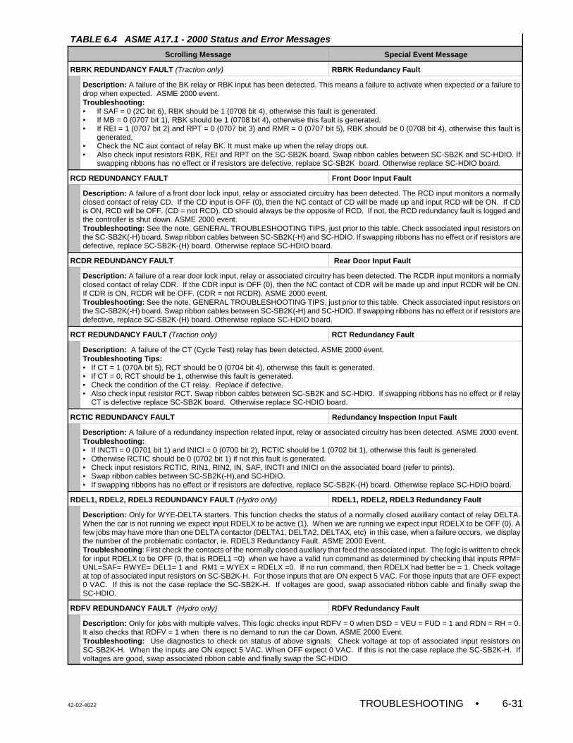
TABLE 6.4 ASME A17.1 - 2000 Status and Error Messages
Scrolling Message Special Event Message
42-02-4022 TROUBLESHOOTING • 6-31
RBRK REDUNDANCY FAULT (Traction only) RBRK Redundancy Fault
Description: A failure of the BK relay or RBK input has been detected. This means a failure to activate when expected or a failure todrop when expected. ASME 2000 event.Troubleshooting:• If SAF = 0 (2C bit 6), RBK should be 1 (0708 bit 4), otherwise this fault is generated.• If MB = 0 (0707 bit 1), RBK should be 1 (0708 bit 4), otherwise this fault is generated.• If REI = 1 (0707 bit 2) and RPT = 0 (0707 bit 3) and RMR = 0 (0707 bit 5), RBK should be 0 (0708 bit 4), otherwise this fault is
generated.• Check the NC aux contact of relay BK. It must make up when the relay drops out.• Also check input resistors RBK, REI and RPT on the SC-SB2K board. Swap ribbon cables between SC-SB2K and SC-HDIO. If
swapping ribbons has no effect or if resistors are defective, replace SC-SB2K board. Otherwise replace SC-HDIO board.
RCD REDUNDANCY FAULT Front Door Input Fault
Description: A failure of a front door lock input, relay or associated circuitry has been detected. The RCD input monitors a normallyclosed contact of relay CD. If the CD input is OFF (0), then the NC contact of CD will be made up and input RCD will be ON. If CDis ON, RCD will be OFF. (CD = not RCD). CD should always be the opposite of RCD. If not, the RCD redundancy fault is logged andthe controller is shut down. ASME 2000 event.Troubleshooting: See the note, GENERAL TROUBLESHOOTING TIPS, just prior to this table. Check associated input resistors onthe SC-SB2K(-H) board. Swap ribbon cables between SC-SB2K(-H) and SC-HDIO. If swapping ribbons has no effect or if resistors aredefective, replace SC-SB2K-(H) board. Otherwise replace SC-HDIO board.
RCDR REDUNDANCY FAULT Rear Door Input Fault
Description: A failure of a rear door lock input, relay or associated circuitry has been detected. The RCDR input monitors a normallyclosed contact of relay CDR. If the CDR input is OFF (0), then the NC contact of CDR will be made up and input RCDR will be ON.If CDR is ON, RCDR will be OFF. (CDR = not RCDR). ASME 2000 event.Troubleshooting: See the note, GENERAL TROUBLESHOOTING TIPS, just prior to this table. Check associated input resistors onthe SC-SB2K(-H) board. Swap ribbon cables between SC-SB2K(-H) and SC-HDIO. If swapping ribbons has no effect or if resistors aredefective, replace SC-SB2K-(H) board. Otherwise replace SC-HDIO board.
RCT REDUNDANCY FAULT (Traction only) RCT Redundancy Fault
Description: A failure of the CT (Cycle Test) relay has been detected. ASME 2000 event.Troubleshooting Tips:• If CT = 1 (070A bit 5), RCT should be 0 (0704 bit 4), otherwise this fault is generated.• If CT = 0, RCT should be 1, otherwise this fault is generated.• Check the condition of the CT relay. Replace if defective.• Also check input resistor RCT. Swap ribbon cables between SC-SB2K and SC-HDIO. If swapping ribbons has no effect or if relay
CT is defective replace SC-SB2K board. Otherwise replace SC-HDIO board.
RCTIC REDUNDANCY FAULT Redundancy Inspection Input Fault
Description: A failure of a redundancy inspection related input, relay or associated circuitry has been detected. ASME 2000 event.Troubleshooting: • If INCTI = 0 (0701 bit 1) and INICI = 0 (0700 bit 2), RCTIC should be 1 (0702 bit 1), otherwise this fault is generated.• Otherwise RCTIC should be 0 (0702 bit 1) if not this fault is generated.• Check input resistors RCTIC, RIN1, RIN2, IN, SAF, INCTI and INICI on the associated board (refer to prints). • Swap ribbon cables between SC-SB2K(-H),and SC-HDIO.• If swapping ribbons has no effect or if resistors are defective, replace SC-SB2K-(H) board. Otherwise replace SC-HDIO board.
RDEL1, RDEL2, RDEL3 REDUNDANCY FAULT (Hydro only) RDEL1, RDEL2, RDEL3 Redundancy Fault
Description: Only for WYE-DELTA starters. This function checks the status of a normally closed auxiliary contact of relay DELTA.When the car is not running we expect input RDELX to be active (1). When we are running we expect input RDELX to be OFF (0). Afew jobs may have more than one DELTA contactor (DELTA1, DELTA2, DELTAX, etc) in this case, when a failure occurs, we displaythe number of the problematic contactor, ie. RDEL3 Redundancy Fault. ASME 2000 Event.Troubleshooting: First check the contacts of the normally closed auxiliary that feed the associated input. The logic is written to checkfor input RDELX to be OFF (0, that is RDEL1 =0) when we have a valid run command as determined by checking that inputs RPM=UNL=SAF= RWYE= DEL1= 1 and RM1 = WYEX = RDELX =0. If no run command, then RDELX had better be = 1. Check voltageat top of associated input resistors on SC-SB2K-H. For those inputs that are ON expect 5 VAC. For those inputs that are OFF expect0 VAC. If this is not the case replace the SC-SB2K-H. If voltages are good, swap associated ribbon cable and finally swap theSC-HDIO.
RDFV REDUNDANCY FAULT (Hydro only) RDFV Redundancy Fault
Description: Only for jobs with multiple valves. This logic checks input RDFV = 0 when DSD = VEU = FUD = 1 and RDN = RH = 0.It also checks that RDFV = 1 when there is no demand to run the car Down. ASME 2000 Event.Troubleshooting: Use diagnostics to check on status of above signals. Check voltage at top of associated input resistors onSC-SB2K-H. When the inputs are ON expect 5 VAC. When OFF expect 0 VAC. If this is not the case replace the SC-SB2K-H. Ifvoltages are good, swap associated ribbon cable and finally swap the SC-HDIO
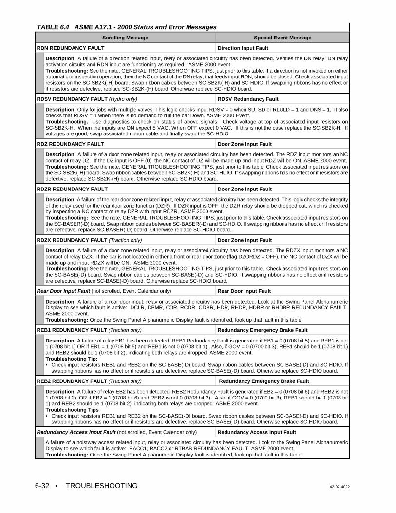
TABLE 6.4 ASME A17.1 - 2000 Status and Error Messages
Scrolling Message Special Event Message
• TROUBLESHOOTING 42-02-40226-32
RDN REDUNDANCY FAULT Direction Input Fault
Description: A failure of a direction related input, relay or associated circuitry has been detected. Verifies the DN relay, DN relayactivation circuits and RDN input are functioning as required. ASME 2000 event.Troubleshooting: See the note, GENERAL TROUBLESHOOTING TIPS, just prior to this table. If a direction is not invoked on eitherautomatic or inspection operation, then the NC contact of the DN relay, that feeds input RDN, should be closed. Check associated inputresistors on the SC-SB2K(-H) board. Swap ribbon cables between SC-SB2K(-H) and SC-HDIO. If swapping ribbons has no effect orif resistors are defective, replace SC-SB2K-(H) board. Otherwise replace SC-HDIO board.
RDSV REDUNDANCY FAULT (Hydro only) RDSV Redundancy Fault
Description: Only for jobs with multiple valves. This logic checks input RDSV = 0 when SU, SD or RLULD = 1 and DNS = 1. It alsochecks that RDSV = 1 when there is no demand to run the car Down. ASME 2000 Event. Troubleshooting. Use diagnostics to check on status of above signals. Check voltage at top of associated input resistors onSC-SB2K-H. When the inputs are ON expect 5 VAC. When OFF expect 0 VAC. If this is not the case replace the SC-SB2K-H. Ifvoltages are good, swap associated ribbon cable and finally swap the SC-HDIO
RDZ REDUNDANCY FAULT Door Zone Input Fault
Description: A failure of a door zone related input, relay or associated circuitry has been detected. The RDZ input monitors an NCcontact of relay DZ. If the DZ input is OFF (0), the NC contact of DZ will be made up and input RDZ will be ON. ASME 2000 event.Troubleshooting: See the note, GENERAL TROUBLESHOOTING TIPS, just prior to this table. Check associated input resistors onthe SC-SB2K(-H) board. Swap ribbon cables between SC-SB2K(-H) and SC-HDIO. If swapping ribbons has no effect or if resistors aredefective, replace SC-SB2K-(H) board. Otherwise replace SC-HDIO board.
RDZR REDUNDANCY FAULT Door Zone Input Fault
Description: A failure of the rear door zone related input, relay or associated circuitry has been detected. This logic checks the integrityof the relay used for the rear door zone function (DZR). If DZR input is OFF, the DZR relay should be dropped out, which is checkedby inspecting a NC contact of relay DZR with input RDZR. ASME 2000 event. Troubleshooting: See the note, GENERAL TROUBLESHOOTING TIPS, just prior to this table. Check associated input resistors onthe SC-BASER(-D) board. Swap ribbon cables between SC-BASER(-D) and SC-HDIO. If swapping ribbons has no effect or if resistorsare defective, replace SC-BASER(-D) board. Otherwise replace SC-HDIO board.
RDZX REDUNDANCY FAULT (Traction only) Door Zone Input Fault
Description: A failure of a door zone related input, relay or associated circuitry has been detected. The RDZX input monitors a NCcontact of relay DZX. If the car is not located in either a front or rear door zone (flag DZORDZ = OFF), the NC contact of DZX will bemade up and input RDZX will be ON. ASME 2000 event.Troubleshooting: See the note, GENERAL TROUBLESHOOTING TIPS, just prior to this table. Check associated input resistors onthe SC-BASE(-D) board. Swap ribbon cables between SC-BASE(-D) and SC-HDIO. If swapping ribbons has no effect or if resistorsare defective, replace SC-BASE(-D) board. Otherwise replace SC-HDIO board.
Rear Door Input Fault (not scrolled, Event Calendar only) Rear Door Input Fault
Description: A failure of a rear door input, relay or associated circuitry has been detected. Look at the Swing Panel AlphanumericDisplay to see which fault is active: DCLR, DPMR, CDR, RCDR, CDBR, HDR, RHDR, HDBR or RHDBR REDUNDANCY FAULT.ASME 2000 event.Troubleshooting: Once the Swing Panel Alphanumeric Display fault is identified, look up that fault in this table.
REB1 REDUNDANCY FAULT (Traction only) Redundancy Emergency Brake Fault
Description: A failure of relay EB1 has been detected. REB1 Redundancy Fault is generated if EB1 = 0 (0708 bit 5) and REB1 is not1 (0708 bit 1) OR if EB1 = 1 (0708 bit 5) and REB1 is not 0 (0708 bit 1). Also, if GOV = 0 (0700 bit 3), REB1 should be 1 (0708 bit 1)and REB2 should be 1 (0708 bit 2), indicating both relays are dropped. ASME 2000 event.Troubleshooting Tip:• Check input resistors REB1 and REB2 on the SC-BASE(-D) board. Swap ribbon cables between SC-BASE(-D) and SC-HDIO. If
swapping ribbons has no effect or if resistors are defective, replace SC-BASE(-D) board. Otherwise replace SC-HDIO board.
REB2 REDUNDANCY FAULT (Traction only) Redundancy Emergency Brake Fault
Description: A failure of relay EB2 has been detected. REB2 Redundancy Fault is generated if EB2 = 0 (0708 bit 6) and REB2 is not1 (0708 bit 2) OR if EB2 = 1 (0708 bit 6) and REB2 is not 0 (0708 bit 2). Also, if GOV = 0 (0700 bit 3), REB1 should be 1 (0708 bit1) and REB2 should be 1 (0708 bit 2), indicating both relays are dropped. ASME 2000 event.Troubleshooting Tips• Check input resistors REB1 and REB2 on the SC-BASE(-D) board. Swap ribbon cables between SC-BASE(-D) and SC-HDIO. If
swapping ribbons has no effect or if resistors are defective, replace SC-BASE(-D) board. Otherwise replace SC-HDIO board.
Redundancy Access Input Fault (not scrolled, Event Calendar only) Redundancy Access Input Fault
A failure of a hoistway access related input, relay or associated circuitry has been detected. Look to the Swing Panel AlphanumericDisplay to see which fault is active: RACC1, RACC2 or RTBAB REDUNDANCY FAULT. ASME 2000 event.Troubleshooting: Once the Swing Panel Alphanumeric Display fault is identified, look up that fault in this table.
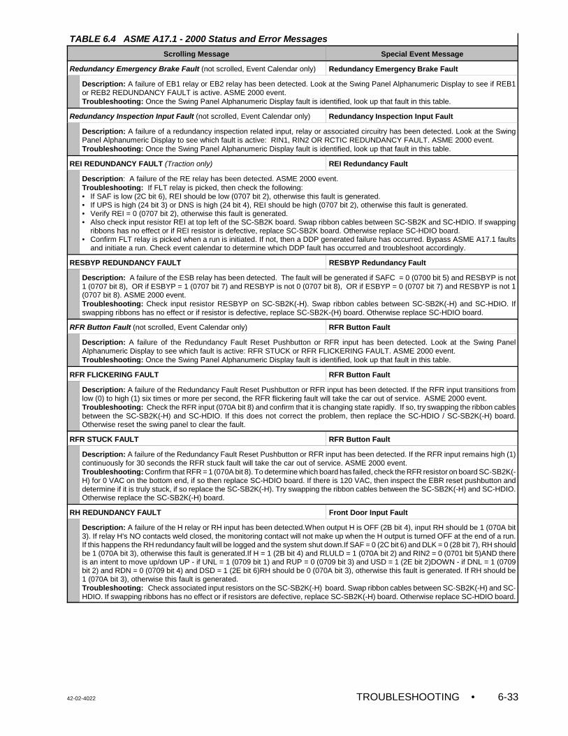
TABLE 6.4 ASME A17.1 - 2000 Status and Error Messages
Scrolling Message Special Event Message
42-02-4022 TROUBLESHOOTING • 6-33
Redundancy Emergency Brake Fault (not scrolled, Event Calendar only) Redundancy Emergency Brake Fault
Description: A failure of EB1 relay or EB2 relay has been detected. Look at the Swing Panel Alphanumeric Display to see if REB1or REB2 REDUNDANCY FAULT is active. ASME 2000 event.Troubleshooting: Once the Swing Panel Alphanumeric Display fault is identified, look up that fault in this table.
Redundancy Inspection Input Fault (not scrolled, Event Calendar only) Redundancy Inspection Input Fault
Description: A failure of a redundancy inspection related input, relay or associated circuitry has been detected. Look at the SwingPanel Alphanumeric Display to see which fault is active: RIN1, RIN2 OR RCTIC REDUNDANCY FAULT. ASME 2000 event.Troubleshooting: Once the Swing Panel Alphanumeric Display fault is identified, look up that fault in this table.
REI REDUNDANCY FAULT (Traction only) REI Redundancy Fault
Description: A failure of the RE relay has been detected. ASME 2000 event.Troubleshooting: If FLT relay is picked, then check the following:• If SAF is low (2C bit 6), REI should be low (0707 bit 2), otherwise this fault is generated.• If UPS is high (24 bit 3) or DNS is high (24 bit 4), REI should be high (0707 bit 2), otherwise this fault is generated.• Verify REI = 0 (0707 bit 2), otherwise this fault is generated.• Also check input resistor REI at top left of the SC-SB2K board. Swap ribbon cables between SC-SB2K and SC-HDIO. If swapping
ribbons has no effect or if REI resistor is defective, replace SC-SB2K board. Otherwise replace SC-HDIO board.• Confirm FLT relay is picked when a run is initiated. If not, then a DDP generated failure has occurred. Bypass ASME A17.1 faults
and initiate a run. Check event calendar to determine which DDP fault has occurred and troubleshoot accordingly.
RESBYP REDUNDANCY FAULT RESBYP Redundancy Fault
Description: A failure of the ESB relay has been detected. The fault will be generated if SAFC = 0 (0700 bit 5) and RESBYP is not1 (0707 bit 8), OR if ESBYP = 1 (0707 bit 7) and RESBYP is not 0 (0707 bit 8), OR if ESBYP = 0 (0707 bit 7) and RESBYP is not 1(0707 bit 8). ASME 2000 event.Troubleshooting: Check input resistor RESBYP on SC-SB2K(-H). Swap ribbon cables between SC-SB2K(-H) and SC-HDIO. Ifswapping ribbons has no effect or if resistor is defective, replace SC-SB2K-(H) board. Otherwise replace SC-HDIO board.
RFR Button Fault (not scrolled, Event Calendar only) RFR Button Fault
Description: A failure of the Redundancy Fault Reset Pushbutton or RFR input has been detected. Look at the Swing PanelAlphanumeric Display to see which fault is active: RFR STUCK or RFR FLICKERING FAULT. ASME 2000 event.Troubleshooting: Once the Swing Panel Alphanumeric Display fault is identified, look up that fault in this table.
RFR FLICKERING FAULT RFR Button Fault
Description: A failure of the Redundancy Fault Reset Pushbutton or RFR input has been detected. If the RFR input transitions fromlow (0) to high (1) six times or more per second, the RFR flickering fault will take the car out of service. ASME 2000 event. Troubleshooting: Check the RFR input (070A bit 8) and confirm that it is changing state rapidly. If so, try swapping the ribbon cablesbetween the SC-SB2K(-H) and SC-HDIO. If this does not correct the problem, then replace the SC-HDIO / SC-SB2K(-H) board.Otherwise reset the swing panel to clear the fault.
RFR STUCK FAULT RFR Button Fault
Description: A failure of the Redundancy Fault Reset Pushbutton or RFR input has been detected. If the RFR input remains high (1)continuously for 30 seconds the RFR stuck fault will take the car out of service. ASME 2000 event.Troubleshooting: Confirm that RFR = 1 (070A bit 8). To determine which board has failed, check the RFR resistor on board SC-SB2K(-H) for 0 VAC on the bottom end, if so then replace SC-HDIO board. If there is 120 VAC, then inspect the EBR reset pushbutton anddetermine if it is truly stuck, if so replace the SC-SB2K(-H). Try swapping the ribbon cables between the SC-SB2K(-H) and SC-HDIO.Otherwise replace the SC-SB2K(-H) board.
RH REDUNDANCY FAULT Front Door Input Fault
Description: A failure of the H relay or RH input has been detected.When output H is OFF (2B bit 4), input RH should be 1 (070A bit3). If relay H's NO contacts weld closed, the monitoring contact will not make up when the H output is turned OFF at the end of a run.If this happens the RH redundancy fault will be logged and the system shut down.If SAF = 0 (2C bit 6) and DLK = 0 (28 bit 7), RH shouldbe 1 (070A bit 3), otherwise this fault is generated.If H = 1 (2B bit 4) and RLULD = 1 (070A bit 2) and RIN2 = 0 (0701 bit 5)AND thereis an intent to move up/down UP - if UNL = 1 (0709 bit 1) and RUP = 0 (0709 bit 3) and USD = 1 (2E bit 2)DOWN - if DNL = 1 (0709bit 2) and RDN = 0 (0709 bit 4) and DSD = 1 (2E bit 6)RH should be 0 (070A bit 3), otherwise this fault is generated. If RH should be1 (070A bit 3), otherwise this fault is generated.Troubleshooting: Check associated input resistors on the SC-SB2K(-H) board. Swap ribbon cables between SC-SB2K(-H) and SC-HDIO. If swapping ribbons has no effect or if resistors are defective, replace SC-SB2K(-H) board. Otherwise replace SC-HDIO board.
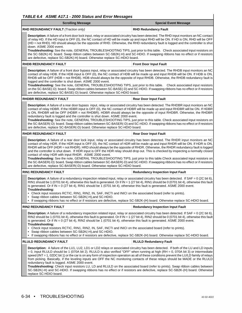
TABLE 6.4 ASME A17.1 - 2000 Status and Error Messages
Scrolling Message Special Event Message
• TROUBLESHOOTING 42-02-40226-34
RHD REDUNDANCY FAULT (Traction only) RHD Redundancy Fault
Description: A failure of a front door lock input, relay or associated circuitry has been detected. The RHD input monitors an NC contactof relay HD. If the HD input is OFF (0), the NC contact of HD will be made up and input RHD will be ON. If HD is ON, RHD will be OFF(HD = not RHD). HD should always be the opposite of RHD. Otherwise, the RHD redundancy fault is logged and the controller is shutdown. ASME 2000 event.Troubleshooting: See the note, GENERAL TROUBLESHOOTING TIPS, just prior to this table. Check associated input resistors onthe SC-SB2K(-H) board. Swap ribbon cables between SC-SB2K(-H) and SC-HDIO. If swapping ribbons has no effect or if resistorsare defective, replace SC-SB2K(-H) board. Otherwise replace SC-HDIO board.
RHDB REDUNDANCY FAULT Front Door Input Fault
Description: A failure of a front door bypass input, relay or associated circuitry has been detected. The RHDB input monitors an NCcontact of relay HDB. If the HDB input is OFF (0), the NC contact of HDB will be made up and input RHDB will be ON. If HDB is ON,RHDB will be OFF (HDB = not RHDB). HDB should always be the opposite of input RHDB. Otherwise, the RHDB redundancy fault islogged and the controller is shut down. ASME 2000 event.Troubleshooting: See the note, GENERAL TROUBLESHOOTING TIPS, just prior to this table. Check associated input resistorson the SC-BASE(-D) board. Swap ribbon cables between SC-BASE(-D) and SC-HDIO. If swapping ribbons has no effect or if resistorsare defective, replace SC-BASE(-D) board. Otherwise replace SC-HDIO board.
RHDBR REDUNDANCY FAULT Rear Door Input Fault
Description: A failure of a rear door bypass input, relay or associated circuitry has been detected. The RHDBR input monitors an NCcontact of relay HDBR. If the HDBR input is OFF (0), the NC contact of HDBR will be made up and input RHDBR will be ON. If HDBRis ON, RHDBR will be OFF (HDBR = not RHDBR). HDBR should always be the opposite of input RHDBR. Otherwise, the RHDBRredundancy fault is logged and the controller is shut down. ASME 2000 event.Troubleshooting: See the note, GENERAL TROUBLESHOOTING TIPS, just prior to this table. Check associated input resistors onthe SC-BASER(-D) board. Swap ribbon cables between SC-BASER(-D) and SC-HDIO. If swapping ribbons has no effect or if resistorsare defective, replace SC-BASER(-D) board. Otherwise replace SC-HDIO board.
RHDR REDUNDANCY FAULT Rear Door Input Fault
Description: A failure of a rear door lock input, relay or associated circuitry has been detected. The RHDR input monitors an NCcontact of relay HDR. If the HDR input is OFF (0), the NC contact of HDR will be made up and input RHDR will be ON. If HDR is ON,RHDR will be OFF (HDR = not RHDR). HRD should always be the opposite of RHDR. Otherwise, the RHDR redundancy fault is loggedand the controller is shut down. If HDR input is OFF the HDR relay should drop out. This is checked by inspecting a normally closedcontact of relay HDR with input RHDR. ASME 2000 event.Troubleshooting: See the note, GENERAL TROUBLESHOOTING TIPS, just prior to this table.Check associated input resistors onthe SC-BASER(-D) board. Swap ribbon cables between SC-BASER(-D) and SC-HDIO. If swapping ribbons has no effect or if resistorsare defective, replace SC-BASER(-D) board. Otherwise replace SC-HDIO board.
RIN1 REDUNDANCY FAULT Redundancy Inspection Input Fault
Description: A failure of a redundancy inspection related input, relay or associated circuitry has been detected. If SAF = 0 (2C bit 6),RIN1 should be 1 (0701 bit 4), otherwise this fault is generated. Or if IN = 1 (27 bit 4), RIN1 should be 0 (0701 bit 4), otherwise this faultis generated. Or if IN = 0 (27 bit 4), RIN1 should be 1 (0701 bit 4), otherwise this fault is generated. ASME 2000 event.Troubleshooting:• Check input resistors RCTIC, RIN1, RIN2, IN, SAF, INCTI and INICI on the associated board (refer to prints). • Swap ribbon cables between SC-SB2K(-H),and SC-HDIO.• If swapping ribbons has no effect or if resistors are defective, replace SC-SB2K-(H) board. Otherwise replace SC-HDIO board.
RIN2 REDUNDANCY FAULT Redundancy Inspection Input Fault
Description: A failure of a redundancy inspection related input, relay or associated circuitry has been detected. If SAF = 0 (2C bit 6),RIN2 should be 1 (0701 bit 4), otherwise this fault is generated. Or if IN = 1 (27 bit 4), RIN2 should be 0 (0701 bit 4), otherwise this faultis generated. Or if IN = 0 (27 bit 4), RIN2 should be 1 (0701 bit 4), otherwise this fault is generated. ASME 2000 event.Troubleshooting:• Check input resistors RCTIC, RIN1, RIN2, IN, SAF, INCTI and INICI on the associated board (refer to prints). • Swap ribbon cables between SC-SB2K(-H),and SC-HDIO.• If swapping ribbons has no effect or if resistors are defective, replace SC-SB2K-(H) board. Otherwise replace SC-HDIO board.
RLULD REDUNDANCY FAULT RLULD Redundancy Fault
Description: A failure of the LU1, LU2, LD1 or LD2 relays or associated circuitry has been detected. If both of the LU and LD inputs= 0, input RLULD should be 1 (070A bit 2). RLULD is also verified "OFF" when running at high (RH = 0, 070A bit 3) or intermediatespeed (INT = 1, 02DC bit 1) or the car is on any form of inspection operation as all of these conditions prevent the LU/LD family of relaysfrom picking. Basically, if the leveling inputs are OFF the NC monitoring contacts of these relays should be MADE or the RLULDredundancy fault is logged. ASME 2000 event.Troubleshooting: Check input resistors LU, LD and RLULD on the associated board (refer to prints). Swap ribbon cables betweenSC-SB2K(-H) and SC-HDIO. If swapping ribbons has no effect or if resistors are defective, replace SC-SB2K-(H) board. Otherwisereplace SC-HDIO board.
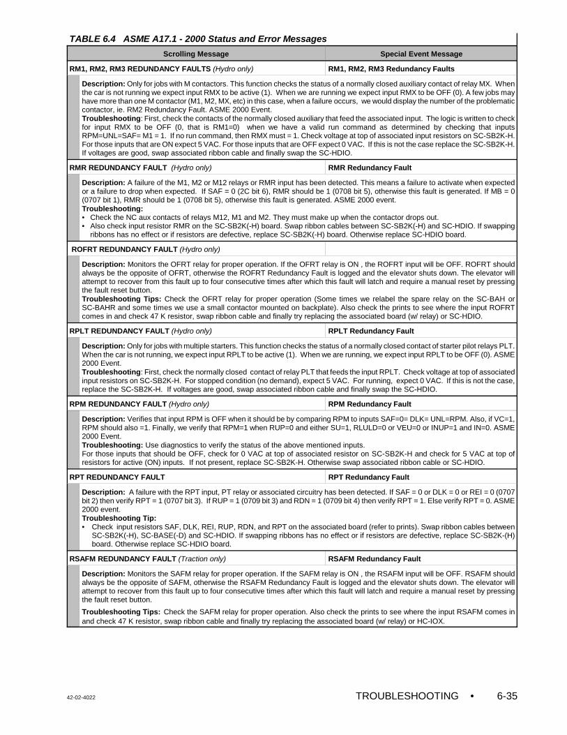
TABLE 6.4 ASME A17.1 - 2000 Status and Error Messages
Scrolling Message Special Event Message
42-02-4022 TROUBLESHOOTING • 6-35
RM1, RM2, RM3 REDUNDANCY FAULTS (Hydro only) RM1, RM2, RM3 Redundancy Faults
Description: Only for jobs with M contactors. This function checks the status of a normally closed auxiliary contact of relay MX. Whenthe car is not running we expect input RMX to be active (1). When we are running we expect input RMX to be OFF (0). A few jobs mayhave more than one M contactor (M1, M2, MX, etc) in this case, when a failure occurs, we would display the number of the problematiccontactor, ie. RM2 Redundancy Fault. ASME 2000 Event.Troubleshooting: First, check the contacts of the normally closed auxiliary that feed the associated input. The logic is written to checkfor input RMX to be OFF (0, that is RM1=0) when we have a valid run command as determined by checking that inputsRPM=UNL=SAF= M1 = 1. If no run command, then RMX must = 1. Check voltage at top of associated input resistors on SC-SB2K-H.For those inputs that are ON expect 5 VAC. For those inputs that are OFF expect 0 VAC. If this is not the case replace the SC-SB2K-H.If voltages are good, swap associated ribbon cable and finally swap the SC-HDIO.
RMR REDUNDANCY FAULT (Hydro only) RMR Redundancy Fault
Description: A failure of the M1, M2 or M12 relays or RMR input has been detected. This means a failure to activate when expectedor a failure to drop when expected. If SAF = 0 (2C bit 6), RMR should be 1 (0708 bit 5), otherwise this fault is generated. If MB = 0(0707 bit 1), RMR should be 1 (0708 bit 5), otherwise this fault is generated. ASME 2000 event.Troubleshooting:• Check the NC aux contacts of relays M12, M1 and M2. They must make up when the contactor drops out.• Also check input resistor RMR on the SC-SB2K(-H) board. Swap ribbon cables between SC-SB2K(-H) and SC-HDIO. If swapping
ribbons has no effect or if resistors are defective, replace SC-SB2K(-H) board. Otherwise replace SC-HDIO board.
ROFRT REDUNDANCY FAULT (Hydro only)
Description: Monitors the OFRT relay for proper operation. If the OFRT relay is ON , the ROFRT input will be OFF. ROFRT shouldalways be the opposite of OFRT, otherwise the ROFRT Redundancy Fault is logged and the elevator shuts down. The elevator willattempt to recover from this fault up to four consecutive times after which this fault will latch and require a manual reset by pressingthe fault reset button.Troubleshooting Tips: Check the OFRT relay for proper operation (Some times we relabel the spare relay on the SC-BAH orSC-BAHR and some times we use a small contactor mounted on backplate). Also check the prints to see where the input ROFRTcomes in and check 47 K resistor, swap ribbon cable and finally try replacing the associated board (w/ relay) or SC-HDIO.
RPLT REDUNDANCY FAULT (Hydro only) RPLT Redundancy Fault
Description: Only for jobs with multiple starters. This function checks the status of a normally closed contact of starter pilot relays PLT.When the car is not running, we expect input RPLT to be active (1). When we are running, we expect input RPLT to be OFF (0). ASME2000 Event.Troubleshooting: First, check the normally closed contact of relay PLT that feeds the input RPLT. Check voltage at top of associatedinput resistors on SC-SB2K-H. For stopped condition (no demand), expect 5 VAC. For running, expect 0 VAC. If this is not the case,replace the SC-SB2K-H. If voltages are good, swap associated ribbon cable and finally swap the SC-HDIO.
RPM REDUNDANCY FAULT (Hydro only) RPM Redundancy Fault
Description: Verifies that input RPM is OFF when it should be by comparing RPM to inputs SAF=0= DLK= UNL=RPM. Also, if VC=1,RPM should also =1. Finally, we verify that RPM=1 when RUP=0 and either SU=1, RLULD=0 or VEU=0 or INUP=1 and IN=0. ASME2000 Event. Troubleshooting: Use diagnostics to verify the status of the above mentioned inputs. For those inputs that should be OFF, check for 0 VAC at top of associated resistor on SC-SB2K-H and check for 5 VAC at top ofresistors for active (ON) inputs. If not present, replace SC-SB2K-H. Otherwise swap associated ribbon cable or SC-HDIO.
RPT REDUNDANCY FAULT RPT Redundancy Fault
Description: A failure with the RPT input, PT relay or associated circuitry has been detected. If SAF = 0 or DLK = 0 or REI = 0 (0707bit 2) then verify RPT = 1 (0707 bit 3). If RUP = 1 (0709 bit 3) and RDN = 1 (0709 bit 4) then verify RPT = 1. Else verify RPT = 0. ASME2000 event.Troubleshooting Tip:• Check input resistors SAF, DLK, REI, RUP, RDN, and RPT on the associated board (refer to prints). Swap ribbon cables between
SC-SB2K(-H), SC-BASE(-D) and SC-HDIO. If swapping ribbons has no effect or if resistors are defective, replace SC-SB2K-(H)board. Otherwise replace SC-HDIO board.
RSAFM REDUNDANCY FAULT (Traction only) RSAFM Redundancy Fault
Description: Monitors the SAFM relay for proper operation. If the SAFM relay is ON , the RSAFM input will be OFF. RSAFM shouldalways be the opposite of SAFM, otherwise the RSAFM Redundancy Fault is logged and the elevator shuts down. The elevator willattempt to recover from this fault up to four consecutive times after which this fault will latch and require a manual reset by pressingthe fault reset button.
Troubleshooting Tips: Check the SAFM relay for proper operation. Also check the prints to see where the input RSAFM comes inand check 47 K resistor, swap ribbon cable and finally try replacing the associated board (w/ relay) or HC-IOX.
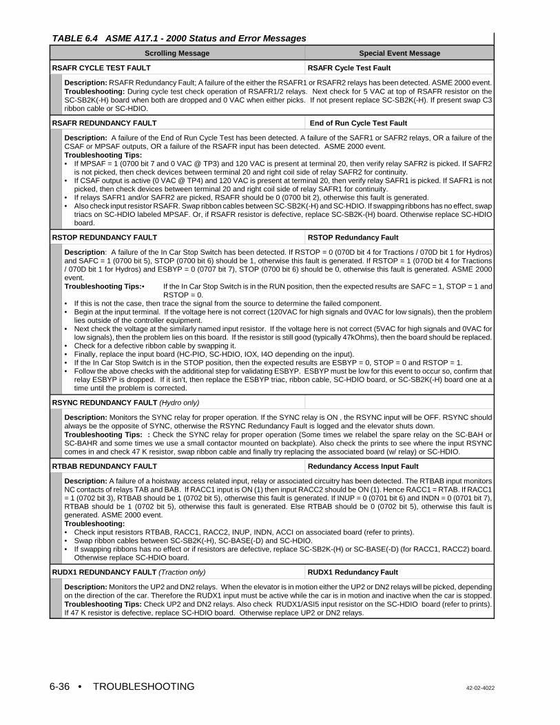
TABLE 6.4 ASME A17.1 - 2000 Status and Error Messages
Scrolling Message Special Event Message
• TROUBLESHOOTING 42-02-40226-36
RSAFR CYCLE TEST FAULT RSAFR Cycle Test Fault
Description: RSAFR Redundancy Fault; A failure of the either the RSAFR1 or RSAFR2 relays has been detected. ASME 2000 event.Troubleshooting: During cycle test check operation of RSAFR1/2 relays. Next check for 5 VAC at top of RSAFR resistor on theSC-SB2K(-H) board when both are dropped and 0 VAC when either picks. If not present replace SC-SB2K(-H). If present swap C3ribbon cable or SC-HDIO.
RSAFR REDUNDANCY FAULT End of Run Cycle Test Fault
Description: A failure of the End of Run Cycle Test has been detected. A failure of the SAFR1 or SAFR2 relays, OR a failure of theCSAF or MPSAF outputs, OR a failure of the RSAFR input has been detected. ASME 2000 event.Troubleshooting Tips:• If MPSAF = 1 (0700 bit 7 and 0 VAC @ TP3) and 120 VAC is present at terminal 20, then verify relay SAFR2 is picked. If SAFR2
is not picked, then check devices between terminal 20 and right coil side of relay SAFR2 for continuity.• If CSAF output is active (0 VAC @ TP4) and 120 VAC is present at terminal 20, then verify relay SAFR1 is picked. If SAFR1 is not
picked, then check devices between terminal 20 and right coil side of relay SAFR1 for continuity.• If relays SAFR1 and/or SAFR2 are picked, RSAFR should be 0 (0700 bit 2), otherwise this fault is generated. • Also check input resistor RSAFR. Swap ribbon cables between SC-SB2K(-H) and SC-HDIO. If swapping ribbons has no effect, swap
triacs on SC-HDIO labeled MPSAF. Or, if RSAFR resistor is defective, replace SC-SB2K-(H) board. Otherwise replace SC-HDIOboard.
RSTOP REDUNDANCY FAULT RSTOP Redundancy Fault
Description: A failure of the In Car Stop Switch has been detected. If RSTOP = 0 (070D bit 4 for Tractions / 070D bit 1 for Hydros)and SAFC = 1 (0700 bit 5), STOP (0700 bit 6) should be 1, otherwise this fault is generated. If RSTOP = 1 (070D bit 4 for Tractions/ 070D bit 1 for Hydros) and ESBYP = 0 (0707 bit 7), STOP (0700 bit 6) should be 0, otherwise this fault is generated. ASME 2000event.Troubleshooting Tips:• If the In Car Stop Switch is in the RUN position, then the expected results are SAFC = 1, STOP = 1 and
RSTOP = 0. • If this is not the case, then trace the signal from the source to determine the failed component. • Begin at the input terminal. If the voltage here is not correct (120VAC for high signals and 0VAC for low signals), then the problem
lies outside of the controller equipment.• Next check the voltage at the similarly named input resistor. If the voltage here is not correct (5VAC for high signals and 0VAC for
low signals), then the problem lies on this board. If the resistor is still good (typically 47kOhms), then the board should be replaced.• Check for a defective ribbon cable by swapping it.• Finally, replace the input board (HC-PIO, SC-HDIO, IOX, I4O depending on the input).• If the In Car Stop Switch is in the STOP position, then the expected results are ESBYP = 0, STOP = 0 and RSTOP = 1.• Follow the above checks with the additional step for validating ESBYP. ESBYP must be low for this event to occur so, confirm that
relay ESBYP is dropped. If it isn’t, then replace the ESBYP triac, ribbon cable, SC-HDIO board, or SC-SB2K(-H) board one at atime until the problem is corrected.
RSYNC REDUNDANCY FAULT (Hydro only)
Description: Monitors the SYNC relay for proper operation. If the SYNC relay is ON , the RSYNC input will be OFF. RSYNC shouldalways be the opposite of SYNC, otherwise the RSYNC Redundancy Fault is logged and the elevator shuts down.Troubleshooting Tips: : Check the SYNC relay for proper operation (Some times we relabel the spare relay on the SC-BAH orSC-BAHR and some times we use a small contactor mounted on backplate). Also check the prints to see where the input RSYNCcomes in and check 47 K resistor, swap ribbon cable and finally try replacing the associated board (w/ relay) or SC-HDIO.
RTBAB REDUNDANCY FAULT Redundancy Access Input Fault
Description: A failure of a hoistway access related input, relay or associated circuitry has been detected. The RTBAB input monitorsNC contacts of relays TAB and BAB. If RACC1 input is ON (1) then input RACC2 should be ON (1). Hence RACC1 = RTAB. If RACC1= 1 (0702 bit 3), RTBAB should be 1 (0702 bit 5), otherwise this fault is generated. If INUP = 0 (0701 bit 6) and INDN = 0 (0701 bit 7),RTBAB should be 1 (0702 bit 5), otherwise this fault is generated. Else RTBAB should be 0 (0702 bit 5), otherwise this fault isgenerated. ASME 2000 event.Troubleshooting: • Check input resistors RTBAB, RACC1, RACC2, INUP, INDN, ACCI on associated board (refer to prints). • Swap ribbon cables between SC-SB2K(-H), SC-BASE(-D) and SC-HDIO. • If swapping ribbons has no effect or if resistors are defective, replace SC-SB2K-(H) or SC-BASE(-D) (for RACC1, RACC2) board.
Otherwise replace SC-HDIO board.
RUDX1 REDUNDANCY FAULT (Traction only) RUDX1 Redundancy Fault
Description: Monitors the UP2 and DN2 relays. When the elevator is in motion either the UP2 or DN2 relays will be picked, dependingon the direction of the car. Therefore the RUDX1 input must be active while the car is in motion and inactive when the car is stopped.Troubleshooting Tips: Check UP2 and DN2 relays. Also check RUDX1/ASI5 input resistor on the SC-HDIO board (refer to prints).If 47 K resistor is defective, replace SC-HDIO board. Otherwise replace UP2 or DN2 relays.
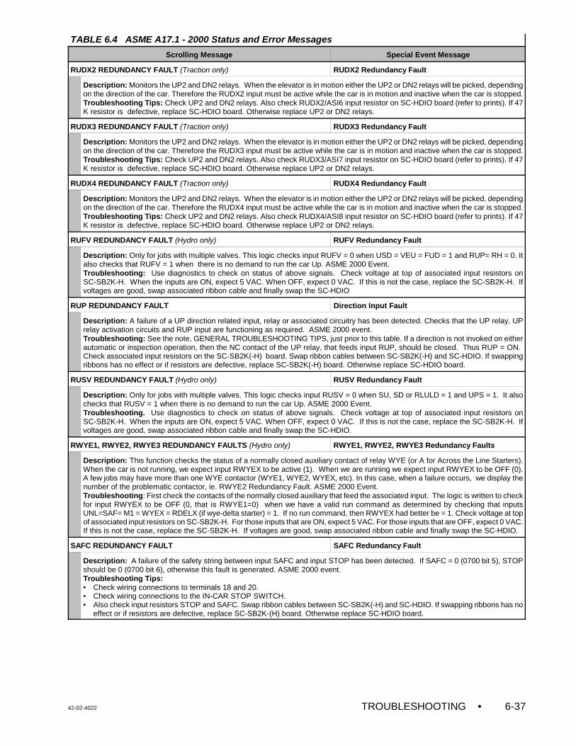
TABLE 6.4 ASME A17.1 - 2000 Status and Error Messages
Scrolling Message Special Event Message
42-02-4022 TROUBLESHOOTING • 6-37
RUDX2 REDUNDANCY FAULT (Traction only) RUDX2 Redundancy Fault
Description: Monitors the UP2 and DN2 relays. When the elevator is in motion either the UP2 or DN2 relays will be picked, dependingon the direction of the car. Therefore the RUDX2 input must be active while the car is in motion and inactive when the car is stopped.Troubleshooting Tips: Check UP2 and DN2 relays. Also check RUDX2/ASI6 input resistor on SC-HDIO board (refer to prints). If 47K resistor is defective, replace SC-HDIO board. Otherwise replace UP2 or DN2 relays.
RUDX3 REDUNDANCY FAULT (Traction only) RUDX3 Redundancy Fault
Description: Monitors the UP2 and DN2 relays. When the elevator is in motion either the UP2 or DN2 relays will be picked, dependingon the direction of the car. Therefore the RUDX3 input must be active while the car is in motion and inactive when the car is stopped.Troubleshooting Tips: Check UP2 and DN2 relays. Also check RUDX3/ASI7 input resistor on SC-HDIO board (refer to prints). If 47K resistor is defective, replace SC-HDIO board. Otherwise replace UP2 or DN2 relays.
RUDX4 REDUNDANCY FAULT (Traction only) RUDX4 Redundancy Fault
Description: Monitors the UP2 and DN2 relays. When the elevator is in motion either the UP2 or DN2 relays will be picked, dependingon the direction of the car. Therefore the RUDX4 input must be active while the car is in motion and inactive when the car is stopped.Troubleshooting Tips: Check UP2 and DN2 relays. Also check RUDX4/ASI8 input resistor on SC-HDIO board (refer to prints). If 47K resistor is defective, replace SC-HDIO board. Otherwise replace UP2 or DN2 relays.
RUFV REDUNDANCY FAULT (Hydro only) RUFV Redundancy Fault
Description: Only for jobs with multiple valves. This logic checks input RUFV = 0 when USD = VEU = FUD = 1 and RUP= RH = 0. Italso checks that RUFV = 1 when there is no demand to run the car Up. ASME 2000 Event.Troubleshooting: Use diagnostics to check on status of above signals. Check voltage at top of associated input resistors onSC-SB2K-H. When the inputs are ON, expect 5 VAC. When OFF, expect 0 VAC. If this is not the case, replace the SC-SB2K-H. Ifvoltages are good, swap associated ribbon cable and finally swap the SC-HDIO
RUP REDUNDANCY FAULT Direction Input Fault
Description: A failure of a UP direction related input, relay or associated circuitry has been detected. Checks that the UP relay, UPrelay activation circuits and RUP input are functioning as required. ASME 2000 event.Troubleshooting: See the note, GENERAL TROUBLESHOOTING TIPS, just prior to this table. If a direction is not invoked on eitherautomatic or inspection operation, then the NC contact of the UP relay, that feeds input RUP, should be closed. Thus RUP = ON. Check associated input resistors on the SC-SB2K(-H) board. Swap ribbon cables between SC-SB2K(-H) and SC-HDIO. If swappingribbons has no effect or if resistors are defective, replace SC-SB2K(-H) board. Otherwise replace SC-HDIO board.
RUSV REDUNDANCY FAULT (Hydro only) RUSV Redundancy Fault
Description: Only for jobs with multiple valves. This logic checks input RUSV = 0 when SU, SD or RLULD = 1 and UPS = 1. It alsochecks that RUSV = 1 when there is no demand to run the car Up. ASME 2000 Event. Troubleshooting. Use diagnostics to check on status of above signals. Check voltage at top of associated input resistors onSC-SB2K-H. When the inputs are ON, expect 5 VAC. When OFF, expect 0 VAC. If this is not the case, replace the SC-SB2K-H. Ifvoltages are good, swap associated ribbon cable and finally swap the SC-HDIO.
RWYE1, RWYE2, RWYE3 REDUNDANCY FAULTS (Hydro only) RWYE1, RWYE2, RWYE3 Redundancy Faults
Description: This function checks the status of a normally closed auxiliary contact of relay WYE (or A for Across the Line Starters).When the car is not running, we expect input RWYEX to be active (1). When we are running we expect input RWYEX to be OFF (0).A few jobs may have more than one WYE contactor (WYE1, WYE2, WYEX, etc). In this case, when a failure occurs, we display thenumber of the problematic contactor, ie. RWYE2 Redundancy Fault. ASME 2000 Event.Troubleshooting: First check the contacts of the normally closed auxiliary that feed the associated input. The logic is written to checkfor input RWYEX to be OFF (0, that is RWYE1=0) when we have a valid run command as determined by checking that inputsUNL=SAF= M1 = WYEX = RDELX (if wye-delta starter) = 1. If no run command, then RWYEX had better be = 1. Check voltage at topof associated input resistors on SC-SB2K-H. For those inputs that are ON, expect 5 VAC. For those inputs that are OFF, expect 0 VAC.If this is not the case, replace the SC-SB2K-H. If voltages are good, swap associated ribbon cable and finally swap the SC-HDIO.
SAFC REDUNDANCY FAULT SAFC Redundancy Fault
Description: A failure of the safety string between input SAFC and input STOP has been detected. If SAFC = 0 (0700 bit 5), STOPshould be 0 (0700 bit 6), otherwise this fault is generated. ASME 2000 event.Troubleshooting Tips:• Check wiring connections to terminals 18 and 20.• Check wiring connections to the IN-CAR STOP SWITCH. • Also check input resistors STOP and SAFC. Swap ribbon cables between SC-SB2K(-H) and SC-HDIO. If swapping ribbons has no
effect or if resistors are defective, replace SC-SB2K-(H) board. Otherwise replace SC-HDIO board.
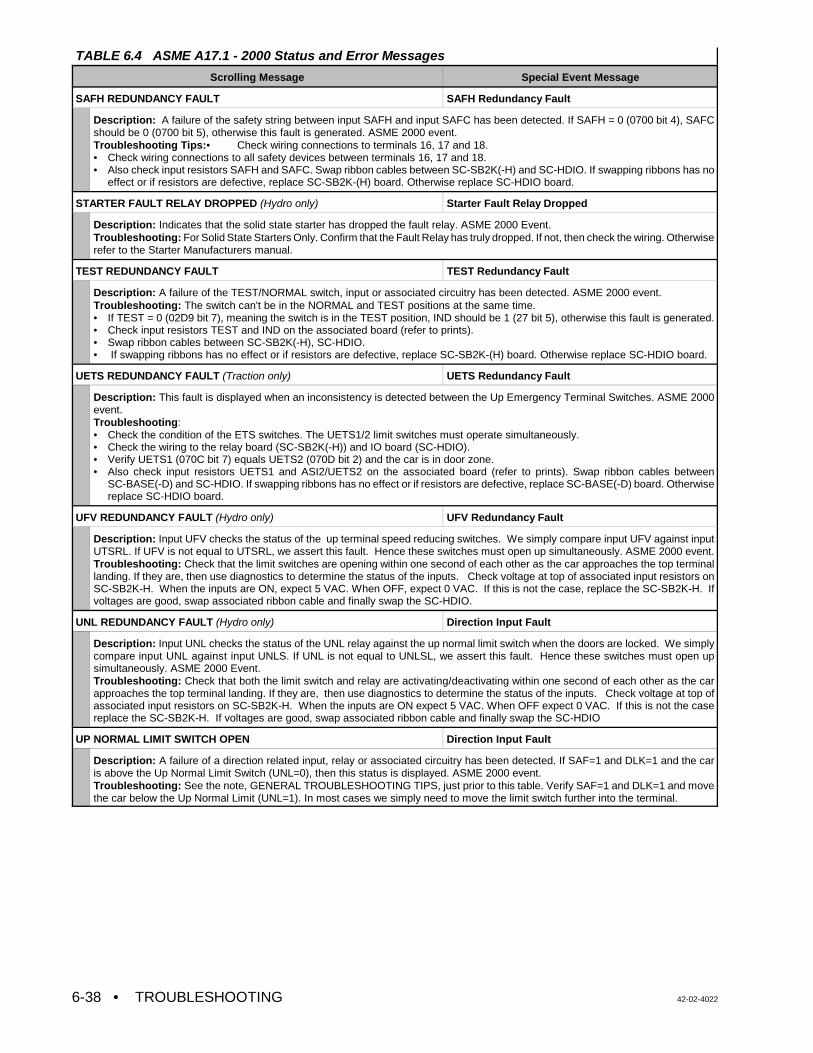
TABLE 6.4 ASME A17.1 - 2000 Status and Error Messages
Scrolling Message Special Event Message
• TROUBLESHOOTING 42-02-40226-38
SAFH REDUNDANCY FAULT SAFH Redundancy Fault
Description: A failure of the safety string between input SAFH and input SAFC has been detected. If SAFH = 0 (0700 bit 4), SAFCshould be 0 (0700 bit 5), otherwise this fault is generated. ASME 2000 event.Troubleshooting Tips:• Check wiring connections to terminals 16, 17 and 18.• Check wiring connections to all safety devices between terminals 16, 17 and 18.• Also check input resistors SAFH and SAFC. Swap ribbon cables between SC-SB2K(-H) and SC-HDIO. If swapping ribbons has no
effect or if resistors are defective, replace SC-SB2K-(H) board. Otherwise replace SC-HDIO board.
STARTER FAULT RELAY DROPPED (Hydro only) Starter Fault Relay Dropped
Description: Indicates that the solid state starter has dropped the fault relay. ASME 2000 Event.Troubleshooting: For Solid State Starters Only. Confirm that the Fault Relay has truly dropped. If not, then check the wiring. Otherwiserefer to the Starter Manufacturers manual.
TEST REDUNDANCY FAULT TEST Redundancy Fault
Description: A failure of the TEST/NORMAL switch, input or associated circuitry has been detected. ASME 2000 event.Troubleshooting: The switch can't be in the NORMAL and TEST positions at the same time.• If TEST = 0 (02D9 bit 7), meaning the switch is in the TEST position, IND should be 1 (27 bit 5), otherwise this fault is generated.• Check input resistors TEST and IND on the associated board (refer to prints). • Swap ribbon cables between SC-SB2K(-H), SC-HDIO.• If swapping ribbons has no effect or if resistors are defective, replace SC-SB2K-(H) board. Otherwise replace SC-HDIO board.
UETS REDUNDANCY FAULT (Traction only) UETS Redundancy Fault
Description: This fault is displayed when an inconsistency is detected between the Up Emergency Terminal Switches. ASME 2000event.Troubleshooting: • Check the condition of the ETS switches. The UETS1/2 limit switches must operate simultaneously.• Check the wiring to the relay board (SC-SB2K(-H)) and IO board (SC-HDIO).• Verify UETS1 (070C bit 7) equals UETS2 (070D bit 2) and the car is in door zone.• Also check input resistors UETS1 and ASI2/UETS2 on the associated board (refer to prints). Swap ribbon cables between
SC-BASE(-D) and SC-HDIO. If swapping ribbons has no effect or if resistors are defective, replace SC-BASE(-D) board. Otherwisereplace SC-HDIO board.
UFV REDUNDANCY FAULT (Hydro only) UFV Redundancy Fault
Description: Input UFV checks the status of the up terminal speed reducing switches. We simply compare input UFV against inputUTSRL. If UFV is not equal to UTSRL, we assert this fault. Hence these switches must open up simultaneously. ASME 2000 event.Troubleshooting: Check that the limit switches are opening within one second of each other as the car approaches the top terminallanding. If they are, then use diagnostics to determine the status of the inputs. Check voltage at top of associated input resistors onSC-SB2K-H. When the inputs are ON, expect 5 VAC. When OFF, expect 0 VAC. If this is not the case, replace the SC-SB2K-H. Ifvoltages are good, swap associated ribbon cable and finally swap the SC-HDIO.
UNL REDUNDANCY FAULT (Hydro only) Direction Input Fault
Description: Input UNL checks the status of the UNL relay against the up normal limit switch when the doors are locked. We simplycompare input UNL against input UNLS. If UNL is not equal to UNLSL, we assert this fault. Hence these switches must open upsimultaneously. ASME 2000 Event.Troubleshooting: Check that both the limit switch and relay are activating/deactivating within one second of each other as the carapproaches the top terminal landing. If they are, then use diagnostics to determine the status of the inputs. Check voltage at top ofassociated input resistors on SC-SB2K-H. When the inputs are ON expect 5 VAC. When OFF expect 0 VAC. If this is not the casereplace the SC-SB2K-H. If voltages are good, swap associated ribbon cable and finally swap the SC-HDIO
UP NORMAL LIMIT SWITCH OPEN Direction Input Fault
Description: A failure of a direction related input, relay or associated circuitry has been detected. If SAF=1 and DLK=1 and the caris above the Up Normal Limit Switch (UNL=0), then this status is displayed. ASME 2000 event.Troubleshooting: See the note, GENERAL TROUBLESHOOTING TIPS, just prior to this table. Verify SAF=1 and DLK=1 and movethe car below the Up Normal Limit (UNL=1). In most cases we simply need to move the limit switch further into the terminal.
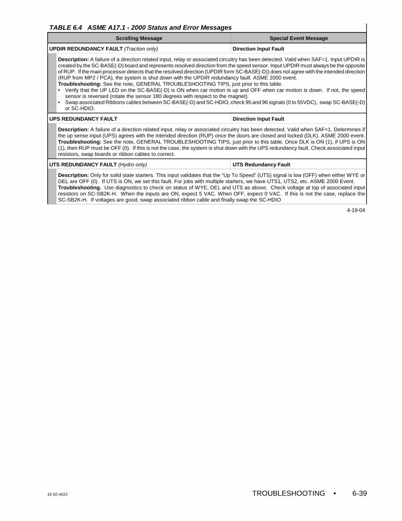
TABLE 6.4 ASME A17.1 - 2000 Status and Error Messages
Scrolling Message Special Event Message
42-02-4022 TROUBLESHOOTING • 6-39
UPDIR REDUNDANCY FAULT (Traction only) Direction Input Fault
Description: A failure of a direction related input, relay or associated circuitry has been detected. Valid when SAF=1. Input UPDIR iscreated by the SC-BASE(-D) board and represents resolved direction from the speed sensor. Input UPDIR must always be the oppositeof RUP. If the main processor detects that the resolved direction (UPDIR form SC-BASE(-D)) does not agree with the intended direction(RUP from MP2 / PCA), the system is shut down with the UPDIR redundancy fault. ASME 2000 event. Troubleshooting: See the note, GENERAL TROUBLESHOOTING TIPS, just prior to this table. • Verify that the UP LED on the SC-BASE(-D) is ON when car motion is up and OFF when car motion is down. If not, the speed
sensor is reversed (rotate the sensor 180 degrees with respect to the magnet). • Swap associated Ribbons cables between SC-BASE(-D) and SC-HDIO, check 95 and 96 signals (0 to 55VDC), swap SC-BASE(-D)
or SC-HDIO.
UPS REDUNDANCY FAULT Direction Input Fault
Description: A failure of a direction related input, relay or associated circuitry has been detected. Valid when SAF=1. Determines ifthe up sense input (UPS) agrees with the intended direction (RUP) once the doors are closed and locked (DLK). ASME 2000 event.Troubleshooting: See the note, GENERAL TROUBLESHOOTING TIPS, just prior to this table. Once DLK is ON (1), if UPS is ON(1), then RUP must be OFF (0). If this is not the case, the system is shut down with the UPS redundancy fault. Check associated inputresistors, swap boards or ribbon cables to correct.
UTS REDUNDANCY FAULT (Hydro only) UTS Redundancy Fault
Description: Only for solid state starters. This input validates that the “Up To Speed” (UTS) signal is low (OFF) when either WYE orDEL are OFF (0). If UTS is ON, we set this fault. For jobs with multiple starters, we have UTS1, UTS2, etc. ASME 2000 Event. Troubleshooting. Use diagnostics to check on status of WYE, DEL and UTS as above. Check voltage at top of associated inputresistors on SC-SB2K-H. When the inputs are ON, expect 5 VAC. When OFF, expect 0 VAC. If this is not the case, replace theSC-SB2K-H. If voltages are good, swap associated ribbon cable and finally swap the SC-HDIO
4-19-04
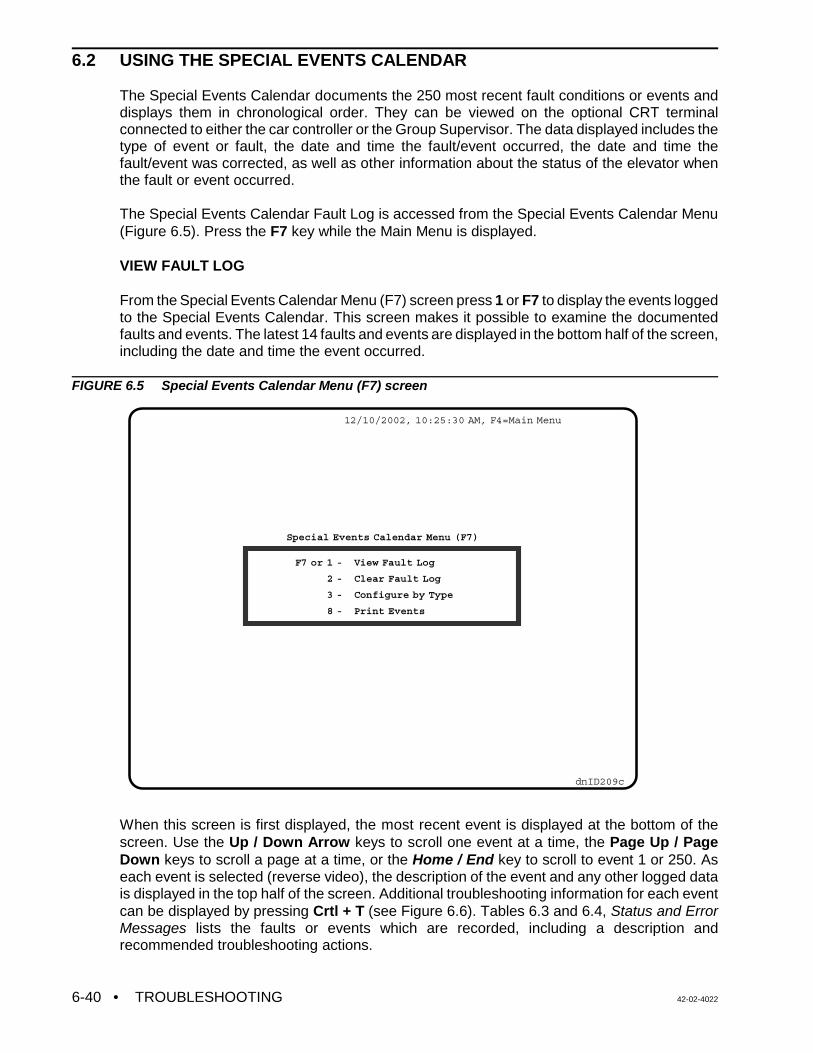
• TROUBLESHOOTING 42-02-40226-40
12/10/2002, 10:25:30 AM, F4=Main Menu
dnID209c
Special Events Calendar Menu (F7)
F7 or 1 -
2 -
3 -
8 -
View Fault Log
Clear Fault Log
Configure by Type
Print Events
6.2 USING THE SPECIAL EVENTS CALENDAR
The Special Events Calendar documents the 250 most recent fault conditions or events anddisplays them in chronological order. They can be viewed on the optional CRT terminalconnected to either the car controller or the Group Supervisor. The data displayed includes thetype of event or fault, the date and time the fault/event occurred, the date and time thefault/event was corrected, as well as other information about the status of the elevator whenthe fault or event occurred.
The Special Events Calendar Fault Log is accessed from the Special Events Calendar Menu(Figure 6.5). Press the F7 key while the Main Menu is displayed.
VIEW FAULT LOG
From the Special Events Calendar Menu (F7) screen press 1 or F7 to display the events loggedto the Special Events Calendar. This screen makes it possible to examine the documentedfaults and events. The latest 14 faults and events are displayed in the bottom half of the screen,including the date and time the event occurred.
FIGURE 6.5 Special Events Calendar Menu (F7) screen
When this screen is first displayed, the most recent event is displayed at the bottom of thescreen. Use the Up / Down Arrow keys to scroll one event at a time, the Page Up / PageDown keys to scroll a page at a time, or the Home / End key to scroll to event 1 or 250. Aseach event is selected (reverse video), the description of the event and any other logged datais displayed in the top half of the screen. Additional troubleshooting information for each eventcan be displayed by pressing Crtl + T (see Figure 6.6). Tables 6.3 and 6.4, Status and ErrorMessages lists the faults or events which are recorded, including a description andrecommended troubleshooting actions.
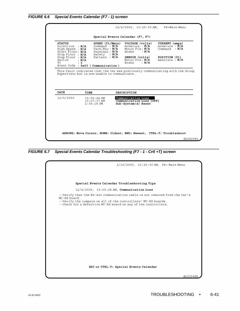
42-02-4022 TROUBLESHOOTING • 6-41
2/16/2000, 10:25:30 AM, F4= Main Menu
dnID248b
Special Events Calendar Troubleshooting Tips
12/4/2000, 10:05:28 AM, Communication Loss
--Verify that the RS-422 communication cable is not removed from the Car'sMC-RS board.--Verify the jumpers on all of the controllers' MC-RS boards.--Check for a defective MC-RS board on any of the controllers.
ESC or CTRL-T: Special Events Calendar
DESCRIPTION
Communication LossCommunication Loss [OFF]Sub-System(s) Reset
: N/A: N/A: N/A: N/A: N/A: N/A: 3: 0x03 ( Communication )
12/4/2000, 10:25:30 AM, F4=Main Menu
dnID208c
Special Events Calendar (F7, F7)
ARROWS: Move Cursor, HOME: Oldest, END: Newest, CTRL-T: Troubleshoot
STATUSDirectionHigh SpeedStart FloorStop FloorStep FloorSwitchPIEvent Code
DATE
12/4/2000
TIME
10:05:28 AM10:07:37 AM2:36:18 PM
SPEED (ft/Mmin)CommandTach/EncTerminalSafetyPattern
VOLTAGE (volts)ArmatureMotor FldBrake
SENSOR (volts)Motor FldBrake
CURRENT (amps)ArmatureCommand
POSITION (ft)Absolute
: N/A: N/A: N/A: N/A: N/A
: N/A: N/A: N/A
: N/A: N/A
: N/A: N/A
: N/A
This fault indicates that the car was previously communicating with the GroupSupervisor but is now unable to communicate.
FIGURE 6.6 Special Events Calendar (F7 - 1) screen
FIGURE 6.7 Special Events Calendar Troubleshooting (F7 - 1 - Crtl +T) screen
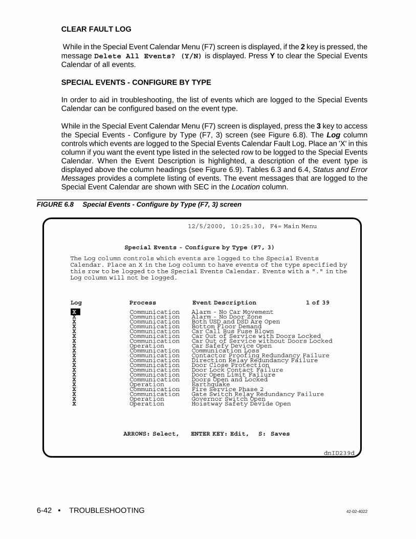
• TROUBLESHOOTING 42-02-40226-42
XXXXXXXXXXXXXXXXXXXX
CommunicationCommunicationCommunicationCommunicationCommunicationCommunicationCommunicationOperationCommunicationCommunicationCommunicationCommunicationCommunicationCommunicationCommunicationOperationCommunicationCommunicationOperationOperation
Alarm - No Car MovementAlarm - No Door ZoneBoth USD and DSD Are OpenBottom Floor DemandCar Call Bus Fuse BlownCar Out of Service with Doors LockedCar Out of Service without Doors LockedCar Safefy Device OpenCommunication LossContactor Proofing Redundancy FailureDirection Relay Redundancy FailureDoor Close ProtectionDoor Lock Contact FailureDoor Open Limit FailureDoors Open and LockedEarthquakeFire Service Phase 2Gate Switch Relay Redundancy FailureGovernor Switch OpenHoistway Safety Devide Open
12/5/2000, 10:25:30, F4= Main Menu
dnID239d
Special Events - Configure by Type (F7, 3)
The Log column controls which events are logged to the Special Events Calendar. Place an X in the Log column to have events of the type specified bythis row to be logged to the Special Events Calendar. Events with a "." in theLog column will not be logged.
Log Process Event Description 1 of 39
ARROWS: Select, ENTER KEY: Edit, S: Saves
CLEAR FAULT LOG
While in the Special Event Calendar Menu (F7) screen is displayed, if the 2 key is pressed, themessage Delete All Events? (Y/N) is displayed. Press Y to clear the Special EventsCalendar of all events.
SPECIAL EVENTS - CONFIGURE BY TYPE
In order to aid in troubleshooting, the list of events which are logged to the Special EventsCalendar can be configured based on the event type.
While in the Special Event Calendar Menu (F7) screen is displayed, press the 3 key to accessthe Special Events - Configure by Type (F7, 3) screen (see Figure 6.8). The Log columncontrols which events are logged to the Special Events Calendar Fault Log. Place an 'X' in thiscolumn if you want the event type listed in the selected row to be logged to the Special EventsCalendar. When the Event Description is highlighted, a description of the event type isdisplayed above the column headings (see Figure 6.9). Tables 6.3 and 6.4, Status and ErrorMessages provides a complete listing of events. The event messages that are logged to theSpecial Event Calendar are shown with SEC in the Location column.
FIGURE 6.8 Special Events - Configure by Type (F7, 3) screen
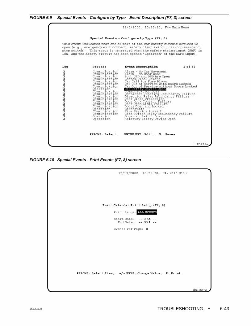
42-02-4022 TROUBLESHOOTING • 6-43
XXXXXXXXXXXXXXXXXXXX
CommunicationCommunicationCommunicationCommunicationCommunicationCommunicationCommunicationOperationCommunicationCommunicationCommunicationCommunicationCommunicationCommunicationCommunicationOperationCommunicationCommunicationOperationOperation
Alarm - No Car MovementAlarm - No Door ZoneBoth USD and DSD Are OpenBottom Floor DemandCar Call Bus Fuse BlownCar Out of Service with Doors LockedCar Out of Service without Doors LockedCar Safefy Device OpenCommunication LossContactor Proofing Redundancy FailureDirection Relay Redundancy FailureDoor Close ProtectionDoor Lock Contact FailureDoor Open Limit FailureDoors Open and LockedEarthquakeFire Service Phase 2Gate Switch Relay Redundancy FailureGovernor Switch OpenHoistway Safety Devide Open
12/5/2000, 10:25:30, F4= Main Menu
dnID239e
Special Events - Configure by Type (F7, 3)
This event indicates that one or more of the car safety circuit devices isopen (e.g., emergency exit contact, safety clamp switch, car-top emergency stop switch). This error is generated when the safety string input (SAF) islow, and the safety circuit has been opened "upstream" of the SAFC input.
Log Process Event Description 1 of 39
ARROWS: Select, ENTER KEY: Edit, S: Saves
12/19/2002, 10:25:30, F4= Main Menu
dnID272
Print Range: ALL EVENTS
Start Date: -- N/A -- End Date: -- N/A --
Events Per Page: 8
Event Calendar Print Setup (F7, 8)
ARROWS: Select Item, +/- KEYS: Change Value, P: Print
FIGURE 6.9 Special Events - Configure by Type - Event Description (F7, 3) screen
FIGURE 6.10 Special Events - Print Events (F7, 8) screen
• TROUBLESHOOTING 42-02-40226-44
Controller Online Success Rate
12/6/2000, 10:25:30, F4= Main Menu
dnID233a
Car A 100%YES
Network Status (F11, 1)
dnID227c
Diagnostics Menu (F11)
1 -
3 -
4 -
5 -
7 -
8 -
Network Status
Memory Dump
Task Info for CGP
Resource Usage
MP Input/Output
Car Performance
9/18/2002, 10:25:30 AM, F4=Main Menu
6.3 USING THE DIAGNOSTICS
System diagnostics are available using the optional CRT terminal with Release 4Communication software. Diagnostics are accessed via the Diagnostics Menu (F11) screen.
FIGURE 6.11 Diagnostics Menu (F11) screen
FIGURE 6.12 Network Status (F11, 1) screen
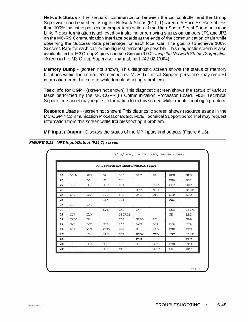
42-02-4022 TROUBLESHOOTING • 6-45
dnID265
MP Diagnostic Input/Output Flags
20
21
22
23
24
25
26
27
28
29
2A
2B
2C
2D
2E
2F
DOLM
DCF
INT
LFP
LLW
DNDO
DMD
TOS
SD
HLD
PHE
DC
DCP
FRA
UFP
DLK
LD
DCB
MLT
STC
SDA
DZ
UC
DOF
HSEL
FCS
HLW
EQI
UCB
PSTX
SAF
DSD
EQA
DOL
CC
LOT
CSB
FRS
HLI
IND
DZORDZ
DDP
CCB
MGR
HCR
BFD
ATSF
DBC
DCC
DNS
IN
UPDO
DMU
H
HCDX
FRM
SU
SE
HTC
NUDG
UPS
LU
DCA
REL
CCD
SUA
ECRN
GEU
DHO
CCT
STD
FWI
DEL
PK
UCA
DSH
ISV
USD
CD
GED
DOI
SDT
DSHT
STU
YSIM
LLI
UDP
CCA
RUN
ISRT
FRC
TFD
EPR
7/19/2000, 10:25:30 AM, F4=Main Menu
Network Status - The status of communication between the car controller and the GroupSupervisor can be verified using the Network Status (F11, 1) screen. A Success Rate of lessthan 100% indicates possible improper termination of the High-Speed Serial CommunicationLink. Proper termination is achieved by installing or removing shunts on jumpers JP1 and JP2on the MC-RS Communication Interface boards at the ends of the communication chain whileobserving the Success Rate percentage for each local Car. The goal is to achieve 100%Success Rate for each car, or the highest percentage possible. This diagnostic screen is alsoavailable on the M3 Group Supervisor (see Section 3.9.2 Using the Network Status DiagnosticsScreen in the M3 Group Supervisor manual, part #42-02-G004)
Memory Dump - (screen not shown) This diagnostic screen shows the status of memorylocations within the controller's computers. MCE Technical Support personnel may requestinformation from this screen while troubleshooting a problem.
Task Info for CGP - (screen not shown) This diagnostic screen shows the status of varioustasks performed by the MC-CGP-4(8) Communication Processor Board. MCE TechnicalSupport personnel may request information from this screen while troubleshooting a problem.
Resource Usage - (screen not shown) This diagnostic screen shows resource usage in theMC-CGP-4 Communication Processor Board. MCE Technical Support personnel may requestinformation from this screen while troubleshooting a problem.
MP Input / Output - Displays the status of the MP inputs and outputs (Figure 6.13).
FIGURE 6.13 MP2 Input/Output (F11,7) screen
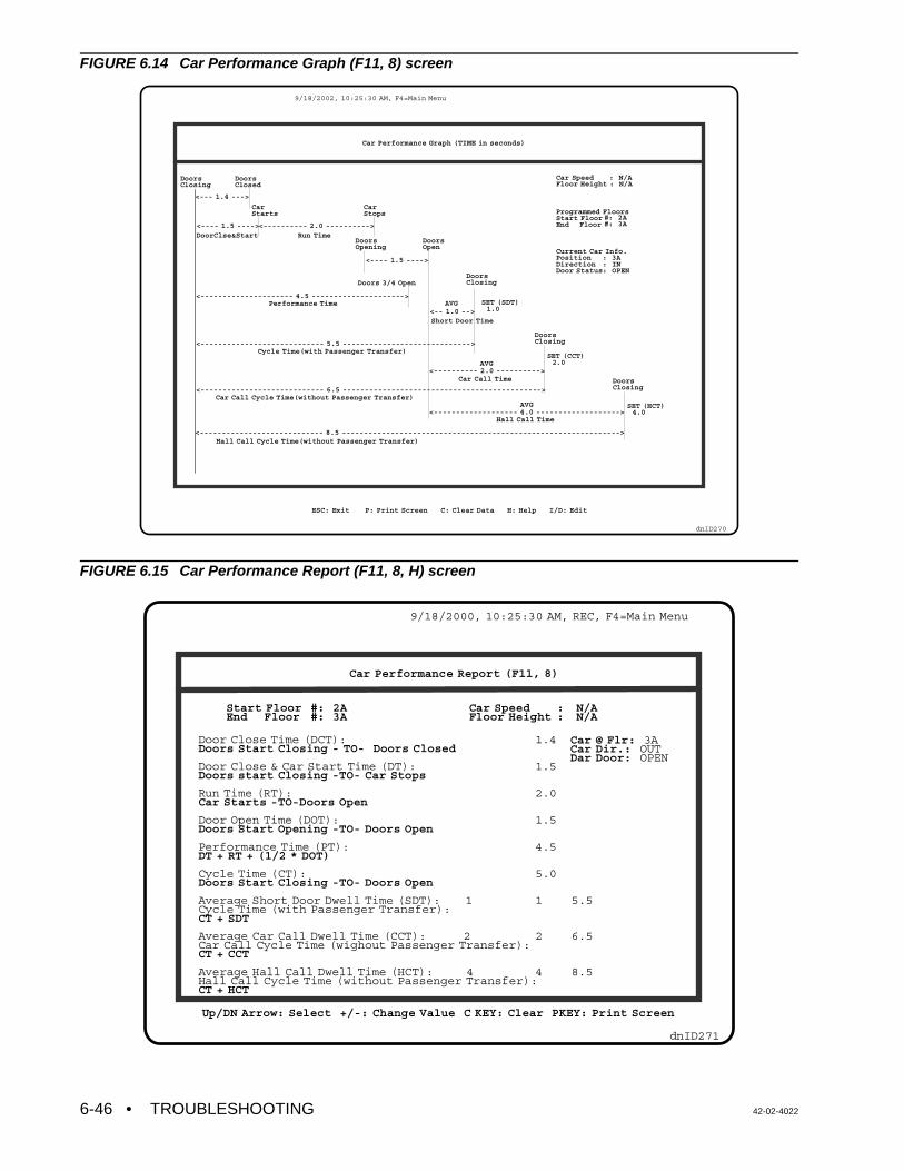
• TROUBLESHOOTING 42-02-40226-46
9/18/2002, 10:25:30 AM, F4=Main Menu
ESC: Exit P: Print Screen C: Clear Data H: Help I/D: Edit
dnID270
DoorsClosing
DoorsClosed
CarStarts
CarStops
Car Speed : N/AFloor Height : N/A
Programmed FloorsStart Floor End Floor
Current Car Info.Position Direction Door Status
DoorsOpening
DoorsOpen
#: 2A#: 3A
: 3A: IN: OPEN
DoorsClosing
DoorsClosing
DoorsClosing
SET (HCT) 4.0
SET (SDT) 1.0
AVG
AVG
AVG
SET (CCT) 2.0
<--- 1.4 --->
<---- 1.5 ---->
<---- 1.5 ---->
<-- 1.0 -->
<---------- 2.0 ---------->
<---------- 2.0 ---------->
<--------------------- 4.5 --------------------->
<------------------- 4.0 ------------------->
<---------------------------- 5.5 ----------------------------->
<---------------------------- 6.5 --------------------------------------------->
<---------------------------- 8.5 --------------------------------------------------------------->
Doors 3/4 Open
Performance Time
DoorClse&Start Run Time
Short Door Time
Car Call Time
Hall Call Time
Cycle Time(with Passenger Transfer)
Car Call Cycle Time(without Passenger Transfer)
Hall Call Cycle Time(without Passenger Transfer)
Car Performance Graph (TIME in seconds)
dnID271
Car Performance Report (F11, 8)
Up/DN Arrow: Select +/-: Change Value C KEY: Clear PKEY: Print Screen
Start FloorEnd Floor
#: 2A#: 3A
Car SpeedFloor Height
Car @ Flr: 3ACar Dir.: OUTDar Door: OPEN
: N/A: N/A
1.4
1.5
2.0
1.5
4.5
5.0
1 5.5
2 6.5
4 8.5
Door Close Time (DCT):Doors Start Closing - TO- Doors Closed
Door Close & Car Start Time (DT):Doors start Closing -TO- Car Stops
Run Time (RT):Car Starts -TO-Doors Open
Door Open Time (DOT):Doors Start Opening -TO- Doors Open
Performance Time (PT):DT + RT + (1/2 * DOT)
Cycle Time (CT):Doors Start Closing -TO- Doors Open
Average Short Door Dwell Time (SDT): 1Cycle Time (with Passenger Transfer):CT + SDT
Average Car Call Dwell Time (CCT): 2Car Call Cycle Time (wighout Passenger Transfer):CT + CCT
Average Hall Call Dwell Time (HCT): 4Hall Call Cycle Time (without Passenger Transfer):CT + HCT
9/18/2000, 10:25:30 AM, REC, F4=Main Menu
FIGURE 6.14 Car Performance Graph (F11, 8) screen
FIGURE 6.15 Car Performance Report (F11, 8, H) screen
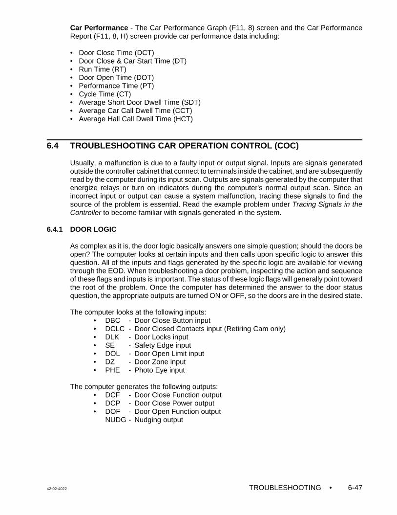
42-02-4022 TROUBLESHOOTING • 6-47
Car Performance - The Car Performance Graph (F11, 8) screen and the Car PerformanceReport (F11, 8, H) screen provide car performance data including:
• Door Close Time (DCT)• Door Close & Car Start Time (DT)• Run Time (RT)• Door Open Time (DOT)• Performance Time (PT)• Cycle Time (CT)• Average Short Door Dwell Time (SDT)• Average Car Call Dwell Time (CCT)• Average Hall Call Dwell Time (HCT)
6.4 TROUBLESHOOTING CAR OPERATION CONTROL (COC)
Usually, a malfunction is due to a faulty input or output signal. Inputs are signals generatedoutside the controller cabinet that connect to terminals inside the cabinet, and are subsequentlyread by the computer during its input scan. Outputs are signals generated by the computer thatenergize relays or turn on indicators during the computer's normal output scan. Since anincorrect input or output can cause a system malfunction, tracing these signals to find thesource of the problem is essential. Read the example problem under Tracing Signals in theController to become familiar with signals generated in the system.
6.4.1 DOOR LOGIC
As complex as it is, the door logic basically answers one simple question; should the doors beopen? The computer looks at certain inputs and then calls upon specific logic to answer thisquestion. All of the inputs and flags generated by the specific logic are available for viewingthrough the EOD. When troubleshooting a door problem, inspecting the action and sequenceof these flags and inputs is important. The status of these logic flags will generally point towardthe root of the problem. Once the computer has determined the answer to the door statusquestion, the appropriate outputs are turned ON or OFF, so the doors are in the desired state.
The computer looks at the following inputs:• DBC - Door Close Button input• DCLC - Door Closed Contacts input (Retiring Cam only)• DLK - Door Locks input• SE - Safety Edge input• DOL - Door Open Limit input• DZ - Door Zone input• PHE - Photo Eye input
The computer generates the following outputs:• DCF - Door Close Function output• DCP - Door Close Power output• DOF - Door Open Function output
NUDG - Nudging output
• TROUBLESHOOTING 42-02-40226-48
NOTE: If this installation has rear doors and at least one floor where bothopenings exist, look up the rear door zone flag (DZR). To do so, theDiagnostic On/Norm switch and the A5 switch must be up. All otherswitches are down. Diagnostic Indicator 6 shows the status of DZR.
TRACING SIGNALS IN THE CONTROLLER
The following example shows how an input signal can be traced from its source (field wire) toits destination inside the computer (EOD). Monitor the Door Zone (DZ) flag. The DZ flag canbe monitored using the Computer Swing Panel Diagnostic Indicators as described in Section5.4.1, Viewing the MC-MP2-2K Computer Variable Flags. The door flags can also be viewedon the MP2 Input/Output (F11, 7) screen (see Figure 6.13) Moving the car in the hoistwayshould cause this flag to turn ON and OFF whenever the car goes through a floor. If the flag(LED) does not turn ON and OFF, the following could be causing the problem.
1. Defective Door Zone sensor.2. Incorrect hoistway wiring. 3. Faulty termination of hoistway wiring to the (DZ) terminal inside the controller.4. Defect on the SC-SB2K or HC-PI/O board.
First, determine whether the problem is inside or outside the controller. With a voltmeter, probethe Door Zone terminal (27). This terminal is in Area 3 of the job prints. Moving the car in thehoistway should cause the voltmeter to read 120VAC when the car is in the door zone. If whenthe car passes through the door zone the voltmeter does not read 120VAC the problem isexternal to the controller (see items 1, 2, and 3 above). If the voltmeter does read 120VACwhen the car passes through the door zone the problem is internal to the controller (see item4 above). The job prints show the DZ signal goes to the right hand side of the DZ relay to a 47K1W resistor, to pin 8 of connector C2 on the SC-SB2K Relay board, and then to pin 8 ofconnector C2 on the HC-PI/O board.
Figures 6.16 and 6.17 show the HC-PI/O and SC-SB2K boards and the location of the DZsignal in the controller. Notice that if terminal 27 is powered, approximately 120VAC will bepresent at the bottom of the 47K 1W resistor corresponding to DZ. The top of the same resistorshould read about 5VAC with respect to COM.
The SC-SB2K board has test pads on the front of the board which surround every relay andconnector. Relays IN2 and SAFR1 each have a legend that indicates which pad correspondsto which contact or its coil on this board. To be sure that the input from terminal 27 is makingits way to the relay coil, probe the test pad on the lower right hand side of the DZ relay.
It is not necessary to remove the relay or get to the back of the SC-SB2K board to trace signalson the board. Signals can be traced on the HC-PI/O board. If the signal gets to the HC-PI/Oboard but does not get to the computer, it is safe to assume that the problem is on the HC-PI/Oboard.
Important computer-generated logic flags:• CCT - Car Call Time flag • DOI - Door Open Intent flag • DSH - Door Shortening (Intermediate) flag • DSHT - Door Shortening (Final) flag • HCT - Hall Call Time flag • LOT - Lobby Time flag • SDT - Short Door Time flag
42-02-4022 TROUBLESHOOTING • 6-49
Using the logic flags listed above, the computer makes a decision regarding the doors. TheDoor Open Intent flag's (DOI) status reflects the computer's decision. If the computerrecognizes the necessity of either opening the doors or keeping the doors open, this flag willcome ON. This flag can be found using the EOD. When viewing this flag, the correspondingDiagnostic Indicator will turn ON when the computer decides that the doors should be open.
The DOI flag is a useful flag to inspect when troubleshooting door problems. Remember if DOIis ON, it will turn the DOF output ON which should pick the DO relay. The door should stayopen until the DOL (Door Open Limit) turns OFF. The absence of DOL will turn the DOF outputOFF. DOI will remain ON for the door dwell time (CCT, HCT, etc.). When DOI turns OFF, theDCF output turns ON and the DC relay will close the car doors. The signal that turns the DCFoutput OFF is DLK (Doors Locked) or possibly DCLC if the car has a retiring cam. After thedoors are locked there is approximately a two-second delay before the DCF output turns OFF.
If there is a demand for the car (as is evidenced by the DMU or DMD flags being on) and if theDOI flag is not ON, then the DCP (Door Close Power) output will be turned ON regardless ofthe position of the door. The DCP output is used to provide door closing power while the carruns through the hoistway for those door operators requiring it, such as those made by theG.A.L. corporation.
If the doors get stuck because the door interlock keeper failed to lift high enough to clear thedoor interlock during the opening cycle, then the doors cannot complete opening, which coulddamage the door motor. The Door Open Protection Timer will eventually stop trying to open thedoors and the car will then go on to the next call. Similarly, if the doors do not close all the way,the computer recycles the doors at a programmed interval in an attempt to clear the problem.
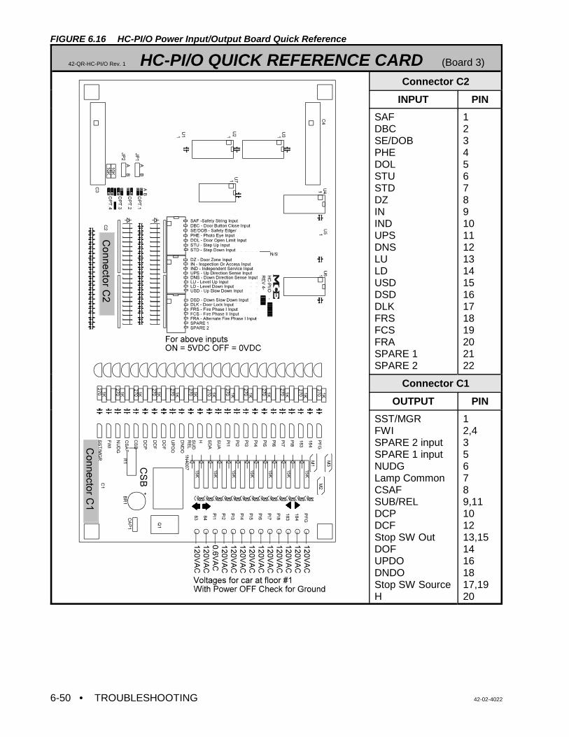
• TROUBLESHOOTING 42-02-40226-50
FIGURE 6.16 HC-PI/O Power Input/Output Board Quick Reference
42-QR-HC-PI/O Rev. 1 HC-PI/O QUICK REFERENCE CARD (Board 3)
Connector C2
INPUT PIN
SAFDBCSE/DOBPHEDOLSTUSTDDZININDUPSDNSLULDUSDDSDDLKFRSFCSFRASPARE 1SPARE 2
12345678910111213141516171819202122
Connector C1
OUTPUT PIN
SST/MGRFWISPARE 2 input SPARE 1 inputNUDGLamp CommonCSAFSUB/RELDCPDCFStop SW OutDOFUPDODNDOStop SW SourceH
12,4356789,11101213,1514161817,1920
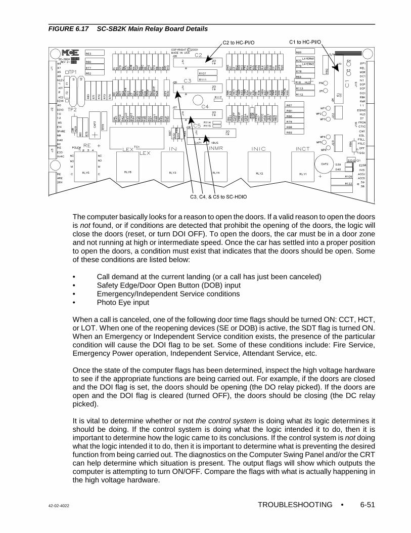
42-02-4022 TROUBLESHOOTING • 6-51
FIGURE 6.17 SC-SB2K Main Relay Board Details
The computer basically looks for a reason to open the doors. If a valid reason to open the doorsis not found, or if conditions are detected that prohibit the opening of the doors, the logic willclose the doors (reset, or turn DOI OFF). To open the doors, the car must be in a door zoneand not running at high or intermediate speed. Once the car has settled into a proper positionto open the doors, a condition must exist that indicates that the doors should be open. Someof these conditions are listed below:
• Call demand at the current landing (or a call has just been canceled)• Safety Edge/Door Open Button (DOB) input• Emergency/Independent Service conditions • Photo Eye input
When a call is canceled, one of the following door time flags should be turned ON: CCT, HCT,or LOT. When one of the reopening devices (SE or DOB) is active, the SDT flag is turned ON.When an Emergency or Independent Service condition exists, the presence of the particularcondition will cause the DOI flag to be set. Some of these conditions include: Fire Service,Emergency Power operation, Independent Service, Attendant Service, etc.
Once the state of the computer flags has been determined, inspect the high voltage hardwareto see if the appropriate functions are being carried out. For example, if the doors are closedand the DOI flag is set, the doors should be opening (the DO relay picked). If the doors areopen and the DOI flag is cleared (turned OFF), the doors should be closing (the DC relaypicked).
It is vital to determine whether or not the control system is doing what its logic determines itshould be doing. If the control system is doing what the logic intended it to do, then it isimportant to determine how the logic came to its conclusions. If the control system is not doingwhat the logic intended it to do, then it is important to determine what is preventing the desiredfunction from being carried out. The diagnostics on the Computer Swing Panel and/or the CRTcan help determine which situation is present. The output flags will show which outputs thecomputer is attempting to turn ON/OFF. Compare the flags with what is actually happening inthe high voltage hardware.
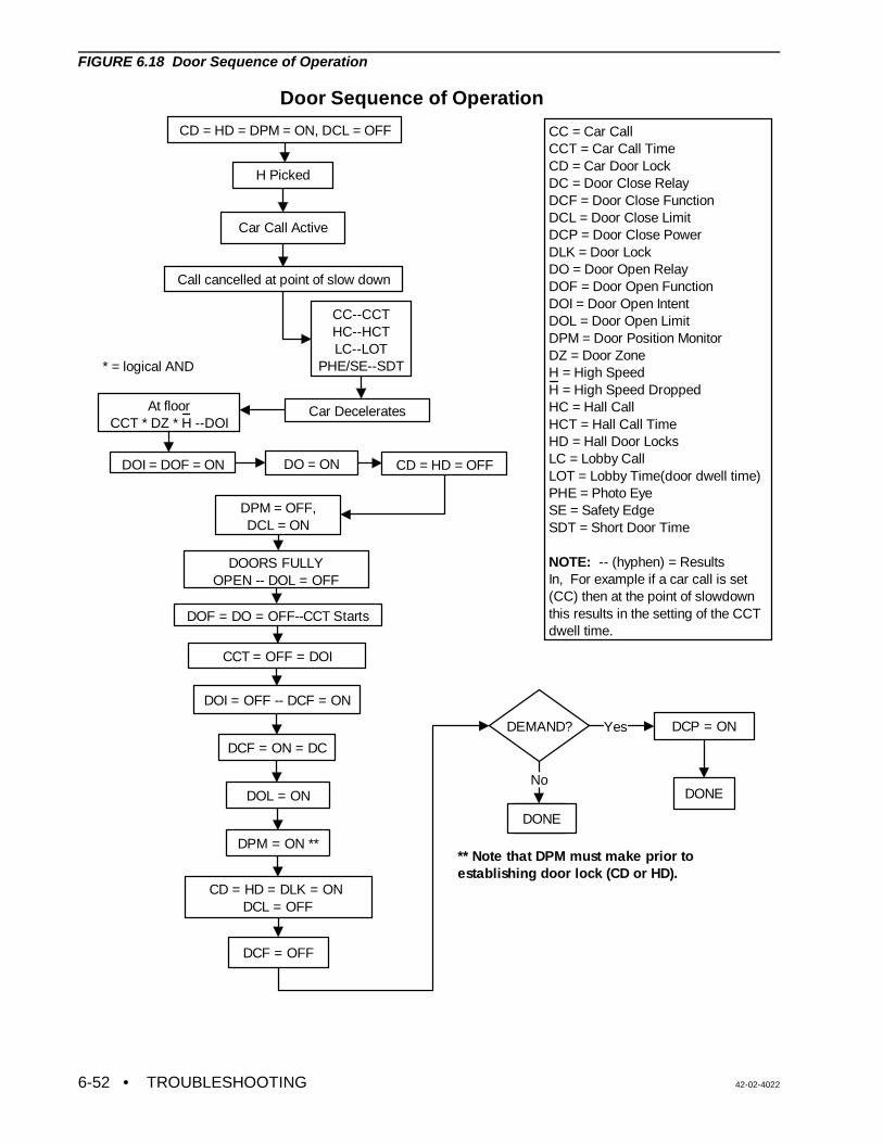
• TROUBLESHOOTING 42-02-40226-52
H Picked
Car Call Active
Call cancelled at point of slow down
CC--CCTHC--HCTLC--LOT
PHE/SE--SDT
Car DeceleratesAt floorCCT * DZ * H --DOI
DOI = DOF = ON
DOF = DO = OFF--CCT Starts
CCT = OFF = DOI
DEMAND?
DONE
DOI = OFF -- DCF = ON
DCF = ON = DC
CD = HD = DLK = ON DCL = OFF
DCF = OFF
DCP = ON
DONE
CC = Car CallCCT = Car Call TimeCD = Car Door LockDC = Door Close RelayDCF = Door Close FunctionDCL = Door Close LimitDCP = Door Close PowerDLK = Door LockDO = Door Open RelayDOF = Door Open FunctionDOI = Door Open IntentDOL = Door Open LimitDPM = Door Position MonitorDZ = Door ZoneH = High SpeedH = High Speed DroppedHC = Hall CallHCT = Hall Call TimeHD = Hall Door LocksLC = Lobby CallLOT = Lobby Time(door dwell time)PHE = Photo EyeSE = Safety EdgeSDT = Short Door Time
NOTE: -- (hyphen) = Results In, For example if a car call is set (CC) then at the point of slowdown this results in the setting of the CCT dwell time.
CD = HD = DPM = ON, DCL = OFF
CD = HD = OFFDO = ON
DPM = OFF,DCL = ON
DOORS FULLY OPEN -- DOL = OFF
** Note that DPM must make prior to establishing door lock (CD or HD).
Door Sequence of Operation
DPM = ON **
Yes
* = logical AND
DONE
NoDOL = ON
FIGURE 6.18 Door Sequence of Operation
42-02-4022 TROUBLESHOOTING • 6-53
Door Closing Sequence,Timing and Fault Generation
Doors open
DOL = 0DLK = 0
CD = HD = 0DPM = 0 DCL = 120
DPM Redun FLT
No
Yes
DCL Redun FLT
NoInitiate Close
Sequence
DCF = ONDC picks
DOL = 120
Yes
DLK=120
60 sec?
Door Close
Prot FLT
No
Yes
CD=120
DPM=120 1.0 Sec?No Yes
Keep DCF = ON for 2.0 more Sec.
Demand?
DCP = ON
EndNo
Yes
During DC we check to see if the status of inputs DCL, DPM, CD, HD, DOLand DLK make sense. Clearly, if DLK is ON (120V), DCL must be OFF (0V). We also allow time for the various contacts to make up (debounce). Important Note: DPM should make about 1" to 2" from full door close.
HD=120Yes
1.0 Sec?
DLK Redun FLT
No
Yes
NoDLK=120
No No
No
0.5 Sec 0.5 Sec
YesEnd
Yes
DPM=120 1.0 Sec?DPM
Redun FLT
No
No
Yes
Yes
No
Yes
No
waiting for DPM
waiting for DPM
Waiting forDLK
Waiting forDLK
End
CD or HD Redun FLT
FIGURE 6.19 Door Closing Sequence, Timing and Fault Generation Flowchart
• TROUBLESHOOTING 42-02-40226-54
NOTE: If the controller is equipt with the SmartLink for Car Operating Panel option,see Appendix G, Option SmartLink for Car Operating Panel, fortroubleshooting information.
Door Operation Timing Diagram
Start with door fully open... , ³ Doors start to open
DOF $$$$$$$$$$$$$$$$$$$$$$$$$$$$$$$$$$$$$$$$$$$$$,&&&&&&&&&&,$$$
DCF $$,&&&&&&&&&&&&&&&&&&&&&&&,$$$$$$$$$$$$$$$$$$$$$$$$$$$$
, ³ Doors start to close DOL $$$$$,&&&&&&&&&&&&&&&&&&&&&&&&&&&&&&&&&&&&&&&&&&,$$
DCL &&&&&&&&&&&&,$$$$$$$$$$$$$$$$$$$$$$$$$$$$$$$$$,&&&&&&&&&
, ³DPM established well before door lock DPM $$$$$$$$$$$$$,&&&&&&&&&&&&&&&&&&&&&&&&&&&&&&,$$$$$$$$$
,³Door lock established CD $$$$$$$$$$$$$$$$$,&&&&&&&&&&&&&&&&&&&&&&&&,$$$$$$$$$$$$$
HD $$$$$$$$$$$$$$$$$,&&&&&&&&&&&&&&&&&&&&&&&&,$$$$$$$$$$$$$
DLK $$$$$$$$$$$$$$$$$,&&&&&&&&&&&&&&&&&&&&&&&&,$$$$$$$$$$$$$
0 ² !!!Closing !! ÷ 0 ²SSS !!!!!!! Idle S!!!!!!!!!÷ 0 ²! Opening !÷ 0
6.4.2 CALL LOGIC - NORMAL OPERATION
Calls are input to the system by grounding the appropriate call input, as labeled on the CallInput/Output board (Figure 6.20, HC-CI/O Call Input/Output Board Quick Reference). The actof physically grounding the call input terminal turns on the corresponding LED on the Callboard. Recognition and acceptance of the call by the computer will cause the indicator toremain lit on the board. Cancellation of the call turns the indicator off. The single input/outputterminal on the Call board accepts call inputs from the call fixture pushbuttons, and also servesas the output terminal illuminating the call fixtures to indicate registration of a call. This meansthat the field wiring is identical to that used for a standard relay controller.
The computer may intentionally block call registration. When the computer prevents car callregistration, it turns ON the Car Call Disconnect flag (CCD) for that car. Inspection of this flagin the diagnostics (ADDR 2C, Diagnostic Indicator #3) will tell if the computer is preventing theacceptance of calls. If the CCD flag is ON, the reason for this condition must be discovered.CCD condition is caused by: Fire Service, motor limit timer elapsed, bottom or top floordemand, etc.
A corresponding flag exists for hall call registration prevention. The computer may detectconditions that prevent hall calls from registering, and set the Hall Call Disconnect Flag(HCDX). This is a system flag (as opposed to a per car flag) but is available for viewing in thediagnostic display along with each car's operating flags. There are many reasons for thecomputer to reject hall call registration: Fire service, a hall call bus problem, no available carsin service to respond to hall calls, etc.
If a call circuit becomes damaged or simply stuck ON as the result of a stuck push-button, theelevator will release itself from the stuck call automatically. If the pushbutton remains stuck, thecar will stop at the floor each time it passes. Again, the computer will release itselfautomatically, thereby allowing continued service in the building.
42-02-4022 TROUBLESHOOTING • 6-55
NOTE: Call terminal voltage must be $ 85% of call supply voltage.Example: If supply is 100VAC, terminal voltage may be 85VAC to
100VAC. 80VAC is insufficient.
6.4.3 TROUBLESHOOTING THE CALL CIRCUITS
If there is a problem with a call, first disconnect the field wire or wires from that call terminal todetermine if the problem is on the board or in the hoistway wiring or fixtures. Disconnect thecalls by unplugging the terminals, or removing individual wires. If the individual field wire isdisconnected, lightly tighten the screw terminal since it may not make contact if an attempt ismade to ground the terminal using a jumper when the screw on the terminal is loose.
TABLE 6.5 Call Board Troubleshooting
Problem Recommended steps to resolve the problem
Call Terminal Voltageis insufficient
1. Turn OFF the power and remove the resistor fuse associated with thatterminal.
2. Turn ON the power and check terminal voltage again.3. If no voltage is present on the terminal:
a. Check the jumper plug (header) on the HC-CI/O Call board. Thejumper plug socket is located on the right hand side near the callindicators. If a Call board is replaced, this jumper plug must betransferred to the new board and stay in the same board position (morethan one Call board on the controller).
b. Verify that the correct incoming power is on terminals marked PS1, PS2and PS3. NOTE: Power will exist on at least one and possibly more ofthese terminals.
Call LED is ON eventhough the field wire isremoved
1. Reset the computer (Computer Reset pushbutton on Swing Panel). 2. Run the car to the nearest landing to reset PI. 3. It may be necessary to reset the computer in the Group Supervisor in order
to reset a latched hall call.4. If the call does not cancel under these conditions--replace the call board
Cannot register a hallcall at the call board
To discover whether the problem is with the call board or the field wiring: 1. First remove the resistor fuse and disconnect the field wire(s). 2. Verify that the HCDD, Hall Call Disconnect Computer Variable Flag is OFF
(Address 2C, LED 6).3. Verify that there is proper voltage on the call terminal. 4. Register a call by shorting the call terminal to terminal 1 or GND and verify
with EOD as described in Section 5.4.3, Viewing and Entering Calls (the callregistered light on the call board may not work correctly).
5. If the call does not register under these conditions--replace the call board.6. If the call circuit works with field wires removed, before connecting wires,
jumper the wire(s) to ground or terminal 1 and press the call pushbutton. If afuse blows, there is a field wiring problem. If connecting the call wirescauses a problem, the call board may be damaged.
Call remains latchedeven though the cararrives at that landing
Remove the associated resistor fuse. If the call cancels, replace the bad resistorfuse.
• TROUBLESHOOTING 42-02-40226-56
FIGURE 6.20 HC-CI/O Call Input/Output Board Quick Reference
42-QR-HC-CI/O Rev. 2 HC-CI/O QUICK REFERENCE CARD (BOARD 2)
42-02-4022 TROUBLESHOOTING • 6-57
NOTE: Before troubleshooting the call indicators, ensure that the call circuit isworking correctly, the field wires are connected and the resistor fuses areplugged in. If the board is arranged for neon (or LED) indicators(HC-CI/O-N), the board indicators are not affected by the fixture bulbs.
6.4.4 TROUBLESHOOTING THE CALL INDICATORS
When working correctly, a call indicator glows brightly when a call is registered and glows dimlyor not at all when a call is not registered.
TABLE 6.6 Call Indicator Troubleshooting
Problem Recommended steps to resolve the problem
With a call registered, the CallIndicator is dimly lit (Call Boardis HC-CI/O)
Incandescent bulb in the fixture for the call is burned out ormissing. Replace the bulb.
Indicator glows bright whetheror not there is a call registered
Bad triac or triac driver transistor. Check triac with power OFFand field wire removed. Failed triac usually measures a shortcircuit from the metal back (collector) to terminal 1. If board isnot in system, measure short between metal back and padarea around mounting hole. Be careful, the metal back of thetriac is connected to AC when power is ON. NOTE: bottomtriac corresponds to bottom terminal.
6.5 PC BOARD QUICK REFERENCES
This section contains a quick reference for the PC boards found in the typical VFMC-1000Series M controller. They are as follows:
• Standard Board Layout . . . . . . . . . . . . . . . . . . . . . . . . . . . . . . . . . . . . . . . . Figure 6.21• MC-MP2 Main Processor Board Quick Reference . . . . . . . . . . . . . . . . Figure 6.22• HC-PI/O Power Input/Output Board Quick Reference . Figure 6.16 in Section 6.4.1• HC-CI/O Call Input/Output Board Quick Reference . . . Figure 6.20 in Section 6.4.2• MC-CGP-4 Communication Processor Board Quick Reference . . . . . . . Figure 6.23• MC-RS Communication Interface Board Quick Reference . . . . . . . . Figure 6.24• SC-SB2K Main Safety Relay Board . . . . . . . . . . . . . . . . . . . . . . . . . . . Figure 6.25• SC-HDIO High Density I/O Board . . . . . . . . . . . . . . . . . . . . . . . . . . . . . Figure 6.26• SC-BASE Lock Bypass, Access, Overspeed, Emergency Brake Bd . . . Figure 6.27• SC-BASER Lock Bypass, Access, Overspeed, Emergency Brake board
with Rear Doors . . . . . . . . . . . . . . . . . . . . . . . . . . . . . . . . . . Figure 6.28• HC-ACI-D Drive Interface Board Quick Reference . . . . . . . . . . . . . . . . Figure 6.29• HC-ACIF Additional Drive Interface Board . . . . . . . . . . . . . . . . . . . . . . Figure 6.30
• TROUBLESHOOTING 42-02-40226-58
FIGURE 6.21 Standard Board Layout
42-02-4022 TROUBLESHOOTING • 6-59
FIGURE 6.22 MC-MP2 Main Processor Board Quick Reference
42-02-MC-MP2-2K MC-MP2-2K QUICK REFERENCE
JUMPER TYPICAL SETTING DESCRIPTION
JP5 see DescriptionN/C = Car ControllerA pins 1 & 2 = M3 Group Supervisor
JP6 N/C Jumper not loaded
JP9 AA = 27C020 or MC27C2001 EPROMB = 27C512, 27C010 or MC27C1001EPROM
JP10 N/C Jumper not loaded
JP11 AA = SRAM A16 Bank select enabled, B = Bank selectdisabled
JP12 AA = ROM A17 Bank select enabled, B = Bank selectdisabled
JP13 AA = ROM A16 Bank select enabled, B = Bank selectdisabled
• TROUBLESHOOTING 42-02-40226-60
FIGURE 6.23 MC-CGP-4 Communication Processor Board Quick Reference
42-QR-MC-CGP Rev 3 MC-CGP-x QUICK REFERENCE CARD
JUMPER TABLE
JUMPER CGP CGP-4CGP-8 DESCRIPTION
JP1 A A Communication Clock Rate: set to A if JP4 = B, set to B if JP3 = A or B or if JP4 = A.
JP2 ON ON Master Clock Rate: ON = Enabled, N/C = Disabled. Set to ON if JP4 = B. Set to N/C if JP3 = A or B or if JP4 = A.
JP3 N/C N/C Communication Clock: A = 16 MHz, B = 4 MHz (if JP3 = A or B, JP4 must = N/C).
JP4 B B Communication Clock: A = 8 MHz, B = 2 MHz (if JP4 = A or B, JP3 must = N/C).
JP5 B B This jumper relates to the I/O Bus Connector (J5), which is currently not used. I/O Connector J5 Pin 38 function: A = i960 Interrupt INT3# input, B = IO_CS1# output.
JP6 B B EPROM Size (27Cxxx): set to A for xxx = 512, set to B for xxx = 010, 020, 040 or 080.
JP7 A A Off Board Reset Signal: A = Enabled, B = Disabled.
JP8 A or hardwired
A or hardwired
EPROM Size (27Cxxx): set to A for xxx = 010, 020, 040 or 080, set to B for xxx = 512.
JP9 B B EPROM or Flash Memory: A = Flash, B = EPROM.
JP10 B B EPROM or Flash Memory: A = Flash, B = EPROM.
JP11 B or hardwired
B or hardwired
SRAM Size (68xxx): set to A for 1Mb SRAM, set to B for 4Mb SRAM.
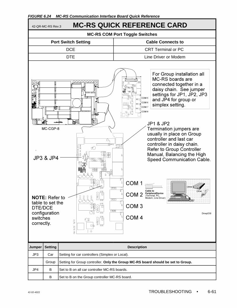
42-02-4022 TROUBLESHOOTING • 6-61
FIGURE 6.24 MC-RS Communication Interface Board Quick Reference
42-QR-MC-RS Rev.3 MC-RS QUICK REFERENCE CARD MC-RS COM Port Toggle Switches
Port Switch Setting Cable Connects to
DCE CRT Terminal or PC
DTE Line Driver or Modem
Jumper Setting Description
JP3 Car Setting for car controllers (Simplex or Local).
Group Setting for Group controller. Only the Group MC-RS board should be set to Group.
JP4 B Set to B on all car controller MC-RS boards.
B Set to B on the Group controller MC-RS board.
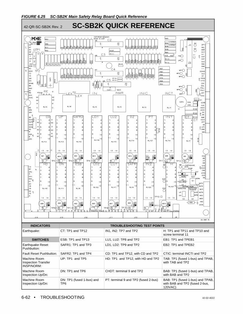
• TROUBLESHOOTING 42-02-40226-62
FIGURE 6.25 SC-SB2K Main Safety Relay Board Quick Reference
42-QR-SC-SB2K Rev. 2 SC-SB2K QUICK REFERENCE
INDICATORS TROUBLESHOOTING TEST POINTS
Earthquake: CT: TP1 and TP12 IN1, IN2: TP7 and TP2 H: TP1 and TP11 and TP10 andscrew terminal 11
SWITCHES ESB: TP1 and TP13 LU1, LU2: TP8 and TP2 EB1: TP1 and TPEB1
Earthquake ResetPushbutton:
SAFR1: TP1 and TP3 LD1, LD2: TP9 and TP2 EB2: TP1 and TPEB2
Fault Reset Pushbutton: SAFR2: TP1 and TP4 CD: TP1 and TP12, with CD and TP2 CTIC: terminal INCTI and TP2
Machine RoomInspection TransferINSP/NORM:
UP: TP1 and TP5 HD: TP1 and TP12, with HD and TP2 TAB: TP1 (fused 1-bus) and TPAB,with TAB and TP2
Machine RoomInspection Up/Dn:
DN: TP1 and TP6 CHDT: terminal 9 and TP2 BAB: TP1 (fused 1-bus) and TPAB,with BAB and TP2
Machine RoomInspection Up/Dn:
DN: TP1 (fused 1-bus) andTP6
PT: terminal 9 and TP2 (fused 2-bus) BAB: TP1 (fused 1-bus) and TPAB,with BAB and TP2 (fused 2-bus,120VAC)
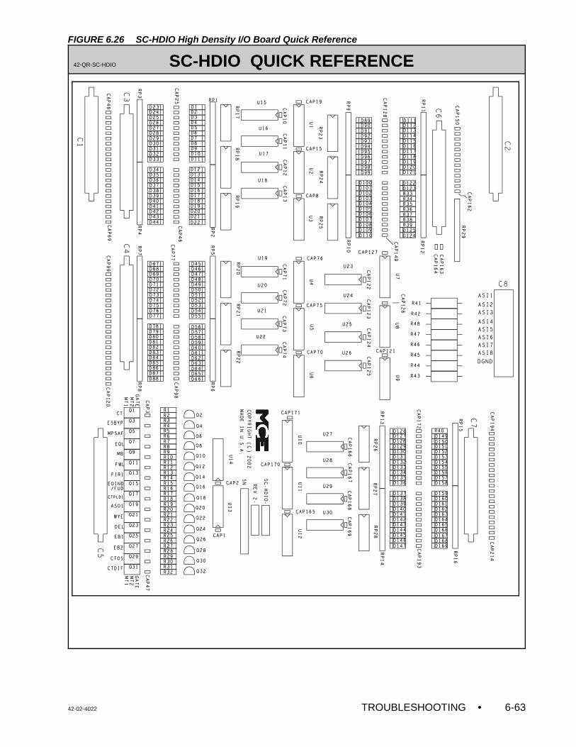
42-02-4022 TROUBLESHOOTING • 6-63
FIGURE 6.26 SC-HDIO High Density I/O Board Quick Reference
42-QR-SC-HDIO SC-HDIO QUICK REFERENCE
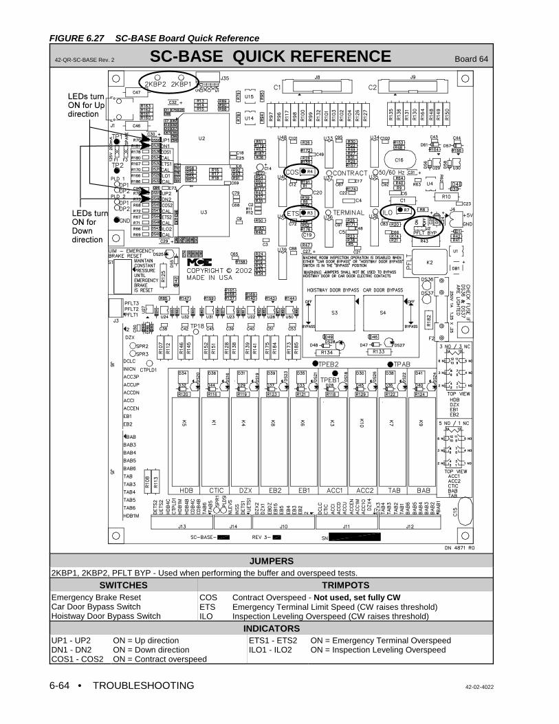
• TROUBLESHOOTING 42-02-40226-64
FIGURE 6.27 SC-BASE Board Quick Reference
42-QR-SC-BASE Rev. 2 SC-BASE QUICK REFERENCE Board 64
JUMPERS2KBP1, 2KBP2, PFLT BYP - Used when performing the buffer and overspeed tests.
SWITCHES TRIMPOTSEmergency Brake ResetCar Door Bypass SwitchHoistway Door Bypass Switch
COS Contract Overspeed - Not used, set fully CWETS Emergency Terminal Limit Speed (CW raises threshold)ILO Inspection Leveling Overspeed (CW raises threshold)
INDICATORSUP1 - UP2DN1 - DN2COS1 - COS2
ON = Up directionON = Down directionON = Contract overspeed
ETS1 - ETS2ILO1 - ILO2
ON = Emergency Terminal OverspeedON = Inspection Leveling Overspeed
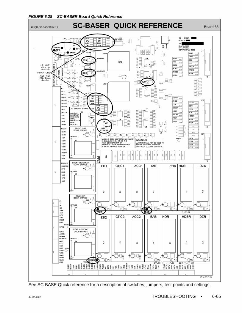
42-02-4022 TROUBLESHOOTING • 6-65
FIGURE 6.28 SC-BASER Board Quick Reference
42-QR-SC-BASER Rev. 2 SC-BASER QUICK REFERENCE Board 66
See SC-BASE Quick reference for a description of switches, jumpers, test points and settings.
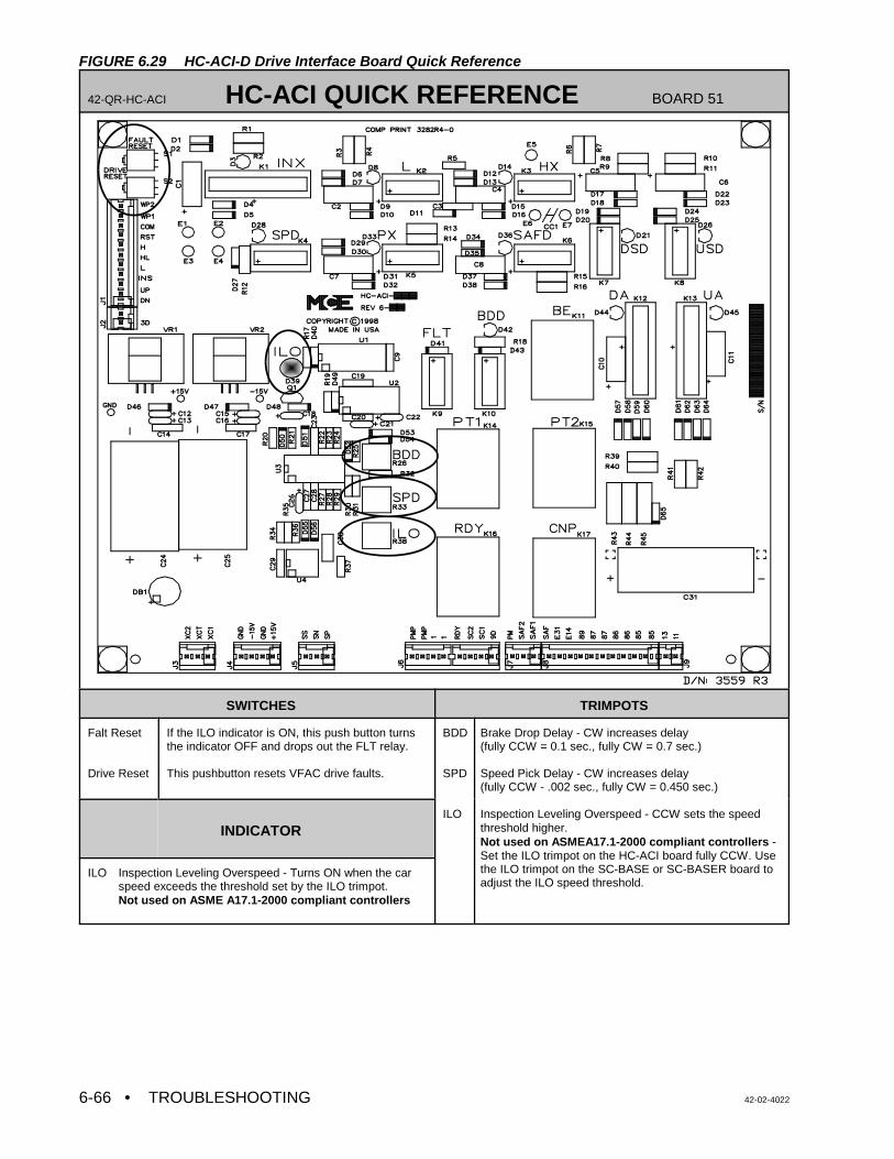
• TROUBLESHOOTING 42-02-40226-66
FIGURE 6.29 HC-ACI-D Drive Interface Board Quick Reference
42-QR-HC-ACI HC-ACI QUICK REFERENCE BOARD 51
SWITCHES TRIMPOTS
Falt Reset
Drive Reset
If the ILO indicator is ON, this push button turnsthe indicator OFF and drops out the FLT relay.
This pushbutton resets VFAC drive faults.
BDD
SPD
ILO
Brake Drop Delay - CW increases delay(fully CCW = 0.1 sec., fully CW = 0.7 sec.)
Speed Pick Delay - CW increases delay (fully CCW - .002 sec., fully CW = 0.450 sec.)
Inspection Leveling Overspeed - CCW sets the speedthreshold higher. Not used on ASMEA17.1-2000 compliant controllers - Set the ILO trimpot on the HC-ACI board fully CCW. Usethe ILO trimpot on the SC-BASE or SC-BASER board toadjust the ILO speed threshold.
INDICATOR
ILO Inspection Leveling Overspeed - Turns ON when the carspeed exceeds the threshold set by the ILO trimpot.Not used on ASME A17.1-2000 compliant controllers
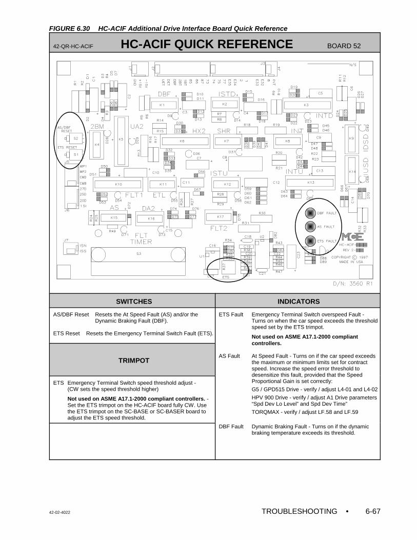
42-02-4022 TROUBLESHOOTING • 6-67
FIGURE 6.30 HC-ACIF Additional Drive Interface Board Quick Reference
42-QR-HC-ACIF HC-ACIF QUICK REFERENCE BOARD 52
SWITCHES INDICATORS
AS/DBF Reset Resets the At Speed Fault (AS) and/or theDynamic Braking Fault (DBF).
ETS Reset Resets the Emergency Terminal Switch Fault (ETS).
ETS Fault Emergency Terminal Switch overspeed Fault -Turns on when the car speed exceeds the thresholdspeed set by the ETS trimpot.
Not used on ASME A17.1-2000 compliantcontrollers.
AS Fault At Speed Fault - Turns on if the car speed exceedsthe maximum or minimum limits set for contractspeed. Increase the speed error threshold todesensitize this fault, provided that the SpeedProportional Gain is set correctly:
G5 / GPD515 Drive - verify / adjust L4-01 and L4-02
HPV 900 Drive - verify / adjust A1 Drive parameters“Spd Dev Lo Level” and Spd Dev Time”
TORQMAX - verify / adjust LF.58 and LF.59
DBF Fault Dynamic Braking Fault - Turns on if the dynamicbraking temperature exceeds its threshold.
TRIMPOT
ETS Emergency Terminal Switch speed threshold adjust -(CW sets the speed threshold higher)
Not used on ASME A17.1-2000 compliant controllers. -Set the ETS trimpot on the HC-ACIF board fully CW. Usethe ETS trimpot on the SC-BASE or SC-BASER board toadjust the ETS speed threshold.
• TROUBLESHOOTING 42-02-40226-68
NOTE: The drive software has been modified for this application. Some of theparameters in the parameter sheet are different and are not available in thedrive manual. If a drive has been replaced in the field, all of the driveparameters should be entered manually and should be verified accordingto the parameter sheet shipped with the controller.
6.6 TROUBLESHOOTING THE DSD 412 SCR DRIVE
6.6.1 IF THE CAR DOES NOT MOVE ON INSPECTION
Pick or Picked = relay energizedDrop or dropped = relay de-energized
If the car does not move on INSPECTION, check the following:
1. Verify that the M contactor, relays BK & SAFR2 and the brake pick when the directionrelays, U or D, are picked. If M, BK and SAFR2 do not pick, check the related circuit asshown in the controller drawings. Relays CNP and RDY on the HC-ACI-D board shouldalso be ON. These relays will turn OFF if there is a drive fault.
Verify that relays PT1 and PT2 on the HC-ACI-D board and MP1, MP2, LPR & LPRM,(UAX, UAXD or DAX, DAXD) in the controller pick when the direction is picked. If theserelays are not picked, check for 120VAC on terminals 9, 10 and 12 on the SC-SB2KMain Relay Board. If there is no voltage on these terminals, refer to the controllerdrawings to find the problem.
2. Verify that relays CNP and RDY are picked. If relay RDY is not picked then check thedrive keypad to see if there is a drive fault. If there is no fault in the drive unit, check thewiring for the RDY circuit. Relays PT1, PT2, UA or DA on the HC-ACI-D board shouldpick when the direction relays are picked. If the relays are not picking, check for 36VACbetween terminals XC1, XC2 and +15 and -15 on the HC-ACI-D board. If there is novoltage, check the fuse on the primary side of the 30 VA transformer shown in drawing-3 of the job prints. Also check the wiring from the secondary of the same transformerto terminal XC1, XC2 on the HC-ACI-D board.
Verify that the drive receives the Field Enable (TB1-9), direction (TB1- 8 or 50),inspection speed command (TB1-54) and Loop contactor confirm (TB1-7) inputs. Tocheck these signals, measure the DC voltage on the above terminals with respect to
TB1- 44 (24 VDC = ON, 0 VDC = OFF).
The Ready and Run Green LED on the drive key pad should turn ON, Parameter 602value should display the commanded inspection speed when direction is picked.
If all the functions described in the above steps are working properly and the car stilldoes not move, verify the drive parameters and compare them with the drive parametersheet which was shipped with the controller. The motor name plate values should matchthe entered motor parameters. Some of the following parameters, if not set properly,can prevent the car from moving on Inspection.
4. If the car moves in the reverse direction or trips a Fault 98: Refer to section 3.4 (g)
If the parameters are set to the correct values and the Motor Armature, Motor Field and Brakeconnections are correct, and if the car still does not move on inspection, call MCE TechnicalSupport.
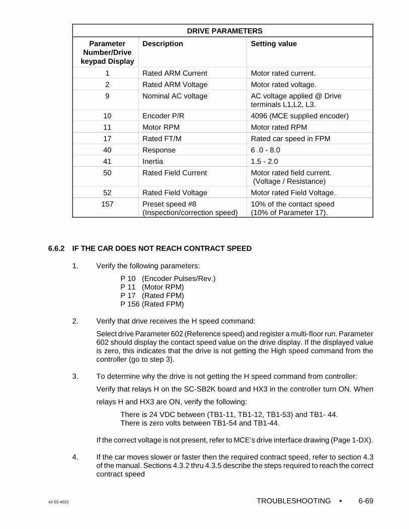
42-02-4022 TROUBLESHOOTING • 6-69
DRIVE PARAMETERS
ParameterNumber/Drive
keypad Display
Description Setting value
1 Rated ARM Current Motor rated current.
2 Rated ARM Voltage Motor rated voltage.
9 Nominal AC voltage AC voltage applied @ Driveterminals L1,L2, L3.
10 Encoder P/R 4096 (MCE supplied encoder)
11 Motor RPM Motor rated RPM
17 Rated FT/M Rated car speed in FPM
40 Response 6 .0 - 8.0
41 Inertia 1.5 - 2.0
50 Rated Field Current Motor rated field current. (Voltage / Resistance)
52 Rated Field Voltage Motor rated Field Voltage.
157 Preset speed #8(Inspection/correction speed)
10% of the contact speed (10% of Parameter 17).
6.6.2 IF THE CAR DOES NOT REACH CONTRACT SPEED
1. Verify the following parameters:
P 10 (Encoder Pulses/Rev.)P 11 (Motor RPM)P 17 (Rated FPM)P 156 (Rated FPM)
2. Verify that drive receives the H speed command:
Select drive Parameter 602 (Reference speed) and register a multi-floor run. Parameter602 should display the contact speed value on the drive display. If the displayed valueis zero, this indicates that the drive is not getting the High speed command from thecontroller (go to step 3).
3. To determine why the drive is not getting the H speed command from controller:
Verify that relays H on the SC-SB2K board and HX3 in the controller turn ON. When
relays H and HX3 are ON, verify the following:
There is 24 VDC between (TB1-11, TB1-12, TB1-53) and TB1- 44.There is zero volts between TB1-54 and TB1-44.
If the correct voltage is not present, refer to MCE’s drive interface drawing (Page 1-DX).
4. If the car moves slower or faster then the required contract speed, refer to section 4.3of the manual. Sections 4.3.2 thru 4.3.5 describe the steps required to reach the correctcontract speed
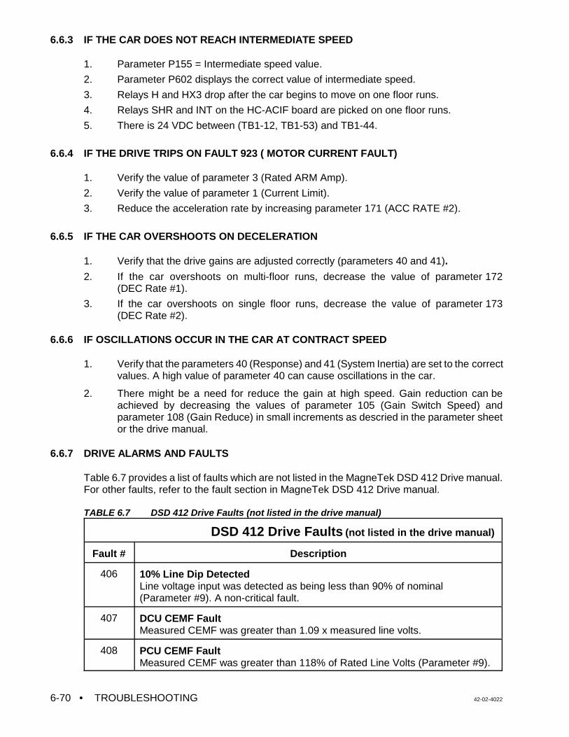
• TROUBLESHOOTING 42-02-40226-70
6.6.3 IF THE CAR DOES NOT REACH INTERMEDIATE SPEED
1. Parameter P155 = Intermediate speed value.
2. Parameter P602 displays the correct value of intermediate speed.
3. Relays H and HX3 drop after the car begins to move on one floor runs.
4. Relays SHR and INT on the HC-ACIF board are picked on one floor runs.
5. There is 24 VDC between (TB1-12, TB1-53) and TB1-44.
6.6.4 IF THE DRIVE TRIPS ON FAULT 923 ( MOTOR CURRENT FAULT)
1. Verify the value of parameter 3 (Rated ARM Amp).
2. Verify the value of parameter 1 (Current Limit).
3. Reduce the acceleration rate by increasing parameter 171 (ACC RATE #2).
6.6.5 IF THE CAR OVERSHOOTS ON DECELERATION
1. Verify that the drive gains are adjusted correctly (parameters 40 and 41).
2. If the car overshoots on multi-floor runs, decrease the value of parameter 172(DEC Rate #1).
3. If the car overshoots on single floor runs, decrease the value of parameter 173(DEC Rate #2).
6.6.6 IF OSCILLATIONS OCCUR IN THE CAR AT CONTRACT SPEED
1. Verify that the parameters 40 (Response) and 41 (System Inertia) are set to the correctvalues. A high value of parameter 40 can cause oscillations in the car.
2. There might be a need for reduce the gain at high speed. Gain reduction can beachieved by decreasing the values of parameter 105 (Gain Switch Speed) andparameter 108 (Gain Reduce) in small increments as descried in the parameter sheetor the drive manual.
6.6.7 DRIVE ALARMS AND FAULTS
Table 6.7 provides a list of faults which are not listed in the MagneTek DSD 412 Drive manual.For other faults, refer to the fault section in MagneTek DSD 412 Drive manual.
TABLE 6.7 DSD 412 Drive Faults (not listed in the drive manual)
DSD 412 Drive Faults (not listed in the drive manual)
Fault # Description
406 10% Line Dip Detected Line voltage input was detected as being less than 90% of nominal(Parameter #9). A non-critical fault.
407 DCU CEMF Fault Measured CEMF was greater than 1.09 x measured line volts.
408 PCU CEMF FaultMeasured CEMF was greater than 118% of Rated Line Volts (Parameter #9).
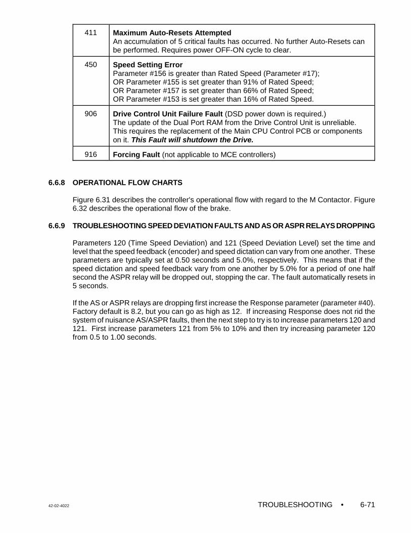
42-02-4022 TROUBLESHOOTING • 6-71
411 Maximum Auto-Resets Attempted An accumulation of 5 critical faults has occurred. No further Auto-Resets canbe performed. Requires power OFF-ON cycle to clear.
450 Speed Setting Error Parameter #156 is greater than Rated Speed (Parameter #17);OR Parameter #155 is set greater than 91% of Rated Speed;OR Parameter #157 is set greater than 66% of Rated Speed;OR Parameter #153 is set greater than 16% of Rated Speed.
906 Drive Control Unit Failure Fault (DSD power down is required.)The update of the Dual Port RAM from the Drive Control Unit is unreliable.This requires the replacement of the Main CPU Control PCB or componentson it. This Fault will shutdown the Drive.
916 Forcing Fault (not applicable to MCE controllers)
6.6.8 OPERATIONAL FLOW CHARTS
Figure 6.31 describes the controller's operational flow with regard to the M Contactor. Figure6.32 describes the operational flow of the brake.
6.6.9 TROUBLESHOOTING SPEED DEVIATION FAULTS AND AS OR ASPR RELAYS DROPPING
Parameters 120 (Time Speed Deviation) and 121 (Speed Deviation Level) set the time andlevel that the speed feedback (encoder) and speed dictation can vary from one another. Theseparameters are typically set at 0.50 seconds and 5.0%, respectively. This means that if thespeed dictation and speed feedback vary from one another by 5.0% for a period of one halfsecond the ASPR relay will be dropped out, stopping the car. The fault automatically resets in5 seconds.
If the AS or ASPR relays are dropping first increase the Response parameter (parameter #40).Factory default is 8.2, but you can go as high as 12. If increasing Response does not rid thesystem of nuisance AS/ASPR faults, then the next step to try is to increase parameters 120 and121. First increase parameters 121 from 5% to 10% and then try increasing parameter 120from 0.5 to 1.00 seconds.
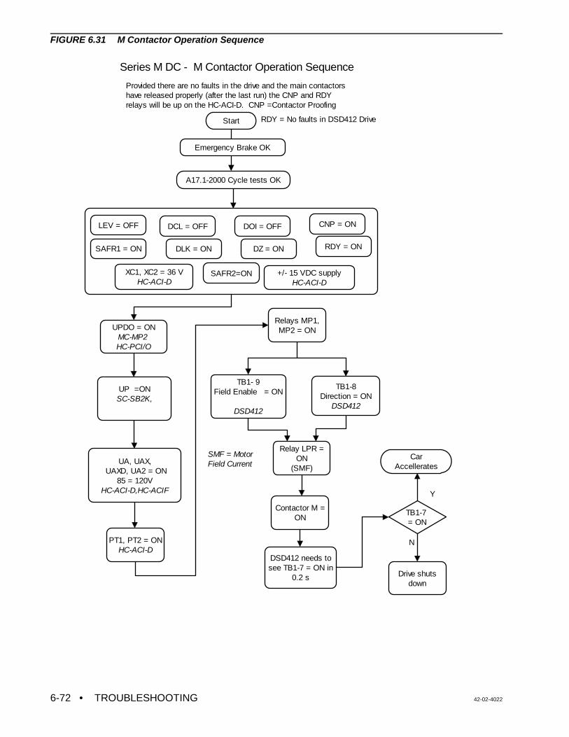
• TROUBLESHOOTING 42-02-40226-72
Series M DC - M Contactor Operation Sequence
Start
Provided there are no faults in the drive and the main contactors have released properly (after the last run) the CNP and RDY relays will be up on the HC-ACI-D. CNP =Contactor Proofing
RDY = No faults in DSD412 Drive
SAFR1 = ON
DOI = OFFDCL = OFFLEV = OFF
DLK = ON DZ = ON
CNP = ON
RDY = ON
UPDO = ONMC-MP2 HC-PCI/O
UP =ONSC-SB2K,
UA, UAX, UAXD, UA2 = ON
85 = 120VHC-ACI-D,HC-ACIF
PT1, PT2 = ONHC-ACI-D
Relays MP1, MP2 = ON
Relay LPR = ON
(SMF)
Contactor M = ON
TB1- 9Field Enable = ON
DSD412
TB1-8Direction = ON
DSD412
SMF = Motor Field Current
DSD412 needs to see TB1-7 = ON in
0.2 s
TB1-7 = ON
Y
N
Drive shuts down
Car Accellerates
XC1, XC2 = 36 VHC-ACI-D
+/- 15 VDC supplyHC-ACI-D
A17.1-2000 Cycle tests OK
Emergency Brake OK
SAFR2=ON
FIGURE 6.31 M Contactor Operation Sequence
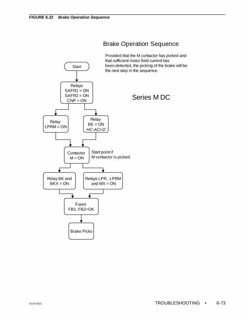
42-02-4022 TROUBLESHOOTING • 6-73
Brake Operation Sequence
Provided that the M contactor has picked andthat sufficient motor field current hasbeen detected, the picking of the brake will bethe next step in the sequence.
Start
Contactor M = ON
Relay LPRM = ON
Relay BK and BKX = ON
Relays LPR, LPRM and MX = ON
Fuses FB1, FB2=OK
RelaysSAFR1 = ONSAFR2 = ON
CNP = ON
Relay BE = ON
HC-ACI-D
Brake Picks
Series M DC
Start point if M contactor is picked.
FIGURE 6.32 Brake Operation Sequence
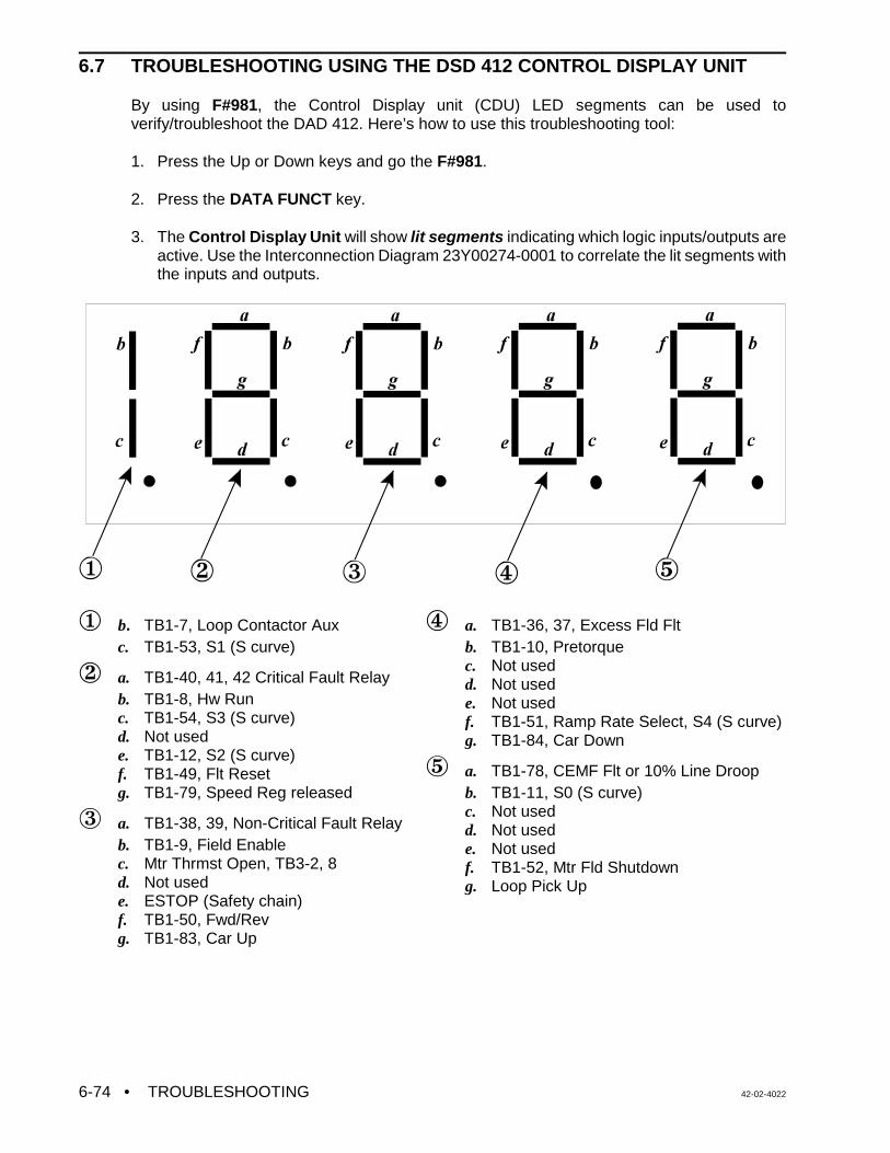
• TROUBLESHOOTING 42-02-40226-74
6.7 TROUBLESHOOTING USING THE DSD 412 CONTROL DISPLAY UNIT
By using F#981, the Control Display unit (CDU) LED segments can be used toverify/troubleshoot the DAD 412. Here’s how to use this troubleshooting tool:
1. Press the Up or Down keys and go the F#981.
2. Press the DATA FUNCT key.
3. The Control Display Unit will show lit segments indicating which logic inputs/outputs areactive. Use the Interconnection Diagram 23Y00274-0001 to correlate the lit segments withthe inputs and outputs.
Î b. TB1-7, Loop Contactor Auxc. TB1-53, S1 (S curve)
Ï a. TB1-40, 41, 42 Critical Fault Relayb. TB1-8, Hw Runc. TB1-54, S3 (S curve)d. Not usede. TB1-12, S2 (S curve)f. TB1-49, Flt Resetg. TB1-79, Speed Reg released
Ð a. TB1-38, 39, Non-Critical Fault Relayb. TB1-9, Field Enablec. Mtr Thrmst Open, TB3-2, 8d. Not usede. ESTOP (Safety chain)f. TB1-50, Fwd/Revg. TB1-83, Car Up
Ñ a. TB1-36, 37, Excess Fld Fltb. TB1-10, Pretorquec. Not usedd. Not usede. Not usedf. TB1-51, Ramp Rate Select, S4 (S curve)g. TB1-84, Car Down
Ò a. TB1-78, CEMF Flt or 10% Line Droopb. TB1-11, S0 (S curve)c. Not usedd. Not usede. Not usedf. TB1-52, Mtr Fld Shutdowng. Loop Pick Up
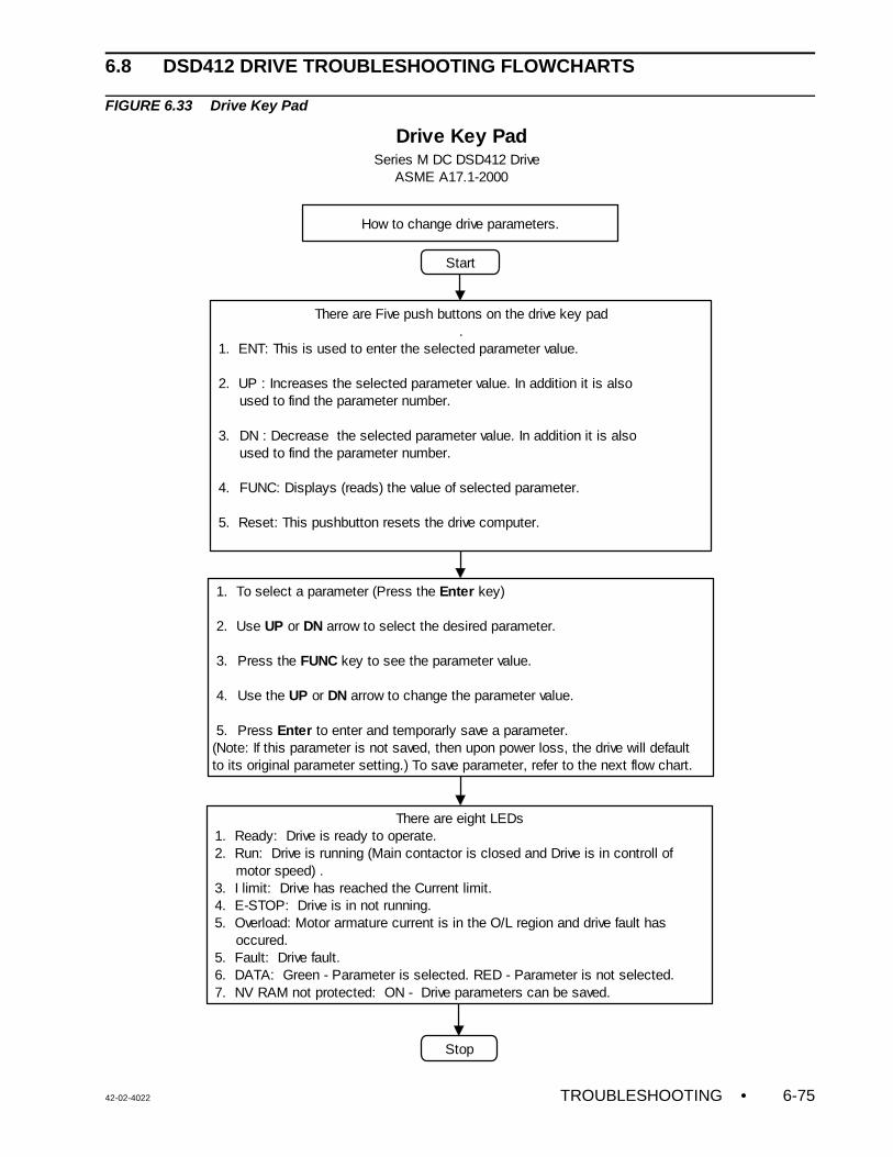
42-02-4022 TROUBLESHOOTING • 6-75
Start
There are Five push buttons on the drive key pad.
1. ENT: This is used to enter the selected parameter value.
2. UP : Increases the selected parameter value. In addition it is also used to find the parameter number.
3. DN : Decrease the selected parameter value. In addition it is also used to find the parameter number.
4. FUNC: Displays (reads) the value of selected parameter.
5. Reset: This pushbutton resets the drive computer.
1. To select a parameter (Press the Enter key) 2. Use UP or DN arrow to select the desired parameter.
3. Press the FUNC key to see the parameter value.
4. Use the UP or DN arrow to change the parameter value. 5. Press Enter to enter and temporarly save a parameter. (Note: If this parameter is not saved, then upon power loss, the drive will default to its original parameter setting.) To save parameter, refer to the next flow chart.
Stop
Drive Key PadSeries M DC DSD412 Drive ASME A17.1-2000
How to change drive parameters.
There are eight LEDs 1. Ready: Drive is ready to operate. 2. Run: Drive is running (Main contactor is closed and Drive is in controll of motor speed) . 3. I limit: Drive has reached the Current limit. 4. E-STOP: Drive is in not running. 5. Overload: Motor armature current is in the O/L region and drive fault has occured. 5. Fault: Drive fault. 6. DATA: Green - Parameter is selected. RED - Parameter is not selected. 7. NV RAM not protected: ON - Drive parameters can be saved.
6.8 DSD412 DRIVE TROUBLESHOOTING FLOWCHARTS
FIGURE 6.33 Drive Key Pad
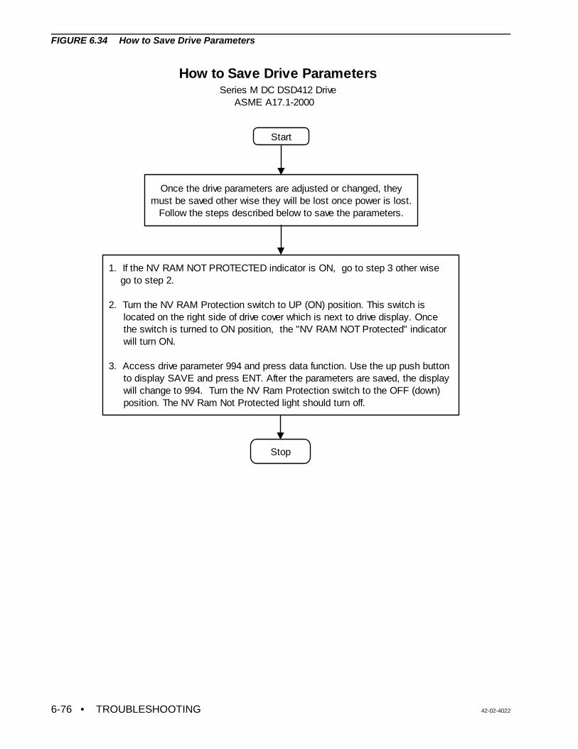
• TROUBLESHOOTING 42-02-40226-76
Start
Once the drive parameters are adjusted or changed, they must be saved other wise they will be lost once power is lost.
Follow the steps described below to save the parameters.
1. If the NV RAM NOT PROTECTED indicator is ON, go to step 3 other wise go to step 2.
2. Turn the NV RAM Protection switch to UP (ON) position. This switch is located on the right side of drive cover which is next to drive display. Once the switch is turned to ON position, the "NV RAM NOT Protected" indicator will turn ON. 3. Access drive parameter 994 and press data function. Use the up push button to display SAVE and press ENT. After the parameters are saved, the display will change to 994. Turn the NV Ram Protection switch to the OFF (down) position. The NV Ram Not Protected light should turn off.
Stop
How to Save Drive Parameters Series M DC DSD412 Drive ASME A17.1-2000
FIGURE 6.34 How to Save Drive Parameters
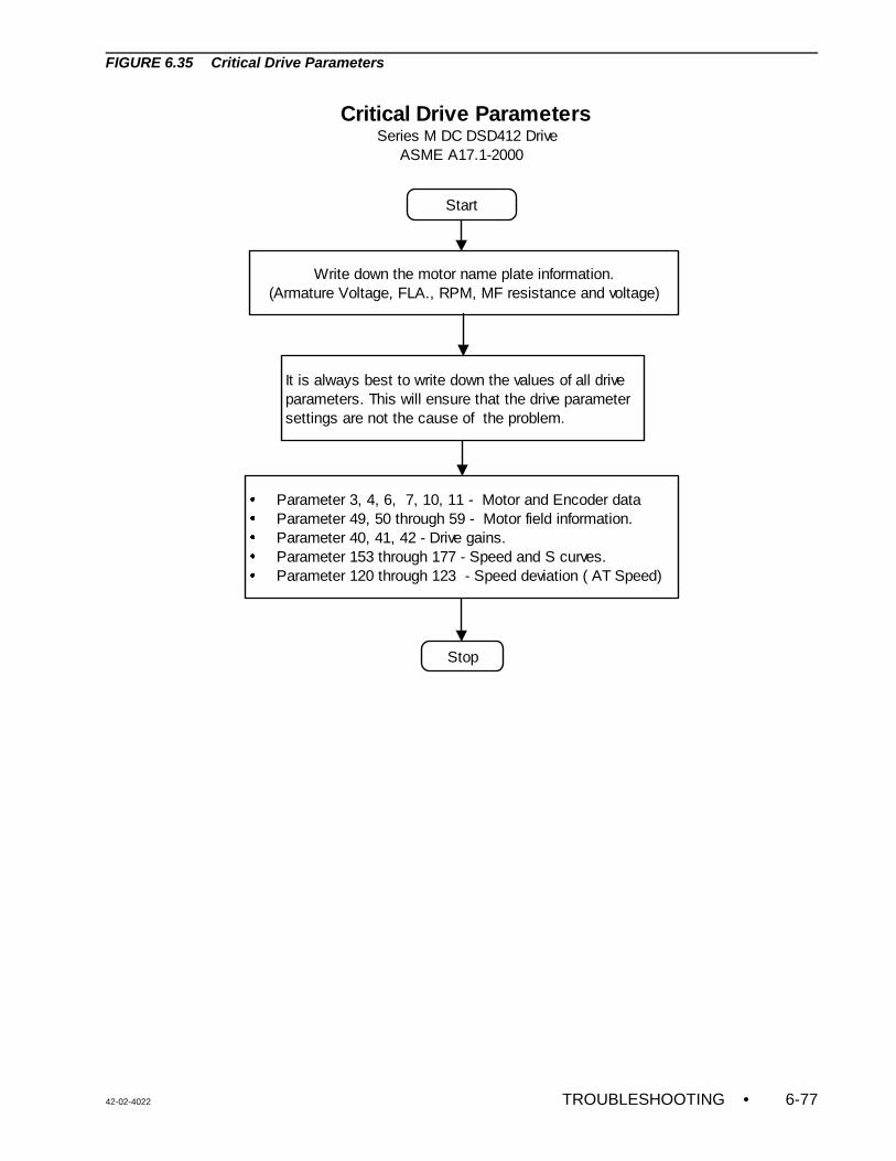
42-02-4022 TROUBLESHOOTING • 6-77
Start
Write down the motor name plate information.(Armature Voltage, FLA., RPM, MF resistance and voltage)
It is always best to write down the values of all drive parameters. This will ensure that the drive parameter settings are not the cause of the problem.
Parameter 3, 4, 6, 7, 10, 11 - Motor and Encoder data Parameter 49, 50 through 59 - Motor field information.Parameter 40, 41, 42 - Drive gains.Parameter 153 through 177 - Speed and S curves.Parameter 120 through 123 - Speed deviation ( AT Speed)
�
�
�
�
�
Stop
Critical Drive Parameters Series M DC DSD412 Drive ASME A17.1-2000
FIGURE 6.35 Critical Drive Parameters
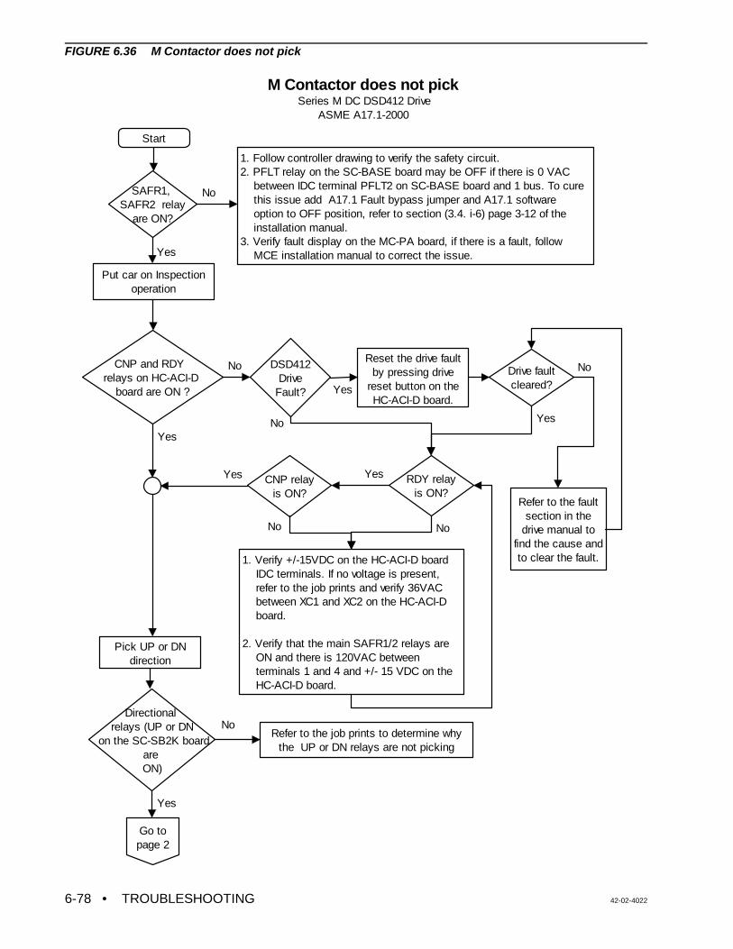
• TROUBLESHOOTING 42-02-40226-78
Start
Put car on Inspection operation
CNP and RDY relays on HC-ACI-D
board are ON ?
Reset the drive fault by pressing drive
reset button on the HC-ACI-D board.
CNP relayis ON?
Pick UP or DN direction
Directional relays (UP or DN
on the SC-SB2K board are ON)
Refer to the fault section in the
drive manual to find the cause and to clear the fault.
Yes
Refer to the job prints to determine why the UP or DN relays are not picking
No
M Contactor does not pick Series M DC DSD412 Drive ASME A17.1-2000
SAFR1, SAFR2 relay
are ON?
1. Follow controller drawing to verify the safety circuit.2. PFLT relay on the SC-BASE board may be OFF if there is 0 VAC between IDC terminal PFLT2 on SC-BASE board and 1 bus. To cure this issue add A17.1 Fault bypass jumper and A17.1 software option to OFF position, refer to section (3.4. i-6) page 3-12 of the installation manual.3. Verify fault display on the MC-PA board, if there is a fault, follow MCE installation manual to correct the issue.
No
Yes
DSD412Drive
Fault?
No
Yes
RDY relayis ON?
1. Verify +/-15VDC on the HC-ACI-D board IDC terminals. If no voltage is present, refer to the job prints and verify 36VAC between XC1 and XC2 on the HC-ACI-D board.
2. Verify that the main SAFR1/2 relays are ON and there is 120VAC between terminals 1 and 4 and +/- 15 VDC on the HC-ACI-D board.
Drive faultcleared?
No
No
No
Go to page 2
Yes
Yes
YesYes
No
FIGURE 6.36 M Contactor does not pick
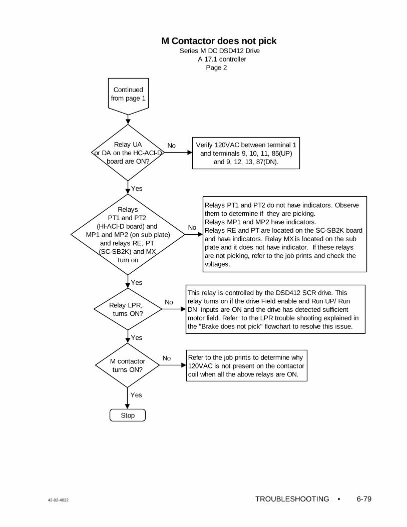
42-02-4022 TROUBLESHOOTING • 6-79
RelaysPT1 and PT2
(HI-ACI-D board) and MP1 and MP2 (on sub plate)
and relays RE, PT (SC-SB2K) and MX
turn on
M contactorturns ON?
Verify 120VAC between terminal 1 and terminals 9, 10, 11, 85(UP)
and 9, 12, 13, 87(DN).
Relay UAor DA on the HC-ACI-D
board are ON?
Refer to the job prints to determine why 120VAC is not present on the contactor coil when all the above relays are ON.
No
Yes
Stop
No
Yes
Relays PT1 and PT2 do not have indicators. Observe them to determine if they are picking.Relays MP1 and MP2 have indicators.Relays RE and PT are located on the SC-SB2K board and have indicators. Relay MX is located on the sub plate and it does not have indicator. If these relays are not picking, refer to the job prints and check the voltages.
No
Continued from page 1
M Contactor does not pick Series M DC DSD412 Drive A 17.1 controller Page 2
Relay LPR, turns ON?
This relay is controlled by the DSD412 SCR drive. This relay turns on if the drive Field enable and Run UP/ Run DN inputs are ON and the drive has detected sufficient motor field. Refer to the LPR trouble shooting explained in the "Brake does not pick" flowchart to resolve this issue.
Yes
No
Yes
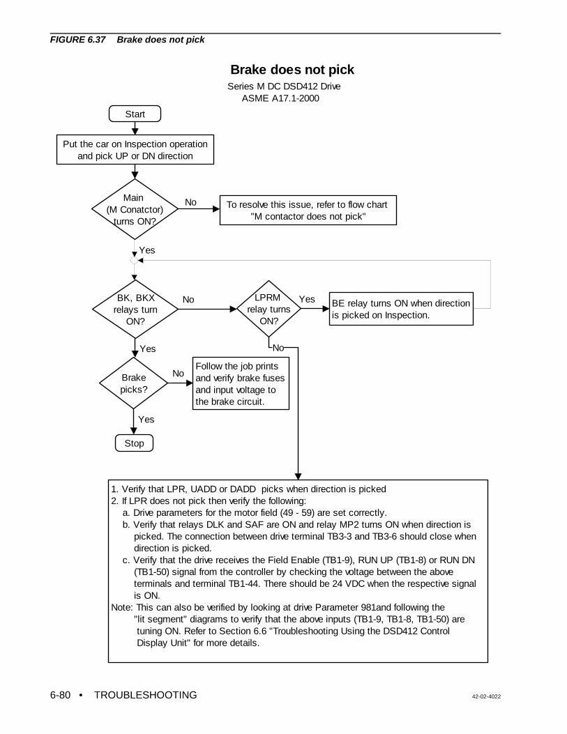
• TROUBLESHOOTING 42-02-40226-80
Start
Put the car on Inspection operation and pick UP or DN direction
Main (M Conatctor)
turns ON?
To resolve this issue, refer to flow chart "M contactor does not pick"
BK, BKXrelays turn
ON?
No
LPRM relay turns
ON?
No BE relay turns ON when direction is picked on Inspection.
1. Verify that LPR, UADD or DADD picks when direction is picked 2. If LPR does not pick then verify the following: a. Drive parameters for the motor field (49 - 59) are set correctly. b. Verify that relays DLK and SAF are ON and relay MP2 turns ON when direction is picked. The connection between drive terminal TB3-3 and TB3-6 should close when direction is picked. c. Verify that the drive receives the Field Enable (TB1-9), RUN UP (TB1-8) or RUN DN (TB1-50) signal from the controller by checking the voltage between the above terminals and terminal TB1-44. There should be 24 VDC when the respective signal is ON. Note: This can also be verified by looking at drive Parameter 981and following the "lit segment" diagrams to verify that the above inputs (TB1-9, TB1-8, TB1-50) are tuning ON. Refer to Section 6.6 "Troubleshooting Using the DSD412 Control Display Unit" for more details.
No
Yes
Stop
Brake does not pickSeries M DC DSD412 Drive ASME A17.1-2000
Brakepicks?
Yes
Follow the job prints and verify brake fuses and input voltage to the brake circuit.
Yes
No
Yes
FIGURE 6.37 Brake does not pick
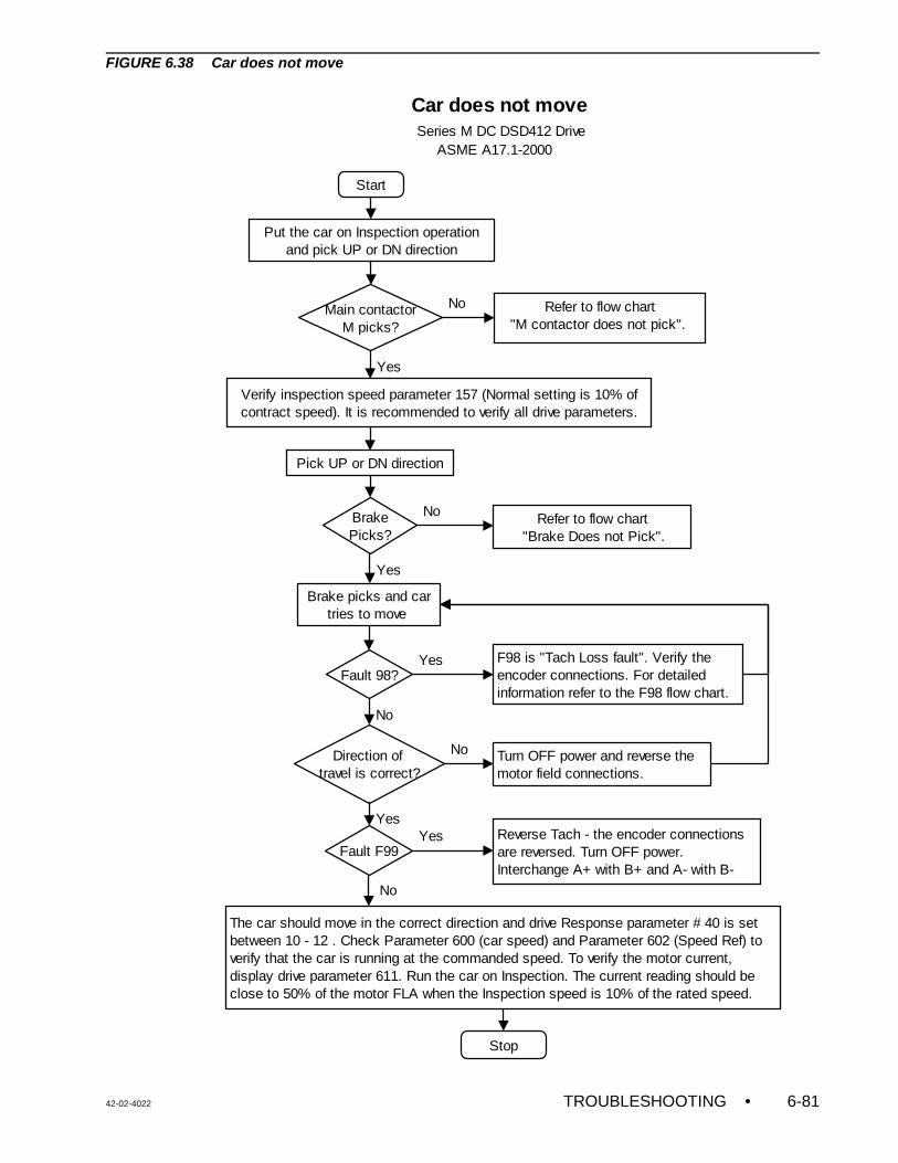
42-02-4022 TROUBLESHOOTING • 6-81
Start
Put the car on Inspection operation and pick UP or DN direction
Main contactorM picks?
Refer to flow chart "M contactor does not pick".
No
Verify inspection speed parameter 157 (Normal setting is 10% of contract speed). It is recommended to verify all drive parameters.
Yes
BrakePicks?
Refer to flow chart"Brake Does not Pick".
No
Brake picks and car tries to move
Fault 98?
Yes
F98 is "Tach Loss fault". Verify the encoder connections. For detailed information refer to the F98 flow chart.
Direction of travel is correct?
No
Yes
Turn OFF power and reverse the motor field connections.
No
The car should move in the correct direction and drive Response parameter # 40 is set between 10 - 12 . Check Parameter 600 (car speed) and Parameter 602 (Speed Ref) to verify that the car is running at the commanded speed. To verify the motor current, display drive parameter 611. Run the car on Inspection. The current reading should be close to 50% of the motor FLA when the Inspection speed is 10% of the rated speed.
Stop
Car does not move Series M DC DSD412 Drive ASME A17.1-2000
Pick UP or DN direction
Fault F99
YesReverse Tach - the encoder connections are reversed. Turn OFF power. Interchange A+ with B+ and A- with B-
No
Yes
FIGURE 6.38 Car does not move
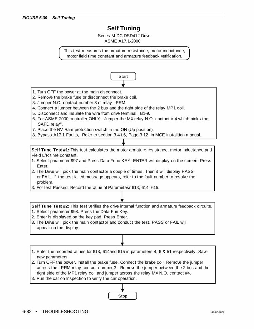
• TROUBLESHOOTING 42-02-40226-82
Self Tuning
Start
1. Turn OFF the power at the main disconnect.2. Remove the brake fuse or disconnect the brake coil.3. Jumper N.O. contact number 3 of relay LPRM.4. Connect a jumper between the 2 bus and the right side of the relay MP1 coil.5. Disconnect and insulate the wire from drive terminal TB1-9.6. For ASME 2000 controller ONLY: Jumper the MX relay N.O. contact # 4 which picks the SAFD relay".7. Place the NV Ram protection switch in the ON (Up position).8. Bypass A17.1 Faults, Refer to section 3.4-i.6, Page 3-12 in MCE installtion manual.
Self Tune Test #1: This test calculates the motor armature resistance, motor inductance andField L/R time constant.1. Select parameter 997 and Press Data Func KEY. ENTER will display on the screen. Press Enter.2. The Drive will pick the main contactor a couple of times. Then it will display PASS or FAIL. If the test failed message appears, refer to the fault number to resolve the problem.3. For test Passed: Record the value of Parametesr 613, 614, 615.
Self Tune Test #2: This test verifies the drive internal function and armature feedback circuits.1. Select parameter 998. Press the Data Fun Key.2. Enter is displayed on the key pad. Press Enter.3. The Drive will pick the main contactor and conduct the test. PASS or FAIL will appear on the display.
1. Enter the recorded values for 613, 614and 615 in parameters 4, 6 & 51 respectively. Save new parameters.2. Turn OFF the power. Install the brake fuse. Connect the brake coil. Remove the jumper across the LPRM relay contact number 3. Remove the jumper between the 2 bus and the right side of the MP1 relay coil and jumper across the relay MX N.O. contact #4.3. Run the car on Inspection to verify the car operation.
Stop
Series M DC DSD412 Drive ASME A17.1-2000
This test measures the armature resistance, motor inductance, motor field time constant and armature feedback verification.
FIGURE 6.39 Self Tuning
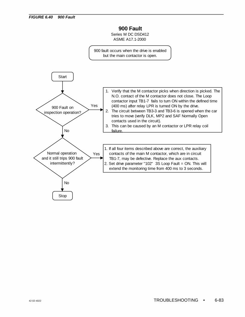
42-02-4022 TROUBLESHOOTING • 6-83
Start
900 Fault oninspection operation?
1. Verify that the M contactor picks when direction is picked. The N.O. contact of the M contactor does not close. The Loop contactor input TB1-7 fails to turn ON within the defined time (400 ms) after relay LPR is turned ON by the drive. 2. The circuit between TB3-3 and TB3-6 is opened when the car tries to move (verify DLK, MP2 and SAF Normally Open contacts used in the circuit). 3. This can be caused by an M contactor or LPR relay coil failure.
Normal operation and it still trips 900 fault
intermittently?
Stop
No
1. If all four items described above are correct, the auxiliary contacts of the main M contactor, which are in circuit TB1-7, may be defective. Replace the aux contacts.2. Set drive parameter "102" 3S Loop Fault = ON. This will extend the monitoring time from 400 ms to 3 seconds.
Yes
No
Yes
900 FaultSeries M DC DSD412 ASME A17.1-2000
900 fault occurs when the drive is enabled but the main contactor is open.
FIGURE 6.40 900 Fault
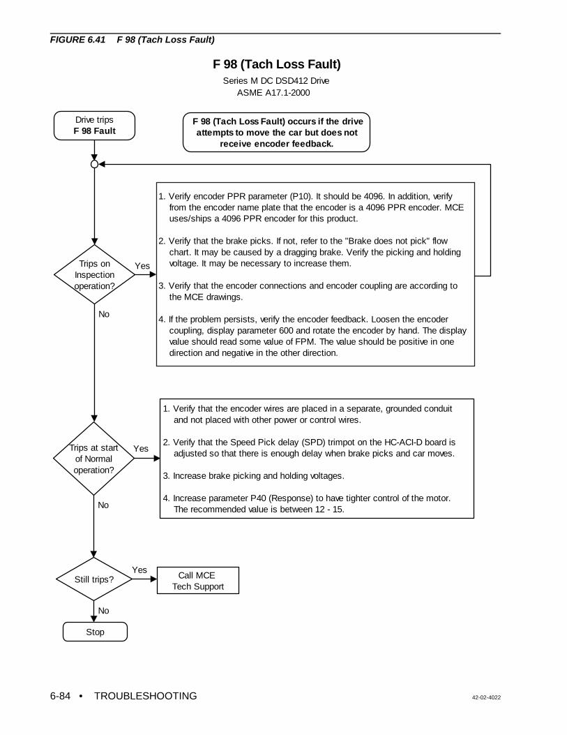
• TROUBLESHOOTING 42-02-40226-84
Drive tripsF 98 Fault
Trips onInspection operation?
Trips at startof Normal operation?
Still trips?
1. Verify that the encoder wires are placed in a separate, grounded conduit and not placed with other power or control wires.
2. Verify that the Speed Pick delay (SPD) trimpot on the HC-ACI-D board is adjusted so that there is enough delay when brake picks and car moves.
3. Increase brake picking and holding voltages.
4. Increase parameter P40 (Response) to have tighter control of the motor. The recommended value is between 12 - 15.
Call MCE Tech Support
Stop
Yes
No
Yes
1. Verify encoder PPR parameter (P10). It should be 4096. In addition, verify from the encoder name plate that the encoder is a 4096 PPR encoder. MCE uses/ships a 4096 PPR encoder for this product. 2. Verify that the brake picks. If not, refer to the "Brake does not pick" flow chart. It may be caused by a dragging brake. Verify the picking and holding voltage. It may be necessary to increase them.
3. Verify that the encoder connections and encoder coupling are according to the MCE drawings.
4. If the problem persists, verify the encoder feedback. Loosen the encoder coupling, display parameter 600 and rotate the encoder by hand. The display value should read some value of FPM. The value should be positive in one direction and negative in the other direction.
Yes
F 98 (Tach Loss Fault) Series M DC DSD412 Drive ASME A17.1-2000
F 98 (Tach Loss Fault) occurs if the drive attempts to move the car but does not
receive encoder feedback.
No
No
FIGURE 6.41 F 98 (Tach Loss Fault)
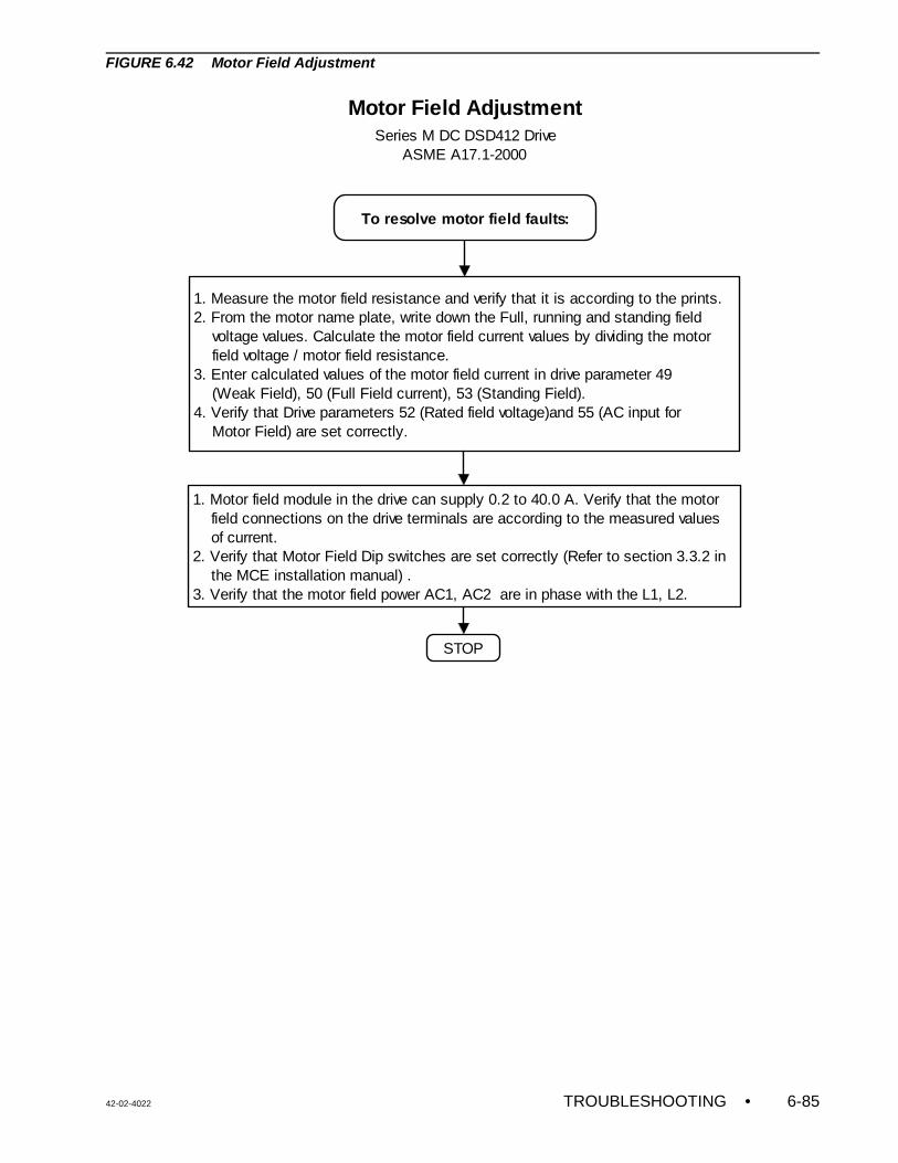
42-02-4022 TROUBLESHOOTING • 6-85
Motor Field Adjustment
To resolve motor field faults:
1. Measure the motor field resistance and verify that it is according to the prints.2. From the motor name plate, write down the Full, running and standing field voltage values. Calculate the motor field current values by dividing the motor field voltage / motor field resistance.3. Enter calculated values of the motor field current in drive parameter 49 (Weak Field), 50 (Full Field current), 53 (Standing Field).4. Verify that Drive parameters 52 (Rated field voltage)and 55 (AC input for Motor Field) are set correctly.
1. Motor field module in the drive can supply 0.2 to 40.0 A. Verify that the motor field connections on the drive terminals are according to the measured values of current.2. Verify that Motor Field Dip switches are set correctly (Refer to section 3.3.2 in the MCE installation manual) .3. Verify that the motor field power AC1, AC2 are in phase with the L1, L2.
STOP
Series M DC DSD412 Drive ASME A17.1-2000
FIGURE 6.42 Motor Field Adjustment
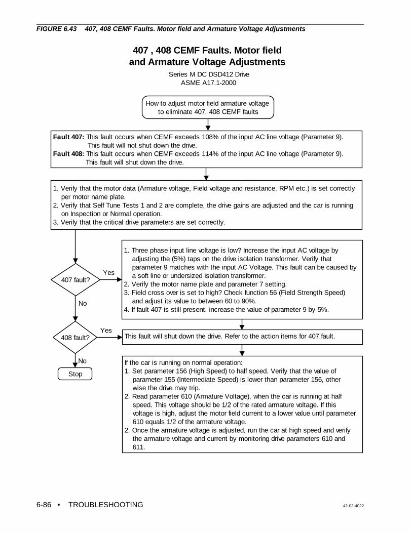
• TROUBLESHOOTING 42-02-40226-86
407 , 408 CEMF Faults. Motor field and Armature Voltage Adjustments
How to adjust motor field armature voltage to eliminate 407, 408 CEMF faults
1. Verify that the motor data (Armature voltage, Field voltage and resistance, RPM etc.) is set correctly per motor name plate.2. Verify that Self Tune Tests 1 and 2 are complete, the drive gains are adjusted and the car is running on Inspection or Normal operation.3. Verify that the critical drive parameters are set correctly.
If the car is running on normal operation:1. Set parameter 156 (High Speed) to half speed. Verify that the value of parameter 155 (Intermediate Speed) is lower than parameter 156, other wise the drive may trip.2. Read parameter 610 (Armature Voltage), when the car is running at half speed. This voltage should be 1/2 of the rated armature voltage. If this voltage is high, adjust the motor field current to a lower value until parameter 610 equals 1/2 of the armature voltage. 2. Once the armature voltage is adjusted, run the car at high speed and verify the armature voltage and current by monitoring drive parameters 610 and 611.
Fault 407: This fault occurs when CEMF exceeds 108% of the input AC line voltage (Parameter 9). This fault will not shut down the drive.Fault 408: This fault occurs when CEMF exceeds 114% of the input AC line voltage (Parameter 9). This fault will shut down the drive.
407 fault?
1. Three phase input line voltage is low? Increase the input AC voltage by adjusting the (5%) taps on the drive isolation transformer. Verify that parameter 9 matches with the input AC Voltage. This fault can be caused by a soft line or undersized isolation transformer. 2. Verify the motor name plate and parameter 7 setting. 3. Field cross over is set to high? Check function 56 (Field Strength Speed) and adjust its value to between 60 to 90%.4. If fault 407 is still present, increase the value of parameter 9 by 5%.
408 fault? This fault will shut down the drive. Refer to the action items for 407 fault.
Yes
No
Stop
No
Yes
Series M DC DSD412 Drive ASME A17.1-2000
FIGURE 6.43 407, 408 CEMF Faults. Motor field and Armature Voltage Adjustments
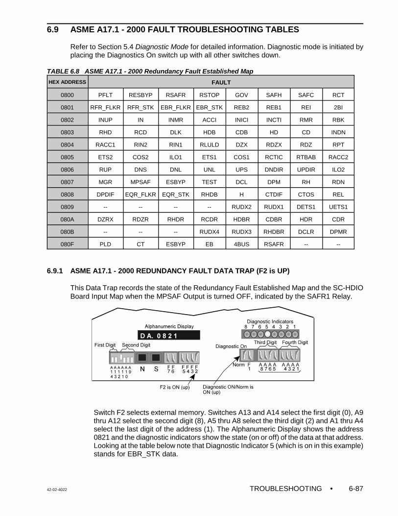
42-02-4022 TROUBLESHOOTING • 6-87
6.9 ASME A17.1 - 2000 FAULT TROUBLESHOOTING TABLES
Refer to Section 5.4 Diagnostic Mode for detailed information. Diagnostic mode is initiated byplacing the Diagnostics On switch up with all other switches down.
TABLE 6.8 ASME A17.1 - 2000 Redundancy Fault Established Map
HEX ADDRESS FAULT
0800 PFLT RESBYP RSAFR RSTOP GOV SAFH SAFC RCT
0801 RFR_FLKR RFR_STK EBR_FLKR EBR_STK REB2 REB1 REI 2BI
0802 INUP IN INMR ACCI INICI INCTI RMR RBK
0803 RHD RCD DLK HDB CDB HD CD INDN
0804 RACC1 RIN2 RIN1 RLULD DZX RDZX RDZ RPT
0805 ETS2 COS2 ILO1 ETS1 COS1 RCTIC RTBAB RACC2
0806 RUP DNS DNL UNL UPS DNDIR UPDIR ILO2
0807 MGR MPSAF ESBYP TEST DCL DPM RH RDN
0808 DPDIF EQR_FLKR EQR_STK RHDB H CTDIF CTOS REL
0809 -- -- -- -- RUDX2 RUDX1 DETS1 UETS1
080A DZRX RDZR RHDR RCDR HDBR CDBR HDR CDR
080B -- -- -- RUDX4 RUDX3 RHDBR DCLR DPMR
080F PLD CT ESBYP EB 4BUS RSAFR -- --
6.9.1 ASME A17.1 - 2000 REDUNDANCY FAULT DATA TRAP (F2 is UP)
This Data Trap records the state of the Redundancy Fault Established Map and the SC-HDIOBoard Input Map when the MPSAF Output is turned OFF, indicated by the SAFR1 Relay.
Switch F2 selects external memory. Switches A13 and A14 select the first digit (0), A9thru A12 select the second digit (8), A5 thru A8 select the third digit (2) and A1 thru A4select the last digit of the address (1). The Alphanumeric Display shows the address0821 and the diagnostic indicators show the state (on or off) of the data at that address.Looking at the table below note that Diagnostic Indicator 5 (which is on in this example)stands for EBR_STK data.
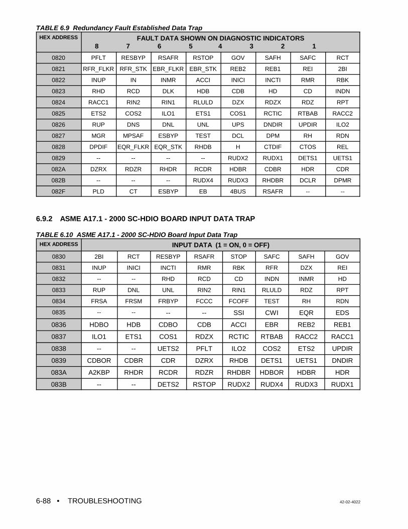
• TROUBLESHOOTING 42-02-40226-88
TABLE 6.9 Redundancy Fault Established Data TrapHEX ADDRESS FAULT DATA SHOWN ON DIAGNOSTIC INDICATORS
8 7 6 5 4 3 2 1
0820 PFLT RESBYP RSAFR RSTOP GOV SAFH SAFC RCT
0821 RFR_FLKR RFR_STK EBR_FLKR EBR_STK REB2 REB1 REI 2BI
0822 INUP IN INMR ACCI INICI INCTI RMR RBK
0823 RHD RCD DLK HDB CDB HD CD INDN
0824 RACC1 RIN2 RIN1 RLULD DZX RDZX RDZ RPT
0825 ETS2 COS2 ILO1 ETS1 COS1 RCTIC RTBAB RACC2
0826 RUP DNS DNL UNL UPS DNDIR UPDIR ILO2
0827 MGR MPSAF ESBYP TEST DCL DPM RH RDN
0828 DPDIF EQR_FLKR EQR_STK RHDB H CTDIF CTOS REL
0829 -- -- -- -- RUDX2 RUDX1 DETS1 UETS1
082A DZRX RDZR RHDR RCDR HDBR CDBR HDR CDR
082B -- -- -- RUDX4 RUDX3 RHDBR DCLR DPMR
082F PLD CT ESBYP EB 4BUS RSAFR -- --
6.9.2 ASME A17.1 - 2000 SC-HDIO BOARD INPUT DATA TRAP
TABLE 6.10 ASME A17.1 - 2000 SC-HDIO Board Input Data TrapHEX ADDRESS INPUT DATA (1 = ON, 0 = OFF)
0830 2BI RCT RESBYP RSAFR STOP SAFC SAFH GOV
0831 INUP INICI INCTI RMR RBK RFR DZX REI
0832 -- -- RHD RCD CD INDN INMR HD
0833 RUP DNL UNL RIN2 RIN1 RLULD RDZ RPT
0834 FRSA FRSM FRBYP FCCC FCOFF TEST RH RDN
0835 -- -- -- -- SSI CWI EQR EDS
0836 HDBO HDB CDBO CDB ACCI EBR REB2 REB1
0837 ILO1 ETS1 COS1 RDZX RCTIC RTBAB RACC2 RACC1
0838 -- -- UETS2 PFLT ILO2 COS2 ETS2 UPDIR
0839 CDBOR CDBR CDR DZRX RHDB DETS1 UETS1 DNDIR
083A A2KBP RHDR RCDR RDZR RHDBR HDBOR HDBR HDR
083B -- -- DETS2 RSTOP RUDX2 RUDX4 RUDX3 RUDX1
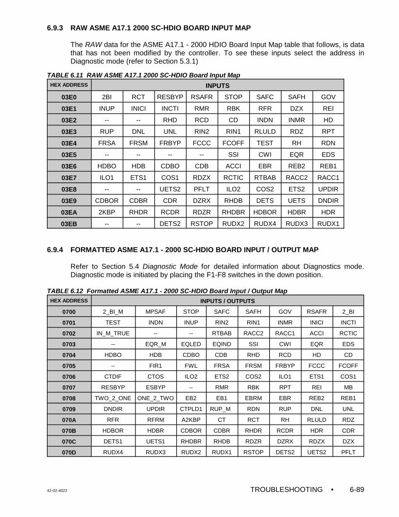
42-02-4022 TROUBLESHOOTING • 6-89
6.9.3 RAW ASME A17.1 2000 SC-HDIO BOARD INPUT MAP
The RAW data for the ASME A17.1 - 2000 HDIO Board Input Map table that follows, is datathat has not been modified by the controller. To see these inputs select the address inDiagnostic mode (refer to Section 5.3.1)
TABLE 6.11 RAW ASME A17.1 2000 SC-HDIO Board Input MapHEX ADDRESS INPUTS
03E0 2BI RCT RESBYP RSAFR STOP SAFC SAFH GOV
03E1 INUP INICI INCTI RMR RBK RFR DZX REI
03E2 -- -- RHD RCD CD INDN INMR HD
03E3 RUP DNL UNL RIN2 RIN1 RLULD RDZ RPT
03E4 FRSA FRSM FRBYP FCCC FCOFF TEST RH RDN
03E5 -- -- -- -- SSI CWI EQR EDS
03E6 HDBO HDB CDBO CDB ACCI EBR REB2 REB1
03E7 ILO1 ETS1 COS1 RDZX RCTIC RTBAB RACC2 RACC1
03E8 -- -- UETS2 PFLT ILO2 COS2 ETS2 UPDIR
03E9 CDBOR CDBR CDR DZRX RHDB DETS UETS DNDIR
03EA 2KBP RHDR RCDR RDZR RHDBR HDBOR HDBR HDR
03EB -- -- DETS2 RSTOP RUDX2 RUDX4 RUDX3 RUDX1
6.9.4 FORMATTED ASME A17.1 - 2000 SC-HDIO BOARD INPUT / OUTPUT MAP
Refer to Section 5.4 Diagnostic Mode for detailed information about Diagnostics mode.Diagnostic mode is initiated by placing the F1-F8 switches in the down position.
TABLE 6.12 Formatted ASME A17.1 - 2000 SC-HDIO Board Input / Output MapHEX ADDRESS INPUTS / OUTPUTS
0700 2_BI_M MPSAF STOP SAFC SAFH GOV RSAFR 2_BI
0701 TEST INDN INUP RIN2 RIN1 INMR INICI INCTI
0702 IN_M_TRUE -- -- RTBAB RACC2 RACC1 ACCI RCTIC
0703 -- EQR_M EQLED EQIND SSI CWI EQR EDS
0704 HDBO HDB CDBO CDB RHD RCD HD CD
0705 -- FIR1 FWL FRSA FRSM FRBYP FCCC FCOFF
0706 CTDIF CTOS ILO2 ETS2 COS2 ILO1 ETS1 COS1
0707 RESBYP ESBYP – RMR RBK RPT REI MB
0708 TWO_2_ONE ONE_2_TWO EB2 EB1 EBRM EBR REB2 REB1
0709 DNDIR UPDIR CTPLD1 RUP_M RDN RUP DNL UNL
070A RFR RFRM A2KBP CT RCT RH RLULD RDZ
070B HDBOR HDBR CDBOR CDBR RHDR RCDR HDR CDR
070C DETS1 UETS1 RHDBR RHDB RDZR DZRX RDZX DZX
070D RUDX4 RUDX3 RUDX2 RUDX1 RSTOP DETS2 UETS2 PFLT
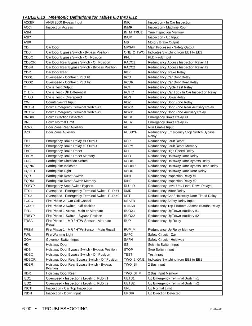
• TROUBLESHOOTING 42-02-40226-90
TABLE 6.13 Mnemonic Definitions for Tables 6.8 thru 6.12A2KBP ANSI 2000 Bypass Input INICI Inspection - In Car Inspection
ACCI Inspection Access INMR Inspection - Machine Room
ASI4 IN_M_TRUE True Inspection Memory
ASI7 INUP Inspection - Up Input
ASI8 MB Motor / Brake Output
CD Car Door MPSAF Main Processor - Safety Output
CDB Car Door Bypass Switch - Bypass Position ONE_2_TWO Indicates Switching from EB1 to EB2
CDBO Car Door Bypass Switch - Off Position PFLT PLD Fault Input
CDBOR Car Door Rear Bypass Switch - Off Position RACC1 Redundancy Access Inspection Relay #1
CDBR Car Door Rear Bypass Switch - Bypass Position RACC2 Redundancy Access Inspection Relay #2
CDR Car Door Rear RBK Redundancy Brake Relay
COS1 Overspeed - Contract, PLD #1 RCD Redundancy Car Door Relay
COS2 Overspeed - Contract, PLD #2 RCDR Redundancy Car Door Rear Relay
CT Cycle Test Output RCT Redundancy Cycle Test Relay
CTDIF Cycle Test - DP Differential RCTIC Redundancy Car Top / In Car Inspection Relay
CTOS Cycle Test - Overspeed RDN Redundancy Down Relay
CWI Counterweight Input RDZ Redundancy Door Zone Relay
DETS1 Down Emergency Terminal Switch #1 RDZR Redundancy Door Zone Rear Auxiliary Relay
DETS2 Down Emergency Terminal Switch #2 RDZX Redundancy Door Zone Auxiliary Relay
DNDIR Down Direction Detected REB1 Emergency Brake Relay #1
DNL Down Normal Limit REB2 Emergency Brake Relay #2
DZRX Door Zone Rear Auxiliary REI Run Enable Input
DZX Door Zone Auxiliary RESBYP Redundancy Emergency Stop Switch BypassRelay
EB1 Emergency Brake Relay #1 Output RFR Redundancy Fault Reset
EB2 Emergency Brake Relay #2 Output RFRM Redundancy Fault Reset Memory
EBR Emergency Brake Reset RH Redundancy High Speed Relay
EBRM Emergency Brake Reset Memory RHD Redundancy Hoistway Door Relay
EDS Earthquake Direction Switch RHDB Redundancy Hoistway Door Bypass Relay
EQIND Earthquake Indicator RHDBR Redundancy Hoistway Door Bypass Rear Relay
EQLED Earthquake Light RHDR Redundancy Hoistway Door Rear Relay
EQR Earthquake Reset Switch RIN1 Redundancy Inspection Relay #1
EQRM Earthquake Reset Switch Memory RIN2 Redundancy Inspection Relay #2
ESBYP Emergency Stop Switch Bypass RLULD Redundancy Level Up / Level Down Relays
ETS1 Overspeed - Emergency Terminal Switch, PLD #1 RMR Redundancy Motor Relay
ETS2 Overspeed - Emergency Terminal Switch, PLD #2 RPT Redundancy Car / Hoistway Door Timed Relay
FCCC Fire Phase 2 - Car Call Cancel RSAFR Redundancy Safety Relay Input
FCOFF Fire Phase 2 Switch - Off position RTBAB Redundancy Top / Bottom Access Buttons Relay
FIR1 Fire Phase 1 Active - Main or Alternate RUDX1 Redundancy Up/Down Auxiliary #1
FRBYP Fire Phase 1 Switch - Bypass Position RUDX2 Redundancy Up/Down Auxiliary #2
FRSA Fire Phase 1 - MR / HTW Sensor - AlternateRecall
RUP Redundancy Up Relay
FRSM Fire Phase 1 - MR / HTW Sensor - Main Recall RUP_M Redundancy Up Relay Memory
FWL Fire Warning Light SAFC Safety Circuit - Car
GOV Governor Switch Input SAFH Safety Circuit - Hoistway
HD Hoistway Door SSI Seismic Switch Input
HDB Hoistway Door Bypass Switch - Bypass Position STOP Stop Switch Input
HDBO Hoistway Door Bypass Switch - Off Position TEST Test Input
HDBOR Hoistway Door Rear Bypass Switch - Off Position TWO_2_ONE Indicates Switching from EB2 to EB1
HDBR Hoistway Door Rear Bypass Switch - BypassPosition
TWO_BI 2 Bus Input
HDR Hoistway Door Rear TWO_BI_M 2 Bus Input Memory
ILO1 Overspeed - Inspection / Leveling, PLD #1 UETS1 Up Emergency Terminal Switch #1
ILO2 Overspeed - Inspection / Leveling, PLD #2 UETS2 Up Emergency Terminal Switch #2
INCTI Inspection - Car Top Inspection UNL Up Normal Limit
INDN Inspection - Down Input UPDIR Up Direction Detected
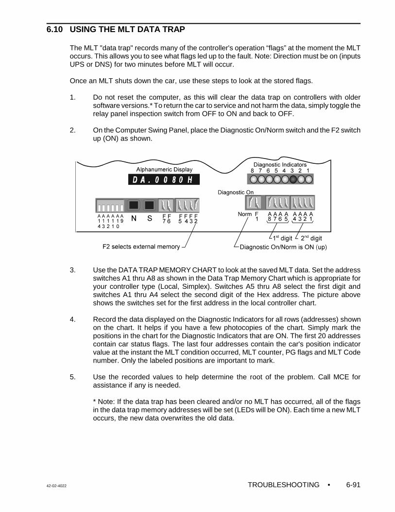
42-02-4022 TROUBLESHOOTING • 6-91
6.10 USING THE MLT DATA TRAP
The MLT "data trap" records many of the controller's operation “flags” at the moment the MLToccurs. This allows you to see what flags led up to the fault. Note: Direction must be on (inputsUPS or DNS) for two minutes before MLT will occur.
Once an MLT shuts down the car, use these steps to look at the stored flags.
1. Do not reset the computer, as this will clear the data trap on controllers with oldersoftware versions.* To return the car to service and not harm the data, simply toggle therelay panel inspection switch from OFF to ON and back to OFF.
2. On the Computer Swing Panel, place the Diagnostic On/Norm switch and the F2 switchup (ON) as shown.
3. Use the DATA TRAP MEMORY CHART to look at the saved MLT data. Set the addressswitches A1 thru A8 as shown in the Data Trap Memory Chart which is appropriate foryour controller type (Local, Simplex). Switches A5 thru A8 select the first digit andswitches A1 thru A4 select the second digit of the Hex address. The picture aboveshows the switches set for the first address in the local controller chart.
4. Record the data displayed on the Diagnostic Indicators for all rows (addresses) shownon the chart. It helps if you have a few photocopies of the chart. Simply mark thepositions in the chart for the Diagnostic Indicators that are ON. The first 20 addressescontain car status flags. The last four addresses contain the car's position indicatorvalue at the instant the MLT condition occurred, MLT counter, PG flags and MLT Codenumber. Only the labeled positions are important to mark.
5. Use the recorded values to help determine the root of the problem. Call MCE forassistance if any is needed.
* Note: If the data trap has been cleared and/or no MLT has occurred, all of the flagsin the data trap memory addresses will be set (LEDs will be ON). Each time a new MLToccurs, the new data overwrites the old data.
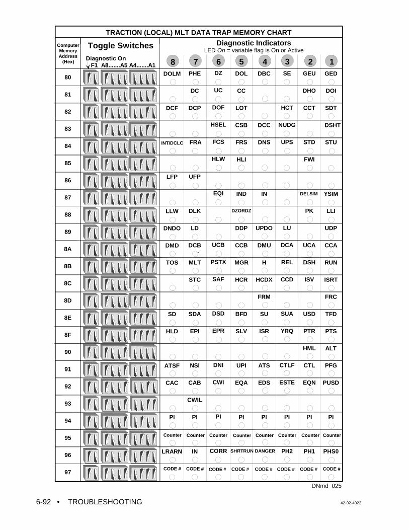
• TROUBLESHOOTING 42-02-40226-92
GED
DOI
SDT
DSHT
STU
YSIM
LLI
UDP
CCA
RUN
ISRT
FRC
TFD
PTS
ALT
PFG
PUSD
PI
PHS0
GEU
DHO
CCT
STD
FWI
PK
UCA
DSH
ISV
USD
PTR
HML
CTL
EQN
PI
PH1
SE
HCT
NUDG
UPS
LU
DCA
REL
CCD
SUA
YRQ
CTLF
ESTE
PI
PH2
DBC
DCC
DNS
IN
UPDO
DMU
H
HCDX
FRM
SU
ISR
ATS
EDS
PI
DOL
CC
LOT
CSB
FRS
HLI
IND
DDP
CCB
MGR
HCR
BFD
SLV
UPI
EQA
PI
DZ
UC
DOF
HSEL
FCS
HLW
EQI
UCB
PSTX
SAF
DSD
EPR
DNI
CWI
PI
CORR
PHE
DC
DCP
FRA
UFP
DLK
LD
DCB
MLT
STC
SDA
EPI
NSI
CAB
CWIL
PI
IN
DOLM
DCF
LFP
LLW
DNDO
DMD
TOS
SD
HLD
ATSF
CAC
PI
LRARN
TRACTION (LOCAL) MLT DATA TRAP MEMORY CHART
ComputerMemoryAddress
(Hex)Diagnostic On F1 A8.......A5 A4.......A1
80
81
82
83
84
85
86
87
88
89
8A
8B
8C
8D
8E
8F
90
91
92
93
94
95
96
97
Diagnostic IndicatorsLED On = variable flag is On or Active
8
Toggle Switches
DZORDZ
DNmd 025
1234567
CODE #CODE #CODE # CODE #
Counter Counter Counter Counter Counter Counter
CODE # CODE # CODE # CODE #
Counter Counter
INT/DCLC
DELSIM
SHRTRUN DANGER
`
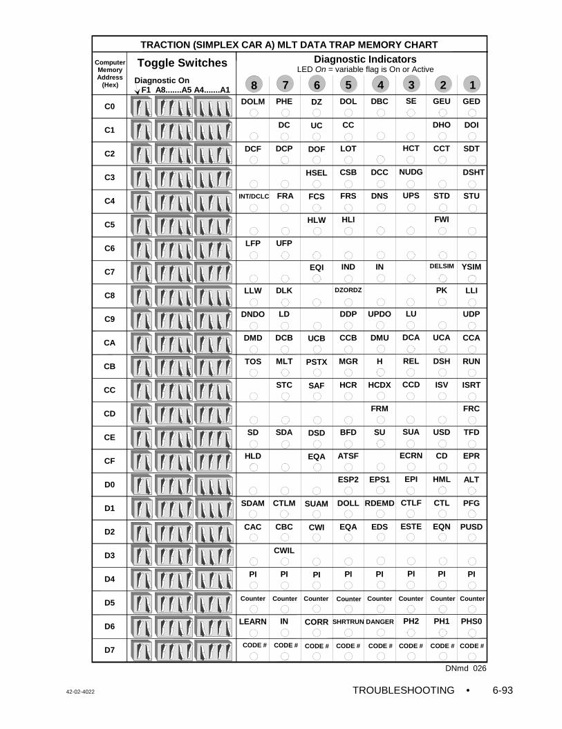
42-02-4022 TROUBLESHOOTING • 6-93
GED
DOI
SDT
DSHT
STU
YSIM
LLI
UDP
CCA
RUN
ISRT
FRC
TFD
EPR
ALT
PFG
PUSD
PI
PHS0
GEU
DHO
CCT
STD
FWI
PK
UCA
DSH
ISV
USD
CD
HML
CTL
EQN
PI
PH1
SE
HCT
NUDG
UPS
LU
DCA
REL
CCD
SUA
ECRN
EPI
CTLF
ESTE
PI
PH2
DBC
DCC
DNS
IN
UPDO
DMU
H
HCDX
FRM
SU
EPS1
RDEMD
EDS
PI
DOL
CC
LOT
CSB
FRS
HLI
IND
DDP
CCB
MGR
HCR
BFD
ATSF
ESP2
DOLL
EQA
PI
DZ
UC
DOF
HSEL
FCS
HLW
EQI
UCB
PSTX
SAF
DSD
EQA
SUAM
CWI
PI
CORR
PHE
DC
DCP
FRA
UFP
DLK
LD
DCB
MLT
STC
SDA
CTLM
CBC
CWIL
PI
IN
DOLM
DCF
LFP
LLW
DNDO
DMD
TOS
SD
HLD
SDAM
CAC
PI
LEARN
TRACTION (SIMPLEX CAR A) MLT DATA TRAP MEMORY CHART
ComputerMemoryAddress
(Hex)Diagnostic On F1 A8.......A5 A4.......A1
C0
C1
C2
C3
C4
C5
C6
C7
C8
C9
CA
CB
CC
CD
CE
CF
D0
D1
D2
D3
D4
D5
D6
D7
Diagnostic IndicatorsLED On = variable flag is On or Active
8
Toggle Switches
INT/DCLC
DZORDZ
DELSIM
DNmd 026
1234567
SHRTRUN DANGER
CODE #CODE #CODE # CODE #
Counter Counter Counter Counter Counter Counter
CODE # CODE # CODE # CODE #
Counter Counter


.
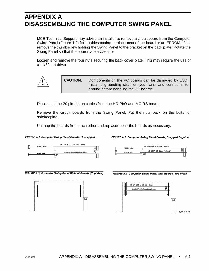
42-02-4022 APPENDIX A - DISASSEMBLING THE COMPUTER SWING PANEL • A-1
CAUTION: Components on the PC boards can be damaged by ESD.Install a grounding strap on your wrist and connect it toground before handling the PC boards.
APPENDIX A DISASSEMBLING THE COMPUTER SWING PANEL
MCE Technical Support may advise an installer to remove a circuit board from the ComputerSwing Panel (Figure 1.2) for troubleshooting, replacement of the board or an EPROM. If so,remove the thumbscrew holding the Swing Panel to the bracket on the back plate. Rotate theSwing Panel so that the boards are accessible.
Loosen and remove the four nuts securing the back cover plate. This may require the use ofa 11/32 nut driver.
Disconnect the 20 pin ribbon cables from the HC-PI/O and MC-RS boards.
Remove the circuit boards from the Swing Panel. Put the nuts back on the bolts forsafekeeping.
Unsnap the boards from each other and replace/repair the boards as necessary.
• APPENDIX B - CHANGING PC BOARDS OR EPROMS 42-02-4022A-2
CAUTION: Components on the PC boards can be damaged by ESD.Install a grounding strap on your wrist and connect it toground before handling the PC boards.
APPENDIX BCHANGING PC BOARDS OR EPROMS
With directions from MCE Technical Support, a PC board, EPROMs or Microcontroller mayneed to be reinstalled in the field. Great care should be taken when changing any of theseitems. The EPROM stores the computer program, the microcontroller both stores and executesthe program and all three are subject to damage by ESD (see CAUTION). These instructionsshould be followed step-by-step.
B.1 REPLACING THE MAIN PROCESSOR BOARD OR EPROMS
Normally the microprocessor on the Main Processor board (MC-MP2-2K) is not replaced in thefield. Sometimes the EPROM is replaced to upgrade the program and occasionally thecomplete board must be replaced due to a component failure.
Replacing the EPROM - The EPROM for the MC-MP2-2K board is labeled S-MP2-xx-1. The“xx” represents the controller type. If the new EPROM has the same job number as the oldEPROM, the user settings for timers and adjustable control variables, etc., are retained. Anynew timers or variables added to the new EPROM will be set to their default values.
If the job number on the new EPROM is different from the job number on the old EPROM, allof the timers and variables will be set to their default values. The user settings should bedocumented before the old EPROM is removed so that they can be re-entered when the newEPROM is installed.
Replacing the Main Processor board - The user settings for timer and adjustable controlvariables are stored in battery backed RAM on the Main Processor board. If the new board waspreviously installed in another car controller, the user settings from that car will be retained. Ifthe new board is a replacement from MCE, all of the user programmable values will be set totheir default values. Therefore, the current user settings should be documented before the oldboard is removed so that they can be re-entered when the new board is installed. The followingis a list of the user settings:
C Elevator Timers (see Section 5.2.3)C Real Time Clock Flags (see Section 5.2.4)C Communications Port Settings (see Section 5.3.1)C Security Codes (see Section 5.3.2)C Master Software Key (MSK) (see Section 5.3.3)C Software Options - Adjustable Control Variables (see Section 5.3.4)
42-02-4022 APPENDIX B - CHANGING PC BOARDS OR EPROMS • A-3
Replacement Procedure
1. Document the current settings for the items listed above.
2. Turn power OFF at the main disconnect and verify that no lights are operating on themicroprocessor panel. Install a grounding strap on your wrist and connect it to groundbefore handling the PC boards.
3. Remove the Main Processor board (MC-MP2) from the Swing Panel. Refer to AppendixA for instructions on unloading the boards from the Swing Panel. If you are replacingthe PC board, proceed to step 6 below (refer to Figure 6.22 MC-MP2 Board QuickReference) for proper jumper settings.
4. Using a small, thin-bladed screwdriver, place the tip between the EPROM chip and itssocket, not between the socket and the board (see Figure 6.22). Gently pry the existingEPROM out from the socket. Do this very slowly, taking care not to bend the leads. Ifthey become bent, straighten them carefully with needlenose pliers.
5. Place the new EPROM lightly (do not plug it in yet) into the socket and check to see thatall pins are aligned with their corresponding holes in the socket. Also make sure that thenotch on the end of the EPROM is correctly aligned with the notch on the socket (theorientation of the notch should also correspond to the notches on all of the other chipson the board). Now push the EPROM firmly into the socket and make sure that noneof the pins are bent during the insertion. Inspect the EPROM to make sure that no pinsare bent outward or under the EPROM.
6. Reassemble the Swing Panel assembly and close the Swing Panel. Refer to theinstructions in Appendix A.
7. Turn power ON at the main disconnect. Verify the proper operation of all boards byinspecting the diagnostic indicators and Computer ON LEDs on the individual processorboards.
C If the Computer ON LEDs are not illuminated on all boards, the EPROMs maynot have been installed properly. Repeat the above steps 2 through 7.
8. Re-enter the user settings documented in step 1 above.
B.2 REPLACING THE MC-CGP-4 (8) BOARD OR EPROMS
Sometimes the EPROMs are replaced to upgrade the program to a new software version andoccasionally the complete board must be replaced for a software upgrade or a componentfailure.
Replacing the EPROMs - The EPROMs for the MC-CGP-4 (8) board are labeled S-CGP-C-1and S-CGP-C-2. i) EPROMs with the same software version number will not cause the loss of user data.
Follow steps 2 thru 7 in the Replacement Procedure below. ii) EPROMs with a new software version number will result in loss of user data. Follow the
entire Replacement Procedure below.
Replacing the MC-CGP-4 (8) board - The user settings for the items listed below are storedin battery backed RAM on the MC-CGP-4 (8) board. If the new board was previously installedin another car controller, the user settings from that car will be retained. Follow the entire
• APPENDIX B - CHANGING PC BOARDS OR EPROMS 42-02-4022A-4
Replacement Procedure below when using a board from another car controller which hasdifferent settings from those of the car being replaced or when installing a board from MCE.
NOTE: The Fault Log and Performance Reports will all be lost and can not be recovered.
Replacement Procedure
1. Document the current settings for the items listed below.
C M3 Group Parameters or Car ID parameter CNID on F1 -1 screen for local cars onlyC Security - timer tables, security configurations, passenger names and access codes
(simplex car and group only)C Special Events Calendar Menu options Configure by Type, Configure by Controller,
and CMS Com Port Setup (if available)C Job Configuration data used for display - job name, car label and landing labels
2. Turn power OFF at the main disconnect and verify that no lights are operating on themicroprocessor panel. Install a grounding strap on your wrist and connect it to groundbefore handling the PC boards.
3. Remove the MC-CGP-4 (8) board from the Swing Panel. Refer to Appendix A forinstructions on unloading the boards from the Swing Panel. If you are replacing the PCboard, proceed to step 6 below (refer to Figure 6.23 MC-CGP-4 Board Quick Referencefor proper jumper settings).
4. The two EPROMs on the MC-CGP-4 (8) board are labeled ROM1-U17 and ROM2-U18(see Figure 6.23) Using a small, thin-bladed screwdriver, place the tip between theEPROM chip and its socket, not between the socket and the board. Gently pry theexisting EPROMs out from the socket. Do this very slowly, taking care not to bend theleads. If they become bent, straighten them carefully with a needlenose pliers.
5. Place the new EPROMs lightly (do not plug it in yet) into the sockets and check to seethat all pins are aligned with their corresponding holes in the socket. Also make surethat the notch on the end of the EPROM is correctly aligned with the notch on thesocket (the orientation of the notch should also correspond to the notches on all of theother chips on the board). Now push the EPROMs firmly into the socket and make surethat none of the pins are bent during the insertion. Inspect the EPROMs to make surethat no pins are bent outward or under the EPROM.
6. Reassemble the Swing Panel assembly and close the Swing Panel. Refer to theinstructions in Appendix A.
7. Turn power ON at the main disconnect. Verify the proper operation of all boards byinspecting the diagnostic indicators and Computer ON LEDs on the individual processorboards.
C If the Computer ON LEDs are not illuminated on all boards, the EPROMs maynot have been installed properly. Repeat the above steps 2 through 7.
C Verify that the group controller is communicating with the cars by looking at theLEDs in the front of the group swing panel.
8. Set ODPC=ON, on the General F1-1 screen, and save the parameter, or reset theMC-CGP parameters as described in Section 5.2.6.
9. Re-enter the user settings documented in step 1 above.
42-02-4022 APPENDIX B - CHANGING PC BOARDS OR EPROMS • A-5
CAUTION: Components on the PC boards can be damaged by ESD.Wear an ESD grounding strap on your wrist and connect it toground before handling the PC boards.
B.3 REPLACING THE EPROM ON THE SMARTLINK MC-NC / MC-NIO BOARD
With directions from MCE Technical Support, an EPROM may need to be reinstalled in thefield. Great care should be taken as printed circuit (PC) boards and integrated circuits (ICs),such as an EPROM, are subject to damage by ESD (see CAUTION). These instructionsshould be followed step-by-step.
Identification of the EPROMs - The EPROM for the MC-NC board is labeled S-NC-C (seeFigure G.9, MC-NC Board Quick Reference). The EPROM for the MC-NIO board is labeledS-NIO-C (see Figure G.10, MC-NIO Board Quick Reference).
Replacement Procedure
1. Turn controller power OFF and verify that no lights are operating on the processorboards. Wear an ESD grounding strap on your wrist and connect it to ground beforehandling the PC boards.
2. Using a small, thin-bladed screwdriver, place the tip between the EPROM chip and itssocket (not between the socket and the board). Gently pry the existing EPROM outfrom the socket. Do this very slowly, taking care not to bend the leads.
3. Position the new EPROM into the socket (do not plug it in yet) and check to see that allpins are aligned with their corresponding holes in the socket. Also make sure that thenotch on the end of the EPROM is correctly aligned with the notch on the socket (thenotch orientation of all the ICs on the board are the same). Once these checks havebeen made, push the EPROM slowly, evenly and firmly into the socket and make surethat the pins are not bent during the insertion. Inspect the EPROM for pins bentoutward or under the EPROM and correct any bent pins found.
4. Disconnect Network cable NETA and NETB. Turn power ON. Verify the properoperation of the board by inspecting the diagnostic indicators (COMPUTER ON andSERVICE LEDs) on the respective processor boards:
MC-NC Board - If installed properly, the COMPUTER ON LED will be ON continuouslyand the SERVICE LED will be OFF, plus both will blink together approximately onceevery 10 seconds. This pattern repeats continuously. If the EPROM has been installedincorrectly, both the Computer ON and the SERVICE LEDs will blink simultaneouslyonce per second. A similar pattern is observed if no EPROM is installed. Repeat theabove steps 1 through 3. Check for notch orientation and look for bent pins.
MC-NIO Board - If properly installed, the SERVICE LED should not illuminate and theCOMPUTER ON LED should stay ON continuously. If the SERVICE LED staysilluminated, the EPROM may not be installed properly. Repeat the above steps 1through 3. Check for notch orientation and look for bent pins.
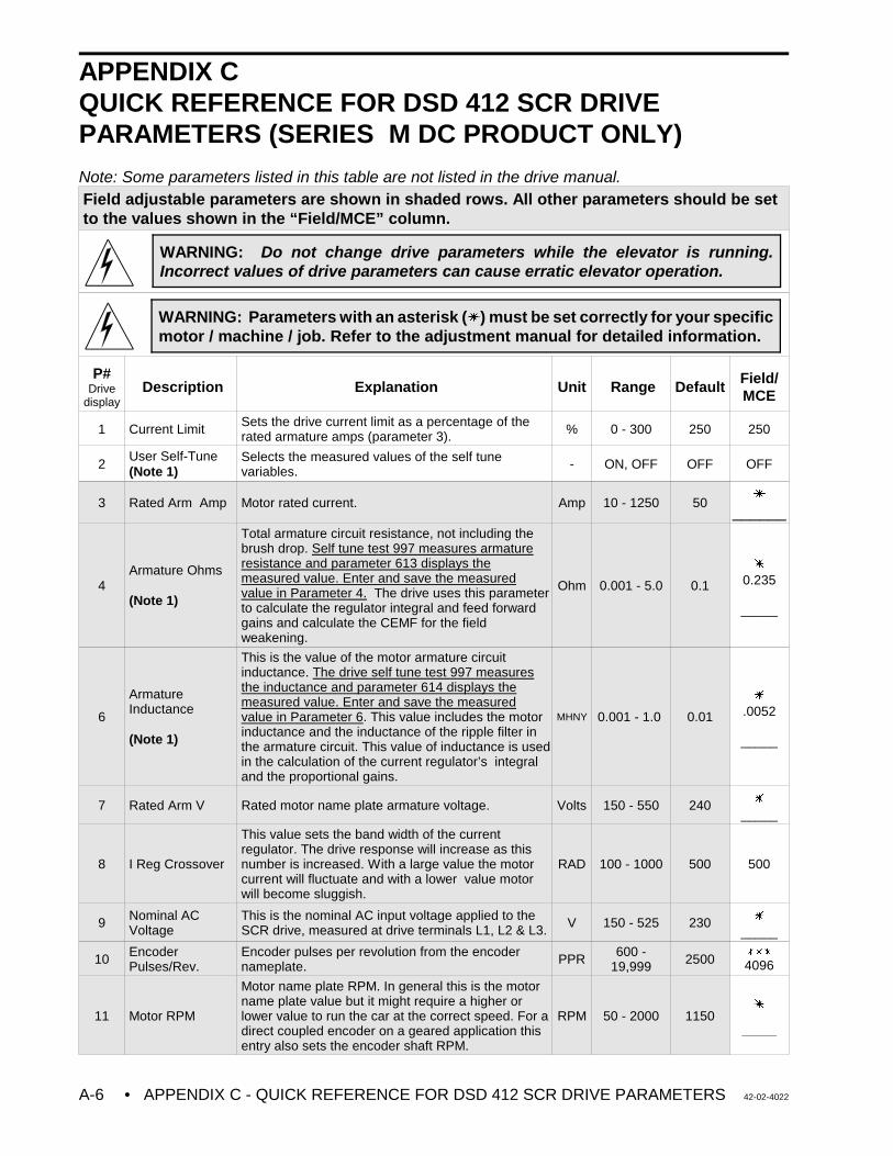
• APPENDIX C - QUICK REFERENCE FOR DSD 412 SCR DRIVE PARAMETERS 42-02-4022A-6
WARNING: Do not change drive parameters while the elevator is running.Incorrect values of drive parameters can cause erratic elevator operation.
WARNING: Parameters with an asterisk (u) must be set correctly for your specificmotor / machine / job. Refer to the adjustment manual for detailed information.
APPENDIX CQUICK REFERENCE FOR DSD 412 SCR DRIVEPARAMETERS (SERIES M DC PRODUCT ONLY)
Note: Some parameters listed in this table are not listed in the drive manual.Field adjustable parameters are shown in shaded rows. All other parameters should be setto the values shown in the “Field/MCE” column.
P#Drive
displayDescription Explanation Unit Range Default
Field/MCE
1 Current Limit Sets the drive current limit as a percentage of therated armature amps (parameter 3). % 0 - 300 250 250
2User Self-Tune(Note 1)
Selects the measured values of the self tunevariables. - ON, OFF OFF OFF
3 Rated Arm Amp Motor rated current. Amp 10 - 1250 50u
______
4Armature Ohms
(Note 1)
Total armature circuit resistance, not including thebrush drop. Self tune test 997 measures armatureresistance and parameter 613 displays themeasured value. Enter and save the measuredvalue in Parameter 4. The drive uses this parameterto calculate the regulator integral and feed forwardgains and calculate the CEMF for the fieldweakening.
Ohm 0.001 - 5.0 0.1
u
0.235
_____
6
ArmatureInductance
(Note 1)
This is the value of the motor armature circuitinductance. The drive self tune test 997 measuresthe inductance and parameter 614 displays themeasured value. Enter and save the measuredvalue in Parameter 6. This value includes the motorinductance and the inductance of the ripple filter inthe armature circuit. This value of inductance is usedin the calculation of the current regulator’s integraland the proportional gains.
MHNY 0.001 - 1.0 0.01
u
.0052
_____
7 Rated Arm V Rated motor name plate armature voltage. Volts 150 - 550 240 u
_____
8 I Reg Crossover
This value sets the band width of the currentregulator. The drive response will increase as thisnumber is increased. With a large value the motorcurrent will fluctuate and with a lower value motorwill become sluggish.
RAD 100 - 1000 500 500
9 Nominal ACVoltage
This is the nominal AC input voltage applied to theSCR drive, measured at drive terminals L1, L2 & L3. V 150 - 525 230 u
_____
10 EncoderPulses/Rev.
Encoder pulses per revolution from the encodernameplate. PPR 600 -
19,999 2500uuu
4096
11 Motor RPM
Motor name plate RPM. In general this is the motorname plate value but it might require a higher orlower value to run the car at the correct speed. For adirect coupled encoder on a geared application thisentry also sets the encoder shaft RPM.
RPM 50 - 2000 1150u
______
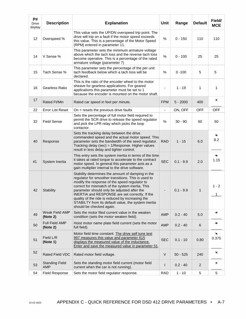
P#Drive
displayDescription Explanation Unit Range Default
Field/MCE
42-02-4022 APPENDIX C - QUICK REFERENCE FOR DSD 412 DRIVE PARAMETERS • A-7
12 Overspeed %
This value sets the UP/DN overspeed trip point. Thedrive will trip on a fault if the motor speed exceedsthis value. This is a percentage of the Motor Speed(RPM) entered in parameter 11.
% 0 - 150 110 110
14 V Sense %
This parameter sets the minimum armature voltageabove which the tach loss and the reverse tach lossbecome operative. This is a percentage of the ratedarmature voltage (parameter 7)
% 0 - 100 25 25
15 Tach Sense %This parameter sets the percentage of the per unittach feedback below which a tach loss will bedeclared.
% 0 -100 5 5
16 Gearless Ratio
This is the ratio of the encoder wheel to the motorsheave for gearless applications. For gearedapplications this parameter must be set to 1because the encoder is mounted on the motor shaft.
- 1 - 19 1 1
17 Rated Ft/Min Rated car speed in feet per minute. FPM 5 - 2000 400 u
_____
22 Error List Reset On = resets the previous drive faults - ON, OFF OFF OFF
32 Field Sense
Sets the percentage of full motor field required topermit the SCR drive to release the speed regulatorand pick the LPR relay which picks the loopcontactor.
% 30 - 90 60 50
40 Response
Sets the tracking delay between the drivecommanded speed and the actual motor speed. Thisparameter sets the bandwidth of the seed regulator. Tracking delay (sec) = 1/Response. Higher valuesresult in less delay and tighter control.
RAD 1 - 15 6.0
u
8.2
_____
41 System Inertia
This entry sets the system inertia in terms of the timeit takes at rated torque to accelerate to the contractmotor speed. In general this parameter acts as again multiplier internal to the drive software.
SEC 0.1 - 9.9 2.0
u
1.15
_____
42 Stability
Stability determines the amount of damping in theregulator for smoother transitions. This is used tomodify the response of the speed regulator tocorrect for mismatch of the system inertia. Thisparameter should only be adjusted after theINERTIA and RESPONSE are set correctly. If thequality of the ride is reduced by increasing theSTABILTY from its default value, the system inertiashould be checked again.
- 0.1 - 9.9 11 - 2
1
49Weak Field AMP(Note 2)
Sets the motor filed current value in the weakencondition (sets the motor weaken field). AMP 0.2 - 40 5.0 u
_____
50Full Field AMP(Note 2)
Hoist motor name plate field current (sets the motor full field). AMP 0.2 - 40 6 u
_____
51Field L/R(Note 1)
Motor field time constant. The drive self tune test997 measures this value and parameter 615displays the measured value of the inductance.Enter and save the measured value in parameter 51.
SEC 0.1 - 10 0.80
u
0.375
_____
52 Rated Field VDC Rated motor field voltage. V 50 - 525 240 u
_____
53 Standing FieldAMP
Sets the standing motor field current (motor fieldcurrent when the car is not running). I 0.2 - 40 2 u
_____
54 Field Response Sets the motor field regulator response. RAD 1 - 10 5 5
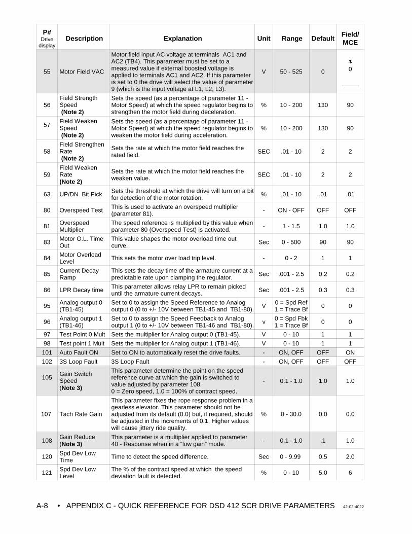
P#Drive
displayDescription Explanation Unit Range Default
Field/MCE
• APPENDIX C - QUICK REFERENCE FOR DSD 412 SCR DRIVE PARAMETERS 42-02-4022A-8
55 Motor Field VAC
Motor field input AC voltage at terminals AC1 andAC2 (TB4). This parameter must be set to ameasured value if external boosted voltage isapplied to terminals AC1 and AC2. If this parameteris set to 0 the drive will select the value of parameter9 (which is the input voltage at L1, L2, L3).
V 50 - 525 0
u
0
_____
56Field StrengthSpeed (Note 2)
Sets the speed (as a percentage of parameter 11 -Motor Speed) at which the speed regulator begins tostrengthen the motor field during deceleration.
% 10 - 200 130 90
57Field WeakenSpeed (Note 2)
Sets the speed (as a percentage of parameter 11 -Motor Speed) at which the speed regulator begins toweaken the motor field during acceleration.
% 10 - 200 130 90
58Field StrengthenRate (Note 2)
Sets the rate at which the motor field reaches therated field. SEC .01 - 10 2 2
59Field WeakenRate(Note 2)
Sets the rate at which the motor field reaches theweaken value. SEC .01 - 10 2 2
63 UP/DN Bit Pick Sets the threshold at which the drive will turn on a bitfor detection of the motor rotation. % .01 - 10 .01 .01
80 Overspeed Test This is used to activate an overspeed multiplier(parameter 81). - ON - OFF OFF OFF
81 OverspeedMultiplier
The speed reference is multiplied by this value whenparameter 80 (Overspeed Test) is activated. - 1 - 1.5 1.0 1.0
83 Motor O.L. TimeOut
This value shapes the motor overload time outcurve. Sec 0 - 500 90 90
84 Motor OverloadLevel This sets the motor over load trip level. - 0 - 2 1 1
85 Current DecayRamp
This sets the decay time of the armature current at apredictable rate upon clamping the regulator. Sec .001 - 2.5 0.2 0.2
86 LPR Decay time This parameter allows relay LPR to remain pickeduntil the armature current decays. Sec .001 - 2.5 0.3 0.3
95 Analog output 0(TB1-45)
Set to 0 to assign the Speed Reference to Analogoutput 0 (0 to +/- 10V between TB1-45 and TB1-80). V 0 = Spd Ref
1 = Trace Bf 0 0
96 Analog output 1(TB1-46)
Set to 0 to assign the Speed Feedback to Analogoutput 1 (0 to +/- 10V between TB1-46 and TB1-80). v 0 = Spd Fbk
1 = Trace Bf 0 0
97 Test Point 0 Mult Sets the multiplier for Analog output 0 (TB1-45). V 0 - 10 1 1
98 Test point 1 Mult Sets the multiplier for Analog output 1 (TB1-46). V 0 - 10 1 1
101 Auto Fault ON Set to ON to automatically reset the drive faults. - ON, OFF OFF ON
102 3S Loop Fault 3S Loop Fault - ON, OFF OFF OFF
105Gain SwitchSpeed(Note 3)
This parameter determine the point on the speedreference curve at which the gain is switched tovalue adjusted by parameter 108.0 = Zero speed, 1.0 = 100% of contract speed.
- 0.1 - 1.0 1.0 1.0
107 Tach Rate Gain
This parameter fixes the rope response problem in agearless elevator. This parameter should not beadjusted from its default (0.0) but, if required, shouldbe adjusted in the increments of 0.1. Higher valueswill cause jittery ride quality.
% 0 - 30.0 0.0 0.0
108Gain Reduce(Note 3)
This parameter is a multiplier applied to parameter40 - Response when in a “low gain” mode. - 0.1 - 1.0 .1 1.0
120 Spd Dev LowTime Time to detect the speed difference. Sec 0 - 9.99 0.5 2.0
121 Spd Dev LowLevel
The % of the contract speed at which the speeddeviation fault is detected. % 0 - 10 5.0 6
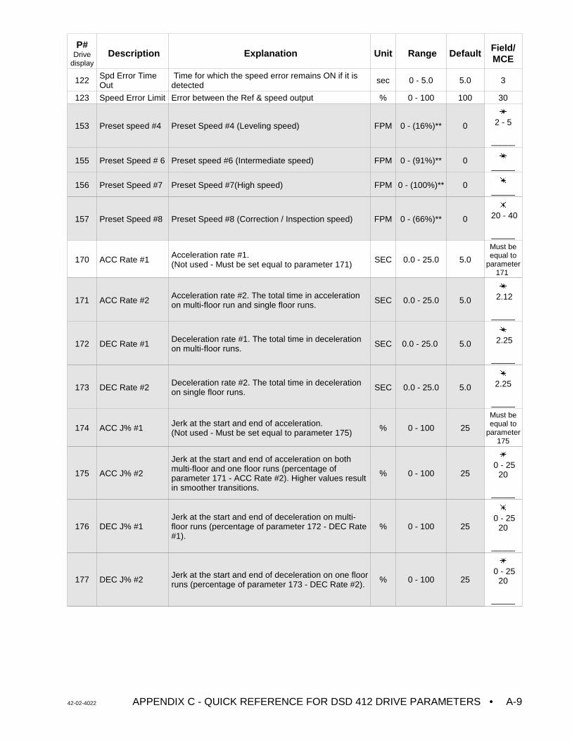
P#Drive
displayDescription Explanation Unit Range Default
Field/MCE
42-02-4022 APPENDIX C - QUICK REFERENCE FOR DSD 412 DRIVE PARAMETERS • A-9
122 Spd Error TimeOut
Time for which the speed error remains ON if it isdetected sec 0 - 5.0 5.0 3
123 Speed Error Limit Error between the Ref & speed output % 0 - 100 100 30
153 Preset speed #4 Preset Speed #4 (Leveling speed) FPM 0 - (16%)** 0
u
2 - 5
_____
155 Preset Speed # 6 Preset speed #6 (Intermediate speed) FPM 0 - (91%)** 0 u
_____
156 Preset Speed #7 Preset Speed #7(High speed) FPM 0 - (100%)** 0 u
_____
157 Preset Speed #8 Preset Speed #8 (Correction / Inspection speed) FPM 0 - (66%)** 0
u
20 - 40
_____
170 ACC Rate #1 Acceleration rate #1. (Not used - Must be set equal to parameter 171) SEC 0.0 - 25.0 5.0
Must beequal to
parameter171
171 ACC Rate #2 Acceleration rate #2. The total time in accelerationon multi-floor run and single floor runs. SEC 0.0 - 25.0 5.0
u
2.12
_____
172 DEC Rate #1 Deceleration rate #1. The total time in decelerationon multi-floor runs. SEC 0.0 - 25.0 5.0
u
2.25
_____
173 DEC Rate #2 Deceleration rate #2. The total time in decelerationon single floor runs. SEC 0.0 - 25.0 5.0
u
2.25
_____
174 ACC J% #1 Jerk at the start and end of acceleration. (Not used - Must be set equal to parameter 175) % 0 - 100 25
Must beequal to
parameter175
175 ACC J% #2
Jerk at the start and end of acceleration on bothmulti-floor and one floor runs (percentage ofparameter 171 - ACC Rate #2). Higher values resultin smoother transitions.
% 0 - 100 25
u
0 - 2520
_____
176 DEC J% #1Jerk at the start and end of deceleration on multi-floor runs (percentage of parameter 172 - DEC Rate#1).
% 0 - 100 25
u
0 - 2520
_____
177 DEC J% #2 Jerk at the start and end of deceleration on one floorruns (percentage of parameter 173 - DEC Rate #2). % 0 - 100 25
u
0 - 2520
_____
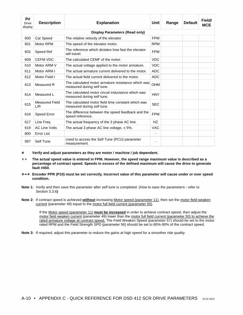
P#Drive
displayDescription Explanation Unit Range Default
Field/MCE
• APPENDIX C - QUICK REFERENCE FOR DSD 412 SCR DRIVE PARAMETERS 42-02-4022A-10
Display Parameters (Read only)
600 Car Speed The relative velocity of the elevator. FPM
601 Motor RPM The speed of the elevator motor. RPM
602 Speed Ref The reference which dictates how fast the elevatorwill travel. FPM
609 CEFM VDC The calculated CEMF of the motor. VDC
610 Motor ARM V The actual voltage applied to the motor armature. VDC
611 Motor ARM I The actual armature current delivered to the motor. ADC
612 Motor Field I The actual field current delivered to the motor. ADC
613 Measured R The calculated motor armature resistance which wasmeasured during self tune. OHM
614 Measured L The calculated motor circuit inductance which wasmeasured during self tune. HNY
615 Measured FieldL/R
The calculated motor field time constant which wasmeasured during self tune. SEC
616 Speed Error The difference between the speed feedback and thespeed reference. FPM
617 Line Freq The actual frequency of the 3 phase AC line. HZ
619 AC Line Volts The actual 3 phase AC line voltage, ± 5%. VAC
800 Error List -
997 Self Tune Used to access the Self Tune (PCU) parametermeasurement. -
u Verify and adjust parameters as they are motor / machine / job dependent.
uu The actual speed value is entered in FPM. However, the speed range maximum value is described as apercentage of contract speed. Speeds in excess of the defined maximum will cause the drive to generatefault #450.
uuu Encoder PPR (P10) must be set correctly. Incorrect value of this parameter will cause under or over speedcondition.
Note 1: Verify and then save this parameter after self tune is completed. (How to save the parameters - refer toSection 3.3.6)
Note 2: If contract speed is achieved without increasing Motor speed (parameter 11), then set the motor field weakencurrent (parameter 49) equal to the motor full field current (parameter 50).
If the Motor speed (parameter 11) must be increased in order to achieve contract speed, then adjust themotor field weaken current (parameter 49) lower than the motor full field current (parameter 50) to achieve therated armature voltage at contract speed. The Field Weaken Speed (parameter 57) should be set to the motorrated RPM and the Field Strength SPD (parameter 56) should be set to 80%-90% of the contract speed.
Note 3: If required, adjust this parameter to reduce the gains at high speed for a smoother ride quality.
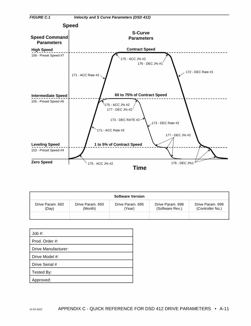
42-02-4022 APPENDIX C - QUICK REFERENCE FOR DSD 412 DRIVE PARAMETERS • A-11
Speed
TimeZero Speed
Leveling Speed
Intermediate Speed
High Speed
171 - ACC Rate #2172 - DEC Rate #1
175 - ACC J% #2
Contract Speed
1 to 5% of Contract Speed
Speed CommandParameters
S-CurveParameters
60 to 75% of Contract Speed
156 - Preset Speed #7
155 - Preset Speed #6
153 - Preset Speed #4
176 - DEC J% #1
171 - ACC Rate #2
175 - ACC J% #2
176 - DEC J%1
173 - DEC Rate #2
177 - DEC J% #2
175 - ACC J% #2
173 - DEC RATE #2
177 - DEC J% #2
FIGURE C.1 Velocity and S Curve Parameters (DSD 412)
Software Version
Drive Param. 692(Day)
Drive Param. 693(Month)
Drive Param. 695(Year)
Drive Param. 698(Software Rev.)
Drive Param. 699(Controller No.)
Job #:
Prod. Order #:
Drive Manufacturer:
Drive Model #:
Drive Serial #
Tested By:
Approved:
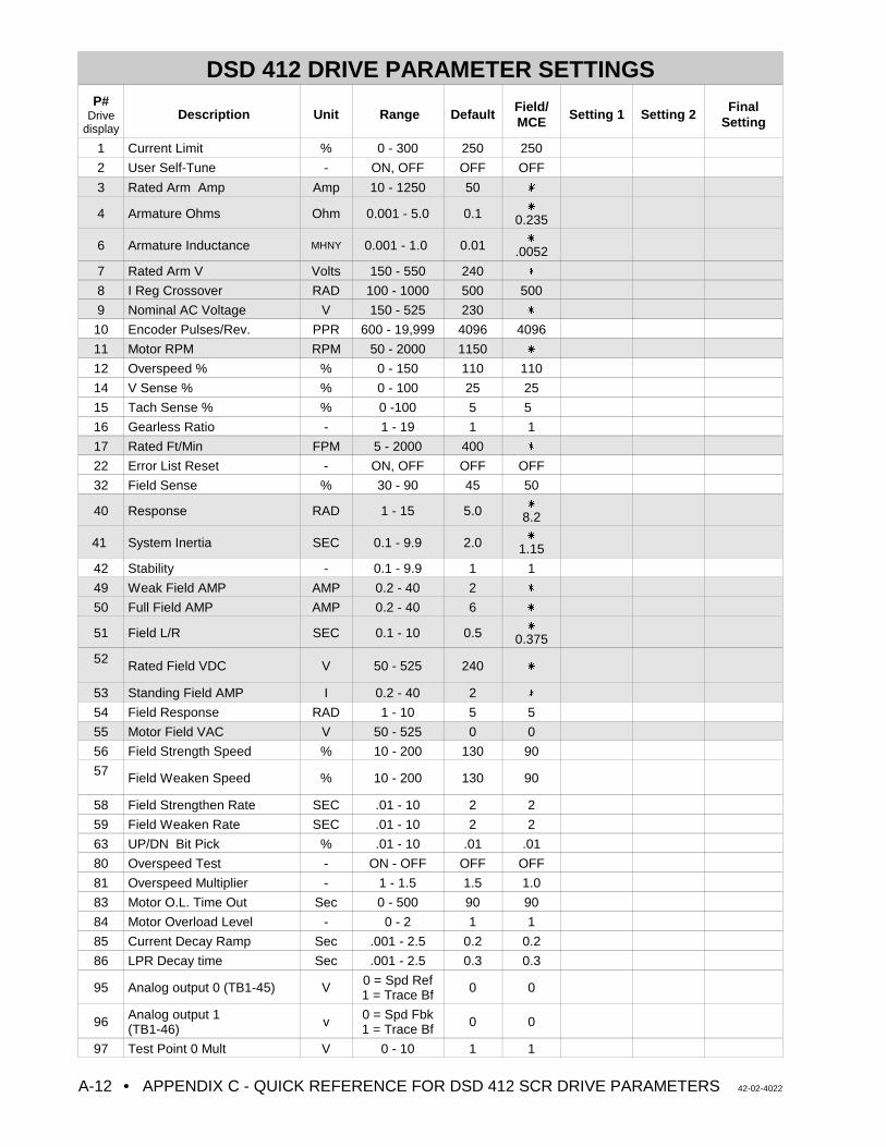
• APPENDIX C - QUICK REFERENCE FOR DSD 412 SCR DRIVE PARAMETERS 42-02-4022A-12
DSD 412 DRIVE PARAMETER SETTINGSP#
Drivedisplay
Description Unit Range DefaultField/MCE
Setting 1 Setting 2Final
Setting
1 Current Limit % 0 - 300 250 250
2 User Self-Tune - ON, OFF OFF OFF
3 Rated Arm Amp Amp 10 - 1250 50 u
4 Armature Ohms Ohm 0.001 - 5.0 0.1u
0.235
6 Armature Inductance MHNY 0.001 - 1.0 0.01u
.0052
7 Rated Arm V Volts 150 - 550 240 u
8 I Reg Crossover RAD 100 - 1000 500 500
9 Nominal AC Voltage V 150 - 525 230 u
10 Encoder Pulses/Rev. PPR 600 - 19,999 4096 4096
11 Motor RPM RPM 50 - 2000 1150 u
12 Overspeed % % 0 - 150 110 110
14 V Sense % % 0 - 100 25 25
15 Tach Sense % % 0 -100 5 5
16 Gearless Ratio - 1 - 19 1 1
17 Rated Ft/Min FPM 5 - 2000 400 u
22 Error List Reset - ON, OFF OFF OFF
32 Field Sense % 30 - 90 45 50
40 Response RAD 1 - 15 5.0u
8.2
41 System Inertia SEC 0.1 - 9.9 2.0u
1.15
42 Stability - 0.1 - 9.9 1 1
49 Weak Field AMP AMP 0.2 - 40 2 u
50 Full Field AMP AMP 0.2 - 40 6 u
51 Field L/R SEC 0.1 - 10 0.5u
0.375
52 Rated Field VDC V 50 - 525 240 u
53 Standing Field AMP I 0.2 - 40 2 u
54 Field Response RAD 1 - 10 5 5
55 Motor Field VAC V 50 - 525 0 0
56 Field Strength Speed % 10 - 200 130 90
57 Field Weaken Speed % 10 - 200 130 90
58 Field Strengthen Rate SEC .01 - 10 2 2
59 Field Weaken Rate SEC .01 - 10 2 2
63 UP/DN Bit Pick % .01 - 10 .01 .01
80 Overspeed Test - ON - OFF OFF OFF
81 Overspeed Multiplier - 1 - 1.5 1.5 1.0
83 Motor O.L. Time Out Sec 0 - 500 90 90
84 Motor Overload Level - 0 - 2 1 1
85 Current Decay Ramp Sec .001 - 2.5 0.2 0.2
86 LPR Decay time Sec .001 - 2.5 0.3 0.3
95 Analog output 0 (TB1-45) V 0 = Spd Ref1 = Trace Bf 0 0
96 Analog output 1(TB1-46) v 0 = Spd Fbk
1 = Trace Bf 0 0
97 Test Point 0 Mult V 0 - 10 1 1
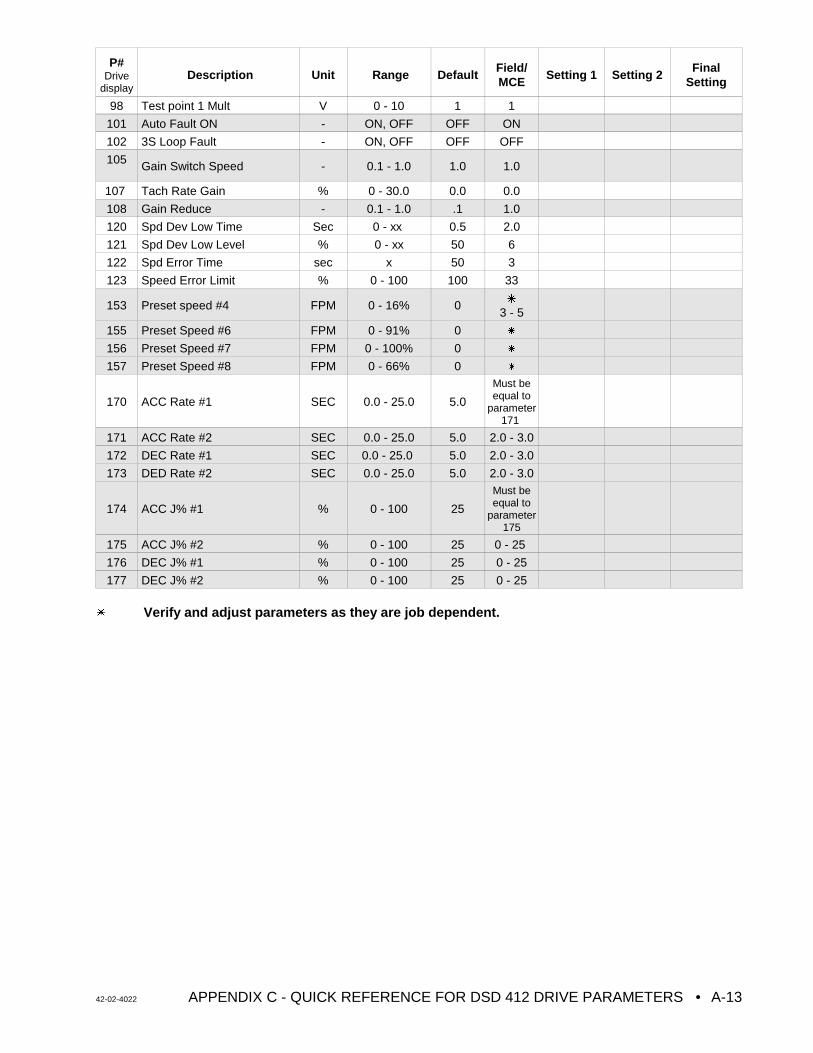
P#Drive
displayDescription Unit Range Default
Field/MCE
Setting 1 Setting 2Final
Setting
42-02-4022 APPENDIX C - QUICK REFERENCE FOR DSD 412 DRIVE PARAMETERS • A-13
98 Test point 1 Mult V 0 - 10 1 1
101 Auto Fault ON - ON, OFF OFF ON
102 3S Loop Fault - ON, OFF OFF OFF
105 Gain Switch Speed - 0.1 - 1.0 1.0 1.0
107 Tach Rate Gain % 0 - 30.0 0.0 0.0
108 Gain Reduce - 0.1 - 1.0 .1 1.0
120 Spd Dev Low Time Sec 0 - xx 0.5 2.0
121 Spd Dev Low Level % 0 - xx 50 6
122 Spd Error Time sec x 50 3
123 Speed Error Limit % 0 - 100 100 33
153 Preset speed #4 FPM 0 - 16% 0 u
3 - 5
155 Preset Speed #6 FPM 0 - 91% 0 u
156 Preset Speed #7 FPM 0 - 100% 0 u
157 Preset Speed #8 FPM 0 - 66% 0 u
170 ACC Rate #1 SEC 0.0 - 25.0 5.0
Must beequal to
parameter171
171 ACC Rate #2 SEC 0.0 - 25.0 5.0 2.0 - 3.0
172 DEC Rate #1 SEC 0.0 - 25.0 5.0 2.0 - 3.0
173 DED Rate #2 SEC 0.0 - 25.0 5.0 2.0 - 3.0
174 ACC J% #1 % 0 - 100 25
Must beequal to
parameter175
175 ACC J% #2 % 0 - 100 25 0 - 25
176 DEC J% #1 % 0 - 100 25 0 - 25
177 DEC J% #2 % 0 - 100 25 0 - 25
u Verify and adjust parameters as they are job dependent.
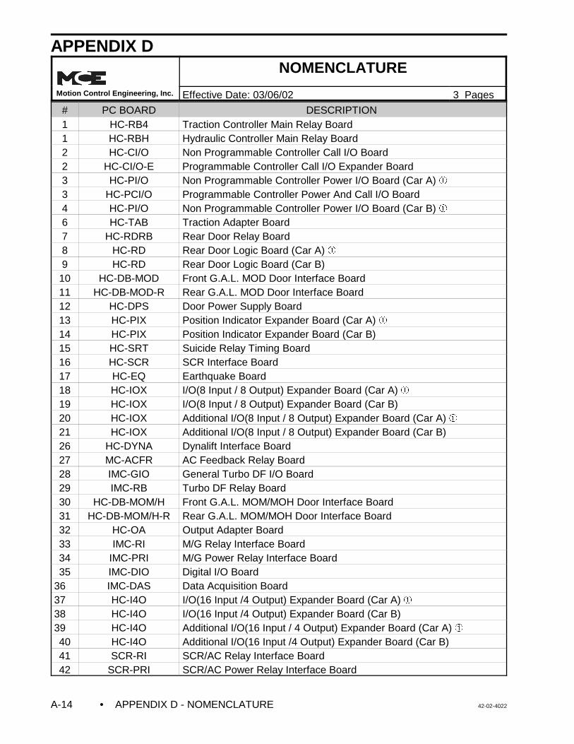
• APPENDIX D - NOMENCLATURE 42-02-4022A-14
APPENDIX DNOMENCLATURE
Motion Control Engineering, Inc. Effective Date: 03/06/02 3 Pages
# PC BOARD DESCRIPTION 1 HC-RB4 Traction Controller Main Relay Board1 HC-RBH Hydraulic Controller Main Relay Board2 HC-CI/O Non Programmable Controller Call I/O Board2 HC-CI/O-E Programmable Controller Call I/O Expander Board3 HC-PI/O Non Programmable Controller Power I/O Board (Car A) â3 HC-PCI/O Programmable Controller Power And Call I/O Board4 HC-PI/O Non Programmable Controller Power I/O Board (Car B) â6 HC-TAB Traction Adapter Board7 HC-RDRB Rear Door Relay Board8 HC-RD Rear Door Logic Board (Car A) â9 HC-RD Rear Door Logic Board (Car B)
10 HC-DB-MOD Front G.A.L. MOD Door Interface Board11 HC-DB-MOD-R Rear G.A.L. MOD Door Interface Board12 HC-DPS Door Power Supply Board13 HC-PIX Position Indicator Expander Board (Car A) â14 HC-PIX Position Indicator Expander Board (Car B)15 HC-SRT Suicide Relay Timing Board16 HC-SCR SCR Interface Board17 HC-EQ Earthquake Board18 HC-IOX I/O(8 Input / 8 Output) Expander Board (Car A) â19 HC-IOX I/O(8 Input / 8 Output) Expander Board (Car B)20 HC-IOX Additional I/O(8 Input / 8 Output) Expander Board (Car A) â21 HC-IOX Additional I/O(8 Input / 8 Output) Expander Board (Car B)26 HC-DYNA Dynalift Interface Board27 MC-ACFR AC Feedback Relay Board28 IMC-GIO General Turbo DF I/O Board29 IMC-RB Turbo DF Relay Board30 HC-DB-MOM/H Front G.A.L. MOM/MOH Door Interface Board31 HC-DB-MOM/H-R Rear G.A.L. MOM/MOH Door Interface Board32 HC-OA Output Adapter Board33 IMC-RI M/G Relay Interface Board34 IMC-PRI M/G Power Relay Interface Board35 IMC-DIO Digital I/O Board
36 IMC-DAS Data Acquisition Board37 HC-I4O I/O(16 Input /4 Output) Expander Board (Car A) â38 HC-I4O I/O(16 Input /4 Output) Expander Board (Car B)39 HC-I4O Additional I/O(16 Input / 4 Output) Expander Board (Car A) â40 HC-I4O Additional I/O(16 Input /4 Output) Expander Board (Car B)41 SCR-RI SCR/AC Relay Interface Board42 SCR-PRI SCR/AC Power Relay Interface Board
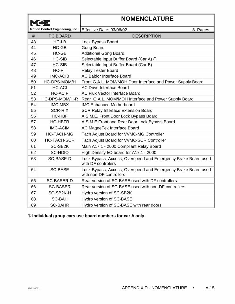
NOMENCLATURE
Motion Control Engineering, Inc. Effective Date: 03/06/02 3 Pages
# PC BOARD DESCRIPTION
42-02-4022 APPENDIX D - NOMENCLATURE • A-15
43 HC-LB Lock Bypass Board44 HC-GB Gong Board45 HC-GB Additional Gong Board46 HC-SIB Selectable Input Buffer Board (Car A) â47 HC-SIB Selectable Input Buffer Board (Car B)48 HC-RT Relay Tester Board49 IMC-ACIB AC Baldor Interface Board50 HC-DPS-MOM/H Front G.A.L. MOM/MOH Door Interface and Power Supply Board51 HC-ACI AC Drive Interface Board52 HC-ACIF AC Flux Vector Interface Board53 HC-DPS-MOM/H-R Rear G.A.L. MOM/MOH Interface and Power Supply Board54 IMC-MBX IMC Enhanced Motherboard55 SCR-RIX SCR Relay Interface Extension Board56 HC-HBF A.S.M.E. Front Door Lock Bypass Board57 HC-HBFR A.S.M.E Front and Rear Door Lock Bypass Board
58 IMC-ACIM AC MagneTek Interface Board
59 HC-TACH-MG Tach Adjust Board for VVMC-MG Controller
60 HC-TACH-SCR Tach Adjust Board for VVMC-SCR Controller
61 SC-SB2K Main A17.1 - 2000 Compliant Relay Board
62 SC-HDIO High Density I/O board for A17.1 - 2000
63 SC-BASE-D Lock Bypass, Access, Overspeed and Emergency Brake Board usedwith DF controlers
64 SC-BASE Lock Bypass, Access, Overspeed and Emergency Brake Board usedwith non-DF controllers
65 SC-BASER-D Rear version of SC-BASE used with DF controllers
66 SC-BASER Rear version of SC-BASE used with non-DF controllers
67 SC-SB2K-H Hydro version of SC-SB2K
68 SC-BAH Hydro version of SC-BASE
69 SC-BAHR Hydro version of SC-BASE with rear doors
â Individual group cars use board numbers for car A only
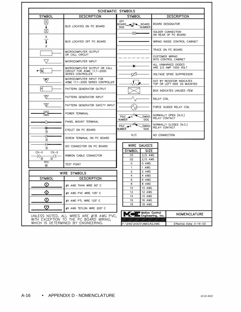
• APPENDIX D - NOMENCLATURE 42-02-4022A-16
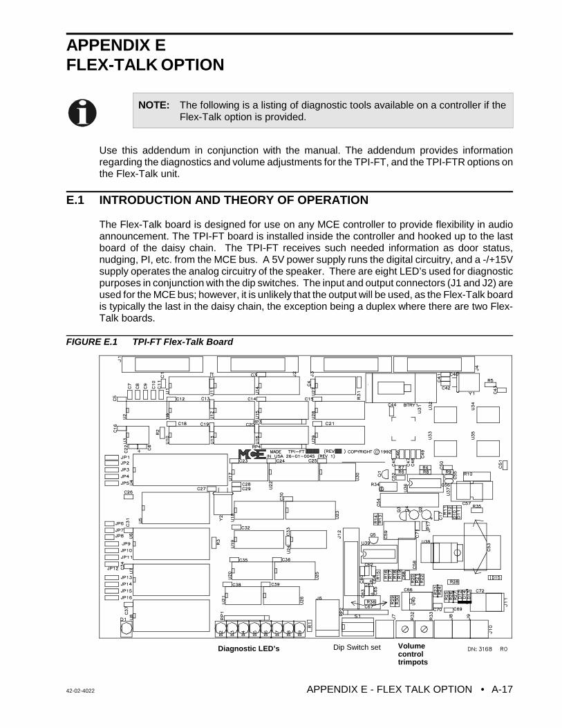
42-02-4022 APPENDIX E - FLEX TALK OPTION • A-17
NOTE: The following is a listing of diagnostic tools available on a controller if theFlex-Talk option is provided.
Diagnostic LED’s Dip Switch set Volumecontroltrimpots
APPENDIX E FLEX-TALK OPTION
Use this addendum in conjunction with the manual. The addendum provides informationregarding the diagnostics and volume adjustments for the TPI-FT, and the TPI-FTR options onthe Flex-Talk unit.
E.1 INTRODUCTION AND THEORY OF OPERATION
The Flex-Talk board is designed for use on any MCE controller to provide flexibility in audioannouncement. The TPI-FT board is installed inside the controller and hooked up to the lastboard of the daisy chain. The TPI-FT receives such needed information as door status,nudging, PI, etc. from the MCE bus. A 5V power supply runs the digital circuitry, and a -/+15Vsupply operates the analog circuitry of the speaker. There are eight LED’s used for diagnosticpurposes in conjunction with the dip switches. The input and output connectors (J1 and J2) areused for the MCE bus; however, it is unlikely that the output will be used, as the Flex-Talk boardis typically the last in the daisy chain, the exception being a duplex where there are two Flex-Talk boards.
FIGURE E.1 TPI-FT Flex-Talk Board
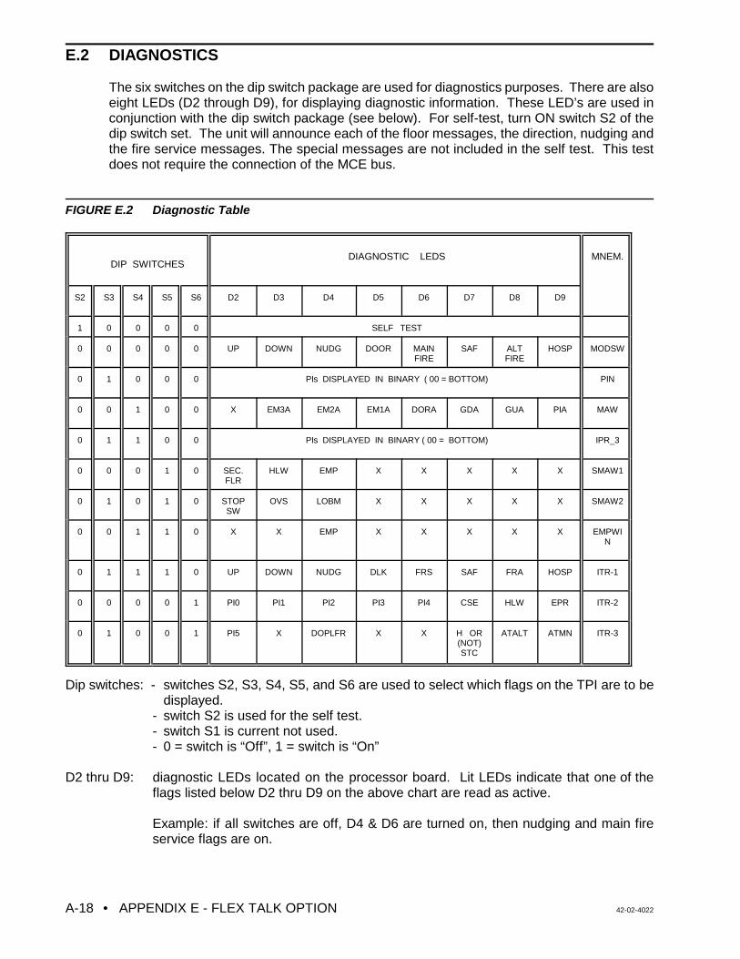
• APPENDIX E - FLEX TALK OPTION 42-02-4022A-18
E.2 DIAGNOSTICS
The six switches on the dip switch package are used for diagnostics purposes. There are alsoeight LEDs (D2 through D9), for displaying diagnostic information. These LED’s are used inconjunction with the dip switch package (see below). For self-test, turn ON switch S2 of thedip switch set. The unit will announce each of the floor messages, the direction, nudging andthe fire service messages. The special messages are not included in the self test. This testdoes not require the connection of the MCE bus.
FIGURE E.2 Diagnostic Table
DIP SWITCHESDIAGNOSTIC LEDS MNEM.
S2 S3 S4 S5 S6 D2 D3 D4 D5 D6 D7 D8 D9
1 0 0 0 0 SELF TEST
0 0 0 0 0 UP DOWN NUDG DOOR MAINFIRE
SAF ALTFIRE
HOSP MODSW
0 1 0 0 0 PIs DISPLAYED IN BINARY ( 00 = BOTTOM) PIN
0 0 1 0 0 X EM3A EM2A EM1A DORA GDA GUA PIA MAW
0 1 1 0 0 PIs DISPLAYED IN BINARY ( 00 = BOTTOM) IPR_3
0 0 0 1 0 SEC.FLR
HLW EMP X X X X X SMAW1
0 1 0 1 0 STOPSW
OVS LOBM X X X X X SMAW2
0 0 1 1 0 X X EMP X X X X X EMPWIN
0 1 1 1 0 UP DOWN NUDG DLK FRS SAF FRA HOSP ITR-1
0 0 0 0 1 PI0 PI1 PI2 PI3 PI4 CSE HLW EPR ITR-2
0 1 0 0 1 PI5 X DOPLFR X X H OR(NOT)STC
ATALT ATMN ITR-3
Dip switches: - switches S2, S3, S4, S5, and S6 are used to select which flags on the TPI are to bedisplayed.
- switch S2 is used for the self test.- switch S1 is current not used.- 0 = switch is “Off”, 1 = switch is “On”
D2 thru D9: diagnostic LEDs located on the processor board. Lit LEDs indicate that one of theflags listed below D2 thru D9 on the above chart are read as active.
Example: if all switches are off, D4 & D6 are turned on, then nudging and main fireservice flags are on.
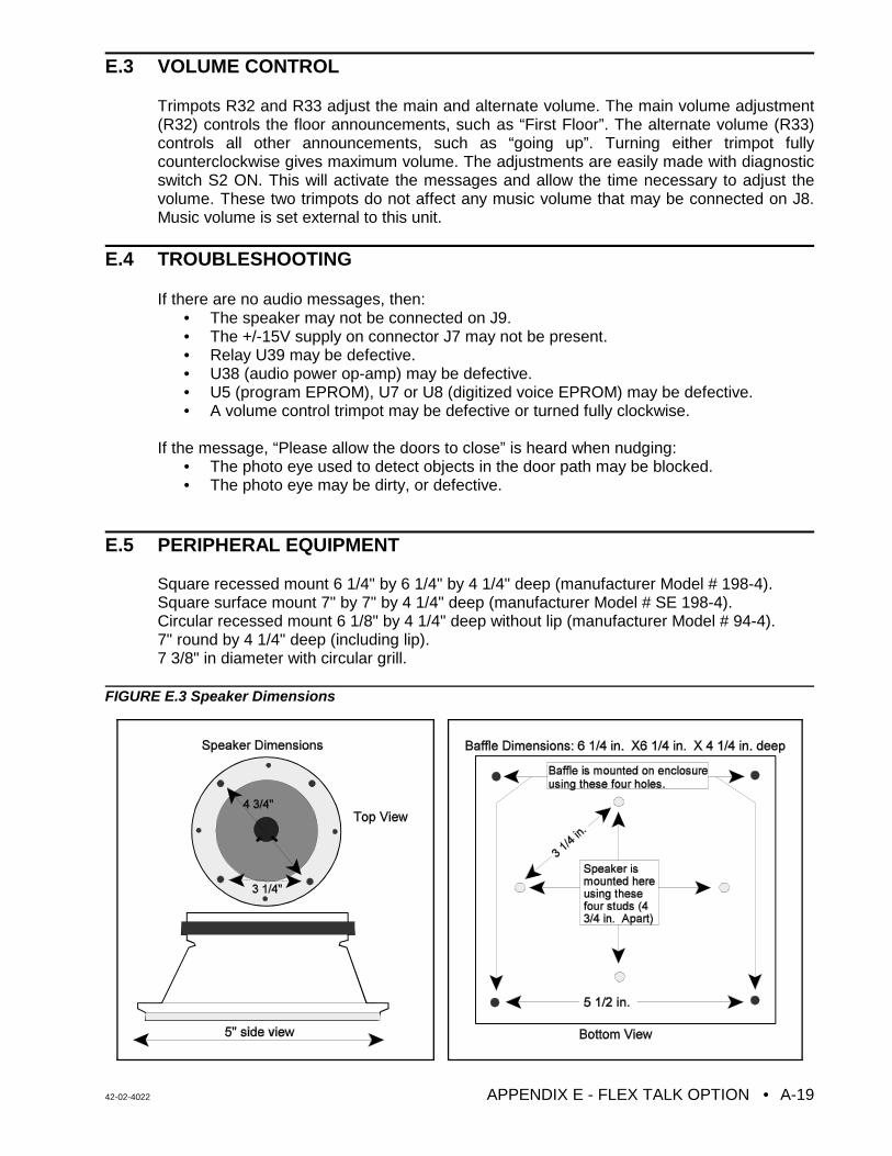
42-02-4022 APPENDIX E - FLEX TALK OPTION • A-19
E.3 VOLUME CONTROL
Trimpots R32 and R33 adjust the main and alternate volume. The main volume adjustment(R32) controls the floor announcements, such as “First Floor”. The alternate volume (R33)controls all other announcements, such as “going up”. Turning either trimpot fullycounterclockwise gives maximum volume. The adjustments are easily made with diagnosticswitch S2 ON. This will activate the messages and allow the time necessary to adjust thevolume. These two trimpots do not affect any music volume that may be connected on J8.Music volume is set external to this unit.
E.4 TROUBLESHOOTING
If there are no audio messages, then:• The speaker may not be connected on J9.• The +/-15V supply on connector J7 may not be present.• Relay U39 may be defective.
• U38 (audio power op-amp) may be defective.• U5 (program EPROM), U7 or U8 (digitized voice EPROM) may be defective.• A volume control trimpot may be defective or turned fully clockwise.
If the message, “Please allow the doors to close” is heard when nudging:• The photo eye used to detect objects in the door path may be blocked.• The photo eye may be dirty, or defective.
E.5 PERIPHERAL EQUIPMENT
Square recessed mount 6 1/4" by 6 1/4" by 4 1/4" deep (manufacturer Model # 198-4).Square surface mount 7" by 7" by 4 1/4" deep (manufacturer Model # SE 198-4).Circular recessed mount 6 1/8" by 4 1/4" deep without lip (manufacturer Model # 94-4).7" round by 4 1/4" deep (including lip).7 3/8" in diameter with circular grill.
FIGURE E.3 Speaker Dimensions
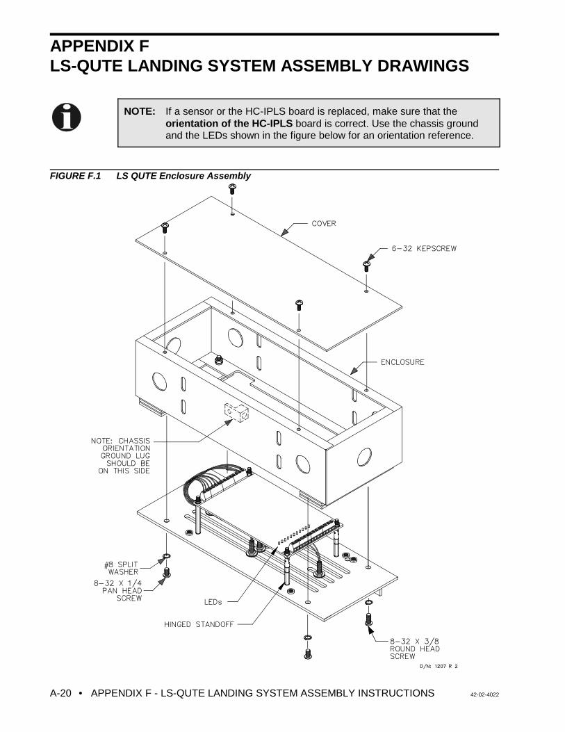
• APPENDIX F - LS-QUTE LANDING SYSTEM ASSEMBLY INSTRUCTIONS 42-02-4022A-20
APPENDIX FLS-QUTE LANDING SYSTEM ASSEMBLY DRAWINGS
FIGURE F.1 LS QUTE Enclosure Assembly
NOTE: If a sensor or the HC-IPLS board is replaced, make sure that theorientation of the HC-IPLS board is correct. Use the chassis groundand the LEDs shown in the figure below for an orientation reference.
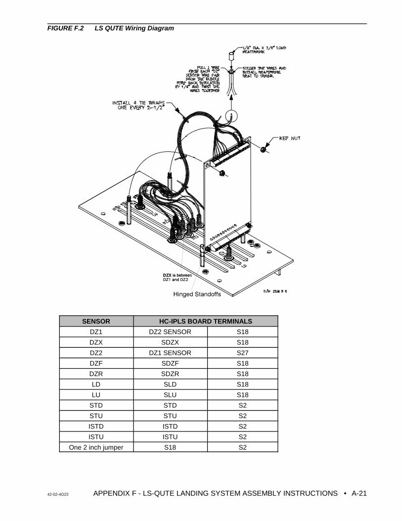
42-02-4O22 APPENDIX F - LS-QUTE LANDING SYSTEM ASSEMBLY INSTRUCTIONS • A-21
FIGURE F.2 LS QUTE Wiring Diagram
SENSOR HC-IPLS BOARD TERMINALS
DZ1 DZ2 SENSOR S18
DZX SDZX S18
DZ2 DZ1 SENSOR S27
DZF SDZF S18
DZR SDZR S18
LD SLD S18
LU SLU S18
STD STD S2
STU STU S2
ISTD ISTD S2
ISTU ISTU S2
One 2 inch jumper S18 S2
• APPENDIX G – SMARTLINK FOR CAR OPERATING PANEL 42-02-4022A-22
APPENDIX GOPTION SMARTLINK FOR CAR OPERATING PANEL
G.0 GENERAL INFORMATION
This Appendix applies to MCE Controllers with the following boards and software versions:MC-NC Software Version 2.00, and MC-NIO Software Version 2.00. SmartLINK SerialCommunication for Car Call Signals is an option for MCE controllers. It links the CarOperating Panel (COP) signals to the car controller in the machine room using serialcommunication techniques. This option reduces the wiring from the COP to the car controller;thus, reducing the installation time and labor cost. The serial link is based on state-of-the-artLonWorks® networking technology. A four-wire link carries the signals and power from theCOP to the car controller. If the SmartLINK for COP option is on this controller, reference thisAppendix Figure G.1 for controller and board layout. Otherwise, use the controller manualinformation only.
TABLE G.1 Principal Characteristics
PRINCIPAL CHARACTERISTICS
Number of Wires 4 (2 for data and 2 for power)
Power on serial link 24 VDC
Number of I/Os on one COP board 24 inputs, 24 outputs
Communication protocol LonTalk® (based on OSI 7-layer networking protocol)
Controller characteristics Available for M3 Group System car controllers
G.1 PRODUCT DESCRIPTION
SmartLINK Serial Communication for Car Call Signals provides a serial communication linkbetween the car controller and the Car Operating Panel (COP). Other than the input/outputinterface between the controller and the COP, there are no changes to the existing controller.The functionality of the controller is not affected.
G.1.1 CAR CONTROLLER NODE
The car controller node (MC-NC board) is the main node of the network. It provides theinput/output interface between the car controller computer (MC-MP2 board) and the COP. Itcontains the Neuron® processor which implements the seven layers of the LonTalk®
communication protocol for receiving and sending signals, as network data packets, to andfrom the COP. It also implements the application level routines to serially transfer these signalvalues to the car controller computer.
G.1.2 CAR OPERATING PANEL (COP) NODE
The function of the COP node (MC-NIO board) is to transfer COP signal values to and from thecar controller node as network packets. The COP signals, such as call buttons, door closebutton, call lockouts, etc., are sent serially to the car controller node via the LonWorks®
network. Similarly, signals such as call button lights, indicators, etc., are received from the carcontroller node.
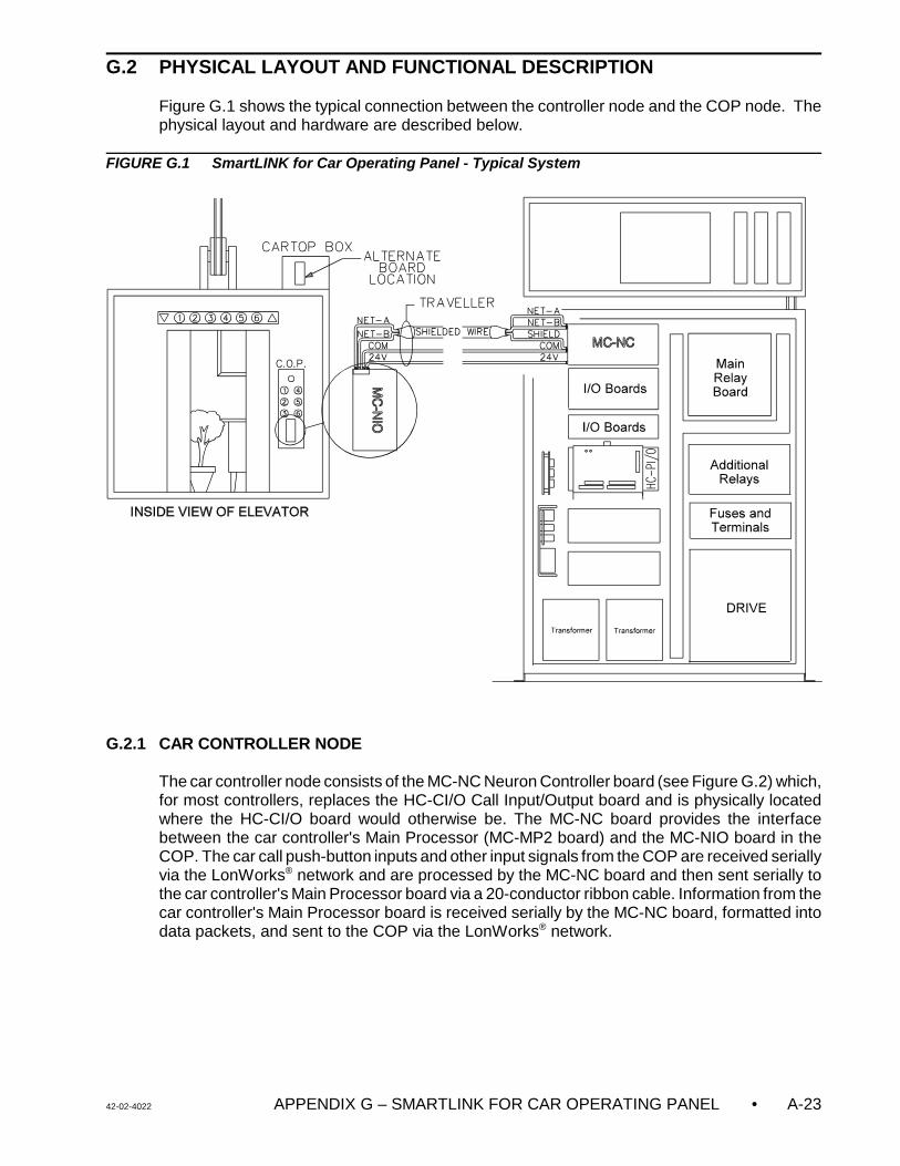
42-02-4022 APPENDIX G – SMARTLINK FOR CAR OPERATING PANEL • A-23
G.2 PHYSICAL LAYOUT AND FUNCTIONAL DESCRIPTION
Figure G.1 shows the typical connection between the controller node and the COP node. Thephysical layout and hardware are described below.
FIGURE G.1 SmartLINK for Car Operating Panel - Typical System
G.2.1 CAR CONTROLLER NODE
The car controller node consists of the MC-NC Neuron Controller board (see Figure G.2) which,for most controllers, replaces the HC-CI/O Call Input/Output board and is physically locatedwhere the HC-CI/O board would otherwise be. The MC-NC board provides the interfacebetween the car controller's Main Processor (MC-MP2 board) and the MC-NIO board in theCOP. The car call push-button inputs and other input signals from the COP are received seriallyvia the LonWorks® network and are processed by the MC-NC board and then sent serially tothe car controller's Main Processor board via a 20-conductor ribbon cable. Information from thecar controller's Main Processor board is received serially by the MC-NC board, formatted intodata packets, and sent to the COP via the LonWorks® network.
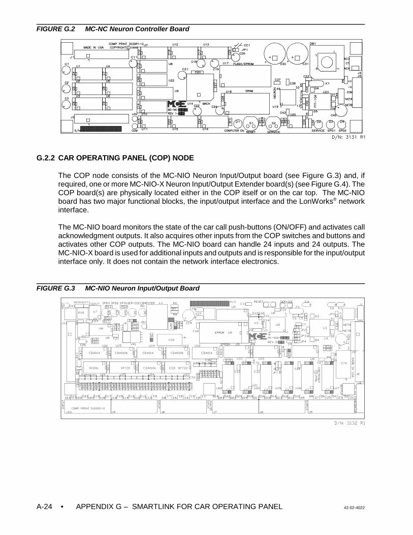
• APPENDIX G – SMARTLINK FOR CAR OPERATING PANEL 42-02-4022A-24
FIGURE G.2 MC-NC Neuron Controller Board
G.2.2 CAR OPERATING PANEL (COP) NODE
The COP node consists of the MC-NIO Neuron Input/Output board (see Figure G.3) and, ifrequired, one or more MC-NIO-X Neuron Input/Output Extender board(s) (see Figure G.4). TheCOP board(s) are physically located either in the COP itself or on the car top. The MC-NIOboard has two major functional blocks, the input/output interface and the LonWorks® networkinterface.
The MC-NIO board monitors the state of the car call push-buttons (ON/OFF) and activates callacknowledgment outputs. It also acquires other inputs from the COP switches and buttons andactivates other COP outputs. The MC-NIO board can handle 24 inputs and 24 outputs. TheMC-NIO-X board is used for additional inputs and outputs and is responsible for the input/outputinterface only. It does not contain the network interface electronics.
FIGURE G.3 MC-NIO Neuron Input/Output Board
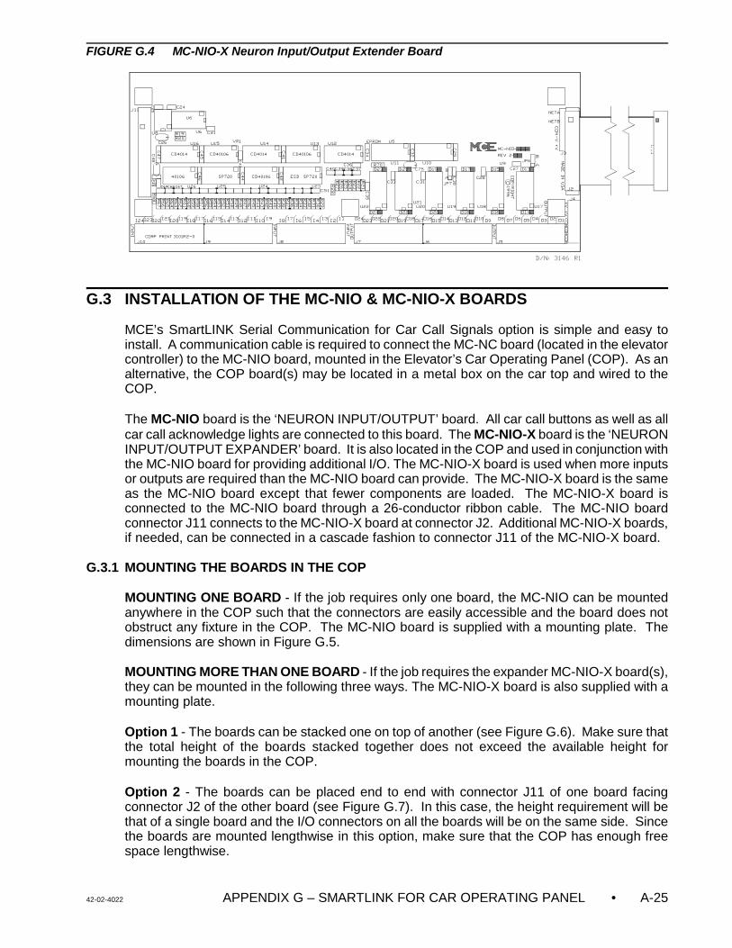
42-02-4022 APPENDIX G – SMARTLINK FOR CAR OPERATING PANEL • A-25
FIGURE G.4 MC-NIO-X Neuron Input/Output Extender Board
G.3 INSTALLATION OF THE MC-NIO & MC-NIO-X BOARDS
MCE’s SmartLINK Serial Communication for Car Call Signals option is simple and easy toinstall. A communication cable is required to connect the MC-NC board (located in the elevatorcontroller) to the MC-NIO board, mounted in the Elevator’s Car Operating Panel (COP). As analternative, the COP board(s) may be located in a metal box on the car top and wired to theCOP.
The MC-NIO board is the ‘NEURON INPUT/OUTPUT’ board. All car call buttons as well as allcar call acknowledge lights are connected to this board. The MC-NIO-X board is the ‘NEURONINPUT/OUTPUT EXPANDER’ board. It is also located in the COP and used in conjunction withthe MC-NIO board for providing additional I/O. The MC-NIO-X board is used when more inputsor outputs are required than the MC-NIO board can provide. The MC-NIO-X board is the sameas the MC-NIO board except that fewer components are loaded. The MC-NIO-X board isconnected to the MC-NIO board through a 26-conductor ribbon cable. The MC-NIO boardconnector J11 connects to the MC-NIO-X board at connector J2. Additional MC-NIO-X boards,if needed, can be connected in a cascade fashion to connector J11 of the MC-NIO-X board.
G.3.1 MOUNTING THE BOARDS IN THE COP
MOUNTING ONE BOARD - If the job requires only one board, the MC-NIO can be mountedanywhere in the COP such that the connectors are easily accessible and the board does notobstruct any fixture in the COP. The MC-NIO board is supplied with a mounting plate. Thedimensions are shown in Figure G.5.
MOUNTING MORE THAN ONE BOARD - If the job requires the expander MC-NIO-X board(s),they can be mounted in the following three ways. The MC-NIO-X board is also supplied with amounting plate.
Option 1 - The boards can be stacked one on top of another (see Figure G.6). Make sure thatthe total height of the boards stacked together does not exceed the available height formounting the boards in the COP.
Option 2 - The boards can be placed end to end with connector J11 of one board facingconnector J2 of the other board (see Figure G.7). In this case, the height requirement will bethat of a single board and the I/O connectors on all the boards will be on the same side. Sincethe boards are mounted lengthwise in this option, make sure that the COP has enough freespace lengthwise.
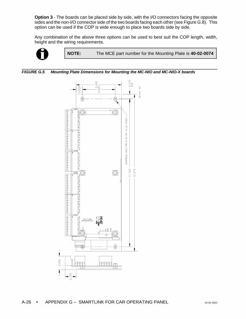
• APPENDIX G – SMARTLINK FOR CAR OPERATING PANEL 42-02-4022A-26
NOTE: The MCE part number for the Mounting Plate is 40-02-0074
Option 3 - The boards can be placed side by side, with the I/O connectors facing the oppositesides and the non-I/O connector side of the two boards facing each other (see Figure G.8). Thisoption can be used if the COP is wide enough to place two boards side by side.
Any combination of the above three options can be used to best suit the COP length, width,height and the wiring requirements.
FIGURE G.5 Mounting Plate Dimensions for Mounting the MC-NIO and MC-NIO-X boards
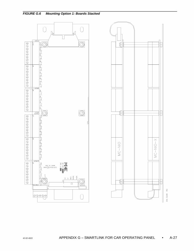
42-02-4022 APPENDIX G – SMARTLINK FOR CAR OPERATING PANEL • A-27
FIGURE G.6 Mounting Option 1: Boards Stacked
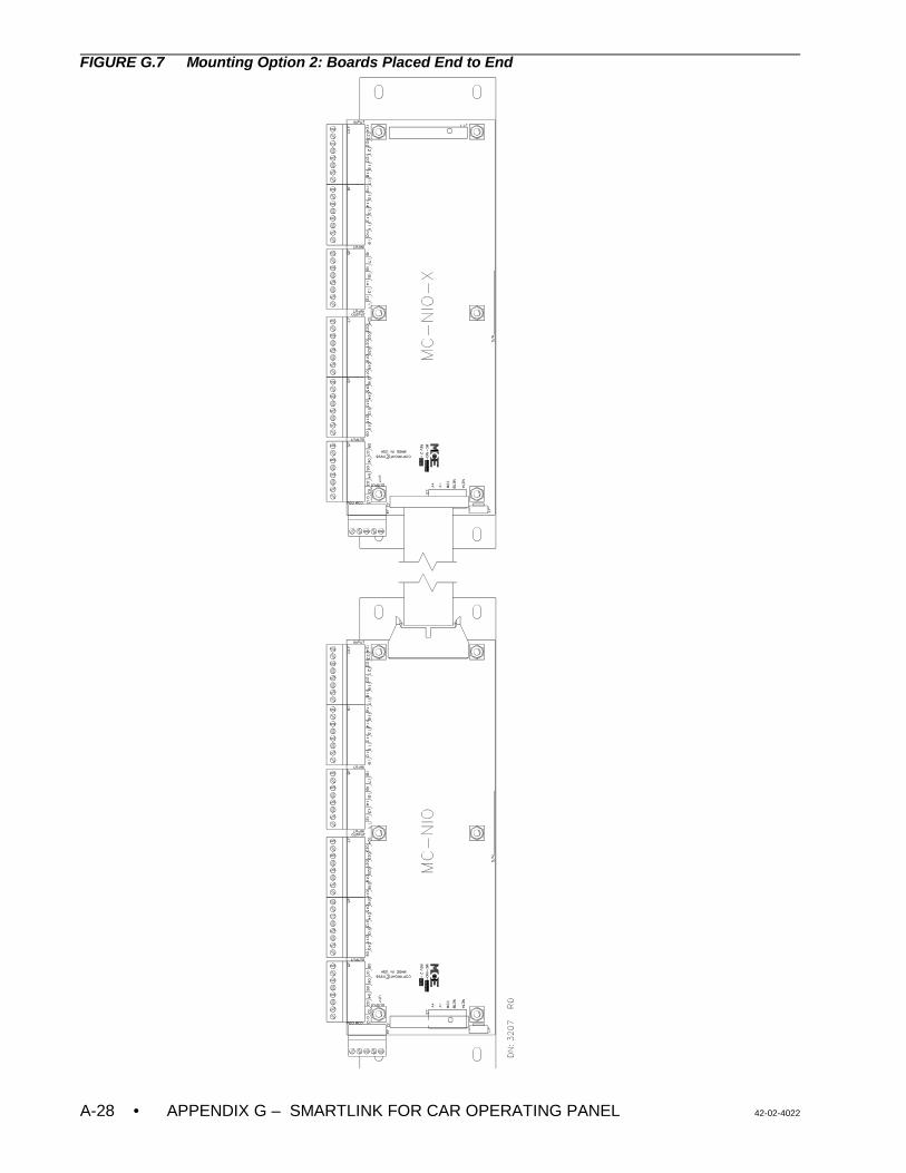
• APPENDIX G – SMARTLINK FOR CAR OPERATING PANEL 42-02-4022A-28
FIGURE G.7 Mounting Option 2: Boards Placed End to End
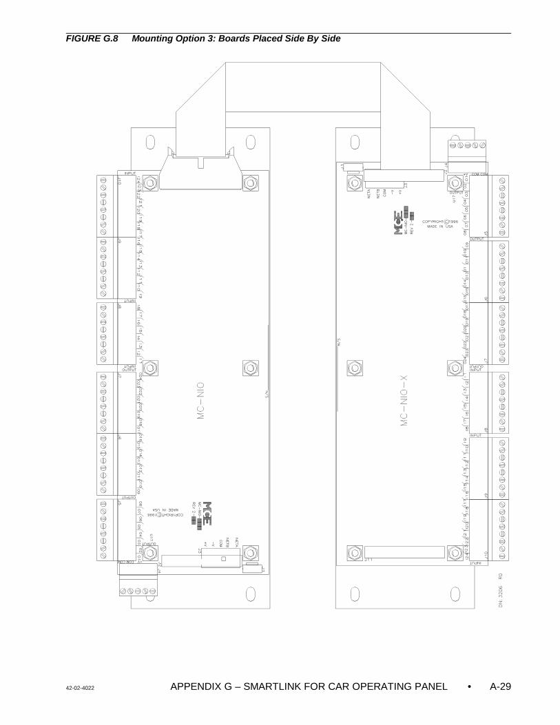
42-02-4022 APPENDIX G – SMARTLINK FOR CAR OPERATING PANEL • A-29
FIGURE G.8 Mounting Option 3: Boards Placed Side By Side
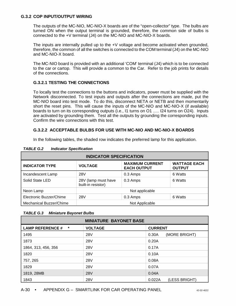
• APPENDIX G – SMARTLINK FOR CAR OPERATING PANEL 42-02-4022A-30
G.3.2 COP INPUT/OUTPUT WIRING
The outputs of the MC-NIO, MC-NIO-X boards are of the “open-collector” type. The bulbs areturned ON when the output terminal is grounded, therefore, the common side of bulbs isconnected to the +V terminal (J4) on the MC-NIO and MC-NIO-X boards.
The inputs are internally pulled up to the +V voltage and become activated when grounded,therefore, the common of all the switches is connected to the COM terminal (J4) on the MC-NIOand MC-NIO-X board.
The MC-NIO board is provided with an additional ‘COM’ terminal (J4) which is to be connectedto the car or cartop. This will provide a common to the Car. Refer to the job prints for detailsof the connections.
G.3.2.1 TESTING THE CONNECTIONS
To locally test the connections to the buttons and indicators, power must be supplied with theNetwork disconnected. To test inputs and outputs after the connections are made, put theMC-NIO board into test mode. To do this, disconnect NETA or NETB and then momentarilyshort the reset pins. This will cause the inputs of the MC-NIO and MC-NIO-X (if available)boards to turn on its corresponding outputs (i.e., I1 turns on O1 ..... I24 turns on O24). Inputsare activated by grounding them. Test all the outputs by grounding the corresponding inputs.Confirm the wire connections with this test.
G.3.2.2 ACCEPTABLE BULBS FOR USE WITH MC-NIO AND MC-NIO-X BOARDS
In the following tables, the shaded row indicates the preferred lamp for this application.
TABLE G.2 Indicator Specification
INDICATOR SPECIFICATION
INDICATOR TYPE VOLTAGE MAXIMUM CURRENTEACH OUTPUT
WATTAGE EACHOUTPUT
Incandescent Lamp 28V 0.3 Amps 6 Watts
Solid State LED 28V (lamp must havebuilt-in resistor)
0.3 Amps 6 Watts
Neon Lamp Not applicable
Electronic Buzzer/Chime 28V 0.3 Amps 6 Watts
Mechanical Buzzer/Chime Not Applicable
TABLE G.3 Miniature Bayonet Bulbs
MINIATURE BAYONET BASE
LAMP REFERENCE # * VOLTAGE CURRENT
1495 28V 0.30A (MORE BRIGHT)
1873 28V 0.20A
1864, 313, 456, 356 28V 0.17A
1820 28V 0.10A
757, 265 28V 0.08A
1829 28V 0.07A
1819, 28MB 28V 0.04A
1843 28V 0.022A (LESS BRIGHT)
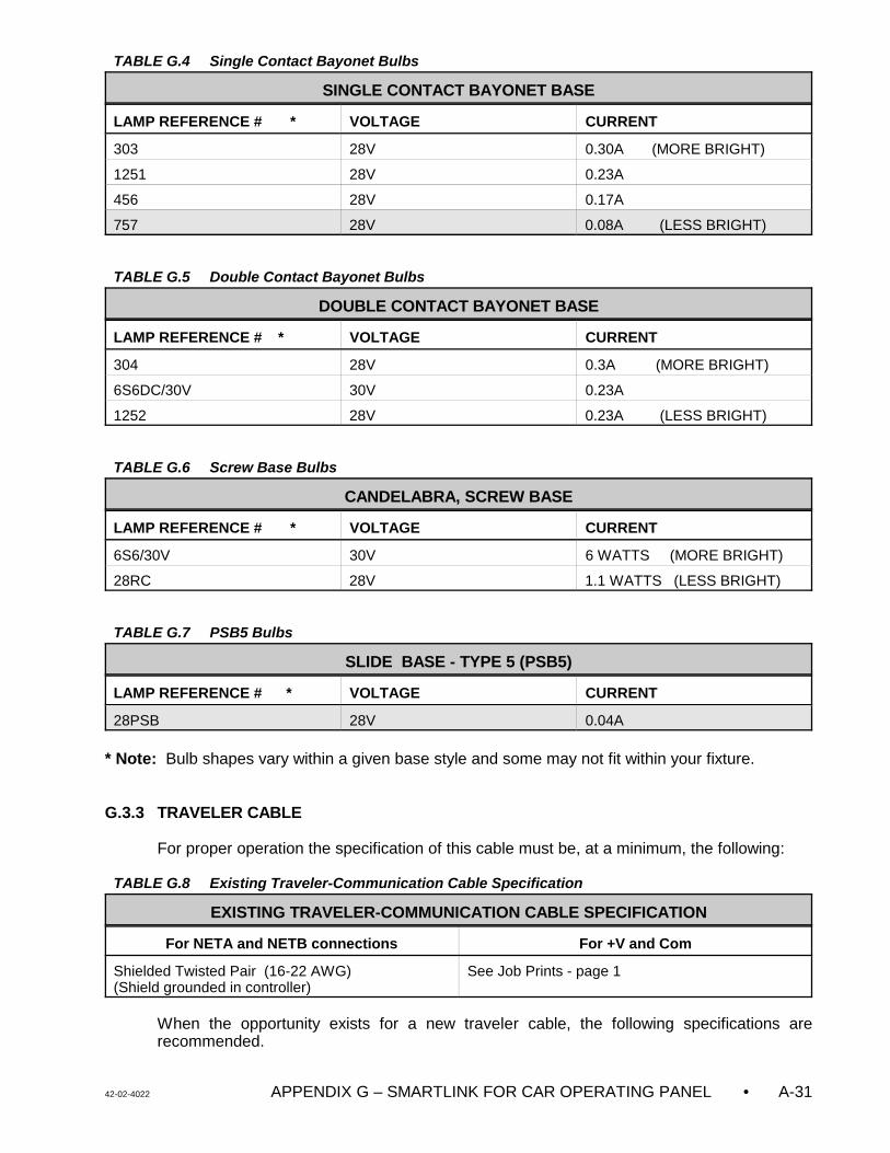
42-02-4022 APPENDIX G – SMARTLINK FOR CAR OPERATING PANEL • A-31
TABLE G.4 Single Contact Bayonet Bulbs
SINGLE CONTACT BAYONET BASE
LAMP REFERENCE # * VOLTAGE CURRENT
303 28V 0.30A (MORE BRIGHT)
1251 28V 0.23A
456 28V 0.17A
757 28V 0.08A (LESS BRIGHT)
TABLE G.5 Double Contact Bayonet Bulbs
DOUBLE CONTACT BAYONET BASE
LAMP REFERENCE # * VOLTAGE CURRENT
304 28V 0.3A (MORE BRIGHT)
6S6DC/30V 30V 0.23A
1252 28V 0.23A (LESS BRIGHT)
TABLE G.6 Screw Base Bulbs
CANDELABRA, SCREW BASE
LAMP REFERENCE # * VOLTAGE CURRENT
6S6/30V 30V 6 WATTS (MORE BRIGHT)
28RC 28V 1.1 WATTS (LESS BRIGHT)
TABLE G.7 PSB5 Bulbs
SLIDE BASE - TYPE 5 (PSB5)
LAMP REFERENCE # * VOLTAGE CURRENT
28PSB 28V 0.04A
* Note: Bulb shapes vary within a given base style and some may not fit within your fixture.
G.3.3 TRAVELER CABLE
For proper operation the specification of this cable must be, at a minimum, the following:
TABLE G.8 Existing Traveler-Communication Cable Specification
EXISTING TRAVELER-COMMUNICATION CABLE SPECIFICATION
For NETA and NETB connections For +V and Com
Shielded Twisted Pair (16-22 AWG) (Shield grounded in controller)
See Job Prints - page 1
When the opportunity exists for a new traveler cable, the following specifications arerecommended.
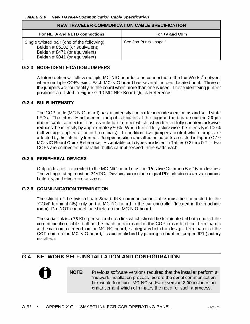
• APPENDIX G – SMARTLINK FOR CAR OPERATING PANEL 42-02-4022A-32
TABLE G.9 New Traveler-Communication Cable Specification
NEW TRAVELER-COMMUNICATION CABLE SPECIFICATION
For NETA and NETB connections For +V and Com
Single twisted pair (one of the following)Belden # 85102 (or equivalent)Belden # 8471 (or equivalent)Belden # 9841 (or equivalent)
See Job Prints - page 1
G.3.3 NODE IDENTIFICATION JUMPERS
A future option will allow multiple MC-NIO boards to be connected to the LonWorks® networkwhere multiple COPs exist. Each MC-NIO board has several jumpers located on it. Three ofthe jumpers are for identifying the board when more than one is used. These identifying jumperpositions are listed in Figure G.10 MC-NIO Board Quick Reference.
G.3.4 BULB INTENSITY
The COP node (MC-NIO board) has an intensity control for incandescent bulbs and solid stateLEDs. The intensity adjustment trimpot is located at the edge of the board near the 26-pinribbon cable connector. It is a single turn trimpot which, when turned fully counterclockwise,reduces the intensity by approximately 50%. When turned fully clockwise the intensity is 100%(full voltage applied at output terminals). In addition, two jumpers control which lamps areaffected by the intensity trimpot. Jumper position and affected outputs are listed in Figure G.10MC-NIO Board Quick Reference. Acceptable bulb types are listed in Tables 0.2 thru 0.7. If twoCOPs are connected in parallel, bulbs cannot exceed three watts each.
G.3.5 PERIPHERAL DEVICES
Output devices connected to the MC-NIO board must be “Positive Common Bus” type devices.The voltage rating must be 24VDC. Devices can include digital PI’s, electronic arrival chimes,lanterns, and electronic buzzers.
G.3.6 COMMUNICATION TERMINATION
The shield of the twisted pair SmartLINK communication cable must be connected to the“COM” terminal (J5) only on the MC-NC board in the car controller (located in the machineroom). Do NOT connect the shield on the MC-NIO board.
The serial link is a 78 Kbit per second data link which should be terminated at both ends of thecommunication cable, both in the machine room and in the COP or car top box. Terminationat the car controller end, on the MC-NC board, is integrated into the design. Termination at theCOP end, on the MC-NIO board, is accomplished by placing a shunt on jumper JP1 (factoryinstalled).
G.4 NETWORK SELF-INSTALLATION AND CONFIGURATION
NOTE: Previous software versions required that the installer perform a“network installation process” before the serial communicationlink would function. MC-NC software version 2.00 includes anenhancement which eliminates the need for such a process.
42-02-4022 APPENDIX G – SMARTLINK FOR CAR OPERATING PANEL • A-33
After all electrical connections have been made, network communication should be establishedapproximately 10 seconds after system power-up.
G.4.1 NETWORK COMMUNICATION
The diagnostic LED SPD2 on the MC-NC board indicates network activity/status.
If the SPD2 LED on the MC-NC board blinks at an approximate rate of twice per second,network communication has been established.
If the LED is solidly ON or OFF, the network communication is not established. Check thenetwork wire connections to NETA and NETB.
Diagnostic address 3017H contains a communication error counter. Normally all diagnosticLEDs displayed at this address should be OFF on the computer swing panel. If the countersare increasing rapidly (once every 10 seconds), the communication is not stable, check forproper wiring and shielding.
G.5 TROUBLESHOOTING GENERAL
The Diagnostic Indicators on the MC-NC and MC-NIO boards and on the Computer SwingPanel assist in troubleshooting the SmartLINK Serial Communication for Car Call Signals. TheSmartLINK for Car Calls option requires two additional boards, the MC-NC Neuron Controllerboard (in the car controller) and MC-NIO, Neuron Input/Output board (in the COP or on top ofthe car). Both of these boards have a processor on them and run independent softwareprograms.
G.5.1 TROUBLESHOOTING THE MC-NC BOARD
Begin by examining the indicators and jumpers on the MC-NC board (see Figure G.9, MC-NCQuick Reference).
G.5.1.1 COMPUTER ON LED
Upon power-up the “Computer On” LED on the MC-NC board should be solidly ON. If this LEDis OFF or blinking, verify that the EPROM is installed properly and that all the ribbon cableconnections are secure. Verify that the voltage at the +5V test point (located near ribbon cableconnector J2) is between 4.75V and 5.1V.
G.5.1.2 COMMUNICATION WITH THE MAIN COMPUTER
The diagnostic LED SPD1 on the MC-NC board indicates communication activity with the Maincomputer (MC-MP2). If this LED is solidly ON, it means that the MC-NC and the MainComputer are not communicating. Verify that the ribbon cable is connected properly to J2.Proper communication is indicated by the SPD1 LED blinking at a rate of approximately 20times/second.
G.5.1.3 NETWORK COMMUNICATION
The network communication status is indicated by diagnostic LED SPD2 on the MC-NC board.If this LED is solidly ON, it means that the network communication is not established. Verify thatthe network wires are connected properly to NETA and NETB on the connector.
To confirm that the network communication is established properly, check the SPD2 LED onthe MC-NC board. It should be blinking at a rate of twice a second. If the SPD2 LED on the
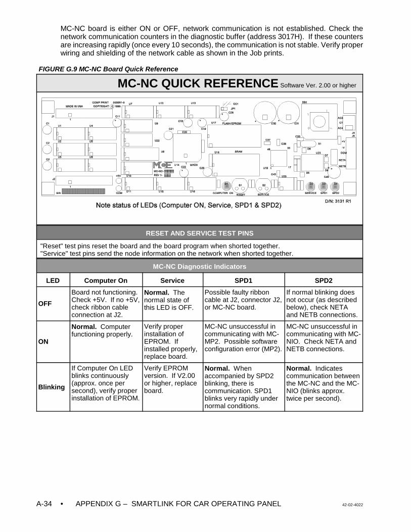
• APPENDIX G – SMARTLINK FOR CAR OPERATING PANEL 42-02-4022A-34
MC-NC board is either ON or OFF, network communication is not established. Check thenetwork communication counters in the diagnostic buffer (address 3017H). If these countersare increasing rapidly (once every 10 seconds), the communication is not stable. Verify properwiring and shielding of the network cable as shown in the Job prints.
FIGURE G.9 MC-NC Board Quick Reference
MC-NC QUICK REFERENCE Software Ver. 2.00 or higher
RESET AND SERVICE TEST PINS
"Reset" test pins reset the board and the board program when shorted together."Service" test pins send the node information on the network when shorted together.
MC-NC Diagnostic Indicators
LED Computer On Service SPD1 SPD2
OFF
Board not functioning. Check +5V. If no +5V,check ribbon cableconnection at J2.
Normal. Thenormal state ofthis LED is OFF.
Possible faulty ribboncable at J2, connector J2,or MC-NC board.
If normal blinking doesnot occur (as describedbelow), check NETAand NETB connections.
ON
Normal. Computerfunctioning properly.
Verify properinstallation ofEPROM. Ifinstalled properly,replace board.
MC-NC unsuccessful incommunicating with MC-MP2. Possible softwareconfiguration error (MP2).
MC-NC unsuccessful incommunicating with MC-NIO. Check NETA andNETB connections.
Blinking
If Computer On LEDblinks continuously(approx. once persecond), verify properinstallation of EPROM.
Verify EPROMversion. If V2.00or higher, replaceboard.
Normal. Whenaccompanied by SPD2blinking, there iscommunication. SPD1blinks very rapidly undernormal conditions.
Normal. Indicatescommunication betweenthe MC-NC and the MC-NIO (blinks approx.twice per second).
42-02-4022 APPENDIX G – SMARTLINK FOR CAR OPERATING PANEL • A-35
G.5.2 TROUBLESHOOTING THE MC-NIO BOARD
Begin by examining the indicators and jumpers on the MC-NIO board (see Figure G.10, MC-NIO Quick Reference).
G.5.2.1 COMPUTER ON LED
Upon power-up the “Computer ON” LED on the MC-NIO board should be solidly ON. If the LEDis OFF or is flashing, verify that the EPROM is installed properly and the voltage on the +V pinof connector J3 is between 12V and 28V and that the voltage at the +5V test point is between4.75 and 5.15V.
G.5.2.2 NETWORK COMMUNICATION
The network communication status is indicated by diagnostic LED SPD2 on both the MC-NCand the MC-NIO boards. If this LED is solidly ON, it means that the network communicationis not established (see the diagnostic indicator table on the MC-NIO QR card).
G.5.2.3 BULB INTENSITY CONTROL
If the bulbs do not come on or if varying the intensity trimpot has no effect on the bulb intensitycheck jumpers JP6 and JP7 (see Figure G.10, MC-NIO Quick Reference ). If the jumpers areinstalled correctly and the bulb intensity still does not work, replace the MC-NIO board.
G.5.2.4 MC-NIO & MC-NIO-X OUTPUTS
Testing During Installation - To test inputs and outputs during installation, put the MC-NIOboard into test mode. To do this, ensure that the board has power at the +V to COM terminalsat connector J3, then disconnect the NETA wire and momentarily short the reset pins. This willcause the inputs of the MC-NIO and MC-NIO-X (if available) boards to turn ON itscorresponding outputs (i.e., I1 turns on O1 ..... I24 turns on O24). Inputs are activated bygrounding them. Test all the outputs.
Output Fails During Operation - If a previously working output fails, check the output deviceand wiring. If the device is functional, and the wiring correct, swap the corresponding driverchip with another driver chip (U17 to U22) to check for a failed driver. If problem remains,replace the board.
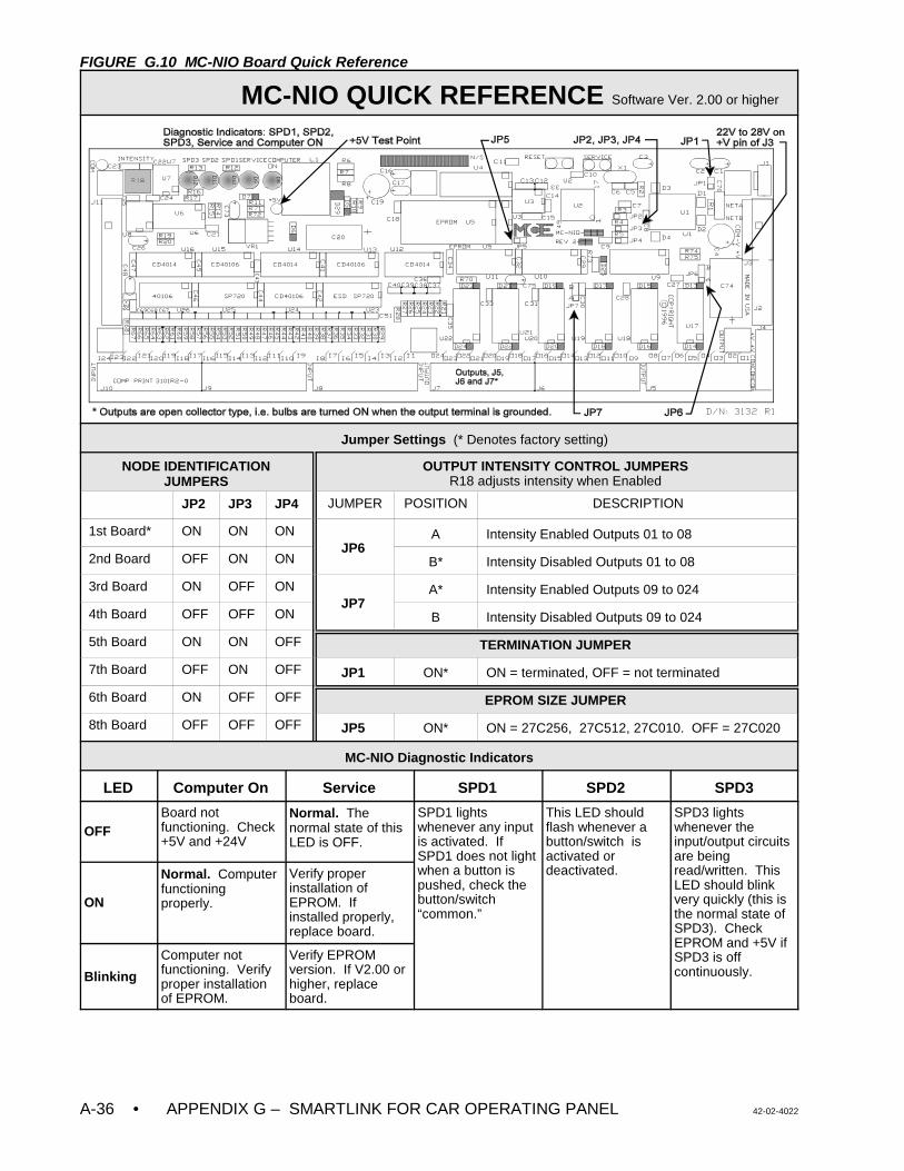
• APPENDIX G – SMARTLINK FOR CAR OPERATING PANEL 42-02-4022A-36
FIGURE G.10 MC-NIO Board Quick Reference
MC-NIO QUICK REFERENCE Software Ver. 2.00 or higher
Jumper Settings (* Denotes factory setting)
NODE IDENTIFICATIONJUMPERS
OUTPUT INTENSITY CONTROL JUMPERSR18 adjusts intensity when Enabled
JP2 JP3 JP4 JUMPER POSITION DESCRIPTION
1st Board* ON ON ONJP6
A Intensity Enabled Outputs 01 to 08
2nd Board OFF ON ON B* Intensity Disabled Outputs 01 to 08
3rd Board ON OFF ONJP7
A* Intensity Enabled Outputs 09 to 024
4th Board OFF OFF ON B Intensity Disabled Outputs 09 to 024
5th Board ON ON OFF TERMINATION JUMPER
7th Board OFF ON OFF JP1 ON* ON = terminated, OFF = not terminated
6th Board ON OFF OFF EPROM SIZE JUMPER
8th Board OFF OFF OFF JP5 ON* ON = 27C256, 27C512, 27C010. OFF = 27C020
MC-NIO Diagnostic Indicators
LED Computer On Service SPD1 SPD2 SPD3
OFFBoard notfunctioning. Check+5V and +24V
Normal. Thenormal state of thisLED is OFF.
SPD1 lightswhenever any inputis activated. IfSPD1 does not lightwhen a button ispushed, check thebutton/switch“common.”
This LED shouldflash whenever abutton/switch isactivated ordeactivated.
SPD3 lightswhenever theinput/output circuitsare beingread/written. ThisLED should blinkvery quickly (this isthe normal state ofSPD3). CheckEPROM and +5V ifSPD3 is offcontinuously.
ON
Normal. Computerfunctioningproperly.
Verify properinstallation ofEPROM. Ifinstalled properly,replace board.
Blinking
Computer notfunctioning. Verifyproper installationof EPROM.
Verify EPROMversion. If V2.00 orhigher, replaceboard.
42-02-4022 APPENDIX G – SMARTLINK FOR CAR OPERATING PANEL • A-37
G.5.3 SYSTEM TROUBLESHOOTING
GENERAL The serial link is a method of transferring input status (buttons and switches) andoutput status (indicators) between the car operating panel and the elevator controller. A non-operational serial link would generally result in the complete failure in the transfer of thisinformation. When troubleshooting a problem that you believe might be attributed to a failureof the serial link, bear in mind that the serial link is simply an I/O system. For example, theinability to register a car call from the car operating panel may be due to reasons other than theserial link. Whenever possible, separate the issues (divide and conquer) through creativemeans (e.g., try to register car calls via the group or local CRT to determine if car calls can beregistered at all).
A few examples are given below, with commentaries that serve to illustrate the conceptsdiscussed above.
Problem: Car call buttons do not illuminate when pressed, and the calls do not latch.
Pushing a car call button should always result in the illumination of the indicator for that button.If the car call indicators do not light when the respective buttons are pushed, a failure of theserial link should be investigated. Special attention should be paid to the serial bus wiring (thewires that make up the serial link), especially when this behavior applies to all of the car callbuttons (not just a select few). Follow the instructions in the “General Troubleshooting Steps”section below.
Problem: Car calls do latch, and a number of car calls can be registered, but after awhile all thecalls cancel simultaneously. The car stops at the next landing and does not open its doors.
Because the car calls can, in fact, be registered through the car operating panel, and becausethe car call indicators do function properly, the problem described may not be related to theserial link. Cancellation of the car calls may be a result of something unrelated to the serial link(e.g., anti-nuisance logic), so it is important to keep an open mind (don’t assume that the seriallink is the cause for canceling the car calls). Check the job prints for inputs that are beingtransferred through the serial link. There may be an input transferred through the serial linkthat may cause car cancellation should an intermittent problem with the input signal exist. Forexample, “flickering” of the independent service input will generally result in car call cancellation(it is typical to initially cancel all car calls whenever an off-to-on transition of independentservice is detected).
Problem: When pressed, the call buttons illuminate, but then extinguish. The call does notlatch.
Discussion: This may or may not be a problem with the serial link. During conditions in whichcar calls are not allowed to latch by the controller main processor, this behavior is expected.Follow the “General Troubleshooting Steps” outlined below.
GENERAL TROUBLESHOOTING STEPS
Step 1 Determine if car calls can, in fact, be registered. On many products this can beaccomplished via a system CRT Terminal (connected to either the elevator controlleror a Group Supervisor). If a CRT is not available, car calls can be latched via theelevator controller’s swing panel. Section 5 of the controller’s installation manual
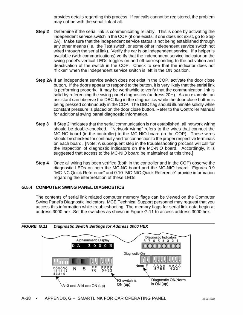
• APPENDIX G – SMARTLINK FOR CAR OPERATING PANEL 42-02-4022A-38
provides details regarding this process. If car calls cannot be registered, the problemmay not be with the serial link at all.
Step 2 Determine if the serial link is communicating reliably. This is done by activating theindependent service switch in the COP (if one exists; if one does not exist, go to Step2A). Make sure that the independent service status is not being established throughany other means (i.e., the Test switch, or some other independent service switch notwired through the serial link). Verify the car is on independent service. If a helper isavailable (with communications) verify that the independent service indicator on theswing panel’s vertical LEDs toggles on and off corresponding to the activation anddeactivation of the switch in the COP. Check to see that the indicator does not“flicker” when the independent service switch is left in the ON position.
Step 2A If an independent service switch does not exist in the COP, activate the door closebutton. If the doors appear to respond to the button, it is very likely that the serial linkis performing properly. It may be worthwhile to verify that the communication link issolid by referencing the swing panel diagnostics (address 20H). As an example, anassistant can observe the DBC flag in the diagnostics while the door close button isbeing pressed continuously in the COP. The DBC flag should illuminate solidly whileconstant pressure is placed on the door close button. Refer to the Controller Manualfor additional swing panel diagnostic information.
Step 3 If Step 2 indicates that the serial communication is not established, all network wiringshould be double-checked. “Network wiring” refers to the wires that connect theMC-NC board (in the controller) to the MC-NIO board (in the COP). These wiresshould be checked for continuity and for connection to the proper respective terminalson each board. [Note: A subsequent step in the troubleshooting process will call forthe inspection of diagnostic indicators on the MC-NIO board. Accordingly, it issuggested that access to the MC-NIO board be maintained at this time.]
Step 4 Once all wiring has been verified (both in the controller and in the COP) observe thediagnostic LEDs on both the MC-NC board and the MC-NIO board. Figures 0.9“MC-NC Quick Reference” and 0.10 “MC-NIO Quick Reference” provide informationregarding the interpretation of these LEDs.
G.5.4 COMPUTER SWING PANEL DIAGNOSTICS
The contents of serial link related computer memory flags can be viewed on the ComputerSwing Panel's Diagnostic Indicators. MCE Technical Support personnel may request that youaccess this information while troubleshooting. The memory flags for serial link data begin ataddress 3000 hex. Set the switches as shown in Figure G.11 to access address 3000 hex.
FIGURE G.11 Diagnostic Switch Settings for Address 3000 HEX
42-02-4022 APPENDIX G – SMARTLINK FOR CAR OPERATING PANEL • A-39
Switches A13 and A14 select the first two digits of the address (30) with A9 thru A12 OFF(down) and A13 and A14 ON (up). Switches A1 thru A8 select the last two digits of the address(00) with A1 thru A8 OFF (down). The Alphanumeric Display indicates that address 3000 hexis selected (DA.3000H). The Diagnostic Indicators show the status of the computer memoryflags at this location (LED ON = 1, LED OFF = 0).
Software Version Verification for the MC-NC: Address 03000H displays the major versionnumber on the diagnostic indicators. Address 03001H displays the minor version number. Seeexample below.
Example:
Car call inputs from the MC-NC board to the MC-MP2 board, and car call latched outputs fromthe MC-MP2 board may be viewed in the following addresses and are useful troubleshootingtools.
TABLE G.10 Key Diagnostic Memory Addresses
Alpha-numericDisplay
Switch SettingA14 - A9 A8 - A1
Diagnostic Indicators LED Designation
3017H Displays the count of failedattempts for MC-NCcommunication.
LEDs should be OFF.
3040H Displays the car call inputsfrom the MC-NIO board.
LEDs correspond to the first eightfloors. Subsequent floor calls areviewed at address 3041, 3042 etc.
3080H Displays the car callregistration outputs fromthe Main controller.
LEDs correspond to the first eightfloors. Subsequent floor calls areviewed at address 3081, 3082 etc.
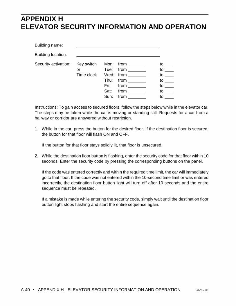
• APPENDIX H - ELEVATOR SECURITY INFORMATION AND OPERATION 42-02-4022A-40
APPENDIX HELEVATOR SECURITY INFORMATION AND OPERATION
Building name:
Building location:
Security activation: Key switch Mon: from to or Tue: from to
Time clock Wed: from to Thu: from to Fri: from to Sat: from to Sun: from to
Instructions: To gain access to secured floors, follow the steps below while in the elevator car.The steps may be taken while the car is moving or standing still. Requests for a car from ahallway or corridor are answered without restriction.
1. While in the car, press the button for the desired floor. If the destination floor is secured,the button for that floor will flash ON and OFF.
If the button for that floor stays solidly lit, that floor is unsecured.
2. While the destination floor button is flashing, enter the security code for that floor within 10seconds. Enter the security code by pressing the corresponding buttons on the panel.
If the code was entered correctly and within the required time limit, the car will immediatelygo to that floor. If the code was not entered within the 10-second time limit or was enteredincorrectly, the destination floor button light will turn off after 10 seconds and the entiresequence must be repeated.
If a mistake is made while entering the security code, simply wait until the destination floorbutton light stops flashing and start the entire sequence again.

42-02-4022 APPENDIX H - ELEVATOR SECURITY INFORMATION AND OPERATION • A-41
SECURITY CODES
Maintain a record of the security codes by noting the floor name as found in the elevator caband each floor's code. Any floor with a security code is a secured floor.
1. Floor security code =
2. Floor security code =
3. Floor security code =
4. Floor security code =
5. Floor security code =
6. Floor security code =
7. Floor security code =
8. Floor security code =
9. Floor security code =
10. Floor security code =
11. Floor security code =
12. Floor security code =
13. Floor security code =
14. Floor security code =
15. Floor security code =
16. Floor security code =
17. Floor security code =
18. Floor security code =
19. Floor security code =
20. Floor security code =
21. Floor security code =
22. Floor security code =
23. Floor security code =
24. Floor security code =
25. Floor security code =
26. Floor security code =
27. Floor security code =
28. Floor security code =
29. Floor security code =
30. Floor security code =
31. Floor security code =
32. Floor security code =
42-02-4022 INDEX • I-1
INDEX
2BI Redundancy Fault message, 6-212ND LANDING AUX. ACCESS FAULT message, 6-4, 6-94 BUS Cycle Test Fault message, 6-21
Aabsolute floor encoding, 4-2ACCI Redundancy Fault message, 6-21AFR2, Second Alternate Fire Floor Recall, 5-17AFT, Alternate Fire Floor Recall, 5-17Alarm - No Car Movement message, 6-9Alarm - No Door Zone message, 6-9AlmNoDZ, car operation message, 6-8, 6-9AlmNoMv, car operation message, 6-8, 6-9alphanumeric display, Swing Panel, 5-2
viewing the MP flags, 5-9AltFir1, car operation message, 6-8, 6-13Anti-Nuisance Operation message, 6-9AntiNui, car operation message, 6-8, 6-9APP1, Alternate Primary (lower) Parking Floor, 5-17APP2, Alternate Primary (lower) Parking Floor #2, 5-17Armature Voltage, 4-11AS OR ASPR RELAYS DROPPING, 6-71ASME A17.1 - 2000 Code
Ascending Car Overspeed Protection, 4-19Compliant Functions and Testing, 4-18Fault Troubleshooting Tables, 6-87-89Overspeed Calibration and Testing, 4-18Redundancy Fault Data Trap, 6-87SC-HDIO Board Input / Output Map, 6-89SC-HDIO Board Input Data Trap, 6-88SC-HDIO Board Input Map, Raw, 6-89Unintended Car Movement Protection, 4-19
ASP1, Alternate Secondary (upper) Parking Floor, 5-17ASP2, Alternate Secondary (upper) Parking Floor #2, 5-17ASPR RELAY DROPPING, 6-71Attendant Service Operation, 6-9ATTENDANT SERVICE OPERATION message, 6-4, 6-9AttnSrv, car operation message, 6-8, 6-9Automatic Operation, 6-9AutoOps, car operation message, 6-8, 6-9AUX. INSPECTION ACCESS FAULT message, 6-4, 6-9
BBDD trimpot, 3-14, 4-1, 4-11BDD, Brake Drop Delay trimpot, 6-66BflrDem, car operation message, 6-8, 6-9BOTH LEVELING SWITCHES ARE ON (SETUP ERROR),
LEARN MODE message, 6-4Both USD and DSD Are Open message, 6-9BOTH USD AND DSD INPUTS ARE ACTIVE message, 6-4Bottom Floor Demand message, 6-9
F3 screen (BflrDem), 6-8BOTTOM FLOOR OR TOP FLOOR DEMAND message, 6-4, 6-
19BOTTOM LANDING AUX. ACCESS FAULT message, 6-4, 6-9brake adjustments, 4-8Brake Drop Delay, 4-1, 4-11Brake Operation Sequence, 6-73BRAKE PICK FAILURE message, 6-4, 6-9brake switch, installation of, 2-10buffer tests, 4-15Byp-HLW, car operation message, 6-8, 6-14
Ccall circuits, troubleshooting, 6-57call logic, troubleshooting, 6-54, 6-56, 6-57Car Call Bus Fuse Blown message, 6-10CAR CALL BUS IS DISCONNECTED message, 6-4, 6-10car calls, registering, 4-2Car Communication Control (CCC)
MC-CGP-4(8) Board Quick Reference, 6-60MC-RS Board Quick Reference, 6-61
Car Communications Control (COC)components, 1-15
CAR IN TEST MODE message, 6-4, 6-18Car is Overloaded message, 6-10Car Network ID, setting, 4-20CAR NOT AT BOTTOM LANDING (SETUP ERROR), LEARN
MODE message, 6-4CAR NOT BELOW DOOR ZONE (SETUP ERROR), LEARN
MODE message, 6-4CAR NOT ON INSPECTION (SETUP ERROR), LEARN MODE
message, 6-4CAR NOT ON LEVEL DOWN (SETUP ERROR), LEARN MODE
message, 6-4CAR NOT ON LEVEL UP (SETUP ERROR), LEARN MODE
message, 6-4Car Operation Control (COC)
call logic troubleshooting, 6-54, 6-56, 6-57components, 1-7, 1-8, 1-12door logic troubleshooting, 6-47HC-CI/O Board Quick Reference, 6-56inputs and outputs, 1-13, 1-14MC-MP2 Board Quick Reference, 6-59troubleshooting, tracing signals, 6-48, 6-49
Car Out of Service with Doors Locked message, 6-10Car Out of Service without Doors Locked message, 6-10Car Performance Graph (F11, 8) screen, 6-46Car Performance Report (F11, 8, H) screen, 6-46CAR SAFETY DEVICE OPEN message, 6-4, 6-10Car to Lobby message, 6-10CAR TO LOBBY OPERATION message, 6-4, 6-10Car Top Inspection message, 6-21Cartop Emergency Stop Switch, 3-14Cartop Inspection switch, 3-14CCBC, Cancel Car Call Behind Car Option, 5-17CD Redundancy Fault Message, 6-22CDB Redundancy Fault Message, 6-22CDBR Redundancy Fault Message, 6-22CDR Redundancy Fault Message, 6-22clock, setting, 5-9Communication Loss message, 6-10communications ports, setting, 5-11, 5-13computer flags
DDP flag addresses, 5-30MP flag addresses, 5-28MP flags, 5-27viewing the MP flags, 5-25, 5-32
computer reset button, 5-1, 5-2Computer Swing Panel
alphanumeric display, 5-2computer reset button, 5-1, 5-2diagnostic indicators, 5-2diagnostic mode, 5-25, 5-32digital drive diagnostic indicators, 5-3Enhanced On-Board Diagnostics (EOD), 5-1-3normal mode, 5-5, 5-7replacing EPROMs or PC boards, A-1-4status indicators, 5-2system mode, 5-12, 5-13, 5-15, 5-17, 5-19
Contactor Failure to Pick message, 6-22
• INDEX 42-02-4022I-2
CONTACTOR PROOFING REDUNDANCY FAILURE message,6-4, 6-10
controllerBrake Operation Sequence, 6-73environmental considerations, 2-1functional layout, 1-4-8, 1-12-17ground wiring, 2-6, 2-7Inspection operation, 3-10installation of, 2-4M Contactor Operation Sequence, 6-72physical layout, 1-1-3principal characteristics, 1-1sequence of operation, 1-18site selection, 2-1wiring guidelines, 2-4
COS1 Fault message, 6-22COS2 Fault message, 6-22counterweight balance, 3-15CPPB, Constant/Momentary Pressure Photo Eye/Safety Edge
Bypass, 5-17CRT screens, Special Events - Configure by Type (F7, 3), 6-44CSA DOOR LOCK BYPASS DOL FAULT message, 6-11CSAR, CSA Redundancy Check Option, 5-17CT Cycle Test Fault message, 6-23CTDIF Redundancy Fault Message, 6-23CTOS Redundancy Fault Message, 6-23Cycle Test message, 6-23
DDCFL, Door Close Front Latch option, 5-17DCL Redundancy Fault Message, 6-23DCL, Door Closed Limit flag, 5-31DCLR Redundancy Fault Message, 6-23DCRL, Door Close Rear Latch option, 5-17DDOP, Double Ding on Down Option, 5-17DDPO, Door Lock Direction Preference Option, 5-18DETS Redundancy Fault message, 6-23DFV Redundancy Fault Message, 6-24DGNG, Door Lock Gong Option, 5-18diagnostic indicators, 5-2Diagnostic Mode (EOD)
description of, 5-25, 5-32viewing the MP flags, 5-25, 5-32
Diagnostics Menu (F11) screen, 6-44digital drive diagnostic indicators, 5-3Direction Input Fault message, 6-24, 6-32, 6-37-39DIRECTION RELAY REDUNDANCY FAILURE message, 6-4,
6-10DLK Redundancy Fault message, 6-24DLW, Dispatch load weigher threshold, 5-19DNDIR Redundancy Fault Message, 6-24DNS Redundancy Fault Message, 6-24DOFL, Door Open Front Latch option, 5-18DOL AND DLK BOTH ACTIVE message, 6-4, 6-12DOOR CLOSE FAILURE message, 6-4, 6-10Door Close Protection message, 6-10Door Lock Contact Failure message, 6-11DOOR LOCK FAILURE message, 6-4, 6-11Door Lock Relay Redundancy Failure message, 6-11DOOR LOCK SWITCH FAILURE message, 6-4, 6-11door logic
troubleshooting, 6-47troubleshooting, tracing signals, 6-48, 6-49
DOOR OPEN LIMIT FAILURE message, 6-4, 6-11Door Open Protection message, 6-11door operator diode, installation of, 2-13Door Sequence of Operation, troubleshooting, 6-52Door Zone Input Fault message, 6-24, 6-25, 6-32Door Zone Sensor Failure (active state) message, 6-12DOOR ZONE SENSOR FAILURE message, 6-4door zone sensors, troubleshooting, 6-48, 6-49Doors Locked but not fully Closed - Front message, 6-11Doors Locked but not fully Closed - Rear message, 6-11
Doors Open And Locked message, 6-12Door Position Monitor Switch, 2-13DORL, Door Open Rear Latch option, 5-18Down Normal Limit Switch Open message, 6-24DP Sensor / Differential Fault message, 6-24DPM REDUNDANCY FAULT message, 6-4, 6-12, 6-25DPMR REDUNDANCY FAULT message, 6-4, 6-12, 6-25drawing numbers, 2-3DRBZ, Door Buzzer Timer, 5-8DRIVE FAILED TO RESPOND message, 6-4, 6-12Drive Fault / REI Redundancy Fault Message, 6-25DRIVE FAULT 2 message, 6-4Drive Faults, 6-70DRIVE FORCED MOTOR LIMIT TIMER message, 6-4DRIVE TEMPERATURE SENSOR FAULT message, 6-4DZRX Redundancy Fault Message, 6-25DZX Redundancy Fault Message, 6-25
EEARTHQUAKE - REDUCED SPEED OPERATION message, 6-4Earthquake message, 6-12
F3 screen (Eqactv), 6-8Earthquake Normal Operation message, 6-12EARTHQUAKE OPERATION message, 6-4EARTHQUAKE- REDUCED SPEED OPERATION message,
6-12EBR Button Fault message, 6-25EBR Flickering Fault message, 6-25EBR Stuck Fault message, 6-25elevator security
Elevator Security Information and Operation form, A-40programming the security codes, 5-16
Elevator Shutdown or Power Transfer message, 6-12ELEVATOR SHUTDOWN SWITCH OR POWER TRANSFER
INPUT ACTIVE message, 6-4, 6-12elevator timers
description of, 5-7setting, 5-7
Emergency Brake Activated message, 6-26Emergency Brake Cycle Test Fault message, 6-26Emergency Power message, 6-13
F3 screen (EmergPwr), 6-8EMERGENCY POWER OPERATION message, 6-4, 6-13EMERGENCY POWER SHUTDOWN message, 6-4, 6-13EMERGENCY STOP INPUT 1 ACTIVATED message, 6-4, 6-13EMERGENCY STOP INPUT 2 ACTIVATED message, 6-4, 6-13Emergency Terminal Limit Switch
testing, 4-14encoder, installation of, 2-10, 2-11End of Run Cycle Test Fault message, 6-21, 6-23, 6-26, 6-30,
6-36Enhanced On-Board Diagnostics (EOD)
alphanumeric display, 5-2diagnostic indicators, 5-2diagnostic mode, 5-25, 5-32digital drive diagnostic indicators, 5-3MP flag addresses, 5-28, 5-30MP flags, 5-27normal mode, 5-5, 5-7, 5-9overview, 5-1-3status indicators, 5-2system mode, 5-12, 5-13, 5-15, 5-17, 5-19
ENTER SECURITY CODE message, 6-4, 6-18EPROMS, replacing, A-3-5Eqactv, car operation message, 6-12EQR Button Fault message, 6-26EQR Flickering Fault message, 6-26EQR Stuck Fault message, 6-26ESBYP Cycle Test Fault message, 6-26ESBYP Redundancy Fault Message, 6-27ETS monitor circuit, testing, 4-14ETS, Emergency Terminal Limit trimpot, 4-1ETS1 Fault messge, 6-27
42-02-4022 INDEX • I-3
ETS2 Fault message, 6-27EXCESSIVE HEAT IN SMB UNIT message, 6-4EXCESSIVE HEAT IN SYSTEM 12 message, 6-4External Motor Limit Timer message, 6-13
FF3 screen, CAR OPERATION messages, 6-8FAILURE TO LEAVE THE FLOOR message, 6-4, 6-16FIRE PH.2 message, 6-13Fire Service Alternate message, 6-13Fire Service Main message, 6-13Fire Service Operation
F3 screen (AltFir1) message, 6-8F3 screen (FirePh2) message, 6-8F3 screen (MnFire1) message, 6-8
FIRE SERVICE PHASE 1 - ALTERNATE message, 6-4, 6-13FIRE SERVICE PHASE 1 - MAIN message, 6-4, 6-13FIRE SERVICE PHASE 2 message, 6-4, 6-13FirePh2, car operation message, 6-8Flex-Talk, A-17-A-19
description of, A-17diagnostics, A-18troubleshooting, A-19
FLT Relay Dropped message, 6-13Front Door Input Fault message, 6-22, 6-23, 6-25, 6-27, 6-31,
6-33, 6-34FRONT DOOR IS LOCKED BUT NOT FULLY CLOSED
message, 6-5, 6-11function switches, 5-3
GGATE SWITCH FAILURE message, 6-5, 6-13Gate Switch Relay Redundancy Failure message, 6-14GOV Redundancy Fault message, 6-27governor overspeed tests, 4-16GOVERNOR SWITCH OPEN message, 6-5, 6-14ground
checking for, 3-1wiring, 2-6, 2-7
HH Redundancy Fault message, 6-27Hall Call Bus Fuse Blown message, 6-14HALL CALL BUS IS DISCONNECTED message, 6-5, 6-14Hall Call Bypass Operation message, 6-14HC-ACI-D Drive Interface Board, 3-5
PCB layout and description of, 1-16Quick Reference, 6-66
HC-ACIF Additional Drive Interface Board, 3-6PCB layout and description of, 1-17Quick Reference, 6-67
HC-CI/O, Call Input/Output Boardinputs and outputs, 1-13, 1-14PCB layout and description of, 1-11, 1-12Quick Reference, 6-56troubleshooting, 6-54, 6-56, 6-57
HC-I4O Input/Output Expander BoardPCB layout and description of, 1-12
HC-PI/O, Power Input/Output Boardinputs and outputs, 1-13, 1-14PCB layout and description of, 1-8Quick Reference, 6-50troubleshooting, 6-47-49
HC-PIX ,Position Indicator Expander BoardPCB layout and description of, 1-8
HD Redundancy Fault Message, 6-27
HDB Redundancy Fault Message, 6-27HDBR Redundancy Fault Message, 6-28HDR Redundancy Fault Message, 6-28Heavy Load message, 6-14HEAVY LOAD WEIGHER CONDITION message, 6-5, 6-14HLW, Heavy Load weigher threshold, 5-19HNDZ, Initiate high speed run while releveling, 5-18Hoistway Access Input Fault message, 6-21, 6-28Hoistway Access message, 6-28HOISTWAY SAFETY DEVICE OPEN message, 6-5, 6-14Hospital Emergency Operation
F3 screen (HospEmr) message, 6-8HOSPITAL PHASE 1 OPERATION message, 6-5, 6-14HOSPITAL PHASE 2 OPERATION message, 6-5, 6-14Hospital Service message, 6-14Hospital Service Phase 2 message, 6-14HREO, Reopen doors with hall button, 5-18
IILO trimpot, 4-13ILO, Inspection Leveling Overspeed trimpot, 4-1, 6-66ILO1 Fault message, 6-28ILO2Fault message, 6-28IMC SUB-SYSTEM NOT READY message, 6-5In Car Inspection message, 6-28IN CAR STOP SWITCH ACTIVATED message, 6-5, 6-14IN Redundancy Fault Message, 6-28In-car Stop Switch message, 6-14Inconspicuous Riser message, 6-14INCTI Redundancy Fault Message, 6-29Independent Service message, 6-15
F3 screen (IndSrv), 6-8INDEPENDENT SERVICE OPERATION message, 6-5, 6-15INDN Redundancy Fault message, 6-29IndSrv, car operation message, 6-15INICI Redundancy Fault Message, 6-29INMR Redundancy Fault Message, 6-29InServ, car operation message, 6-8InspAcc, car operation message, 6-15Inspection, 6-15INSPECTION / LEVELING OVERSPEED FAILURE message,
6-5Inspection Input Fault message, 6-28, 6-29Inspection Leveling Overspeed
testing, 4-13Inspection message, 6-15Inspection operation, 3-10
F3 screen (InspAcc) message, 6-8Inspection speed, 3-12, 3-13Self Tune Tests, 3-12
INSPECTION OPERATION message, 6-5, 6-15Inspection speed, 3-12, 3-13installation
controller site selection, 2-1environmental considerations, 2-1
Intermediate speed, 4-10INUP Redundancy Fault message, 6-29
JJACK SYNCHRONIZATION FUNCTION ACTIVE message, 6-18jerk parameters, 4-6
KKCE, Keyboard Control of Elevators, 5-18
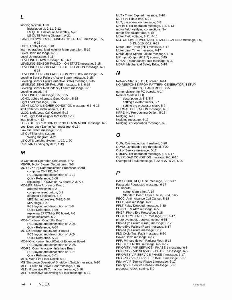
• INDEX 42-02-4022I-4
Llanding system, 1-19
installation of, 2-11, 2-12LS QUTE Enclosure Assembly, A-20LS QUTE Wiring Diagram, A-21
LANDING SYSTEM REDUNDANCY FAILURE message, 6-5, 6-15
LBBY, Lobby Floor, 5-18learn operations, load weigher learn operation, 5-19Level Down message, 6-15Level Up message, 6-15LEVELING DOWN message, 6-5, 6-15LEVELING SENSOR FAILED - ON STATE message, 6-15LEVELING SENSOR FAILED - OFF POSITION message, 6-5,
6-15LEVELING SENSOR FAILED - ON POSITION message, 6-5Leveling Sensor Failure (Active State) message, 6-15Leveling Sensor Failure (Inactive State) message, 6-15LEVELING SENSOR FAILURE message, 6-5, 6-15Leveling Sensor Redundancy Failure message, 6-15Leveling speed, 4-9LEVELING UP message, 6-5, 6-15LGNG, Lobby Alternate Gong Option, 5-18Light Load message, 6-16LIGHT LOAD WEIGHER CONDITION message, 6-5, 6-16limit switches, installation of, 2-11LLCC, Light Load Call Cancel, 5-18LLW, Light load weigher threshold, 5-19load testing, 4-12LOSS OF INSPECTION DURING LEARN MODE message, 6-5Lost Door Lock During Run message, 6-16Low Oil Switch message, 6-16LS QUTE landing system
Wiring Diagram, A-21LS-QUTE Landing System, 1-19, 1-20LS-STAN Landing System, 1-19
MM Contactor Operation Sequence, 6-72MBWR, Motor Blower Output timer, 5-8MC-CGP-4(8) Communication Processor Board
computer ON LED, 5-3PCB layout and description of, 1-15Quick Reference, 6-60replacing EPROMs or PC board, A-3, A-4
MC-MP2, Main Processor Boardaddress switches, 5-2computer reset button, 5-1diagnostic indicators, 5-2MP2 flag addresses, 5-28, 5-30MP2 flags, 5-27PCB layout and description of, 1-6Quick Reference, 6-59replacing EPROM or PC board, A-3status indicators, 5-2
MC-NC Neuron Controller BoardPCB layout and description of, A-24Quick Reference, A-34
MC-NIO Neuron Input/Output BoardPCB layout and description of, A-24Quick Reference, A-36
MC-NIO-X Neuron Input/Output Extender BoardPCB layout and description of, A-25
MC-RS, Communication Interface BoardPCB layout and description of, 1-15Quick Reference, 6-61
MFR, Main Fire Floor Recall, 5-18MG Shutdown Operation/ Shutdown Switch message, 6-16MLT - Failed to Leave Floor message, 6-16MLT - Excessive PI Correction message, 6-16MLT - Excessive Releveling at Floor message, 6-16
MLT - Timer Expired message, 6-16MLT / VLT data trap, 6-91MLT, car operation message, 6-8MnFire1, car operation message, 6-8, 6-13motor field, verifying connections, 3-4motor field failure fault, 4-18Motor Field voltage, 3-11, 4-11MOTOR LIMIT TIMER (ANTI-STALL) ELAPSED message, 6-5,
6-13, 6-16, 6-17, 6-19Motor Limit Timer (INT) message, 6-17Motor Limit Timer message, 6-17Motor Up to Speed Failure message, 6-29MP Input/Output (F11,7) screen, 6-45MPSAF Redundancy Fault message, 6-30MSAF, Mechanical Safety Edge, 5-18
NNetwork Status (F11, 1) screen, 6-44NO RESPONSE FROM PATTERN GENERATOR (SETUP
ERROR), LEARN MODE, 6-5nomenclature, for PC boards, A-14Normal Mode (EOD)
description of, 5-5, 5-7setting elevator timers, 5-7setting the processor clock, 5-9
NORMAL OPERATION message, 6-5NPRE, No Pre-opening Option, 5-18Nudging, 6-17Nudging message, 6-17Nudging, car operation message, 6-8
OOLW, Overloaded car threshold, 5-20OLW2, Overloaded car threshold, 5-20Out of Service message, 6-17OutServ, car operation message, 6-8, 6-17OVERLOAD CONDITION message, 6-5, 6-10Overspeed Fault message, 6-22, 6-27, 6-28, 6-30
PPASSCODE REQUEST message, 6-5, 6-17Passcode Requested message, 6-17PC boards
nomenclature for, A-14Standard Board Layout, 6-58, 6-64, 6-65
PECC, Anti-nuisance Call Cancel, 5-18PFLT Fault message, 6-30PFLT Relay Dropped message, 6-30PG NOT READY message, 6-5PHEP, Photo Eye Protection, 5-18PHOTO EYE FAILURE message, 6-5, 6-17photo eye input, troubleshooting, 6-51Photo-Eye Failure (Front) message, 6-17Photo-Eye Failure (Rear) message, 6-17Photo-Eye Failure message, 6-17PLD Cycle Test Fault message, 6-30Power Down message, 6-17PPF, Primary (lower) Parking Floor, 5-18PRE-TEST MODE message, 6-5, 6-17PRIORITY / VIP SERVICE - PHASE 1 message, 6-5PRIORITY / VIP SERVICE - PHASE 2 message, 6-5PRIORITY VIP SERVICE PHASE I message, 6-17PRIORITY VIP SERVICE PHASE II message, 6-17Priority/VIP Service Phase 1 message, 6-17Priority/VIP Service Phase 2 message, 6-17processor clock, setting, 5-9
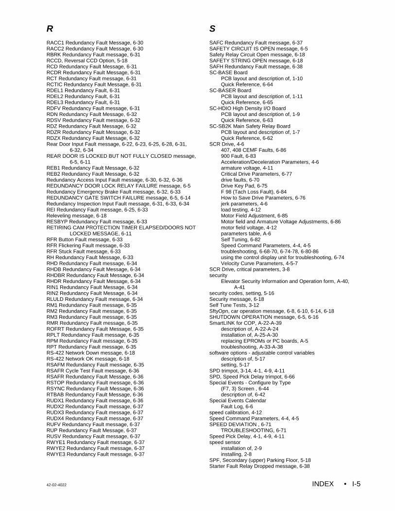
42-02-4022 INDEX • I-5
RRACC1 Redundancy Fault Message, 6-30RACC2 Redundancy Fault Message, 6-30RBRK Redundancy Fault message, 6-31RCCD, Reversal CCD Option, 5-18RCD Redundancy Fault Message, 6-31RCDR Redundancy Fault Message, 6-31RCT Redundancy Fault message, 6-31RCTIC Redundancy Fault Message, 6-31RDEL1 Redundancy Fault, 6-31RDEL2 Redundancy Fault, 6-31RDEL3 Redundancy Fault, 6-31RDFV Redundancy Fault message, 6-31RDN Redundancy Fault Message, 6-32RDSV Redundancy Fault message, 6-32RDZ Redundancy Fault Message, 6-32RDZR Redundancy Fault Message, 6-32RDZX Redundancy Fault Message, 6-32Rear Door Input Fault message, 6-22, 6-23, 6-25, 6-28, 6-31,
6-32, 6-34REAR DOOR IS LOCKED BUT NOT FULLY CLOSED message,
6-5, 6-11REB1 Redundancy Fault Message, 6-32REB2 Redundancy Fault Message, 6-32Redundancy Access Input Fault message, 6-30, 6-32, 6-36REDUNDANCY DOOR LOCK RELAY FAILURE message, 6-5Redundancy Emergency Brake Fault message, 6-32, 6-33REDUNDANCY GATE SWITCH FAILURE message, 6-5, 6-14Redundancy Inspection Input Fault message, 6-31, 6-33, 6-34REI Redundancy Fault message, 6-25, 6-33Releveling message, 6-18RESBYP Redundancy Fault message, 6-33RETIRING CAM PROTECTION TIMER ELAPSED/DOORS NOT
LOCKED MESSAGE, 6-11RFR Button Fault message, 6-33RFR Flickering Fault message, 6-33RFR Stuck Fault message, 6-33RH Redundancy Fault Message, 6-33RHD Redundancy Fault message, 6-34RHDB Redundancy Fault Message, 6-34RHDBR Redundancy Fault Message, 6-34RHDR Redundancy Fault Message, 6-34RIN1 Redundancy Fault Message, 6-34RIN2 Redundancy Fault Message, 6-34RLULD Redundancy Fault message, 6-34RM1 Redundancy Fault message, 6-35RM2 Redundancy Fault message, 6-35RM3 Redundancy Fault message, 6-35RMR Redundancy Fault message, 6-35ROFRT Redundancy Fault Message, 6-35RPLT Redundancy Fault message, 6-35RPM Redundancy Fault message, 6-35RPT Redundancy Fault message, 6-35RS-422 Network Down message, 6-18RS-422 Network OK message, 6-18RSAFM Redundancy Fault message, 6-35RSAFR Cycle Test Fault message, 6-36RSAFR Redundancy Fault Message, 6-36RSTOP Redundancy Fault message, 6-36RSYNC Redundancy Fault Message, 6-36RTBAB Redundancy Fault Message, 6-36RUDX1 Redundancy Fault message, 6-36RUDX2 Redundancy Fault message, 6-37RUDX3 Redundancy Fault message, 6-37RUDX4 Redundancy Fault message, 6-37RUFV Redundancy Fault message, 6-37RUP Redundancy Fault Message, 6-37RUSV Redundancy Fault message, 6-37RWYE1 Redundancy Fault message, 6-37RWYE2 Redundancy Fault message, 6-37RWYE3 Redundancy Fault message, 6-37
SSAFC Redundancy Fault message, 6-37SAFETY CIRCUIT IS OPEN message, 6-5Safety Relay Circuit Open message, 6-18SAFETY STRING OPEN message, 6-18SAFH Redundancy Fault message, 6-38SC-BASE Board
PCB layout and description of, 1-10Quick Reference, 6-64
SC-BASER BoardPCB layout and description of, 1-11Quick Reference, 6-65
SC-HDIO High Density I/O BoardPCB layout and description of, 1-9Quick Reference, 6-63
SC-SB2K Main Safety Relay BoardPCB layout and description of, 1-7Quick Reference, 6-62
SCR Drive, 4-6407, 408 CEMF Faults, 6-86900 Fault, 6-83Acceleration/Deceleration Parameters, 4-6armature voltage, 4-11Critical Drive Parameters, 6-77drive faults, 6-70Drive Key Pad, 6-75F 98 (Tach Loss Fault), 6-84How to Save Drive Parameters, 6-76jerk parameters, 4-6load testing, 4-12Motor Field Adjustment, 6-85Motor field and Armature Voltage Adjustments, 6-86motor field voltage, 4-12parameters table, A-6Self Tuning, 6-82Speed Command Parameters, 4-4, 4-5troubleshooting, 6-68-70, 6-74-78, 6-80-86using the control display unit for troubleshooting, 6-74Velocity Curve Parameters, 4-5-7
SCR Drive, critical parameters, 3-8security
Elevator Security Information and Operation form, A-40, A-41
security codes, setting, 5-16Security message, 6-18Self Tune Tests, 3-12SftyOpn, car operation message, 6-8, 6-10, 6-14, 6-18SHUTDOWN OPERATION message, 6-5, 6-16SmartLINK for COP, A-22-A-39
description of, A-22-A-24installation of, A-25-A-30replacing EPROMs or PC boards, A-5troubleshooting, A-33-A-38
software options - adjustable control variablesdescription of, 5-17setting, 5-17
SPD trimpot, 3-14, 4-1, 4-9, 4-11SPD, Speed Pick Delay trimpot, 6-66Special Events - Configure by Type
(F7, 3) Screen , 6-44description of, 6-42
Special Events CalendarFault Log, 6-6
speed calibration, 4-12Speed Command Parameters, 4-4, 4-5SPEED DEVIATION , 6-71
TROUBLESHOOTING, 6-71Speed Pick Delay, 4-1, 4-9, 4-11speed sensor
installation of, 2-9installing, 2-8
SPF, Secondary (upper) Parking Floor, 5-18Starter Fault Relay Dropped message, 6-38
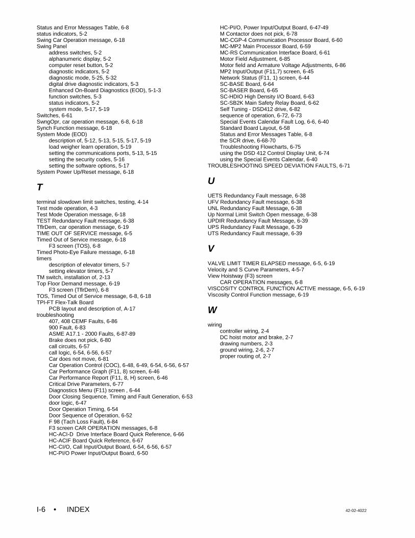
• INDEX 42-02-4022I-6
Status and Error Messages Table, 6-8status indicators, 5-2Swing Car Operation message, 6-18Swing Panel
address switches, 5-2alphanumeric display, 5-2computer reset button, 5-2diagnostic indicators, 5-2diagnostic mode, 5-25, 5-32digital drive diagnostic indicators, 5-3Enhanced On-Board Diagnostics (EOD), 5-1-3function switches, 5-3status indicators, 5-2system mode, 5-17, 5-19
Switches, 6-61SwngOpr, car operation message, 6-8, 6-18Synch Function message, 6-18System Mode (EOD)
description of, 5-12, 5-13, 5-15, 5-17, 5-19load weigher learn operation, 5-19setting the communications ports, 5-13, 5-15setting the security codes, 5-16setting the software options, 5-17
System Power Up/Reset message, 6-18
Tterminal slowdown limit switches, testing, 4-14Test mode operation, 4-3Test Mode Operation message, 6-18TEST Redundancy Fault message, 6-38TflrDem, car operation message, 6-19TIME OUT OF SERVICE message, 6-5Timed Out of Service message, 6-18
F3 screen (TOS), 6-8Timed Photo-Eye Failure message, 6-18timers
description of elevator timers, 5-7setting elevator timers, 5-7
TM switch, installation of, 2-13Top Floor Demand message, 6-19
F3 screen (TflrDem), 6-8TOS, Timed Out of Service message, 6-8, 6-18TPI-FT Flex-Talk Board
PCB layout and description of, A-17troubleshooting
407, 408 CEMF Faults, 6-86900 Fault, 6-83ASME A17.1 - 2000 Faults, 6-87-89Brake does not pick, 6-80call circuits, 6-57call logic, 6-54, 6-56, 6-57Car does not move, 6-81Car Operation Control (COC), 6-48, 6-49, 6-54, 6-56, 6-57Car Performance Graph (F11, 8) screen, 6-46Car Performance Report (F11, 8, H) screen, 6-46Critical Drive Parameters, 6-77Diagnostics Menu (F11) screen , 6-44Door Closing Sequence, Timing and Fault Generation, 6-53door logic, 6-47Door Operation Timing, 6-54Door Sequence of Operation, 6-52F 98 (Tach Loss Fault), 6-84F3 screen CAR OPERATION messages, 6-8HC-ACI-D Drive Interface Board Quick Reference, 6-66HC-ACIF Board Quick Reference, 6-67HC-CI/O, Call Input/Output Board, 6-54, 6-56, 6-57HC-PI/O Power Input/Output Board, 6-50
HC-PI/O, Power Input/Output Board, 6-47-49M Contactor does not pick, 6-78MC-CGP-4 Communication Processor Board, 6-60MC-MP2 Main Processor Board, 6-59MC-RS Communication Interface Board, 6-61Motor Field Adjustment, 6-85Motor field and Armature Voltage Adjustments, 6-86MP2 Input/Output (F11,7) screen, 6-45Network Status (F11, 1) screen, 6-44SC-BASE Board, 6-64SC-BASER Board, 6-65SC-HDIO High Density I/O Board, 6-63SC-SB2K Main Safety Relay Board, 6-62Self Tuning - DSD412 drive, 6-82sequence of operation, 6-72, 6-73Special Events Calendar Fault Log, 6-6, 6-40Standard Board Layout, 6-58Status and Error Messages Table, 6-8the SCR drive, 6-68-70Troubleshooting Flowcharts, 6-75using the DSD 412 Control Display Unit, 6-74using the Special Events Calendar, 6-40
TROUBLESHOOTING SPEED DEVIATION FAULTS, 6-71
UUETS Redundancy Fault message, 6-38UFV Redundancy Fault message, 6-38UNL Redundancy Fault Message, 6-38Up Normal Limit Switch Open message, 6-38UPDIR Redundancy Fault Message, 6-39UPS Redundancy Fault Message, 6-39UTS Redundancy Fault message, 6-39
VVALVE LIMIT TIMER ELAPSED message, 6-5, 6-19Velocity and S Curve Parameters, 4-5-7View Hoistway (F3) screen
CAR OPERATION messages, 6-8VISCOSITY CONTROL FUNCTION ACTIVE message, 6-5, 6-19Viscosity Control Function message, 6-19
Wwiring
controller wiring, 2-4DC hoist motor and brake, 2-7drawing numbers, 2-3ground wiring, 2-6, 2-7proper routing of, 2-7