Embed Size (px)
Citation preview
IOSR Journal of Computer Engineering (IOSR-JCE)
e-ISSN: 2278-0661,p-ISSN: 2278-8727, Volume 19, Issue 6, Ver. II (Nov.- Dec. 2017), PP 81-93
www.iosrjournals.org
DOI: 10.9790/0661-1906028193 www.iosrjournals.org 81 | Page
Controlling a 2D computer game with a Leap Motion
Georgi Krastev1, Valentina Voinohovska
2,Svetlozar Tsankov
3,Vanya Dineva
4
1(Computer Systems and Technologies, University of Ruse, Bulgaria)
2(Department of IIT, University of Ruse, Bulgaria)
3(Department of IIT, University of Ruse, Bulgaria)
4(Pedagogy, Psychology and History Department, University of Ruse, Bulgaria)
Abstract: The paper presents the process of developing a 2D computer game controlled by a Leap Motion
controller. The Leap Motion detects and tracks the movement of hands, fingers and fingerlike items (e.g. a ball-
point pen, pencil, stylus, etc.). The software of the device analyses the objects within its virtual field of view by
identifying the hands, fingers, and fingerlike items and storing the data of their positions, gestures and
movements. The virtual field has the shape of an inverted pyramid located at the device center. The controller
identifies motion models as representing gestures of user commands and follow-up mimic hand-shooting
gestures. The game is developed in Microsoft XNA Game Studio 4.0 programming languages C# and .NET
Framework (4.0).
Keywords-Computer Games, Leap Motion, Unified Modeling Language, XNA, 2D
I. Introduction A new generation of researchers consider video games their primary research interest. But the struggle
for acceptance and academic credibility can still be considerable. After all, we study video games, not a
phenomenon that epitomizes high-brow cultural expression [1]. Educational simulations and games engage
students in virtual worlds where they apply their knowledge, skills, and strategies to assigned roles or situations
[2, 3].
Computer simulations and games have great potential to catalyze this new approach. They enable
learners to see and interact with representations of natural phenomena that would otherwise be impossible to
observe – a process that helps them to formulate scientifically correct explanations for these phenomena.
Simulations and games can motivate learners with challenges and rapid feedback and tailor instruction to
individual learners‟ needs and interests [4]. Some researchers observed that teachers lack time to prepare for a
lesson using games and also lack the knowledge and skills, professional collaboration, and initiatives to explore
new method [5], though these are not mentioned by the teachers in the studies.
A computer game is a software application allowing user to control the course of action. It assumes the
participation of at least a single player who is able to interact within the surrounding area they have been placed.
The player aims at the game objective and can reach it simply if acting in a smart, skillful or daring way. Games
are widespread in various genres.
The idea of shooting objects is not innovative minding that it has been already implicated in many
diverse games. In 1984 Nintendo Entertainment System (NES), released the first version of the Duck Hunt.
Players use the NES Zapper to shoot targets (ducks) moving on the television screen. Targets appear one or two
at a time and the player is given three attempts to shoot them down. Duck Hunt was followed by a cloned
version, named Duck‟n‟Kill that was created during a 24 hour-hackathon in April, 2013. Its goal is hitting as
many ducks as possible before the timer goes off. The more ducks are shot down, the faster the game becomes.
Its advantage over Duck Hunt is that the player receives different number of points depending on the hit spots of
the ducks, and furthermore, an egg basket appears within a definite period of time extending the game duration.
This paper presents the process of designing and implementation of a computer game controlled by a
Leap Motion controller which integrates the advantages of the game solutions stated above. Leap Motion is a
peripheral device and software for computers allowing their free control by means of a user natural gesture-
based interface [6].
1. Designing and description of the proposed solution 1.1 Logical model of the software system
The logical model of the software system (SS) is described with the Unified Modeling Language
(UML) representing a family of graphical notations (of Grady Booth, Ivar Jacobson and Jim Rumbaugh). United
by a common meta-model, the graphical notations help to specify, visualize and document the requirements and
architecture of object-oriented software systems [7].
Controlling a 2D computer game with a Leap Motion
DOI: 10.9790/0661-1906028193 www.iosrjournals.org 82 | Page
UML has been recognized as a standard for graphical description of software projects owed to its language,
technology and platform independence.
Diagrams are implemented with the help of Microsoft Visual Studio 2013 (VS 2013) tools. A Modeling Project
is created for the purpose of graphical modeling of software projects that allows to automate part of the process
of the software project development.
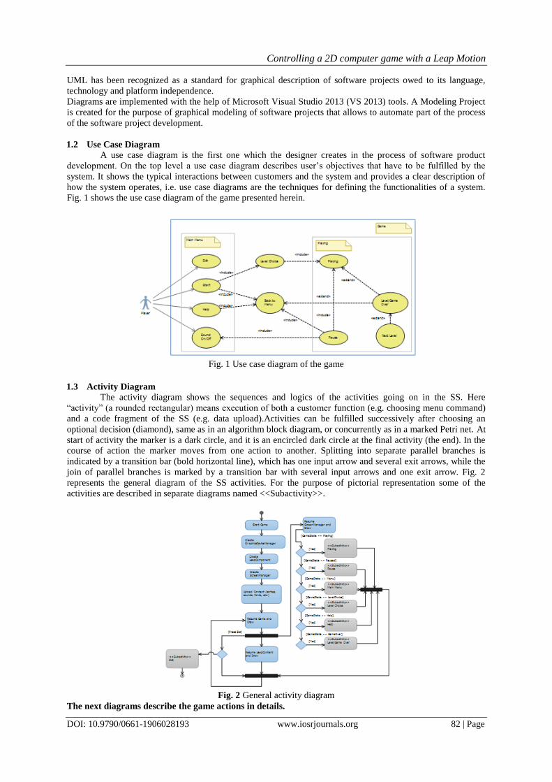
1.2 Use Case Diagram
A use case diagram is the first one which the designer creates in the process of software product
development. On the top level a use case diagram describes user‟s objectives that have to be fulfilled by the
system. It shows the typical interactions between customers and the system and provides a clear description of
how the system operates, i.e. use case diagrams are the techniques for defining the functionalities of a system.
Fig. 1 shows the use case diagram of the game presented herein.
Fig. 1 Use case diagram of the game
1.3 Activity Diagram
The activity diagram shows the sequences and logics of the activities going on in the SS. Here
“activity” (a rounded rectangular) means execution of both a customer function (e.g. choosing menu command)
and a code fragment of the SS (e.g. data upload).Activities can be fulfilled successively after choosing an
optional decision (diamond), same as in an algorithm block diagram, or concurrently as in a marked Petri net. At
start of activity the marker is a dark circle, and it is an encircled dark circle at the final activity (the end). In the
course of action the marker moves from one action to another. Splitting into separate parallel branches is
indicated by a transition bar (bold horizontal line), which has one input arrow and several exit arrows, while the
join of parallel branches is marked by a transition bar with several input arrows and one exit arrow. Fig. 2
represents the general diagram of the SS activities. For the purpose of pictorial representation some of the
activities are described in separate diagrams named <<Subactivity>>.
Fig. 2 General activity diagram
The next diagrams describe the game actions in details.
Controlling a 2D computer game with a Leap Motion
DOI: 10.9790/0661-1906028193 www.iosrjournals.org 83 | Page
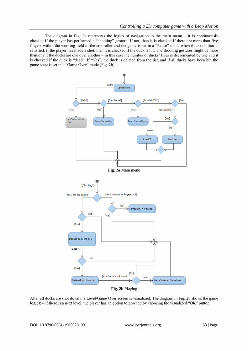
The diagram in Fig. 2a represents the logics of navigation in the main menu – it is continuously
checked if the player has performed a “shooting” gesture. If not, then it is checked if there are more than five
fingers within the working field of the controller and the game is set in a “Pause” mode when this condition is
satisfied. If the player has made a shot, then it is checked if the duck is hit. The shooting gestures might be more
than one if the ducks are one over another – in this case the number of ducks‟ lives is decremented by one and it
is checked if the duck is “dead”. If “Yes”, the duck is deleted from the list, and if all ducks have been hit, the
game state is set in a “Game Over” mode (Fig. 2b)
Fig. 2a Main menu
Fig. 2b Playing
After all ducks are shot down the Level/Game Over screen is visualized. The diagram in Fig. 2b shows the game
logics: – if there is a next level, the player has an option to proceed by choosing the visualized “OK” button.
Controlling a 2D computer game with a Leap Motion
DOI: 10.9790/0661-1906028193 www.iosrjournals.org 84 | Page
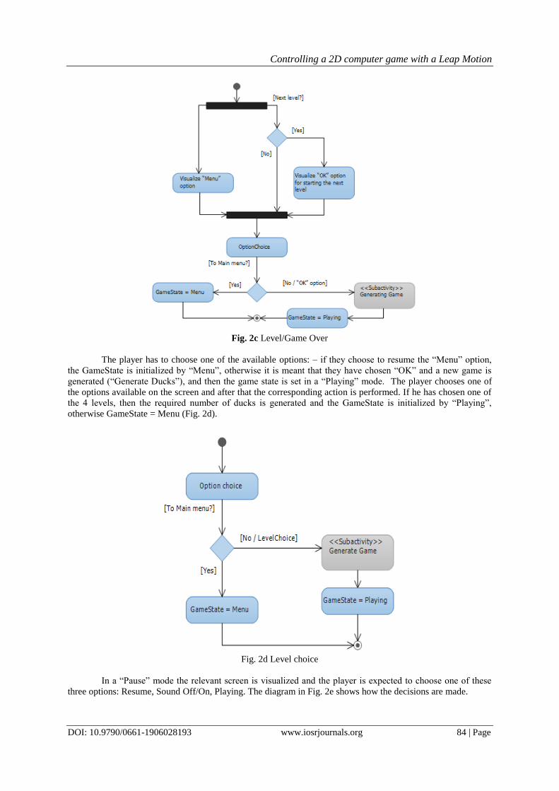
Fig. 2c Level/Game Over
The player has to choose one of the available options: – if they choose to resume the “Menu” option,
the GameState is initialized by “Menu”, otherwise it is meant that they have chosen “OK” and a new game is
generated (“Generate Ducks”), and then the game state is set in a “Playing” mode. The player chooses one of
the options available on the screen and after that the corresponding action is performed. If he has chosen one of
the 4 levels, then the required number of ducks is generated and the GameState is initialized by “Playing”,
otherwise GameState = Menu (Fig. 2d).
Fig. 2d Level choice
In a “Pause” mode the relevant screen is visualized and the player is expected to choose one of these
three options: Resume, Sound Off/On, Playing. The diagram in Fig. 2e shows how the decisions are made.
Controlling a 2D computer game with a Leap Motion
DOI: 10.9790/0661-1906028193 www.iosrjournals.org 85 | Page
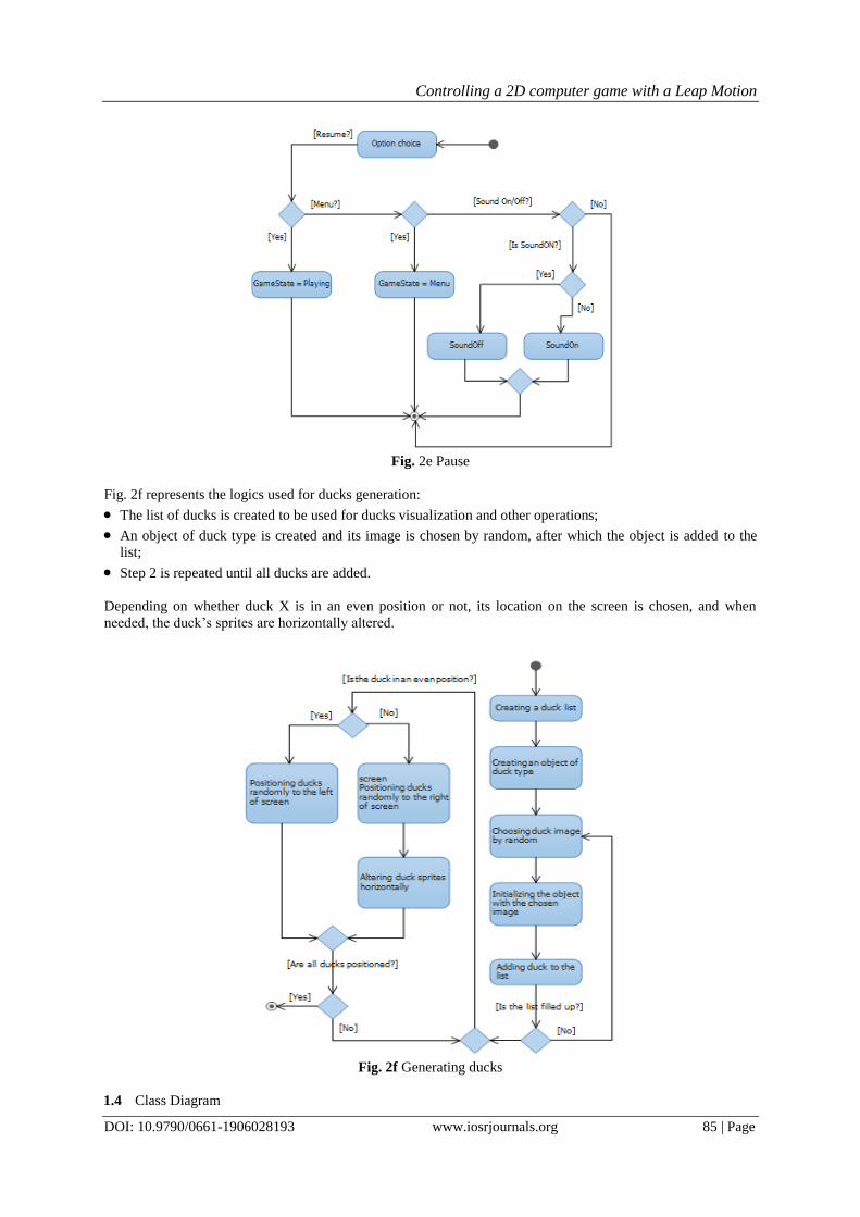
Fig. 2e Pause
Fig. 2f represents the logics used for ducks generation:
The list of ducks is created to be used for ducks visualization and other operations;
An object of duck type is created and its image is chosen by random, after which the object is added to the
list;
Step 2 is repeated until all ducks are added.
Depending on whether duck X is in an even position or not, its location on the screen is chosen, and when
needed, the duck‟s sprites are horizontally altered.
Fig. 2f Generating ducks
1.4 Class Diagram
Controlling a 2D computer game with a Leap Motion
DOI: 10.9790/0661-1906028193 www.iosrjournals.org 86 | Page
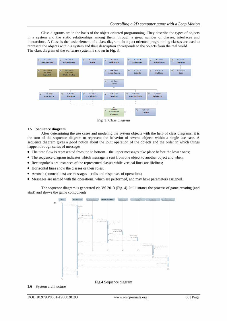
Class diagrams are in the basis of the object oriented programming. They describe the types of objects
in a system and the static relationships among them, through a great number of classes, interfaces and
interactions. A Class is the basic element of a class diagram. In object oriented programming classes are used to
represent the objects within a system and their description corresponds to the objects from the real world.
The class diagram of the software system is shown in Fig. 3.
Fig. 3. Class diagram
1.5 Sequence diagram
After determining the use cases and modeling the system objects with the help of class diagrams, it is
the turn of the sequence diagram to represent the behavior of several objects within a single use case. A
sequence diagram gives a good notion about the joint operation of the objects and the order in which things
happen through series of messages.
The time flow is represented from top to bottom – the upper messages take place before the lower ones;
The sequence diagram indicates which message is sent from one object to another object and when;
Rectangular„s are instances of the represented classes while vertical lines are lifelines;
Horizontal lines show the classes or their roles;
Arrow„s (connections) are messages – calls and responses of operations;
Messages are named with the operations, which are performed, and may have parameters assigned.
The sequence diagram is generated via VS 2013 (Fig. 4). It illustrates the process of game creating (and
start) and shows the game components.
Fig.4 Sequence diagram
1.6 System architecture
Controlling a 2D computer game with a Leap Motion
DOI: 10.9790/0661-1906028193 www.iosrjournals.org 87 | Page
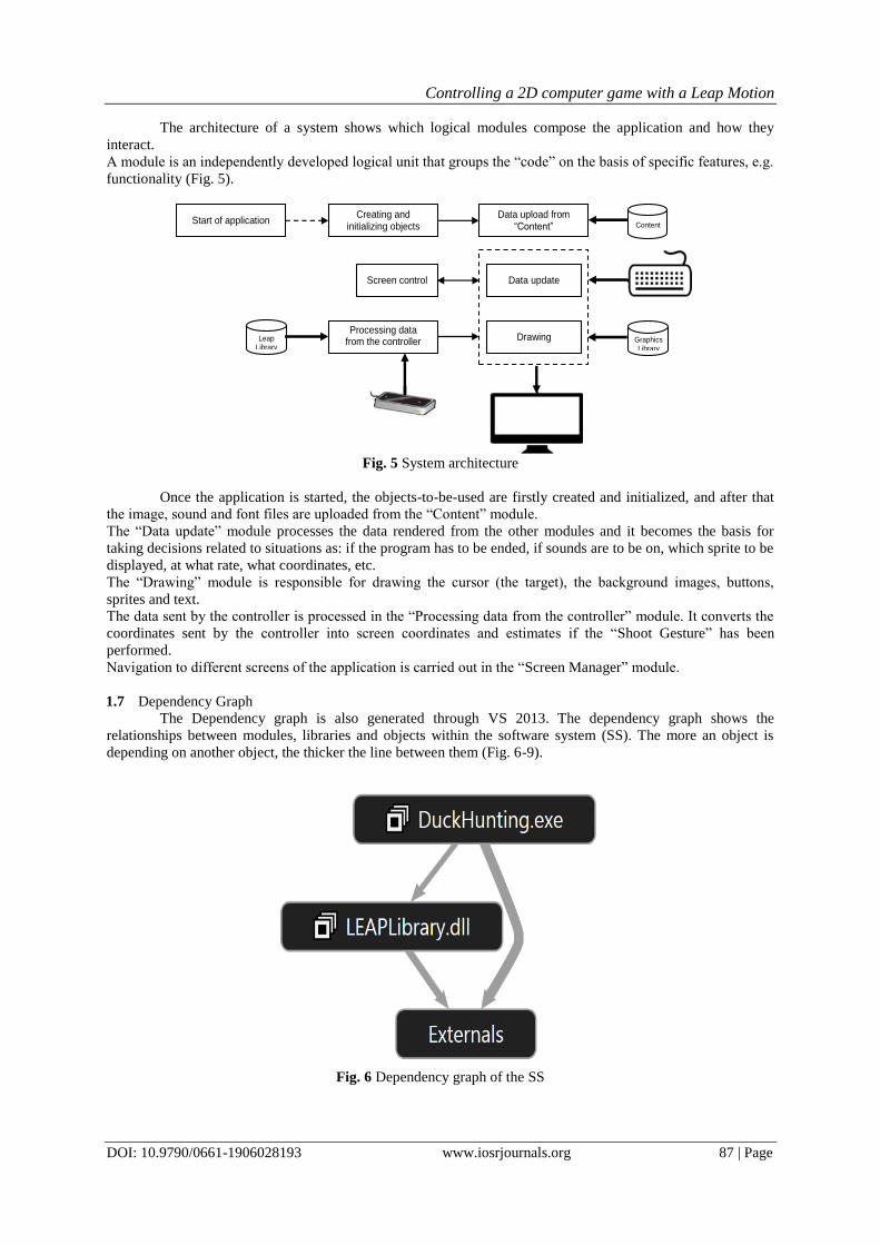
The architecture of a system shows which logical modules compose the application and how they
interact.
A module is an independently developed logical unit that groups the “code” on the basis of specific features, e.g.
functionality (Fig. 5).
Fig. 5 System architecture
Once the application is started, the objects-to-be-used are firstly created and initialized, and after that
the image, sound and font files are uploaded from the “Content” module.
The “Data update” module processes the data rendered from the other modules and it becomes the basis for
taking decisions related to situations as: if the program has to be ended, if sounds are to be on, which sprite to be
displayed, at what rate, what coordinates, etc.
The “Drawing” module is responsible for drawing the cursor (the target), the background images, buttons,
sprites and text.
The data sent by the controller is processed in the “Processing data from the controller” module. It converts the
coordinates sent by the controller into screen coordinates and estimates if the “Shoot Gesture” has been
performed.
Navigation to different screens of the application is carried out in the “Screen Manager” module.
1.7 Dependency Graph
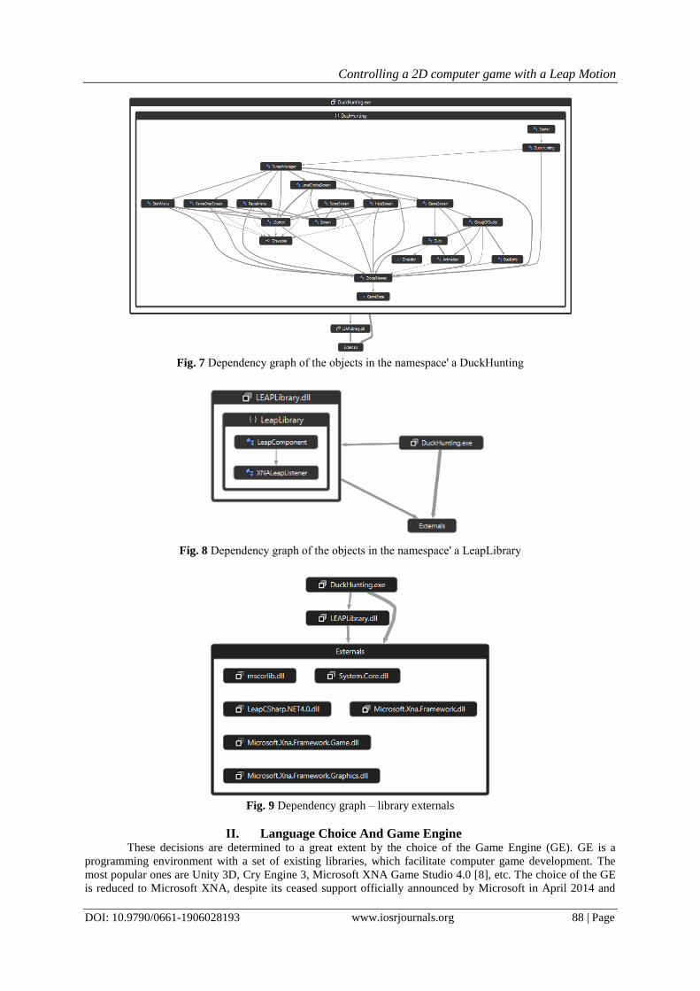
The Dependency graph is also generated through VS 2013. The dependency graph shows the
relationships between modules, libraries and objects within the software system (SS). The more an object is
depending on another object, the thicker the line between them (Fig. 6-9).
Fig. 6 Dependency graph of the SS
Graphics Library
Start of application Creating and
initializing objects Data upload from
“Content”
Screen control Data update
Processing data from the controller
Drawing
Content
Leap Library
Controlling a 2D computer game with a Leap Motion
DOI: 10.9790/0661-1906028193 www.iosrjournals.org 88 | Page
Fig. 7 Dependency graph of the objects in the namespace' а DuckHunting
Fig. 8 Dependency graph of the objects in the namespace' а LeapLibrary
Fig. 9 Dependency graph – library externals
II. Language Choice And Game Engine These decisions are determined to a great extent by the choice of the Game Engine (GE). GE is a
programming environment with a set of existing libraries, which facilitate computer game development. The
most popular ones are Unity 3D, Cry Engine 3, Microsoft XNA Game Studio 4.0 [8], etc. The choice of the GE
is reduced to Microsoft XNA, despite its ceased support officially announced by Microsoft in April 2014 and
Controlling a 2D computer game with a Leap Motion
DOI: 10.9790/0661-1906028193 www.iosrjournals.org 89 | Page
the need of Leap Motion controller‟s special support for Unity 3D. On the one hand, it is reasoned by the fact
that beginners in programming easily learn XNA, and on the other hand, XNA offers all the necessary tools for
implementing the assigned task. XNA determines the usage of Microsoft Visual Studio programming
environment, C# programming language and .NET Framework (4.0). Visual Studio does not support XNA
version 2012 and later, but the user can find a number of solutions for Visual Studio 2013 in the Internet.
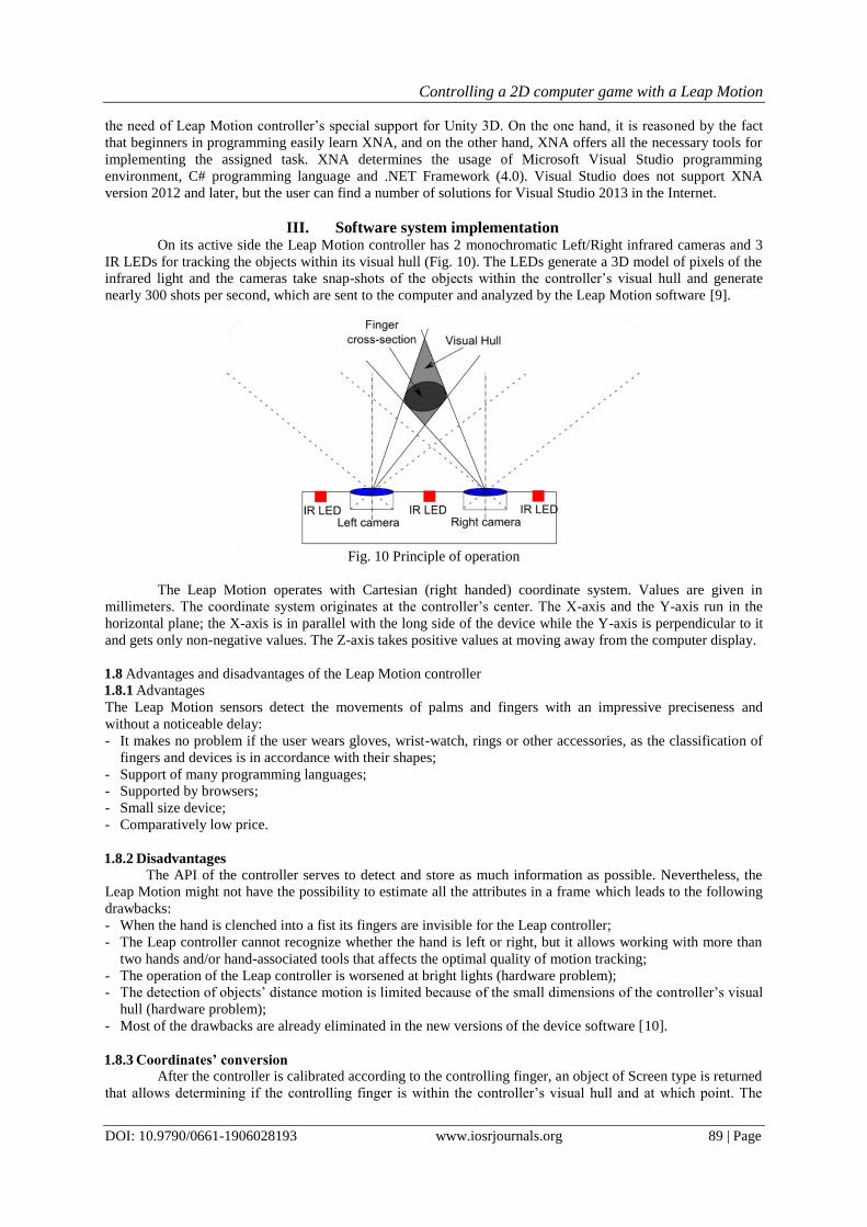
III. Software system implementation On its active side the Leap Motion controller has 2 monochromatic Left/Right infrared cameras and 3
IR LEDs for tracking the objects within its visual hull (Fig. 10). The LEDs generate a 3D model of pixels of the
infrared light and the cameras take snap-shots of the objects within the controller‟s visual hull and generate
nearly 300 shots per second, which are sent to the computer and analyzed by the Leap Motion software [9].
Fig. 10 Principle of operation
The Leap Motion operates with Cartesian (right handed) coordinate system. Values are given in
millimeters. The coordinate system originates at the controller‟s center. The X-axis and the Y-axis run in the
horizontal plane; the X-axis is in parallel with the long side of the device while the Y-axis is perpendicular to it
and gets only non-negative values. The Z-axis takes positive values at moving away from the computer display.
1.8 Advantages and disadvantages of the Leap Motion controller
1.8.1 Advantages
The Leap Motion sensors detect the movements of palms and fingers with an impressive preciseness and
without a noticeable delay:
- It makes no problem if the user wears gloves, wrist-watch, rings or other accessories, as the classification of
fingers and devices is in accordance with their shapes;
- Support of many programming languages;
- Supported by browsers;
- Small size device;
- Comparatively low price.
1.8.2 Disadvantages
The API of the controller serves to detect and store as much information as possible. Nevertheless, the
Leap Motion might not have the possibility to estimate all the attributes in a frame which leads to the following
drawbacks:
- When the hand is clenched into a fist its fingers are invisible for the Leap controller;
- The Leap controller cannot recognize whether the hand is left or right, but it allows working with more than
two hands and/or hand-associated tools that affects the optimal quality of motion tracking;
- The operation of the Leap controller is worsened at bright lights (hardware problem);
- The detection of objects‟ distance motion is limited because of the small dimensions of the controller‟s visual
hull (hardware problem);
- Most of the drawbacks are already eliminated in the new versions of the device software [10].
1.8.3 Coordinates’ conversion
After the controller is calibrated according to the controlling finger, an object of Screen type is returned
that allows determining if the controlling finger is within the controller‟s visual hull and at which point. The
Controlling a 2D computer game with a Leap Motion
DOI: 10.9790/0661-1906028193 www.iosrjournals.org 90 | Page
advantage of this method is that it provides the possibility to reduce user‟s hand quivering. Besides, the
coordinates‟ conversion (whenever necessary) is fast that prevents any noticeable delay:
Frame frame = controller.Frame();
// if fingers are detected
if (!frame.Hands.Empty)
{
// taking the uppermost finger
finger=frame.Hands.FirstOrDefault().Fingers.FirstOrDefault();
screen = null;
if (finger != null)
// calibration
screen=controller.CalibratedScreens.ClosestScreenHit(finger);
if (screen != null&&screen.IsValid)
{
// taking the normalized intersection point
Vector screenIntersect = screen.Intersect(finger, true);
Coordinates‟ conversion can be implemented by means of the following formula: screenX = ((leapX * WindowWidth * 2) / WindowWidth) + (WindowWidth / 2);
screenY = WindowHeight - leapY;
WindowWidth” and “WindowHeight” are respectively the width and height of the application window;
“leapX”, “leapY” – define the position of the object (e.g. finger) on the X- and Y- axis (within the device virtual
field); “screenX”, “screenY” are the screen coordinates. This method works relatively slower than the two
methods previously described.
Besides tracking hands, fingers and tools within its virtual field, the Leap Motion controls and updates
the uploaded data in a frame structure.Each frame has a list of data about hands, fingers and tools, as well as
detected gestures and factors, which describe the overall motion. When an object is detected it is assigned with a
unique identification number (ID) by the API of the controller. The ID is stored for the time when the detected
element remains visible within the virtual field. If the “connection” with the tracked object is lost for a moment,
the object may be assigned with another ID.
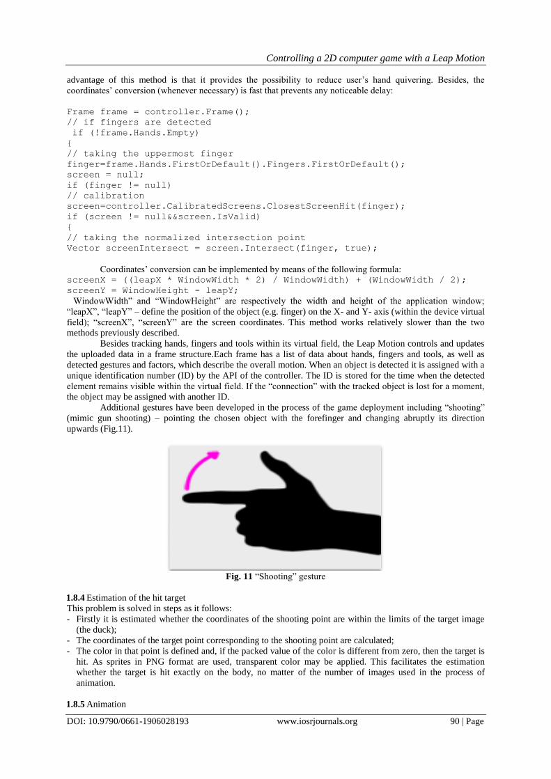
Additional gestures have been developed in the process of the game deployment including “shooting”
(mimic gun shooting) – pointing the chosen object with the forefinger and changing abruptly its direction
upwards (Fig.11).
Fig. 11 “Shooting” gesture
1.8.4 Estimation of the hit target
This problem is solved in steps as it follows:
- Firstly it is estimated whether the coordinates of the shooting point are within the limits of the target image
(the duck);
- The coordinates of the target point corresponding to the shooting point are calculated;
- The color in that point is defined and, if the packed value of the color is different from zero, then the target is
hit. As sprites in PNG format are used, transparent color may be applied. This facilitates the estimation
whether the target is hit exactly on the body, no matter of the number of images used in the process of
animation.
1.8.5 Animation
Controlling a 2D computer game with a Leap Motion
DOI: 10.9790/0661-1906028193 www.iosrjournals.org 91 | Page
A special class named “Animation” is created for animation of ducks. Its constructor must be assigned with
the following data:
- name of the sprite-to-be-animated – the images must be with equal width and height, arranged along the X-
axis;
- length of time when a sprite image remains visible;
- number of images in the sprite;
- whether the animation is continuously repeated, i.e. in a cycle;
- how many images in the sprite shall be used in specific situations, i.e. they are skipped in the normal cycle of
animation and positioned in the end of the sprite.
The sprites of ducks used in the application include images which must be continuously repeated as
well as images which are visualized only in special situations, i.e. when a duck is hit and when it is in attack
(envisaged for the further development of the application). For that reason the value of the last parameter in the
duck animation constructor must be 2.
1.8.6 Targets (Ducks) generation
“GroupOfDucks” is a special class created for targets generation. The parameter of its constructor is defined
with the number of targets to-be-generated. A list is created for targets storage. Generating targets and adding
targets to the list is implemented with the GenerateDucks() function.
The targets are generated one by one using a cycle with parameter for(). At first, a number corresponding to
some of the available targets is chosen by random. The object is created, the speed of the moving target is
estimated and the object is added to the list. When the cycle is ended the function RandomPosition() is called to
specify the starting coordinates of each object included in the list.
Fuzzy algorithm: void GenerateDucks()
{Duck currentDuck = null;
For(i from 0 to number_of_ducks)
{ Choose_kind_of_duck;
currentDuck = chosen_duck;
Estimate_speed_of_motion;
list.add(currentDuck);
}Specify_coordinates_of_each_duck – RandomPosition();
}
1.8.7 Screen manager
Navigation to playing screens is implemented by means of “if-else” check. An object of GameState
type is used to indicate the current screen. Depending on its value the corresponding screen is visualized.
Possible values are listed below: GameState.Menu – screen “main menu”;
GameState.LevelChoice – screen “level choice”;
GameState.Playing – screen “playing”;
GameState.Paused – screen “pause”;
GameState.GameOver – screen “level/game over”;
GameState.Help – screen “help”;
GameState.Score – screen “scores” – envisaged for the further development
of the application;
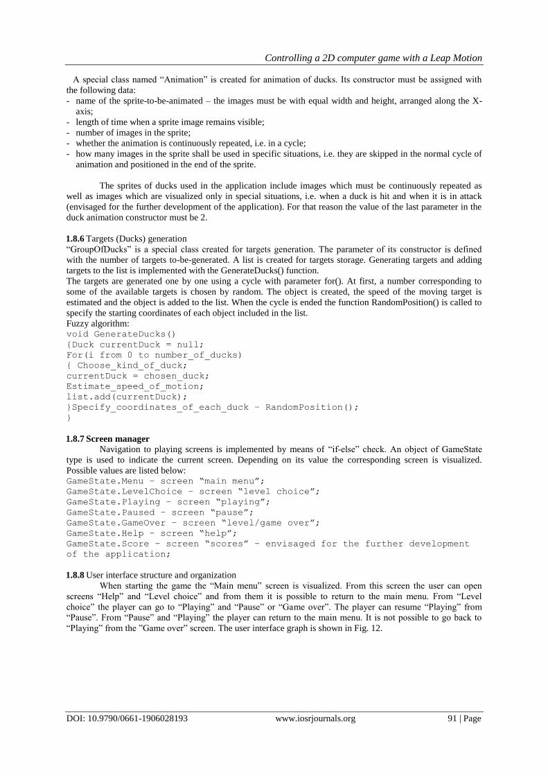
1.8.8 User interface structure and organization
When starting the game the “Main menu” screen is visualized. From this screen the user can open
screens “Help” and “Level choice” and from them it is possible to return to the main menu. From “Level
choice” the player can go to “Playing” and “Pause” or “Game over”. The player can resume “Playing” from
“Pause”. From “Pause” and “Playing” the player can return to the main menu. It is not possible to go back to
“Playing” from the ”Game over” screen. The user interface graph is shown in Fig. 12.
Controlling a 2D computer game with a Leap Motion
DOI: 10.9790/0661-1906028193 www.iosrjournals.org 92 | Page
Fig. 12. User interface graph
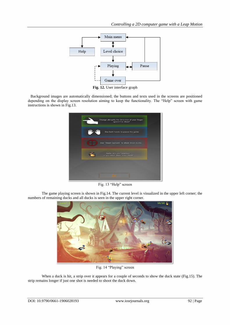
Background images are automatically dimensioned; the buttons and texts used in the screens are positioned
depending on the display screen resolution aiming to keep the functionality. The “Help” screen with game
instructions is shown in Fig.13.
Fig. 13 “Help” screen
The game playing screen is shown in Fig.14. The current level is visualized in the upper left corner; the
numbers of remaining ducks and all ducks is seen in the upper right corner.
Fig. 14 “Playing” screen
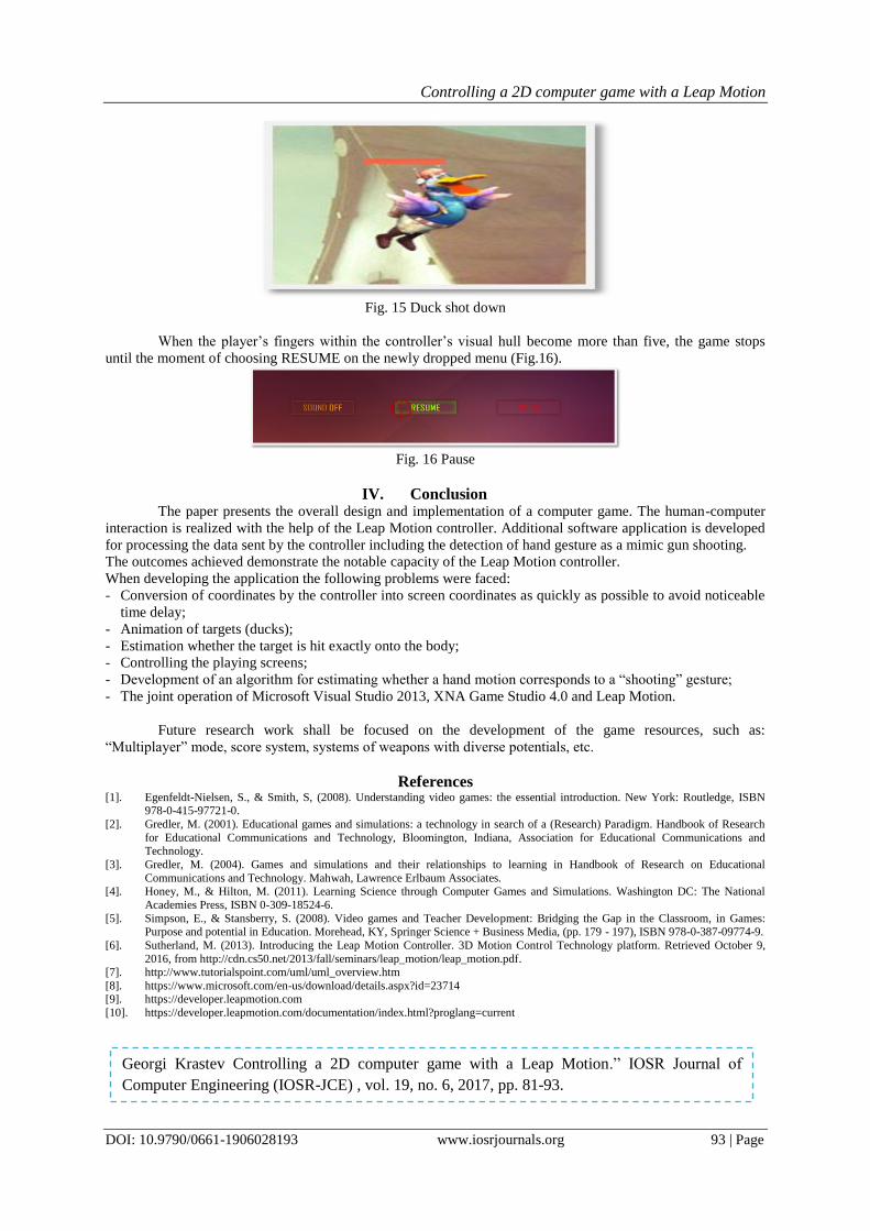
When a duck is hit, a strip over it appears for a couple of seconds to show the duck state (Fig.15). The
strip remains longer if just one shot is needed to shoot the duck down.
Controlling a 2D computer game with a Leap Motion
DOI: 10.9790/0661-1906028193 www.iosrjournals.org 93 | Page
Fig. 15 Duck shot down
When the player‟s fingers within the controller‟s visual hull become more than five, the game stops
until the moment of choosing RESUME on the newly dropped menu (Fig.16).
Fig. 16 Pause
IV. Conclusion The paper presents the overall design and implementation of a computer game. The human-computer
interaction is realized with the help of the Leap Motion controller. Additional software application is developed
for processing the data sent by the controller including the detection of hand gesture as a mimic gun shooting.
The outcomes achieved demonstrate the notable capacity of the Leap Motion controller.
When developing the application the following problems were faced:
- Conversion of coordinates by the controller into screen coordinates as quickly as possible to avoid noticeable
time delay;
- Animation of targets (ducks);
- Estimation whether the target is hit exactly onto the body;
- Controlling the playing screens;
- Development of an algorithm for estimating whether a hand motion corresponds to a “shooting” gesture;
- The joint operation of Microsoft Visual Studio 2013, XNA Game Studio 4.0 and Leap Motion.
Future research work shall be focused on the development of the game resources, such as:
“Multiplayer” mode, score system, systems of weapons with diverse potentials, etc.
References [1]. Egenfeldt-Nielsen, S., & Smith, S, (2008). Understanding video games: the essential introduction. New York: Routledge, ISBN
978-0-415-97721-0.
[2]. Gredler, M. (2001). Educational games and simulations: a technology in search of a (Research) Paradigm. Handbook of Research
for Educational Communications and Technology, Bloomington, Indiana, Association for Educational Communications and Technology.
[3]. Gredler, M. (2004). Games and simulations and their relationships to learning in Handbook of Research on Educational
Communications and Technology. Mahwah, Lawrence Erlbaum Associates. [4]. Honey, M., & Hilton, M. (2011). Learning Science through Computer Games and Simulations. Washington DC: The National
Academies Press, ISBN 0-309-18524-6.
[5]. Simpson, E., & Stansberry, S. (2008). Video games and Teacher Development: Bridging the Gap in the Classroom, in Games: Purpose and potential in Education. Morehead, KY, Springer Science + Business Media, (pp. 179 - 197), ISBN 978-0-387-09774-9.
[6]. Sutherland, M. (2013). Introducing the Leap Motion Controller. 3D Motion Control Technology platform. Retrieved October 9,
2016, from http://cdn.cs50.net/2013/fall/seminars/leap_motion/leap_motion.pdf.
[7]. http://www.tutorialspoint.com/uml/uml_overview.htm
[8]. https://www.microsoft.com/en-us/download/details.aspx?id=23714 [9]. https://developer.leapmotion.com
[10]. https://developer.leapmotion.com/documentation/index.html?proglang=current
Georgi Krastev Controlling a 2D computer game with a Leap Motion.” IOSR Journal of
Computer Engineering (IOSR-JCE) , vol. 19, no. 6, 2017, pp. 81-93.
.


![Leap motion [Шаповалов В.О.]](https://img.pdfslide.net/doc/110x75/558b3c24d8b42a29058b45cc/leap-motion--558c2483ed9bd.jpg)


![[Pause Café] Leap Motion](https://img.pdfslide.net/doc/110x75/558c81d2d8b42adf268b4692/pause-cafe-leap-motion.jpg)
