Embed Size (px)
Citation preview
Abstract — This paper describes the design and
implementation of a self-balancing two-wheeled robot, the Equilibrist Robot. The system is similar to the classical unstable, non-linear mechanical control problem of an inverted pendulum on a cart. Using the Linear Quadratic Regulator method and PID for state feedback, this paper shows a control algorithm that solves this problem. This control is able to reject disturbances and stabilize the system using a gyroscope. The control algorithm is implemented using Matlab and C-programing. The Equilibrist manages to stabilize itself in an upright position, reject disturbances and change its position.
Index Terms — Inverted Pendulum, Linear Quadratic Regulator, Servo and Regulator Control, Lego Robot.
I. INTRODUCTION
obile robots have been the focus of study among the scientific community. Their practical applications range from search and rescue activities, materials
handling and entertainment, among others [1]. The two-wheeled inverted pendulum (TWIP) robot is a
specific configuration of mobile robots that has been receiving special attention. In fact, their particular structure, unstable dynamic performance, and nonlinearity make them the ideal platform to demonstrate and test different nonlinear control theories [1]. TWIP has been applied in different areas, from commercial application to educational and research purposes.
The Segway Personal Transporter [2] is a well-known example of a commercial product. Segway’s robotics platforms are applied to different market segments including: research and development, indoor/outdoor navigation and path planning, industrial automation, and defence applications.
In [3], the authors present an embedded and standalone inverted pendulum with two piezoelectric drives designed as teaching aid for Mechatronics courses. The platform combines Mechanics, Electronics and Process Control
Manuscript received March 23, 2015; revised April 06, 2015. This work
has been supported by FCT - Fundação para a Ciência e Tecnologia in the scope of the project: PEst-UID/CEC/00319/2013.
Vinicius Siva is with the Industrial Electronics Department, Campus de Azurém, 4800-058 Guimarães, Portugal ([email protected]).
Pedro Leite is with the Industrial Electronics Department, Campus de Azurém, 4800-058 Guimarães, Portugal ([email protected]).
Filomena Soares is with the Industrial Electronics Department, Algoritmi R&D Center, Engineering School, Campus de Azurém, 4800-058 Guimarães, Portugal, (corresponding author phone: +351253510180; fax: +351253510179; e-mail: [email protected]).
Gil Lopes is with the Algoritmi R&D Center, Engineering School, Campus de Azurém, 4800-058 Guimarães, Portugal, ([email protected]).
João Sena Esteves is with the Industrial Electronics Department, Algoritmi R&D Center, Engineering School, Campus de Azurém, 4800-058 Guimarães, Portugal, ([email protected]).
Paulo Garrido is with the Industrial Electronics Department, Algoritmi R&D Center, Engineering School, Campus de Azurém, 4800-058 Guimarães, Portugal, ([email protected]).
topics where the students can understand and test the main principles of piezoelectric materials, mechanics, electricity and control theory as well as program and control the system with three independent microprocessors.
An application of the inverted pendulum system focused on biomechanics is presented in [4]. The goal of the study was to implement an accurate control algorithm (Fuzzy control) to regulate the speed of the robotic device, LOKOMAT® [5], intended for rehabilitation of patients with lower extremity paralysis. The application was first virtually simulated and tested in Matlab to verify proper operation. An analogy was performed between the robotic device and the inverted pendulum system: the pendulum movable mass matches with legs mass, and the pendulum mass with torso mass. Hence, to control LOKOMAT®, the patient only needs to bend his/her torso. A LOKOMAT® system can be adapted to any user as it has a calibration routine (introduction of patient data – height and weight) before running the fuzzy control algorithm.
There have been other TWIP architectures successfully designed and constructed. Jianhai et. al. (2014) [6] proposed a two-wheeled, self-balancing robot using 6-axis MEMS sensors MPU6050 to measure its posture (algorithm for sensor fusion of 3-axis gyroscope and 3-axis accelerometer). The complement filter (integrating the data of the gyroscope and accelerometer) was designed in order to achieve a more accurate inclination angle. A 16-bit MCU implements the PID control algorithm to calculate the required control voltage for the motors, to adjust the robot’s posture and keep the body balanced. The PID parameters were tested through experiments.
In [7], the authors present the control method of combining LQR and PID for a two-wheeled self-balancing robot that successfully overcomes the impact of the constraints on the linearized system.
Juang and Lum (2013) [8] report the design, construction and control of a two-wheeled self-balancing robot based on a pair of DC motors, an Arduino microcontroller board, a single-axis gyroscope and a 2-axis accelerometer. Also, a complementary filter was implemented to compensate the gyro drifts. PID and LQR-based PI-PD control designs were performed on the linearized equations of motion. Experimental results showed that self-balancing can be achieved with PI-PD control in the vicinity of the upright position.
The performance of the inverted pendulum platform when feedback force is provided has been reported in [9]. This study presents a virtual pendulum system based on OpenGL controlled with a joystick. The dynamical model of the system was obtained though mathematical manipulation and the feedback force was introduced into the system, providing an interactive operation mode.
In [10], a two-wheeled self-balancing robot transporter model was established. Kinematic and dynamic models
Controlling an Equilibrist Lego Robot
Vinicius Silva, Pedro Leite, Filomena Soares, Gil Lopes, João Sena Esteves and Paulo Garrido
M
Proceedings of the World Congress on Engineering 2015 Vol I WCE 2015, July 1 - 3, 2015, London, U.K.
ISBN: 978-988-19253-4-3 ISSN: 2078-0958 (Print); ISSN: 2078-0966 (Online)
WCE 2015
were developed as well as two control methods: the Proportional, Integral and Derivative (PID) algorithm and the Linear Quadratic Regulator (LQR). The control objectives includes self-balancing (preventing system from falling down when it moves forward or backward) and yaw rotation (steering angle regulation when it turns left or right). PID is used to control self-balancing and yaw rotation and LQR is used to control self-balancing only. The controllers’ performance was tested using Matlab simulations. Results point out a better performance of LQR than PID for self-balancing control.
Vasudevan et. al. (2015) [11] presented a study on the design for wheeled inverted pendulum (WIP) platforms highlighting the effect of the design choices on the balancing performance. In particular, they analysed the effect of soft viscoelastic tires (soft tires enhances balancing performance); the effect of pitch rate and wheel velocity filters (suggestions for design of filters); the existence of a self-tuning limit-cycle compensation algorithm; the effects of torque and velocity control of WIP motors; the effect of motor gearing on WIP dynamics. The overall goal was to define electromechanical design trade-offs to design and implement an efficient WIP platform.
This paper shows the design and implementation of a self-balancing Lego robot (Equilibrist Robot), which is an unstable system. The model is based on the inverted pendulum balancing on two wheels. This work shows the mathematical equations of the model as well as the full implementation of a control system stabilizing the robot.
The aims of this project includes: stabilize in an upright position; reject disturbances; forward motion, controlled via Bluetooth; avoid obstacles.
II. TWO-WHEEL STRUCTURE
The behaviour of this system, the self-balancing robot, is similar to the classical mechanical system of an inverted pendulum on a cart. It is a well-known system and its popularity derives in part from the fact that it is unstable without control. The fundamental principle within this control system can be found in many industrial applications, such as stability control of walking robots.
A. Lego Robot Configuration
The robot was built using Lego Mindstorms®, Lego NXT, which is an educational product released by Lego. The structure was primarily designed with the aid of the Lego modelling program, Lego Digital Designer. The Equilibrist Lego Robot is presented in Fig.1.
The hardware included in the Lego NXT consists of two microcontrollers, a master 32-bit (Atmel AT91SAM7) and a secondary 8-bit (ATmega48), Bluetooth communication module, display, USB communication, among other characteristics. The NXT version used in this work is equipped with a 32-bit ARM7 microprocessor running the RobotC firmware.
Table I presents the list of parameters and corresponding numerical values considered in this work for the Equilibrist Robot.
Fig.1. Configuration of the Equilibrist Lego Robot.
TABLE I
LIST OF PARAMETERS AND NUMERICAL VALUES USED Parameter Value Description
M = 0.522 [kg] Body weight W = 0.14 [m] Body width D = 0.065 [m] Body depth H = 0.267 [m] Body height m = 0.01692 [kg] Wheel weight R = 0.03 [m] Wheel radius L=H/2 [m] Distance of the centre of
mass to the wheels’ axis Jψ = ML^2/3 [kgm2] Body pitch inertia
moment Jϕ = M(W2+D2)/12
[kgm2] Body yaw inertia moment
Jm = 1×10E–5 [kgm2] DC motor inertia moment Rm = 6.69 [Ω] DC motor resistance Kb = 0.468 [V sec/rad] EMF constant Kt = 0.317 [Nm/A] DC motor torque constant N = 1 Gear ratio fm = 0.0022 [Nm/(rad/s)] Friction coefficient
between body and DC motor
fw = 0 Friction coefficient between wheel and floor
g = 9.81 [m/sec2] Gravity acceleration
The parameters used for the DC motors were found in [12], [13]. The expressions for the body pitch and yaw moments of inertia and the values for the friction coefficients were also taken from [12], [13].
B. Gyro Sensor
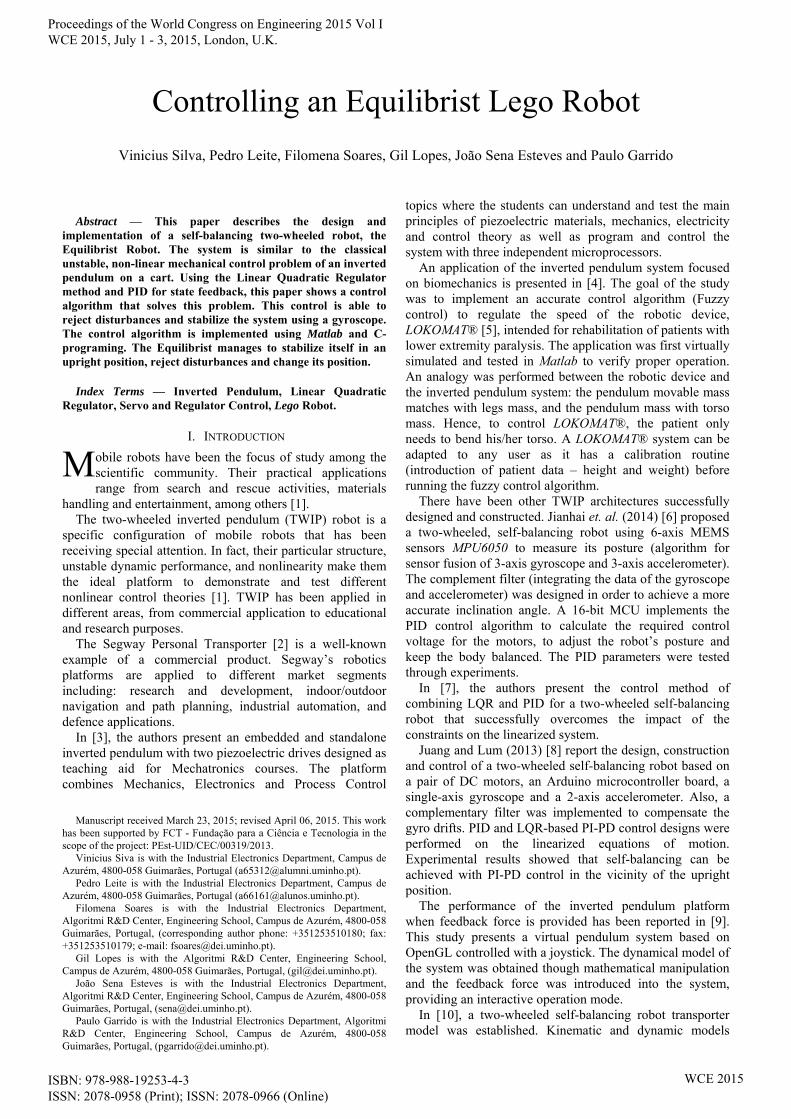
The sensor used in this work was a Gyroscope from Dexter Industries. The problem of using a gyroscope is that its value drifts over time. In Fig 2 the drift of the angular position is visible.
In order to solve this problem a recursive filter was implemented following equation (1):
)(*)1()1(* kOakOaoffset (1)
where O(k) is the current value being read and O(k–1) is the previous one.
The gyro filtered value is constantly updated by adding a percentage of the previous and the current gyro values. To determine the angular velocity, the signal from the gyro was used directly after applying the recursive filter.
In order to reconstruct the angle, the gyroscope signal was integrated. Through trial and error procedure, a value of a = 0.99 in the filter was found to correct the angle
Proceedings of the World Congress on Engineering 2015 Vol I WCE 2015, July 1 - 3, 2015, London, U.K.
ISBN: 978-988-19253-4-3 ISSN: 2078-0958 (Print); ISSN: 2078-0966 (Online)
WCE 2015
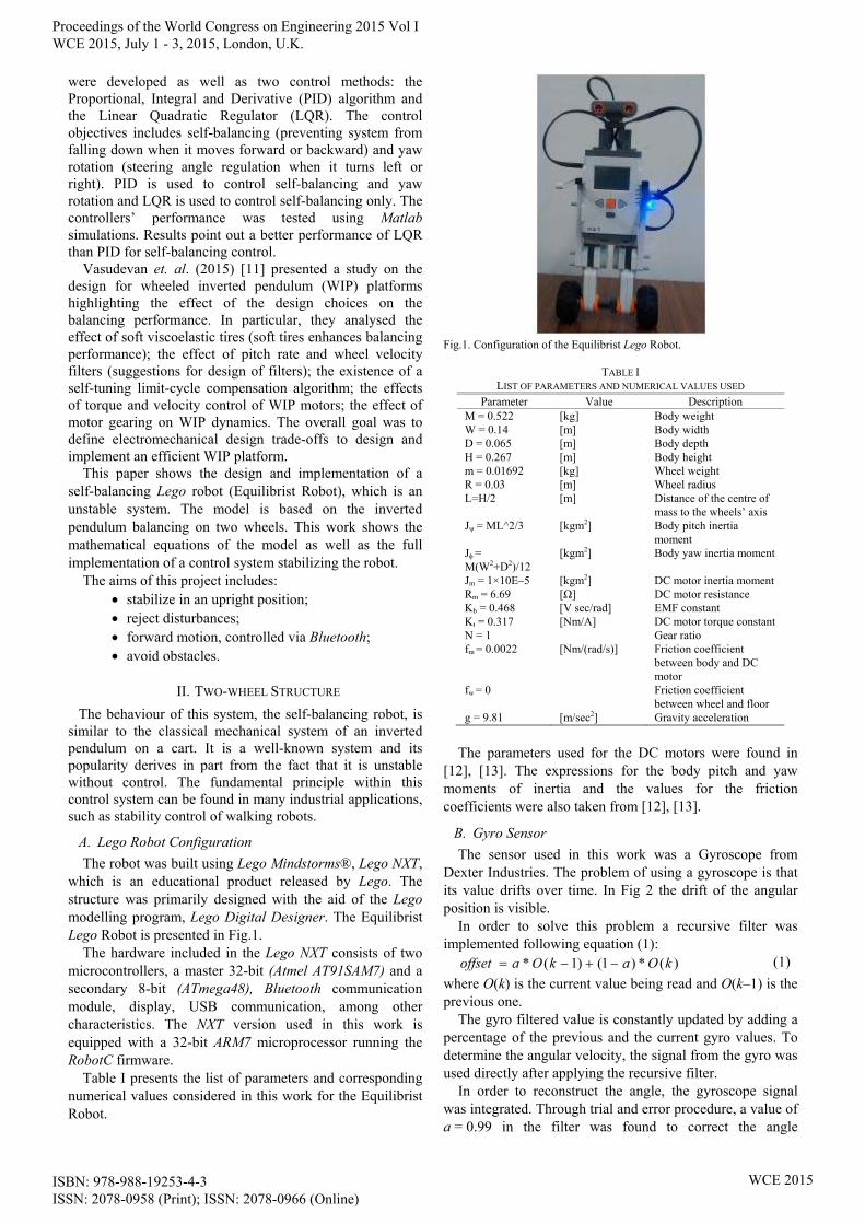
estimates. In Fig 3 the integration of gyroscope measurement with the filter implementation is shown: the angular position value is approximately zero when the gyro is stationary.
Fig.2. Integration of gyroscope measurements without filter: initially the angular position is zero (gyro stationary); after altering the position of the gyro sensor the stationary value has drifted.
Fig.3. Integration of gyroscope measurements with filter: the angular position value is approximately zero when the gyro is stationary.
C. Bluetooth communication
The NXT has the possibility to communicate via Bluetooth with a PC, mobile phones or others NXTs. In this work, Bluetooth communication was used to control the position of the robot. The protocol used was based on the Lego protocol and it can be found in [14].
III. MATHEMATICAL MODEL
The mathematical model used in this project was based on the NXTway-GS documentation. For more details see [12] and [13].
A. Open Loop
The state-space vector considers the motor angle , the body angle , the motor velocity ’ and the body velocity ’ as state-space variables (2).
1x (2)
The state-space equation and matrices are shown in (3), (4) and (5), where u is the vector of the two voltages applied to the motors.
uBxAx 1111 (3)
)4,4()3,4()2,4(0
)4,3()3,3()2,3(0
1000
0100
111
1111
AAA
AAAA
(4)
)4()4(
)3()3(
00
00
11
111
BB
BBB
(5)
where:
2
m22
m2
m2
w2
w
mmbt
mt
E_12-E_22*E_11=detE
J*n*2+J+L*M=E_22
J*n*2-R*L*M=E_12
J*n*2+J*2+R*M)+m*(2=E_11
f+beta=tmp
f+/RK*K*n=beta
/RK*n=alpha
)/detE E_12 + E_11 (*alpha- = (4)B
)/detE E_12 + E_22 (*alpha = (3)B
)/detE E_12 + E_11 (*beta*2- = (4,4)A
)/detE E_12 + E_22 (*beta*2 = (3,4)A
)/detE E_11*beta + E_12*(tmp*2 = (4,3)A
)/detE E_12*beta + E_22*(tmp*2- = (3,3)A
E_11/detE*L*M*g = (4,2)A
E_12/detE*L*M*g- = (3,2)A
1
1
1
1
1
1
1
1
The open loop response was simulated in Matlab with different initial conditions. The system showed an unstable behaviour.
B. Closed Loop: Linear Quadratic Regulator
The Linear Quadratic Regulator (LQR) method was implemented to stabilize and control the system and reduce steady-state errors by providing feedback weighting for the input parameters.
Considering system inputs and outputs (4th order system), and noting that there is now an additional state due to an integrator being included in the feedback loop of the body pitch variable, matrices A1 and B1 are then defined as:
00001
0)4,4()3,4()2,4(0
0)4,3()3,3()2,3(0
01000
00100
111
1111
AAA
AAAA (6)
00
)4()4(
)3()3(
00
00
11
111
BB
BBB (7)
and the feedback equation (8).
154321
543211 x
kkkkk
kkkkkKxu
(8)
The reason why there are two identical feedback control
Proceedings of the World Congress on Engineering 2015 Vol I WCE 2015, July 1 - 3, 2015, London, U.K.
ISBN: 978-988-19253-4-3 ISSN: 2078-0958 (Print); ISSN: 2078-0966 (Online)
WCE 2015
signals is that the control action is divided between two actuators, and due to the symmetry, the same gains are used for the left and right controller.
Using the NXTway-GS documentations, the following Q and R matrices were used [12]:
2
5
1040000
01000
00100
0001060
00001
x
x
Q (9)
3
3
100
010R (10)
The LQR function in Matlab was then used to determine specified weights for each of the controller feedbacks. The feedback controller weightings are listed in Table II. The closed-loop step response is shown in Fig. 4.
TABLE II LIST OF GAINS.
Variable Gain Value Motor Angle k1 –0.8398 Gyro Angle k2 –48.229
Motor Velocity k3 –1.1070 Gyro Velocity k4 –5.9712 Integral Gain k5 –0.4472
IV. IMPLEMENTATION
During the implementation of the Equilibrist Robot some considerations were taken into account regarding sampling frequency definition, controller performance, tasks priority and requisites for servo command implementation.
Fig.4. Closed-loop step response.
A. Control System
The sampling frequency used (which was the same frequency used for updating the controller) was 100 Hz. The sampling frequency was chosen based on the results from the LQR simulation shown in the previous chapter.
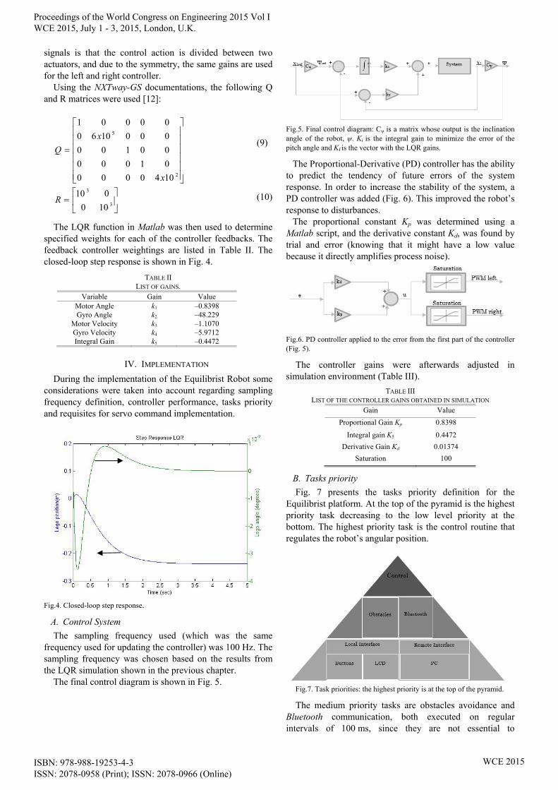
The final control diagram is shown in Fig. 5.
Fig.5. Final control diagram: Cψ is a matrix whose output is the inclination angle of the robot, ψ. Ki is the integral gain to minimize the error of the pitch angle and Kf is the vector with the LQR gains.
The Proportional-Derivative (PD) controller has the ability to predict the tendency of future errors of the system response. In order to increase the stability of the system, a PD controller was added (Fig. 6). This improved the robot’s response to disturbances.
The proportional constant Kp was determined using a Matlab script, and the derivative constant Kd, was found by trial and error (knowing that it might have a low value because it directly amplifies process noise).
Fig.6. PD controller applied to the error from the first part of the controller (Fig. 5).
The controller gains were afterwards adjusted in simulation environment (Table III).
TABLE III LIST OF THE CONTROLLER GAINS OBTAINED IN SIMULATION
Gain Value
Proportional Gain Kp 0.8398
Integral gain K5 0.4472
Derivative Gain Kd 0.01374
Saturation 100
B. Tasks priority
Fig. 7 presents the tasks priority definition for the Equilibrist platform. At the top of the pyramid is the highest priority task decreasing to the low level priority at the bottom. The highest priority task is the control routine that regulates the robot’s angular position.
Fig.7. Task priorities: the highest priority is at the top of the pyramid.
The medium priority tasks are obstacles avoidance and Bluetooth communication, both executed on regular intervals of 100 ms, since they are not essential to
Proceedings of the World Congress on Engineering 2015 Vol I WCE 2015, July 1 - 3, 2015, London, U.K.
ISBN: 978-988-19253-4-3 ISSN: 2078-0958 (Print); ISSN: 2078-0966 (Online)
WCE 2015
equilibrium, yet, they are more important than local and remote interface. At the bottom of the pyramid are the two final tasks where the time is not critical, so they are executed when there is not any high priority tasks to execute.
C. Servo control and Remote Interface
The Equilibrist platform allows changing the position of the robot by changing the reference. Also, it is possible to turn the robot by applying a specific command value to one of the motors.
A graphical user interface (Fig. 8) was developed which allows the control of the servo position of the robot. This interface was based on [15] with the addition of arrow buttons, stop button and “Turn” text box.
Fig.8. The servo position of the Equilibrist can be changed through the blue arrows and stop button or via the two text boxes (“Int to send” and “Turn”).
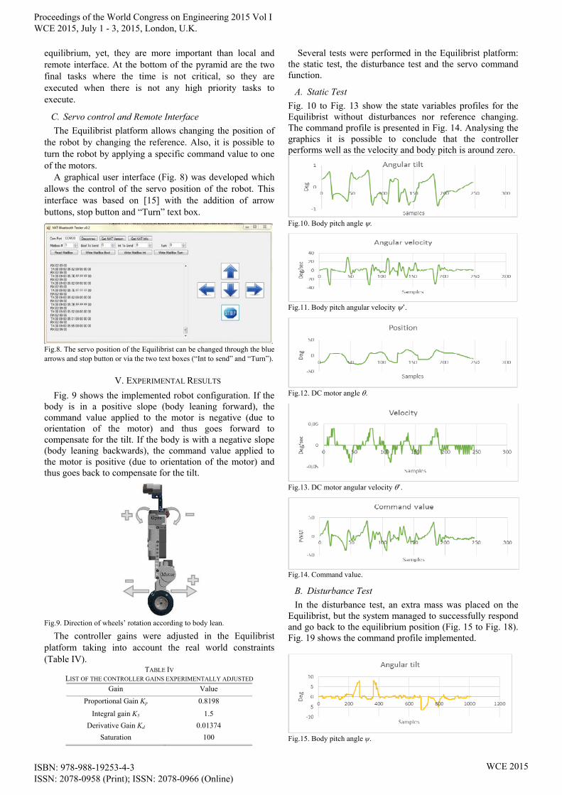
V. EXPERIMENTAL RESULTS
Fig. 9 shows the implemented robot configuration. If the body is in a positive slope (body leaning forward), the command value applied to the motor is negative (due to orientation of the motor) and thus goes forward to compensate for the tilt. If the body is with a negative slope (body leaning backwards), the command value applied to the motor is positive (due to orientation of the motor) and thus goes back to compensate for the tilt.
Fig.9. Direction of wheels’ rotation according to body lean.
The controller gains were adjusted in the Equilibrist platform taking into account the real world constraints (Table IV).
TABLE IV LIST OF THE CONTROLLER GAINS EXPERIMENTALLY ADJUSTED
Gain Value
Proportional Gain Kp 0.8198
Integral gain K5 1.5
Derivative Gain Kd 0.01374
Saturation 100
Several tests were performed in the Equilibrist platform: the static test, the disturbance test and the servo command function.
A. Static Test
Fig. 10 to Fig. 13 show the state variables profiles for the Equilibrist without disturbances nor reference changing. The command profile is presented in Fig. 14. Analysing the graphics it is possible to conclude that the controller performs well as the velocity and body pitch is around zero.
Fig.10. Body pitch angle .
Fig.11. Body pitch angular velocity ’.
Fig.12. DC motor angle .
Fig.13. DC motor angular velocity ’.
Fig.14. Command value.
B. Disturbance Test
In the disturbance test, an extra mass was placed on the Equilibrist, but the system managed to successfully respond and go back to the equilibrium position (Fig. 15 to Fig. 18). Fig. 19 shows the command profile implemented.
Fig.15. Body pitch angle ψ.
Proceedings of the World Congress on Engineering 2015 Vol I WCE 2015, July 1 - 3, 2015, London, U.K.
ISBN: 978-988-19253-4-3 ISSN: 2078-0958 (Print); ISSN: 2078-0966 (Online)
WCE 2015
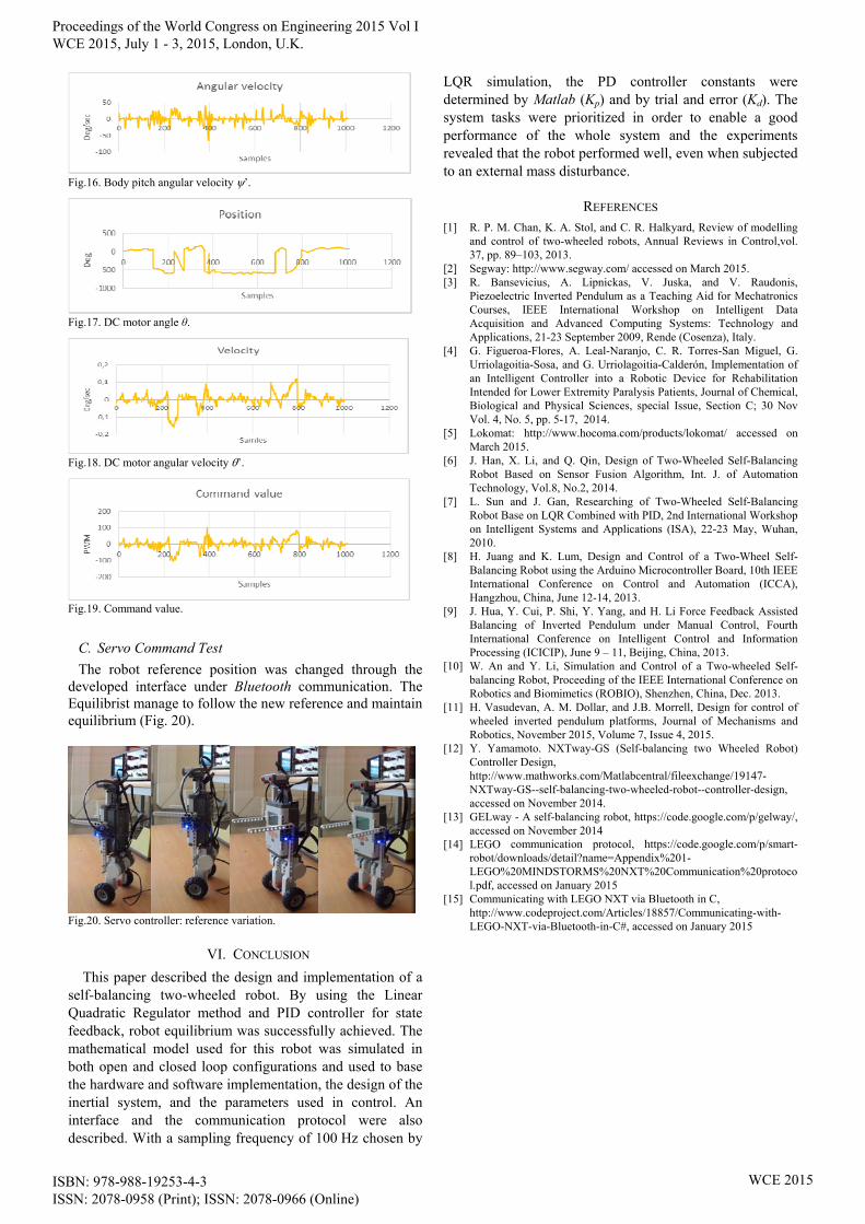
Fig.16. Body pitch angular velocity ’.
Fig.17. DC motor angle θ.
Fig.18. DC motor angular velocity ’.
Fig.19. Command value.
C. Servo Command Test
The robot reference position was changed through the developed interface under Bluetooth communication. The Equilibrist manage to follow the new reference and maintain equilibrium (Fig. 20).
Fig.20. Servo controller: reference variation.
VI. CONCLUSION
This paper described the design and implementation of a self-balancing two-wheeled robot. By using the Linear Quadratic Regulator method and PID controller for state feedback, robot equilibrium was successfully achieved. The mathematical model used for this robot was simulated in both open and closed loop configurations and used to base the hardware and software implementation, the design of the inertial system, and the parameters used in control. An interface and the communication protocol were also described. With a sampling frequency of 100 Hz chosen by
LQR simulation, the PD controller constants were determined by Matlab (Kp) and by trial and error (Kd). The system tasks were prioritized in order to enable a good performance of the whole system and the experiments revealed that the robot performed well, even when subjected to an external mass disturbance.
REFERENCES [1] R. P. M. Chan, K. A. Stol, and C. R. Halkyard, Review of modelling
and control of two-wheeled robots, Annual Reviews in Control,vol. 37, pp. 89–103, 2013.
[2] Segway: http://www.segway.com/ accessed on March 2015. [3] R. Bansevicius, A. Lipnickas, V. Juska, and V. Raudonis,
Piezoelectric Inverted Pendulum as a Teaching Aid for Mechatronics Courses, IEEE International Workshop on Intelligent Data Acquisition and Advanced Computing Systems: Technology and Applications, 21-23 September 2009, Rende (Cosenza), Italy.
[4] G. Figueroa-Flores, A. Leal-Naranjo, C. R. Torres-San Miguel, G. Urriolagoitia-Sosa, and G. Urriolagoitia-Calderón, Implementation of an Intelligent Controller into a Robotic Device for Rehabilitation Intended for Lower Extremity Paralysis Patients, Journal of Chemical, Biological and Physical Sciences, special Issue, Section C; 30 Nov Vol. 4, No. 5, pp. 5-17, 2014.
[5] Lokomat: http://www.hocoma.com/products/lokomat/ accessed on March 2015.
[6] J. Han, X. Li, and Q. Qin, Design of Two-Wheeled Self-Balancing Robot Based on Sensor Fusion Algorithm, Int. J. of Automation Technology, Vol.8, No.2, 2014.
[7] L. Sun and J. Gan, Researching of Two-Wheeled Self-Balancing Robot Base on LQR Combined with PID, 2nd International Workshop on Intelligent Systems and Applications (ISA), 22-23 May, Wuhan, 2010.
[8] H. Juang and K. Lum, Design and Control of a Two-Wheel Self-Balancing Robot using the Arduino Microcontroller Board, 10th IEEE International Conference on Control and Automation (ICCA), Hangzhou, China, June 12-14, 2013.
[9] J. Hua, Y. Cui, P. Shi, Y. Yang, and H. Li Force Feedback Assisted Balancing of Inverted Pendulum under Manual Control, Fourth International Conference on Intelligent Control and Information Processing (ICICIP), June 9 – 11, Beijing, China, 2013.
[10] W. An and Y. Li, Simulation and Control of a Two-wheeled Self-balancing Robot, Proceeding of the IEEE International Conference on Robotics and Biomimetics (ROBIO), Shenzhen, China, Dec. 2013.
[11] H. Vasudevan, A. M. Dollar, and J.B. Morrell, Design for control of wheeled inverted pendulum platforms, Journal of Mechanisms and Robotics, November 2015, Volume 7, Issue 4, 2015.
[12] Y. Yamamoto. NXTway-GS (Self-balancing two Wheeled Robot) Controller Design, http://www.mathworks.com/Matlabcentral/fileexchange/19147-NXTway-GS--self-balancing-two-wheeled-robot--controller-design, accessed on November 2014.
[13] GELway - A self-balancing robot, https://code.google.com/p/gelway/, accessed on November 2014
[14] LEGO communication protocol, https://code.google.com/p/smart-robot/downloads/detail?name=Appendix%201-LEGO%20MINDSTORMS%20NXT%20Communication%20protocol.pdf, accessed on January 2015
[15] Communicating with LEGO NXT via Bluetooth in C, http://www.codeproject.com/Articles/18857/Communicating-with-LEGO-NXT-via-Bluetooth-in-C#, accessed on January 2015
Proceedings of the World Congress on Engineering 2015 Vol I WCE 2015, July 1 - 3, 2015, London, U.K.
ISBN: 978-988-19253-4-3 ISSN: 2078-0958 (Print); ISSN: 2078-0966 (Online)
WCE 2015