Embed Size (px)
Citation preview
CONTROLLING COMPUTER MOUSE
AND KEYBOARD USING A HEAD
MOUNTED ACCELEROMETER
by
Cihat KESER
Engineering Project Report
Yeditepe University
Faculty of Engineering and Architecture
Department of Computer Engineering
2011
CONTROLLING COMPUTER MOUSE
AND KEYBOARD USING A HEAD
MOUNTED ACCELEROMETER
APPROVED BY:
Assist.Prof.Dr. Esin Onbaşıoğlu ……….……………..…………
(Supervisor)
Prof.Dr. Şebnem Baydere …… ……….……………..…………
Assist.Prof.Dr. Gürhan Küçük ………….……………..…………
DATE OF APPROVAL: … /… / 2011
ii
ABSTRACT
CONTROLLING COMPUTER MOUSE AND KEYBOARD USING A HEAD MOUNTED
ACCELEROMETER
This project aims to provide an alternative way of interaction with a computer, for
those who do not prefer or unable to use the traditional human computer interfaces, namely
mouse and keyboard, and this goal is achieved by utilizing an untraditional hardware
instead, the accelerometer.
A head mounted and wireless accelerometer device is used to detect acceleration
caused by head movements of the user in three axes and the provided data are collected by
software on the target computer. Software, then, estimates the pitch and roll tilt in degrees
by analyzing the collected acceleration data. These tilt data are then used to simulate
mouse cursor movement and clicking on target computer. Also, to simulate keyboard
input, software provides an on screen keyboard interface to user where, the cursor
movements are used to navigate through keys. Software, also, has a calibration process
that, determines the system’s current conditions and user’s movement characteristics.
This report presents the overall design decisions and implementation methods and
phases, as well as a through explanation of all layers of the system.
iii
ÖZET
BAŞA MONTE EDİLMİŞ İVME ÖLÇER İLE BİLGİSAYAR FARE VE KLAVYE DENETİMİ
Bu proje fare ve klavye gibi geleneksel insan-bilgisayar-etkileşim donanımlarını
kullanmayı tercih etmeyen veya kullanamayan kişiler için, bilgisayarla alternatif bir
etkileşim yolu sağlamayı amaçlamaktadır, ve bu amaca ulaşmak için gelenek dışı bir
donanım, ivme ölçer, kullanılmaktadır.
Kullanıcının başına monte edilmiş kablosuz bir ivme ölçer ile kullanıcının üç
eksendeki baş hareketlerinin sebep olduğu ivme gözlemlenmekte ve sağlanan veriler,
hedef bilgisayarda çalışmakta olan yazılım tarafından toplanmaktadır. Bu yazılım, daha
sonra, toplanan veriyi inceleyerek, havacılıkta yunuslama ve yuvarlanma olarak bilinen
eksen bazlı eğimleri derece cinsinden hesaplayarak tahmin eder. Hesaplanan eğim bilgileri
kullanılarak da, hedef bilgisayarda fare imleci hareketi ve tıklaması girdileri taklit edilir.
Ek olarak, kullanıcıya sunulan bir ekran klavyesi ile hedef bilgisayarda klavye girdisi taklit
edilmektedir. Yazılım, ayrıca, sistemin bulunduğu koşullardaki durumunu, tepkilerini ve
kullanıcının hareket niteliklerini belirlemek amacıyla bir ayarlama süreci içerir.
Bu raporda, tasarım aşamasında alınan kararlar, uygulama aşamasında kullanılan
yöntem ve aşamalarla birlikte, sistem katmanlarının detaylı bir açıklaması sunulmaktadır.
iv
TABLE OF CONTENTS
ABSTRACT iii
ÖZET iv
LIST OF FIGURES vii
LIST OF TABLES viii
LIST OF SYMBOLS AND ABBREVIATIONS ix
1. INTRODUCTION 1
1.1. Problem Definition 1
1.2. Objective 1
1.3. Overall Concept 2
2. REVIEW OF THE LITERATURE 4
2.1. Head Tracking Solutions4
2.1.1. Solutions Using Generic Sensors 4
2.1.2. Solutions Utilizing TI Chronos 6
2.1.3. Camera Based Head Tracking Solutions 7
2.2. Eye Tracking Solutions 8
2.2.1. Camera Based Eye Tracking Solutions 9
2.2.2. Electrooculogram Signal Based Tracking Solutions 9
3. DESIGN 11
3.1. Hardware 11
3.2. Definition of Tilt Angle 12
3.3. Tilt Angle Analysis Logic 14
3.3.1. Mouse Control 14
3.3.2. Keyboard Control 18
3.4. System Calibration 19
v
4. IMPLEMENTATION 24
4.1. Data Package 25
4.1.1. Communication Package 26
4.1.2. Data Acquisition Package 27
4.1.3. Data Collection Package 28
4.2. Logic Package 29
4.2.1. Keyboard Analyzer 29
4.2.2. Mouse Analyzer 30
4.2.3. Calibration Analyzers 32
4.3. Settings Package 33
4.4. User Interface Package 35
4.4.1. Mode Switch Class 35
4.4.2. Keyboard Interface Package 37
4.4.3. Calibration Interface Package 39
5. TESTING AND EVALUATION 40
5.1. Keyboard Control Test 40
5.2. Mouse Control Test 42
6. CONCLUSION AND FUTURE WORK 44
REFERENCES 45
vi
LIST OF FIGURES
Figure 1.1 Overall concept view of the system 2
Figure 3.1 TI Chronos Watch and the wireless USB Access Point 12
Figure 3.2 Three possible head tilt movements 13
Figure 3.3 Mode switcher user interface with connection status and click mode
indicators 17
Figure 3.4 Specialized keyboard layout solution 19
Figure 3.5 UI for neutral area detection step of calibration process 20
Figure 3.6 UI for usable area detection step of calibration process 21
Figure 3.7 UI for left click characteristics detection step of calibration process 22
Figure 3.8 Sample tilt angle versus time plots for (a) left (b) right clicks 23
Figure 4.1 Layers of the application running on target computer 24
Figure 4.2 TI Chronos communication package format 26
Figure 4.3 Mouse analyzer flow chart 31
Figure 4.4 SettingsPanel UI class shown inside a JOptionPane as message 34
vii
LIST OF TABLES
Table 5.1 Keyboard test results for Stickiness = 0 40
Table 5.2 Keyboard test results for Stickiness = 2 41
Table 5.3 Keyboard test results using normal keyboard 41
Table 5.4 Mouse control test results 43
Table 5.5 Mouse control test results for normal mouse 43
viii

LIST OF SYMBOLS AND ABBREVIATIONS
ACC Acceleration
EOG Electrooculogram
G Standard gravity of Earth
GUI Graphical User Interface
JDK Java Development Kit
JRE Java Runtime Environment
MCU Microcontroller Unit
OSK On Screen Keyboard
TI Chronos Texas Instruments eZ430-Chronos Wireless Development Tool
ix
1. INTRODUCTION
Computers are widely accepted in our daily life in today’s modern era so much
that, there are now arguments over whether internet connection is a basic citizenship
right or not, yet alone computers. More and more services for communication,
entertainment and alike, which use computers as base, are introduced into people’s daily
lives every passing moment. And this fact makes it even more important, whether those
computers themselves are easily accessible by everyone or not.
1
1.1 Problem Definition
There is a need for alternative human computer interface (HCI) channels other than
the traditional mouse and keyboard, to make computers easily accessible by everyone
including disabled people. Ideally, the whole interaction experience based on mouse
cursor and keyboard would be re-designed according to the special needs of a particular
audience but, such a great re-design process is practically not feasible because of the
astronomical amounts of resources (like time and money) that would be required.
1.2. Objective
The main purpose of this project is to provide a feasible alternative HCI channel
for disabled people. Since, there are many different set of requirements from different
user groups, this project mainly focuses on users who are at least able to move their
heads. Also, considering the intended user base’s input (head movement), this project
uses an accelerometer (to be precise, a reference development platform for a
microcontroller unit (MCU), which includes an accelerometer, the TI Chronos) to detect
that input without requiring expensive hardware.
2
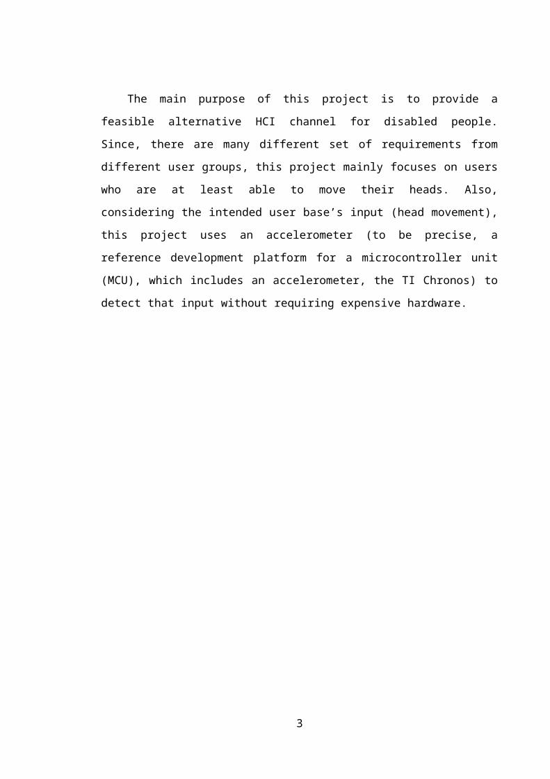
1.3. Overall Concept
This project aims to provide both mouse and keyboard control using the head
movement input. To detect head movement, a TI Chronos is wirelessly connected to the
computer to be controlled (the target computer) and an analyzer application runs on the
target computer to translate head movement to mouse and keyboard events (Figure 1.1).
Figure 1.1 Overall concept view of the system
The analyzer application running on target computer manages the whole system as
well as the connection to TI Chronos and provides the user with two operation modes:
mouse control and keyboard control mode, user interfaces for those operation modes and
a way to switch between them.
To control mouse cursor, user simply tilts his/her head in the direction he/she
wants to move the mouse cursor to. Movement speed of mouse cursor increases as the
user tilts head more and decreases as tilts less. Mouse click events are triggered when the
user quickly tilts head in a direction, which defines the mouse button (left/right) to be
clicked, and returns to normal position.
3

To provide keyboard control, the application provides a customized on screen
keyboard (OSK) to the user. To select keys on this OSK, user tilts his/her head at the
direction of the desired key. To press on a key, user should wait for a customizable
amount of time in the tilted head position, where the desired key is shown as selected on
screen.
For switching between keyboard and mouse control modes, application provides a
button on screen in both modes. Also in the OSK, there are special keys provided for
closing the application and for changing user customizable parameters (showing the
settings panel).
4
2. REVIEW OF THE LITERATURE
There have been several solutions proposed for enabling computer control for
disabled people with spinal cord injuries or paralysis. Considering the target user base,
proposed solutions, most of the time, use the head or eye movements as input.
2.1 Head Tracking Solutions
Head tracking solutions generally utilize gyro (tilt) sensors, accelerometers or
camera(s) to detect head movements, and in the following part, some of such work
(which also inspired this project in one way or another) in literature are presented in
categories representing their system input source.
2.1.1 Solutions Using Generic Sensors
Solutions using generic sensors, that is, gyro sensors or accelerometers generally
share a common hardware design in which they use an input box separate from the
computer. The input sensors are then either wired connected to this input box and
mounted on head or they are included in the box itself and the box is mounted on head.
Gyro sensor using solutions [1] employ either two chips with single axis gyros or a
single chip with two axis sensing gyro, this is required to detect both up, down (vertical
axis) and left, right (horizontal axis) tilts. Accelerometer using solutions [2, 3] generally
employ a single chip three-axis-accelerometer, which provides enough data to calculate
tilt angles in two axes [4]. Also, in accelerometer using solutions, it is possible to
5
increase overall sensor accuracy by using multiple accelerometers which will also
require more complex analysis algorithm [5].
Input box used in the said solutions include a signal processing module which does
the low level, electrical analysis of the sensory input. Signal processing module generally
includes an amplifier to scale the electric potential difference sourced from the sensor, a
low pass filter to filter out unintended movements (like muscle jitters) and an analog to
digital converter module to digitalize the sensor data. Most of the systems additionally
have an MCU inside the input box, whose usage differs depending on the
implementation. Solutions with pure hardware implementations [3], have the keyboard
and mouse control logic coded into MCU and they analyze the sensory input data
according to their logic algorithms which basically translates the input data to mouse
movement or keyboard event. Those type of implementations also have the MCU
simulate an HCI device standard to computer (such as PS/2) and when a control event
occurs, they simply send simulated mouse or keyboard input signals to computer directly
using MCU. Solutions with hardware and software combined implementations [1, 2], use
the MCU only for managing the communication between computer and the sensor
hardware. In such systems, software running on the target computer has the mouse or
keyboard logic code and it analyzes the sensor data according to that logic algorithm.
Software reports to the operating system a software-simulated input event, when an
event is recognized (such as mouse movement).
Mouse movement analysis algorithms of the said systems are some customized
form of basic relative pointing algorithm according to the system specific usable sensor
data range. Relative pointing algorithms works such that, a displacement amount is
calculated according to a custom function using the sensor data as input and this
displacement amount is combined with the current location of the cursor to find the new
location of it. This is a fairly non-complex, practical and good working solution to cursor
movement problem. There are also some solutions, like [6], further building on this idea,
where they apply more complex calculations methods, such as fuzzy logic, to find the
displacement amount in order to improve mouse control efficiency.
A problem arises when the user also wants to simulate mouse clicks because, the
head movements are already used as input to mouse movement control. Solutions to this
6
problem include using the head movements for both movement and click control and
apply complex analysis algorithms or to find a new input device dedicated for mouse
click control. Most systems reviewed in literature prefer the latter solution where hard
switches like sip and puff switches, or touch sensitive switches close to cheek [2] are
used to detect intentional cheek movements, or infrared light sensors are used to detect
eye blinking [1, 3].
Only a limited number of solutions using gyro sensors or accelerometers provide a
way for controlling the keyboard using head movements and even so, a non-head-
movement input such as, blinking is still required. One of those solutions [3], with
keyboard control mode, has a keyboard control logic where, it shows a single character
on screen and allows the user to change shown character by tilting head to left or right.
When the desired character is shown, user blinks to select and type that character. Also,
switching the system’s control mode between keyboard and mouse is done by a long
blink.
2.1.2 Solutions Utilizing TI Chronos
TI Chronos is a relatively new product in the market and thus, the related literature
work about it or using it is very few if none. In the context of computer controlling
systems, TI Chronos generally acts as a wireless accelerometer sensor and nothing more.
Compared to the systems using generic accelerometers or sensors, TI Chronos does all
the work done in the other systems’ input box, all by itself and provides clean, software
workable acceleration (ACC) data. This is made possible by the ACC mode on the TI
Chronos Watch’s original firmware.
Common features of systems utilizing TI Chronos are that, they most often apply a
low pass (or averaging) filter to the input data to compensate for human muscle jitters
and they most often use a high pass (or equivalent) filter to detect sudden intended
movements.7
One of those solutions [7] has the TI Chronos mounted on wrist and provides
mouse cursor movement control by hand movements. It uses a relative pointing
algorithm (as discussed earlier), where the input data determines mouse cursor’s new
position relative to its old position and it simply uses a high pass filter to detect snap like
hand movements and perform a mouse click. There are also solutions [7] providing not
only mouse control but, also joystick control using the same analyzing techniques for
games. One of the most famous examples of such systems is the Wii game console
produced by Nintendo Company. Although, Wii does not use a TI Chronos, it is a great
working commercial example of machine control using accelerometers.
There are also some systems [8] providing overall computer control rather than
individual mouse and keyboard control. They provide an action recording mechanism,
where user records input from real mouse and keyboard, and map every action to a
specific acceleration data pattern. Recorded actions are stored as runnable scripts and
then pattern matching algorithms are used to find mapped patterns in input data from TI
Chronos in real time. The way these kinds of solutions work means that, they require
every action to be pre-recorded and the only way of recording is actually using a real
keyboard and mouse so, they are not really suitable for disabled people.
2.1.3 Camera Based Head Tracking Solutions
There are also head tracking solutions where devices other than gyro sensors or
accelerometers are used for input and the most popular input type among them is the
camera based input, which is also used by most of the commercial and/or professional
systems.
Camera input based head tracking solutions generally either totally rely on
computer vision algorithms to track the user’s head without any attachments [9] or a
special tracking marker is attached to the user’s head or face and then image processing
8
algorithms are used to easily track head movements [10]. On some systems, those special
markers are infrared light reflective surfaces and by applying infrared filters to the
camera input, they break down the complexity of the video analysis algorithm.
Mouse movement control in camera based solutions is generally done by absolute
pointing method, in which every pixel in screen corresponds to a position of the head.
Testimonials from the users of those systems indicate that, absolute pointing method,
when used with camera based solutions, provides a natural feel for navigation.
Mouse click control is implemented either by using wait-to-click algorithms [9],
where user stays still in same position for a time period to simulate a mouse click in that
position, or by using hard switches [10]. Keyboard control is also provided by using the
same mechanism by providing buttons for keyboard on screen. When user stays on a
keyboard button using the mouse cursor for a time period, that key is pressed or when
the user places the mouse cursor on the keyboard key on screen and activates the hard
switch, that key’s press event is simulated to the operating system.
Although camera based solutions claim to provide a more natural feeling of control
compared to tilt sensor based solutions, they have their disadvantages. One of those
disadvantages is the possible interference of environmental conditions, like lighting
conditions. If it is too dark or too bright for the camera to do a proper analysis on the
face or head, these systems will not function properly. Also, since the required resources
for video analysis is too great compared to other solutions, they generally require special
and/or expensive hardware and may not work in the intended way in all computers.
2.2 Eye Tracking
Eye movement tracking is another popular method for providing computer control
to disabled people. Compared to head tracking method, people who cannot move their
head can use the solutions using eye tracking.
9

2.2.1 Camera Based Eye Tracking Solutions
One of the most used and cheapest solutions for eye tracking is using a camera
connected to computer to track user’s eyes. There are many previous works using this
solution [11, 12] and their overall design is generally the same, which is, applying face
detection on the input video stream, detecting eye location, determining eye movement
and then translating detected movement to mouse control. However, they differ greatly
in how the video stream is processed and which methods are used for feature detections,
which are out of scope of this paper.
Methods used for mapping eye movement to mouse movement in camera based
eye tracking systems differ by the implementation and there does not seem to be an
accepted or overall better mapping method in general. There are solutions using pure
absolute mapping, pure relative mapping and speed adaptable relative mapping [12], of
which the last is the most basic and interesting. It is proposed that [12], increasing the
relative mouse movement speed as long as the user keeps his eyes at a movement
direction, provides a more natural, intuitive and effective way of mouse movement
control.
Mouse click control is implemented using the wait to click method in nearly all of
the solutions in this category. And some solutions provide an additional menu, when the
mouse is first clicked, that has the options to right click, double click, drag, release etc.
Also, none of the reviewed solutions provided a specialized way for keyboard control
but, they relied on the on screen keyboard provided by the operating system.
2.2.2 Electrooculogram Signal Based Eye Tracking Solutions
Electrooculogram (EOG) is the name for the very small electrical potential that is
changing relative to the eye’s position and orientation in the head. Detecting EOG
signals is done by placing electrodes on the surface of the face at critical locations, which
depend on the analysis and measurement implementation.
10

General design approach of EOG based eye tracking systems [13, 14] is applying
noise removal (low pass filtering) and amplifying the input EOG signal before feeding it
to the signal processing module. Since eyes are moved unintentionally a lot and they
cannot be dedicated to another aim while successfully providing visual sense to humans,
most of the EOG based systems apply rather complex analysis algorithms compared to
head tracking solutions.
There are solutions providing computer mouse control [13] and solutions providing
control of other utilities (like toy cars) [14]. Independent of the controlled device, EOG
based solutions control mechanisms generally work by moving eye to a direction,
holding it there and then blinking to confirm that the last movement was intentional and
should be interpreted as a command by the system. Systems sometimes modify the order
or amount of required movement to create a more customized experience such as,
blinking twice to confirm, moving eye upward twice to send command up etc. Mouse
click or any other click type commands are also mostly issued by blinking.
11
3. DESIGN
As briefly discussed in Section 1.3, this project uses the head movements of a
person as input to produce simulated mouse and keyboard events on the target computer
and different operational modes are provided to user to achieve this. In this section, the
hardware used in this system and the detailed design of the application running on target
computer are explained
3.1. Hardware
The only hardware needed and used by this project is the TI Chronos and the target
computer itself. Only requirements for the target computer are that it has an available
USB port and it is able to run JRE version minimum 6.
The TI Chronos (Figure 3.1) is basically a smart watch with lots of integrated
sensors. To be more precise, it is a wireless development platform based on Texas
Instruments’ CC430 series MCUs in the form of a wearable sports watch and includes a
96 segment LCD display, a pressure sensor, a temperature sensor and a three-axis
accelerometer. This project is only interested in the accelerometer.
TI Chronos uses the SimpliciTI protocol for wireless communication and it comes
with a wireless USB Access Point (Figure 3.1) to establish the communication between a
computer and the watch. Also, the core of the watch can be dismounted from the frame
and used separately. All of these features, being wireless, light weight and small, made
TI Chronos the best hardware choice for this project and allowed it to be mounted on a
baseball cap to easily mount on head.
12
Figure 3.1 TI Chronos Watch and the wireless USB Access Point
Considering the hardware cost of the system, price of the TI Chronos was less than
50 US$ at the time of writing this document and considering it is the only cost in this
system, it is safe to say that, this system is very efficient cost-wise compared to similar
commercial products. 1
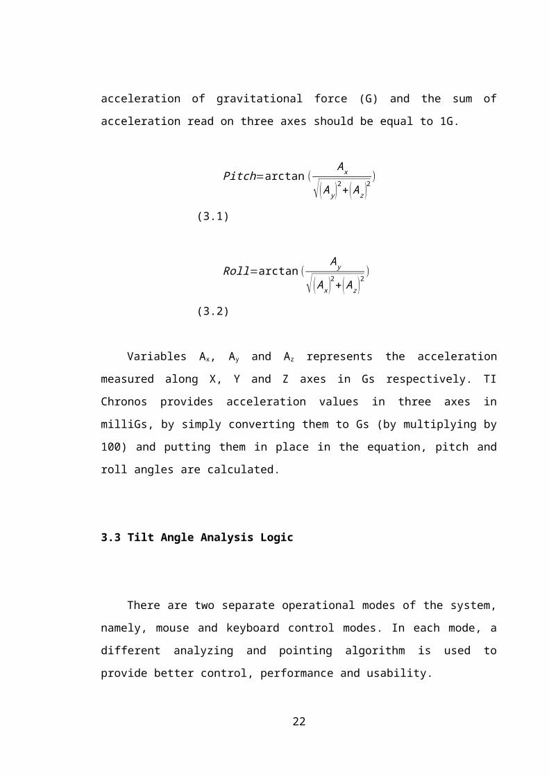
3.2 Definition of Tilt Angle
This system uses head movements as the sole input method, more precisely head’s
tilt angles are used. Head tilt angles define how much the head is rotated along an axis.
There are three possible head tilt movements, which are shown in Figure 3.2, and they
are defined as:
(i) Pitch, the vertical head rotation movement (as in looking up or down)
1 Prices of commercial head or eye tracking devices designed for disabled people range from 150 US$ to 5,000 US$. <http://www.enablemart.com/Catalog/Head-Eye-Tracking>
13
(ii) Roll, the head rotation that occurs when tilting head towards the shoulders
(iii) Yaw, the horizontal head rotation movement (as in looking to left or right).
Figure 3.2 Three possible head tilt movements
It is possible to detect and measure an object’s roll and pitch movements by using a
single three-axis-accelerometer mounted on the object [4, 5]. Assuming a non-moving
object, if the object is rotated along any of its axes, an accelerometer mounted on it will
read portions of the gravitational force depending on the rotation angle. The object being
a person’s head in this case, the head tilt movements, pitch and roll, can be easily
measured. It is also possible to measure yaw angle too using two accelerometers but, this
project is only interested in pitch and roll angles. To translate the acceleration values
obtained by the three-axis-accelerometer to pitch (Equation 3.1) and roll (Equation 3.2)
angles, trigonometric equations are used. These equations are based on the fact that, a
non-moving object will only experience the acceleration of gravitational force (G) and
the sum of acceleration read on three axes should be equal to 1G.
Pitch=arctan (Ax
√ ( Ay )2+( A z )2) (3.1)
Roll=arctan (A y
√ ( Ax )2+ (A z )2) (3.2)
14

Variables Ax, Ay and Az represents the acceleration measured along X, Y and Z
axes in Gs respectively. TI Chronos provides acceleration values in three axes in milliGs,
by simply converting them to Gs (by multiplying by 100) and putting them in place in
the equation, pitch and roll angles are calculated.
3.3 Tilt Angle Analysis Logic
There are two separate operational modes of the system, namely, mouse and
keyboard control modes. In each mode, a different analyzing and pointing algorithm is
used to provide better control, performance and usability.
3.3.1 Mouse Control
The aim of this project is to use only the head movements to control the mouse and
keyboard. To provide mouse movement and click control without using any hard
switches, there are two types of analysis done simultaneously on the tilt angle data:
- Movement analysis
- Click analysis.
For the movement analysis, it is needed to somehow translate the tilt angle data to
displacement of mouse cursor that is calculating new cursor position. There are two main
methods when calculating the new mouse cursor position:
(i) Absolute mapping in which every tilt angle corresponds to a position on screen
(ii) Relative mapping in which every tilt angle corresponds to a cursor
displacement amount (step size) and this amount is summed by the coordinates of the
cursor’s old position, to calculate new position.
In this project, a simple speed adaptable version of second method is used. The
reason for this is when the absolute mapping method is used, the area to be covered by
15
the tilt range, the whole screen, is too great compared to typical usable tilt range with
human heads and the precision of the tilt degree measurements are not good enough to
compensate. For example, most computer screens nowadays has the minimum resolution
of 800x600 pixels and a healthy human can tilt his/her head left/right by approximately
30 degrees maximum. This means that, we have a 60 degree total usable tilt range
horizontally and a screen area of 800 pixels to cover horizontally, which amounts to
(800/60) roughly 13 pixels per degree. This means if (i) is used, each one-degree
increase in tilt angle will move the mouse cursor 13 pixels from its old position. This
makes a very inaccurate and imprecise pointing system even in the best case. But if the
relative mapping method is used instead, the precision and accuracy of the mouse cursor
can be adjusted as desired. For example, if the step size is set to one pixel, the mouse
cursor will shift one pixel away from its old position in the direction of the head tilt. In
the basic relative mapping algorithm, this step size is independent of the tilt angle and
constant but, in this project, it is proposed to use a variable step size based on tilt angle.
In the proposed method, step size is directly proportional to the tilt degree. To calculate
the current value of the variable size, the ratio of current tilt angle to the maximum
possible tilt angle (detected by the calibration process) is calculated and then a user
selectable maximum mouse speed value is multiplied by this ratio. During the
development tests, it was observed that the speed adaptable relative mapping method
provided a more intuitive and precise way of control compared to both simple relative
mapping and absolute mapping. Also, it should be noted that by using different methods
to calculate the current value of variable step size, improvements can be done in the
mouse movement control.
For click analysis, as explained in Section 2.1, there are three common methods
used:
(i) Using hard switches to detect non-head-movement input, as in [1, 2, 3]
(ii) Applying a high pass filter to input data to detect sudden movements, as in [7]
(iii) Using a wait-to-click algorithm, where user waits for a specified amount of
time to directly trigger a click, as in [9].
In this project, a unique combination of (iii) and a click pattern matching algorithm
is used because, (i) is against the aim of this project as it uses extra hardware and (iii)
16

alone would not be fit for this project since, the method used for mouse movement
control is relative mapping. In relative mapping method, user waits in neutral position to
stop movement and rest, and if only (iii) is used, system will keep sending mouse clicks
while the user is simply resting and does not want to move or click the mouse. Also, test
of the systems using (ii) shows there are too much false positive detections by the system
and it would be too complicated to set up a high pass filter that is customized for each
user’s characteristics which can properly differentiate between not-so-sudden click
movements and non-click cursor movements.
When the user wants to make a mouse click, a sudden click-like movement at the
direction of the desired mouse button is required (i.e. left tilt for left click, right tilt for
right click). Click analysis is done using the same methods discussed in the click
characteristics detection step of calibration process, in which, the algorithm searches for
the extreme point and the two neighboring neutral points, calculates the click height and
duration and compares them to the minimum threshold values obtained during
calibration. If the analyzed values are greater than the minimum threshold values set in
calibration process, a mouse click event is sent to the operating system.
Using same input source, the head tilt angle data, for both click and movement
analysis also has its disadvantages like when the user wants to make a mouse click and
tilts his/her head accordingly, mouse click will be detected by the system when the user
returns to neutral position but, the system will also convert the tilt data obtained during
click operation to mouse movements. That is, the mouse will both move and click at the
same time and this will cause clicks at unwanted positions, not to mention that the
system will be basically unusable.
To overcome the explained disadvantage of using head tilt angles data for both
mouse movement and click, this project proposes a new analysis method which
combines relative position mapping and wait-to-click methods. In this new method, the
speed adaptable relative mapping method is used as it is described earlier but, an
addition to the click analysis method is made, in which user needs to wait for a specified
amount of time (e.g. one second) in neutral zone to put system in click mode. Click
analysis described earlier is only applied if the system is currently in click mode and also
17
movement analysis is stopped during click mode. When the system enters the click mode
two things happen: first, a countdown timer is started and second, with every new
coming data, all collected data is analyzed for clicks. System exits click mode when the
countdown timer times out or if any click is detected before timeout. A status indicator
area in the mode switcher user interface (show in Figure 3.2) changes color according to
whether the system is currently in click mode (blue) or not (gray).
The proposed combined mouse control method is analogous to the normal mouse
operation habits where, people move the cursor to the position they want to click, then
they stop on that position for a very short time and then they click on the mouse button.
Using this system, this scenario can be translated as following: user tilts head to move
the cursor to the desired position, then the user waits in neutral position to enter click
mode and then user makes a click movement using his/her head. The only down side of
this solution is the added delay when the user is resting head in neutral zone but does not
want to click, which puts the system into click mode continuously and when the user
wants to move mouse cursor again, there will be a delay before movement begins caused
by the need for waiting the timeout counter.
Initially system is in mouse control mode and to switch to keyboard control mode,
user needs to click on a button on screen. This button is labeled “Show Keyboard” and
located in the mode switcher user interface shown in Figure 3.2, along with the
connection status indicator, which changes color based on whether a TI Chronos is
connected and usable with the system (green) or not (red).
Figure 3.3 Mode switcher user interface with connection status and click mode indicators
3.3.2 Keyboard Control
18

There are two common keyboard solutions used in head tracking computer control
systems:
(i) Single character navigation method, as used in [3], in which a single character is
shown on the text entry field and user changes the shown character one by one. To select
a character to be typed, user waits for a specified amount of time or extra hard switches
are used for detecting eye blinking or similar movements.
(ii) On screen keyboard (OSK) method, as used in this project, in which a user is
presented with an OSK where all the characters are shown at once and user selects the
desired character among them using a keyboard cursor. To type that character, user
simply waits with the cursor on the character for specified amount of time.
When this system is in keyboard control mode, a specially designed on screen
keyboard is shown and the head tilt movements act as an absolute pointing device.
Navigation on keyboard is achieved by mapping every key shown on the OSK to a tilt
degree range and mapping a special resting zone on keyboard to the neutral tilt range.
Meaning of “navigating on keyboard” in this project’s context is to move a distinctive
visual keyboard cursor (and also the mouse cursor) on to the currently selected key. To
press on the currently selected key, user needs to wait on that key for a threshold time
that is, he/she should keep his/her tilted in the same degree range of the corresponding
key for a limited time. The disadvantage of using absolute pointing for mouse control
was discussed earlier but, for the keyboard application, absolute pointing is more
favorable because of the exactly same reasons. For example, the OSK used by this
system has 11x7 keys and using the same example of 30 degrees of available head tilt to
every direction, (60/11) roughly six degrees head tilting is needed to navigate over a
single key. This amount of key to tilt degree resolution provides accurate enough results
and comfortable operation for the OSK designed in this project. OSK also provides
special keys for returning to mouse control mode (labeled “Hide Keyboard”), for exiting
the program and for opening the program settings dialog (see Figure 3.3).
19

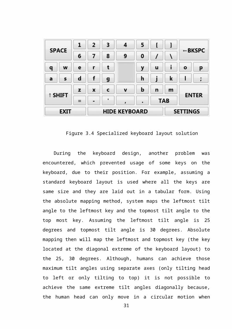
Figure 3.4 Specialized keyboard layout solution
During the keyboard design, another problem was encountered, which prevented
usage of some keys on the keyboard, due to their position. For example, assuming a
standard keyboard layout is used where all the keys are same size and they are laid out in
a tabular form. Using the absolute mapping method, system maps the leftmost tilt angle
to the leftmost key and the topmost tilt angle to the top most key. Assuming the leftmost
tilt angle is 25 degrees and topmost tilt angle is 30 degrees. Absolute mapping then will
map the leftmost and topmost key (the key located at the diagonal extreme of the
keyboard layout) to the 25, 30 degrees. Although, humans can achieve those maximum
tilt angles using separate axes (only tilting head to left or only tilting to top) it is not
possible to achieve the same extreme tilt angles diagonally because, the human head can
only move in a circular motion when looked from top. Because of this, the user can
never reach the diagonal extreme keys. One way of solving this problem is making the
keyboard layout same as the motion limit shape of the head, that is making a circular
keyboard. In addition to the complex implementation requirements that solution would
need, it would also consume too much screen space. Therefore, this project proposes a
specialized keyboard layout, shown in Figure 3.3, which is rectangular shaped and the
layout is in tabular form again but, the diagonal keys use double the space of other keys.
Tests made using this solution proved that it is indeed an efficient solution and is also
easy to use and easy to implement.
20
3.4 System Calibration
Before operating in mouse and keyboard control modes, the system first requires a
calibration, to analyze data more effectively in a per user basis. This type of calibration
is also used by many of the solutions reviewed in head tracking systems. System can
remember the user specific calibration data if the user chooses the option and if not it
needs to be re-calibrated at every system start. Calibration process consists of four steps:
neutral area detection, usable range detection, left click characteristics detection and right
click characteristics detection. User is guided through these steps by an interactive GUI
and no other device than the TI Chronos is required.
Neutral area detection step in calibration process requests the user to stand still in
neutral position for a specified amount of time (Figure 3.5), which was found to be
ideally five seconds. While the user is in neutral position, system collects tilt angle data
and finds the maximum and minimum angles in each axis. These found boundary angles
represent the dead zone of the input, that is, the input range the system should ignore.
Figure 3.5 UI for neutral area detection step of calibration process
21
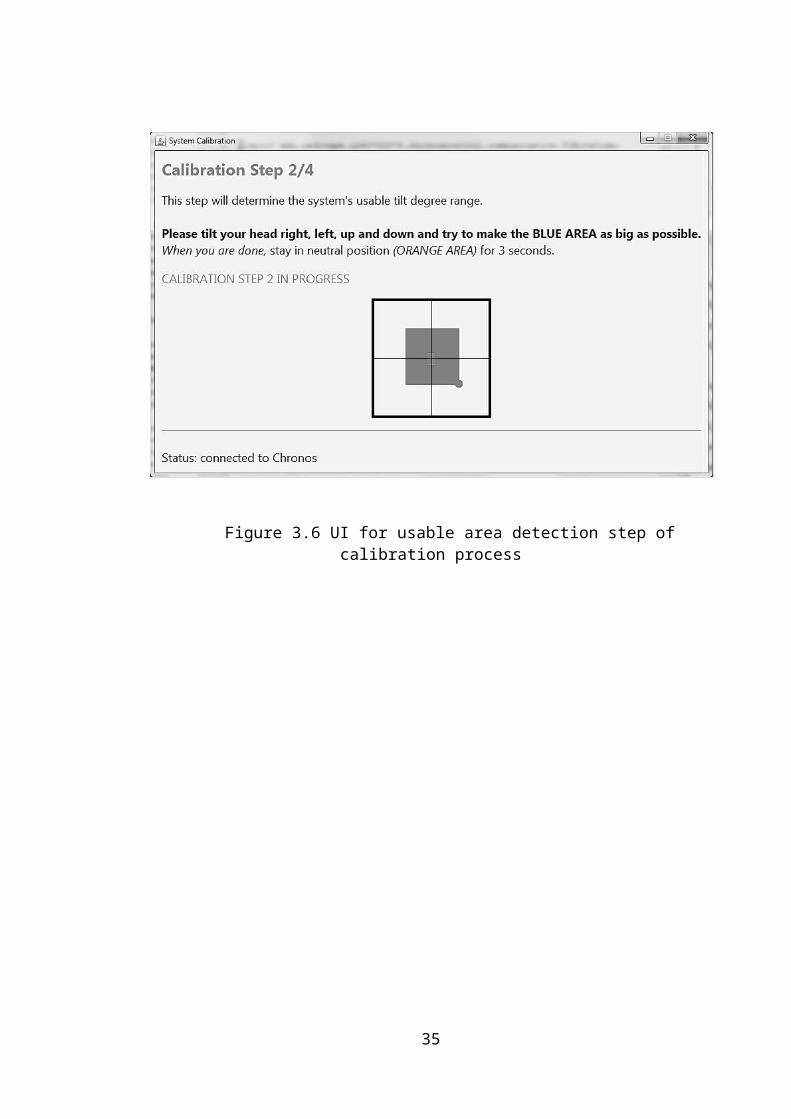
Usable range detection step in calibration process requests the user to tilt his/her
head as much as possible in a comfortable manner (Figure 3.6). Again the tilt angle data
during this step is collected and then analyzed to find maximum and minimum angles in
each axis. Found extreme angle values are recorded as the usable tilt range boundaries.
There are two click characteristics detection steps in calibration process, for left
and right click separately, which involve requesting the user to make a click like
movement in the direction specified, that is the user should, in a fast manner, tilt his/her
head in the specified direction and then return to neutral position. The user interface for
left click characteristics detection is shown in Figure 3.7. System collects the tilt angle
data during this step and then applies click analysis on it. A sample tilt angle data versus
time plot is shown in Figure 3.1, for left and right click.
Figure 3.6 UI for usable area detection step of calibration process
22
Figure 3.7 UI for left click characteristics detection step of calibration process
Click characteristics analysis involves finding the extreme minimum maximum
point in the collected data and then finding the two points in neutral area that are closest
to the extreme point. These three points together form a triangle like shape and the click
analysis algorithm used by this project is based on the properties of that shape. The
extreme point is recorded as the minimum height of click and the distance between two
neutral points is recorded as the minimum click duration. These two characteristic
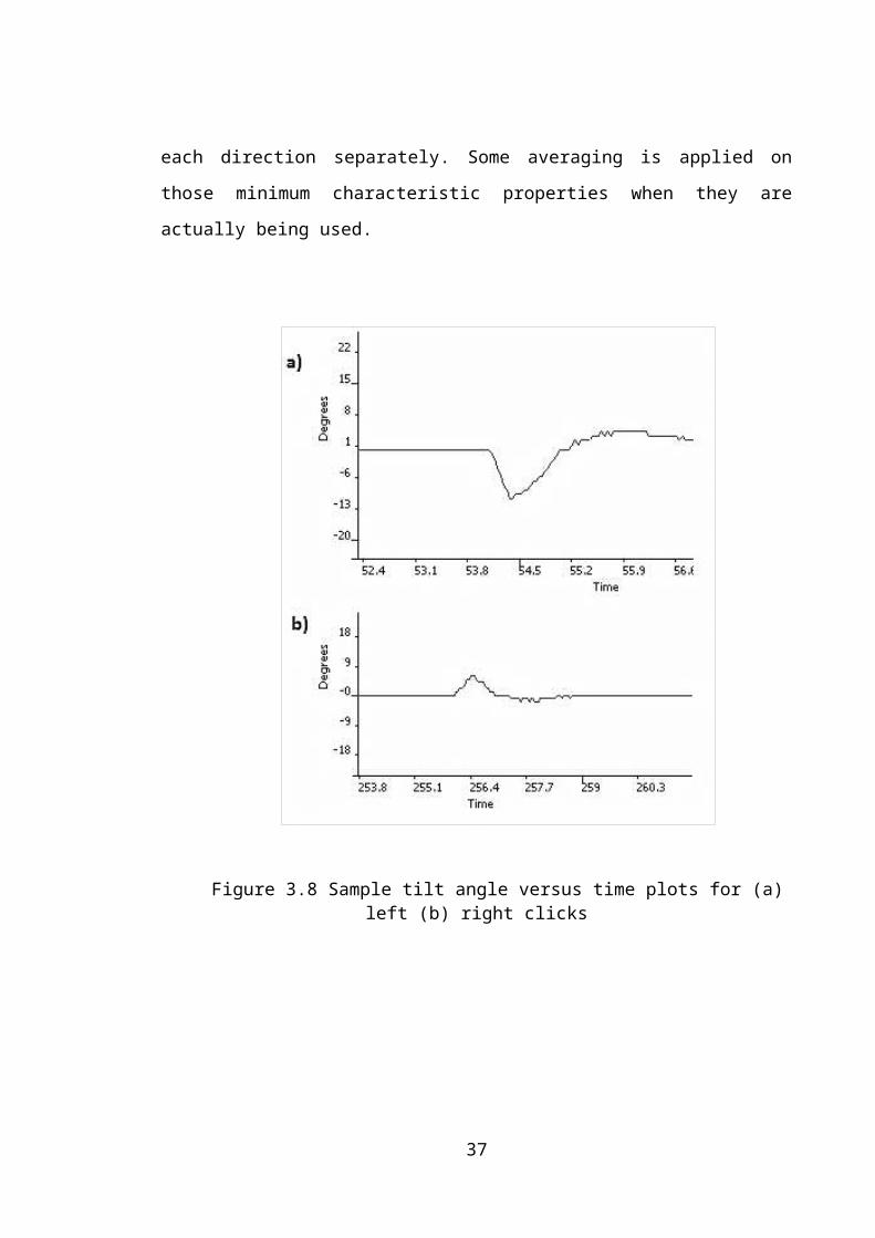
properties are detected and recorded for each direction separately. Some averaging is
applied on those minimum characteristic properties when they are actually being used.
23

Figure 3.8 Sample tilt angle versus time plots for (a) left (b) right clicks
24
4. IMPLEMENTATION
As described in earlier sections, this system collects and analyzes the acceleration
data obtained from TI Chronos using a custom tailored Java application. This application
runs on a Java Runtime Environment (JRE) on the target computer and it was designed
in three layers (Figure 4.1): data layer, logic layer and user interface layer. Each layer is
implemented as a Java package under the main package domain, which is
“edu.yeditepe.u260702073.chronoscontrol” for this project, and sub-packages are used
where necessary.
Figure 4.1 Layers of the application running on target computer
25
Data LayerManage connection between Chronos and computerPoll Chronos For ACC DataKeep a collection of received ACC data
Logic LayerChoose an analyzer depending on operation mode (keyboard, mouse or calibration)Apply the analyzer on the collected dataPass any detected input events (output of analyzer) to the Operating System (OS)
User Interface LayerManage and update the mode switcher, OSK and calibration interfaces
NetBeans Integrated Development Environment (IDE) version 6.9.1, on a
computer with Windows 7 OS, was used as the main development tool throughout the
project, along with the Java Development Kit Standard Edition (JDK SE) version 1.6.21
as the development base. This project uses SwingWorker utility class extensively inside
GUI related code and since SwingWorker class was included in the Java Standard
Edition starting from the version 1.6, the minimum required JRE version for this project
is also 1.6.
4.1. Data Package
Data package, consisting of three sub packages, is the implementation of the base
layer of the application, data layer, and it is responsible for overall data management. Its’
responsibilities also includes establishing the connection to TI Chronos, polling it for
new acceleration data within defined time intervals and keeping a collection of old data
with a limited size. This history collection of ACC data is required later for analysis by
the other layers. Data package uses the Java package name
“edu.yeditepe.u260702073.chronoscontrol.data”.
Data package also includes four object classes to better organize the data flow
inside program. These are: AccelerationData, TiltData, AxisData and TiltAxisData.
AccelerationData and TiltData classes are for single data point objects that contain
instantaneous data for all three axes. AccelerationData class is for representing
acceleration values in three axes in milliGs, TiltData class is for representing tilt angle
values for pitch and roll in degrees. AxisData and TiltAxisData classes are for
representing a single dimension and they contain an ArrayList object where the
acceleration and tilt degree history values are stored. AxisData and TiltAxisData classes
also store the usable and unusable range boundaries obtained during calibration process
and they have methods to determine if a given value is within those boundaries. These
classes also have methods, which aid in analysis and calibration processes, to determine
the maximum and minimum points in the history and to find points in unusable area
nearest to a given point in history.
26
4.1.1. Communication Package
The Wireless USB-AP (USB Access Point) provided with the TI Chronos provides
a virtual serial port for communication when plugged in to a computer and
communication is done using operation codes in hex format [15]. Unfortunately, Java
language, by default, does not have the ability to use serial or parallel ports of a
computer directly. For this reason, a third party library is used in this project, a popular
library in the Java world for accessing serial and parallel ports, the RXTX [16].
Implementation of communication was inspired and built on top of the basic TI
Chronos communication codes provided in the CAGE project [8]. Under the
communication package are five classes: ChronosComm, CommPacket, TIByteCode and
Usbmodem.
Communication with USB-AP is done using byte packages with a special syntax
(Figure 4.2). These byte packages contain two-byte operation code (OPCODE), variable
length packet payload and the one-byte packet length. TIByteCode class contains the
byte to command mappings for all byte operation codes supported by TI Chronos.
CommPacket class contains some of the most frequently used byte packages in pre-
calculated byte array form so that, they are not reconstructed every time they are used.
(FF=1111 1111)1 Byte Packet Start Indicator
2-BytesOPCODE
1-BytePacket Length
N-BytesPayload
Figure 4.2 TI Chronos communication packet format
Usbmodem class provides methods to open and close serial port, query USB-AP
status and poll USB-AP for ACC data. Open and close serial port methods use the
RXTX library to setup a communication channel with a serial port and obtain the input
and output data streams associated with the port. Open and close methods also send the
OPCODEs to start and stop USB-AP after setting up the serial port. Methods for status
querying and ACC data polling, simply writes the appropriate byte package from
27
CommPacket class to the output stream of the opened port, then they analyze the
response byte package and return the payload section inside it.
ChronosComm class basically acts a wrapper to the Usbmodem class and provides
a higher level of control. ChronosComm class provides methods to connect, disconnect,
query USB-AP status and poll for ACC data. Connect and disconnect methods
respectively call the open and close methods of the Usbmodem and they also, keep the
connection status in an internal variable. This internal variable indicates whether they
system is connected to the USB-AP at the moment, and is used by other methods.
Method for querying USB-AP status, calls the corresponding method in Usbmodem class
and returns the result if the system is currently connected to USB-AP, else it returns an
error code. ACC data poll method calls the corresponding method in Usbmodem class
and converts the byte values to milliGs. This conversion is a trivial one because, the byte
data obtained from TI Chronos represent the acceleration values using 2’s complement
form, which is same as the Java’s byte primitive implementation so, simply typecasting
the obtained values to integer (int) primitive, the correct result is obtained. Also, TI
Chronos documents state that the acceleration value byte resolution is 18 milliGs.
Therefore, if the int values are multiplied by 18, the result is acceleration value in milliG
form. Using the translated values, method creates an AccelerationData object and returns
it.
4.1.2. Data Acquisition Package
Data acquisition package contains a single class, AccelerometerDataAcquirer,
which implements Runnable interface and extends Observable class, both of which
provided under Java’s “java.util” domain. Initializer of this class creates a
ChronosComm object and calls the connect method of it and that object is used in the
rest of the methods. In the run method, which is required by the implementation of
Runnable interface, ACC data polling method of the ChronosComm object created in
initializer is called and all observers are notified of the returned data.
28
4.1.3. Data Collection Package
Data collection package is made up of only the AccelerometerDataCollector class,
which implements the Observer interface and extends the Observable class. This class
holds references to the three AxisData objects for the three axis acceleration values
obtained from TI Chronos, another three AxisData objects for the smoothened
acceleration values and two TiltAxisData objects for the tilt angle values calculated from
the smoothened acceleration values. AccelerometerDataCollector class observes the
AccelerometerDataAcquirer class and when it receives an update notification, it does
four things:
(i) Add the raw acceleration data to the history ArrayLists of appropriate AxisData
objects
(ii) Apply weighted moving average filter on the values in history plus the new
incoming data. This is done using the equation 4.1 for each axis (x, y, z) and has the
effect of smoothing input signal. Then, the smoothened new data is added to the
appropriate AxisData objects. In the equation 4.1, (T-1) is the index of the last data in the
history ArrayList and AT represents the new data which is not yet added to the history
and n is the length of the filter. In a sense, n is the level of desired smoothness and its
value can be changed in this application using the properties file. Since rest of the
calculations and analyses based on the smoothened values, changing n heavily affects the
overall user experience.
AT=(n× AT )+( (n−1 )× AT−1 )+…+AT−N+1
n×(n+1)2
(4.1)
(iii) Calculate pitch and roll angles using equations 3.1 and 3.2 then, add the
resulting values to the history of appropriate TiltAxisData object
(iv) AccelerometerDataCollector also keeps a reference to the currently used
analyzer class (from the logic layer) and it is notified of the incoming ACC data.
29
4.2 Logic Package
Logic package is the implementation of the middle layer of the application, the
logic layer, and it is responsible for analyzing the obtained ACC data according to
current operation mode. It also passes any detected events to the operating system and/or
user interface accordingly. Logic package uses the Java package name
“edu.yeditepe.u260702073.chronoscontrol.logic”.
4.2.1 Keyboard Analyzer
While the system is in keyboard control mode, the current analyzer reference in the
AccelerometerDataCollector is set to an instance of the KeyboardAnalyzer class. As new
ACC data become available this class is notified and then the position of the keyboard
cursor according to current tilt degree is calculated and reported to the user interface
layer.
KeyboardAnalyzer class requires the column and row count of the OSK to be
supplied with its initializer and these values are stored as class properties. When a
notification of new data is received, the cell to be selected in the OSK (and therefore the
button residing in cell) is calculated by:
(i) Calculate the row column index of center cell by dividing column count and
row count by two. Center cell’s index is increased by one if the corresponding count is
even number.
(ii) Calculate ratio of the current tilt angle to the maximum usable tilt angle and
multiply the center cell index by this ratio. This operation simply maps the usable range
to the keyboard’s row and columns. The result is the distance of the cell to be selected
from the center cell. Then sum the result’s row with the row count and result’s column
with the column count to find the absolute index of selected key in OSK. For example, if
the current pitch and roll are (0, 0) degrees, that is they are in neutral area, then exactly
the center cell will be selected, which is the neutral area of the OSK. It should be noted
30
that, it is possible to differentiate between left or down tilt and right or up tilt using the
sign of the pitch or roll value. For example, assuming the sign is negative for left tilt, if
the user tilts head left, the calculated horizontal distance will be negative and when it is
summed up with the column count, the absolute index will be positive but smaller than
the index of center cell.
(iii) To avoid jitters (unwanted changes in selected key), KeyboardAnalyzer class
keeps a history of recently selected keys’ indexes. If the last N indexes in the history is
same as the current one, the current index is reported to the OSK UI layer else, the
previously selected key’s index is reported, that is the index is not changed. The variable
N is changeable by user as it heavily affects the user experience for keyboard.
4.2.2 Mouse Analyzer
As explained earlier in the design section, mouse control analysis is done using a
new proposed method. In this method, movement analysis is done using a simple speed
adaptable relative mapping algorithm and click analysis is only done if the system is in
click mode. To put system into click mode, tilt angles should be within the neutral range
boundaries for a period of time and to make a click while in click mode, user needs to tilt
his/head left or right and tilt back to neutral position quickly, which produces a triangle
like shape in the input signal. Implementation of this analysis method is done in the
MouseAnalyzer class, whose flow chart is shown in Figure 4.3.
When MouseAnalyzer class is notified for new tilt data by the
AccelerometerDataCollector class, firstly application checks if it is in click mode or not.
If the application is in click mode, it tries to detect a click movement in the tilt angle
history and if a click is detected, it is passed to the operating system. Click detection is
done using the following steps:
(i) Index of the positive peak and negative peak in the horizontal tilt input signal
(history) is found using the provided method by the TiltAxisData class. If no peaks are
found analysis ends. If the positive peak value is dominant (greater than) negative peak
value, analysis is done for right click, else analysis is done for left click. The dominant
31

peak value is compared to minimum click height obtained during the calibration process
and if it is less than the minimum height analysis ends, else the analysis continues.
(ii) Two tilt angles in neutral area are searched, such that, one of them is before the
dominant peak point and the other is after the dominant peak point. Again, the method
provided by TiltAxisData class is used for this purpose.
(iii) The distance between the two neutral points are calculated and compared
against the minimum click distance obtained in calibration process. If the distance is
greater than the minimum with a tolerance value, a new click event is reported to the
operating system and the application is set out of the click mode. Sending the event to
OS is done using the Java Robot class. This tolerance value is configurable using the
properties file. Also, if a click is detected, new minimum click height and distance values
are calculated by averaging the old minimum values and currently detected values. This
provides dynamically changing threshold values to compensate for any errors made
during the calibration analysis.
Figure 4.3 Mouse analyzer flow chart
32
If click mode timeout occurs during any of these steps, application gets out of click
mode. When new tilt data is received while the system is not in click mode, following
steps are done in order:
(i) Check history tilt data to determine if a click is possible, that is if the system
should get into click mode. This is determined by whether the last N tilt angle values in
history are in neutral area, if they are, system is put into click mode and waits new tilt
data. Also, UI layer is notified that the click mode is on and the click mode timeout timer
is started, where timer is set to the minimum click time value plus four times the click
time tolerance (click time tolerance is configurable using properties file). If a click is not
possible, analysis continues to next step.
(ii) Received tilt data is converted to mouse movement, and the created mouse
cursor movement event is sent to operating system using Java Robot class. Conversion is
done by finding cursor displacement value in pixels and adding it to the current position
of cursor. Cursor displacement is calculated by multiplying, the ratio of received tilt
angle to the usable tilt range, with the maximum mouse cursor speed (which is
changeable by the user from the settings panel).
4.2.3 Calibration Analyzers
There are three special analyzers used only by the calibration process neutral area
analyzer, usable area analyzer and click analyzer. They are, respectively, implemented in
the CalibrationDeadzoneAnalyzer, CalibrationUsableAreaAnalyzer and
CalibrationClickAnalyzer classes. During calibration process, the current analyzer
property of the AccelerationDataCollector class is set one of the calibration analyzer
classes and the calibration UI classes directly use the methods of the analyzers.
CalibrationDeadzoneAnalyzer class is used in the neutral area detection step of
calibration process. It contains only one method for analyzing collected data and that
method is called by the calibration UI when the countdown for the calibration step ends.
When the method is called, it sets the dead zone boundary properties of the TiltAxisData
objects. These boundaries are found by using the max and min methods, provided by the
33
Java Collections class, on the tilt data history in TiltAxisData objects. The history is
cleared after this method is called so that, the next calibration step works correctly.
CalibrationUsableAreaAnalyzer class has the same implementation and usage for
the method analyzing collected data as the CalibrationDeadzoneAnalyzer class. In
addition, every time AccelerationDataCollector notifies it for new tilt data, it checks if
the tilt angles are in neutral zone and if so, increases a counter. It also has a method for
determining if the user is active, this method is used by the calibration UI to decide
whether it should end the usable area detection step. This method is called by calibration
UI class every three seconds and when called it checks whether most of the data came in
the last time span was in neutral zone by using the neutral point counter and returns the
result of this comparison. If the result is false, counter is reset so it will correctly count
the points for the next time span.
CalibrationClickAnalyzer has two methods for analyzing the history for right and
left click movement. These methods are called by calibration UI in every second and
they do the same analysis done in the MouseAnalyzer class. Except that, they don’t have
the click mode instead, they are always waiting for a click. If a click movement is
detected, height and distance properties of the click are calculated and saved in the
properties file. Click characteristics detection steps of the calibration UI does not
advance steps until they receive a click movement detected result from this class.
4.3 Settings Package
Settings package is used to achieve centered management and persistence of
configurable parameters in the application. It uses the Java package name
“edu.yeditepe.u260702073.chronoscontrol.settings” and includes three classes:
Parameters, SettingsPanel and SettingsController.
Parameters class provides static and volatile (thread safe) access to all configurable
parameters in the application. It also has methods to save all those parameters to an
34
external properties file and to load them from the external properties file. This external
file is named “ChronosControl.properties” and load and save operations are done using
the Java Properties class to follow standards.
SettingsPanel class contains the UI design for the settings panel presented to the
user and it extends the Swing’s JPanel class. Only the mostly used and non-technical
parameters are presented in this panel to preserve simplicity, these parameters are:
maximum mouse cursor speed, keyboard stickiness factor, keyboard wait to click time
and whether remember or not user characteristics. There is also an experimental setting
for changing the control mode between head mounted and wrist mounted.
SettingsController class acts as the data controller for SettingsPanel UI class and it
has a single method to show the settings panel to user. This method loads the parameters
from Parameters class to a SettingsPanel object and shows a JOptionPane using the
SettingsPanel object as the message (Figure 4.4). After the dialog is closed,
SettingsController class checks the dialog result and saves the changed values back to
Parameters class if the dialog was closed using the OK option.
Figure 4.4 SettingsPanel UI class shown inside a JOptionPane as message
35
4.4 User Interface Package
User interface (UI) package is the implementation of the top layer of the
application, the UI layer, and it is responsible for providing and managing the GUI for
the application. It uses the Java package name
“edu.yeditepe.u260702073.chronoscontrol.gui”. In mouse control mode, user interface
layer provides a single button to the user to switch to the keyboard control mode, along
with system status information. User interface layer is also responsible for switching
between mouse and keyboard control modes and reporting this switch to the interested
layers (i.e. the logic layer so that, it can analyze correctly depending on the operation
mode). In keyboard control mode, user interface layer shows an OSK to the user and a
custom keyboard cursor. User interface layer updates the OSK according to the position
data received from logic layer and then analyzes whether user waited on the key enough
to press it. UI package consists of two sub packages and a class as explained in the
following sections.
4.4.1 Mode Switch Class
The mode switching UI shown previously in Figure 3.3 is implemented using the
ModeSwitchFrame class, which implements the Java Observer interface and extends the
Swing’s JFrame class and it contains the UI design and event handlers for the mode
switch interface. As previously shown (Figure 3.3), this interface includes the connection
status indicator area, mode switch button and the click mode indicator area.
ModeSwitchFrame class observes the AccelerometerDataAcquirer and sets the
connection status according to notifications. A notification with null object is received if
the AccelerometerDataAcquirer could not obtain ACC data from TI Chronos. Therefore,
ModeSwitchFrame’s update method (the Observer notification handler method) checks
the source and nullity of the received notification. If the source is
AccelerometerDataAcquirer and the received object is null, connection status is set to
36

false, otherwise set to true. Connection status indicator area is implemented using a
JPanel instance and when updating status, the update method simply changes its
background color. Green is used to show a healthy connection and red is used to show no
connections statuses.
ModeSwitchFrame also observers the current analyzer (using the current analyzer
reference property of the AccelerometerDataCollector class) and sets click mode
indicator according to notifications received from it. The update method, which
overrides the same method in Observer class, checks whether the notification source is
AccelerometerDataCollector and notification object is a Boolean instance. If both
conditions are satisfied, value of the Boolean object is checked and click indicator is
changed accordingly. True value indicates system is in click mode and vice versa. Click
indicator area is also implemented using a JPanel instance and when in click mode its
background color is set to blue, otherwise gray.
When the mode switch button, labeled “Show Keyboard”, is clicked, its event
handler sets the visibility of ModeSwitchFrame to false, creates a new
KeyboardAnalyzer instance and sets the current analyzer reference property in
AccelerometerDataCollector to this KeyboardAnalyzer instance. It also creates a
KeyboardFrame (discussed in following sections) instance and sets its visibility to true.
ModeSwitchFrame in addition have three more methods to handle switching back
to mouse mode, showing settings panel and exiting application. When the mode is
switched to keyboard control, a reference of the ModeSwitchFrame is given to the
KeyboardFrame and when the button for switching back, labeled “Hide Keyboard”, in
KeyboardFrame is clicked, it calls the switch back to mouse mode method in
ModeSwitchFrame. This method creates a new MouseAnalyzer instance and sets the
current analyzer reference in AccelerometerDataCollector to it then, the
ModeSwitchFrame is made visible again. Method for showing settings panel is again
called from the KeyboardFrame’s event handlers and it calls the switch back to mouse
mode method and SettingsController’s show dialog method. Mode is switched to mouse
control since, the UI elements of SettingsPanel are mouse oriented. There is also the
method to exit the application, called from KeyboardFrame, which simply shows a
37
JOptionPane asking if the user is sure about exiting and exits the application if the
JOptionPane close result is yes option.
4.4.2 Keyboard Interface Package
Keyboard interface package implements the UI for on screen keyboard, as shown
in Figure 3.4, and does the layout managing and event handling for it. This package
contains two classes: KeyboardButtonInfo and KeyboardFrame.
KeyboardButtonInfo class is used to store mapping of buttons on keyboard to key
codes in Java’s KeyEvent class and it also stores the labels for the button in the normal
mode and shift key pressed mode.
KeyboardFrame class extends Swing’s JFrame class, implements the Java
Observer interface and provides the UI design for on screen keyboard and manages the
interaction with it. KeyboardFrame requires references to the currently used
KeyboardAnalyzer and ModeSwitcher instances to be initialized. In the class constructor
method, the row and column count properties in the KeyboardAnalyzer class is set by
counting the currently visible keys on screen also, the button mapping objects
(KeyboardButtonInfo instances) for each button is created and stored in an internal
HashMap type variable.
KeyboardFrame class observes a currently used KeyboardAnalyzer instance to get
selected key updates. When a notification from KeyboardAnalyzer is received, the
notification object is checked if it is an integer array instance. If it is then it contains the
absolute cell index of the key to be selected in OSK. Pixel location of the selected key
relative to the OSK frame is found by multiplying the column index by column height
and row index by row height. Then the “findComponentAt” method of the JFrame is
called using the relative pixel locations which returns a reference to the selected button
object. To find absolute position of the selected button on screen,
38
“getLocationOnScreen” method of the button is called, which then used to move the
mouse cursor to (by Java Robot class).
KeyboardFrame contains an internal class called clickThread which implements
Runnable interface. It also has a property reference to a single clickThread object. When
mouse cursor is on a button on the keyboard, a clickThread instance is created and ran on
a separate thread also, a reference to this instance is stored in KeyboardFrame’s
appropriate property. When the mouse cursor leaves, the cancel method of the
clickThread is called using the stored reference. While running, clickThread gets the
keyboard wait to click time from Parameters class and divides it by 10 and stores the
result in a variable. Then, it sleeps by this this amount of time and updates the progress
bar shown in the neutral area of the OSK, in a loop for 10 times. During each sleep call,
clickThread may receive interruption which indicates the cancel method was called on it.
If it was interrupted, it breaks the loop and immediately returns. If the loop ends without
any interruptions, which means the mouse cursor was waiting on a key for the required
amount of time, the click method of that key (button) is called.
All buttons in the OSK share a common mouse entered and mouse exited event
handler. When the mouse cursor is on a button, background and foreground colors of that
button are changed to show distinctly that it is selected and when the mouse leaves those
colors are reset. Also, this handlers start a new clickThread when mouse enters and
cancels the created thread when mouse leaves.
All keyboard buttons except the special command ones, share a common click
event handler. This handler gets the KeyboardButtonInfo object from the HashMap for
the clicked key. Then the key press method of the Java Robot class is called using the
key code property of the obtained KeyboardButtonInfo object. Settings button, exit
button and hide keyboard buttons set the visibility of OSK frame to false and call the
appropriate methods in ModeSwitchFrame, through the reference given in constructor.
There is also the shift button with a special click handler, when the shift button is
clicked, it iterates through all buttons and their corresponding KeyboardButtonInfo
objects and sets the button labels to shifted versions.
39

4.4.3 Calibration Interface Package
Calibration Interface package contains the classes for UI design and interaction
control of the calibration process. There are classes for each of the four calibration steps
and in addition for calibration introduction, calibration finish and connection loss. Each
of these classes has a reference to the next calibration step’s panel to be shown so that,
the next step is shown when the current one ends.
Classes for each of the calibration steps share a common implementation that they
have an inner class implementing Runnable interface which calls the appropriate
calibration analyzer methods. They also have start and stop methods that start the inner
class in a separate class and cancel it.
CalibrationContainerFrame class extending Swing’s JFrame class and
implementing Observer interface, manages the overall calibration process. When started
using the start method, it shows the introduction panel in a JFrame on screen. Then, as
the calibration step is complete, which is decided by the individual panel class, panel
class calls the update panel method of the container frame and passes the next panel
reference. Therefore, the next calibration step’s panel is shown every time the current
step is completed.
CalibrationContainerFrame also observes the AccelerometerDataAcquirer class to
determine connections status. The received notification message is null if no data was
received from TI Chronos and if null object is received for a whole second, it means the
connection was lost and CalibrationContainerFrame shows the connection lost
informational panel. When a non-null object is received, calibration process is restarted.
40
5. TESTING AND EVALUATION
System was tested using different methods for mouse control and keyboard
control, these methods and their results are discussed in the flowing sections. Tests were
done using two non-disabled people as test subjects.
5.1 Keyboard Control Test
Keyboard control tests were conducted by providing the test subjects a pangram
phrase on screen and requesting them to type the given phrase on a text editor
application using the on screen keyboard of this project. A pangram is a phrase that
contains all the letters in an alphabet. Since, the keyboard layout design in this project is
based on U.S. English keyboard layout, a popular pangram for English language was
used, “the quick brown fox jumps over the lazy dog”. For evaluation purposes, the
keyboard stickiness parameter and keyboard wait to click time (W) parameters were
changed two times each. Tests were done three times for every parameter change and the
time it took the test subject to type the pangram was measured and the number of
mistyped keys was counted for each test. Results of these tests are presented in Table 5.1
and Table 5.2. The W in the test results tables stands for wait to click time.
Stickiness = 0W = 700ms W = 800ms
Time (s) Mistype Count Time (s) Mistype CountSubject A Test 1 208 2 216 1
Test 2 216 5 215 1Test 3 197 2 223 4Average 207 3 218 2
Subject B Test 1 254 5 209 5Test 2 264 12 228 4Test 3 303 2 209 6Average 273 6 215 5
Average 240 4 216 3
Table 5.1 Keyboard test results for Stickiness = 0
41

Stickiness = 2
W = 700ms W = 800ms
Time (s) Mistype Count Time (s) Mistype Count
Subject A Test 1 187 1 215 1
Test 2 168 0 202 2Test 3 189 5 187 1Average 181 2 201 1
Subject B Test 1 258 5 268 10
Test 2 230 10 257 9Test 3 232 7 262 9Average 240 7 262 9
Average 210 4 231 5
Table 5.2 Keyboard test results for Stickiness = 2
As the test subjects were non-disabled people, they were also requested to do the
same testing using traditional keyboard hardware with U.S. English layout for reference,
results of this test are presented in the Table 5.3.
Normal Keyboard
Time (s) Mistype Count
Subject A Test 1 17 1
Test 2 17 1Test 3 14 0Average 16 1
Subject B Test 1 22 0
Test 2 26 2Test 3 21 1Average 23 1
Average 20 1
Table 5.3 Keyboard test results using normal keyboard
Inspecting the test results it can be said that there are no good-for-all keyboard
parameter values and they should be set in an individual basis. The comments received
from the test subjects also verified this result as the “Subject A” commented that
“(keyboard) controls felt more accurate” with the stickiness set to two, compared to zero
stickiness. Whereas, “Subject B” described the key navigation experience as “laggy”
42
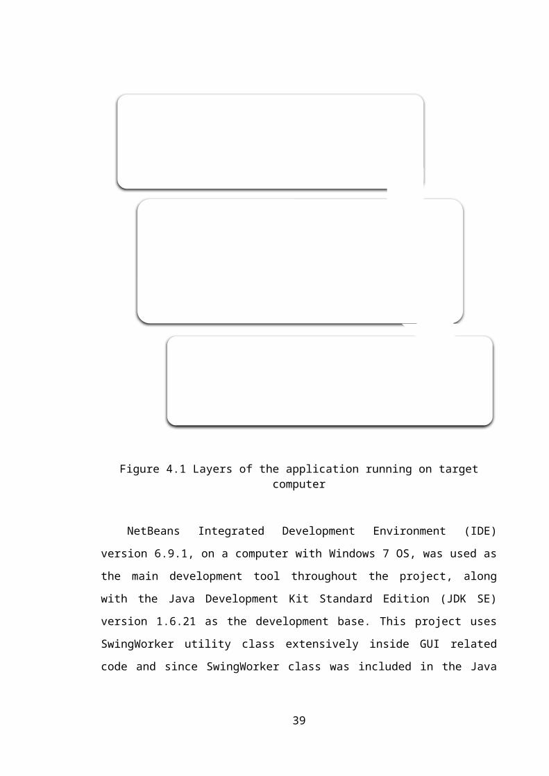
while the stickiness is set to two. The effect of decreasing keyboard wait to click time
parameter was mostly described as “allows typing quickly” and “easy to make typos”.
Increasing W, test subjects complained that it took so long to type a key and they had a
hard time waiting on the same key for a long time.
For the overall keyboard experience, test subjects complained about the time
required to type meaningful sentences and the jitters in key navigation (which were still
present even while using the stickiness setting). The learning curve for the system was
found to be steeper than expected as the test subjects were able to use them system after
15 minutes of tutorial but, it took them nearly 30 minutes to use the system with full
potential. After reminding the subjects that, this system was designed for disabled
people, subjects decided on their final rating for the keyboard control as “satisfactory
enough”.
5.2 Mouse Control Test
Mouse control tests were conducted in the following manner: eight identical circle
shapes were placed randomly in a canvas with size 800 pixels width to 600 pixels height,
using Microsoft Paint. Then the paint bucket tool was selected and test subjects were
requested to click on each circle shape to paint that circle shape. Mouse movement speed
parameter has heavy effect on mouse control and therefore, tests were repeated for three
different mouse speeds (10, 14, and 18). Also, each test was done three times for each
test subject. The time it took for each test subject to paint all circles was measured and
number of unintended clicks was counted. Results of this test are presented in Table 5.4.
For the overall mouse control experience, test subjects described the click mode as
“too complicated to use” and they had difficulty when making click movements most of
the time. They also had difficulty moving the mouse cursor and commented that “the
system acts as if it is frozen or stuck” when tried to move the mouse when in click mode.
After 15 minutes of getting used to the system, subjects were able to better control the
mouse movements. Because of the difficulties introduced by click mode, the advantage
43
of the speed adaptable relative mapping algorithm was mostly not seen. Despite that,
subjects commented that the relative mapping provides a natural way of moving the
cursor. Also, subjects favored slow mouse speed parameters as it provided more precise
control.
Speed Parameter 10 pixels 14 pixels 18 pixels
Time (s)
UnintendedClick Count
Time (s)
UnintendedClick Count
Time (s)
UnintendedClick Count
Subject A Test 1 125 2 122 3 166 2
Test 2 132 3 118 1 144 2Test 3 128 1 125 1 161 3Average 128 2 121 2 157 2
Subject B Test 1 183 5 191 2 186 2
Test 2 164 3 180 1 217 5Test 3 166 2 203 3 194 3Average 171 3 191 2 199 3
Average 149 2 156 2 178 2
Table 5.4 Mouse control test results
As done in the keyboard control tests, test subjects were, again, requested to do the
same test using traditional keyboard mouse for reference, results of this test are presented
in the Table 5.5.
Normal Mouse
Time (s) Unintended Click Count
Subject A Test 1 7 0
Test 2 7 0Test 3 8 0Average 7 0
Subject B Test 1 13 1
Test 2 10 0Test 3 11 0Average 11 0
Average 9 0
Table 5.5 Mouse control test results for normal mouse
44
6. CONCLUSION AND FUTURE WORK
The final product of this project did not fully meet the expected usability and
precision levels for controlling a computer using only head movements but, it provided a
strong base for future work by the evaluation of it. The proposed mouse click mode
method was not favored by the test users but, the mentioned complaints are mostly
solvable by small updates to the click mode implementation. Although test users had
mixed comments about keyboard control mode, when compared to similar solutions, it
provided a competitive typing performance. The acceleration sensor, included in TI
Chronos, was sensitive enough for basic controls but, it was noted that using two
accelerometers would benefit the system accuracy as well as the jitters with the keyboard
navigation.
As future development, more sophisticated head movement mappings for
simulating mouse click events can be designed and implemented, which would benefit
the system hugely. And adding a more creative keyboard control layout would also
increase the overall system usability. Also, more flexible analysis algorithms and
interfaces can be used provide an alternative computer control interface not only to
disabled people but, to non-disabled people too. To present the alternative computer
controlling idea as a commercial product, a special cap or hat can be designed with
multiple built in accelerometers located perfectly, which would make the system more
appealing to all user types and provide better input signal to the system at the same time.
45
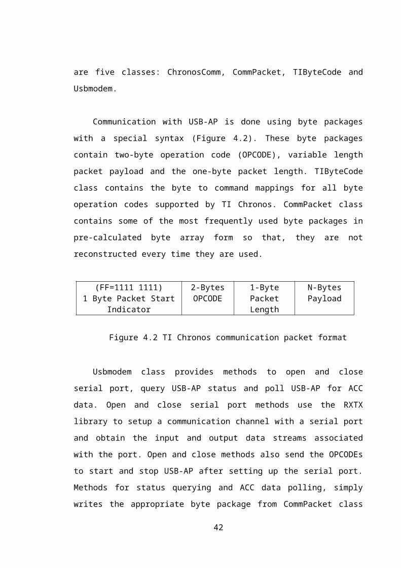
REFERENCES
1. Young wook Kim, Jung hyun Cho. “A novel development of head-set type computer
mouse using gyro sensors for the handicapped”, Microtechnologies in Medicine & Biology
2nd Annual International IEEE-EMB Special Topic Conference on pp.356-360, 2002.
<http://ieeexplore.ieee.org/stamp/stamp.jsp?tp=&arnumber=1002346&isnumber=21629>
DOI: 10.1109/MMB.2002.1002346
2. Yu-Luen Chen. “Application of tilt sensors in human-computer mouse interface for
people with disabilities”, Neural Systems and Rehabilitation Engineering, IEEE
Transactions on vol.9, no.3, pp.289-294, Sept. 2001.
<http://ieeexplore.ieee.org/stamp/stamp.jsp?tp=&arnumber=948457&isnumber=20532>
DOI: 10.1109/7333.948457
3. Huang, Sara Xiangrong, Jesse McMullen, and Wai Shing Wong. “Cornell University
ECE476 Final Project”. Courses.cit.cornell.edu. Cornell University. Web. 2008.
<http://instruct1.cit.cornell.edu/courses/ee476/FinalProjects/s2008/xh33_jdm55_ww239/
xh33_jdm55_ww239/index.html>
4. "Tilt measurement using a low-g 3-axis accelerometer" AN3182 Application note.
Version Doc ID 17289 Rev 1. STMicroelectronics, 1 Apr. 2011. Web. 15 May 2011.
<www.st.com/stonline/products/literature/an/17289.pdf>
5. "Technical:Accelerometer Fundamentals - Openmoko" Main Page - Openmoko.
Version 53994. Openmoko, Inc., 15 Sept. 2008. Web. 15 May 2011.
<http://wiki.openmoko.org/index.php?
title=Technical:Accelerometer_Fundamentals&oldid=53994>
46
6. Mu-Chun Shu, Yang-Han Lee, Cheng-Hui Wu, Shi-Yong Su, Yu-Xiang Zhao. “Two
Low-Cost Human Computer Interfaces for People with Severe Disabilities”, Biomedical
Engineering – Applications, Basis & Communications, on vol.16, no.6, pp.344-349, Dec.
2004.
7.Toole, Jack, Aaron King, and Libo He. "Chronos Flying Mouse" Texas Instruments
Embedded Processors Wiki. Version 03:33, 8 August 2010. Texas Instruments, 22 July
2010. Web. 15 May 2011.
<http://processors.wiki.ti.com/index.php/Chronos_Flying_Mouse>
8. Allen, Eric, and Michael O'Keefe. "CAGE - Chronos Advanced Gesture Engine" CAGE
- Chronos Advanced Gesture Engine. Rensselaer Center for Open Source Software, 27 Jan.
2010. Web. 14 May 2011. <http://chronosgestures.posterous.com>
9. Gips, James, and Margrit Betke. "Camera Mouse" Camera Mouse. Boston College and
University, n.d. Web. 18 May 2011. <http://www.cameramouse.org/>
10. "HeadMouse." Origin Instruments Corporation. N.p., n.d. Web. 15 May 2011.
<http://www.orin.com/access/headmouse/>
11. Eun Yi Kim, Sin Kuk Kang, Keechul Jung, Hang Joon Kim. "Eye mouse: mouse
implementation using eye tracking" Consumer Electronics, 2005. ICCE. 2005 Digest of
Technical Papers. International Conference on , vol., no., pp. 207- 208, 8-12 Jan. 2005
<http://ieeexplore.ieee.org/stamp/stamp.jsp?tp=&arnumber=1429790&isnumber=30841>
DOI: 10.1109/ICCE.2005.1429790
47

12. Mu-Chun Shu, Shi-Yong Su, Gwo-Dong Chen. “A Low-Cost Vision-Based Human-
Computer Interface for People with Severe Disabilities”, Biomedical Engineering –
Applications, Basis & Communications, on vol.17, no.6, pp.284-292, Dec. 2005.
13. Norris, G., Wilson, E.. "The Eye Mouse, an eye communication device"
Bioengineering Conference, 1997., Proceedings of the IEEE 1997 23rd Northeast , vol.,
no., pp.66-67, 21-22 May 1997 <http://ieeexplore.ieee.org/stamp/stamp.jsp?
tp=&arnumber=594960&isnumber=13027>
DOI: 10.1109/NEBC.1997.594960
14. Zhao Lv, Xiaopei Wu, Mi Li, Chao Zhang. "Implementation of the EOG-Based
Human Computer Interface System" Bioinformatics and Biomedical Engineering, 2008.
ICBBE 2008. The 2nd International Conference on , vol., no., pp.2188-2191, 16-18 May
2008 <http://ieeexplore.ieee.org/stamp/stamp.jsp?tp=&arnumber=4535757&isnumber=4534880>
DOI: 10.1109/ICBBE.2008.877
15. "Temperature, Wireless, USB Data Logger | Watch Development Tool | TI.com" Focus
Home Page. Texas Instruments. Web. 14 May 2011.
<http://focus.ti.com/docs/toolsw/folders/print/ez430-chronos.html>
16. Trent Jarvi, and Keane Jarvi. "Rxtx" Welcome to the RXTX wiki. Version revision
6634. Keane Jarvi, 21 Mar. 2011. Web. 15 May 2011.
<http://rxtx.qbang.org/wiki/index.php/Main_Page>
48