Embed Size (px)
Citation preview

Controlling the Indoor Winter Air – Furnaces & Boilers
The fundamental purpose of an architectural residential heating system is to maintain comfortable indoor air temperatures during cold weather. Most heating systems accomplish this by converting various kinds of stored energy to heat energy and then delivering it to the living spaces. Systems that burn organic fuels are called combustion appliances. Systems that convert electric energy are called electric appliances. Appliances that distribute heat by moving air through the home are called furnaces. And Appliances that distribute heat by moving warm water are called boilers.
The Standard requires that we inspect the installed heating equipment and the
associated vent systems, flues, and chimneys; and that we describe the energy source and the heating system by its distinguishing characteristics. So let’s limit our discussion to installed systems – not portable or temporary space heaters. We’ll talk about vents, flues, and chimneys in conjunction with our discussion of combustion appliances. But for now, let’s explore some fundamentals of energy.
Energy Energy takes many forms and can be stored and transported in many ways. Water stored above a dam, a battery sitting on a shelf, gasoline in an automobile gas tank, and an oil well in the Middle East are all examples of different means of storing energy.
When we allow water to fall over a turbine in a hydroelectric power plant, we convert energy stored as gravitational potential energy to mechanical energy. This mechanical energy then turns a generator and is in turn converted to electric energy. We then transfer electric energy to our homes and businesses through the power grid. Eventually, we convert this electric energy to heat energy by pushing an electric current through a resistor. We transfer the heat from this resistor, the heating element, to the air. And finally, we distribute heat energy to the living spaces through supply ducts.
Similarly, we pump oil out of a well and ship this fuel to North America where
we distribute it to homes and offices, store it on site, and eventually pump it into a combustion chamber where we ignite it. Through a combustion process in the heating appliance then, we convert stored chemical energy to heat energy. At this point we transfer the heat energy to some distribution medium in order to distribute the heat to the living spaces. If this distribution medium is water, we call the appliance a boiler. If the distribution medium is air, we call it a furnace.
In our first example, where we converted potential energy to electric energy at a
hydroelectric plant, we had no combustion fumes to deal with. If however, we had used an organic fuel, natural gas for instance, as our energy source, handling of combustion fumes would have been an issue. That problem though, would have been dealt with at the power plant. In our second example, where we burned the fuel in the combustion
1

chamber of the appliance on site, removal of combustion fumes would have been a significant issue in the home.
There are two descriptive terms commonly used in the industry that are easily
confused – draft and gravity. For our purposes, the term draft does not refer to air movements within the living spaces – a draft from an open window, for instance. Rather, we use the term draft in our discussions of combustion fumes. We remove the byproduct of combustion, the fumes, from the house by ensuring a draft up the flue. This is accomplished in a conventional natural draft appliance by natural convection – warm air rises. The term gravity also refers to a process of natural convection, but this time we’re referring to heat distribution. House air, having been warmed in a furnace will rise naturally through a system of ducts distributing heat to the living spaces. And the cooled air in the rooms will fall through a return duct, drawn by gravity, back to the appliance to be heated.
Now that’s an awful lot to put into a few short opening paragraphs, so let’s slow
down and try applying some of these concepts to the real world.
Gas-fired, Natural Draft, Gravity Furnace (Octopus) We said that a heating appliance that uses air as the distribution medium is called
a furnace. We recognize this appliance as a furnace by the ducts. We see one large duct that conducts cooler air from the home to the system. The air is warmed as it passes over
the outside of the combustion chamber. Air falls in the return because it is cooler and therefore heavier than the warm air that is rising through the supply ducts. Because the distribution medium is air and distribution is accomplished by simply allowing the warm air to rise naturally through the supply ducts, we call this appliance a gravity furnace.
We also recognize this furnace
to be gas-fired. We see a gas supply line, a gas pressure regulator, a gas control valve, a gas burner and we see
a light blue natural gas flame in the combustion chamber. We bring natural gas to this system through a pipe that is called a gas line. Gas is controlled at the pressure regulator and the control valve. Gas is mixed with air and ignited at the burner. The flame is contained in the combustion chamber, and combustion fumes are allowed to draft up the flue to the outdoors by natural convection. Because the combustion fumes rise naturally up the flue without the aid of a fan, we call this a natural draft system.
2
Because this system does not employ a blower fan to move air through the supply ducts, the air in the ducts is at atmospheric pressure. There is therefore, no force pushing the air through the ducts. It simply rises from the furnace, through the ducts and into the rooms. Because a gravity system has little energy available to move air through long or complex ducting systems with numerous branches, a gravity system requires a single dedicated duct for each room. Hence this systems nickname, the octopus. Heat Exchanger The combustion chamber of a fossil-fuel burning furnace is surrounded by a heat exchanger. In a conventional gas-fired furnace the heat exchanger is a sheet metal container that is open at both the top and the bottom. The burner sits in the heat exchanger and the flame is contained within this chamber. Air from the house is allowed to enter the heat exchanger from the bottom ensuring an adequate oxygen supply. Gas pressure and flow are carefully regulated to ensure a proper fuel/air mixture. Combustion fumes are allowed to escape through the top opening, and the heat is allowed to pass through the sheet metal wall of the heat exchanger where it is transferred to the house air. Air is directed from the house through the return duct and across the outside of the heat exchanger. As the air comes into contact with the wall of the heat exchanger, it absorbs heat energy before it is directed through the supply ducts to the living spaces. The primary purpose of the heat exchanger is to move heat from the combustion products to the house air without mixing the two. We want the air to come into close proximity of the flame in order to maximize the heat transfer, but we don’t want the combustion fumes to contaminate the house air. So the integrity of the heat exchanger is crucial. Because the heat exchanger is exposed to extreme temperature variations and humidity, the sheet metal is subject to metal fatigue and rust. Either and sometimes both of these deterioration factors limit the life of the heat exchanger. The problem with inspecting the heat exchanger is limited visibility. Convection
An engineer would tell us that heat is transferred in three ways – conduction,
convection, and radiation. Convection is defined as a method of heat transfer that involves moving heated matter. In the case of the distribution system of the gravity furnace that we just discussed, the heated matter is the house air. It absorbs heat energy as it passes over the outside of the heat exchanger. The warm air, being less dense and therefore lighter than the surrounding cooler air in the home, rises naturally through the supply ducts. In the individual rooms, this warm air is diluted by the air in the house. The cooler air in the house, being denser and therefore heavier than the supply air falls through the return duct back to the furnace where it repeats the cycle. We call this process natural convection. In the case of the forced air furnace, where the air is moved
3

by a blower fan, the force of the pressure induced by the fan overrides the natural buoyancy of the warm air. In this system, heat is transferred by forced convection.
In order to work properly, a gravity system must be located below the living
spaces. A forced air system can be located at any elevation within the house. Conduction Conductive heat transfer involves energy passing through matter. It always manifests as the migration of energy from the area of higher temperature to the area of lower temperature. In the case, once again, of our gas-fired furnace, chemical energy is being converted to heat energy inside the heat exchanger. Heat is being drawn away from the outside of the heat exchanger by the convective process of air moving over the outside of the heat exchanger. It is therefore, warmer inside the heat exchanger than it is outside. We call this difference in temperature Delta-T. The rate of conductive heat transfer is a function of both Delta-T and the ability of the material to conduct heat. The heat exchanger is made of a metal that is a very good conductor and is very thin. It is warmer inside the heat exchanger than it is outside, so we can expect that heat will conduct readily through the wall of the heat exchanger. Radiation Radiant heat travels in waves through space, but requires line-of-sight. Any material body with a temperature above absolute zero radiates heat by virtue of the fact that it has temperature. Radiative exchange of energy between two bodies depends on their relative temperatures, their relative reflectivities, and their relative surface areas. It’s quite complex, but for our purposes, it is fair to say that the net energy transfer is from higher temperature to lower temperature. The greater the Delta-T between the heat source and the destination, the greater the rate of heat transfer.
Taking another look at our gas-fired gravity furnace, we have the energy that is converted by the combustion process radiating from the flame to the inside surface of the heat exchanger where it is readily absorbed. Heat transfers through the wall of the heat exchanger by conduction. There is a significant Delta-T between the outside surface of the heat exchanger and the air passing over it, so heat is transferred by conduction to the air that comes into contact with the heat exchanger. Cold air, falling through the return duct, displaces the warm air driving the convective loop that distributes heat through the house. Control Valve The gas control valve is a simple device that opens and closes a port through which gas is directed to the burner.
4

Pilot In our conventional systems, ignition is accomplished by the pilot. The pilot is a device that maintains a small gas flame year round typically at the lower opening of the heat exchanger. This flame exists, ready to ignite the gas upon its release by the control valve. For safety reasons, a heat sensor, called a thermocouple, sits in the pilot flame to ensure that the pilot is lit. If the pilot goes out, the thermocouple aoverrides the control valve and will not allow it to open.
utomatically
Thermostat The standard tells us that we are to perform a visual inspection using the normal operating controls. The normal operating control of a heating appliance is usually a thermostat. A basic thermostat is a simple device that compares room temperature to a
user determined set-point. The occupant of the home sets the set-point at some desirable point on a temperature scale. When the room temperature falls below this set-point, the gas control valve opens, releasing gas through the burner into the heat exchanger where it is ignited by the pilot. As the system runs, room temperature rises until it exceeds the set-point. The thermostat then sends an electronic signal to the control valve. The valve closes. And the system shuts down.
So in summary; we have energy stored in the form of natural gas fuel being conducted to the furnace through a gas-line. Gas pressure is controlled by the pressure regulator. The user interface is the thermostat. The occupant sets the thermostat at a desirable set-point. With the system at rest, room temperature falls to a point below the set-point. The thermostat sends an electronic message to the control valve. The thermocouple proves the pilot. The control valve opens, allowing gas to flow to the burner. Gas is mixed with air to provide an appropriate fuel/air mixture. This mixture is ignited by the pilot. Potential energy is converted to heat energy through a combustion process. Combustion fumes draft up the flue by natural convection and heat radiates from the flame to the inside wall of the heat exchanger. Heat energy, driven by Delta-T, conducts through the wall of the heat exchanger where it meets the distribution air. Air molecules that come into contact with the outside surface of the heat exchanger absorb heat by conduction. This warmed air, being less dense than the air in the living space, rises by natural convection through the supply ducts until it is released into the individual rooms. Being warmer than the air in the room it rises to the ceiling, but as it is diluted by the air in the room, cools and falls evenly through the room creating a comfortable living area. Continuing to fall, the air in the house finds its way to the return duct where, being
5

denser and therefore heavier than other air in the loop, it falls back to the furnace to be heated. With the system running now and delivering warm air to the house, room temperature rises until it exceeds the thermostat set-point. The thermostat then tells the control valve to close itself. Gas ceases to flow. Combustion is halted. Air begins to stagnate. Room temperature drops below the set-point and the cycle repeats. This is as simple as a gas-fired furnace gets – natural draft, gravity distribution. Forced-Air The defining difference between a gravity furnace and a forced-air furnace is the presence (or absence) of the blower fan. A gravity furnace distributes heat by allowing warm air to flow through a series of supply and return ducts, influenced by natural convection. A forced-air furnace employs a blower fan to move the air through a series
of supply and return ducts. The blower fan is typically located in the blower housing upstream of the heat exchanger. It draws air from the house, through the return duct, and then pushes it across the heat exchanger and through the supply ducts to the living spaces. In this typical configuration, the return duct is under negative pressure and the supply ducts are under positive pressure. Air will be drawn in through openings in the return and blown out through openings in the supply. By
design, the openings in the return through which air is to be drawn are the return grills. The openings in the supply through which air is to be exhausted are the supply registers or diffusers. Filters Forced-air systems move a lot of air. That air is full of contaminants – dust, hair, pet and human dander, and material fibers from carpet, furniture and clothing, etc. Some of these materials are organic and therefore potentially allergenic. Some of them are abrasive and therefore potentially detrimental to the fan bearings. So a filter is installed upstream of the working components designed to extract this particulate in order to protect both the occupants and the system. We find four basic types of filters – disposable, washable, electronic, and electrostatic.
• Disposable filters are just that –disposable. Typically, a fiberglass mesh in a cardboard frame that fits into an opening in the return duct.
• Plastic or metal washable filter are a similar option and typically fit into the same filter opening.
6
• In an electronic filter contaminated air first passes over a high-voltage electrode in the form of a grid of sharp points. When the particles touch this electrode, they pick up the charge on the electrode and then are immediately repelled back into the air stream (like charges repel). Just downstream there is another grid with the opposite charge to the first grid. This grid attracts the particles (like charges attract) and collects them in massive amounts. The particulate then falls into a collection hopper.
• In a modern electrostatic filter, we don’t need an outside source of electricity because the charge separation takes place as a result of friction between the dust particles and plastic fibers in the filter medium. As the air stream carries dust through the filter medium, the dust particles rub against the plastic fibers of the medium and become charged in a exactly the same way as rubbing a balloon on your sweater (the sweater is the dust; the balloon is the filter). The dust and the filter medium are now oppositely charged and will stick to each other.
All of these filters require routine maintenance. Filters that are not cleaned or
replaced become clogged and two things happen. First, air flow is restricted, causing the system to be inefficient and eventually to overheat. Second, unfiltered air is drawn through around the perimeter of the filter and through other unintended openings and gaps in the return plenum. Unfiltered air bypasses the filter defeating its purpose. Air flow is restricted, driving up the cost of heating and causing the system to malfunction.
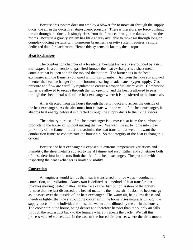
Gas Shut-off valve Every fossil fuel burning appliance must have a shut-off valve. This valve is
typically installed in the gas-line within reach of the equipment. Most gas valves are designed so that when the handle is parallel to the pipe, the valve is on and when the handle is perpendicular to the pipe it is off. The fuel shut-off valve is intended for use by service personnel and is not considered to be a normal operating control.
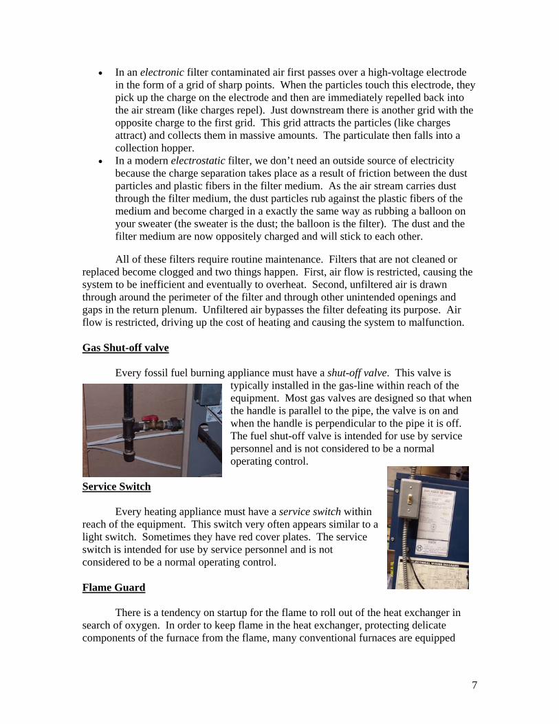
Service Switch Every heating appliance must have a service switch within reach of the equipment. This switch very often appears similar to alight switch. Sometimes they have red cover plates. The service switch is intended for use by service personnel and is not considered to be a normal operating control.
Flame Guard There is a tendency on startup for the flame to roll out of the heat exchanger in search of oxygen. In order to keep flame in the heat exchanger, protecting delicate components of the furnace from the flame, many conventional furnaces are equipped
7
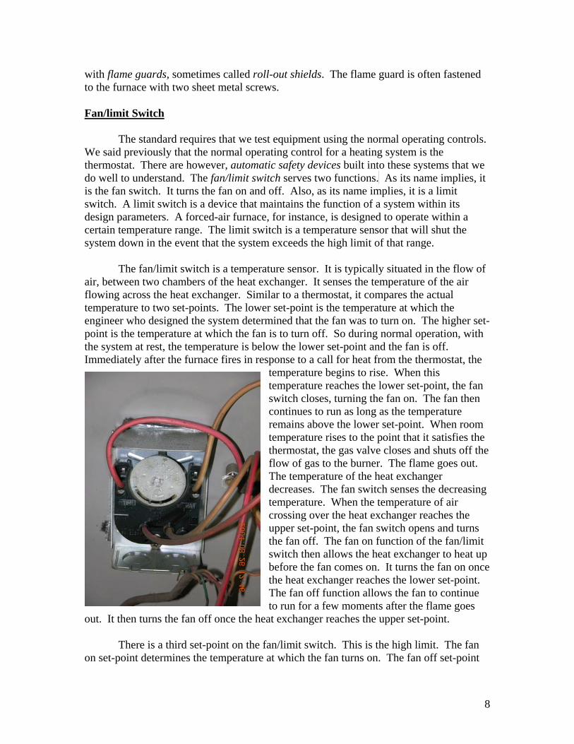
with flame guards, sometimes called roll-out shields. The flame guard is often fastened to the furnace with two sheet metal screws. Fan/limit Switch The standard requires that we test equipment using the normal operating controls. We said previously that the normal operating control for a heating system is the thermostat. There are however, automatic safety devices built into these systems that we do well to understand. The fan/limit switch serves two functions. As its name implies, it is the fan switch. It turns the fan on and off. Also, as its name implies, it is a limit switch. A limit switch is a device that maintains the function of a system within its design parameters. A forced-air furnace, for instance, is designed to operate within a certain temperature range. The limit switch is a temperature sensor that will shut the system down in the event that the system exceeds the high limit of that range. The fan/limit switch is a temperature sensor. It is typically situated in the flow of air, between two chambers of the heat exchanger. It senses the temperature of the air flowing across the heat exchanger. Similar to a thermostat, it compares the actual temperature to two set-points. The lower set-point is the temperature at which the engineer who designed the system determined that the fan was to turn on. The higher set-point is the temperature at which the fan is to turn off. So during normal operation, with the system at rest, the temperature is below the lower set-point and the fan is off. Immediately after the furnace fires in response to a call for heat from the thermostat, the
temperature begins to rise. When this temperature reaches the lower set-point, the fan switch closes, turning the fan on. The fan then continues to run as long as the temperature remains above the lower set-point. When room temperature rises to the point that it satisfies the thermostat, the gas valve closes and shuts off the flow of gas to the burner. The flame goes out. The temperature of the heat exchanger decreases. The fan switch senses the decreasing temperature. When the temperature of air crossing over the heat exchanger reaches the upper set-point, the fan switch opens and turns the fan off. The fan on function of the fan/limit switch then allows the heat exchanger to heat up before the fan comes on. It turns the fan on othe heat exchanger reaches the lower set-point.The fan off function allows the fan to continueto run for a few moments after the flame goe
out. It then turns the fan off once the heat exchanger reaches the upper set-point.
nce
s
There is a third set-point on the fan/limit switch. This is the high limit. The fan on set-point determines the temperature at which the fan turns on. The fan off set-point
8

d ines the temperature at which the fan turns off. The high limit set-point is the temperature above which the system is not allowed to operate. In the event that some malfunction occurs, allowing the temperature of the heat exchanger to exceed that at which it was designed to operate, the fan/limit switch will reach the high limit. At this point, the limit function of the fan/limit switch sends an electronic signal to the gas vacausing it to close, shutting off the flow of gas to the burner.
eterm
lve
Units of Energy We described earlier, many different kinds of energy. We saw that energy takes
any different forms. We talked about its being converted from form to form, moved rom p
. A British thermal unit is a nit of energy specifically formulated to quantify heat energy. It is by definition the
amoune
nergy
capacities are typically reported in BTU/h. However, there are any other equivalent units that are used from time to time and place to place. The Watt
is anoth
mf lace to place, and passed from industry to industry often crossing international borders in the process. In all this activity, there is need for standardized methods of computing quantities and rates of transfer and/or conversion.
BTU is an acronym that stands for British thermal unitu
t of heat energy required to raise the temperature of one pound of water one degree Fahrenheit. Because scientists have quantified the amount of energy stored in a volumof natural gas, we can easily measure gas in BTUs. A therm is a quantity of gas that contains 100,000 BTUs of energy. So a gas-fired heating appliance that converts chemical energy to heat energy at a rate of one therm per hour is often referred to as having a capacity of 100,000 BTU/h. BTU is a unit of energy. Btu/h is a unit of econversion. Because we transfer energy at the same rate at which we consume it, it isalso a parallel unit of energy transfer. To simplify things, let’s think of BTU/h as a rate of energy consumption.
Heating appliancem
er unit of energy consumption. We tend to think of the Watt as a unit of electric energy consumption, but it really refers to any kind of energy. A Watt is a unit of energy consumption equal to 3.413 BTU/h. Efficiency
We say that a system that consumes gas at a rate 100,000 Btu per hour has an put capacity of 100,000 Btu/h. That system however, is certain to have some built-in
inefficie
ace is
ple of the 100,000 Btu/h furnace, the input capacity in 100,000 Btu/h and the output capacity is 80,000
inency. Most conventional natural draft gas-fired furnaces lose about twenty
percent of the energy that they consume up the flue with the combustion fumes. They ardesigned that way. 20% of 100,000 Btu is 20,000 Btu. So our 100,000 BTU/h furnlosing heat up the flue at a rate of 20,000 Btu per hour. That leaves 80,000 Btu per hour left to heat the house. We call this 80,000 Btu/h the output capacity.
Efficiency is defined as the ratio of output to input. In our exam
9
Btu/h.
d
80,000 divided by 100,000 equals 0.80 or 80%. So we say that our system is 80% efficient.
Draft Hoo
are two openings into each chamber of the heat exchanger. The burners are tuated in the bottom where they receive gas from the control valve. The purpose of the
hanger. We call this opening the raft hood. Here we allow the combustion fumes, rising by natural convection, to leave
Theresiburners is to mix gas with oxygen. This combining of gas and air takes place in the heat exchanger. Gas is supplied by the gas line and metered by the control valve. Air enters the heat exchanger through the bottom port. The air source is the volume of air in the house. We call this air combustion air or primary air. The second opening is at the top of the heat excdthe heat exchanger on their way to the flue. However, we introduce air at this point as well to ensure a proper draft up the flue. We call this air dilution air or secondary air. All of this air, both primary and secondary, we call makeup air. Vent Connector The conduit for carrying combustion fumes from the appliance to the flue is alled a vent connector. It is typically made of sheet metal and must be securely
the cfastened. Because these systems depend on natural convection to channel fumes fromfurnace, the vent connector must be pitched up toward the flue. Flue
Most conventional furnaces vent combustion fumes out of the house through the rra cotta clay flue lining of a masonry chimney. Flue gas temperature must stay warm
long eno
2. The height of the chimney
Flue gases are highly acidic. These acids tend to erode flue liners over the years.
ome older chimneys were built without flue liners. Flue liners are difficult to evaluate. Unlined
teough for the convective current to carry the fumes to the top of the flue. In order
for a flue to draft properly, it must be engineered appropriately. There are three factors tconsider:
1. The capacity rating of the appliance
3. The dimensions of the flue liner
S flues or significantly deteriorated flues are often apparent from the roof.
Makeup Air
entional gas-fired furnace operates with an air to gas ratio of pproximately thirty to one. For every one cubic foot of gas we need about fifteen cubic
feet of combustion air and fifteen cubic feet of dilution air.
A conva
10
As long as the appliance sits in the basement with access to the entireair in the basement, it is safe to assume that there is adequate makeup air. However, if the appliance is enclosed in a utility room, ventilation becom
volume of
es necessary. In order to nsure an adequate flow of free flowing air to a gas-fired appliance, we look for an e
opening into the utility room with a minimum opening of 100 square inches for every 100,000 BTU/h of furnace capacity. Louvers restrict the flow of air by approximately 30%. So a 10” x 10” louvered opening is equivalent to 70 square inches.
Back draft If we find evidence that a gas-fired appliance is spilling combustion fumes into the house rather than drafting them up the flue, we do well to ask ourselves, why? What
h the setup that is causing the system to malfunction? And what are the plications?
flue son, an animal, or any other factor is certain to cause combustion fumes to
ow out through the draft hood rather than up the flue.
e flue, an especially long vent connector may have been used to make the connection. If comb
e been known to draw combustion air down the flue and to exhaust fumes through the draft hood.
he product of the complete combustion of pure natural gas is heat, but the chemic
gen and expels CO2. Excessive CO2 concentrations in the air can interfere with this natural process. We can
he
s, but
is wrong witim First let’s consider the cause. The most obvious cause of a back draft is some kind of blockage in the flue. A bird nest or some other foreign material placed in the either by a perfl
Another likely cause might simply be a long horizontal run or an especially tall chimney or oversized flue. Remember that we’re counting on natural convection to causethe combustion fumes to draft up the flue. If our appliance is located some distance fromth
ustion fumes are allowed to cool before they exit the chimney, they are unlikely to successfully draft all the way to the outdoors. Trapped in the flue, these gases continue to cool and eventually fall back to the appliance.
A third possibility might be a lack of makeup air. Consider the furnace in the
utility room without adequate ventilation. Remember that the purpose of the secondary air is to ensure a draft up the flue. Appliances hav
This phenomenon of combustion fumes spilling back through the draft hood
rather than rising up the flue is often referred to as spillage. Tal reaction that takes place in the flame, yields the two byproducts, water (H2O)
and carbon dioxide (CO2). The human body breathes in oxy
though tolerate some level of CO2 in our breathing air, so CO2 contamination isn’t tsignificant issue. A constant flood of water vapor from the furnace all winter long does have the potential to raise humidity levels in parts of the house to undesirable levelthis really isn’t the significant issue either. A back drafting furnace is certainly not operating as designed. It may be inefficient and it might contribute to excessive carbon
11
dioxide and humidity levels in the home. But back drafting alone is not the big bugaboo. Not until we consider the fuel/air mixture. An appliance that has it’s burners out of adjustment or has inadequate access to makeup air is not going to have a proper fue
l to oxygen ratio and so is not going to burn roperly. A burn that is starved for oxygen is referred to as rich and a burn that is starved
e
il we
re. supply is forced out through any openings in the duct. By design, these
penings are supply registers and diffusers. The return is under negative pressure. Air is
cs and
is
properly, air is drawn in through the draft hood diluting the combustion
mes.
r or
ay,
pfor fuel is referred to as lean. We recognize a natural gas flame that is burning rich by thyellow tipping of the flame. A minor amount of yellow is difficult to avoid. But a flamethat exhibits any significant amount of yellow is not burning properly. We said that the byproducts of the complete combustion of pure natural gas were water and carbon dioxide. But with a flame that is burning rich we don’t get complete combustion. Now instead of carbon dioxide (CO2) we get carbon monoxide (CO) which is a poisonous gas.If the fumes are going up the flue; the problem is efficiency, not safety. It’s not untget the combination of malfunctions, the lean burn and the back draft, that we create the extreme unsafe condition – carbon monoxide in the house. In fact, the significant safety hazard still hasn’t been realized until we find a conduit for delivering this poisonous concoction to the living spaces. An opening into the return duct provides just such a conduit. Remember that in a forced air system, the supply duct is under positive pressuAir in theodrawn in through openings here. By design these openings are the return grills. Duct leakage in the supply can be inefficient, especially in unconditioned spaces like atticrawls spaces. Duct leakage in the return can be inefficient, but it can also be deadly when the opening is in a furnace closet with inadequate ventilation. An appliance that starved for makeup air is going to burn lean and it’s likely to back draft carbon monoxide into the room where it may be drawn up into the return duct and delivered to the livingspaces. Return grills are not allowed in furnace rooms. Filter covers are important safetyfeatures.
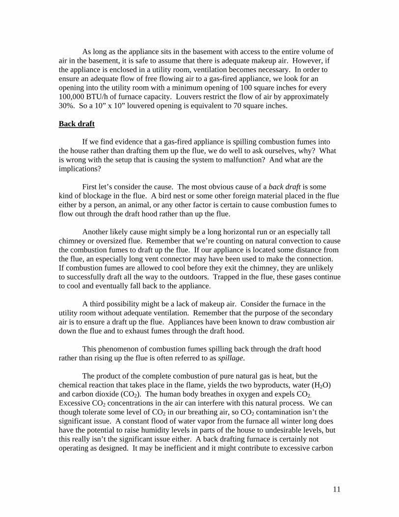
With the system drafting
fu The water in the fumes remains a vapor and is suspended in the flue gases. If however, the system begins to back draft, flowreverses, and water condenses. Water in the steel vent connectoat the draft hood can promote rust.Water condenses, evaporates awand leaves residual mineral deposits behind. Rust on the vent connector or in the draft hood is evidence of back draft.
12
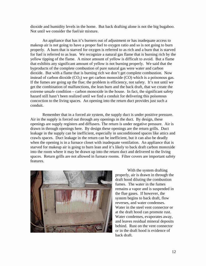
Cracked Heat Exchanger The heat exchanger is made of sheet metal. It is subject to constant variations of xtrem
ugh the
hanger
ressure
e e temperatures. The ensuing thermal expansion and contraction weakens the metal. This weakening eventually causes cracks to develop at weak points. There is
much made of the cracked heat exchanger with theories about combustion fumes passing throcrack into the flow of air causing carbon monoxide poisoning. However, because the heat excis downstream of the blower fan the passageways around the heat exchanger are under positive pwhile the air in the heat exchanger is atatmospheric pressure. We know that gases migrate naturally from high pressure to low pressure. So any going to be house air into the heat
exchanger rather than combustion fumes into the supply air. Nevertheless, the home inspector who overlooks the obvious cracked heat exchanger assumes substantial liability.
transfer of gas through a crack is almost certainly
Short-cycling According to the standard, we test a heating system by turning it on at the
ermo ce ot
d shuts
falls
it
Something as simple as a dirty filter could cause this to happen. The heat heat
t.
th stat, the normal operating control. For convenience, we might use the serviswitch. But these systems have built into them automatic safety devices that we are nrequired to test. The fan/limit switch is one such device. As we discussed above, the high limit function of the fan/limit switch is designed to keep the system from overheating. Before it gets to hot, the fan/limit switch reaches the high limit anthe system down. If this happens though, before the thermostat is satisfied, the thermostat continues to call for heat. As soon as the heat exchanger temperaturebelow the high limit, the system will turn right back on. If whatever is causing the system to overheat persists, temperatures will rise again to the high limit and the limfunction of the fan/limit switch will shut it down again. We call this condition a short-cycle. The thermostat calls for heat. The system overheats. The limit switch shuts it down. The thermostat continues to call for heat. Temperatures drop below the high limit. The system fires. Temperature reaches the high limit, and the cycle repeats. exchanger is warmed from within and cooled from without. If air flow across the exchanger is restricted, cooling is not accomplished, and the system is likely to overhea
13
A short-cycle may not be apparent to the occupant. If the system runs long-enough to keep the house comfortable, the condition could persist for years without anyone realizing it. The short-cycle though adds a significant strain to the components as it is constantly turning itself on and off. Short-cycling is likely to reduce the life expectancy of a system by nearly 50%. Inspection procedures Now that we have a general understanding of some of the basic components of a conventional gas-fired forced-air furnace, let’s talk just a little bit about how one might perform an inspection of one. I like to start my inspection with the furnace. There are a lot of basements in my area. The most common heating system around here, especially in newer homes, is the gas-fired forced-air furnace. And these furnaces are usually located in the basement. As a home inspector, I am a consultant. My typical client is a prospective home-buyer. The product that I provide my client (for a fee) is information. Information, in which a consumer of the information has no confidence, has no value. Therefore, if my client, the buyer, doesn’t believe that I know what I’m doing, the value of my service is diminished. Part of my job as a consultant to a prospective home buyer is to establish a relationship of trust and confidence. I have a very limited window of opportunity. First impressions are lasting impressions. So I dress professionally and I carry myself with an air of confidence (not bravado). At the very beginning, I introduce myself, my company, and my service. I get a signature on a pre-inspection agreement and I get right to work. At the earliest possible moment, before my customer gets distracted, I make the point of exhibiting that I know what I’m doing – that I understand the systems that I’m looking at; and that I know how to test them. What better opportunity than to take her directly to the basement where we can see the foundation, the floor structure, structural columns, basement dampness, the water service entrance, and the most complex component in the house – the furnace? Not only is the furnace the most complex, it is one of, if not the most expensive component with a routine replacement cycle. Its function is fundamental to both comfort and safety. This is a system that my customer is concerned about and one that I can readily and routinely use to display my expertise. It is also a significant area of liability. The home inspector, who polishes his furnace inspection, testing, and explanation techniques, has a significant competitive advantage in many parts of the country. So I routinely start my inspection with the furnace in the basement. In an initial pass through the house, I turn the service switch off, set the thermostat to the heat mode and crank the set-point up to 90 degrees. Now when I go back downstairs, I can control the system by the service switch.
14
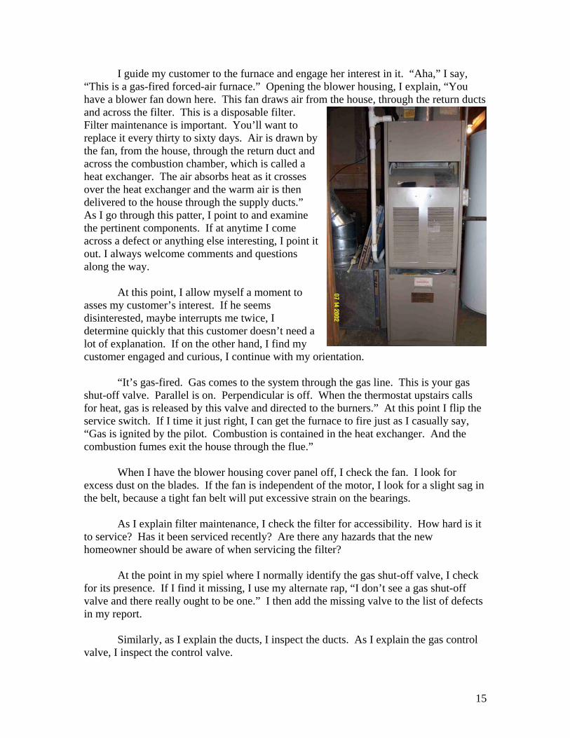
I guide my customer to the furnace and engage her interest in it. “Aha,” I say, “This is a gas-fired forced-air furnace.” Opening the blower housing, I explain, “You have a blower fan down here. This fan draws air from the house, through the return ducts and across the filter. This is a disposable filter. Filter maintenance is important. You’ll want to replace it every thirty to sixty days. Air is drawn bthe fan, from the house, through the return duct andacross the combustion chamber, which is called a heat exchanger. The air absorbs heat as it crosses over the heat exchanger and the warm air is then delivered to the house through the supply ducts.” As I go through this patter, I point to and examine the pertinent components. If at anytime I come across a defect or anything else interesting, I point iout. I always welcome comments and questions along the way.
y
t
At this point, I allow myself a moment to asses my customer’s interest. If he seems disinterested, maybe interrupts me twice, I determine quickly that this customer doesn’t need a lot of explanation. If on the other hand, I find my customer engaged and curious, I continue with my orientation. “It’s gas-fired. Gas comes to the system through the gas line. This is your gas shut-off valve. Parallel is on. Perpendicular is off. When the thermostat upstairs calls for heat, gas is released by this valve and directed to the burners.” At this point I flip the service switch. If I time it just right, I can get the furnace to fire just as I casually say, “Gas is ignited by the pilot. Combustion is contained in the heat exchanger. And the combustion fumes exit the house through the flue.” When I have the blower housing cover panel off, I check the fan. I look for excess dust on the blades. If the fan is independent of the motor, I look for a slight sag in the belt, because a tight fan belt will put excessive strain on the bearings. As I explain filter maintenance, I check the filter for accessibility. How hard is it to service? Has it been serviced recently? Are there any hazards that the new homeowner should be aware of when servicing the filter? At the point in my spiel where I normally identify the gas shut-off valve, I check for its presence. If I find it missing, I use my alternate rap, “I don’t see a gas shut-off valve and there really ought to be one.” I then add the missing valve to the list of defects in my report. Similarly, as I explain the ducts, I inspect the ducts. As I explain the gas control valve, I inspect the control valve.
15
When I come to the heat exchanger, I take a real close look. I like to use a flashlight and a flame mirror. If the flame shield looks like it will come off easily, I remove it. If, on the other hand, it is going to be difficult to access; or if it has any electrical components attached to it, I do my best to look into the heat exchanger without removing it. Remember, the standard requires that we open readily openable access panels. By no stretch of my imagination does the flame shield meet the definition of readily openable. At the same time though, the inspector who risks overlooking the readily available heat exchanger takes on some appreciable level of liability. I recommend that you look closely at the heat exchanger. Check for any and all indicators of failure:
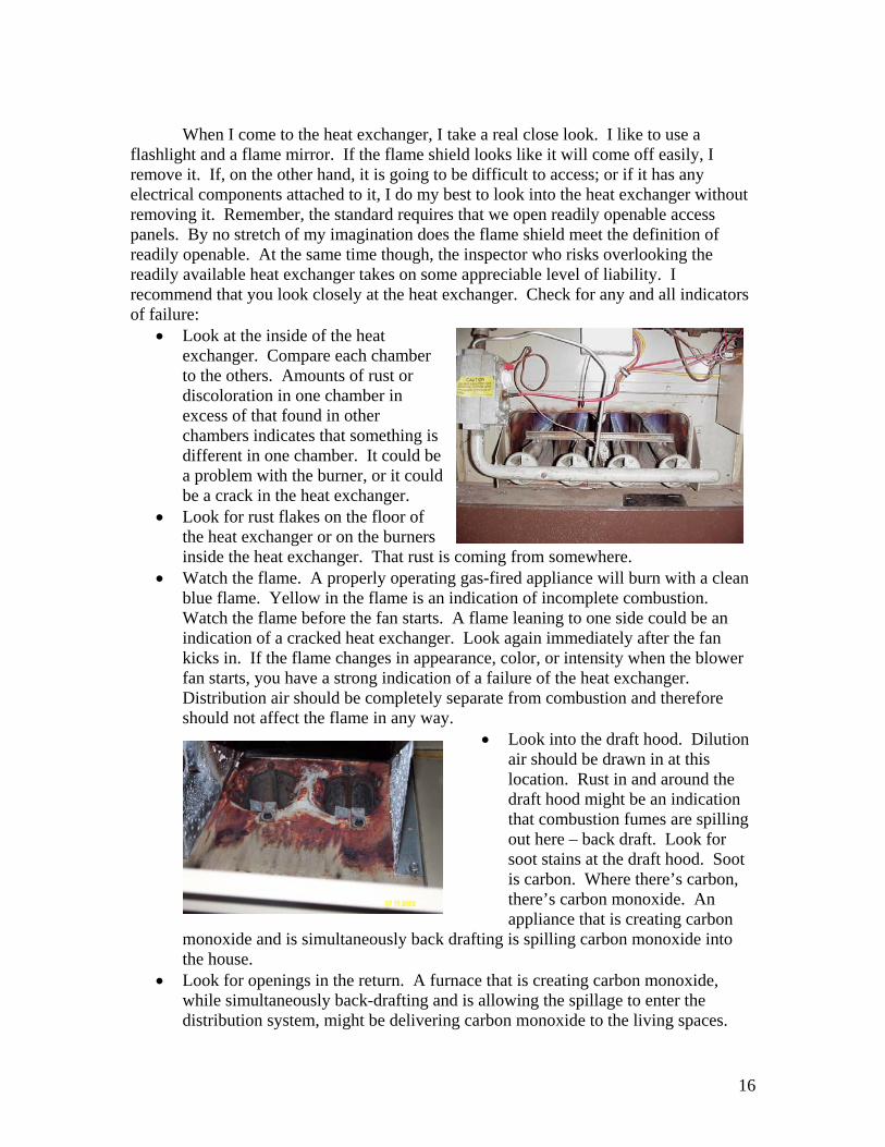
• Look at the inside of the heat exchanger. Compare each chamber to the others. Amounts of rust or discoloration in one chamber in excess of that found in other chambers indicates that something is different in one chamber. It could be a problem with the burner, or it cbe a crack in the heat exchanLook for rus
ould ger.
• t flakes on the floor of
• ly operating gas-fired appliance will burn with a clean
er
ore
• Look into the draft hood. Dilution
he
t
n monoxide and is simultaneously back drafting
• enings in the return. A furnace that is creating carbon monoxide, while simultaneously back-drafting and is allowing the spillage to enter the distribution system, might be delivering carbon monoxide to the living spaces.
the heat exchanger or on the burnersinside the heat exchanger. That rust is coming from somewhere. Watch the flame. A properblue flame. Yellow in the flame is an indication of incomplete combustion. Watch the flame before the fan starts. A flame leaning to one side could be anindication of a cracked heat exchanger. Look again immediately after the fan kicks in. If the flame changes in appearance, color, or intensity when the blowfan starts, you have a strong indication of a failure of the heat exchanger. Distribution air should be completely separate from combustion and therefshould not affect the flame in any way.
air should be drawn in at this location. Rust in and around tdraft hood might be an indication that combustion fumes are spillingout here – back draft. Look for soot stains at the draft hood. Soois carbon. Where there’s carbon, there’s carbon monoxide. An appliance that is creating carbois spilling carbon monoxide into
the house. Look for op
16
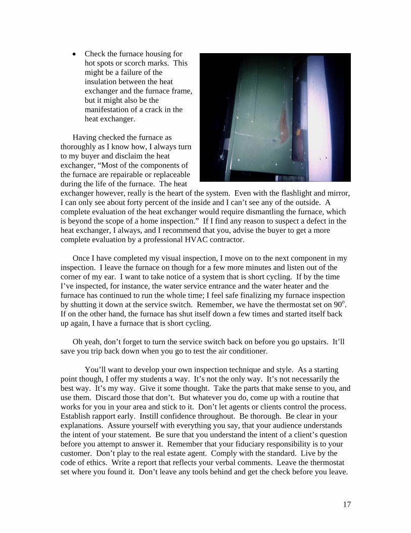
• Check the furnace housing for hot spots or scorch marks. This might be a failure of the insulation between the heat exchanger and the furnace framebut it might also be the manifestation of a crack in thheat exchanger.
ing checked the furnace as
,
e
Hav
thoroughly as I know how, I always turn my buyer and disclaim the heat
exc s of
heat tnside and I can’t see any of the outside. A
er would require dismantling the furnace, which
my inutes and listen out of the
corner of my ear. I want to take notice of a system that is short cycling. If by the time I’ve
n .
ck
air conditioner.
’s not necessarily the est way. It’s my way. Give it some thought. Take the parts that make sense to you, and
.
r
tohanger, “Most of the component
the furnace are repairable or replaceable during the life of the furnace. The exchanger however, really is the heart ofI can only see about forty percent of the icomplete evaluation of the heat exchangis beyond the scope of a home inspection.” If I find any reason to suspect a defect in the heat exchanger, I always, and I recommend that you, advise the buyer to get a more complete evaluation by a professional HVAC contractor.
Once I have completed my visual inspection, I move on to the next component in
inspection. I leave the furnace on though for a few more m
he system. Even with the flashlight and mirror,
inspected, for instance, the water service entrance and the water heater and the furnace has continued to run the whole time; I feel safe finalizing my furnace inspectioby shutting it down at the service switch. Remember, we have the thermostat set on 90o
If on the other hand, the furnace has shut itself down a few times and started itself baup again, I have a furnace that is short cycling.
Oh yeah, don’t forget to turn the service switch back on before you go upstairs. It’ll
save you trip back down when you go to test the
You’ll want to develop your own inspection technique and style. As a starting point though, I offer my students a way. It’s not the only way. Itbuse them. Discard those that don’t. But whatever you do, come up with a routine that works for you in your area and stick to it. Don’t let agents or clients control the processEstablish rapport early. Instill confidence throughout. Be thorough. Be clear in your explanations. Assure yourself with everything you say, that your audience understandsthe intent of your statement. Be sure that you understand the intent of a client’s question before you attempt to answer it. Remember that your fiduciary responsibility is to youcustomer. Don’t play to the real estate agent. Comply with the standard. Live by the code of ethics. Write a report that reflects your verbal comments. Leave the thermostat set where you found it. Don’t leave any tools behind and get the check before you leave.
17
Off-cycle Losses We’ve already discussed the basics of efficiency. Remember that we used the
,000 BTU/h furnace losing 20,000 BTU/h up the flue and delivering 0,000 BTU/h to the living space. We said that this furnace had an input capacity of
te
t it
fficiencies that we haven’t discussed yet. • These systems have a standing pilot. Here is more gas being consumed year
the flue. ing
•
air from the house and sending it up the flue as well. This is warm air
We cal Efficie vements
example of the 1008100,000 BTU/h, an output capacity of 80,000 BTU/h, and that it was 80% efficient. Nothough that these numbers all assume that the system is running. We say that it is consuming energy at a rate of 100,000 BTU per hour. This is different than saying thaconsumes 100,000 BTU each hour. Except under extreme winter conditions, a heat plant doesn’t run constantly for a whole hour. We talked about the inefficiency of heat being lost up the flue with the combustion fumes, but there are other ine
round. With the system at rest and the fan off, most of this heat goes upWhat little bit of heat it does deliver is counter productive in the summer coolmonths. How about the open flue? We’ve accounted for the heat that goes up the flue when the system is running, but what about the air that is lost up the flue between cycles?
• One of the most significant inefficiencies is the makeup air. Not only are we putting 20% of the heat that we’re generating up the flue, we’re also pulling makeup from the house that is certain to be replaced by cold air infiltrating the buildingenvelope. l these inefficiencies, off-cycle losses.
ncy Impro
Improvements tend to fall into two categories – safety and efficiency. A ement implemented in the first quarter of the 20th Century
as the blower fan. A forced air furnace is much more efficient than a gravity furnace. ents.
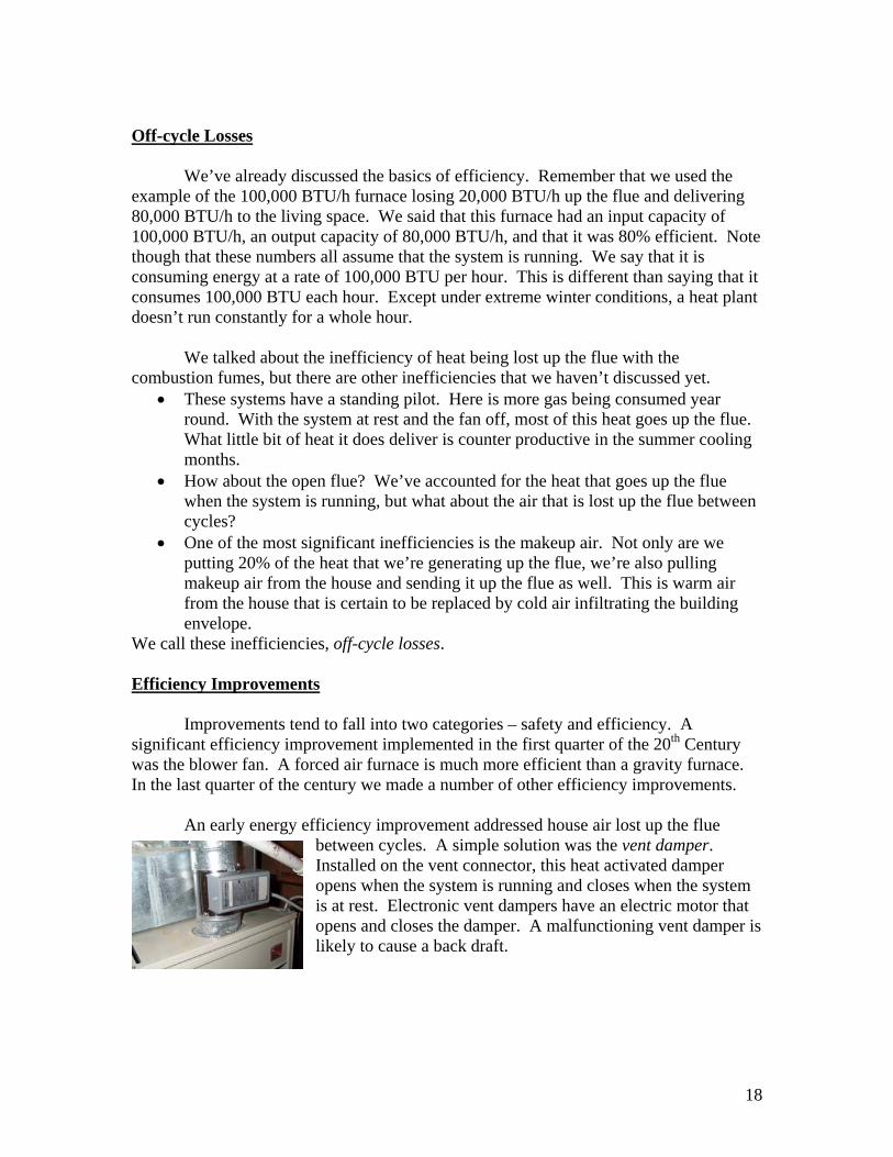
Installed on the vent connector, this heat activated damper em hat
significant efficiency improvwIn the last quarter of the century we made a number of other efficiency improvem An early energy efficiency improvement addressed house air lost up the flue
between cycles. A simple solution was the vent damper.
opens when the system is running and closes when the systis at rest. Electronic vent dampers have an electric motor topens and closes the damper. A malfunctioning vent damper is likely to cause a back draft.
18
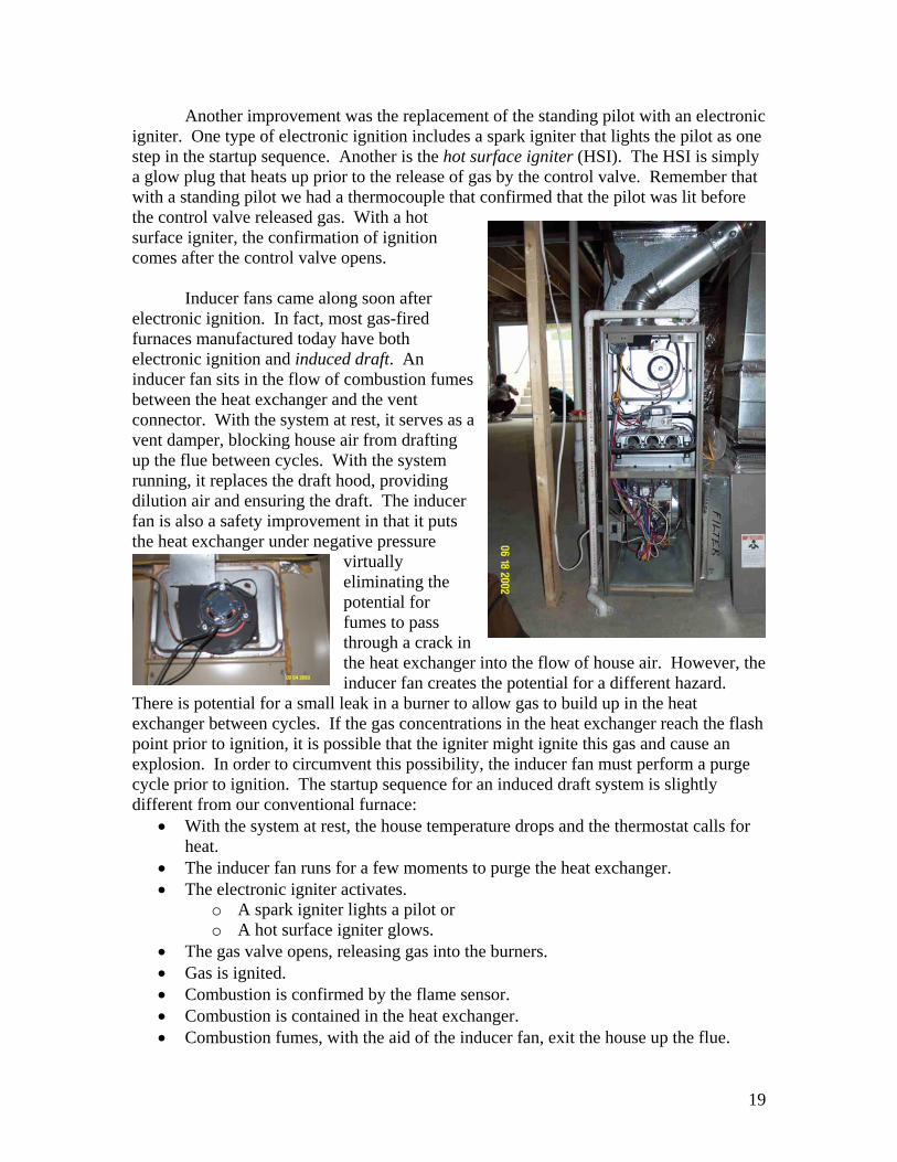
Another improvement was the replacement of the standing pilot with an electronic igniter. One type of electronic ignition includes a spark igniter that lights the pilot as one step in the startup sequence. Another is the hot surface igniter (HSI). The HSI is simply a glow plug that heats up prior to the release of gas by the control valve. Remember that with a standing pilot we had a thermocouple that confirmed that the pilot was lit before the control valve released gas. With a hot surface igniter, the confirmation of ignition comes after the control valve opens. Inducer fans came along soon after electronic ignition. In fact, most gas-fired furnaces manufactured today have both electronic ignition and induced draft. An inducer fan sits in the flow of combustion fumes between the heat exchanger and the vent connector. With the system at rest, it serves as avent damper, blocking house air from drafting up the flue between cycles. With the system running, it replaces the draft hood, providing dilution air and ensuring the draft. The inducer fan is also a safety improvement in that it puts the heat exchanger under negative pressure
virtually eliminating the potential for fumes to pass through a crack in the heat exchanger into the flow of house air. However, tinducer fan creates the potential for a different hazard.
There is potential for a small leak in a burner to allow gas to build up in the heat exchanger between cycles. If the gas concentrations in the heat exchanger reach the flash point prior to ignition, it is possible that the igniter might ignite this gas and cause an explosion. In order to circumvent this possibility, the inducer fan must perform a purge cycle prior to ignition. The startup sequence for an induced draft system is slightly different from our conventional furnace:
he
• With the system at rest, the house temperature drops and the thermostat calls for heat.
• The inducer fan runs for a few moments to purge the heat exchanger. • The electronic igniter activates.
o A spark igniter lights a pilot or o A hot surface igniter glows.
• The gas valve opens, releasing gas into the burners. • Gas is ignited. • Combustion is confirmed by the flame sensor. • Combustion is contained in the heat exchanger. • Combustion fumes, with the aid of the inducer fan, exit the house up the flue.
19
• The heat exchanger temperature rises. • The blower fan comes on. • Warm air is drawn from the house through the return and across the heat
exchanger where it absorbs heat before being distributed to the living spaces through the supply ducts.
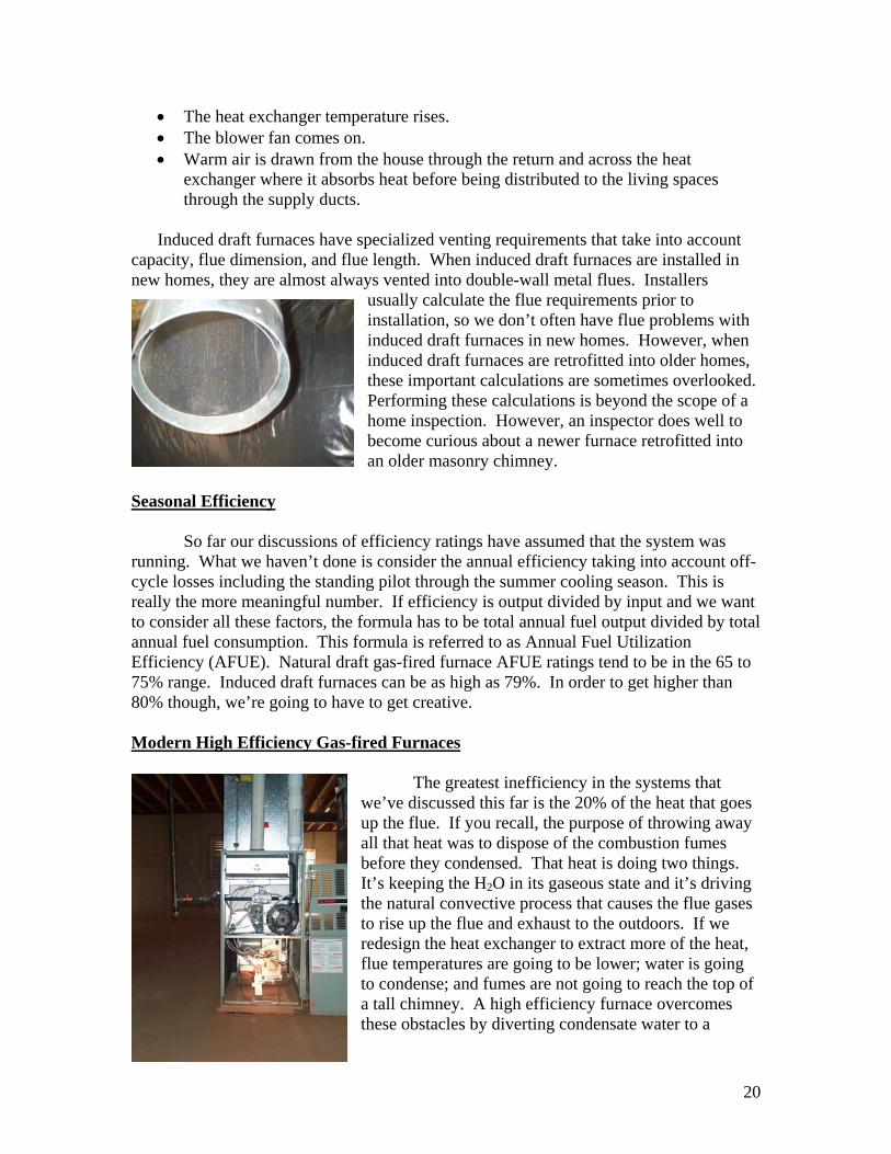
Induced draft furnaces have specialized venting requirements that take into account
capacity, flue dimension, and flue length. When induced draft furnaces are installed in new homes, they are almost always vented into double-wall metal flues. Installers
usually calculate the flue requirements prior to installation, so we don’t often have flue problems with induced draft furnaces in new homes. However, when induced draft furnaces are retrofitted into older homes, these important calculations are sometimes overlooked. Performing these calculations is beyond the scope of a home inspection. However, an inspector does well to become curious about a newer furnace retrofitted into an older masonry chimney.
Seasonal Efficiency So far our discussions of efficiency ratings have assumed that the system was running. What we haven’t done is consider the annual efficiency taking into account off-cycle losses including the standing pilot through the summer cooling season. This is really the more meaningful number. If efficiency is output divided by input and we want to consider all these factors, the formula has to be total annual fuel output divided by total annual fuel consumption. This formula is referred to as Annual Fuel Utilization Efficiency (AFUE). Natural draft gas-fired furnace AFUE ratings tend to be in the 65 to 75% range. Induced draft furnaces can be as high as 79%. In order to get higher than 80% though, we’re going to have to get creative. Modern High Efficiency Gas-fired Furnaces
The greatest inefficiency in the systems that we’ve discussed this far is the 20% of the heat that goes up the flue. If you recall, the purpose of throwing away all that heat was to dispose of the combustion fumes before they condensed. That heat is doing two things. It’s keeping the H2O in its gaseous state and it’s driving the natural convective process that causes the flue gases to rise up the flue and exhaust to the outdoors. If we redesign the heat exchanger to extract more of the heat, flue temperatures are going to be lower; water is going to condense; and fumes are not going to reach the top of a tall chimney. A high efficiency furnace overcomes these obstacles by diverting condensate water to a
20
drainage system and venting the flue through a side wall rather than through the roof. In fact, because flue temperatures are so low, these systems are vented through a plastic flue. Having taken that step, we tackle the next greatest inefficiency – makeup air. Rather than using house air for combustion, these new high efficiency systems draw makeup air in from the outdoors through a second plastic pipe. Modern high efficiency systems, commonly referred to as condensate furnaces, are typically more than 90% efficient. Heat lost through the flue is less than 10% of the total energy consumed. Because there are virtually no off-cycle losses, their AFUE rating is also over 90%. Oil-fired Natural gas is found in its gaseous state at room temperature. Because the gas is under pressure, it flows through the gas line. Flow is controlled by the pressure regulator and the control valve. Gas is mixed with air at the burner. Once it is lit, as long as the flow of gas continues, the flame persists.
Oil, on the other hand, is a liquid. Liquids don’t burn. When liquid fuels are used in combustion appliances, the fuel must be atomized before it is ignited. Our typical oil burning appliance has an electric motor driven pump that draws the oil from a storage tank. This pump in effect grinds the oil into microscopic particles, mixes it with air and sprays it across an electric spark igniter. As long as the oil continues to flow and the spark generator persists, the oil flame will continue to burn. This pump is called a burner motor.
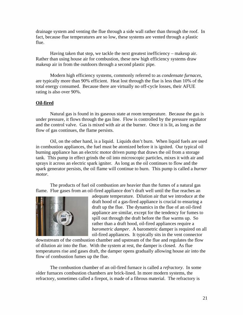
The products of fuel oil combustion are heavier than the fumes of a natural gas flame. Flue gases from an oil-fired appliance don’t draft well until the flue reaches an
adequate temperature. Dilution air that we introduce at the draft hood of a gas-fired appliance is crucial to ensuring a draft up the flue. The dynamics in the flue of an oil-fired appliance are similar, except for the tendency for fumes to spill out through the draft before the flue warms up. So rather than a draft hood, oil-fired appliances require a barometric damper. A barometric damper is required on all oil-fired appliances. It typically sits in the vent connector
downstream of the combustion chamber and upstream of the flue and regulates the flow of dilution air into the flue. With the system at rest, the damper is closed. As flue temperatures rise and gases draft, the damper opens gradually allowing house air into the flow of combustion fumes up the flue.
The combustion chamber of an oil-fired furnace is called a refractory. In some
older furnaces combustion chambers are brick-lined. In more modern systems, the refractory, sometimes called a firepot, is made of a fibrous material. The refractory is
21
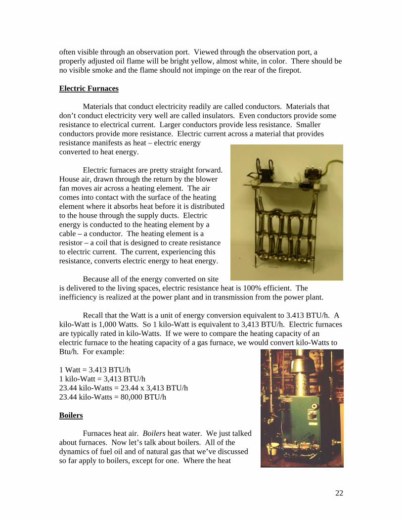
often visible through an observation port. Viewed through the observation port, a properly adjusted oil flame will be bright yellow, almost white, in color. There should be no visible smoke and the flame should not impinge on the rear of the firepot. Electric Furnaces Materials that conduct electricity readily are called conductors. Materials that don’t conduct electricity very well are called insulators. Even conductors provide some resistance to electrical current. Larger conductors provide less resistance. Smaller conductors provide more resistance. Electric current across a material that provides resistance manifests as heat – electric energy converted to heat energy.
Electric furnaces are pretty straight forward. House air, drawn through the return by the blower fan moves air across a heating element. The air comes into contact with the surface of the heating element where it absorbs heat before it is dto the house through the supply ducts. Electric energy is conducted to the heating element by a cable – a conductor. The heating element is a resistor – a coil that is designed to create resistance to electric current. The current, experiencing this resistance, converts electric energy to heat energy.
istributed
Because all of the energy converted on site
is delivered to the living spaces, electric resistance heat is 100% efficient. The inefficiency is realized at the power plant and in transmission from the power plant. Recall that the Watt is a unit of energy conversion equivalent to 3.413 BTU/h. A kilo-Watt is 1,000 Watts. So 1 kilo-Watt is equivalent to 3,413 BTU/h. Electric furnaces are typically rated in kilo-Watts. If we were to compare the heating capacity of an electric furnace to the heating capacity of a gas furnace, we would convert kilo-Watts to Btu/h. For example: 1 Watt = 3.413 BTU/h 1 kilo-Watt = 3,413 BTU/h 23.44 kilo-Watts = 23.44 x 3,413 BTU/h 23.44 kilo-Watts = 80,000 BTU/h Boilers
Furnaces heat air. Boilers heat water. We just talked about furnaces. Now let’s talk about boilers. All of the dynamics of fuel oil and of natural gas that we’ve discussed so far apply to boilers, except for one. Where the heat
22
exchanger of a combustion furnace surrounds the flame, the heat exchanger of a boiler is a container of water situated above the flame. A fossil fuel is mixed with air and is ignited. Chemical energy is converted to heat energy in a combustion process. Combustion fumes rise through the flue by natural convection. Heat radiates from the flame to the outside surface of the heat exchanger. Heat conducts through the wall of the heat exchanger and into the water.
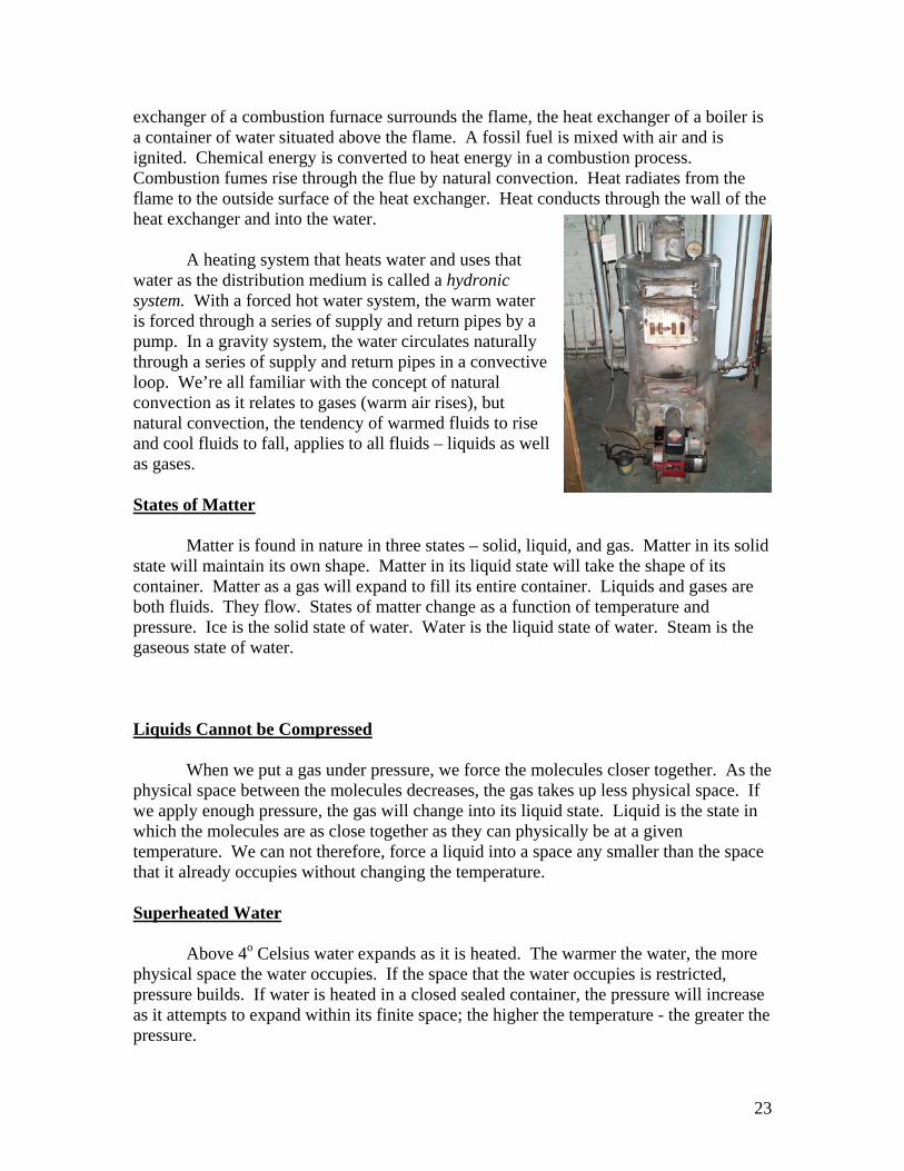
A heating system that heats water and uses that
water as the distribution medium is called a hydronic system. With a forced hot water system, the warm water is forced through a series of supply and return pipes by a pump. In a gravity system, the water circulates naturally through a series of supply and return pipes in a convective loop. We’re all familiar with the concept of natural convection as it relates to gases (warm air rises), but natural convection, the tendency of warmed fluids to rise and cool fluids to fall, applies to all fluids – liquids as well as gases. States of Matter Matter is found in nature in three states – solid, liquid, and gas. Matter in its solid state will maintain its own shape. Matter in its liquid state will take the shape of its container. Matter as a gas will expand to fill its entire container. Liquids and gases are both fluids. They flow. States of matter change as a function of temperature and pressure. Ice is the solid state of water. Water is the liquid state of water. Steam is the gaseous state of water. Liquids Cannot be Compressed When we put a gas under pressure, we force the molecules closer together. As the physical space between the molecules decreases, the gas takes up less physical space. If we apply enough pressure, the gas will change into its liquid state. Liquid is the state in which the molecules are as close together as they can physically be at a given temperature. We can not therefore, force a liquid into a space any smaller than the space that it already occupies without changing the temperature. Superheated Water Above 4o Celsius water expands as it is heated. The warmer the water, the more physical space the water occupies. If the space that the water occupies is restricted, pressure builds. If water is heated in a closed sealed container, the pressure will increase as it attempts to expand within its finite space; the higher the temperature - the greater the pressure.
23
At atmospheric pressure, the freezing point of water is 32o Fahrenheit and the
boiling point is 212o F. Note that we said that this is true at atmospheric pressure and we also said that states of matter change as a function of temperature and pressure. A few pages back we defined a BTU as a unit of energy equal to that required to raise the temperature of one pound of water one degree Fahrenheit. So if we begin with one pound of 32o water and we introduce 180 BTUs of heat energy, theoretically we get one pound of 212o water. Since the boiling point of water is 212o F. we would expect the water to begin to convert to steam at this point if we continue to add heat. However, if we put this water in a closed sealed container, we restrict the space that the water occupies and rather than expand into steam, the pressure simply builds. As the pressure builds, the boiling point rises. By the time the temperature rises above 212o, the boiling point has risen also, so the water does not boil and stays in its liquid state. As we continue to introduce heat, the temperature continues to rise. The boiling point goes up and the water still doesn’t expand to steam. Before long, we have water under pressure that is higher in temperature than 212o. We call liquid water that is hotter than 212o F. superheated water.
In a hydronic system, the water is contained in a closed loop – the heat exchanger, the distribution pipes, the radiators and the return pipes. As the temperature rises pressure builds. These systems are typically engineered such that temperatures are maintained between 165o and 185o F. – well below the 212o of boiling point. The water is heated in the boiler. Warm water is distributed throughout the house through supply pipes. Heat is released (water is cooled) at the radiators or convectors. Cooled water is returned to the boiler through return pipes. In order to maintain relatively constant pressure, these systems include an expansion tank in the water loop. Expansion Tank
An expansion tank is simply a container that is half full of water. The other half is full of air. Relatively constant pressure in the system is desirable. As the water heats, it expands. Without the expansion tank, pressure in the system is likely to rise above the desired pressure. With the expansion tank though, the water has a place to go. The water expands into the space occupied by the air. The air, being a gas, is compressed and the water pressure remains relatively constant.
In a gravity system the water is at atmospheric pressure and the expansion tank
must be located above the highest radiator – usually in the attic. In a forced hot water system, the water is maintained at a pressure between 12 and 20 pounds per square inch (PSI). The expansion tank must be located above the boiler – often between the floor joists in the basement ceiling.
Distribution Pump
Just as the defining difference between a forced air furnace and a gravity furnace
was the blower fan, the defining difference between a gravity boiler and a forced hot
24
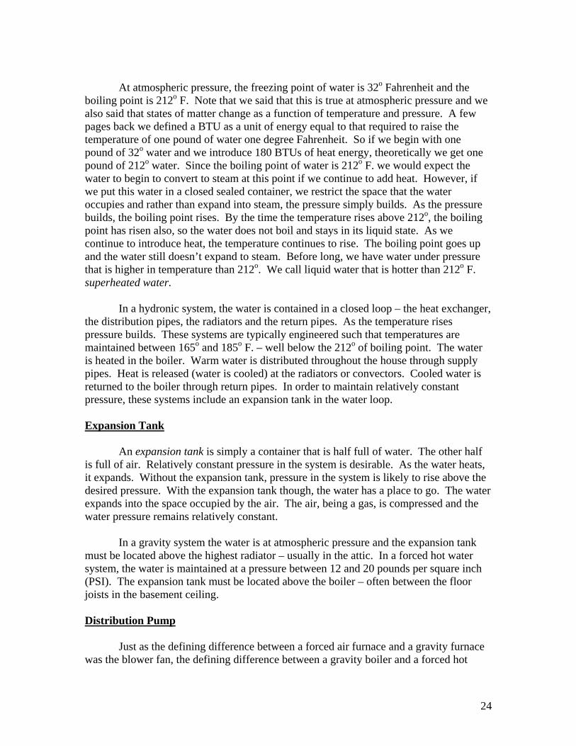
water boiler is a distribution pump. In order to extend its life, the distribution pump is usually installed on the return pipe where the water is cooler. But it realistically can be installed anywhere in the loop. Zones It is common to have more than one thermostat in a house. One thermostat controls heat delivered to one part of the house and another controls heat to another part of the house. We call these different parts of the house heat zones. With forced air systems it is common that each thermostat would be connected to a separate appliance. With water systems though, it is common for multiple thermostats to be connected to one boiler. A house with three zones, for instance, would have one boiler, three thermostats, and three distribution pumps. With this setup each thermostat will fire the boiler and control one distribution pump. Another approach to multiple zones includes one boiler, one distribution pump, and multiple zone valves with each valve controlled by one thermostat. Radiators Hot water enters a cast iron radiator. Heat was transferred from the boiler to the radiator by convection – natural convection in a gravity system, forced convection in a forced hot water system. Heat transfers from the water to the inside wall of the radiator by conduction. It transfers through the wall of the radiator by conduction. It transfers from the outside wall of the radiator to whatever air comes into contact with it by conduction. The warm air, being less dense and therefore lighter than the surrounding air, rises to the ceiling by natural convection. It reaches the ceiling, can’t move up any farther, and so begins to migrate across the ceiling, cooling as it goes. As the air cools, it becomes denser and therefore heavier than the warm air that follows it. The air eventually falls back to the floor where it is again drawn across the radiator, eventually coming into contact with the radiator and being reheated. The hot water in the radiator, giving up its heat to the air in the room, is cooled and returned to the boiler to be reheated. Yes there is some minor amount of radiant heat transfer from the outside surface of the radiator, but the term radiator really is a misnomer. Most of the heat transfer from the radiator to the room takes place as conduction between the air and the radiator. The warmed air is then circulated through the room in a convective loop.
25

Convectors Fin tube convectors work in much the same was as radiators. The pipe carries the hot water and the fins create the surface area for the air to come into contact with. Pressure Relief Valve We defined superheated water as water that had been heated to a temperature above 212o F. under pressure. We know that under normal operating conditions the water in a hydronic system is not allowed to get much over 185o F. However, things don’t always go as planned. So it is possible that a runaway system might heat water in the boiler faster than the heat is released at the radiators. In this case, it is possible that temperatures and pressures could rise above the design parameters. Should this happen, a boiler has the potential to very quickly become very dangerous. Super heated water within a container is exactly that – superheated water. However, superheated water is only superheated water as long as it remains in the container and under pressure where the boiling point is held at an artificially high level. Should the container fail the water that is released immediately finds atmospheric pressure. The boiling point suddenly drops to 212o, and the water in a sudden and dramatic flash expands to steam. In order to preclude this drama, hot water systems have pressure relief valves built into them. A pressure relief valve is a simple device that opens, releasing pressure from the system before pressure builds too high. In order to protect anyone who might be close by when the valve relieves, they must have an extension. The extension must be no smaller than the outlet of the valve. It must be of rigid material and it must not have threads on the end. Most manufacturers’ instructions call for the extension to terminate six inches above the floor. Pressure relief valves for hydronic systems are usually rated at 30 PSI. Pressure relief valves for steam systems are usually rated at 15 PSI. Steam Steam boilers are not unlike hot water boilers. In fact many boilers are manufactured for adaptation to either use. We recognize a steam boiler by the site glass that indicates the water level. Steam systems operate at higher temperatures but lower pressures than do hydronic systems. Steam is very light and very fluid. It moves itself readily through the distribution system by natural convection. There is therefore no need for a forced steam system. Gravity works fine. We do though have few issues specific to steam systems.
26

In our discussion of energy we established that a BTU was unit of energy equal to that required to raise the temperature of one pound of water one degree Fahrenheit. We also established that, at atmospheric pressure, the freezing point of water was 32o F. and that the boiling point is 212o F. By simple arithmetic, we easily illustrate that 180 BTUs would be required to raise the temperature of one pound of water from the freezing point to the boiling point. 212 – 32 = 180. We call this 180 BTUs sensible heat. We can sense the temperature change. If we start with one pound of 32o water and introduce 180
BTUs of heat energy, we raise the temperature of the water to 212o F. We now have 180 BTUs of energy in the form of heat stored in the water. If we continue to introduce heat, the water begins to convert to steam at a rate of 970 BTUs per pound. We call this 970 BTUs latent heat. It takes 1,150 BTUs of heat energy to convert one pound of 32o water to 212o steam. 180 BTUs are involved in temperature change (sensible heat). 970 BTUs are involved in the state change from liquid to gas (latent heat). In a hot water system, the entire distribution system is full of water. The expansion tank accommodates the thermal expansion and pressures are controlled within the design parameters. The thermal expansion that takes place as cool water becomes hot water is relatively minor. The thermal expansion that takes place as liquid water converts to steam however,
is much more significant. Containing the expansion within a steam system would be problematic. So between cycles, the distribution system opens itself up and allows house air into the radiators and distribution pipes. When the system fires it heats the water until it converts to steam. The steam being significantly lighter than the water in the system rises readily through the supply pipe to the radiator. The steam displaces the air in the system. Once the radiators are purged of air, a heat sensitive valve at each radiator closes and the system becomes a closed loop. Heat is transferred through the system by natural convection. Heat transfers from the water, to the inside wall of the radiator, through the wall of the radiator to the outside surface of the radiator, and into the air that comes into contact with the radiator by conduction. Heat is distributed through the living spaces in a convective loop. The steam being cooled condenses back to water releasing the latent heat.
27
In a 2-pipe steam system steam rises through supply pipes, releases its heat at the radiator, condenses to liquid and drips back to the boiler through the return pipe. In a single pipe system steam travels up and condensate water drips back through the same pipe. Glossary of Terms Automatic Safety Device A mechanism that responds automatically to a potentially dangerous condition for the purpose of avoiding some undesirable consequence. See normal operating control. Back Draft The phenomenon of combustion fumes spilling out through the draft hood rather than rising up the flue as intended. See Spillage. Boiler An architectural heating system that uses water as the distribution medium. Boiler (forced hot water) A boiler that employs a pump to push warm water through a series of supply and return pipes. Boiler (gravity) A heating system that allows warm water to circulate naturally through a series of supply and return pipes. Boiler (steam) A heating system that heats water until it converts to steam and then allows the steam to circulate through a series of distribution pipes. See Steam Boiler (single pipe) and Steam Boiler (2-pipe). Boiling Point The maximum temperature of liquid water. BTU An acronym that stands for British Thermal Unit, a unit of energy. One Btu is the amount of energy required to raise the temperature of one pound of water one degree Fahrenheit. BTU/h Btu per hour - A rate of energy transfer or conversion. Burner Motor A device that pumps fuel oil from a storage tank, atomizes it and sprays it over an igniter to accomplish combustion. Conduction A method of heat transfer whereby energy transfers through matter. Conductive heat transfer always manifests as migration from areas of high temperature to areas of low temperature. Convection A method of heat transfer whereby heated matter is move from one physical location to another. Convection always manifests in response to pressure differences with materials moving from areas of high pressure to areas of low pressure.
28
Convection (natural) A method of heat transfer whereby warmed fluids (gases or liquids) rise due to their natural buoyancy and cooled fluids fall do to their greater density. Convection (forced) A method of heat transfer whereby heated matter is moved by some external force. Distribution Pump The component of a forced hot water system that propels the water through the system. Downstream In the direction of flow. Draft Hood A opening at the top of the heat exchanger where dilution are is introduced. Efficiency The ratio output to input. Expansion Tank A container half full of water and half of air. As water heats is allowed to expand into the space occupied by the air, maintaining a relatively constant pressure in the water system. Fan/limit Switch An automatic safety control that turns the fan on and off or shuts the system down before it overheats. Flame Guard A cover (usually sheet metal) that covers the lower port of the heat exchanger. See Rollout shield. Flue A conduit for channeling combustion fumes out of a building. Forced Air Furnace A furnace that has a blower fan. Forced Convection See Convection (forced). Furnace A heating appliance that heats air. Gravity Furnace A furnace that does not have a blower fan. Heat exchanger (boiler) A water-filled (often cast iron, sometimes steel) container in which water is warmed. Combustion takes place below the heat exchanger. Heat transfers from the flame, through the wall of the heat exchanger, and into the water. Heat exchanger (furnace) The combustion chamber, usually sheet metal. Combustion is contained inside the heat exchanger. Air moves over the outside of the heat exchanger. Heat is transferred from the combustion inside the heat exchanger and through the wall of the heat exchanger, where it is absorbed by the air. Hot Surface Igniter (HSI) A type of electronic ignition.
29
Hydronic System A heating system that uses warm water as the distribution medium. Induced Draft A type of furnace that has an inducer fan. Inducer Fan A fan that sits in the flow of combustion fumes downstream of the heat exchanger and upstream of the vent connector. It provides dilution air and ensures a draft through the heat exchanger. Latent Heat Heat energy that is involved in state change. Natural Convection See Convection (natural). Off-cycle losses Inefficiencies that are realized when a system is at rest. Refractory The combustion chamber of an oil-fired appliance. Rollout Shield A cover (usually metal) that covers the lower port of the heat exchanger. See Flame Guard. Sensible Heat Heat energy that is realized as temperature. Service Switch A switch located near the heat plant that turns the system on and off. Shut-off Valve A valve located in the fuel line that stops the flow of fuel when closed. Steam Boiler (2-pipe) A heating system that allows steam to rise by natural convection through a supply pipe and allows condensate water to fall back to the boiler through a return pipe. Steam Boiler (single-pipe) A heating system that allows steam to rise by natural convection through a distribution pipe and allows condensate water to fall back to the boiler through the same pipe. Spillage The phenomenon of combustion fumes falling out through the draft hood rather than up the flue as intended. See back draft. Superheated Water Water that is higher in temperature than 212o under pressure. Therm A unit of energy equal to 100,000 Btu. Thermocouple A temperature sensor that sits in the pilot flame for the purpose confirming that the pilot is lit. A thermocouple is an automatic safety device. Thermostat The normal operating control for a heating system. A thermostat compares room temperature to a user selected set-point. When the temperature drops below the set-
30
point, the thermostat turns the system on. When the temperature rises above the set-point, the thermostat turns the system off. Upstream The direction opposite the direction of flow. See downstream. Vent Connector The conduit, usually sheet metal, that directs combustion fumes from an appliance to the flue.
31