Embed Size (px)
Citation preview
I IIIII I IIIII I IIIII I IIIII
PRINTED :
on the rod
Aluminium
Chrome plated steel
Depending to stroke
Connection
Working temperature range
Body material
Rod material
Min-Max Speed
Min-Max Speed with valves
Maximum force adjustable
Weight [gr] (at C=0 + weight 1mm CxC)
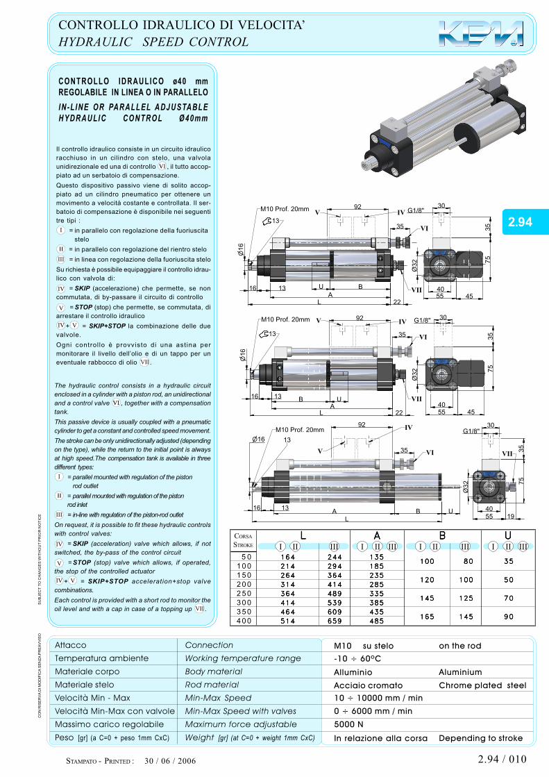
HYDRAULIC SPEED CONTROL
IN -L INE OR PARALLEL ADJUSTABLE
HYDRAULIC CONTROL Ø40mm
STROKE
The hydraulic control consists in a hydraulic circuit
enclosed in a cylinder with a piston rod, an unidirectional
and a control valve , together with a compensation
tank.
This passive device is usually coupled with a pneumatic
cylinder to get a constant and controlled speed movement.
The stroke can be only unidirectionally adjusted (depending
on the type), while the return to the initial point is always
at high speed.The compensation tank is available in three
different types:
= parallel mounted with regulation of the piston
rod outlet
= parallel mounted with regulation of the piston
rod inlet
= in-line with regulation of the piston-rod outlet
On request, it is possible to fit these hydraulic controls
with control valves:
= SKIP (acceleration) valve which allows, if not
switched, the by-pass of the control circuit
= STOP (stop) valve which allows, if operated,
the stop of the controlled actuator
+ = SKIP+STOP acceleration+stop valve
combinations.
Each control is provided with a short rod to monitor the
oil level and with a cap in case of a topping up .
SU
BJE
CT
TO
CH
AN
GE
S W
ITH
OU
T P
RIO
R N
OT
ICE
STAMPATO -
Attacco
Temperatura ambiente
Materiale corpo
Materiale stelo
Velocità Min - Max
Velocità Min-Max con valvole
Massimo carico regolabile
Peso [gr] (a C=0 + peso 1mm CxC)
M 10 su stelo
Alluminio
Acciaio cromato
In relazione alla corsa
CONTROLLO IDRAULICO DI VELOCITA’
CONTROLLO IDRAULICO ø40 mm
REGOLABILE IN LINEA O IN PARALLELO
CORSA
Il controllo idraulico consiste in un circuito idraulico
racchiuso in un cilindro con stelo, una valvola
unidirezionale ed una di controllo , il tutto accop-
piato ad un serbatoio di compensazione.
Questo dispositivo passivo viene di solito accop-
piato ad un cilindro pneumatico per ottenere un
movimento a velocità costante e controllata. Il ser-
batoio di compensazione è disponibile nei seguenti
tre tipi :
= in parallelo con regolazione della fuoriuscita
stelo
= in parallelo con regolazione del rientro stelo
= in linea con regolazione della fuoriuscita stelo
Su richiesta è possibile equipaggiare il controllo idrau-
lico con valvola di:
= SKIP (accelerazione) che permette, se non
commutata, di by-passare il circuito di controllo
= STOP (stop) che permette, se commutata, di
arrestare il controllo idraulico
+ = SKIP+STOP la combinazione delle due
valvole.
Ogni control lo è provvisto di una ast ina per
monitorare il livello dell’olio e di un tappo per un
eventuale rabbocco di olio .
CO
N R
ISE
RV
A D
I M
OD
IFIC
A S
EN
ZA
PR
EA
VV
ISO
-10 ÷ 60ºC
10 ÷ 10000 mm / min
0 ÷ 6000 mm / min
5000 N
164164164164164
214214214214214
264264264264264
314314314314314
364364364364364
414414414414414
464464464464464
514514514514514
50
100
150
200
250
300
350
400
244244244244244
294294294294294
364364364364364
414414414414414
489489489489489
539539539539539
609609609609609
659659659659659
135135135135135
185185185185185
235235235235235
285285285285285
335335335335335
385385385385385
435435435435435
485485485485485
8080808080
100100100100100
125125125125125
145145145145145
100100100100100
120120120120120
145145145145145
165165165165165
3535353535
5050505050
7070707070
9090909090
LLLLL AAAAA BBBBB UUUUU
30 / 06 / 2006
M10 Prof. 20mm
13
9 2
U B
A
1316
L 22
35
G 1/8 "30
35
75
4 555
4 0
V IV
VI
VII
16
32
Ø
16
30
35
9 2M10 Prof. 20mm
13
16 13B U
A
L 22
35
75
4 55532
Ø
4 0
G 1/8 "V IV
VI
VII
B U
L
16 13A
16
35
9 2
13
M10 Prof. 20mm IV
VVIIVI
1955
4 0
32
Ø
75
35
30G 1/8 "
2.94
2.94 / 010
OPERATING ON DEVICE IN M OTION FORBIDDEN.
This unit com plies with strict quality specifications.The incorrect use or m isuse of this unit will compro-m ise performance and will invalidate the warranty.THIS UNIT IS NOT A SAFETY DEVICE.
W arning before using this unit please ensure thatyou have made the correct port connection and thatthe unit is de-pressurised. W hen any maintenancework is done ensure the unit is also de-pressurised.
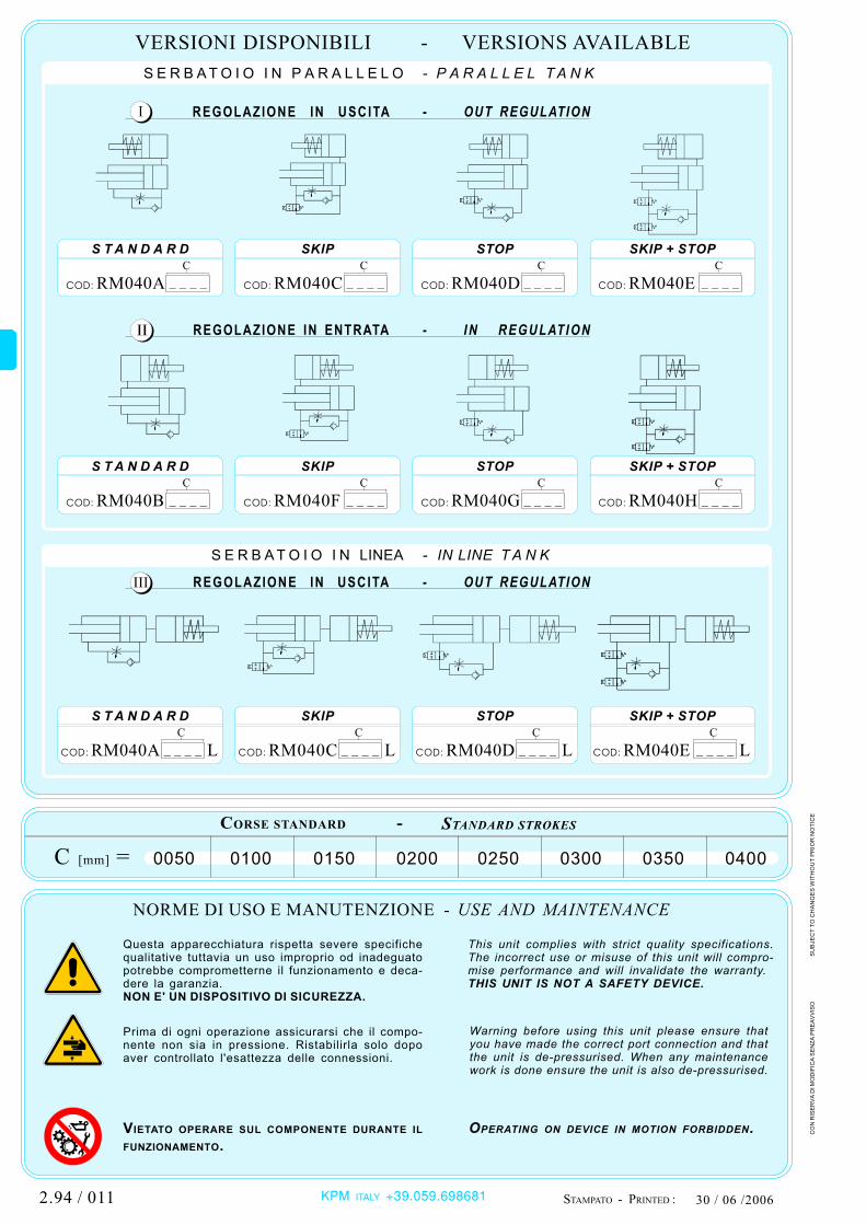
- VERSIONS AVAILABLE
USE AND MAINTENANCE
PRINTED :
- IN REGULATION
- OUT REGULATION
- OUT REGULATION
STANDARD STROKES
- P A R A LLE L T A N K
- IN LINE T A N K
SU
BJE
CT
TO
CH
AN
GE
S W
ITH
OU
T P
RIO
R N
OT
ICE
Questa apparecchiatura rispetta severe specifichequalitative tuttavia un uso improprio od inadeguatopotrebbe comprometterne il funzionamento e deca-dere la garanzia.NON E' UN DISPOSITIVO DI SICUREZZA.
Prima di ogni operazione assicurarsi che il compo-nente non sia in pressione. Ristabilirla solo dopoaver controllato l'esattezza delle connessioni.
VIETATO OPERARE SUL COM PONENTE DURANTE IL
FUNZIONAMENTO.
NORME DI USO E MANUTENZIONE -
STAMPATO -
VERSIONI DISPONIBILI
REGOLAZ IONE IN ENTRATA
REGOLAZ IONE IN U S C ITA
REGOLAZ IONE IN U S C ITA
CORSE STANDARD -
S E R B A T O I O I N P A R A L L E L O
S E R B A T O I O I N LINEA
CO
N R
ISE
RV
A D
I M
OD
IFIC
A S
EN
ZA
PR
EA
VV
ISO
0050 0100 0150 0200 0250 0300 0350 0400C [mm] =
S T A N D A R D SKIP STOP SKIP + STOP
S T A N D A R D SKIP STOP SKIP + STOP
S T A N D A R D SKIP STOP SKIP + STOP
30 / 06 /2006 KPM ITALY +39.059.698681
RM 040ACOD:
C
____ RM 040CCOD:
C
____ RM 040DCOD:
C
____ RM 040ECOD:
C
____
RM 040BCOD:
C
____ RM 040FCOD:
C
____ RM 040GCOD:
C
____ RM 040HCOD:
C
____
RM 040A LCOD:
C
____ COD:
C
____ COD:
C
____ COD:
C
____RM 040C L RM 040D L RM 040E L
2.94 / 011