Embed Size (px)
Citation preview
ControlLogix SystemCatalog Numbers 1756 series
Selection Guide
1756 ControlLogix I/O Modules
1756 ControlLogix Integrated Motion
1756 ControlLogix Communication Modules
1756 ControlLogix Controllers
1756 ControlLogix Chassis
1756 ControlLogix Power Supplies
2 Rockwell Automation Publication 1756-SG001R-EN-P - December 2012
ControlLogix System
Logix Controllers Comparison
Characteristic 1756 ControlLogix®1756-L71, 1756-L72, 1756-L73, 1756-L73XT, 1756-L74, 1756-L75
1756 GuardLogix®1756-L71S, 1756-L72S, 1756-L73S
1756 ControlLogix1756-L61, 1756-L62, 1756-L63, 1756-L63XT, 1756-L64, 1756-L65
1756 GuardLogix1756-L61S, 1756-L62S, 1756-L63S
CompactLogix™1769-L30ER, 1769-L30ER-NSE,
1769-L30ERM, 1769-L33ER, 1769-L33ERM, 1769-L36ERM
CompactLogix1769-L24ER-BB1B, 1769-L24ER-QBFC1B, 1769-L27ERM-QBFC1B
CompactLogix1769-L16ER-BB1B, 1769-L18ER-BB1B, 1769-L18ERM-BB1B
Controller tasks:• Continuous• Periodic• Event
• 32;• 100 programs/task
• 32;• 100 programs/task
• 32;• 100 programs/task
• 32;• 100 programs/task
• 32;• 100 programs/task
Event tasks All event triggers All event triggers Consumed tag, EVENT instruction triggers and motion events
Consumed tag, EVENT instruction triggers and motion events
Consumed tag, EVENT instruction triggers and motion events
User memory • 1756-L71: 2 MB • 1756-L72: 4 MB• 1756-L73: 8 MB
1756-L73XT: 8 MB• 1756-L74: 16 MB• 1756-L75: 32 MB• 1756-L71S: 2 MB + 1 MB safety• 1756-L72S: 4 MB +2 MB safety• 1756-L73S: 8 MB +4 MB safety
• 1756-L61: 2 MB• 1756-L62: 4 MB
1756-L63: 8 MB• 1756-L63XT: 8 MB
1756-L64: 16 MB• 1756-L65: 32 MB• 1756-L61S: 2 MB +1 MB safety• 1756-L62S: 4 MB +1 MB safety • 1756-L63S: 8 MB +3.75 MB safety
• 1769-L30ER, 1769-L30ER-NSE, 1769-L30ERM: 1MB
• 1769-L33ER, 1769-L33ERM: 2 MB
• 1769-L36ERM: 3 MB
• 1769-L24ER: 750 KB• 1769-L27ERM: 1 MB
• 1769-L16ER: 384 KB• 1769-L18ER,
1769-L18ERM: 512 KB
Memory card Secure Digital CompactFlash Secure Digital Secure Digital Secure Digital
Built-in ports 1 port USB 1 port RS-232 serial • Dual-port EtherNet/IP• 1 port USB
• Dual-port EtherNet/IP• 1 port USB
• Dual-port EtherNet/IP• 1 port USB
Communication options • EtherNet/IP• ControlNet• DeviceNet• Data Highway Plus• Remote I/O• SynchLink • USB
• EtherNet/IP • ControlNet• DeviceNet• Data Highway Plus• Remote I/O• SynchLink
• EtherNet/IP– Embedded switch– Single IP address
• DeviceNet• USB
• EtherNet/IP– Embedded switch– Single IP address
• DeviceNet• USB
• EtherNet/IP– Embedded switch– Single IP address
• USB
Controller connections 500 250 serial 256 256 256
Network connections Per network module:• 100 ControlNet (CN2/A)• 40 ControlNet (CNB)• 256 EtherNet/IP; 128 TCP (EN2x)• 128 EtherNet/IP; 64 TCP (ENBT)
Per network module:• 100 ControlNet (CN2/A)• 40 ControlNet (CNB)• 256 EtherNet/IP; 128 TCP (EN2x)• 128 EtherNet/IP; 64 TCP (ENBT)
• 1769-L30ER, 1769-L30ER-NSE, 1769-L30ERM: 16 EtherNet/IP; 120 TCP
• 1769-L33ER, 1769-L33ERM: 32 EtherNet/IP; 120 TCP
• 1769-L36ERM: 48 EtherNet/IP; 120 TCP
• 1769-L24ER-QB1B: 8 EtherNet/IP; 120 TCP
• 1769-24ER-BFC1B: 8 EtherNet/IP; 120 TCP
• 1769-L27ERM-QBFC1B: 16 EtherNet/IP; 120 TCP
• 1769-L16ER-BB1B 4 EtherNet/IP; 120 TCP
• 1769-L18ER-BB1B: 8 EtherNet/IP; 120 TCP
• 1769-L18ERM-BB1B: 8 EtherNet/IP; 120 TCP
Controller redundancy Full support Full support Backup via DeviceNet Backup via DeviceNet None
Simple motion • Stepper• Servo via DeviceNet• Analog or networked AC drive
• Stepper• Servo via DeviceNet• Analog or networked AC drive
• Servo via DeviceNet• Analog or Networked AC drive
• Servo via DeviceNet• Analog or Networked AC drive
Analog or Networked AC drive
Integrated motion • EtherNet/IP• SERCOS interface• Analog options:
– Encoder input– LDT input– SSI input
• EtherNet/IP• SERCOS interface• Analog options:
– Encoder input– LDT input– SSI input
EtherNet/IP:
1769-L30ERM, 1769-L33ERM, 1769-L36ERM
EtherNet/IP:
1769-L27-ERM-QBFC1B
EtherNet/IP:
1769-L18ERM-BB1B
Programming languages • Relay ladder• Structured text• Function block• Sequential function chart• Safety task: relay ladder, safety
application instructions
• Relay ladder• Structured text• Function block• Sequential function chart• Safety task: relay ladder, safety
application instructions
• Relay ladder• Structured text• Function block• Sequential function chart
• Relay ladder• Structured text• Function block• Sequential function chart
• Relay ladder• Structured text• Function block• Sequential function chart
Rockwell Automation Publication 1756-SG001R-EN-P - December 2012 3
ControlLogix System
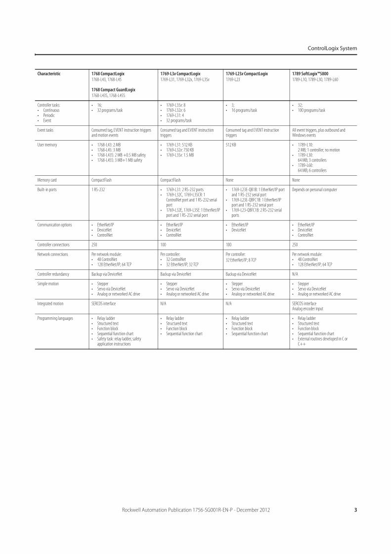
Characteristic 1768 CompactLogix1768-L43, 1768-L45
1768 Compact GuardLogix1768-L43S, 1768-L45S
1769-L3x CompactLogix1769-L31, 1769-L32x, 1769-L35x
1769-L23x CompactLogix1769-L23
1789 SoftLogix™58001789-L10, 1789-L30, 1789-L60
Controller tasks:• Continuous• Periodic• Event
• 16;• 32 programs/task
• 1769-L35x: 8 • 1769-L32x: 6• 1769-L31: 4 • 32 programs/task
• 3;• 16 programs/task
• 32;• 100 programs/task
Event tasks Consumed tag, EVENT instruction triggers and motion events
Consumed tag and EVENT instruction triggers
Consumed tag and EVENT instruction triggers
All event triggers, plus outbound and Windows events
User memory • 1768-L43: 2 MB• 1768-L45: 3 MB • 1768-L43S: 2 MB +0.5 MB safety• 1768-L45S: 3 MB+1 MB safety
• 1769-L31: 512 KB• 1769-L32x: 750 KB• 1769-L35x: 1.5 MB
512 KB • 1789-L10:2 MB; 1 controller; no motion
• 1789-L30:64 MB; 3 controllers
• 1789-L60:64 MB; 6 controllers
Memory card CompactFlash CompactFlash None None
Built-in ports 1 RS-232 • 1769-L31: 2 RS-232 ports• 1769-L32C, 1769-L35CR: 1
ControlNet port and 1 RS-232 serial port
• 1769-L32E, 1769-L35E: 1 EtherNet/IP port and 1 RS-232 serial port
• 1769-L23E-QB1B: 1 EtherNet/IP port and 1 RS-232 serial port
• 1769-L23E-QBFC1B: 1 EtherNet/IP port and 1 RS-232 serial port
• 1769-L23-QBFC1B: 2 RS-232 serial ports
Depends on personal computer
Communication options • EtherNet/IP• DeviceNet• ControlNet
• EtherNet/IP• DeviceNet • ControlNet
• EtherNet/IP• DeviceNet
• EtherNet/IP• DeviceNet• ControlNet
Controller connections 250 100 100 250
Network connections Per network module:• 48 ControlNet• 128 EtherNet/IP; 64 TCP
Per controller: • 32 ControlNet• 32 EtherNet/IP; 32 TCP
Per controller:
32 EtherNet/IP; 8 TCP
Per network module:• 48 ControlNet• 128 EtherNet/IP; 64 TCP
Controller redundancy Backup via DeviceNet Backup via DeviceNet Backup via DeviceNet N/A
Simple motion • Stepper• Servo via DeviceNet• Analog or networked AC drive
• Stepper• Servo via DeviceNet• Analog or networked AC drive
• Stepper• Servo via DeviceNet• Analog or networked AC drive
• Stepper• Servo via DeviceNet• Analog or networked AC drive
Integrated motion SERCOS interface N/A N/A SERCOS interfaceAnalog encoder input
Programming languages • Relay ladder• Structured text• Function block• Sequential function chart• Safety task: relay ladder, safety
application instructions
• Relay ladder• Structured text• Function block• Sequential function chart
• Relay ladder• Structured text• Function block• Sequential function chart
• Relay ladder• Structured text• Function block• Sequential function chart• External routines developed in C or
C++
4 Rockwell Automation Publication 1756-SG001R-EN-P - December 2012
ControlLogix System
Notes:
Rockwell Automation Publication 1756-SG001R-EN-P - December 2012 5
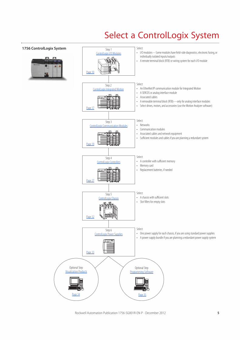
Select a ControlLogix SystemStep 1
ControlLogix I/O Modules
Step 2ControlLogix Integrated Motion
Step 3ControlLogix Communication Modules
1756 ControlLogix System
Step 4ControlLogix Controllers
Step 5ControlLogix Chassis
Step 6ControlLogix Power Supplies
Select:
• I/O modules—Some modules have field-side diagnostics, electronic fusing, or individually isolated inputs/outputs
• A remote terminal block (RTB) or wiring system for each I/O module
Select:
• An EtherNet/IP communication module for Integrated Motion
• A SERCOS or analog interface module
• Associated cables
• A removable terminal block (RTB)—only for analog interface modules
• Select drives, motors, and accessories (use the Motion Analyzer software)
Select:
• Networks
• Communication modules
• Associated cables and network equipment
• Sufficient modules and cables if you are planning a redundant system
Select:
• A controller with sufficient memory
• Memory card
• Replacement batteries, if needed
Select:
• A chassis with sufficient slots
• Slot fillers for empty slots
Select:
• One power supply for each chassis, if you are using standard power supplies
• A power supply bundle if you are planning a redundant power supply system
Optional StepProgramming Software
Optional StepVisualization Products
Page 10
Page 17
Page 19
Page 27
Page 32
Page 33
Page 34 Page 35
6 Rockwell Automation Publication 1756-SG001R-EN-P - December 2012
Select a ControlLogix System
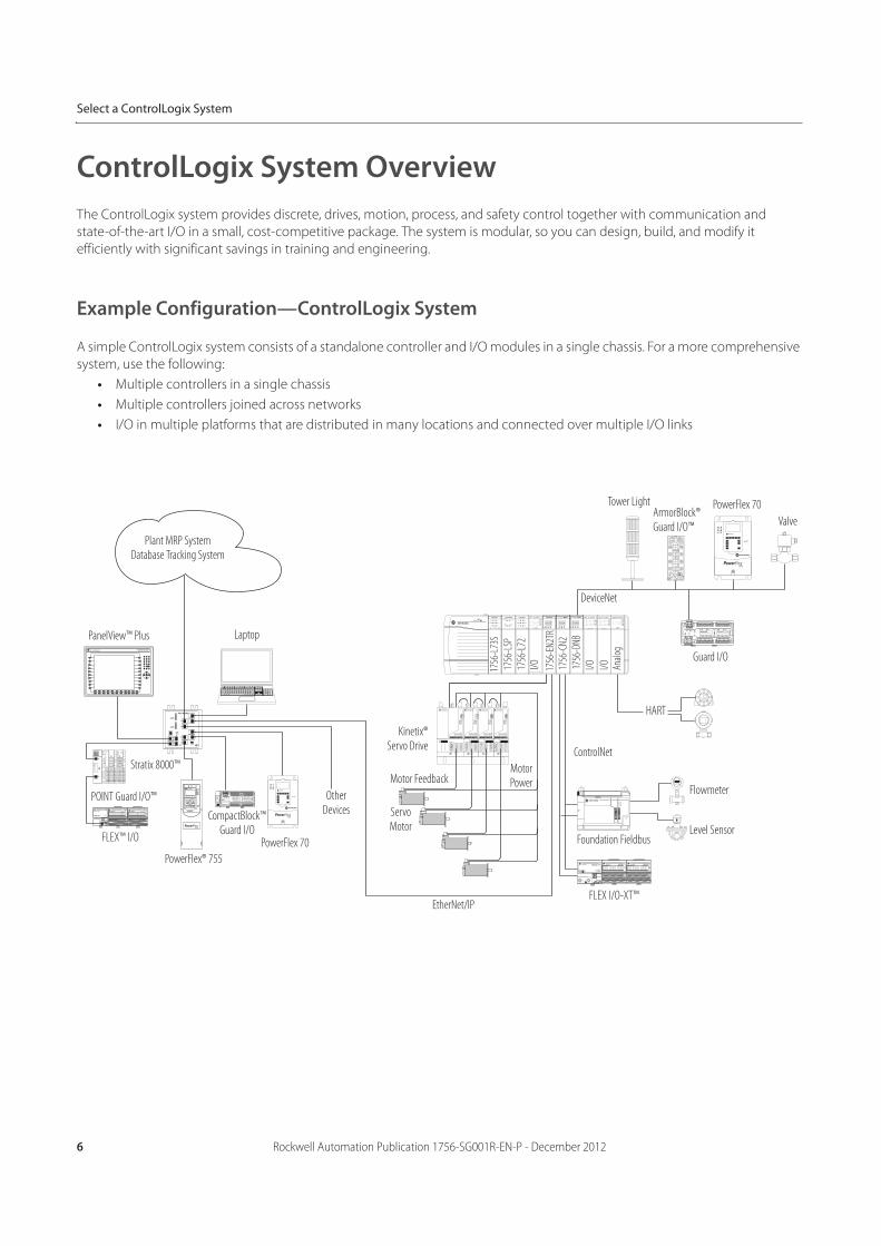
ControlLogix System Overview
The ControlLogix system provides discrete, drives, motion, process, and safety control together with communication and
state-of-the-art I/O in a small, cost-competitive package. The system is modular, so you can design, build, and modify it
efficiently with significant savings in training and engineering.
Example Configuration—ControlLogix System
A simple ControlLogix system consists of a standalone controller and I/O modules in a single chassis. For a more comprehensive
system, use the following:
• Multiple controllers in a single chassis
• Multiple controllers joined across networks
• I/O in multiple platforms that are distributed in many locations and connected over multiple I/O links
RUN I/O
RS232
OK
FORCE
BAT
RUN REM PROG
Logix5564
OKAB
OKI/OMOD/NET OKI/OMOD/NET
ST
ST
0 1 2 3 4 5 6 7
8 9 10 11 12 13 14 15
HART
ANALOG INPUT
OK
DIAGNOSTIC
FLT
ST
FLT
ST
0 1 2 3 4 5 6 7
0 1 2 3 4 5 6 7
8 9 10 11 12 13 14 15
8 9 10 11 12 13 14 15
DC OUTPUT
DIAGNOSTIC
FLT
ST
FLT
ST
0 1 2 3 4 5 6 7
0 1 2 3 4 5 6 7
8 9 10 11 12 13 14 15
8 9 10 11 12 13 14 15
DC INTPUT
POWER
STATUS
WDOG
BATT
NS
MODE
H1-1H1-2H1-3H1-4
755
98
2
5
0
3
6
7
1
4
Logix55LSP
SAFETY
RUN
SAFETY
TASK
BAT OK
RUN I/O
RS232
OK
FORCE
BAT
RUN REM PROG
Logix5561
DIAGNOSTIC
FLT
ST
FLT
ST
0 1 2 3 4 5 6 7
0 1 2 3 4 5 6 7
8 9 10 11 12 13 14 15
8 9 10 11 12 13 14 15
DC INTPUT
Plant MRP SystemDatabase Tracking System
Laptop
Stratix 8000™
POINT Guard I/O™
FLEX™ I/O
PanelView™ Plus
PowerFlex® 755
CompactBlock™ Guard I/O
PowerFlex 70
Other Devices
EtherNet/IP
Kinetix®Servo Drive
Motor Feedback
Servo Motor
Motor Power
DeviceNet
FLEX I/O-XT™
Tower LightArmorBlock® Guard I/O™
PowerFlex 70
Valve
Guard I/O
HART
ControlNet
Flowmeter
Level SensorFoundation Fieldbus
1756
-L73
S
1756
-LSP
1756
-L72
1756
-EN2
TR17
56-C
N2
1756
-DNB
I/O
I/O
Anal
og
I/O
Rockwell Automation Publication 1756-SG001R-EN-P - December 2012 7
Select a ControlLogix System
ControlLogix-XT System
ControlLogix-XT™ controllers function the same way as traditional ControlLogix controllers. The ControlLogix-XT products
include control and communication system components that are conformally coated to extend product life in harsh, corrosive
environments:
• When used with FLEX I/O-XT products, the ControlLogix-XT system can withstand temperatures range from -20…70 °C
(-4…158 °F).
• When used independently, the ControlLogix-XT system can withstand temperature ranges from -25...70 °C (-13…158 °F).
GuardLogix Safety System
A GuardLogix controller is a ControlLogix controller that also provides safety control. The GuardLogix system is a dual controller
solution—you must use a GuardLogix controller with the appropriate safety partner to achieve SIL 3/PLe/Cat. 4. A major benefit
of this system is that it is still a single project, safety, and standard together. The safety partner controller is a part of the system,
is automatically configured, and requires no user setup.
Application Description
Up to and including SIL 3 The GuardLogix controller system is type-approved and certified for use in safety applications up to and including SIL 3, according to IEC 61508, and applications up to and including category (PLe/Cat. 4), according to ISO 13849-1.
For more information, see the following:• GuardLogix Controllers Systems Safety Reference Manual, publication 1756-RM093• GuardLogix Controllers User Manual, publication 1756-UM020• GuardLogix Safety Application Instruction Set Reference Manual, publication 1756-RM095
SIL 2 Components of the ControlLogix system are type-approved and certified for use in SIL 2 applications, according to IEC 61508.
For a list of ControlLogix system components that meet SIL 2 requirements, see the Using ControlLogix in SIL 2 Applications Safety Reference Manual, publication 1756-RM001.
8 Rockwell Automation Publication 1756-SG001R-EN-P - December 2012
Select a ControlLogix System
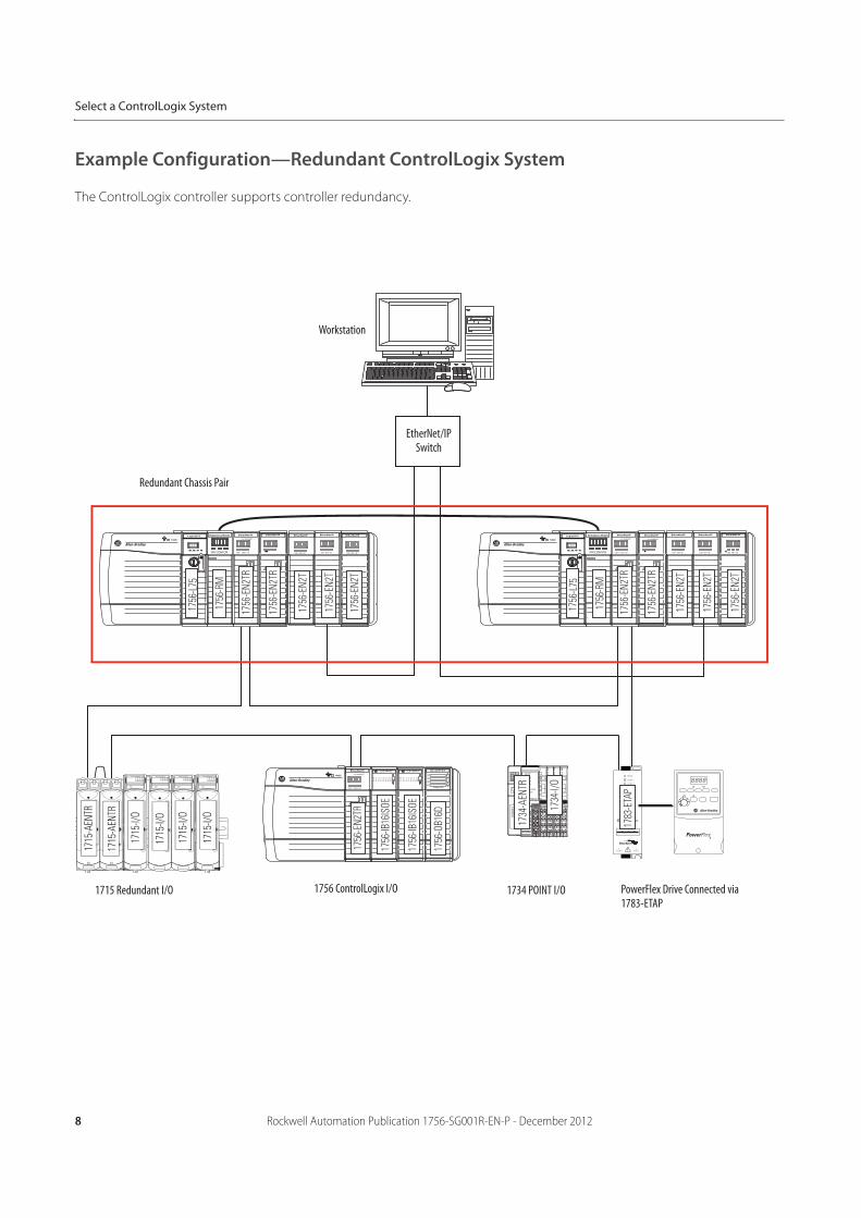
Example Configuration—Redundant ControlLogix System
The ControlLogix controller supports controller redundancy.
Redundant Chassis Pair
EtherNet/IP Switch
1756 ControlLogix I/O
Workstation
1715 Redundant I/O PowerFlex Drive Connected via 1783-ETAP
1734 POINT I/O
Rockwell Automation Publication 1756-SG001R-EN-P - December 2012 9
Select a ControlLogix System
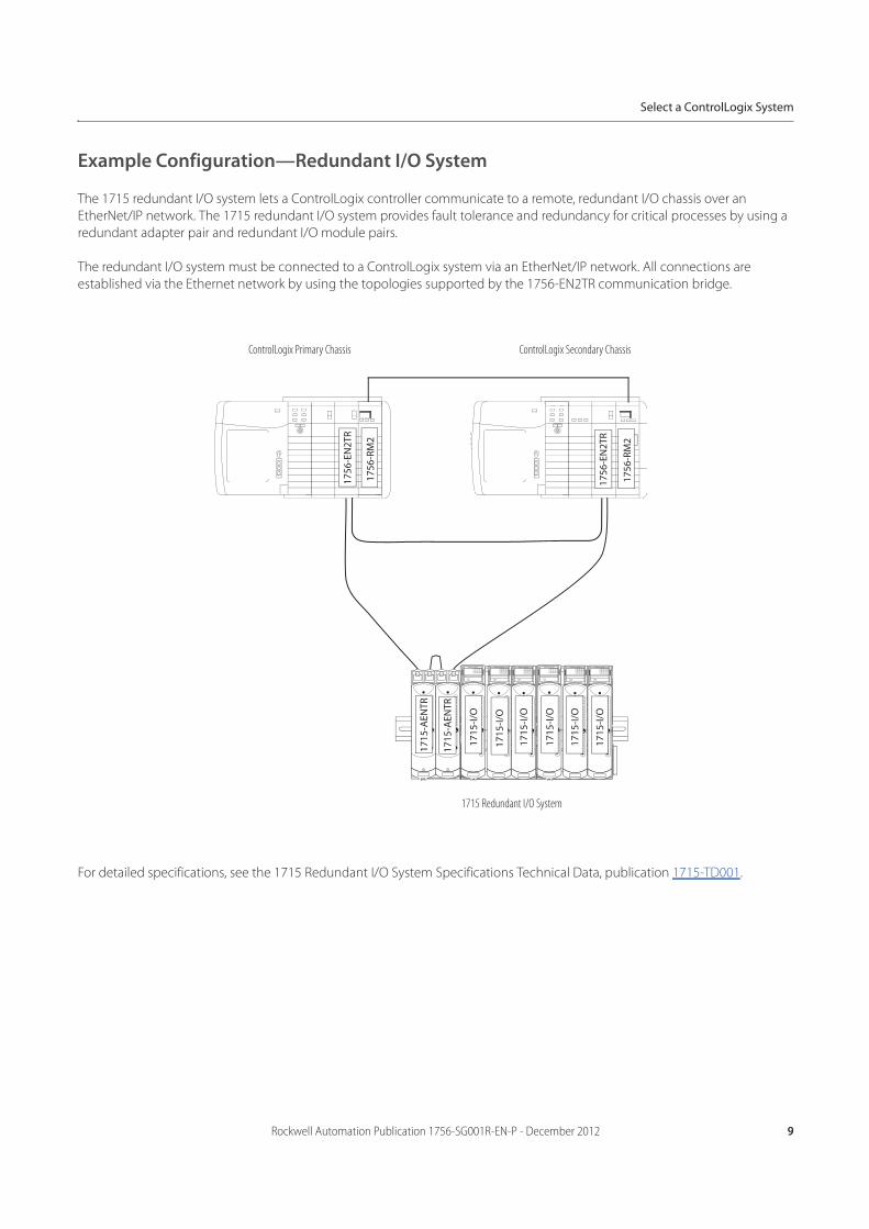
Example Configuration—Redundant I/O System
The 1715 redundant I/O system lets a ControlLogix controller communicate to a remote, redundant I/O chassis over an
EtherNet/IP network. The 1715 redundant I/O system provides fault tolerance and redundancy for critical processes by using a
redundant adapter pair and redundant I/O module pairs.
The redundant I/O system must be connected to a ControlLogix system via an EtherNet/IP network. All connections are
established via the Ethernet network by using the topologies supported by the 1756-EN2TR communication bridge.
For detailed specifications, see the 1715 Redundant I/O System Specifications Technical Data, publication 1715-TD001.
1756
-RM
2
1756
-EN
2TR
IO B
ASE
1715
-A31
0
CH1
CH1
CH1
CH1
CH1
CH1
CH1
CH1
TERMINAL IDENTITY
AOTADual.
CH1
CH1
CH1
CH1
CH1
CH1
CH1
CH1
TERMINAL IDENTITY
AOTADual.
CH1
CH1
CH1
CH1
CH1
CH1
CH1
CH1
TERMINAL IDENTITY
AOTADual.
IO B
ASE
1715
-A31
0
CH1
CH1
CH1
CH1
CH1
CH1
CH1
CH1
TERMINAL IDENTITY
AOTADual.
CH1
CH1
CH1
CH1
CH1
CH1
CH1
CH1
TERMINAL IDENTITY
AOTADual.
CH1
CH1
CH1
CH1
CH1
CH1
CH1
CH1
TERMINAL IDENTITY
AOTADual.
1715
-AEN
TR
1756
-EN
2TR
1756
-RM
2
1715
-AEN
TR
1715
-I/O
1715
-I/O
1715
-I/O
1715
-I/O
1715
-I/O
1715
-I/O
ControlLogix Primary Chassis ControlLogix Secondary Chassis
1715 Redundant I/O System
10 Rockwell Automation Publication 1756-SG001R-EN-P - December 2012
Select a ControlLogix System
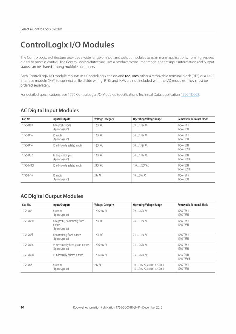
ControlLogix I/O Modules
The ControlLogix architecture provides a wide range of input and output modules to span many applications, from high-speed
digital to process control. The ControlLogix architecture uses a producer/consumer model so that input information and output
status can be shared among multiple controllers.
Each ControlLogix I/O module mounts in a ControlLogix chassis and requires either a removable terminal block (RTB) or a 1492
interface module (IFM) to connect all field-side wiring. RTBs and IFMs are not included with the I/O modules. They must be
ordered separately.
For detailed specifications, see 1756 ControlLogix I/O Modules Specifications Technical Data, publication 1756-TD002.
AC Digital Input Modules
AC Digital Output Modules
Cat. No. Inputs/Outputs Voltage Category Operating Voltage Range Removable Terminal Block
1756-IA8D 8 diagnostic inputs(4 points/group)
120V AC 79…132V AC 1756-TBNH1756-TBSH
1756-IA16 16 inputs(8 points/group)
120V AC 74…132V AC 1756-TBNH1756-TBSH
1756-IA16I 16 individually isolated inputs 120V AC 74…132V AC 1756-TBCH1756-TBS6H
1756-IA32 32 diagnostic inputs(4 points/group)
120V AC 74…132V AC 1756-TBCH1756-TBS6H
1756-IM16I 16 individually isolated inputs 240V AC 159…265V AC 1756-TBCH1756-TBS6H
1756-IN16 16 inputs(8 points/group)
24V AC 10…30V AC 1756-TBNH1756-TBSH
Cat. No. Inputs/Outputs Voltage Category Operating Voltage Range Removable Terminal Block
1756-OA8 8 outputs(4 points/group)
120/240V AC 79…265V AC 1756-TBNH1756-TBSH
1756-OA8D 8 diagnostic, electronically fused outputs(4 points/group)
120V AC 74…132V AC 1756-TBNH1756-TBSH
1756-OA8E 8 electronically fused outputs(4 points/group)
120V AC 74…132V AC 1756-TBNH1756-TBSH
1756-OA16 16 mechanically fused/group outputs(8 points/group)
120/240V AC 74…265V AC 1756-TBNH1756-TBSH
1756-OA16I 16 individually isolated outputs 120/240V AC 74…265V AC 1756-TBCH1756-TBS6H
1756-ON8 8 outputs(4 points/group)
24V AC 10…30V AC, current > 50 mA16…30V AC, current < 50 mA
1756-TBNH1756-TBSH
Rockwell Automation Publication 1756-SG001R-EN-P - December 2012 11
Select a ControlLogix System
DC Digital Input Modules
Cat. No. Inputs/Outputs Voltage Category Operating Voltage Range Removable Terminal Block
1756-IB16 16 inputs(8 points/group)
12/24V DC sink 10...31.2V DC 1756-TBNH1756-TBSH
1756-IB16D 16 diagnostic inputs(4 points/group)
12/24V DC sink 10...30V DC 1756-TBCH1756-TBS6H
1756-IB16I 16 individually isolated inputs 12/24V DC sink/source 10...30V DC 1756-TBCH1756-TBS6H
1756-IB16IF 16 high-speed, individually isolated inputs
12/24V DC sink/source 10…30V DC 1756-TBCH1756-TBS6H
1756-IB16ISOE 16 individually isolated, sequence of events inputs
24/48V DC sink/source 10...55V DC 1756-TBCH1756-TBS6H
1756-IB32 32 inputs(16 points/group)
12/24V DC sink 10...31.2V DC 1756-TBCH1756-TBS6H
1756-IC16 16 inputs(8 points/group)
48V DC sink 30...55V DC @ 60 °C (140 °C)30...60V DC @ 55 °C (131 °C)
1756-TBNH1756-TBSH
1756-IG16 16 inputs(8 points/group)
5V DC TTL source (Low = True) 4.5...5.5V DC 1756-TBNH1756-TBSH
1756-IH16I 16 individually isolated inputs 125V DC sink/source 90...146V DC 1756-TBCH1756-TBS6H
1756-IH16ISOE 16 individually isolated, sequence of events inputs
125V DC sink/source 90...140V DC 1756-TBCH1756-TBS6H
1756-IV16 16 inputs(8 points/group)
12/24V DC source 10...30V DC 1756-TBNH1756-TBSH
1756-IV32 32 inputs(16 points/group)
12/24V DC source 10...30V DC 1756-TBCH1756-TBS6H
12 Rockwell Automation Publication 1756-SG001R-EN-P - December 2012
Select a ControlLogix System
DC Digital Output Modules
Contact Output Modules
Cat. No. Inputs/Outputs Voltage Category Operating Voltage Range Removable Terminal Block
1756-OB8 8 outputs 12/24V DC source 10...30V DC 1756-TBNH1756-TBSH
1756-OB8EI 8 electronically fused, individually isolated outputs
12/24V DC source 10...30V DC 1756-TBCH1756-TBS6H
1756-OB8I 8 individually isolated outputs 12/24V DC source 10...30V DC 1756-TBCH1756-TBS6H
1756-OB16D 16 diagnostic outputs(8 points/group)
24V DC source 19.2...30V DC 1756-TBCH1756-TBS6H
1756-OB16E 16 electronically fused outputs(8 points/group)
12/24V DC source 10...31.2V DC 1756-TBNH1756-TBSH
1756-OB16I 16 individually isolated outputs 12/24V DC sink/source 10...30V DC 1756-TBCH1756-TBS6H
1756-OB16IEF 16 high-speed, individually isolated, electronically-fused outputs
24V DC sink/source 10...30V DC 1756-TBCH1756-TBS6H
1756-OB16IEFS 16 scheduled, high-speed, individually isolated, electronically-fused outputs
24V DC sink/source 10...30V DC 1756-TBCH1756-TBS6H
1756-OB16IS 16 individually isolated outputs8 scheduled outputs
12/24V DC sink/source 10...30V DC 1756-TBCH1756-TBS6H
1756-OB32 32 outputs(16 points/group)
12/24V DC source 10...31.2V DC 1756-TBCH1756-TBS6H
1756-OC8 8 outputs(4 points/group)
48V DC source 30...60V DC 1756-TBNH1756-TBSH
1756-OG16 16 (8 points/group) 5V DC TTL source (Low=True) 4.5...5.5V DC 1756-TBNH1756-TBSH
1756-OH8I 8 individually isolated outputs 120V DC 90...146V DC 1756-TBCH1756-TBS6H
1756-OV16E 16 electronically fused outputs(8 points/group)
12/24V DC sink 10...30V DC 1756-TBNH1756-TBSH
1756-OV32E 32 electronically fused outputs (16 points/group)
12/24V DC sink 10...30V DC 1756-TBCH1756-TBS6H
Cat. No. Inputs/Outputs Operating Voltage Range Removable Terminal Block
1756-OW16I 16 normally open, individually isolated outputs 5...150V DC10...265V AC
1756-TBCH1756-TBS6H
1756-OX8I 8 normally open8 normally closed, individually isolated outputs(2 points/group)
5...150V DC10...265V AC
1756-TBCH1756-TBS6H
Rockwell Automation Publication 1756-SG001R-EN-P - December 2012 13
Select a ControlLogix System
Analog Input Modules
Analog RTD and Thermocouple Modules
Cat. No. Inputs/Outputs Range Resolution Removable Terminal Block
1756-IF6CIS 6 individually isolated inputs, current sourcing 0…21 mA 16 bits0.34 μA/bit
1756-TBNH1756-TBSH
1756-IF6I 6 individually isolated inputs ±10.5V0…10.5V0…5.25V0…21 mA
16 bits10.5V: 343 μV/bit0…10.5V: 171 μV/bit0…5.25V: 86 μV/bit0…21 mA: 0.34 μA/bit
1756-TBNH1756-TBSH
1756-IF8 8 single-ended inputs4 differential inputs2 high-speed differential inputs
±10.25V0...10.25V0...5.125V0…20.5 mA
±10.25V: 320 μV/cnt (15 bits plus sign bipolar)0…10.25V: 160 μV/cnt (16 bits)0…5.125V: 80 μ/V cnt (16 bits)0…20.5 mA: 0.32 μA/cnt (16 bits)
1756-TBCH1756-TBS6H
1756-IF8H 8 differential voltage or current inputs, HART interface
±10V0...5V1…5V0...10V0…20 mA4…20 mA
16…21 bits 1756-TBCH1756-TBS6H
1756-IF16 16 single-ended inputs8 differential or 4 differential (high speed) inputs
±10.5V0…10.5V0…5.25V0…21 mA
16 bits10.5V: 343 μV/bit0…10.5V: 171 μV/bit0…5.25V: 86 μV/bit0…21 mA: 0.34 μA/bit
1756-TBCH1756-TBS6H
1756-IF16H 16 differential current inputs, HART interface 0…20 mA4…20 mA
16…21 bits 1756-TBCH1756-TBS6H
Cat. No. Inputs/Outputs Range Resolution Removable Terminal Block
1756-IR6I 6 individually isolated RTD inputs 1…487 Ω2…1000 Ω4…2000 Ω
8…4020 Ω
16 bits1…487 Ω: 7.7 mΩ/bit2…1000 Ω: 15 mΩ/bit4…2000 Ω: 30 mΩ/bit8…4020 Ω: 60 mΩ/bit
1756-TBNH1756-TBSH
1756-IT6I 6 individually isolated thermocouple inputs1 CJC
-12…78 mV-12…30 mV
16 bits-12...78 mV: 1.4 μV/bit-12...30 mV: 0.7 μV/bit
1756-TBNH1756-TBSH
1756-IT6I2 6 individually isolated thermocouple inputs2 CJC
-12…78 mV (1.4 μV per bit)
-12…30 mV (0.7 μV per bit, high-resolution range)
16 bits-12...78 mV: 1.4 μV/bit-12...30 mV: 0.7 μV/bit
1756-TBNH1756-TBSH
14 Rockwell Automation Publication 1756-SG001R-EN-P - December 2012
Select a ControlLogix System
Analog Output Modules
Analog Combination Input and Output Module
Specialty I/O Modules
Cat. No. Inputs/Outputs Range Resolution Removable Terminal Block
1756-OF4 4 voltage or current outputs ±10.4V0…21 mA
Voltage:15 bits across 10.5V, 320 μV/bit
Current:15 bits across 21 mA, 650 nA/bit
1756-TBNH1756-TBSH
1756-OF6CI 6 individually isolated outputs, current 0…21 mA 13 bits across 21 mA (2.7 μA) 1756-TBNH1756-TBSH
1756-OF6VI 6 individually isolated outputs, voltage ±10.5V 14 bits across 21V (1.3 mV)(13 bits across 10.5V +sign bit)
1756-TBNH1756-TBSH
1756-OF8 8 voltage or current outputs ±10.4V0…21 mA
15 bits across 21 mA - 650 nA/bit15 bits across 10.4V - 320 μV/bit
1756-TBNH1756-TBSH
1756-OF8H 8 voltage or current outputs, HART interface ±10.4V0…20 mA4…20 mA
15…16 bits 1756-TBNH1756-TBSH
Cat. No. Inputs/Outputs Range Resolution Removable Terminal Block
1756-IF4FXOF2F 4 high-speed, sub-millisecond, differential inputs
2 high-speed voltage or current outputs
Input:±10.5V0…10.5V0…5.25V0…21 mA
Output:±10.4V0…21 mA
Input:Approx. 14 bits across ±10V DC (21V total)±10V: 1.3 mV/bit, 14-bit effective0…10.5V: 1.3 mV/bit, 13-bit effective0…5.25V: 1.3 mV/bit, 12-bit effectiveApprox. 12 bits across 21 mA0…21 mA: 5.25 μA/bit
Output:13 bits across 21 mA = 2.8 μA/bit14 bits across 21.8V = 1.3 mV/bit
1756-TBCH1756-TBS6H
Cat. No. Inputs/Outputs Description Removable Terminal Block
1756-CFM 4 inputs (2 per channel)
2 outputs, current sourcing
Configurable flowmeter module
2 Flowmeter (F) inputs used for all modes2 Gate inputs used in Totalizer mode for prover/store count
1756-TBNH1756-TBSH
1756-HSC 2 counters, each with 3 inputs (A, B, Z for gate/reset)
4 outputs (2 points/group)
High-speed counter module
5V operation: 4.5…5.5V DC12/24V operation: 10…31.2V DC
1756-TBCH1756-TBS6H
1756-LSC8XIB8I 8…24V DC counters
8 high-speed 24V DC inputs
Low speed counter module
8…40 kHz 24V DC counters
8 high-speed 24V DC auxiliary inputs
1756-TBCH1756-TBS6H
1756-PLS Left section: 2 groups of 4 outputs and 4 inputs each
Center section: resolver interface and I/O control
Right section: 2 groups of 4 outputs and 4 inputs each
Programmable limit switch module Requires 3 RTBs: 1756-TBNH or 1756-TBSH
Rockwell Automation Publication 1756-SG001R-EN-P - December 2012 15
Select a ControlLogix System
HART Smart Instrumentation
HART (Highway Addressable Remote Transmitter) is an open protocol designed to connect analog devices. For HART
connectivity, select products available from Rockwell Automation and our Encompass™ partners.
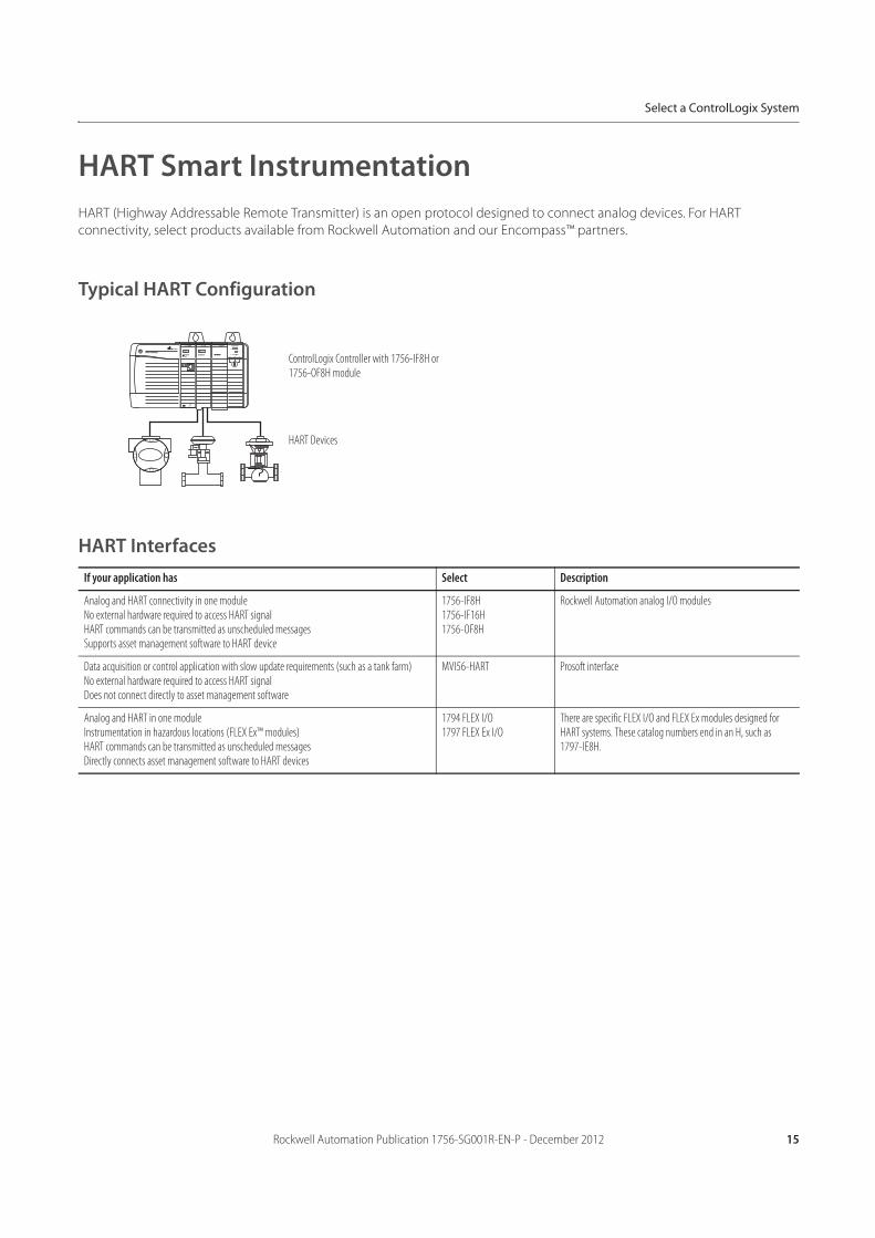
Typical HART Configuration
HART Interfaces
If your application has Select Description
Analog and HART connectivity in one moduleNo external hardware required to access HART signalHART commands can be transmitted as unscheduled messagesSupports asset management software to HART device
1756-IF8H1756-IF16H1756-OF8H
Rockwell Automation analog I/O modules
Data acquisition or control application with slow update requirements (such as a tank farm)No external hardware required to access HART signalDoes not connect directly to asset management software
MVI56-HART Prosoft interface
Analog and HART in one moduleInstrumentation in hazardous locations (FLEX Ex™ modules)HART commands can be transmitted as unscheduled messagesDirectly connects asset management software to HART devices
1794 FLEX I/O1797 FLEX Ex I/O
There are specific FLEX I/O and FLEX Ex modules designed for HART systems. These catalog numbers end in an H, such as 1797-IE8H.
HART Devices
ControlLogix Controller with 1756-IF8H or 1756-OF8H module
16 Rockwell Automation Publication 1756-SG001R-EN-P - December 2012
Select a ControlLogix System
Accessories—I/O Modules
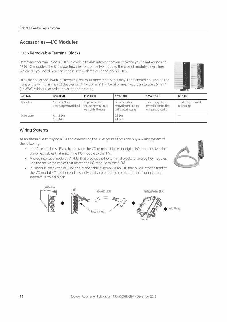
1756 Removable Terminal Blocks
Removable terminal blocks (RTBs) provide a flexible interconnection between your plant wiring and
1756 I/O modules. The RTB plugs into the front of the I/O module. The type of module determines
which RTB you need. You can choose screw-clamp or spring-clamp RTBs.
RTBs are not shipped with I/O modules. You must order them separately. The standard housing on the
front of the wiring arm is not deep enough for 2.5 mm2 (14 AWG) wiring. If you plan to use 2.5 mm2
(14 AWG) wiring, also order the extended housing.
Wiring Systems
As an alternative to buying RTBs and connecting the wires yourself, you can buy a wiring system of
the following:
• Interface modules (IFMs) that provide the I/O terminal blocks for digital I/O modules. Use the
pre-wired cables that match the I/O module to the IFM.
• Analog interface modules (AIFMs) that provide the I/O terminal blocks for analog I/O modules.
Use the pre-wired cables that match the I/O module to the AIFM.
• I/O module-ready cables. One end of the cable assembly is an RTB that plugs into the front of
the I/O module. The other end has individually color-coded conductors that connect to a
standard terminal block.
Attribute 1756-TBNH 1756-TBSH 1756-TBCH 1756-TBS6H 1756-TBE
Description 20-position NEMA screw-clamp removable block
20-pin spring-clamp removable terminal block with standard housing
36-pin cage-clamp removable terminal block with standard housing
36-pin spring-clamp removable terminal block with standard housing
Extended depth terminal block housing
Screw torque 0.8…1 N•m7…9 lb•in
0.4 N•m4.4 lb•in
—
I/O ModuleRTB Pre-wired Cable
Factory-wired
Interface Module (IFM)
Field Wiring
Rockwell Automation Publication 1756-SG001R-EN-P - December 2012 17
Select a ControlLogix System
ControlLogix Integrated Motion
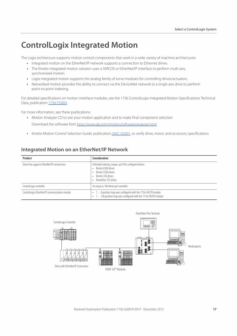
The Logix architecture supports motion control components that work in a wide variety of machine architectures:
• Integrated motion on the EtherNet/IP network supports a connection to Ethernet drives.
• The Kinetix integrated-motion solution uses a SERCOS or EtherNet/IP interface to perform multi-axis,
synchronized motion.
• Logix integrated motion supports the analog family of servo modules for controlling drives/actuators.
• Networked motion provides the ability to connect via the DeviceNet network to a single axis drive to perform
point-to-point indexing.
For detailed specifications on motion interface modules, see the 1756 ControlLogix Integrated Motion Specifications Technical
Data, publication 1756-TD004.
For more information, see these publications:
• Motion Analyzer CD to size your motion application and to make final component selection
Download the software from http://www.ab.com/motion/software/analyzer.html
• Kinetix Motion Control Selection Guide, publication GMC-SG001, to verify drive, motor, and accessory specifications
Integrated Motion on an EtherNet/IP Network
Product Consideration
Drive that supports EtherNet/IP connections Unlimited velocity, torque, and VHz configured drives:• Kinetix 6500 drives• Kinetix 5500 drives• Kinetix 350 drives• PowerFlex 755 drives
ControlLogix controller As many as 100 drives per controller
ControlLogix EtherNet/IP communication module • 1…8 position loop axes configured with the 1756-EN2TR module• 1…128 position loop axes configured with the 1756-EN3TR module
ControlLogix Controller
PanelView Plus Terminal
Workstations
POINT I/O™ ModulesDrive with EtherNet/IP Connection
18 Rockwell Automation Publication 1756-SG001R-EN-P - December 2012
Select a ControlLogix System
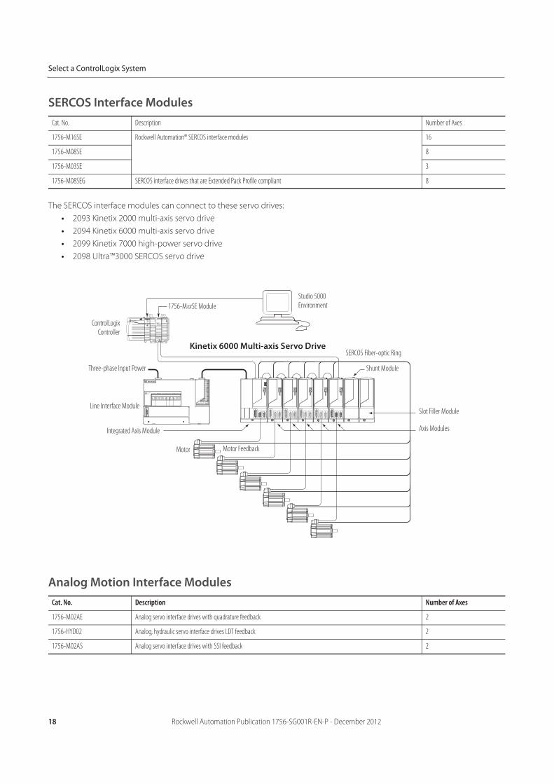
SERCOS Interface Modules
The SERCOS interface modules can connect to these servo drives:
• 2093 Kinetix 2000 multi-axis servo drive
• 2094 Kinetix 6000 multi-axis servo drive
• 2099 Kinetix 7000 high-power servo drive
• 2098 Ultra™3000 SERCOS servo drive
Analog Motion Interface Modules
Cat. No. Description Number of Axes
1756-M16SE Rockwell Automation® SERCOS interface modules 16
1756-M08SE 8
1756-M03SE 3
1756-M08SEG SERCOS interface drives that are Extended Pack Profile compliant 8
Cat. No. Description Number of Axes
1756-M02AE Analog servo interface drives with quadrature feedback 2
1756-HYD02 Analog, hydraulic servo interface drives LDT feedback 2
1756-M02AS Analog servo interface drives with SSI feedback 2
Studio 5000 Environment1756-MxxSE Module
ControlLogixController
Three-phase Input Power
Line Interface Module
Integrated Axis Module
Motor Motor Feedback
Axis Modules
Slot Filler Module
Shunt Module
SERCOS Fiber-optic RingKinetix 6000 Multi-axis Servo Drive
Rockwell Automation Publication 1756-SG001R-EN-P - December 2012 19
Select a ControlLogix System
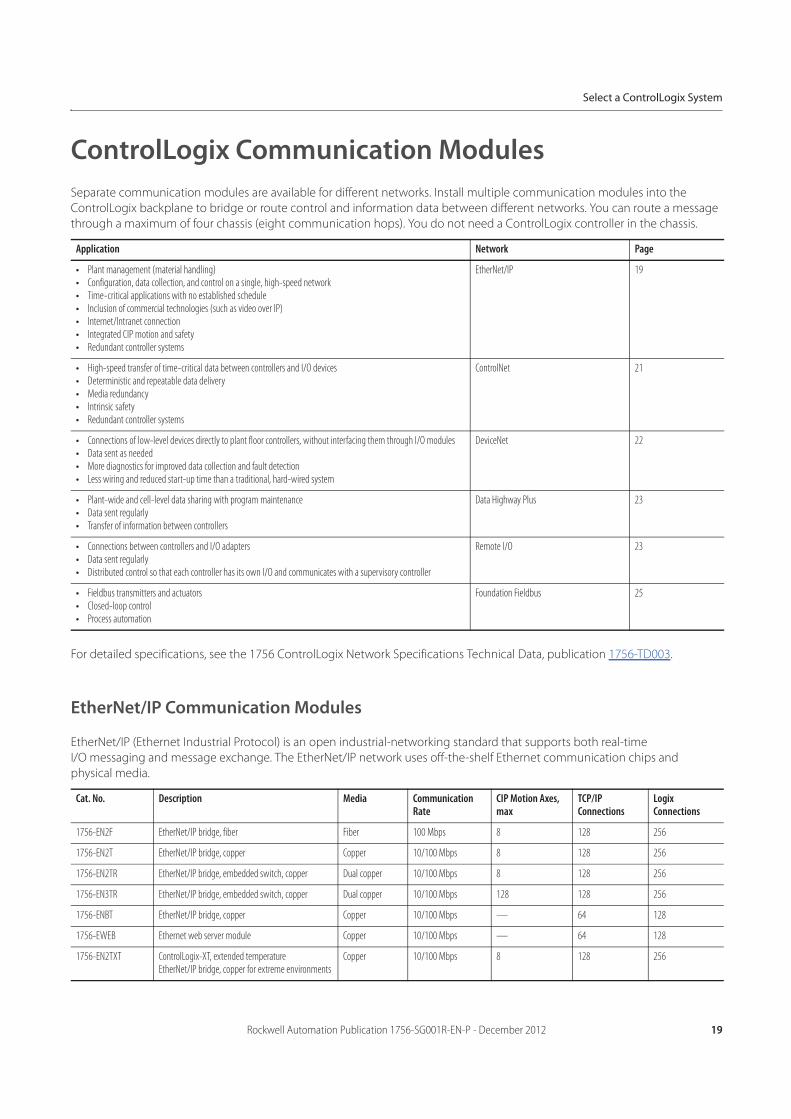
ControlLogix Communication Modules
Separate communication modules are available for different networks. Install multiple communication modules into the
ControlLogix backplane to bridge or route control and information data between different networks. You can route a message
through a maximum of four chassis (eight communication hops). You do not need a ControlLogix controller in the chassis.
For detailed specifications, see the 1756 ControlLogix Network Specifications Technical Data, publication 1756-TD003.
EtherNet/IP Communication Modules
EtherNet/IP (Ethernet Industrial Protocol) is an open industrial-networking standard that supports both real-time
I/O messaging and message exchange. The EtherNet/IP network uses off-the-shelf Ethernet communication chips and
physical media.
Application Network Page
• Plant management (material handling)• Configuration, data collection, and control on a single, high-speed network• Time-critical applications with no established schedule• Inclusion of commercial technologies (such as video over IP)• Internet/Intranet connection• Integrated CIP motion and safety• Redundant controller systems
EtherNet/IP 19
• High-speed transfer of time-critical data between controllers and I/O devices• Deterministic and repeatable data delivery• Media redundancy• Intrinsic safety• Redundant controller systems
ControlNet 21
• Connections of low-level devices directly to plant floor controllers, without interfacing them through I/O modules• Data sent as needed• More diagnostics for improved data collection and fault detection• Less wiring and reduced start-up time than a traditional, hard-wired system
DeviceNet 22
• Plant-wide and cell-level data sharing with program maintenance• Data sent regularly• Transfer of information between controllers
Data Highway Plus 23
• Connections between controllers and I/O adapters• Data sent regularly• Distributed control so that each controller has its own I/O and communicates with a supervisory controller
Remote I/O 23
• Fieldbus transmitters and actuators• Closed-loop control• Process automation
Foundation Fieldbus 25
Cat. No. Description Media Communication Rate
CIP Motion Axes, max
TCP/IP Connections
Logix Connections
1756-EN2F EtherNet/IP bridge, fiber Fiber 100 Mbps 8 128 256
1756-EN2T EtherNet/IP bridge, copper Copper 10/100 Mbps 8 128 256
1756-EN2TR EtherNet/IP bridge, embedded switch, copper Dual copper 10/100 Mbps 8 128 256
1756-EN3TR EtherNet/IP bridge, embedded switch, copper Dual copper 10/100 Mbps 128 128 256
1756-ENBT EtherNet/IP bridge, copper Copper 10/100 Mbps — 64 128
1756-EWEB Ethernet web server module Copper 10/100 Mbps — 64 128
1756-EN2TXT ControlLogix-XT, extended temperature EtherNet/IP bridge, copper for extreme environments
Copper 10/100 Mbps 8 128 256
20 Rockwell Automation Publication 1756-SG001R-EN-P - December 2012
Select a ControlLogix System
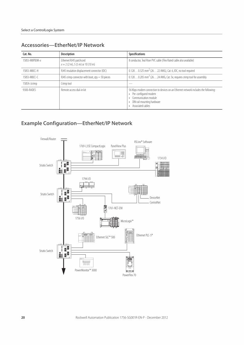
Accessories—EtherNet/IP Network
Example Configuration—EtherNet/IP Network
Cat. No. Description Specifications
1585J-M8PBJM-x Ethernet RJ45 patchcordx = 2 (2 m), 5 (5 m) or 10 (10 m)
8 conductor, Teal Riser PVC cable (Flex Rated cable also available)
1585J-M8CC-H RJ45 insulation displacement connector (IDC) 0.128…0.325 mm2 (26…22 AWG), Cat. 6, IDC, no tool required
1585J-M8CC-C RJ45 crimp connector with boot, qty = 50 pieces 0.128…0.205 mm2 (26…24 AWG, Cat. 5e, requires crimp tool for assembly
1585A-Jcrimp Crimp tool —
9300-RADES Remote access dial-in kit 56 Kbps modem connection to devices on an Ethernet network includes the following:• Pre-configured modem• Communication module• DIN rail mounting hardware• Associated cables
Firewall/Router
Stratix Switch
Stratix Switch
Stratix Switch
PowerMonitor™ 3000
PowerFlex 70
Ethernet PLC-5®
MicroLogix™
Ethernet SLC™ 500
1756 I/O
1794 I/O
1761-NET-ENI
ControlNet
DeviceNet
1734 I/O
RSLinx® Software
PanelView Plus1769-L35E CompactLogix
Rockwell Automation Publication 1756-SG001R-EN-P - December 2012 21
Select a ControlLogix System
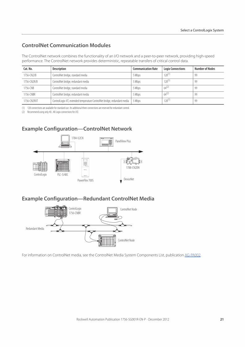
ControlNet Communication Modules
The ControlNet network combines the functionality of an I/O network and a peer-to-peer network, providing high-speed
performance. The ControlNet network provides deterministic, repeatable transfers of critical control data.
Example Configuration—ControlNet Network
Example Configuration—Redundant ControlNet Media
For information on ControlNet media, see the ControlNet Media System Components List, publication AG-PA002.
Cat. No. Description Communication Rate Logix Connections Number of Nodes
1756-CN2/B ControlNet bridge, standard media 5 Mbps 128(1)
(1) 128 connections are available for standard use. An additional three connections are reserved for redundant control.
99
1756-CN2R/B ControlNet bridge, redundant media 5 Mbps 128(1) 99
1756-CNB ControlNet bridge, standard media 5 Mbps 64(2)
(2) Recommend using only 40...48 Logix connections for I/O.
99
1756-CNBR ControlNet bridge, redundant media 5 Mbps 64(2) 99
1756-CN2RXT ControlLogix-XT, extended temperature ControlNet bridge, redundant media 5 Mbps 128(1) 99
1784-U2CNPanelView Plus
1788-CN2DN
DeviceNetPowerFlex 700S
PLC-5/40CControlLogix
Redundant Media
ControlLogix
1756-CNBRControlNet Node
ControlNet Node
22 Rockwell Automation Publication 1756-SG001R-EN-P - December 2012
Select a ControlLogix System
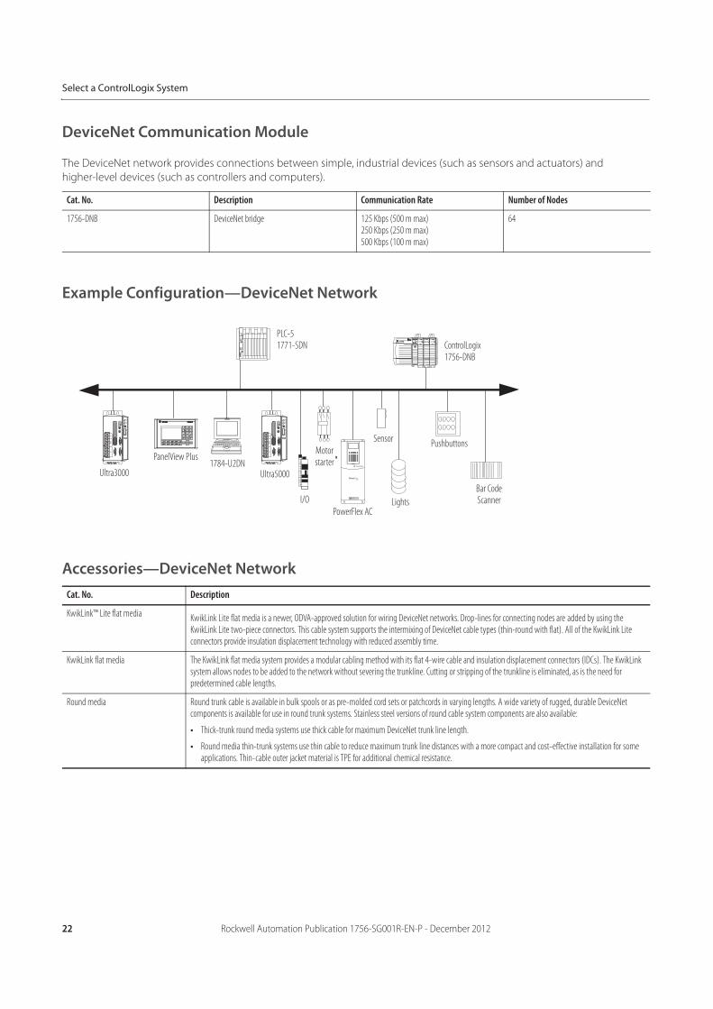
DeviceNet Communication Module
The DeviceNet network provides connections between simple, industrial devices (such as sensors and actuators) and
higher-level devices (such as controllers and computers).
Example Configuration—DeviceNet Network
Accessories—DeviceNet Network
Cat. No. Description Communication Rate Number of Nodes
1756-DNB DeviceNet bridge 125 Kbps (500 m max)250 Kbps (250 m max)500 Kbps (100 m max)
64
Cat. No. Description
KwikLink™ Lite flat media KwikLink Lite flat media is a newer, ODVA-approved solution for wiring DeviceNet networks. Drop-lines for connecting nodes are added by using the KwikLink Lite two-piece connectors. This cable system supports the intermixing of DeviceNet cable types (thin-round with flat). All of the KwikLink Lite connectors provide insulation displacement technology with reduced assembly time.
KwikLink flat media The KwikLink flat media system provides a modular cabling method with its flat 4-wire cable and insulation displacement connectors (IDCs). The KwikLink system allows nodes to be added to the network without severing the trunkline. Cutting or stripping of the trunkline is eliminated, as is the need for predetermined cable lengths.
Round media Round trunk cable is available in bulk spools or as pre-molded cord sets or patchcords in varying lengths. A wide variety of rugged, durable DeviceNet components is available for use in round trunk systems. Stainless steel versions of round cable system components are also available:
• Thick-trunk round media systems use thick cable for maximum DeviceNet trunk line length.
• Round media thin-trunk systems use thin cable to reduce maximum trunk line distances with a more compact and cost-effective installation for some applications. Thin-cable outer jacket material is TPE for additional chemical resistance.
PLC-51771-SDN ControlLogix
1756-DNB
Ultra3000
PanelView Plus1784-U2DN
Ultra5000
I/O
Motor starter
PowerFlex AC
SensorPushbuttons
Lights
Bar Code Scanner
Rockwell Automation Publication 1756-SG001R-EN-P - December 2012 23
Select a ControlLogix System
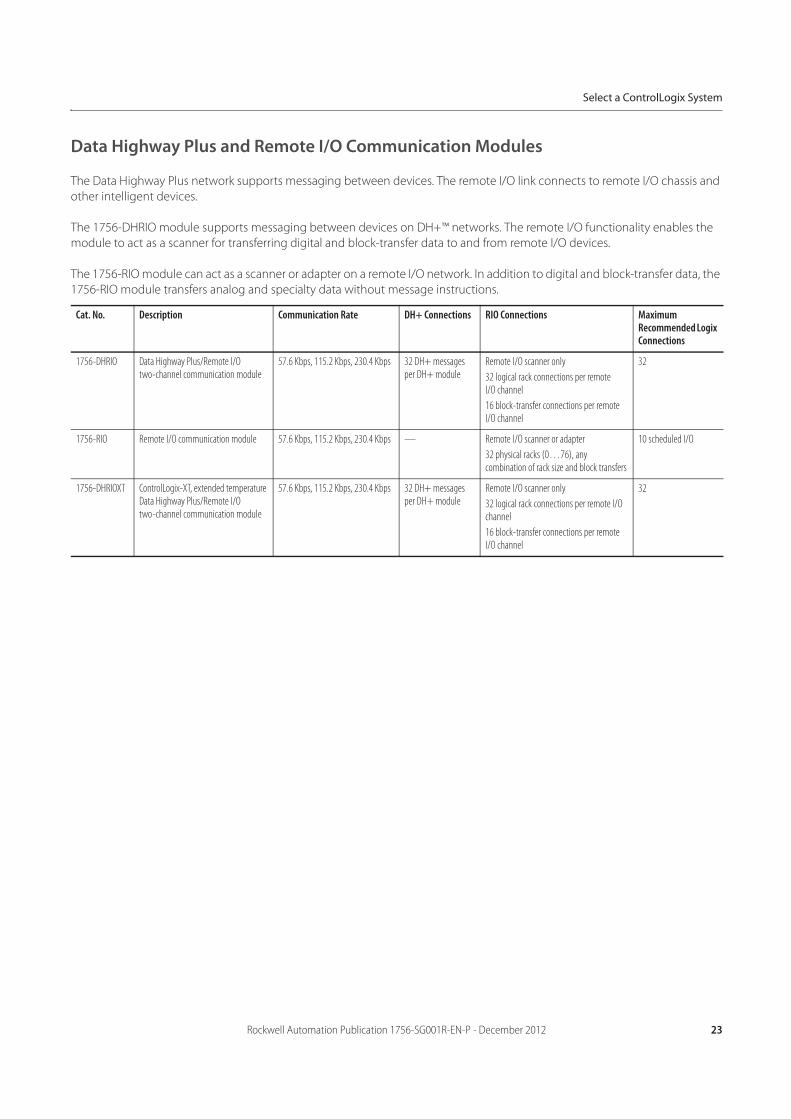
Data Highway Plus and Remote I/O Communication Modules
The Data Highway Plus network supports messaging between devices. The remote I/O link connects to remote I/O chassis and
other intelligent devices.
The 1756-DHRIO module supports messaging between devices on DH+™ networks. The remote I/O functionality enables the
module to act as a scanner for transferring digital and block-transfer data to and from remote I/O devices.
The 1756-RIO module can act as a scanner or adapter on a remote I/O network. In addition to digital and block-transfer data, the
1756-RIO module transfers analog and specialty data without message instructions.
Cat. No. Description Communication Rate DH+ Connections RIO Connections Maximum Recommended Logix Connections
1756-DHRIO Data Highway Plus/Remote I/O two-channel communication module
57.6 Kbps, 115.2 Kbps, 230.4 Kbps 32 DH+ messages per DH+ module
Remote I/O scanner only
32 logical rack connections per remote I/O channel
16 block-transfer connections per remote I/O channel
32
1756-RIO Remote I/O communication module 57.6 Kbps, 115.2 Kbps, 230.4 Kbps — Remote I/O scanner or adapter
32 physical racks (0…76), any combination of rack size and block transfers
10 scheduled I/O
1756-DHRIOXT ControlLogix-XT, extended temperature Data Highway Plus/Remote I/O two-channel communication module
57.6 Kbps, 115.2 Kbps, 230.4 Kbps 32 DH+ messages per DH+ module
Remote I/O scanner only
32 logical rack connections per remote I/O channel
16 block-transfer connections per remote I/O channel
32
24 Rockwell Automation Publication 1756-SG001R-EN-P - December 2012
Select a ControlLogix System
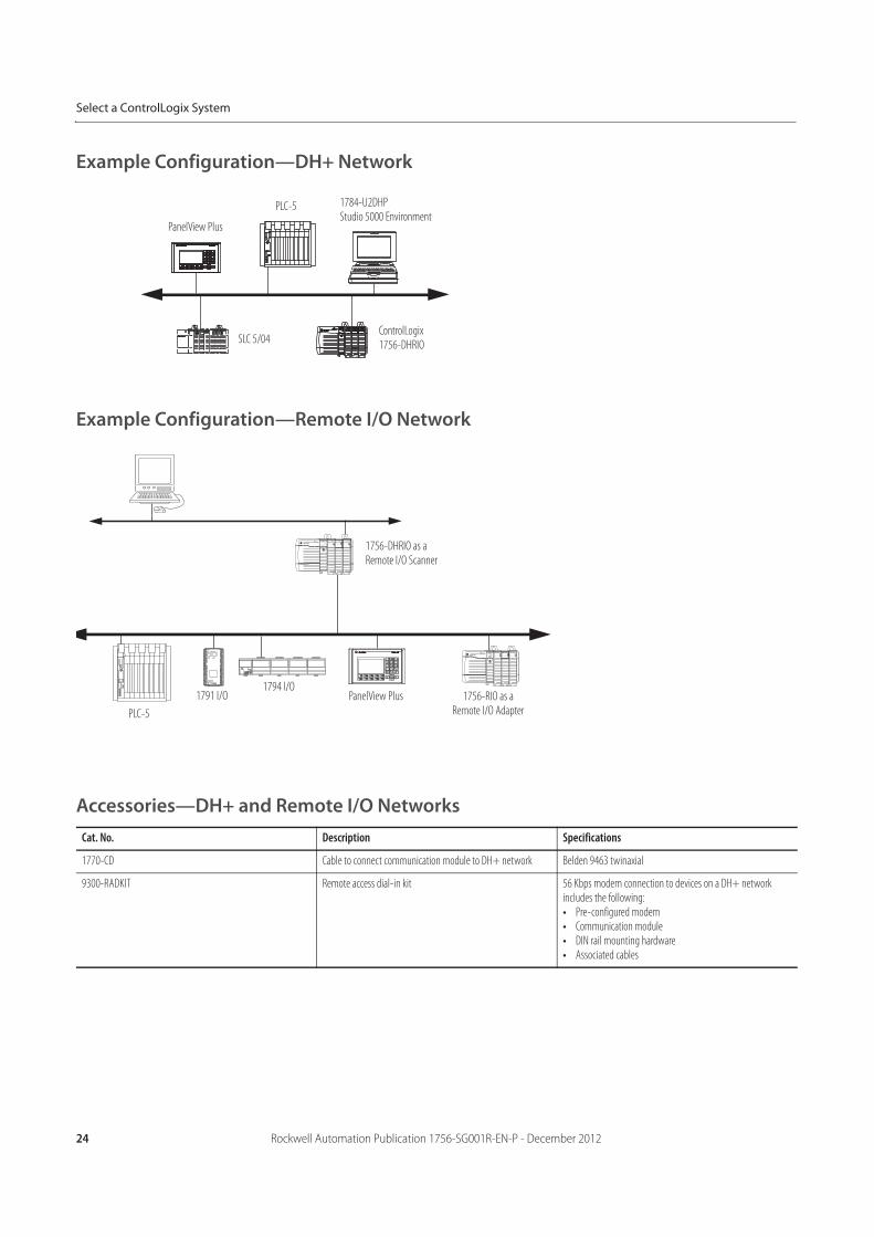
Example Configuration—DH+ Network
Example Configuration—Remote I/O Network
Accessories—DH+ and Remote I/O Networks
Cat. No. Description Specifications
1770-CD Cable to connect communication module to DH+ network Belden 9463 twinaxial
9300-RADKIT Remote access dial-in kit 56 Kbps modem connection to devices on a DH+ network includes the following:• Pre-configured modem• Communication module• DIN rail mounting hardware• Associated cables
PanelView Plus
PLC-5 1784-U2DHPStudio 5000 Environment
ControlLogix1756-DHRIO
SLC 5/04
PanelView Plus
PLC-5
1791 I/O1794 I/O
1756-RIO as a Remote I/O Adapter
1756-DHRIO as a Remote I/O Scanner
Rockwell Automation Publication 1756-SG001R-EN-P - December 2012 25
Select a ControlLogix System
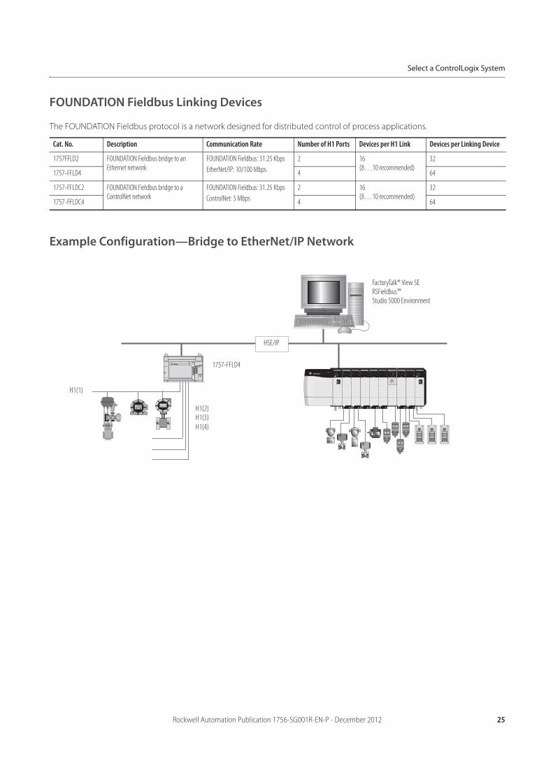
FOUNDATION Fieldbus Linking Devices
The FOUNDATION Fieldbus protocol is a network designed for distributed control of process applications.
Example Configuration—Bridge to EtherNet/IP Network
Cat. No. Description Communication Rate Number of H1 Ports Devices per H1 Link Devices per Linking Device
1757FFLD2 FOUNDATION Fieldbus bridge to an Ethernet network
FOUNDATION Fieldbus: 31.25 Kbps
EtherNet/IP: 10/100 Mbps
2 16(8…10 recommended)
32
1757-FFLD4 4 64
1757-FFLDC2 FOUNDATION Fieldbus bridge to a ControlNet network
FOUNDATION Fieldbus: 31.25 Kbps
ControlNet: 5 Mbps
2 16(8…10 recommended)
32
1757-FFLDC4 4 64
FactoryTalk® View SERSFieldbus™Studio 5000 Environment
1757-FFLD4
H1(1)
H1(2)H1(3)
H1(4)
HSE/IP
26 Rockwell Automation Publication 1756-SG001R-EN-P - December 2012
Select a ControlLogix System
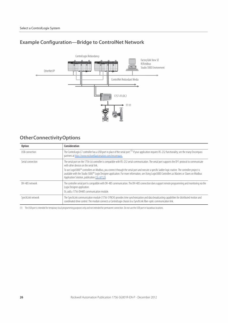
Example Configuration—Bridge to ControlNet Network
Other Connectivity Options
Option Consideration
USB connection The ControlLogix L7 controller has a USB port in place of the serial port.(1) If your application requires RS-232 functionality, see the many Encompass partners at http://www.rockwellautomation.com/encompass.
(1) The USB port is intended for temporary local programming purposes only and not intended for permanent connection. Do not use the USB port in hazardous locations.
Serial connection The serial port on the 1756-L6 controller is compatible with RS-232 serial communication. The serial port supports the DF1 protocol to communicate with other devices on the serial link.
To use Logix5000™ controllers on Modbus, you connect through the serial port and execute a specific ladder logic routine. The controller project is available with the Studio 5000™ Logix Designer application. For more information, see Using Logix5000 Controllers as Masters or Slaves on Modbus Application Solution, publication CIG-AP129.
DH-485 network The controller serial port is compatible with DH-485 communication. The DH-485 connection does support remote programming and monitoring via the Logix Designer application.
Or, add a 1756-DH485 communication module.
SynchLink network The SynchLink communication module (1756-SYNCH) provides time synchronization and data broadcasting capabilities for distributed motion and coordinated drive control. The module connects a ControlLogix chassis to a SynchLink fiber-optic communication link.
ControlLogix Redundancy
FactoryTalk View SERSFieldbusStudio 5000 Environment
ControlNet Redundant Media
1757-FFLDC2
FF H1
EtherNet/IP
Rockwell Automation Publication 1756-SG001R-EN-P - December 2012 27
Select a ControlLogix System
ControlLogix Controllers
The ControlLogix controller provides a scalable controller solution that is capable of addressing a large amount of I/O points.
The controller can be placed into any slot of a ControlLogix chassis and multiple controllers can be installed in the same chassis.
Multiple controllers in the same chassis communicate with each other over the backplane (just as controllers can communicate
over networks) but operate independently.
ControlLogix controllers can monitor and control I/O across the ControlLogix backplane, as well as over I/O links. ControlLogix
controllers can communicate over EtherNet/IP, ControlNet, DeviceNet, DH+, Remote I/O, and RS-232-C (DF1/DH-485 protocol)
networks and many third party process and device networks. To provide communication for a ControlLogix controller, install
the appropriate communication interface module into the chassis.
For detailed specifications, see the 1756 ControlLogix Controllers Specifications Technical Data, publication 1756-TD001.
Cat. No. Description User Memory
1756-L71 ControlLogix controller, 1 built-in USB port(1)
(1) The USB port is intended for temporary local programming purposes only and not intended for permanent connection. Do not use the USB port in hazardous locations.
2 MB
1756-L72 4 MB
1756-L73 8 MB
1756-L74 16 MB
1756-L75 32 MB
1756-L61 ControlLogix controller, 1 built-in RS-232 port 2 MB
1756-L62 4 MB
1756-L63 8 MB
1756-L64* *Important: Scan time for a project loaded in a 1756-L64 or 1756-L65 controller may be slower than for the same project loaded in one of the other 1756-L6 controllers. See the Logix5000 Controllers Instruction Execution Time and Memory Use Reference Manual, publication 1756-RM087, for instruction execution times.
16 MB
1756-L65* 32 MB
1756-L63XT ControlLogix-XT controller, extreme environment 8 MB
1756-L73XT 8 MB
1756-L61S GuardLogix safety controller 2 MB standard1 MB safety
1756-L62S 4 MB standard1 MB safety
1756-L63S 8 MB standard3.75 MB safety
1756-L71S 2 MB standard1 MB safety
1756-L72S 4 MB standard2 MB safety
1756-L73S 8 MB standard4 MB safety
1756-LSP GuardLogix safety partner (one is required for each GuardLogix L6 controller) —
1756-L7SP GuardLogix safety partner (one is required for each GuardLogix L7 controller) —
28 Rockwell Automation Publication 1756-SG001R-EN-P - December 2012
Select a ControlLogix System
Standard ControlLogix Controllers
The ControlLogix controller is part of the Logix5000 family of controllers. A ControlLogix system
includes the following:
• The ControlLogix controller, available in different combinations of user memory• Studio 5000 environment• 1756 ControlLogix I/O modules that reside in a 1756 chassis• Separate communication modules for network communication
Feature 1756-L61, 1756-L62, 1756-L63, 1756-L64, 1756-L65 1756-L71, 1756-L72, 1756-L73, 1756-L74, 1756-L75
Controller tasks • 32 tasks• 100 programs/task• Event tasks: all event triggers
Built-in communication ports 1 port RS-232 serial 1 port USB
Communication options • EtherNet/IP• ControlNet• DeviceNet• Data Highway Plus• Remote I/O• SynchLink• Third-party process and device networks
Built-in port Serial USB
Controller connections supported, max 250 500
Network connections, per network module • 256 EtherNet/IP; 128 TCP (1756-EN2x, 1756-EN3x)• 128 EtherNet/IP; 64 TCP (1756-ENBT)• 128 ControlNet (1756-CN2/B, 1756-CN2R/B)• 64 DeviceNet (1756-DNB)
Controller redundancy Full support
Integrated motion • EtherNet/IP connection• SERCOS interface• Analog options (encoder input, LDT input, SSI input)
Programming languages • Relay ladder• Structured text• Function block• Sequential function chart (SFC)
Rockwell Automation Publication 1756-SG001R-EN-P - December 2012 29
Select a ControlLogix System
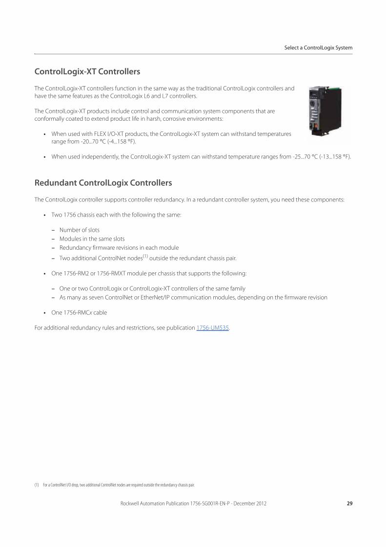
ControlLogix-XT Controllers
The ControlLogix-XT controllers function in the same way as the traditional ControlLogix controllers and
have the same features as the ControlLogix L6 and L7 controllers.
The ControlLogix-XT products include control and communication system components that are
conformally coated to extend product life in harsh, corrosive environments:
• When used with FLEX I/O-XT products, the ControlLogix-XT system can withstand temperatures
range from -20...70 °C (-4...158 °F).
• When used independently, the ControlLogix-XT system can withstand temperature ranges from -25...70 °C (-13...158 °F).
Redundant ControlLogix Controllers
The ControlLogix controller supports controller redundancy. In a redundant controller system, you need these components:
• Two 1756 chassis each with the following the same:
– Number of slots
– Modules in the same slots
– Redundancy firmware revisions in each module
– Two additional ControlNet nodes(1) outside the redundant chassis pair.
• One 1756-RM2 or 1756-RMXT module per chassis that supports the following:
– One or two ControlLogix or ControlLogix-XT controllers of the same family
– As many as seven ControlNet or EtherNet/IP communication modules, depending on the firmware revision
• One 1756-RMCx cable
For additional redundancy rules and restrictions, see publication 1756-UM535.
(1) For a ControlNet I/O drop, two additional ControlNet nodes are required outside the redundancy chassis pair.
30 Rockwell Automation Publication 1756-SG001R-EN-P - December 2012
Select a ControlLogix System
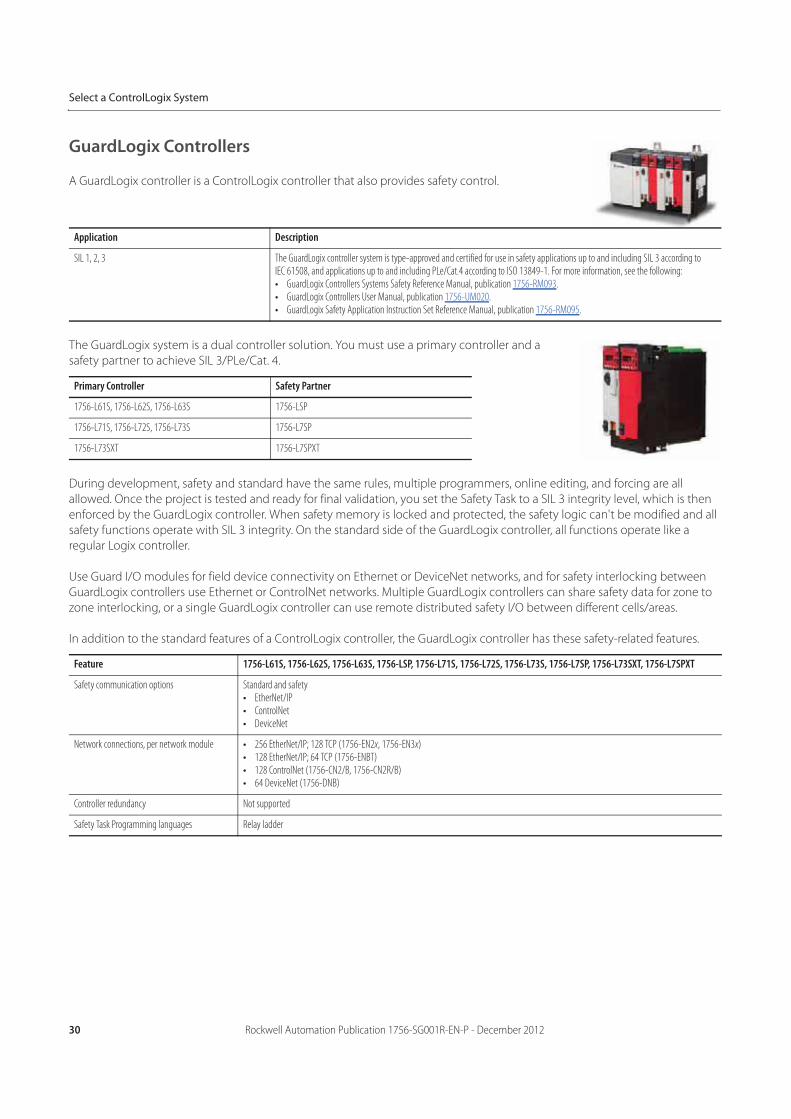
GuardLogix Controllers
A GuardLogix controller is a ControlLogix controller that also provides safety control.
The GuardLogix system is a dual controller solution. You must use a primary controller and a
safety partner to achieve SIL 3/PLe/Cat. 4.
During development, safety and standard have the same rules, multiple programmers, online editing, and forcing are all
allowed. Once the project is tested and ready for final validation, you set the Safety Task to a SIL 3 integrity level, which is then
enforced by the GuardLogix controller. When safety memory is locked and protected, the safety logic can't be modified and all
safety functions operate with SIL 3 integrity. On the standard side of the GuardLogix controller, all functions operate like a
regular Logix controller.
Use Guard I/O modules for field device connectivity on Ethernet or DeviceNet networks, and for safety interlocking between
GuardLogix controllers use Ethernet or ControlNet networks. Multiple GuardLogix controllers can share safety data for zone to
zone interlocking, or a single GuardLogix controller can use remote distributed safety I/O between different cells/areas.
In addition to the standard features of a ControlLogix controller, the GuardLogix controller has these safety-related features.
Application Description
SIL 1, 2, 3 The GuardLogix controller system is type-approved and certified for use in safety applications up to and including SIL 3 according to IEC 61508, and applications up to and including PLe/Cat.4 according to ISO 13849-1. For more information, see the following:• GuardLogix Controllers Systems Safety Reference Manual, publication 1756-RM093.• GuardLogix Controllers User Manual, publication 1756-UM020.• GuardLogix Safety Application Instruction Set Reference Manual, publication 1756-RM095.
Primary Controller Safety Partner
1756-L61S, 1756-L62S, 1756-L63S 1756-LSP
1756-L71S, 1756-L72S, 1756-L73S 1756-L7SP
1756-L73SXT 1756-L7SPXT
Feature 1756-L61S, 1756-L62S, 1756-L63S, 1756-LSP, 1756-L71S, 1756-L72S, 1756-L73S, 1756-L7SP, 1756-L73SXT, 1756-L7SPXT
Safety communication options Standard and safety• EtherNet/IP• ControlNet• DeviceNet
Network connections, per network module • 256 EtherNet/IP; 128 TCP (1756-EN2x, 1756-EN3x)• 128 EtherNet/IP; 64 TCP (1756-ENBT)• 128 ControlNet (1756-CN2/B, 1756-CN2R/B)• 64 DeviceNet (1756-DNB)
Controller redundancy Not supported
Safety Task Programming languages Relay ladder
Rockwell Automation Publication 1756-SG001R-EN-P - December 2012 31
Select a ControlLogix System
Accessories—Controllers
Memory Cards
Memory cards offer nonvolatile memory to permanently store a user program and tag data on a controller. The ControlLogix L7
and GuardLogix L7 controllers ship with 1784-SD1 Secure Digital (SD) card already installed. The ControlLogix L6 and
GuardLogix L6 controllers support optional CompactFlash cards that you purchase separately. The memory card installs in a
socket on the controller. Through the Logix Designer application, you can manually trigger the controller to save to or load from
nonvolatile memory or configure the controller to load from nonvolatile memory on powerup.
1756 Energy Storage Modules
Instead of a battery, the ControlLogix L7 and GuardLogix L7 controllers ship with a 1756-ESMCAP energy storage module (ESM)
already installed.
The ControlLogix-XT L7 extreme temperature controller ships with a 1756-ESMNCAPXT energy storage module installed.
The 1756-L7SP safety partner for a GuardLogix system has the following modules available.
Attribute 1784-CF128 1784-SD1 1784-SD2
Memory 128 MB 1 GB 2 GB
Supported controllers 1756 ControlLogix L6 and 1756 GuardLogix L6 1756 ControlLogix L7 and 1756 GuardLogix L7
Weight, approx. 14.2 g (0.5 oz) 1.76 g (0.062 oz)
Cat No. Description
1756-ESMCAP Capacitor-based ESM included with the controller.
1756-ESMNSE ESM without WallClockTime back-up power. Additionally, you can use this ESM with a 1756-L73 (8 MB) or smaller memory-sized controller only.
Use this ESM if your application requires that the installed ESM deplete its residual energy to 40 μJ or less before transporting it into or out of your application.
1756-ESMNRM ESM that secures the controller by permanently preventing the USB connection and SD card use.
This ESM provides your application an enhanced degree of security.
Cat No. Description
1756-ESMCAPXT Capacitor-based ESM included with the controller.
1756-ESMNSEXT ESM without WallClockTime back-up power. Additionally, you can use this ESM with a1756-L73XT (8 MB) or smaller memory-sized controller only.
Use this ESM if your application requires that the installed ESM deplete its residual energy to 40 μJ or less before transporting it into or out of your application.
1756-ESMNRMXT ESM that secures the controller by permanently preventing the USB connection and SD card use.
This ESM provides your application an enhanced degree of security.
Cat No. Description
1756-SPESMNSE Capacitor-based ESM for a GuardLogix safety partner.
1756-SPESMNRM ESM for a GuardLogix safety partner that secures the safety partner by permanently preventing the USB connection and SD card use.
32 Rockwell Automation Publication 1756-SG001R-EN-P - December 2012
Select a ControlLogix System
1756 ControlLogix Batteries
Each ControlLogix 1756-L6 and GuardLogix 1756-L6 controller ships with a battery. With a memory card installed, the controller
can be used without a battery. If you do not use a battery, current tag data will be at the state it was when the memory card was
saved.
ControlLogix Chassis
The ControlLogix system is a modular system that requires a 1756 I/O chassis. Place
any module into any slot. The backplane provides a high-speed communication path
between modules.
All of the chassis are designed for horizontal-only, back-panel mounting. The chassis
are available in these configurations:
• Standard chassis
• ControlLogix-XT chassis
For detailed specifications, see the 1756 ControlLogix Chassis Specifications Technical Data, publication 1756-TD006.
Standard Chassis
The chassis backplane provides a high-speed communication path between modules and distributes power to each of the
modules within the chassis.
Attribute 1756-BA1 1756-BA2 1756-BATM(1)
(1) The 1756-BATM externally mounted battery assembly is highly recommended for use with all series A, 1756 ControlLogix L6 controllers and provides longer battery life than the 1756-BA1 battery.
The 1756-BATM includes one 1756-BATA lithium battery assembly and a 1 m (3.28 ft) cable to connect housing to controller.
1756-BATA
Description Lithium battery (0.59 g) Lithium battery (0.59 g) Externally mounted battery assembly Replacement lithium battery for 1756-BATM (5 g max lithium per each D cell; contains 2 D cells)
ControlLogix controllers 1756-L61/A, 1756-L62/A, 1756-L63/A
1756-L61/B, 1756-L62/B, 1756-L63/B
1756-L64/B, 1756-L65/B
1756-L61/A, 1756-L62/A, 1756-L63/A
—
GuardLogix controllers — 1756-L61S, 1756-L62S, 1756-L63S — —
ControlLogix-XT controllers — 1756-L63XT — —
Cat. No. Description Slots
1756-A4 Standard chassis 4
1756-A7 7
1756-A10 10
1756-A13 13
1756-A17 17
Rockwell Automation Publication 1756-SG001R-EN-P - December 2012 33
Select a ControlLogix System
ControlLogix-XT Chassis
The ControlLogix-XT chassis support extreme temperature environments.
Accessories - Chassis
Use a slot filler module to fill empty slots.
ControlLogix Power Supplies
ControlLogix power supplies are used with the 1756 chassis to provide 1.2V, 3.3V, 5V, and 24V DC
power directly to the chassis backplane. Select from these configurations:
• Standard power supplies
• ControlLogix-XT power supplies
• Redundant power supplies
For detailed specifications, see the 1756 ControlLogix Power Supplies Specifications Technical Data,
publication 1756-TD005.
Standard Power Supplies
You mount a standard power supply directly on the left end of the chassis, where it plugs directly into the backplane.
Cat. No. Description Slots Temperature Range
1756-A4LXT ControlLogix-XT chassis 4 -25…60 °C (-13…140 °F)
1756-A5XT 5 -25…70 °C (-13…158 °F)
1756-A7XT 7 -25…70 °C (-13…158 °F)
1756-A7LXT 7 -25…60 °C (-13…140 °F)
Cat. No. Description
1756-N2 Slot filler module for empty slots in standard ControlLogix chassis
1756-N2XT Slot filler module for empty slots in ControlLogix-XT chassis
Cat. No. Description Voltage Category Operating Voltage Range Chassis
1756-PA72 Standard AC power supply 120V/220V AC 85…265V AC Standard, series A and series B
1756-PA75 120V/220V AC 85…265V AC Standard, series B
1756-PB72 Standard DC power supply 24V DC 18…32V DC Standard, series A and series B
1756-PB75 24V DC 18…32V DC Standard, series B
1756-PC75 48V DC 30…60V DC Standard, series B
1756-PH75 125V DC 90…143V DC Standard, series B
34 Rockwell Automation Publication 1756-SG001R-EN-P - December 2012
Select a ControlLogix System
ControlLogix-XT Power Supplies
The ControlLogix-XT power supplies support extreme temperature environments.
Redundant Power Supplies
A redundant power supply system provides additional uptime protection for chassis used in critical applications. The redundant
power supplies funnel power through the chassis adapter module to the ControlLogix Series B chassis backplane. To build a
redundant power supply system you need the following components.
Visualization Products
Visualization products, together with Logix for control and NetLinx architecture for communication, make up the
Rockwell Automation Integrated Architecture™ strategy. The visualization strategy combines Rockwell Automation expertise in
Allen-Bradley® electronic operator interface and industrialized personal computer hardware with Rockwell Software®
supervisory control software. Current visualization products include the following:
• FactoryTalk View software
• PanelView Plus operator interface
• PanelView Plus CE operator interface
• Industrial computers and monitors
For more information, see the Operator Interface catalog pages at http://www.ab.com/en/epub/catalogs/12762/2181376/
1239781/.
Cat. No. Description Voltage Category Operating Voltage Range Chassis
1756-PAXT ControlLogix-XT AC power supply 85…265V AC 120/240V AC XT
1756-PBXT ControlLogix-XT DC power supply 24V DC 18…32V DC XT
Cat. No. Amount Description Voltage Category Operating Voltage Range Chassis
1756-PAR2 Kit Bundled system contains:– Two1756-PA75R power supplies– Two 1756-CPR2 cables– One 1756-PSCA2 chassis adapter module
110V AC N/A Standard, series B
1756-PBR2 Kit Bundled system contains:– Two 1756-PB75R power supples– Two 1756-CPR2 cables– One 1756-PSCA2 chassis adapter module
24V DC N/A
1756-PA75R/A
or
1756-PB75R/A
2 Redundant AC power supply
Redundant DC power supply
120V/220V AC
24V DC
85…256V AC
19.2…32V DC
1756-CPR2 2 Redundant power supply cable (Length = 0.91 m [3 ft])
N/A N/A
1756-PSCA2 1 Redundant power supply chassis adapter module
N/A (user-supplied) 2 Annunciator wiring(1) (Maximum length = 10 m [32.8 ft])
(1) Optional user-supplied annunciator wiring can be connected to the solid state relay for status and troubleshooting purposes.
Rockwell Automation Publication 1756-SG001R-EN-P - December 2012 35
Select a ControlLogix System
Programming Software
Your selection of modules and network configuration determines what software packages you need to configure and program
your system.
Studio 5000 Environment
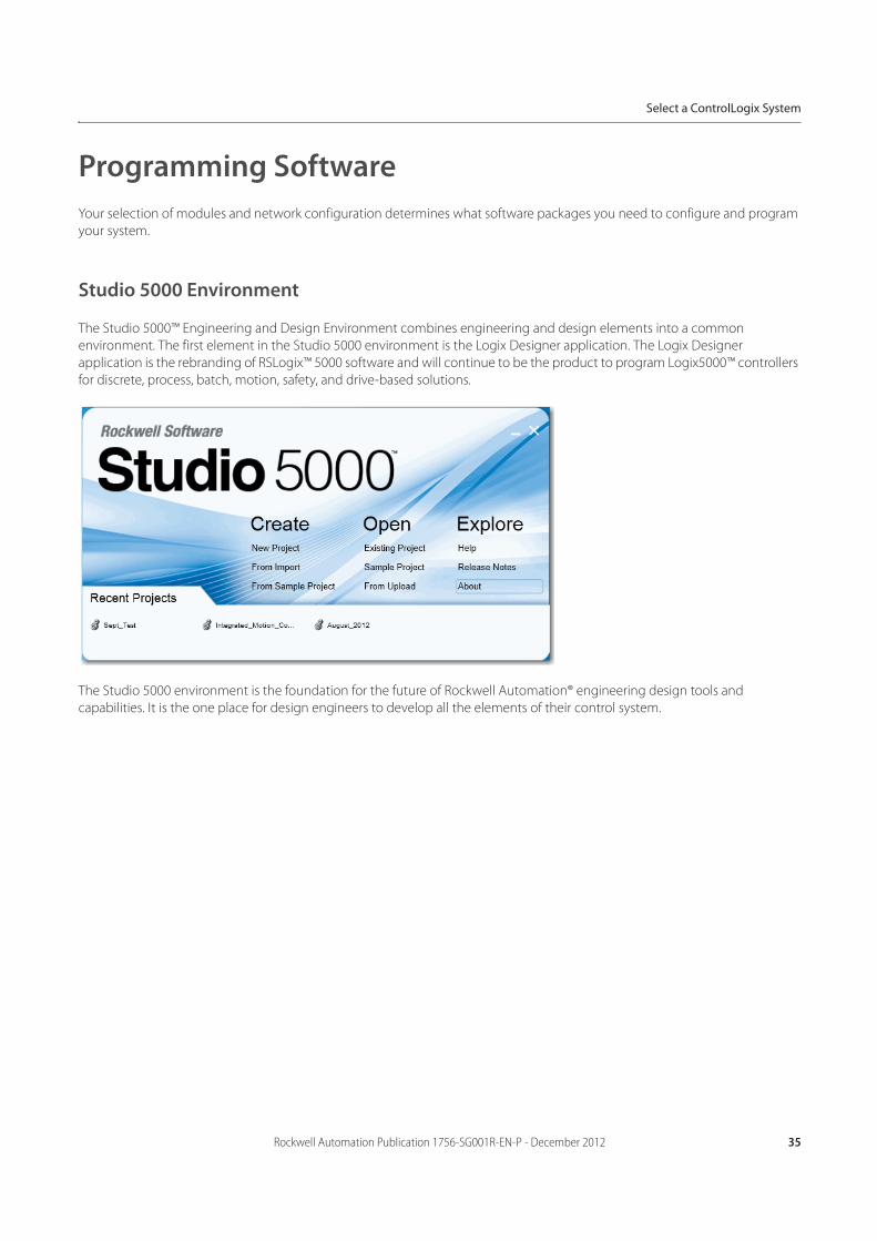
The Studio 5000™ Engineering and Design Environment combines engineering and design elements into a common
environment. The first element in the Studio 5000 environment is the Logix Designer application. The Logix Designer
application is the rebranding of RSLogix™ 5000 software and will continue to be the product to program Logix5000™ controllers
for discrete, process, batch, motion, safety, and drive-based solutions.
The Studio 5000 environment is the foundation for the future of Rockwell Automation® engineering design tools and
capabilities. It is the one place for design engineers to develop all the elements of their control system.
36 Rockwell Automation Publication 1756-SG001R-EN-P - December 2012
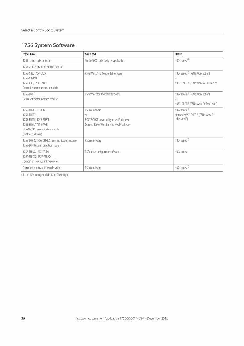
Select a ControlLogix System
1756 System Software
If you have You need Order
1756 ControlLogix controller Studio 5000 Logix Designer application 9324 series (1)
(1) All 9324 packages include RSLinx Classic Light.
1756 SERCOS or analog motion module
1756-CN2, 1756-CN2R
1756-CN2RXT
1756-CNB, 1756-CNBR
ControlNet communication module
RSNetWorx™ for ControlNet software 9324 series(1) (RSNetWorx option)
or
9357-CNETL3 (RSNetWorx for ControlNet)
1756-DNB
DeviceNet communication module
RSNetWorx for DeviceNet software 9324 series(1) (RSNetWorx option)
or
9357-DNETL3 (RSNetWorx for DeviceNet)
1756-EN2F, 1756-EN2T
1756-EN2TX
1756-EN2TR, 1756-EN3TR
1756-ENBT, 1756-EWEB
EtherNet/IP communication module
(set the IP address)
RSLinx software
or
BOOTP/DHCP server utility to set IP addresses
Optional RSNetWorx for EtherNet/IP software
9324 series(1)
Optional 9357-ENETL3 (RSNetWorx for EtherNet/IP)
1756-DHRIO, 1756-DHRIOXT communication module
1756-DH485 communication module
RSLinx software 9324 series(1)
1757-FFLD2, 1757-FFLD4
1757-FFLDC2, 1757-FFLDC4
Foundation Fieldbus linking device
RSFieldbus configuration software 9308 series
Communication card in a workstation RSLinx software 9324 series(1)

Rockwell Automation Publication 1756-SG001R-EN-P - December 2012 37
Select a ControlLogix System
Studio 5000 Logix Designer Application
To use the Logix Designer application effectively, your personal computer must meet the following hardware and software
requirements for the Studio 5000 environment, version 21.00.00.
Hardware Requirements
The personal computer must meet these minimum requirements. Using a computer meeting or exceeding the recommended
characteristics will improve performance.
Software Requirements
Operating system and service pack compatibility is as follows:
• This version of Logix Designer has been tested on the following operating systems:
– Microsoft Windows 7 Professional (64-bit) with Service Pack 1
– Microsoft Windows 7 Home Premium (64-bit) with Service Pack 1
– Microsoft Windows 7 Home Premium (32-bit) with Service Pack 1
– Microsoft Windows Server 2008 R2 Standard Edition with Service Pack 1
• This version of the Logix Designer application has not been tested but is expected to operate correctly on all other
editions and service packs of the following operating systems:
– Microsoft Windows 7
– Microsoft Windows Server 2008 R2
• For operating systems that support User Account Control (UAC), this version of the Logix Designer application was tested
with UAC set to the most restrictive level ("Always notify" for Windows 7). This version of the Logix Designer application is
also expected to operate correctly when UAC is configured for any less restrictive setting.
• Running the Logix Designer application in conjunction with Fast-User Switching, in Safe mode, or via Remote Desktop is
not supported.
Characteristic Minimum Recommended
Processor Pentium 4 Intel Core i5
Speed 2.8 GHz 2.4 GHz
RAM memory 1 GB 8 GB
Hard disk space 16 GB free 20 GB free
Graphics device 1024x768, true color DirectX 9, with WDDM 1.0 or higher driver
38 Rockwell Automation Publication 1756-SG001R-EN-P - December 2012
Select a ControlLogix System
Additional Software Product Considerations
Additional software compatibility is as follows:
• FactoryTalk Services Platform, version 2.51 or later is not required to run the Logix Designer application; however, it is
required in order to perform some security functions in the Logix Designer application.
• RSLinx Classic communication software is not required to install the Logix Designer application; however, it is required in
order to perform online communication with controllers.
• RSLinx Classic version 3.51.00 is a component aligned to Logix Designer, version 21.00.00. RSLinx Classic, version 3.51.00
(CPR9 Service Release 5.1) has been tested, and is compatible, with the following products:
– FactoryTalk Services Platform, version 2.51.00
– RSLinx Enterprise, version 5.51.00
– RSNetWorx software, version 21.00.00
– FactoryTalk Activation Manager, version 3.51.00
• RSLinx Classic, version 3.51.00, Logix Designer application, version 21.00.00, and device profiles that ship with the
Logix Designer application, version 21.00.00 are not compatible with these products:
– RSNetWorx software, version 11.00.00 or earlier
– DeviceNet Tag Generator, version 11.0.20.0
RSNetWorx software and the DeviceNet Tag Generator must be upgraded prior to installing these products.
• FactoryTalk View SE (CPR 9) software and RSLinx Enterprise communication software are not required to install the
Logix Designer application; however, these products are required to fully use the alarm capabilities introduced with
version 16.03.00.
• Be sure to check the software requirements for other Rockwell Software products that you intend to install to be sure
that these products are also compatible with the system.


Publication 1756-SG001R-EN-P - December 2012Supersedes Publication 1756-SG001Q-EN-P - March 2012 Copyright © 2012 Rockwell Automation, Inc. All rights reserved. Printed in the U.S.A.
Allen-Bradley, Rockwell Automation, Rockwell Software, ArmorBlock, CompactBlock, CompactLogix, ControlLogix, ControlLogix-XT, Data Highway Plus, DH+, DriveExecutive, Encompass, FactoryTalk, FLEX Ex,
FLEX, FLEX I/O-XT, FlexLogix, Guard I/O, GuardLogix, Integrated Architecture, Kinetix, KwikLink, Logix5000, MicroLogix, PanelView, PLC-5, PhaseManager, POINT Guard I/O, POINT I/O, PowerFlex,
PowerMonitor, RSFieldbus, RSLinx, RSLogix, RSNetWorx, SLC, SoftLogix, Stratix 8000, SynchLink, StepForward, Ultra, 1336 Plus, and LISTEN.THINK.SOLVE. are trademarks of Rockwell Automation, Inc.
Trademarks not belonging to Rockwell Automation are property of their respective companies.