Embed Size (px)
Citation preview

1
Version #1218
American made leveling systems and landing gear.
Cylinders machined and assembled at our facility in Michigan.
Hydraulic jacks with lift capacities: 8k, 12k, 17k and 24k lbs. with the following stroke: 15”, 18”, 20” & 24”.
Custom cylinders available as well, larger lift capacity and longer stroke, custom brackets, etc.
Series wound marine grade pump & motors manufactured in Minnesota.
Durability from simplicity:
Individual power unit for each cylinder creates a smooth, reliable operation.
Bi-directional motor with a retract & extend solenoid, no cheap valves for each cylinder to fail.
Each pump only runs 25% of the time compared to a central pump that are responsible for 100% of the
load 100% of the time.
Controls for one touch automatic leveling, manual leveling & weatherproof switches with lockout.
Bigfoot Leveling Systems by Quadra Manufacturing
305 US 131 South, White Pigeon, MI 49099, call 800-752-9815, www.bigfootleveler.com
2
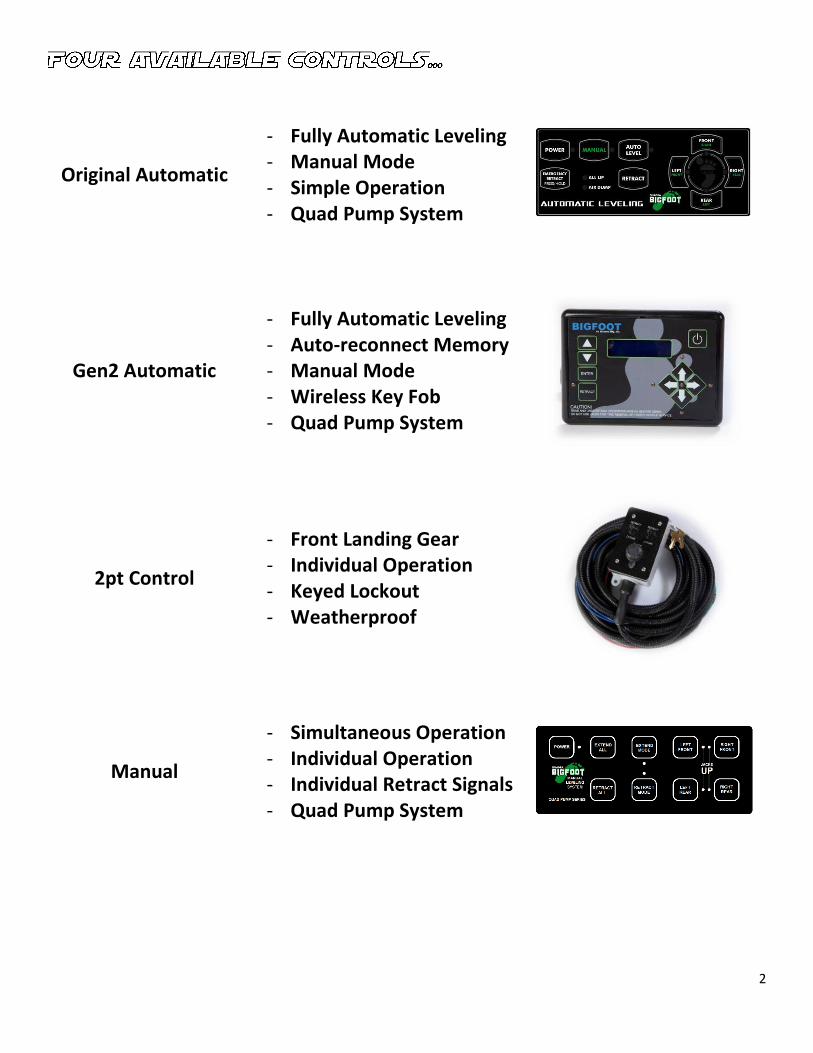
Original Automatic
- Fully Automatic Leveling - Manual Mode - Simple Operation - Quad Pump System
Gen2 Automatic
- Fully Automatic Leveling - Auto-reconnect Memory - Manual Mode - Wireless Key Fob - Quad Pump System
2pt Control
- Front Landing Gear - Individual Operation - Keyed Lockout - Weatherproof
Manual
- Simultaneous Operation - Individual Operation - Individual Retract Signals - Quad Pump System
3
Gen2: Operation Instructions
Set-up #1: Programming Your Sensor
1. Turn panel OFF, press FRONT 10 times, then press REAR 10 times.
2. Follow the instructions on the screen for selecting ONE sensor using the arrows on the
left side of the panel.
3. Place a carpenter’s level on the inside of your trailer (countertop, refrigerator or floor).
4. Manually operate by pressing FRONT, RIGHT, LEFT & REAR buttons to get the trailer level
from front to back and side to side.
5. Once level in both directions press ENTER. You’re done.
From this point forward when you press AUTO LEVEL your trailer or vehicle will return to this position.
Set-up #2: Programming your key fob to your control panel
1. Turn panel off
2. Press LEFT 5 times, then RIGHT 5 times
3. Press any button on key fob, PROGRAMMED.
The key fob has an automatic shut off after 10 seconds of no use,
to activate the fob simply press the BLUE button.
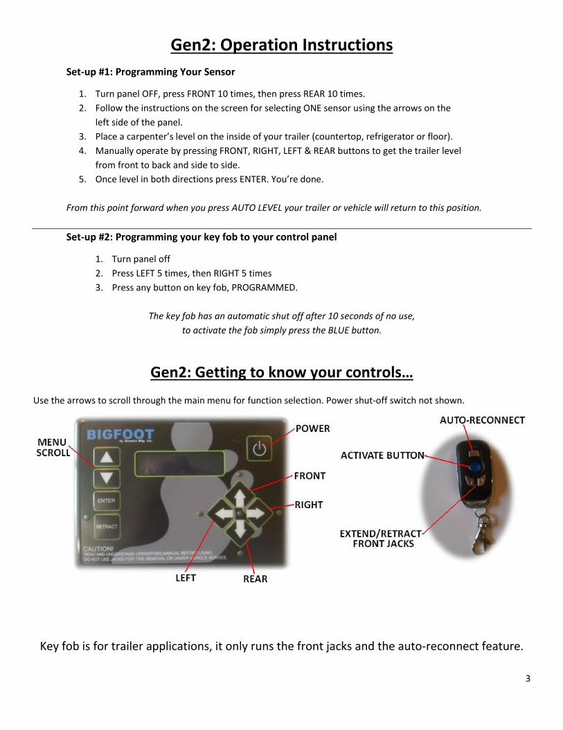
Gen2: Getting to know your controls…
Use the arrows to scroll through the main menu for function selection. Power shut-off switch not shown.
Key fob is for trailer applications, it only runs the front jacks and the auto-reconnect feature.
4
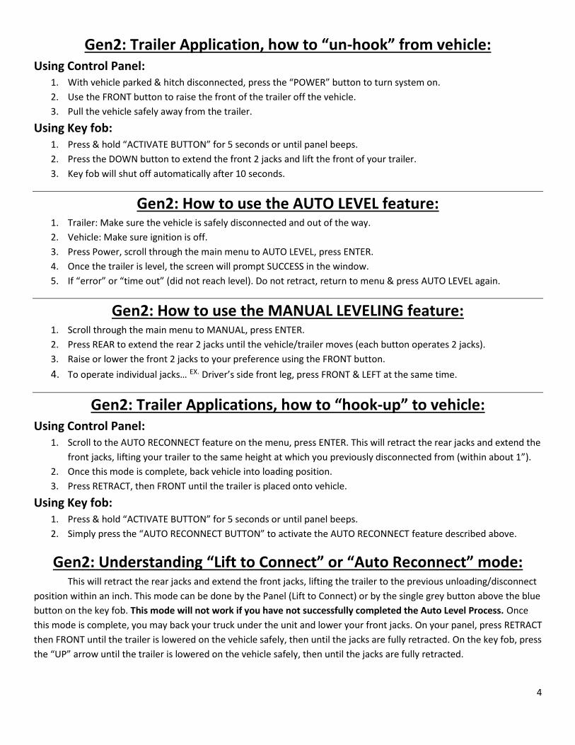
Gen2: Trailer Application, how to “un-hook” from vehicle: Using Control Panel:
1. With vehicle parked & hitch disconnected, press the “POWER” button to turn system on.
2. Use the FRONT button to raise the front of the trailer off the vehicle.
3. Pull the vehicle safely away from the trailer.
Using Key fob: 1. Press & hold “ACTIVATE BUTTON” for 5 seconds or until panel beeps.
2. Press the DOWN button to extend the front 2 jacks and lift the front of your trailer.
3. Key fob will shut off automatically after 10 seconds.
Gen2: How to use the AUTO LEVEL feature: 1. Trailer: Make sure the vehicle is safely disconnected and out of the way.
2. Vehicle: Make sure ignition is off.
3. Press Power, scroll through the main menu to AUTO LEVEL, press ENTER.
4. Once the trailer is level, the screen will prompt SUCCESS in the window.
5. If “error” or “time out” (did not reach level). Do not retract, return to menu & press AUTO LEVEL again.
Gen2: How to use the MANUAL LEVELING feature: 1. Scroll through the main menu to MANUAL, press ENTER.
2. Press REAR to extend the rear 2 jacks until the vehicle/trailer moves (each button operates 2 jacks).
3. Raise or lower the front 2 jacks to your preference using the FRONT button.
4. To operate individual jacks… EX. Driver’s side front leg, press FRONT & LEFT at the same time.
Gen2: Trailer Applications, how to “hook-up” to vehicle: Using Control Panel:
1. Scroll to the AUTO RECONNECT feature on the menu, press ENTER. This will retract the rear jacks and extend the
front jacks, lifting your trailer to the same height at which you previously disconnected from (within about 1”).
2. Once this mode is complete, back vehicle into loading position.
3. Press RETRACT, then FRONT until the trailer is placed onto vehicle.
Using Key fob: 1. Press & hold “ACTIVATE BUTTON” for 5 seconds or until panel beeps.
2. Simply press the “AUTO RECONNECT BUTTON” to activate the AUTO RECONNECT feature described above.
Gen2: Understanding “Lift to Connect” or “Auto Reconnect” mode: This will retract the rear jacks and extend the front jacks, lifting the trailer to the previous unloading/disconnect
position within an inch. This mode can be done by the Panel (Lift to Connect) or by the single grey button above the blue
button on the key fob. This mode will not work if you have not successfully completed the Auto Level Process. Once
this mode is complete, you may back your truck under the unit and lower your front jacks. On your panel, press RETRACT
then FRONT until the trailer is lowered on the vehicle safely, then until the jacks are fully retracted. On the key fob, press
the “UP” arrow until the trailer is lowered on the vehicle safely, then until the jacks are fully retracted.
5
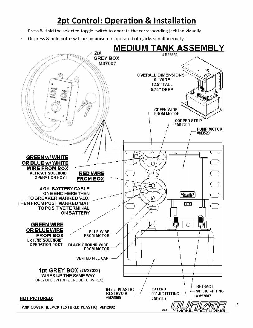
2pt Control: Operation & Installation - Press & Hold the selected toggle switch to operate the corresponding jack individually
- Or press & hold both switches in unison to operate both jacks simultaneously.
6
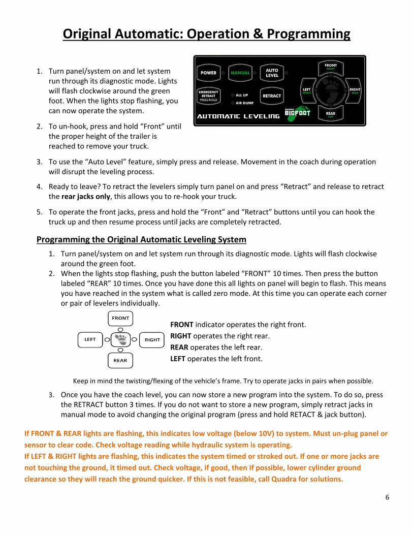
Original Automatic: Operation & Programming
1. Turn panel/system on and let system
run through its diagnostic mode. Lights will flash clockwise around the green foot. When the lights stop flashing, you can now operate the system.
2. To un-hook, press and hold “Front” until the proper height of the trailer is reached to remove your truck.
3. To use the “Auto Level” feature, simply press and release. Movement in the coach during operation will disrupt the leveling process.
4. Ready to leave? To retract the levelers simply turn panel on and press “Retract” and release to retract the rear jacks only, this allows you to re-hook your truck.
5. To operate the front jacks, press and hold the “Front” and “Retract” buttons until you can hook the truck up and then resume process until jacks are completely retracted.
Programming the Original Automatic Leveling System
1. Turn panel/system on and let system run through its diagnostic mode. Lights will flash clockwise around the green foot.
2. When the lights stop flashing, push the button labeled “FRONT” 10 times. Then press the button labeled “REAR” 10 times. Once you have done this all lights on panel will begin to flash. This means you have reached in the system what is called zero mode. At this time you can operate each corner or pair of levelers individually.
FRONT indicator operates the right front.
RIGHT operates the right rear.
REAR operates the left rear.
LEFT operates the left front.
Keep in mind the twisting/flexing of the vehicle’s frame. Try to operate jacks in pairs when possible.
3. Once you have the coach level, you can now store a new program into the system. To do so, press the RETRACT button 3 times. If you do not want to store a new program, simply retract jacks in manual mode to avoid changing the original program (press and hold RETACT & jack button).
If FRONT & REAR lights are flashing, this indicates low voltage (below 10V) to system. Must un-plug panel or
sensor to clear code. Check voltage reading while hydraulic system is operating.
If LEFT & RIGHT lights are flashing, this indicates the system timed or stroked out. If one or more jacks are
not touching the ground, it timed out. Check voltage, if good, then If possible, lower cylinder ground
clearance so they will reach the ground quicker. If this is not feasible, call Quadra for solutions.
7
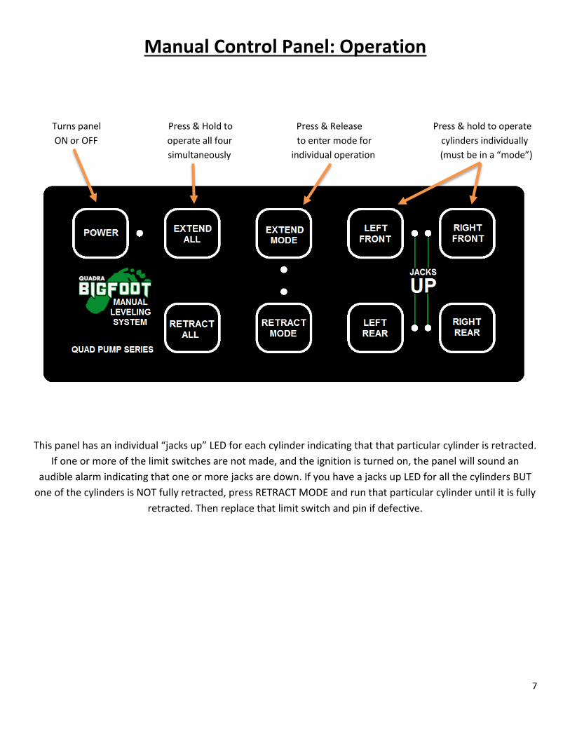
Manual Control Panel: Operation
Turns panel Press & Hold to Press & Release Press & hold to operate
ON or OFF operate all four to enter mode for cylinders individually
simultaneously individual operation (must be in a “mode”)
This panel has an individual “jacks up” LED for each cylinder indicating that that particular cylinder is retracted.
If one or more of the limit switches are not made, and the ignition is turned on, the panel will sound an
audible alarm indicating that one or more jacks are down. If you have a jacks up LED for all the cylinders BUT
one of the cylinders is NOT fully retracted, press RETRACT MODE and run that particular cylinder until it is fully
retracted. Then replace that limit switch and pin if defective.
8
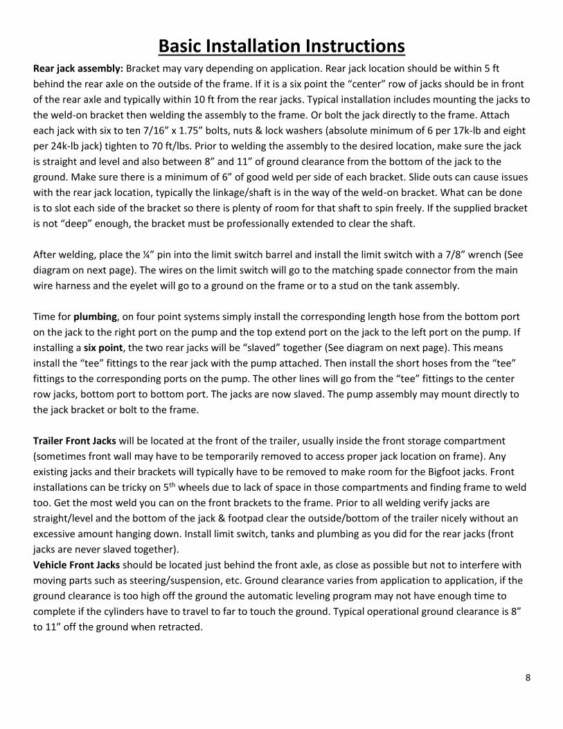
Basic Installation Instructions Rear jack assembly: Bracket may vary depending on application. Rear jack location should be within 5 ft
behind the rear axle on the outside of the frame. If it is a six point the “center” row of jacks should be in front
of the rear axle and typically within 10 ft from the rear jacks. Typical installation includes mounting the jacks to
the weld-on bracket then welding the assembly to the frame. Or bolt the jack directly to the frame. Attach
each jack with six to ten 7/16” x 1.75” bolts, nuts & lock washers (absolute minimum of 6 per 17k-lb and eight
per 24k-lb jack) tighten to 70 ft/lbs. Prior to welding the assembly to the desired location, make sure the jack
is straight and level and also between 8” and 11” of ground clearance from the bottom of the jack to the
ground. Make sure there is a minimum of 6” of good weld per side of each bracket. Slide outs can cause issues
with the rear jack location, typically the linkage/shaft is in the way of the weld-on bracket. What can be done
is to slot each side of the bracket so there is plenty of room for that shaft to spin freely. If the supplied bracket
is not “deep” enough, the bracket must be professionally extended to clear the shaft.
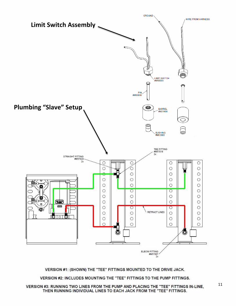
After welding, place the ¼” pin into the limit switch barrel and install the limit switch with a 7/8” wrench (See
diagram on next page). The wires on the limit switch will go to the matching spade connector from the main
wire harness and the eyelet will go to a ground on the frame or to a stud on the tank assembly.
Time for plumbing, on four point systems simply install the corresponding length hose from the bottom port
on the jack to the right port on the pump and the top extend port on the jack to the left port on the pump. If
installing a six point, the two rear jacks will be “slaved” together (See diagram on next page). This means
install the “tee” fittings to the rear jack with the pump attached. Then install the short hoses from the “tee”
fittings to the corresponding ports on the pump. The other lines will go from the “tee” fittings to the center
row jacks, bottom port to bottom port. The jacks are now slaved. The pump assembly may mount directly to
the jack bracket or bolt to the frame.
Trailer Front Jacks will be located at the front of the trailer, usually inside the front storage compartment
(sometimes front wall may have to be temporarily removed to access proper jack location on frame). Any
existing jacks and their brackets will typically have to be removed to make room for the Bigfoot jacks. Front
installations can be tricky on 5th wheels due to lack of space in those compartments and finding frame to weld
too. Get the most weld you can on the front brackets to the frame. Prior to all welding verify jacks are
straight/level and the bottom of the jack & footpad clear the outside/bottom of the trailer nicely without an
excessive amount hanging down. Install limit switch, tanks and plumbing as you did for the rear jacks (front
jacks are never slaved together).
Vehicle Front Jacks should be located just behind the front axle, as close as possible but not to interfere with
moving parts such as steering/suspension, etc. Ground clearance varies from application to application, if the
ground clearance is too high off the ground the automatic leveling program may not have enough time to
complete if the cylinders have to travel to far to touch the ground. Typical operational ground clearance is 8”
to 11” off the ground when retracted.
9
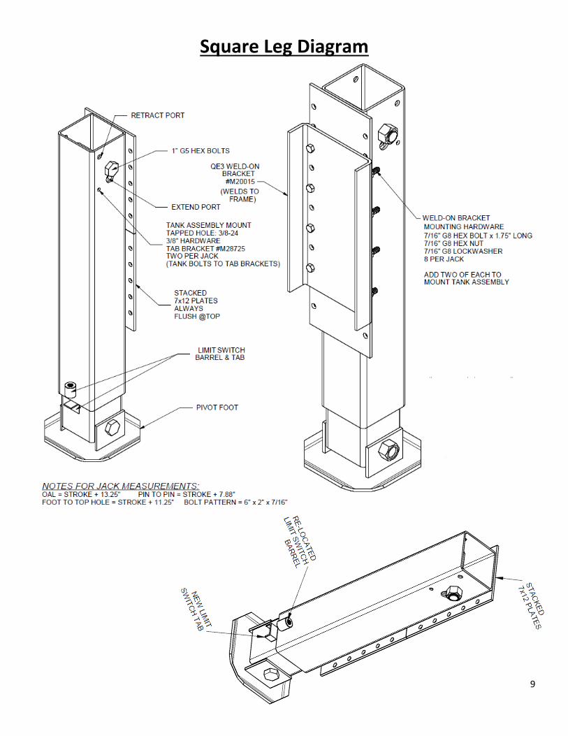
Square Leg Diagram
10
11
Limit Switch Assembly
Plumbing “Slave” Setup
12
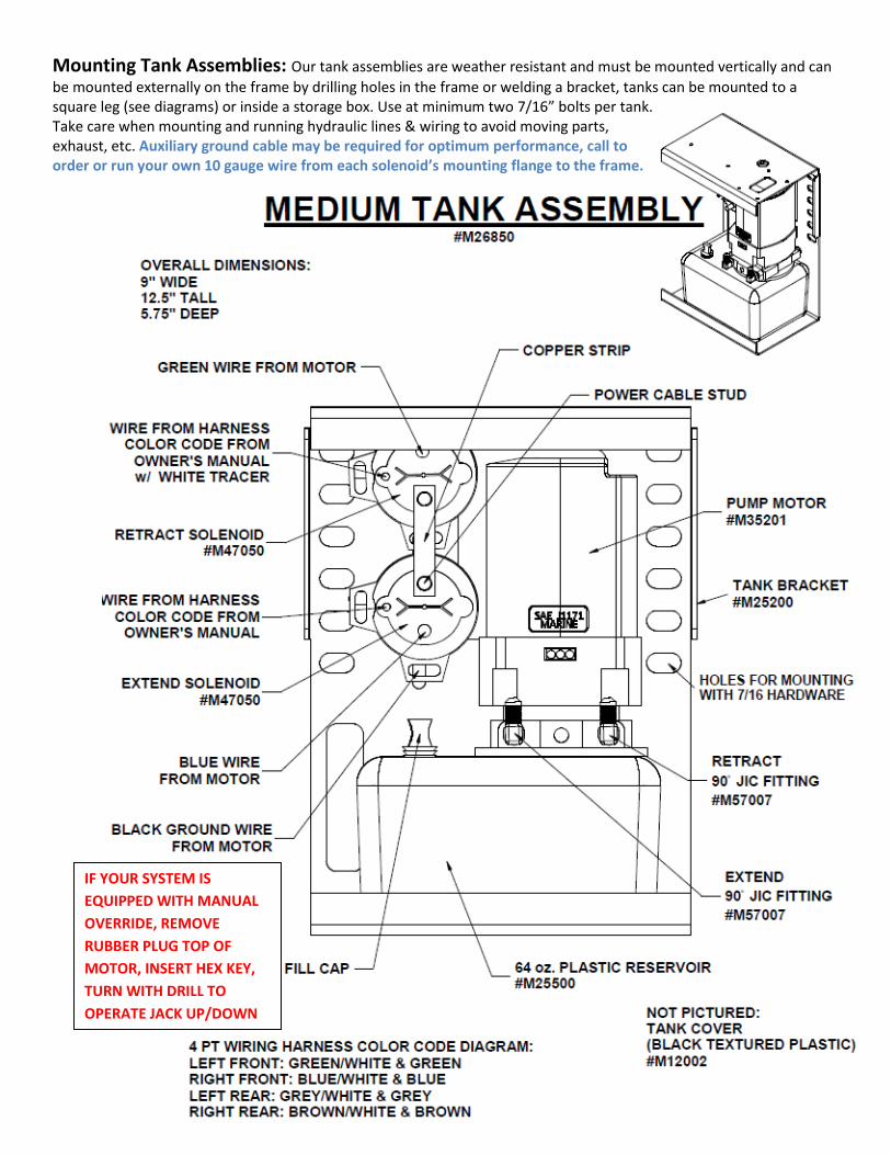
Mounting Tank Assemblies: Our tank assemblies are weather resistant and must be mounted vertically and can
be mounted externally on the frame by drilling holes in the frame or welding a bracket, tanks can be mounted to a square leg (see diagrams) or inside a storage box. Use at minimum two 7/16” bolts per tank. Take care when mounting and running hydraulic lines & wiring to avoid moving parts, exhaust, etc. Auxiliary ground cable may be required for optimum performance, call to order or run your own 10 gauge wire from each solenoid’s mounting flange to the frame.
IF YOUR SYSTEM IS
EQUIPPED WITH MANUAL
OVERRIDE, REMOVE
RUBBER PLUG TOP OF
MOTOR, INSERT HEX KEY,
TURN WITH DRILL TO
OPERATE JACK UP/DOWN
13
Wiring Instructions
Installing the breaker: The system will utilize the trailer’s house batteries not the vehicle battery. Install the 120 amp breaker in-line somewhere between the jack and the battery, usually in battery box.
Hooking up the breaker: Attach the corners of the supplied battery cable harness to each tank assembly’s lower solenoid post (with the copper strip) and route to the lead of the harness to the house batteries. Cut the cable at chosen breaker location to insert the in-line breaker (additional battery lugs are supplied). Attach the one end of the cut cable to the AUX stud on the breaker, attach the other end of the cut cable to the BAT stud on the breaker. The final end attaches to the POSITIVE terminal on the house battery. (DO NOT CONNECT TO THE BATTERY UNTIL THE REST OF THE INSTALLATION IS COMPLETE)
Installing the main wire harness and the battery cable harness: The main wire harness will have three wires for each corner: One wire goes to the limit switch (has spade connector) (the limit switch has two wires coming from it, the wire with the eyelet goes to ground, the spade connects to harness). The other two wires (same color except one has a tracer) have female push-on connectors that plug into the operation posts on each solenoid. The battery harness has eyelets at each corner that attaches to the power stud on the lower solenoid (with the copper strip). See the “Medium Tank Assembly” and “Example wiring harness” diagrams.
The main harness lead has a 14-pin connector at the end, this end will need to route to the sensor
location (typically front compartment). Attach the wire harness to the frame rail (usually inside of driver’s side
rail with other wiring) with p-clips or zip ties safely routing away from any moving suspension parts or exhaust
(complying RVIA regulations).
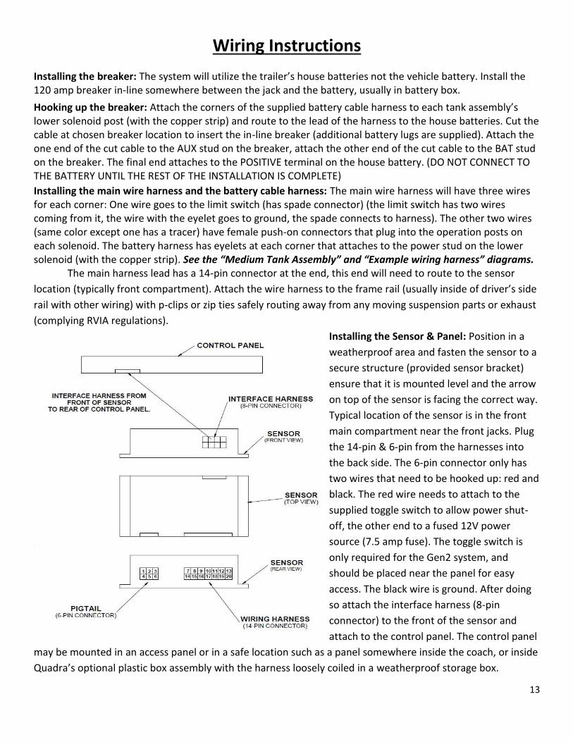
Installing the Sensor & Panel: Position in a
weatherproof area and fasten the sensor to a
secure structure (provided sensor bracket)
ensure that it is mounted level and the arrow
on top of the sensor is facing the correct way.
Typical location of the sensor is in the front
main compartment near the front jacks. Plug
the 14-pin & 6-pin from the harnesses into
the back side. The 6-pin connector only has
two wires that need to be hooked up: red and
black. The red wire needs to attach to the
supplied toggle switch to allow power shut-
off, the other end to a fused 12V power
source (7.5 amp fuse). The toggle switch is
only required for the Gen2 system, and
should be placed near the panel for easy
access. The black wire is ground. After doing
so attach the interface harness (8-pin
connector) to the front of the sensor and
attach to the control panel. The control panel
may be mounted in an access panel or in a safe location such as a panel somewhere inside the coach, or inside
Quadra’s optional plastic box assembly with the harness loosely coiled in a weatherproof storage box.
14
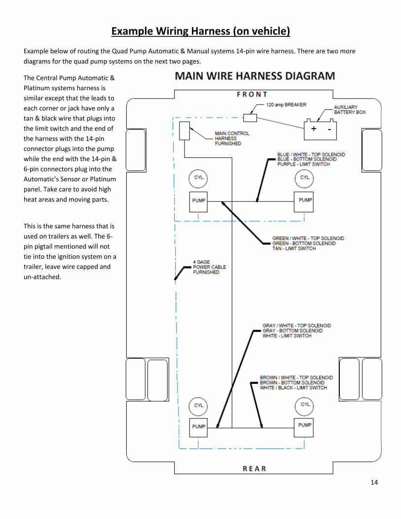
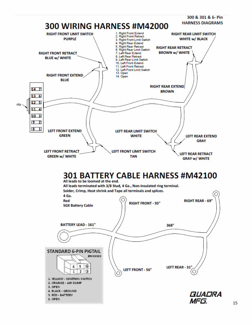
Example Wiring Harness (on vehicle)
Example below of routing the Quad Pump Automatic & Manual systems 14-pin wire harness. There are two more
diagrams for the quad pump systems on the next two pages.
The Central Pump Automatic &
Platinum systems harness is
similar except that the leads to
each corner or jack have only a
tan & black wire that plugs into
the limit switch and the end of
the harness with the 14-pin
connector plugs into the pump
while the end with the 14-pin &
6-pin connectors plug into the
Automatic’s Sensor or Platinum
panel. Take care to avoid high
heat areas and moving parts.
This is the same harness that is
used on trailers as well. The 6-
pin pigtail mentioned will not
tie into the ignition system on a
trailer, leave wire capped and
un-attached.
15
16
17
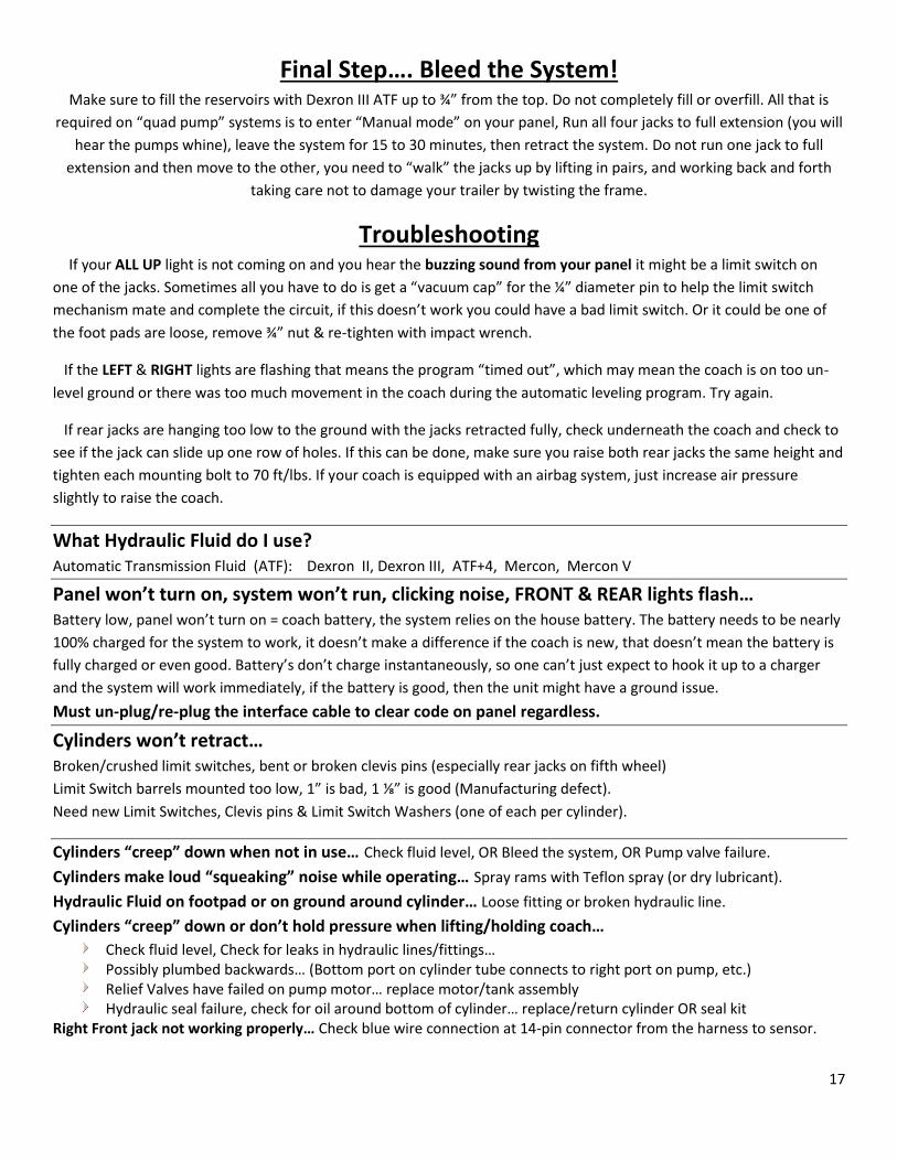
Final Step…. Bleed the System! Make sure to fill the reservoirs with Dexron III ATF up to ¾” from the top. Do not completely fill or overfill. All that is
required on “quad pump” systems is to enter “Manual mode” on your panel, Run all four jacks to full extension (you will
hear the pumps whine), leave the system for 15 to 30 minutes, then retract the system. Do not run one jack to full
extension and then move to the other, you need to “walk” the jacks up by lifting in pairs, and working back and forth
taking care not to damage your trailer by twisting the frame.
Troubleshooting If your ALL UP light is not coming on and you hear the buzzing sound from your panel it might be a limit switch on
one of the jacks. Sometimes all you have to do is get a “vacuum cap” for the ¼” diameter pin to help the limit switch
mechanism mate and complete the circuit, if this doesn’t work you could have a bad limit switch. Or it could be one of
the foot pads are loose, remove ¾” nut & re-tighten with impact wrench.
If the LEFT & RIGHT lights are flashing that means the program “timed out”, which may mean the coach is on too un-
level ground or there was too much movement in the coach during the automatic leveling program. Try again.
If rear jacks are hanging too low to the ground with the jacks retracted fully, check underneath the coach and check to
see if the jack can slide up one row of holes. If this can be done, make sure you raise both rear jacks the same height and
tighten each mounting bolt to 70 ft/lbs. If your coach is equipped with an airbag system, just increase air pressure
slightly to raise the coach.
What Hydraulic Fluid do I use? Automatic Transmission Fluid (ATF): Dexron II, Dexron III, ATF+4, Mercon, Mercon V
Panel won’t turn on, system won’t run, clicking noise, FRONT & REAR lights flash… Battery low, panel won’t turn on = coach battery, the system relies on the house battery. The battery needs to be nearly
100% charged for the system to work, it doesn’t make a difference if the coach is new, that doesn’t mean the battery is
fully charged or even good. Battery’s don’t charge instantaneously, so one can’t just expect to hook it up to a charger
and the system will work immediately, if the battery is good, then the unit might have a ground issue.
Must un-plug/re-plug the interface cable to clear code on panel regardless.
Cylinders won’t retract… Broken/crushed limit switches, bent or broken clevis pins (especially rear jacks on fifth wheel)
Limit Switch barrels mounted too low, 1” is bad, 1 ⅛” is good (Manufacturing defect).
Need new Limit Switches, Clevis pins & Limit Switch Washers (one of each per cylinder).
Cylinders “creep” down when not in use… Check fluid level, OR Bleed the system, OR Pump valve failure. Cylinders make loud “squeaking” noise while operating… Spray rams with Teflon spray (or dry lubricant). Hydraulic Fluid on footpad or on ground around cylinder… Loose fitting or broken hydraulic line.
Cylinders “creep” down or don’t hold pressure when lifting/holding coach…
Check fluid level, Check for leaks in hydraulic lines/fittings… Possibly plumbed backwards… (Bottom port on cylinder tube connects to right port on pump, etc.) Relief Valves have failed on pump motor… replace motor/tank assembly Hydraulic seal failure, check for oil around bottom of cylinder… replace/return cylinder OR seal kit
Right Front jack not working properly… Check blue wire connection at 14-pin connector from the harness to sensor.
18
Warranty Guide
4-6pt Automatic Quad Pump Systems: One year parts and labor from vehicle service date.
1pt & 2pt Round Leg Stabilizing/Landing Gear Systems: One year parts and labor. Should the product be defective due to workmanship and/or material flaws, we will repair/replace the defective
material. Core charges may be applied and refunded on certain components.
Quadra is NOT responsible for:
Freight on warranty parts.
Replacing footpads, bolts, or fluids lost as a result of failure to maintain the system (Loose footpads
should be tightened at owner’s expense).
Damages caused by abuse, misuse, negligence, misapplication, error of operation, accidental
or purposeful damage or faulty installation. Including but limited to hoses, fittings & wiring
components.
Liability for loss to the vehicle, or apparatus or property, loss of time, manufacturing costs, labor,
material, loss of profits, consequential damages (direct or indirect).
For transportation to and from a service center, onsite service calls to or from the customer, damage
from road hazard, loss of salaries, commissions, lodging, towing charges, bus fares, car rentals, fuel
expense, telephone charges, inconvenience compensation while repairing or replacing a defective
part or material.
This warranty voids all previous issues. Effective date: 7/1/15
OWNERSHIP MUST BE REGISTERED WITHIN 30 DAYS FROM THE DATE OF PURCHASE TO
ACTIVATE WARRANTY. Do it online at BIGFOOTLEVELER.com!
Prior to any work being done an authorization number must be obtained by calling
269-483-9633 for Warranty Parts or Service Labor. For full warranty transcript just contact us!
Service labor based on a flat rate schedule determined by Quadra for authorized work performed will
be reimbursed. This will eliminate much diagnostic time and avoid refusal of unauthorized claims. Many
problems may be resolved by contacting a Quadra service representative.
Provide the system serial number here .
Emergency Service Visit our website at bigfootleveler.com
Or call our normal office number
269-483-9633 and follow the instructions.