Embed Size (px)
Citation preview
Convective Heat Transfer and Reference Free-stream
Temperature Determination near the Casing of an Axial Flow Turbine
B. Gumusel2 and C. Camci1
Turbomachinery Aero-Heat Transfer Laboratory Department of Aerospace Engineering
The Pennsylvania State University 223 Hammond Building, University Park, PA 16802
ABSTRACT The present study explains a steady-state method of measuring convective heat transfer
coefficient on the casing of an axial flow turbine. The goal is to develop an accurate
steady-state heat transfer method for the comparison of various casing surface and tip
designs used for turbine performance improvements. The free-stream reference
temperature, especially in the tip gap region of the casing varies monotonically from the
rotor inlet to rotor exit due to work extraction in the stage. In a heat transfer problem of
this nature, the definition of the free-stream temperature is not as straight forward as
constant free-stream temperature type problems. The accurate determination of the
convective heat transfer coefficient depends on the magnitude of the local free-stream
reference temperature varying in axial direction, from the rotor inlet to exit. The current
study explains a strategy for the simultaneous determination of the steady-state heat
transfer coefficient and free-stream reference temperature on the smooth casing of a
single stage rotating turbine facility. The heat transfer approach is also applicable to
casing surfaces that have surface treatments for tip leakage control. The overall
uncertainty of the method developed is between 5 % and 8 % of the convective heat
transfer coefficient.
1 Cengiz Camci, Prof. of Aerospace Engineering, ASME fellow 2 Baris Gumusel, Graduate Research Assistant
INTRODUCTION Convective heat transfer to the static casing of a shroudless HP turbine rotor is a
complex aero-thermal problem. The unsteady flow with a relatively high Reynolds
number in the tip gap region has strong dependency on the tip clearance gap, blade tip
profile; tip loading conditions, tip geometry and casing surface character. Thermal
transport by flow near the casing inner surface is influenced by the unsteadiness, the
surface roughness character and the turbulent flow characteristics of the fluid entering
into the region between the tip and casing. Since the turbine inlet temperatures are
continuously elevated to higher levels, casing and tip related heat transfer issues are
becoming more critical in design studies.
In gas turbines, the gas stream leaving the combustor is not at a uniform
temperature in radial and circumferential directions. According to Butler et al [1] the
combustor exit maximum temperature can be twice as high as the minimum temperature.
The maximum temperature in general is around the mid-span and the lowest gas
temperatures are near the walls. The mechanisms related to the distortion of the radial
temperature profile as the combustor exit fluid passes through a turbine rotor are
complex, as explained by Sharma and Stetson [2] and Harvey [3]. The hottest part of the
fluid leaving the upstream nozzle guide vane tends to migrate to the rotor tip corner near
the mid pressure surface of the blade. Unfortunately, mostly the hottest fluid originating
from the mid span region of the combustor or NGV finds its way to the pressure side
corner of the blade tip in the rotating frame. Details of hot streak migration in gas
turbines can be found in Roback&Dring [4,5], Takanashi&Ni [6], Dorney et al. [7] and
Dorney&Schwab [8].
Due to significant energy extraction in a HP turbine stage, rotor absolute total
temperature monotonically decreases in axial direction at a significant rate. This is
especially true at the core of the blade passage where most of the energy extraction takes
place. However, the fluid finding its way to the area between the casing and blade tips do
not participate in the work generation as much as the mid-span fluid. Therefore, it is
reasonable to accept that the near-casing fluid does not cool as much as the mid-span
fluid when it progresses from rotor inlet to exit.
Yoshino [9] and Thorpe et al. [10] have shown that a rotor blade can also perform
work on the fluid near the casing surface by means of “rotor compressive heating”. They
obtained time-accurate and phase-locked casing heat flux measurements in Oxford Rotor
Facility to show the casing heat loads as the rotor blades move relative to the static
casing. They observed a very high heat flux zone on the casing inner surface for each
blade in the rotor. Phase-locked measurements clearly indicated that the hot spot moved
along the casing with the rotor. The results of this study showed two distinct levels of
casing heating, one level for the casing interaction with the tip leakage fluid and a
relatively low level for the casing interaction with the passage fluid located between
blade tips. Thorpe et al. [10] explained the high heat flux zone on the casing surface by a
“rotor compressive heating” model. They showed that the static pressure field near the tip
can do work on the leakage fluid trapped between the blade tip and the casing. The
“rotor compressive heating” model predicts that the absolute total temperature of the
leakage fluid may exceed that of the rotor inlet flow. The flow near the casing turns and
accelerates the leakage fluid to a tangential velocity level that is measurably above the
rotor inlet level. Thorpe et al. [11] were successful in predicting the total temperature
penalty due to compressive heating using the Euler work equation. Any design effort that
will reduce the tip leakage mass flow rate in an axial turbine will also result in the
reduction of the total temperature penalty and a corresponding reduction in casing heat
load.
Past studies show three significant contributors to casing heat loads in shroudless
HP turbines.
1. Radially outward and axial migration of a hot streak in each passage results in
the accumulation of relatively high temperature fluid near the pressure side corner of the
blade tip before it enters the tip gap.
2. A relatively higher total temperature in the near-casing fluid is observed because
the near casing fluid does not participate in stage work generation. The leakage fluid does
not expand as much as the core-flow in the rotor passage.
3. Rotor compressive heating performed by blade tips when they move against the
static casing is significant.
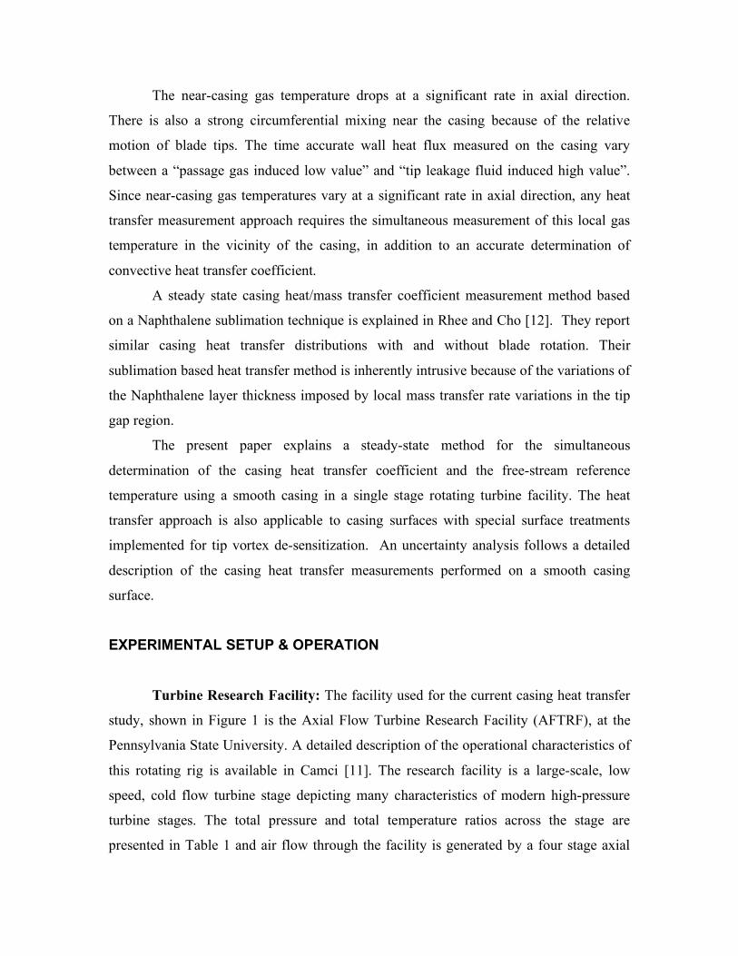
The near-casing gas temperature drops at a significant rate in axial direction.
There is also a strong circumferential mixing near the casing because of the relative
motion of blade tips. The time accurate wall heat flux measured on the casing vary
between a “passage gas induced low value” and “tip leakage fluid induced high value”.
Since near-casing gas temperatures vary at a significant rate in axial direction, any heat
transfer measurement approach requires the simultaneous measurement of this local gas
temperature in the vicinity of the casing, in addition to an accurate determination of
convective heat transfer coefficient.
A steady state casing heat/mass transfer coefficient measurement method based
on a Naphthalene sublimation technique is explained in Rhee and Cho [12]. They report
similar casing heat transfer distributions with and without blade rotation. Their
sublimation based heat transfer method is inherently intrusive because of the variations of
the Naphthalene layer thickness imposed by local mass transfer rate variations in the tip
gap region.
The present paper explains a steady-state method for the simultaneous
determination of the casing heat transfer coefficient and the free-stream reference
temperature using a smooth casing in a single stage rotating turbine facility. The heat
transfer approach is also applicable to casing surfaces with special surface treatments
implemented for tip vortex de-sensitization. An uncertainty analysis follows a detailed
description of the casing heat transfer measurements performed on a smooth casing
surface.
EXPERIMENTAL SETUP & OPERATION
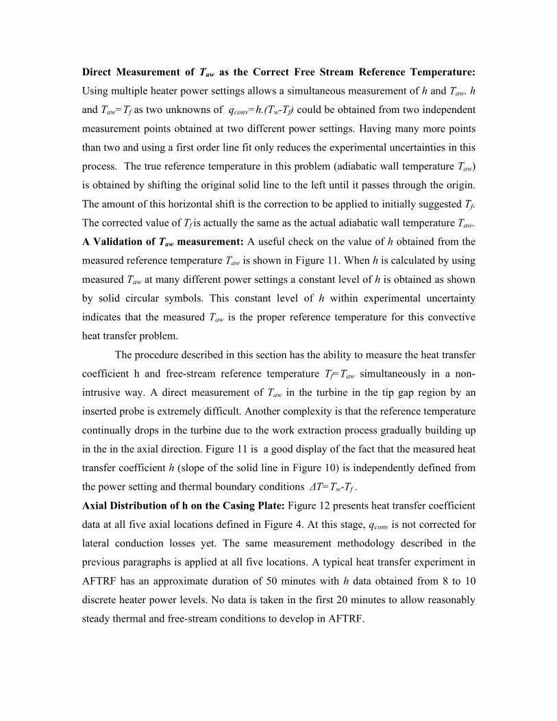
Turbine Research Facility: The facility used for the current casing heat transfer
study, shown in Figure 1 is the Axial Flow Turbine Research Facility (AFTRF), at the
Pennsylvania State University. A detailed description of the operational characteristics of
this rotating rig is available in Camci [11]. The research facility is a large-scale, low
speed, cold flow turbine stage depicting many characteristics of modern high-pressure
turbine stages. The total pressure and total temperature ratios across the stage are
presented in Table 1 and air flow through the facility is generated by a four stage axial
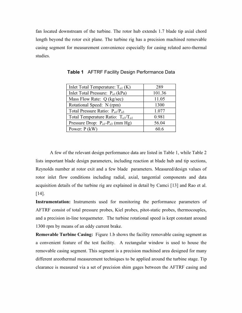
fan located downstream of the turbine. The rotor hub extends 1.7 blade tip axial chord
length beyond the rotor exit plane. The turbine rig has a precision machined removable
casing segment for measurement convenience especially for casing related aero-thermal
studies.
Table 1 AFTRF Facility Design Performance Data
A few of the relevant design performance data are listed in Table 1, while Table 2
lists important blade design parameters, including reaction at blade hub and tip sections,
Reynolds number at rotor exit and a few blade parameters. Measured/design values of
rotor inlet flow conditions including radial, axial, tangential components and data
acquisition details of the turbine rig are explained in detail by Camci [13] and Rao et al.
[14].
Instrumentation: Instruments used for monitoring the performance parameters of
AFTRF consist of total pressure probes, Kiel probes, pitot-static probes, thermocouples,
and a precision in-line torquemeter. The turbine rotational speed is kept constant around
1300 rpm by means of an eddy current brake.
Removable Turbine Casing: Figure 1.b shows the facility removable casing segment as
a convenient feature of the test facility. A rectangular window is used to house the
removable casing segment. This segment is a precision machined area designed for many
different areothermal measurement techniques to be applied around the turbine stage. Tip
clearance is measured via a set of precision shim gages between the AFTRF casing and
Inlet Total Temperature: To1 (K) 289 Inlet Total Pressure: Po1 (kPa) 101.36 Mass Flow Rate: Q (kg/sec) 11.05 Rotational Speed: N (rpm) 1300 Total Pressure Ratio: Po1/Po3 1.077 Total Temperature Ratio: To3/To1 0.981 Pressure Drop: Po1-Po3 (mm Hg) 56.04 Power: P (kW) 60.6
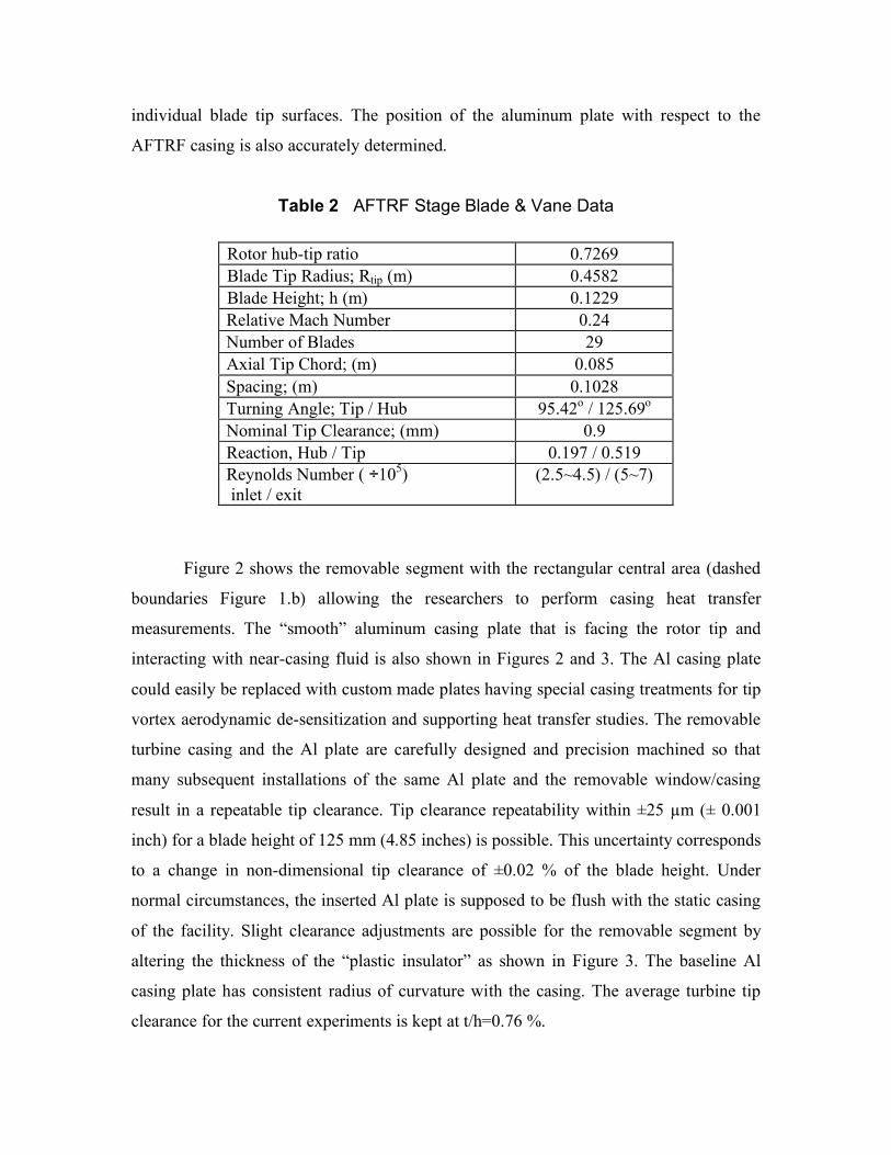
individual blade tip surfaces. The position of the aluminum plate with respect to the
AFTRF casing is also accurately determined.
Table 2 AFTRF Stage Blade & Vane Data
Figure 2 shows the removable segment with the rectangular central area (dashed
boundaries Figure 1.b) allowing the researchers to perform casing heat transfer
measurements. The “smooth” aluminum casing plate that is facing the rotor tip and
interacting with near-casing fluid is also shown in Figures 2 and 3. The Al casing plate
could easily be replaced with custom made plates having special casing treatments for tip
vortex aerodynamic de-sensitization and supporting heat transfer studies. The removable
turbine casing and the Al plate are carefully designed and precision machined so that
many subsequent installations of the same Al plate and the removable window/casing
result in a repeatable tip clearance. Tip clearance repeatability within ±25 µm (± 0.001
inch) for a blade height of 125 mm (4.85 inches) is possible. This uncertainty corresponds
to a change in non-dimensional tip clearance of ±0.02 % of the blade height. Under
normal circumstances, the inserted Al plate is supposed to be flush with the static casing
of the facility. Slight clearance adjustments are possible for the removable segment by
altering the thickness of the “plastic insulator” as shown in Figure 3. The baseline Al
casing plate has consistent radius of curvature with the casing. The average turbine tip
clearance for the current experiments is kept at t/h=0.76 %.
Rotor hub-tip ratio 0.7269 Blade Tip Radius; Rtip (m) 0.4582 Blade Height; h (m) 0.1229 Relative Mach Number 0.24 Number of Blades 29 Axial Tip Chord; (m) 0.085 Spacing; (m) 0.1028 Turning Angle; Tip / Hub 95.42o / 125.69o
Nominal Tip Clearance; (mm) 0.9 Reaction, Hub / Tip 0.197 / 0.519 Reynolds Number ( ÷105) inlet / exit
(2.5~4.5) / (5~7)
Heat Transfer Coefficient Measurement Locations: The five convective heat transfer
coefficient measurement locations are shown in Figure 4. Location 1 is closest to the
leading edge of the blade in axial direction. The five selected measurement locations
cover the axial distance between the blade leading edge and slightly downstream of the
trailing edge. Due to the rotation of the blade, the steady-state heat transfer coefficient
distribution in circumferential direction is reasonably uniform. Since work is extracted in
the rotor, the free-stream total temperature between the rotor inlet and rotor exit are
different. Free-stream total temperature measurement locations at the turbine inlet, rotor
inlet, rotor exit and turbine exit are also shown in Figure 4. The free-stream total
temperatures at turbine inlet and exit are measured using calibrated K type thermo-
couples in a Kiel probe arrangement. Rotor inlet and exit thermocouples are inserted into
the flow at about 25 mm away from the casing surface.
Steady-state Heat Transfer Method: Casing convective heat transfer coefficients and
corresponding free-stream reference temperatures are measured simultaneously with the
help of a constant heat flux heater as shown in Figure 5. A constant heat flux heater
(MINCO Corp. HK5175R176L12B) with an effective area of (A=76x127 mm2) is
sandwiched between two thin Mylar sheets. The heater can produce a maximum of 75
Watts with an overall resistance of 176 ohms. The overall resistance of the 0.5 mm thick
heater has extremely small temperature dependency in the range of the current
experiments. This resistance value is continuously measured and recorded during each
measurement. The Joule heating value in the heater is I2R/A [Watts/m2]. The heat transfer
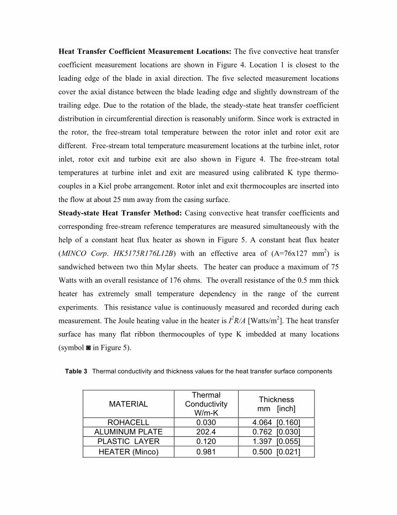
surface has many flat ribbon thermocouples of type K imbedded at many locations
(symbol ◙ in Figure 5).
Table 3 Thermal conductivity and thickness values for the heat transfer surface components
MATERIAL Thermal
Conductivity W/m-K
Thickness mm [inch]
ROHACELL 0.030 4.064 [0.160] ALUMINUM PLATE 202.4 0.762 [0.030] PLASTIC LAYER 0.120 1.397 [0.055] HEATER (Minco) 0.981 0.500 [0.021]
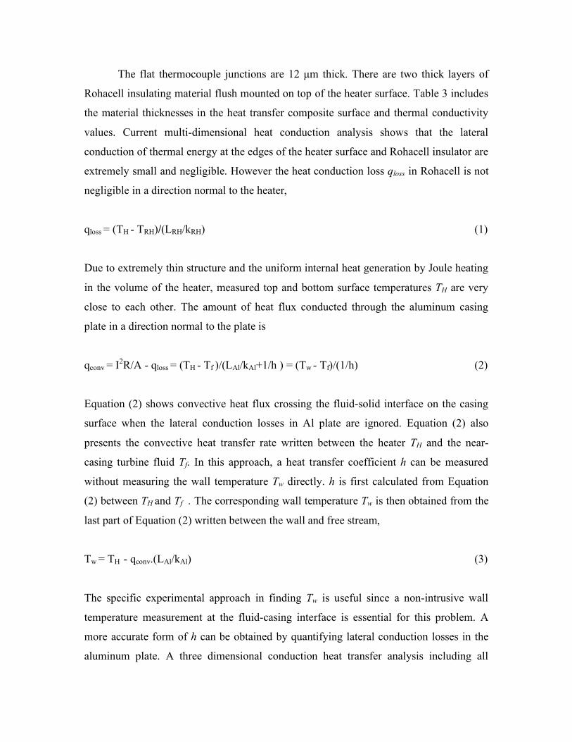
The flat thermocouple junctions are 12 µm thick. There are two thick layers of
Rohacell insulating material flush mounted on top of the heater surface. Table 3 includes
the material thicknesses in the heat transfer composite surface and thermal conductivity
values. Current multi-dimensional heat conduction analysis shows that the lateral
conduction of thermal energy at the edges of the heater surface and Rohacell insulator are
extremely small and negligible. However the heat conduction loss qloss in Rohacell is not
negligible in a direction normal to the heater,
qloss = (TH - TRH)/(LRH/kRH) (1)
Due to extremely thin structure and the uniform internal heat generation by Joule heating
in the volume of the heater, measured top and bottom surface temperatures TH are very
close to each other. The amount of heat flux conducted through the aluminum casing
plate in a direction normal to the plate is
qconv = I2R/A - qloss = (TH - Tf )/(LAl/kAl+1/h ) = (Tw - Tf)/(1/h) (2)
Equation (2) shows convective heat flux crossing the fluid-solid interface on the casing
surface when the lateral conduction losses in Al plate are ignored. Equation (2) also
presents the convective heat transfer rate written between the heater TH and the near-
casing turbine fluid Tf. In this approach, a heat transfer coefficient h can be measured
without measuring the wall temperature Tw directly. h is first calculated from Equation
(2) between TH and Tf . The corresponding wall temperature Tw is then obtained from the
last part of Equation (2) written between the wall and free stream,
Tw = TH - qconv.(LAl/kAl) (3)
The specific experimental approach in finding Tw is useful since a non-intrusive wall
temperature measurement at the fluid-casing interface is essential for this problem. A
more accurate form of h can be obtained by quantifying lateral conduction losses in the
aluminum plate. A three dimensional conduction heat transfer analysis including all
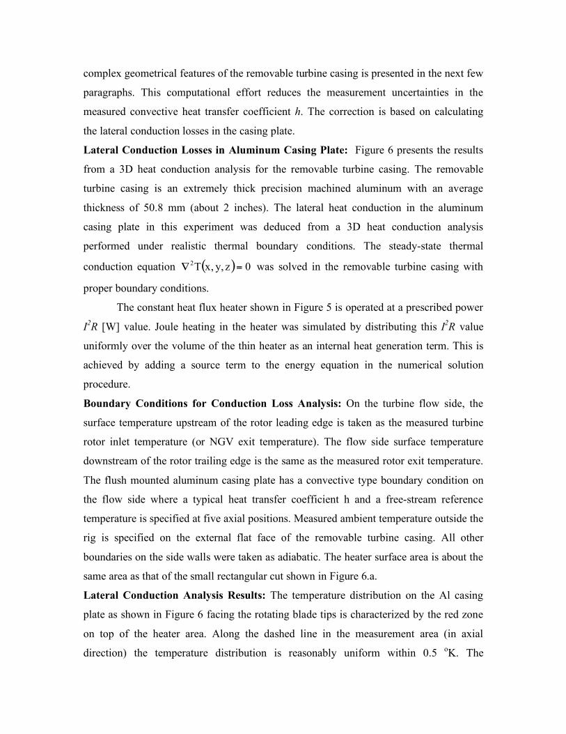
complex geometrical features of the removable turbine casing is presented in the next few
paragraphs. This computational effort reduces the measurement uncertainties in the
measured convective heat transfer coefficient h. The correction is based on calculating
the lateral conduction losses in the casing plate.
Lateral Conduction Losses in Aluminum Casing Plate: Figure 6 presents the results
from a 3D heat conduction analysis for the removable turbine casing. The removable
turbine casing is an extremely thick precision machined aluminum with an average
thickness of 50.8 mm (about 2 inches). The lateral heat conduction in the aluminum
casing plate in this experiment was deduced from a 3D heat conduction analysis
performed under realistic thermal boundary conditions. The steady-state thermal
conduction equation ( ) 0z,y,xT2 =! was solved in the removable turbine casing with
proper boundary conditions.
The constant heat flux heater shown in Figure 5 is operated at a prescribed power
I2R [W] value. Joule heating in the heater was simulated by distributing this I2R value
uniformly over the volume of the thin heater as an internal heat generation term. This is
achieved by adding a source term to the energy equation in the numerical solution
procedure.
Boundary Conditions for Conduction Loss Analysis: On the turbine flow side, the
surface temperature upstream of the rotor leading edge is taken as the measured turbine
rotor inlet temperature (or NGV exit temperature). The flow side surface temperature
downstream of the rotor trailing edge is the same as the measured rotor exit temperature.
The flush mounted aluminum casing plate has a convective type boundary condition on
the flow side where a typical heat transfer coefficient h and a free-stream reference
temperature is specified at five axial positions. Measured ambient temperature outside the
rig is specified on the external flat face of the removable turbine casing. All other
boundaries on the side walls were taken as adiabatic. The heater surface area is about the
same area as that of the small rectangular cut shown in Figure 6.a.
Lateral Conduction Analysis Results: The temperature distribution on the Al casing
plate as shown in Figure 6 facing the rotating blade tips is characterized by the red zone
on top of the heater area. Along the dashed line in the measurement area (in axial
direction) the temperature distribution is reasonably uniform within 0.5 oK. The
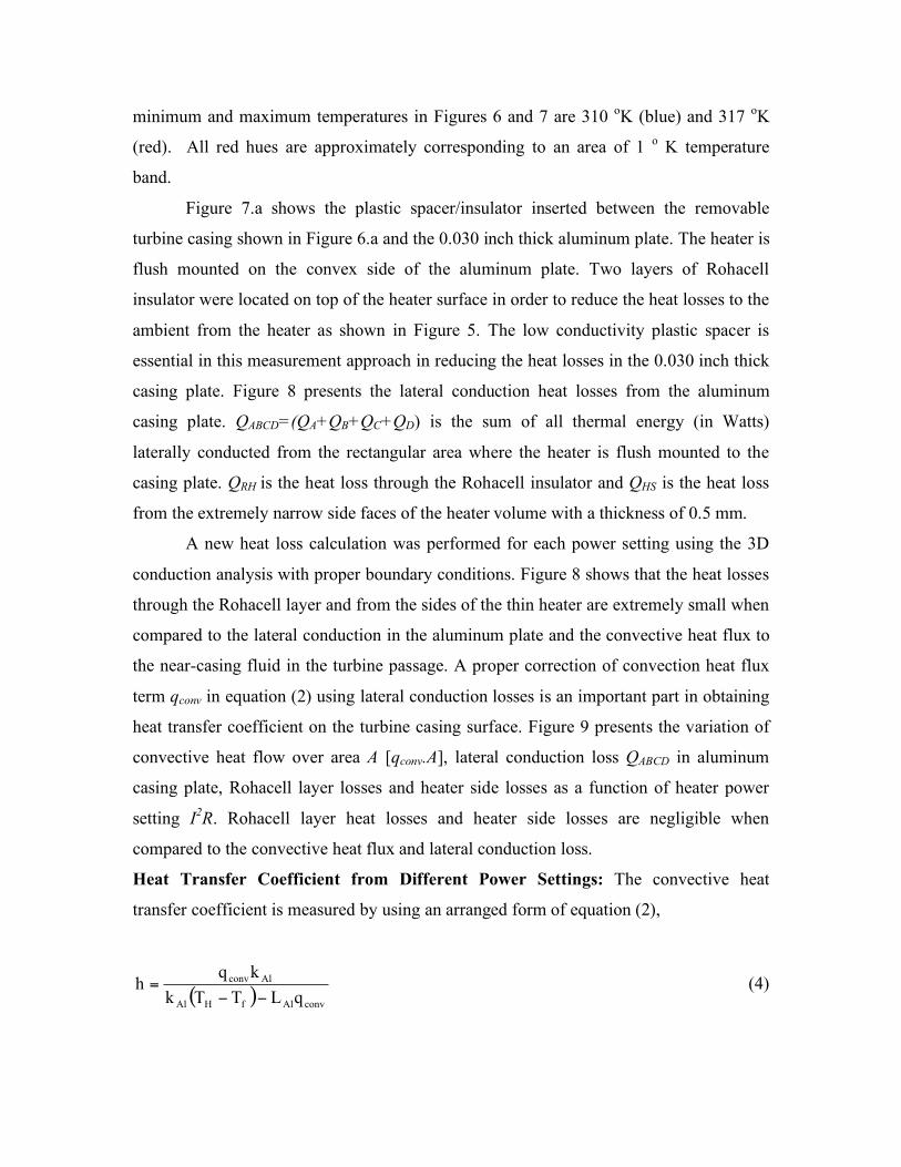
minimum and maximum temperatures in Figures 6 and 7 are 310 oK (blue) and 317 oK
(red). All red hues are approximately corresponding to an area of 1 o K temperature
band.
Figure 7.a shows the plastic spacer/insulator inserted between the removable
turbine casing shown in Figure 6.a and the 0.030 inch thick aluminum plate. The heater is
flush mounted on the convex side of the aluminum plate. Two layers of Rohacell
insulator were located on top of the heater surface in order to reduce the heat losses to the
ambient from the heater as shown in Figure 5. The low conductivity plastic spacer is
essential in this measurement approach in reducing the heat losses in the 0.030 inch thick
casing plate. Figure 8 presents the lateral conduction heat losses from the aluminum
casing plate. QABCD=(QA+QB+QC+QD) is the sum of all thermal energy (in Watts)
laterally conducted from the rectangular area where the heater is flush mounted to the
casing plate. QRH is the heat loss through the Rohacell insulator and QHS is the heat loss
from the extremely narrow side faces of the heater volume with a thickness of 0.5 mm.
A new heat loss calculation was performed for each power setting using the 3D
conduction analysis with proper boundary conditions. Figure 8 shows that the heat losses
through the Rohacell layer and from the sides of the thin heater are extremely small when
compared to the lateral conduction in the aluminum plate and the convective heat flux to
the near-casing fluid in the turbine passage. A proper correction of convection heat flux
term qconv in equation (2) using lateral conduction losses is an important part in obtaining
heat transfer coefficient on the turbine casing surface. Figure 9 presents the variation of
convective heat flow over area A [qconv.A], lateral conduction loss QABCD in aluminum
casing plate, Rohacell layer losses and heater side losses as a function of heater power
setting I2R. Rohacell layer heat losses and heater side losses are negligible when
compared to the convective heat flux and lateral conduction loss.
Heat Transfer Coefficient from Different Power Settings: The convective heat
transfer coefficient is measured by using an arranged form of equation (2),
( ) convAlfHAl
Alconv
qLTTk
kqh
!!= (4)
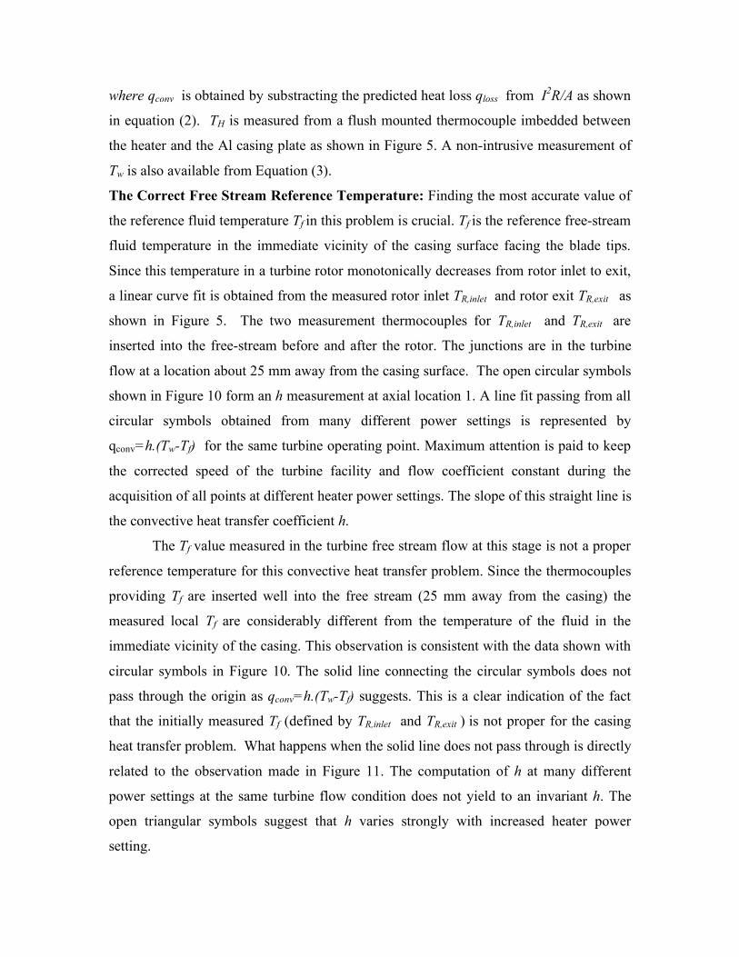
where qconv is obtained by substracting the predicted heat loss qloss from I2R/A as shown
in equation (2). TH is measured from a flush mounted thermocouple imbedded between
the heater and the Al casing plate as shown in Figure 5. A non-intrusive measurement of
Tw is also available from Equation (3).
The Correct Free Stream Reference Temperature: Finding the most accurate value of
the reference fluid temperature Tf in this problem is crucial. Tf is the reference free-stream
fluid temperature in the immediate vicinity of the casing surface facing the blade tips.
Since this temperature in a turbine rotor monotonically decreases from rotor inlet to exit,
a linear curve fit is obtained from the measured rotor inlet TR,inlet and rotor exit TR,exit as
shown in Figure 5. The two measurement thermocouples for TR,inlet and TR,exit are
inserted into the free-stream before and after the rotor. The junctions are in the turbine
flow at a location about 25 mm away from the casing surface. The open circular symbols
shown in Figure 10 form an h measurement at axial location 1. A line fit passing from all
circular symbols obtained from many different power settings is represented by
qconv=h.(Tw-Tf) for the same turbine operating point. Maximum attention is paid to keep
the corrected speed of the turbine facility and flow coefficient constant during the
acquisition of all points at different heater power settings. The slope of this straight line is
the convective heat transfer coefficient h.
The Tf value measured in the turbine free stream flow at this stage is not a proper
reference temperature for this convective heat transfer problem. Since the thermocouples
providing Tf are inserted well into the free stream (25 mm away from the casing) the
measured local Tf are considerably different from the temperature of the fluid in the
immediate vicinity of the casing. This observation is consistent with the data shown with
circular symbols in Figure 10. The solid line connecting the circular symbols does not
pass through the origin as qconv=h.(Tw-Tf) suggests. This is a clear indication of the fact
that the initially measured Tf (defined by TR,inlet and TR,exit ) is not proper for the casing
heat transfer problem. What happens when the solid line does not pass through is directly
related to the observation made in Figure 11. The computation of h at many different
power settings at the same turbine flow condition does not yield to an invariant h. The
open triangular symbols suggest that h varies strongly with increased heater power
setting.
Direct Measurement of Taw as the Correct Free Stream Reference Temperature:
Using multiple heater power settings allows a simultaneous measurement of h and Taw. h
and Taw=Tf as two unknowns of qconv=h.(Tw-Tf) could be obtained from two independent
measurement points obtained at two different power settings. Having many more points
than two and using a first order line fit only reduces the experimental uncertainties in this
process. The true reference temperature in this problem (adiabatic wall temperature Taw)
is obtained by shifting the original solid line to the left until it passes through the origin.
The amount of this horizontal shift is the correction to be applied to initially suggested Tf.
The corrected value of Tf is actually the same as the actual adiabatic wall temperature Taw.
A Validation of Taw measurement: A useful check on the value of h obtained from the
measured reference temperature Taw is shown in Figure 11. When h is calculated by using
measured Taw at many different power settings a constant level of h is obtained as shown
by solid circular symbols. This constant level of h within experimental uncertainty
indicates that the measured Taw is the proper reference temperature for this convective
heat transfer problem.
The procedure described in this section has the ability to measure the heat transfer
coefficient h and free-stream reference temperature Tf=Taw simultaneously in a non-
intrusive way. A direct measurement of Taw in the turbine in the tip gap region by an
inserted probe is extremely difficult. Another complexity is that the reference temperature
continually drops in the turbine due to the work extraction process gradually building up
in the in the axial direction. Figure 11 is a good display of the fact that the measured heat
transfer coefficient h (slope of the solid line in Figure 10) is independently defined from
the power setting and thermal boundary conditions ΔT=Tw-Tf .
Axial Distribution of h on the Casing Plate: Figure 12 presents heat transfer coefficient
data at all five axial locations defined in Figure 4. At this stage, qconv is not corrected for
lateral conduction losses yet. The same measurement methodology described in the
previous paragraphs is applied at all five locations. A typical heat transfer experiment in
AFTRF has an approximate duration of 50 minutes with h data obtained from 8 to 10
discrete heater power levels. No data is taken in the first 20 minutes to allow reasonably
steady thermal and free-stream conditions to develop in AFTRF.
Figure 13 shows the axial distribution of h at five axial locations on the casing
plate facing the blade tips. The solid circles represent the data before a lateral conduction
correction in the aluminum casing plate is applied. The magnitude of lateral conduction
losses are carefully determined from a 3D heat conduction analysis described in Figures 6
to 9. A proper heat loss analysis was performed for each power setting level carefully. A
significant change in the overall magnitude of the heat transfer coefficients is observed
after taking into account all energy losses from the Al casing plate, especially the lateral
conduction losses. The casing plate measurement locations see the subsequent passage of
tip leakage related fluid and passage fluid at blade passing frequency. The circumferential
mixing in this near casing area is inevitable. A proper lateral conduction calculation is
essential to reduce the experimental uncertainties in this heat transfer measurement
approach.
Experimental Uncertainty Estimates: The most significant goal of this study was to
establish a steady-state casing heat transfer measurement system with reduced
uncertainties. Since the number of parameters to be controlled in the rotating rig is much
larger than a typical wind tunnel study, a detailed uncertainty analysis is essential to
control and reduce the experimental errors. The specific uncertainty approach follows the
concepts developed by Kline and McClintock [15]. Our uncertainty analysis is based on
our uncertainty estimates on reference free-stream temperature, heater surface
temperature, thermal conductivity, plate thickness and aluminum casing lateral
conduction error.
Table 4 Uncertainty estimates
QUANTITY
MEASUREMENT ERROR Tf δTf = ± 0.15 o K
TH δTH = ± 0.15 o K
kAl δkAl = ± 0.221 W/m-K
LAl δLAl = ± 0.001” (25 micron)
qconv δqconv/qconv = ± 1% - 6%
h δh/h = ± 5% - 8%
Table 4 lists the magnitudes of all estimated basic measurement uncertainties.
Uncertainty analysis showed that very low heater power levels typically less than 1 Watt
have a tendency to increase δh/h. The lateral conduction loss could vary from 1 % to 6 %
even after numerically correcting for the lateral heat conduction. This uncertainty is
introduced to account for edge heat flux variations around a mean qconv that already
takes lateral conduction into account in a uniform way in axial direction. The uncertainty
of heat transfer coefficient is estimated to be in a range from 5 % to 8 %.
CONCLUSIONS
A steady-state method for the measurement of convective heat transfer coefficient
on the casing surface of an axial flow turbine is presented.
The current study presents a simultaneous measurement approach for both the
heat transfer coefficient and the reference temperature of the near-casing fluid.
The non-intrusive determination of the reference near-casing fluid temperature
Tf=Taw from the current method is highly effective in reducing the heat transfer
measurement uncertainty.
The method developed is very suitable for research turbine applications where the
free stream fluid continuously cools from rotor inlet to rotor exit due to work extraction.
Special attention is paid to the static casing region facing the rotor blades. The
current Taw measurement approach is a highly effective and non-intrusive approach for
the fluid layers in the immediate vicinity of the static casing.
A significant improvement of the uncertainty of h is possible by taking lateral
conduction losses in the casing plate into account. The lateral conduction losses resulting
from each power setting of the “constant heat flux heater” were numerically evaluated on
a high resolution 3D conduction grid prepared for the removable casing model.
The present method is able to take the variation of many turbine run time
parameters into account during a 50 minute run in which at least 8-10 heater power
settings are used for the measurements.

A detailed uncertainty analysis is presented. The current heat transfer
measurement method uncertainty is estimated to be between 5 % and 8 % of convective
heat transfer coefficient h.
The heat transfer evaluation of many casing surface modifications and blade tip
shape modifications are possible with the specific method presented in this paper.
Figure 1 Axial Flow Turbine Research Facility (AFTRF) a. facility schematic
b. window for the removable casing segment
HEAT TRANSFER
MEASUREMENT AREA
NGV
b
a
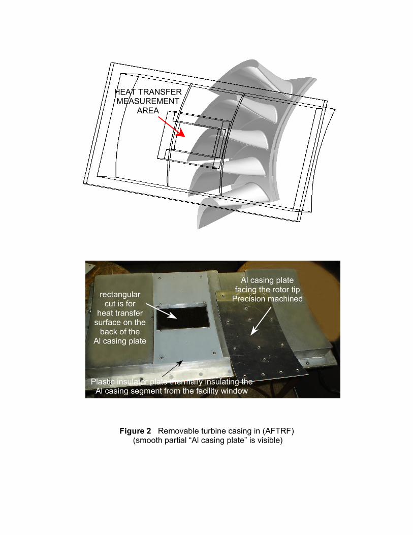
Figure 2 Removable turbine casing in (AFTRF) (smooth partial “Al casing plate” is visible)
HEAT TRANSFER MEASUREMENT
AREA
rectangular cut is for
heat transfer surface on the
back of the Al casing plate
Al casing plate facing the rotor tip
Precision machined
Plastic insulator plate thermally insulating the Al casing segment from the facility window
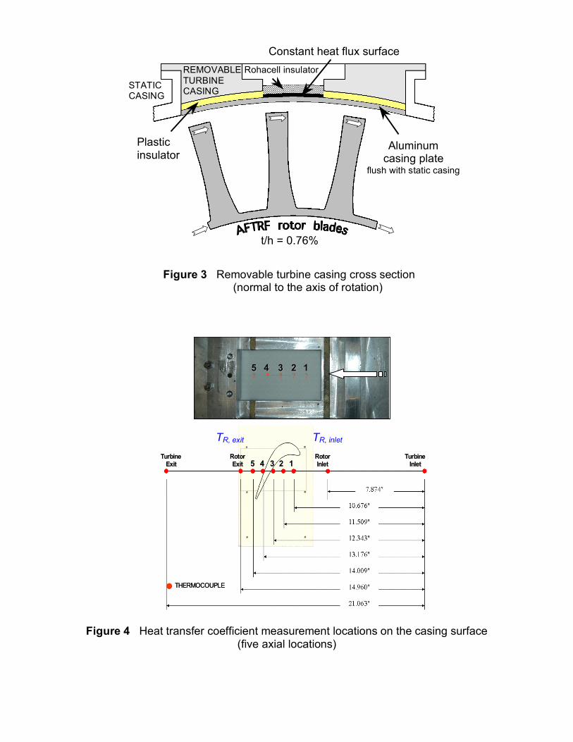
Figure 4 Heat transfer coefficient measurement locations on the casing surface
(five axial locations)
Figure 3 Removable turbine casing cross section (normal to the axis of rotation)
REMOVABLE TURBINE CASING
STATIC CASING
Rohacell insulator
Constant heat flux surface
Aluminum casing plate
flush with static casing
Plastic insulator
t/h = 0.76%
1122334455?????1122334455?????
1122334455
RotorRotor
InletInlet
RotorRotor
ExitExit
TurbineTurbine
InletInlet
TurbineTurbine
ExitExit
THERMOCOUPLETHERMOCOUPLE
TR, inlet
TR, exit
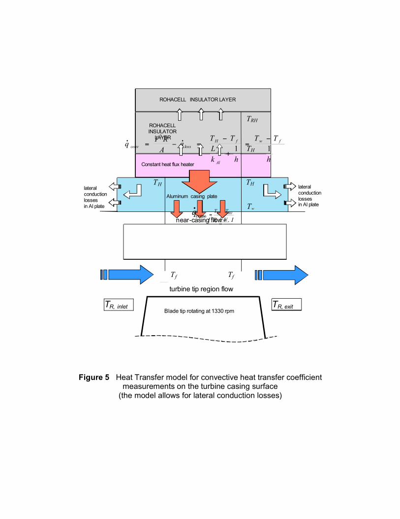
Figure 5 Heat Transfer model for convective heat transfer coefficient
measurements on the turbine casing surface (the model allows for lateral conduction losses)
lateral conduction losses in Al plate
lateral conduction losses in Al plate
A
IV
A
RI .2
=
Al
Al
Ak
L
_
_
_
_ Tw
RH
RH
RHH
loss
k
L
TTq
!=
•
TH
TH
h
TT
hk
L
TTq
A
RIq
fw
Al
Al
fH
lossconv 11
2 !=
+
!=!=
••
_
TH
_
_ Tf
TRH
ROHACELL INSULATOR LAYER
ROHACELL INSULATOR
LAYER
Constant heat flux heater
near-casing flow
turbine tip region flow
Tf
Blade tip rotating at 1330 rpm TR, inlet
TR, exit
Aluminum casing plate
convq•
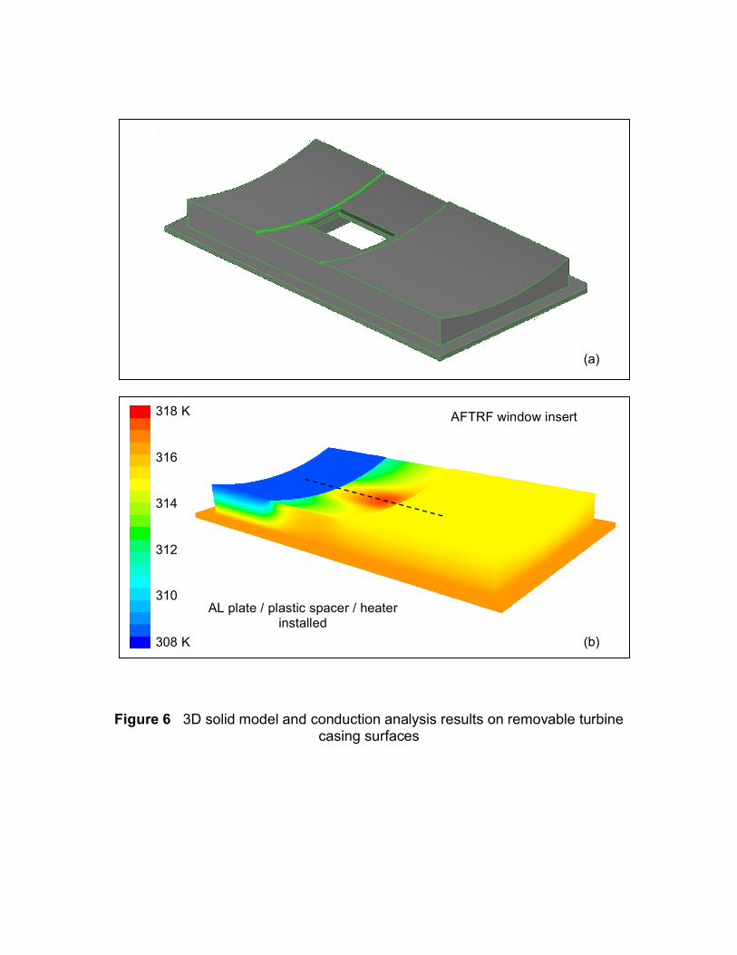
Figure 6 3D solid model and conduction analysis results on removable turbine
casing surfaces
(b)
318 K
316
314
312
310
308 K
AL plate / plastic spacer / heater installed
AFTRF window insert
(b)
(a)
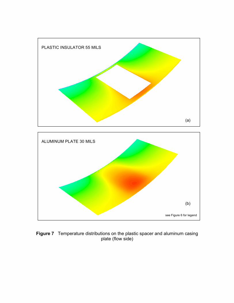
Figure 7 Temperature distributions on the plastic spacer and aluminum casing
plate (flow side)
ALUMINUM PLATE 30 MILS
see Figure 6 for legend
(b)
PLASTIC INSULATOR 55 MILS
(a)
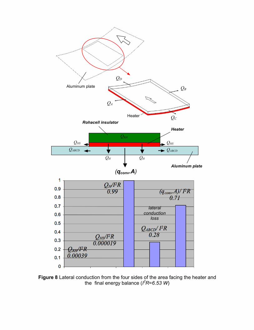
Figure 8 Lateral conduction from the four sides of the area facing the heater and
the final energy balance (I2R=6.53 W)
QA
QB
QC
QD
.
Heater
Aluminum plate
lateral conduction
loss
Heater QRH
QHS QABCD
QHS
(qconv.A)
QH QH
Rohacell insulator
QABCD
Aluminum plate
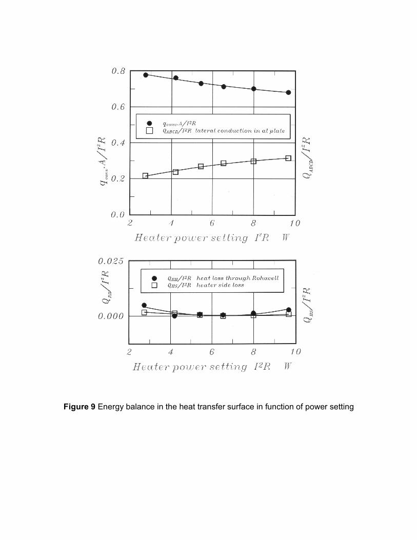
Figure 9 Energy balance in the heat transfer surface in function of power setting
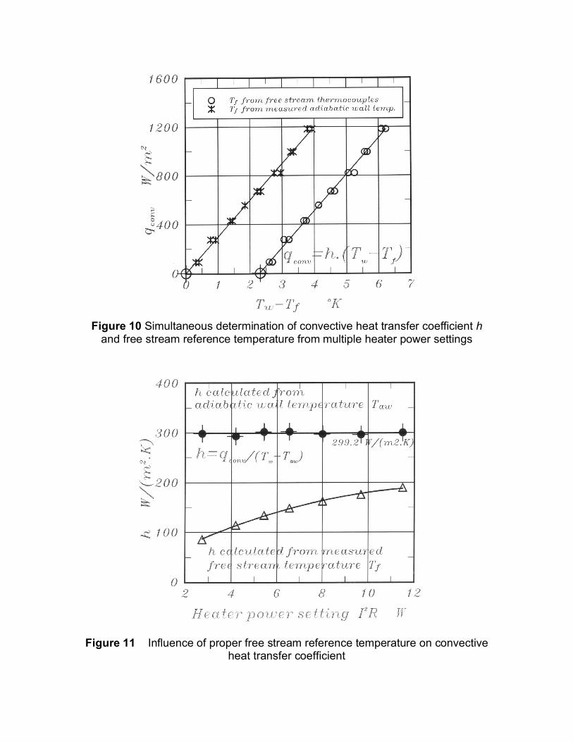
Figure 10 Simultaneous determination of convective heat transfer coefficient h and free stream reference temperature from multiple heater power settings
Figure 11 Influence of proper free stream reference temperature on convective
heat transfer coefficient
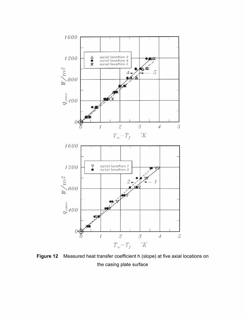
Figure 12 Measured heat transfer coefficient h (slope) at five axial locations on
the casing plate surface
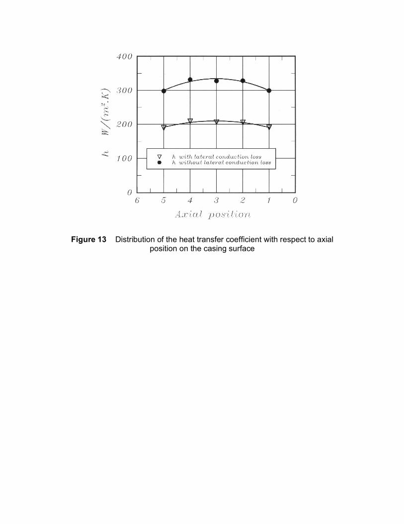
Figure 13 Distribution of the heat transfer coefficient with respect to axial
position on the casing surface
ACKNOWLEDGMENTS
The authors acknowledge the valuable comments and advice provided by Dr. R.E.Chupp
of GE Power Systems throughout this study. They are indebted to Mr.Harry Houtz, Rick
Auhl, Mark Catalano, and Kirk Hellen for their technical support. The authors also
acknowledge the valuable support from the Department of Aerospace Engineering at
Penn State University.
NOMENCLATURE A heat transfer measurement area [m2] also constant heat flux surface area h convective heat transfer coefficient [W/m2.K] h also rotor blade height I DC current level to heater I2R Joule heating in the heater [W] k thermal conductivity L material thickness N rotational speed [rpm] Po1 stage inlet total pressure, Pa Po3 stage exit total pressure, Pa P turbine power output [kW] QRH total heat flow through Rohacell insulator [W] QHS heat loss from the sides of the 0.5 mm thin heater [W] QH QH =(I2R-QRH-QHS) [W] QABCD lateral conduction loss in al casing plate [W]
(all four sides, see Figure 8) qconv convective wall heat flux [W/m2] qloss heat loss to ambient (through Rohacell) [W/m2] qconv.A convective heat flow through area A qconv.A =(QH-QABCD) [W] Q turbine mass flow rate [kg/s] r,R radius t gap height between blade tip and outer casing t/h non-dimensional average tip clearance t/h=0.76 % To1 stage inlet total temperature [K] To3 stage exit total temperature [K] Taw adiabatic wall temperature Tf Free stream reference temperature [Taw] TR,inlet free stream total temperature at rotor inlet (measured 1 25 cm away from casing) TR,exit free stream total temperature at rotor exit (measured 1 25 cm away from casing) Um rotor blade speed at mid-height location V velocity V also DC voltage applied to the heater θ,x,r tangential, axial, radial directions
subscripts aw adiabatic wall Al Aluminum f free stream fluid reference H heater RH Rohacell insulator material w wall
REFERENCES
1. Butler, T.L., Sharma O.P., Joslyn, H.T., Dring, R.P., 1989, “Redistribution of an inlet Temperature Distribution in an Axial Flow Turbine Stage”, AIAA Journal of Propulsion, .Vol.5, No.1, pp.64-71. 2. Sharma, O.P., Stetson, G.M., 1998, “Impact of Combustor Generated Temperature Distortions on Performance, Durability and Structural Integrity of Turbines”, VKI Lecture Series 1998-02, Feb.9-12, Brussels, Belgium. 3. Harvey, N.W., 2004, “Turbine Blade Tip Design and Tip Clearance Treatment”, von Karman Institute Lecture Series VKI-LS 2004-02 ISBN 2-930389-51-6, Brussels. 4. Roback, R.J., Dring, R.P., 1992, “Hot Streaks and Phantom Cooling in a Turbine Rotor Passage, Part-1 Separate Effects”, ASME paper 92-GT-75. 5. Roback, R.J., Dring, R.P., 1992, “Hot Streaks and Phantom Cooling in a Turbine Rotor Passage, Part-2 Combined Effects and Analytical Modelling”, ASME paper 92-GT-76. 6. Takanishi, R.K., Ni, R.H., 1990, “Unsteady Euler Analysis of the Redistribution of an Inlet Temperature Distortion in a Turbine, AIAA paper 90-2262. 7. Dorney, D.J., Davis, R.L., Edwards, D.E., Madavan, N.K., 1990, “Unsteady Analysis of Hot Streak Migration in a Turbine Stage”, AIAA-90-2354. 8. Dorney, D.J. and Schwab, R.J., 1995, “Unsteady Numerical Simulations of Radial Temperature Profile Redistribution in a Single Stage Turbine”, ASME paper 95-GT-178. 9. Yoshino, S., 2002, “Heat Transfer in Rotating Turbine Experiments”, D.Phil. Thesis, Oxford University. 10. Thorpe, S.J.,Yoshino, S., Ainsworth, R.W., Harvey, N.W., 2005, “The Effect of Work Processes on the Casing heat Transfer of a Transonic Turbine”, ASME Journal of Turbomachinery, Vol.128, pp. 1-8. 11. Thorpe, S.J, Yoshino, S, Ainsworth, R.W., Harvey, N.W., 2004, “An Investigation of the Heat Transfer and Static Pressure on the Over-tip Casing Wall of an Axial Turbine Operating at Engine Representative Flow Conditions: Part II, Time-resolved Results”, International Journal of Heat and Fluid Flow, Vol. 25 (6), pp. 945-960. 12. Rhee, D. and Cho, H.H., 2005, “Local Heat/Mass Transfer Characteristics on a Rotating Blade with Flat Tip in a Low Speed Annular Cascade: Part 2- Tip and Shroud”, ASME paper GT2005-68724.

13. Camci, C., 2004, “Experimental and Computational Methodology for Turbine Tip De-sensitization”, VKI Lecture Series 2004-02, Turbine Blade Tip Design and Tip Clearance Treatment, 2004. 14. Rao, M.N., Gumusel, B., Kavurmacioglu, L., and Camci, C., 2006, “Influence of Casing Roughness on the Aerodynamic Structure of Tip Vortices in an Axial Flow Turbine”, ASME paper GT 2006-91011. 15. Kline, S.J., McClintock, F.A., 1953, “Describing Uncertainties in Single-Sample Experiments”, Mechanical Engineering, Vol.75, pp. 3- 11.
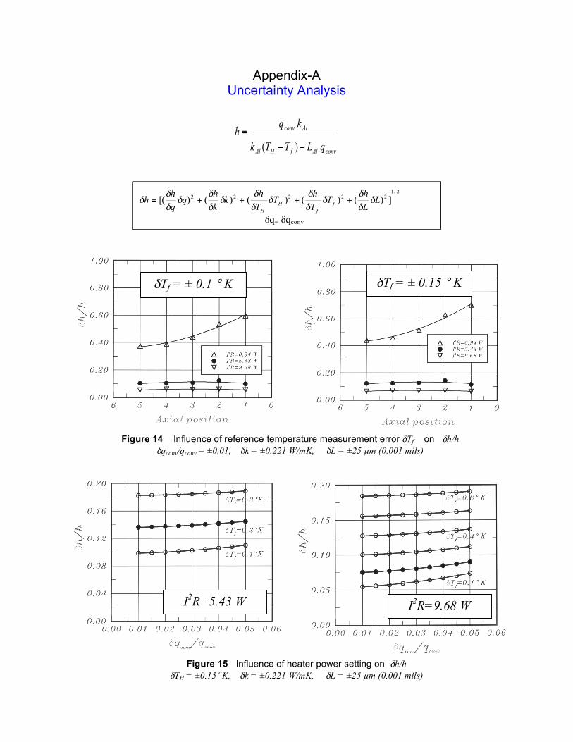
Appendix-A Uncertainty Analysis
convAlfHAl
Alconv
qLTTk
kqh
!!
=
)(
2/1
22222 ])()()()()[( LL
hT
T
hT
T
hk
k
hq
q
hh f
f
H
H
!!
!!
!
!!
!
!!
!
!!
!
!! ++++=
δq= δqconv
Figure 14 Influence of reference temperature measurement error δTf on δh/h δqconv/qconv = ±0.01, δk = ±0.221 W/mK, δL = ±25 µm (0.001 mils)
δTf = ± 0.1 ° K
δTf = ± 0.15 ° K
Figure 15 Influence of heater power setting on δh/h δTH = ±0.15 oK, δk = ±0.221 W/mK, δL = ±25 µm (0.001 mils)
I2R=5.43 W
I2R=9.68 W