Embed Size (px)
Citation preview
lable at ScienceDirect
Energy 41 (2012) 146e152
Contents lists avai
Energy
journal homepage: www.elsevier .com/locate/energy
Conventional and advanced exergetic analyses applied to a combined cycle powerplantq
Fontina Petrakopoulou*, George Tsatsaronis, Tatiana Morosuk, Anna CarassaiInstitute for Energy Engineering, Technische Universität Berlin, Marchstr. 18, 10587 Berlin, Germany
a r t i c l e i n f o
Article history:Received 30 September 2010Received in revised form19 April 2011Accepted 15 May 2011Available online 13 July 2011
Keywords:Thermodynamic inefficienciesExergy destructionConventional exergetic analysisAdvanced exergetic analysisCombined cycle power plant
q This paper is an updated version of a papeproceedings. It is printed here with permission of the* Corresponding author. Tel.: þ49 30 314 22851; fa
E-mail addresses: [email protected]@iet.tu-berlin.de (G. Tsatsaronis), [email protected] (A. Carassai).
0360-5442/$ e see front matter � 2011 Elsevier Ltd.doi:10.1016/j.energy.2011.05.028
a b s t r a c t
Conventional exergy-based methods pinpoint components and processes with high irreversibilities.However, they lack certain insight. For a given advanced technological state, there is a minimum level ofexergy destruction related to technological and/or economic constraints that is unavoidable. Further-more, in any thermodynamic system, exergy destruction stems from both component interactions(exogenous) and component inefficiencies (endogenous). To overcome the limitations of the conventionalanalyses and to increase our knowledge about a plant, advanced exergy-based analyses have beendeveloped.
In this paper, a combined cycle power plant is analyzed using both conventional and advancedexergetic analyses. Except for the expander of the gas turbine system and the high-pressure steamturbine, most of the exergy destruction in the plant components is unavoidable. This unavoidable part isconstrained by internal technological limitations, i.e. each component’s endogenous exergy destruction.High levels of endogenous exergy destruction show that component interactions do not contributesignificantly to the thermodynamic inefficiencies. In addition, these inefficiencies are unavoidable toa large extent. With the advanced analysis, new improvement strategies are revealed that could nototherwise be found.
� 2011 Elsevier Ltd. All rights reserved.
1. Introduction
Conventional exergetic, economic and exergoeconomic analysesconstitute a rigorous evaluation of energy conversion systems. Aconventional exergetic analysis reveals irreversibilities within eachcomponent of a plant. The costs related to the irreversibilities arethen estimated in an exergoeconomic analysis [1e5]. Advancedexergetic and exergoeconomic analyses are needed in order todetermine which part of the inefficiencies and the related costs iscaused by component interactions (i.e. the structure of the plant),and which part can be avoided through technological improvementsof a plant. These analyses explicitly identify the exergy destructionand costs and separate them into two main groups: (1) avoidable-unavoidable exergy destruction/cost and (2) endogenous-exogenousexergy destruction/cost. A similar strategy is possible for environ-mental impacts in an advanced exergoenvironmental analysis.
r published in the ECOS10authors and organizers.
x: þ49 30 314 21683.in.de (F. Petrakopoulou),@iet.tu-berlin.de (T. Morosuk),
All rights reserved.
Component interactions determine the exogenous exergy destructionand operating inefficiencies within the component determine theendogenous exergy destruction. Moreover, part of the overall irre-versibilities exists due to physical, technological and economicconstraints and cannot be avoided (unavoidable exergy destruction).Irreversibilities that can be prevented through design improvementsconstitute the avoidable exergy destruction. The exogenous andendogenous parts can be further split into avoidable and unavoid-able parts facilitating the understanding of component intercon-nections and the estimation of the potential for improvement. Ina similar way, the imposed costs and environmental impacts can beseparated in the advanced exergoeconomic and exergoenvir-onmental analyses, respectively. Work in this field has been con-ducted in recent years at the Technical University of Berlin [6e13].Through the classifications developed in these analyses, thecomponents that influence the performance of the overall processare identified, and the focus lies on the avoidable part of theendogenous and exogenous exergy destruction.
The present paper focuses on the application of the advancedexergetic analysis, while the advanced exergoeconomic and exer-goenvironmental analyses will be presented in subsequent publi-cations. The analysis is applied to a complex energy conversionsystem: a three-pressure-level combined cycle power plant. The

Table 1Assumptions made for calculating the theoretical processes and the unavoidableexergy destructions.
Component Theoretical conditions Unavoidable conditions
Compressor his ¼ 100% his ¼ 98%hmech ¼ 100% hmech ¼ 100%
Combustion Chamber (CC) Qloss ¼ 0 Qloss ¼ 0Dp ¼ 0 Dp ¼ 0l ¼ 2.05 l ¼ 1e ¼ 100%
Expander his ¼ 100% his ¼ 99%hmech ¼ 100% hmech ¼ 100%
Generators helectr ¼ 100% helectr ¼ 99.5%Superheaters DTmin ¼ 0 DTmin ¼ 4Reheater Dp ¼ 0 Dp ¼ 0
DTmin ¼ 0 DTmin ¼ 1Evaporators Approach Temp. ¼ 0 Approach Temp. ¼ 0
Dp ¼ 0 Dp ¼ 0Economizers DTmin ¼ 0 DTmin ¼ 1
Dp ¼ 0 Dp ¼ 0Steam his ¼ 100% his ¼ 97%Turbines hmech ¼ 100% hmech ¼ 100%Pumps his ¼ 100% his ¼ 95%
hmech ¼ 100% hmech ¼ 100%Motors helectr ¼ 100% helectr ¼ 98%
F. Petrakopoulou et al. / Energy 41 (2012) 146e152 147
main objective is to identify the most influential components, inorder to indicate changes related to (1) the structure and (2) theoperation of the plant components that will result in a more effi-cient performance of the overall plant.
2. Methodology
2.1. Conventional exergetic analysis
Through an exergetic analysis, the components with high irre-versibilities in a system are identified. Attributes and advantages ofthe exergetic analysis are well established [14].
By defining the exergy of the product, _EP;k, and the exergy of thefuel, _EP;k, for component k, we can determine its exergetic efficiency:
G
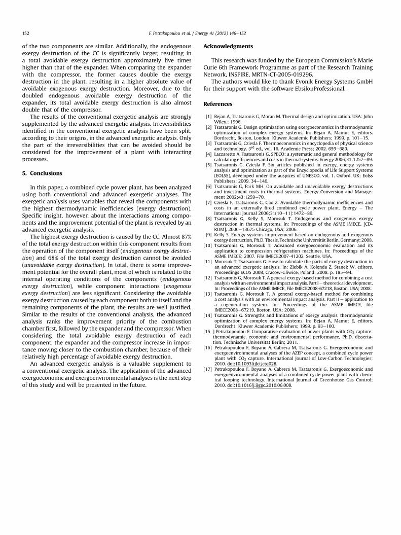
HP HRSG
IP HRSG
Gas Turbine
RH
1
2 5
6 97
8 10
11
12
13
14
40
41
42
27
28
30
31
4
44
HPSH
HPEVAP
HPECON
IPEVAPIPSH
GTCompressor
34
Mixer
CC
NG
: Air : Flue gas
: Water/ Steam : Shaft
NG: Natural Gas
HP: High PressureIP: Intermediate Pressure
LP: Low Pressure
GT: Gas TurbineCC: Combustion Chamber
ST: Steam TurbineSH: Superheater
EVAP: EvaporatorECON:Economizer
P:PumpPH: Preheater
CT: Cooling Tower
Mixer 3
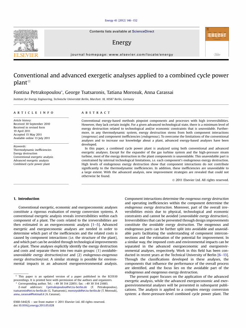
Fig. 1. Structure of the comb
ek ¼ _EP;k= _EF;k. A useful variable for comparison of dissimilarcomponents is the exergy destruction ratio defined as:yD;k ¼ _ED;k= _EF;tot, with _ED;k being the exergy destruction withincomponent k and _EF;tot the exergy of the fuel provided to the overallplant (subscript tot). The ratio yD,K is a measure of the contribution ofthe exergy destruction within component k to the reduction of theexergetic efficiency of the overall plant.
2.2. Advanced exergetic analysis
Through an advanced exergetic analysis, the exergy destruction
is split into avoidable, _EAVD , and unavoidable, _E
UND , parts as well as
into endogenous, _EEND , and exogenous, _E
EXD , parts. With this analysis,
the effects of component interactions and technological limitationson the efficiency of a system are estimated. A detailed description ofthe methodology is provided in Refs. [8,11,15], but its main princi-ples are presented below.
2.2.1. Endogenous e exogenous exergy destructionIn a system with n components, the endogenous exergy
destruction, _EEND;k, is the exergy destruction related to the operation
of component k itself. It is obtained when the considered compo-nent operates under real conditions and all other components ofthe process operate without irreversibilities (theoretically). Thepower output of the overall plant is kept constant in all estimations.The theoretical conditions for the most important components areshown in Table 1. For the combustion chamber no theoreticalconditions can be defined, due to the chemical reactions takingplace there. Different methods have been proposed to overcomethis problem [9]. One approach, proposed in Ref. [11], is valid formore complex systems and has been applied here.
In the case of the plant considered here, when either thecombustion chamber or the neighboring components operatetheoretically, streams 3 and 4 in Fig. 1 will change to maintain thepredefined (either real- or theoretical-related) exergy balance forthe reactor. When theoretical operation is assumed for a compo-nent or a group of components, the mass flows of the required air
G
M
M
M
M
M
Chimney
LP HRSG
Condenser CT
De-aerator
Steam Turbine
Pump
Condensate pump
Feedwater pumps
15 16 17 18 19
202122
2339 24
25
26
2932
33
34
35
3637
38
3
45
4649
50
IPECON LPEVAP Water PHLPSH
IPST LPSTHPST
HPPIPP
LPPMixer 1
2
4847
ined cycle power plant.
F. Petrakopoulou et al. / Energy 41 (2012) 146e152148
and fuel are calculated through the net power output of the plant,_Wnet, and the excess air fraction (l) for the combustion chamber,which have the same values as in the real case.
For calculating the endogenous exergy destruction, the CC(combustion chamber) must operate with its real exergetic effi-ciency ð _E2 þ ecc _E6 ¼ _E4; with ecc ¼ erealCC Þ, while in the theoreticalcase its exergy destruction must be set to zero ð _ED;CC ¼ 00eCC¼ 10 _E2 þ _E6 ¼ _E4Þ. The thermodynamic variables of stream 4agree with those of the real case throughout the analysis, whilethose of stream 2 vary depending on different combinations of theoperating states of the compressor (C1) and the CC. For example,when both components operate theoretically, no pressure lossesare incurred within the CC. With lower pressure losses present,stream 1 must be compressed to a lower pressure, since the inletpressure of the expander (GT) is kept constant, resulting in lowertemperatures for streams 2 and 3. Moreover, the temperatures ofstreams 2 and 3 are also decreased by the high isentropic efficiencyof the theoretical compressor. In total, there are two possiblethermodynamic states (real and theoretical) and two consideredcomponents (the CC and the compressor), thus 22 ¼ 4 possiblecombinations to take into account when defining the exergybalance of the CC. The temperature and pressure of stream 2 iscalculated for all 4 combinations and its exergy is provided as inputto the respective simulations.
After estimating the endogenous exergy destruction of compo-nent k, its exogenous exergy destruction is calculated by subtract-ing its endogenous exergy destruction from its real exergy
destruction, _ErealD;k :
_EEXD;k ¼ _E
realD;k � _E
END;k (1)
The exogenous exergy destruction, _EEXD;k, is, therefore, the exergy
destruction imposed on component k through the operation of theremaining n-1 components that constitute the overall system. The_EEXD;k of component k can also be further split, revealing the specific
components that cause it. The sum of the exogenous exergydestruction terms is different from the exogenous exergy destruc-tion of the kth component. This difference, the mexogenous exergy
destruction _EMXD;k , is caused by the simultaneous interconnections of
all (n) components and it is calculated as in Ref. [11]:
_EMXD;k ¼ _E
EXD;k �
Xnr¼1rsk
_EEX;rD;k (2)
2.2.2. Avoidable e unavoidable exergy destructionTechnological and economic design limitations determine
a minimum value of the exergy destruction. The part of theexergy destruction that cannot be avoided with technologicallyfeasible design modifications is the unavoidable exergy destruc-
tion, _EUND;k. The unavoidable exergy destruction is calculated by
considering each component in isolation, separated from thesystem, assuming the most favorable operating conditions. Theseconditions refer to minimum exergy destruction and are associ-ated with very low temperature differences and thermal/pressurelosses within the components. The assumptions for simulatingunavoidable conditions depend on the decision maker and arearbitrary to some extent. In this paper these assumptions havebeen selected based on the authors’ knowledge and experienceon plant operation and by considering the maximum improve-ment potential that could be achieved for each plant componentin the foreseeable future.
The assumptions taken into consideration for calculating theunavoidable exergy destruction are shown in Table 1. The ratio of
exergy destruction per unit of product exergy ð _E*D= _EpÞUN
k is thencalculated. For component k with exergy of the product in the real
process _ErealD;k , the unavoidable exergy destruction _E
UND;k is calculated
from
_EUND;k ¼ _E
realP;k �
� _ED_EP
�UN
k(3)
When the unavoidable exergy destruction of component k isknown, its avoidable exergy destruction is obtained with Eq. (4):
_EAVD;k ¼ _E
realD;k � _E
UND;k (4)
For the mixers, the deaerator and the condenser, no distinctionbetween avoidable and unavoidable exergy destruction has beenmade here. The mixers and the deaerator depend mainly on theoperation of the neighboring components they also present verysmall values of exergy destruction. The condenser is a dissipativecomponent and cannot be analyzed with the equations presentedhere. Thus, the evaluation must be expanded to include dissipativecomponents in the future.
2.2.3. Splitting avoidable and unavoidable exergy destruction intoendogenous and exogenous parts
The unavoidable endogenous exergy destruction, _EUN;END;k , within
component k is calculated from
_EUN;END;k ¼ _E
ENP;k �
_E*
D_EP
!UN
k
(5)
The unavoidable exogenous exergy destruction is calculatedwith Eq. (6).
_EUN;EXD;k ¼ _E
UND;k � _E
UN;END;k (6)
The avoidable endogenous and the avoidable exogenous exergydestructions are then calculated by subtracting the unavoidableendogenous and unavoidable exogenous from the total endogenousand exogenous exergy destructions, respectively:
_EAV ;END;k ¼ _E
END;k � _E
UN;END;k (7a)
and
_EAV ;EXD;k ¼ _E
EXD;k � _E
UN;EXD;k (7b)
To identify the effect of each plant component on the overallplant performance, the sum of the avoidable exergy destructionscaused by the component being considered is calculated by
_EAV ;SD;k ¼ _E
AV ;END;k þ
Xnr¼1rsk
_EAV ;EX;kD;r (8)
Pn _EAV ;EX;kD;r
r¼1rsk is the sum of the avoidable exogenous exergy dest-
ruction caused by component k within the remaining components.Each part of this sum is calculated for each component r (n s k)
separately, via the unavoidable exogenous exergy destruction, as inRef. [11]:
Table 2Calculated thermodynamic variables for selected material streams.
Stream, j _mj [kg/s] Tj [�C] pj [bar] _Etot;j [MW]
1 614.50 15.0 1.01 0.962 614.50 392.9 17.00 232.253 14.00 15.0 50.00 729.624 14.00 15.0 17.00 727.375 628.50 1264.0 16.49 741.016 628.50 580.6 1.06 189.877 268.50 580.6 1.06 81.118 268.50 447.6 1.05 54.649 360.00 580.6 1.06 108.7510 360.00 449.3 1.05 73.6811 628.50 448.6 1.05 128.3312 628.50 341.2 1.04 84.6913 628.50 257.9 1.04 55.7714 628.50 257.3 1.04 55.5915 628.50 237.6 1.04 49.4916 628.50 234.1 1.04 48.4317 628.50 229.3 1.04 47.0118 628.50 156.4 1.03 27.9819 628.50 95.3 1.03 16.4920 94.58 32.9 3.73 0.4721 94.58 135.6 3.62 8.1822 95.41 140.0 3.62 8.7923 72.43 140.0 3.62 6.6724 7.22 140.0 3.62 0.67
F. Petrakopoulou et al. / Energy 41 (2012) 146e152 149
_EUN;EN;rþkD;r ¼ _E
EN;rþkP;r
_E*
D_EP
!UN
r
(9)
_EEN;rþkP;r is the _EP of component r, when components r and k
operate under real conditions and all remaining componentsoperate under theoretical conditions.
The unavoidable exogenous exergy destruction, _EUN;EX;kD;r , in
component r due to component k is calculated from
_EUN;EX;kD;r ¼ _E
UN;EN;rþkD;r � _E
UN;END;r (10)
Finally, the avoidable exogenous exergy destruction of compo-nent r caused by component k, is found by subtracting itsunavoidable exogenous exergy destruction from its total exogenousexergy destruction:
_EAV ;EX;kD;r ¼ _E
EXD;r � _E
UN;EX;kD;r (11)
The calculation of avoidable and unavoidable values is subjec-tive and is conducted in a rather simple way. Yet the informationobtained by this approach is very valuable because it provides uswith an approximate number that shows the avoidable inefficien-cies, on which we need to focus.
25 7.22 140.5 25.13 0.6826 7.22 216.6 24.38 1.5627 7.22 222.6 24.38 7.2328 7.22 237.9 23.16 7.3529 94.58 32.9 0.05 0.4430 72.43 305.1 23.16 79.5331 72.43 560.6 22.00 103.4232 72.43 317.2 4.10 66.0333 22.15 214.1 4.10 18.0134 22.15 146.4 4.32 16.9635 0.83 146.4 4.32 0.6336 22.97 140.0 3.62 2.1237 22.97 140.0 4.32 2.1238 22.97 146.4 4.32 17.6039 65.21 140.0 3.62 6.0140 65.21 141.8 134.56 6.9641 65.21 325.2 130.53 31.8842 65.21 331.2 130.53 71.7943 65.21 560.6 124.00 103.5144 65.21 313.2 23.16 72.2245 94.58 293.0 4.10 83.8646 94.58 32.9 0.05 12.87
3. The combined cycle power plant
3.1. Process description
The power plant studied in this paper is a three-pressure-levelcombined cycle with one reheat stage. The plant has oneproduct e electricity e and works with natural gas that wasassumed here to be pure methane. The configuration of the processis shown in Fig.1. The thermodynamic variables for selected streamsof the plant are shown in Table 2. The total exergy, _Etot;j, includesboth the chemical and physical exergy of each material stream j.
High-temperature flue gaswith amassflow rate of 628 kg/s exitsthe plant’s GT (gas turbine) and is led to the HRSG (heat recoverysteam generator), where it provides thermal energy to producesteam at three different pressure levels, 124, 22, and 4.1 bar. Thecombustion products enter the HRSG with a pressure of 1.058 barat 580 �C and are exhausted to the atmosphere at 95 �C. Thehigh-pressure steam at 560 �C is expanded to 23 bar in the HPST(high-pressure steam turbine) and returns to the HRSG, where it isreheated to 560 �C. The reheated steam is sent to the IPST (inter-mediate-pressure steam turbine), where it is expanded to 4.1 bar. Thislow-pressure steam is mixed with low-pressure superheated steamand it is then led to the LPST (low-pressure steam turbine), where it isexpanded to 0.05 bar. The steam is condensed in the condenser,preheated, led to the deaerator of the plant and further conveyed tothe feedwater pumps to continue the cycle.
4. Results and discussion
4.1. Exergetic analysis
Table 3 shows the main results obtained by the conventionalexergetic analysis of the plant under consideration. The results ofthis analysis have been partly presented in previous publications[16,17]. However, here, the motors and generators used for pumpsand turbines, respectively, are examined separately. Thus, thevalues presented here may differ from those in the references. Theexergy destruction ratio, yD,K, provides information about theperformance of each component and enables the comparison ofdissimilar components. As shown in Table 3, the highest exergy
destruction ratio is found for the components that constitute the GTsystem, with the CC (combustion chamber) having the highest value,followed by the HPHRSG, consisting of the HPSH (high-pressuresuperheater), the HPEVAP (high-pressure evaporator) and the HPE-CON (high-pressure economizer).
4.2. Advanced exergetic analysis
The results of the advanced exergetic analysis are shown inTables 4e6 and are obtained using Eqs. (1) and (3)e(11). Whenevaluating a plant, we mainly focus on its avoidable exergydestruction, because it represents the potential for improvement.With the main exceptions being the expander of the GT system andthe HPST, the unavoidable exergy destruction within the compo-nents of the plant is larger than the avoidable one. In the CCapproximately 68% of the exergy destruction is unavoidable.Moreover, most of the overall exergy destruction of the plant isendogenous (approximately 83%). This means that componentinteractions, represented by the exogenous exergy destruction,do not play a very important role. Therefore, the focus shouldbe on reducing the internal inefficiencies of the components.Additionally, for the CC, the compressor, the IPST and LPST and the

Table 3Calculated exergetic variables for selected components.
Component, k _EF;k [MW] _EP;k [MW] _ED;k [MW] ek [%] yD,K [%]
Compressor 242.675 231.298 11.378 95.31 1.56CC 729.624 508.758 220.866 69.73 30.23Expander 551.146 535.059 16.087 97.08 2.20Reheater 26.468 23.893 2.575 90.27 0.35HPSH 35.072 31.724 3.348 90.45 0.46HPEVAP 43.638 39.910 3.727 91.46 0.51HPECON 28.916 24.914 4.002 86.16 0.55IPSH 0.179 0.123 0.055 69.01 0.01IPEVAP 6.100 5.668 0.432 92.92 0.06IPECON 1.061 0.875 0.186 82.47 0.03LPSH 1.425 1.044 0.381 73.27 0.05LPEVAP 19.026 15.479 3.547 81.36 0.49LPECON 11.494 7.709 3.785 67.07 0.52HPST 31.289 29.620 1.668 94.67 0.23IPST 37.394 35.748 1.646 95.60 0.23LPST 70.992 62.285 8.707 87.73 1.19Condensate Pump 0.039 0.035 0.004 90.34 0.00HP Pump 1.063 0.957 0.107 89.96 0.01IP Pump 0.025 0.019 0.006 75.81 0.00LP Pump 0.002 0.002 0.000 83.22 0.00GT generator 292.384 287.998 4.386 98.50 0.60ST generator 127.654 125.739 1.915 98.50 0.26Condensate Pump Motor 0.045 0.039 0.006 87.20 0.00HP Pump Motor 1.122 1.063 0.058 94.80 0.01IP Pump Motor 0.029 0.025 0.004 86.20 0.00LP Pump Motor 0.003 0.002 0.001 80.70 0.00Condenser 12.428 e 9.240 e 1.26
Total 730.580 412.538 300.408 56.47 41. 12
F. Petrakopoulou et al. / Energy 41 (2012) 146e152150
majority of the heat exchangers, most of the endogenous exergydestruction is unavoidable. In contrast, in the expander, the HPSTand the generator, the avoidable part of the endogenous exergydestruction is larger than the unavoidable part. However, when theexogenous exergy destruction is split into avoidable and unavoid-able parts, for most components (including expander and LPST), theunavoidable part is found to be larger. To determine the real relative
Table 4Selected results from the advanced exergetic analysis at the component level (negative v
Component, k _EEND;k [MW] _E
EXD;k [MW] _E
AVD;k [MW] _E
UND;k
Compressor 6.94 4.44 5.11 6.2CC 193.06 27.80 71.03 149.8Expander 13.52 2.57 8.32 7.7Reheater 1.98 0.59 0.89 1.6HPSH 1.78 1.57 0.87 2.4HPEVAP 2.00 1.72 0.67 3.0HPECON 2.24 1.76 1.28 2.7IPSH 0.09 L0.03 0.05 0.0IPEVAP 0.41 0.02 0.15 0.2IPECON 0.16 0.03 0.07 0.1LPSH 0.19 0.19 0.22 0.1LPEVAP 1.68 2.06 0.76 2.9LPECON 2.42 1.37 1.83 1.9HPST 1.11 0.56 0.89 0.7IPST 1.19 0.46 0.71 0.9LPST 6.10 2.61 3.61 5.1Condensate Pump 0.00 0.44 0.45 0.0HP Pump 0.00 0.11 0.11 0.0IP Pump 0.06 L0.06 L0.03 0.0LP Pump 0.01 0.02 0.02 0.0GT generator 4.76 L0.38 2.94 1.4ST generator 1.44 0.48 1.28 0.6Condensate Pump Motor 0.00 0.01 0.00 0.0HP Pump Motor 0.00 0.15 0.15 0.0IP Pump Motor 0.00 0.06 0.04 0.0LP Pump Motor 0.00 0.00 0.00 0.0
SUM 248.94 52.03SUM (%) 82.71 17.29
importance of the components, we further split the exogenousexergy destructionwithin each component into the parts caused bythe remaining components. This separation results in a number ofsimulations totaling n2 þ n=2, with n being the number of the plantcomponents. The results for the components with the highestexogenous exergy destruction are shown in Table 5. The mex-ogenous exergy destruction is associated with the simultaneousinteractions of more than one component with the componentbeing considered, and is calculated using Eq. (2).
The negative values calculated for the exogenous exergydestruction within some components (see Table 4) are the result ofmass flow differences between the endogenous and the realoperating conditions. For example, for calculating the endogenousexergy destruction of the IPSH, all other components operate undertheoretical conditions, while the IP superheater operates under realconditions. Due to the elimination of any pressure drops within thetheoretical components, the operating pressure of the heat
exchanger during the calculation of the _EEND is lower. These condi-
tions result in an increased mass of steam flowing through the heatexchanger. Thus, the endogenous exergy destruction is found to be
higher than the _ErealD and the _E
EXD negative. The negative _E
EXD of the
GT generator can be justified similarly. For the calculation of the_EEND , the power output of the steam cycle is decreased, due to the
lower temperature of the combustion products entering the HRSGe a result of the high isentropic efficiency of the expander. Withthis lower temperature, the total power produced by the steamturbines is reduced. However, to keep the overall power output ofthe process constant, the power output from the expander mustincrease. This is achieved by increasing the mass flow rate throughthe expander, since the inlet temperature of the expander remains
constant. With increased mass flow, the _EEND of the GT generator
becomes higher than the _ErealD , thus resulting in a negative value of
_ErealD . Similar explanations can be given for the negative values of
alues shown in bold).
[MW] _EUND;k
_EAVD;k
_EUN;END;k [MW] _E
UN;EXD;k [MW] _E
AV ;END;k [MW] _E
AV ;EXD;k [MW]
6 3.79 2.47 3.14 1.974 130.81 19.03 62.25 8.777 6.23 1.53 7.29 1.038 1.11 0.57 0.87 0.028 1.30 1.18 0.48 0.386 1.84 1.21 0.16 0.512 1.75 0.97 0.49 0.791 0.01 L0.01 0.07 L0.038 0.25 0.03 0.16 L0.012 0.18 L0.06 L0.01 0.086 0.06 0.10 0.13 0.098 1.65 1.33 0.03 0.735 1.13 0.82 1.28 0.558 0.50 0.29 0.61 0.284 0.65 0.28 0.54 0.170 3.57 1.53 2.53 1.080 0.00 0.00 0.00 0.440 0.00 0.00 0.00 0.113 0.02 0.01 0.04 L0.070 0.00 0.00 0.01 0.025 1.57 L0.12 3.19 L0.253 0.47 0.16 0.96 0.320 0.00 0.00 0.00 0.010 0.00 0.00 0.00 0.152 0.01 0.01 L0.01 0.050 0.00 0.00 0.00 0.00
Table 5Splitting of the exogenous exergy destruction.
Component, k _EEXD;k [MW] Component, r _E
EX;r *
D;k [MW] Component, k _EEXD;k [MW] Component, r _E
EX;rD;k [MW]
CC 27.44 Expander 8.84 LPECON 1.59 LPEVAP 0.31Compressor 5.59 CC 0.28LPST 3.39 Expander 0.18GT generator 2.16 Compressor 0.07LP EVAP 0.86 LPST 0.04mexo 2.14 mexo 0.32
Compressor 4.43 CC 3.51 HPSH 1.56 Expander 0.92Expander 0.29 CC 0.20LPST 0.11 Compressor 0.05GT generator 0.08 Reheater 0.03LP EVAP 0.03 LPST 0.03mexo 0.26 mexo 0.32
LPST 2.69 Expander 1.07 Reheater 0.59 CC 0.23CC 0.70 HPSH 0.18Compressor 0.19 Expander 0.15IPST 0.12 Compressor 0.06GT generator 0.07 IPSH 0.05mexo 0.65 mexo 0.12
Expander 2.54 CC 1.12 LPSH 0.20 IP Evaporator 0.11Compressor 0.30 CC 0.02LPST 0.25 Reheater 0.02Generator GT 0.15 Expander 0.02Generator STs 0.06mexo 0.35 mexo 0.07
HPECON 1.76 HPEVAP 0.28 LPEVAP 2.05 IPEVAP 0.83CC 0.25 CC 0.19Expander 0.22 Expander 0.17Deaerator 0.19 Reheater 0.14Compressor 0.07 IPSH 0.11mexo 0.58 mexo 0.54
HPEVAP 1.72 Expander 0.85CC 0.23Reheater 0.11IPEVAP 0.08Compressor 0.06mexo 0.40
* _EEX;rD;k : Exogenous exergy destruction within component k caused by component r.
F. Petrakopoulou et al. / Energy 41 (2012) 146e152 151
the unavoidable _EEXD , since their calculation is dependent on the
calculation of _EUN;EXD . When in the simulation used for the calcula-
tion of the _EEND , the exergy of the product, _E
ENP , increases in
comparison to the real case, the value of _EUN;EXD becomes negative.
The CC has the highest absolute value of exergy destruction, 68%of which cannot be avoided and only approximately 12% of itsavoidable exergy destruction is exogenous. Thus, the remaining88% of the avoidable exergy destruction is due to the componentitself. Additionally, 53% of the exogenous exergy destruction in theCC stems from the expander and the compressor (Table 5), almost33% (4.8 MW) of which is avoidable. In the expander and thecompressor, the main part of the exergy destruction is alsoendogenous, i.e., caused internally by the operation of thecomponents themselves, while the exogenous part is mainly due tothe CC. However, a large part of the exogenous exergy destruction
Table 6Total avoidable exergy destruction caused by component k (Eq. (8)).
Component, k Pnr¼1rsk
_EEX;kD;r
[MW]
Pnr¼ 1rsk
_EEX;AV ;kD;r
[MW]
_EEN;AVD;r
[MW]
_EAV ;SD;r
[MW]
CC 8.0 3.65 (6%) 62.25 (94%) 65.90Expander 14.1 4.89 (40%) 7.29 (60%) 12.18Compressor 6.8 2.53 (45%) 3.14 (55%) 5.67LPST 4.5 1.81 (42%) 2.53 (58%) 4.34LPEVAP 0.9 0.13 (81%) 0.03 (9%) 0.16HPECON 0.0 0.01 (2%) 0.49 (98%) 0.51HPSH 0.5 0.24 (33%) 0.48 (67%) 0.72
stemming from the CC is avoidable (44% in the compressor and 33%in the GT). As mentioned, in every simulation performed to calcu-late the endogenous exergy destruction of components, the overall,net power output (Wnet) of the plant was kept constant and equal tothe net power output of the real case. When something was varied,all components were affected as well. For example, when thegenerator operates under theoretical conditions with 100% elec-trical efficiency, it reduces the overall thermodynamic inefficienciesof the plant and the same amount of net product can be generatedwith less fuel. Thus, because the GT system must generate lesspower, themass flow rates of the involved streamsmust be reducedanalogously.
The larger the effect of a component on the overall performance,the higher its improvement priority must be, if the improvement ofthe overall plant is considered. The CC is the component with thehighest absolute value of exergy destruction, and the highestavoidable exergy destruction. The expander and the compressorfollow in absolute values of avoidable exergy destruction.
To better understand the improvement potential of thecomponents, we also calculated the variable _E
AV ;SD;k , as stated in Eq.
(8) (Table 6). The total avoidable exergy destruction associatedwith component k, consists of both the avoidable endogenousexergy destruction and the avoidable exogenous exergy destruc-tion this component causes to the remaining components of theplant. The higher this value is, the higher the influence of theconsidered component on the overall system.
In the first column of Table 6 the total exogenous exergydestruction caused by each component is presented. As shown,the exogenous exergy destruction caused by the expander isalmost double that caused by the CC. However, the avoidable parts
F. Petrakopoulou et al. / Energy 41 (2012) 146e152152
of the two components are similar. Additionally, the endogenousexergy destruction of the CC is significantly larger, resulting ina total avoidable exergy destruction approximately five timeshigher than that of the expander. When comparing the expanderwith the compressor, the former causes double the exergydestruction in the plant, resulting in a higher absolute value ofavoidable exogenous exergy destruction. Moreover, due to thedoubled endogenous avoidable exergy destruction of theexpander, its total avoidable exergy destruction is also almostdouble that of the compressor.
The results of the conventional exergetic analysis are stronglysupplemented by the advanced exergetic analysis. Irreversibilitiesidentified in the conventional exergetic analysis have been split,according to their origins, in the advanced exergetic analysis. Onlythe part of the irreversibilities that can be avoided should beconsidered for the improvement of a plant with interactingprocesses.
5. Conclusions
In this paper, a combined cycle power plant, has been analyzedusing both conventional and advanced exergetic analyses. Theexergetic analysis uses variables that reveal the components withthe highest thermodynamic inefficiencies (exergy destruction).Specific insight, however, about the interactions among compo-nents and the improvement potential of the plant is revealed by anadvanced exergetic analysis.
The highest exergy destruction is caused by the CC. Almost 87%of the total exergy destruction within this component results fromthe operation of the component itself (endogenous exergy destruc-tion) and 68% of the total exergy destruction cannot be avoided(unavoidable exergy destruction). In total, there is some improve-ment potential for the overall plant, most of which is related to theinternal operating conditions of the components (endogenousexergy destruction), while component interactions (exogenousexergy destruction) are less significant. Considering the avoidableexergy destruction caused by each component both to itself and theremaining components of the plant, the results are well justified.Similar to the results of the conventional analysis, the advancedanalysis ranks the improvement priority of the combustionchamber first, followed by the expander and the compressor. Whenconsidering the total avoidable exergy destruction of eachcomponent, the expander and the compressor increase in impor-tance moving closer to the combustion chamber, because of theirrelatively high percentage of avoidable exergy destruction.
An advanced exergetic analysis is a valuable supplement toa conventional exergetic analysis. The application of the advancedexergoeconomic and exergoenvironmental analyses is the next stepof this study and will be presented in the future.
Acknowledgments
This research was funded by the European Commission’s MarieCurie 6th Framework Programme as part of the Research TrainingNetwork, INSPIRE, MRTN-CT-2005-019296.
The authors would like to thank Evonik Energy Systems GmbHfor their support with the software EbsilonProfessional.
References
[1] Bejan A, Tsatsaronis G, Moran M. Thermal design and optimization. USA: JohnWiley.; 1996.
[2] Tsatsaronis G. Design optimization using exergoeconomics in thermodynamicoptimization of complex energy systems. In: Bejan A, Mamut E, editors.Dordrecht, Boston, London: Kluwer Academic Publishers; 1999. p. 101e15.
[3] Tsatsaronis G, Cziesla F. Thermoeconomics in encyclopedia of physical scienceand technology. 3rd ed., vol. 16. Academic Press; 2002. 659e680.
[4] Lazzaretto A, Tsatsaronis G. SPECO: a systematic and general methodology forcalculating efficiencies and costs in thermal systems. Energy 2006;31:1257e89.
[5] Tsatsaronis G, Cziesla F. Six articles published in exergy, energy systemsanalysis and optimization as part of the Encyclopedia of Life Support Systems(EOLSS), developed under the auspices of UNESCO, vol. 1. Oxford, UK: EolssPublishers; 2009. 34e146.
[6] Tsatsaronis G, Park MH. On avoidable and unavoidable exergy destructionsand investment costs in thermal systems. Energy Conversion and Manage-ment 2002;43:1259e70.
[7] Cziesla F, Tsatsaronis G, Gao Z. Avoidable thermodynamic inefficiencies andcosts in an externally fired combined cycle power plant. Energy e TheInternational Journal 2006;31(10e11):1472e89.
[8] Tsatsaronis G, Kelly S, Morosuk T. Endogenous and exogenous exergydestruction in thermal systems. In: Proceedings of the ASME IMECE, [CD-ROM], 2006e13675 Chicago, USA; 2006.
[9] Kelly S. Energy systems improvement based on endogenous and exogenousexergy destruction, Ph.D. Thesis, TechnischeUniversität Berlin, Germany; 2008.
[10] Tsatsaronis G, Morosuk T. Advanced exergoeconomic evaluation and itsapplication to compression refrigeration machines. In: Proceedings of theASME IMECE; 2007. File IMECE2007-41202, Seattle, USA.
[11] Morosuk T, Tsatsaronis G. How to calculate the parts of exergy destruction inan advanced exergetic analysis. In: Ziebik A, Kolenda Z, Stanek W, editors.Proceedings ECOS 2008, Cracow-Gliwice, Poland; 2008. p. 185e94.
[12] Tsatsaronis G, Morosuk T. A general exergy-based method for combining a costanalysiswithanenvironmental impact analysis. Part Ie theoretical development.In: Proceedings of the ASME IMECE, File IMECE2008-67218, Boston, USA; 2008.
[13] Tsatsaronis G, Morosuk T. A general exergy-based method for combininga cost analysis with an environmental impact analysis. Part II e application toa cogeneration system. In: Proceedings of the ASME IMECE, fileIMECE2008e67219, Boston, USA; 2008.
[14] Tsatsaronis G. Strengths and limitations of exergy analysis, thermodynamicoptimization of complex energy systems. In: Bejan A, Mamut E, editors.Dordrecht: Kluwer Academic Publishers; 1999. p. 93e100.
[15 ] Petrakopoulou F. Comparative evaluation of power plants with CO2 capture:thermodynamic, economic and environmental performance, Ph.D. disserta-tion, Technische Universität Berlin; 2011.
[16] Petrakopoulou F, Boyano A, Cabrera M, Tsatsaronis G. Exergoeconomic andexergoenvironmental analyses of the AZEP concept, a combined cycle powerplant with CO2 capture. International Journal of Low-Carbon Technologies;2010. doi:10.1093/ijlct/ctq028.
[17] Petrakopoulou F, Boyano A, Cabrera M, Tsatsaronis G. Exergoeconomic andexergoenvironmental analyses of a combined cycle power plant with chem-ical looping technology. International Journal of Greenhouse Gas Control;2010. doi:10.1016/j.ijggc.2010.06.008.