Embed Size (px)
Citation preview

IMPORTANTREAD THESE INSTRUCTIONS CAREFULLY BEFORE BEGINNING THE INSTALLATION. PROPER INSTALLATION WILL PROVIDE SAFE & EFFICIENT SERVICE AND AVOID NEEDLESS EXPENSES NOT COVERED BY THE WARRANTY. READ THE PRODUCT WARRANTY IN THE OWNER’S MANUAL AND REMEMBER TO FILL OUT AND RETURN TO THE MANUFACTURER ALL RELEVANT WARRANTY CARDS AND CERTIFICATES. SHOULD YOU HAVE ANY QUESTIONS, PLEASE CONTACT YOUR LOCAL DEALER OR REFER TO THE GETTING SERVICE FOR YOUR WATER HEATER SECTION OF THE OWNER’S MANUAL.SAVE THIS CONVERSION MANUAL FOR FUTURE REFERENCES.
CONVERSION KIT FOR RESIDENTIAL POWER VENT GAS-FIRED WATER HEATERS
(PV1 with WHITE RODGERS Intelli-Vent and PV2 with EMERSON second generation gas control)
CONVERSION MANUAL
WARNING
DANGER
AVERTISSEMENT
This conversion kit shall be installed BY AQUALIFIED SERVICE AGENCY in accor-dance with the manufacturer’s instructions and all applicable codes and requirements of theauthority having jurisdiction. The information in these instructions must be followed to minimize the risk of fire or explosion or to prevent property damage, personal injury, or death. The qualified service agency is responsible for the proper installation of the conversion kit. The instal-lation is not proper and complete until the operation of the converted appliance is checked as specified in the manufacturer’s instructions supplied with the water heater.
THE CONVERSION SHALL BE CARRIED OUT IN ACCORDANCE WITH THE REQUIREMENTS OF THE AUTHORITIES HAVING JURISDICTION AND WITH LOCAL CODES OR, IN THEIR ABSENCE, WITH THE LATEST EDITION OF THE NATURAL GAS AND PROPANE INSTALLATION CODE CSA B149.1 IN CANADA OR THE NATIONAL FUEL GAS CODE ANSI Z223.1 IN THE UNITED STATES.
CAUTION
54000034
© 2015 Giant Factories inc. Printed in Canada GI-IM026En-0715
With EMERSONsecond generation gas control
With WHITE RODGERS Intelli-Vent gas control
2
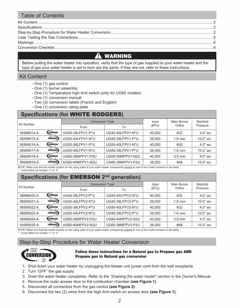
Step-by-Step Procedure for Water Heater Conversion
1. Shut down your water heater by unplugging the blower unit power cord from the wall receptacle.2. Turn “OFF” the gas supply. 3. Drain the water heater completely. Refer to the “Draining the water heater” section in the Owner’s Manual.4. Remove the outer access door to the combustion chamber (see Figure 1).5. Disconnect all connectors from the gas control (see Figure 2).6. Disconnect the two (2) wires from the high limit switch on access door (see Figure 1).
Kit Content - One (1) gas control - One (1) burner assembly - One (1) Temperature high limit switch (only for UG60 models) - One (1) conversion manual - Two (2) conversion labels (French and English) - One (1) conversion rating plate
Kit Content ................................................................................................................................................................... 2Specifications .............................................................................................................................................................. 2Step-by-Step Procedure for Water Heater Conversion ............................................................................................... 2Leak Testing the Gas Connections ............................................................................................................................. 5Markings ...................................................................................................................................................................... 6Conversion Checklist ................................................................................................................................................... 6
Before putting the water heater into operation, verify that the type of gas supplied to your water heater and the type of gas your water heater is set to burn are the same. If they are not, refer to these instructions.
WARNING
Specifications (for WHITE RODGERS)
Specifications (for EMERSON 2nd generation)
Table of Contents
Follow these instructions for a Natural gas to Propane gas AND Propane gas to Natural gas conversion
Kit NumberConversion Type Input
(BTU)Main Burner
OrificeManifoldPressure From To
06999014-A UG40-38LFPV1-P*U UG40-40LFPV1-N*U 40,000 #32 4.0” wc
06999015-A UG40-40LFPV1-N*U UG40-38LFPV1-P*U 38,000 1.8 mm 10.0” wc
06999016-A UG50-38LFPV1-P*U UG50-40LFPV1-N*U 40,000 #32 4.0” wc
06999017-A UG50-40LFPV1-N*U UG50-38LFPV1-P*U 38,000 1.8 mm 10.0” wc
06999018-A UG60-38MFPV1-P2U UG60-40MFPV1-N2U 40,000 3.0 mm 4.0” wc
06999019-A UG60-40MFPV1-N2U UG60-38MFPV1-P2U 38,000 #48 10.0” wc
Kit NumberConversion Type Input
(BTU)Main Burner
OrificeManifoldPressure From To
06999020-A UG40-38LFPV2-P*U UG40-40LFPV2-N*U 40,000 #32 4.0” wc
06999021-A UG40-40LFPV2-N*U UG40-38LFPV2-P*U 38,000 1.8 mm 10.0” wc
06999022-A UG50-38LFPV2-P*U UG50-40LFPV2-N*U 40,000 #32 4.0” wc
06999023-A UG50-40LFPV2-N*U UG50-38LFPV2-P*U 38,000 1.8 mm 10.0” wc
06999024-A UG60-38MFPV2-P2U UG60-40MFPV2-N2U 40,000 3.0 mm 4.0” wc
06999025-A UG60-40MFPV2-N2U UG60-38MFPV2-P2U 38,000 #48 10.0” wc
NOTE: Make sure that the model number on the rating plate of your water heater corresponds exactly to one of the model numbers in the table.* : Could either be number “1” or “2”
NOTE: Make sure that the model number on the rating plate of your water heater corresponds exactly to one of the model numbers in the table.* : Could either be number “1” or “2”

3
Figure 1
7. Disconnect the two (2) wires from the ignitor assembly to the flammable vapor sensor by removing the protective cover and the flammable vapor sensor (see Figures 1 and 3).8. Remove the right portion of the inner access door to the combustion chamber by: A - Removing the two (2) screws on the right side of the door. B - Removing the two (2) screws joining the two (2) access doors together (see Figure 1).9. Remove the left portion of the inner access door to the combustion chamber by removing the two (2) screws on the left side of the door (see Figure 1).10. Unscrew the gas manifold fitting from the gas control (see Figure 2).11. Remove the burner assembly from the combustion chamber.
Figure 2
FlammableVapor Sensor
Protective Cover
OuterAccess Door
Right PortionInner Access Door
Screws
Gasket
MainBurnerOrifice
Burner
Gas Manifold Fitting
GasManifoldTube
Connectors to FlammableVapor Sensor
Connectors toFlammableVapor Sensor
Connecteurs au détecteurde vapeursinflammables
Connecteurs audétecteurde vapeursinflammables
Baguedu conduit de gaz
Baguedu conduitde gaz
MainBurnerOrifice
IgnitorAssembly
MainWiring
HarnessConnector
IgnitorAssembly
WireConnector
GasManifoldFitting
Left PortionInner Access Door
Détecteur de vapeursinflammables
Couvercleprotecteur
Orificeprincipal
du brûleur
Orificeprincipal
du brûleur
Brûleur
Brûleur
Assemblagede l’allumeur
Assemblagede l’allumeur
Connecteurdu filageprincipal
Connecteurdu filageprincipal
Connecteurdu filage de
l’assemblagede l’allumeur
Connecteurdu filage de
l’assemblagede l’allumeur
Bague duconduitde gaz
Bague du conduit de gaz
Partie gauche - Porte d’accès interne
Partie droite - Porte d’accès interne
Ported’accès externe
Burner
IgnitorAssembly
Gas ManifoldFitting
Connectorsto control
Connecteursau contrôle
Connector to control
Connecteur au contrôle
GasManifoldTube
Conduitde gaz
Conduitde gaz
Main WiringHarness
Connector
Ignitor AssemblyWire Connector
Gas ManifoldFitting
FV SensorConnector
WHITE RODGERSIntelli-Vent
Gas Control
ON/OFFMain Switch
InterrupteurON/OFF
SerialNumberDate Code
Node SérieCode de date
Vis
Joint d’étanchéité
Contrôle au gazWHITE RODGERS
Intelli-Vent
Contrôle au gazEMERSON
2e génération
Brûleur pour White RodgersIntelli-Vent
Brûleur pourEMERSON 2e génération
EMERSON2nd generationGas Control
Burner for White RodgersIntelli-Vent
Burner for EMERSON2nd generation
Interrupteurhaute température
High limit switch
Connecteur dudétecteur de vapeursinflammables

12. Unscrew the natural gas control and replace it with the propane gas control supplied in the conversion kit (see Figure 1).
13. For UG60-40MFPV1-N2U only (Kit No 06999019-A) or UG60-40MFPV2-N2U only (Kit No 06999025-A),
Replace high temperature limit switch set at 270˚F (132˚C) located on the right portion of the inner access door by the high temperature limit switch set at 240˚F (115˚C) supplied in the kit (see Figure 1).
14. Put the propane gas burner assembly, supplied in the kit, back into the combustion chamber ensuring that the flat end of the manifold tube is inserted in the slot of the manifold bracket welded in the combustion chamber.
15. Screw the gas manifold fitting into the gas control (see Figure 2).
16. Inspect the gasket on the interior side of the inner access doors for damage. If damaged, replace the inner access door(s) (see Figure 1).
17. Install the left portion of the inner access door to the combustion chamber (see Figure 1).
18. Install the right portion of the inner access door to the combustion chamber (see Figure 1).
19. Connect all connectors back to the gas control (see Figure 2).
4
12. Unscrew the propane gas control and replace it with the natural gas control supplied in the conver-sion kit (see Figure 1).
13. For UG60-38MFPV1-P2U only (Kit No 06999018-A) or UG60-38MFPV2-P2U only (Kit No 06999024-A), Replace high temperature limit switch set at 240˚F (115˚C) located on the right portion of the inner access door by the high temperature limit switch set at 270˚F (132˚C) supplied in the kit (see Figure 1).
14. Put the natural gas burner assembly, supplied in the kit, back into the combustion chamber ensur-ing that the flat end of the manifold tube is inserted in the slot of the manifold bracket welded in the combustion chamber.
Figure 3
Follow these instructions for a Natural gas to Propane gas conversion
(Kit No. 06999015-A, 06999017-A, and 06999019-A for PV1 models and
Kit No. 06999021-A, 06999023-A, and 06999025-Afor PV2 models)
Follow these instructions for a Propane gas to Natural gas conversion
(Kit No. 06999014-A, 06999016-A and 06999018-A for PV1 models and
Kit No. 06999020-A, 06999022-A and 06999024-A for PV2 models)
FlammableVapor Sensor
Protective Cover
OuterAccess Door
Right PortionInner Access Door
Screws
Gasket
MainBurnerOrifice
Burner
Gas Manifold Fitting
GasManifoldTube
Connectors to FlammableVapor Sensor
Connectors toFlammableVapor Sensor
Connecteurs au détecteurde vapeursinflammables
Connecteurs audétecteurde vapeursinflammables
Baguedu conduit de gaz
Baguedu conduitde gaz
MainBurnerOrifice
IgnitorAssembly
MainWiring
HarnessConnector
IgnitorAssembly
WireConnector
GasManifoldFitting
Left PortionInner Access Door
Détecteur de vapeursinflammables
Couvercleprotecteur
Orificeprincipal
du brûleur
Orificeprincipal
du brûleur
Brûleur
Brûleur
Assemblagede l’allumeur
Assemblagede l’allumeur
Connecteurdu filageprincipal
Connecteurdu filageprincipal
Connecteurdu filage de
l’assemblagede l’allumeur
Connecteurdu filage de
l’assemblagede l’allumeur
Bague duconduitde gaz
Bague du conduit de gaz
Partie gauche - Porte d’accès interne
Partie droite - Porte d’accès interne
Ported’accès externe
Burner
IgnitorAssembly
Gas ManifoldFitting
Connectorsto control
Connecteursau contrôle
Connector to control
Connecteur au contrôle
GasManifoldTube
Conduitde gaz
Conduitde gaz
Main WiringHarness
Connector
Ignitor AssemblyWire Connector
Gas ManifoldFitting
FV SensorConnector
WHITE RODGERSIntelli-Vent
Gas Control
ON/OFFMain Switch
InterrupteurON/OFF
SerialNumberDate Code
Node SérieCode de date
Vis
Joint d’étanchéité
Contrôle au gazWHITE RODGERS
Intelli-Vent
Contrôle au gazEMERSON
2e génération
Brûleur pour White RodgersIntelli-Vent
Brûleur pourEMERSON 2e génération
EMERSON2nd generationGas Control
Burner for White RodgersIntelli-Vent
Burner for EMERSON2nd generation
Interrupteurhaute température
High limit switch
Connecteur dudétecteur de vapeursinflammables
Follow these instructions for a Natural gas to Propane gas AND Propane gas to Natural gas conversion

20. Connect the two (2) wires to the high limit switch on the access door (see Figure 1).
21. Connect the two (2) wires from the ignitor assembly to the flammable vapor sensor and re-install the flammable vapor sensor and protective cover (see Figures 1 and 3).
22. Install the outer access door to the combustion chamber (see Figure 1).
23. Transcribe the serial number and the date code from the rating plate on your water heater to the rating plate supplied in the conversion kit (see Figure 4).
24. Apply this new rating plate OVER the original one on the water heater.
25. Attach the conversion label to the outside of the water heater near the rating plate. The label should be filled out and signed by a qualified installer or service organization (see Figure 5).
26. Fill the water heater with water.
27. Keep the unused parts for possible future conversions.
28. It is highly recommended that a combustion analysis be taken and that firing rate be checked to make sure that the water heater is operating safely.
5
FlammableVapor Sensor
Protective Cover
OuterAccess Door
Right PortionInner Access Door
Screws
Gasket
MainBurnerOrifice
Burner
Gas Manifold Fitting
GasManifoldTube
Connectors to FlammableVapor Sensor
Connectors toFlammableVapor Sensor
Connecteurs au détecteurde vapeursinflammables
Connecteurs audétecteurde vapeursinflammables
Baguedu conduit de gaz
Baguedu conduitde gaz
MainBurnerOrifice
IgnitorAssembly
MainWiring
HarnessConnector
IgnitorAssembly
WireConnector
GasManifoldFitting
Left PortionInner Access Door
Détecteur de vapeursinflammables
Couvercleprotecteur
Orificeprincipal
du brûleur
Orificeprincipal
du brûleur
Brûleur
Brûleur
Assemblagede l’allumeur
Assemblagede l’allumeur
Connecteurdu filageprincipal
Connecteurdu filageprincipal
Connecteurdu filage de
l’assemblagede l’allumeur
Connecteurdu filage de
l’assemblagede l’allumeur
Bague duconduitde gaz
Bague du conduit de gaz
Partie gauche - Porte d’accès interne
Partie droite - Porte d’accès interne
Ported’accès externe
Burner
IgnitorAssembly
Gas ManifoldFitting
Connectorsto control
Connecteursau contrôle
Connector to control
Connecteur au contrôle
GasManifoldTube
Conduitde gaz
Conduitde gaz
Main WiringHarness
Connector
Ignitor AssemblyWire Connector
Gas ManifoldFitting
FV SensorConnector
WHITE RODGERSIntelli-Vent
Gas Control
ON/OFFMain Switch
InterrupteurON/OFF
SerialNumberDate Code
Node SérieCode de date
Vis
Joint d’étanchéité
Contrôle au gazWHITE RODGERS
Intelli-Vent
Contrôle au gazEMERSON
2e génération
Brûleur pour White RodgersIntelli-Vent
Brûleur pourEMERSON 2e génération
EMERSON2nd generationGas Control
Burner for White RodgersIntelli-Vent
Burner for EMERSON2nd generation
Interrupteurhaute température
High limit switch
Connecteur dudétecteur de vapeursinflammables
Figure 4
Leak Testing the Gas Connections
You MUST leak test the gas connections before placing the water heater in operation.
- Light the water heater as outlined in the Owner’s Manual.
- Using a soap and water solution or leak-test solution, test all of the gas connections to the gas control by spraying the solution on them. The appearance of bubbles means that there is a leak. If this occurs, tighten the connection and re-test. Please, make sure not to wet the wires of the ignitor.
6
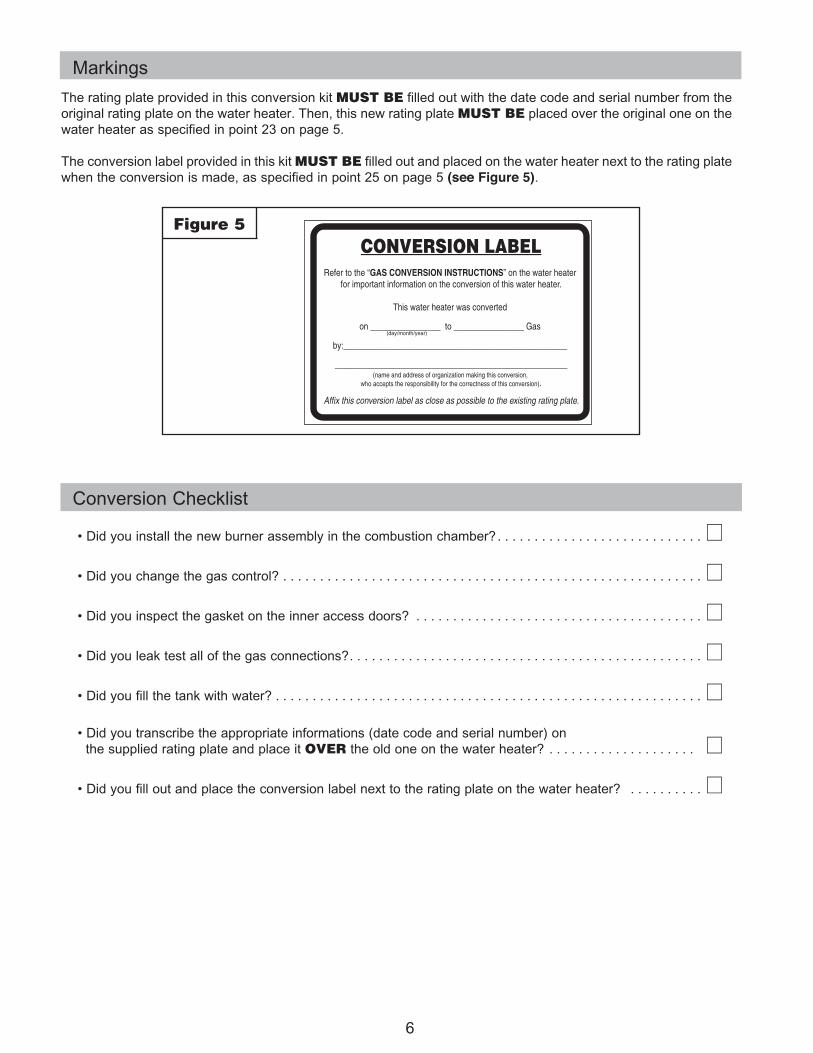
Figure 5
Markings
The rating plate provided in this conversion kit MUST BE filled out with the date code and serial number from the original rating plate on the water heater. Then, this new rating plate MUST BE placed over the original one on the water heater as specified in point 23 on page 5.
The conversion label provided in this kit MUST BE filled out and placed on the water heater next to the rating plate when the conversion is made, as specified in point 25 on page 5 (see Figure 5).
Conversion Checklist
•Didyouinstallthenewburnerassemblyinthecombustionchamber? . . . . . . . . . . . . . . . . . . . . . . . . . . . . L
•Didyouchangethegascontrol? . . . . . . . . . . . . . . . . . . . . . . . . . . . . . . . . . . . . . . . . . . . . . . . . . . . . . . . . . L
•Didyouinspectthegasketontheinneraccessdoors? . . . . . . . . . . . . . . . . . . . . . . . . . . . . . . . . . . . . . . . L
•Didyouleaktestallofthegasconnections? . . . . . . . . . . . . . . . . . . . . . . . . . . . . . . . . . . . . . . . . . . . . . . . . L
•Didyoufillthetankwithwater? . . . . . . . . . . . . . . . . . . . . . . . . . . . . . . . . . . . . . . . . . . . . . . . . . . . . . . . . . . L
•Didyoutranscribetheappropriateinformations(datecodeandserialnumber)on the supplied rating plate and place it OVERtheoldoneonthewaterheater? . . . . . . . . . . . . . . . . . . . . L
•Didyoufilloutandplacetheconversionlabelnexttotheratingplateonthewaterheater? . . . . . . . . . . L