Embed Size (px)
Citation preview

Tuesday 14 June 2016, 14:00 Session 18-4 J. Hartvigsen, L. Frost, S. Elangovan, J. Elwell
P. Dimick (IntraMicron)
NETL Award DE-FE0023863, PM Anthony Zinn
Conversion of Coal and Biomass to Liquid Hydrocarbons Using Gasification and a Hybrid
Fischer Tropsch Catalyst

CBTL Process-Program Connectivity
Coal-Biomass Gasifier
Technology development
System Demonstration Scope

Project Goals and Objectives • Jet fuel (Jet-A or JP-8 MIL-DTL-83133) • Capable eventually of 1000’s of gallons of jet fuel • Team led by Ceramatec
– Team members: • Ceramatec – Project lead and FT • IntraMicron – Sulfur removal and catalyst support • Chevron – Hybrid catalyst developer • EERC – Gasifier partner
– Demonstrate using 2 BPD pilot – Provide fuel for evaluation by USAF – Plant will produce over 1000 gallons per month – Provide design basis for 100 BPD module

Ceramatec FT System Strategy • Scale, Scope & Cost
– Small 0.1% to 10% of “World Scale” GTL
– Product syncrude with minimal upgrading
– CAPEX << $100k/bbl/day • Shop fabrication
– Reduce cost versus site built plants – Transportability to site (size limits on
road transport) – Quality control and mass production vs.
traditional economies of scale
• Catalyst loading and transport – Catalyst servicing done in shop – Replaceable reactor elements – Catalyst reduced and ready to
operate • Minimum infrastructure required • Take advantage of a variety of small
distributed resources – Biomass, biogas, coal-biomass
blend – Stranded gas, associated gas – CO2 co-electrolysis as intermittent
renewable energy storage

Small FT with Large Reactor Tubes?

MFEC Reactor Temperature Profile

0 0.5 1 1.5 2 2.5 3 3.5 4
0
200
400
600
800
1000
1200
0 0.05 0.1 0.15 0.2 0.25 0.3
Re in MFEC
Inis
de W
all H
eat T
rans
fer
Coe
ffici
ent
(W/m
2-kK
)
Face Velocity (m/s)
Cu_MFEC Cu_Packed Bed Al2O3_Packed Bed
Steam Condensing: 1000-3000 W/m2-K
Force Air Convection:10-200 W/m2-K
IntraMicron Fischer Tropsch Synthesis MFEC MFEC-Based GTLby Fischer-Tropsch
Synthesis
Natural Gas Fuel (Gasoline, Kerosene, Diesel)Traditional FTS Issues
• Lack of efficient heat transfer• Highly exothermic reaction• Prone to hot spots, runaway, and high temperature
catalyst deactivation• Selectivity is temperature dependent• Low per pass conversions necessary to mitigate
severe temperature rises • High capital plant costs
MFEC Benefits• High heat transfer rates• High mass transfer rates • High volumetric reaction rates• Near isothermal temperature profiles • Easy to fabricate and operate• Robust
0
10
20
30
40
50
0 0.1 0.2 0.3
EffectiveRadialThe
rmalCon
ductivity
W/m
-K
FaceVelocity(m/s)
CuMFECCatalystBed
TypicalPackedCatalystBed(0.17-0.21w/m-K)
50- to 200x bed thermal conductivity

IntraMicron Microfibrous Entrapped Catalyst (MFEC)
MFEC
MFECs consist of catalyst particles immobilized in media made of sinter-locked networks of micron-sized fibers. The fibers range from 2 to 25 µm, and the entrapped particles typically
range from 40 to 300 µm. The micron-sized fibers dominate the flow pattern, especially at low Reynolds numbers, significantly enhancing mass and heat transfer characteristics.
Microfibrous Matrix(1) Uniform velocity
profile (2) No channeling (3) High thermal
conductivity (M)(4) Better wall contacting (5) Fast heat transfer (M)(6) Near isothermal
temperature profile (M)
(M) Metal Microfibrous media only
Small Catalyst/ Adsorbent Particulates
(1) High external surface area
(2) Reduced intraparticle diffusion resistance
(3) Fast mass transfer(4) Improved selectivity
to large molecules
Microfibrous Entrapment(1) Frozen fluidized bed(2) Uniform particle
distribution(3) Random reactor
orientation(4) No further particle –
product separation Typical Packed
BedMFEC Bed

IntraMicron MFEC Preparation
Preformed MFM Sheets
ready to accept catalyst
Disc Formation Catalyst Entrapment
MFEC Preparation using wet lay techniques
MFM SinteringMFEC Assembled onto
Tree for Reactor Loading
Barrier Layer (bottom)
Catalyst Layer(top)
The composition of MFEC is tailored to provide the appropriate balance of heat and mass transfer for the target reaction. This included the fiber blend and entrapped catalyst size. MFEC typically contains 5 – 25 volume percent fibers and 5 to 30 volume percent catalyst.

Hot spots near center
Cold spots near wall
Parabolic fin
Ceramatec Alternative Thermal Structure • Geometric optimization FE thermal model
– Higher average temperature • Production and thermal risk
– Lower average temperature • Production and thermal risk
Thickness Position
WidthThickness
Aluminum extrusion reactor insertfor thermal management

IntraMicron Desulfurization Technology Suite (IM-DTS) IntraMicron’s Scalable Desulfurization Technology Suite is a synergistic combination of an oxidative sulfur removal (OSR) Catalyst, a desulfurization sorbent (regenerable or disposable), and a bed life sensor that enables efficient sulfur removal from distributed energy resources.
OSR Reactor H2S + 0.5 O2 à H2O + S
RSH + 0.5 O2 à R-OH +S
Adsorbent Bed Regenerable
or Disposable
S-laden Gas Low-S Gas (< 5ppm)
S-free Gas (< 0.1 ppm)
Sulfur Condensation
Elemental Sulfur
Bed Life Sensor
Optical Signal
Oxidizer (Typically Air)
Patent Pending
Patent Pending Patents Issued and Pending
• OSR converts majority of H2S to elemental sulfur without significant SO2 production
• BLS optimizes adsorbent utilization to minimize waste
• Process easily accommodates varying sulfur levels and outlet thresholds
• Up to 75% cost reduction compared to current state of the art technologies

Ceramatec 100mm NPS FT Pre-Pilot Facility • Plasma reformer • Syngas compression • Syngas drying • Syngas storage • Modular reactor • Validate advanced FT
cooling structures in 100mm NPS reactor
Fresh SyngasF
Coriolis-11
FCV-11
PV-11
Cool DownTank A
HX-2
RC-31
PV-12
Cool DownTank B
HX-1
FCoriolis-12
FCV-12
Condenser
P-22
PRV-21
Recycle Syngas
E-13
Heated Tank A Heated Tank B
PV-14
PV-13
PV-15
ProductStorage Tank
Cool to 130 deg C
PRV-11
Water Vapor Drum
FCV-13
FCo
riolis
-13
PRV-12Pulse dampers
HB-11
PV-16
PP P
P
PRV-13BPR-11PRV-14
BPR-12
SPR-11
To flare To flare
½”
P-21 YS-21Drain
DFM-31 GV-31
P
GV-22
H2/N2 Line
Ht-21
Ht-31
PT-21 BPR-21
PT-13
DFM-23
PG-11PG-12 PG-14
PG-13
LS-11
RF-31P-31
Coolant Reservoir
CV-21CV-22
3/8"
Product
Finned Tubes
Finned Tubes
Fan
RecycleSyngas
Cold Trap
Hot Trap
Flare line
Coolant loop
Therminol Tank
Therminol Pump
P
To flare
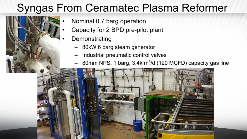
Syngas From Ceramatec Plasma Reformer • Nominal 0.7 barg operation • Capacity for 2 BPD pre-pilot plant • Demonstrating
– 80kW 6 barg steam generator – Industrial pneumatic control valves – 80mm NPS, 1 barg, 3.4k m3/d (120 MCFD) capacity gas line

Syngas Compressor for 2 bbl/day Commissioning

Ceramatec Syngas Storage Facility 2 x 2000 liter, 55 bar storage tanks
10-14 bar Intermediate storage
Compressor

Single Tube 100mm NPS FT Reactor Test Bed System

FT Product Collection
Draining Product
Product Collection Scales, kg

Wax Free Product Hybrid Co as Trilobe, w/Fin

Wax Free Product Hybrid Co in MFEC

MFEC Chevron Hybrid Co Catalyst Product Distribution
0"
5"
10"
15"
20"
25"
0" 5" 10" 15" 20" 25" 30" 35"
Weight%
(
Carbon(Chain(Length(
((
033115"
040215"
040315"
040515"
051015"
051115"
051215"

Ceramatec 100mm FT Runs Q1-Q2 2015 • FT operations March 19 to June 01 2015
• 74 Calendar Days • 54 Operating Days (nominal 1296 hours) • 2 catalyst regeneration cycles
• Product collection – 45 sample collection periods – 375 kg (136 gal) FT oil collected and stored
• Carbon number distribution by SimDis GC – 920 kg FT produced water
• Treated, tested, discharged • Production rate
– Varying syngas composition, pressure, reactor temperature • 19.3 liters/day peak rate • 14.7 liters/day sustained over 12 day period • 9.6 liters/day average including startup

Selectivity & Productivity Extrudate-Fin • 23 Dec 2014
– 1.25 kg hybrid Co trilobe – 240°C reactor – 20 bar exit – 3.22 SCFM syngas
• 35% N2, 40% H2, 19% CO – 8 SCFM recycle – 92% H2 conversion – 86% CO conversion – 23.3% CH4 selectivity – 3.4% CO2 selectivity – 0.197 gC5+/g-cat/hr
• 16 Oct 2014 – 1.25 kg hybrid Co trilobe – 250°C reactor – 20 bar exit – 4.59 SCFM syngas
• 52% N2, 29% H2, 14% CO
– 10 SCFM recycle – 79% H2 conversion – 71% CO conversion – 32.5% CH4 selectivity – 2.6% CO2 selectivity – 0.091 gC5+/g-cat/hr

Selectivity & Productivity MFEC • 05 April 2015
– 2kg hybrid Co in MFEC – 240°C reactor – 20 bar exit – 5.88 SCFM syngas
• 26% N2, 45% H2, 22% CO – 10 SCFM recycle – 78% H2 conversion – 78% CO conversion – 18.8% CH4 selectivity – 0% CO2 selectivity – 0.359 gC5+/g-cat/hr
• 12 May 2015 – 2kg hybrid Co in MFEC – 220°C reactor – 20 bar exit – 4.64 SCFM syngas
• 23% N2, 48% H2, 24% CO – 8 SCFM recycle – 52% H2 conversion – 51% CO conversion – 15.3% CH4 selectivity – 0% CO2 selectivity – 0.185 gC5+/g-cat/hr

Ceramatec Reactor Loading at IntraMicron
Ceramatec 100mm NPS, 7-tube, 2 bbl/day FT reactor
Reactor tube sheet FunnelMFEC
Rollers
Loading a Reactor Tube With Intramicron MFEC

Ceramatec 2 bbl/d 100mm NPS FT Plant Layout
Construction Planned Summer 2016, Commissioning Fall 2016
Status & Summary • Ceramatec 100mm NPS, FT reactor demonstrated
– Tested with various catalysts (conventional Co & Fe, hybrid Co) – Heat removal with aluminum fin insert and with Cu MFEC
• Fabricating 2 BPD – 100mm NPS, 7-tube reactor – Initial testing will use reformed natural gas – Coal / biomas testing planned at EERC
• Designs and costing on larger facilities – 1 MMSCFD (28.3k m3/day) plasma reformers for GTL (Built for NH3 plant) – 10 BPD pilot designed and costed – 100 BPD FT reactor module planned – Costing on ~2000 BPD GTL plant performed by commercial partner

Energy Storage Via Electrolytic Synfuel
Gen IV Nuclear
Wind CO2 Electrolysis to FT Synfuels
Advanced Concentrator PV

Acknowledgements / Contact
• The 2 BPD CTL / BTL system is being funded by the USAF with management by US DOE NETL
• The Laboratory GTL system was partially funded by State of Wyoming, Office of Naval Research, US Department of Energy, Ceramatec, and other commercial entities
• Some of the carbon distribution data was from catalysts provided by third parties
For further information contact: Lyman Frost [email protected] 801 956 – 1039 (office) 801 910 – 1346 (cell)