Embed Size (px)
Citation preview
1
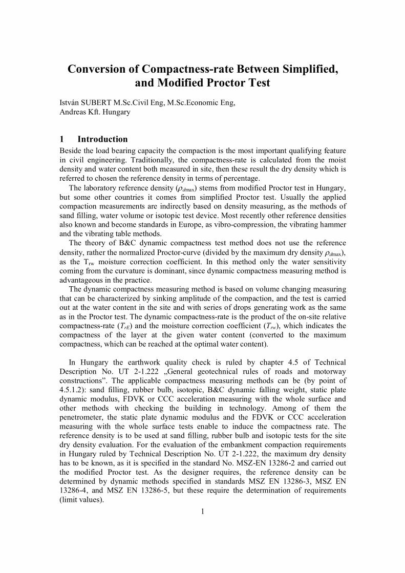
Conversion of Compactness-rate Between Simplified, and Modified Proctor Test
István SUBERT M.Sc.Civil Eng, M.Sc.Economic Eng, Andreas Kft. Hungary
1 Introduction Beside the load bearing capacity the compaction is the most important qualifying feature in civil engineering. Traditionally, the compactness-rate is calculated from the moist density and water content both measured in site, then these result the dry density which is referred to chosen the reference density in terms of percentage.
The laboratory reference density (dmax) stems from modified Proctor test in Hungary, but some other countries it comes from simplified Proctor test. Usually the applied compaction measurements are indirectly based on density measuring, as the methods of sand filling, water volume or isotopic test device. Most recently other reference densities also known and become standards in Europe, as vibro-compression, the vibrating hammer and the vibrating table methods.
The theory of B&C dynamic compactness test method does not use the reference density, rather the normalized Proctor-curve (divided by the maximum dry density dmax), as the Trw moisture correction coefficient. In this method only the water sensitivity coming from the curvature is dominant, since dynamic compactness measuring method is advantageous in the practice.
The dynamic compactness measuring method is based on volume changing measuring that can be characterized by sinking amplitude of the compaction, and the test is carried out at the water content in the site and with series of drops generating work as the same as in the Proctor test. The dynamic compactness-rate is the product of the on-site relative compactness-rate (TrE) and the moisture correction coefficient (Trw), which indicates the compactness of the layer at the given water content (converted to the maximum compactness, which can be reached at the optimal water content).
In Hungary the earthwork quality check is ruled by chapter 4.5 of Technical
Description No. UT 2-1.222 „General geotechnical rules of roads and motorway constructions”. The applicable compactness measuring methods can be (by point of 4.5.1.2): sand filling, rubber bulb, isotopic, B&C dynamic falling weight, static plate dynamic modulus, FDVK or CCC acceleration measuring with the whole surface and other methods with checking the building in technology. Among of them the penetrometer, the static plate dynamic modulus and the FDVK or CCC acceleration measuring with the whole surface tests enable to induce the compactness rate. The reference density is to be used at sand filling, rubber bulb and isotopic tests for the site dry density evaluation. For the evaluation of the embankment compaction requirements in Hungary ruled by Technical Description No. ÚT 2-1.222, the maximum dry density has to be known, as it is specified in the standard No. MSZ-EN 13286-2 and carried out the modified Proctor test. As the designer requires, the reference density can be determined by dynamic methods specified in standards MSZ EN 13286-3, MSZ EN 13286-4, and MSZ EN 13286-5, but these require the determination of requirements (limit values).
2
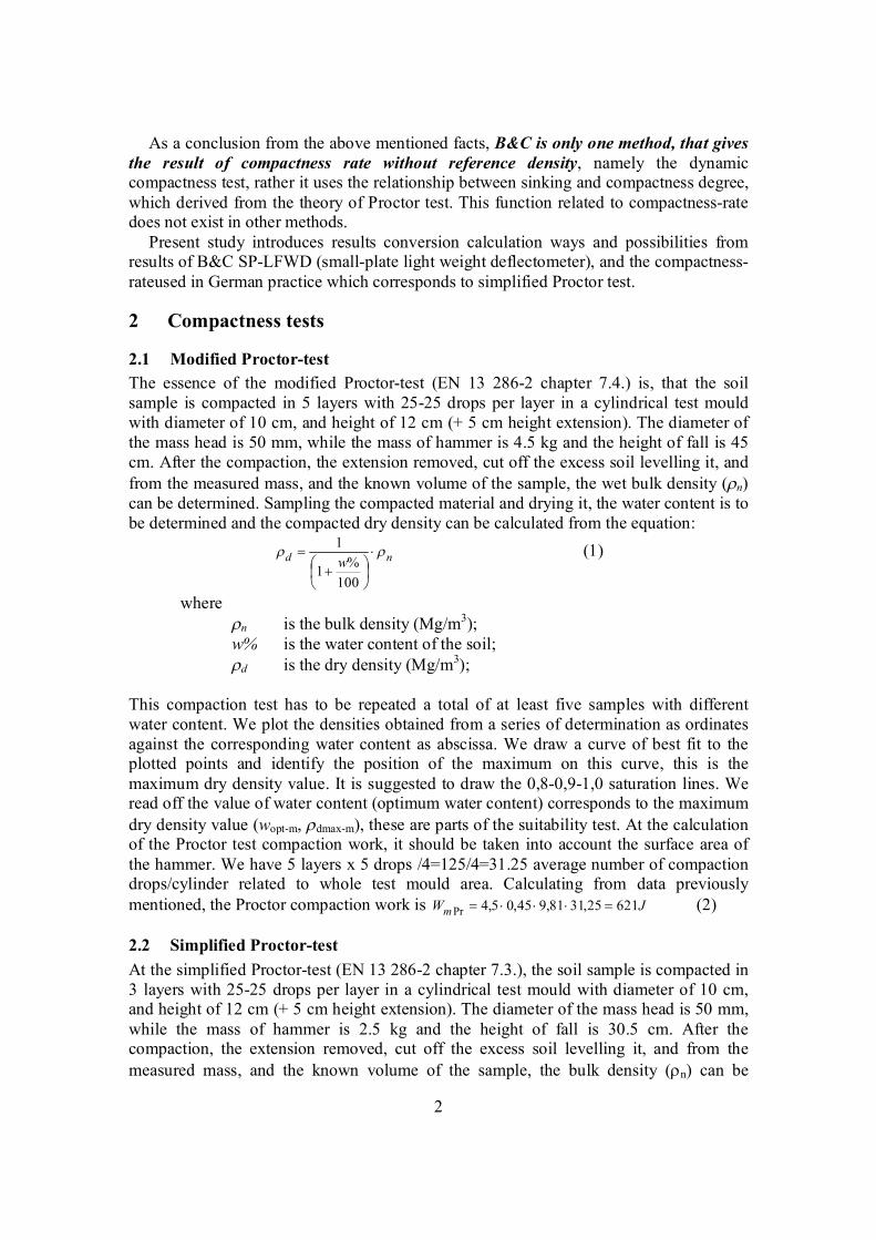
As a conclusion from the above mentioned facts, B&C is only one method, that gives the result of compactness rate without reference density, namely the dynamic compactness test, rather it uses the relationship between sinking and compactness degree, which derived from the theory of Proctor test. This function related to compactness-rate does not exist in other methods.
Present study introduces results conversion calculation ways and possibilities from results of B&C SP-LFWD (small-plate light weight deflectometer), and the compactness-rateused in German practice which corresponds to simplified Proctor test.
2 Compactness tests
2.1 Modified Proctor-test The essence of the modified Proctor-test (EN 13 286-2 chapter 7.4.) is, that the soil sample is compacted in 5 layers with 25-25 drops per layer in a cylindrical test mould with diameter of 10 cm, and height of 12 cm (+ 5 cm height extension). The diameter of the mass head is 50 mm, while the mass of hammer is 4.5 kg and the height of fall is 45 cm. After the compaction, the extension removed, cut off the excess soil levelling it, and from the measured mass, and the known volume of the sample, the wet bulk density (n) can be determined. Sampling the compacted material and drying it, the water content is to be determined and the compacted dry density can be calculated from the equation:
nd w
100%1
1 (1)
where n is the bulk density (Mg/m3); w% is the water content of the soil; d is the dry density (Mg/m3); This compaction test has to be repeated a total of at least five samples with different water content. We plot the densities obtained from a series of determination as ordinates against the corresponding water content as abscissa. We draw a curve of best fit to the plotted points and identify the position of the maximum on this curve, this is the maximum dry density value. It is suggested to draw the 0,8-0,9-1,0 saturation lines. We read off the value of water content (optimum water content) corresponds to the maximum dry density value (wopt-m, dmax-m), these are parts of the suitability test. At the calculation of the Proctor test compaction work, it should be taken into account the surface area of the hammer. We have 5 layers x 5 drops /4=125/4=31.25 average number of compaction drops/cylinder related to whole test mould area. Calculating from data previously mentioned, the Proctor compaction work is JWm 62125,3181,945,05,4Pr (2)
2.2 Simplified Proctor-test At the simplified Proctor-test (EN 13 286-2 chapter 7.3.), the soil sample is compacted in 3 layers with 25-25 drops per layer in a cylindrical test mould with diameter of 10 cm, and height of 12 cm (+ 5 cm height extension). The diameter of the mass head is 50 mm, while the mass of hammer is 2.5 kg and the height of fall is 30.5 cm. After the compaction, the extension removed, cut off the excess soil levelling it, and from the measured mass, and the known volume of the sample, the bulk density (n) can be
3
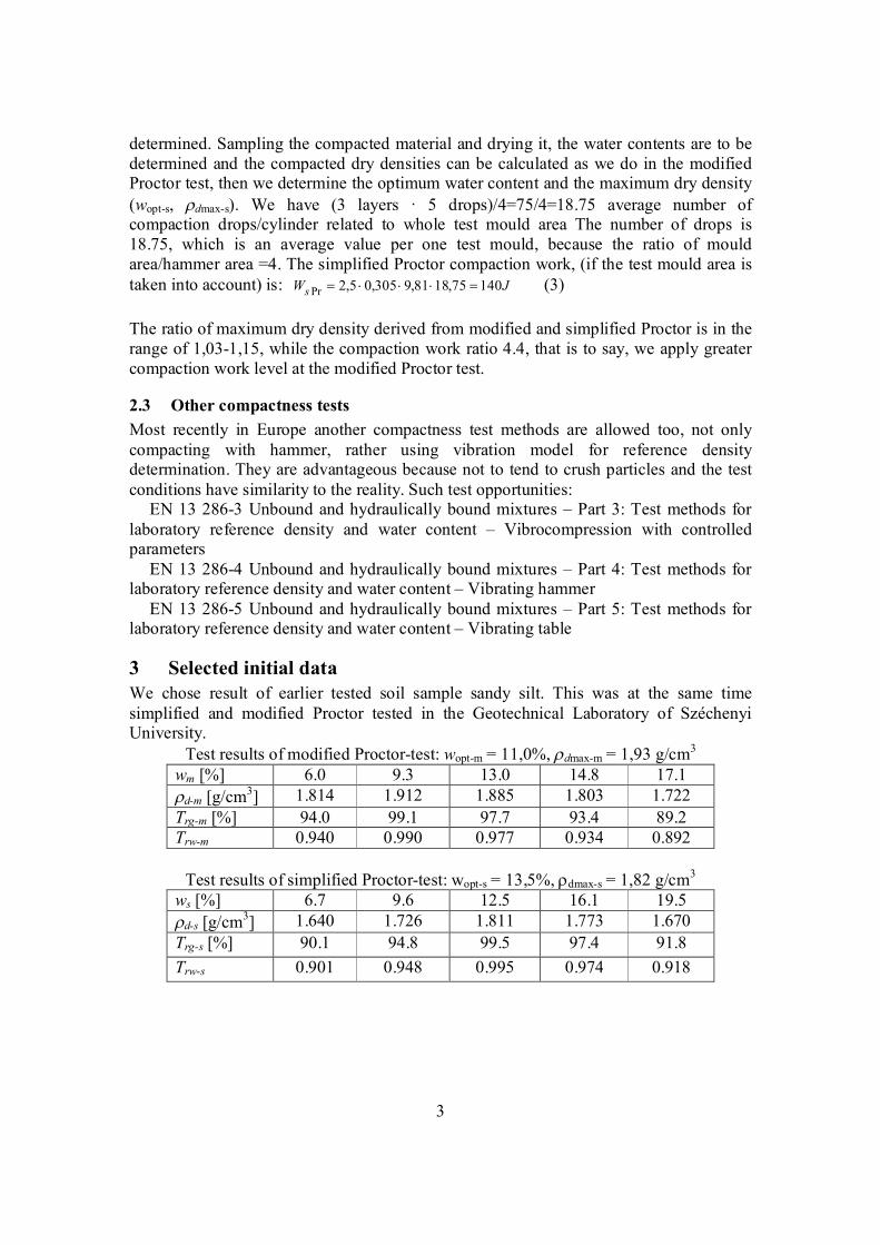
determined. Sampling the compacted material and drying it, the water contents are to be determined and the compacted dry densities can be calculated as we do in the modified Proctor test, then we determine the optimum water content and the maximum dry density (wopt-s, dmax-s). We have (3 layers · 5 drops)/4=75/4=18.75 average number of compaction drops/cylinder related to whole test mould area The number of drops is 18.75, which is an average value per one test mould, because the ratio of mould area/hammer area =4. The simplified Proctor compaction work, (if the test mould area is taken into account) is: JWs 14075,1881,9305,05,2Pr (3)
The ratio of maximum dry density derived from modified and simplified Proctor is in the range of 1,03-1,15, while the compaction work ratio 4.4, that is to say, we apply greater compaction work level at the modified Proctor test.
2.3 Other compactness tests Most recently in Europe another compactness test methods are allowed too, not only compacting with hammer, rather using vibration model for reference density determination. They are advantageous because not to tend to crush particles and the test conditions have similarity to the reality. Such test opportunities:
EN 13 286-3 Unbound and hydraulically bound mixtures – Part 3: Test methods for laboratory reference density and water content – Vibrocompression with controlled parameters
EN 13 286-4 Unbound and hydraulically bound mixtures – Part 4: Test methods for laboratory reference density and water content – Vibrating hammer
EN 13 286-5 Unbound and hydraulically bound mixtures – Part 5: Test methods for laboratory reference density and water content – Vibrating table
3 Selected initial data We chose result of earlier tested soil sample sandy silt. This was at the same time simplified and modified Proctor tested in the Geotechnical Laboratory of Széchenyi University.
Test results of modified Proctor-test: wopt-m = 11,0%, dmax-m = 1,93 g/cm3
wm [%] 6.0 9.3 13.0 14.8 17.1 d-m [g/cm3] 1.814 1.912 1.885 1.803 1.722 Trg-m [%] 94.0 99.1 97.7 93.4 89.2 Trw-m 0.940 0.990 0.977 0.934 0.892
Test results of simplified Proctor-test: wopt-s = 13,5%, dmax-s = 1,82 g/cm3
ws [%] 6.7 9.6 12.5 16.1 19.5 d-s [g/cm3] 1.640 1.726 1.811 1.773 1.670 Trg-s [%] 90.1 94.8 99.5 97.4 91.8 Trw-s 0.901 0.948 0.995 0.974 0.918
4
1.40
1.60
1.80
2.00
2.20
2.40
4 6 8 10 12 14 16 18 20 22
w %
szár
az
egyszerűsített módosított
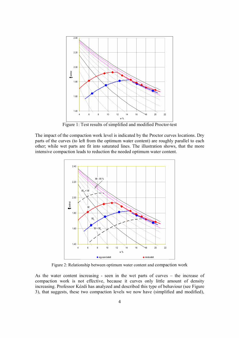
Figure 1: Test results of simplified and modified Proctor-test The impact of the compaction work level is indicated by the Proctor curves locations. Dry parts of the curves (to left from the optimum water content) are roughly parallel to each other; while wet parts are fit into saturated lines. The illustration shows, that the more intensive compaction leads to reduction the needed optimum water content.
Figure 2: Relationship between optimum water content and compaction work As the water content increasing - seen in the wet parts of curves – the increase of compaction work is not effective, because it curves only little amount of density increasing. Professor Kézdi has analyzed and described this type of behaviour (see Figure 3), that suggests, these two compaction levels we now have (simplified and modified),
1.40
1.60
1.80
2.00
2.20
2.40
4 6 8 10 12 14 16 18 20 22
w %
szár
az
egyszerűsített módosított
Ws
88 - 95 %
W
W < Ws
Wm < W
5
every time can expand and the upper limit of the expansion is only limited by the development of the compacting equipments. If we have larger compaction work in site comparing to apply in the laboratory, then the optimum water content will be less then we determined it in the laboratory. So the present simplified or modified compaction work only a chosen value or an agreement.
4. Conversion modified and simplified Proctor test results The B&C dynamic compactness and bearing capacity test method applies the same compaction work as the modified Proctor test, meanwhile, the countries using simplified Proctor tests are restricted in using this equipment without conversion calculation. There is no any hamper to make this conversion to allow using B&C equipment.
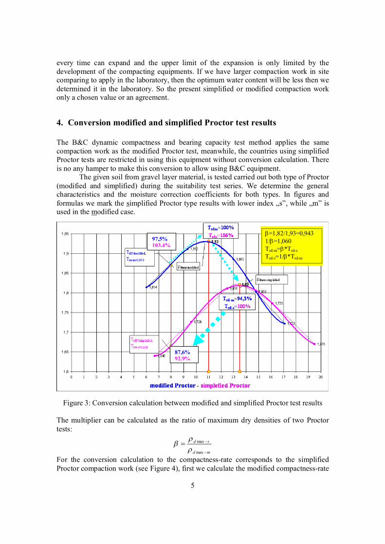
The given soil from gravel layer material, is tested carried out both type of Proctor (modified and simplified) during the suitability test series. We determine the general characteristics and the moisture correction coefficients for both types. In figures and formulas we mark the simplified Proctor type results with lower index „s”, while „m” is used in the modified case.
Figure 3: Conversion calculation between modified and simplified Proctor test results The multiplier can be calculated as the ratio of maximum dry densities of two Proctor tests:
md
sd
max
max
For the conversion calculation to the compactness-rate corresponds to the simplified Proctor compaction work (see Figure 4), first we calculate the modified compactness-rate
=1,82/1,93=0,943 1/=1,060 Trd-m=*Trd-s Trd-s=1/*Trd-m
87,6% 92,9%
97,5% 103,4%
6
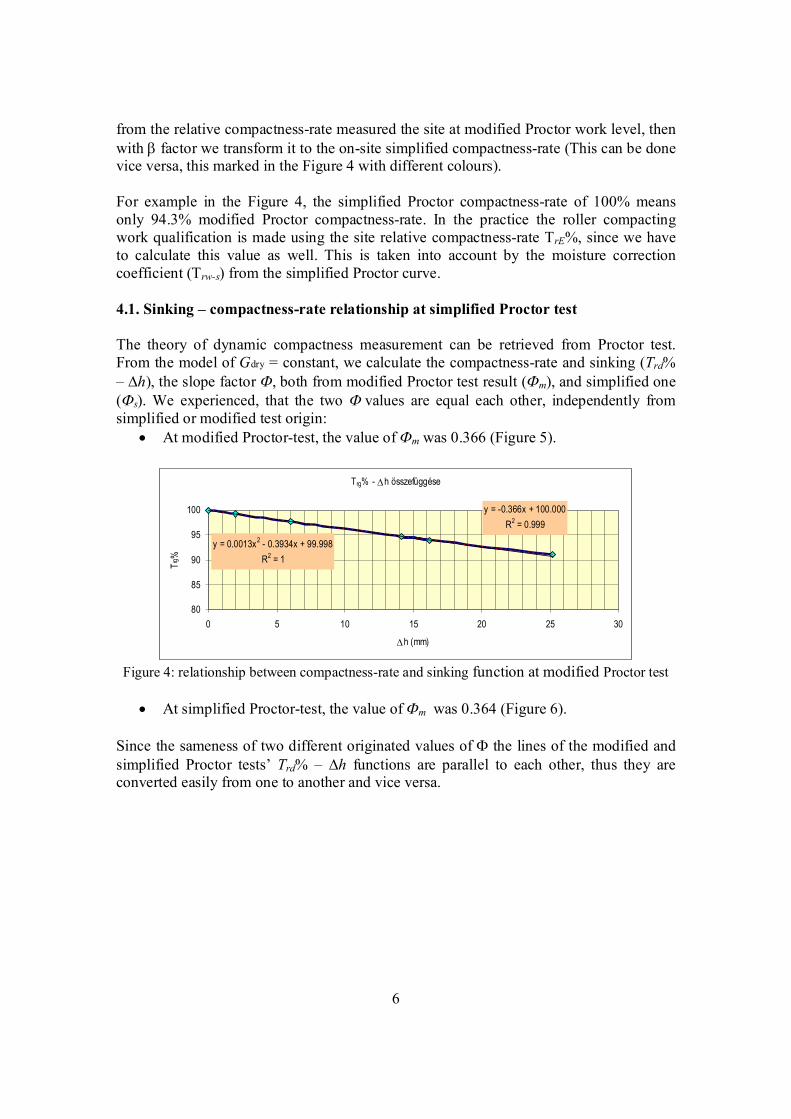
from the relative compactness-rate measured the site at modified Proctor work level, then with factor we transform it to the on-site simplified compactness-rate (This can be done vice versa, this marked in the Figure 4 with different colours). For example in the Figure 4, the simplified Proctor compactness-rate of 100% means only 94.3% modified Proctor compactness-rate. In the practice the roller compacting work qualification is made using the site relative compactness-rate TrE%, since we have to calculate this value as well. This is taken into account by the moisture correction coefficient (Trw-s) from the simplified Proctor curve. 4.1. Sinking – compactness-rate relationship at simplified Proctor test The theory of dynamic compactness measurement can be retrieved from Proctor test. From the model of Gdry = constant, we calculate the compactness-rate and sinking (Trd% – h), the slope factor , both from modified Proctor test result (m), and simplified one (s). We experienced, that the two values are equal each other, independently from simplified or modified test origin:
At modified Proctor-test, the value of mwas 0.366 (Figure 5).
Trg% -h összefüggése
y = -0.366x + 100.000R2 = 0.999
y = 0.0013x2 - 0.3934x + 99.998R2 = 1
80
85
90
95
100
0 5 10 15 20 25 30
h (mm)
Trg%
Figure 4: relationship between compactness-rate and sinking function at modified Proctor test
At simplified Proctor-test, the value of mwas 0.364 (Figure 6).
Since the sameness of two different originated values of the lines of the modified and simplified Proctor tests’ Trd% – h functions are parallel to each other, thus they are converted easily from one to another and vice versa.
7
Trg% -h összefüggése
y = -0.364x + 100.000R2 = 0.999
y = 0.0013x2 - 0.3934x + 99.998R2 = 1
80
85
90
95
100
0 5 10 15 20 25 30
h (mm)
Trg%
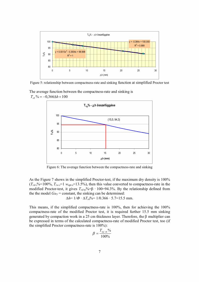
Figure 5: relationship between compactness-rate and sinking function at simplified Proctor test The average function between the compactness-rate and sinking is 100366,0% hTrE
Trg% - Dh összefüggése
80
85
90
95
100
0 5 10 15 20 25 30
Dh (mm)
Trg %
Figure 6: The average function between the compactness-rate and sinking
As the Figure 7 shows in the simplified Proctor-test, if the maximum dry density is 100% (Trd-s%=100%, Trw-s=1 wopt-s=13.5%), then this value converted to compactness-rate in the modified Proctor-test, it gives Trd-m%=·100=94.3%. By the relationship defined from the the model Gdry = constant, the sinking can be determined:
h= 1/ · Trd%= 1/0.366 · 5.7=15.5 mm. This means, if the simplified compactness-rate is 100%, then for achieving the 100% compactness-rate of the modified Proctor test, it is required further 15.5 mm sinking generated by compaction work in a 25 cm thickness layer. Therefore, the multiplier can be expressed in terms of the calculated compactness-rate of modified Proctor test, too (if the simplified Proctor compactness-rate is 100%):
%100%mrgT
(15,5; 94,3)
8
4.2 Example
Site results By this example, the dynamic compactness-rate is TrE-m% = 96.6% measured on site with B&C equipment, in the case of a silty-sand, the natural water content is wt = 9.6%, which means Trw-m = 0.996 moisture correction coefficient.
Calculation of compactness-rate complies with modified Proctor test The test result for the dynamic compactness-rate using the mrwmrEmrd TTT base formula %2.96996.0%6.96% mrdT Compactness-rate complies with simplified Proctor test In this case, the compactness-rate calculated by the simplified Proctor test is the following: %0.102%2.96943.0/1/1% mrdsrd TT . The optimum water content of the simplified Proctor is wopt-s = 13.5%. The natural water content is the same as previous wt = 9.6, this now means Trw-s = 0.948 moisture correction coefficient. It is known, that the simplified Proctor 100% compactness-rate corresponds only 94.3%, in the scale of the modified proctor test, that is why, if we have larger then 94.3% compactness-rate, then it exceeds the 100% compactness-rate in terms of simplified Proctor compactness-rate. So in the German practice sometimes the specification requires more then 100% compactness-rate. On-site relative compactness-rate complies with simplified Proctor test From the calculated compactness-rate of the simplified Proctor test, we can calculate the on site relative compactness-rate of simplified Proctor, using its own moisture correction coefficient of simplified Proctor:
srw
srdsrE T
TT
(%)
The on site relative simplified compactness-rate (Trw-s) measures the suitability of the roller compacting work at the measured natural water content, wt = 9.6%, determined from the curve of simplified Proctor, is the following: Trw-s=0.948, and as a conclusion of
it, %6.107948.0
0.102srET , therefore, at the given water content, the on site relative
compactness-rate is TrE-s= 108% in the case of compaction work complies with simplified Proctor test.
5 On site relative compactness-rate calculation using different compaction work
In the site, we determined the on site relative compactness-rate, at the natural water content, with dynamic method, which complies with the modified Proctor test compaction work, such a way, that we took the compactness state measured after the first drop, then after 18 drops we made compaction sinking curve, and from this curve we created deformation rate. From the residue sinking the compactness can be calculated
9
which is also known as on site relative compactness, and it is the accessible compactness at the given water content, in the best case it can reach up 100%. The relative compactness rate is calculated by the next formula:
mmmrE DT 100 , where Dm-m is the deformation index calculated with the modified Proctor work;
the slope of the line of the ΔVmm – Tr% function calculated from Gdry = constant model, ( = 0.365 ± 0.025).
At the modified Proctor compaction work the value of Dm is calculated with the weighted average below, from the sum of residue deformation. The total deformation hi, is the amount of flexible and residual deformations. The following formula shows the sinking increment (negative) calculation:
ihhs iii 1
)( 1 ….
Where hi-hi+1≥0, if hi-hi+1<0, then si=0
Thus the flexible deformation does not take part in the calculation. The sinking increment after every drop, is is a numeral derivation. This step can be expressed, as a numeral derivation at every drop. We estimate the total sinking so far with using the actual number of drops. This weighted average is named deformation index (Dm-m), and it can be calculated with the next generalized formula:
ji
iii
jmm hhjSD
11
17
1
))((*(17
where hi the total deformation (sum of flexible and residual one); i = 1 ... 18 and h1≥h2≥h3…… …h17≥h18
17/
)((*
..........)(17.......16
...)(3)(2
)(1
11
17
1
181743322117
1617322116
4332213
32212
211
SD
hhjS
hhhhhhhhShhhhhhS
hhhhhhShhhhS
hhS
mm
ji
iii
j
The previously described calculation method of the on site relative compactness, which complies with simplified Proctor work, can be made in another way. The other possibility could be, if we applied compaction work corresponding to simplified Proctor test, controlled the work by the number of drops. In this case, the compaction sinking curve only was made from 6 drops, and the deformation index was calculated from these.
10
This residue sinking curve, which creates “the simplified Proctor state”, is called on site relative simplified compactness, and this characterizes the maximum accessible compactness-rate at the given water content. This method has appreciable disadvantage, namely we could not measure compactness-rate of simplified Proctor test over the value of 100%, and hence the using of conversion calculating method is expected. The theory adaptation also enables to calculate on site relative compactness of simplified Proctor:
smsrE DT 100 ,
where Dm-s – deformation index.
The total deformation hi is the sum of flexible and residual deformations. The following formula shows the sinking increment (negative) calculation:
ihhs iii 1
)( 1 …
where hi-hi+1≥0 , if hi-hi+1<0, then si=0.
Thus the flexible deformation does not take part in calculation. This weighted average is named deformation index (Dm-s) of simplified Proctor, and it can be calculated with the following formula:
ji
iii
jsm hhjSD
11
6
1
))((*(5
The value of Ф-s is a factor, which can be determined in empirical way, it comes from the Gdry=constant model of the simplified Proctor test, and it is the slope of the line of ΔVmm – Tr% function.
The value of hi is the total deformation, the sum of flexible and residual one, i = 1..6, and h1≥h2≥h3…… …h5≥h6.
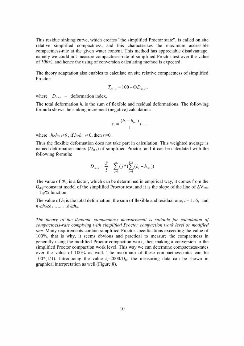
The theory of the dynamic compactness measurement is suitable for calculation of compactness-rate complying with simplified Proctor compaction work level or modified one. Many requirements contain simplified Proctor specifications exceeding the value of 100%, that is why, it seems obvious and practical to measure the compactness in generally using the modified Proctor compaction work, then making a conversion to the simplified Proctor compaction work level. This way we can determine compactness-rates over the value of 100% as well. The maximum of these compactness-rates can be 100*(1/). Introducing the value =2000/Dm, the measuring data can be shown in graphical interpretation as well (Figure 8).
11
Figure 7: Graphical interpretation of on-site relative compactness-rate
TrE% Calculation of B&C On-site Relative Dynamic Compaction-Rate (TrE%=85%-100%)
01002003004005006007008009001000
110012001300140015001600170018001900200021002200230024002500260027002800290030003100320033003400350036003700380039004000410042004300440045004600470048004900500051005200530054005500560057005800590060006100620063006400650066006700680069007000710072007300740075007600770078007900800081008200830084008500
0 1 2 3 4 5 6 7 8 9 10 11 12 13 14 15 16 17 18
Drop number
x c
oeff
ition
(de
form
atio
n in
dex
= x
/200
0)
12
6 Summary Beside the load bearing capacity the compaction is the most important qualifying feature in the civil engineering. In compactness measurements, the maximum dry density (dmax) determined with modified Proctor test is used as a reference density, but in Germany sometimes the simplified Proctor test results are applied for the same purpose. The ratio between maximum dry densities measured modified and simplified Proctor characteristically was in the range of 1.03-1.15, while the ratio of compaction work levels is 4.4. Characteristics of different compaction work levels can be seen very well in the Proctor curves. The dry side sections of curves are roughly parallel to each other, while on wet side from the maximum dry density, curves suit into the saturated lines. At a particular given water content, the more we compact the soil, the more the needed water content is reduced, but on the wet side, in lower compaction work, the optimum water content increment is obvious, but it curves lower compactness-rate. We developed the method, which is capable to measure the on site relative compactness-rate by B&C dynamic SP-LFWD test device. There are to possibilities to do it, one of them is the conversion calculation, the other on is using less number of drops. Having been examined possibilities, we think, it is better to chose the conversion calculation, so we measure in traditional way, using the modified Proctor compaction work, and the result is converted to simplified Proctor work with factor This conversion is always made so, that we chose values of Trd-m%, wopt-m and convert them to values of Trd-s%, wopt-
s, and the on site relative simplified Proctor is calculated with Trw-s the moisture correction coefficient, to the natural site water content at the time of measurement. The B&C dynamic compactness and bearing capacity test device can be made suitable to give both compactness-rates with a slight software modification. But the needed number of drops draws our attention to the fact that the compaction work level remarkably differs from each other in the case of simplified and modified Proctor test. As we take the performances of the most up to date compaction machines into consideration, we can say, the construction practice development tends toward application of higher compaction work level. Bibliography CEN-WA 15 846 Measuring Method for Dynamic Compactness & Bearing Capacity with SP-LFWD Comparison of B&C LFWD and sand filling method – Ms. Panarat – Ramkhamhaeng University, Thailand D. Adam – F. Kopf : Operational devices for compaction optimization and quality control (Continuous Compaction Control & Light Falling Weight Device) Dr. E. Imre – T.Q. Phong – I. Subert: The B&C in site compactness-ratetest – the basic method Dr. E. Imre: Modellillesztés és modelldiszkrimináció a B&C tömörödési görbe alakjának behatárolására Dr. Kézdi Árpád: Talajmechanika I. TK, 1972
13
Dr. Pusztai József – Dr. Imre Emőke – Dr. Lőrincz János – Subert István – Trang Quoc Phong: Nagyfelületű, dinamikus tömörségmérés kifejlesztése helyazonosítással és a tömörítőhengerek süllyedésének folyamatos helyszíni mérésével (Development of large-area, dynamic compactness measurement by site identification and the continuous on-site measurement of the depression of compacting rollers). COLAS jelentés. 2007. EN 13 286-2 Kötőanyag nélküli és hidraulikus kötőanyagú keverékek 2. Vizsgálati módszerek a laboratóriumi viszonyítási térfogatsűrűség és víztartalom meghatározására. Proctor-tömörítés (Mixtures without binding material and with hydraulic binding material 2. Test methods for the determination of the laboratory reference volume density and water content. Proctor-compaction) EN 13 286-3 Kötőanyag nélküli és hidraulikus kötőanyagú keverékek 3. A laboratóriumi viszonyítási térfogatsűrűség és víztartalom vizsgálati módszerei. Vibrosajtolás szabályozott paraméterekkel EN 13 286-4 Kötőanyag nélküli és hidraulikus kötőanyagú keverékek 4. A laboratóriumi viszonyítási térfogatsűrűség és víztartalom vizsgálati módszerei. Vibrokalapács EN 13 286-5 Kötőanyag nélküli és hidraulikus kötőanyagú keverékek 5. A laboratóriumi viszonyítási térfogatsűrűség és víztartalom vizsgálati módszerei. Vibroasztal Fáy M. – Király Á. – Subert I.: Egy földmű-tömörségi anomália feltárása és megoldása (Presentation and solution of an anomaly of earthwork density). Mélyépítéstudományi Szemle, 2006. Fáy M. – Király Á. – Subert I.: Közúti forgalom igénybevételének modellezése új, dinamikus tömörség- és teherbírásméréssel (Modelling of the straining of public road traffic by the new, dynamic compactness and bearing capacity measurement). Városi Közlekedés, 2006. Király Á. – Morvay Z.: Földmunkák minősítő vizsgálatainak hatékonysági kérdései Magyarországon (Efficiency issues of qualification tests used for earthworks, in Hungary) Metróber: ER-TRG01 Ellenőrzési rendszer próbatömörítések végrehajtására és értékelésére az M7 Zamárdi–Balatonszárszó szakaszán (Control system for the implementation and the evaluation of test compactions on the road section of M7 between Zamárdi and Balatonszárszó). Mérnöki Eljárási Utasítás. p. 10. MSZ 15 320 Földművek tömörségének meghatározása radioizotópos módszerrel (Determination of the compactness of earthworks by radioisotopic method) Report on usage of Andreas dynamic load bearing capacity and compactness deflectometer, University of Ljubljana, Katedra za mehaniko tal z laboratorijem Subert I. – Phong T.Q.: Az izotópos és dinamikus tömörségi fok szórásanalízise 2007–2008. (Analysis of Standard deviation of the isotopic and the dynamic compactness rate) Subert I. – Phong T.Q.: Proctor-vizsgálatok új értelmezési lehetőségei (Options for new interpretations of Proctor-tests). Mélyépítéstudományi Szemle, 2007. Subert I. – Phong T.Q.: Sürüségkorrekció alkalmazása dinamikus ejtősúlyos berendezéseknél, 2008. Subert I.: A dinamikus tömörség- és teherbírásmérés újabb paraméterei és a modulusok átszámíthatósági kérdései (Recent parameters of dynamic compactness and bearing capacity measurement and recalculation issues of moduluses). Közúti és Mélyépítési Szemle, 55. évf. 2005. 1. sz. p. 5. Subert I.: B&C – egy hasznos társ (B&C – a useful partner). Magyar Építő Fórum, 2004/25. szám p. 36. Subert I.: B&C dinamikus tömörségmérés (B&C dynamic compactness measurement). Mélyépítés, 2004 október–december pp. 38–39.
14
Subert I.: Dinamikus tömörségmérés a hazai autópályákon és városi helyreállításokon (Dynamic compactness measurement on Hungarian highways and urban reconstructions). Geotechnika Konferencia, Ráckeve. (2006. október 17–18.) Subert I.: Dinamikus tömörségmérés aktuális kérdései. A dinamikus tömörségmérés újabb tapasztalatai (Recent issues of dynamic compactness measurement. New experiences of the dynamic compactness measurement). Geotechnika Konferencia, Ráckeve (2005. október 18–20.) Subert I.: Új, környezetkímélő, gazdaságos mérőeszközök a közlekedésépítésben (New, environmental-friendly, economical measuring instruments in traffic building). Geotechnika Konferencia, Ráckeve (2004. október 26–27.) Subert: Method for measuring Compactness-rate with New Dynamic LFWD. XIII. Danube–European Conference on Geotechnical Engineering Ljubljana, Slovenia, 2006. ÚT 2-2.124 Dinamikus tömörség- és teherbírásmérés kistárcsás könnyűejtősúlyos berendezéssel (Dynamic compactness and bearing capacity measurement with small-plate light falling deflectometer)