Embed Size (px)
Citation preview

ROLLVIS SA 136, ch. du Pont-du-CentenaireCH-1228 Plan-les-OuatesGENEVA - SWITZERLANDCorrespondence: post box 590CH - 1212 GRAND-LANCY 1
Tél. +41 (0)22 706 90 40Fax +41 (0)22 706 90 49
Email : [email protected]: www.rollvis.com
Conversion tables
LENGTHmm m inches feet1 0,001 0,0394 0,0033
1000 1 39,3701 3,280825,4 0,0254 1 0,0833304,8 0,3048 12 1
SURFACEm2 cm2 mm2 sq.in sq.ft1 10000 1000000 1550 10,76
0,0001 1 100 0,155 0,00110,000001 0,01 1 0,00155 1,076E-050,0006 6,4516 645,16 1 0,00690,0929 929,0304 92903,04 144 1
LOADN kN Tonf kgf Lbf1 0,001 0,0001 0,1020 0,2248
1000 1 0,1020 101,9716 224,80909806,65 9,8067 1 1000 2 204,62349,8067 0,0098 0,001 1 2,20464,4482 0,0044 0,0005 0,4536 1
STIFFNESSN/mm N/µm lbf/in x 1E61 1000 5,7101
0,001 1 0,00570,1751 175,1268 1
VOLUMEm3 dm3 (liter) cm3 mm3 in3 ft3 gallons (US) fl oz1 1000 1000000 1000000000 61 023,7441 35,3147 264,1700 33813,7
0,001 1 1000 1000000 61,0237 0,0353 0,2642 33,81370,000001 0,001 1 1000 0,0610 3,53147E-05 0,0003 0,0338
0,000000001 0,000001 0,001 1 6,10237E-05 3,53147E-08 2,6417E-07 3,38137E-051,63871E-05 0,0164 16,3871 16 387,0640 1 0,0006 0,0043 0,55410,028316847 28,3168 28 316 28 316 846,5920 1 728,0000 1 7,4805 957,49740,003785441 3,7854 3 785 3 785 441,2800 231,0018 0,1337 1 127,99982,95738E-05 0,0296 29,57 29 573,8118 1,8047 0,0010 0,0078 1
TORQUENm Ncm Nmm daN.m daN.cm kgf.cm in.lbf ft.lbf1 100 1000 0,1 10 10,1972 8,8507 0,7376
0,01 1 10 0,001 0,1 0,1020 0,0885 0,00740,001 0,1 1 0,0001 0,01 0,0102 0,0089 0,0007
10 1000 10000 1 100 101,9716 88,5075 7,37560,1 10 100 0,01 1 1,0197 0,8851 0,0738
0,0981 9,8067 98,0665 0,0098 0,9807 1 0,8680 0,07230,1130 11,2985 112,9848 0,0113 1,1298 1,1521 1 0,08331,3558 135,5817 1 355,8175 0,1356 13,5582 13,8255 12 1
LINEAR SPEEDm/s mm/s m/min km/h in/s in/min ft/s ft/min mph1 1000 60 3,6 39,3701 2 362,2047 3,2808 196,8504 2,2369
0,001 1 0,06 0,0036 0,0394 2,3622 0,0033 0,1969 0,00220,0167 16,6667 1 0,06 0,6562 39,3701 0,0547 3,2808 0,03730,2778 277,7778 16,6667 1 10,9361 656,1680 0,9113 54,6807 0,62140,0254 25,4 1,524 0,0914 1 60 0,0833 5 0,05680,0004 0,4233 0,0254 0,0015 0,0167 1 0,0014 0,0833 0,00090,3048 304,8 18,288 1,0973 12 720 1 60 0,68180,00508 5,08 0,3048 0,0183 0,2 12 0,0167 1 0,01140,4470 447,0389 26,8223 1,6093 17,6000 1 055,9974 1,4667 87,9998 1
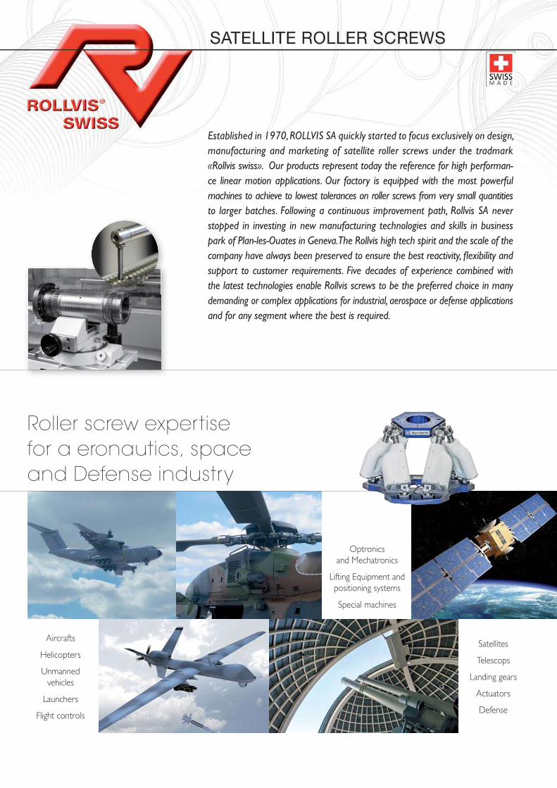
Established in 1970, ROLLVIS SA quickly started to focus exclusively on design, manufacturing and marketing of satellite roller screws under the tradmark «Rollvis swiss». Our products represent today the reference for high performan-ce linear motion applications. Our factory is equipped with the most powerful machines to achieve to lowest tolerances on roller screws from very small quantities to larger batches. Following a continuous improvement path, Rollvis SA never stopped in investing in new manufacturing technologies and skills in business park of Plan-les-Ouates in Geneva. The Rollvis high tech spirit and the scale of the company have always been preserved to ensure the best reactivity, fl exibility and support to customer requirements. Five decades of experience combined with the latest technologies enable Rollvis screws to be the preferred choice in many demanding or complex applications for industrial, aerospace or defense applications and for any segment where the best is required.
Aircrafts
Helicopters
Unmannedvehicles
Launchers
Flight controls
Optronicsand Mechatronics
Lifting Equipment andpositioning systems
Special machines
Satellites
Telescops
Landing gears
Actuators
Defense
Roller screw expertise for a eronautics, space and Defense industry
Today ROLLVIS is certifi ed
ISO 9001 : 2015
EN 9100 : 2016
Certifi cation
Application data list for roller screws
Maximal linear speed of the application :
Stroke :
length of screw :
Main load : Compression Tension
Rotation : Nut Screw shaft
Positioning of the screw : Vertical Horizontal
Specifi c limitations : Vibration : Shocks :
Expected lifetime Nb of cycles : Total time required - years-month :
Environnement : Humidity / Fluid / Dust :
Temperature range :
Geometric limitations : Nut/Shaft max diameter/Length :
Interfaces :
Motor torque :
Lubrifi cation requirement :
Preload - Backlash - Accuracy - Stiffness :Lead accuracy : G5 (23_m/300mm) G3 (12_m/300mm) G1 (6_m/300mm)
Manufacturing tolerances (ISO 3408-3) : Classe 5 Classe 3 Classe 1
Axial backlash : Standard Without backlash Preloading/Stiffness
Nut : Flange Cylindrical Double Specifi c design
Mounting conditions of the roller screwFixed - Free : XX ––––––
Fixde - Supported : XX–––––X
Fixed - Fixed : XX––––XX
Supported - Supported : X––––––X
Operation conditions :
Number of screws supporting the lead :
Max static load : Max. dynamic load :
Typical load chart (function of the stroke, forward and reverse stroke) :
Load
Stroke
Speed
Stroke
Notes / Remarks / Sketch :
- 1 -
RV
Ra
ng
eH
RV
Ra
ng
eR
VI
Ra
ng
eR
VR
Ra
ng
eR
VD
Ra
ng
eBe
arin
g un
its B
U
General Concepts• Satellite roller screws compared to
ball screws• Advantages of the Rollvis satellite roller screws
• Examples of applications
2
Types of roller screws 3 et 4
Identifi cation system 5
Accuracy - Effi ciency 6
Geometry 7
Preloading 8
Preloading examples 9
Mean speed and axial load 10
Nominal lifespan 11
Rigidity 12
Rotation speed 13
Driving torque 14 et 15
Calculation example 16 et 17
Lubrication 18 et 19
Handling advice 20
Preferred range
Screw RV range de 22 à 39
Screw HRV range de 40 à 45
Screw RVI range de 46 à 51
Screw RVR range de 52 à 57
Screw RVD range de 58 à 63
Bearing units BU de 64 à 68
Contents
To ensure that Rollvis roller screws always get benefi ts of the latest technologies, we have setup a new Research & Development department with a highly qualifi ed team, the most recent softwares and technologies in manufacturing, control & testing. Products & Processes are permanently optimized to make Rollvis screws one of the best on the market regarding reliability, performance and availability. Production and Quality systems are organized according to the latest ISO and EN standards. Testimonials from many high end customers praise Rollvis screws for the outstanding quality. With a global presence on all continents through subsidiaries or high tech distributor partners, we offer support and deliver our solutions wherever you are.
- 1 -
- 2 -
ROLLVIS satellite roller screws are used to transform rotary movements into linear movements
and vice versa. The rolling elements are threaded rollers between the screw and the nut. The high
number of points of contact enables satellite roller screws to support very heavy loads.
The ROLLVIS range comprises satellite roller screws with no recirculation (types RV and HRV),
inverted roller screws (type RVI), Differential roller screws (rype RVD) and screws with recirculating
rollers (type RVR). Bearing units are also proposed to equip the different roller screw designs.
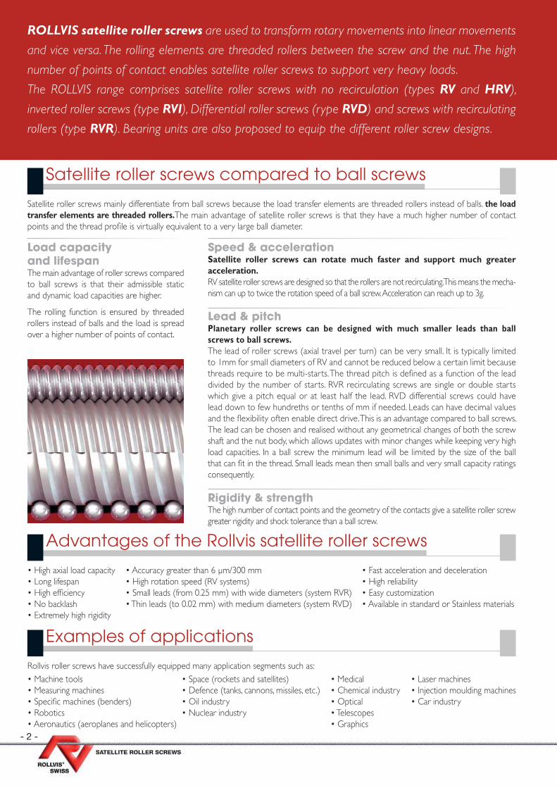
Load capacity and lifespan The main advantage of roller screws compared to ball screws is that their admissible static and dynamic load capacities are higher.
The rolling function is ensured by threaded rollers instead of balls and the load is spread over a higher number of points of contact.
Satellite roller screws mainly differentiate from ball screws because the load transfer elements are threaded rollers instead of balls. the load transfer elements are threaded rollers.The main advantage of satellite roller screws is that they have a much higher number of contact points and the thread profi le is virtually equivalent to a very large ball diameter.
Speed & acceleration Satellite roller screws can rotate much faster and support much greater acceleration. RV satellite roller screws are designed so that the rollers are not recirculating. This means the mecha-nism can up to twice the rotation speed of a ball screw. Acceleration can reach up to 3g.
Lead & pitch Planetary roller screws can be designed with much smaller leads than ball screws to ball screws. The lead of roller screws (axial travel per turn) can be very small. It is typically limited to 1mm for small diameters of RV and cannot be reduced below a certain limit because threads require to be multi-starts. The thread pitch is defi ned as a function of the lead divided by the number of starts. RVR recirculating screws are single or double starts which give a pitch equal or at least half the lead. RVD differential screws could have lead down to few hundreths or tenths of mm if needed. Leads can have decimal values and the fl exibility often enable direct drive. This is an advantage compared to ball screws. The lead can be chosen and realised without any geometrical changes of both the screw shaft and the nut body, which allows updates with minor changes while keeping very high load capacities. In a ball screw the minimum lead will be limited by the size of the ball that can fi t in the thread. Small leads mean then small balls and very small capacity ratings consequently.
Rigidity & strengthThe high number of contact points and the geometry of the contacts give a satellite roller screw greater rigidity and shock tolerance than a ball screw.
Satellite roller screws compared to ball screws
Advantages of the Rollvis satellite roller screws
Examples of applications
• High axial load capacity• Long lifespan• High effi ciency• No backlash• Extremely high rigidity
• Accuracy greater than 6 µm/300 mm• High rotation speed (RV systems)• Small leads (from 0.25 mm) with wide diameters (system RVR)• Thin leads (to 0.02 mm) with medium diameters (system RVD)
• Fast acceleration and deceleration• High reliability• Easy customization• Available in standard or Stainless materials
• Machine tools• Measuring machines• Specifi c machines (benders)• Robotics• Aeronautics (aeroplanes and helicopters)
• Space (rockets and satellites)• Defence (tanks, cannons, missiles, etc.)• Oil industry• Nuclear industry
• Medical• Chemical industry• Optical• Telescopes• Graphics
• Laser machines• Injection moulding machines• Car industry
Rollvis roller screws have successfully equipped many application segments such as:
- 3 -
Types of roller screws
The RVR roller screw is a design with recirculating rollers. The rollers are guided within a cage and their motion is controlled by a set of cams. This design combines extremely high positioning accuracy, resolution and stiffness while capacity ratings are at the highest thanks to a robust thread geometry.
This concept is perfect for all applications that need a very high accuracy under small or moderate speeds.
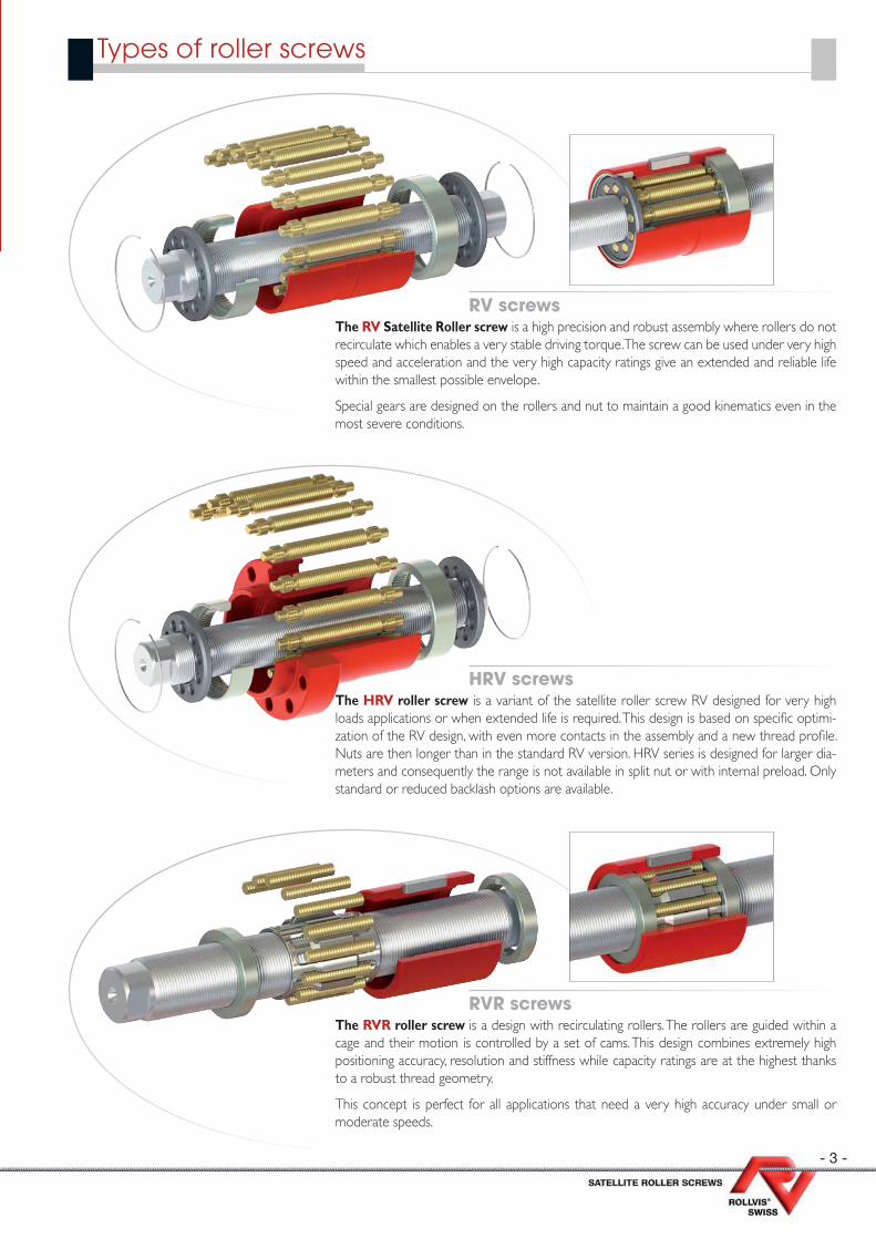
The RV Satellite Roller screw is a high precision and robust assembly where rollers do not recirculate which enables a very stable driving torque. The screw can be used under very high speed and acceleration and the very high capacity ratings give an extended and reliable life within the smallest possible envelope.
Special gears are designed on the rollers and nut to maintain a good kinematics even in the most severe conditions.
RVR screws
RV screws
The HRV roller screw is a variant of the satellite roller screw RV designed for very high loads applications or when extended life is required. This design is based on specifi c optimi-zation of the RV design, with even more contacts in the assembly and a new thread profi le. Nuts are then longer than in the standard RV version. HRV series is designed for larger dia-meters and consequently the range is not available in split nut or with internal preload. Only standard or reduced backlash options are available.
HRV screws
- 4 -
Types of roller screws ( ctd.)
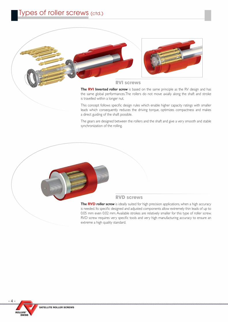
The RVD roller screw is ideally suited for high precision applications, when a high accuracy is needed. Its specifi c designed and adjusted components allow extremely thin leads of up to 0.05 mm even 0.02 mm. Available strokes are relatively smaller for this type of roller screw. RVD screw requires very specifi c tools and very high manufacturing accuracy to ensure an extreme a high quality standard.
The RVI Inverted roller screw is based on the same principle as the RV design and has the same global performances.The rollers do not move axially along the shaft and stroke is travelled within a longer nut.
This concept follows specifi c design rules which enable higher capacity ratings with smaller leads which consequently reduces the driving torque, optimizes compactness and makes a direct guiding of the shaft possible.
The gears are designed between the rollers and the shaft and give a very smooth and stable synchronization of the rolling.
RVD screws
RVI screws
- 5 -
Identifi cation system
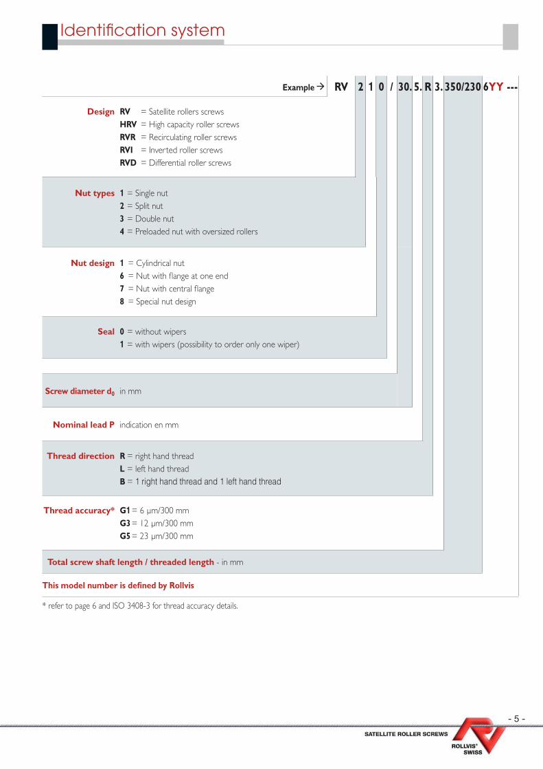
Example RV 2 1 0 / 30. 5. R 3. 350/230 6YY ---
Design RV = Satellite rollers screwsHRV = High capacity roller screwsRVR = Recirculating roller screwsRVI = Inverted roller screwsRVD = Differential roller screws
Nut types 1 = Single nut2 = Split nut3 = Double nut4 = Preloaded nut with oversized rollers
Nut design 1 = Cylindrical nut6 = Nut with fl ange at one end7 = Nut with central fl ange8 = Special nut design
Seal 0 = without wipers1 = with wipers (possibility to order only one wiper)
Screw diameter d0 in mm
Nominal lead P indication en mm
Thread direction R = right hand threadL = left hand threadB = 1 right hand thread and 1 left hand thread
Thread accuracy* G1 = 6 µm/300 mmG3 = 12 µm/300 mmG5 = 23 µm/300 mm
Total screw shaft length / threaded length - in mm
This model number is defi ned by Rollvis
* refer to page 6 and ISO 3408-3 for thread accuracy details.
- 6 -
Accuracy
Effi ciency
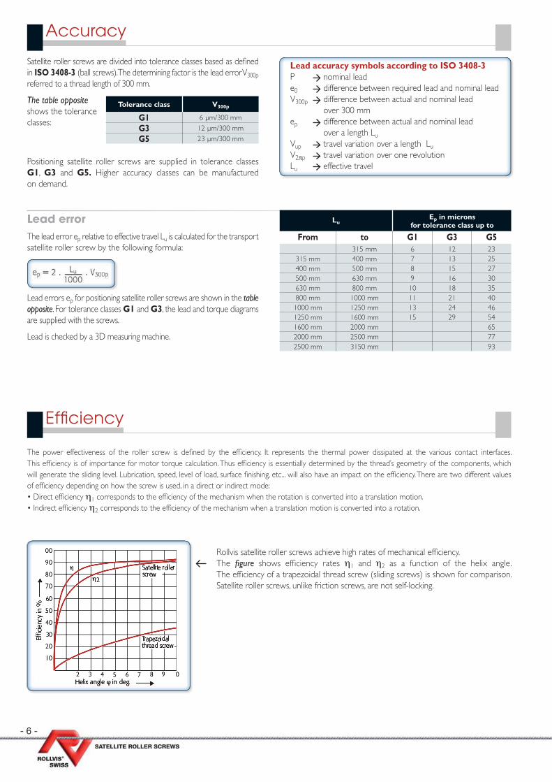
Satellite roller screws are divided into tolerance classes based as defi ned in ISO 3408-3 (ball screws). The determining factor is the lead error V300p referred to a thread length of 300 mm.
The table opposite shows the tolerance classes:
Positioning satellite roller screws are supplied in tolerance classes G1, G3 and G5. Higher accuracy classes can be manufactured on demand.
Lead accuracy symbols according to ISO 3408-3P nominal leade0 difference between required lead and nominal leadV300p difference between actual and nominal lead
over 300 mmep difference between actual and nominal lead
over a length LuVup travel variation over a length LuV2πp travel variation over one revolutionLu effective travel
Tolerance class V300p
G1 6 µm/300 mm
G3 12 µm/300 mm
G5 23 µm/300 mm
Lead errors ep for positioning satellite roller screws are shown in the table opposite. For tolerance classes G1 and G3, the lead and torque diagrams are supplied with the screws.
Lead is checked by a 3D measuring machine.
Lead error The lead error ep relative to effective travel Lu is calculated for the transport satellite roller screw by the following formula:
LuEp in microns
for tolerance class up to
From to G1 G3 G5315 mm 6 12 23
315 mm 400 mm 7 13 25400 mm 500 mm 8 15 27500 mm 630 mm 9 16 30630 mm 800 mm 10 18 35800 mm 1000 mm 11 21 401000 mm 1250 mm 13 24 461250 mm 1600 mm 15 29 541600 mm 2000 mm 652000 mm 2500 mm 772500 mm 3150 mm 93
The power effectiveness of the roller screw is defi ned by the effi ciency. It represents the thermal power dissipated at the various contact interfaces. This effi ciency is of importance for motor torque calculation. Thus effi ciency is essentially determined by the thread’s geometry of the components, which will generate the sliding level. Lubrication, speed, level of load, surface fi nishing, etc... will also have an impact on the effi ciency. There are two different values of effi ciency depending on how the screw is used, in a direct or indirect mode:• Direct effi ciency η1 corresponds to the effi ciency of the mechanism when the rotation is converted into a translation motion.• Indirect effi ciency η2 corresponds to the effi ciency of the mechanism when a translation motion is converted into a rotation.
Rollvis satellite roller screws achieve high rates of mechanical effi ciency. The fi gure shows effi ciency rates η1 and η2 as a function of the helix angle. The effi ciency of a trapezoidal thread screw (sliding screws) is shown for comparison. Satellite roller screws, unlike friction screws, are not self-locking.

- 7 -
Geometry
Nut geometry and shape
Single nuts have low axial backlash. This version can also be manufactured with zero backlash or even with a light preload. The split cylindrical nut is preloaded by clamping the two halves of the nut in a housing. A precision spacer ring is mounted between the two halves to maintain the required level of preloading. Split nuts with a fl ange at one end have a spacer ring designed to hold the halves apart. The halves are aligned by a parallel key. Double nuts are preloaded in the same way as split nuts. Cyclindrical nut types and central fl anged ones are then usually preloaded in compression whereas side fl anged nuts are preloaded in tension.
SPLIT NUTS:Nuts in two pieces, preloaded, without backlashSame dimensions as single nutsReduced load capacitiesWipers (on request)
DOUBLE NUTS:Two single nuts, preloaded, without backlashSame load capacities as single nutsAbout twice as long as single nutsWipers (on request)
SINGLE NUTS:Nuts in one piece with axial backlashWipers (on request)
60°
Shape A Shape B
60° 30°
FLANGE SHAPESExamples of typical fl ange shapes
Nut’s geometry can be customised as per customer’s specifi c needs.Nut’s geometry can be customised as per customer’s specifi c needs.
45°
- 8 -
Preloading
F1
Fv
F2
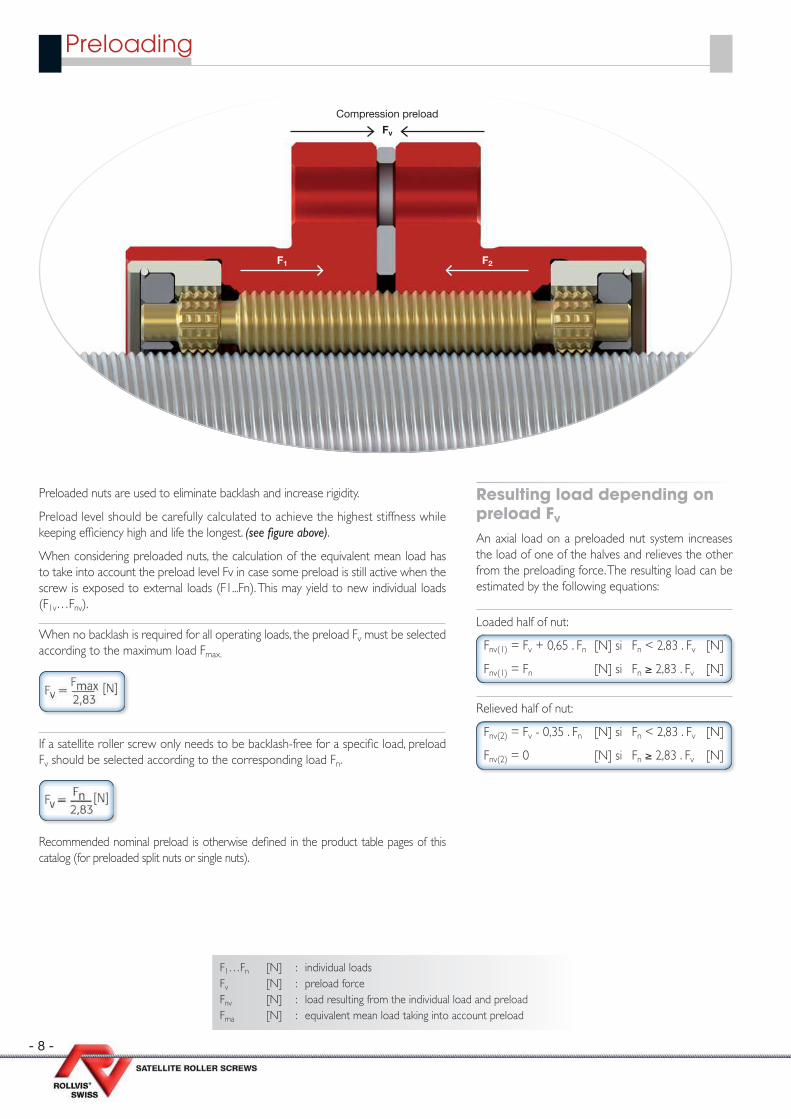
Compression preload
Preloaded nuts are used to eliminate backlash and increase rigidity.
Preload level should be carefully calculated to achieve the highest stiffness while keeping effi ciency high and life the longest. (see fi gure above).
When considering preloaded nuts, the calculation of the equivalent mean load has to take into account the preload level Fv in case some preload is still active when the screw is exposed to external loads (F1...Fn). This may yield to new individual loads (F1v…Fnv).
When no backlash is required for all operating loads, the preload Fv must be selected according to the maximum load Fmax.
If a satellite roller screw only needs to be backlash-free for a specifi c load, preload Fv should be selected according to the corresponding load Fn.
Recommended nominal preload is otherwise defi ned in the product table pages of this catalog (for preloaded split nuts or single nuts).
Resulting load depending on preload Fv
An axial load on a preloaded nut system increases the load of one of the halves and relieves the other from the preloading force. The resulting load can be estimated by the following equations:
Loaded half of nut:
Fnv(1) = Fv + 0,65 . Fn [N] si Fn < 2,83 . Fv [N]
Fnv(1) = Fn [N] si Fn ≥ 2,83 . Fv [N]
Relieved half of nut:
Fnv(2) = Fv - 0,35 . Fn [N] si Fn < 2,83 . Fv [N]
Fnv(2) = 0 [N] si Fn ≥ 2,83 . Fv [N]
F1…Fn [N] : individual loadsFv [N] : preload forceFnv [N] : load resulting from the individual load and preloadFma [N] : equivalent mean load taking into account preload
- 9 -
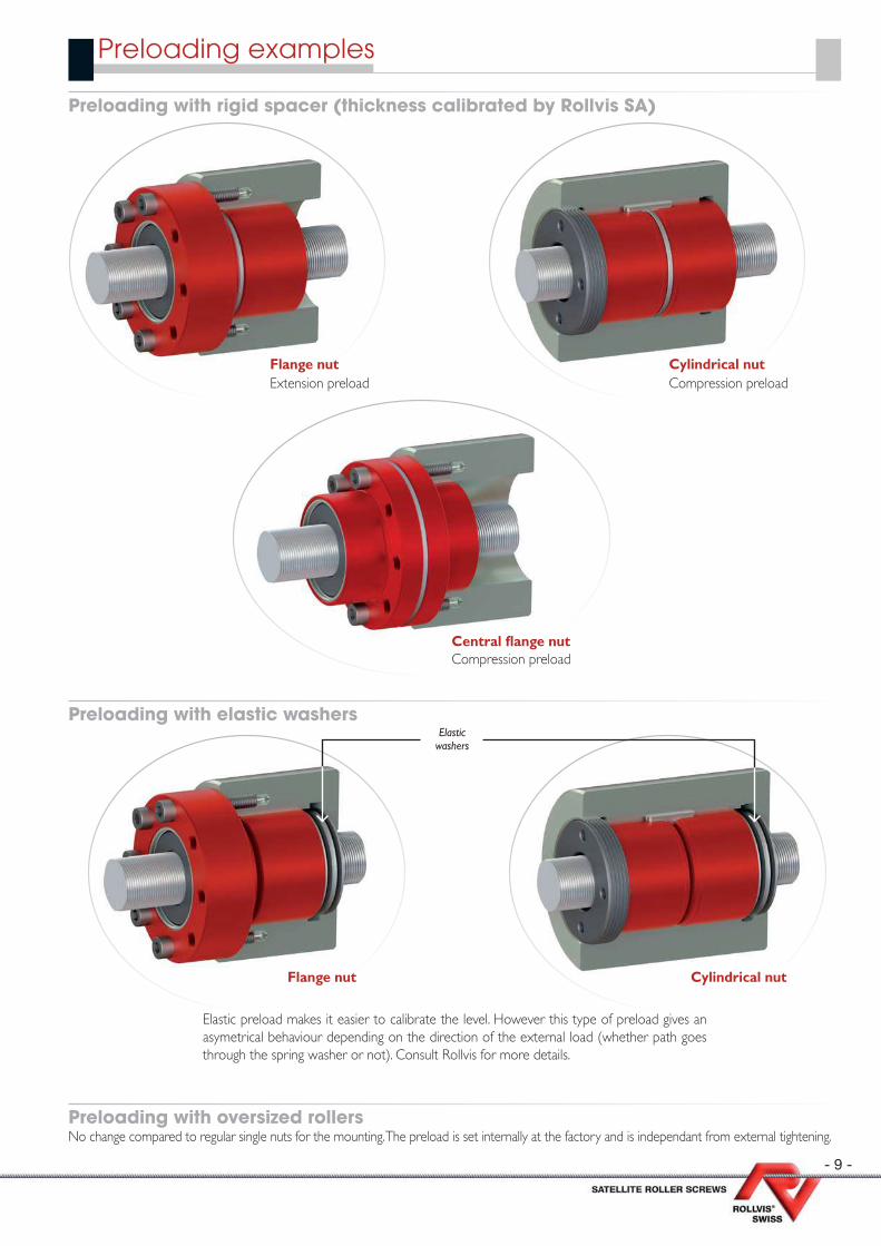
Preloading examples
Preloading with rigid spacer (thickness calibrated by Rollvis SA)
Preloading with elastic washers
Preloading with oversized rollersNo change compared to regular single nuts for the mounting. The preload is set internally at the factory and is independant from external tightening.
Central fl ange nutCompression preload
Flange nutExtension preload
Cylindrical nutCompression preload
Elastic preload makes it easier to calibrate the level. However this type of preload gives an asymetrical behaviour depending on the direction of the external load (whether path goes through the spring washer or not). Consult Rollvis for more details.
Elastic washers
Flange nut Cylindrical nut
- 10 -
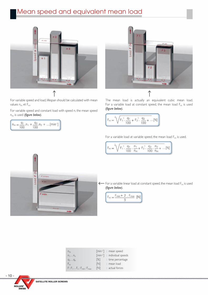
Mean speed and equivalent mean load
For variable speed and load, lifespan should be calculated with mean values nm et Fm.
For variable speed and constant load with speed n, the mean speed nm is used (fi gure below).
The mean load is actually an equivalent cubic mean load. For a variable load at constant speed, the mean load Fm is used (fi gure below).
For a variable load at variable speed, the mean load Fm is used.
For a variable linear load at constant speed, the mean load Fm is used (fi gure below).
nm [min-1] : mean speed n1…nn [min-1] : individual speedsq1…qn [%] : time percentageFm [N] : mean loadF ; F1…Fn ; Fmin ; Fmax [N] : actual forces
- 11 -
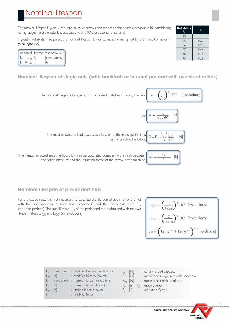
Nominal lifespan
The nominal lifespan L10 or Lh of a satellite roller screw corresponds to the possible achievable life considering rolling fatigue failure mode. It is evaluated with a 90% probability of survival.
If greater reliability is required, the nominal lifespan L10 or Lh must be multiplied by the reliability factor fr (table opposite).
updated lifetime, respectively Ln = L10 . fr [ revolutions] Lhn = Lh . fr [h]
Reliability % fr
90 195 0,6296 0,5397 0,4498 0,33
99 0,21
Nominal lifespan of single nuts (with backlash or internal preload with oversized rollers)
The nominal lifespan of single nuts is calculated with the following formula:
or
The required dynamic load capacity as a function of the expected life time, can be calculated as follow:
The lifespan in actual machine hours LhN can be calculated considering the ratio between the roller screw life and the utilisation factor of the screw in the machine.
Nominal lifespan of preloaded nuts
For preloaded nuts, it is fi rst necessary to calculate the lifespan of each half of the nut with the corresponding dynamic load capacity C and the mean axial load Fma (including preload). The total lifespan L10 of the preloaded nut is obtained with the two lifespan values L10(1) and L10(2) (in revolutions).
Ln [revolutions] : modifi ed lifespan (revolutions)Lhn [h] : modifi ed lifespan (hours)L10 [revolutions] : nominal lifespan (revolutions)Lh [h] : nominal lifespan (hours)LhN [h] : lifetime in actual hoursfr [-] : reliability factor
C [N] : dynamic load capacityFm [N] : mean load (single nut with backlash)Fma [N] : mean load (preloaded nut)nm [min-1] : mean speedfN [-] : utilisation factor

- 12 -
Satellite roller screw rigidity The overall rigidity Cges of a satellite roller screw is the combination of the following individual rigidity values:
Cme nut rigidityCSp screw rigidity
Screw rigidity CS
Screw rigidity CS can be calculated with the following simplifi ed formula:
Permissible buckling force Fknzul Permissible buckling force can be calculated with the following formula:
0.8 corresponds to the safety factor : = 1
1,25
CL bearing rigidityCu r igidity of the surrounding
construction
Fv [N] : preloading forceFn [N] : axial loadCme [N/µm] : nut rigidityCs [N/µm] : screw rigidityfk [N2/3/µm] : rigidity factor
fm [-] : correction factorL [mm] : free screw lengthd0 [mm] : nominal diameter of screwFknzul [N] : permissible buckling force fkn [-] : correction factor for bearing type
Rigidity
Cas 1 : fkn = 0,25
Cas 2 : fkn = 1,0
Cas 3 : fkn = 2,0
Cas 4 : fkn = 4,0
- 13 -
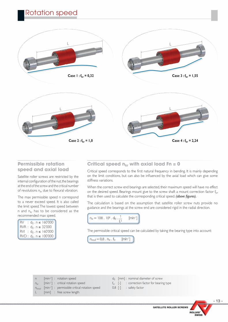
Rotation speed
Permissible rotation speed and axial load Satellite roller screws are restricted by the internal confi guration of the nut, the bearings at the end of the screw and the critical number of revolutions nkr due to fl exural vibration.
The max permissible speed n correspond to a never exceed speed. It is also called the limit speed. The lowest speed between n and nkr has to be considered as the recommended max speed.
RV : d0 . n ≤ 160’000RVR : d0 . n ≤ 32’000RVI : d0 . n ≤ 160’000RVD : d0 . n ≤ 100’000
Critical speed nkr with axial load Fn = 0 Critical speed corresponds to the fi rst natural frequency in bending. It is mainly depending on the limit conditions, but can also be infl uenced by the axial load which can give some stiffness variations.
When the correct screw end bearings are selected, their maximum speed will have no effect on the desired speed. Bearings mount give to the screw shaft a mount correction factor fkr, that is then used to calculate the corresponding critical speed. (above fi gures).
The calculation is based on the assumption that satellite roller screw nuts provide no guidance and the bearings at the screw end are considered rigid in the radial direction.
n [min-1] : rotation speednkr [min-1] : critical rotation speednkrzul [min-1] : permissible critical rotation speedL [mm] : free screw length
d0 [mm] : nominal diameter of screw fkr [-] : correction factor for bearing type0,8 [-] : safety factor
The permissible critical speed can be calculated by taking the bearing type into account:
Case 1 : fkr = 0,32
L
Case 2 : fkr = 1,0
L
Case 3 : fkr = 1,55
L
C 3 f 1 55
Case 4 : fkr = 2,24
L
- 14 -
Screw lead P
J2
J1
JM
nM
MM
i = D1D2
= 1D2
F
v
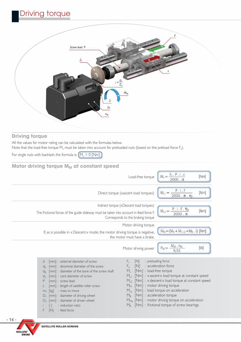
Driving torque
d [mm] : external diameter of screw d0 [mm] : dnominal diameter of the screw dB [mm] : diameter of the bore of the screw shaftd2 [mm] : core diameter of screwP [mm] : screw leadL [mm] : length of satellite roller screwmT [kg] : mass to moveD1 [mm] : diameter of driving wheelD2 [mm] : diameter of driven wheeli [-] : reduction ratioF [N] : feed force
Fv [N] : preloading force Fa [N] : acceleration force Mv [Nm] : load-free torqueML1 [Nm] : « ascent » load torque at constant speedML2 [Nm] : « descent » load torque at constant speedMM [Nm] : motor driving torqueMLa [Nm] : load torque on acceleration MB [Nm] : acceleration torqueMMa [Nm] : motor driving torque on accelerationMR [Nm] : frictional torque of screw bearings
Motor driving torque MM at constant speed
Load-free torque
Direct torque («ascent load torque»)
Indirect torque («Descent load torque»)
The frictional forces of the guide slideway must be taken into account in feed force F.Corresponds to the braking torque
Motor driving torque
If, as is possible in « Descent » mode, the motor driving torque is negative, the motor must have a brake.
Motor driving power
Driving torque All the values for motor rating can be calculated with the formulas below.Note that the load-free torque Mv must be taken into account for preloaded nuts (based on the preload force Fv).
For single nuts with backlash, the formula is: Mv = 0 [Nm]

- 15 -
JM [kgm2] : moment of inertia of motorJR [kgm2] : rotary moment of inertia of screwJT [kgm2] : translatory moment of inertia of screwJ [kgm2] : moment of inertia J1 [kgm2] : moment of inertia of driving wheelJ2 [kgm2] : moment of inertia of driven wheelPM [W] : driving power of motor at constant speedPMa [W] : driving power of motor on accelerationsB [mm] : acceleration path tB [s] : acceleration time
v [m/s] : speed ratenM [min-1] : rotation speed of motorη [-] : mechanical effi ciency of gearingη1 [-] : mechanical effi ciency of satellite roller screw
for « ascent » η1 = 0,71…0,89η2 [-] : mechanical effi ciency of satellite roller screw
for « descent » η2 = 0,61…0,85c [-] : coeffi cient of friction referred to preloading
c = 0,1…0,5( for effi ciencies η1 + η2 see page 6)
Motor driving torque MMa with acceleration
The rotary moment of inertia of screw JR can be approximated with the formulae below.Please contact Rollvis Engineering if you need exact fi gures of roller screw moment of inertia.
Load torque
Moment of inertia (translation)
Screw moment of inertia (rotation)
Sum of reduced moments of inertia
Motor speed
Acceleration torque MB = f (nM)
Acceleration torque MB = f (sB)
Acceleration time tB = f (nM)
Acceleration time tB = f (sB)
Rotation speed reached after acceleration
Linear stroke travelled during acceleration
Motor driving torque
Motor driving power
- 16 -
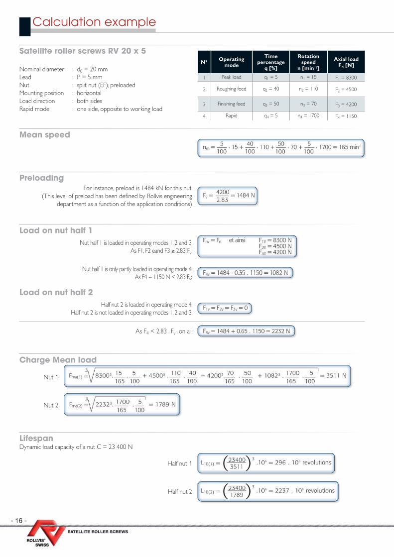
Satellite roller screws RV 20 x 5
Nominal diameter : d0 = 20 mmLead : P = 5 mmNut : split nut (EF), preloadedMounting position : horizontalLoad direction : both sidesRapid mode : one side, opposite to working load
Mean speed
PreloadingFor instance, preload is 1484 kN for this nut.
(This level of preload has been defi ned by Rollvis engineering department as a function of the application conditions)
Load on nut half 1 Nut half 1 is loaded in operating modes 1, 2 and 3.
As F1, F2 eand F3 ≥ 2.83 Fv:
Nut half 1 is only partly loaded in operating mode 4.As F4 = 1150 N < 2.83 Fv:
Load on nut half 2 Half nut 2 is loaded in operating mode 4.
Half nut 2 is not loaded in operating modes 1, 2 and 3.
As F4 < 2.83 . Fv , on a :
Charge Mean load
Nut 1
Nut 2
Lifespan Dynamic load capacity of a nut C = 23 400 N
Half nut 1
Half nut 2
N° Operating mode
Timepercentage
q [%]
Rotation speed
n [min-1]
Axial load Fn [N]
1 Peak load q1 = 5 n1 = 15 F1 = 8300
2 Roughing feed q2 = 40 n2 = 110 F2 = 4500
3 Finishing feed q3 = 50 n3 = 70 F3 = 4200
4 Rapid q4 = 5 n4 = 1700 F4 = 1150
Calculation example
- 17 -
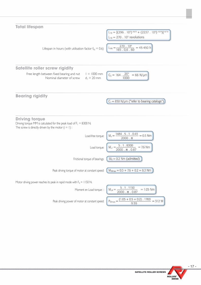
Total lifespan
Lifespan in hours (with utilisation factor fN = 0.6)
Satellite roller screw rigidity Free length between fi xed bearing and nut 1 = 1000 mm Nominal diameter of screw d1 = 20 mm
Bearing rigidity
Driving torque Driving torque MM is calculated for the peak load of F1 = 8300 N. The screw is directly driven by the motor (i = 1) :
Load-free torque:
Load torque:
Frictional torque of bearings:
Peak driving torque of motor at constant speed:
Motor driving power reaches its peak in rapid mode with F4 = 1150 N.
Moment en Load torque: :
Peak driving power of motor at constant speed:
- 18 -
Lubrication
Lubricants used for satellite roller screws are generally the same as for ball bearings. Oil or grease can both be used, depending on the appli-cation conditions and how maintenance is managed. Without specifi c request from customer, Rollvis use its standard grease. As a function of customer’s application, we are able to defi ne and offer the most appropriate lubricant.
Circulating mineral oils with EP additives to enhance resistance to aging and corrosion in compliance with CL based on DIN 51517, part 2, are especially suitable for the lubrication of satellite roller screws. Speed, ambient temperature and operating temperature are determining factors in the choice of viscosity.
The amount of oil required depends on the screw diameter, the number of supporting rollers and the amount of heat to dissipate. 1 cm3/h (for small screw diameters) to 30 cm3/h (for large screw diameters) can be used as reference values. Rollvis Engineering can support to calculate the power to be dissipated by the screw and make recommendation on the fl ow of oil to cool down the screw.
The shortest possible lubrication intervals (…5 minutes) are recommended for high loads and longer intervals (5 minutes to 1 hr) for low loads. Automatic lubrication is recommended for high loads and speeds.
For immersion lubrication, the oil level should be such that the bottommost roller is completely submerged in the oil. The amount of oil and the oil-change intervals depend on the loading and installation.
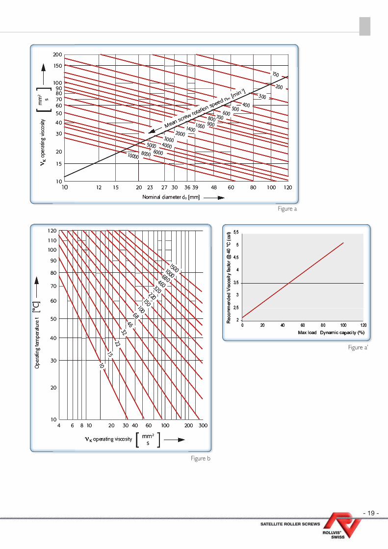
The viscosity of the oil should be chosen to enable an adequate fi lm of lubricant to form on the contact surfaces.
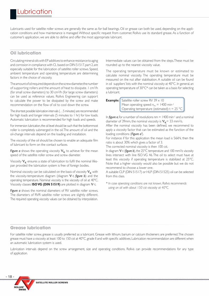
Figure a shows the operating viscosity νκ to achieve for the mean speed of the satellite roller screw and screw diameter.
Viscosity νκ ensures a state of lubrication to fulfi l the nominal lifes-pan provided the lubrication system is free of foreign bodies.
Nominal viscosity can be calculated on the basis of viscosity νκ with the viscosity-temperature diagram (diagram ν-t, fi gure b) and the operating temperature. Nominal viscosity is the viscosity of oil at 40°C. Viscosity classes ISO VG (DIN 51519) are plotted in diagram ν-t.
Figure a shows the nominal diameters of RV satellite roller screws. The diameters of RVR satellite roller screws are slightly different. The required operating viscosity values can be obtained by interpolation.
Intermediate values can be obtained from the steps. These must be rounded up to the nearest viscosity value.
The operating temperature must be known or estimated to calculate nominal viscosity. The operating temperature must be measured on the nut after stabilisation. A suitable oil can be found in oil suppliers’ lists with the nominal viscosity at 40°C. In general, an operating temperature of 30°C* can be taken as a basis for selecting a lubricant.
Example: Satellite roller screw RV 39 x 10Mean operating speed: nm = 1400 min-1
Operating temperature (estimated): t = 25 °C
In fi gure a, for a number of revolutions nm = 1400 min-1 and a nominal diameter of 39mm, the nominal viscosity is νκ= 33 mm2/s. After the nominal viscosity has been defi ned, we recommend to apply a viscosity factor that can be estimated as the function of the loading conditions (Figure a’).For instance if for this application the mean load is 56kN, then the ratio is about 30% which gives a factor of 3. The corrected nominal viscosity is then 100 cst.In diagram ν-t (fi gure b), the 25°C temperature and 100 mm2/s viscosity lines intersect with line ISO VG 46. The oil to select must have at least this viscosity if operating temperature is stabilized at 25°C. Note that a higher viscosity would also be possible but we do not recommend to choose a lower one. A suitable CLP (DIN 51517) or HLP (DIN 51525) oil can be selected from this class.
* In case operating conditions are not known, Rollvis recommends using an oil with about 150 cst viscosity at 40°C.
Oil lubrication
Grease lubricationFor satellite roller screw, grease is usually preferred as a lubricant. Grease with lithium, barium or calcium thickeners are preferred. The chosen grease must have a viscosity at least 100 to 150 cst at 40°C, grade II and with specifi c additives. Lubrication recommendation are different when an automatic lubrication system is used.
Lubrication intervals depend on the screw arrangement, size and operating conditions. Rollvis can provide recommendations for any type of application.
- 19 -
Figure a
Figure a’
Figure b
- 20 -
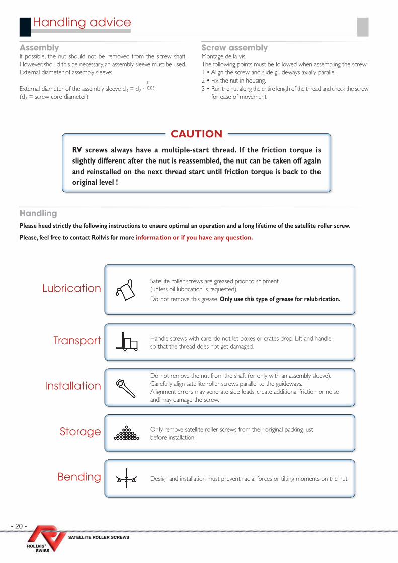
Handling advice
Assembly If possible, the nut should not be removed from the screw shaft.However, should this be necessary, an assembly sleeve must be used.External diameter of assembly sleeve: 0External diameter of the assembly sleeve d3 = d2 - 0,05
(d2 = screw core diameter)
HandlingPlease heed strictly the following instructions to ensure optimal an operation and a long lifetime of the satellite roller screw.
Please, feel free to contact Rollvis for more information or if you have any question.
Screw assembly Montage de la vis The following points must be followed when assembling the screw: 1 • Align the screw and slide guideways axially parallel.2 • Fix the nut in housing.3 • Run the nut along the entire length of the thread and check the screw
for ease of movement
RV screws always have a multiple-start thread. If the friction torque is slightly different after the nut is reassembled, the nut can be taken off again and reinstalled on the next thread start until friction torque is back to the original level !
CAUTION
Satellite roller screws are greased prior to shipment (unless oil lubrication is requested).
Do not remove this grease. Only use this type of grease for relubrication. Lubrication
Handle screws with care: do not let boxes or crates drop. Lift and handle so that the thread does not get damaged.
Transport
Do not remove the nut from the shaft (or only with an assembly sleeve).Carefully align satellite roller screws parallel to the guideways.Alignment errors may generate side loads, create additional friction or noise and may damage the screw.
Installation
Only remove satellite roller screws from their original packing just before installation.
Storage
Design and installation must prevent radial forces or tilting moments on the nut. Bending
- 21 -
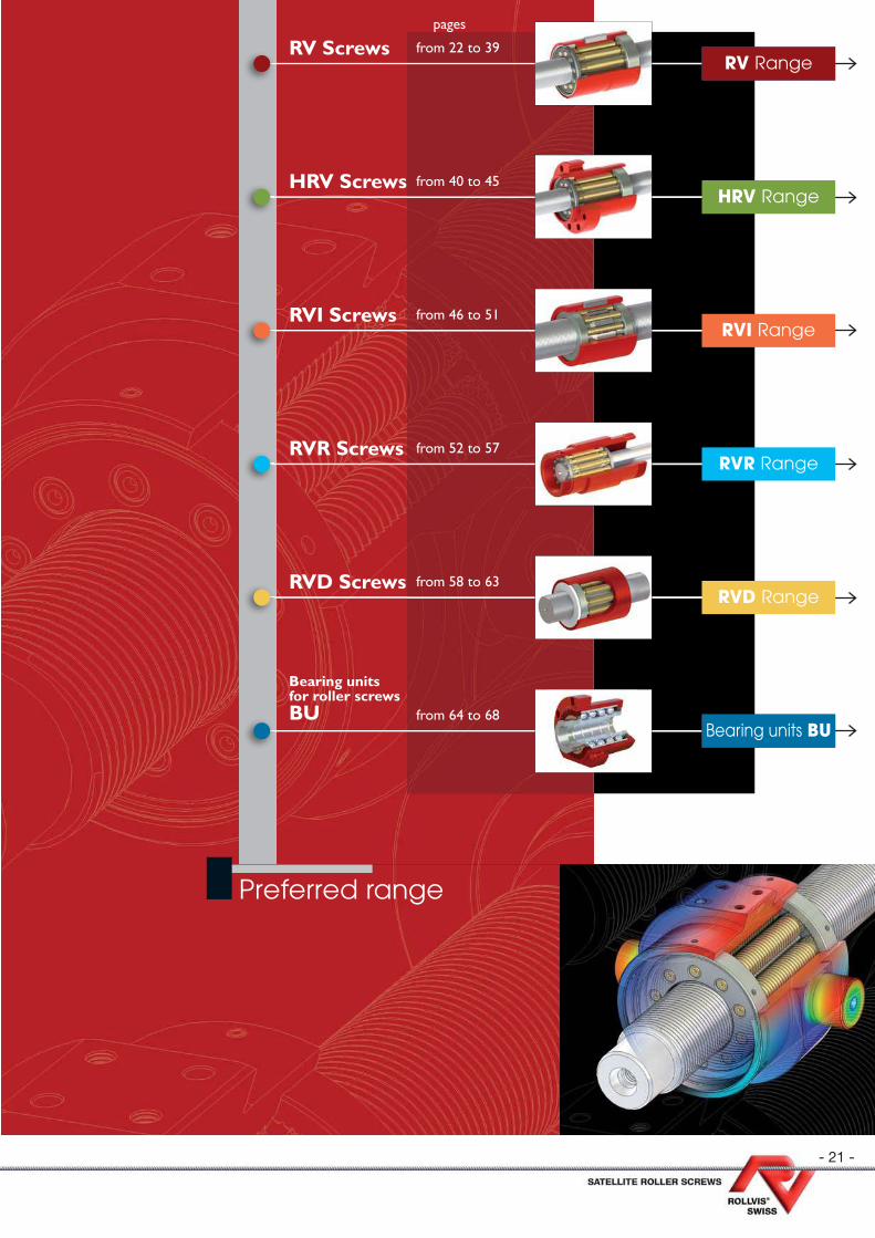
RV Range
HRV Range
RVI Range
RVR Range
RVD Range
Bearing units BU
RV Screws from 22 to 39
HRV Screws from 40 to 45
RVI Screws from 46 to 51
RVR Screws from 52 to 57
RVD Screws from 58 to 63
Bearing units for roller screwsBU from 64 to 68
Preferred range
pages
- 22 -
RV
Ra
ng
e
Screw diameter
(D)
Number of starts
(N)
Lead (P)
1 2 3 4 5 6 8 10 12 15 18 20 24 25 30 35 36 40 42 503,5 3 X X5 3 X X X7 4 X X X X8 4 X X X X
10 4 X5 X X X
12 4 X5 X X X X X X
15 5 X X X X X X18 5 X X X X X X X20 5 X X X X X X X21 5 X X X X X X X23 5 X X X X X X X
25 6 X X X5 X X X X X X X
27 5 X X X X X X X30 5 X X X X X X X X X
36 6 X X X X5 X X X X X X X X
39 5 X X X X X X X X X44 6 X X X X X
48 6 X X X X X X X X X5 X X X X X X
51 5 X X X X X56 6 X X X X X X
60 6 X X X X X X X5 X X X X X X X
64 6 X X X X X X70 6 X X X X X X75 5 X X X X X80 6 X X X X X87 5 X X X X X92 6 X X X X X
100 6 X X X X5 X X X X X
120 6 X X X X5 X X X X X
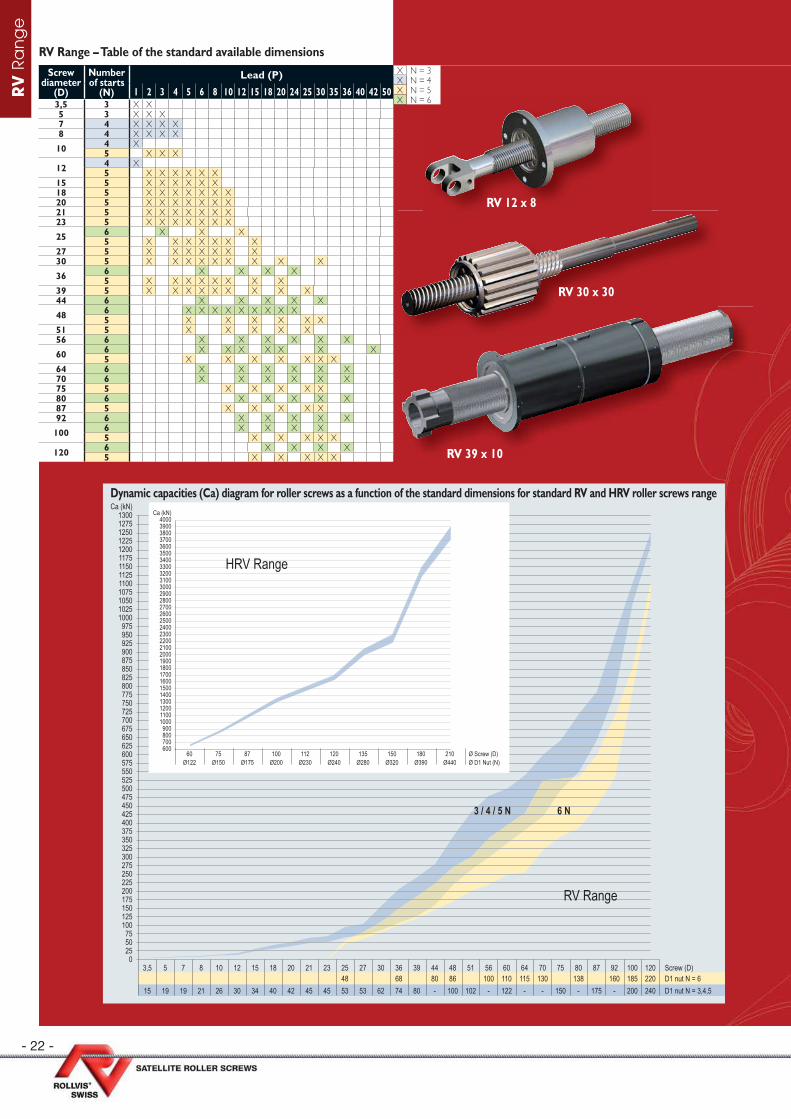
RV Range – Table of the standard available dimensions
RV 30 x 30
RV 39 x 10
RV 12 x 8
3,5 5 7 8 10 12 15 18 20 21 23 25 27 30 36 39 44 48 51 56 60 64 70 75 80 87 92 100 120
15 19 19 21 26 30 34 40 42 45 45 53 53 62 74 80 - 100 102 - 122 - - 150 - 175 - 200 24048 68 80 86 100 110 115 130 138 160 185 220
Screw (D)D1 nut N = 6D1 nut N = 3,4,5
1300127512501225120011751150112511001075105010251000
975950925900875850825800775750725700675650625600575550525500475450425400375350325300275250225200175150125100
755025
0
Ca (kN)
RV Range
6 N3 / 4 / 5 N
Dynamic capacities (Ca) diagram for roller screws as a function of the standard dimensions for standard RV and HRV roller screws range
210Ø440
180Ø390
150Ø320
135Ø280
120Ø240
112Ø230
100Ø200
87Ø175
75Ø150
60Ø122
Ø Screw (D)Ø D1 Nut (N)
4000390038003700360035003400330032003100300029002800270026002500240023002200210020001900180017001600150014001300120011001000
900800700600
Ca (kN)
HRV Range
X N = 3X N = 4X N = 5X N = 6
- 23 -
RV
Ra
ng
eR
V R
an
ge
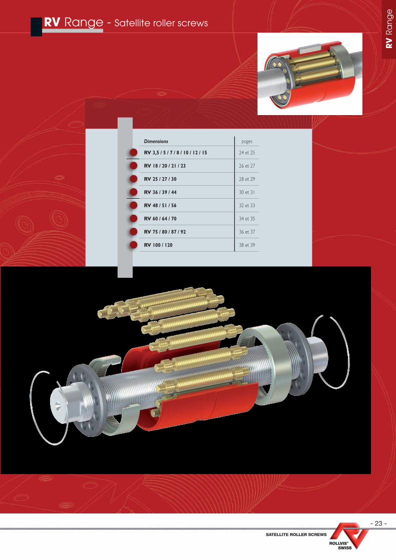
RV Range - Satellite roller screws
Dimensions pages
RV 3,5 / 5 / 7 / 8 / 10 / 12 / 15 24 et 25
RV 18 / 20 / 21 / 23 26 et 27
RV 25 / 27 / 30 28 et 29
RV 36 / 39 / 44 30 et 31
RV 48 / 51 / 56 32 et 33
RV 60 / 64 / 70 34 et 35
RV 75 / 80 / 87 / 92 36 et 37
RV 100 / 120 38 et 39
- 24 -
RV
Ra
ng
e
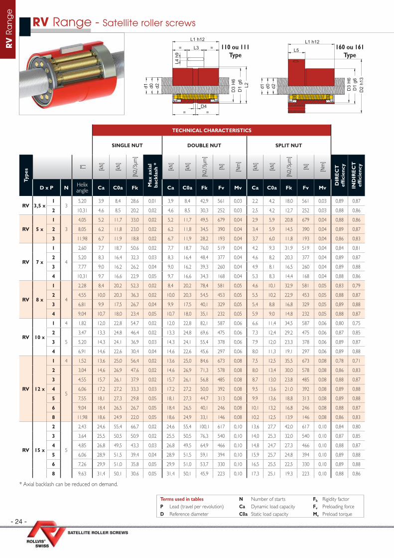
TECHNICAL CHARACTERISTICS
SINGLE NUT DOUBLE NUT SPLIT NUT
Type
s [°] [kN
]
[kN
]
[N2/
3µm
]
Max
axi
al
back
lash
*
[kN
]
[kN
]
[N2/
3µm
]
[N]
[Nm
]
[kN
]
[kN
]
[N2/
3µm
]
[N]
[Nm
]
DIR
EC
T
effi
cien
cy
IND
IRE
CT
ef
fi ci
ency
D x P N Helix angle Ca C0a Fk Ca C0a Fk Fv Mv Ca C0a Fk Fv Mv
RV 3,5 x1
35,20 3,9 8,4 28,6 0,01 3,9 8,4 42,9 561 0,03 2,2 4,2 18,0 561 0,03 0,89 0,87
2 10,31 4,6 8,5 20,2 0,02 4,6 8,5 30,3 252 0,03 2,5 4,2 12,7 252 0,03 0,88 0,86
RV 5 x
1
3
4,05 5,2 11,7 33,0 0,02 5,2 11,7 49,5 679 0,04 2,9 5,9 20,8 679 0,04 0,88 0,86
2 8,05 6,2 11,8 23,0 0,02 6,2 11,8 34,5 390 0,04 3,4 5,9 14,5 390 0,04 0,89 0,87
3 11,98 6,7 11,9 18,8 0,02 6,7 11,9 28,2 193 0,04 3,7 6,0 11,8 193 0,04 0,86 0,83
RV 7 x
1
4
2,60 7,7 18,7 50,6 0,02 7,7 18,7 76,0 519 0,04 4,2 9,3 31,9 519 0,04 0,84 0,81
2 5,20 8,3 16,4 32,3 0,03 8,3 16,4 48,4 377 0,04 4,6 8,2 20,3 377 0,04 0,89 0,87
3 7,77 9,0 16,2 26,2 0,04 9,0 16,2 39,3 260 0,04 4,9 8,1 16,5 260 0,04 0,89 0,88
4 10,31 9,7 16,6 22,9 0,05 9,7 16,6 34,3 168 0,04 5,3 8,3 14,4 168 0,04 0,88 0,86
RV 8 x
1
4
2,28 8,4 20,2 52,3 0,02 8,4 20,2 78,4 581 0,05 4,6 10,1 32,9 581 0,05 0,83 0,79
2 4,55 10,0 20,3 36,3 0,02 10,0 20,3 54,5 453 0,05 5,5 10,2 22,9 453 0,05 0,88 0,87
3 6,81 9,9 17,5 26,7 0,04 9,9 17,5 40,1 329 0,05 5,4 8,8 16,8 329 0,05 0,89 0,88
4 9,04 10,7 18,0 23,4 0,05 10,7 18,0 35,1 232 0,05 5,9 9,0 14,8 232 0,05 0,88 0,87
RV 10 x
1 4 1,82 12,0 22,8 54,7 0,02 12,0 22,8 82,1 587 0,06 6,6 11,4 34,5 587 0,06 0,80 0,75
2
5
3,47 13,3 24,8 46,4 0,02 13,3 24,8 69,6 475 0,06 7,3 12,4 29,2 475 0,06 0,87 0,85
3 5,20 14,3 24,1 36,9 0,03 14,3 24,1 55,4 378 0,06 7,9 12,0 23,3 378 0,06 0,89 0,87
4 6,91 14,6 22,6 30,4 0,04 14,6 22,6 45,6 297 0,06 8,0 11,3 19,1 297 0,06 0,89 0,88
RV 12 x
1 4 1,52 13,6 25,0 56,4 0,02 13,6 25,0 84,6 673 0,08 7,5 12,5 35,5 673 0,08 0,78 0,71
2
5
3,04 14,6 26,9 47,6 0,02 14,6 26,9 71,3 578 0,08 8,0 13,4 30,0 578 0,08 0,86 0,83
3 4,55 15,7 26,1 37,9 0,02 15,7 26,1 56,8 485 0,08 8,7 13,0 23,8 485 0,08 0,88 0,87
4 6,06 17,2 27,2 33,3 0,03 17,2 27,2 50,0 392 0,08 9,5 13,6 21,0 392 0,08 0,89 0,88
5 7,55 18,1 27,3 29,8 0,05 18,1 27,3 44,7 313 0,08 9,9 13,6 18,8 313 0,08 0,89 0,88
6 9,04 18,4 26,5 26,7 0,05 18,4 26,5 40,1 246 0,08 10,1 13,2 16,8 246 0,08 0,88 0,87
8 11,98 18,6 24,9 22,0 0,05 18,6 24,9 33,1 146 0,08 10,2 12,5 13,9 146 0,08 0,86 0,83
RV 15 x
2
5
2,43 24,6 55,4 66,7 0,02 24,6 55,4 100,1 617 0,10 13,6 27,7 42,0 617 0,10 0,84 0,80
3 3,64 25,5 50,5 50,9 0,02 25,5 50,5 76,3 540 0,10 14,0 25,3 32,0 540 0,10 0,87 0,85
4 4,85 26,8 49,5 43,3 0,03 26,8 49,5 64,9 466 0,10 14,8 24,7 27,3 466 0,10 0,88 0,87
5 6,06 28,9 51,5 39,4 0,04 28,9 51,5 59,1 394 0,10 15,9 25,7 24,8 394 0,10 0,89 0,88
6 7,26 29,9 51,0 35,8 0,05 29,9 51,0 53,7 330 0,10 16,5 25,5 22,5 330 0,10 0,89 0,88
8 9,63 31,4 50,1 30,6 0,05 31,4 50,1 45,9 223 0,10 17,3 25,1 19,3 223 0,10 0,88 0,86
* Axial backlash can be reduced on demand.
RV Range - Satellite roller screws
Terms used in tables N Number of starts Fk Rigidity factorP Lead (travel per revolution) Ca Dynamic load capacity Fv Preloading forceD Reference diameter C0a Static load capacity Mv Preload torque
= =
= =
d2d1 d0
D4
L3
L1 h12
L4 h
9
D3
H6
D1
g6L2
d2d1 d0 D3
H6
D1
g6D
2 h1
3
L5
L1 h12110 ou 111
Type160 ou 161
Type
- 25 -
RV
Ra
ng
e
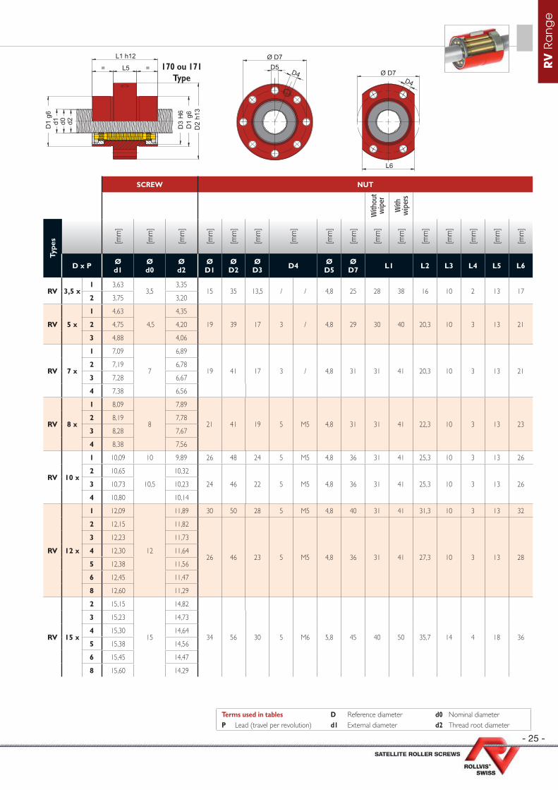
SCREW NUT
With
out
wip
er
With
w
iper
s
Type
s [mm
]
[mm
]
[mm
]
[mm
]
[mm
]
[mm
]
[mm
]
[mm
]
[mm
]
[mm
]
[mm
]
[mm
]
[mm
]
[mm
]
[mm
]
[mm
]
D x P Ød1
Ød0
Ød2
ØD1
Ø D2
Ø D3 D4 Ø
D5Ø D7 L1 L2 L3 L4 L5 L6
RV 3,5 x1 3,63
3,53,35
15 35 13,5 / / 4,8 25 28 38 16 10 2 13 172 3,75 3,20
RV 5 x
1 4,63
4,5
4,35
19 39 17 3 / 4,8 29 30 40 20,3 10 3 13 212 4,75 4,20
3 4,88 4,06
RV 7 x
1 7,09
7
6,89
19 41 17 3 / 4,8 31 31 41 20,3 10 3 13 212 7,19 6,78
3 7,28 6,67
4 7,38 6,56
RV 8 x
1 8,09
8
7,89
21 41 19 5 M5 4,8 31 31 41 22,3 10 3 13 232 8,19 7,78
3 8,28 7,67
4 8,38 7,56
RV 10 x
1 10,09 10 9,89 26 48 24 5 M5 4,8 36 31 41 25,3 10 3 13 26
2 10,65
10,5
10,32
24 46 22 5 M5 4,8 36 31 41 25,3 10 3 13 263 10,73 10,23
4 10,80 10,14
RV 12 x
1 12,09
12
11,89 30 50 28 5 M5 4,8 40 31 41 31,3 10 3 13 32
2 12,15 11,82
26 46 23 5 M5 4,8 36 31 41 27,3 10 3 13 28
3 12,23 11,73
4 12,30 11,64
5 12,38 11,56
6 12,45 11,47
8 12,60 11,29
RV 15 x
2 15,15
15
14,82
34 56 30 5 M6 5,8 45 40 50 35,7 14 4 18 36
3 15,23 14,73
4 15,30 14,64
5 15,38 14,56
6 15,45 14,47
8 15,60 14,29
d2d1 d0 D3
H6
D1
g6
D1
g6
= L5 =
L1 h12
D2
h13
D5Ø D7
D4
L6
D4Ø D7
170 ou 171Type
Terms used in tables D Reference diameter d0 Nominal diameterP Lead (travel per revolution) d1 External diameter d2 Thread root diameter

- 26 -
RV
Ra
ng
e
TECHNICAL CHARACTERISTICS
SINGLE NUT DOUBLE NUT SPLIT NUT
Type
s [°] [kN
]
[kN
]
[N2/
3µm
]
Max
axi
al
back
lash
*
[kN
]
[kN
]
[N2/
3µm
]
[N]
[Nm
]
[kN
]
[kN
]
[N2/
3µm
]
[N]
[Nm
]
DIR
EC
T
effi
cien
cy
IND
IRE
CT
ef
fi ci
ency
D x P N Helix angle Ca C0a Fk Ca C0a Fk Fv Mv Ca C0a Fk Fv Mv
RV 18 x
2
5
2,03 31,7 75,8 76,5 0,02 31,7 75,8 114,7 803 0,15 17,5 37,9 48,2 803 0,15 0,82 0,77
3 3,04 35,0 76,1 61,8 0,02 35,0 76,1 92,7 722 0,15 19,3 38,0 38,9 722 0,15 0,86 0,83
4 4,05 37,5 76,3 53,2 0,02 37,5 76,3 79,8 645 0,15 20,6 38,1 33,5 645 0,15 0,88 0,86
5 5,05 39,0 74,9 46,9 0,03 39,0 74,9 70,4 564 0,15 21,5 37,4 29,6 564 0,15 0,89 0,87
6 6,06 38,7 69,7 40,6 0,04 38,7 69,7 61,0 490 0,15 21,3 34,9 25,6 490 0,15 0,89 0,88
8 8,05 40,2 67,2 34,5 0,05 40,2 67,2 51,7 361 0,15 40,2 33,6 21,7 361 0,15 0,89 0,87
10 10,03 42,7 69,1 31,2 0,05 42,7 69,1 46,8 260 0,15 23,5 34,5 19,6 260 0,15 0,88 0,86
RV 20 x
2
5
1,87 39,1 102,1 87,8 0,02 39,1 102,1 131,7 1002 0,20 21,5 51,1 55,3 1 002 0,20 0,81 0,76
3 2,80 42,7 100,6 70,1 0,02 42,7 100,6 105,1 911 0,20 23,5 50,3 44,1 911 0,20 0,85 0,82
4 3,74 45,7 100,8 60,4 0,02 45,7 100,8 90,6 821 0,20 25,2 50,4 38,1 821 0,20 0,87 0,85
5 4,67 48,0 100,2 53,5 0,03 48,0 100,2 80,3 733 0,20 26,4 50,1 33,7 733 0,20 0,88 0,87
6 5,59 50,3 101,3 49,0 0,04 50,3 101,3 73,5 645 0,20 27,7 50,7 30,9 645 0,20 0,89 0,88
8 7,44 49,3 89,3 39,2 0,05 49,3 89,3 58,8 492 0,20 27,2 44,7 24,7 492 0,20 0,89 0,88
10 9,27 51,2 88,1 34,7 0,05 51,2 88,1 52,1 364 0,20 28,2 44,1 21,9 364 0,20 0,88 0,87
RV 21 x
2
5
1,74 48,4 106,9 89,2 0,02 48,4 106,9 133,7 1175 0,25 26,7 53,4 56,2 1 175 0,25 0,80 0,74
3 2,60 52,9 105,3 70,9 0,02 52,9 105,3 106,4 1082 0,25 29,1 52,6 44,7 1 082 0,25 0,84 0,81
4 3,47 56,7 105,5 61,3 0,02 56,7 105,5 91,9 983 0,25 31,2 52,8 38,6 983 0,25 0,87 0,85
5 4,33 59,4 104,8 54,2 0,03 59,4 104,8 81,3 886 0,25 32,7 52,4 34,2 886 0,25 0,88 0,86
6 5,20 62,4 106,0 49,6 0,03 62,4 106,0 74,4 791 0,25 34,4 53,0 31,2 791 0,25 0,89 0,87
8 6,91 61,2 93,5 39,7 0,04 61,2 93,5 59,6 619 0,25 33,7 46,7 25,0 619 0,25 0,89 0,88
10 8,62 63,5 92,2 35,1 0,05 63,5 92,2 52,7 472 0,25 35,0 46,1 22,1 472 0,25 0,89 0,87
RV 23 x
2
5
1,62 50,8 111,4 90,4 0,02 50,8 111,4 135,6 1330 0,30 28,0 55,7 57,0 1 330 0,30 0,79 0,73
3 2,43 55,5 109,7 71,8 0,02 55,5 109,7 107,7 1230 0,30 30,6 54,8 45,2 1 230 0,30 0,84 0,80
4 3,24 59,5 109,9 62,1 0,02 59,5 109,9 93,1 1130 0,30 32,8 55,0 39,1 1 130 0,30 0,86 0,84
5 4,05 62,4 109,2 54,9 0,03 62,4 109,2 82,4 1028 0,30 34,4 54,6 34,6 1 028 0,30 0,88 0,86
6 4,85 65,5 110,5 50,2 0,03 65,5 110,5 75,3 928 0,30 36,1 55,3 31,6 928 0,30 0,88 0,87
8 6,46 68,5 107,1 42,8 0,04 68,5 107,1 64,2 741 0,30 37,7 53,6 27,0 741 0,30 0,89 0,88
10 8,05 66,8 96,1 35,6 0,05 66,8 96,1 53,4 580 0,30 36,8 48,1 22,4 580 0,30 0,89 0,87
* Axial backlash can be reduced on demand.
RV Range - Satellite roller screws
= =
= =
d2d1 d0
D4
L3
L1 h12
L4 h
9
D3
H6
D1
g6L2
d2d1 d0 D3
H6
D1
g6D
2 h1
3
L5
L1 h12110 ou 111
Type160 ou 161
Type
Terms used in tables N Number of starts Fk Rigidity factorP Lead (travel per revolution) Ca Dynamic load capacity Fv Preloading forceD Reference diameter C0a Static load capacity Mv Preload torque

- 27 -
RV
Ra
ng
e
SCREW NUT
With
out
wip
er
With
w
iper
s
Type
s [mm
]
[mm
]
[mm
]
[mm
]
[mm
]
[mm
]
[mm
]
[mm
]
[mm
]
[mm
]
[mm
]
[mm
]
[mm
]
[mm
]
[mm
]
[mm
]
D x P Ød1
Ød0
Ød2
ØD1
Ø D2
Ø D3 D4 Ø
D5Ø D7 L1 L2 L3 L4 L5 L6
RV 18 x
2 18,15
18
17,82
40 62 35 5 M6 5,8 51 48 58 41,7 18 4 18 42
3 18,23 17,73
4 18,30 17,64
5 18,38 17,56
6 18,45 17,47
8 18,60 17,29
10 18,75 17,11
RV 20 x
2 19,65
19,5
19,32
42 64 39 5 M6 5,8 53 55 65 43,7 20 4 20 44
3 19,73 19,23
4 19,80 19,14
5 19,88 19,06
6 19,95 18,97
8 20,10 18,79
10 20,25 18,61
RV 21 x
2 21,15
21
20,82
45 67 41 5 M6 5,8 56 55 65 47 20 5 18 47
3 21,23 20,73
4 21,30 20,64
5 21,38 20,56
6 21,45 20,47
8 21,60 20,29
10 21,75 20,11
RV 23 x
2 22,65
22,5
22,32
45 68 42 5 M6 7,0 56 55 65 46,7 20 4 20 47
3 22,73 22,23
4 22,80 22,14
5 22,88 22,06
6 22,95 21,97
8 23,10 21,79
10 23,25 21,61
d2d1 d0 D3
H6
D1
g6
D1
g6
= L5 =
L1 h12
D2
h13
D5Ø D7
D4
L6
D4Ø D7
170 ou 171Type
Terms used in tables D Reference diameter d0 Nominal diameterP Lead (travel per revolution) d1 External diameter d2 Thread root diameter
- 28 -
RV
Ra
ng
e
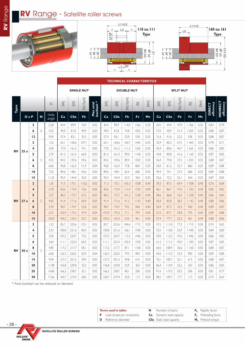
TECHNICAL CHARACTERISTICS
SINGLE NUT DOUBLE NUT SPLIT NUT
Type
s [°] [kN
]
[kN
]
[N2/
3µm
]
Max
axi
al
back
lash
*
[kN
]
[kN
]
[N2/
3µm
]
[N]
[Nm
]
[kN
]
[kN
]
[N2/
3µm
]
[N]
[Nm
]
DIR
EC
T
effi
cien
cy
IND
IRE
CT
ef
fi ci
ency
D x P N Helix angle Ca C0a Fk Ca C0a Fk Fv Mv Ca C0a Fk Fv Mv
RV 25 x
3
6
2,28 44,4 89,9 76,0 0,02 44,4 89,9 114,0 1366 0,35 24,5 44,9 47,9 1 366 0,35 0,83 0,79
6 4,55 49,0 81,8 49,9 0,03 49,0 81,8 74,8 1055 0,35 27,0 40,9 31,4 1 055 0,35 0,88 0,87
12 9,04 57,4 83,1 35,3 0,05 57,4 83,1 53,0 538 0,35 31,6 41,6 22,2 538 0,35 0,88 0,87
2
5
1,52 65,1 160,6 107,1 0,02 65,1 160,6 160,7 1465 0,35 35,9 80,3 67,5 1 465 0,35 0,78 0,71
4 3,04 77,0 161,2 74,1 0,02 77,0 161,2 111,2 1265 0,35 42,4 80,6 46,7 1 265 0,35 0,86 0,83
5 3,79 81,3 161,5 66,0 0,03 81,3 161,5 99,0 1160 0,35 44,8 80,8 41,6 1 160 0,35 0,87 0,85
6 4,55 84,2 159,6 59,6 0,03 84,2 159,6 89,4 1055 0,35 46,4 79,8 37,5 1 055 0,35 0,88 0,87
8 6,06 90,8 162,4 51,9 0,04 90,8 162,4 77,8 860 0,35 50,0 81,2 32,7 860 0,35 0,89 0,88
10 7,55 89,6 148,1 43,6 0,05 89,6 148,1 65,4 686 0,35 49,4 74,1 27,5 686 0,35 0,89 0,88
15 11,25 95,5 144,4 35,0 0,05 95,5 144,4 52,5 364 0,35 52,6 72,2 22,1 364 0,35 0,87 0,85
RV 27 x
2
5
1,35 71,3 175,1 110,2 0,02 71,3 175,1 165,3 1508 0,40 39,3 87,5 69,4 1 508 0,40 0,76 0,68
4 2,70 83,6 173,4 75,6 0,02 83,6 173,4 113,4 1332 0,40 46,1 86,7 47,6 1 332 0,40 0,85 0,82
5 3,37 88,3 173,7 67,5 0,03 88,3 173,7 101,2 1238 0,40 48,6 86,8 42,5 1 238 0,40 0,86 0,84
6 4,05 91,4 171,6 60,9 0,03 91,4 171,6 91,3 1143 0,40 50,4 85,8 38,3 1 143 0,40 0,88 0,86
8 5,39 98,7 174,7 52,8 0,03 98,7 174,7 79,2 960 0,40 54,4 87,3 33,3 960 0,40 0,89 0,87
10 6,72 103,9 175,3 47,4 0,04 103,9 175,3 71,1 793 0,40 57,2 87,7 29,8 793 0,40 0,89 0,88
15 10,03 104,2 155,4 35,7 0,05 104,2 155,4 53,5 461 0,40 57,4 77,7 22,5 461 0,40 0,88 0,86
RV 30 x
2
5
1,22 85,7 223,6 123,1 0,02 85,7 223,6 184,6 1715 0,50 47,2 111,8 77,5 1 715 0,50 0,74 0,65
4 2,43 100,8 221,6 84,0 0,02 100,8 221,6 126,1 1540 0,50 55,5 110,8 52,9 1 540 0,50 0,84 0,80
5 3,04 107,2 224,7 75,5 0,03 107,2 224,7 113,3 1446 0,50 59,0 112,3 47,6 1 446 0,50 0,86 0,83
6 3,64 111,1 222,4 68,3 0,03 111,1 222,4 102,4 1350 0,50 61,2 111,2 43,0 1 350 0,50 0,87 0,85
8 4,85 117,2 217,7 58,1 0,03 117,2 217,7 87,1 1160 0,50 64,6 108,9 36,6 1 160 0,50 0,88 0,87
10 6,06 126,3 226,5 52,9 0,04 126,3 226,5 79,3 983 0,50 69,6 113,3 33,3 983 0,50 0,89 0,88
15 9,04 127,3 201,5 39,9 0,05 127,3 201,5 59,8 615 0,50 70,1 100,7 25,1 615 0,50 0,88 0,87
20 11,98 156,8 229,8 35,2 0,05 156,8 229,8 52,9 363 0,50 86,4 114,9 22,2 363 0,50 0,86 0,83
25 14,86 166,2 238,7 32,1 0,05 166,2 238,7 48,1 206 0,50 91,6 119,3 20,2 206 0,50 0,81 0,77
30 17,66 160,7 219,4 28,0 0,05 160,7 219,4 42,0 113 0,50 88,5 109,7 17,7 113 0,50 0,74 0,64
* Axial backlash can be reduced on demand.
RV Range - Satellite roller screws
= =
= =
d2d1 d0
D4
L3
L1 h12
L4 h
9
D3
H6
D1
g6L2
d2d1 d0 D3
H6
D1
g6D
2 h1
3
L5
L1 h12110 ou 111
Type160 ou 161
Type
Terms used in tables N Number of starts Fk Rigidity factorP Lead (travel per revolution) Ca Dynamic load capacity Fv Preloading forceD Reference diameter C0a Static load capacity Mv Preload torque

- 29 -
RV
Ra
ng
e
SCREW NUT
With
out
wip
er
With
w
iper
s
Type
s [mm
]
[mm
]
[mm
]
[mm
]
[mm
]
[mm
]
[mm
]
[mm
]
[mm
]
[mm
]
[mm
]
[mm
]
[mm
]
[mm
]
[mm
]
[mm
]
D x P Ød1
Ød0
Ød2
ØD1
Ø D2
Ø D3 D4 Ø
D5Ø D7 L1 L2 L3 L4 L5 L6
RV 25 x
3 24,19
24
23,78
48 71 44 5 M6 7,0 59 48 58 49,7 18 4 20 506 24,38 23,56
12 24,75 23,11
2 24,15
24
23,82
53 84 48 5 M6 7,0 70 64 78 55,5 25 6 20 55
4 24,30 23,64
5 24,38 23,56
6 24,45 23,47
8 24,60 23,29
10 24,75 23,11
15 25,13 22,67
RV 27 x
2 27,15
27
26,82
53 83 50 5 M6 7,0 68 65 79 55,2 20 5 22 55
4 27,30 26,64
5 27,38 26,56
6 27,45 26,47
8 27,60 26,29
10 27,75 26,11
15 28,13 25,67
RV 30 x
2 30,15
30
29,82
62 92 58 5 M6 9,0 77 71 85 64,7 20 6 27 64
4 30,30 29,64
5 30,38 29,56
6 30,45 29,47
8 30,60 29,29
10 30,75 29,11
15 31,13 28,67
20 31,50 28,22
25 31,88 27,78
30 32,25 27,33
d2d1 d0 D3
H6
D1
g6
D1
g6
= L5 =
L1 h12
D2
h13
D5Ø D7
D4
L6
D4Ø D7
170 ou 171Type
Terms used in tables D Reference diameter d0 Nominal diameterP Lead (travel per revolution) d1 External diameter d2 Thread root diameter
- 30 -
RV
Ra
ng
e
TECHNICAL CHARACTERISTICS
SINGLE NUT DOUBLE NUT SPLIT NUT
Type
s [°] [kN
]
[kN
]
[N2/
3µm
]
Max
axi
al
back
lash
*
[kN
]
[kN
]
[N2/
3µm
]
[N]
[Nm
]
[kN
]
[kN
]
[N2/
3µm
]
[N]
[Nm
]
DIR
EC
T
effi
cien
cy
IND
IRE
CT
ef
fi ci
ency
D x P N Helix angle Ca C0a Fk Ca C0a Fk Fv Mv Ca C0a Fk Fv Mv
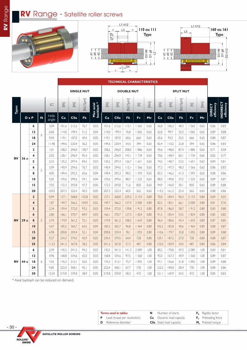
RV 36 x
6
6
3,04 101,6 212,6 76,7 0,03 101,6 212,6 115,1 1 565 0,65 56,0 106,3 48,3 1 565 0,65 0,86 0,83
12 6,06 114,0 199,4 51,2 0,04 114,0 199,4 76,8 1 065 0,65 62,8 99,7 32,3 1 065 0,65 0,89 0,88
18 9,04 119,1 187,0 40,4 0,05 119,1 187,0 60,6 666 0,65 65,6 93,5 25,5 666 0,65 0,88 0,87
24 11,98 149,6 220,4 36,2 0,05 149,6 220,4 54,3 394 0,65 82,4 110,2 22,8 394 0,65 0,86 0,83
2
5
1,01 108,2 296,0 138,7 0,02 108,2 296,0 208,0 1 886 0,65 59,6 148,0 87,4 1 886 0,65 0,71 0,58
4 2,03 128,1 296,9 95,4 0,02 128,1 296,9 143,1 1 734 0,65 70,6 148,4 60,1 1 734 0,65 0,82 0,77
5 2,53 135,2 297,4 84,5 0,03 135,2 297,4 126,7 1 651 0,65 74,5 148,7 53,2 1 651 0,65 0,84 0,81
6 3,04 140,4 294,6 76,7 0,03 140,4 294,6 115,1 1 566 0,65 77,3 147,3 48,3 1 566 0,65 0,86 0,83
8 4,05 149,4 292,3 65,6 0,04 149,4 292,3 98,5 1 393 0,65 82,3 146,2 41,3 1 393 0,65 0,88 0,86
10 5,05 159,6 299,6 59,1 0,04 159,6 299,6 88,7 1 225 0,65 88,0 149,8 37,2 1 225 0,65 0,89 0,87
15 7,55 172,3 293,8 47,7 0,05 172,3 293,8 71,6 850 0,65 94,9 146,9 30,1 850 0,65 0,89 0,88
20 10,03 207,3 322,4 40,3 0,05 207,3 322,4 60,5 562 0,65 114,2 161,2 25,4 562 0,65 0,88 0,86
RV 39 x
2
5
0,94 127,1 368,8 152,8 0,02 127,1 368,8 229,2 2 153 0,80 70,0 184,4 96,3 2 153 0,80 0,69 0,55
4 1,87 149,7 366,2 104,9 0,02 149,7 366,2 157,4 2 000 0,80 82,5 183,1 66,1 2 000 0,80 0,81 0,76
5 2,34 159,4 372,0 93,2 0,03 159,4 372,0 139,8 1 912 0,80 87,8 186,0 58,7 1 912 0,80 0,83 0,80
6 2,80 166,1 370,7 84,9 0,03 166,1 370,7 127,3 1 824 0,80 91,5 185,4 53,5 1 824 0,80 0,85 0,82
8 3,74 174,9 361,2 72,1 0,03 174,9 361,2 108,2 1 643 0,80 96,4 180,6 45,4 1 643 0,80 0,87 0,85
10 4,67 185,5 365,7 64,5 0,04 185,5 365,7 96,8 1 464 0,80 102,2 182,8 40,6 1 464 0,80 0,88 0,87
15 6,98 200,8 359,4 52,1 0,04 200,8 359,4 78,1 1 055 0,80 110,6 179,7 32,8 1 055 0,80 0,89 0,88
20 9,27 234,3 374,5 42,9 0,05 234,3 374,5 64,4 728 0,80 129,1 187,2 27,0 728 0,80 0,88 0,87
25 11,53 241,3 367,8 38,2 0,05 241,3 367,8 57,3 487 0,80 133,0 183,9 24,0 487 0,80 0,86 0,84
RV 44 x
6
6
2,49 145,5 341,5 94,2 0,03 145,5 341,5 141,3 2 089 1,00 80,2 170,8 59,3 2 089 1,00 0,84 0,81
12 4,96 168,8 334,6 65,0 0,03 168,8 334,6 97,5 1 560 1,00 93,0 167,3 40,9 1 560 1,00 0,89 0,87
18 7,42 176,3 313,1 50,5 0,05 176,3 313,1 75,7 1 092 1,00 97,1 156,6 31,8 1 092 1,00 0,89 0,88
24 9,85 222,4 368,1 45,1 0,05 222,4 368,1 67,7 730 1,00 122,5 184,0 28,4 730 1,00 0,88 0,86
30 12,24 219,8 339,8 38,9 0,05 219,8 339,8 58,3 472 1,00 121,1 169,9 24,5 472 1,00 0,85 0,83
* Axial backlash can be reduced on demand.
RV Range - Satellite roller screws
= =
= =
d2d1 d0
D4
L3
L1 h12
L4 h
9
D3
H6
D1
g6L2
d2d1 d0 D3
H6
D1
g6D
2 h1
3
L5
L1 h12110 ou 111
Type160 ou 161
Type
Terms used in tables N Number of starts Fk Rigidity factorP Lead (travel per revolution) Ca Dynamic load capacity Fv Preloading forceD Reference diameter C0a Static load capacity Mv Preload torque
- 31 -
RV
Ra
ng
e
SCREW NUT
With
out
wip
er
With
w
iper
s
Type
s [mm
]
[mm
]
[mm
]
[mm
]
[mm
]
[mm
]
[mm
]
[mm
]
[mm
]
[mm
]
[mm
]
[mm
]
[mm
]
[mm
]
[mm
]
[mm
]
D x P Ød1
Ød0
Ød2
ØD1
Ø D2
Ø D3 D4 Ø
D5Ø D7 L1 L2 L3 L4 L5 L6
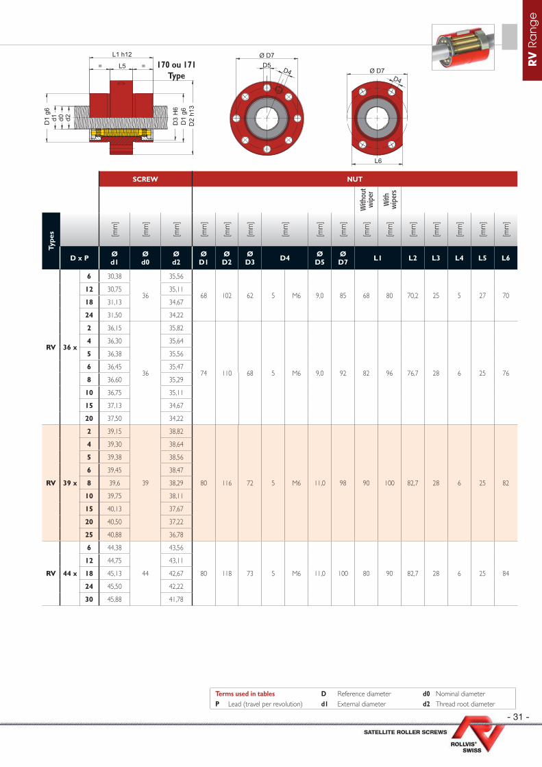
RV 36 x
6 30,38
36
35,56
68 102 62 5 M6 9,0 85 68 80 70,2 25 5 27 7012 30,75 35,11
18 31,13 34,67
24 31,50 34,22
2 36,15
36
35,82
74 110 68 5 M6 9,0 92 82 96 76,7 28 6 25 76
4 36,30 35,64
5 36,38 35,56
6 36,45 35,47
8 36,60 35,29
10 36,75 35,11
15 37,13 34,67
20 37,50 34,22
RV 39 x
2 39,15
39
38,82
80 116 72 5 M6 11,0 98 90 100 82,7 28 6 25 82
4 39,30 38,64
5 39,38 38,56
6 39,45 38,47
8 39,6 38,29
10 39,75 38,11
15 40,13 37,67
20 40,50 37,22
25 40,88 36,78
RV 44 x
6 44,38
44
43,56
80 118 73 5 M6 11,0 100 80 90 82,7 28 6 25 84
12 44,75 43,11
18 45,13 42,67
24 45,50 42,22
30 45,88 41,78
d2d1 d0 D3
H6
D1
g6
D1
g6
= L5 =
L1 h12
D2
h13
D5Ø D7
D4
L6
D4Ø D7
170 ou 171Type
Terms used in tables D Reference diameter d0 Nominal diameterP Lead (travel per revolution) d1 External diameter d2 Thread root diameter
- 32 -
RV
Ra
ng
e
TECHNICAL CHARACTERISTICS
SINGLE NUT DOUBLE NUT SPLIT NUT
Type
s [°] [kN
]
[kN
]
[N2/
3µm
]
Max
axi
al
back
lash
*
[kN
]
[kN
]
[N2/
3µm
]
[N]
[Nm
]
[kN
]
[kN
]
[N2/
3µm
]
[N]
[Nm
]
DIR
EC
T
effi
cien
cy
IND
IRE
CT
ef
fi ci
ency
D x P N Helix angle Ca C0a Fk Ca C0a Fk Fv Mv Ca C0a Fk Fv Mv
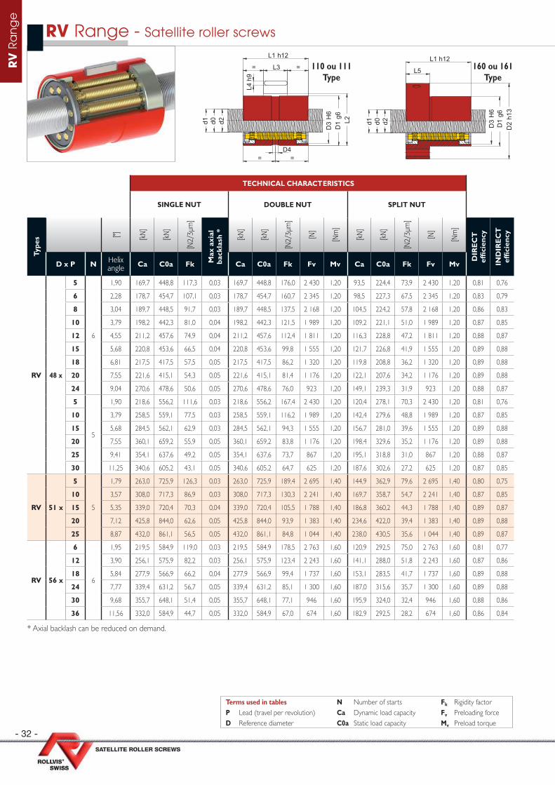
RV 48 x
5
6
1,90 169,7 448,8 117,3 0,03 169,7 448,8 176,0 2 430 1,20 93,5 224,4 73,9 2 430 1,20 0,81 0,76
6 2,28 178,7 454,7 107,1 0,03 178,7 454,7 160,7 2 345 1,20 98,5 227,3 67,5 2 345 1,20 0,83 0,79
8 3,04 189,7 448,5 91,7 0,03 189,7 448,5 137,5 2 168 1,20 104,5 224,2 57,8 2 168 1,20 0,86 0,83
10 3,79 198,2 442,3 81,0 0,04 198,2 442,3 121,5 1 989 1,20 109,2 221,1 51,0 1 989 1,20 0,87 0,85
12 4,55 211,2 457,6 74,9 0,04 211,2 457,6 112,4 1 811 1,20 116,3 228,8 47,2 1 811 1,20 0,88 0,87
15 5,68 220,8 453,6 66,5 0,04 220,8 453,6 99,8 1 555 1,20 121,7 226,8 41,9 1 555 1,20 0,89 0,88
18 6,81 217,5 417,5 57,5 0,05 217,5 417,5 86,2 1 320 1,20 119,8 208,8 36,2 1 320 1,20 0,89 0,88
20 7,55 221,6 415,1 54,3 0,05 221,6 415,1 81,4 1 176 1,20 122,1 207,6 34,2 1 176 1,20 0,89 0,88
24 9,04 270,6 478,6 50,6 0,05 270,6 478,6 76,0 923 1,20 149,1 239,3 31,9 923 1,20 0,88 0,87
5
5
1,90 218,6 556,2 111,6 0,03 218,6 556,2 167,4 2 430 1,20 120,4 278,1 70,3 2 430 1,20 0,81 0,76
10 3,79 258,5 559,1 77,5 0,03 258,5 559,1 116,2 1 989 1,20 142,4 279,6 48,8 1 989 1,20 0,87 0,85
15 5,68 284,5 562,1 62,9 0,03 284,5 562,1 94,3 1 555 1,20 156,7 281,0 39,6 1 555 1,20 0,89 0,88
20 7,55 360,1 659,2 55,9 0,05 360,1 659,2 83,8 1 176 1,20 198,4 329,6 35,2 1 176 1,20 0,89 0,88
25 9,41 354,1 637,6 49,2 0,05 354,1 637,6 73,7 867 1,20 195,1 318,8 31,0 867 1,20 0,88 0,87
30 11,25 340,6 605,2 43,1 0,05 340,6 605,2 64,7 625 1,20 187,6 302,6 27,2 625 1,20 0,87 0,85
RV 51 x
5
5
1,79 263,0 725,9 126,3 0,03 263,0 725,9 189,4 2 695 1,40 144,9 362,9 79,6 2 695 1,40 0,80 0,75
10 3,57 308,0 717,3 86,9 0,03 308,0 717,3 130,3 2 241 1,40 169,7 358,7 54,7 2 241 1,40 0,87 0,85
15 5,35 339,0 720,4 70,3 0,04 339,0 720,4 105,5 1 788 1,40 186,8 360,2 44,3 1 788 1,40 0,89 0,87
20 7,12 425,8 844,0 62,6 0,05 425,8 844,0 93,9 1 383 1,40 234,6 422,0 39,4 1 383 1,40 0,89 0,88
25 8,87 432,0 861,1 56,5 0,05 432,0 861,1 84,8 1 044 1,40 238,0 430,5 35,6 1 044 1,40 0,89 0,87
RV 56 x
6
6
1,95 219,5 584,9 119,0 0,03 219,5 584,9 178,5 2 763 1,60 120,9 292,5 75,0 2 763 1,60 0,81 0,77
12 3,90 256,1 575,9 82,2 0,03 256,1 575,9 123,4 2 243 1,60 141,1 288,0 51,8 2 243 1,60 0,87 0,86
18 5,84 277,9 566,9 66,2 0,04 277,9 566,9 99,4 1 737 1,60 153,1 283,5 41,7 1 737 1,60 0,89 0,88
24 7,77 339,4 631,2 56,7 0,05 339,4 631,2 85,1 1 300 1,60 187,0 315,6 35,7 1 300 1,60 0,89 0,88
30 9,68 355,7 648,1 51,4 0,05 355,7 648,1 77,1 946 1,60 195,9 324,0 32,4 946 1,60 0,88 0,86
36 11,56 332,0 584,9 44,7 0,05 332,0 584,9 67,0 674 1,60 182,9 292,5 28,2 674 1,60 0,86 0,84
* Axial backlash can be reduced on demand.
RV Range - Satellite roller screws
= =
= =
d2d1 d0
D4
L3
L1 h12
L4 h
9
D3
H6
D1
g6L2
d2d1 d0 D3
H6
D1
g6D
2 h1
3
L5
L1 h12110 ou 111
Type160 ou 161
Type
Terms used in tables N Number of starts Fk Rigidity factorP Lead (travel per revolution) Ca Dynamic load capacity Fv Preloading forceD Reference diameter C0a Static load capacity Mv Preload torque
- 33 -
RV
Ra
ng
e
SCREW NUT
With
out
wip
er
With
w
iper
s
Type
s [mm
]
[mm
]
[mm
]
[mm
]
[mm
]
[mm
]
[mm
]
[mm
]
[mm
]
[mm
]
[mm
]
[mm
]
[mm
]
[mm
]
[mm
]
[mm
]
D x P Ød1
Ød0
Ød2
ØD1
Ø D2
Ø D3 D4 Ø
D5Ø D7 L1 L2 L3 L4 L5 L6
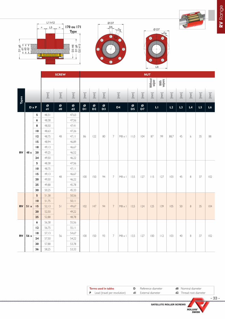
RV 48 x
5 48,31
48
47,63
86 122 80 7 M8 x 1 11,0 104 87 99 88,7 45 6 35 88
6 48,38 47,56
8 48,50 47,41
10 48,63 47,26
12 48,75 47,11
15 48,94 46,89
18 49,13 46,67
20 49,25 46,52
24 49,50 46,22
5 48,38
48
47,56
100 150 94 7 M8 x 1 13,5 127 115 127 103 45 8 37 102
10 48,75 47,11
15 49,13 46,67
20 49,50 46,22
25 49,88 45,78
30 50,25 45,33
RV 51 x
5 51,38
51
50,56
102 147 94 7 M8 x 1 13,5 124 125 139 105 50 8 35 104
10 51,75 50,11
15 52,13 49,67
20 52,50 49,22
25 52,88 48,78
RV 56 x
6 56,38
56
55,56
100 150 93 7 M8 x 1 13,5 127 100 112 103 40 8 37 102
12 56,75 55,11
18 57,13 54,67
24 57,50 54,22
30 57,88 53,78
36 58,25 53,33
d2d1 d0 D3
H6
D1
g6
D1
g6
= L5 =
L1 h12
D2
h13
D5Ø D7
D4
L6
D4Ø D7
170 ou 171Type
Terms used in tables D Reference diameter d0 Nominal diameterP Lead (travel per revolution) d1 External diameter d2 Thread root diameter

- 34 -
RV
Ra
ng
e
TECHNICAL CHARACTERISTICS
SINGLE NUT DOUBLE NUT SPLIT NUT
Type
s [°] [kN
]
[kN
]
[N2/
3µm
]
Max
axi
al
back
lash
*
[kN
]
[kN
]
[N2/
3µm
]
[N]
[Nm
]
[kN
]
[kN
]
[N2/
3µm
]
[N]
[Nm
]
DIR
EC
T
effi
cien
cy
IND
IRE
CT
ef
fi ci
ency
D x P N Helix angle Ca C0a Fk Ca C0a Fk Fv Mv Ca C0a Fk Fv Mv
RV 60 x
6
6
1,82 248,5 689,4 128,2 0,04 248,5 689,4 192,4 2 936 1,80 136,9 344,7 80,8 2 936 1,80 0,80 0,75
10 3,04 277,8 678,4 97,2 0,04 277,8 678,4 145,9 2 601 1,80 153,1 339,2 61,3 2 601 1,80 0,86 0,83
12 3,64 290,3 679,7 88,3 0,04 290,3 679,7 132,5 2 429 1,80 159,9 339,8 55,6 2 429 1,80 0,87 0,85
18 5,45 315,6 669,9 71,2 0,04 315,6 669,9 106,7 1 926 1,80 173,9 335,0 44,8 1 926 1,80 0,89 0,87
20 6,06 327,4 684,4 68,2 0,04 327,4 684,4 102,3 1 769 1,80 180,4 342,2 43,0 1 769 1,80 0,89 0,88
30 9,04 393,2 747,8 54,6 0,07 393,2 747,8 81,8 1 108 1,80 216,6 373,9 34,4 1 108 1,80 0,88 0,87
42 12,56 393,0 755,2 46,4 0,07 393,0 755,2 69,6 586 1,80 216,5 377,6 29,3 586 1,80 0,85 0,82
5
5
1,52 340,4 1 005,9 147,9 0,04 340,4 1005,9 221,8 3 014 1,80 187,5 502,9 93,1 3 014 1,80 0,78 0,71
10 3,04 380,1 925,8 96,5 0,04 380,1 925,8 144,8 2 601 1,80 209,4 462,9 60,8 2 601 1,80 0,86 0,83
15 4,55 415,0 915,9 77,5 0,04 415,0 915,9 116,3 2 173 1,80 228,6 458,0 48,9 2 173 1,80 0,88 0,87
20 6,06 500,4 1 057,1 68,4 0,04 500,4 1057,1 102,6 1 769 1,80 275,7 528,5 43,1 1 769 1,80 0,89 0,88
25 7,55 494,0 1 029,9 60,2 0,05 494,0 1029,9 90,3 1 412 1,80 272,2 515,0 37,9 1 412 1,80 0,89 0,88
30 9,04 495,5 1 034,1 55,1 0,07 495,5 1034,1 82,6 1 108 1,80 273,0 517,1 34,7 1 108 1,80 0,88 0,87
35 10,52 470,0 958,1 48,4 0,07 470,0 958,1 72,5 857 1,80 258,9 479,0 30,5 857 1,80 0,87 0,85
RV 64 x
6
6
1,71 255,5 802,2 137,3 0,04 255,5 802,2 206,0 3 089 2,00 142,7 401,1 86,5 3 089 2,00 0,79 0,74
12 3,42 303,1 791,8 94,5 0,04 303,1 791,8 141,8 2 598 2,00 169,3 395,9 59,5 2 598 2,00 0,87 0,84
18 5,12 332,8 781,4 76,0 0,04 332,8 781,4 114,0 2 101 2,00 185,9 390,7 47,9 2 101 2,00 0,89 0,87
24 6,81 428,8 932,6 68,2 0,04 428,8 932,6 102,3 1 650 2,00 239,6 466,3 42,9 1 650 2,00 0,89 0,88
30 8,49 408,9 854,6 57,7 0,06 408,9 854,6 86,6 1 266 2,00 228,4 427,3 36,4 1 266 2,00 0,89 0,87
36 10,15 397,3 812,6 51,4 0,07 397,3 812,6 77,2 953 2,00 221,9 406,3 32,4 953 2,00 0,88 0,86
RV 70 x
6
6
1,59 321,2 1 120,0 160,5 0,04 - - - - - - - - - - 0,78 0,72
12 3,17 381,9 1 108,2 110,5 0,04 - - - - - - - - - - 0,86 0,84
18 4,75 420,4 1 096,4 89,0 0,04 - - - - - - - - - - 0,88 0,87
24 6,32 525,1 1 265,4 78,4 0,04 - - - - - - - - - - 0,89 0,88
30 7,88 518,6 1 230,5 68,4 0,05 - - - - - - - - - - 0,89 0,88
36 9,43 498,8 1 149,4 60,3 0,07 - - - - - - - - - - 0,88 0,87
* Axial backlash can be reduced on demand.
RV Range - Satellite roller screws
= =
= =
d2d1 d0
D4
L3
L1 h12
L4 h
9
D3
H6
D1
g6L2
d2d1 d0 D3
H6
D1
g6D
2 h1
3
L5
L1 h12110 ou 111
Type160 ou 161
Type
Terms used in tables N Number of starts Fk Rigidity factorP Lead (travel per revolution) Ca Dynamic load capacity Fv Preloading forceD Reference diameter C0a Static load capacity Mv Preload torque

- 35 -
RV
Ra
ng
e
SCREW NUT
With
out
wip
er
With
w
iper
s
Type
s [mm
]
[mm
]
[mm
]
[mm
]
[mm
]
[mm
]
[mm
]
[mm
]
[mm
]
[mm
]
[mm
]
[mm
]
[mm
]
[mm
]
[mm
]
[mm
]
D x P Ød1
Ød0
Ød2
ØD1
Ø D2
Ø D3 D4 Ø
D5Ø D7 L1 L2 L3 L4 L5 L6
RV 60 x
6 60,38
60
59,56
110 150 100 10,5 M8 x 1 13,5 130 106 124 113,2 40 8 30 112
10 60,63 59,26
12 60,75 59,11
18 61,13 58,67
20 61,25 58,52
30 61,88 57,78
42 62,63 56,89
5 60,38
60
59,56
122 180 110 10,5 M8 x 1 17,5 150 140 152 125,7 45 10 40 124
10 60,75 59,11
15 61,13 58,67
20 61,50 58,22
25 61,88 57,78
30 62,25 57,33
35 62,63 56,89
RV 64 x
6 64,38
64
63,56
115 180 106 7 M8 x 1 17,5 150 118 129 118 45 8 40 117
12 64,75 63,11
18 65,13 62,67
24 65,50 62,22
30 65,88 61,78
36 66,25 61,33
RV 70 x
6 69,38
69
68,56
130 172 115 9 M8 x 1 13,5 152 140 170 133,7 50 10 45 132
12 69,75 68,11
18 70,13 67,67
24 70,50 67,22
30 70,88 66,78
36 71,25 66,33
d2d1 d0 D3
H6
D1
g6
D1
g6
= L5 =
L1 h12
D2
h13
D5Ø D7
D4
L6
D4Ø D7
170 ou 171Type
Terms used in tables D Reference diameter d0 Nominal diameterP Lead (travel per revolution) d1 External diameter d2 Thread root diameter
- 36 -
RV
Ra
ng
e
TECHNICAL CHARACTERISTICS
SINGLE NUT DOUBLE NUT SPLIT NUT
Type
s [°] [kN
]
[kN
]
[N2/
3µm
]
Max
axi
al
back
lash
*
[kN
]
[kN
]
[N2/
3µm
]
[N]
[Nm
]
[kN
]
[kN
]
[N2/
3µm
]
[N]
[Nm
]
DIR
EC
T
effi
cien
cy
IND
IRE
CT
ef
fi ci
ency
D x P N Helix angle Ca C0a Fk Ca C0a Fk Fv Mv Ca C0a Fk Fv Mv
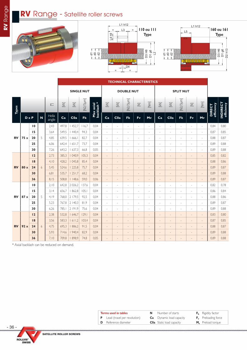
RV 75 x
10
5
2,43 497,8 1 452,7 116,7 0,04 - - - - - - - - - - 0,84 0,80
15 3,64 549,5 1 440,4 94,3 0,04 - - - - - - - - - - 0,87 0,85
20 4,85 639,5 1 666,1 82,7 0,04 - - - - - - - - - - 0,88 0,87
25 6,06 642,4 1 651,7 73,7 0,04 - - - - - - - - - - 0,89 0,88
30 7,26 643,2 1 637,3 66,8 0,05 - - - - - - - - - - 0,89 0,88
RV 80 x
12
6
2,73 385,3 1 040,9 105,3 0,04 - - - - - - - - - - 0,85 0,82
18 4,10 428,2 1 045,8 85,4 0,04 - - - - - - - - - - 0,88 0,86
24 5,45 524,6 1 225,8 75,7 0,04 - - - - - - - - - - 0,89 0,87
30 6,81 535,7 1 251,7 68,2 0,04 - - - - - - - - - - 0,89 0,88
36 8,15 508,8 1 148,6 59,0 0,06 - - - - - - - - - - 0,89 0,87
RV 87 x
10
5
2,10 642,8 2 026,2 137,6 0,04 - - - - - - - - - - 0,82 0,78
15 3,14 656,7 1 862,8 105,1 0,04 - - - - - - - - - - 0,86 0,84
20 4,19 768,0 2 179,5 92,5 0,04 - - - - - - - - - - 0,88 0,86
25 5,23 767,8 2 140,3 81,9 0,04 - - - - - - - - - - 0,89 0,87
30 6,26 785,1 2 191,9 75,6 0,04 - - - - - - - - - - 0,89 0,88
RV 92 x
12
6
2,38 532,8 1 646,7 129,1 0,04 - - - - - - - - - - 0,83 0,80
18 3,56 583,3 1 611,2 103,4 0,04 - - - - - - - - - - 0,87 0,85
24 4,75 695,3 1 886,2 91,5 0,04 - - - - - - - - - - 0,88 0,87
30 5,93 714,6 1 940,4 82,9 0,04 - - - - - - - - - - 0,89 0,88
36 7,10 709,8 1 898,9 74,8 0,05 - - - - - - - - - - 0,89 0,88
* Axial backlash can be reduced on demand.
RV Range - Satellite roller screws
= =
= =
d2d1 d0
D4
L3
L1 h12
L4 h
9
D3
H6
D1
g6L2
d2d1 d0 D3
H6
D1
g6D
2 h1
3
L5
L1 h12110 ou 111
Type160 ou 161
Type
Terms used in tables N Number of starts Fk Rigidity factorP Lead (travel per revolution) Ca Dynamic load capacity Fv Preloading forceD Reference diameter C0a Static load capacity Mv Preload torque

- 37 -
RV
Ra
ng
e
SCREW NUT
With
out
wip
er
With
w
iper
s
Type
s [mm
]
[mm
]
[mm
]
[mm
]
[mm
]
[mm
]
[mm
]
[mm
]
[mm
]
[mm
]
[mm
]
[mm
]
[mm
]
[mm
]
[mm
]
[mm
]
D x P Ød1
Ød0
Ød2
ØD1
Ø D2
Ø D3 D4 Ø
D5Ø D7 L1 L2 L3 L4 L5 L6
RV 75 x
10 75,75
75
74,11
150 210 140 10,5 M8 x 1 17,5 180 175 191 153 63 10 45 152
15 76,13 73,67
20 76,50 73,22
25 76,88 72,78
30 77,25 72,33
RV 80 x
12 80,75
80
79,11
138 180 130 10,5 M8 x 1 13,5 160 130 158 141,7 50 10 35 140
18 81,13 78,67
24 81,50 78,22
30 81,88 77,78
36 82,25 77,33
RV 87 x
10 87,75
87
86,11
175 235 162 10,5 M8 x 1 17,5 200 190 215 178 63 10 45 177
15 88,13 85,67
20 88,50 85,22
25 88,88 84,78
30 89,25 84,33
RV 92 x
12 92,75
92
91,11
160 220 146 10,5 M8 x 1 17,5 190 155 179 163 63 10 45 162
18 93,13 90,67
24 93,50 90,22
30 93,88 89,78
36 94,25 89,33
d2d1 d0 D3
H6
D1
g6
D1
g6
= L5 =
L1 h12
D2
h13
D5Ø D7
D4
L6
D4Ø D7
170 ou 171Type
Terms used in tables D Reference diameter d0 Nominal diameterP Lead (travel per revolution) d1 External diameter d2 Thread root diameter

- 38 -
RV
Ra
ng
e
TECHNICAL CHARACTERISTICS
SINGLE NUT DOUBLE NUT SPLIT NUT
Type
s [°] [kN
]
[kN
]
[N2/
3µm
]
Max
axi
al
back
lash
*
[kN
]
[kN
]
[N2/
3µm
]
[N]
[Nm
]
[kN
]
[kN
]
[N2/
3µm
]
[N]
[Nm
]
DIR
EC
T
effi
cien
cy
IND
IRE
CT
ef
fi ci
ency
D x P N Helix angle Ca C0a Fk Ca C0a Fk Fv Mv Ca C0a Fk Fv Mv
RV 100 x
12
6
2,19 790,2 2 649,7 153,2 0,05 - - - - - - - - - - 0,82 0,79
18 3,28 843,7 2 603,3 123,0 0,05 - - - - - - - - - - 0,86 0,84
24 4,37 858,2 2 610,2 106,0 0,05 - - - - - - - - - - 0,88 0,86
30 5,45 857,8 2 563,9 94,0 0,05 - - - - - - - - - - 0,89 0,87
15
5
2,76 1 044,9 3 598,6 135,4 0,05 - - - - - - - - - - 0,85 0,82
20 3,68 1 063,3 3 605,5 116,4 0,05 - - - - - - - - - - 0,87 0,85
25 4,60 1 077,2 3 612,3 103,8 0,05 - - - - - - - - - - 0,88 0,87
30 5,51 1 088,0 3 619,1 95,0 0,05 - - - - - - - - - - 0,89 0,87
35 6,42 1 106,7 3 679,6 88,6 0,05 - - - - - - - - - - 0,89 0,88
RV 120 x
18
6
2,73 1 063,2 3 667,3 142,3 0,05 - - - - - - - - - - 0,85 0,82
24 3,64 1 082,0 3 675,6 122,6 0,05 - - - - - - - - - - 0,87 0,85
30 4,55 1 090,3 3 652,0 108,8 0,05 - - - - - - - - - - 0,88 0,87
36 5,45 1 107,2 3 692,0 99,9 0,05 - - - - - - - - - - 0,89 0,87
15
5
2,28 1 252,5 4 634,6 151,7 0,05 - - - - - - - - - - 0,83 0,79
20 3,04 1 214,1 4 320,3 124,4 0,05 - - - - - - - - - - 0,86 0,83
25 3,79 1 214,0 4 234,2 109,5 0,05 - - - - - - - - - - 0,87 0,85
30 4,55 1 232,5 4 274,3 100,0 0,05 - - - - - - - - - - 0,88 0,87
35 5,30 1 220,6 4 157,0 91,4 0,05 - - - - - - - - - - 0,89 0,87
* Axial backlash can be reduced on demand.
RV Range - Satellite roller screws
= =
= =
d2d1 d0
D4
L3
L1 h12
L4 h
9
D3
H6
D1
g6L2
d2d1 d0 D3
H6
D1
g6D
2 h1
3
L5
L1 h12110 ou 111
Type160 ou 161
Type
Terms used in tables N Number of starts Fk Rigidity factorP Lead (travel per revolution) Ca Dynamic load capacity Fv Preloading forceD Reference diameter C0a Static load capacity Mv Preload torque
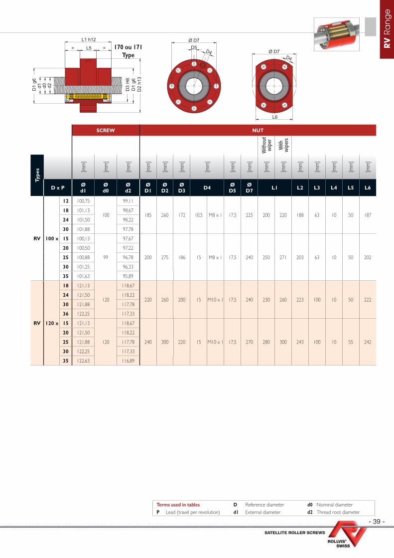
- 39 -
RV
Ra
ng
e
SCREW NUT
With
out
wip
er
With
w
iper
s
Type
s [mm
]
[mm
]
[mm
]
[mm
]
[mm
]
[mm
]
[mm
]
[mm
]
[mm
]
[mm
]
[mm
]
[mm
]
[mm
]
[mm
]
[mm
]
[mm
]
D x P Ød1
Ød0
Ød2
ØD1
Ø D2
Ø D3 D4 Ø
D5Ø D7 L1 L2 L3 L4 L5 L6
RV 100 x
12 100,75
100
99,11
185 260 172 10,5 M8 x 1 17,5 225 200 220 188 63 10 50 18718 101,13 98,67
24 101,50 98,22
30 101,88 97,78
15 100,13
99
97,67
200 275 186 15 M8 x 1 17,5 240 250 271 203 63 10 50 202
20 100,50 97,22
25 100,88 96,78
30 101,25 96,33
35 101,63 95,89
RV 120 x
18 121,13
120
118,67
220 260 200 15 M10 x 1 17,5 240 230 260 223 100 10 50 22224 121,50 118,22
30 121,88 117,78
36 122,25 117,33
15 121,13
120
118,67
240 300 220 15 M10 x 1 17,5 270 280 300 243 100 10 55 242
20 121,50 118,22
25 121,88 117,78
30 122,25 117,33
35 122,63 116,89
d2d1 d0 D3
H6
D1
g6
D1
g6
= L5 =
L1 h12
D2
h13
D5Ø D7
D4
L6
D4Ø D7
170 ou 171Type
Terms used in tables D Reference diameter d0 Nominal diameterP Lead (travel per revolution) d1 External diameter d2 Thread root diameter
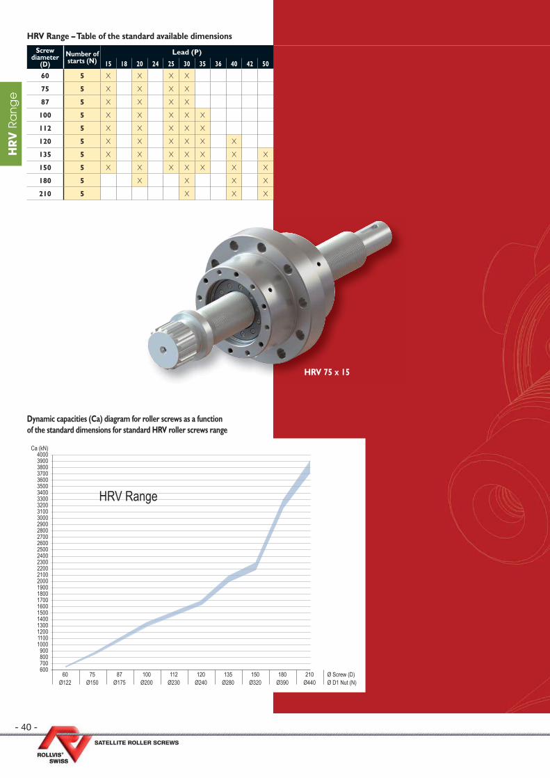
- 40 -
HR
V R
an
ge
Screw diameter
(D)Number of starts (N)
Lead (P)
15 18 20 24 25 30 35 36 40 42 50
60 5 X X X X
75 5 X X X X
87 5 X X X X
100 5 X X X X X
112 5 X X X X X
120 5 X X X X X X
135 5 X X X X X X X
150 5 X X X X X X X
180 5 X X X X
210 5 X X X
HRV Range – Table of the standard available dimensions
HRV 75 x 15
Dynamic capacities (Ca) diagram for roller screws as a function of the standard dimensions for standard HRV roller screws range
210Ø440
180Ø390
150Ø320
135Ø280
120Ø240
112Ø230
100Ø200
87Ø175
75Ø150
60Ø122
Ø Screw (D)Ø D1 Nut (N)
4000390038003700360035003400330032003100300029002800270026002500240023002200210020001900180017001600150014001300120011001000
900800700600
Ca (kN)
HRV Range
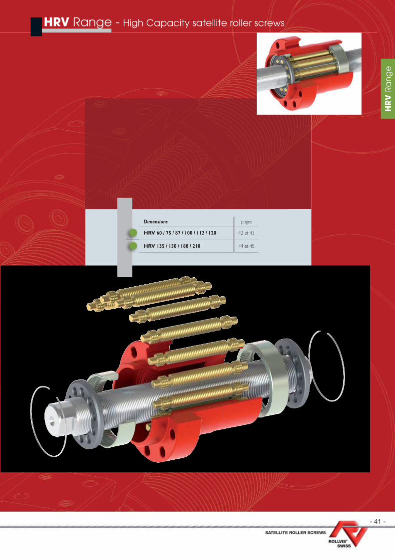
- 41 -
HR
V R
an
ge
HRV Range - High Capacity satellite roller screws
Dimensions pages
HRV 60 / 75 / 87 / 100 / 112 / 120 42 et 43
HRV 135 / 150 / 180 / 210 44 et 45
HR
V R
an
ge
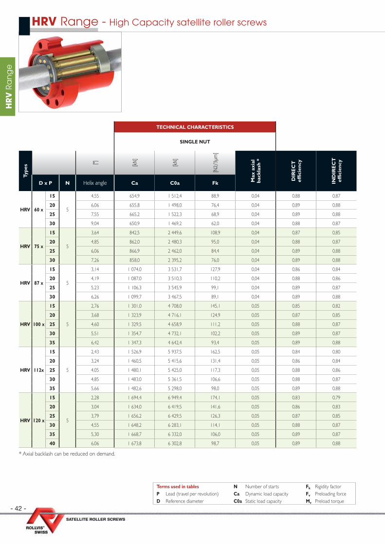
- 42 -
HR
V R
an
ge
TECHNICAL CHARACTERISTICS
SINGLE NUT
Type
s [°] [kN
]
[kN
]
[N2/
3µm
]
Max
axi
al
back
lash
*
DIR
EC
T
effi
cien
cy
IND
IRE
CT
ef
fi ci
ency
D x P N Helix angle Ca C0a Fk
HRV 60 x
15
5
4,55 654,9 1 512,4 88,9 0,04 0,88 0,87
20 6,06 655,8 1 498,0 76,4 0,04 0,89 0,88
25 7,55 665,2 1 522,3 68,9 0,04 0,89 0,88
30 9,04 650,9 1 469,2 62,0 0,04 0,88 0,87
HRV 75 x
15
5
3,64 842,5 2 449,6 108,9 0,04 0,87 0,85
20 4,85 862,0 2 480,3 95,0 0,04 0,88 0,87
25 6,06 866,9 2 462,0 84,4 0,04 0,89 0,88
30 7,26 858,0 2 395,2 76,0 0,04 0,89 0,88
HRV 87 x
15
5
3,14 1 074,0 3 531,7 127,9 0,04 0,86 0,84
20 4,19 1 087,0 3 510,3 110,2 0,04 0,88 0,86
25 5,23 1 106,3 3 545,9 99,1 0,04 0,89 0,87
30 6,26 1 099,7 3 467,5 89,1 0,04 0,89 0,88
HRV 100 x
15
5
2,76 1 301,0 4 708,0 145,1 0,05 0,85 0,82
20 3,68 1 323,9 4 716,1 124,9 0,05 0,87 0,85
25 4,60 1 329,5 4 658,9 111,2 0,05 0,88 0,87
30 5,51 1 354,7 4 732,1 102,2 0,05 0,89 0,87
35 6,42 1 347,3 4 642,4 93,4 0,05 0,89 0,88
HRV 112x
15
5
2,43 1 526,9 5 937,5 162,5 0,05 0,84 0,80
20 3,24 1 460,5 5 415,6 131,4 0,05 0,86 0,84
25 4,05 1 480,1 5 425,0 117,3 0,05 0,88 0,86
30 4,85 1 483,0 5 361,5 106,6 0,05 0,88 0,87
35 5,66 1 482,6 5 298,0 98,0 0,05 0,89 0,88
HRV 120 x
15
5
2,28 1 694,4 6 949,4 174,1 0,05 0,83 0,79
20 3,04 1 634,0 6 419,5 141,6 0,05 0,86 0,83
25 3,79 1 656,2 6 429,5 126,3 0,05 0,87 0,85
30 4,55 1 648,2 6 283,1 114,1 0,05 0,88 0,87
35 5,30 1 668,7 6 332,0 106,0 0,05 0,89 0,87
40 6,06 1 673,8 6 302,8 98,7 0,05 0,89 0,88
* Axial backlash can be reduced on demand.
HRV Range - High Capacity satellite roller screws
Terms used in tables N Number of starts Fk Rigidity factorP Lead (travel per revolution) Ca Dynamic load capacity Fv Preloading forceD Reference diameter C0a Static load capacity Mv Preload torque
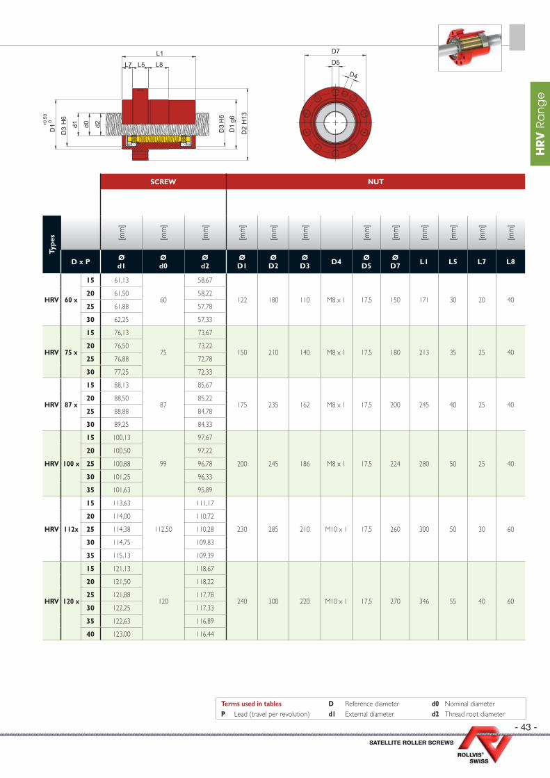
- 43 -
HR
V R
an
ge
SCREW NUT
Type
s [mm
]
[mm
]
[mm
]
[mm
]
[mm
]
[mm
]
[mm
]
[mm
]
[mm
]
[mm
]
[mm
]
[mm
]
D x P Ød1
Ød0
Ød2
ØD1
Ø D2
Ø D3 D4 Ø
D5Ø D7 L1 L5 L7 L8
HRV 60 x
15 61,13
60
58,67
122 180 110 M8 x 1 17,5 150 171 30 20 4020 61,50 58,22
25 61,88 57,78
30 62,25 57,33
HRV 75 x
15 76,13
75
73,67
150 210 140 M8 x 1 17,5 180 213 35 25 4020 76,50 73,22
25 76,88 72,78
30 77,25 72,33
HRV 87 x
15 88,13
87
85,67
175 235 162 M8 x 1 17,5 200 245 40 25 4020 88,50 85,22
25 88,88 84,78
30 89,25 84,33
HRV 100 x
15 100,13
99
97,67
200 245 186 M8 x 1 17,5 224 280 50 25 40
20 100,50 97,22
25 100,88 96,78
30 101,25 96,33
35 101,63 95,89
HRV 112x
15 113,63
112,50
111,17
230 285 210 M10 x 1 17,5 260 300 50 30 60
20 114,00 110,72
25 114,38 110,28
30 114,75 109,83
35 115,13 109,39
HRV 120 x
15 121,13
120
118,67
240 300 220 M10 x 1 17,5 270 346 55 40 60
20 121,50 118,22
25 121,88 117,78
30 122,25 117,33
35 122,63 116,89
40 123,00 116,44
Terms used in tables D Reference diameter d0 Nominal diameterP Lead (travel per revolution) d1 External diameter d2 Thread root diameter
d0 d2d1
D3
H6
D3
H6
D1
g6
D1 +0
.50
0
D2
H13
L1
L5L7 L8
D7
D5
D4
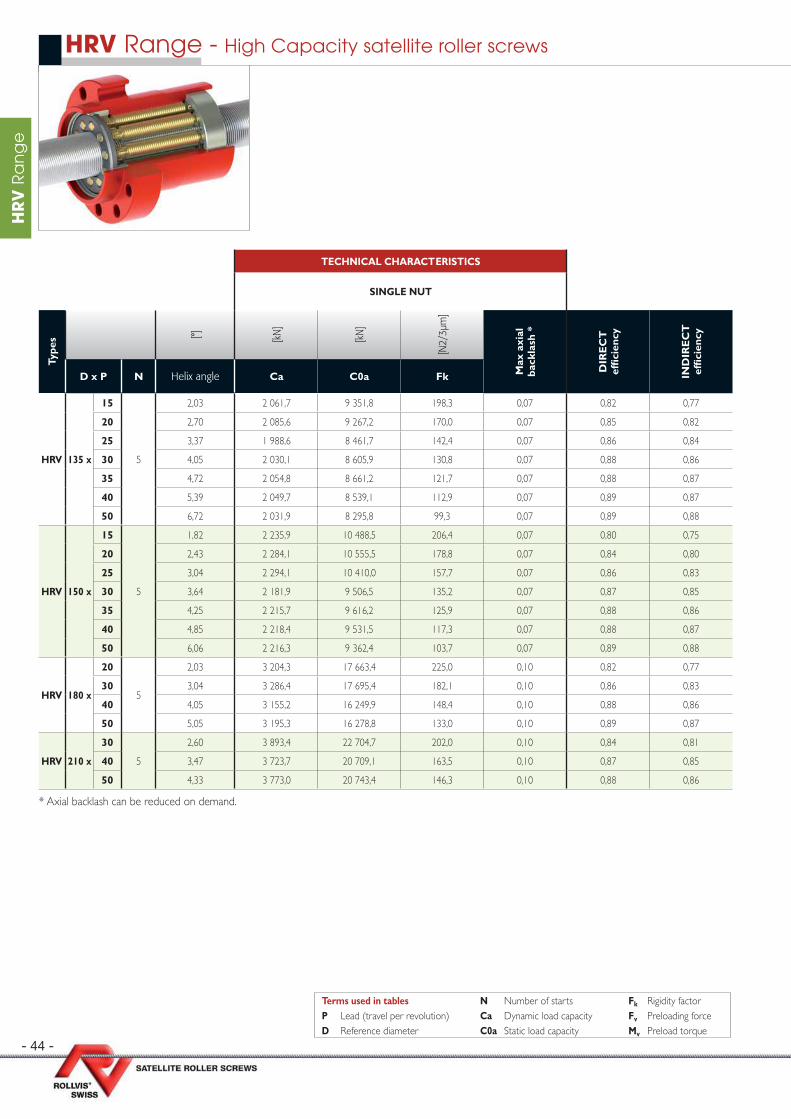
- 44 -
HR
V R
an
ge
TECHNICAL CHARACTERISTICS
SINGLE NUT
Type
s [°] [kN
]
[kN
]
[N2/
3µm
]
Max
axi
al
back
lash
*
DIR
EC
T
effi
cien
cy
IND
IRE
CT
ef
fi ci
ency
D x P N Helix angle Ca C0a Fk
HRV 135 x
15
5
2,03 2 061,7 9 351,8 198,3 0,07 0,82 0,77
20 2,70 2 085,6 9 267,2 170,0 0,07 0,85 0,82
25 3,37 1 988,6 8 461,7 142,4 0,07 0,86 0,84
30 4,05 2 030,1 8 605,9 130,8 0,07 0,88 0,86
35 4,72 2 054,8 8 661,2 121,7 0,07 0,88 0,87
40 5,39 2 049,7 8 539,1 112,9 0,07 0,89 0,87
50 6,72 2 031,9 8 295,8 99,3 0,07 0,89 0,88
HRV 150 x
15
5
1,82 2 235,9 10 488,5 206,4 0,07 0,80 0,75
20 2,43 2 284,1 10 555,5 178,8 0,07 0,84 0,80
25 3,04 2 294,1 10 410,0 157,7 0,07 0,86 0,83
30 3,64 2 181,9 9 506,5 135,2 0,07 0,87 0,85
35 4,25 2 215,7 9 616,2 125,9 0,07 0,88 0,86
40 4,85 2 218,4 9 531,5 117,3 0,07 0,88 0,87
50 6,06 2 216,3 9 362,4 103,7 0,07 0,89 0,88
HRV 180 x
20
5
2,03 3 204,3 17 663,4 225,0 0,10 0,82 0,77
30 3,04 3 286,4 17 695,4 182,1 0,10 0,86 0,83
40 4,05 3 155,2 16 249,9 148,4 0,10 0,88 0,86
50 5,05 3 195,3 16 278,8 133,0 0,10 0,89 0,87
HRV 210 x
30
5
2,60 3 893,4 22 704,7 202,0 0,10 0,84 0,81
40 3,47 3 723,7 20 709,1 163,5 0,10 0,87 0,85
50 4,33 3 773,0 20 743,4 146,3 0,10 0,88 0,86
* Axial backlash can be reduced on demand.
HRV Range - High Capacity satellite roller screws
Terms used in tables N Number of starts Fk Rigidity factorP Lead (travel per revolution) Ca Dynamic load capacity Fv Preloading forceD Reference diameter C0a Static load capacity Mv Preload torque
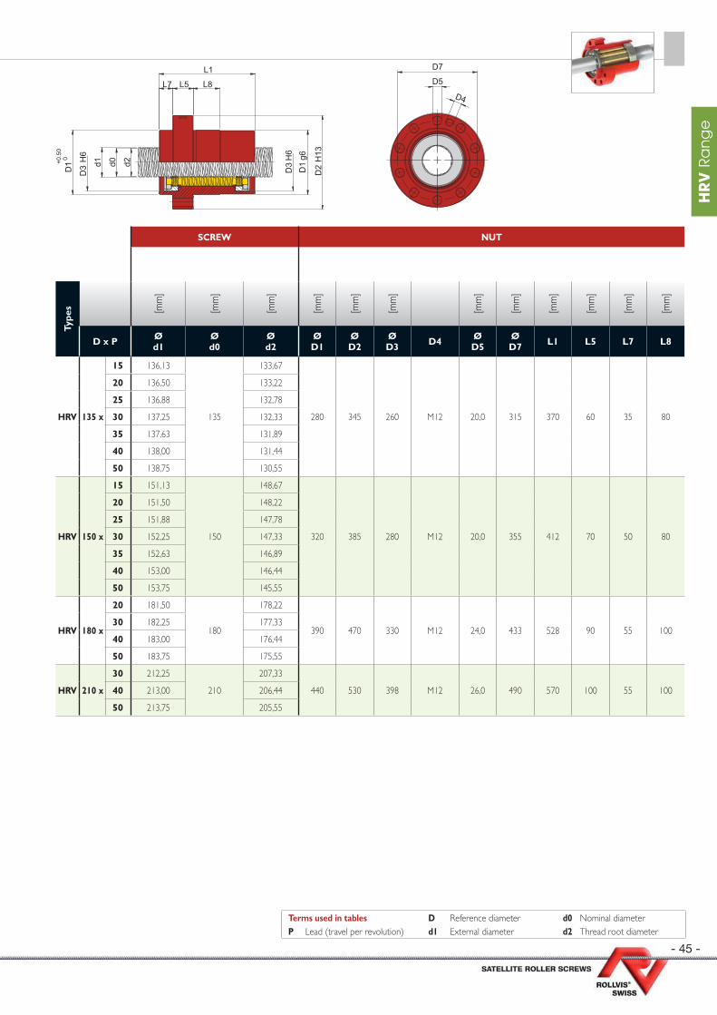
- 45 -
HR
V R
an
ge
SCREW NUT
Type
s [mm
]
[mm
]
[mm
]
[mm
]
[mm
]
[mm
]
[mm
]
[mm
]
[mm
]
[mm
]
[mm
]
[mm
]
D x P Ød1
Ød0
Ød2
ØD1
Ø D2
Ø D3 D4 Ø
D5Ø D7 L1 L5 L7 L8
HRV 135 x
15 136,13
135
133,67
280 345 260 M12 20,0 315 370 60 35 80
20 136,50 133,22
25 136,88 132,78
30 137,25 132,33
35 137,63 131,89
40 138,00 131,44
50 138,75 130,55
HRV 150 x
15 151,13
150
148,67
320 385 280 M12 20,0 355 412 70 50 80
20 151,50 148,22
25 151,88 147,78
30 152,25 147,33
35 152,63 146,89
40 153,00 146,44
50 153,75 145,55
HRV 180 x
20 181,50
180
178,22
390 470 330 M12 24,0 433 528 90 55 10030 182,25 177,33
40 183,00 176,44
50 183,75 175,55
HRV 210 x
30 212,25
210
207,33
440 530 398 M12 26,0 490 570 100 55 10040 213,00 206,44
50 213,75 205,55
Terms used in tables D Reference diameter d0 Nominal diameterP Lead (travel per revolution) d1 External diameter d2 Thread root diameter
d0 d2d1
D3
H6
D3
H6
D1
g6
D1 +0
.50
0
D2
H13
L1
L5L7 L8
D7
D5
D4
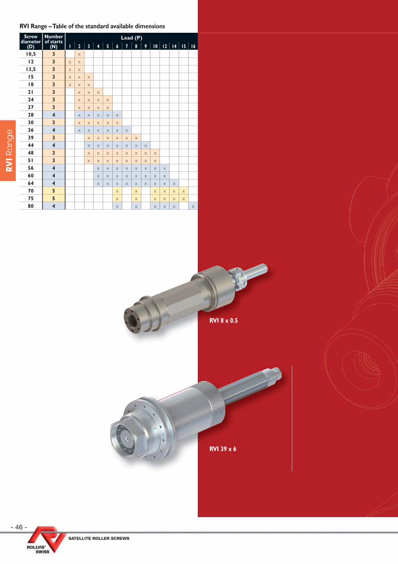
- 46 -
RV
I R
an
ge
Screw diameter
(D)
Number of starts
(N)
Lead (P)
1 2 3 4 5 6 7 8 9 10 12 14 15 1610,5 3 x12 3 x x
13,5 3 x x15 3 x x x18 3 x x x21 3 x x x24 3 x x x x27 3 x x x x28 4 x x x x x30 3 x x x x x36 4 x x x x x x39 3 x x x x x x44 4 x x x x x x x48 3 x x x x x x x x51 3 x x x x x x x x56 4 x x x x x x x x60 4 x x x x x x x x64 4 x x x x x x x x x70 5 x x x x x x75 5 x x x x x x80 4 x x x x x x
RVI Range – Table of the standard available dimensions
RVI 8 x 0.5
RVI 39 x 6

- 47 -
RV
I R
an
ge
RVI Range - Inverted satellite roller screws
Dimensions pages
RVI 10,5 / 12 / 13,5 / 15 / 18 / 21 / 24 / 27 / 28 58
RVI 30 / 36 / 39 / 44 / 48 49
RVI 51 / 56 / 60 50
RVI 64 / 70 / 75 / 80 51
RV
I R
an
ge
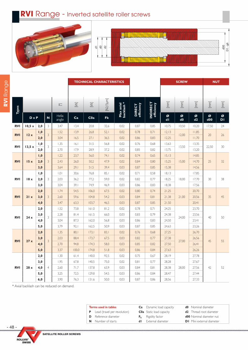
- 48 -
RV
I R
an
ge TECHNICAL CHARACTERISTICS SCREW NUT
Type
s [°] [kN
]
[kN
]
[N2/
3µm
]
Max
axi
al
back
lash
*
DIR
EC
T
effi
cien
cy
IND
IRE
CT
ef
fi ci
ency
[mm
]
[mm
]
[mm
]
[mm
]
[mm
]
D x P N Helix angle Ca C0a Fk Ø
d1Ød0
Ød2
Ød00
ØD1
RVI 10,5 x 2,0 3 3,47 13,4 20,8 32,6 0,02 0,87 0,85 10,75 10,50 10,20 17,50 24
RVI 12 x1,0
31,52 13,9 26,8 52,1 0,02 0,78 0,71 12,13
12,0011,85
20 262,0 3,04 16,5 27,1 36,5 0,02 0,86 0,83 12,25 11,70
RVI 13,5 x1,0
31,35 16,1 31,5 56,8 0,02 0,76 0,68 13,63
13,5013,35
22,50 302,0 2,70 17,9 28,9 37,2 0,02 0,85 0,82 13,75 13,20
RVI 15 x
1,0
3
1,22 23,7 56,0 74,1 0,02 0,74 0,65 15,13
15,00
14,85
25 322,0 2,43 26,0 50,2 47,9 0,02 0,84 0,80 15,25 14,70
3,0 3,64 29,1 51,5 39,4 0,03 0,87 0,85 15,38 14,56
RVI 18 x
1,0
3
1,01 30,6 76,8 85,1 0,02 0,71 0,58 18,13
18,00
17,85
30 382,0 2,03 36,2 77,2 59,0 0,02 0,82 0,77 18,25 17,70
3,0 3,04 39,1 74,9 46,9 0,03 0,86 0,83 18,38 17,56
RVI 21 x
2,0
3
1,74 54,5 106,0 67,5 0,02 0,80 0,74 21,25
21,00
20,70
35 453,0 2,60 59,6 104,8 54,2 0,03 0,84 0,81 21,38 20,56
4,0 3,47 63,3 103,7 46,5 0,03 0,87 0,85 21,50 20,41
RVI 24 x
2,0
3
1,52 73,8 161,0 81,2 0,02 0,78 0,71 24,25
24,00
23,70
40 503,0 2,28 81,4 161,5 66,0 0,03 0,83 0,79 24,38 23,56
4,0 3,04 87,3 162,0 56,8 0,03 0,86 0,83 24,50 23,41
5,0 3,79 92,1 162,5 50,9 0,03 0,87 0,85 24,63 23,26
RVI 27 x
2,0
3
1,35 80,1 173,1 83,1 0,02 0,76 0,68 27,25
27,00
26,70
45 553,0 2,03 88,4 173,7 67,5 0,03 0,82 0,77 27,38 26,56
4,0 2,70 94,8 174,3 58,0 0,03 0,85 0,82 27,50 26,41
5,0 3,37 100,0 174,8 51,8 0,03 0,86 0,84 27,63 26,26
RVI 28 x
2,0
4
1,30 61,4 140,0 92,5 0,02 0,75 0,67 28,19
28,00
27,78
42 52
3,0 1,95 67,8 140,5 75,0 0,02 0,81 0,77 28,28 27,67
4,0 2,60 71,7 137,8 63,9 0,03 0,84 0,81 28,38 27,56
5,0 3,25 72,5 129,8 54,5 0,03 0,86 0,84 28,47 27,44
6,0 3,90 76,3 131,6 50,0 0,03 0,87 0,86 28,56 27,33
* Axial backlash can be reduced on demand.
RVI Range - Inverted satellite roller screws
Terms used in tables Ca Dynamic load capacity d0 Nominal diameterP Lead (travel per revolution) C0a Static load capacity d2 Thread root diameterD Reference diameter Fk Rigidity factor d00 Nominal diameter nutN Number of starts d1 External diameter D1 Mini external diameter
d2d0d1 d00
D1
- g6
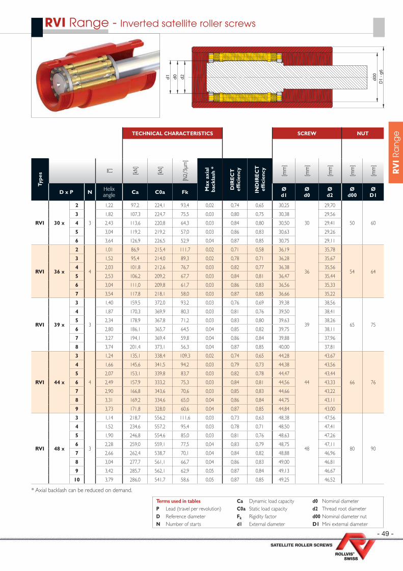
- 49 -
RV
I R
an
geTECHNICAL CHARACTERISTICS SCREW NUT
Type
s [°] [kN
]
[kN
]
[N2/
3µm
]
Max
axi
al
back
lash
*
DIR
EC
T
effi
cien
cy
IND
IRE
CT
ef
fi ci
ency
[mm
]
[mm
]
[mm
]
[mm
]
[mm
]
D x P N Helix angle Ca C0a Fk Ø
d1Ød0
Ød2
Ød00
ØD1
RVI 30 x
2
3
1,22 97,2 224,1 93,4 0,02 0,74 0,65 30,25
30
29,70
50 60
3 1,82 107,3 224,7 75,5 0,03 0,80 0,75 30,38 29,56
4 2,43 113,6 220,8 64,3 0,03 0,84 0,80 30,50 29,41
5 3,04 119,2 219,2 57,0 0,03 0,86 0,83 30,63 29,26
6 3,64 126,9 226,5 52,9 0,04 0,87 0,85 30,75 29,11
RVI 36 x
2
4
1,01 86,9 215,4 111,7 0,02 0,71 0,58 36,19
36
35,78
54 64
3 1,52 95,4 214,0 89,3 0,02 0,78 0,71 36,28 35,67
4 2,03 101,8 212,6 76,7 0,03 0,82 0,77 36,38 35,56
5 2,53 106,2 209,2 67,7 0,03 0,84 0,81 36,47 35,44
6 3,04 111,0 209,8 61,7 0,03 0,86 0,83 36,56 35,33
7 3,54 117,8 218,1 58,0 0,03 0,87 0,85 36,66 35,22
RVI 39 x
3
3
1,40 159,5 372,0 93,2 0,03 0,76 0,69 39,38
39
38,56
65 75
4 1,87 170,3 369,9 80,3 0,03 0,81 0,76 39,50 38,41
5 2,34 178,9 367,8 71,2 0,03 0,83 0,80 39,63 38,26
6 2,80 186,1 365,7 64,5 0,04 0,85 0,82 39,75 38,11
7 3,27 194,1 369,4 59,8 0,04 0,86 0,84 39,88 37,96
8 3,74 201,4 373,1 56,3 0,04 0,87 0,85 40,00 37,81
RVI 44 x
3
4
1,24 135,1 338,4 109,3 0,02 0,74 0,65 44,28
44
43,67
66 76
4 1,66 145,6 341,5 94,2 0,03 0,79 0,73 44,38 43,56
5 2,07 153,1 339,8 83,7 0,03 0,82 0,78 44,47 43,44
6 2,49 157,9 333,2 75,3 0,03 0,84 0,81 44,56 43,33
7 2,90 166,8 343,6 70,6 0,03 0,85 0,83 44,66 43,22
8 3,31 169,2 334,6 65,0 0,04 0,86 0,84 44,75 43,11
9 3,73 171,8 328,0 60,6 0,04 0,87 0,85 44,84 43,00
RVI 48 x
3
3
1,14 218,7 556,2 111,6 0,03 0,73 0,63 48,38
48
47,56
80 90
4 1,52 234,6 557,2 95,4 0,03 0,78 0,71 48,50 47,41
5 1,90 246,8 554,6 85,0 0,03 0,81 0,76 48,63 47,26
6 2,28 259,0 559,1 77,5 0,04 0,83 0,79 48,75 47,11
7 2,66 262,4 538,7 70,1 0,04 0,84 0,82 48,88 46,96
8 3,04 277,7 561,1 66,7 0,04 0,86 0,83 49,00 46,81
9 3,42 285,7 562,1 62,9 0,05 0,87 0,84 49,13 46,67
10 3,79 286,0 541,7 58,6 0,05 0,87 0,85 49,25 46,52
* Axial backlash can be reduced on demand.
RVI Range - Inverted satellite roller screws
d2d0d1 d00
D1
- g6
Terms used in tables Ca Dynamic load capacity d0 Nominal diameterP Lead (travel per revolution) C0a Static load capacity d2 Thread root diameterD Reference diameter Fk Rigidity factor d00 Nominal diameter nutN Number of starts d1 External diameter D1 Mini external diameter

- 50 -
RV
I R
an
ge TECHNICAL CHARACTERISTICS SCREW NUT
Type
s [°] [kN
]
[kN
]
[N2/
3µm
]
Max
axi
al
back
lash
*
DIR
EC
T
effi
cien
cy
IND
IRE
CT
ef
fi ci
ency
[mm
]
[mm
]
[mm
]
[mm
]
[mm
]
D x P N Helix angle Ca C0a Fk Ø
d1Ød0
Ød2
Ød00
ØD1
RVI 51 x
3
3
1,07 263,1 725,9 126,3 0,03 0,72 0,60 51,38
51
50,56
85 99
4 1,43 279,5 715,2 106,6 0,03 0,77 0,70 51,50 50,41
5 1,79 298,1 727,9 96,2 0,03 0,80 0,75 51,63 50,26
6 2,14 308,5 717,3 86,9 0,04 0,82 0,78 51,75 50,11
7 2,50 320,2 718,3 80,0 0,04 0,84 0,81 51,88 49,96
8 2,86 326,2 703,9 74,0 0,04 0,85 0,83 52,00 49,81
9 3,22 340,3 720,4 70,3 0,05 0,86 0,84 52,13 49,67
10 3,57 346,6 713,7 66,5 0,05 0,87 0,85 52,25 49,52
RVI 56 x
4
4
1,30 219,6 584,9 119,0 0,03 0,75 0,67 56,38
56
55,56
84 98
5 1,63 231,9 585,8 105,9 0,03 0,79 0,73 56,47 55,44
6 1,95 240,8 580,4 96,0 0,03 0,81 0,77 56,56 55,33
7 2,28 250,8 584,4 88,8 0,03 0,83 0,79 56,66 55,22
8 2,60 256,5 575,9 82,2 0,04 0,84 0,81 56,75 55,11
9 2,93 260,4 564,4 76,6 0,04 0,85 0,83 56,84 55,00
10 3,25 274,4 590,0 74,1 0,04 0,86 0,84 56,94 54,89
12 3,90 279,0 566,9 66,2 0,05 0,87 0,86 57,13 54,67
RVI 60 x
4
4
1,22 248,6 689,4 128,2 0,03 0,74 0,65 60,38
60
59,56
90 108
5 1,52 259,3 676,9 112,7 0,03 0,78 0,71 60,47 59,44
6 1,82 272,7 684,5 103,1 0,03 0,80 0,75 60,56 59,33
7 2,13 281,4 678,7 94,8 0,03 0,82 0,78 60,66 59,22
8 2,43 290,7 679,7 88,3 0,04 0,84 0,80 60,75 59,11
9 2,73 298,2 677,2 83,0 0,04 0,85 0,82 60,84 59,00
10 3,04 306,9 681,5 78,9 0,04 0,86 0,83 60,94 58,89
12 3,64 316,7 669,9 71,2 0,05 0,87 0,85 61,13 58,67
* Axial backlash can be reduced on demand.
RVI Range - Inverted satellite roller screws
d2d0d1 d00
D1
- g6
Terms used in tables Ca Dynamic load capacity d0 Nominal diameterP Lead (travel per revolution) C0a Static load capacity d2 Thread root diameterD Reference diameter Fk Rigidity factor d00 Nominal diameter nutN Number of starts d1 External diameter D1 Mini external diameter
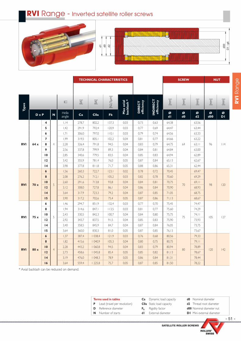
- 51 -
RV
I R
an
geTECHNICAL CHARACTERISTICS SCREW NUT
Type
s [°] [kN
]
[kN
]
[N2/
3µm
]
Max
axi
al
back
lash
*
DIR
EC
T
effi
cien
cy
IND
IRE
CT
ef
fi ci
ency
[mm
]
[mm
]
[mm
]
[mm
]
[mm
]
D x P N Helix angle Ca C0a Fk Ø
d1Ød0
Ød2
Ød00
ØD1
RVI 64 x
4
4
1,14 278,7 802,2 137,3 0,03 0,73 0,63 64,38
64
63,56
96 114
5 1,42 291,9 792,4 120,9 0,03 0,77 0,69 64,47 63,44
6 1,71 306,0 797,0 110,1 0,03 0,79 0,74 64,56 63,33
7 1,99 319,5 805,1 102,2 0,04 0,81 0,77 64,66 63,22
8 2,28 326,4 791,8 94,5 0,04 0,83 0,79 64,75 63,11
9 2,56 337,8 799,9 89,3 0,04 0,84 0,81 64,84 63,00
10 2,85 340,6 779,5 83,5 0,04 0,85 0,83 64,94 62,89
12 3,42 355,9 781,4 76,0 0,05 0,87 0,84 65,13 62,67
14 3,98 377,8 811,8 71,7 0,05 0,88 0,86 65,31 62,44
RVI 70 x
6
5
1,56 260,3 722,7 123,1 0,02 0,78 0,72 70,45
70
69,47
98 120
8 2,08 276,2 712,1 105,2 0,03 0,82 0,78 70,60 69,29
10 2,60 291,6 713,8 93,8 0,04 0,84 0,81 70,75 69,11
12 3,12 308,0 727,8 86,1 0,04 0,86 0,84 70,90 68,93
14 3,64 317,9 723,3 79,2 0,04 0,87 0,85 71,05 68,75
15 3,90 317,2 702,6 75,4 0,05 0,87 0,86 71,13 68,67
RVI 75 x
6
5
1,46 294,7 851,9 132,4 0,03 0,77 0,70 75,45
75
74,47
105 127
8 1,94 314,6 847,1 113,5 0,03 0,81 0,77 75,60 74,29
10 2,43 330,5 842,3 100,7 0,04 0,84 0,80 75,75 74,11
12 2,92 343,7 837,5 91,5 0,04 0,85 0,83 75,90 73,93
14 3,40 358,5 845,9 84,7 0,04 0,87 0,84 76,05 73,75
15 3,64 360,0 830,3 81,0 0,05 0,87 0,85 76,13 73,67
RVI 80 x
6
4
1,37 387,4 1 038,4 121,9 0,03 0,76 0,68 80,56
80
79,33
120 142
8 1,82 415,6 1 040,9 105,3 0,04 0,80 0,75 80,75 79,11
10 2,28 443,2 1 060,8 94,5 0,04 0,83 0,79 80,94 78,89
12 2,73 458,6 1 045,8 85,4 0,05 0,85 0,82 81,13 78,67
14 3,19 476,0 1 048,3 78,9 0,05 0,86 0,84 81,31 78,44
16 3,64 559,4 1 225,8 75,7 0,05 0,87 0,85 81,50 78,22
* Axial backlash can be reduced on demand.
RVI Range - Inverted satellite roller screws
d2d0d1 d00
D1
- g6
Terms used in tables Ca Dynamic load capacity d0 Nominal diameterP Lead (travel per revolution) C0a Static load capacity d2 Thread root diameterD Reference diameter Fk Rigidity factor d00 Nominal diameter nutN Number of starts d1 External diameter D1 Mini external diameter
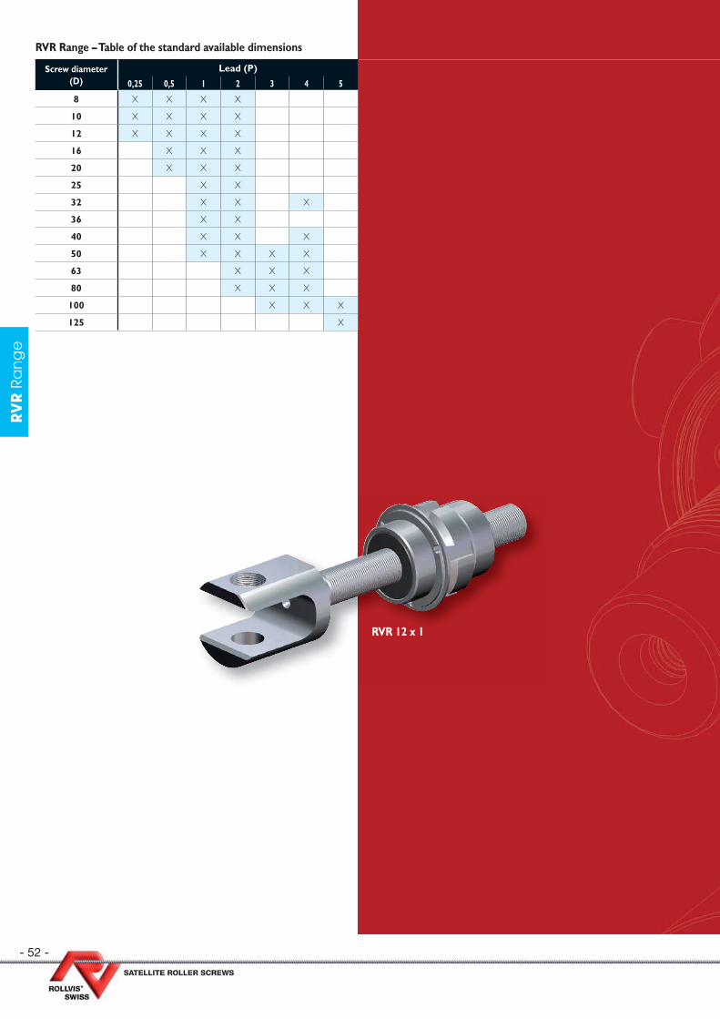
- 52 -
RV
R R
an
ge
Screw diameter (D)
Lead (P)
0,25 0,5 1 2 3 4 5
8 X X X X
10 X X X X
12 X X X X
16 X X X
20 X X X
25 X X
32 X X X
36 X X
40 X X X
50 X X X X
63 X X X
80 X X X
100 X X X
125 X
RVR Range – Table of the standard available dimensions
RVR 12 x 1
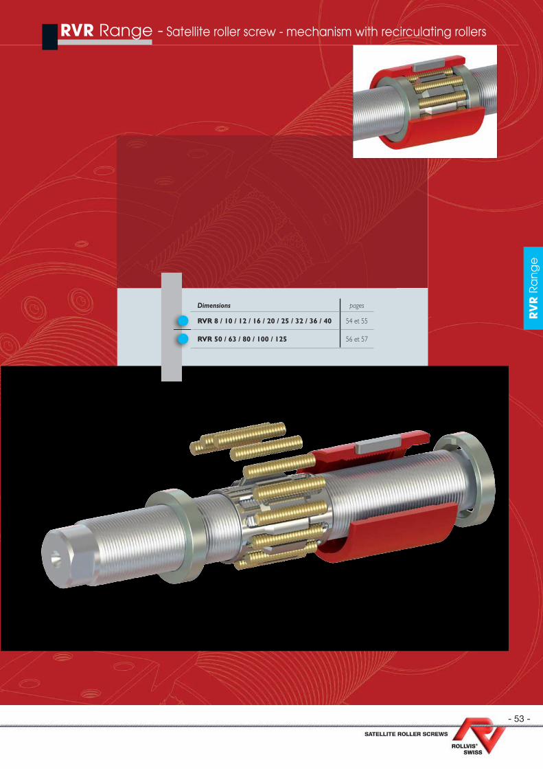
- 53 -
RV
R R
an
ge
RVR Range - Satellite roller screw - mechanism with recirculating rollers
RV
R R
an
ge
Dimensions pages
RVR 8 / 10 / 12 / 16 / 20 / 25 / 32 / 36 / 40 54 et 55
RVR 50 / 63 / 80 / 100 / 125 56 et 57

- 54 -
RV
R R
an
ge
TECHNICAL CHARACTERISTICS
SINGLE NUT SPLIT NUT
Type
s [°] [kN
]
[kN
]
[N2/
3µm
]
Max
axi
al
back
lash
*
[kN
]
[kN
]
[N2/
3µm
]
[N]
[Nm
]
DIR
EC
T
effi
cien
cy
IND
IRE
CT
ef
fi ci
ency
D x P N Helix angle Ca C0a Fk Ca C0a Fk Fv Mv
RVR 8 x
0,25
1
0,58 7,3 14,3 40,5 0,02 4,2 7,1 25,5 820 0,06 0,58 0,29
0,5 1,17 8,7 13,5 27,4 0,02 5,0 6,8 17,3 790 0,06 0,73 0,63
1 2,39 11,8 14,3 18,9 0,03 6,8 7,2 11,9 730 0,06 0,83 0,80
2 2 4,77 11,8 14,3 18,9 0,03 6,8 7,2 11,9 550 0,06 0,88 0,87
RVR 10 x
0,25
1
0,46 8,8 17,7 45,9 0,02 5,0 8,9 28,9 870 0,08 0,53 0,11
0,5 0,93 10,4 16,8 31,0 0,02 6,0 8,4 19,6 855 0,08 0,69 0,55
1 1,89 14,1 17,8 21,4 0,03 8,1 8,9 13,5 810 0,08 0,81 0,76
2 2 3,78 14,1 17,8 21,4 0,03 8,1 8,9 13,5 665 0,08 0,87 0,85
RVR 12 x
0,25
1
0,38 10,1 21,2 51,0 0,02 5,8 10,6 32,1 910 0,10 0,51 0,02
0,5 0,77 11,9 20,1 34,5 0,02 6,8 10,0 21,7 895 0,10 0,65 0,46
1 1,57 16,1 21,3 23,8 0,03 9,3 10,6 15,0 860 0,10 0,78 0,72
2 2 3,13 16,1 21,3 23,8 0,03 9,3 10,6 15,0 740 0,10 0,86 0,84
RVR 16 x
0,51
0,58 14,3 26,7 40,8 0,02 8,2 13,3 25,7 1 020 0,15 0,58 0,29
1 1,17 19,4 28,2 28,2 0,03 11,1 14,1 17,8 990 0,15 0,73 0,63
2 2 2,33 19,4 28,2 28,2 0,03 11,1 14,1 17,8 895 0,15 0,83 0,80
RVR 20 x
0,51
0,46 19,5 45,5 53,6 0,02 11,2 22,7 33,8 1 090 0,20 0,53 0,11
1 0,93 27,1 49,7 37,5 0,03 15,6 24,8 23,7 1 070 0,20 0,69 0,55
2 2 1,86 27,1 49,7 37,5 0,03 15,6 24,8 23,7 995 0,20 0,80 0,76
RVR 25 x1 1 0,74 39,7 85,2 48,3 0,03 22,8 42,6 30,4 1 295 0,30 0,64 0,44
2 2 1,48 39,7 85,2 48,3 0,03 22,8 42,6 30,4 1 228 0,30 0,77 0,70
RVR 32 x
1 1 0,58 60,8 148,9 61,0 0,03 34,9 74,4 38,4 1 698 0,50 0,58 0,29
22
1,15 60,8 148,9 61,0 0,03 34,9 74,4 38,4 1 635 0,50 0,73 0,63
4 2,33 73,5 144,7 42,6 0,03 42,2 72,4 26,8 1 493 0,50 0,83 0,80
RVR 36 x1
10,51 73,8 180,5 64,1 0,03 42,4 90,2 40,4 1 815 0,60 0,56 0,20
2 1,03 86,5 171,5 44,2 0,03 49,7 85,7 27,9 1 775 0,60 0,71 0,59
RVR 40 x
1 1 0,46 79,8 206,9 69,5 0,03 45,8 103,5 43,8 1 908 0,70 0,53 0,11
22
0,92 79,8 206,9 69,5 0,03 45,8 103,5 43,8 1 857 0,70 0,69 0,54
4 1,86 97,3 199,0 47,7 0,03 55,9 99,5 30,0 1 740 0,70 0,80 0,76
* Axial backlash can be reduced on demand.
RVR Range - Satellite roller screw - mechanism with recirculating rollers
Terms used in tables N Number of starts Fk Rigidity factorP Lead (travel per revolution) Ca Dynamic load capacity Fv Preloading forceD Reference diameter C0a Static load capacity Mv Preload torque
d1 d2d0
D4= =
L4 h
9
= L3 =L1 h12
D3
H6
D1
g6
L2 d1 d2d0
D3
H6
D1
g6
D2
h13
L5L1 h12110 ou 111
Type160 ou 161
Type
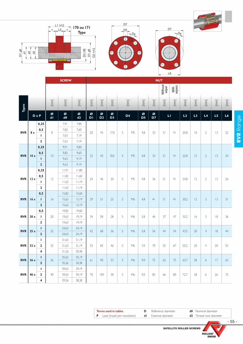
- 55 -
RV
R R
an
ge
SCREW NUT
With
out
wip
er
With
w
iper
s
Type
s [mm
]
[mm
]
[mm
]
[mm
]
[mm
]
[mm
]
[mm
]
[mm
]
[mm
]
[mm
]
[mm
]
[mm
]
[mm
]
[mm
]
[mm
]
[mm
]
D x P Ød1
Ød0
Ød2
ØD1
Ø D2
Ø D3 D4 Ø
D5Ø D7 L1 L2 L3 L4 L5 L6
RVR 8 x
0,25
8
7,91 7,80
20 43 17,0 5 M5 4,8 33 31 41 20,8 10 2 13 220,5 7,82 7,60
1 7,63 7,19
2 7,63 7,19
RVR 10 x
0,25
10
9,91 9,80
22 43 18,5 5 M5 4,8 33 31 41 22,8 12 2 13 240,5 9,82 9,60
1 9,63 9,19
2 9,63 9,19
RVR 12 x
0,25
12
11,91 11,80
24 46 20 5 M5 4,8 36 31 41 24,8 12 2 13 260,5 11,82 11,60
1 11,63 11,19
2 11,63 11,19
RVR 16 x
0,5
16
15,82 15,60
29 51 25 5 M6 4,8 41 31 41 30,2 12 3 13 311 15,63 15,19
2 15,63 15,19
RVR 20 x
0,5
20
19,82 19,60
34 58 28 5 M6 5,8 46 37 47 35,2 16 3 18 361 19,63 19,19
2 19,63 19,19
RVR 25 x1
2524,63 24,19
42 68 36 5 M6 5,8 56 44 54 43,5 20 4 18 442 24,63 24,19
RVR 32 x
1
32
31,63 31,19
53 83 46 5 M6 7,0 70 55 67 55,2 20 4 20 552 31,63 31,19
4 31,26 30,38
RVR 36 x1
3635,63 35,19
61 90 53 5 M6 9,0 75 62 75 63,7 28 6 17 632 35,26 34,38
RVR 40 x
1
40
39,63 39,19
70 104 58 5 M6 9,0 85 66 80 72,7 28 6 26 722 39,63 39,19
4 39,26 38,38
Terms used in tables D Reference diameter d0 Nominal diameterP Lead (travel per revolution) d1 External diameter d2 Thread root diameter
d1 d2d0
D3
H6
D1
g6
= L5 =L1 h12
D1
g6
D2
h13
D4
D7
D5 D7D4
L6
170 ou 171Type
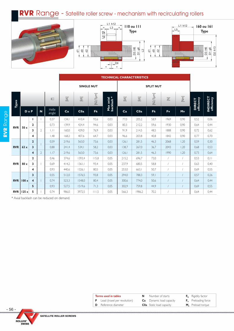
- 56 -
RV
R R
an
ge
TECHNICAL CHARACTERISTICS
SINGLE NUT SPLIT NUT
Type
s [°] [kN
]
[kN
]
[N2/
3µm
]
Max
axi
al
back
lash
*
[kN
]
[kN
]
[N2/
3µm
]
[N]
[Nm
]
DIR
EC
T
effi
cien
cy
IND
IRE
CT
ef
fi ci
ency
D x P N Helix angle Ca C0a Fk Ca C0a Fk Fv Mv
RVR 50 x
1 1 0,37 134,1 410,4 93,6 0,03 77,0 205,2 58,9 1969 0,90 0,52 0,06
2
2
0,73 139,9 424,4 94,6 0,03 80,3 212,2 59,6 1930 0,90 0,64 0,44
3 1,11 160,0 429,0 76,9 0,03 91,9 214,5 48,5 1888 0,90 0,72 0,62
4 1,48 168,2 407,6 64,7 0,03 96,6 203,8 40,8 1842 0,90 0,77 0,70
RVR 63 x
21
0,59 219,6 563,0 73,6 0,03 126,1 281,5 46,3 2068 1,20 0,59 0,30
3 0,88 241,4 534,1 58,2 0,03 138,7 267,0 36,7 2043 1,20 0,68 0,53
4 2 1,17 219,6 563,0 73,6 0,03 126,1 281,5 46,3 1990 1,20 0,73 0,64
RVR 80 x
2
1
0,46 374,6 1393,4 115,8 0,05 215,2 696,7 73,0 / / 0,53 0,11
3 0,69 414,2 1361,1 93,4 0,05 237,9 680,5 58,8 / / 0,63 0,40
4 0,93 440,6 1326,1 80,5 0,05 253,0 663,1 50,7 / / 0,69 0,55
RVR 100 x
3
1
0,55 512,0 1576,5 93,8 0,05 294,0 788,3 59,1 / / 0,57 0,26
4 0,74 523,3 1548,0 80,4 0,05 300,6 774,0 50,6 / / 0,64 0,44
5 0,93 527,5 1519,6 71,3 0,05 302,9 759,8 44,9 / / 0,69 0,55
RVR 125 x 5 1 0,74 986,0 3972,5 111,5 0,05 566,3 1986,2 70,2 / / 0,64 0,44
* Axial backlash can be reduced on demand.
RVR Range - Satellite roller screw - mechanism with recirculating rollers
d1 d2d0
D4= =
L4 h
9
= L3 =L1 h12
D3
H6
D1
g6
L2 d1 d2d0
D3
H6
D1
g6
D2
h13
L5L1 h12110 ou 111
Type160 ou 161
Type
Terms used in tables N Number of starts Fk Rigidity factorP Lead (travel per revolution) Ca Dynamic load capacity Fv Preloading forceD Reference diameter C0a Static load capacity Mv Preload torque

- 57 -
RV
R R
an
ge
SCREW NUT
With
out
wip
er
With
w
iper
s
Type
s [mm
]
[mm
]
[mm
]
[mm
]
[mm
]
[mm
]
[mm
]
[mm
]
[mm
]
[mm
]
[mm
]
[mm
]
[mm
]
[mm
]
[mm
]
[mm
]
D x P Ød1
Ød0
Ød2
ØD1
Ø D2
Ø D3 D4 Ø
D5Ø D7 L1 L2 L3 L4 L5 L6
RVR 50 x
1
50
49,63 49,19
82 124 74 8 M6 11,0 102 85 101 84,7 32 6 28 842 49,63 49,19
3 49,45 48,79
4 49,26 48,38
RVR 63 x
2
63
62,26 61,38
102 148 94 8 M8 x 1 13,5 127 110 124 104,7 40 6 32 1043 61,89 60,57
4 62,26 61,38
RVR 80 x
2
80
79,26 78,38
140 198 115 10 M8 x 1 17,5 170 175 189 141,7 50 10 35 1403 78,89 77,57
4 78,52 76,76
RVR 100 x
3
100
98,89 97,57
174 238 146 10 M8 x 1 17,5 210 180 196 173,7 56 12 40 1724 98,52 96,76
5 98,15 95,95
RVR 125 x 5 125 123,15 120,95 220 310 188 15 M10 x 1 20,0 270 262 282 223 100 12 55 225
Terms used in tables D Reference diameter d0 Nominal diameterP Lead (travel per revolution) d1 External diameter d2 Thread root diameter
d1 d2d0
D3
H6
D1
g6
= L5 =L1 h12
D1
g6
D2
h13
D4
D7
D5 D7D4
L6
170 ou 171Type
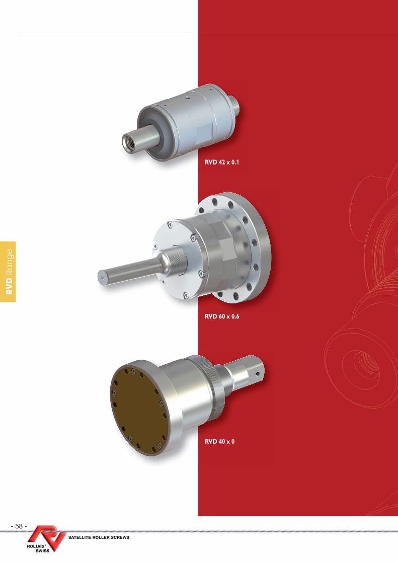
- 58 -
RV
D R
an
ge
RVD 42 x 0.1
RVD 60 x 0.6
RVD 40 x 0

- 59 -
RV
D R
an
ge
RVD Range - Differential roller screws
Dimensions pages
RVD 12 / 15 / 18 60
RVD 21/ 24 / 27 61
RVD 30 / 33 62
RVD 36 / 39 63
RV
D R
an
ge
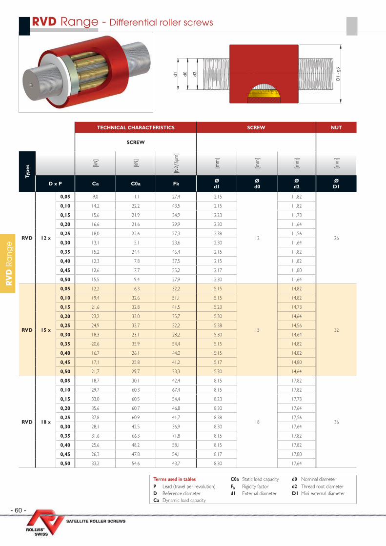
- 60 -
RV
D R
an
ge
RVD Range - Differential roller screws
TECHNICAL CHARACTERISTICS SCREW NUT
SCREW
Type
s [kN
]
[kN
]
[N2/
3µm
]
[mm
]
[mm
]
[mm
]
[mm
]
D x P Ca C0a Fk Ød1
Ød0
Ød2
ØD1
RVD 12 x
0,05 9,0 11,1 27,4 12,15
12
11,82
26
0,10 14,2 22,2 43,5 12,15 11,82
0,15 15,6 21,9 34,9 12,23 11,73
0,20 16,6 21,6 29,9 12,30 11,64
0,25 18,0 22,6 27,3 12,38 11,56
0,30 13,1 15,1 23,6 12,30 11,64
0,35 15,2 24,4 46,4 12,15 11,82
0,40 12,3 17,8 37,5 12,15 11,82
0,45 12,6 17,7 35,2 12,17 11,80
0,50 15,5 19,4 27,9 12,30 11,64
RVD 15 x
0,05 12,2 16,3 32,2 15,15
15
14,82
32
0,10 19,4 32,6 51,1 15,15 14,82
0,15 21,6 32,8 41,5 15,23 14,73
0,20 23,2 33,0 35,7 15,30 14,64
0,25 24,9 33,7 32,2 15,38 14,56
0,30 18,3 23,1 28,2 15,30 14,64
0,35 20,6 35,9 54,4 15,15 14,82
0,40 16,7 26,1 44,0 15,15 14,82
0,45 17,1 25,8 41,2 15,17 14,80
0,50 21,7 29,7 33,3 15,30 14,64
RVD 18 x
0,05 18,7 30,1 42,4 18,15
18
17,82
36
0,10 29,7 60,3 67,4 18,15 17,82
0,15 33,0 60,5 54,4 18,23 17,73
0,20 35,6 60,7 46,8 18,30 17,64
0,25 37,8 60,9 41,7 18,38 17,56
0,30 28,1 42,5 36,9 18,30 17,64
0,35 31,6 66,3 71,8 18,15 17,82
0,40 25,6 48,2 58,1 18,15 17,82
0,45 26,3 47,8 54,1 18,17 17,80
0,50 33,2 54,6 43,7 18,30 17,64
Terms used in tables C0a Static load capacity d0 Nominal diameterP Lead (travel per revolution) Fk Rigidity factor d2 Thread root diameterD Reference diameter d1 External diameter D1 Mini external diameterCa Dynamic load capacity
d0d1 d2
D1
- g6
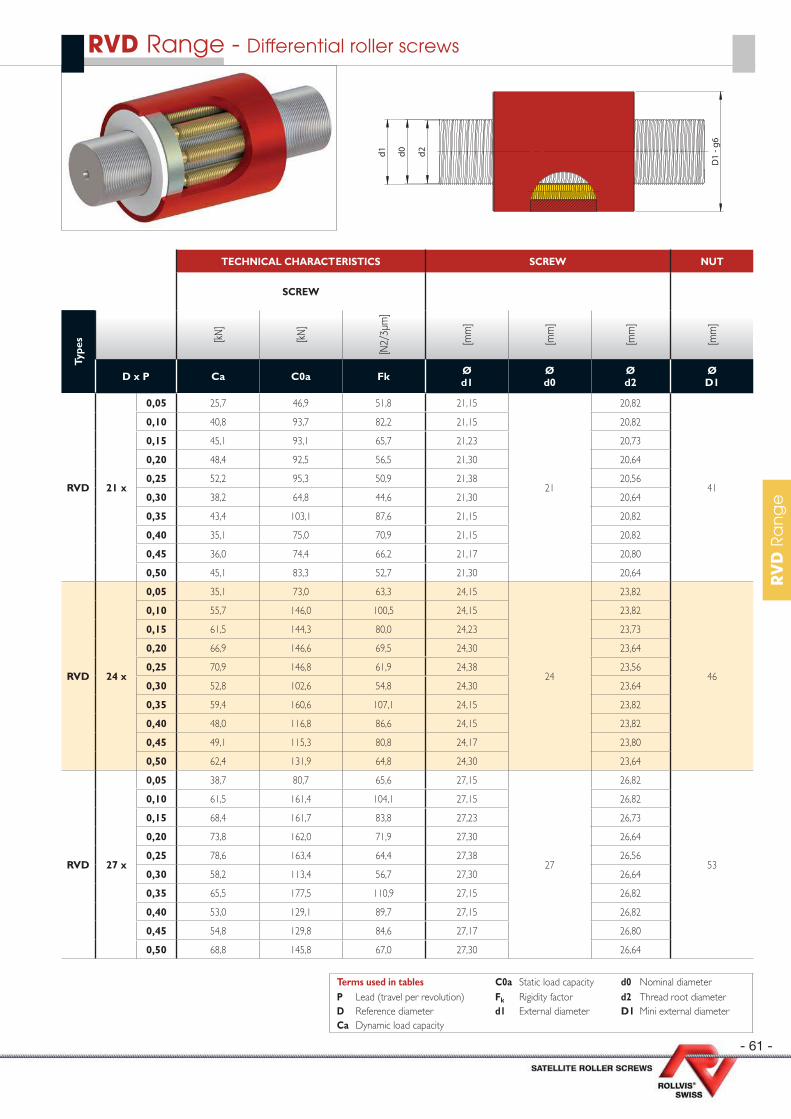
- 61 -
RV
D R
an
ge
RVD Range - Differential roller screws
TECHNICAL CHARACTERISTICS SCREW NUT
SCREW
Type
s [kN
]
[kN
]
[N2/
3µm
]
[mm
]
[mm
]
[mm
]
[mm
]
D x P Ca C0a Fk Ød1
Ød0
Ød2
ØD1
RVD 21 x
0,05 25,7 46,9 51,8 21,15
21
20,82
41
0,10 40,8 93,7 82,2 21,15 20,82
0,15 45,1 93,1 65,7 21,23 20,73
0,20 48,4 92,5 56,5 21,30 20,64
0,25 52,2 95,3 50,9 21,38 20,56
0,30 38,2 64,8 44,6 21,30 20,64
0,35 43,4 103,1 87,6 21,15 20,82
0,40 35,1 75,0 70,9 21,15 20,82
0,45 36,0 74,4 66,2 21,17 20,80
0,50 45,1 83,3 52,7 21,30 20,64
RVD 24 x
0,05 35,1 73,0 63,3 24,15
24
23,82
46
0,10 55,7 146,0 100,5 24,15 23,82
0,15 61,5 144,3 80,0 24,23 23,73
0,20 66,9 146,6 69,5 24,30 23,64
0,25 70,9 146,8 61,9 24,38 23,56
0,30 52,8 102,6 54,8 24,30 23,64
0,35 59,4 160,6 107,1 24,15 23,82
0,40 48,0 116,8 86,6 24,15 23,82
0,45 49,1 115,3 80,8 24,17 23,80
0,50 62,4 131,9 64,8 24,30 23,64
RVD 27 x
0,05 38,7 80,7 65,6 27,15
27
26,82
53
0,10 61,5 161,4 104,1 27,15 26,82
0,15 68,4 161,7 83,8 27,23 26,73
0,20 73,8 162,0 71,9 27,30 26,64
0,25 78,6 163,4 64,4 27,38 26,56
0,30 58,2 113,4 56,7 27,30 26,64
0,35 65,5 177,5 110,9 27,15 26,82
0,40 53,0 129,1 89,7 27,15 26,82
0,45 54,8 129,8 84,6 27,17 26,80
0,50 68,8 145,8 67,0 27,30 26,64
Terms used in tables C0a Static load capacity d0 Nominal diameterP Lead (travel per revolution) Fk Rigidity factor d2 Thread root diameterD Reference diameter d1 External diameter D1 Mini external diameterCa Dynamic load capacity
d0d1 d2
D1
- g6
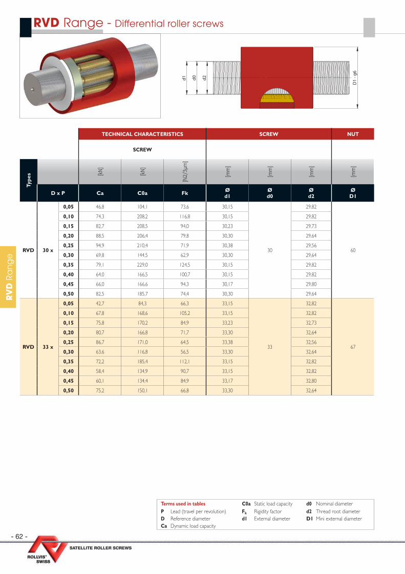
- 62 -
RV
D R
an
ge
RVD Range - Differential roller screws
TECHNICAL CHARACTERISTICS SCREW NUT
SCREW
Type
s [kN
]
[kN
]
[N2/
3µm
]
[mm
]
[mm
]
[mm
]
[mm
]
D x P Ca C0a Fk Ød1
Ød0
Ød2
ØD1
RVD 30 x
0,05 46,8 104,1 73,6 30,15
30
29,82
60
0,10 74,3 208,2 116,8 30,15 29,82
0,15 82,7 208,5 94,0 30,23 29,73
0,20 88,5 206,4 79,8 30,30 29,64
0,25 94,9 210,4 71,9 30,38 29,56
0,30 69,8 144,5 62,9 30,30 29,64
0,35 79,1 229,0 124,5 30,15 29,82
0,40 64,0 166,5 100,7 30,15 29,82
0,45 66,0 166,6 94,3 30,17 29,80
0,50 82,5 185,7 74,4 30,30 29,64
RVD 33 x
0,05 42,7 84,3 66,3 33,15
33
32,82
67
0,10 67,8 168,6 105,2 33,15 32,82
0,15 75,8 170,2 84,9 33,23 32,73
0,20 80,7 166,8 71,7 33,30 32,64
0,25 86,7 171,0 64,5 33,38 32,56
0,30 63,6 116,8 56,5 33,30 32,64
0,35 72,2 185,4 112,1 33,15 32,82
0,40 58,4 134,9 90,7 33,15 32,82
0,45 60,1 134,4 84,9 33,17 32,80
0,50 75,2 150,1 66,8 33,30 32,64
d0d1 d2
D1
- g6
Terms used in tables C0a Static load capacity d0 Nominal diameterP Lead (travel per revolution) Fk Rigidity factor d2 Thread root diameterD Reference diameter d1 External diameter D1 Mini external diameterCa Dynamic load capacity
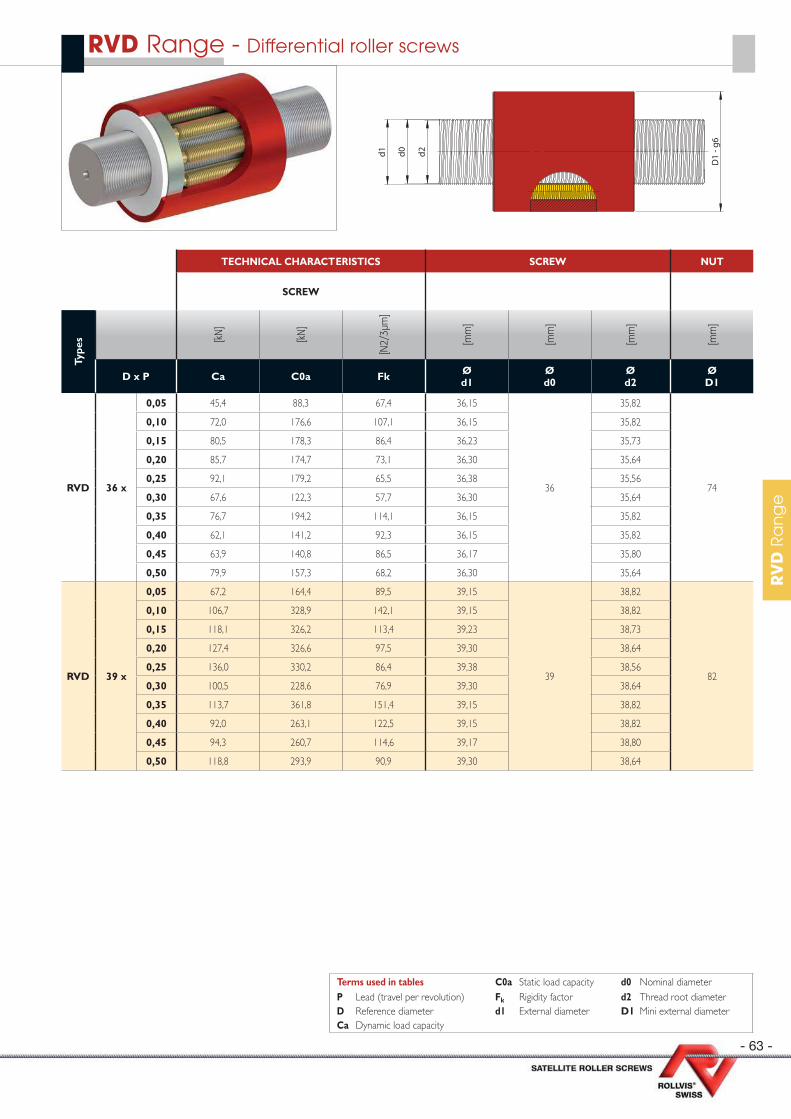
- 63 -
RV
D R
an
ge
RVD Range - Differential roller screws
TECHNICAL CHARACTERISTICS SCREW NUT
SCREW
Type
s [kN
]
[kN
]
[N2/
3µm
]
[mm
]
[mm
]
[mm
]
[mm
]
D x P Ca C0a Fk Ød1
Ød0
Ød2
ØD1
RVD 36 x
0,05 45,4 88,3 67,4 36,15
36
35,82
74
0,10 72,0 176,6 107,1 36,15 35,82
0,15 80,5 178,3 86,4 36,23 35,73
0,20 85,7 174,7 73,1 36,30 35,64
0,25 92,1 179,2 65,5 36,38 35,56
0,30 67,6 122,3 57,7 36,30 35,64
0,35 76,7 194,2 114,1 36,15 35,82
0,40 62,1 141,2 92,3 36,15 35,82
0,45 63,9 140,8 86,5 36,17 35,80
0,50 79,9 157,3 68,2 36,30 35,64
RVD 39 x
0,05 67,2 164,4 89,5 39,15
39
38,82
82
0,10 106,7 328,9 142,1 39,15 38,82
0,15 118,1 326,2 113,4 39,23 38,73
0,20 127,4 326,6 97,5 39,30 38,64
0,25 136,0 330,2 86,4 39,38 38,56
0,30 100,5 228,6 76,9 39,30 38,64
0,35 113,7 361,8 151,4 39,15 38,82
0,40 92,0 263,1 122,5 39,15 38,82
0,45 94,3 260,7 114,6 39,17 38,80
0,50 118,8 293,9 90,9 39,30 38,64
d0d1 d2
D1
- g6
Terms used in tables C0a Static load capacity d0 Nominal diameterP Lead (travel per revolution) Fk Rigidity factor d2 Thread root diameterD Reference diameter d1 External diameter D1 Mini external diameterCa Dynamic load capacity
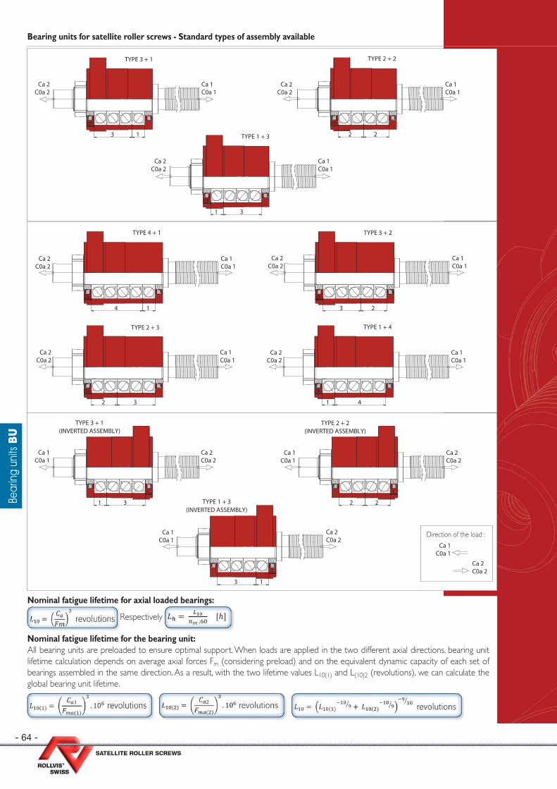
- 64 -
Bear
ing
units
BU
Bearing units for satellite roller screws - Standard types of assembly available
3 1
TYPE 3 + 1
Ca 1C0a 1
Ca 2C0a 2
2 2
TYPE 2 + 2
Ca 2C0a 2
Ca 1C0a 1
1 3
TYPE 1 + 3
Ca 1C0a 1
Ca 2C0a 2
3 2
TYPE 3 + 2
Ca 1C0a 1
Ca 2C0a 2
4 1
TYPE 4 + 1
Ca 2C0a 2
Ca 1C0a 1
2 3
TYPE 2 + 3
Ca 1C0a 1
Ca 2C0a 2
1 4
TYPE 1 + 4
Ca 1C0a 1
Ca 2C0a 2
1 3
TYPE 3 + 1(INVERTED ASSEMBLY)
Ca 1C0a 1
Ca 2C0a 2
2 2
TYPE 2 + 2(INVERTED ASSEMBLY)
Ca 2C0a 2
Ca 1C0a 1
3 1
TYPE 1 + 3(INVERTED ASSEMBLY)
Ca 1C0a 1
Ca 2C0a 2
Direction of the load :
Ca 1C0a 1
Ca 2C0a 2
Nominal fatigue lifetime for axial loaded bearings:
Respectively
Nominal fatigue lifetime for the bearing unit:All bearing units are preloaded to ensure optimal support. When loads are applied in the two different axial directions, bearing unit lifetime calculation depends on average axial forces Fm (considering preload) and on the equivalent dynamic capacity of each set of bearings assembled in the same direction. As a result, with the two lifetime values L10(1) and L(10)2 (revolutions), we can calculate the global bearing unit lifetime.

- 65 -
Bear
ing
units
BU
BU - Bearing units for roller screws
Type pages
BU 1 / 2 / 3 / 4 / 5 / 6 / 6L / 7 / 7L 66
BU 8 / 8L / 9 / 9XL 67
Shaft ends dimensions 68
Bear
ing
units
BU
Standardbearing unit
Long bearing unit
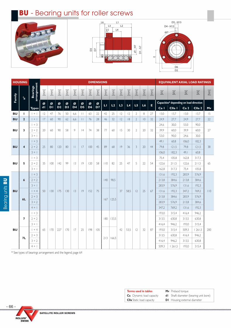
- 66 -
Bear
ing
units
BU
BU - Bearing units for roller screws
HOUSING
Bea
ring
s ar
rang
emen
t DIMENSIONS EQUIVALENT AXIAL LOAD RATINGS
Fam
ily
n°
[mm
]
[mm
]
[mm
]
[mm
]
[mm
]
[mm
]
[mm
]
[mm
]
[mm
]
[mm
]
[mm
]
[mm
]
[mm
]
[mm
]
[mm
]
[kN
]
[kN
]
[kN
]
[kN
]
[Nm
]
Ø d1
Ø D1
Ø D2
Ø D3
Ø D4
Ø D5
Ø D6
Ø D7 L1 L2 L3 L4 L5 L6 E
Capacities* depending on load direction
Types Ca 1 C0a 1 Ca 2 C0a 2 Mv
BU 1 1 + 1 12 47 76 50 6,6 11 63 22 42 25 12 12 2 8 27 13,0 13,7 13,0 13,7 15
BU 2 1 + 1 17 60 90 62 6,6 11 76 28 46 32 12 18 2 10 32 24,9 27,7 24,9 27,7 22
BU 3
1 + 3
20 60 90 58 9 14 74 38 77 60 15 30 2 20 32
24,6 30,0 53,0 90,0
272 + 2 39,9 60,0 39,9 60,0
3 + 1 53,0 90,0 24,6 30,0
BU 4
1 + 3
25 80 120 80 11 17 100 45 89 68 19 36 3 20 44
49,1 60,8 106,0 182,3
382 + 2 79,8 121,5 79,8 121,5
3 + 1 106,0 182,3 49,1 60,8
BU 5
1 + 3
35 100 142 99 13 19 120 58 110 82 25 47 5 22 54
75,4 105,8 162,8 317,3
652 + 2 122,6 211,5 122,6 211,5
3 + 1 162,8 317,3 75,4 105,8
BU
6
1 + 3
50 130 175 130 13 19 152 75
140 98,5
37 58,5 12 25 67
131,6 192,3 283,9 576,9
110
2 + 2 213,8 384,6 213,8 384,6
3 + 1 283,9 576,9 131,6 192,3
6L
1 + 4
167 125,5
131,6 192,3 347,2 769,2
2 + 3 213,8 384,6 283,9 576,9
3 + 2 283,9 576,9 213,8 384,6
4 + 1 347,2 769,2 131,6 192,3
BU
7
1 + 3
65 170 227 170 17 25 198 105
180 133,5
42 53,5 12 32 87
193,0 315,4 416,4 946,2
200
2 + 2 313,5 630,8 313,5 630,8
3 + 1 416,4 946,2 193,0 315,4
7L
1 + 4
213 166,5
193,0 315,4 509,3 1 261,5
2 + 3 313,5 630,8 416,4 946,2
3 + 2 416,4 946,2 313,5 630,8
4 + 1 509,3 1 261,5 193,0 315,4
* See types of bearings arrangement and the legend, page 64
Terms used in tables Mv Prelaod torqueCa Dynamic load capacity d1 Shaft diameter (bearing unit bore)C0a Static load capacity D1 Housing external diameter
L6
d1 -
H7
D1
- h7
D7
L1
L4L2L3
L5
D6D2
E
60°
D5 - H13D4 - H13
D3
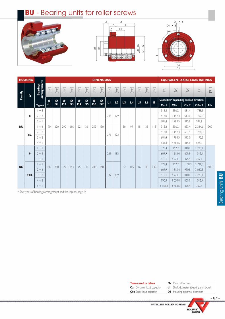
- 67 -
Bear
ing
units
BU
HOUSING
Bea
ring
s ar
rang
emen
t DIMENSIONS EQUIVALENT AXIAL LOAD RATINGS
Fam
ily
n°
[mm
]
[mm
]
[mm
]
[mm
]
[mm
]
[mm
]
[mm
]
[mm
]
[mm
]
[mm
]
[mm
]
[mm
]
[mm
]
[mm
]
[mm
]
[kN
]
[kN
]
[kN
]
[kN
]
[Nm
]
Ø d1
Ø D1
Ø D2
Ø D3
Ø D4
Ø D5
Ø D6
Ø D7 L1 L2 L3 L4 L5 L6 E
Capacities* depending on load direction
Types Ca 1 C0a 1 Ca 2 C0a 2 Mv
BU
8
1 + 3
90 220 290 216 22 32 252 130
235 179
50 99 15 38 115
315,8 596,2 681,4 1 788,5
300
2 + 2 513,0 1 192,3 513,0 1 192,3
3 + 1 681,4 1 788,5 315,8 596,2
8L
1 + 4
278 222
315,8 596,2 833,4 2 384,6
2 + 3 513,0 1 192,3 681,4 1 788,5
3 + 2 681,4 1 788,5 513,0 1 192,3
4 + 1 833,4 2 384,6 315,8 596,2
BU
9
1 + 3
100 250 327 243 25 38 285 140
253 195
52 115 16 38 130
375,4 757,7 810,1 2 273,1
400
2 + 2 609,9 1 515,4 609,9 1 515,4
3 + 1 810,1 2 273,1 375,4 757,7
9XL
1 + 5
347 289
375,4 757,7 1 158,3 3 788,5
2 + 4 609,9 1 515,4 990,8 3 030,8
3 + 3 810,1 2 273,1 810,1 2 273,1
4 + 2 990,8 3 030,8 609,9 1 515,4
5 + 1 1 158,3 3 788,5 375,4 757,7
* See types of bearings arrangement and the legend, page 64
BU - Bearing units for roller screws
Terms used in tables Mv Prelaod torqueCa Dynamic load capacity d1 Shaft diameter (bearing unit bore)C0a Static load capacity D1 Housing external diameter
L6
d1 -
H7
D1
- h7
D7
L1
L4L2L3
L5
D6D2
E
60°
D5 - H13D4 - H13
D3

- 68 -
Bear
ing
units
BU
End shafts dimensions
e +
0.050
E DIN 76-1 F a
N9
g
d2
h7
f1 -
6g
d1
h6
d3
B3
B1 js12
B2
B4 js12
c1 x 45°
c2 x 45°
b2 b1 ++
0.400.10
PtA
HOUSING END SHAFTS DIMENSIONS
Fam
ily
n°
[mm
]
[mm
]
[mm
]
[mm
]
[mm
]
[mm
]
[mm
]
[mm
]
[mm
]
[mm
]
[mm
]
[mm
]
[mm
]
[mm
]
[mm
]
[mm
]
[mm
]
[mm
]
Ø d1
Ø d2
Ø d3 B1 B2 B3 B4 Ø
f1 c1 c2 g E F b1 b2 a e Pta
BU 1 12 10 17 51 10 5 71 M12 x 1 0,5 0,7 1,5 0,4 x 0,2 0,4 x 0,3 16 1,5 3 1,8 1,6 - 3,35
BU 2 17 15 23 66 21 5 96 M17 x 1 0,5 0,7 1,5 0,6 x 0,2 0,6 x 0,2 25 2 5 3 2 - 4,25
BU 3 20 17 27 98 22 7 138 M20 x 1 0,5 0,7 1,5 0,6 x 0,2 0,6 x 0,2 32 3 5 3 2 - 4,25
BU 4 25 20 34 111 24 7 156 M25 x 1,5 0,5 1 2,5 0,6 x 0,2 0,6 x 0,2 40 2,5 6 3,5 2,5 - 5,3
BU 5 35 30 45 134 26 10 189 M35 x 1,5 1 1 2,5 0,6 x 0,2 0,6 x 0,2 45 2,5 8 4 3,15 - 6,7
BU6
50 40 62168
30 12233
M50 x 1,5 1 1 2,5 0,8 x 0,3 0,8 x 0,3 56 4 12 5 3,15 - 6,76L 195 260
BU7
65 60 78215
37 18315
M65 x 2 1 1,5 4 1 x 0,4 1,6 x 0,3 90 3 18 7 4 - 8,57L 248 348
BU8
90 85 108275
43 25395
M90 x 2 1 1,5 4 1,6 x 0,3 1,6 x 0,3 100 8 25 9 6,3 - 13,28L 318 438
BU9
100 95 120293
43 25433
M100 x 2 1 1,5 4 1,6 x 0,3 1,6 x 0,3 125 7 25 9 6,3 - 13,29XL 387 527

After its founding in 1970, ROLLVIS SA soon began to focus on the manufacturing and marketing of satellite roller screws under the trademark « Rollvis swiss ». Now a benchmark in this highly specialised fi eld, ROLLVIS SA has invested in the most powerful machines for the production of very high accuracy screws with low tolerance margins designed to applications specifi cations. Still a ast-growing company with lots of expertise qualifi ed workforce, ROLLVIS SA owns ultra-modern premises near to Geneva, in the Plan-les Ouates’ Business Park. It is organized to preserve its human scale and its capacity to listen and adapt perfectly to its customers’ requirements. Almost fi ve decades of skills and experience combined with the latest high-end techniques ensure its products comply with the most stringent and demanding standards, notably in the following applications:
Aircrafts
Helicopters
Unmannedvehicles
Launchers
Flight controls
Optronicsand Mechatronics
Lifting Equipment andpositioning systems
Special machines
Satellites
Telescops
Landing gears
Actuators
Defense
Roller screw expertise for a eronautics, space and Defense industry
Today ROLLVIS is certifi ed
ISO 9001 : 2015
EN 9100 : 2016
Certifi cation
Application data list for roller screws
Maximal linear speed of the application :
Stroke :
length of screw :
Main load : Compression Tension
Rotation : Nut Screw shaft
Positioning of the screw : Vertical Horizontal
Specifi c limitations : Vibration : Shocks :
Expected lifetime Nb of cycles : Total time required - years-month :
Environnement : Humidity / Fluid / Dust :
Temperature range :
Geometric limitations : Nut/Shaft max diameter/Length :
Interfaces :
Motor torque :
Lubrifi cation requirement :
Preload - Backlash - Accuracy - Stiffness :Lead accuracy : G5 (23_m/300mm) G3 (12_m/300mm) G1 (6_m/300mm)
Manufacturing tolerances (ISO 3408-3) : Classe 5 Classe 3 Classe 1
Axial backlash : Standard Without backlash Preloading/Stiffness
Nut : Flange Cylindrical Double Specifi c design
Mounting conditions of the roller screwFixed - Free : XX ––––––
Fixde - Supported : XX–––––X
Fixed - Fixed : XX––––XX
Supported - Supported : X––––––X
Operation conditions :
Number of screws supporting the lead :
Max static load : Max. dynamic load :
Typical load chart (function of the stroke, forward and reverse stroke) :
Load
Stroke
Speed
Stroke
Notes / Remarks / Sketch :

ROLLVIS SA 136, ch. du Pont-du-CentenaireCH-1228 Plan-les-OuatesGENEVA - SWITZERLANDCorrespondence: post box 590CH - 1212 GRAND-LANCY 1
Tél. +41 (0)22 706 90 40Fax +41 (0)22 706 90 49
Email : [email protected]: www.rollvis.com
Conversion tables
LENGTHmm m inches feet1 0,001 0,0394 0,0033
1000 1 39,3701 3,280825,4 0,0254 1 0,0833304,8 0,3048 12 1
SURFACEm2 cm2 mm2 sq.in sq.ft1 10000 1000000 1550 10,76
0,0001 1 100 0,155 0,00110,000001 0,01 1 0,00155 1,076E-050,0006 6,4516 645,16 1 0,00690,0929 929,0304 92903,04 144 1
LOADN kN Tonf kgf Lbf1 0,001 0,0001 0,1020 0,2248
1000 1 0,1020 101,9716 224,80909806,65 9,8067 1 1000 2 204,62349,8067 0,0098 0,001 1 2,20464,4482 0,0044 0,0005 0,4536 1
STIFFNESSN/mm N/µm lbf/in x 1E61 1000 5,7101
0,001 1 0,00570,1751 175,1268 1
VOLUMEm3 dm3 (liter) cm3 mm3 in3 ft3 gallons (US) fl oz1 1000 1000000 1000000000 61 023,7441 35,3147 264,1700 33813,7
0,001 1 1000 1000000 61,0237 0,0353 0,2642 33,81370,000001 0,001 1 1000 0,0610 3,53147E-05 0,0003 0,0338
0,000000001 0,000001 0,001 1 6,10237E-05 3,53147E-08 2,6417E-07 3,38137E-051,63871E-05 0,0164 16,3871 16 387,0640 1 0,0006 0,0043 0,55410,028316847 28,3168 28 316 28 316 846,5920 1 728,0000 1 7,4805 957,49740,003785441 3,7854 3 785 3 785 441,2800 231,0018 0,1337 1 127,99982,95738E-05 0,0296 29,57 29 573,8118 1,8047 0,0010 0,0078 1
TORQUENm Ncm Nmm daN.m daN.cm kgf.cm in.lbf ft.lbf1 100 1000 0,1 10 10,1972 8,8507 0,7376
0,01 1 10 0,001 0,1 0,1020 0,0885 0,00740,001 0,1 1 0,0001 0,01 0,0102 0,0089 0,0007
10 1000 10000 1 100 101,9716 88,5075 7,37560,1 10 100 0,01 1 1,0197 0,8851 0,0738
0,0981 9,8067 98,0665 0,0098 0,9807 1 0,8680 0,07230,1130 11,2985 112,9848 0,0113 1,1298 1,1521 1 0,08331,3558 135,5817 1 355,8175 0,1356 13,5582 13,8255 12 1
LINEAR SPEEDm/s mm/s m/min km/h in/s in/min ft/s ft/min mph1 1000 60 3,6 39,3701 2 362,2047 3,2808 196,8504 2,2369
0,001 1 0,06 0,0036 0,0394 2,3622 0,0033 0,1969 0,00220,0167 16,6667 1 0,06 0,6562 39,3701 0,0547 3,2808 0,03730,2778 277,7778 16,6667 1 10,9361 656,1680 0,9113 54,6807 0,62140,0254 25,4 1,524 0,0914 1 60 0,0833 5 0,05680,0004 0,4233 0,0254 0,0015 0,0167 1 0,0014 0,0833 0,00090,3048 304,8 18,288 1,0973 12 720 1 60 0,68180,00508 5,08 0,3048 0,0183 0,2 12 0,0167 1 0,01140,4470 447,0389 26,8223 1,6093 17,6000 1 055,9974 1,4667 87,9998 1
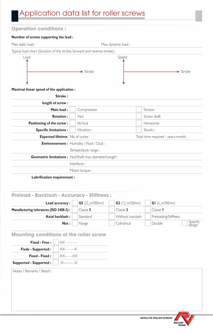
Established in 1970, ROLLVIS SA quickly started to focus exclusively on design, manufacturing and marketing of satellite roller screws under the tradmark «Rollvis swiss». Our products represent today the reference for high performan-ce linear motion applications. Our factory is equipped with the most powerful machines to achieve to lowest tolerances on roller screws from very small quantities to larger batches. Following a continuous improvement path, Rollvis SA never stopped in investing in new manufacturing technologies and and skills in business park of Plan-les-Ouates in Geneva. The Rollvis high tech spirit and the scale of the company have always been preserved to ensure the best reactivity, fl exibility and support to customer requirements. Five decades of experience combined with the latest technologies enable Rollvis screws to be the preferred choice in many demanding or complex applications for industrial, aerospace or defense applications and for any segment where the best is required.
Aircrafts
Helicopters
Unmannedvehicles
Launchers
Flight controls
Optronicsand Mechatronics
Lifting Equipment andpositioning systems
Special machines
Satellites
Telescops
Landing gears
Actuators
Defense
Roller screw expertise for a eronautics, space and Defense industry
Today ROLLVIS is certifi ed
ISO 9001 : 2015
EN 9100 : 2016
Certifi cation
Application data list for roller screws
Maximal linear speed of the application :
Stroke :
length of screw :
Main load : Compression Tension
Rotation : Nut Screw shaft
Positioning of the screw : Vertical Horizontal
Specifi c limitations : Vibration : Shocks :
Expected lifetime Nb of cycles : Total time required - years-month :
Environnement : Humidity / Fluid / Dust :
Temperature range :
Geometric limitations : Nut/Shaft max diameter/Length :
Interfaces :
Motor torque :
Lubrifi cation requirement :
Preload - Backlash - Accuracy - Stiffness :Lead accuracy : G5 (23_m/300mm) G3 (12_m/300mm) G1 (6_m/300mm)
Manufacturing tolerances (ISO 3408-3) : Classe 5 Classe 3 Classe 1
Axial backlash : Standard Without backlash Preloading/Stiffness
Nut : Flange Cylindrical Double Specifi c design
Mounting conditions of the roller screwFixed - Free : XX ––––––
Fixde - Supported : XX–––––X
Fixed - Fixed : XX––––XX
Supported - Supported : X––––––X
Operation conditions :
Number of screws supporting the lead :
Max static load : Max. dynamic load :
Typical load chart (function of the stroke, forward and reverse stroke) :
Load
Stroke
Speed
Stroke
Notes / Remarks / Sketch :
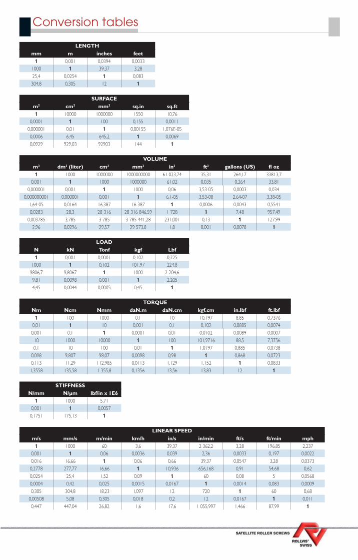
ROLLVIS SA 136, ch. du Pont-du-CentenaireCH-1228 Plan-les-OuatesGENEVA - SWITZERLANDCorrespondence: post box 590CH - 1212 GRAND-LANCY 1
Tél. +41 (0)22 706 90 40Fax +41 (0)22 706 90 49
Email : [email protected]: www.rollvis.com
Conversion tables
LENGTHmm m inches feet1 0,001 0,0394 0,0033
1000 1 39,37 3,2825,4 0,0254 1 0,083304,8 0,305 12 1
SURFACEm2 cm2 mm2 sq.in sq.ft1 10000 1000000 1550 10,76
0,0001 1 100 0,155 0,00110,000001 0,01 1 0,00155 1,076E-050,0006 6,45 645,2 1 0,00690,0929 929,03 92903 144 1
LOADN kN Tonf kgf Lbf1 0,001 0,0001 0,102 0,225
1000 1 0,102 101,97 224,89806,7 9,8067 1 1000 2 204,69,81 0,0098 0,001 1 2,2054,45 0,0044 0,0005 0,45 1
STIFFNESSN/mm N/µm lbf/in x 1E61 1000 5,71
0,001 1 0,00570,1751 175,13 1
VOLUMEm3 dm3 (liter) cm3 mm3 in3 ft3 gallons (US) fl oz1 1000 1000000 1000000000 61 023,74 35,31 264,17 33813,7
0,001 1 1000 1000000 61,02 0,035 0,264 33,810,000001 0,001 1 1000 0,06 3,53-05 0,0003 0,034
0,000000001 0,000001 0,001 1 6,1-05 3,53-08 2,64-07 3,38-051,64-05 0,0164 16,387 16 387 1 0,0006 0,0043 0,55410,0283 28,3 28 316 28 316 846,59 1 728 1 7,48 957,49
0,003785 3,785 3 785 3 785 441,28 231,001 0,13 1 127,992,96 0,0296 29,57 29 573,8 1,8 0,001 0,0078 1
TORQUENm Ncm Nmm daN.m daN.cm kgf.cm in.lbf ft.lbf1 100 1000 0,1 10 10,197 8,85 0,7376
0,01 1 10 0,001 0,1 0,102 0,0885 0,00740,001 0,1 1 0,0001 0,01 0,0102 0,0089 0,0007
10 1000 10000 1 100 101,9716 88,5 7,37560,1 10 100 0,01 1 1,0197 0,885 0,0738
0,098 9,807 98,07 0,0098 0,98 1 0,868 0,07230,113 11,29 112,985 0,0113 1,129 1,152 1 0,08331,3558 135,58 1 355,8 0,1356 13,56 13,83 12 1
LINEAR SPEEDm/s mm/s m/min km/h in/s in/min ft/s ft/min mph1 1000 60 3,6 39,37 2 362,2 3,28 196,85 2,237
0,001 1 0,06 0,0036 0,039 2,36 0,0033 0,197 0,00220,016 16,66 1 0,06 0,66 39,37 0,0547 3,28 0,03730,2778 277,77 16,66 1 10,936 656,168 0,91 54,68 0,620,0254 25,4 1,52 0,09 1 60 0,08 5 0,05680,0004 0,42 0,025 0,0015 0,0167 1 0,0014 0,083 0,00090,305 304,8 18,23 1,097 12 720 1 60 0,68
0,00508 5,08 0,305 0,018 0,2 12 0,0167 1 0,0110,447 447,04 26,82 1,6 17,6 1 055,997 1,466 87,99 1