Embed Size (px)
Citation preview

Converting a Kyosho Mini-Z to Spektrum Radio Gear
This is a short write up to attempt to help in the conversion of a Kyosho MiniZ from the standard
KO PROPO radio gear to Spektrum. I am happy to help if anyone has any question after reading
the attached write up. I have now converted three MR-02. Please go to Sat Lake MiniZ for
further discussion on the topic.
Getting started
A Losi MRX-3100 ESC/DSM: McRC part number LOSB0831 commonly used in Losi Micro
Trekker/Rock Crawlers will be used to provide the new ESC and Receiver for the MiniZ.
MR-02 and New Receiver
An old servo is also needed as the servo controller is integrated onto the same board as the rest of
the electronics that come with the stock MiniZ. Remove the electronics from the MRC3100 case
and the donor servo. It is a good idea to Bind the MRC3100 with your radio and test the servo
before starting cutting on them. Just help eliminate issues later.
Receiver and servo test before any wires are cut.
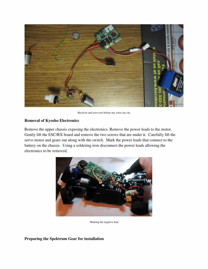
Removal of Kyosho Electronics
Remove the upper chassis exposing the electronics. Remove the power leads to the motor.
Gently lift the ESC/RX board and remove the two screws that are under it. Carefully lift the
servo motor and gears out along with the switch. Mark the power leads that connect to the
battery on the chassis. Using a soldering iron disconnect the power leads allowing the
electronics to be removed.
Marking the negative lead
Preparing the Spektrum Gear for installation

The hardest part of this entire process is converting the servo. If the intent is to install all of the
electronics under the upper chassis space is a premium. The next few steps are preparing the
electronics to be installed inside. If it is acceptable to leave the electronic on the top the servo
does not need to be solder to the MRC3100 board. Either way the servo motor and
potentiometer (pot) need to be connected to the servo board from your donor servo.
Example of both receiver installation methods

Donor servo wires prepped to be soldered on to the MRC3100 in the same place the connector in attached
Note the colors on the servo connector when connected to the MRC3100. Cut the servo wire
around an inch long and solder them to the prongs the connector used to connect to ensure the
same color wire is connected to the same prong (the servo wire should be connected in the
opposite direction to what the connector used to be).
This is also a good time to eliminate the switch if you are interested in doing so. The switch
comes attached to the MRC3100 is the same as what comes with the Kyosho so it can be
installed directly in the place that other switch was located.

Switch replaced with jumper
Remove the Pot from the gears Kyosho uses a two wire setup pin 1 and 2 are connected remove
this jumper with the soldering iron. Connect a new wire to pin 1. Set the donor servo board next
to the Kyosho Pot and remove the wires connected to the donor Pot and connect them to the
Kyosho Pot in the same order they were connected to the donor pot. The green wire is in the
middle. If the other two wires are connected incorrectly when the car is powered up the servo
will go to one side and stay there. If the happens flip the two outside wires. Connect the power
wires from the donor servo motor to the Kyosho servo motor

.
Kyosho Pot connections
New Pot wiring

Now the Servo assemble is ready to go back into the car. Because all of the electronics will be
installed in a tight space I normally coat the boards in liquid tape to prevent shorts later.
Clearancing the Main Chassis to fit the MRC3100 Board
Unfortunately the MRC3100 Board is slightly wider than the Kyosho board. This requires that
the main chassis have some material removed to allow for the wider board. Using a Dremel with
a cutting wheel remove the Kyosho board mounts and cut slots in the side wall. Be careful not to
cut in to the clips that hold the batteries in. I normally use an old battery to make sure I don’t go
too far.
Chaissis clearancing
Installing the MRC3100 inside the Chassis
Solder the MRC3100 power wires to the Battery terminals on the main Chassis marked
previously. Carefully fit all the electronics into the main chassis. Slip the orange and blue wire
through the upper chassis.
Electronic installation inside the chassis

Connect the orange wire to the red wire on the motor blue to black. Test radio gear. Throttle
channel will need to be reversed. If everything else is correct install the upper chassis and tie
rod. Enjoy running your MiniZ with your Spektrum radio gear that you drive everything else
with.
Performance
Before starting the conversion the Stock MR-02 was run on a Tamiya Mini speed checker as well
as weighted. The stock car could do 19 km/h fairly constantly and weighted 133.2 grams.
Testing the same car after the conversation it only does 17 km/h and weights 129.3 grams. For
what it is worth the other two cars I have converted will run the 19 km/h.
Enjoy!