Embed Size (px)
Citation preview

Converting the Motorola 42 to 50 MHz MT1000 or P200 to 50 to 54 MHz
Hardware mods by WB8VLC. RSS mods by WA1MIK
Transmitter and receiver mods to tune the entire band
and direct RSS frequency entry.
Revision 6: 31-Mar-2012
This revised document now has WA1MIK’s RSS modifications to allow direct
frequency entry from RSS. Hex-editing of the code plug is no longer necessary.
Go to this web page and download these documents.
http://www.repeater-builder.com/motorol ... index.html
Document 1: Radius P200 Low-band RF board information <Schematic
http://www.repeater-builder.com/motorola/genesis/pdfs/p200lb-elect.pdf
Document 2: Radius P200 Low-band Alignment Procedure <Service manual
http://www.repeater-builder.com/motorola/genesis/pdfs/p200lb-align.pdf
Document 3. Modifying the low-band P200/MT1000 RSS to cover the 6-
meter and 10-meter bands
http://www.repeater-builder.com/motorola/genesis/p200lb-6m-rss-mod.html
VCO CAPACITORS: Digi-Key 0805 chip caps
QTY: Reference designator value description
1 C1 VCO 7.5 pF Digi-Key 490-3598-1-ND
1 C2 VCO 18 pF Digi-Key 490-5533-1-ND
RF BOARD CAPACITORS. Digi-Key 0805 chip capacitors
QTY: Reference designator value description
1 C2 100pF Digi-Key 445-1329-1-ND
1 C8 68pF Digi-Key 478-1314-1-ND
1 C116 130pF Digi-Key 490-1602-1-ND
1 C117 75pF Digi-Key 490-1596-1-ND
4 C124, C125, C130, C131. 51pF Digi-Key 478-6214-1-ND
1 C126 20pF Digi-Key 478-3735-1-ND
1 C127 39pF Digi-Key 478-1311-1-ND
NOTE: RF BOARD C2 is not the same as VCO C2.
RF BOARD RESISTORS. Digi-Key 0805 chip resistors
QTY: reference designator value description
2 R108, R121 20 ohm Digi-Key P20ACT-ND
1 R106 33 ohm Digi-Key P33ACT-ND
1 R124 220 ohm Digi-Key P220ACT-ND

Note: data taken after several conversions shows that C1 optimum is 7.5 pF and
C2 optimum is ~17.5 pF, (18pF is fine) but you can go as low as 6.8 pF on C1 and
15 pF on C2 and as high as 9 pF for C1 and 20pF for C2 and coverage of the
entire ham band is still possible.
WHAT RSS should you be using?
For all MT1000 low band models with the LCD display: If you have the
MT1000 low band radio with the 2-digit LCD display, these models typically
came as 32 or 99 channel radios and from some information that others have sent
me they may all be capable of 99 channels. The correct RSS for all low band LCD
display models is regular MT1000.EXE; do not use the P200LB.EXE for any of
the low band LCD display model MT1000s.
For all P200 and MT1000, 6 channel models only: Use the P200LB.EXE only if
your radio is the 6-channel P200 or 6-channel MT1000 low band model.
NOTE: If the radio you have is not in the 42 to 50 split then stop right now as the
modifications to take a 36 to 42 split to either 6 meters or 10 meters are more in
depth and still being documented or worked on at this time. However; I have
successfully moved a 36 to 42 MHz split MT1000 to the 10-meter ham band with
great results but this is still being documented as the receiver pre-selector changes
are numerous.

Radio disassembly
1. Open the radio up by removing the 2 back cover screws and remove the 2 bottom
screws holding the front cover on. Loosen the 2 screws holding the battery plate
on; these are the larger screws near the center of the bottom plate. The other 2
screws are smaller and hold the front cover on. Don’t remove the 3 screws
holding the battery contacts. See Figure 1.0
Figure 1.0
2. Pull the front cover away from the back section and disconnect the speaker flex
cable.
3. Pull the radio away from and out of the LEXAN case by grasping the antenna and
pulling away from the Lexan case.
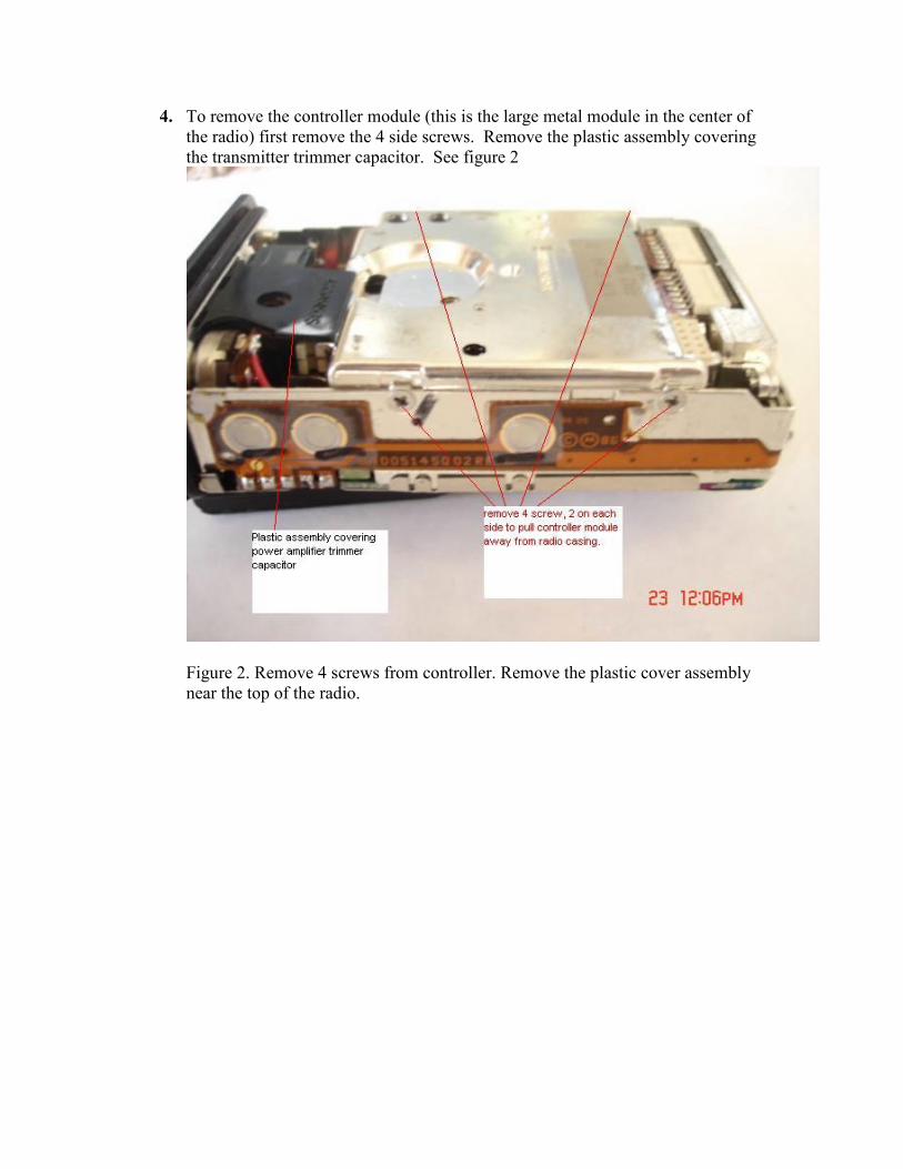
4. To remove the controller module (this is the large metal module in the center of
the radio) first remove the 4 side screws. Remove the plastic assembly covering
the transmitter trimmer capacitor. See figure 2
Figure 2. Remove 4 screws from controller. Remove the plastic cover assembly
near the top of the radio.

5. Next gently lift the controller module away from the main RF board/radio casing
by pulling the 2 top connectors off. Lift the board up at ~ 45 degree angle from
the top and remove the back side connector. See Figure 3.
Figure 3. Controller removal from radio

6. Carefully pull the controller up and slightly away from the main RF board. Using
a pair of tweezers or small blade screw driver push the 2 bottom connectors that
connect to the VCO up and away to free the controller board from the main board.
See figure 4.
Figure 4. Controller to VCO connector removal
7. Place the controller module aside.

8. Turn the radio over so the back metal shield/cover is facing up and remove the 4
screws securing the shield to the module. See figure 5.
Figure 5. Remove the 4 screws holding the RF back shield
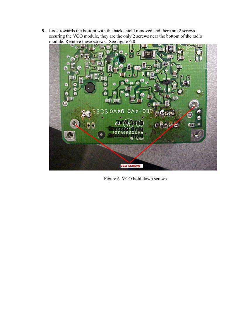
9. Look towards the bottom with the back shield removed and there are 2 screws
securing the VCO module, they are the only 2 screws near the bottom of the radio
module. Remove these screws. See figure 6.0
Figure 6. VCO hold down screws

Desoldering the VCO module from the main RF board
10. Using a solder sucker or some de-soldering wick remove the solder from the 11
pins shown in figure 7 and pull the VCO module away from the radios Main
Printed circuit board.
Figure 7. Unsoldering the VCO from main RF board
Once the VCO is removed from the main RF board, pull the snap on piece of the
3 piece VCO cover off of the VCO synthesizer assembly as follows. See figures
8A thru 8E.

Refer to figures 8A thru 8E, Remove the 2 VCO covers and set aside. Unsolder
the 10 pins from the controller part of the VCO module so that the RF section of
the VCO module can be separated from the VCO controller. Pull the VCO RF
section of the VCO board up and away from the remaining metal cover. The
result should be the RF VCO section in figure 8E.
Figure 8A. Remove the thinner clip on VCO cover by unclipping and lifting the
left side then lift the right side away and set this cover aside.
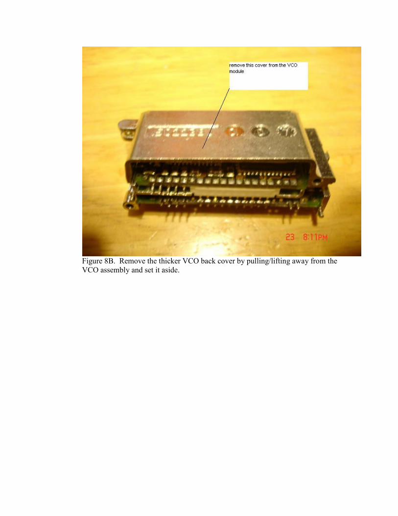
Figure 8B. Remove the thicker VCO back cover by pulling/lifting away from the
VCO assembly and set it aside.
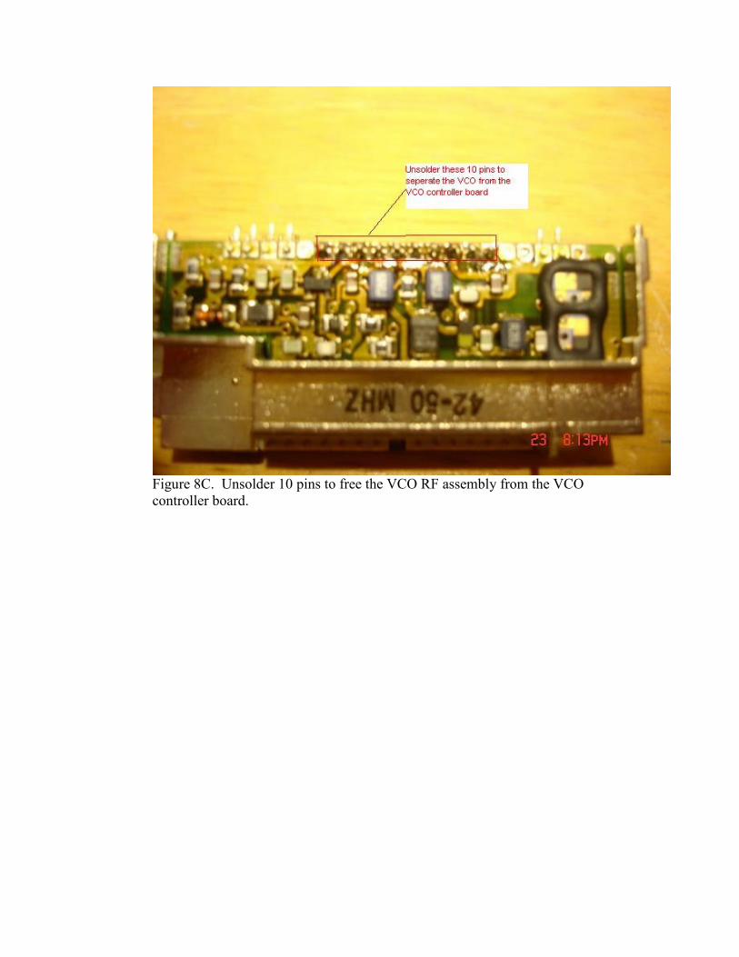
Figure 8C. Unsolder 10 pins to free the VCO RF assembly from the VCO
controller board.

Figure 8D. Pull the VCO controller board out and pull the VCO RF board up to
free each board from the metal VCO housing assembly.
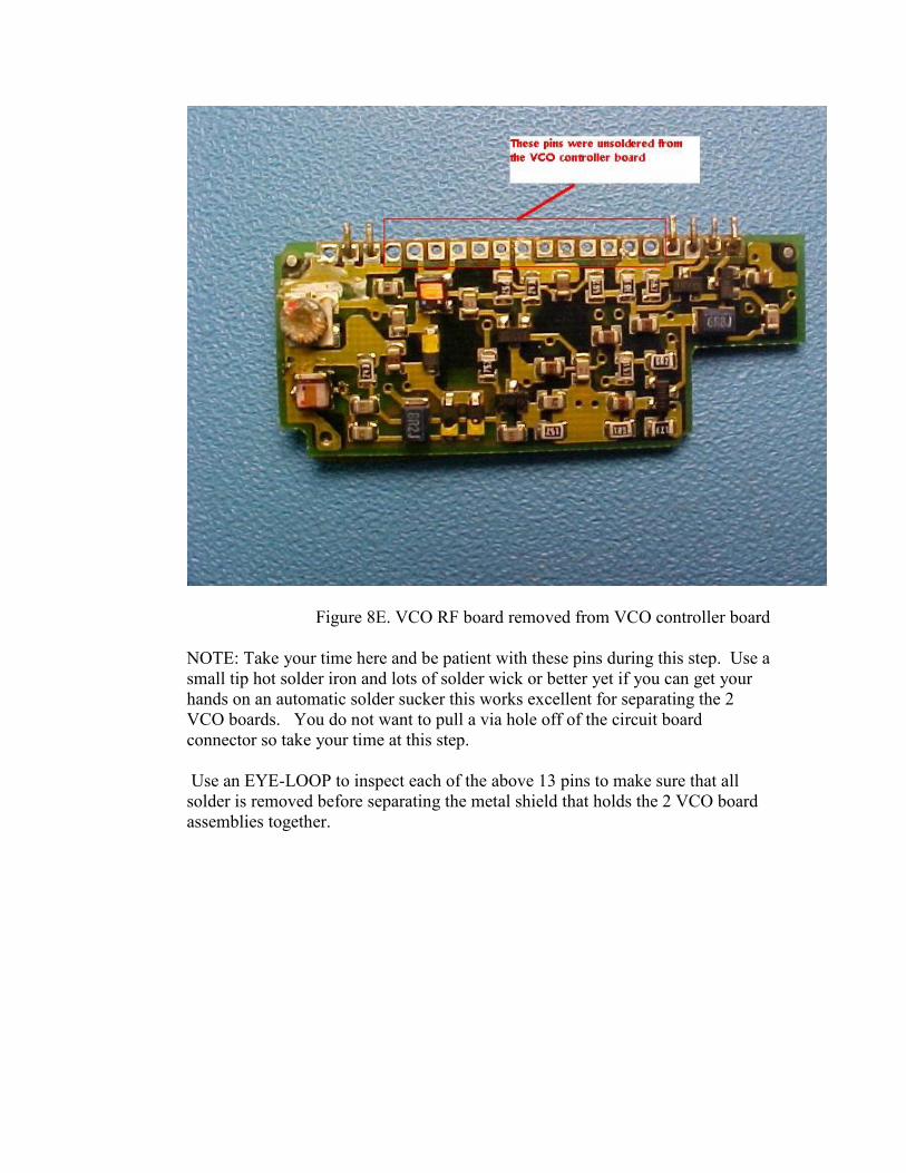
Figure 8E. VCO RF board removed from VCO controller board
NOTE: Take your time here and be patient with these pins during this step. Use a
small tip hot solder iron and lots of solder wick or better yet if you can get your
hands on an automatic solder sucker this works excellent for separating the 2
VCO boards. You do not want to pull a via hole off of the circuit board
connector so take your time at this step.
Use an EYE-LOOP to inspect each of the above 13 pins to make sure that all
solder is removed before separating the metal shield that holds the 2 VCO board
assemblies together.

Refer to figure 9. Remove the capacitor at the location labeled C1 in figure 4
and replace it with a 0805 size 7.5pF chip capacitor.
Figure 9. C1 location. Remove and replace the original capacitor with a 7.5pF
chip capacitor.

11. Refer to figure 10. Remove the capacitor at the location labeled C2 and replace it
with a 0805 size 18 pF chip capacitor.
Figure 10. C2 location. Replace with an 18pF chip capacitor.
12. Re-assemble the VCO in reverse order and solder it back in to the main RF
board. Screw the 2 VCO module hold down screws back in to the main RF board
to secure the VCO/synthesizer module.

Modifying the Transmitter and Receiver for full coverage
13. Place the radio on its front and remove the single top screw holding the RF
board to the radios case. See figure 11.
Figure 11. Remove the screw near the top center of the radio

14. Turn the radio over and unsolder the red lead from the power on/off switch. See
figure 12.
Figure 12. Unsolder the red lead connected to the Power on/off switch

15. Turn the radio over so the back side of the RF board is facing up.
16. Unsolder the center pin of the RF connector, the Ground tab holding the top
frame and the 2 U-clips holding the pins coming from the radios top multi pin
connector. See figure 13.
Figure 13. The 4 connections that are unsoldered to free the RF board from the
radio case/top connector assembly.

17. Gently lift the Main RF board away from the top radio case by pulling from the
top of the RF board. You may have to gently pry the top case away from the RF
board to dislodge the top 2 connector pins away from the U-clips. See figure 14
below.
Figure 14. RF board U clips pulled away from top connector pins
18. When the RF board U clips are free from the Top UDC connectors pins lift the
main RF board away from the radio case and set the radio case aside

19. See figure 15. With the RF board facing up, as in figure 14 below, locate inductor
L120 nearest the antenna. Note its location for the next step where the board is
flipped over.
Figure 15. Component side location of inductor L120

20. Flip the RF board over and unsolder inductor L120 at the 2 pins shown in figure
16 below.
Figure 16. Inductor L120, unsolder these 2 leads to remove.

21. Flip the RF board over and using a pair of tweezers, remove Inductor L120 from
the main RF board.
22. Remove 2 turns from inductor L120 and form this new inductor so the leads come
off in the same direction as the original part. This new modified inductor will
now have 8 turns.
23. Re-install modified inductor L120 back in its original position and solder it to the
RF board. See figure 17. Do not let the leads protrude more than about 5 mils on
the back side of the RF board, the leads should only stick out just enough to
solder to the original VIA holes.
Figure 17. Modified inductor L120 re-installed in board.

24. See figure 18. To gain access to Inductor L119 you must first unsolder and pull
off the shield covering L119 from the back side of the RF board.
Figure 18. Remove the shield covering L119 on the top side of the RF board.
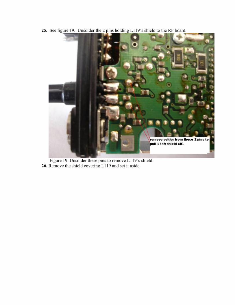
25. See figure 19. Unsolder the 2 pins holding L119’s shield to the RF board.
Figure 19. Unsolder these pins to remove L119’s shield.
26. Remove the shield covering L119 and set it aside.

27. See figure 20, Unsolder the 2 pins to remove inductor L119 from the RF board.
Figure 20. Unsolder these 2 pins to remove inductor L119.
28. Pull L119 off of the RF board and remove 1 turn from it. This modified part will
now have 7 turns.
29. Re-install modified L119 back in the RF board and solder the leads back in.
Do not let the leads protrude more than about 5 mils on the back side of the RF
board, the leads should only stick out just enough to solder to the original VIA
holes.
30. Re-install the shield over modified L119 and solder it to the RF board.

31. See figure 21. Locate the position of inductor L124.
Figure 21. Component side location of inductor L124

32. See figure 22. Unsolder L124’s pins from the backside of the RF board.
Figure 22. Unsolder these 2 pins to remove inductor L124.
33. Pull L124 off of the RF board and remove 1 turn, tin the leads just like was done
with L120 and L119 and re-install and solder this new part back into the RF
board.

RF BOARD PARTS CHANGES, SEE COMPONENT LOCATOR ON
NEXT PAGE.
RECEIVER /ANTENNA SWITCH CAPACITOR CHANGES
Download this document, #68P81085E58 for all of the following capacitor
and resistor component locations on the main RF board.
http://www.repeater-builder.com/motorola/genesis/pdfs/p200lb-elect.pdf
These component numbers are the schematic ref designators from the above
condensed manual, which applies to the P200LB or MT1000LB radios.
See page 5 of this condensed manual for the following parts locations.
1. Locate capacitor C8 and replace it with a 68 pF chip cap.
2. Locate capacitor C2 and replace it with a 100 pF chip.
3. Locate capacitors C131 and C130 and replace each with a 51 pF chip cap.
4. Locate capacitor C126 and replace it with a 20 pF chip cap.
5. Locate capacitor C127 and replace with a 39 pF chip cap.
TRANSMITTER CAPACITOR AND RESISTOR CHANGES.
Again see page 5 of document #68P81085E58, for component locations.
http://www.repeater-builder.com/motorola/genesis/pdfs/p200lb-elect.pdf
These component designators are the schematic ref designators from the
condensed manual above this applies to the P200LB or MT1000LB radios.
See page 5 of this condensed manual for the following parts locations.
TRANSMITTER POWER AMP CAPACITOR CHANGES
1. Locate Capacitors C125 and C124 and replace each with a 51 pF chip cap.
2. Locate C117 and replace with a 75 pF chip cap.
3. Locate C116 and replace with a 130 pF chip cap.
TRANSMITTER RESISTOR CHANGES FOR STABILITY
1. Locate R108 and R121 and replace each with a 20 ohm chip resistor.
2. Locate R106 and replace with a 33 ohm chip resistor.
3. Locate R124 and replace with a 220 ohm chip resistor.


34. Re-install the RF board back in the radio casing by placing the VCO end in first
then press the U-clips down so they make contact with the 2 top connector pins.
NOTE: You may need to cut back the bottom ends of the 2 U-clips off at around
half of their original length so that the 2 top connector pins can re-seat easily back
in to the U-clips. See figure 23.
Figure 23. Reinstalling the RF board U-clips into the top connector pins.

35. See figure 24. Screw the top center screw back in and re-solder the Antenna
connector center pin, the ground pin and the 2 top connector pins that connect to
the U- clips.
Figure 24. Re-solder the 4 RF board pins to the top assembly and screw the top
center screw in.

36. Resolder the red power lead to the On/Off switch as shown in figure 25.
Figure 25. re-solder the red power lead back to the ON/OFF switch.
37. Screw the back shield back in over the main RF board.
38. Re-assemble the controller module back in to the main RF board being sure to
place the back flex cable on first then slide the 2 bottom VCO connectors on and
drop the controller into the Main RF board while carefully attaching the 2 top
connectors to the controller module.
39. Re-assemble the radio into the LEXAN case and connect the front cover's speaker
mic flex cable back in and screw the radio back together.
***grounding the synthesizer lock detect line: ****
40. Some people have reported problems making the radio lock after the conversion
and with the display radios they have reported an error 88, which is an unlocked
VCO.
41. As a result you may need to ground the lock detect line, but only temporarily prior
to re-programming and retuning the VCOs.
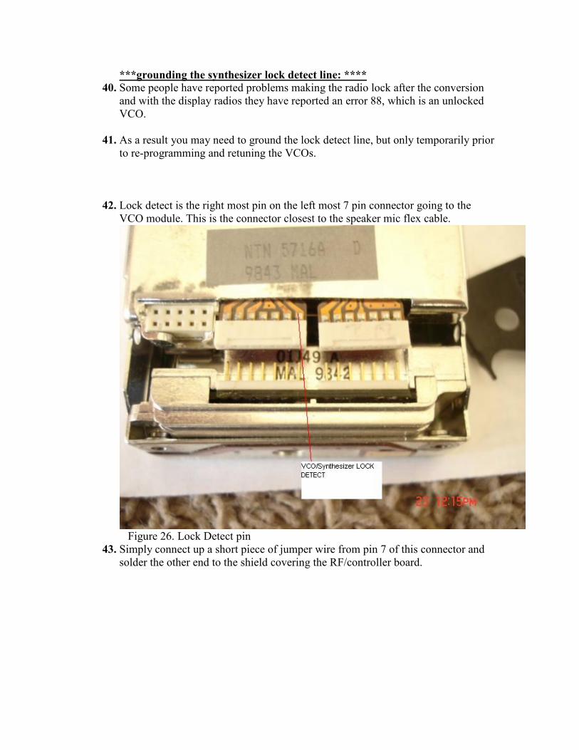
42. Lock detect is the right most pin on the left most 7 pin connector going to the
VCO module. This is the connector closest to the speaker mic flex cable.
Figure 26. Lock Detect pin
43. Simply connect up a short piece of jumper wire from pin 7 of this connector and
solder the other end to the shield covering the RF/controller board.

Radio Programming:
44. Remember for all 6 channel P200s and 6 channel MT1000s use RSS
P200LB.EXE. For all LCD display models of the MT1000 use RSS
MT1000.EXE.
45. Thanks to Bob Meister, WA1MIK, all that is needed is to modify the respective
RSS to accept frequencies up to 54 MHz.
RSS Programming Background: By Bob Meister WA1MIK
The 6-channel MT1000 low-band radio and the 6 channel P200 uses P200 programming
software P200LB.EXE. The display models of the 99 channel low band MT1000s use
MT1000.EXE. The low-band version of the Radio Service Software (RSS) for the
P200/MT1000 limits you to three ranges: 30.0 - 36.0 MHz, 36.0 - 42.0 MHz, or 42.0 -
50.0 MHz. You can change the range to be used by pressing F4 then F9 from the main
menu. When you change the range, the in-memory code plug will be cleared and you'll be
starting fresh, so make sure you choose the proper range for the radio you have before
you do any programming on it. Changing the range through software does not alter the
physical capabilities of the radio; you must still have the proper RF board in the radio to
operate on the range you select. They must match.
Before you make any changes to the program, be sure you make a backup copy of the
EXE file. Some hex-editors offer to do this every time you save changes, but I find it
better to make my own. Keep it in a safe place; you never know when you'll need it, and
if you make any mistakes hex-editing the file, you can always retrieve the backup and
start over. It's better to have a backup and not need it, than to need it and not have it.

Restrictions:
The modifications shown here were done with P200LB.EXE, Version D03.00.01, dated
01-Jun-90 and MT1000.EXE versions R03.00.00, 20-OCT-89 and R03.01.02, 1-Jun-94.
These versions seem to be the ones commonly found on the web.
All addresses and data bytes are in hexadecimal. Data bytes you'll be changing are shown
in bold red.
Changing the Band Limit:
The software frequency limitations are stored in two separate areas within the
P200LB.EXE and MT1000.EXE files. One specifies the lower limits; the other specifies
the upper limits. We're only concerned with the upper limit, which restricts frequency
data to 50.0 MHz. The values are stored as 8-byte, double precision, floating point
values. Hex Workshop (and probably any hex editor) can find the exact location (there's
only one occurrence of the double precision value 50.0). This value is stored starting at
hex address 3A122 for P200LB and address 3A619 for MT1000.EXE R03.00.00 and
address 3517C for MT1000 R03.01.02:
3A122: 00 00 00 00 00 00 49 90 for RSS P200.LB.exe
and
3A619: 00 00 00 00 00 00 49 40 for RSS R03.00.00 MT1000.EXE
3517C 00 00 00 00 00 00 49 40 for RSS R03.01.02 Mt1000.EXE
The above eight bytes represent a value of 50.0 decimal.
For P200LB.EXE change the byte at location 3A128 from 49 to 4B to change the upper
limit to 54.0 decimal. This lets you enter and edit transmit and receive frequencies from
42.0 through 54.0 MHz.
For display radios, which are the typical 99 channel radios, you need to use the
MT1000.EXE program, not P200LB.EXE.
In MT1000.EXE R03.00.00 change the byte at address $3A61F from 49 to 4B.
In MT1000.EXE R03.01.02 change the byte at address $35182 from 49 to 4B.
This moves the RSS recognized high limit to 54 MHz but the program actually lets
you go 2 MHz above this to 56 MHz in the MT1000 RSS.

Changing the Displayed Range:
One more cosmetic change really needs to be made. The list of acceptable frequency
ranges (on the F4, F9 menu mentioned above) should be changed to reflect the new band
upper limit. This is a simple ASCII null-terminated text string and Hex Workshop can
find the exact location for you (there's only one occurrence of the string "50.0"). This
string starts at hex address 39337:
For P200LB Change the byte at location 3933F from 30 to 34 to change the displayed
text to become "42.0 - 54.0 MHz".
For 99 channel radios you need to use MT1000.EXE not P200LB.EXE.
So to change what the MT1000.EXE RSS displays you need to change the byte at
address $397BF from 30 to 34 in MT1000.exe version R03.00.00 and for version
R03.01.02 the byte at $3438A needs to be changed from 30 to 34.
Save the file and you should be good to go. No more hex-editing of the radio's code plug
or worrying about reviewing the frequency values in RSS. Start RSS, read the code plug,
make your changes, save the code plug to disk, and write the code plug to the radio

Connecting to the radio at the antenna terminal
You can make a homebrew antenna connector by using a short length of 50 ohm
coax and a cutoff SMA connector.
Attach a suitable connector such as a BNC to one end of this cable.
Form the other end into pigtails, solder the center lead of this pigtail to the outer
side of the SMA male connector and screw this a few turns into the radios antenna
connector.
Attach the shield of this 50 ohm coax pigtail end to the top screw that covers the
radios UDC connector making sure to obtain a good ground at this screw.
See figure 27 below for an example using a small brass strap as the ground
connection point of the pigtail connector.
Figure 27. Home-made antenna cable.

Transmitter Alignment: See figure 28 below. Use document >
http://www.repeater-builder.com/motorola/genesis/pdfs/p200lb-align.pdf
When tuning C159 and C115 use a long insulated tool so as not to short to the
radio case.
Use a good fully charged battery prior to PA alignment, with an ~ 10.5 volt fully
charged pack you should measure ~ 7 watts, +/- 0.6 watt across the band when
finished.
A method of tuning that worked for me was to tune C159 for best power at your
highest TX frequency and then adjust C115 for best balance of TX power across
the band while staying around 7.0 watts ~ +/- 0.6 watt up to 53.99 MHz.
Also be aware that the maximum Tx current will be just over 2.1 amps due to the
power transistor's efficiencies degrading above 50 MHz and the stability changes
made in the transmitter to extend operation to 53.99 MHz.
I was able to get 6.4 to 7.6 watts power flatness across my operating range from
51.10 to 53.99 MHz on Transmit.
FIGURE 28 Transmitter trimmer cap locations.

RECEIVER ALIGNMENT/LOCAL OSCILLATOR INJECTION COILS
See page 7 of the following document for the locations of L12 and L13.
http://www.repeater-builder.com/motorola/genesis/pdfs/p200lb-align.pdf
1. Align the receiver across your operating range by the method in the above
document. Basically you only need to tune L12 and L13, the local oscillator
injection coils, for best sensitivity across your operating range.
2. Typical 12 dB SINAD measurements will be 0.35 uV or less.
Troubleshooting:
If you have any problems making the radio lock after the conversion you will
need to temporarily ground the lock detect line if you can’t reprogram the radio
after any VCO tweaks.
This step should only be done temporarily if your VCO will not lock at the band
edges in TX or RX or both and you cannot reprogram the radio.
Temporarily grounding the lock detect line before reprogramming a radio that is
beeping or on a LCD radio that is displaying the numbers 88 will aid in
reprogramming.
Lock detect is the right most pin on the left most 7 pin connector going to the
VCO module. This is the connector closest to the speaker mic's flex cable.
Simply connect up a short piece of jumper wire from pin 7 of this connector and
solder the other end to the shield covering the RF/controller board.
If needed, make VCO capacitor modifications by using ~0.5 pF smaller capacitors if
needed to get higher frequency operation and then reprogram the radio. Once the
radios is re-programmed remove the lock detect shorting wire and check for RX and
TX VCO lock at all frequencies.
WB8VLC/7 hardware mods and Bob Meister WA1MIK RSS mods