Embed Size (px)
Citation preview
FR
EN
Owner’s Manual
Mode d’emploi
DTX502DRUM TRIGGER MODULE
CONVERTISSEUR DE SONS POUR BATTERIE
English
Fran
çais
2 DTX502 Owner’s Manual
ContentsWelcome ......................................................................... 6
Product Manuals............................................................ 6
SetupFirst Steps ...................................................................... 7
Quick Start Guide .......................................................... 8
Choosing Drum Sounds.......................................................... 8Playing Along with a Song....................................................... 8Practicing with the Metronome ................................................ 8Practicing in Training Mode ..................................................... 9Recording Your Performances................................................. 9
Component Names & Functions ................................ 10
Control Panel..........................................................................10Rear Panel .............................................................................11
Setting Up for Sound................................................... 12
Connecting the Power ........................................................... 12Connecting Headphones or Speakers .................................. 12Connecting a Music Player.................................................... 12Turning On the Drum Module ................................................ 13Initial Setup ........................................................................... 13Quickly Disabling Auto Power-Off .......................................... 13Turning Off the Drum Module ................................................ 14Restoring the Default Settings............................................... 14
Basic TechniquesBasic DTX502 Operations ........................................... 15
Striking the Drum Pads ............................................... 16
Snare..................................................................................... 16Hi-hats................................................................................... 17Cymbals ................................................................................ 18
Selecting & Playing a Kit............................................. 19
Selecting a Kit ....................................................................... 19Adjusting Pad Sensitivity ....................................................... 19Balancing Instrument Volumes.............................................. 19
Building Your Own Unique Kits ................................. 20
Assigning Voices to Instruments ........................................... 21Tuning & Changing Cymbal Sizes ......................................... 22Customizing Instrument Voices............................................. 23Adjusting Instrument Volumes............................................... 24Adjusting the Stereo Panning of Instruments ........................ 24
Saving Customized Kits.............................................. 25
Performing with a Song .............................................. 26
Selecting a Song ................................................................... 26Adjusting the Song Volume ................................................... 26Adjusting the Song Tempo .................................................... 27Muting a Song’s Drum Parts ................................................. 27Looping a Song ..................................................................... 28Playing with Count-In ............................................................ 28Playing Pad Songs ................................................................ 29
Using the Metronome .................................................. 31
Starting & Stopping ............................................................... 31Adjusting the Tempo.............................................................. 31Setting the Overall Volume.................................................... 31
Customizing the Metronome ...................................... 32
Selecting a Click Set ............................................................. 32Setting the Tempo ................................................................. 33Setting the Time Signature.................................................... 33Setting the Timer ................................................................... 33Setting Individual Volumes .................................................... 34Changing Sounds for All Subdivisions .................................. 34Changing Sounds for Individual Subdivisions ....................... 35Tuning Click-Set Sounds ....................................................... 36Tapping the Tempo on the Pads............................................ 36
Storing a Customized Click Set ................................. 37
Practicing in Training Mode ....................................... 38
1. Groove Check .................................................................... 382. Rhythm Gate ..................................................................... 403. Measure Break.................................................................. 414. Tempo Up/Down................................................................ 425. Change Up........................................................................ 446. Pad Gate ........................................................................... 467. Part Mute ........................................................................... 478. Fast Blast .......................................................................... 49
Recording Your Performances................................... 51
Getting Ready ....................................................................... 51Recording.............................................................................. 52Playing Back a Performance ................................................. 52Naming a User Song............................................................. 53Deleting a Recorded Performance ........................................ 54
Advanced TechniquesSetting Parameters using Menu Mode ...................... 55
Setting Procedure.................................................................. 56Storing your settings.............................................................. 56
Integrating Separately Sold Accessories.................. 76
Adding a PCY90AT Cymbal Pad ........................................... 76Using a KU100 Kick Unit as a Kick Pedal ............................. 76
Integrating Electronic & Acoustic Drums ................. 77
Adding Drum Pads to an Acoustic Drum Set ........................ 77Playing the DTX502 Using Acoustic Drums.......................... 77Mounting the DTX502 on a Hi-Hat Stand.............................. 78
Connecting to a Computer ......................................... 79
Making Connections.............................................................. 79DTX502 Reference Manual................................................... 79
ReferenceError Messages............................................................ 80
Troubleshooting .......................................................... 81
Data List ....................................................................... 83
Specifications .............................................................. 88
Index ............................................................................. 89
SPECIAL MESSAGE SECTIONThis product utilizes batteries or an external power supply (adapter). DO This product may also use “household” type batteries. Some of these
NOT connect this product to any power supply or adapter other than one described in the manual, on the name plate, or specifically recom-mended by Yamaha.This product should be used only with the components supplied or; a cart, rack, or stand that is recommended by Yamaha. If a cart, etc., is used, please observe all safety markings and instructions that accom-pany the accessory product.
SPECIFICATIONS SUBJECT TO CHANGE: The information contained in this manual is believed to be correct at the time of printing. However, Yamaha reserves the right to change or modify any of the specifications without notice or obligation to update existing units.
This product, either alone or in combination with an amplifier and head-phones or speaker/s, may be capable of producing sound levels that could cause permanent hearing loss. DO NOT operate for long periods of time at a high volume level or at a level that is uncomfortable. If you experience any hearing loss or ringing in the ears, you should consult an audiologist. IMPORTANT: The louder the sound, the shorter the time period before damage occurs.
NOTICE: Service charges incurred due to a lack of knowledge relating to how a function or effect works (when the unit is operating as designed) are not covered by the manufacturer’s warranty, and are therefore the owners responsibility. Please study this manual carefully and consult your dealer before requesting service.
ENVIRONMENTAL ISSUES:Yamaha strives to produce products that are both user safe and environ-mentally friendly. We sincerely believe that our products and the produc-tion methods used to produce them, meet these goals. In keeping with both the letter and the spirit of the law, we want you to be aware of the following:
Battery Notice: This product MAY contain a small non-rechargeable battery which (if applicable) is soldered in place. The average life span of this type of bat-tery is approximately five years. When replacement becomes necessary, contact a qualified service representative to perform the replacement.
may be rechargeable. Make sure that the battery being charged is a rechargeable type and that the charger is intended for the battery being charged.
When installing batteries, never mix old batteries with new ones, and never mix different types of batteries. Batteries MUST be installed cor-rectly. Mismatches or incorrect installation may result in overheating and battery case rupture.
Warning: Do not attempt to disassemble, or incinerate any battery. Keep all batter-ies away from children. Dispose of used batteries promptly and as regu-lated by the laws in your area. Note: Check with any retailer of household type batteries in your area for battery disposal information.
Disposal Notice: Should this product become damaged beyond repair, or for some reason its useful life is considered to be at an end, please observe all local, state, and federal regulations that relate to the disposal of products that contain lead, batteries, plastics, etc. If your dealer is unable to assist you, please contact Yamaha directly.
NAME PLATE LOCATION: The name plate is located on the bottom of the product. The model num-ber, serial number, power requirements, etc., are located on this plate. You should record the model number, serial number, and the date of pur-chase in the spaces provided below and retain this manual as a perma-nent record of your purchase.
Model
Serial No.
Purchase Date
PLEASE KEEP THIS MANUAL92-BP (bottom)
1. IMPORTANT NOTICE: DO NOT MODIFY THIS UNIT! antee that interference will not occur in all installations. If this product
FCC INFORMATION (U.S.A.)
This product, when installed as indicated in the instructions contained in this manual, meets FCC requirements. Modifications not expressly approved by Yamaha may void your authority, granted by the FCC, to use the product.
2. IMPORTANT: When connecting this product to accessories and/or another product use only high quality shielded cables. Cable/s sup-plied with this product MUST be used. Follow all installation instruc-tions. Failure to follow instructions could void your FCC authorization to use this product in the USA.
3. NOTE: This product has been tested and found to comply with the requirements listed in FCC Regulations, Part 15 for Class “B” digital devices. Compliance with these requirements provides a reasonable level of assurance that your use of this product in a residential envi-ronment will not result in harmful interference with other electronic devices. This equipment generates/uses radio frequencies and, if not installed and used according to the instructions found in the users manual, may cause interference harmful to the operation of other electronic devices. Compliance with FCC regulations does not guar-
is found to be the source of interference, which can be determined by turning the unit “OFF” and “ON”, please try to eliminate the problem by using one of the following measures:Relocate either this product or the device that is being affected by the interference.Utilize power outlets that are on different branch (circuit breaker or fuse) circuits or install AC line filter/s.In the case of radio or TV interference, relocate/reorient the antenna. If the antenna lead-in is 300 ohm ribbon lead, change the lead-in to co-axial type cable.If these corrective measures do not produce satisfactory results, please contact the local retailer authorized to distribute this type of product. If you can not locate the appropriate retailer, please contact Yamaha Corporation of America, Electronic Service Division, 6600 Orangethorpe Ave, Buena Park, CA90620The above statements apply ONLY to those products distributed by Yamaha Corporation of America or its subsidiaries.
* This applies only to products distributed by YAMAHA CORPORATION OF AMERICA. (class B)
Responsible Party : Yamaha Corporation of America This device complies with Part 15 of the FCC Rules.
COMPLIANCE INFORMATION STATEMENT (DECLARATION OF CONFORMITY PROCEDURE)
Address : 6600 Orangethorpe Ave., Buena Park, Calif. 90620Telephone : 714-522-9011
Type of Equipment : DRUM TRIGGER MODULEModel Name : DTX502
Operation is subject to the following two conditions:1) this device may not cause harmful interference, and2) this device must accept any interference received including interfer-
ence that may cause undesired operation.See user manual instructions if interference to radio reception is suspected.
* This applies only to products distributed by YAMAHA CORPORATION OF AMERICA. (FCC DoC)
DTX502 Owner’s Manual 3
4
PRECAUTIONSPLEASE READ CAREFULLY BEFORE PROCEEDING
Please keep this manual in a safe and handy place for future reference.
WARNINGAlways follow the basic precautions listed below to avoid the possibility of serious injury or even death from electrical shock, short-circuiting, damages, fire or other hazards. These precautions include, but are not limited to, the following:
• Do not place the power cord near heat sources such as heaters or radiators. Also, do not excessively bend or otherwise damage the cord, or place heavy objects on it.
• Only use the voltage specified as correct for the instrument. The required voltage is printed on the name plate of the instrument.
• Use the specified adaptor (page 88) only. Using the wrong adaptor can result in damage to the instrument or overheating.
• Check the electric plug periodically and remove any dirt or dust which may have accumulated on it.
• This instrument contains no user-serviceable parts. Do not open the instrument or attempt to disassemble or modify the internal components in any way. If it should appear to be malfunctioning, discontinue use immediately and have it inspected by qualified Yamaha service personnel.
• Do not expose the instrument to rain, use it near water or in damp or wet conditions, place on it any containers (such as vases, bottles or glasses) containing liquids which might spill into any openings. If any liquid such as water seeps into the instrument, turn off the power immediately and unplug the power cord from the AC outlet. Then have the instrument inspected by qualified Yamaha service personnel.
• Never insert or remove an electric plug with wet hands.
• Do not put burning items, such as candles, on the unit. A burning item may fall over and cause a fire.
• When one of the following problems occur, immediately turn off the power switch and disconnect the electric plug from the outlet. Then have the device inspected by Yamaha service personnel.- The power cord or plug becomes frayed or damaged.- It emits unusual smells or smoke.- Some object has been dropped into the instrument.- There is a sudden loss of sound during use of the instrument.
CAUTIONAlways follow the basic precautions listed below to avoid the possibility of physical injury to you or others, or damage to the instrument or other property. These precautions include, but are not limited to, the following:
• Do not connect the instrument to an electrical outlet using a multiple-connector. Doing so can result in lower sound quality, or possibly cause overheating in the outlet.
• When removing the electric plug from the instrument or an outlet, always hold the plug itself and not the cord. Pulling by the cord can damage it.
• Remove the electric plug from the outlet when the instrument is not to be used for extended periods of time, or during electrical storms.
• Do not place the instrument in an unstable position where it might accidentally fall over.
• Before moving the instrument, remove all connected cables, to prevent damage to the cables or injury to anyone who might trip over them.
• When setting up the product, make sure that the AC outlet you are using is easily accessible. If some trouble or malfunction occurs, immediately turn off the power switch and disconnect the plug from the outlet. Even when the power switch is turned off, electricity is still flowing to the product at the minimum level. When you are not using the product for a long time, make sure to unplug the power cord from the wall AC outlet.
• Use only the stand/rack specified for the instrument. When attaching the stand or rack, use the provided screws only. Failure to do so could cause damage to the internal components or result in the instrument falling over.
Power supply/AC power adaptor
Do not open
Water warning
Fire warning
If you notice any abnormality
Power supply/AC power adaptor Location
DTX502 Owner’s ManualDMI-5 1/2
• Before connecting the instrument to other electronic components, turn off the power for all components. Before turning the power on or off for all components, set all volume levels to minimum.
• Be sure to set the volumes of all components at their minimum levels and gradually raise the volume controls while playing the instrument to set the desired listening level.
• Do not insert a finger or hand in any gaps on the instrument.• Never insert or drop paper, metallic, or other objects into the gaps on the
panel. This could cause physical injury to you or others, damage to the instrument or other property, or operational failure.
• Do not rest your weight on, or place heavy objects on the instrument, and do not use excessive force on the buttons, switches or connectors.
• Do not use the instrument/device or headphones for a long period of time at a high or uncomfortable volume level, since this can cause permanent hearing loss. If you experience any hearing loss or ringing in the ears, consult a physician.
Always turn the power off when the instrument is not in use. Even when the [ ] (Standby/On) switch is in standby status (display is off), electricity is still flowing to the instrument at the minimum level. When you are not using the instrument for a long time, make sure you unplug the power cord from the wall AC outlet.
NOTICE
To avoid the possibility of malfunction/ damage to the prod-uct, damage to data, or damage to other property, follow the notices below.
Handling and Maintenance
• Do not use the instrument in the vicinity of a TV, radio, stereo equipment, mobile phone, or other electric devices. Otherwise, the instrument, TV, or radio may generate noise.
• Do not expose the instrument to excessive dust or vibra-tions, or extreme cold or heat (such as in direct sunlight, near a heater, or in a car during the day) to prevent the possibility of panel disfiguration, damage to the internal components or unstable operation.
• Do not place vinyl, plastic or rubber objects on the instrument, since this might discolor the panel or key-board.
• When cleaning the instrument, use a soft, dry cloth. Do not use paint thinners, solvents, cleaning fluids, or chemical-impregnated wiping cloths.
Information
About copyrights
• Copying of the commercially available musical data including but not limited to MIDI data and/or audio data is strictly prohibited except for your personal use.
• This product incorporates and bundles computer pro-grams and contents in which Yamaha owns copyrights or with respect to which it has license to use others’ copyrights. Such copyrighted materials include, without limitation, all computer software, style files, MIDI files, WAVE data, musical scores and sound recordings. Any unauthorized use of such programs and contents out-side of personal use is not permitted under relevant laws. Any violation of copyright has legal conse-quences. DON’T MAKE, DISTRIBUTE OR USE ILLE-GAL COPIES.
About this manual
• The illustrations and LCD screens as shown in this manual are for instructional purposes only, and may appear somewhat different from those on your instru-ment.
• The company names and product names in this manual are the trademarks or registered trademarks of their respective companies.
Connections Handling caution
Yamaha cannot be held responsible for damage caused by improper use or modifications to the instrument, or data that is lost or destroyed.
Optional Pads
Within this Owner’s Manual, the optional external pads that may be connected to the drum module are referred to by model name. Please note that these model names were up-to-date as of printing of this manual. Details regarding any subse-quently released models will be made available via the following web site.
http://www.yamaha.com/
DTX502 Owner’s Manual 5DMI-5 2/2
6
WelcomeThank you for purchasing a Yamaha DTX502 Electronic Drum Module.
In order to get the most out of your new instrument, please be sure to read this owner’s manual carefully.
And after doing so, be sure to store this manual in a safe place
so that you can refer back to it again as needed.
Owner’s Manual (this booklet)—Setup, Basic Techniques, Advanced Techniques, and Reference sections.
Setup: Describes how to get your DTX502 drum module set up for playing and making initial settings.
Basic Techniques: Describes the basic techniques used when operating and playing the DTX502.
Advanced Techniques: Describes the setting of parameters and other more advanced modes of use.
Reference: Describes troubleshooting techniques and contains other reference materials.
Reference Manual*: The Reference Manual is not bundled together with the drum module. See page 79 for more details.
The Reference Manual for the DTX502 is made available as a PDF document and contains the following.
• Instructions on how to transfer kit data, song data, and audio data from your computer to the drum module.• Reference material that will prove useful when making music using the drum module and a computer• MIDI-related reference information
Using PDF Manuals The Reference Manual for your DTX502 is made available in digital format as a PDF document. As such, a computer and suitable software will be required in order to read it. We recommend that Adobe® Reader® be used for this purpose as it allows you to quickly and easily search for keywords, to print out specific sections, and to conveniently jump from page to page by clicking embedded links. Keyword searching and link-based navigation in particular are extremely useful functions available only with digital-type documents. The most-recent version of Adobe® Reader® can be downloaded from the following web page.
http://www.adobe.com/products/reader/
Product Manuals
Package contents
• Power adaptor* May not be included depending on your particular area. Please check with your Yamaha dealer.
• Module holder• Module-holder screw (x2) • Owner’s Manual (this booklet)
DTX502 Owner’s Manual
Setup
Setup
First Steps
7
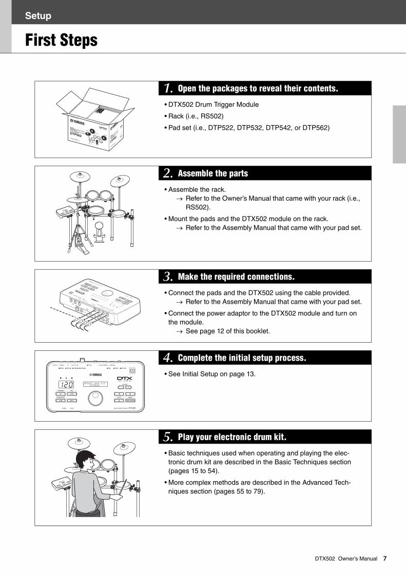
DTX502 Owner’s Manual1. Open the packages to reveal their contents.
• DTX502 Drum Trigger Module
• Rack (i.e., RS502)
• Pad set (i.e., DTP522, DTP532, DTP542, or DTP562)
2. Assemble the parts
• Assemble the rack. Refer to the Owner’s Manual that came with your rack (i.e.,
RS502).
• Mount the pads and the DTX502 module on the rack. Refer to the Assembly Manual that came with your pad set.
3. Make the required connections.
• Connect the pads and the DTX502 using the cable provided. Refer to the Assembly Manual that came with your pad set.
• Connect the power adaptor to the DTX502 module and turn on the module.
See page 12 of this booklet.
4. Complete the initial setup process.
• See Initial Setup on page 13.
5. Play your electronic drum kit.
• Basic techniques used when operating and playing the elec-tronic drum kit are described in the Basic Techniques section (pages 15 to 54).
• More complex methods are described in the Advanced Tech-niques section (pages 55 to 79).
120Select your kit DtX562K
Setup
Quick Start Guide
8
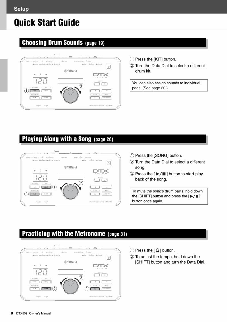
DTX502 Owner’s Manualq Press the [KIT] button.
w Turn the Data Dial to select a different drum kit.
q Press the [SONG] button.
w Turn the Data Dial to select a different song.
e Press the [ ] button to start play-back of the song.
q Press the [ ] button.
w To adjust the tempo, hold down the [SHIFT] button and turn the Data Dial.
Choosing Drum Sounds (page 19)
You can also assign sounds to individual pads. (See page 20.)
Playing Along with a Song (page 26)
To mute the song’s drum parts, hold down the [SHIFT] button and press the [ ] button once again.
Practicing with the Metronome (page 31)
120
qw
120
e
qw
120
w
w
q
Setup
Quick Start Guide
9
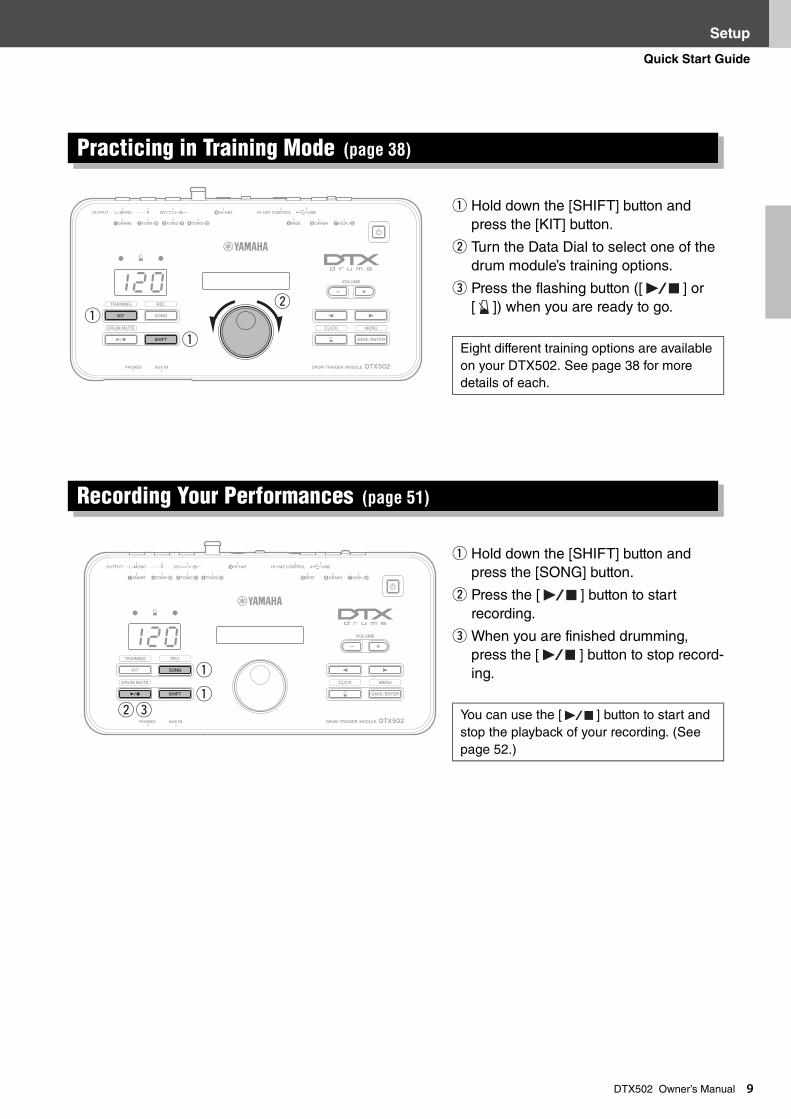
DTX502 Owner’s Manualq Hold down the [SHIFT] button and press the [KIT] button.
w Turn the Data Dial to select one of the drum module’s training options.
e Press the flashing button ([ ] or [ ]) when you are ready to go.
q Hold down the [SHIFT] button and press the [SONG] button.
w Press the [ ] button to start recording.
e When you are finished drumming, press the [ ] button to stop record-ing.
Practicing in Training Mode (page 38)
Eight different training options are available on your DTX502. See page 38 for more details of each.
Recording Your Performances (page 51)
You can use the [ ] button to start and stop the playback of your recording. (See page 52.)
120
q
qw
120
we
q
q
Setup
1
Component Names & Functions
0
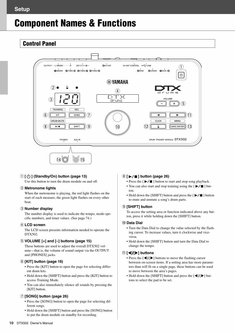
DTX502 Owner’s Manualq [ ] (Standby/On) button (page 13)
Use this button to turn the drum module on and off.
w Metronome lights
When the metronome is playing, the red light flashes on the start of each measure; the green light flashes on every other beat.
e Number display
The number display is used to indicate the tempo, mode-spe-cific numbers, and timer values. (See page 74.)
r LCD screen
The LCD screen presents information needed to operate the DTX502.
t VOLUME [+] and [–] buttons (page 15)
These buttons are used to adjust the overall DTX502 vol-ume—that is, the volume of sound output via the OUTPUT and [PHONES] jacks.
y [KIT] button (page 19)
• Press the [KIT] button to open the page for selecting differ-ent drum kits.
• Hold down the [SHIFT] button and press the [KIT] button to access Training Mode.
• You can also immediately silence all sounds by pressing the [KIT] button.
u [SONG] button (page 26)
• Press the [SONG] button to open the page for selecting dif-ferent songs.
• Hold down the [SHIFT] button and press the [SONG] button to put the drum module on standby for recording.
i [ ] button (page 26)
• Press the [ ] button to start and stop song playback.• You can also start and stop training using the [ ] but-
ton. • Hold down the [SHIFT] button and press the [ ] button
to mute and unmute a song’s drum parts.
o [SHIFT] button
To access the setting area or function indicated above any but-ton, press it while holding down the [SHIFT] button.
!0 Data Dial
• Turn the Data Dial to change the value selected by the flash-ing cursor. To increase values, turn it clockwise and vice-versa.
• Hold down the [SHIFT] button and turn the Data Dial to change the tempo.
!1 [<]/[>] buttons
• Press the [<]/[>] buttons to move the flashing cursor between on-screen items. If a setting area has more parame-ters than will fit on a single page, these buttons can be used to move between the area’s pages.
• Hold down the [SHIFT] button and press the [<]/[>] but-tons to select the pad to be set.
Control Panel
120 wxyz{|} drums
q
te
wr
y u
i o !0
!1
!2 !3
!4 !5
Setup
Component Names & Functions
11
DTX502 Owner’s Manual!2 [ ] button (page 31)
• Press the [ ] button to start and stop the built-in metro-nome.
• In Training Mode, you can use the [ ] button to start and stop practice sessions.
• Hold down the [SHIFT] button and press the [ ] button to access the area for advanced metronome settings.
!3 [SAVE/ENTER] button
• Press the [SAVE/ENTER] button when you want to store your data.
• Hold down the [SHIFT] button and press the [SAVE/ENTER] button to access Menu Mode for advanced DTX502 settings.
!4 [PHONES] jack
Use this standard audio jack to connect a pair of stereo head-phones.
!5 [AUX IN] jack (page 12)
The Auxiliary Input stereo mini-jack is used to input audio from an external source into the DTX502. For example, you can use this jack to connect a portable music player, a CD player, or another similar device and play along with your favorite tunes.
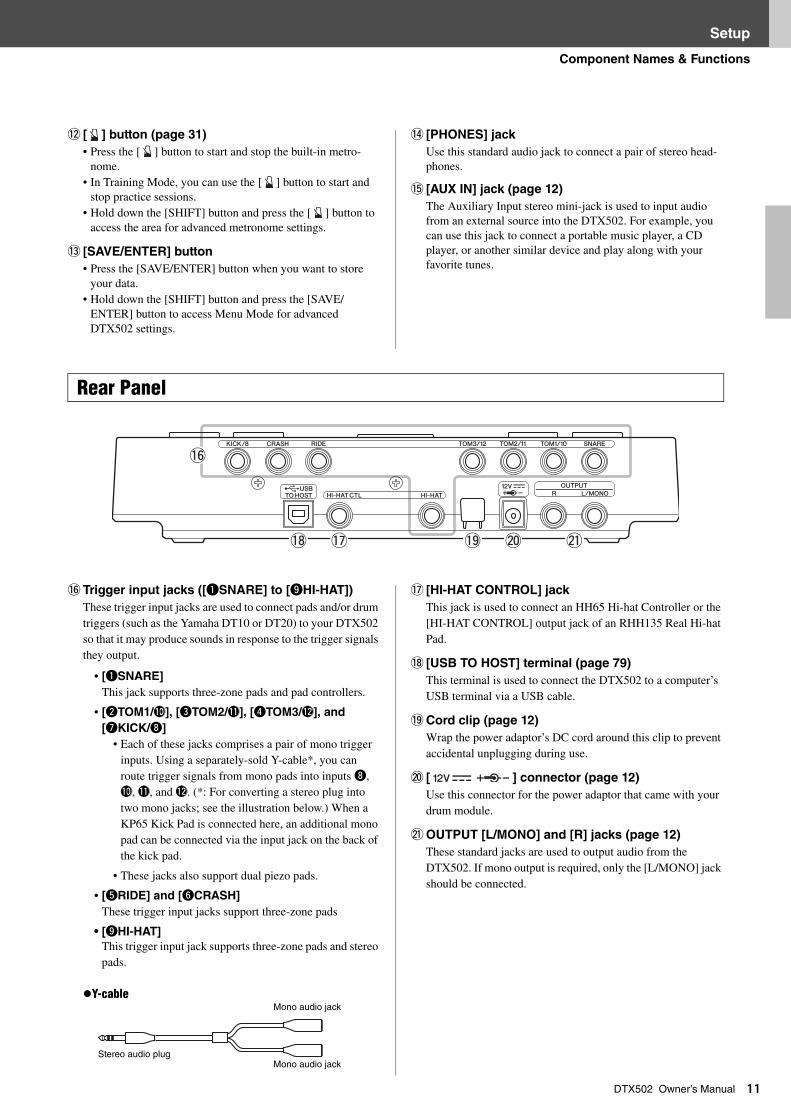
!6 Trigger input jacks ([qSNARE] to [oHI-HAT])
These trigger input jacks are used to connect pads and/or drum triggers (such as the Yamaha DT10 or DT20) to your DTX502 so that it may produce sounds in response to the trigger signals they output.
• [qSNARE]
This jack supports three-zone pads and pad controllers.
• [wTOM1/!0], [eTOM2/!1], [rTOM3/!2], and
[uKICK/i]
• Each of these jacks comprises a pair of mono trigger inputs. Using a separately-sold Y-cable*, you can route trigger signals from mono pads into inputs i, !0, !1, and !2. (*: For converting a stereo plug into two mono jacks; see the illustration below.) When a KP65 Kick Pad is connected here, an additional mono pad can be connected via the input jack on the back of the kick pad.
• These jacks also support dual piezo pads.
• [tRIDE] and [yCRASH]
These trigger input jacks support three-zone pads
• [oHI-HAT]
This trigger input jack supports three-zone pads and stereo pads.
Y-cable
!7 [HI-HAT CONTROL] jack
This jack is used to connect an HH65 Hi-hat Controller or the [HI-HAT CONTROL] output jack of an RHH135 Real Hi-hat Pad.
!8 [USB TO HOST] terminal (page 79)
This terminal is used to connect the DTX502 to a computer’s USB terminal via a USB cable.
!9 Cord clip (page 12)
Wrap the power adaptor’s DC cord around this clip to prevent accidental unplugging during use.
@0 [ ] connector (page 12)
Use this connector for the power adaptor that came with your drum module.
@1 OUTPUT [L/MONO] and [R] jacks (page 12)
These standard jacks are used to output audio from the DTX502. If mono output is required, only the [L/MONO] jack should be connected.
Rear Panel
@0!9
!6
!8 !7 @1
Mono audio jack
Mono audio jackStereo audio plug
Setup
1
Setting Up for Sound
2
DTX502 Owner’s Manual1. Ensure that your drum module is turned off (i.e., nothing is visible on the LCD screen).
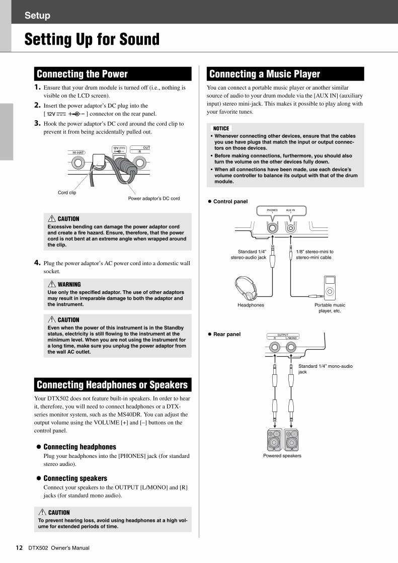
2. Insert the power adaptor’s DC plug into the [ ] connector on the rear panel.
3. Hook the power adaptor’s DC cord around the cord clip to prevent it from being accidentally pulled out.
4. Plug the power adaptor’s AC power cord into a domestic wall socket.
Your DTX502 does not feature built-in speakers. In order to hear it, therefore, you will need to connect headphones or a DTX-series monitor system, such as the MS40DR. You can adjust the output volume using the VOLUME [+] and [–] buttons on the control panel.
Connecting headphonesPlug your headphones into the [PHONES] jack (for standard stereo audio).
Connecting speakersConnect your speakers to the OUTPUT [L/MONO] and [R] jacks (for standard mono audio).
You can connect a portable music player or another similar source of audio to your drum module via the [AUX IN] (auxiliary input) stereo mini-jack. This makes it possible to play along with your favorite tunes.
Connecting the Power
CAUTIONExcessive bending can damage the power adaptor cord
and create a fire hazard. Ensure, therefore, that the power
cord is not bent at an extreme angle when wrapped around
the clip.
WARNINGUse only the specified adaptor. The use of other adaptors
may result in irreparable damage to both the adaptor and
the instrument.
CAUTIONEven when the power of this instrument is in the Standby
status, electricity is still flowing to the instrument at the
minimum level. When you are not using the instrument for
a long time, make sure you unplug the power adaptor from
the wall AC outlet.
Connecting Headphones or Speakers
CAUTIONTo prevent hearing loss, avoid using headphones at a high vol-
ume for extended periods of time.
Cord clipPower adaptor’s DC cord
Connecting a Music Player
• Whenever connecting other devices, ensure that the cables
you use have plugs that match the input or output connec-
tors on those devices.
• Before making connections, furthermore, you should also
turn the volume on the other devices fully down.
• When all connections have been made, use each device’s
volume controller to balance its output with that of the drum
module.
NOTICE
Control panel
Rear panel
1/8” stereo-mini to stereo-mini cable
Standard 1/4”stereo-audio jack
Standard 1/4” mono-audio jack
Portable music player, etc.
Headphones
Powered speakers
Setup
Setting Up for Sound
13
DTX502 Owner’s Manual1. If you have connected your drum module to other audio devices such as powered speakers, ensure that the volume on those devices is turned down fully.
2. Press the [ ] (Standby/On) button.
When you turn on your DTX502 for the first time, the Initial Setup page will be displayed. On this page, you will be required to specify the following.
1. Identify your drum kit using the Data Dial and press the [SAVE/ENTER] button.
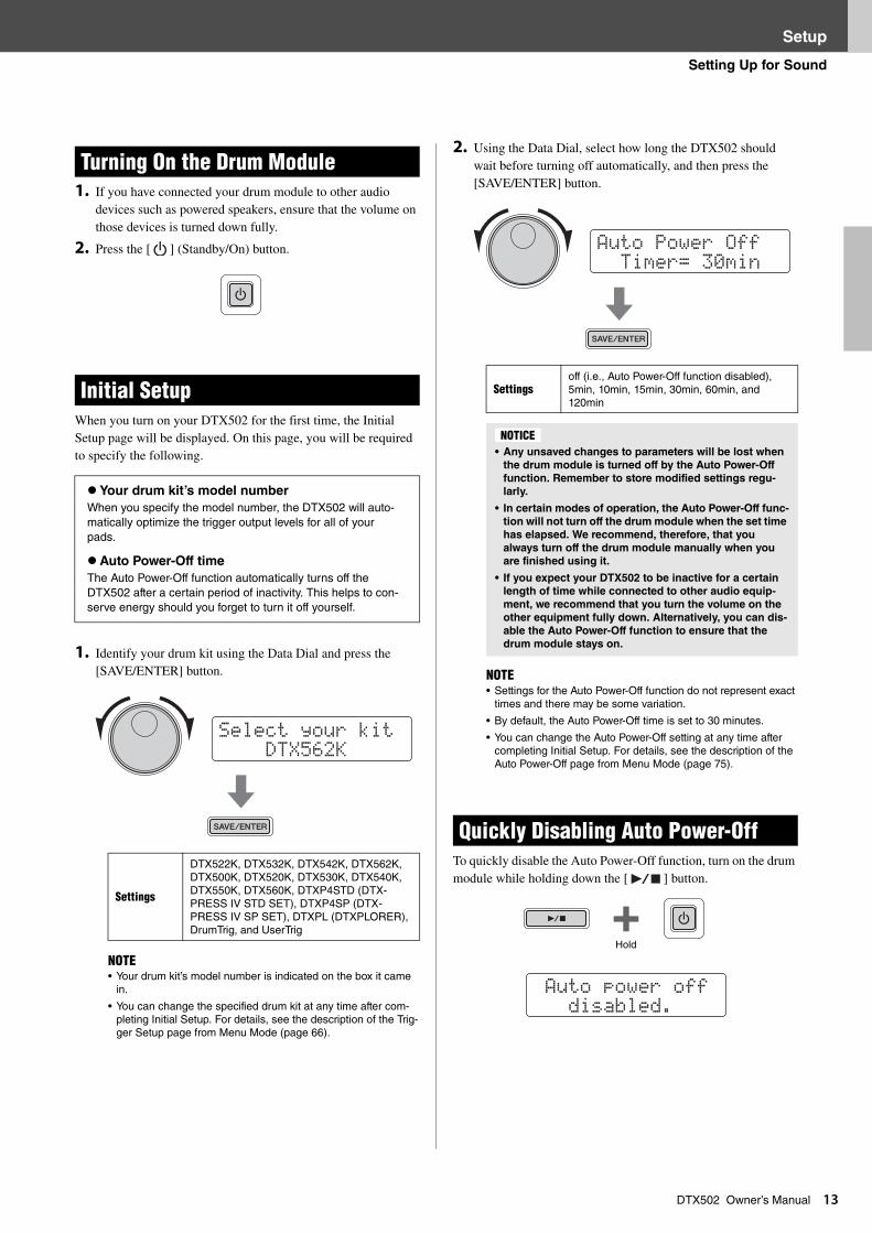
2. Using the Data Dial, select how long the DTX502 should wait before turning off automatically, and then press the [SAVE/ENTER] button.
To quickly disable the Auto Power-Off function, turn on the drum module while holding down the [ ] button.
Turning On the Drum Module
Initial Setup
Your drum kit’s model number
When you specify the model number, the DTX502 will auto-matically optimize the trigger output levels for all of your pads.
Auto Power-Off time
The Auto Power-Off function automatically turns off the DTX502 after a certain period of inactivity. This helps to con-serve energy should you forget to turn it off yourself.
Settings
DTX522K, DTX532K, DTX542K, DTX562K, DTX500K, DTX520K, DTX530K, DTX540K, DTX550K, DTX560K, DTXP4STD (DTX-PRESS IV STD SET), DTXP4SP (DTX-PRESS IV SP SET), DTXPL (DTXPLORER), DrumTrig, and UserTrig
NOTE• Your drum kit’s model number is indicated on the box it came
in.
• You can change the specified drum kit at any time after com-pleting Initial Setup. For details, see the description of the Trig-ger Setup page from Menu Mode (page 66).
Select your kit DtX562K
Settingsoff (i.e., Auto Power-Off function disabled), 5min, 10min, 15min, 30min, 60min, and 120min
• Any unsaved changes to parameters will be lost when
the drum module is turned off by the Auto Power-Off
function. Remember to store modified settings regu-
larly.
• In certain modes of operation, the Auto Power-Off func-
tion will not turn off the drum module when the set time
has elapsed. We recommend, therefore, that you
always turn off the drum module manually when you
are finished using it.
• If you expect your DTX502 to be inactive for a certain
length of time while connected to other audio equip-
ment, we recommend that you turn the volume on the
other equipment fully down. Alternatively, you can dis-
able the Auto Power-Off function to ensure that the
drum module stays on.
NOTE• Settings for the Auto Power-Off function do not represent exact
times and there may be some variation.
• By default, the Auto Power-Off time is set to 30 minutes.
• You can change the Auto Power-Off setting at any time after completing Initial Setup. For details, see the description of the Auto Power-Off page from Menu Mode (page 75).
Quickly Disabling Auto Power-Off
Auto Power Off timer= 30min
NOTICE
Auto power off disabled.
Hold
Setup
Setting Up for Sound
14
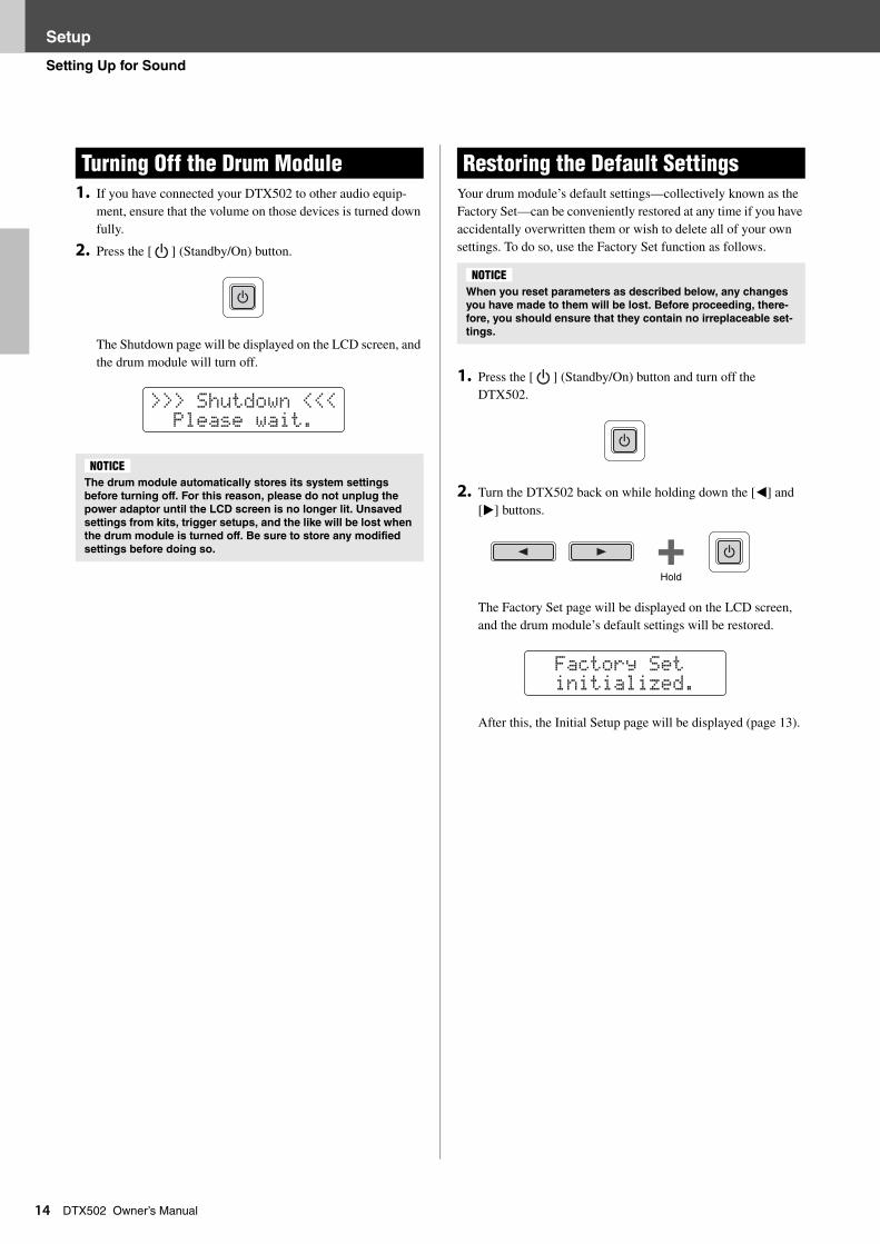
DTX502 Owner’s Manual1. If you have connected your DTX502 to other audio equip-ment, ensure that the volume on those devices is turned down fully.
2. Press the [ ] (Standby/On) button.
The Shutdown page will be displayed on the LCD screen, and the drum module will turn off.
Your drum module’s default settings—collectively known as the Factory Set—can be conveniently restored at any time if you have accidentally overwritten them or wish to delete all of your own settings. To do so, use the Factory Set function as follows.
1. Press the [ ] (Standby/On) button and turn off the DTX502.
2. Turn the DTX502 back on while holding down the [<] and [>] buttons.
The Factory Set page will be displayed on the LCD screen, and the drum module’s default settings will be restored.
After this, the Initial Setup page will be displayed (page 13).
Turning Off the Drum Module
The drum module automatically stores its system settings
before turning off. For this reason, please do not unplug the
power adaptor until the LCD screen is no longer lit. Unsaved
settings from kits, trigger setups, and the like will be lost when
the drum module is turned off. Be sure to store any modified
settings before doing so.
>>> Shutdown <<< Please wait.
NOTICE
Restoring the Default Settings
When you reset parameters as described below, any changes
you have made to them will be lost. Before proceeding, there-
fore, you should ensure that they contain no irreplaceable set-
tings.
NOTICE
Hold
Factory Set initialized.
Basic Techniques
Basic Techniques
Basic DTX502 Operations
15
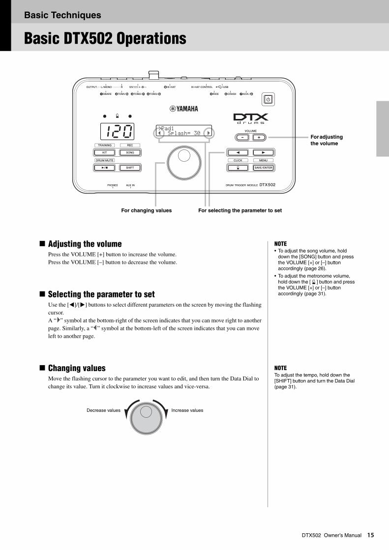
DTX502 Owner’s ManualAdjusting the volumePress the VOLUME [+] button to increase the volume. Press the VOLUME [–] button to decrease the volume.
Selecting the parameter to setUse the [<]/[>] buttons to select different parameters on the screen by moving the flashing cursor.A “‚” symbol at the bottom-right of the screen indicates that you can move right to another page. Similarly, a “”” symbol at the bottom-left of the screen indicates that you can move left to another page.
Changing valuesMove the flashing cursor to the parameter you want to edit, and then turn the Data Dial to change its value. Turn it clockwise to increase values and vice-versa.
>Pad1” Splash= 30 ‚120 For adjusting
the volume
For changing values For selecting the parameter to set
NOTE• To adjust the song volume, hold
down the [SONG] button and press the VOLUME [+] or [–] button accordingly (page 26).
• To adjust the metronome volume, hold down the [ ] button and press the VOLUME [+] or [–] button accordingly (page 31).
NOTETo adjust the tempo, hold down the [SHIFT] button and turn the Data Dial (page 31).
Increase valuesDecrease values
Basic Techniques
1
Striking the Drum Pads
6
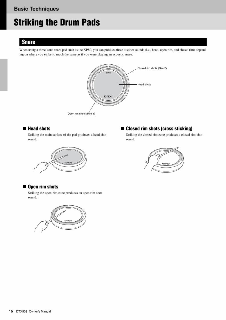
DTX502 Owner’s ManualWhen using a three-zone snare pad such as the XP80, you can produce three distinct sounds (i.e., head, open rim, and closed rim) depend-ing on where you strike it, much the same as if you were playing an acoustic snare.
Head shotsStriking the main surface of the pad produces a head shot sound.
Open rim shotsStriking the open-rim zone produces an open rim-shot sound.
Closed rim shots (cross sticking)Striking the closed-rim zone produces a closed rim-shot sound.
Snare
Closed rim shots (Rim 2)
Head shots
Open rim shots (Rim 1)
Basic Techniques
Striking the Drum Pads
17
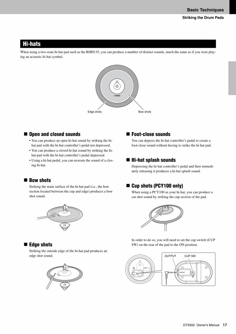
DTX502 Owner’s ManualWhen using a two-zone hi-hat pad such as the RHH135, you can produce a number of distinct sounds, much the same as if you were play-ing an acoustic hi-hat cymbal.
Open and closed sounds• You can produce an open hi-hat sound by striking the hi-
hat pad with the hi-hat controller’s pedal not depressed.
• You can produce a closed hi-hat sound by striking the hi-hat pad with the hi-hat controller’s pedal depressed.
• Using a hi-hat pedal, you can recreate the sound of a clos-ing hi-hat.
Bow shotsStriking the main surface of the hi-hat pad (i.e., the bow section located between the cup and edge) produces a bow shot sound.
Edge shotsStriking the outside edge of the hi-hat pad produces an edge shot sound.
Foot-close soundsYou can depress the hi-hat controller’s pedal to create a foot-close sound without having to strike the hi-hat pad.
Hi-hat splash soundsDepressing the hi-hat controller’s pedal and then immedi-ately releasing it produces a hi-hat splash sound.
Cup shots (PCY100 only)When using a PCY100 as your hi-hat, you can produce a cut shot sound by striking the cup section of the pad.
In order to do so, you will need to set the cup switch (CUP SW) on the rear of the pad to the ON position.
Hi-hats
Edge shots Bow shots
OUTPUT CUP SW
Basic Techniques
Striking the Drum Pads
18
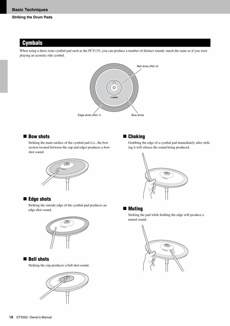
DTX502 Owner’s ManualWhen using a three-zone cymbal pad such as the PCY135, you can produce a number of distinct sounds, much the same as if you were playing an acoustic ride cymbal.
Bow shotsStriking the main surface of the cymbal pad (i.e., the bow section located between the cup and edge) produces a bow shot sound.
Edge shotsStriking the outside edge of the cymbal pad produces an edge shot sound.
Bell shotsStriking the cup produces a bell shot sound.
ChokingGrabbing the edge of a cymbal pad immediately after strik-ing it will silence the sound being produced.
MutingStriking the pad while holding the edge will produce a muted sound.
Cymbals
Edge shots (Rim 1)
Bell shots (Rim 2)
Bow shots
Basic Techniques
Selecting & Playing a Kit
19
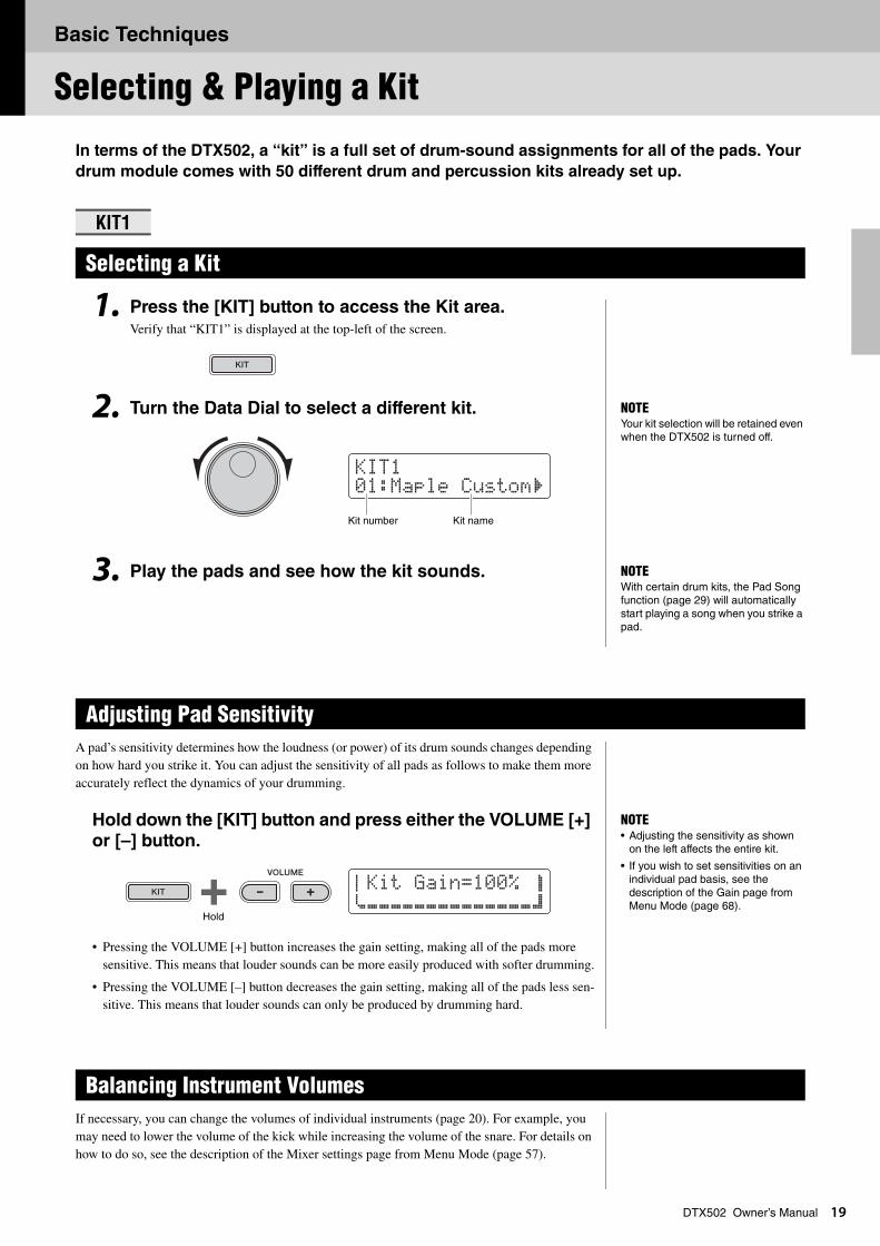
DTX502 Owner’s ManualIn terms of the DTX502, a “kit” is a full set of drum-sound assignments for all of the pads. Your
drum module comes with 50 different drum and percussion kits already set up.
1. Press the [KIT] button to access the Kit area.Verify that “KIT1” is displayed at the top-left of the screen.
2. Turn the Data Dial to select a different kit.
3. Play the pads and see how the kit sounds.
A pad’s sensitivity determines how the loudness (or power) of its drum sounds changes depending on how hard you strike it. You can adjust the sensitivity of all pads as follows to make them more accurately reflect the dynamics of your drumming.
Hold down the [KIT] button and press either the VOLUME [+]
or [–] button.
• Pressing the VOLUME [+] button increases the gain setting, making all of the pads more sensitive. This means that louder sounds can be more easily produced with softer drumming.
• Pressing the VOLUME [–] button decreases the gain setting, making all of the pads less sen-sitive. This means that louder sounds can only be produced by drumming hard.
If necessary, you can change the volumes of individual instruments (page 20). For example, you may need to lower the volume of the kick while increasing the volume of the snare. For details on how to do so, see the description of the Mixer settings page from Menu Mode (page 57).
KIT1
Selecting a Kit
Adjusting Pad Sensitivity
Balancing Instrument Volumes
NOTEYour kit selection will be retained even when the DTX502 is turned off.
KIt101:Maple Custom‚
Kit number Kit name
NOTEWith certain drum kits, the Pad Song function (page 29) will automatically start playing a song when you strike a pad.
NOTE• Adjusting the sensitivity as shown
on the left affects the entire kit.
• If you wish to set sensitivities on an individual pad basis, see the description of the Gain page from Menu Mode (page 68).
aKit Gain=100% bcÇÇÇÇÇÇÇÇÇÇÇÇÇÇd
Hold
Basic Techniques
2
Building Your Own Unique Kits
0
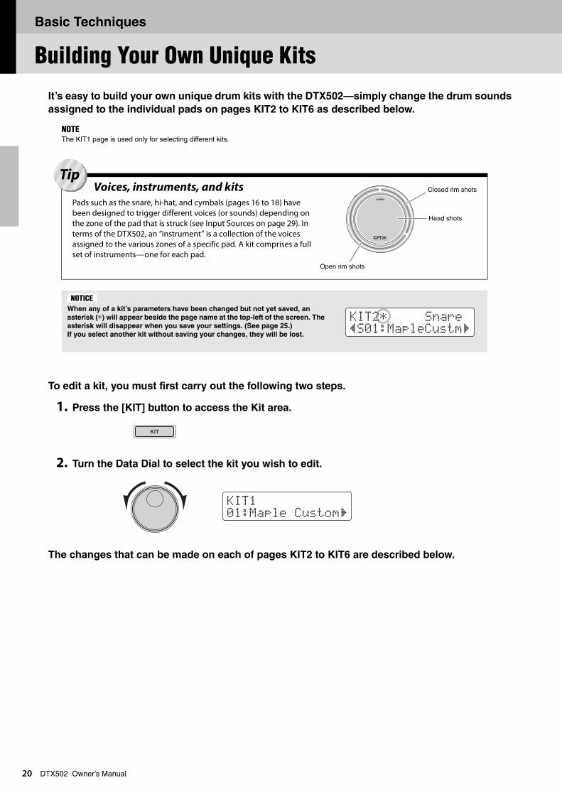
DTX502 Owner’s ManualIt’s easy to build your own unique drum kits with the DTX502—simply change the drum sounds
assigned to the individual pads on pages KIT2 to KIT6 as described below.
To edit a kit, you must first carry out the following two steps.
1. Press the [KIT] button to access the Kit area.
2. Turn the Data Dial to select the kit you wish to edit.
The changes that can be made on each of pages KIT2 to KIT6 are described below.
NOTEThe KIT1 page is used only for selecting different kits.
When any of a kit’s parameters have been changed but not yet saved, an
asterisk (*) will appear beside the page name at the top-left of the screen. The
asterisk will disappear when you save your settings. (See page 25.)
If you select another kit without saving your changes, they will be lost.
Voices, instruments, and kitsPads such as the snare, hi-hat, and cymbals (pages 16 to 18) have been designed to trigger different voices (or sounds) depending on the zone of the pad that is struck (see Input Sources on page 29). In terms of the DTX502, an “instrument” is a collection of the voices assigned to the various zones of a specific pad. A kit comprises a full set of instruments—one for each pad.
Closed rim shots
Head shots
Open rim shots
Tip
NOTICE
KIt2* Snare”S01:MapleCustm‚
KIt101:Maple Custom‚
Basic Techniques
Building Your Own Unique Kits
21
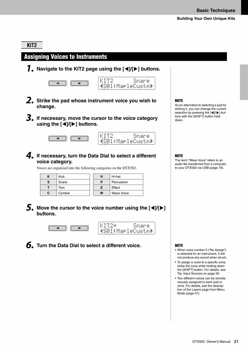
DTX502 Owner’s Manual1. Navigate to the KIT2 page using the [<]/[>] buttons.
2. Strike the pad whose instrument voice you wish to change.
3. If necessary, move the cursor to the voice category using the [<]/[>] buttons.
4. If necessary, turn the Data Dial to select a different voice category.
Voices are organized into the following categories on the DTX502.
5. Move the cursor to the voice number using the [<]/[>] buttons.
6. Turn the Data Dial to select a different voice.
KIT2
Assigning Voices to Instruments
K Kick H Hi-hat
S Snare P Percussion
T Tom E Effect
C Cymbal W Wave Voice
KIt2 Snare”S01:MapleCustm‚
NOTEAs an alternative to selecting a pad by striking it, you can change the current selection by pressing the [<]/[>] but-tons with the [SHIFT] button held down.
KIt2 Snare”S01:MapleCustm‚
NOTEThe term “Wave Voice” refers to an audio file transferred from a computer to your DTX502 via USB (page 79).
KIt2* Snare”S01:MapleCustm‚
NOTE• When voice number 0 (“No Assign”)
is selected for an instrument, it will not produce any sound when struck.
• To assign a voice to a specific zone, strike the zone while holding down the [SHIFT] button. For details, see Tip: Input Sources on page 29.
• Two different voices can be simulta-neously assigned to each pad or zone. For details, see the descrip-tion of the Layers page from Menu Mode (page 57).
Basic Techniques
Building Your Own Unique Kits
22
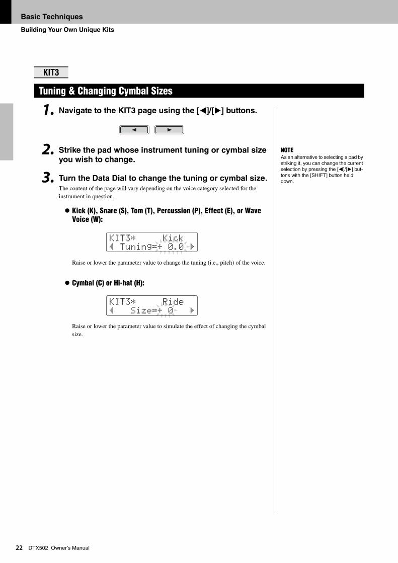
DTX502 Owner’s Manual1. Navigate to the KIT3 page using the [<]/[>] buttons.
2. Strike the pad whose instrument tuning or cymbal size
you wish to change.
3. Turn the Data Dial to change the tuning or cymbal size.
The content of the page will vary depending on the voice category selected for the instrument in question.
Kick (K), Snare (S), Tom (T), Percussion (P), Effect (E), or Wave Voice (W):
Raise or lower the parameter value to change the tuning (i.e., pitch) of the voice.
Cymbal (C) or Hi-hat (H):
Raise or lower the parameter value to simulate the effect of changing the cymbal size.
KIT3
Tuning & Changing Cymbal Sizes
NOTEAs an alternative to selecting a pad by striking it, you can change the current selection by pressing the [<]/[>] but-tons with the [SHIFT] button held down.
KIt3* Kick” tuning=+ 0.0 ‚
KIt3* Ride” Size=+ 0 ‚
Basic Techniques
Building Your Own Unique Kits
23
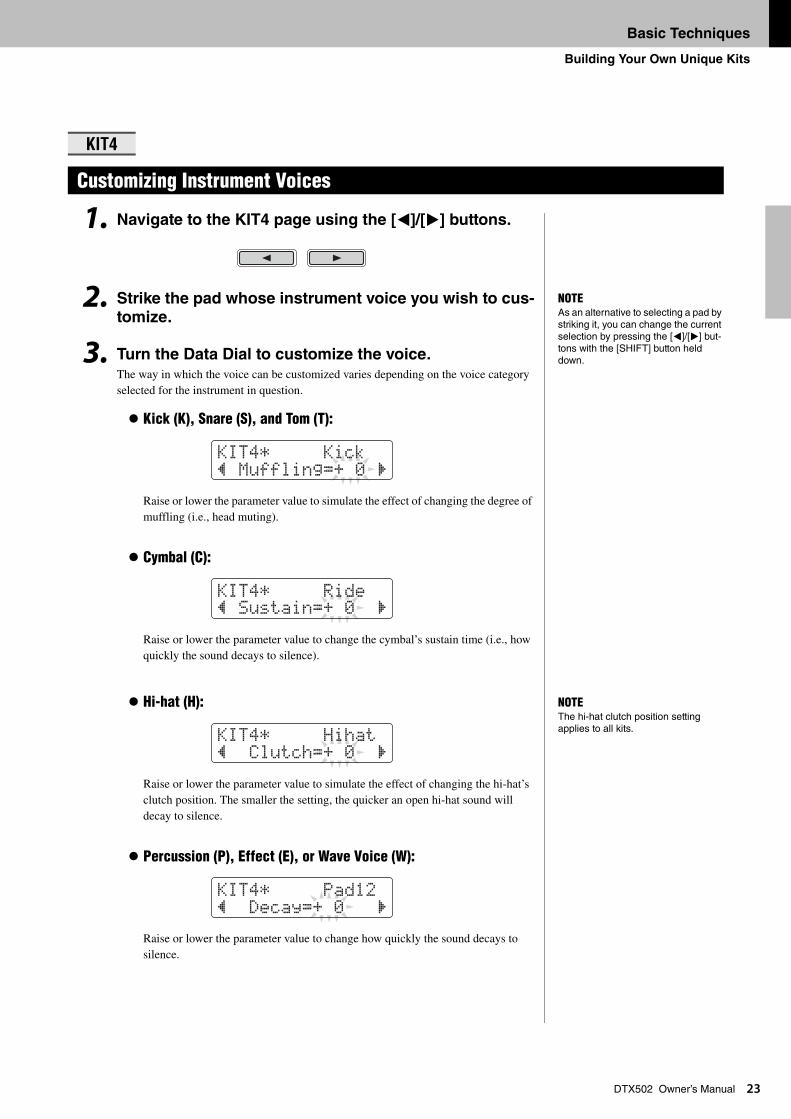
DTX502 Owner’s Manual1. Navigate to the KIT4 page using the [<]/[>] buttons.
2. Strike the pad whose instrument voice you wish to cus-
tomize.
3. Turn the Data Dial to customize the voice.
The way in which the voice can be customized varies depending on the voice category selected for the instrument in question.
Kick (K), Snare (S), and Tom (T):
Raise or lower the parameter value to simulate the effect of changing the degree of muffling (i.e., head muting).
Cymbal (C):
Raise or lower the parameter value to change the cymbal’s sustain time (i.e., how quickly the sound decays to silence).
Hi-hat (H):
Raise or lower the parameter value to simulate the effect of changing the hi-hat’s clutch position. The smaller the setting, the quicker an open hi-hat sound will decay to silence.
Percussion (P), Effect (E), or Wave Voice (W):
Raise or lower the parameter value to change how quickly the sound decays to silence.
KIT4
Customizing Instrument Voices
NOTEAs an alternative to selecting a pad by striking it, you can change the current selection by pressing the [<]/[>] but-tons with the [SHIFT] button held down.
KIt4* Kick” Muffling=+ 0 ‚
KIt4* Ride” Sustain=+ 0 ‚
NOTEThe hi-hat clutch position setting applies to all kits.
KIt4* Hihat” Clutch=+ 0 ‚
KIt4* Pad12” Decay=+ 0 ‚
Basic Techniques
Building Your Own Unique Kits
24
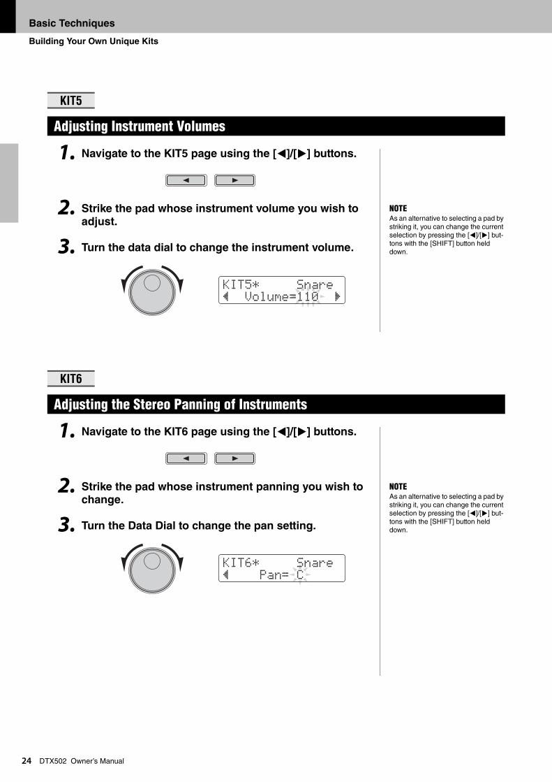
DTX502 Owner’s Manual1. Navigate to the KIT5 page using the [<]/[>] buttons.
2. Strike the pad whose instrument volume you wish to
adjust.
3. Turn the data dial to change the instrument volume.
1. Navigate to the KIT6 page using the [<]/[>] buttons.
2. Strike the pad whose instrument panning you wish to change.
3. Turn the Data Dial to change the pan setting.
KIT5
Adjusting Instrument Volumes
KIT6
Adjusting the Stereo Panning of Instruments
NOTEAs an alternative to selecting a pad by striking it, you can change the current selection by pressing the [<]/[>] but-tons with the [SHIFT] button held down.
KIt5* Snare” Volume=110 ‚
NOTEAs an alternative to selecting a pad by striking it, you can change the current selection by pressing the [<]/[>] but-tons with the [SHIFT] button held down.
KIt6* Snare” Pan= C
Basic Techniques
Saving Customized Kits
25
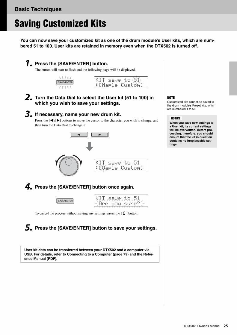
DTX502 Owner’s ManualYou can now save your customized kit as one of the drum module’s User kits, which are num-
bered 51 to 100. User kits are retained in memory even when the DTX502 is turned off.
1. Press the [SAVE/ENTER] button.The button will start to flash and the following page will be displayed.
2. Turn the Data Dial to select the User kit (51 to 100) in which you wish to save your settings.
3. If necessary, name your new drum kit.Press the [<]/[>] buttons to move the cursor to the character you wish to change, and then turn the Data Dial to change it.
4. Press the [SAVE/ENTER] button once again.
To cancel the process without saving any settings, press the [ ] button.
5. Press the [SAVE/ENTER] button to save your settings.
User kit data can be transferred between your DTX502 and a computer via
USB. For details, refer to Connecting to a Computer (page 79) and the Refer-
ence Manual (PDF).
KIt saVe to 51:[Maple Custom]
NOTECustomized kits cannot be saved to the drum module’s Preset kits, which are numbered 1 to 50.
When you save new settings to
a User kit, its current settings
will be overwritten. Before pro-
ceeding, therefore, you should
ensure that the kit in question
contains no irreplaceable set-
tings.
NOTICE
KIt saVe to 51:[Oaple Custom]
KIt saVe to 51 Are you sure?
Basic Techniques
2
Performing with a Song
6
DTX502 Owner’s ManualYour DTX502 comes complete with a full complement of practice songs. Covering a wide range
of genres, they provide a convenient, enjoyable way to practice drumming.
Songs are selected on the SONG1 page.
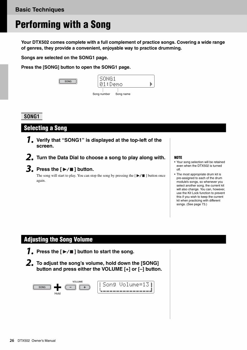
Press the [SONG] button to open the SONG1 page.
1. Verify that “SONG1” is displayed at the top-left of the screen.
2. Turn the Data Dial to choose a song to play along with.
3. Press the [ ] button.
The song will start to play. You can stop the song by pressing the [ ] button once again.
1. Press the [ ] button to start the song.
2. To adjust the song’s volume, hold down the [SONG]
button and press either the VOLUME [+] or [–] button.
SONG1
Selecting a Song
Adjusting the Song Volume
SONG101:Demo ‚
Song number Song name
NOTE• Your song selection will be retained
even when the DTX502 is turned off.
• The most appropriate drum kit is pre-assigned to each of the drum module’s songs, so whenever you select another song, the current kit will also change. You can, however, use the Kit Lock function to prevent this if you wish to keep the current kit when practicing with different songs. (See page 73.)
aSong Volume=13bcÇÇÇÇÇÇÇÇÇÇÇÇÇÇd
Hold
Basic Techniques
Performing with a Song
27
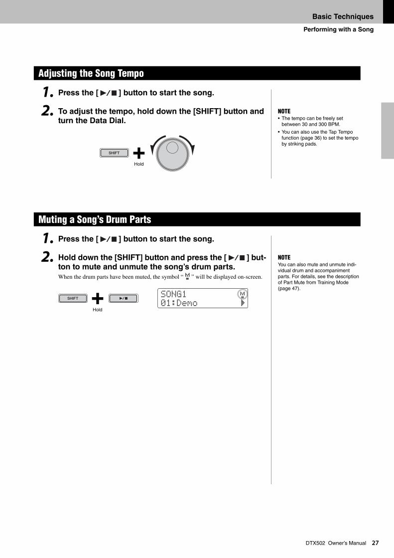
DTX502 Owner’s Manual1. Press the [ ] button to start the song.
2. To adjust the tempo, hold down the [SHIFT] button and turn the Data Dial.
1. Press the [ ] button to start the song.
2. Hold down the [SHIFT] button and press the [ ] but-ton to mute and unmute the song’s drum parts.
When the drum parts have been muted, the symbol “ M ” will be displayed on-screen.
Adjusting the Song Tempo
Muting a Song’s Drum Parts
NOTE• The tempo can be freely set
between 30 and 300 BPM.
• You can also use the Tap Tempo function (page 36) to set the tempo by striking pads.
Hold
NOTEYou can also mute and unmute indi-vidual drum and accompaniment parts. For details, see the description of Part Mute from Training Mode (page 47).
SONG1 M01:Demo ‚
Hold
Basic Techniques
Performing with a Song
28
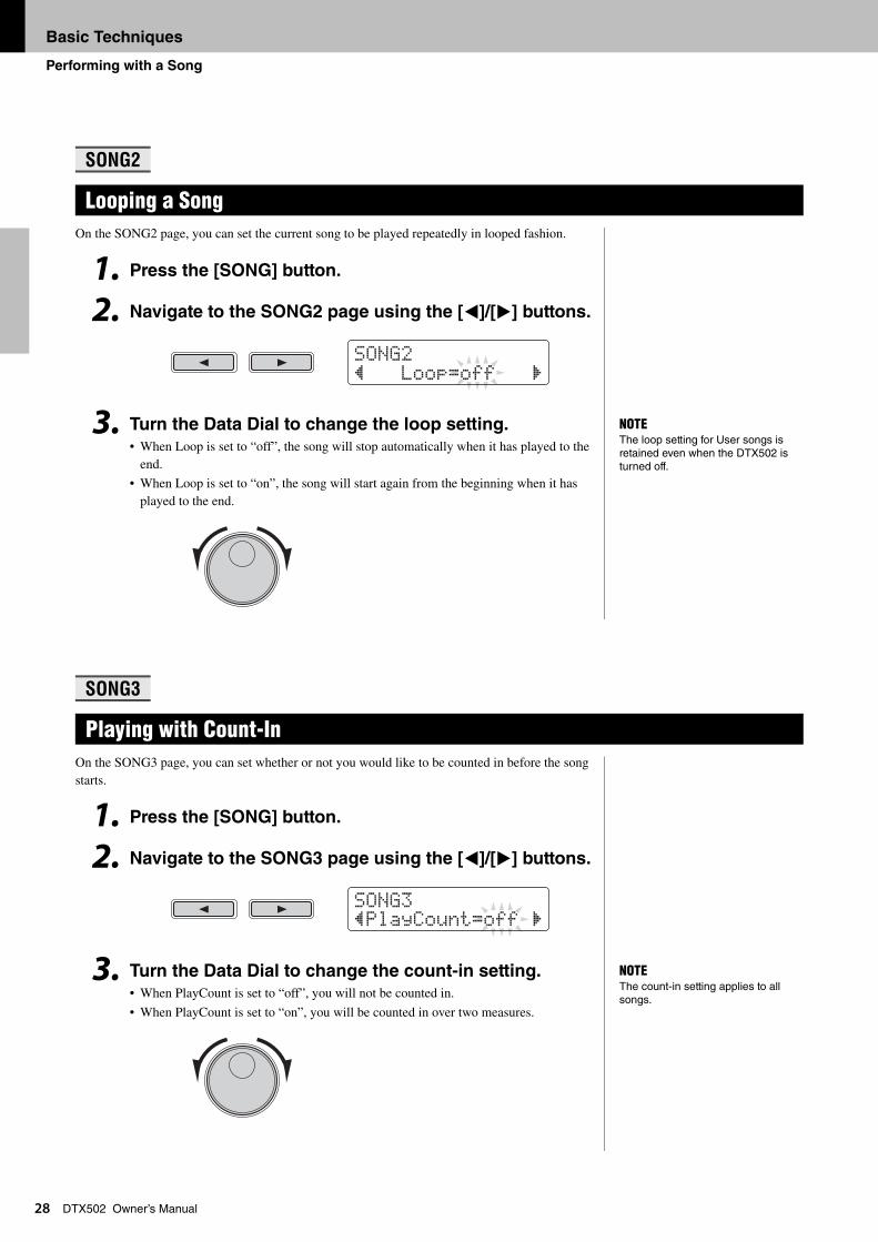
DTX502 Owner’s ManualOn the SONG2 page, you can set the current song to be played repeatedly in looped fashion.
1. Press the [SONG] button.
2. Navigate to the SONG2 page using the [<]/[>] buttons.
3. Turn the Data Dial to change the loop setting.
• When Loop is set to “off”, the song will stop automatically when it has played to the end.
• When Loop is set to “on”, the song will start again from the beginning when it has played to the end.
On the SONG3 page, you can set whether or not you would like to be counted in before the song starts.
1. Press the [SONG] button.
2. Navigate to the SONG3 page using the [<]/[>] buttons.
3. Turn the Data Dial to change the count-in setting.• When PlayCount is set to “off”, you will not be counted in.
• When PlayCount is set to “on”, you will be counted in over two measures.
SONG2
Looping a Song
SONG3
Playing with Count-In
SONG2” Loop=off ‚
NOTEThe loop setting for User songs is retained even when the DTX502 is turned off.
SONG3”PlayCount=off ‚
NOTEThe count-in setting applies to all songs.
Basic Techniques
Performing with a Song
29
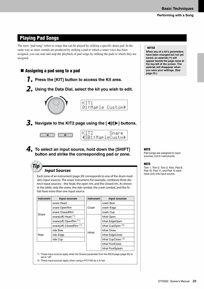
DTX502 Owner’s ManualThe term “pad song” refers to songs that can be played by striking a specific drum pad. In the same way as snare sounds are produced by striking a pad to which a snare voice has been assigned, you can start and stop the playback of pad songs by striking the pads to which they are assigned.
Assigning a pad song to a pad
1. Press the [KIT] button to access the Kit area.
2. Using the Data Dial, select the kit you wish to edit.
3. Navigate to the KIT2 page using the [<]/[>] buttons.
4. To select an input source, hold down the [SHIFT] button and strike the corresponding pad or zone.
Playing Pad Songs
When any of a kit’s parameters
have been changed but not yet
saved, an asterisk (*) will
appear beside the page name at
the top-left of the screen. The
asterisk will disappear when
you save your settings. (See
page 25.)
NOTICE
KIt101:Maple Custom‚
KIt2 Snare”S01:MapleCustm‚
NOTEPad songs are assigned to input sources, not to instruments.
NOTETom 1, Tom 2, Tom 3, Kick, Pad 8, Pad 10, Pad 11, and Pad 12 each have only one input source.
Input SourcesEach zone of an instrument (page 20) corresponds to one of the drum mod-ule’s input sources. The snare instrument, for example, combines three dis-tinct input sources—the head, the open rim, and the closed rim. As shown in the table, only the snare, the ride cymbal, the crash cymbal, and the hi-hat have more than one input source.
*1: These input sources apply when the Snares parameter from the KitC6 page (page 62) is set to “off”.
*2: These input sources apply when using a PCY100 as a hi-hat.
Instrument Input sources
Snare
snare Head
snare OpenRim
snare ClosedRim
snare(off) Head (*1)
snare(off) OpenRim (*1)
snare(off) ClosedRim (*1)
Ride
ride Bow
ride Edge
ride Cup
Crash
crash Bow
crash Edge
crash Cup
HiHat
hihat Open
hihat EdgeOpen
hihat CupOpen (*2)
hihat Close
hihat EdgeClose
hihat CupClose (*2)
hihat FootClose
hihat FootSplash
Instrument Input sources
Tip
Basic Techniques
Performing with a Song
30
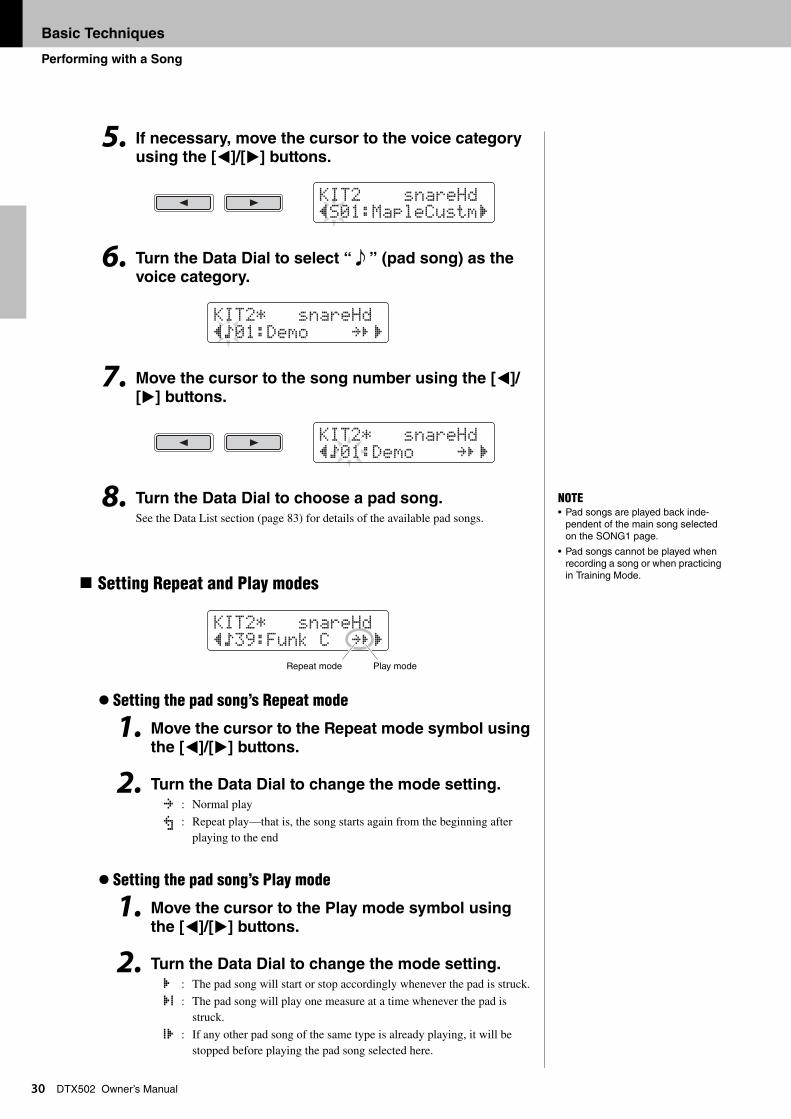
DTX502 Owner’s Manual5. If necessary, move the cursor to the voice category using the [<]/[>] buttons.
6. Turn the Data Dial to select “ e ” (pad song) as the voice category.
7. Move the cursor to the song number using the [<]/
[>] buttons.
8. Turn the Data Dial to choose a pad song.
See the Data List section (page 83) for details of the available pad songs.
Setting Repeat and Play modes
Setting the pad song’s Repeat mode
1. Move the cursor to the Repeat mode symbol using the [<]/[>] buttons.
2. Turn the Data Dial to change the mode setting. : Normal play
: Repeat play—that is, the song starts again from the beginning after playing to the end
Setting the pad song’s Play mode
1. Move the cursor to the Play mode symbol using
the [<]/[>] buttons.
2. Turn the Data Dial to change the mode setting.
: The pad song will start or stop accordingly whenever the pad is struck.
: The pad song will play one measure at a time whenever the pad is struck.
: If any other pad song of the same type is already playing, it will be stopped before playing the pad song selected here.
KIt2 snareHd”S01:MapleCustm‚
KIt2* snareHd”Ö01:Demo ≥‚
KIt2* snareHd”Ö01:Demo ≥‚
NOTE• Pad songs are played back inde-
pendent of the main song selected on the SONG1 page.
• Pad songs cannot be played when recording a song or when practicing in Training Mode.
KIt2* snareHd”Ö39:Funk C ≥‚
Repeat mode Play mode
≥μ
ÂÊ
Á
Basic Techniques
Using the Metronome
31
DTX502 Owner’s ManualPlaying your electronic drum kit along with the built-in metronome is a great way to perfect
your rhythm.
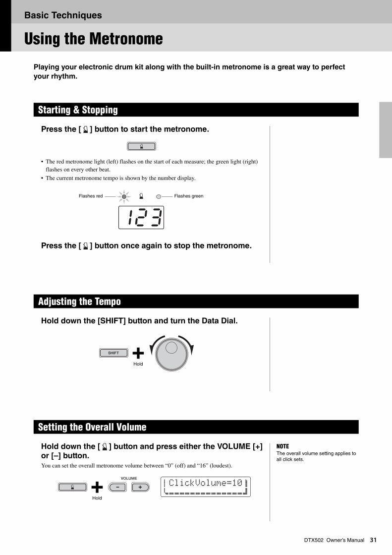
Press the [ ] button to start the metronome.
• The red metronome light (left) flashes on the start of each measure; the green light (right) flashes on every other beat.
• The current metronome tempo is shown by the number display.
Press the [ ] button once again to stop the metronome.
Hold down the [SHIFT] button and turn the Data Dial.
Hold down the [ ] button and press either the VOLUME [+] or [–] button.You can set the overall metronome volume between “0” (off) and “16” (loudest).
Starting & Stopping
Adjusting the Tempo
Setting the Overall Volume
Flashes greenFlashes red
Hold
NOTEThe overall volume setting applies to all click sets.
aClickVolume=10bcÇÇÇÇÇÇÇÇÇÇÇÇÇÇd
Hold
Basic Techniques
3
Customizing the Metronome
2
DTX502 Owner’s ManualThis section describes how to make advanced metronome settings. A total of six pages (CLK1
to CLK6) are used for this purpose.
The individual parameters that can be changed on pages CLK1 to CLK6 will now be described.
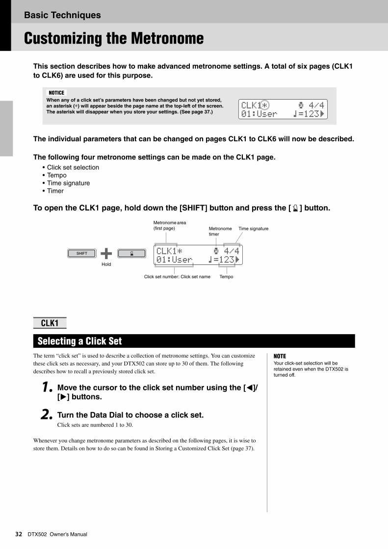
The following four metronome settings can be made on the CLK1 page.
• Click set selection• Tempo• Time signature• Timer
To open the CLK1 page, hold down the [SHIFT] button and press the [ ] button.
The term “click set” is used to describe a collection of metronome settings. You can customize these click sets as necessary, and your DTX502 can store up to 30 of them. The following describes how to recall a previously stored click set.
1. Move the cursor to the click set number using the [<]/[>] buttons.
2. Turn the Data Dial to choose a click set.Click sets are numbered 1 to 30.
Whenever you change metronome parameters as described on the following pages, it is wise to store them. Details on how to do so can be found in Storing a Customized Click Set (page 37).
When any of a click set’s parameters have been changed but not yet stored,
an asterisk (*) will appear beside the page name at the top-left of the screen.
The asterisk will disappear when you store your settings. (See page 37.)
CLK1
Selecting a Click Set
NOTICE
CLK1* ∫ 4/401:User ⁄=123‚
CLK1* ∫ 4/401:User ⁄=123‚
Hold
Metronome area (first page)
Click set number: Click set name
Metronome timer
Time signature
Tempo
NOTEYour click-set selection will be retained even when the DTX502 is turned off.
Basic Techniques
Customizing the Metronome
33
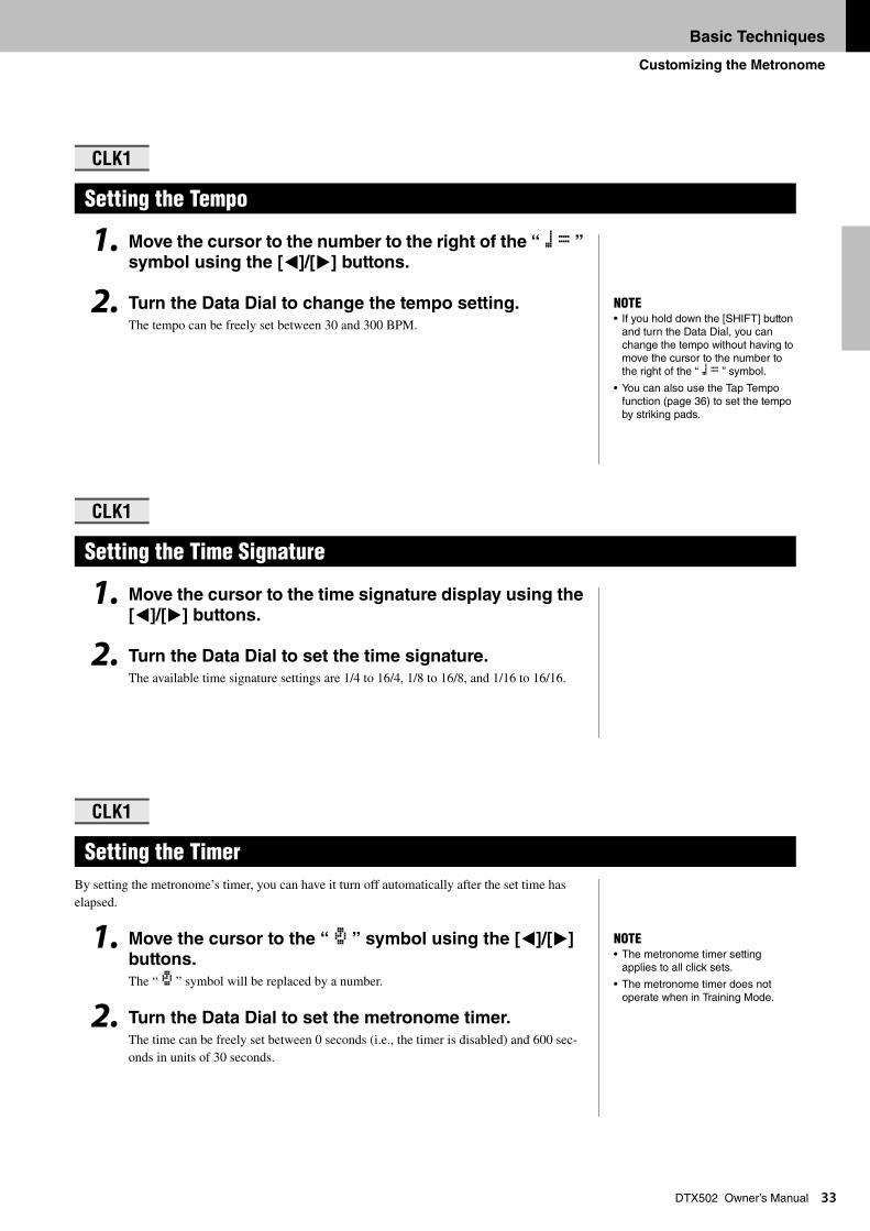
DTX502 Owner’s Manual1. Move the cursor to the number to the right of the “ ⁄= ” symbol using the [<]/[>] buttons.
2. Turn the Data Dial to change the tempo setting. The tempo can be freely set between 30 and 300 BPM.
1. Move the cursor to the time signature display using the [<]/[>] buttons.
2. Turn the Data Dial to set the time signature. The available time signature settings are 1/4 to 16/4, 1/8 to 16/8, and 1/16 to 16/16.
By setting the metronome’s timer, you can have it turn off automatically after the set time has elapsed.
1. Move the cursor to the “ ∫ ” symbol using the [<]/[>] buttons.
The “ ∫ ” symbol will be replaced by a number.
2. Turn the Data Dial to set the metronome timer. The time can be freely set between 0 seconds (i.e., the timer is disabled) and 600 sec-onds in units of 30 seconds.
CLK1
Setting the Tempo
CLK1
Setting the Time Signature
CLK1
Setting the Timer
NOTE• If you hold down the [SHIFT] button
and turn the Data Dial, you can change the tempo without having to move the cursor to the number to the right of the “ ⁄= ” symbol.
• You can also use the Tap Tempo function (page 36) to set the tempo by striking pads.
NOTE• The metronome timer setting
applies to all click sets.
• The metronome timer does not operate when in Training Mode.
Basic Techniques
Customizing the Metronome
34
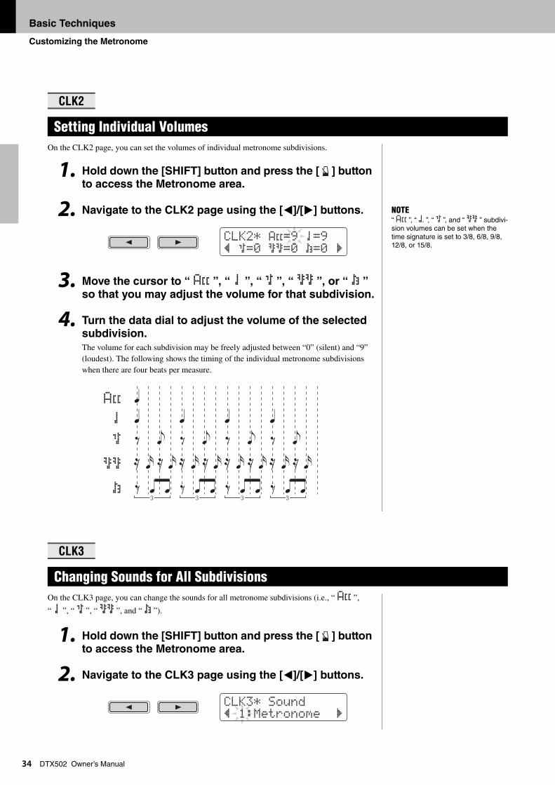
DTX502 Owner’s ManualOn the CLK2 page, you can set the volumes of individual metronome subdivisions.
1. Hold down the [SHIFT] button and press the [ ] button to access the Metronome area.
2. Navigate to the CLK2 page using the [<]/[>] buttons.
3. Move the cursor to “ A˘ ”, “ ¤ ”, “ ‹ ”, “ ßß ”, or “ Œ ” so that you may adjust the volume for that subdivision.
4. Turn the data dial to adjust the volume of the selected subdivision.The volume for each subdivision may be freely adjusted between “0” (silent) and “9” (loudest). The following shows the timing of the individual metronome subdivisions when there are four beats per measure.
On the CLK3 page, you can change the sounds for all metronome subdivisions (i.e., “ A˘ ”,
“ ¤ ”, “ ‹ ”, “ ßß ”, and “ Œ ”).
1. Hold down the [SHIFT] button and press the [ ] button to access the Metronome area.
2. Navigate to the CLK3 page using the [<]/[>] buttons.
CLK2
Setting Individual Volumes
CLK3
Changing Sounds for All Subdivisions
NOTE“ A˘ ”, “ á ”, “ ‹ ”, and “ ßß ” subdivi-sion volumes can be set when the time signature is set to 3/8, 6/8, 9/8, 12/8, or 15/8.
CLK2* A˘=9 ¤=9” ‹=0 ßß=0 Œ=0 ‚
A˘
¤
‹
ßß
Œ
CLK3* Sound” 1:Metronome ‚
Basic Techniques
Customizing the Metronome
35
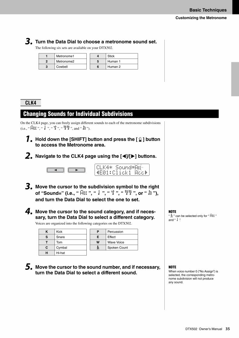
DTX502 Owner’s Manual3. Turn the Data Dial to choose a metronome sound set.The following six sets are available on your DTX502.
On the CLK4 page, you can freely assign different sounds to each of the metronome subdivisions
(i.e., “ A˘ ”, “ ¤ ”, “ ‹ ”, “ ßß ”, and “ Œ ”).
1. Hold down the [SHIFT] button and press the [ ] button to access the Metronome area.
2. Navigate to the CLK4 page using the [<]/[>] buttons.
3. Move the cursor to the subdivision symbol to the right
of “Sound=” (i.e., “ A˘ ”, “ ¤ ”, “ ‹ ”, “ ßß ”, or “ Œ ”),
and turn the Data Dial to select the one to set.
4. Move the cursor to the sound category, and if neces-sary, turn the Data Dial to select a different category.
Voices are organized into the following categories on the DTX502.
5. Move the cursor to the sound number, and if necessary, turn the Data Dial to select a different sound.
1 Metronome1 4 Stick
2 Metronome2 5 Human 1
3 Cowbell 6 Human 2
CLK4
Changing Sounds for Individual Subdivisions
K Kick P Percussion
S Snare E Effect
T Tom W Wave Voice
C Cymbal ë Spoken Count
H Hi-hat
CLK4* Sound=A˘”E01:Click1 Acc‚
NOTE“ ë ” can be selected only for “ A˘ ” and “ ¤ ”.
NOTEWhen voice number 0 (“No Assign”) is selected, the corresponding metro-nome subdivision will not produce any sound.
Basic Techniques
Customizing the Metronome
36
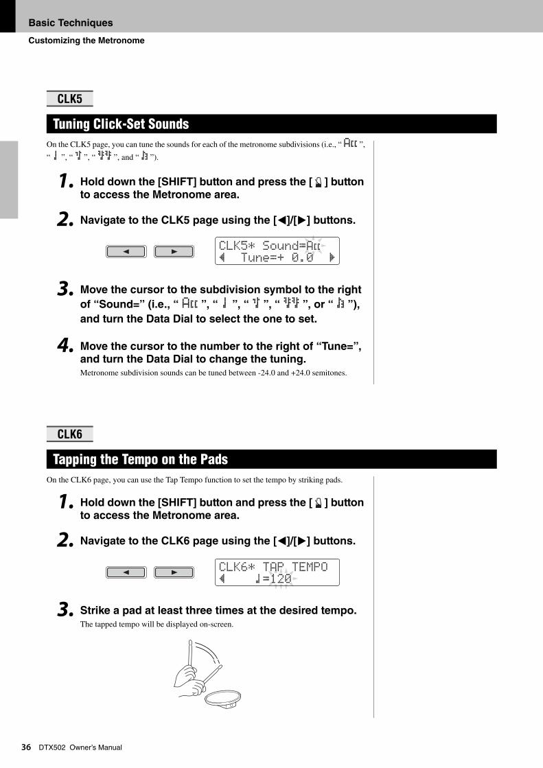
DTX502 Owner’s ManualOn the CLK5 page, you can tune the sounds for each of the metronome subdivisions (i.e., “ A˘ ”,
“ ¤ ”, “ ‹ ”, “ ßß ”, and “ Œ ”).
1. Hold down the [SHIFT] button and press the [ ] button
to access the Metronome area.
2. Navigate to the CLK5 page using the [<]/[>] buttons.
3. Move the cursor to the subdivision symbol to the right
of “Sound=” (i.e., “ A˘ ”, “ ¤ ”, “ ‹ ”, “ ßß ”, or “ Œ ”),
and turn the Data Dial to select the one to set.
4. Move the cursor to the number to the right of “Tune=”, and turn the Data Dial to change the tuning.Metronome subdivision sounds can be tuned between -24.0 and +24.0 semitones.
On the CLK6 page, you can use the Tap Tempo function to set the tempo by striking pads.
1. Hold down the [SHIFT] button and press the [ ] button
to access the Metronome area.
2. Navigate to the CLK6 page using the [<]/[>] buttons.
3. Strike a pad at least three times at the desired tempo.The tapped tempo will be displayed on-screen.
CLK5
Tuning Click-Set Sounds
CLK6
Tapping the Tempo on the Pads
CLK5* Sound=A˘” tune=+ 0.0 ‚
CLK6* tAP tEMPO” ⁄=120
Basic Techniques
Storing a Customized Click Set
37
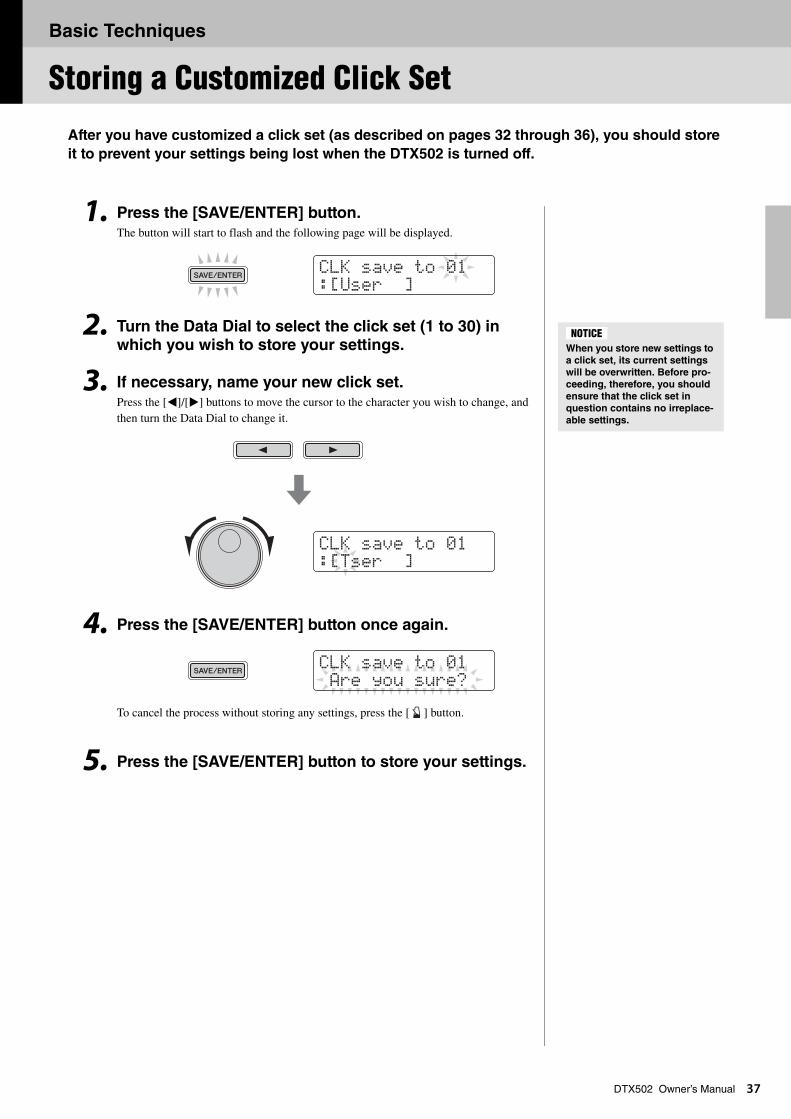
DTX502 Owner’s ManualAfter you have customized a click set (as described on pages 32 through 36), you should store
it to prevent your settings being lost when the DTX502 is turned off.
1. Press the [SAVE/ENTER] button.The button will start to flash and the following page will be displayed.
2. Turn the Data Dial to select the click set (1 to 30) in which you wish to store your settings.
3. If necessary, name your new click set. Press the [<]/[>] buttons to move the cursor to the character you wish to change, and then turn the Data Dial to change it.
4. Press the [SAVE/ENTER] button once again.
To cancel the process without storing any settings, press the [ ] button.
5. Press the [SAVE/ENTER] button to store your settings.
CLK saVe to 01:[User ]
When you store new settings to
a click set, its current settings
will be overwritten. Before pro-
ceeding, therefore, you should
ensure that the click set in
question contains no irreplace-
able settings.
NOTICE
CLK saVe to 01:[tser ]
CLK saVe to 01 Are you sure?
Basic Techniques
3
Practicing in Training Mode
8
DTX502 Owner’s ManualYour DTX502 comes complete with eight different types of training that allow you to improve
various drumming skills while having fun at the same time. You can work on your sense of
rhythm, learn drum patterns from a wide range of different musical genres, and even practice
playing as wildly as you can.
As an aid to improving your timing, Groove Check displays on-screen how early or late you are drumming. Two different training styles are available—the first uses the metronome; the second lets you play along with a song. When you have finished training, your score will be displayed on-screen.
Training procedure
1. Hold down the [SHIFT] button and press the [KIT]
button to access Training Mode.
2. Turn the Data Dial to select “01:Groove Check”.
The [ ] and [ ] buttons will start flashing, indicating that the drum module is on standby to start training.
3. Press either the [ ] or [ ] button when you are ready to go.
If you press the [ ] button, the current song will be used for training. If you press the [ ] button, the metronome will be used.
• If you wish to train along with a specific song, you should select that song in the Song area in advance (page 26).
• To adjust the training tempo before starting, hold down the [SHIFT] button and turn the Data Dial (page 31).
NOTEThe following cannot be used in Training Mode.
• Pad Song• Pad Function
1. Groove Check
Training Mode
Improving your sense of rhythm
1. Groove Check................................................................................................... page 38
2. Rhythm Gate .................................................................................................... page 403. Measure Break................................................................................................. page 41
4. Tempo Up/Down............................................................................................... page 42
5. Change Up....................................................................................................... page 44
Learning drum patterns
6. Pad Gate .......................................................................................................... page 467. Part Mute .......................................................................................................... page 47
Playing as wildly as you can
8. Fast Blast ......................................................................................................... page 49
Basic Techniques
Practicing in Training Mode
39
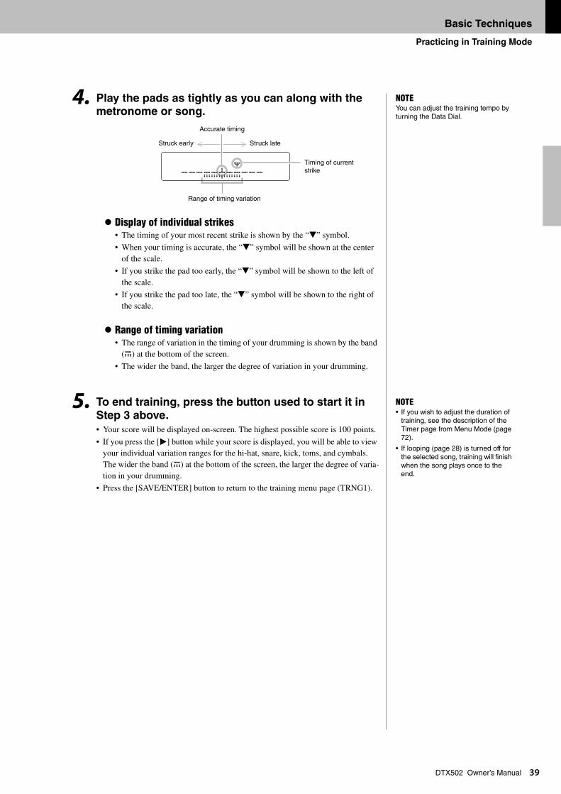
DTX502 Owner’s Manual4. Play the pads as tightly as you can along with the metronome or song.
Display of individual strikes• The timing of your most recent strike is shown by the “t” symbol.
• When your timing is accurate, the “t” symbol will be shown at the center of the scale.
• If you strike the pad too early, the “t” symbol will be shown to the left of the scale.
• If you strike the pad too late, the “t” symbol will be shown to the right of the scale.
Range of timing variation• The range of variation in the timing of your drumming is shown by the band
(E) at the bottom of the screen.
• The wider the band, the larger the degree of variation in your drumming.
5. To end training, press the button used to start it in
Step 3 above.• Your score will be displayed on-screen. The highest possible score is 100 points.
• If you press the [>] button while your score is displayed, you will be able to view your individual variation ranges for the hi-hat, snare, kick, toms, and cymbals. The wider the band (E) at the bottom of the screen, the larger the degree of varia-tion in your drumming.
• Press the [SAVE/ENTER] button to return to the training menu page (TRNG1).
NOTEYou can adjust the training tempo by turning the Data Dial.
ª ---EEnEE---
Accurate timing
Struck late
Timing of current strike
Range of timing variation
Struck early
NOTE• If you wish to adjust the duration of
training, see the description of the Timer page from Menu Mode (page 72).
• If looping (page 28) is turned off for the selected song, training will finish when the song plays once to the end.
Basic Techniques
Practicing in Training Mode
40
DTX502 Owner’s ManualAs an aid to improving your timing, Rhythm Gate displays on-screen any variation in the timing of your drumming. If you do not strike a pad in time with the metronome or song, it will not pro-duce any sound. Two different training styles are available—the first uses the metronome; the sec-ond lets you play along with a song. When you have finished training, your score will be displayed on-screen.
Training procedure
1. Hold down the [SHIFT] button and press the [KIT] button to access Training Mode.
2. Turn the Data Dial to select “02:Rhythm Gate”.The [ ] and [ ] buttons will start flashing, indicating that the drum module is on standby to start training.
3. Press either the [ ] or [ ] button when you are
ready to go.If you press the [ ] button, the current song will be used for training. If you press the [ ] button, the metronome will be used.
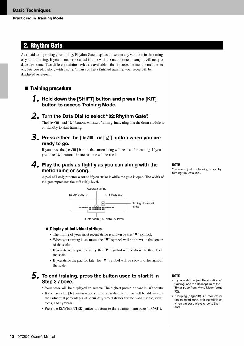
4. Play the pads as tightly as you can along with the
metronome or song. A pad will only produce a sound if you strike it while the gate is open. The width of the gate represents the difficultly level.
Display of individual strikes• The timing of your most recent strike is shown by the “t” symbol.
• When your timing is accurate, the “t” symbol will be shown at the center of the scale.
• If you strike the pad too early, the “t” symbol will be shown to the left of the scale.
• If you strike the pad too late, the “t” symbol will be shown to the right of the scale.
5. To end training, press the button used to start it in
Step 3 above.• Your score will be displayed on-screen. The highest possible score is 100 points.
• If you press the [>] button while your score is displayed, you will be able to view the individual percentages of accurately timed strikes for the hi-hat, snare, kick, toms, and cymbals.
• Press the [SAVE/ENTER] button to return to the training menu page (TRNG1).
2. Rhythm Gate
NOTEYou can adjust the training tempo by turning the Data Dial.
ª ---∆∆’∆∆---
Accurate timing
Struck late
Timing of current strike
Gate width (i.e., difficulty level)
Struck early
NOTE• If you wish to adjust the duration of
training, see the description of the Timer page from Menu Mode (page 72).
• If looping (page 28) is turned off for the selected song, training will finish when the song plays once to the end.
Basic Techniques
Practicing in Training Mode
41
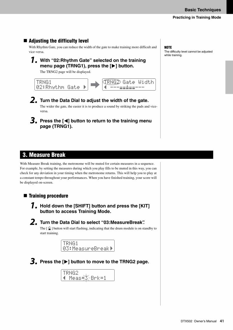
DTX502 Owner’s ManualAdjusting the difficulty levelWith Rhythm Gate, you can reduce the width of the gate to make training more difficult and vice-versa.
1. With “02:Rhythm Gate” selected on the training menu page (TRNG1), press the [>] button.
The TRNG2 page will be displayed.
2. Turn the Data Dial to adjust the width of the gate.
The wider the gate, the easier it is to produce a sound by striking the pads and vice-versa.
3. Press the [<] button to return to the training menu page (TRNG1).
With Measure Break training, the metronome will be muted for certain measures in a sequence. For example, by setting the measures during which you play fills to be muted in this way, you can check for any deviation in your timing when the metronome returns. This will help you to play at a constant tempo throughout your performances. When you have finished training, your score will be displayed on-screen.
Training procedure
1. Hold down the [SHIFT] button and press the [KIT]
button to access Training Mode.
2. Turn the Data Dial to select “03:MeasureBreak”.
The [ ] button will start flashing, indicating that the drum module is on standby to start training.
3. Press the [>] button to move to the TRNG2 page.
3. Measure Break
NOTEThe difficulty level cannot be adjusted while training.
tRNG102:Rhythm Gate ‚
tRNG2 Gate Width” ---∆∆’∆∆---
tRNG103:MeasureBreak‚
tRNG2” Meas=3 Brk=1
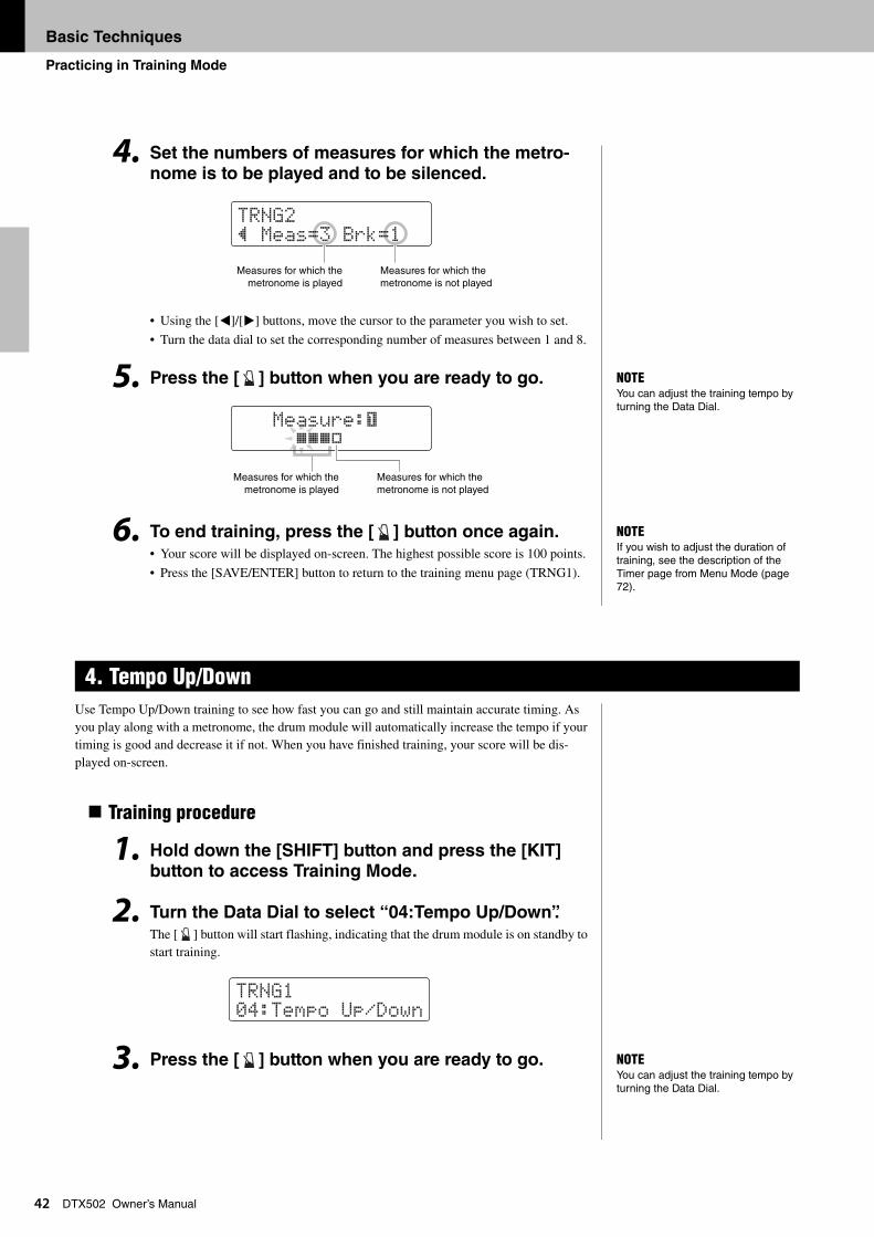
Basic Techniques
Practicing in Training Mode
42
DTX502 Owner’s Manual4. Set the numbers of measures for which the metro-nome is to be played and to be silenced.
• Using the [<]/[>] buttons, move the cursor to the parameter you wish to set.
• Turn the data dial to set the corresponding number of measures between 1 and 8.
5. Press the [ ] button when you are ready to go.
6. To end training, press the [ ] button once again.• Your score will be displayed on-screen. The highest possible score is 100 points.
• Press the [SAVE/ENTER] button to return to the training menu page (TRNG1).
Use Tempo Up/Down training to see how fast you can go and still maintain accurate timing. As you play along with a metronome, the drum module will automatically increase the tempo if your timing is good and decrease it if not. When you have finished training, your score will be dis-played on-screen.
Training procedure
1. Hold down the [SHIFT] button and press the [KIT] button to access Training Mode.
2. Turn the Data Dial to select “04:Tempo Up/Down”.The [ ] button will start flashing, indicating that the drum module is on standby to start training.
3. Press the [ ] button when you are ready to go.
4. Tempo Up/Down
tRNG2” Meas=3 Brk=1
Measures for which the metronome is not played
Measures for which themetronome is played
NOTEYou can adjust the training tempo by turning the Data Dial.
Measure:ƒ LLLK
Measures for which the metronome is not played
Measures for which themetronome is played
NOTEIf you wish to adjust the duration of training, see the description of the Timer page from Menu Mode (page 72).
tRNG104:tempo Up/Down
NOTEYou can adjust the training tempo by turning the Data Dial.
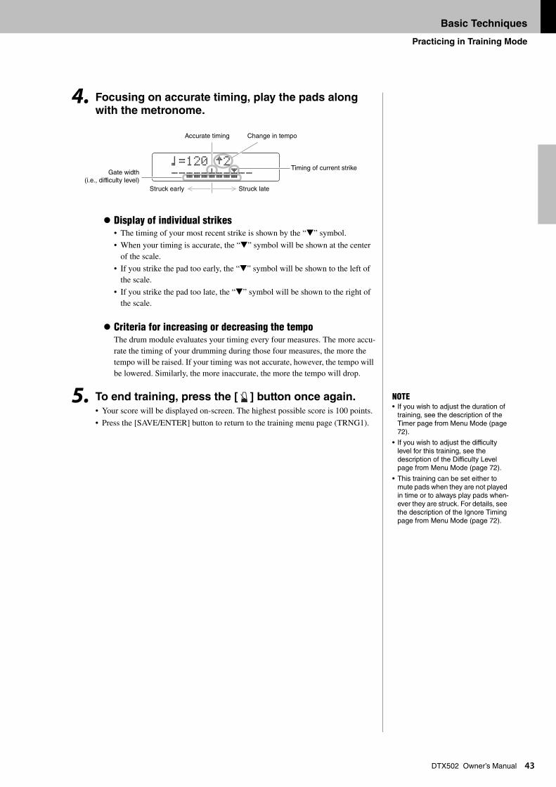
Basic Techniques
Practicing in Training Mode
43
DTX502 Owner’s Manual4. Focusing on accurate timing, play the pads along with the metronome.
Display of individual strikes• The timing of your most recent strike is shown by the “t” symbol.
• When your timing is accurate, the “t” symbol will be shown at the center of the scale.
• If you strike the pad too early, the “t” symbol will be shown to the left of the scale.
• If you strike the pad too late, the “t” symbol will be shown to the right of the scale.
Criteria for increasing or decreasing the tempoThe drum module evaluates your timing every four measures. The more accu-rate the timing of your drumming during those four measures, the more the tempo will be raised. If your timing was not accurate, however, the tempo will be lowered. Similarly, the more inaccurate, the more the tempo will drop.
5. To end training, press the [ ] button once again.• Your score will be displayed on-screen. The highest possible score is 100 points.
• Press the [SAVE/ENTER] button to return to the training menu page (TRNG1).
⁄=120 g2 --∆∆∆’∆∆O--
Accurate timing Change in tempo
Timing of current strike
Struck lateStruck early
Gate width(i.e., difficulty level)
NOTE• If you wish to adjust the duration of
training, see the description of the Timer page from Menu Mode (page 72).
• If you wish to adjust the difficulty level for this training, see the description of the Difficulty Level page from Menu Mode (page 72).
• This training can be set either to mute pads when they are not played in time or to always play pads when-ever they are struck. For details, see the description of the Ignore Timing page from Menu Mode (page 72).
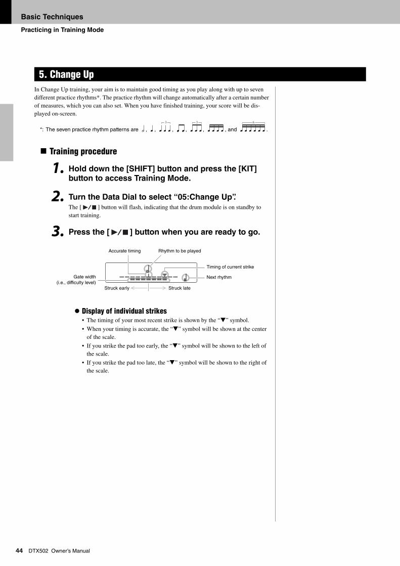
Basic Techniques
Practicing in Training Mode
44
DTX502 Owner’s ManualIn Change Up training, your aim is to maintain good timing as you play along with up to seven different practice rhythms*. The practice rhythm will change automatically after a certain number of measures, which you can also set. When you have finished training, your score will be dis-played on-screen.
*: The seven practice rhythm patterns are , , , , , , and .
Training procedure
1. Hold down the [SHIFT] button and press the [KIT]
button to access Training Mode.
2. Turn the Data Dial to select “05:Change Up”.
The [ ] button will flash, indicating that the drum module is on standby to start training.
3. Press the [ ] button when you are ready to go.
Display of individual strikes• The timing of your most recent strike is shown by the “t” symbol.
• When your timing is accurate, the “t” symbol will be shown at the center of the scale.
• If you strike the pad too early, the “t” symbol will be shown to the left of the scale.
• If you strike the pad too late, the “t” symbol will be shown to the right of the scale.
5. Change Up
3 3 6
É --∆∆∆’∆∆O-- Ñ
Accurate timing Rhythm to be played
Timing of current strike
Struck lateStruck early
Gate width(i.e., difficulty level)
Next rhythm
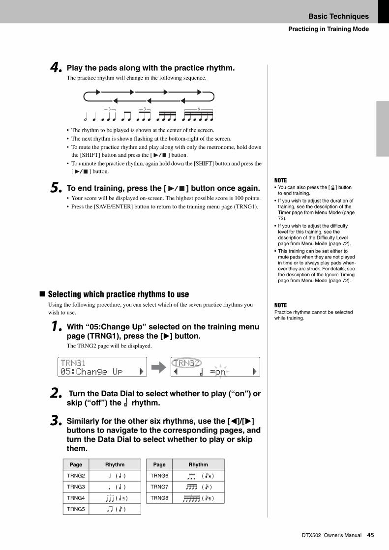
Basic Techniques
Practicing in Training Mode
45
DTX502 Owner’s Manual4. Play the pads along with the practice rhythm.The practice rhythm will change in the following sequence.
• The rhythm to be played is shown at the center of the screen.
• The next rhythm is shown flashing at the bottom-right of the screen.
• To mute the practice rhythm and play along with only the metronome, hold down the [SHIFT] button and press the [ ] button.
• To unmute the practice rhythm, again hold down the [SHIFT] button and press the [ ] button.
5. To end training, press the [ ] button once again.• Your score will be displayed on-screen. The highest possible score is 100 points.
• Press the [SAVE/ENTER] button to return to the training menu page (TRNG1).
Selecting which practice rhythms to useUsing the following procedure, you can select which of the seven practice rhythms you wish to use.
1. With “05:Change Up” selected on the training menu page (TRNG1), press the [>] button.The TRNG2 page will be displayed.
2. Turn the Data Dial to select whether to play (“on”) or skip (“off”) the É rhythm.
3. Similarly for the other six rhythms, use the [<]/[>] buttons to navigate to the corresponding pages, and turn the Data Dial to select whether to play or skip
them.
Page Rhythm Page Rhythm
TRNG2 ( É ) TRNG6 ( èA)
TRNG3 ( Ñ ) TRNG7 ( ê )
TRNG4 ( ÑA) TRNG8 ( êB)
TRNG5 ( è )
3 63
NOTE• You can also press the [ ] button
to end training.
• If you wish to adjust the duration of training, see the description of the Timer page from Menu Mode (page 72).
• If you wish to adjust the difficulty level for this training, see the description of the Difficulty Level page from Menu Mode (page 72).
• This training can be set either to mute pads when they are not played in time or to always play pads when-ever they are struck. For details, see the description of the Ignore Timing page from Menu Mode (page 72).
NOTEPractice rhythms cannot be selected while training.
tRNG105:Change Up ‚
tRNG2” É =on ‚
3
3 6
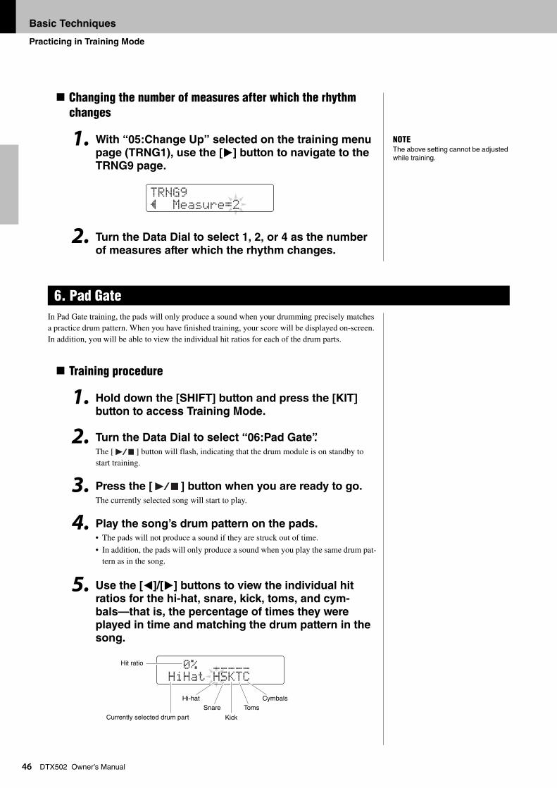
Basic Techniques
Practicing in Training Mode
46
DTX502 Owner’s ManualChanging the number of measures after which the rhythm changes
1. With “05:Change Up” selected on the training menu page (TRNG1), use the [>] button to navigate to the TRNG9 page.
2. Turn the Data Dial to select 1, 2, or 4 as the number
of measures after which the rhythm changes.
In Pad Gate training, the pads will only produce a sound when your drumming precisely matches a practice drum pattern. When you have finished training, your score will be displayed on-screen. In addition, you will be able to view the individual hit ratios for each of the drum parts.
Training procedure
1. Hold down the [SHIFT] button and press the [KIT]
button to access Training Mode.
2. Turn the Data Dial to select “06:Pad Gate”.
The [ ] button will flash, indicating that the drum module is on standby to start training.
3. Press the [ ] button when you are ready to go.
The currently selected song will start to play.
4. Play the song’s drum pattern on the pads. • The pads will not produce a sound if they are struck out of time.
• In addition, the pads will only produce a sound when you play the same drum pat-tern as in the song.
5. Use the [<]/[>] buttons to view the individual hit ratios for the hi-hat, snare, kick, toms, and cym-
bals—that is, the percentage of times they were played in time and matching the drum pattern in the song.
6. Pad Gate
NOTEThe above setting cannot be adjusted while training.
tRNG9” Measure=2
0% ¢¢¢¢¢ HiHat HSKtC
Cymbals
Hit ratio
Hi-hatSnare Toms
KickCurrently selected drum part
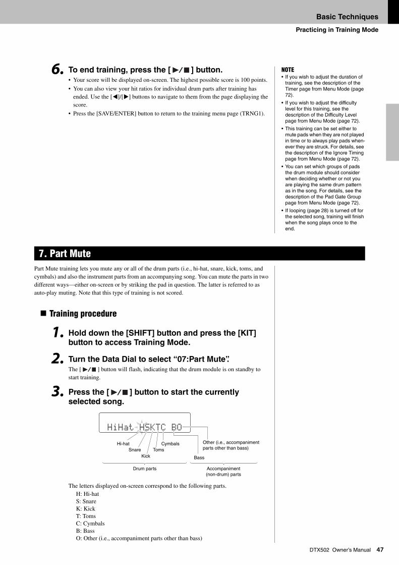
Basic Techniques
Practicing in Training Mode
47
DTX502 Owner’s Manual6. To end training, press the [ ] button. • Your score will be displayed on-screen. The highest possible score is 100 points.
• You can also view your hit ratios for individual drum parts after training has ended. Use the [<]/[>] buttons to navigate to them from the page displaying the score.
• Press the [SAVE/ENTER] button to return to the training menu page (TRNG1).
Part Mute training lets you mute any or all of the drum parts (i.e., hi-hat, snare, kick, toms, and cymbals) and also the instrument parts from an accompanying song. You can mute the parts in two different ways—either on-screen or by striking the pad in question. The latter is referred to as auto-play muting. Note that this type of training is not scored.
Training procedure
1. Hold down the [SHIFT] button and press the [KIT] button to access Training Mode.
2. Turn the Data Dial to select “07:Part Mute”.The [ ] button will flash, indicating that the drum module is on standby to start training.
3. Press the [ ] button to start the currently
selected song.
The letters displayed on-screen correspond to the following parts. H: Hi-hat S: SnareK: KickT: TomsC: CymbalsB: BassO: Other (i.e., accompaniment parts other than bass)
7. Part Mute
NOTE• If you wish to adjust the duration of
training, see the description of the Timer page from Menu Mode (page 72).
• If you wish to adjust the difficulty level for this training, see the description of the Difficulty Level page from Menu Mode (page 72).
• This training can be set either to mute pads when they are not played in time or to always play pads when-ever they are struck. For details, see the description of the Ignore Timing page from Menu Mode (page 72).
• You can set which groups of pads the drum module should consider when deciding whether or not you are playing the same drum pattern as in the song. For details, see the description of the Pad Gate Group page from Menu Mode (page 72).
• If looping (page 28) is turned off for the selected song, training will finish when the song plays once to the end.
HiHat HSKtC BO
Bass
Hi-hat CymbalsSnare Toms
Kick
Other (i.e., accompaniment parts other than bass)
Drum parts Accompaniment (non-drum) parts
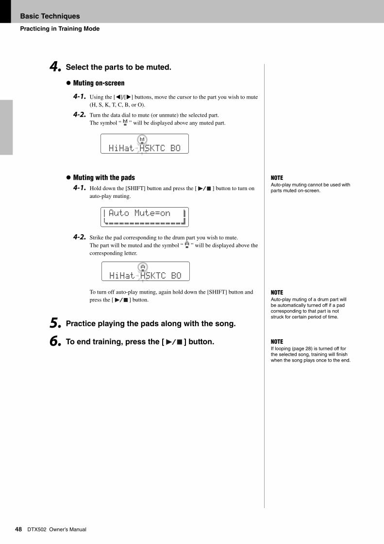
Basic Techniques
Practicing in Training Mode
48
DTX502 Owner’s Manual4. Select the parts to be muted.
Muting on-screen
4-1. Using the [<]/[>] buttons, move the cursor to the part you wish to mute (H, S, K, T, C, B, or O).
4-2. Turn the data dial to mute (or unmute) the selected part. The symbol “ M ” will be displayed above any muted part.
Muting with the pads4-1. Hold down the [SHIFT] button and press the [ ] button to turn on
auto-play muting.
4-2. Strike the pad corresponding to the drum part you wish to mute. The part will be muted and the symbol “ N ” will be displayed above the corresponding letter.
To turn off auto-play muting, again hold down the [SHIFT] button and press the [ ] button.
5. Practice playing the pads along with the song.
6. To end training, press the [ ] button.
M HiHat HSKtC BO
NOTEAuto-play muting cannot be used with parts muted on-screen.
aAuto Mute=on bcÇÇÇÇÇÇÇÇÇÇÇÇÇÇd
N HiHat HSKtC BO
NOTEAuto-play muting of a drum part will be automatically turned off if a pad corresponding to that part is not struck for certain period of time.
NOTEIf looping (page 28) is turned off for the selected song, training will finish when the song plays once to the end.
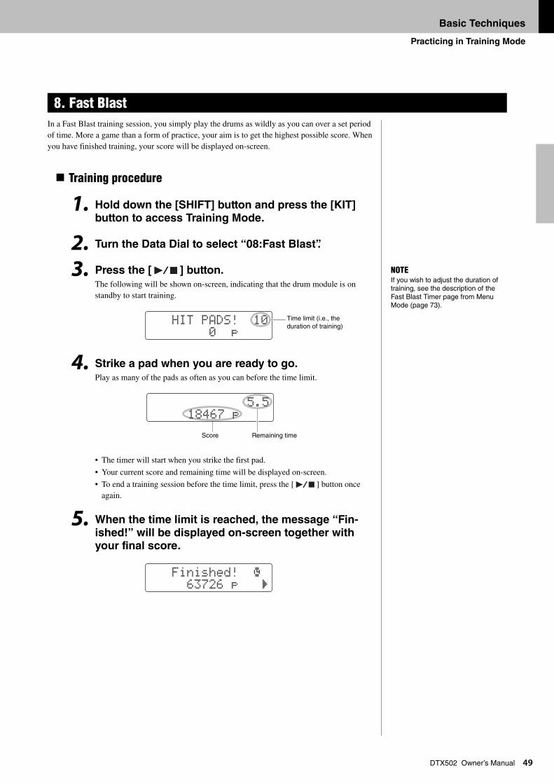
Basic Techniques
Practicing in Training Mode
49
DTX502 Owner’s ManualIn a Fast Blast training session, you simply play the drums as wildly as you can over a set period of time. More a game than a form of practice, your aim is to get the highest possible score. When you have finished training, your score will be displayed on-screen.
Training procedure
1. Hold down the [SHIFT] button and press the [KIT]
button to access Training Mode.
2. Turn the Data Dial to select “08:Fast Blast”.
3. Press the [ ] button.
The following will be shown on-screen, indicating that the drum module is on standby to start training.
4. Strike a pad when you are ready to go.Play as many of the pads as often as you can before the time limit.
• The timer will start when you strike the first pad.
• Your current score and remaining time will be displayed on-screen.
• To end a training session before the time limit, press the [ ] button once again.
5. When the time limit is reached, the message “Fin-
ished!” will be displayed on-screen together with your final score.
8. Fast Blast
NOTEIf you wish to adjust the duration of training, see the description of the Fast Blast Timer page from Menu Mode (page 73).
HIt PADS! 10 0 p
Time limit (i.e., the duration of training)
5.5 18467 p
Score Remaining time
Finished! º 63726 p ‚
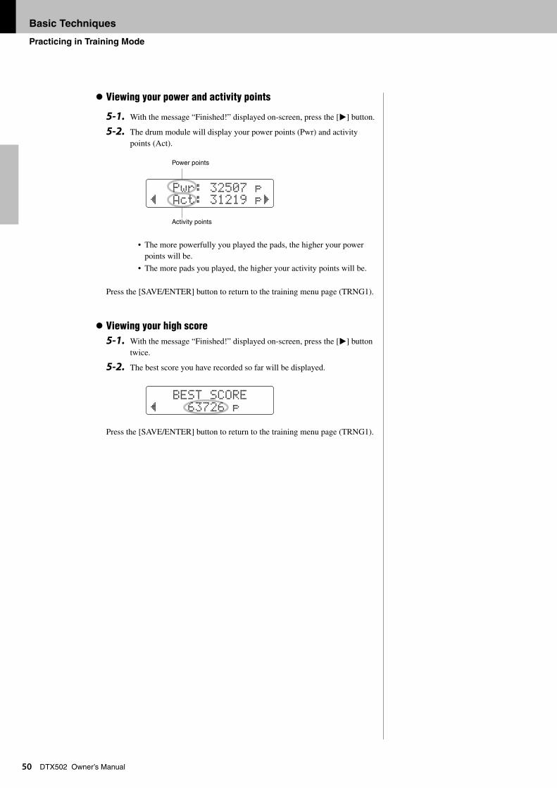
Basic Techniques
Practicing in Training Mode
50
DTX502 Owner’s ManualViewing your power and activity points
5-1. With the message “Finished!” displayed on-screen, press the [>] button.
5-2. The drum module will display your power points (Pwr) and activity points (Act).
• The more powerfully you played the pads, the higher your power points will be.
• The more pads you played, the higher your activity points will be.
Press the [SAVE/ENTER] button to return to the training menu page (TRNG1).
Viewing your high score5-1. With the message “Finished!” displayed on-screen, press the [>] button
twice.
5-2. The best score you have recorded so far will be displayed.
Press the [SAVE/ENTER] button to return to the training menu page (TRNG1).
Pwr: 32507 p” Act: 31219 p‚
Power points
Activity points
BESt SCORE” 63726 p
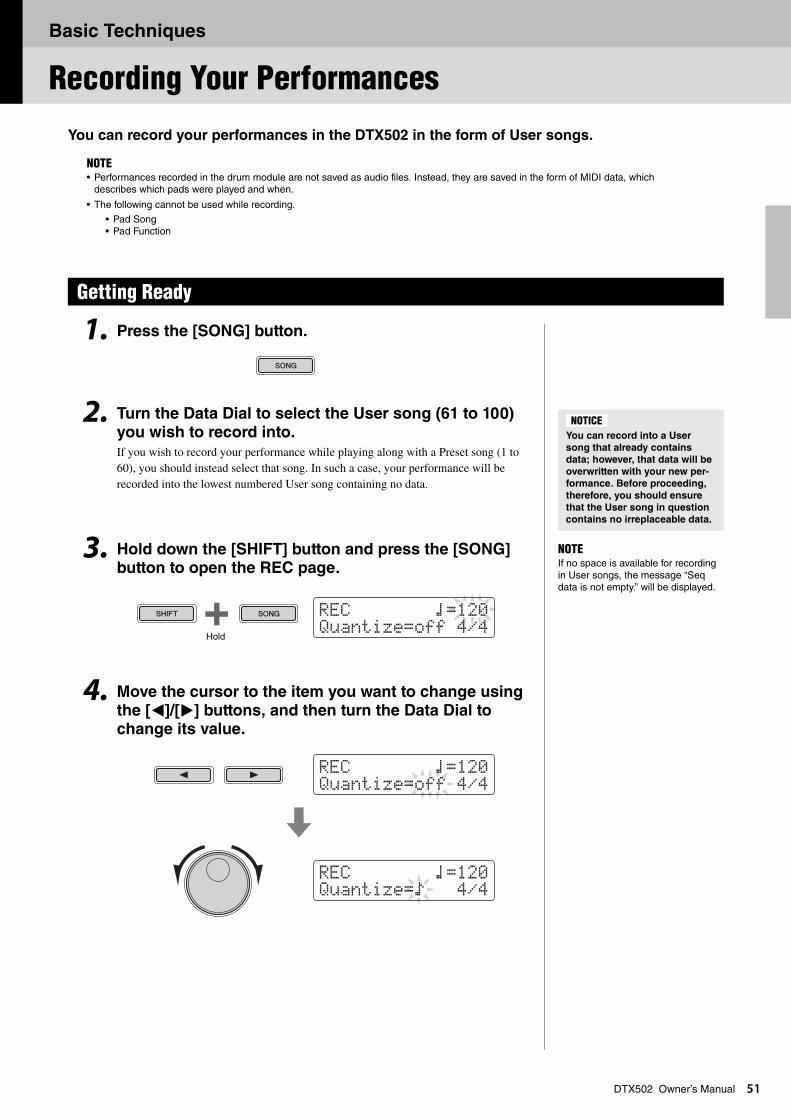
Basic Techniques
Recording Your Performances
51
DTX502 Owner’s ManualYou can record your performances in the DTX502 in the form of User songs.
1. Press the [SONG] button.
2. Turn the Data Dial to select the User song (61 to 100)
you wish to record into.If you wish to record your performance while playing along with a Preset song (1 to 60), you should instead select that song. In such a case, your performance will be recorded into the lowest numbered User song containing no data.
3. Hold down the [SHIFT] button and press the [SONG] button to open the REC page.
4. Move the cursor to the item you want to change using
the [<]/[>] buttons, and then turn the Data Dial to change its value.
NOTE• Performances recorded in the drum module are not saved as audio files. Instead, they are saved in the form of MIDI data, which
describes which pads were played and when.
• The following cannot be used while recording.
• Pad Song• Pad Function
Getting Ready
You can record into a User
song that already contains
data; however, that data will be
overwritten with your new per-
formance. Before proceeding,
therefore, you should ensure
that the User song in question
contains no irreplaceable data.
NOTICE
NOTEIf no space is available for recording in User songs, the message “Seq data is not empty.” will be displayed.
REC ⁄=120Quantize=off 4/4
Hold
REC ⁄=120Quantize=off 4/4
REC ⁄=120Quantize=Ö 4/4
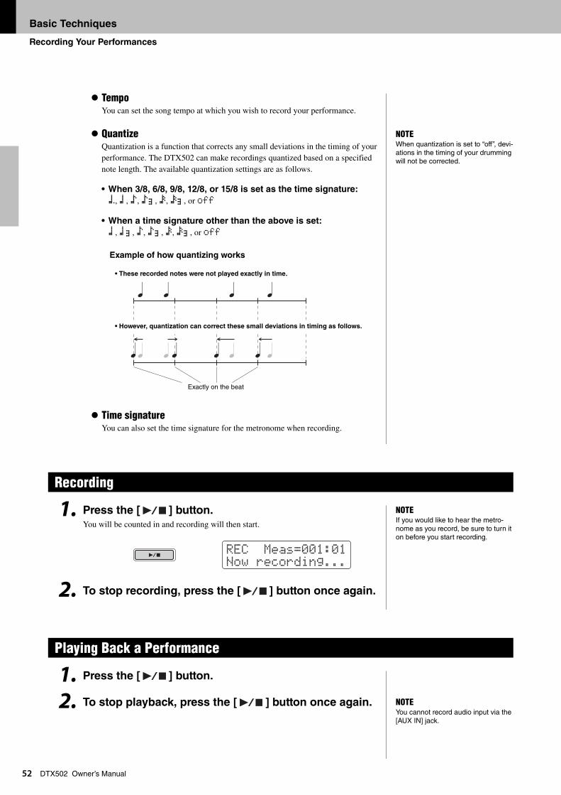
Basic Techniques
Recording Your Performances
52
DTX502 Owner’s ManualTempoYou can set the song tempo at which you wish to record your performance.
QuantizeQuantization is a function that corrects any small deviations in the timing of your performance. The DTX502 can make recordings quantized based on a specified note length. The available quantization settings are as follows.
• When 3/8, 6/8, 9/8, 12/8, or 15/8 is set as the time signature:
á, ⁄, Ö, ÖA, Ü, ÜA, or off
• When a time signature other than the above is set:
⁄, ⁄A, Ö, ÖA, Ü, ÜA, or off
Example of how quantizing works
Time signatureYou can also set the time signature for the metronome when recording.
1. Press the [ ] button.You will be counted in and recording will then start.
2. To stop recording, press the [ ] button once again.
1. Press the [ ] button.
2. To stop playback, press the [ ] button once again.
Recording
Playing Back a Performance
NOTEWhen quantization is set to “off”, devi-ations in the timing of your drumming will not be corrected.
• These recorded notes were not played exactly in time.
• However, quantization can correct these small deviations in timing as follows.
Exactly on the beat
NOTEIf you would like to hear the metro-nome as you record, be sure to turn it on before you start recording.
REC Meas=001:01Now recording...
NOTEYou cannot record audio input via the [AUX IN] jack.
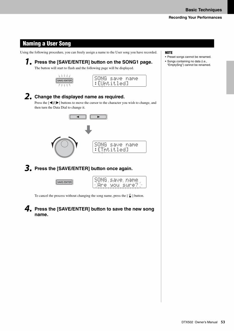
Basic Techniques
Recording Your Performances
53
DTX502 Owner’s ManualUsing the following procedure, you can freely assign a name to the User song you have recorded.
1. Press the [SAVE/ENTER] button on the SONG1 page. The button will start to flash and the following page will be displayed.
2. Change the displayed name as required.Press the [<]/[>] buttons to move the cursor to the character you wish to change, and then turn the Data Dial to change it.
3. Press the [SAVE/ENTER] button once again.
To cancel the process without changing the song name, press the [ ] button.
4. Press the [SAVE/ENTER] button to save the new song
name.
Naming a User SongNOTE• Preset songs cannot be renamed.
• Songs containing no data (i.e., “EmptySng”) cannot be renamed.
SONG saVe name:[Untitled]
SONG saVe name:[tntitled]
SONG saVe name Are you sure?
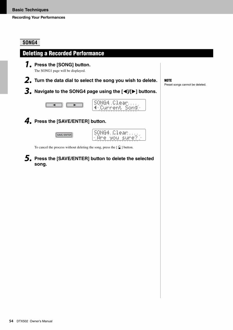
Basic Techniques
Recording Your Performances
54
DTX502 Owner’s Manual1. Press the [SONG] button.The SONG1 page will be displayed.
2. Turn the data dial to select the song you wish to delete.
3. Navigate to the SONG4 page using the [<]/[>] buttons.
4. Press the [SAVE/ENTER] button.
To cancel the process without deleting the song, press the [ ] button.
5. Press the [SAVE/ENTER] button to delete the selected song.
SONG4
Deleting a Recorded Performance
NOTEPreset songs cannot be deleted.
SONG4 Clear” Current Song
SONG4 Clear Are you sure?
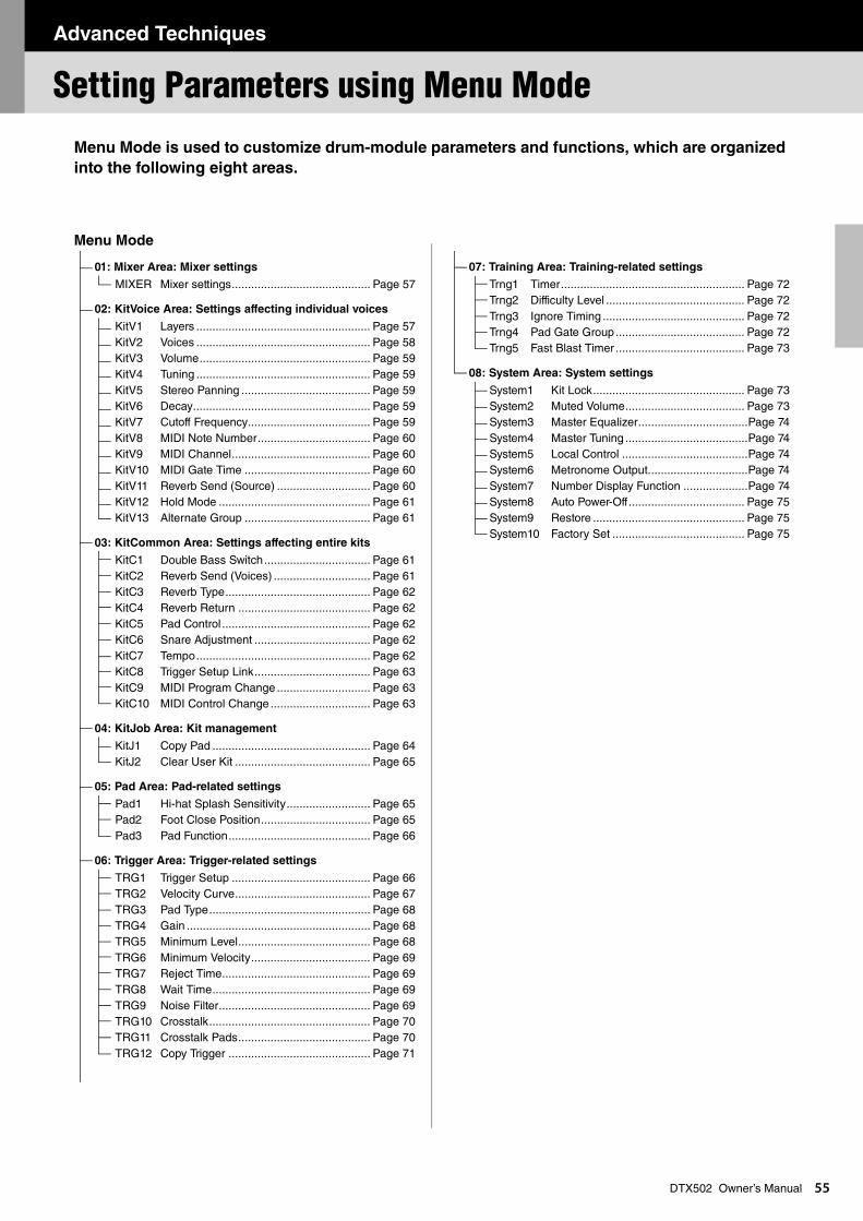
Advanced Techniques
Advanced Techniques
Setting Parameters using Menu Mode
55
DTX502 Owner’s ManualMenu Mode is used to customize drum-module parameters and functions, which are organized
into the following eight areas.
Menu Mode
01: Mixer Area: Mixer settings
MIXER Mixer settings........................................... Page 57
02: KitVoice Area: Settings affecting individual voices
KitV1 Layers ...................................................... Page 57KitV2 Voices ...................................................... Page 58KitV3 Volume..................................................... Page 59KitV4 Tuning ...................................................... Page 59KitV5 Stereo Panning ........................................ Page 59KitV6 Decay....................................................... Page 59KitV7 Cutoff Frequency...................................... Page 59KitV8 MIDI Note Number................................... Page 60KitV9 MIDI Channel........................................... Page 60KitV10 MIDI Gate Time ....................................... Page 60KitV11 Reverb Send (Source) ............................. Page 60KitV12 Hold Mode ............................................... Page 61KitV13 Alternate Group ....................................... Page 61
03: KitCommon Area: Settings affecting entire kits
KitC1 Double Bass Switch................................. Page 61KitC2 Reverb Send (Voices) .............................. Page 61KitC3 Reverb Type............................................. Page 62KitC4 Reverb Return ......................................... Page 62KitC5 Pad Control .............................................. Page 62KitC6 Snare Adjustment .................................... Page 62KitC7 Tempo...................................................... Page 62KitC8 Trigger Setup Link.................................... Page 63KitC9 MIDI Program Change ............................. Page 63KitC10 MIDI Control Change ............................... Page 63
04: KitJob Area: Kit management
KitJ1 Copy Pad ................................................. Page 64KitJ2 Clear User Kit .......................................... Page 65
05: Pad Area: Pad-related settings
Pad1 Hi-hat Splash Sensitivity.......................... Page 65Pad2 Foot Close Position.................................. Page 65Pad3 Pad Function............................................ Page 66
06: Trigger Area: Trigger-related settings
TRG1 Trigger Setup ........................................... Page 66TRG2 Velocity Curve.......................................... Page 67TRG3 Pad Type.................................................. Page 68TRG4 Gain ......................................................... Page 68TRG5 Minimum Level......................................... Page 68TRG6 Minimum Velocity..................................... Page 69TRG7 Reject Time.............................................. Page 69TRG8 Wait Time................................................. Page 69TRG9 Noise Filter............................................... Page 69TRG10 Crosstalk.................................................. Page 70TRG11 Crosstalk Pads......................................... Page 70TRG12 Copy Trigger ............................................ Page 71
07: Training Area: Training-related settings
Trng1 Timer......................................................... Page 72Trng2 Difficulty Level ........................................... Page 72Trng3 Ignore Timing ............................................ Page 72Trng4 Pad Gate Group........................................ Page 72Trng5 Fast Blast Timer ........................................ Page 73
08: System Area: System settings
System1 Kit Lock............................................... Page 73System2 Muted Volume..................................... Page 73System3 Master Equalizer..................................Page 74System4 Master Tuning ......................................Page 74System5 Local Control .......................................Page 74System6 Metronome Output...............................Page 74System7 Number Display Function ....................Page 74System8 Auto Power-Off.................................... Page 75System9 Restore ............................................... Page 75System10 Factory Set ......................................... Page 75
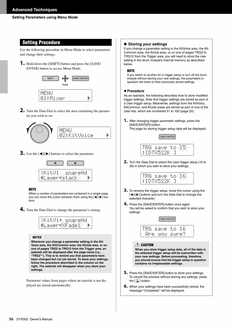
Advanced Techniques
Setting Parameters using Menu Mode
56
DTX502 Owner’s ManualUse the following procedure in Menu Mode to select parameters and change their settings.
1. Hold down the [SHIFT] button and press the [SAVE/ENTER] button to access Menu Mode.
2. Turn the Data Dial to select the area containing the parame-ter you wish to set.
3. Use the [<]/[>] buttons to select the parameter.
4. Turn the Data Dial to change the parameter’s setting.
Parameter values from pages where an asterisk is not dis-played are stored automatically.
Setting Procedure
NOTEWhen a number of parameters are contained in a single page, you can move the cursor between them using the [<]/[>] but-tons.
Whenever you change a parameter setting in the Kit-
Voice area, the KitCommon area, the KitJob area, or on
one of pages TRG2 to TRG12 from the Trigger area, an
asterisk will be displayed after the page name (i.e.,
“TRG2*”). This is to remind you that parameters have
been changed but not yet stored. To store your settings,
follow the procedure described in the column on the
right. The asterisk will disappear when you store your
settings.
MENU01:Mixer ‚
Hold
MENU02:KitVoice ‚
>KitV1 snareHd”Layer=stack ‚
>KitV1* snareHd”Layer=XFade1 ‚
NOTICE
Storing your settingsIf you change a parameter setting in the KitVoice area, the Kit-Common area, the KitJob area, or on one of pages TRG2 to TRG12 from the Trigger area, you will need to store the new setting in the drum module’s internal memory as described below.
Procedure
As an example, the following describes how to store modified trigger settings. Note that trigger settings are stored as part of a User trigger setup. Meanwhile, settings from the KitVoice, KitCommon, and KitJob areas are stored as part of one of the User kits, which are numbered 51 to 100 (page 25).
1. After changing trigger parameter settings, press the [SAVE/ENTER] button.The page for storing trigger setup data will be displayed.
2. Turn the Data Dial to select the User trigger setup (15 to 30) in which you wish to store your settings.
3. To rename the trigger setup, move the cursor using the [<]/[>] buttons and turn the Data Dial to change the selected character.
4. Press the [SAVE/ENTER] button once again.You will be asked to confirm that you wish to store your settings.
5. Press the [SAVE/ENTER] button to store your settings. To cancel the process without storing any settings, press the [ ] button.
6. When your settings have been successfully stored, the message “Completed.” will be displayed.
NOTEIf you switch to another kit or trigger setup or turn off the drum module without storing your new settings, the parameters in question will revert to their previously stored settings.
tRG saVe to 15:[DtX522K ]
tRG saVe to 16:[DtX522K ]
tRG saVe to 16 Are you sure?
CAUTIONWhen you store trigger setup data, all of the data in
the selected trigger setup will be overwritten with
your new settings. Before proceeding, therefore,
you should ensure that the trigger setup in question
contains no irreplaceable settings.

Advanced Techniques
Setting Parameters using Menu Mode
57
DTX502 Owner’s ManualThe Mixer area is used to adjust the volumes of the various drum kit voices.
MIXER Mixer settings
q Volume
Use the volume parameters to balance the input group* vol-umes.
Input group indicators
H: Hi-hat sound volumesS: Snare sound volumesK: Kick sound volumesT: Tom sound volumesC: Cymbal sound volumesR: Degree to which reverb is applied
Use the [<]/[>] buttons to select an input group, and then turn the Data Dial to adjust its volume. Faders are displayed above each of the input-group indicators to give a general idea of the current volume balance. The reverb (R) setting applies to all of the drum kit’s voices.
The KitVoice area is used to set drum voices for individual trigger input sources.
KitV1 Layers
q Trigger input source
This item indicates the trigger input source currently selected for editing. Trigger input sources can be selected by striking the corresponding pad or zone. This selection applies to both Layer A and Layer B. (Trigger input sources are not dis-played individually for each layer.)
01: Mixer Area
Mixer settings
NOTE*: Input groups
Voices are organized into input groups based on their voice category. For example, when you change the T setting (tom sound volumes), the volume of all sounds from the Tom (T) voice category will change accordingly.
Settings 0 to 16
>MIXER ÏÏÏÏÏÈ” Kick=16 HSKtCR
q
02: KitVoice Area
Settings affecting individual voices
NOTEYou can also select trigger input sources by holding down the [SHIFT] button and pressing the [<]/[>] buttons.
Settings
snareHd, snareOp, snareCl, snrOfHd, snrOfOp, snrOfCl, tom1Hd, tom2Hd, tom3Hd, rideBw, rideEg, rideCp, crashBw, crashEg, crashCp, kick, pad8, hhOpBw, hhOpEg, hhOpCp, hhClBw, hhClEg, hhClCp, hhFtCl, hhSplsh, pad10, pad11, pad12, and kick2
For details on the correspondence between trigger input jacks and trigger input sources, refer to page 29.
>KitV1 snareHd”Layer=stack ‚
q
w
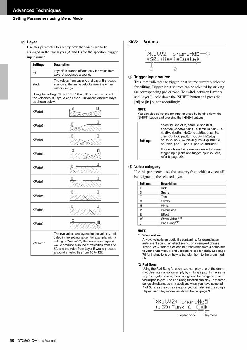
Advanced Techniques
Setting Parameters using Menu Mode
58
DTX502 Owner’s Manualw Layer
Use this parameter to specify how the voices are to be arranged in the two layers (A and B) for the specified trigger input source.
KitV2 Voices
q Trigger input source
This item indicates the trigger input source currently selected for editing. Trigger input sources can be selected by striking the corresponding pad or zone. To switch between Layer A and Layer B, hold down the [SHIFT] button and press the [<] or [>] button accordingly.
w Voice category
Use this parameter to set the category from which a voice will be assigned to the selected layer.
Settings Description
offLayer B is turned off and only the voice from Layer A produces a sound.
stackThe voices from Layer A and Layer B produce sounds at the same velocity over the entire velocity range.
Using the settings “XFade1” to “XFade9”, you can crossfade the velocities of Layer A and Layer B in various different ways as shown below.
XFade1
XFade2
XFade3
XFade4
XFade5
XFade6
XFade7
XFade8
XFade9
VelSw***
The two voices are layered at the velocity indi-cated in the setting value. For example, with a setting of “VelSw60”, the voice from Layer A would produce a sound at velocities from 1 to 59, and the voice from Layer B would produce a sound at velocities from 60 to 127.
NOTEYou can also select trigger input sources by holding down the [SHIFT] button and pressing the [<]/[>] buttons.
Settings
snareHd, snareOp, snareCl, snrOfHd, snrOfOp, snrOfCl, tom1Hd, tom2Hd, tom3Hd, rideBw, rideEg, rideCp, crashBw, crashEg, crashCp, kick, pad8, hhOpBw, hhOpEg, hhOpCp, hhClBw, hhClEg, hhClCp, hhFtCl, hhSplsh, pad10, pad11, pad12, and kick2
For details on the correspondence between trigger input jacks and trigger input sources, refer to page 29.
Settings DescriptionK KickS SnareT TomC CymbalH Hi-hatP PercussionE EffectW Wave Voice (*1)
e Pad Song (*2)
NOTE*1: Wave voices
A wave voice is an audio file containing, for example, an instrument sound, an effect sound, or a sampled phrase. These .WAV format files can be transferred from a computer to your drum module and used as voices for pads. See page 79 for instructions on how to transfer them to the drum mod-ule.
*2: Pad Song
Using the Pad Song function, you can play one of the drum module’s internal songs simply by striking a pad. In the same way as regular voices, these songs can be assigned to indi-vidual pad layers. The Pad Song function can play up to three songs simultaneously. In addition, when you have selected Pad Song as the voice category, you can also set the song’s Repeat and Play modes as shown below (page 30).
>KitV2 snareHd˙”S01:MapleCustm‚
q
w e
>KitV2* snareHd˙”Ö39:Funk C ≥‚
Repeat mode Play mode
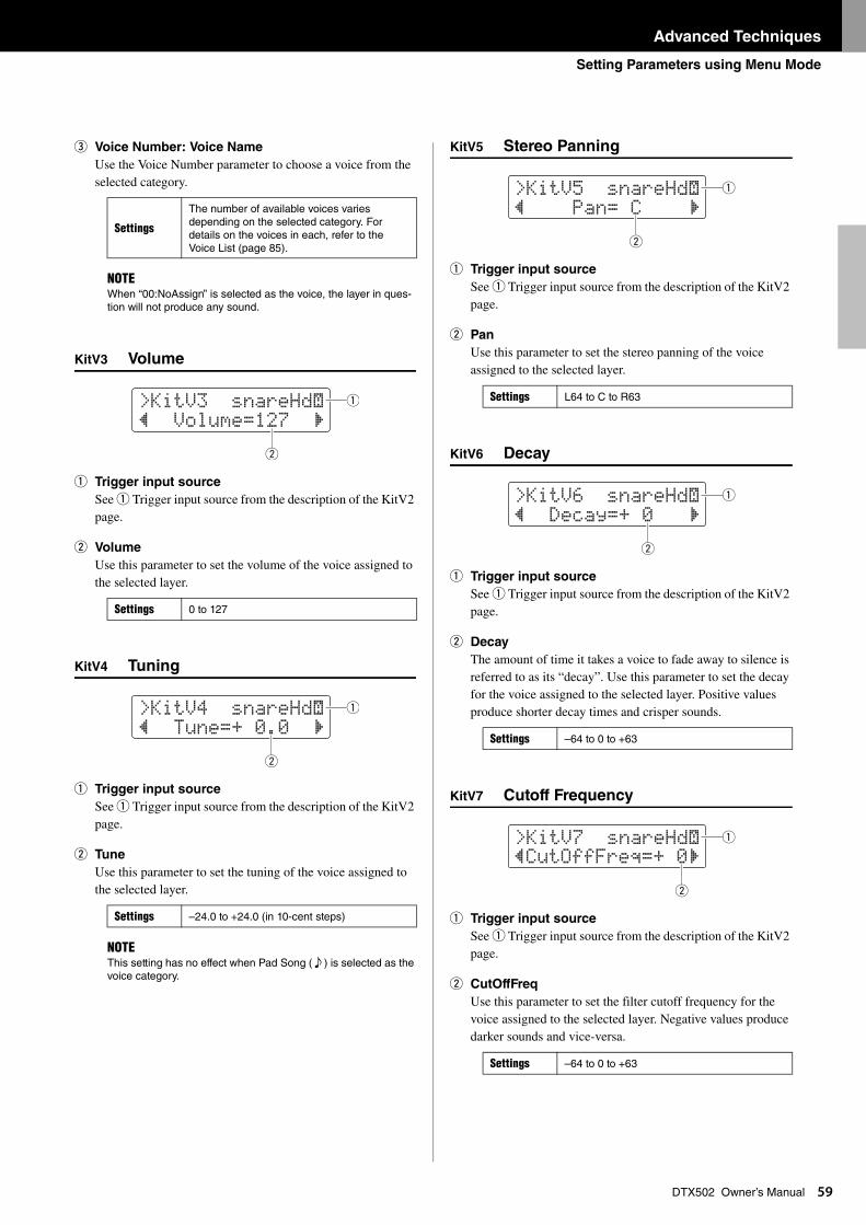
Advanced Techniques
Setting Parameters using Menu Mode
59
DTX502 Owner’s Manuale Voice Number: Voice Name
Use the Voice Number parameter to choose a voice from the selected category.
KitV3 Volume
q Trigger input source
See q Trigger input source from the description of the KitV2 page.
w Volume
Use this parameter to set the volume of the voice assigned to the selected layer.
KitV4 Tuning
q Trigger input source
See q Trigger input source from the description of the KitV2 page.
w Tune
Use this parameter to set the tuning of the voice assigned to the selected layer.
KitV5 Stereo Panning
q Trigger input source
See q Trigger input source from the description of the KitV2 page.
w Pan
Use this parameter to set the stereo panning of the voice assigned to the selected layer.
KitV6 Decay
q Trigger input source
See q Trigger input source from the description of the KitV2 page.
w Decay
The amount of time it takes a voice to fade away to silence is referred to as its “decay”. Use this parameter to set the decay for the voice assigned to the selected layer. Positive values produce shorter decay times and crisper sounds.
KitV7 Cutoff Frequency
q Trigger input source
See q Trigger input source from the description of the KitV2 page.
w CutOffFreq
Use this parameter to set the filter cutoff frequency for the voice assigned to the selected layer. Negative values produce darker sounds and vice-versa.
Settings
The number of available voices varies depending on the selected category. For details on the voices in each, refer to the Voice List (page 85).
NOTEWhen “00:NoAssign” is selected as the voice, the layer in ques-tion will not produce any sound.
Settings 0 to 127
Settings –24.0 to +24.0 (in 10-cent steps)
NOTEThis setting has no effect when Pad Song ( e ) is selected as the voice category.
>KitV3 snareHd˙” Volume=127 ‚
q
w
>KitV4 snareHd˙” tune=+ 0.0 ‚
q
w
Settings L64 to C to R63
Settings –64 to 0 to +63
Settings –64 to 0 to +63
>KitV5 snareHd˙” Pan= C ‚
q
w
>KitV6 snareHd˙” Decay=+ 0 ‚
q
w
>KitV7 snareHd˙”CutOffFreq=+ 0‚
q
w
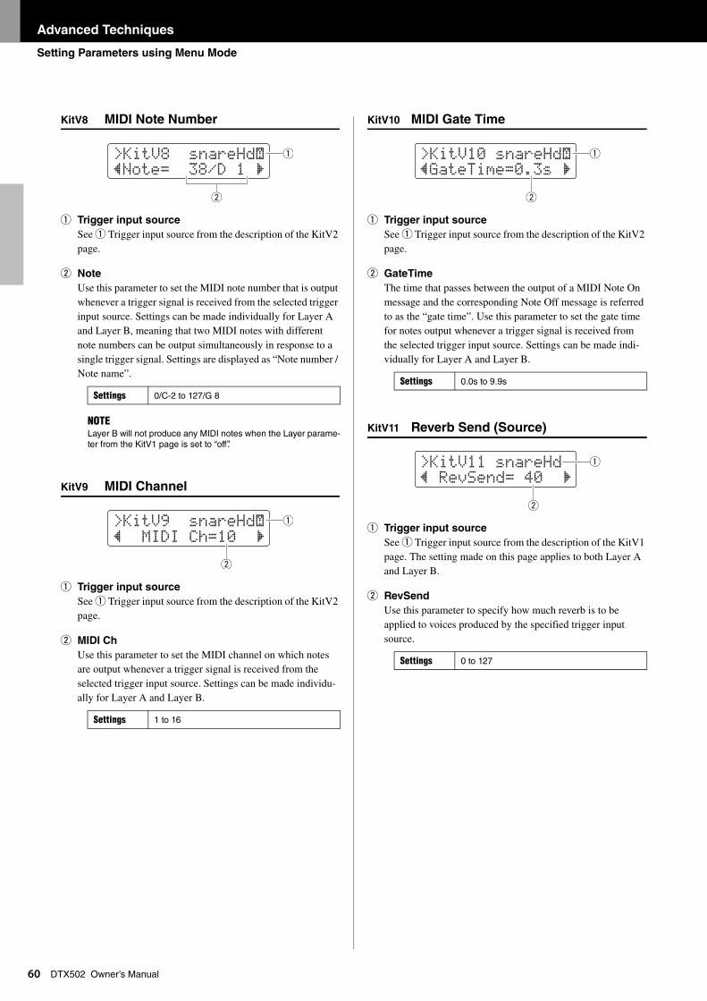
Advanced Techniques
Setting Parameters using Menu Mode
60
DTX502 Owner’s ManualKitV8 MIDI Note Number
q Trigger input source
See q Trigger input source from the description of the KitV2 page.
w Note
Use this parameter to set the MIDI note number that is output whenever a trigger signal is received from the selected trigger input source. Settings can be made individually for Layer A and Layer B, meaning that two MIDI notes with different note numbers can be output simultaneously in response to a single trigger signal. Settings are displayed as “Note number / Note name”.
KitV9 MIDI Channel
q Trigger input source
See q Trigger input source from the description of the KitV2 page.
w MIDI Ch
Use this parameter to set the MIDI channel on which notes are output whenever a trigger signal is received from the selected trigger input source. Settings can be made individu-ally for Layer A and Layer B.
KitV10 MIDI Gate Time
q Trigger input source
See q Trigger input source from the description of the KitV2 page.
w GateTime
The time that passes between the output of a MIDI Note On message and the corresponding Note Off message is referred to as the “gate time”. Use this parameter to set the gate time for notes output whenever a trigger signal is received from the selected trigger input source. Settings can be made indi-vidually for Layer A and Layer B.
KitV11 Reverb Send (Source)
q Trigger input source
See q Trigger input source from the description of the KitV1 page. The setting made on this page applies to both Layer A and Layer B.
w RevSend
Use this parameter to specify how much reverb is to be applied to voices produced by the specified trigger input source.
Settings 0/C-2 to 127/G 8
NOTELayer B will not produce any MIDI notes when the Layer parame-ter from the KitV1 page is set to “off”.
Settings 1 to 16
>KitV8 snareHd˙”Note= 38/D 1 ‚
q
w
>KitV9 snareHd˙” MIDI Ch=10 ‚
q
w
Settings 0.0s to 9.9s
Settings 0 to 127
>KitV10 snareHd˙”Gatetime=0.3s ‚
q
w
>KitV11 snareHd” ReVSend= 40 ‚
w
q
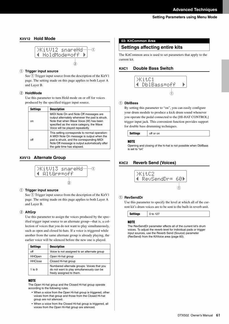
Advanced Techniques
Setting Parameters using Menu Mode
61
DTX502 Owner’s ManualKitV12 Hold Mode
q Trigger input source
See q Trigger input source from the description of the KitV1 page. The setting made on this page applies to both Layer A and Layer B.
w HoldMode
Use this parameter to turn Hold mode on or off for voices produced by the specified trigger input source.
KitV13 Alternate Group
q Trigger input source
See q Trigger input source from the description of the KitV1 page. The setting made on this page applies to both Layer A and Layer B.
w AltGrp
Use this parameter to assign the voices produced by the spec-ified trigger input source to an alternate group—that is, a col-lection of voices that you do not want to play simultaneously, such as open and closed hi-hats. If a voice is triggered while another from the same alternate group is already playing, the earlier voice will be silenced before the new one is played.
The KitCommon area is used to set parameters that apply to the current kit.
KitC1 Double Bass Switch
q DblBass
By setting this parameter to “on”, you can easily configure your drum module to produce a kick drum sound whenever you operate the pedal connected to the [HI-HAT CONTROL] trigger input jack. This convenient function provides support for double bass drumming techniques.
KitC2 Reverb Send (Voices)
q RevSendDr
Use this parameter to specify the level at which all of the cur-rent kit’s drum voices are to be sent to the built-in reverb unit.
Settings Description
on
MIDI Note On and Note Off messages are output alternately whenever the pad is struck. Note that when Wave Voice (W) has been specified as the voice category, the Wave Voice will be played repeatedly.
off
This setting corresponds to normal operation: A MIDI Note On message is output when the pad is struck, and the corresponding MIDI Note Off message is output automatically after the gate time has elapsed.
Settings Description
off Voice is not assigned to an alternate group
HHOpen Open Hi-hat group
HHClose Closed Hi-hat group
1 to 9Numbered alternate groups: Voices that you do not want to play simultaneously can be freely assigned to them.
NOTEThe Open Hi-hat group and the Closed Hi-hat group operate according to the following rules.
• When a voice from the Open Hi-hat group is triggered, other voices from that group and those from the Closed Hi-hat group are not silenced.
• When a voice from the Closed Hi-hat group is triggered, all voices from the Open Hi-Hat group are silenced.
>KitV12 snareHd” HoldMode=off ‚
w
q
>KitV13 snareHd” AltGrp=off
w
q
03: KitCommon Area
Settings affecting entire kits
Settings off or on
NOTEOpening and closing of the hi-hat is not possible when DblBass is set to “on”.
Settings 0 to 127
NOTEThe RevSendDr parameter affects all of the current kit’s drum voices. To adjust the reverb level for individual pads or trigger input sources, use the Reverb Send (Source) parameter (RevSend) from the KitVoice area (page 60).
>KitC1” DblBass=off ‚
q
>KitC2” ReVSendDr= 60‚
q
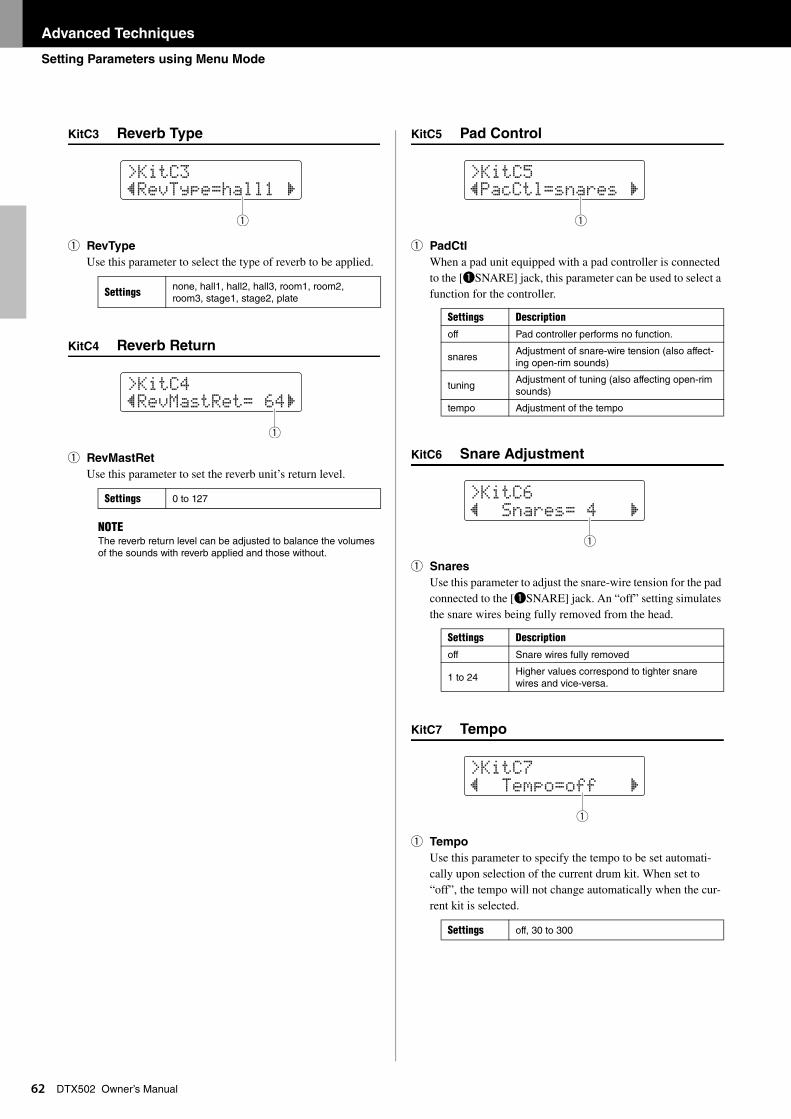
Advanced Techniques
Setting Parameters using Menu Mode
62
DTX502 Owner’s ManualKitC3 Reverb Type
q RevType
Use this parameter to select the type of reverb to be applied.
KitC4 Reverb Return
q RevMastRet
Use this parameter to set the reverb unit’s return level.
KitC5 Pad Control
q PadCtl
When a pad unit equipped with a pad controller is connected to the [qSNARE] jack, this parameter can be used to select a function for the controller.
KitC6 Snare Adjustment
q Snares
Use this parameter to adjust the snare-wire tension for the pad connected to the [qSNARE] jack. An “off” setting simulates the snare wires being fully removed from the head.
KitC7 Tempo
q Tempo
Use this parameter to specify the tempo to be set automati-cally upon selection of the current drum kit. When set to “off”, the tempo will not change automatically when the cur-rent kit is selected.
Settings none, hall1, hall2, hall3, room1, room2, room3, stage1, stage2, plate
Settings 0 to 127
NOTEThe reverb return level can be adjusted to balance the volumes of the sounds with reverb applied and those without.
>KitC3”ReVtype=hall1 ‚
q
>KitC4”ReVMastRet= 64‚
q
Settings Description
off Pad controller performs no function.
snaresAdjustment of snare-wire tension (also affect-ing open-rim sounds)
tuningAdjustment of tuning (also affecting open-rim sounds)
tempo Adjustment of the tempo
Settings Description
off Snare wires fully removed
1 to 24Higher values correspond to tighter snare wires and vice-versa.
Settings off, 30 to 300
>KitC5”PacCtl=snares ‚
q
>KitC6” Snares= 4 ‚
q
>KitC7” tempo=off ‚
q
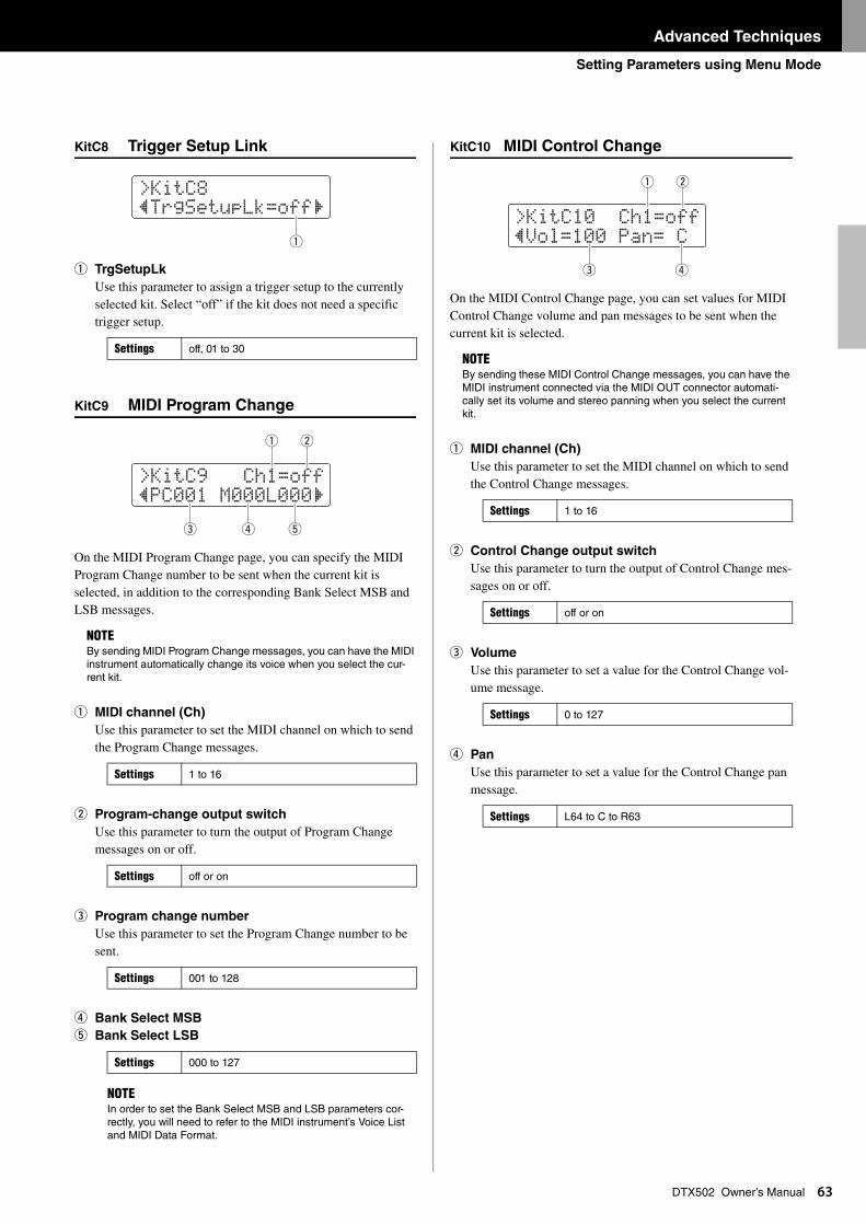
Advanced Techniques
Setting Parameters using Menu Mode
63
DTX502 Owner’s ManualKitC8 Trigger Setup Link
q TrgSetupLk
Use this parameter to assign a trigger setup to the currently selected kit. Select “off” if the kit does not need a specific trigger setup.
KitC9 MIDI Program Change
On the MIDI Program Change page, you can specify the MIDI Program Change number to be sent when the current kit is selected, in addition to the corresponding Bank Select MSB and LSB messages.
q MIDI channel (Ch)
Use this parameter to set the MIDI channel on which to send the Program Change messages.
w Program-change output switch
Use this parameter to turn the output of Program Change messages on or off.
e Program change number
Use this parameter to set the Program Change number to be sent.
r Bank Select MSB
t Bank Select LSB
KitC10 MIDI Control Change
On the MIDI Control Change page, you can set values for MIDI Control Change volume and pan messages to be sent when the current kit is selected.
q MIDI channel (Ch)
Use this parameter to set the MIDI channel on which to send the Control Change messages.
w Control Change output switch
Use this parameter to turn the output of Control Change mes-sages on or off.
e Volume
Use this parameter to set a value for the Control Change vol-ume message.
r Pan
Use this parameter to set a value for the Control Change pan message.
Settings off, 01 to 30
NOTEBy sending MIDI Program Change messages, you can have the MIDI instrument automatically change its voice when you select the cur-rent kit.
Settings 1 to 16
Settings off or on
Settings 001 to 128
Settings 000 to 127
NOTEIn order to set the Bank Select MSB and LSB parameters cor-rectly, you will need to refer to the MIDI instrument’s Voice List and MIDI Data Format.
>KitC8”trgSetupLk=off‚
q
>KitC9 Ch1=off”PC001 M000L000‚
te r
q w
NOTEBy sending these MIDI Control Change messages, you can have the MIDI instrument connected via the MIDI OUT connector automati-cally set its volume and stereo panning when you select the current kit.
Settings 1 to 16
Settings off or on
Settings 0 to 127
Settings L64 to C to R63
>KitC10 Ch1=off”Vol=100 Pan= C
e r
q w
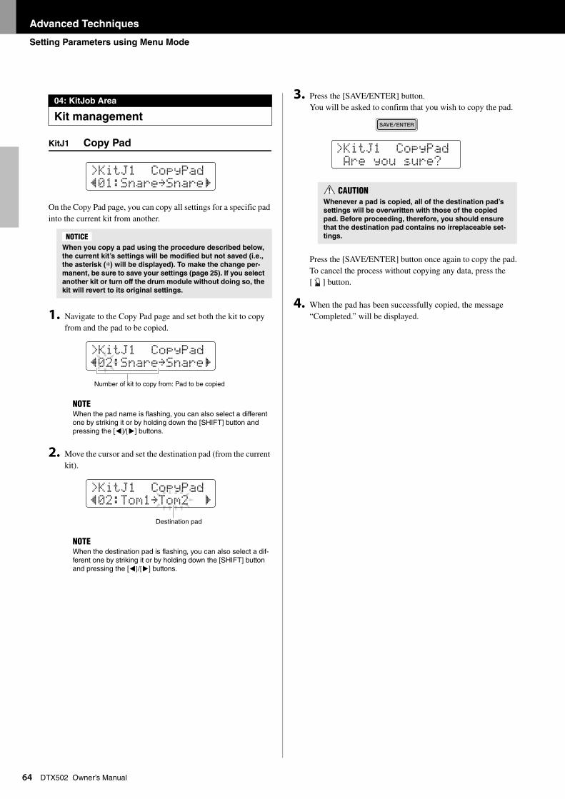
Advanced Techniques
Setting Parameters using Menu Mode
64
DTX502 Owner’s ManualKitJ1 Copy Pad
On the Copy Pad page, you can copy all settings for a specific pad into the current kit from another.
1. Navigate to the Copy Pad page and set both the kit to copy from and the pad to be copied.
2. Move the cursor and set the destination pad (from the current kit).
3. Press the [SAVE/ENTER] button. You will be asked to confirm that you wish to copy the pad.
Press the [SAVE/ENTER] button once again to copy the pad.To cancel the process without copying any data, press the [ ] button.
4. When the pad has been successfully copied, the message “Completed.” will be displayed.
04: KitJob Area
Kit management
When you copy a pad using the procedure described below,
the current kit’s settings will be modified but not saved (i.e.,
the asterisk (*) will be displayed). To make the change per-
manent, be sure to save your settings (page 25). If you select
another kit or turn off the drum module without doing so, the
kit will revert to its original settings.
NOTEWhen the pad name is flashing, you can also select a different one by striking it or by holding down the [SHIFT] button and pressing the [<]/[>] buttons.
NOTEWhen the destination pad is flashing, you can also select a dif-ferent one by striking it or by holding down the [SHIFT] button and pressing the [<]/[>] buttons.
>KitJ1 CopyPad”01:Snare≥Snare‚
NOTICE
>KitJ1 CopyPad”02:Snare≥Snare‚
Number of kit to copy from: Pad to be copied
>KitJ1 CopyPad”02:tom1≥tom2 ‚
Destination pad
CAUTIONWhenever a pad is copied, all of the destination pad’s
settings will be overwritten with those of the copied
pad. Before proceeding, therefore, you should ensure
that the destination pad contains no irreplaceable set-
tings.
>KitJ1 CopyPad Are you sure?
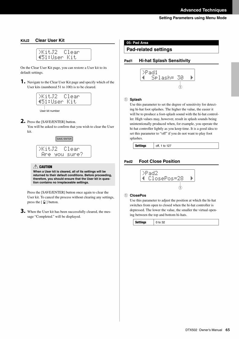
Advanced Techniques
Setting Parameters using Menu Mode
65
DTX502 Owner’s ManualKitJ2 Clear User Kit
On the Clear User Kit page, you can restore a User kit to its default settings.
1. Navigate to the Clear User Kit page and specify which of the User kits (numbered 51 to 100) is to be cleared.
2. Press the [SAVE/ENTER] button.You will be asked to confirm that you wish to clear the User kit.
Press the [SAVE/ENTER] button once again to clear the User kit. To cancel the process without clearing any settings, press the [ ] button.
3. When the User kit has been successfully cleared, the mes-sage “Completed.” will be displayed.
Pad1 Hi-hat Splash Sensitivity
q Splash
Use this parameter to set the degree of sensitivity for detect-ing hi-hat foot splashes. The higher the value, the easier it will be to produce a foot-splash sound with the hi-hat control-ler. High values may, however, result in splash sounds being unintentionally produced when, for example, you operate the hi-hat controller lightly as you keep time. It is a good idea to set this parameter to “off” if you do not want to play foot splashes.
Pad2 Foot Close Position
q ClosePos
Use this parameter to adjust the position at which the hi-hat switches from open to closed when the hi-hat controller is depressed. The lower the value, the smaller the virtual open-ing between the top and bottom hi-hats.
CAUTIONWhen a User kit is cleared, all of its settings will be
returned to their default conditions. Before proceeding,
therefore, you should ensure that the User kit in ques-
tion contains no irreplaceable settings.
>KitJ2 Clear”51:User Kit
>KitJ2 Clear”51:User Kit
User kit number
>KitJ2 Clear Are you sure?
05: Pad Area
Pad-related settings
Settings off, 1 to 127
Settings 0 to 32
>Pad1” Splash= 30 ‚
q
>Pad2” ClosePos=28 ‚
q
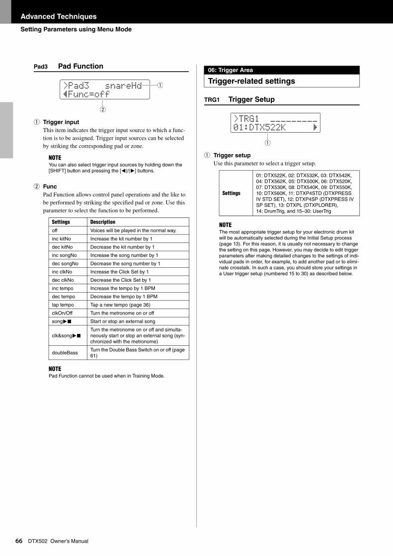
Advanced Techniques
Setting Parameters using Menu Mode
66
DTX502 Owner’s ManualPad3 Pad Function
q Trigger input
This item indicates the trigger input source to which a func-tion is to be assigned. Trigger input sources can be selected by striking the corresponding pad or zone.
w Func
Pad Function allows control panel operations and the like to be performed by striking the specified pad or zone. Use this parameter to select the function to be performed.
TRG1 Trigger Setup
q Trigger setup
Use this parameter to select a trigger setup.NOTEYou can also select trigger input sources by holding down the [SHIFT] button and pressing the [<]/[>] buttons.
Settings Description
off Voices will be played in the normal way.
inc kitNo Increase the kit number by 1
dec kitNo Decrease the kit number by 1
inc songNo Increase the song number by 1
dec songNo Decrease the song number by 1
inc clkNo Increase the Click Set by 1
dec clkNo Decrease the Click Set by 1
inc tempo Increase the tempo by 1 BPM
dec tempo Decrease the tempo by 1 BPM
tap tempo Tap a new tempo (page 36)
clkOn/Off Turn the metronome on or off
song> Start or stop an external song
clk&song>Turn the metronome on or off and simulta-neously start or stop an external song (syn-chronized with the metronome)
doubleBassTurn the Double Bass Switch on or off (page 61)
NOTEPad Function cannot be used when in Training Mode.
>Pad3 snareHd”Func=off
w
q
06: Trigger Area
Trigger-related settings
Settings
01: DTX522K, 02: DTX532K, 03: DTX542K, 04: DTX562K, 05: DTX500K, 06: DTX520K, 07: DTX530K, 08: DTX540K, 09: DTX550K, 10: DTX560K, 11: DTXP4STD (DTXPRESS IV STD SET), 12: DTXP4SP (DTXPRESS IV SP SET), 13: DTXPL (DTXPLORER), 14: DrumTrig, and 15–30: UserTrig
NOTEThe most appropriate trigger setup for your electronic drum kit will be automatically selected during the Initial Setup process (page 13). For this reason, it is usually not necessary to change the setting on this page. However, you may decide to edit trigger parameters after making detailed changes to the settings of indi-vidual pads in order, for example, to add another pad or to elimi-nate crosstalk. In such a case, you should store your settings in a User trigger setup (numbered 15 to 30) as described below.
>tRG1 ¢¢¢¢¢¢¢¢¢01:DtX522K ‚
q
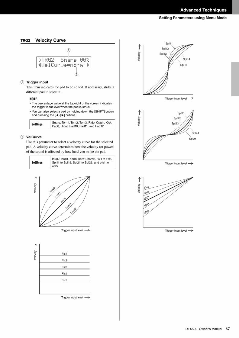
Advanced Techniques
Setting Parameters using Menu Mode
67
DTX502 Owner’s ManualTRG2 Velocity Curve
q Trigger input
This item indicates the pad to be edited. If necessary, strike a different pad to select it.
w VelCurve
Use this parameter to select a velocity curve for the selected pad. A velocity curve determines how the velocity (or power) of the sound is affected by how hard you strike the pad.
NOTE• The percentage value at the top-right of the screen indicates
the trigger input level when the pad is struck.
• You can also select a pad by holding down the [SHIFT] button and pressing the [<]/[>] buttons.
Settings Snare, Tom1, Tom2, Tom3, Ride, Crash, Kick, Pad8, Hihat, Pad10, Pad11, and Pad12
Settingsloud2, loud1, norm, hard1, hard2, Fix1 to Fix5, Spl11 to Spl15, Spl21 to Spl25, and ofs1 to ofs5
>tRG2 Snare 00%”VelCurVe=norm ‚
w
q
loud2
loud1
norm
hard
1
hard
2
Fix1
Fix2
Fix3
Fix4
Fix5
Trigger input level
Vel
ocity
Trigger input level
Vel
ocity
ofs3
ofs4
ofs5
ofs2
ofs1
Spl12
Spl11
Spl13
Spl14
Spl15
Spl22
Spl21
Spl23
Spl24
Spl25
Trigger input level
Vel
ocity
Trigger input level
Vel
ocity
Trigger input level
Vel
ocity
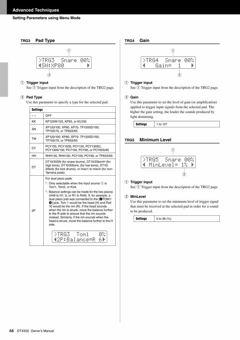
Advanced Techniques
Setting Parameters using Menu Mode
68
DTX502 Owner’s ManualTRG3 Pad Type
q Trigger input
See q Trigger input from the description of the TRG2 page.
w Pad Type
Use this parameter to specify a type for the selected pad.
TRG4 Gain
q Trigger input
See q Trigger input from the description of the TRG2 page.
w Gain
Use this parameter to set the level of gain (or amplification) applied to trigger input signals from the selected pad. The higher the gain setting, the louder the sounds produced by light drumming.
TRG5 Minimum Level
q Trigger input
See q Trigger input from the description of the TRG2 page.
w MinLevel
Use this parameter to set the minimum level of trigger signal that must be received at the selected pad in order for a sound to be produced.
Settings
– – OFF
KK KP125W/125, KP65, or KU100
SNXP120/100, XP80, XP70, TP120SD/100, TP70S/70, or TP65S/65
TMXP120/100, XP80, XP70, TP120SD/100, TP70S/70, or TP65S/65
CYPCY155, PCY150S, PCY135, PCY130SC, PCY130S/130, PCY100, PCY90, or PCY65S/65
HH RHH135, RHH130, PCY100, PCY90, or TP65S/65
DT
DT10/20SN (for snare drums), DT10/20tomH (for high toms), DT10/20tomL (for low toms), DT10/20kick (for kick drums), or misc1 to misc4 (for non-Yamaha pads)
2P
For dual piezo pads
*: Only selectable when the input source q is Tom1, Tom2, or Kick.
*: Balance settings can be made for the two piezos (H49 to H1, 0, or R1 to R49). If, for example, a dual piezo pad was connected to the [wTOM1/!0] jack, Tom 1 would be the head (H) and Pad 10 would be the rim (R). If the head sounds when the rim is struck, move the balance further to the R side to ensure that the rim sounds instead. Similarly, if the rim sounds when the head is struck, move the balance further to the H side.
>tRG3 Snare 00%”SN:XP80 ‚
w
q
>tRG3 tom1 0%”2P:Balance=R 6‚
Settings 1 to 127
Settings 0 to 99 (%)
>tRG4 Snare 00%” Gain= 1 ‚
w
q
>tRG5 Snare 00%” MinLeVel= 1% ‚
w
q
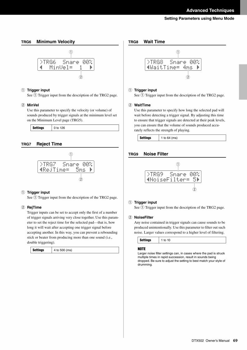
Advanced Techniques
Setting Parameters using Menu Mode
69
DTX502 Owner’s ManualTRG6 Minimum Velocity
q Trigger input
See q Trigger input from the description of the TRG2 page.
w MinVel
Use this parameter to specify the velocity (or volume) of sounds produced by trigger signals at the minimum level set on the Minimum Level page (TRG5).
TRG7 Reject Time
q Trigger input
See q Trigger input from the description of the TRG2 page.
w RejTime
Trigger inputs can be set to accept only the first of a number of trigger signals arriving very close together. Use this param-eter to set the reject time for the selected pad—that is, how long it will wait after accepting one trigger signal before accepting another. In this way, you can prevent a rebounding stick or beater from producing more than one sound (i.e., double triggering).
TRG8 Wait Time
q Trigger input
See q Trigger input from the description of the TRG2 page.
w WaitTime
Use this parameter to specify how long the selected pad will wait before detecting a trigger signal. By adjusting this time to ensure that trigger signals are detected at their peak levels, you can ensure that the volume of sounds produced accu-rately reflects the strength of playing.
TRG9 Noise Filter
q Trigger input
See q Trigger input from the description of the TRG2 page.
w NoiseFilter
Any noise contained in trigger signals can cause sounds to be produced unintentionally. Use this parameter to filter out such noise. Larger values correspond to a higher level of filtering.
Settings 0 to 126
Settings 4 to 500 (ms)
>tRG6 Snare 00%” MinVel= 1 ‚
w
q
>tRG7 Snare 00%”Rejtime= 5ms ‚
w
q
Settings 1 to 64 (ms)
Settings 1 to 10
NOTELarger noise filter settings can, in cases where the pad is struck multiple times in rapid succession, result in sounds being dropped. Be sure to adjust the setting to best match your style of drumming.
>tRG8 Snare 00%”Waittime= 4ms ‚
w
q
>tRG9 Snare 00%”NoiseFilter= 5‚
w
q
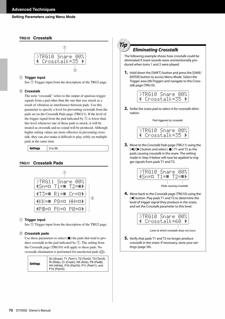
Advanced Techniques
Setting Parameters using Menu Mode
70
DTX502 Owner’s ManualTRG10 Crosstalk
q Trigger input
See q Trigger input from the description of the TRG2 page.
w Crosstalk
The term “crosstalk” refers to the output of spurious trigger signals from a pad other than the one that was struck as a result of vibration or interference between pads. Use this parameter to specify a level for preventing crosstalk from the pads set on the Crosstalk Pads page (TRG11). If the level of the trigger signal from the pad indicated by q is lower than this level whenever one of those pads is struck, it will be treated as crosstalk and no sound will be produced. Although higher setting values are more effective in preventing cross-talk, they can also make it difficult to play softly on multiple pads at the same time.
TRG11 Crosstalk Pads
q Trigger input
See q Trigger input from the description of the TRG2 page.
w Crosstalk pads
Use these parameters to select () the pads that tend to pro-duce crosstalk in the pad indicated by q. The setting from the Crosstalk page (TRG10) will apply to these pads. No crosstalk elimination is performed for unselected pads ().
Settings 0 to 99
Settings
Sn (Snare), T1 (Tom1), T2 (Tom2), T3 (Tom3), Ri (Ride), Cr (Crash), KK (Kick), P8 (Pad8), HH (HiHat), P10 (Pad10), P11 (Pad11), and P12 (Pad12)
>tRG10 Snare 00%” Crosstalk=35 ‚
w
q
”P:=K P;=K P<=K‚
”KK=L P8=K HH=K‚
”t3=L Ri=L Cr=K‚
>tRG11 Snare 00%”Sn=K t1=L t2=L‚
w
q
Eliminating CrosstalkThe following example shows how crosstalk could be eliminated if snare sounds were unintentionally pro-duced when toms 1 and 2 were played.
1. Hold down the [SHIFT] button and press the [SAVE/ENTER] button to access Menu Mode. Select the Trigger area (06:Trigger) and navigate to the Cross-talk page (TRG10).
2. Strike the snare pad to select it for crosstalk elimi-nation.
3. Move to the Crosstalk Pads page (TRG11) using the [<]/[>] button and select ( ) T1 and T2 as the pads causing crosstalk in the snare. The setting made in Step 4 below will now be applied to trig-ger signals from pads T1 and T2.
4. Move back to the Crosstalk page (TRG10) using the [<] button. Play pads T1 and T2 to determine the level of trigger signal they produce in the snare, and set the Crosstalk parameter to this level.
5. Verify that pads T1 and T2 no longer produce crosstalk in the snare. If necessary, store your set-tings (page 56).
>tRG10 Snare 00%” Crosstalk=35 ‚
>tRG10 Snare 00%” Crosstalk=35 ‚
Pad triggered by crosstalk
>tRG10 Snare 00%”Sn=K t1=L t2=L‚
Pads causing crosstalk
>tRG10 Snare 00%” Crosstalk=60 ‚
Level at which crosstalk does not occur
Tip

Advanced Techniques
Setting Parameters using Menu Mode
71
DTX502 Owner’s ManualTRG12 Copy Trigger
On the Copy Trigger page, you can copy all settings for a specific pad into the current trigger setup from another.
1. Navigate to the Copy Trigger page and set both the trigger setup to copy from and the pad to be copied.
2. Move the cursor and set the destination pad (from the current drum trigger).
3. Press the [SAVE/ENTER] button. You will be asked to confirm that you wish to copy the pad.
Press the [SAVE/ENTER] button once again to copy the pad. To cancel the process without copying any data, press the [ ] button.
4. When the pad has been successfully copied, the message “Completed.” will be displayed.
When you copy pad settings using the procedure described
below, the current trigger setup’s settings will be modified
but not stored (i.e., the asterisk (*) will be displayed). To
make the change permanent, be sure to store your settings
(page 56). If you select another kit or turn off the drum mod-
ule without doing so, the trigger setup will revert to its origi-
nal settings.
NOTEWhen the pad name is flashing, you can also select a different one by striking it or by holding down the [SHIFT] button and pressing the [<]/[>] buttons.
NOTEWhen the destination pad is flashing, you can also select a dif-ferent one by striking it or by holding down the [SHIFT] button and pressing the [<]/[>] buttons.
>tRG12 CopyPad” 1:Snare≥Snare
NOTICE
>tRG12 CopyPad” 1:Snare≥Snare
Number of trigger setup to copy from: Pad to be copied
>tRG12 CopyPad” 2:tom1≥tom2
Destination pad
CAUTIONWhenever a pad is copied, all of the destination pad’s
settings will be overwritten with those of the copied
pad. Before proceeding, therefore, you should ensure
that the destination pad contains no irreplaceable set-
tings.
>tRG12 CopyPad Are you sure?
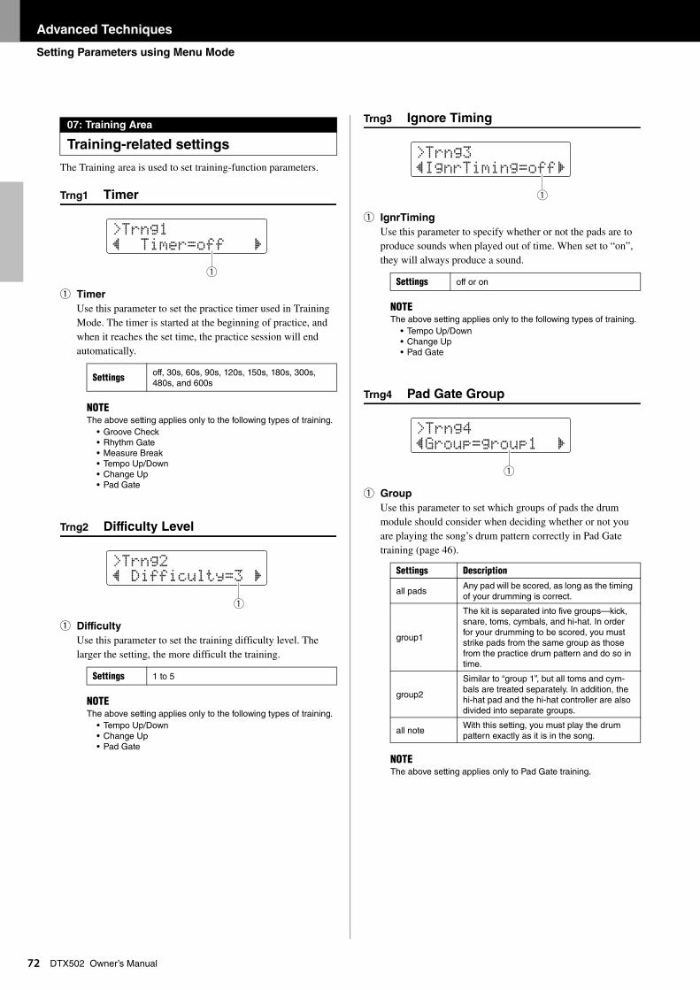
Advanced Techniques
Setting Parameters using Menu Mode
72
DTX502 Owner’s ManualThe Training area is used to set training-function parameters.
Trng1 Timer
q Timer
Use this parameter to set the practice timer used in Training Mode. The timer is started at the beginning of practice, and when it reaches the set time, the practice session will end automatically.
Trng2 Difficulty Level
q Difficulty
Use this parameter to set the training difficulty level. The larger the setting, the more difficult the training.
Trng3 Ignore Timing
q IgnrTiming
Use this parameter to specify whether or not the pads are to produce sounds when played out of time. When set to “on”, they will always produce a sound.
Trng4 Pad Gate Group
q Group
Use this parameter to set which groups of pads the drum module should consider when deciding whether or not you are playing the song’s drum pattern correctly in Pad Gate training (page 46).
07: Training Area
Training-related settings
Settings off, 30s, 60s, 90s, 120s, 150s, 180s, 300s, 480s, and 600s
NOTEThe above setting applies only to the following types of training.
• Groove Check • Rhythm Gate• Measure Break• Tempo Up/Down• Change Up• Pad Gate
Settings 1 to 5
NOTEThe above setting applies only to the following types of training.
• Tempo Up/Down• Change Up• Pad Gate
>trng1” timer=off ‚
q
>trng2” Difficulty=3 ‚
q
Settings off or on
NOTEThe above setting applies only to the following types of training.
• Tempo Up/Down• Change Up• Pad Gate
Settings Description
all padsAny pad will be scored, as long as the timing of your drumming is correct.
group1
The kit is separated into five groups—kick, snare, toms, cymbals, and hi-hat. In order for your drumming to be scored, you must strike pads from the same group as those from the practice drum pattern and do so in time.
group2
Similar to “group 1”, but all toms and cym-bals are treated separately. In addition, the hi-hat pad and the hi-hat controller are also divided into separate groups.
all noteWith this setting, you must play the drum pattern exactly as it is in the song.
NOTEThe above setting applies only to Pad Gate training.
>trng3”Ignrtiming=off‚
q
>trng4”Group=group1 ‚
q
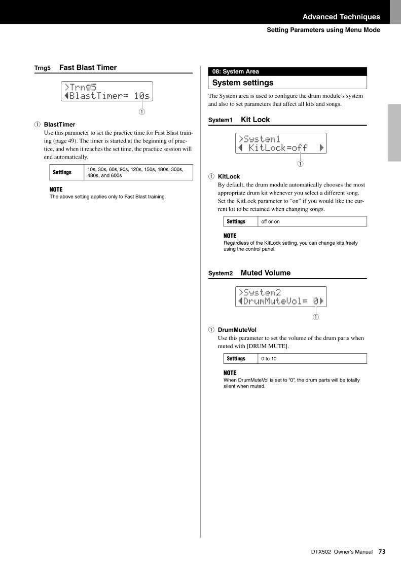
Advanced Techniques
Setting Parameters using Menu Mode
73
DTX502 Owner’s ManualTrng5 Fast Blast Timer
q BlastTimer
Use this parameter to set the practice time for Fast Blast train-ing (page 49). The timer is started at the beginning of prac-tice, and when it reaches the set time, the practice session will end automatically.
The System area is used to configure the drum module’s system and also to set parameters that affect all kits and songs.
System1 Kit Lock
q KitLock
By default, the drum module automatically chooses the most appropriate drum kit whenever you select a different song. Set the KitLock parameter to “on” if you would like the cur-rent kit to be retained when changing songs.
System2 Muted Volume
q DrumMuteVol
Use this parameter to set the volume of the drum parts when muted with [DRUM MUTE].
Settings 10s, 30s, 60s, 90s, 120s, 150s, 180s, 300s, 480s, and 600s
NOTEThe above setting applies only to Fast Blast training.
>trng5”Blasttimer= 10s
q
08: System Area
System settings
Settings off or on
NOTERegardless of the KitLock setting, you can change kits freely using the control panel.
Settings 0 to 10
NOTEWhen DrumMuteVol is set to “0”, the drum parts will be totally silent when muted.
>System1” KitLock=off ‚
q
>System2”DrumMuteVol= 0‚
q
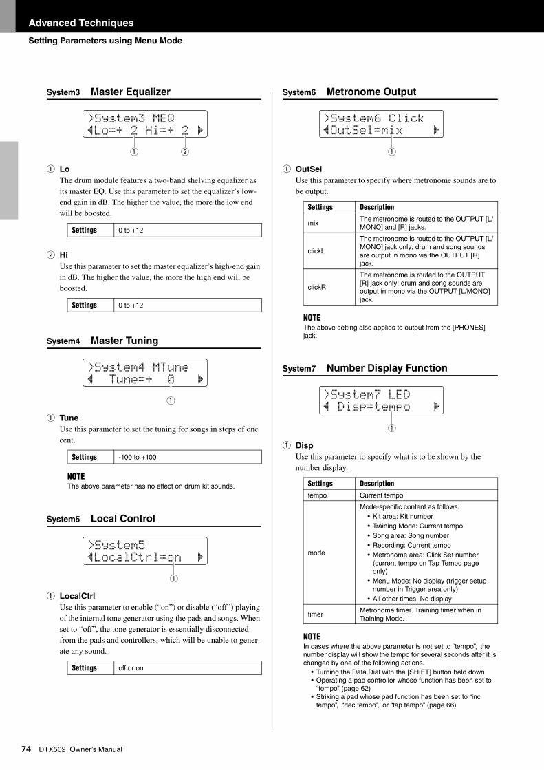
Advanced Techniques
Setting Parameters using Menu Mode
74
DTX502 Owner’s ManualSystem3 Master Equalizer
q Lo
The drum module features a two-band shelving equalizer as its master EQ. Use this parameter to set the equalizer’s low-end gain in dB. The higher the value, the more the low end will be boosted.
w Hi
Use this parameter to set the master equalizer’s high-end gain in dB. The higher the value, the more the high end will be boosted.
System4 Master Tuning
q Tune
Use this parameter to set the tuning for songs in steps of one cent.
System5 Local Control
q LocalCtrl
Use this parameter to enable (“on”) or disable (“off”) playing of the internal tone generator using the pads and songs. When set to “off”, the tone generator is essentially disconnected from the pads and controllers, which will be unable to gener-ate any sound.
System6 Metronome Output
q OutSel
Use this parameter to specify where metronome sounds are to be output.
System7 Number Display Function
q Disp
Use this parameter to specify what is to be shown by the number display.
Settings 0 to +12
Settings 0 to +12
Settings -100 to +100
NOTEThe above parameter has no effect on drum kit sounds.
Settings off or on
>System3 MEQ”Lo=+ 2 Hi=+ 2 ‚
wq
>System4 Mtune” tune=+ 0 ‚
q
>System5”LocalCtrl=on ‚
q
Settings Description
mixThe metronome is routed to the OUTPUT [L/MONO] and [R] jacks.
clickL
The metronome is routed to the OUTPUT [L/MONO] jack only; drum and song sounds are output in mono via the OUTPUT [R] jack.
clickR
The metronome is routed to the OUTPUT [R] jack only; drum and song sounds are output in mono via the OUTPUT [L/MONO] jack.
NOTEThe above setting also applies to output from the [PHONES] jack.
Settings Description
tempo Current tempo
mode
Mode-specific content as follows.• Kit area: Kit number• Training Mode: Current tempo• Song area: Song number• Recording: Current tempo• Metronome area: Click Set number
(current tempo on Tap Tempo page only)
• Menu Mode: No display (trigger setup number in Trigger area only)
• All other times: No display
timerMetronome timer. Training timer when in Training Mode.
NOTEIn cases where the above parameter is not set to “tempo”, the number display will show the tempo for several seconds after it is changed by one of the following actions.
• Turning the Data Dial with the [SHIFT] button held down• Operating a pad controller whose function has been set to
“tempo” (page 62)• Striking a pad whose pad function has been set to “inc
tempo”, “dec tempo”, or “tap tempo” (page 66)
>System6 Click”OutSel=mix ‚
q
>System7 LED” Disp=tempo ‚
q
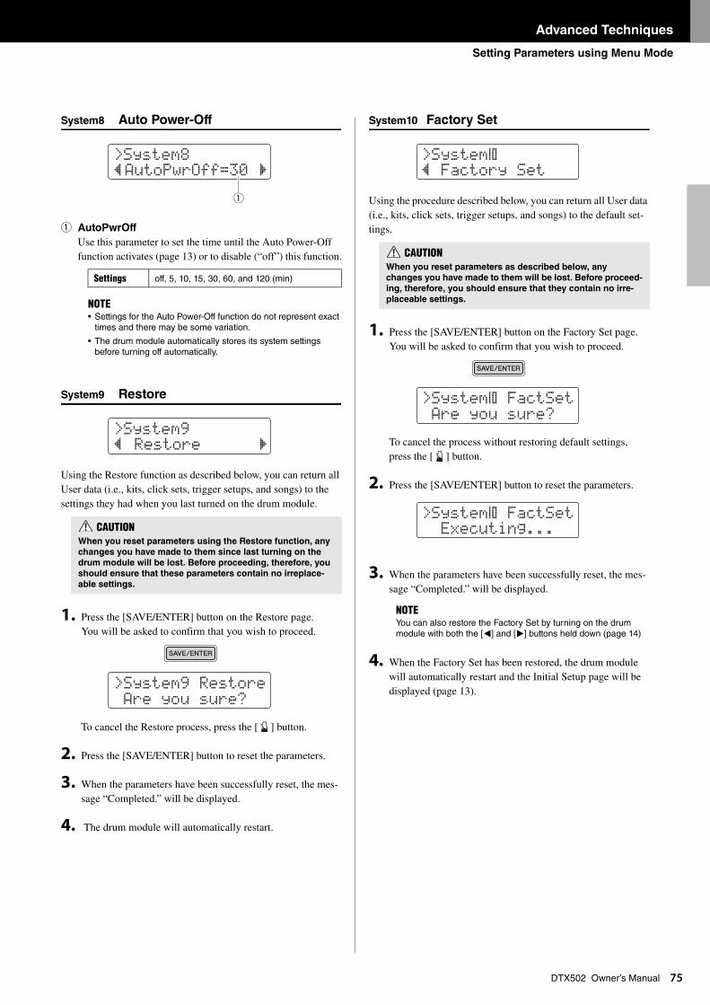
Advanced Techniques
Setting Parameters using Menu Mode
75
DTX502 Owner’s ManualSystem8 Auto Power-Off
q AutoPwrOff
Use this parameter to set the time until the Auto Power-Off function activates (page 13) or to disable (“off”) this function.
System9 Restore
Using the Restore function as described below, you can return all User data (i.e., kits, click sets, trigger setups, and songs) to the settings they had when you last turned on the drum module.
1. Press the [SAVE/ENTER] button on the Restore page. You will be asked to confirm that you wish to proceed.
To cancel the Restore process, press the [ ] button.
2. Press the [SAVE/ENTER] button to reset the parameters.
3. When the parameters have been successfully reset, the mes-sage “Completed.” will be displayed.
4. The drum module will automatically restart.
System10 Factory Set
Using the procedure described below, you can return all User data (i.e., kits, click sets, trigger setups, and songs) to the default set-tings.
1. Press the [SAVE/ENTER] button on the Factory Set page. You will be asked to confirm that you wish to proceed.
To cancel the process without restoring default settings, press the [ ] button.
2. Press the [SAVE/ENTER] button to reset the parameters.
3. When the parameters have been successfully reset, the mes-sage “Completed.” will be displayed.
4. When the Factory Set has been restored, the drum module will automatically restart and the Initial Setup page will be displayed (page 13).
Settings off, 5, 10, 15, 30, 60, and 120 (min)
NOTE• Settings for the Auto Power-Off function do not represent exact
times and there may be some variation.
• The drum module automatically stores its system settings before turning off automatically.
CAUTIONWhen you reset parameters using the Restore function, any
changes you have made to them since last turning on the
drum module will be lost. Before proceeding, therefore, you
should ensure that these parameters contain no irreplace-
able settings.
>System8” AutoPwrOff=30 ‚
q
>System9” Restore ‚
>System9 Restore Are you sure?
CAUTIONWhen you reset parameters as described below, any
changes you have made to them will be lost. Before proceed-
ing, therefore, you should ensure that they contain no irre-
placeable settings.
NOTEYou can also restore the Factory Set by turning on the drum module with both the [<] and [>] buttons held down (page 14)
>System:” Factory Set
>System: FactSet Are you sure?
>System: FactSet Executing...
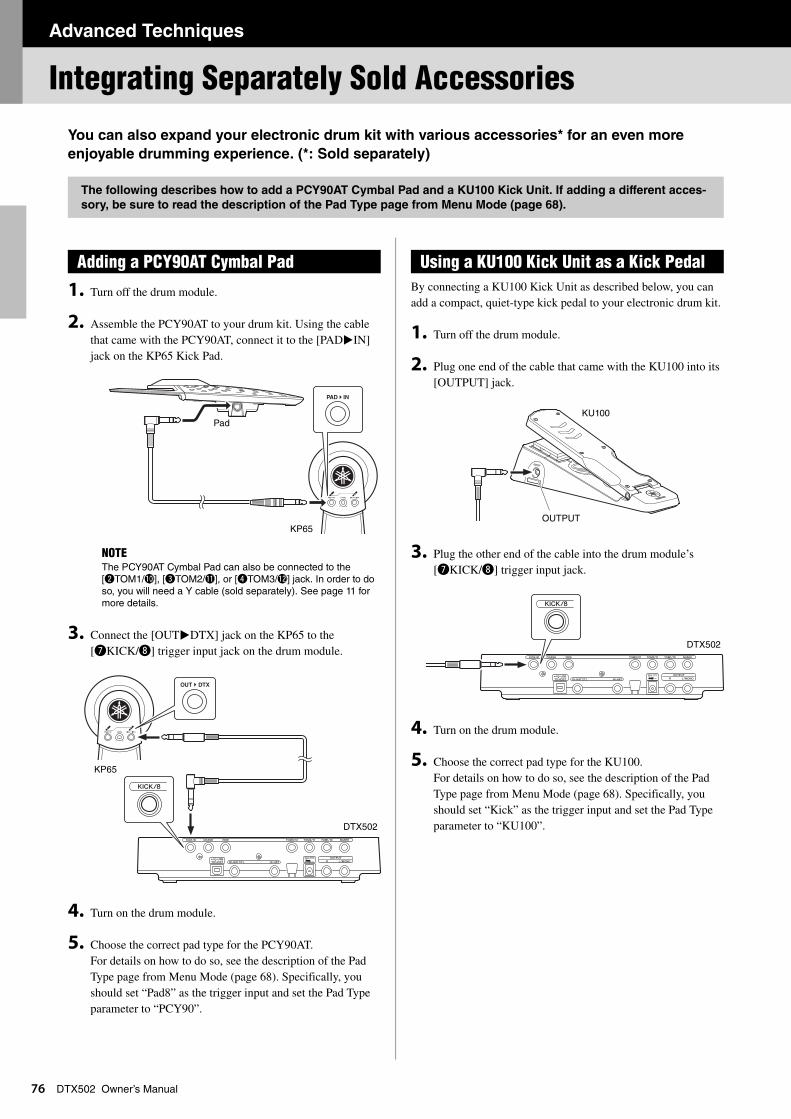
Advanced Techniques
7
Integrating Separately Sold Accessories
6
DTX502 Owner’s ManualYou can also expand your electronic drum kit with various accessories* for an even more
enjoyable drumming experience. (*: Sold separately)
1. Turn off the drum module.
2. Assemble the PCY90AT to your drum kit. Using the cable that came with the PCY90AT, connect it to the [PAD>IN] jack on the KP65 Kick Pad.
3. Connect the [OUT>DTX] jack on the KP65 to the [uKICK/i] trigger input jack on the drum module.
4. Turn on the drum module.
5. Choose the correct pad type for the PCY90AT. For details on how to do so, see the description of the Pad Type page from Menu Mode (page 68). Specifically, you should set “Pad8” as the trigger input and set the Pad Type parameter to “PCY90”.
By connecting a KU100 Kick Unit as described below, you can add a compact, quiet-type kick pedal to your electronic drum kit.
1. Turn off the drum module.
2. Plug one end of the cable that came with the KU100 into its [OUTPUT] jack.
3. Plug the other end of the cable into the drum module’s [uKICK/i] trigger input jack.
4. Turn on the drum module.
5. Choose the correct pad type for the KU100.For details on how to do so, see the description of the Pad Type page from Menu Mode (page 68). Specifically, you should set “Kick” as the trigger input and set the Pad Type parameter to “KU100”.
The following describes how to add a PCY90AT Cymbal Pad and a KU100 Kick Unit. If adding a different acces-
sory, be sure to read the description of the Pad Type page from Menu Mode (page 68).
Adding a PCY90AT Cymbal Pad
NOTEThe PCY90AT Cymbal Pad can also be connected to the [wTOM1/!0], [eTOM2/!1], or [rTOM3/!2] jack. In order to do so, you will need a Y cable (sold separately). See page 11 for more details.
Pad
KP65
DTX502
KP65
Using a KU100 Kick Unit as a Kick Pedal
KU100
OUTPUT
DTX502
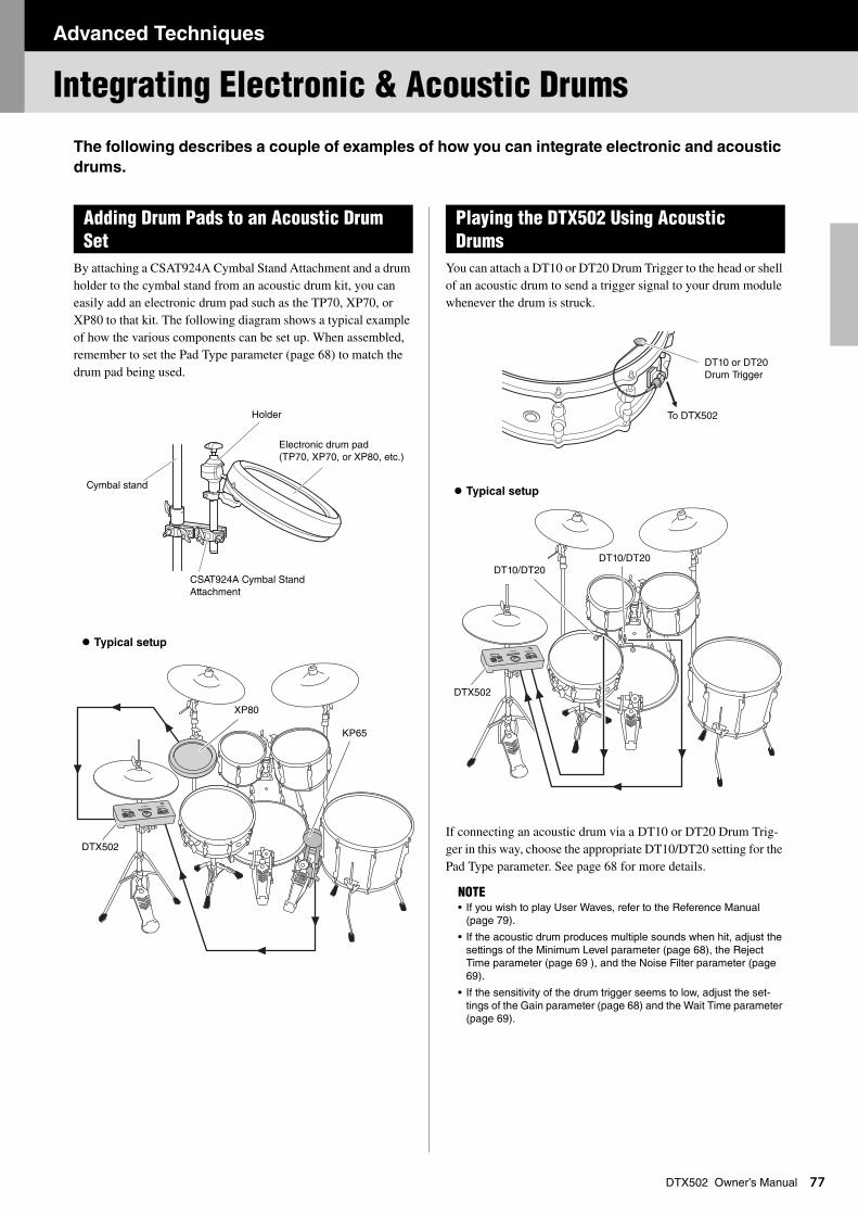
Advanced Techniques
Integrating Electronic & Acoustic Drums
77
DTX502 Owner’s ManualThe following describes a couple of examples of how you can integrate electronic and acoustic
drums.
By attaching a CSAT924A Cymbal Stand Attachment and a drum holder to the cymbal stand from an acoustic drum kit, you can easily add an electronic drum pad such as the TP70, XP70, or XP80 to that kit. The following diagram shows a typical example of how the various components can be set up. When assembled, remember to set the Pad Type parameter (page 68) to match the drum pad being used.
You can attach a DT10 or DT20 Drum Trigger to the head or shell of an acoustic drum to send a trigger signal to your drum module whenever the drum is struck.
If connecting an acoustic drum via a DT10 or DT20 Drum Trig-ger in this way, choose the appropriate DT10/DT20 setting for the Pad Type parameter. See page 68 for more details.
Adding Drum Pads to an Acoustic Drum Set
Typical setup
Holder
Cymbal stand
Electronic drum pad (TP70, XP70, or XP80, etc.)
CSAT924A Cymbal Stand Attachment
XP80
DTX502
KP65
Playing the DTX502 Using Acoustic Drums
NOTE• If you wish to play User Waves, refer to the Reference Manual
(page 79).
• If the acoustic drum produces multiple sounds when hit, adjust the settings of the Minimum Level parameter (page 68), the Reject Time parameter (page 69 ), and the Noise Filter parameter (page 69).
• If the sensitivity of the drum trigger seems to low, adjust the set-tings of the Gain parameter (page 68) and the Wait Time parameter (page 69).
Typical setup
DT10 or DT20 Drum Trigger
To DTX502
DT10/DT20DT10/DT20
DTX502
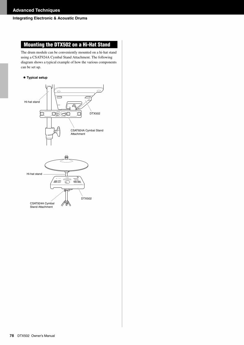
Advanced Techniques
Integrating Electronic & Acoustic Drums
78
DTX502 Owner’s ManualThe drum module can be conveniently mounted on a hi-hat stand using a CSAT924A Cymbal Stand Attachment. The following diagram shows a typical example of how the various components can be set up.
Mounting the DTX502 on a Hi-Hat Stand
Typical setup
Hi-hat stand
DTX502
CSAT924A Cymbal Stand Attachment
DTX502
Hi-hat stand
CSAT924A Cymbal Stand Attachment
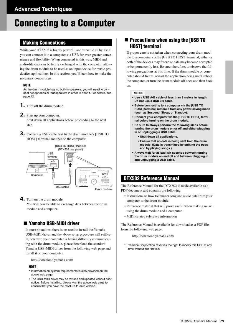
Advanced Techniques
Connecting to a Computer
79
DTX502 Owner’s ManualWhile your DTX502 is highly powerful and versatile all by itself, you can connect it to a computer via USB for even greater conve-nience and flexibility. When connected in this way, MIDI and audio-file data can be freely exchanged with the computer, allow-ing the drum module to be used as an input device for music pro-duction applications. In this section, you’ll learn how to make the necessary connections.
1. Turn off the drum module.
2. Start up your computer. Shut down all applications before proceeding to the next step.
3. Connect a USB cable first to the drum module’s [USB TO HOST] terminal and then to the computer.
4. Turn on the drum module. You will now be able to exchange data between the drum module and computer.
Yamaha USB-MIDI driverIn most situations, there is no need to install the Yamaha USB-MIDI driver and the above setup procedure will suffice. If, however, your computer is having difficulty communicat-ing with the drum module, please download the standard Yamaha USB-MIDI driver from the following web page and install it on your computer.
http://download.yamaha.com/
Precautions when using the [USB TO HOST] terminal
If proper care is not taken when connecting your drum mod-ule to a computer via the [USB TO HOST] terminal, either or both of the devices may freeze or data may become corrupted or be permanently lost. Be sure, therefore, to observe the fol-lowing precautions at this time. If the drum module or com-puter should freeze, restart the application being used, reboot the computer, or turn the drum module off once and then back on.
The Reference Manual for the DTX502 is made available as a PDF document and contains the following.
• Instructions on how to transfer song and audio data from your computer to the drum module.
• Reference material that will prove useful when making music using the drum module and a computer
• MIDI-related reference information
The Reference Manual is available for download as a PDF file from the following web page.
http://download.yamaha.com/
*: Yamaha Corporation reserves the right to modify this URL at any time without prior notice.
Making Connections
NOTEAs the drum module has no built-in speakers, you will need to con-nect headphones or loudspeakers in order to hear it. For details, see page 12.
NOTE• Information on system requirements is also provided on the
above web page.
• The USB-MIDI driver may be revised and updated without prior notice. Before installing, please visit the above web page to confirm that you have the most up-to-date version.
[USB TO HOST] terminal (DTX502 rear panel)
USB terminal
Computer
Drum moduleUSB cable
• Use a USB A-B cable of less than 3 meters in length.
Do not use a USB 3.0 cable.
• Before connecting to a computer via the [USB TO
HOST] terminal, restore it from any power-saving mode
(such as Suspend, Sleep, or Standby).
• Connect your computer via the [USB TO HOST] termi-
nal before turning on the drum module.
• Be sure to always perform the following steps before
turning the drum module on or off and either plugging
in or unplugging a USB cable.
• Shut down all applications.
• Ensure that no data is being sent from the drum
module. (Data is transmitted by striking the pads
and by playing songs.)
• Always wait for at least six seconds between turning
the drum module on and off and between plugging in
and unplugging a USB cable.
DTX502 Reference Manual
NOTICE
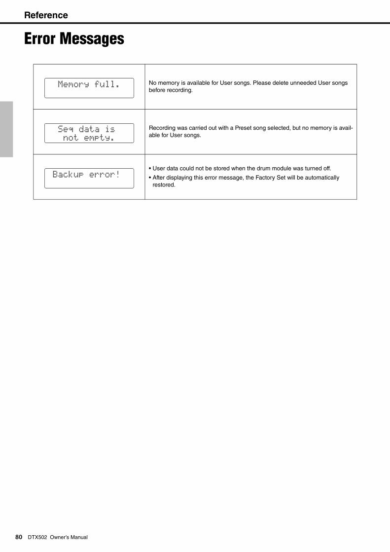
Reference
Reference
8
Error Messages
0
DTX502 Owner’s ManualNo memory is available for User songs. Please delete unneeded User songs before recording.
Recording was carried out with a Preset song selected, but no memory is avail-able for User songs.
• User data could not be stored when the drum module was turned off.
• After displaying this error message, the Factory Set will be automatically restored.
Memory full.
Seq data is not empty.
Backup error!
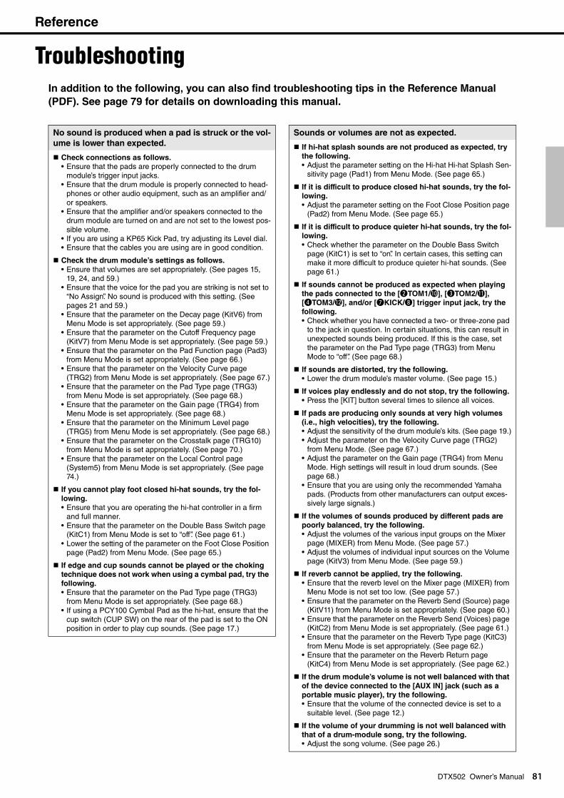
Reference
Troubleshooting
In addition to the following, you can also find troubleshooting tips in the Reference Manual(PDF). See page 79 for details on downloading this manual.
No sound is produced when a pad is struck or the vol-
ume is lower than expected.
Check connections as follows.
• Ensure that the pads are properly connected to the drum module’s trigger input jacks.
• Ensure that the drum module is properly connected to head-phones or other audio equipment, such as an amplifier and/or speakers.
• Ensure that the amplifier and/or speakers connected to the drum module are turned on and are not set to the lowest pos-sible volume.
• If you are using a KP65 Kick Pad, try adjusting its Level dial. • Ensure that the cables you are using are in good condition.
Check the drum module’s settings as follows.
• Ensure that volumes are set appropriately. (See pages 15, 19, 24, and 59.)
• Ensure that the voice for the pad you are striking is not set to “No Assign”. No sound is produced with this setting. (See pages 21 and 59.)
• Ensure that the parameter on the Decay page (KitV6) from Menu Mode is set appropriately. (See page 59.)
• Ensure that the parameter on the Cutoff Frequency page (KitV7) from Menu Mode is set appropriately. (See page 59.)
• Ensure that the parameter on the Pad Function page (Pad3) from Menu Mode is set appropriately. (See page 66.)
• Ensure that the parameter on the Velocity Curve page (TRG2) from Menu Mode is set appropriately. (See page 67.)
• Ensure that the parameter on the Pad Type page (TRG3) from Menu Mode is set appropriately. (See page 68.)
• Ensure that the parameter on the Gain page (TRG4) from Menu Mode is set appropriately. (See page 68.)
• Ensure that the parameter on the Minimum Level page (TRG5) from Menu Mode is set appropriately. (See page 68.)
• Ensure that the parameter on the Crosstalk page (TRG10) from Menu Mode is set appropriately. (See page 70.)
• Ensure that the parameter on the Local Control page (System5) from Menu Mode is set appropriately. (See page 74.)
If you cannot play foot closed hi-hat sounds, try the fol-
lowing.
• Ensure that you are operating the hi-hat controller in a firm and full manner.
• Ensure that the parameter on the Double Bass Switch page (KitC1) from Menu Mode is set to “off”. (See page 61.)
• Lower the setting of the parameter on the Foot Close Position page (Pad2) from Menu Mode. (See page 65.)
If edge and cup sounds cannot be played or the choking
technique does not work when using a cymbal pad, try the
following.
• Ensure that the parameter on the Pad Type page (TRG3) from Menu Mode is set appropriately. (See page 68.)
• If using a PCY100 Cymbal Pad as the hi-hat, ensure that the cup switch (CUP SW) on the rear of the pad is set to the ON position in order to play cup sounds. (See page 17.)
81
DTX502 Owner’s ManualSounds or volumes are not as expected.
If hi-hat splash sounds are not produced as expected, try
the following.
• Adjust the parameter setting on the Hi-hat Hi-hat Splash Sen-sitivity page (Pad1) from Menu Mode. (See page 65.)
If it is difficult to produce closed hi-hat sounds, try the fol-
lowing.
• Adjust the parameter setting on the Foot Close Position page (Pad2) from Menu Mode. (See page 65.)
If it is difficult to produce quieter hi-hat sounds, try the fol-
lowing.
• Check whether the parameter on the Double Bass Switch page (KitC1) is set to “on”. In certain cases, this setting can make it more difficult to produce quieter hi-hat sounds. (See page 61.)
If sounds cannot be produced as expected when playing
the pads connected to the [wTOM1/!0], [eTOM2/!1], [rTOM3/!2], and/or [uKICK/i] trigger input jack, try the
following.
• Check whether you have connected a two- or three-zone pad to the jack in question. In certain situations, this can result in unexpected sounds being produced. If this is the case, set the parameter on the Pad Type page (TRG3) from Menu Mode to “off”. (See page 68.)
If sounds are distorted, try the following.
• Lower the drum module’s master volume. (See page 15.)
If voices play endlessly and do not stop, try the following.
• Press the [KIT] button several times to silence all voices.
If pads are producing only sounds at very high volumes
(i.e., high velocities), try the following.
• Adjust the sensitivity of the drum module’s kits. (See page 19.)• Adjust the parameter on the Velocity Curve page (TRG2)
from Menu Mode. (See page 67.)• Adjust the parameter on the Gain page (TRG4) from Menu
Mode. High settings will result in loud drum sounds. (See page 68.)
• Ensure that you are using only the recommended Yamaha pads. (Products from other manufacturers can output exces-sively large signals.)
If the volumes of sounds produced by different pads are
poorly balanced, try the following.
• Adjust the volumes of the various input groups on the Mixer page (MIXER) from Menu Mode. (See page 57.)
• Adjust the volumes of individual input sources on the Volume page (KitV3) from Menu Mode. (See page 59.)
If reverb cannot be applied, try the following.
• Ensure that the reverb level on the Mixer page (MIXER) from Menu Mode is not set too low. (See page 57.)
• Ensure that the parameter on the Reverb Send (Source) page (KitV11) from Menu Mode is set appropriately. (See page 60.)
• Ensure that the parameter on the Reverb Send (Voices) page (KitC2) from Menu Mode is set appropriately. (See page 61.)
• Ensure that the parameter on the Reverb Type page (KitC3) from Menu Mode is set appropriately. (See page 62.)
• Ensure that the parameter on the Reverb Return page (KitC4) from Menu Mode is set appropriately. (See page 62.)
If the drum module’s volume is not well balanced with that
of the device connected to the [AUX IN] jack (such as a
portable music player), try the following.
• Ensure that the volume of the connected device is set to a suitable level. (See page 12.)
If the volume of your drumming is not well balanced with
that of a drum-module song, try the following.
• Adjust the song volume. (See page 26.)
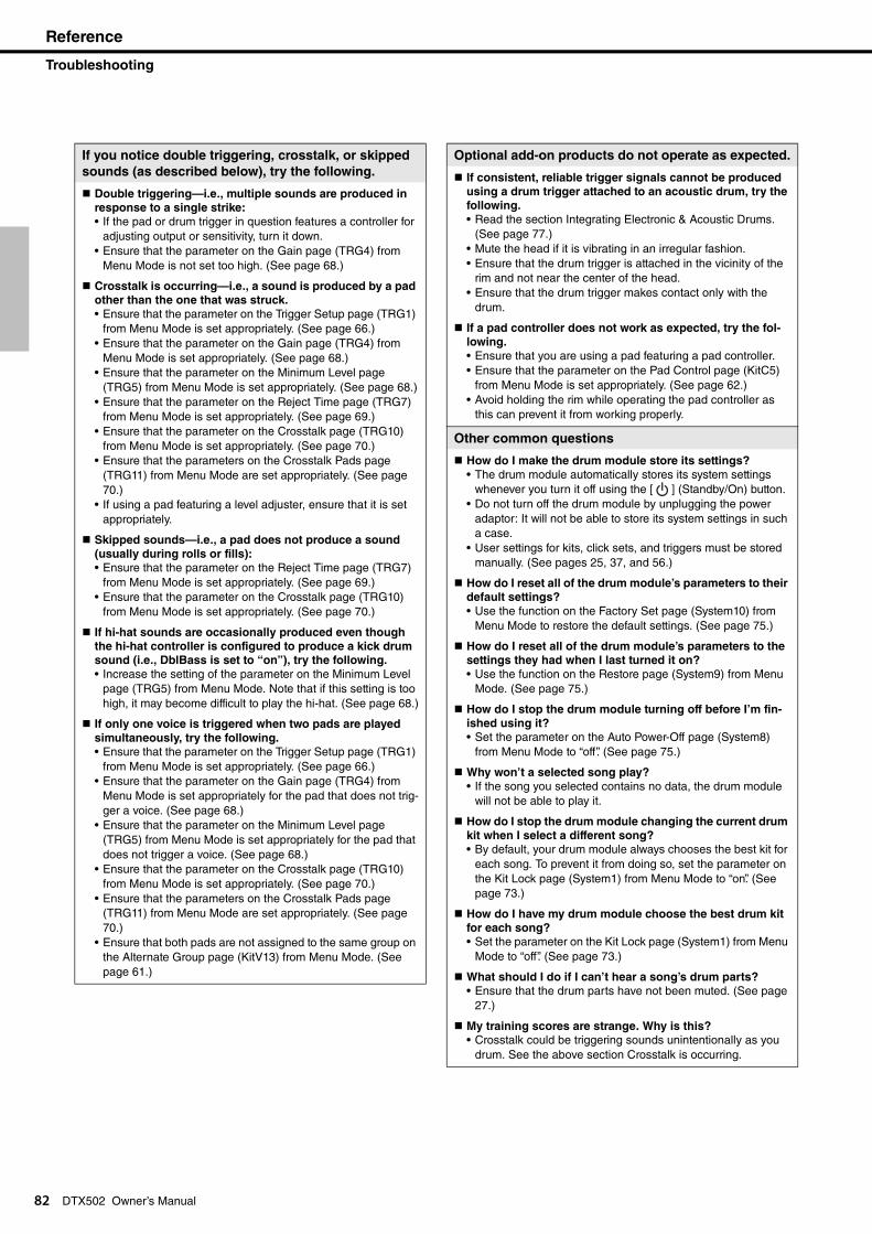
Reference
Troubleshooting
82
If you notice double triggering, crosstalk, or skipped
sounds (as described below), try the following.
Double triggering—i.e., multiple sounds are produced in
response to a single strike:
• If the pad or drum trigger in question features a controller for adjusting output or sensitivity, turn it down.
• Ensure that the parameter on the Gain page (TRG4) from Menu Mode is not set too high. (See page 68.)
Crosstalk is occurring—i.e., a sound is produced by a pad
other than the one that was struck.
• Ensure that the parameter on the Trigger Setup page (TRG1) from Menu Mode is set appropriately. (See page 66.)
• Ensure that the parameter on the Gain page (TRG4) from Menu Mode is set appropriately. (See page 68.)
• Ensure that the parameter on the Minimum Level page (TRG5) from Menu Mode is set appropriately. (See page 68.)
• Ensure that the parameter on the Reject Time page (TRG7) from Menu Mode is set appropriately. (See page 69.)
• Ensure that the parameter on the Crosstalk page (TRG10) from Menu Mode is set appropriately. (See page 70.)
• Ensure that the parameters on the Crosstalk Pads page (TRG11) from Menu Mode are set appropriately. (See page 70.)
• If using a pad featuring a level adjuster, ensure that it is set appropriately.
Skipped sounds—i.e., a pad does not produce a sound
(usually during rolls or fills):
• Ensure that the parameter on the Reject Time page (TRG7) from Menu Mode is set appropriately. (See page 69.)
• Ensure that the parameter on the Crosstalk page (TRG10) from Menu Mode is set appropriately. (See page 70.)
If hi-hat sounds are occasionally produced even though
the hi-hat controller is configured to produce a kick drum
sound (i.e., DblBass is set to “on”), try the following.
• Increase the setting of the parameter on the Minimum Level page (TRG5) from Menu Mode. Note that if this setting is too high, it may become difficult to play the hi-hat. (See page 68.)
If only one voice is triggered when two pads are played
simultaneously, try the following.
• Ensure that the parameter on the Trigger Setup page (TRG1) from Menu Mode is set appropriately. (See page 66.)
• Ensure that the parameter on the Gain page (TRG4) from Menu Mode is set appropriately for the pad that does not trig-ger a voice. (See page 68.)
• Ensure that the parameter on the Minimum Level page (TRG5) from Menu Mode is set appropriately for the pad that does not trigger a voice. (See page 68.)
• Ensure that the parameter on the Crosstalk page (TRG10) from Menu Mode is set appropriately. (See page 70.)
• Ensure that the parameters on the Crosstalk Pads page (TRG11) from Menu Mode are set appropriately. (See page 70.)
• Ensure that both pads are not assigned to the same group on the Alternate Group page (KitV13) from Menu Mode. (See page 61.)
DTX502 Owner’s Manual
Optional add-on products do not operate as expected.
If consistent, reliable trigger signals cannot be produced
using a drum trigger attached to an acoustic drum, try the
following.
• Read the section Integrating Electronic & Acoustic Drums. (See page 77.)
• Mute the head if it is vibrating in an irregular fashion. • Ensure that the drum trigger is attached in the vicinity of the
rim and not near the center of the head. • Ensure that the drum trigger makes contact only with the
drum.
If a pad controller does not work as expected, try the fol-
lowing.
• Ensure that you are using a pad featuring a pad controller. • Ensure that the parameter on the Pad Control page (KitC5)
from Menu Mode is set appropriately. (See page 62.)• Avoid holding the rim while operating the pad controller as
this can prevent it from working properly.
Other common questions
How do I make the drum module store its settings?
• The drum module automatically stores its system settings whenever you turn it off using the [ ] (Standby/On) button.
• Do not turn off the drum module by unplugging the power adaptor: It will not be able to store its system settings in such a case.
• User settings for kits, click sets, and triggers must be stored manually. (See pages 25, 37, and 56.)
How do I reset all of the drum module’s parameters to their
default settings?
• Use the function on the Factory Set page (System10) from Menu Mode to restore the default settings. (See page 75.)
How do I reset all of the drum module’s parameters to the
settings they had when I last turned it on?
• Use the function on the Restore page (System9) from Menu Mode. (See page 75.)
How do I stop the drum module turning off before I’m fin-
ished using it?
• Set the parameter on the Auto Power-Off page (System8) from Menu Mode to “off”. (See page 75.)
Why won’t a selected song play?
• If the song you selected contains no data, the drum module will not be able to play it.
How do I stop the drum module changing the current drum
kit when I select a different song?
• By default, your drum module always chooses the best kit for each song. To prevent it from doing so, set the parameter on the Kit Lock page (System1) from Menu Mode to “on”. (See page 73.)
How do I have my drum module choose the best drum kit
for each song?
• Set the parameter on the Kit Lock page (System1) from Menu Mode to “off”. (See page 73.)
What should I do if I can’t hear a song’s drum parts?
• Ensure that the drum parts have not been muted. (See page 27.)
My training scores are strange. Why is this?
• Crosstalk could be triggering sounds unintentionally as you drum. See the above section Crosstalk is occurring.
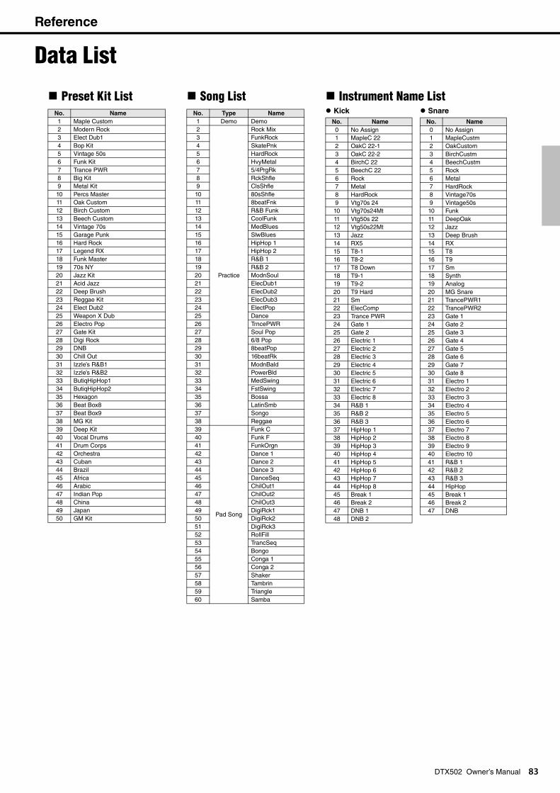
Reference
Data List
DTX502 Owner’s Manual 83
Preset Kit ListNo. Name
1 Maple Custom2 Modern Rock3 Elect Dub14 Bop Kit5 Vintage 50s6 Funk Kit7 Trance PWR8 Big Kit9 Metal Kit10 Percs Master11 Oak Custom12 Birch Custom13 Beech Custom14 Vintage 70s15 Garage Punk16 Hard Rock17 Legend RX18 Funk Master19 70s NY20 Jazz Kit21 Acid Jazz22 Deep Brush23 Reggae Kit24 Elect Dub225 Weapon X Dub26 Electro Pop27 Gate Kit28 Digi Rock29 DNB30 Chill Out31 Izzle’s R&B132 Izzle’s R&B233 ButiqHipHop134 ButiqHipHop235 Hexagon36 Beat Box837 Beat Box938 MG Kit39 Deep Kit40 Vocal Drums41 Drum Corps42 Orchestra43 Cuban44 Brazil45 Africa46 Arabic47 Indian Pop48 China49 Japan50 GM Kit
Song ListNo. Type Name
1 Demo Demo2
Practice
Rock Mix3 FunkRock4 SkatePnk5 HardRock6 HvyMetal7 5/4PrgRk8 RckShfle9 ClsShfle10 80sShfle11 8beatFnk12 R&B Funk13 CoolFunk14 MedBlues15 SlwBlues16 HipHop 117 HipHop 218 R&B 119 R&B 220 ModnSoul21 ElecDub122 ElecDub223 ElecDub324 ElectPop25 Dance26 TrncePWR27 Soul Pop28 6/8 Pop29 8beatPop30 16beatRk31 ModnBald32 PowerBld33 MedSwing34 FstSwing35 Bossa36 LatinSmb37 Songo38 Reggae39
Pad Song
Funk C40 Funk F41 FunkOrgn42 Dance 143 Dance 244 Dance 345 DanceSeq46 ChilOut147 ChilOut248 ChilOut349 DigiRck150 DigiRck251 DigiRck352 RollFill53 TrancSeq54 Bongo55 Conga 156 Conga 257 Shaker58 Tambrin 59 Triangle60 Samba
Instrument Name List Kick Snare
No. Name
0 No Assign1 MapleC 222 OakC 22-13 OakC 22-24 BirchC 225 BeechC 226 Rock7 Metal8 HardRock9 Vtg70s 2410 Vtg70s24Mt11 Vtg50s 2212 Vtg50s22Mt13 Jazz14 RX515 T8-116 T8-217 T8 Down18 T9-119 T9-220 T9 Hard21 Sm22 ElecComp23 Trance PWR24 Gate 125 Gate 226 Electric 127 Electric 228 Electric 329 Electric 430 Electric 531 Electric 632 Electric 733 Electric 834 R&B 135 R&B 236 R&B 337 HipHop 138 HipHop 239 HipHop 340 HipHop 441 HipHop 542 HipHop 643 HipHop 744 HipHop 845 Break 146 Break 247 DNB 148 DNB 2
No. Name
0 No Assign1 MapleCustm2 OakCustom3 BirchCustm4 BeechCustm5 Rock6 Metal7 HardRock8 Vintage70s9 Vintage50s10 Funk11 DeepOak12 Jazz13 Deep Brush14 RX15 T816 T917 Sm18 Synth19 Analog20 MG Snare21 TrancePWR122 TrancePWR223 Gate 124 Gate 225 Gate 326 Gate 427 Gate 528 Gate 629 Gate 730 Gate 831 Electro 132 Electro 233 Electro 334 Electro 435 Electro 536 Electro 637 Electro 738 Electro 839 Electro 940 Electro 1041 R&B 142 R&B 243 R&B 344 HipHop45 Break 146 Break 247 DNB
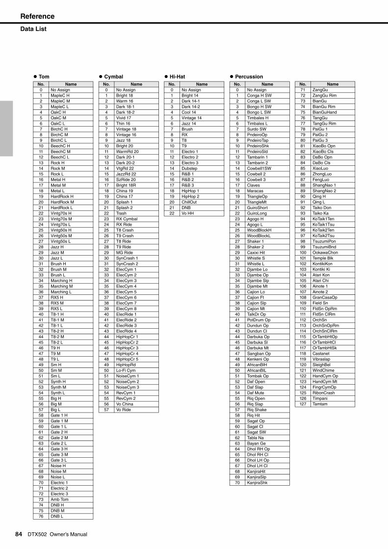
Reference
Data List
84
DTX502 Owner’s ManualTom
No. Name
0 No Assign1 MapleC H2 MapleC M3 MapleC L4 OakC H5 OakC M6 OakC L7 BirchC H8 BirchC M9 BirchC L10 BeechC H11 BeechC M12 BeechC L13 Rock H14 Rock M15 Rock L16 Metal H17 Metal M18 Metal L19 HardRock H20 HardRock M21 HardRock L22 Vintg70s H23 Vintg70s M24 Vintg70s L25 Vintg50s H26 Vintg50s M27 Vintg50s L28 Jazz H29 Jazz M30 Jazz L31 Brush H32 Brush M33 Brush L34 Marching H35 Marching M36 Marching L37 RX5 H38 RX5 M39 RX5 L40 T8-1 H41 T8-1 M42 T8-1 L43 T8-2 H44 T8-2 M45 T8-2 L46 T9 H47 T9 M48 T9 L49 Sm H50 Sm M51 Sm L52 Synth H53 Synth M54 Synth L55 Big H56 Big M57 Big L58 Gate 1 H59 Gate 1 M60 Gate 1 L61 Gate 2 H62 Gate 2 M63 Gate 2 L64 Gate 3 H65 Gate 3 M66 Gate 3 L67 Noise H68 Noise M69 Noise L70 Electric 171 Electric 272 Electric 373 Amb Tom74 DNB H75 DNB M76 DNB L
Cymbal
No. Name
0 No Assign1 Bright 182 Warm 163 Dark 18-14 Dark 18-25 Vivid 176 Thin 167 Vintage 188 Vintage 169 Jazz 1810 Bright 2011 WarmRd 2012 Dark 20-113 Dark 20-214 VtgRd 2215 JazzRd 2216 SzRide 2017 Bright 18R18 China 1919 China 1720 Splash 121 Splash 222 Trash23 RX Cymbal24 RX Ride25 T8 Crash26 T9 Crash27 T8 Ride28 T9 Ride29 MG Ride30 SynCrash 131 SynCrash 232 ElecCym 133 ElecCym 234 ElecCym 335 ElecCym 436 ElecCym 537 ElecCym 638 ElecCym 739 ElecCym 840 ElecRide 141 ElecRide 242 ElecRide 343 ElecRide 444 HipHopCr 145 HipHopCr 246 HipHopCr 347 HipHopCr 448 HipHopCr 549 HipHopRd50 Lo-Fi Cym51 NoiseCym 152 NoiseCym 253 NoiseCym 354 RevCym 155 RevCym 256 Vo China57 Vo Ride
Hi-HatNo. Name
0 No Assign1 Bright 142 Dark 14-13 Dark 14-24 Cool 145 Vintage 146 Jazz 147 Brush8 RX9 T810 T911 Electro 112 Electro 213 Electro 314 Dubstep15 R&B 116 R&B 217 R&B 318 HipHop 119 HipHop 220 ChillOut21 DNB22 Vo HH
PercussionNo. Name
0 No Assign1 Conga H SW2 Conga L SW3 Bongo H SW4 Bongo L SW5 Timbales H6 Timbales L7 Surdo SW8 PndeiroOp9 PndeiroTap10 PndeiroShk11 PndeiroSld12 Tambarin 113 Tambarin 214 Cowbell1SW15 Cowbell 216 Cowbell 317 Claves18 Maracas19 TriangleOp20 TriangleMt21 GuiroShort22 GuiroLong23 Agogo H24 Agogo L25 WoodBlockH26 WoodBlockL27 Shaker 128 Shaker 229 Caxixi Hit30 Whistle S31 Whistle L32 Djambe Lo33 Djambe Op34 Djambe Slp35 Djambe Mt36 Cajion Lo37 Cajion Ft38 Cajion Slp39 Cajion Mt40 TalkDr Op41 PotDrum Op42 Dundun Op43 Dundun Cl44 Darbuka Op45 Darbuka Sl46 Darbuka Mt47 Sangban Op48 Kenkeni Op49 AfricanBlH50 AfricanBlL51 Tombak Op52 Daf Open53 Daf Slap54 Daf Mute55 Riq Open56 Riq Slap57 Riq Shake58 Riq Hit59 Sagat Op60 Sagat Cl61 Sagat SW62 Tabla Na63 Bayan Ge64 Dhol RH Op65 Dhol RH Cl66 Dhol LH Op67 Dhol LH Cl68 KanjiraHit69 KanjiraSlp70 KanjiraShk
71 ZangGu72 ZangGu Rim73 BianGu74 BianGu Rim75 BianGuHand76 TangGu77 TangGu Rim78 PaiGu 179 PaiGu 280 PaiGu 381 XiaoBo Opn82 XiaoBo Cls83 DaBo Opn84 DaBo Cls85 XiaoLuo86 ZhongLuo87 FengLuo88 ShangNao 189 ShangNao 290 Qing H91 Qing L92 Taiko Don93 Taiko Ka94 KoTaik1Ten95 KoTaik1Tsu96 KoTaik2Ten97 KoTaik2Tsu98 TsuzumiPon99 TsuzumiBnd100 OokawaChon101 Temple Blk102 KontikiKon103 Kontiki Ki104 Atari Kon105 Atari Chi106 Ainote 1107 Ainote 2108 GranCasaOp109 Field Sn110 FldSn OpRm111 FldSn ClRm112 OrchSn113 OrchSnOpRm114 OrchSnClRm115 OrTambHtOp116 OrTambHtCl117 OrTambHtSk118 Castanet119 Vibraslap120 SleighBel121 WindChime122 HandCym Op123 HandCym Mt124 FingrCymOp125 RibonCrash126 Timpani127 Tamtam
No. Name
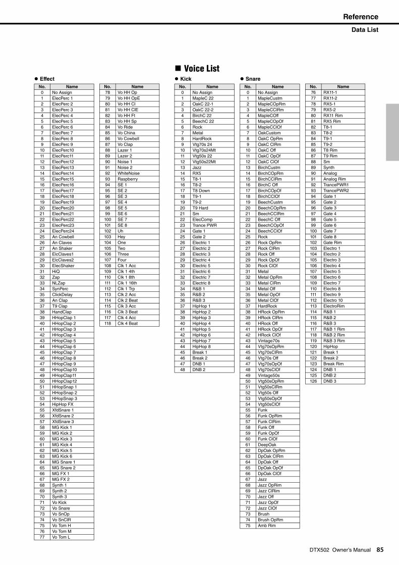
Reference
Data List
Effect
No. Name
0 No Assign1 ElecPerc 12 ElecPerc 23 ElecPerc 34 ElecPerc 45 ElecPerc 56 ElecPerc 67 ElecPerc 78 ElecPerc 89 ElecPerc 910 ElecPerc1011 ElecPerc1112 ElecPerc1213 ElecPerc1314 ElecPerc1415 ElecPerc1516 ElecPerc1617 ElecPerc1718 ElecPerc1819 ElecPerc1920 ElecPerc2021 ElecPerc2122 ElecPerc2223 ElecPerc2324 ElecPerc2425 An Cowbell26 An Claves27 An Shaker28 ElcClaves129 ElcClaves230 ElecShaker31 HiQ32 Zap33 NLZap34 SynPerc35 ClickDelay36 An Clap37 T9 Clap38 HandClap39 HHopClap 140 HHopClap 241 HHopClap 342 HHopClap 443 HHopClap 544 HHopClap 645 HHopClap 746 HHopClap 847 HHopClap 948 HHopClap1049 HHopClap1150 HHopClap1251 HHopSnap 152 HHopSnap 253 HHopSnap 354 HipHop FX55 XfdSnare 156 XfdSnare 257 XfdSnare 358 MG Kick 159 MG Kick 260 MG Kick 361 MG Kick 462 MG Kick 563 MG Kick 664 MG Snare 165 MG Snare 266 MG FX 167 MG FX 268 Synth 169 Synth 270 Synth 371 Vo Kick72 Vo Snare73 Vo SnOp74 Vo SnClR75 Vo Tom H76 Vo Tom M77 Vo Tom L
85
78 Vo HH Op79 Vo HH OpE80 Vo HH Cl81 Vo HH ClE82 Vo HH Ft83 Vo HH Sp84 Vo Ride85 Vo China86 Vo Cowbell87 Vo Clap88 Lazer 189 Lazer 290 Noise 191 Noise 292 WhiteNoise93 Raspberry94 SE 195 SE 296 SE 397 SE 498 SE 599 SE 6100 SE 7101 SE 8102 Uh103 Hey104 One105 Two106 Three107 Four108 Clk 1 Acc109 Clk 1 4th110 Clk 1 8th111 Clk 1 16th112 Clk 1 Trp113 Clk 2 Acc114 Clk 2 Beat115 Clk 3 Acc116 Clk 3 Beat117 Clk 4 Acc118 Clk 4 Beat
No. Name
Voice List Kick Snare
No. Name
0 No Assign1 MapleC 222 OakC 22-13 OakC 22-24 BirchC 225 BeechC 226 Rock7 Metal8 HardRock9 Vtg70s 2410 Vtg70s24Mt11 Vtg50s 2212 Vtg50s22Mt13 Jazz14 RX515 T8-116 T8-217 T8 Down18 T9-119 T9-220 T9 Hard21 Sm22 ElecComp23 Trance PWR24 Gate 125 Gate 226 Electric 127 Electric 228 Electric 329 Electric 430 Electric 531 Electric 632 Electric 733 Electric 834 R&B 135 R&B 236 R&B 337 HipHop 138 HipHop 239 HipHop 340 HipHop 441 HipHop 542 HipHop 643 HipHop 744 HipHop 845 Break 146 Break 247 DNB 148 DNB 2
No. Name
0 No Assign1 MapleCustm2 MapleCOpRm3 MapleCClRm4 MapleCOff5 MapleCOpOf6 MapleCClOf7 OakCustom8 OakC OpRm9 OakC ClRm10 OakC Off11 OakC OpOf12 OakC ClOf13 BirchCustm14 BirchCOpRm15 BirchCClRm16 BirchC Off17 BirchCOpOf18 BirchCClOf19 BeechCustm20 BeechCOpRm21 BeechCClRm22 BeechC Off23 BeechCOpOf24 BeechCClOf25 Rock26 Rock OpRm27 Rock ClRm28 Rock Off29 Rock OpOf30 Rock ClOf31 Metal32 Metal OpRm33 Metal ClRm34 Metal Off35 Metal OpOf36 Metal ClOf37 HardRock38 HRock OpRm39 HRock ClRm40 HRock Off41 HRock OpOf42 HRock ClOf43 Vintage70s44 Vtg70sOpRm45 Vtg70sClRm46 Vtg70s Off47 Vtg70sOpOf48 Vtg70sClOf49 Vintage50s50 Vtg50sOpRm51 Vtg50sClRm52 Vtg50s Off53 Vtg50sOpOf54 Vtg50sClOf55 Funk56 Funk OpRim57 Funk ClRim58 Funk Off59 Funk OpOf60 Funk ClOf61 DeepOak62 DpOak OpRm63 DpOak ClRm64 DpOak Off65 DpOak OpOf66 DpOak ClOf67 Jazz68 Jazz OpRim69 Jazz ClRim70 Jazz Off71 Jazz OpOf72 Jazz ClOf73 Brush74 Brush OpRm75 Amb Rim
DTX502 Owner’s Manual
76 RX11-177 RX11-278 RX5-179 RX5-280 RX11 Rim81 RX5 Rim82 T8-183 T8-284 T9-185 T9-286 T8 Rim87 T9 Rim88 Sm89 Synth90 Analog91 Analog Rim92 TrancePWR193 TrancePWR294 Gate 195 Gate 296 Gate 397 Gate 498 Gate 599 Gate 6100 Gate 7101 Gate 8102 Gate Rim103 Electro 1104 Electro 2105 Electro 3106 Electro 4107 Electro 5108 Electro 6109 Electro 7110 Electro 8111 Electro 9112 Electro 10113 ElectroRim114 R&B 1115 R&B 2116 R&B 3117 R&B 1 Rim118 R&B 2 Rim119 R&B 3 Rim120 HipHop121 Break 1122 Break 2123 Break Rim124 DNB 1125 DNB 2126 DNB 3
No. Name

Reference
Data List
86
DTX502 Owner’s ManualTom
No. Name
0 No Assign1 MapleC H2 MapleC M3 MapleC L4 OakC H5 OakC M6 OakC L7 BirchC H8 BirchC M9 BirchC L10 BeechC H11 BeechC M12 BeechC L13 Rock H14 Rock M15 Rock L16 Metal H17 Metal M18 Metal L19 HardRock H20 HardRock M21 HardRock L22 Vintg70s H23 Vintg70s M24 Vintg70s L25 Vintg50s H26 Vintg50s M27 Vintg50s L28 Jazz H29 Jazz M30 Jazz L31 Brush H32 Brush M33 Brush L34 Marching H35 Marching M36 Marching L37 RX5 H38 RX5 M39 RX5 L40 T8-1 H41 T8-1 M42 T8-1 L43 T8-2 H44 T8-2 M45 T8-2 L46 T9 H47 T9 M48 T9 L49 Sm H50 Sm M51 Sm L52 Synth H53 Synth M54 Synth L55 Big H56 Big M57 Big L58 Gate 1 H59 Gate 1 M60 Gate 1 L61 Gate 2 H62 Gate 2 M63 Gate 2 L64 Gate 3 H65 Gate 3 M66 Gate 3 L67 Noise H68 Noise M69 Noise L70 Electric 171 Electric 272 Electric 373 Amb Tom74 DNB H75 DNB M76 DNB L
CymbalNo. Name
0 No Assign1 Bright182 Bright18Eg3 Bright18Cp4 Warm 165 Warm 16Eg6 Warm 16Cp7 Dark18-18 Dark18-1Eg9 Dark18-1Cp10 Dark18-211 Dark18-2Eg12 Dark18-2Cp13 Vivid 1714 Vivid 17Eg15 Vivid 17Cp16 Thin 1617 Thin 16Eg18 Thin 16Cp19 Vintage 1820 Vintg 18Eg21 Vintg 18Cp22 Vintage 1623 Vintg 16Eg24 Vintg 16Cp25 Jazz 1826 Jazz 18Eg27 Jazz 18Cp28 Bright2029 Bright20Eg30 Bright20Cp31 WarmRd2032 WarmRd20Eg33 WarmRd20Cp34 Dark20-135 Dark20-1Eg36 Dark20-1Cp37 Dark20-238 Dark20-2Eg39 Dark20-2Cp40 VtgRd 2241 VtgRd 22Eg42 VtgRd 22Cp43 JazzRd2244 JazzRd22Eg45 JazzRd22Cp46 SzRide 2047 SzRd 20Eg48 SzRd 20Cp49 Bright18R50 China 1951 China 1752 Splash 153 Splash 254 Trash55 RX11 Crash56 RX5 Crash57 RX11 Ride58 RX5 RdEg59 RX5 RdCp60 T8 Crash61 T9 Crash62 T8 Ride63 T9 Ride64 SynCrash 165 SynCrash 266 ElecCym 167 ElecCym 268 ElecCym 369 ElecCym 470 ElecCym 571 ElecCym 672 ElecCym 773 ElecCym 8
74 ElecRide 175 ElecRd 1Eg76 ElecRd 1Cp77 ElecRd 2Cp78 ElecRide 379 ElecRide 480 HipHopCr 181 HipHopCr 282 HipHopCr 383 HipHopCr 484 HipHopCr 585 HipHopRd86 HipHopRdCp87 Lo-Fi Cym88 NoiseCym 189 NoiseCym 290 NoiseCym 391 RevCym 192 RevCym 2
No. Name
Hi-HatNo. Name
0 No Assign1 Bright14Op2 Brt14OpEg3 Brt14OpCp4 Bright14Cl5 Brt14ClEg6 Brt14ClCp7 Bright14Ft8 Bright14Sp9 Dark14-1Op10 Dk14-1OpEg11 Dk14-1OpCp12 Dark14-1Cl13 Dk14-1ClEg14 Dk14-1ClCp15 Dark14-1Ft16 Dark14-1Sp17 Dark14-2Op18 Dk14-2OpEg19 Dk14-2OpCp20 Dark14-2Cl21 Dk14-2ClEg22 Dk14-2ClCp23 Dark14-2Ft24 Dark14-2Sp25 Cool14 Op26 Cool14OpEg27 Cool14OpCp28 Cool14 Cl29 Cool14ClEg30 Cool14ClCp31 Cool14 Ft32 Cool14 Sp33 Vintg14 Op34 Vtg14 OpEg35 Vtg14 OpCp36 Vintg14 Cl37 Vtg14 ClEg38 Vtg14 ClCp39 Vintg14 Ft40 Vintg14 Sp41 Jazz14 Op42 Jazz14OpEg43 Jazz14OpCp44 Jazz14 Cl45 Jazz14ClEg46 Jazz14ClCp47 Jazz14 Ft48 Jazz14 Sp49 RX11 Op50 RX5 Op51 RX11 Cl52 RX5 Cl53 T8 Op54 T8 Cl55 T9 Op56 T9 Cl57 Elec1 Op58 Elec1 OpEg59 Elec1 Cl60 Elec1 ClEg61 Elec1 Ft62 Elec1 Sp63 Elec2 Op64 Elec2 OpEg65 Elec2 Cl66 Elec2 ClEg67 Elec2 Ft68 Elec2 Sp69 Elec3 Op70 Elec3 OpEg71 Elec3 Cl72 Elec3 ClEg73 Elec4 Cl
74 R&B1 Op75 R&B1 Cl76 R&B1 Ft77 R&B1 Sp78 R&B2 Op79 R&B2 Ft80 R&B3 Op81 R&B3 Cl82 R&B3 Ft83 HipHop1 Op84 HHop1 OpEg85 HipHop1 Cl86 HHop1 ClEg87 HipHop1 Ft88 HipHop2 Op89 HipHop2 Cl90 HHop2 ClEg91 HipHop2 Ft92 DNB Op93 DNB Cl94 DNB Ft95 Machine 196 Machine 297 Machine 398 Machine 499 Analog 1100 Analog 2101 Analog 3102 Analog 4103 Analog 5104 FX HiHat
No. Name
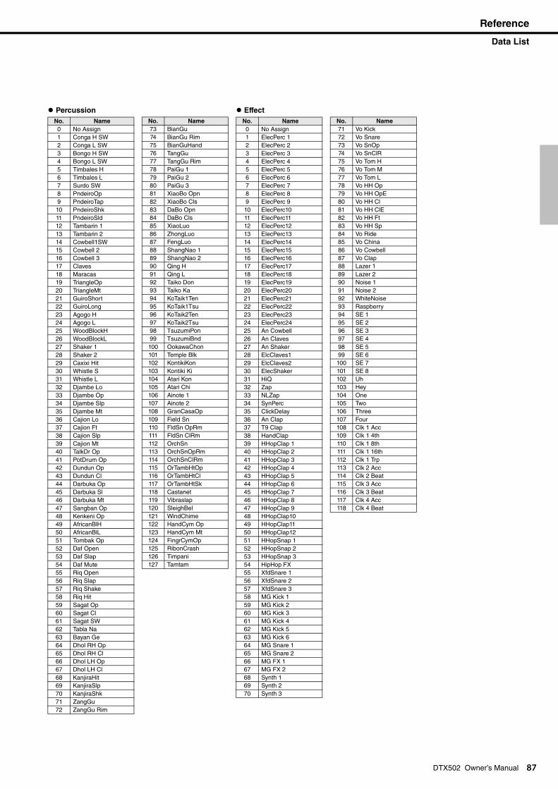
Reference
Data List
Percussion
No. Name
0 No Assign1 Conga H SW2 Conga L SW3 Bongo H SW4 Bongo L SW5 Timbales H6 Timbales L7 Surdo SW8 PndeiroOp9 PndeiroTap10 PndeiroShk11 PndeiroSld12 Tambarin 113 Tambarin 214 Cowbell1SW15 Cowbell 216 Cowbell 317 Claves18 Maracas19 TriangleOp20 TriangleMt21 GuiroShort22 GuiroLong23 Agogo H24 Agogo L25 WoodBlockH26 WoodBlockL27 Shaker 128 Shaker 229 Caxixi Hit30 Whistle S31 Whistle L32 Djambe Lo33 Djambe Op34 Djambe Slp35 Djambe Mt36 Cajion Lo37 Cajion Ft38 Cajion Slp39 Cajion Mt40 TalkDr Op41 PotDrum Op42 Dundun Op43 Dundun Cl44 Darbuka Op45 Darbuka Sl46 Darbuka Mt47 Sangban Op48 Kenkeni Op49 AfricanBlH50 AfricanBlL51 Tombak Op52 Daf Open53 Daf Slap54 Daf Mute55 Riq Open56 Riq Slap57 Riq Shake58 Riq Hit59 Sagat Op60 Sagat Cl61 Sagat SW62 Tabla Na63 Bayan Ge64 Dhol RH Op65 Dhol RH Cl66 Dhol LH Op67 Dhol LH Cl68 KanjiraHit69 KanjiraSlp70 KanjiraShk71 ZangGu72 ZangGu Rim
DTX502 Owner’s Manual 87
73 BianGu74 BianGu Rim75 BianGuHand76 TangGu77 TangGu Rim78 PaiGu 179 PaiGu 280 PaiGu 381 XiaoBo Opn82 XiaoBo Cls83 DaBo Opn84 DaBo Cls85 XiaoLuo86 ZhongLuo87 FengLuo88 ShangNao 189 ShangNao 290 Qing H91 Qing L92 Taiko Don93 Taiko Ka94 KoTaik1Ten95 KoTaik1Tsu96 KoTaik2Ten97 KoTaik2Tsu98 TsuzumiPon99 TsuzumiBnd100 OokawaChon101 Temple Blk102 KontikiKon103 Kontiki Ki104 Atari Kon105 Atari Chi106 Ainote 1107 Ainote 2108 GranCasaOp109 Field Sn110 FldSn OpRm111 FldSn ClRm112 OrchSn113 OrchSnOpRm114 OrchSnClRm115 OrTambHtOp116 OrTambHtCl117 OrTambHtSk118 Castanet119 Vibraslap120 SleighBel121 WindChime122 HandCym Op123 HandCym Mt124 FingrCymOp125 RibonCrash126 Timpani127 Tamtam
No. Name
EffectNo. Name
0 No Assign1 ElecPerc 12 ElecPerc 23 ElecPerc 34 ElecPerc 45 ElecPerc 56 ElecPerc 67 ElecPerc 78 ElecPerc 89 ElecPerc 910 ElecPerc1011 ElecPerc1112 ElecPerc1213 ElecPerc1314 ElecPerc1415 ElecPerc1516 ElecPerc1617 ElecPerc1718 ElecPerc1819 ElecPerc1920 ElecPerc2021 ElecPerc2122 ElecPerc2223 ElecPerc2324 ElecPerc2425 An Cowbell26 An Claves27 An Shaker28 ElcClaves129 ElcClaves230 ElecShaker31 HiQ32 Zap33 NLZap34 SynPerc35 ClickDelay36 An Clap37 T9 Clap38 HandClap39 HHopClap 140 HHopClap 241 HHopClap 342 HHopClap 443 HHopClap 544 HHopClap 645 HHopClap 746 HHopClap 847 HHopClap 948 HHopClap1049 HHopClap1150 HHopClap1251 HHopSnap 152 HHopSnap 253 HHopSnap 354 HipHop FX55 XfdSnare 156 XfdSnare 257 XfdSnare 358 MG Kick 159 MG Kick 260 MG Kick 361 MG Kick 462 MG Kick 563 MG Kick 664 MG Snare 165 MG Snare 266 MG FX 167 MG FX 268 Synth 169 Synth 270 Synth 3
71 Vo Kick72 Vo Snare73 Vo SnOp74 Vo SnClR75 Vo Tom H76 Vo Tom M77 Vo Tom L78 Vo HH Op79 Vo HH OpE80 Vo HH Cl81 Vo HH ClE82 Vo HH Ft83 Vo HH Sp84 Vo Ride85 Vo China86 Vo Cowbell87 Vo Clap88 Lazer 189 Lazer 290 Noise 191 Noise 292 WhiteNoise93 Raspberry94 SE 195 SE 296 SE 397 SE 498 SE 599 SE 6100 SE 7101 SE 8102 Uh103 Hey104 One105 Two106 Three107 Four108 Clk 1 Acc109 Clk 1 4th110 Clk 1 8th111 Clk 1 16th112 Clk 1 Trp113 Clk 2 Acc114 Clk 2 Beat115 Clk 3 Acc116 Clk 3 Beat117 Clk 4 Acc118 Clk 4 Beat
No. Name
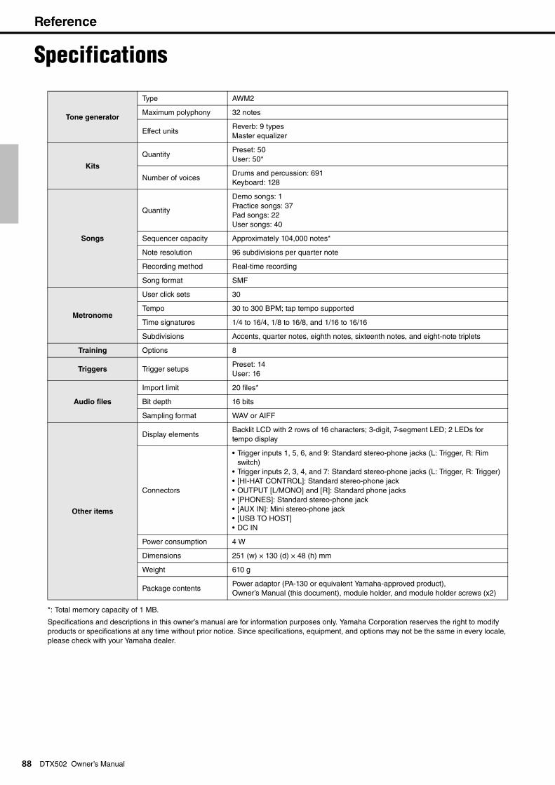
Reference
8
Specifications
8
DTX502 Owner’s Manual*: Total memory capacity of 1 MB.
Specifications and descriptions in this owner’s manual are for information purposes only. Yamaha Corporation reserves the right to modify products or specifications at any time without prior notice. Since specifications, equipment, and options may not be the same in every locale, please check with your Yamaha dealer.
Tone generator
Type AWM2
Maximum polyphony 32 notes
Effect unitsReverb: 9 typesMaster equalizer
Kits
QuantityPreset: 50User: 50*
Number of voicesDrums and percussion: 691Keyboard: 128
Songs
Quantity
Demo songs: 1Practice songs: 37Pad songs: 22User songs: 40
Sequencer capacity Approximately 104,000 notes*
Note resolution 96 subdivisions per quarter note
Recording method Real-time recording
Song format SMF
Metronome
User click sets 30
Tempo 30 to 300 BPM; tap tempo supported
Time signatures 1/4 to 16/4, 1/8 to 16/8, and 1/16 to 16/16
Subdivisions Accents, quarter notes, eighth notes, sixteenth notes, and eight-note triplets
Training Options 8
Triggers Trigger setupsPreset: 14User: 16
Audio files
Import limit 20 files*
Bit depth 16 bits
Sampling format WAV or AIFF
Other items
Display elementsBacklit LCD with 2 rows of 16 characters; 3-digit, 7-segment LED; 2 LEDs for tempo display
Connectors
• Trigger inputs 1, 5, 6, and 9: Standard stereo-phone jacks (L: Trigger, R: Rim switch)
• Trigger inputs 2, 3, 4, and 7: Standard stereo-phone jacks (L: Trigger, R: Trigger)• [HI-HAT CONTROL]: Standard stereo-phone jack• OUTPUT [L/MONO] and [R]: Standard phone jacks• [PHONES]: Standard stereo-phone jack• [AUX IN]: Mini stereo-phone jack• [USB TO HOST]• DC IN
Power consumption 4 W
Dimensions 251 (w) × 130 (d) × 48 (h) mm
Weight 610 g
Package contentsPower adaptor (PA-130 or equivalent Yamaha-approved product), Owner’s Manual (this document), module holder, and module holder screws (x2)
Reference
Index
89
DTX502 Owner’s ManualSymbols[ ] connector ....................... 11[ ] button .............................................. 11 buttons ...................................... 10[ ] button ......................................... 10[ ] (Standby/On) button ....................... 10[AUX IN] jack ......................................... 11[HI-HAT CONTROL] jack ....................... 11[KIT] button ............................................ 10OUTPUT [L/MONO] and [R] jacks ......... 11[PHONES] jack ...................................... 11[SAVE/ENTER] button ........................... 11[SHIFT] button ....................................... 10[SONG] button ....................................... 10[USB TO HOST] terminal ................ 11, 79VOLUME [+] and [–] buttons ................. 10
AAcoustic Drums ..................................... 77Alternate Group ..................................... 61Auto Power-Off ...................................... 75Auto Power-Off time .............................. 13
BBell shots ............................................... 18Bow shots ........................................ 17, 18
CChange Up ............................................ 44Choking ................................................. 18Clear User Kit ........................................ 65Click Set .......................................... 32, 37Closed sounds ....................................... 17Computer ............................................... 79Control Panel ......................................... 10Copy Pad ............................................... 64Copy Trigger .......................................... 71Cord clip ................................................ 11Count-In ................................................. 28Crosstalk ................................................ 70Crosstalk Pads ...................................... 70CSAT924A ....................................... 77, 78Cup shots .............................................. 17Cutoff Frequency ................................... 59Cymbal Sizes ......................................... 22Cymbals ................................................. 18
DData Dial ................................................ 10Decay .................................................... 59Default Settings ..................................... 14Deleting ................................................. 54Difficulty Level ....................................... 72Double Bass Switch ............................... 61DT10/DT20 ............................................ 77
EEdge shots ....................................... 17, 18
FFactory Set ............................................ 75Fast Blast ............................................... 49Fast Blast Timer .................................... 73Foot Close Position ............................... 65Foot-close sounds ................................. 17
GGain .......................................................68Groove Check ........................................38
HHeadphones ...........................................12Hi-hat Splash Sensitivity ........................65Hi-hat splash sounds .............................17Hold Mode ..............................................61
IIgnore Timing .........................................72Initial Setup ............................................13Input Sources .........................................29Instrument ..............................................20Instrument Volumes ...............................19
KKit .....................................................19, 20Kit Lock ..................................................73KU100 ....................................................76
LLayers ....................................................57LCD screen ............................................10Looping a Song ......................................28
MMaster Equalizer ....................................74Master Tuning ........................................74Measure Break .......................................41Menu Mode ............................................55Metronome .............................................31Metronome lights ...................................10Metronome Output .................................74MIDI Channel .........................................60MIDI Control Change .............................63MIDI Gate Time ......................................60MIDI Note Number .................................60MIDI Program Change ...........................63Minimum Level .......................................68Minimum Velocity ...................................69Mixer settings .........................................57Music Player ..........................................12Muted Volume ........................................73Muting ..............................................18, 27
NNoise Filter .............................................69Number display ......................................10Number Display Function .......................74
OOpen sounds ..........................................17
PPad Control ............................................62Pad Function ..........................................66Pad Gate ................................................46Pad Gate Group .....................................72Pad set .....................................................7Pad Songs .............................................29Pad Type ................................................68Part Mute ...............................................47PCY90AT ...............................................76PDF ..........................................................6
Play mode .............................................. 30Power adaptor ....................................... 12Practice songs ....................................... 26
QQuantize ................................................ 52
RRear Panel ............................................. 11Recording .............................................. 51Reference Manual ................................. 79Reject Time ........................................... 69Repeat Mode ......................................... 30Restore .................................................. 75Reverb Return ....................................... 62Reverb Send (Source) ........................... 60Reverb Send (Voices) ........................... 61Reverb Type .......................................... 62Rhythm Gate ......................................... 40
SSensitivity .............................................. 19Separately Sold Accessories ................. 76Snare ..................................................... 16Snare Adjustment .................................. 62Song ...................................................... 26Speakers ............................................... 12Stereo Panning ................................ 24, 59Storing your settings .............................. 56
TTapping the Tempo ............................... 36Tempo ................................................... 62Tempo Up/Down .................................... 42Timer ..................................................... 72Training Mode ........................................ 38Trigger input jacks ................................. 11Trigger Setup ................................... 13, 66Trigger Setup Link ................................. 63Tuning .............................................. 22, 59
UUSB ....................................................... 79USB-MIDI driver .................................... 79User kits ................................................. 25User songs ............................................ 51
VVelocity Curve ....................................... 67Voice ................................................ 20, 58Volume ............................................ 15, 59
WWait Time .............................................. 69Wave Voice ........................................... 21
YY-cable .................................................. 11
[<]/[>]
90 DTX502 Owner’s Manual / Mode d’emploi
DTX502 Owner’s Manual / Mode d’emploi 91
(weee_eu_en_01)
(weee_eu_fr_01)
(standby)
(bottom_en_01)
(bottom_fr_01)
Information for Users on Collection and Disposal of Old Equipment
This symbol on the products, packaging, and/or accompanying documents means that used electrical and electronic products should not be mixed with general household waste.For proper treatment, recovery and recycling of old products, please take them to applicable collection points, in accor-dance with your national legislation and the Directives 2002/96/EC.
By disposing of these products correctly, you will help to save valuable resources and prevent any potential negative effects on human health and the environment which could otherwise arise from inappropriate waste handling.
For more information about collection and recycling of old products, please contact your local municipality, your waste disposal service or the point of sale where you purchased the items.
[For business users in the European Union]
If you wish to discard electrical and electronic equipment, please contact your dealer or supplier for further information.
[Information on Disposal in other Countries outside the European Union]
This symbol is only valid in the European Union. If you wish to discard these items, please contact your local authorities or dealer and ask for the correct method of disposal.
Information concernant la Collecte et le Traitement des déchets d’équipements électriques et électroniques.
Le symbole sur les produits, l'emballage et/ou les documents joints signifie que les produits électriques ou électron-iques usagés ne doivent pas être mélangés avec les déchets domestiques habituels.Pour un traitement, une récupération et un recyclage appropriés des déchets d’équipements électriques et électroni-ques, veuillez les déposer aux points de collecte prévus à cet effet, conformément à la réglementation nationale et aux Directives 2002/96/EC.
En vous débarrassant correctement des déchets d’équipements électriques et électroniques, vous contribuerez à la sauvegarde de précieuses ressources et à la prévention de potentiels effets négatifs sur la santé humaine qui pour-raient advenir lors d'un traitement inapproprié des déchets.
Pour plus d'informations à propos de la collecte et du recyclage des déchets d’équipements électriques et électroni-ques, veuillez contacter votre municipalité, votre service de traitement des déchets ou le point de vente où vous avez acheté les produits.
[Pour les professionnels dans l'Union Européenne]
Si vous souhaitez vous débarrasser des déchets d’équipements électriques et électroniques veuillez contacter votre vendeur ou fournisseur pour plus d'informations.
[Information sur le traitement dans d'autres pays en dehors de l'Union Européenne]
Ce symbole est seulement valable dans l'Union Européenne. Si vous souhaitez vous débarrasser de déchets d’équipe-ments électriques et électroniques, veuillez contacter les autorités locales ou votre fournisseur et demander la méth-ode de traitement appropriée.
OBSERVERA!Apparaten kopplas inte ur växelströmskällan (nätet) så länge som den ar ansluten till vägguttaget, även om själva apparaten har stängts av.
ADVARSEL: Netspændingen til dette apparat er IKKE afbrudt, sålænge netledningen sidder i en stikkontakt, som er tændt — også sel-vom der er slukket på apparatets afbryder.
VAROITUS: Laitteen toisiopiiriin kytketty käyttökytkin ei irroita koko laitetta verkosta.
The model number, serial number, power requirements, etc., may be found on or near the name plate, which is at the bottom of the unit. You should note this serial number in the space provided below and retain this manual as a permanent record of your purchase to aid identification in the event of theft.
Model No.
Serial No.
Le numéro de modèle, le numéro de série, l'alimentation requise, etc., se trouvent sur ou près de la plaque signalétique du produit, située dans la partie inférieure de l'unité. Notez le numéro de série dans l'espace fourni ci-dessous et conservez ce manuel en tant que preuve permanente de votre achat afin de faciliter l'identification du produit en cas de vol.
N° de modèle
N° de série
Yamaha web sitehttp://www.yamaha.com/
Yamaha Downloadshttp://download.yamaha.com/
U.R.G., Digital Musical Instruments Division© 2013 Yamaha Corporation
211POGR*.*-01A0Printed in Indonesia
ZE12040