Embed Size (px)
Citation preview
Convey Personality Development Kit Reference Manual
April 2012
Version 5.2
900-000002-000
Convey ComputerTM Corporation 2008-2012.
All Rights Reserved.
1302 East Collins
Richardson, TX 75081

Convey PDK Reference Manual v5.2 i
The Information in this document is provided for use with Convey Computer Corporation (“Convey”) products. No license, express or implied, to any intellectual property associated with this document or such products is granted by this document.
All products described in this document whose name is prefaced by “Convey” or “Convey enhanced “ (“Convey products”) are owned by Convey Computer Corporation (or those companies that have licensed technology to Convey) and are protected by patents, trade secrets, copyrights or other industrial property rights.
The Convey products described in this document may still be in development. The final form of each product and release date thereof is at the sole and absolute discretion of Convey. Your purchase, license and/or use of Convey products shall be subject to Convey’s then current sales terms and conditions.
Trademarks
The following are trademarks of Convey Computer Corporation:
The Convey Computer Logo:
Convey Computer
Convey HC-1
Convey HC-1ex
Convey HC-2
Convey HC-1ex
Trademarks of other companies
Intel is a registered trademark of Intel Corporation
Adobe and Adobe Reader are registered trademarks of Adobe Systems Incorporated
Linux is a registered trademark of Linus Torvalds
Xilinx, Virtex and ISE are registered trademarks of Xilinx in the United States and other countries.
ChipScope, CORE Generator and PlanAhead are trademarks of Xilinx, Inc.
Convey PDK Reference Manual v5.2 ii
Revisions
Version Description
1.0 May 2008. Original printing.
2.0 August 2008. Updates for second PDK release.
2.01 December 2008.
2.02 June 2009. Updated tool flow.
2.03 June 2009. Updated logo and trademarks.
2.04 September 2009. Changed AE-AE interface definition. Updated Sample personality.
2.05 October 2009. Added description of memory organization for scatter/gather DIMMs.
3.0 April 2010. Added instructions for running Xilinx Chipscope. Updated binary interleave figure. Removed appendix section “Future Version of PDK.” Removed response port signals from MC diagrams and from signal description. Added write flush signals to MC interface diagram and signal description. Removed instruction mask signal from dispatch interface diagram and from signal description. Added instructions for installing the FPGA image (section 9.4.7). Removed AeId setting in simulation configuration file (9.4.5.4.1).
3.01 May 2010. Changed site local personality signature range (10.1.1)
4.0 July 2010. Added PDK instruction set and machine state (section 5). Removed description of RIM/WIM/CIM fields of the AEG register. Added AEEM register description. Added split read/write request stall signals to MC interface description.
4.1 December 2010. Updated memory ports: removed mc_rs_port signals, fixed mc_rsp_push and mc_rsp_stall signal definitions. Corrected format of Mov Sa,Immed,AEG instruction. Fixed hyperlinks to documents. Added description of new project structure. Added HC-1ex support and description of CNY_PDK_PLATFORM variable. Updated path to sample personality.
4.2 June 2011. Added detail to AE Software Development, and FPGA Development sections including the MC and Management Interfaces. Added General Resources section under FPGA Development.
5.0 November 2011. Moved document to the Convey Doc Template. Decode information added to Appendix A. Various miscellaneous clarifications and corrections. Changed signal names to match verilog. AE – AE Interface updates. Added Read Order Cache, Strong Order Cache, Crossbar and Async Optional Interfaces, updated Sample Personality information changes
Convey PDK Reference Manual v5.2 iii
in this release. Added Appendix B – PDK Variables and Appendix E – Other PDK Resources.
5.1 March 2012. Added HC-1ex FPGA resource utilization and floorplan. Updated simulation makefile example. Updated instructions for copying personality directory. Removed unused STL register from sample personality definition. Updated sample personality program assembly code example. Fixed the size argument in AeMemLoad and AeMemStore simulator function calls. Updated write flush description.
5.2 April 2012. Added support of optional performance monitoring. Changes in support of HC-2 / HC-2ex
Convey PDK Reference Manual v5.2 iv
Table of Contents
1 Overview ......................................................................................................... 1
1.1 Introduction ........................................................................................................ 1
1.1.1 How to Use This Manual ............................................................................................ 1
1.1.2 Related Documents ................................................................................................... 1
2 Coprocessor Architecture ............................................................................... 2
3 PDK Components ........................................................................................... 3
4 Requirements ................................................................................................. 4
4.1 Convey Packages .............................................................................................. 4
4.2 Other Requirements ........................................................................................... 4
5 PDK Personalities ........................................................................................... 5
5.1 Supported Machine State ................................................................................... 5
5.1.1 AEEM – Application Engine Execution Mask ............................................................ 5
5.1.2 AEC – Application Engine Control Register .............................................................. 6
5.1.3 AES – Application Engine Status ............................................................................... 7
5.1.4 AEG Register ............................................................................................................. 8
5.2 Context Save and Restore ................................................................................. 8
5.3 PDK Instruction Set Architecture ........................................................................ 8
5.3.1 Masked/Directed Instructions .................................................................................... 9
5.3.2 Instruction Set Organized by Function ....................................................................... 9
6 PDK Development Steps .............................................................................. 13
6.1 Analyze Application .......................................................................................... 13
6.2 Evaluate Hardware Options .............................................................................. 13
6.3 Define Custom Instructions............................................................................... 13
6.4 Develop Software Model of Custom Personality ............................................... 13
6.5 Replace Application Kernel with Call to Coprocessor ....................................... 14
6.6 Compile Application with Convey Compiler ...................................................... 14
6.7 Simulate Application with Convey Architecture Simulator ................................. 14
6.8 Develop FPGA Hardware ................................................................................. 14
6.9 Simulate Hardware in Convey Simulation Environment .................................... 14
6.10 Integrate with Convey Hardware ................................................................... 14
7 Custom AE Software Model Development .................................................... 16
7.1 Conceptual Overview of the Software Modeling Process .................................. 16
7.2 Developing the AE Software Model .................................................................. 17
7.2.1 Functions implemented by Custom Personality ...................................................... 18
7.2.2 Functions callable by Custom Personality ............................................................... 18
7.3 Compiling the Model ......................................................................................... 20
8 Application Development/Modification .......................................................... 21
Convey PDK Reference Manual v5.2 v
8.1 Add Coprocessor Function Calls to Application ................................................ 21
8.2 Running the Application on the Architecture Simulator ..................................... 21
8.3 Debug Application with GDB ............................................................................ 21
8.4 Debug CAE Emulator Client with GDB ............................................................. 21
8.5 Defining AEG Registers for use within GDB ..................................................... 22
8.5.1 Personality Register Description File ....................................................................... 22
8.5.2 Built In and User Defined Descriptions .................................................................... 22
8.5.3 Bitfield Definitions .................................................................................................... 22
8.5.4 Union Definition ........................................................................................................ 23
8.5.5 Register Definition .................................................................................................... 24
8.5.6 User Commands ...................................................................................................... 25
9 FPGA Development ...................................................................................... 26
9.1 Introduction ...................................................................................................... 26
9.2 FPGA Technology ............................................................................................ 26
9.3 Hardware Interfaces ......................................................................................... 26
9.3.1 Application Engine (AE) FPGA block diagram ........................................................ 26
9.3.2 Dispatch Interface .................................................................................................... 27
9.3.3 Memory Controller Interface .................................................................................... 31
9.3.4 Management Interface ............................................................................................. 44
9.3.5 General Resources .................................................................................................. 52
9.3.6 Optional AE-AE Interface ......................................................................................... 54
9.3.7 Optional MC Interface Functionality ......................................................................... 58
9.3.8 Other Optional Functionality .................................................................................... 65
9.3.9 Diagnostic Resources .............................................................................................. 66
9.4 FPGA Tool Flow ............................................................................................... 67
9.4.1 PDK Revisions ......................................................................................................... 67
9.4.2 PDK Project ............................................................................................................. 67
9.4.3 PDK Variables .......................................................................................................... 68
9.4.4 PDK Makefiles ......................................................................................................... 68
9.4.5 Simulation ................................................................................................................ 68
9.4.6 Xilinx Tool Flow ........................................................................................................ 73
9.4.7 Installing the FPGA Image ....................................................................................... 76
9.4.8 Debugging with Chipscope ...................................................................................... 76
10 Setting up the Custom Personality ............................................................. 78
10.1.1 Personality Number and Nicknames ....................................................................... 78
10.1.2 Defining the Personality for the Convey Simulator, Assembler, and Compilers...... 79
11 Sample Custom Personality ....................................................................... 81
11.1 Overview ....................................................................................................... 81
11.2 Sample Personality Machine State Extensions.............................................. 82
11.2.1 MA1 Register ........................................................................................................... 83
11.2.2 MA2 Register ........................................................................................................... 83
11.2.3 MA3 Register ........................................................................................................... 83
Convey PDK Reference Manual v5.2 vi
11.2.4 CNT Register ........................................................................................................... 83
11.2.5 SAE[3:0] Register .................................................................................................... 83
11.3 Exceptions .................................................................................................... 83
11.4 Sample Personality Instructions .................................................................... 84
11.4.1 CAEP00 – Memory-to-Memory Add ........................................................................ 84
11.5 Sample Personality Program ......................................................................... 85
11.6 Running the Sample Application ................................................................... 86
11.6.1 Copy Sample AE and Sample Application............................................................... 86
11.6.2 Build the Sample AE and Sample Application ......................................................... 86
11.6.3 Run the Application .................................................................................................. 86
A PDK Instructions ........................................................................................... 87
CAEP00 – CAEP1F – Custom AE Instruction ....................................................................... 88
MOV – Move from AEC or AES Register to A Register ......................................................... 89
MOV – Move A Register to AEC or AES Register ................................................................. 90
MOV – Move A Register to AEEM Control Register .............................................................. 91
MOV – Move AEEM Control Register to an A Register ......................................................... 92
MOV – Move AEGcnt Value to A Register ............................................................................. 93
MOV – Move AEG Element to A Reg. with Immed. Index ..................................................... 94
MOV – Move A-Reg. to AEG Element with Immed. Index ..................................................... 95
MOV – Move AEG Element to Scalar with Immed. Index ...................................................... 96
MOV – Move Scalar to AEG Element with Immed. Index ...................................................... 97
MOV – Move Scalar to AEG Register Element ...................................................................... 98
MOV – Move AEG Register Element to Scalar ...................................................................... 99
B PDK Variables............................................................................................. 100
C Definitions ................................................................................................... 101
D Packaging the Custom Personality ............................................................. 102
Packaging Overview ................................................................................................ 102
Packaging Requirements ......................................................................................... 102
Step by Step Packaging Instructions ........................................................................ 103
Creating Debian Packages ...................................................................................... 105
Using alien ............................................................................................................... 105
Using older versions of alien .................................................................................... 106
E Other Resources for PDK Users ................................................................. 107
Convey Support ....................................................................................................... 107
FPGA Design ........................................................................................................... 107
Application Programming ......................................................................................... 107
System Information .................................................................................................. 107
F Customer Support Procedures ................................................................... 109
Convey PDK Reference Manual v5.2 1
1 Overview
1.1 Introduction
The Convey coprocessor is a programmable hardware solution to increase application performance beyond what is typically possible in a standard x86 system. Because of its programmable nature, the hardware allows the architecture to be reconfigured to meet the needs of the application. These reconfigurable instruction sets are called personalities.
Convey provides some personalities, such as the single-precision and double-precision vector personalities, that can be used to accelerate certain applications. Some applications, however, require specialized functionality that is not provided by these personalities. As a result, Convey has designed a framework to enable the development of custom personalities, including instruction set extensions to allow execution of custom instructions. The Personality Development Kit (PDK) provides all the hardware, software and simulation interfaces necessary to implement a custom personality on the Convey family of products.
This manual describes the Convey Personality Development Kit. It is intended for hardware and software engineers developing custom personalities for the Convey coprocessor, as well as those developing or debugging custom applications that use custom personalities.
1.1.1 How to Use This Manual
Before reading this document, the reader should generally be familiar with the Convey coprocessor architecture. The “System Organization” chapter of the Convey Reference Manual provides a good architectural overview.
This manual is intended to be both a design guide as well as a reference manual. The Coprocessor Architecture chapter describes the architecture of the Convey Coprocessor focusing on the Application Engine FPGA. Chapter 6 outlines the process of developing a custom personality and references other chapters and documents for more detailed information on each subject.
This document contains clickable hyperlinks to other Convey documents.
1.1.2 Related Documents
Three other documents provide general information about the Convey Coprocessor:
The Convey Reference Manual provides a detailed description of the coprocessor architecture, including scalar machine state and instructions
The Convey Programmers Guide describes how to write coprocessor routines in assembly language, and how to link those with C/C++, and Fortran host processor routines. It also describes how to debug coprocessor and host processor code using the Convey simulator and Convey’s enhanced GDB debugger
The Convey System Administration Guide contains installation instructions and system requirements for Convey software.
Convey PDK Reference Manual v5.2 2
2 Coprocessor Architecture
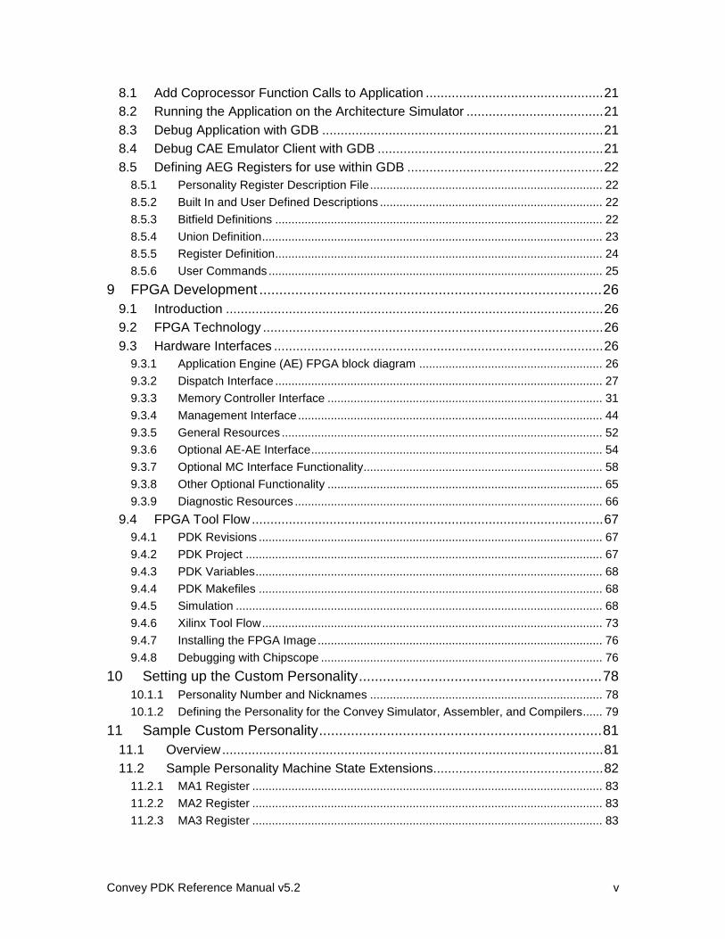
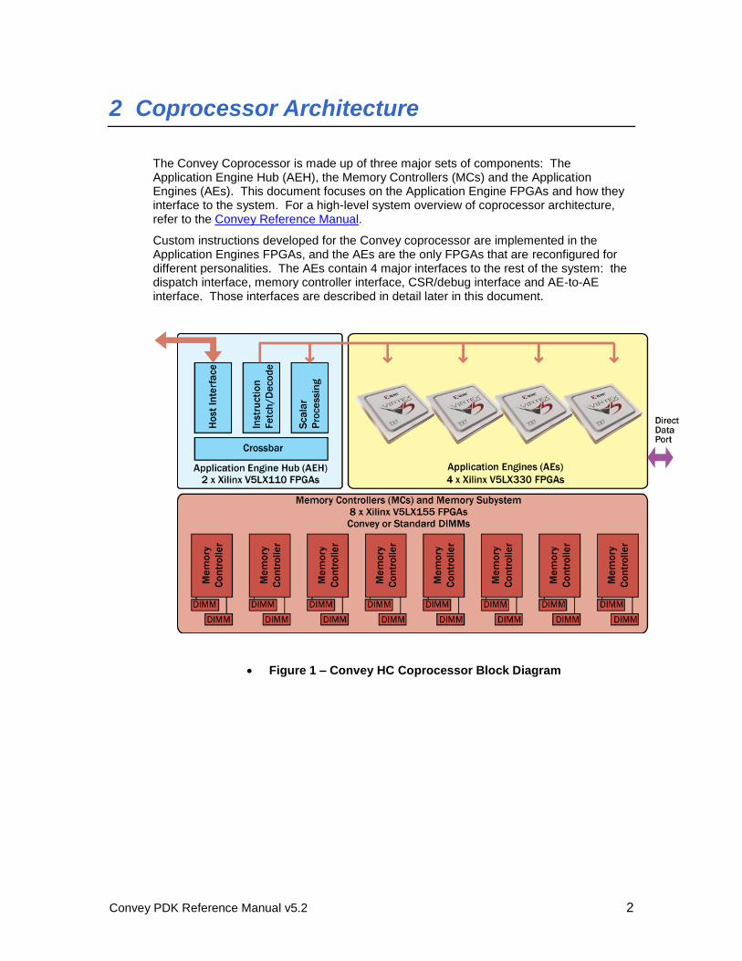
The Convey Coprocessor is made up of three major sets of components: The Application Engine Hub (AEH), the Memory Controllers (MCs) and the Application Engines (AEs). This document focuses on the Application Engine FPGAs and how they interface to the system. For a high-level system overview of coprocessor architecture, refer to the Convey Reference Manual.
Custom instructions developed for the Convey coprocessor are implemented in the Application Engines FPGAs, and the AEs are the only FPGAs that are reconfigured for different personalities. The AEs contain 4 major interfaces to the rest of the system: the dispatch interface, memory controller interface, CSR/debug interface and AE-to-AE interface. Those interfaces are described in detail later in this document.
Figure 1 – Convey HC Coprocessor Block Diagram
Convey PDK Reference Manual v5.2 3
3 PDK Components
The Personality Development Kit includes the following components:
Convey PDK Reference Manual (this document)
The PDK Reference Manual defines the hardware and simulation interfaces that make up the Personality Development kit. It provides step-by-step instructions for developing and packaging a custom personality.
FPGA hardware interfaces
Provided as Verilog modules, these interfaces connect custom personality hardware to instruction dispatch, management and memory resources on the coprocessor.
Custom personality software and hardware simulation environment
Bus-functional models are provided to connect each of the hardware interfaces to Convey’s architecture simulator.
Sample Personality
A sample personality illustrates how to use the hardware and simulation interfaces to develop a custom personality.
Convey PDK Reference Manual v5.2 4
4 Requirements
4.1 Convey Packages
In addition to the PDK package, several Convey software packages are required for PDK development. These packages provide the Convey architectural simulator, compilers, GDB debugger and runtime libraries. The Convey System Administration Guide describes how to get and install Convey Software Products.
4.2 Other Requirements
In addition to the Convey packages listed above, the following are required for PDK development:
o Xilinx ISE Design Software for synthesis, place and route of FPGAs. The following revisions are supported:
HC-1 / HC-2
Xilinx ISE Design Suite 11
o 11.4 or greater
Xilinx ISE Design Suite 12
o 12.2 or greater
Xilinx ISE Design Suite 13
o 13.1 or greater
HC-1ex / HC-2ex
Xilinx ISE Design Suite 12
o 12.2 or greater
Xilinx ISE Design Suite 13
o 13.1 or greater
o An HDL simulator for Verilog/VHDL simulation. Mentor ModelSim and Synopsys VCS are supported. The following versions are tested:
ModelSim: 6.4C, 6.6B, 6.6C
VCS: A-2008.09, D-2009.12, D-2010.06
Convey PDK Reference Manual v5.2 5
5 PDK Personalities
PDK personalities are generally specific to an application and are used to replace a performance critical code section with a single coprocessor instruction. A PDK personality is appropriate when a vector personality does not meet the requirements of the application. Typically, an application specific personality is appropriate when the amount of data required to perform an operation, or the operation itself varies from one operation to the next.
The PDK infrastructure defines machine state and a set of instructions to access the machine state. A group of instructions are provided that allow the user to define their functionality. The user can access memory with these instructions as well as modify the personality machine state.
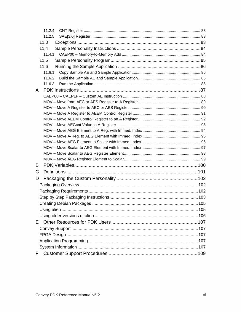
5.1 Supported Machine State
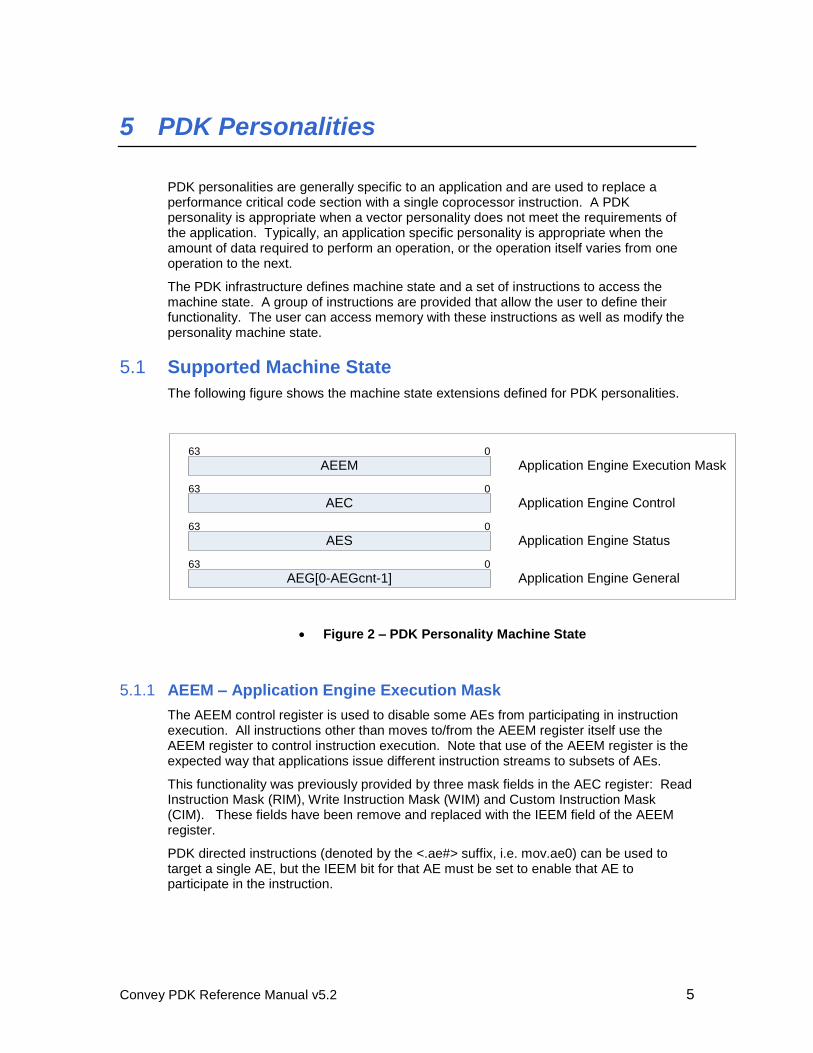
The following figure shows the machine state extensions defined for PDK personalities.
AEG[0-AEGcnt-1]0
Application Engine General63
AEEM Application Engine Execution Mask
AEC Application Engine Control063
063
AES Application Engine Status063
Figure 2 – PDK Personality Machine State
5.1.1 AEEM – Application Engine Execution Mask
The AEEM control register is used to disable some AEs from participating in instruction execution. All instructions other than moves to/from the AEEM register itself use the AEEM register to control instruction execution. Note that use of the AEEM register is the expected way that applications issue different instruction streams to subsets of AEs.
This functionality was previously provided by three mask fields in the AEC register: Read Instruction Mask (RIM), Write Instruction Mask (WIM) and Custom Instruction Mask (CIM). These fields have been remove and replaced with the IEEM field of the AEEM register.
PDK directed instructions (denoted by the <.ae#> suffix, i.e. mov.ae0) can be used to target a single AE, but the IEEM bit for that AE must be set to enable that AE to participate in the instruction.
Convey PDK Reference Manual v5.2 6
0
IEEM
63 15
Rsvd
Figure 3 – AEEM Control Register Format
The fields of the AEEM register are defined in the following table.
Field Name
Bit Range Description
IEEM 15:0 The Instruction Execution Enable Mask field specifies which application engines are to participate in instruction execution. Bit zero when set to a one enables application engine #0, bit one enables AE #1, etc.
Table 1 – AEEM Register Fields
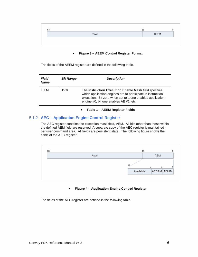
5.1.2 AEC – Application Engine Control Register
The AEC register contains the exception mask field, AEM. All bits other than those within the defined AEM field are reserved. A separate copy of the AEC register is maintained per user command area. All fields are persistent state. The following figure shows the fields of the AEC register.
0
AEM
63 15
Rsvd
Available AEUIM
015
1
AEERM
2
Figure 4 – Application Engine Control Register
The fields of the AEC register are defined in the following table.
Convey PDK Reference Manual v5.2 7
Field Name Bit Range Description
AEM 15:0 The Application Engine Mask specifies which exceptions are to be masked (i.e. ignored by the coprocessor). Exceptions with their mask set to one are ignored.
Table 2 – AEC Register Fields
Refer to section 5.1.3 for a description of each exception type.
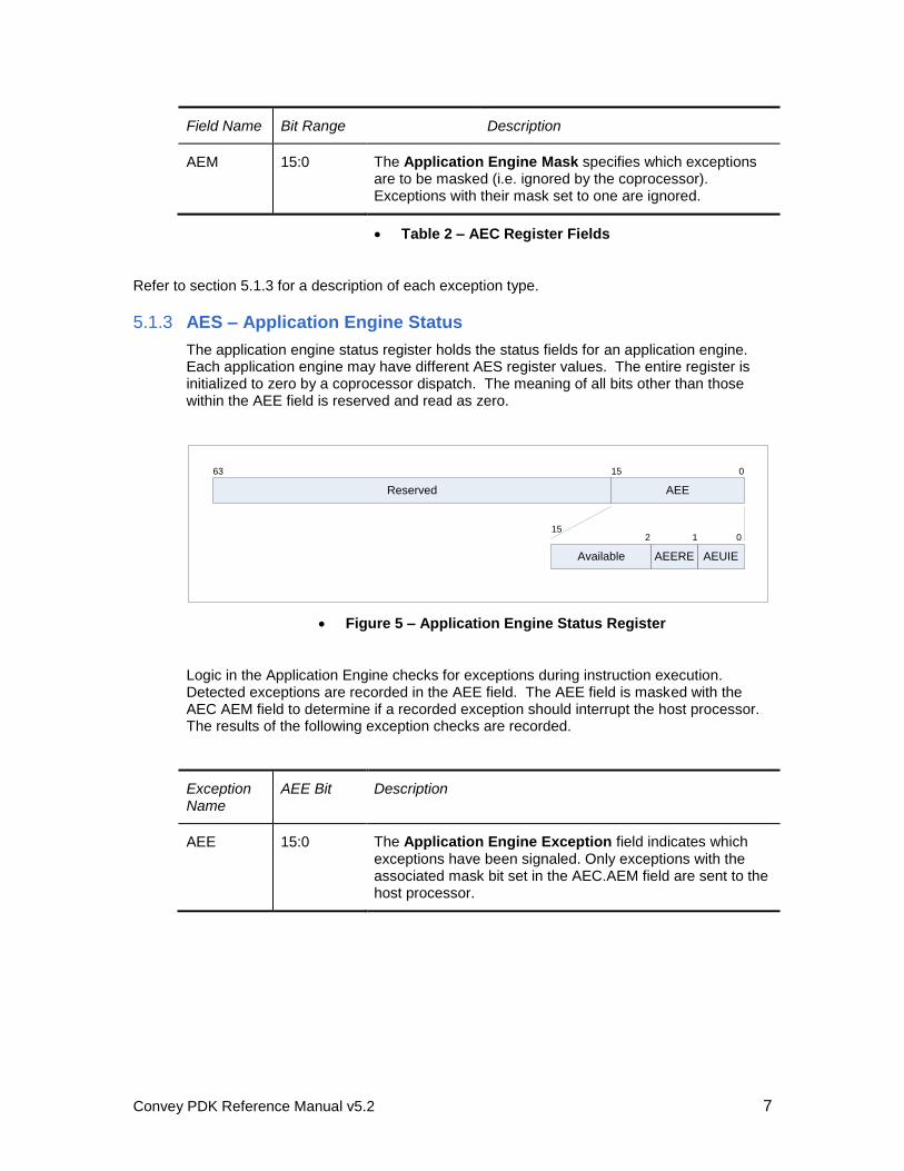
5.1.3 AES – Application Engine Status
The application engine status register holds the status fields for an application engine. Each application engine may have different AES register values. The entire register is initialized to zero by a coprocessor dispatch. The meaning of all bits other than those within the AEE field is reserved and read as zero.
0
AEE
63
Reserved
15
Available AEUIE
015
1
AEERE
2
Figure 5 – Application Engine Status Register
Logic in the Application Engine checks for exceptions during instruction execution. Detected exceptions are recorded in the AEE field. The AEE field is masked with the AEC AEM field to determine if a recorded exception should interrupt the host processor. The results of the following exception checks are recorded.
Exception Name
AEE Bit Description
AEE 15:0 The Application Engine Exception field indicates which exceptions have been signaled. Only exceptions with the associated mask bit set in the AEC.AEM field are sent to the host processor.
Convey PDK Reference Manual v5.2 8
Exception Name
AEE Bit Description
AEUIE 0 AE Unimplemented Instruction Exception. An attempt was made to execute an unimplemented instruction. The operation of the unimplemented instruction depends on the value of the instruction’s opcode. If the opcode is in a range of opcodes that is defined to return a value to the AEH then the value zero is returned; otherwise the instruction is equivalent to a NOP.
AEERE 1 AE Element Range Exception. An instruction referenced an AEG register where the element index value exceeded the valid range.
1:0 Reserved for PDK use.
15:2 Available for specific PDK use. A PDK may define additional exceptions.
Table 3 – AES Register Fields
5.1.4 AEG Register
The AEG register is a single register with multiple elements (AEGcnt). Each element is 64-bits in size. The PDK ISA defines instructions that access the AEG register as a single one-dimensional structure. The PDK personality may subdivide the AEG register elements as needed, with each subset organized as multi-dimensional structures as appropriate for the customer algorithm being defined.
The AEG register is non-persistent state.
5.2 Context Save and Restore
The PDK ISA defines the mechanism that context is saved / restored from memory. Context is saved / restored when a break point is reached when using a debugger. Additionally, context is saved in the form of a process core file when an unmasked exception is detected.
The state saved / restored for PDK personalities includes the AEC, AES and AEG registers. The instruction ‘MOV AEGcnt,At’ is used to obtain the number of elements contained within the AEG register for each PDK personality.
5.3 PDK Instruction Set Architecture
The PDK instruction set extensions contain the following classes of instructions:
Moves to/from Scalar ISA machine state to PDK ISA machine state
Custom AE instructions
Convey PDK Reference Manual v5.2 9
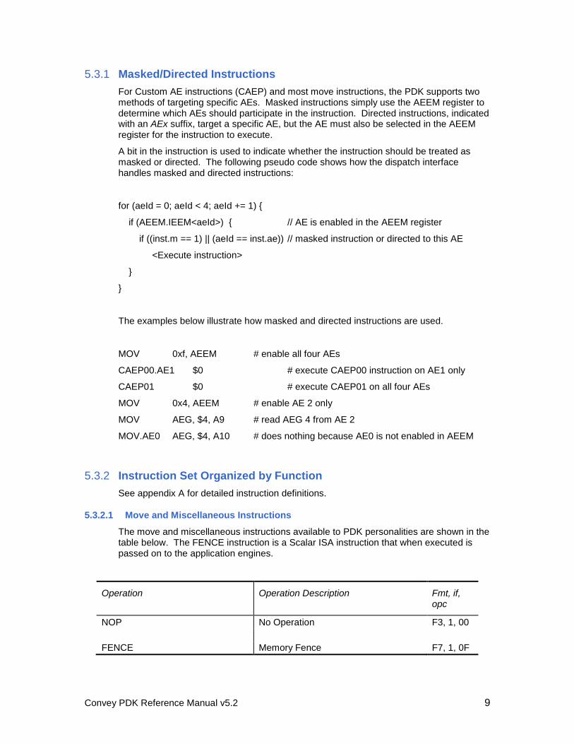
5.3.1 Masked/Directed Instructions
For Custom AE instructions (CAEP) and most move instructions, the PDK supports two methods of targeting specific AEs. Masked instructions simply use the AEEM register to determine which AEs should participate in the instruction. Directed instructions, indicated with an AEx suffix, target a specific AE, but the AE must also be selected in the AEEM register for the instruction to execute.
A bit in the instruction is used to indicate whether the instruction should be treated as masked or directed. The following pseudo code shows how the dispatch interface handles masked and directed instructions:
for (aeId = 0; aeId < 4; aeId += 1) {
if (AEEM.IEEM<aeId>) { // AE is enabled in the AEEM register
if ((inst.m == 1) || (aeId == inst.ae)) // masked instruction or directed to this AE
<Execute instruction>
}
}
The examples below illustrate how masked and directed instructions are used.
MOV 0xf, AEEM # enable all four AEs
CAEP00.AE1 $0 # execute CAEP00 instruction on AE1 only
CAEP01 $0 # execute CAEP01 on all four AEs
MOV 0x4, AEEM # enable AE 2 only
MOV AEG, $4, A9 # read AEG 4 from AE 2
MOV.AE0 AEG, $4, A10 # does nothing because AE0 is not enabled in AEEM
5.3.2 Instruction Set Organized by Function
See appendix A for detailed instruction definitions.
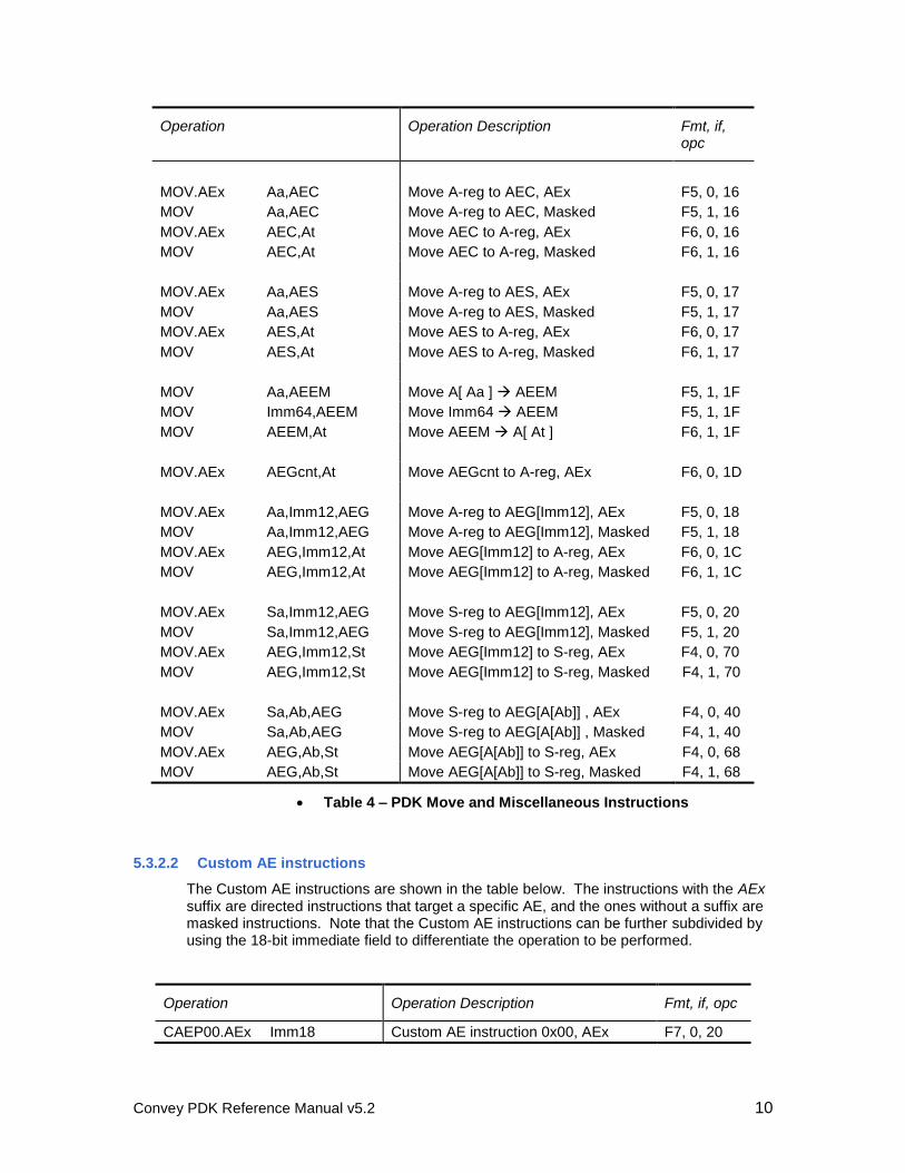
5.3.2.1 Move and Miscellaneous Instructions
The move and miscellaneous instructions available to PDK personalities are shown in the table below. The FENCE instruction is a Scalar ISA instruction that when executed is passed on to the application engines.
Operation Operation Description Fmt, if, opc
NOP No Operation F3, 1, 00
FENCE Memory Fence F7, 1, 0F
Convey PDK Reference Manual v5.2 10
Operation Operation Description Fmt, if, opc
MOV.AEx Aa,AEC Move A-reg to AEC, AEx F5, 0, 16
MOV Aa,AEC Move A-reg to AEC, Masked F5, 1, 16
MOV.AEx AEC,At Move AEC to A-reg, AEx F6, 0, 16
MOV AEC,At Move AEC to A-reg, Masked F6, 1, 16
MOV.AEx Aa,AES Move A-reg to AES, AEx F5, 0, 17
MOV Aa,AES Move A-reg to AES, Masked F5, 1, 17
MOV.AEx AES,At Move AES to A-reg, AEx F6, 0, 17
MOV AES,At Move AES to A-reg, Masked F6, 1, 17
MOV Aa,AEEM Move A[ Aa ] AEEM F5, 1, 1F
MOV Imm64,AEEM Move Imm64 AEEM F5, 1, 1F
MOV AEEM,At Move AEEM A[ At ] F6, 1, 1F
MOV.AEx AEGcnt,At Move AEGcnt to A-reg, AEx F6, 0, 1D
MOV.AEx Aa,Imm12,AEG Move A-reg to AEG[Imm12], AEx F5, 0, 18
MOV Aa,Imm12,AEG Move A-reg to AEG[Imm12], Masked F5, 1, 18
MOV.AEx AEG,Imm12,At Move AEG[Imm12] to A-reg, AEx F6, 0, 1C
MOV AEG,Imm12,At Move AEG[Imm12] to A-reg, Masked F6, 1, 1C
MOV.AEx Sa,Imm12,AEG Move S-reg to AEG[Imm12], AEx F5, 0, 20
MOV Sa,Imm12,AEG Move S-reg to AEG[Imm12], Masked F5, 1, 20
MOV.AEx AEG,Imm12,St Move AEG[Imm12] to S-reg, AEx F4, 0, 70
MOV AEG,Imm12,St Move AEG[Imm12] to S-reg, Masked F4, 1, 70
MOV.AEx Sa,Ab,AEG Move S-reg to AEG[A[Ab]] , AEx F4, 0, 40
MOV Sa,Ab,AEG Move S-reg to AEG[A[Ab]] , Masked F4, 1, 40
MOV.AEx AEG,Ab,St Move AEG[A[Ab]] to S-reg, AEx F4, 0, 68
MOV AEG,Ab,St Move AEG[A[Ab]] to S-reg, Masked F4, 1, 68
Table 4 – PDK Move and Miscellaneous Instructions
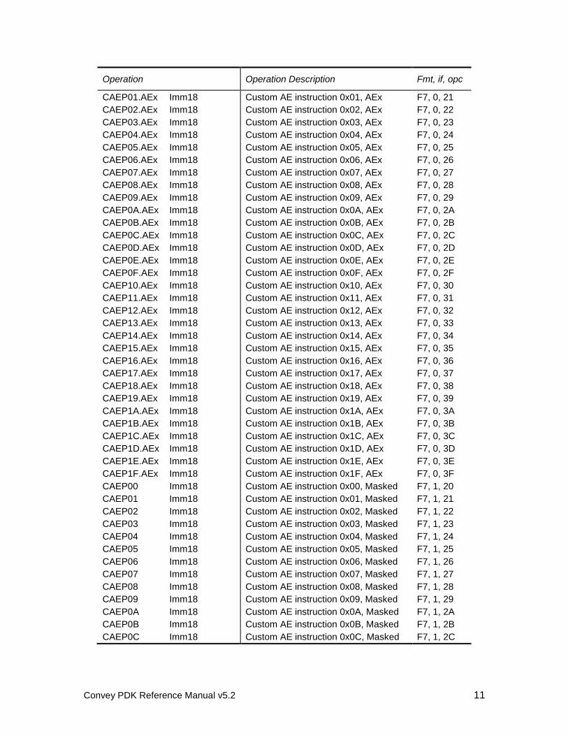
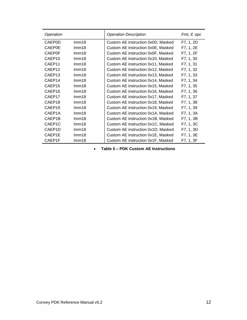
5.3.2.2 Custom AE instructions
The Custom AE instructions are shown in the table below. The instructions with the AEx suffix are directed instructions that target a specific AE, and the ones without a suffix are masked instructions. Note that the Custom AE instructions can be further subdivided by using the 18-bit immediate field to differentiate the operation to be performed.
Operation Operation Description Fmt, if, opc
CAEP00.AEx Imm18 Custom AE instruction 0x00, AEx F7, 0, 20
Convey PDK Reference Manual v5.2 11
Operation Operation Description Fmt, if, opc
CAEP01.AEx Imm18 Custom AE instruction 0x01, AEx F7, 0, 21 CAEP02.AEx Imm18 Custom AE instruction 0x02, AEx F7, 0, 22 CAEP03.AEx Imm18 Custom AE instruction 0x03, AEx F7, 0, 23 CAEP04.AEx Imm18 Custom AE instruction 0x04, AEx F7, 0, 24 CAEP05.AEx Imm18 Custom AE instruction 0x05, AEx F7, 0, 25 CAEP06.AEx Imm18 Custom AE instruction 0x06, AEx F7, 0, 26 CAEP07.AEx Imm18 Custom AE instruction 0x07, AEx F7, 0, 27 CAEP08.AEx Imm18 Custom AE instruction 0x08, AEx F7, 0, 28 CAEP09.AEx Imm18 Custom AE instruction 0x09, AEx F7, 0, 29 CAEP0A.AEx Imm18 Custom AE instruction 0x0A, AEx F7, 0, 2A CAEP0B.AEx Imm18 Custom AE instruction 0x0B, AEx F7, 0, 2B CAEP0C.AEx Imm18 Custom AE instruction 0x0C, AEx F7, 0, 2C CAEP0D.AEx Imm18 Custom AE instruction 0x0D, AEx F7, 0, 2D CAEP0E.AEx Imm18 Custom AE instruction 0x0E, AEx F7, 0, 2E CAEP0F.AEx Imm18 Custom AE instruction 0x0F, AEx F7, 0, 2F CAEP10.AEx Imm18 Custom AE instruction 0x10, AEx F7, 0, 30 CAEP11.AEx Imm18 Custom AE instruction 0x11, AEx F7, 0, 31 CAEP12.AEx Imm18 Custom AE instruction 0x12, AEx F7, 0, 32 CAEP13.AEx Imm18 Custom AE instruction 0x13, AEx F7, 0, 33 CAEP14.AEx Imm18 Custom AE instruction 0x14, AEx F7, 0, 34 CAEP15.AEx Imm18 Custom AE instruction 0x15, AEx F7, 0, 35 CAEP16.AEx Imm18 Custom AE instruction 0x16, AEx F7, 0, 36 CAEP17.AEx Imm18 Custom AE instruction 0x17, AEx F7, 0, 37 CAEP18.AEx Imm18 Custom AE instruction 0x18, AEx F7, 0, 38 CAEP19.AEx Imm18 Custom AE instruction 0x19, AEx F7, 0, 39 CAEP1A.AEx Imm18 Custom AE instruction 0x1A, AEx F7, 0, 3A CAEP1B.AEx Imm18 Custom AE instruction 0x1B, AEx F7, 0, 3B CAEP1C.AEx Imm18 Custom AE instruction 0x1C, AEx F7, 0, 3C CAEP1D.AEx Imm18 Custom AE instruction 0x1D, AEx F7, 0, 3D CAEP1E.AEx Imm18 Custom AE instruction 0x1E, AEx F7, 0, 3E CAEP1F.AEx Imm18 Custom AE instruction 0x1F, AEx F7, 0, 3F CAEP00 Imm18 Custom AE instruction 0x00, Masked F7, 1, 20 CAEP01 Imm18 Custom AE instruction 0x01, Masked F7, 1, 21 CAEP02 Imm18 Custom AE instruction 0x02, Masked F7, 1, 22 CAEP03 Imm18 Custom AE instruction 0x03, Masked F7, 1, 23 CAEP04 Imm18 Custom AE instruction 0x04, Masked F7, 1, 24 CAEP05 Imm18 Custom AE instruction 0x05, Masked F7, 1, 25 CAEP06 Imm18 Custom AE instruction 0x06, Masked F7, 1, 26 CAEP07 Imm18 Custom AE instruction 0x07, Masked F7, 1, 27 CAEP08 Imm18 Custom AE instruction 0x08, Masked F7, 1, 28 CAEP09 Imm18 Custom AE instruction 0x09, Masked F7, 1, 29 CAEP0A Imm18 Custom AE instruction 0x0A, Masked F7, 1, 2A CAEP0B Imm18 Custom AE instruction 0x0B, Masked F7, 1, 2B CAEP0C Imm18 Custom AE instruction 0x0C, Masked F7, 1, 2C
Convey PDK Reference Manual v5.2 12
Operation Operation Description Fmt, if, opc
CAEP0D Imm18 Custom AE instruction 0x0D, Masked F7, 1, 2D CAEP0E Imm18 Custom AE instruction 0x0E, Masked F7, 1, 2E CAEP0F Imm18 Custom AE instruction 0x0F, Masked F7, 1, 2F CAEP10 Imm18 Custom AE instruction 0x10, Masked F7, 1, 30 CAEP11 Imm18 Custom AE instruction 0x11, Masked F7, 1, 31 CAEP12 Imm18 Custom AE instruction 0x12, Masked F7, 1, 32 CAEP13 Imm18 Custom AE instruction 0x13, Masked F7, 1, 33 CAEP14 Imm18 Custom AE instruction 0x14, Masked F7, 1, 34 CAEP15 Imm18 Custom AE instruction 0x15, Masked F7, 1, 35 CAEP16 Imm18 Custom AE instruction 0x16, Masked F7, 1, 36 CAEP17 Imm18 Custom AE instruction 0x17, Masked F7, 1, 37 CAEP18 Imm18 Custom AE instruction 0x18, Masked F7, 1, 38 CAEP19 Imm18 Custom AE instruction 0x19, Masked F7, 1, 39 CAEP1A Imm18 Custom AE instruction 0x1A, Masked F7, 1, 3A CAEP1B Imm18 Custom AE instruction 0x1B, Masked F7, 1, 3B CAEP1C Imm18 Custom AE instruction 0x1C, Masked F7, 1, 3C CAEP1D Imm18 Custom AE instruction 0x1D, Masked F7, 1, 3D CAEP1E Imm18 Custom AE instruction 0x1E, Masked F7, 1, 3E CAEP1F Imm18 Custom AE instruction 0x1F, Masked F7, 1, 3F
Table 5 – PDK Custom AE Instructions
Convey PDK Reference Manual v5.2 13
6 PDK Development Steps
This chapter contains step-by-step instructions for the process of developing a custom personality for the Convey Coprocessor.
6.1 Analyze Application
The first step of personality development is to completely understand the problem to be solved. How does the current application perform on existing hardware? What bottlenecks are limiting the performance? What data structures are involved? How parallelizable is the application?
Answers to these questions provide the first insight into how the application can be accelerated in hardware. Some tools that are useful in gathering this information are gprof (The GNU Profiler) and oprofile.
6.2 Evaluate Hardware Options
With a detailed knowledge of the application and its performance limitations, the second step is to evaluate options for implementing the application in hardware. This requires a good understanding of the hardware architecture and the FPGA resources available to the custom personality.
Once a concept for hardware design is completed, the performance of the hardware can be compared relative to the existing application performance.
6.3 Define Custom Instructions
With a hardware concept in place, the functions implemented by the hardware design can then be mapped to custom instructions. These are a set of instructions in the Convey Instruction Set Architecture reserved for custom personalities. Instruction sets designed to be used across a wide variety of applications typically have a large number of instructions that perform relatively simple operations. But because a custom personality is designed to improve the performance of a single application, it might implement very few instructions with much more complex behavior.
The customs instructions available to a PDK personality are defined in section 5.3, and individual instructions are described in detail in appendix A.
6.4 Develop Software Model of Custom Personality
Convey provides an architecture simulation environment to allow rapid prototyping of both the hardware and software components of a custom personality. This environment is written in C++ to emulate the rest of the system. It includes hardware models of instruction dispatch, register state and the memory subsystem.
With a hardware design concept in place, and a definition of custom instructions to interface to that hardware, a software model can be developed to emulate the hardware. The hardware model can then be simulated with the rest of the system to prove the concept before detailed design begins.
Chapter 7 describes how to develop a software model of the custom personality.
Convey PDK Reference Manual v5.2 14
6.5 Replace Application Kernel with Call to Coprocessor
The application should be modified so that the application kernel can be called as a function. To dispatch instructions to the coprocessor, the kernel function call is replaced with a call to dispatch the function to the coprocessor. This function explicitly defines the custom instructions to be dispatched to the Application Engines. The sample application described later in this document illustrates the use of this interface.
6.6 Compile Application with Convey Compiler
The PDK package includes Convey64 compilers that can be used to compile coprocessor applications with direct calls to coprocessor functions. The sample application makefile illustrates how the code should be compiled.
6.7 Simulate Application with Convey Architecture Simulator
Once the AE software model is in place and the appropriate changes to the application have been made, the application can be run against the Convey architecture simulator. This step allows the application and the custom instruction set to be debugged before the hardware is designed.
6.8 Develop FPGA Hardware
With an instruction set architecture defined, the hardware implementation can begin. Chapter 9 of this manual describes the development steps necessary to implement a custom personality in the FPGA.
6.9 Simulate Hardware in Convey Simulation Environment
As an extension of the Convey architecture simulator, Convey provides a hardware simulation environment with bus-functional models for all hardware interfaces to the Application Engine (AE) FPGA. Using a standard VPI interface (Verilog Procedural Interface) the architecture simulator can be used to provide stimulus to the HDL simulation.
6.10 Integrate with Convey Hardware
The final step is to run the application on the Convey Coprocessor hardware.
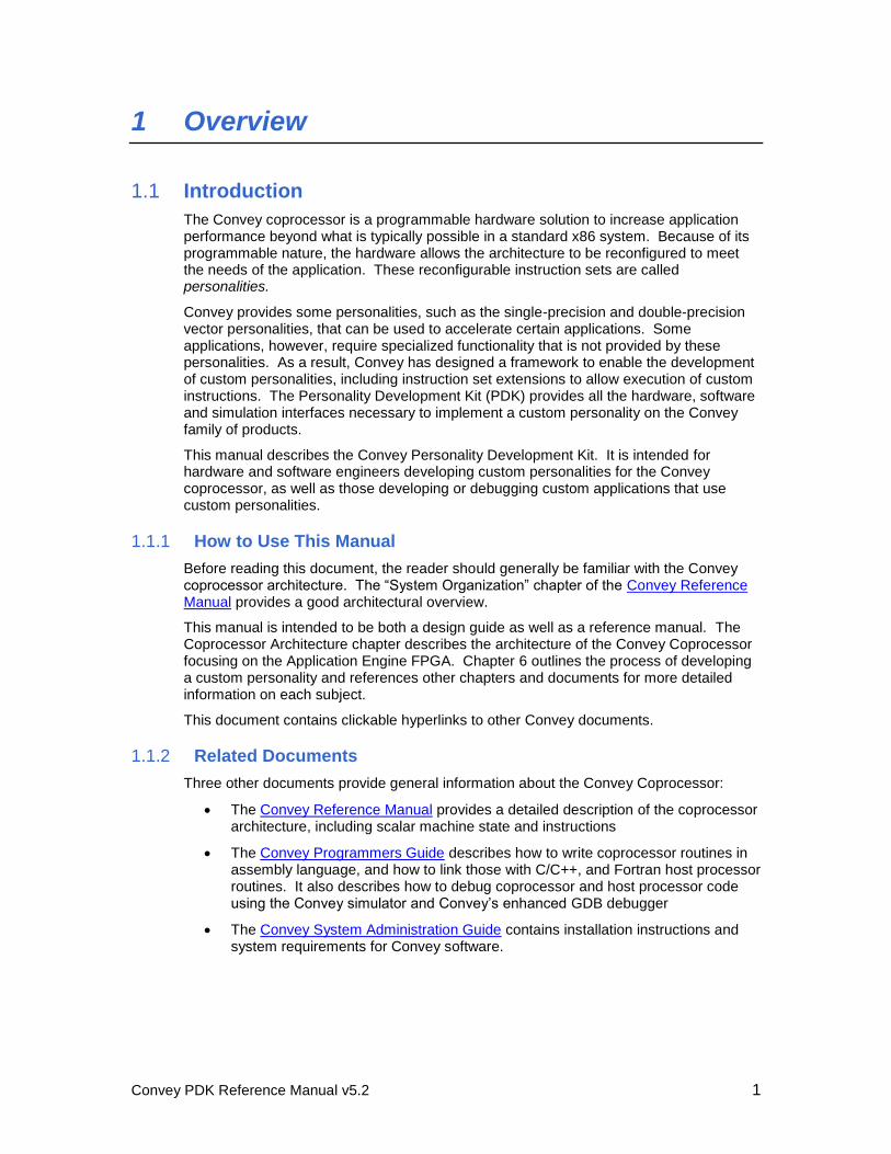
Convey PDK Reference Manual v5.2 15
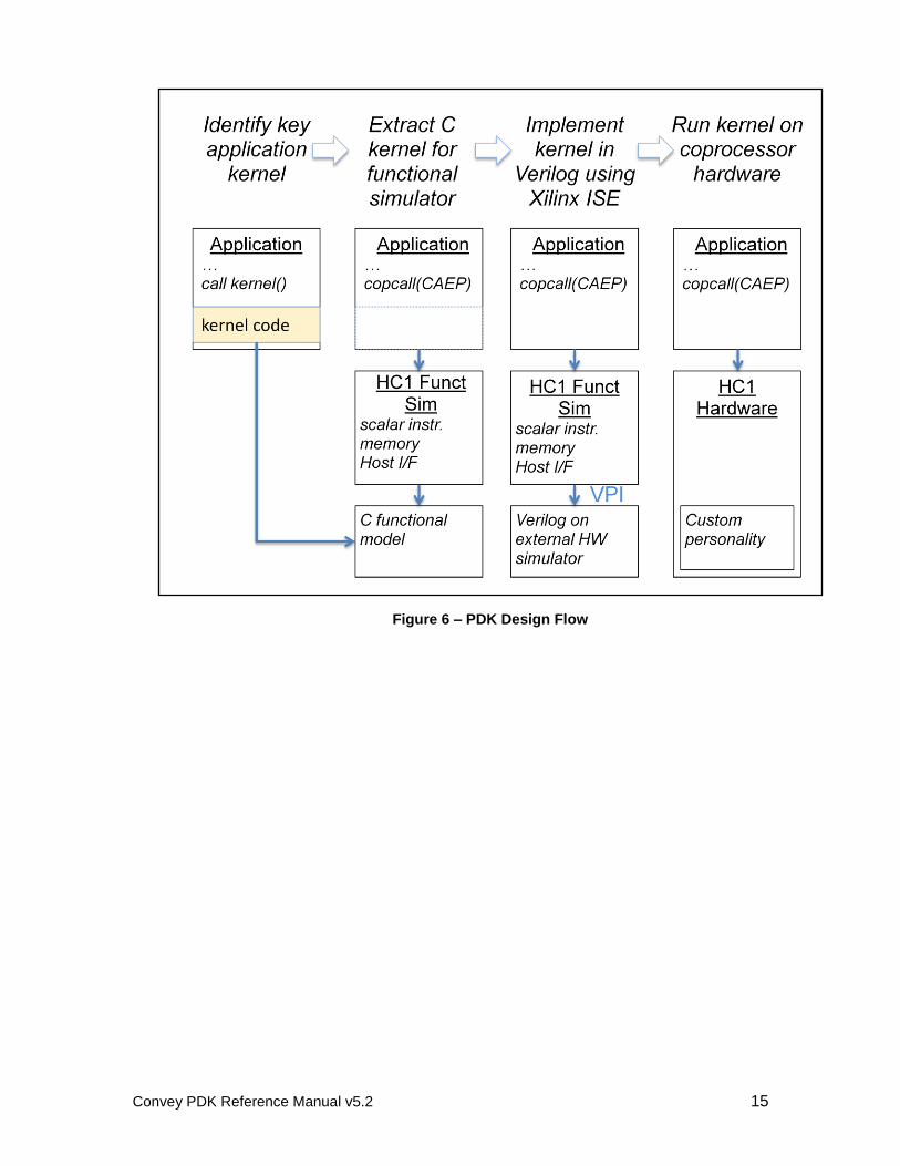
Figure 6 – PDK Design Flow
Convey PDK Reference Manual v5.2 16
7 Custom AE Software Model Development
Convey’s architecture simulator was developed to allow software to be tested and debugged in the absence of the actual Convey coprocessor hardware. It can also be used to prototype a PDK design quickly before investing the time to develop the FPGA hardware.
The simulator models the machine state and the canonical instruction set defined in Convey Reference Manual, as well as instructions for the single and double-precision vector personalities designed by Convey. For custom personalities, the instruction set extensions are defined by the customer and therefore cannot be modeled in the simulator. A socket interface is designed into the simulator to allow a customer-developed AE software model to connect to the simulation process.
7.1 Conceptual Overview of the Software Modeling Process
The application executable is a Linux executable, where host code calls to coprocessor routines are routed to the simulator. The host x86-64 code and the coprocessor simulator share the memory space of the executable, just as the real Convey coprocessor shares memory with the x86-64 host code. The Convey simulator can execute user written software emulation routines that emulate the user-defined instruction set, or use a Verilog simulator with a user developed Application Engine FPGA image. For more information on compiling applications, see the Convey Programmers Guide.
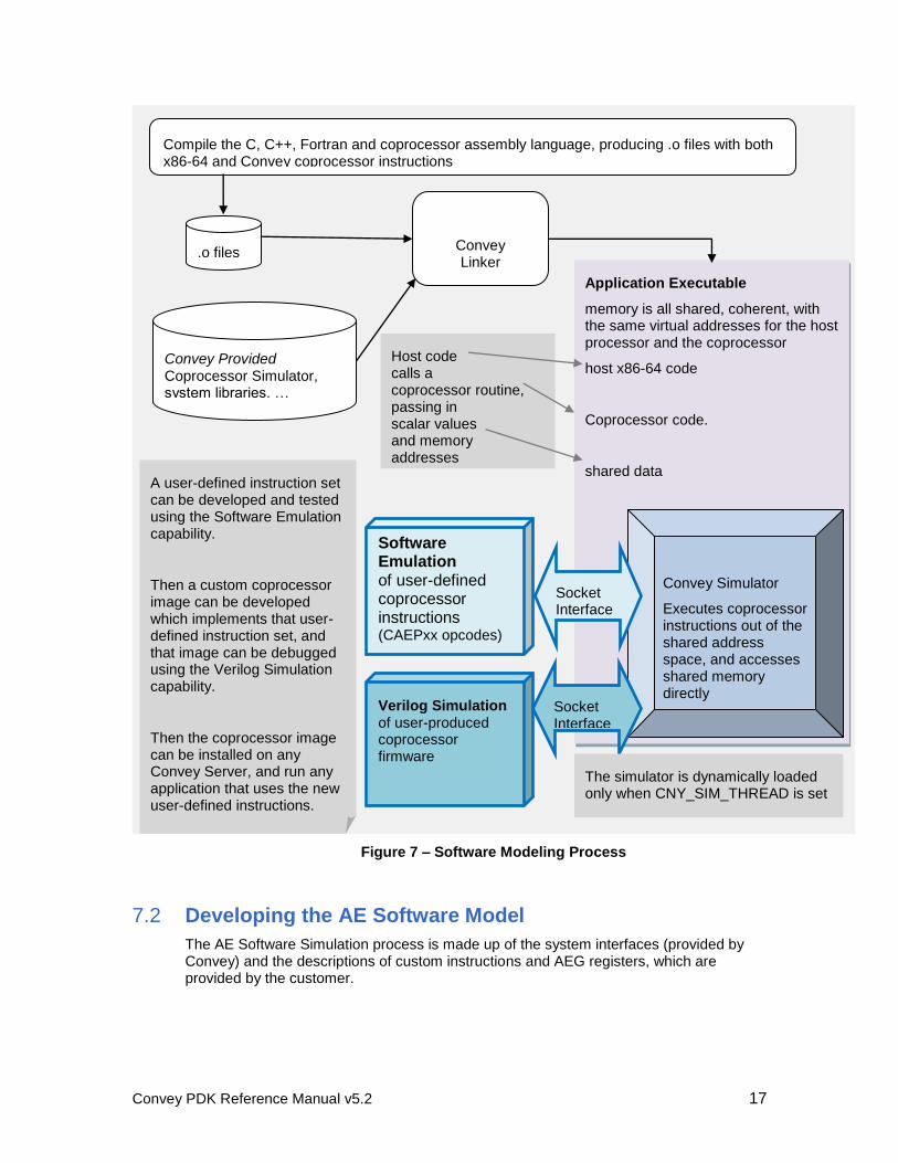
The diagram below illustrates the software modeling process used to develop custom applications.
Convey PDK Reference Manual v5.2 17
7.2 Developing the AE Software Model
The AE Software Simulation process is made up of the system interfaces (provided by Convey) and the descriptions of custom instructions and AEG registers, which are provided by the customer.
Application Executable memory is all shared, coherent, with the same virtual addresses for the host processor and the coprocessor
host x86-64 code
Coprocessor code.
shared data
Compile the C, C++, Fortran and coprocessor assembly language, producing .o files with both x86-64 and Convey coprocessor instructions
Software Emulation of user-defined coprocessor instructions (CAEPxx opcodes)
Convey Simulator
Executes coprocessor instructions out of the shared address space, and accesses shared memory directly
Convey Linker
Verilog Simulation of user-produced coprocessor firmware
Socket Interface
Socket Interface
A user-defined instruction set can be developed and tested using the Software Emulation capability.
Then a custom coprocessor image can be developed which implements that user-defined instruction set, and that image can be debugged using the Verilog Simulation capability.
Then the coprocessor image can be installed on any Convey Server, and run any application that uses the new user-defined instructions.
Host code calls a coprocessor routine, passing in scalar values and memory addresses
.o files
Convey Provided Coprocessor Simulator, system libraries, …
The simulator is dynamically loaded only when CNY_SIM_THREAD is set
Figure 7 – Software Modeling Process
Convey PDK Reference Manual v5.2 18
7.2.1 Functions implemented by Custom Personality
The software model of the custom personality must implement the following functions:
void CCaeIsa::InitPers()
void CCaeIsa::CaepInst(int masked, int ae, int opcode, int immed, uint64 scalar)
7.2.1.1 InitPers
The InitPers function is called by the architecture simulator and allows the custom personality code to set variables inside the simulator. Inside this function, the personality must call the following function to set the max AEG index used by the custom personality.
SetAegCnt(MAX_AEG_INDEX);
7.2.1.2 CaepInst
The CaepInst function is called by the architecture simulator anytime a custom AE instruction (CAEP00-CAEP1F) is called. This call models the instruction dispatch interface in the hardware, and includes as arguments all information needed by the custom personality to decode an instruction:
aeId: AE ID (0-3)
opcode: instruction opcode (0x00 – 0x3f)
immed: 18-bit immediate
inst: 32-bit instruction
data: 64-bit scalar
The customer must model all instructions implemented by the custom personality by decoding the opcode field. For opcodes that are not implemented, the function SetException(<ae>, AEUIE) must be called to assert the unimplemented instruction exception.
The complete list of functions available to the custom personality is in the next section.
7.2.2 Functions callable by Custom Personality
AeMemLoad and AeMemStore are used to load data from memory and store data to memory, respectively.
ReadAeg and WriteAeg are used to access the Application Engine General (AEG) registers in the simulation model. These registers are defined by the personality.
SetException is used to send exceptions to the architecture simulator.
SetAegCnt is used to send the simulator the number of AEG registers implemented in the personality.
7.2.2.1 AeMemLoad
Memory load requests are sent across the socket interface to the coprocessor simulator thread, which maintains memory state. A 64-bit value is returned.
bool CCaeIsa::AeMemLoad(int aeId, int mcId, uint64 addr, int size, bool bSigned, uint64 &data)

Convey PDK Reference Manual v5.2 19
int aeId is the Application Engine Identifier, which is a number from 0 to 3
indicating the index of the AE sending the request.
int mcId is the Memory Controller Identifier, which is a number from 0-7 indicating
which MC the request should be sent to. For binary interleave, which is typically
used for PDK designs, the MC is determined by bits 8:6 of the virtual address.
int size is the size of the request to the MC in bytes. Valid sizes are 1, 2, 4 and 8.
Note that the simulator expects logical size values, not encoded values as in the
FPGA signal interface.
bSigned indicates whether the data is signed (1) or unsigned (0)
unit 64 &data will contain the data loaded from memory. The data is right justified.
7.2.2.2 AeMemStore
Memory store requests are sent across the socket interface to the coprocessor simulator thread, which maintains memory state. No return value.
bool CCaeIsa::AeMemStore(int aeId, int mcId, uint64 addr, int size, bool bSigned, uint64 data)
int aeId is the Application Engine Identifier, which is a number from 0 to 3
indicating the index of the AE sending the request
int mcId is the Memory Controller Identifier, which is a number from 0-7 indicating
which MC the request should be sent to. For binary interleave, which is typically
used for PDK designs, the MC is determined by bits 8:6 of the virtual address.
int size is the size of the request to the MC in bytes. Valid sizes are 1, 2, 4 and 8.
Note that the simulator expects logical size values, not encoded values as in the
FPGA signal interface.
bSigned indicates whether the data is signed (1) or unsigned (0).
unit 64 &data contain the data to be stored to memory. The data is right justified
7.2.2.3 ReadAeg
Read a 64-bit AEG register.
uint64 CCaeIsa::ReadAeg(int aeId, int aegIdx)
int aeId is the Application Engine Identifier, which is a number from 0 to 3
indicating the index of the AE sending the request.
int aegIdx is the index of the AEG to be read or written.
7.2.2.4 WriteAeg
Write a 64-bit AEG register.
void CCaeIsa::WriteAeg(int aeId, int aegIdx, uint64 data)
int aeId is the Application Engine Identifier, which is a number from 0 to 3
indicating the index of the AE sending the request.
int aegIdx is the index of the AEG to be read or written.
unit64 data is the data to be written into the AEG
Convey PDK Reference Manual v5.2 20
7.2.2.5 SetException
Exceptions defined by the custom personality can be set by calling SetException with an integer value of the exception bit number. For instance, an unimplemented instruction exception (AEUIE, defined in section 5.1.3) can be set by calling
void CCaeIsa::SetException(int aeId, int bitNum)
int aeId is the Application Engine Identifier, which is a number from 0 to 3
indicating the index of the AE sending the request.
int bitNum is the bit number of the exception bus to set. Setting bitNum to 4 sets
bit 4 of the bus.
7.2.2.6 SetAegCnt
The AEGCnt defines the maximum AEG register index used in the custom personality. This value is used by GDB for context save and restore. The custom personality software model must call this function in the InitPers() routine to set AEGCnt appropriately.
void CCaeIsa::SetAegCnt(int AegCnt)
7.3 Compiling the Model
The AE software model is compiled into an executable using the source code for the custom personality and the Convey-supplied libraries. This executable is automatically run by the Convey architecture simulator when an application is run on the architecture simulator and dispatches a PDK personality. The software model is also compiled into a shared library to be used in the Verilog simulation.
Convey PDK Reference Manual v5.2 21
8 Application Development/Modification
8.1 Add Coprocessor Function Calls to Application
The Convey runtime libraries provide an interface to allow the programmer to make coprocessor calls directly from the application. This interface is defined in the Convey Programmers Guide.
The PDK includes a sample application that illustrates how to use the application interfaces to the coprocessor.
8.2 Running the Application on the Architecture Simulator
Running the application on the simulator requires two environment variables to be correctly defined. The CNY_SIM_THREAD variable should be set to ”libcpSimLib2.so “, and the CNY_CAE_EMULATOR variable should have the path to the AE simulator model. See section 11.6 for information on setting these variables to run the sample application.
8.3 Debug Application with GDB
Convey provides a version of the GDB debugger to use in debugging x-86 and coprocessor routines. This debugger has been extended with coprocessor-specific register state. Before debugging a coprocessor application with GDB, make sure that the Convey-supplied GDB is running (rather than the GDB supplied with the Linux distribution). Use /opt/convey/bin/gdb, or type `which gdb` to make sure
Convey’s GDB is first in the path. See the Convey System Administration Guide for details on software install and setup.
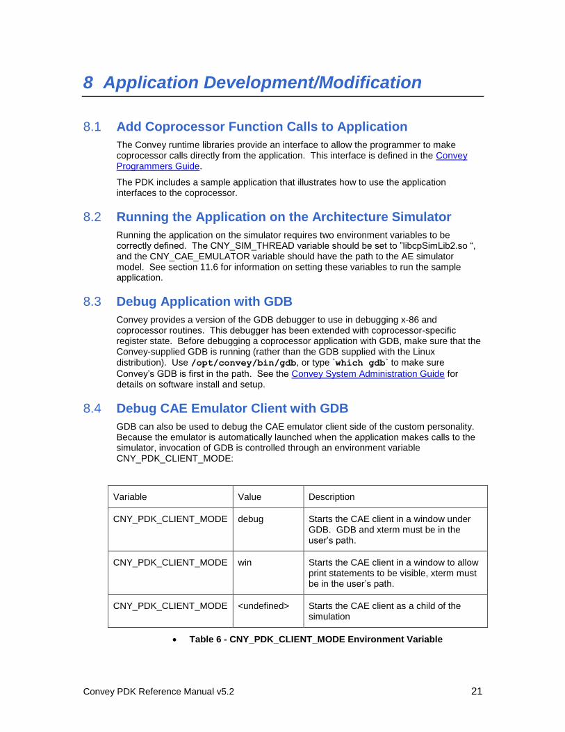
8.4 Debug CAE Emulator Client with GDB
GDB can also be used to debug the CAE emulator client side of the custom personality. Because the emulator is automatically launched when the application makes calls to the simulator, invocation of GDB is controlled through an environment variable CNY_PDK_CLIENT_MODE:
Variable Value Description
CNY_PDK_CLIENT_MODE debug Starts the CAE client in a window under GDB. GDB and xterm must be in the user’s path.
CNY_PDK_CLIENT_MODE win Starts the CAE client in a window to allow print statements to be visible, xterm must be in the user’s path.
CNY_PDK_CLIENT_MODE <undefined> Starts the CAE client as a child of the simulation
Table 6 - CNY_PDK_CLIENT_MODE Environment Variable
Convey PDK Reference Manual v5.2 22
8.5 Defining AEG Registers for use within GDB
Convey’s enhanced GDB debugger can be used for debugging C, C++, and Fortran code that runs on the host processor. GDB allows the user to display and modify the AEG registers directly using the register name AEG[0->3]e[0->Aeg_Cnt-1] (example aeg2e44 accesses AEG unit 2 register element 44). The user may also display the AEG registers of an AE unit using the command info cny_aeg ae_unit [first_element
[last_element]]. The default display type of these registers is long long int. In many
cases it would be beneficial to be able to display a register in a format that represents the actual usage of the register. The Convey enhanced GDB debugger will attempt to read a personality register description file that describes the AEG registers any time GDB stops and a custom personality is currently loaded in the AE. The personality register description file is attached to the personality by placing the file in the personality database folder in /opt/convey/personalities. See chapter 10 for details about setting up the personality.
8.5.1 Personality Register Description File
The personality register description file is an ASCII file that contains commands that describe a register, range of registers or the default description. The register description must be one of six types:
u64 – unsigned long long int
s64 – signed long long int
dpf – double precision float
spf – single precision float array (f[0] and f[1])
Bitfield – single bits or groups of bits may be described (similar to c and
c++ bitfields)
Union – a union of the above types (similar to c and c++ unions)
8.5.2 Built In and User Defined Descriptions
The personality register description recognizes four built in descriptions, u64, s64, dps and spf. The personality register description allows the user to construct two basic types, bitfield and union.
8.5.3 Bitfield Definitions
The definition of a bitfield starts with the BITFIELD_type_start command:
BITFIELD_type_start name_of_bitfield_type
Followed by up to 64 BITFIELD_desc commands (bit positions are numbered 0-63 where 0=lsb):
BITFIELD_desc name_of_bitfield beginning_bit number_of_bits
Followed by the BITFIELD_type_end command:
BITFIELD_type_end
Convey PDK Reference Manual v5.2 23
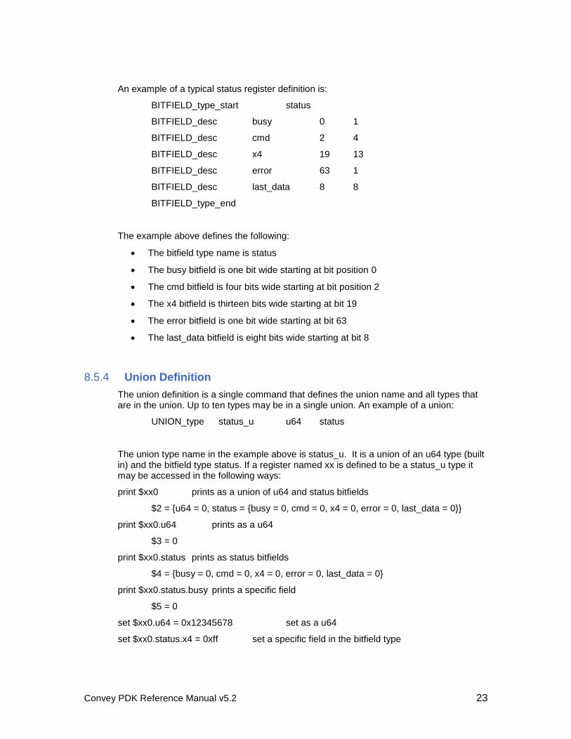
An example of a typical status register definition is:
BITFIELD_type_start status
BITFIELD_desc busy 0 1
BITFIELD_desc cmd 2 4
BITFIELD_desc x4 19 13
BITFIELD_desc error 63 1
BITFIELD_desc last_data 8 8
BITFIELD_type_end
The example above defines the following:
The bitfield type name is status
The busy bitfield is one bit wide starting at bit position 0
The cmd bitfield is four bits wide starting at bit position 2
The x4 bitfield is thirteen bits wide starting at bit 19
The error bitfield is one bit wide starting at bit 63
The last_data bitfield is eight bits wide starting at bit 8
8.5.4 Union Definition
The union definition is a single command that defines the union name and all types that are in the union. Up to ten types may be in a single union. An example of a union:
UNION_type status_u u64 status
The union type name in the example above is status_u. It is a union of an u64 type (built in) and the bitfield type status. If a register named xx is defined to be a status_u type it may be accessed in the following ways:
print $xx0 prints as a union of u64 and status bitfields
$2 = {u64 = 0, status = {busy = 0, cmd = 0, x4 = 0, error = 0, last_data = 0}}
print $xx0.u64 prints as a u64
$3 = 0
print $xx0.status prints as status bitfields
$4 = {busy = 0, cmd = 0, x4 = 0, error = 0, last_data = 0}
print $xx0.status.busy prints a specific field
$5 = 0
set $xx0.u64 = 0x12345678 set as a u64
set $xx0.status.x4 = 0xff set a specific field in the bitfield type
Convey PDK Reference Manual v5.2 24
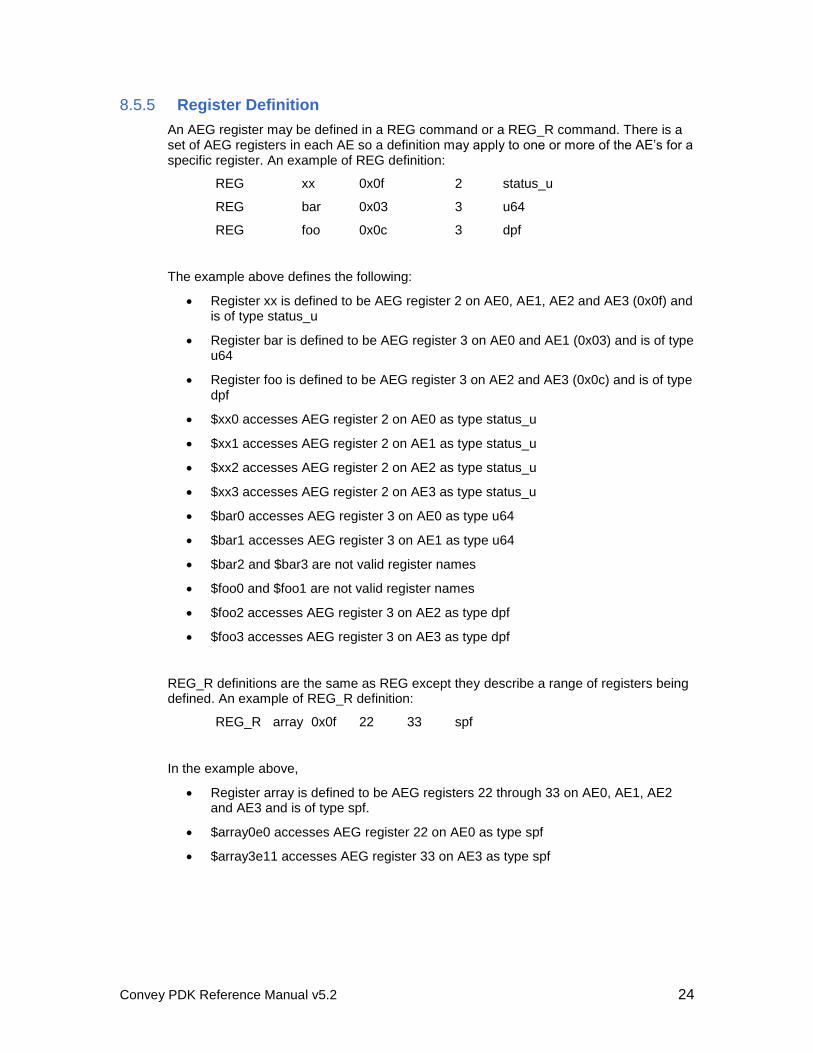
8.5.5 Register Definition
An AEG register may be defined in a REG command or a REG_R command. There is a set of AEG registers in each AE so a definition may apply to one or more of the AE’s for a specific register. An example of REG definition:
REG xx 0x0f 2 status_u
REG bar 0x03 3 u64
REG foo 0x0c 3 dpf
The example above defines the following:
Register xx is defined to be AEG register 2 on AE0, AE1, AE2 and AE3 (0x0f) and is of type status_u
Register bar is defined to be AEG register 3 on AE0 and AE1 (0x03) and is of type u64
Register foo is defined to be AEG register 3 on AE2 and AE3 (0x0c) and is of type dpf
$xx0 accesses AEG register 2 on AE0 as type status_u
$xx1 accesses AEG register 2 on AE1 as type status_u
$xx2 accesses AEG register 2 on AE2 as type status_u
$xx3 accesses AEG register 2 on AE3 as type status_u
$bar0 accesses AEG register 3 on AE0 as type u64
$bar1 accesses AEG register 3 on AE1 as type u64
$bar2 and $bar3 are not valid register names
$foo0 and $foo1 are not valid register names
$foo2 accesses AEG register 3 on AE2 as type dpf
$foo3 accesses AEG register 3 on AE3 as type dpf
REG_R definitions are the same as REG except they describe a range of registers being defined. An example of REG_R definition:
REG_R array 0x0f 22 33 spf
In the example above,
Register array is defined to be AEG registers 22 through 33 on AE0, AE1, AE2 and AE3 and is of type spf.
$array0e0 accesses AEG register 22 on AE0 as type spf
$array3e11 accesses AEG register 33 on AE3 as type spf
Convey PDK Reference Manual v5.2 25
The REG_D definition defines the type to use for all AEG registers that are not defined by REG and REG_R definitions. If the REG_D definition is not used, all undefined AEG registers default to u65.
REG_D spf
All registers not defined by REG and REG_R are of type spf.
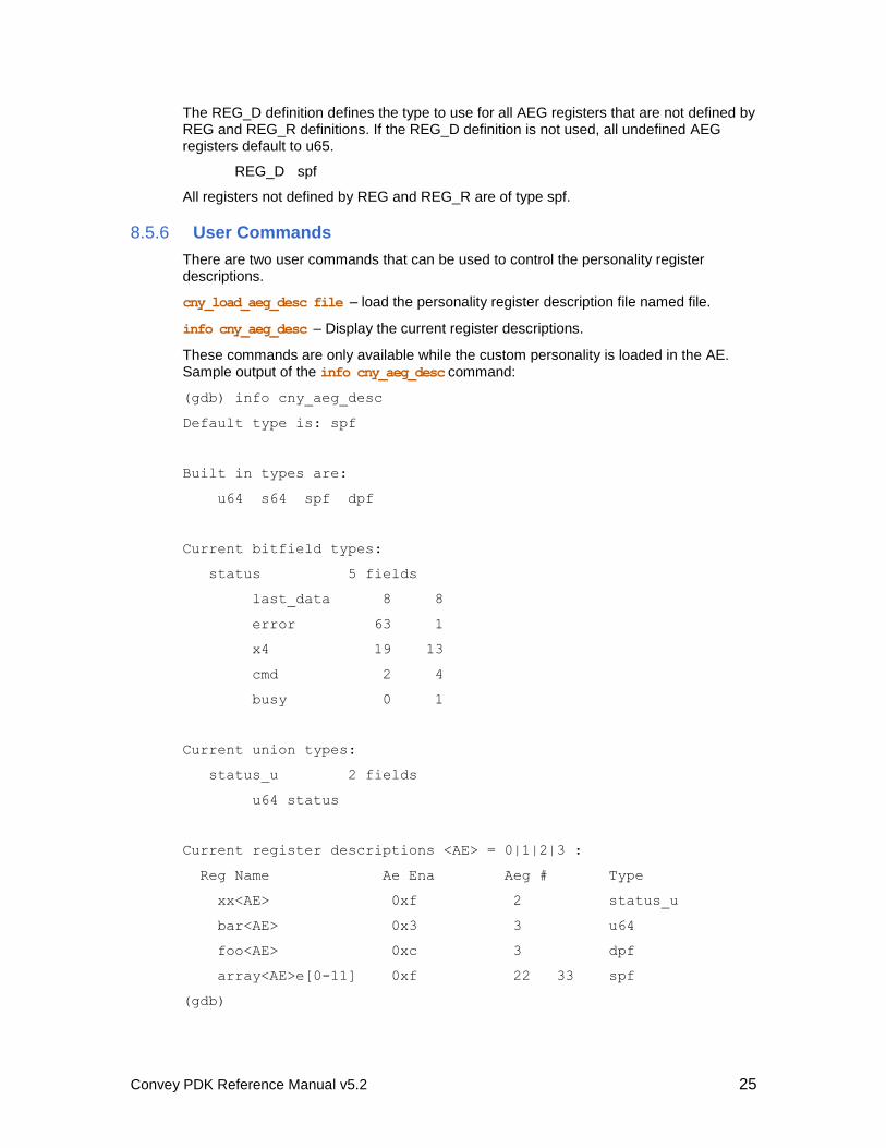
8.5.6 User Commands
There are two user commands that can be used to control the personality register descriptions.
cny_load_aeg_desc file – load the personality register description file named file.
info cny_aeg_desc – Display the current register descriptions.
These commands are only available while the custom personality is loaded in the AE. Sample output of the info cny_aeg_desc command:
(gdb) info cny_aeg_desc
Default type is: spf
Built in types are:
u64 s64 spf dpf
Current bitfield types:
status 5 fields
last_data 8 8
error 63 1
x4 19 13
cmd 2 4
busy 0 1
Current union types:
status_u 2 fields
u64 status
Current register descriptions <AE> = 0|1|2|3 :
Reg Name Ae Ena Aeg # Type
xx<AE> 0xf 2 status_u
bar<AE> 0x3 3 u64
foo<AE> 0xc 3 dpf
array<AE>e[0-11] 0xf 22 33 spf
(gdb)
Convey PDK Reference Manual v5.2 26
9 FPGA Development
9.1 Introduction
The custom personality hardware is implemented in the Application Engine (AE) FPGAs on the Convey coprocessor. This chapter describes the FPGA development process.
9.2 FPGA Technology
The PDK supports development for the HC-1, HC-2, HC-1ex and HC-2ex platforms. The Convey coprocessor uses the following FPGAs for the Application Engine FPGAs:
HC-1 / HC-2: Xilinx Virtex 5 LX330, FF1760 package
HC-1ex / HC-2ex: Xilinx Virtex 6 LX760, FF1760 package
More information about the FPGA technology is available at Xilinx.
9.3 Hardware Interfaces
The hardware interfaces described in this section are designed to enable simple integration of a custom personality into the Convey coprocessor. Each of these interfaces corresponds to a Verilog module provided by Convey. Together with the custom personality module(s) developed by the customer, these modules make up the design that will be synthesized into the AE FPGAs.
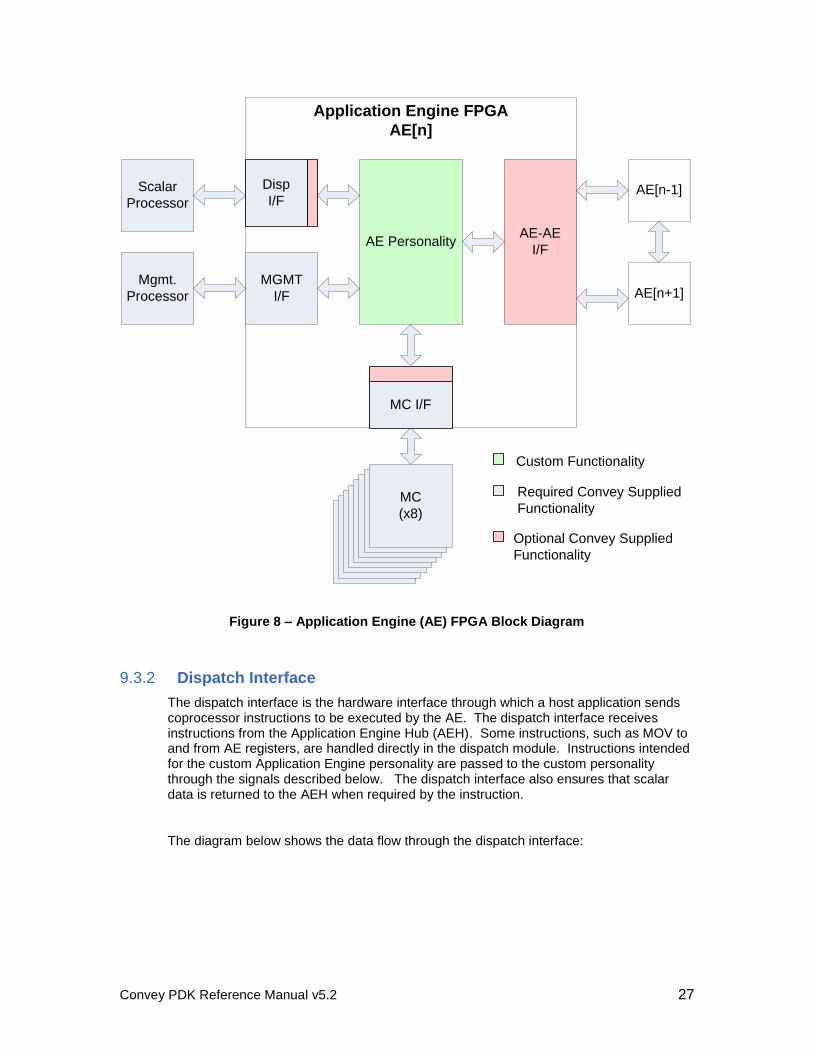
9.3.1 Application Engine (AE) FPGA block diagram
The diagram below shows the Application Engine FPGA with the interfaces to the rest of the coprocessor:
Dispatch Interface
Memory Controller Interface
AE-AE Interface
Management/Debug Interface
Convey PDK Reference Manual v5.2 27
Application Engine FPGA
AE[n]
Scalar
Processor
MCMCMCMCMCMCMCMC
(x8)
AE-AE
I/F
AE[n-1]
AE[n+1]MGMT
I/F
Mgmt.
Processor
AE Personality
MC I/F
Disp
I/F
Custom Functionality
Required Convey Supplied
Functionality
Optional Convey Supplied
Functionality
Figure 8 – Application Engine (AE) FPGA Block Diagram
9.3.2 Dispatch Interface
The dispatch interface is the hardware interface through which a host application sends coprocessor instructions to be executed by the AE. The dispatch interface receives instructions from the Application Engine Hub (AEH). Some instructions, such as MOV to and from AE registers, are handled directly in the dispatch module. Instructions intended for the custom Application Engine personality are passed to the custom personality through the signals described below. The dispatch interface also ensures that scalar data is returned to the AEH when required by the instruction.
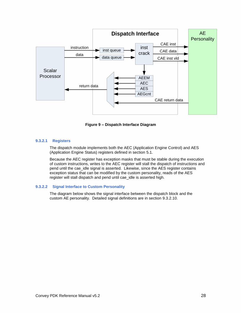
The diagram below shows the data flow through the dispatch interface:
Convey PDK Reference Manual v5.2 28
Dispatch Interface AE
Personality
inst queue
AEC
AES
data queuedata
Scalar
Processor
return data
inst
crack
instructionCAE data
CAE inst
CAE return data
AEEM
AEGcnt
CAE inst vld
Figure 9 – Dispatch Interface Diagram
9.3.2.1 Registers
The dispatch module implements both the AEC (Application Engine Control) and AES (Application Engine Status) registers defined in section 5.1.
Because the AEC register has exception masks that must be stable during the execution of custom instructions, writes to the AEC register will stall the dispatch of instructions and pend until the cae_idle signal is asserted. Likewise, since the AES register contains exception status that can be modified by the custom personality, reads of the AES register will stall dispatch and pend until cae_idle is asserted high.
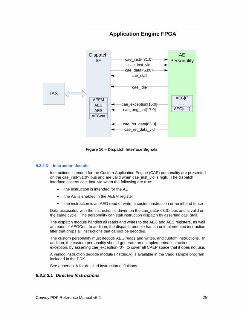
9.3.2.2 Signal Interface to Custom Personality
The diagram below shows the signal interface between the dispatch block and the custom AE personality. Detailed signal definitions are in section 9.3.2.10.
Convey PDK Reference Manual v5.2 29
Application Engine FPGA
IAS
Dispatch
I/F
AE
Personalitycae_instr<31:0>
cae_inst_vld
cae_idle
cae_data<63:0>
cae_stall
cae_exception[15:0]
cae_aeg_cnt[17:0]
cae_ret_data[63:0]
cae_ret_data_vld
AEC
AES
AEGcnt
AEG[0]
...
AEG[n-1]
AEEM
Figure 10 – Dispatch Interface Signals
9.3.2.3 Instruction decode
Instructions intended for the Custom Application Engine (CAE) personality are presented on the cae_inst<31:0> bus and are valid when cae_inst_vld is high. The dispatch interface asserts cae_inst_vld when the following are true:
the instruction is intended for the AE
the AE is enabled in the AEEM register
the instruction is an AEG read or write, a custom instruction or an inband fence
Data associated with the instruction is driven on the cae_data<63:0> bus and is valid on the same cycle. The personality can stall instruction dispatch by asserting cae_stall.
The dispatch module handles all reads and writes to the AEC and AES registers, as well as reads of AEGCnt. In addition, the dispatch module has an unimplemented instruction filter that drops all instructions that cannot be decoded.
The custom personality must decode AEG reads and writes, and custom instructions. In addition, the custom personality should generate an unimplemented instruction exception, by asserting cae_exception<0>, to cover all CAEP space that it does not use.
A verilog instruction decode module (instdec.v) is available in the Vadd sample program included in the PDK.
See appendix A for detailed instruction definitions.
9.3.2.3.1 Directed Instructions
Convey PDK Reference Manual v5.2 30
Directed instructions are indicated with an AEx suffix (CAEP*.AEx and MOV.AEx) are sent to the custom personality only if (x==ae_index) and the AE is enabled in the AEEM register.
9.3.2.3.2 Masked Instructions
Masked instructions (CAEP* and MOV to and from AEG registers) are sent to the personality if the AE is enabled in the AEEM register.
9.3.2.4 Scalar return data
Scalar data is returned to the AEH on the cae_ret_data<63:0> bus. The custom AE should drive cae_ret_data_vld high when the data is valid.
All coprocessor instructions that require returned scalar data must return data, even if they are unimplemented in the Application Engine. In addition, ordering of scalar return data must be preserved. The Convey-supplied dispatch module in the CAE FPGA ensures that AEC/AES/AEGcnt/AEG data is returned in the correct order. However, the CAE personality must guarantee that reads of AEG registers stay ordered appropriately.
9.3.2.5 AEG_CNT
The CAE sets the AEG_CNT field in the dispatch module by driving the count value on cae_aeg_cnt<17:0>, which remains static for a given personality.
9.3.2.6 Fence Mode
A fence instruction is sent by the AEH to guarantee ordering of memory loads and stores. All instructions issued before the fence will execute before instructions issued after the fence (See the Convey Reference Manual for details about when fences should be used). Custom personalities utilize the sideband fence for handling fence instructions. The dispatch module handles the fence instruction and hides the complexity from the CAE. When the dispatch module receives a fence instruction, it stalls inbound instructions until cae_idle is driven high by the CAE before sending a fence command directly to the MC interfaces.
9.3.2.7 Dispatch stall
The custom personality can stall the dispatch of new instructions by asserting the cae_stall signal. The cae_stall signal is registered in the dispatch block, so instruction dispatch is stalled one clock cycle after cae_stall is asserted.
9.3.2.8 CAE Idle Status
The CAE must indicate idle status via the cae_idle signal so that the dispatch module can correctly handle fence instructions and some register accesses as described in section 9.3.2.1. This signal must indicate true idle status—all pending memory operations in the CAE must be processed before cae_idle goes high.
9.3.2.9 Exceptions
Exceptions are sent by the custom personality on the cae_exception<15:0> bus. Bit 0 is defined to be the unimplemented instruction exception (see section 5.1). This exception can be set by the personality as well as by the dispatch module. When any of the cae_exception signals are asserted, the exception is logged in the AES register in the dispatch interface. If the exception is not masked in the AEC register, a trap is sent back to the host processor. The program can clear the exception by writing the AES register.
Convey PDK Reference Manual v5.2 31
The AES register is automatically cleared when a new program is dispatched to the coprocessor.
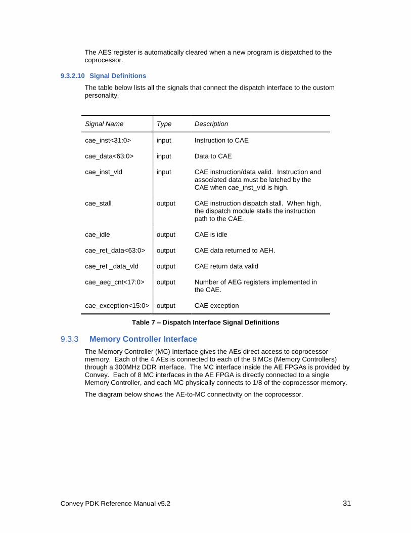
9.3.2.10 Signal Definitions
The table below lists all the signals that connect the dispatch interface to the custom personality.
Signal Name Type Description
cae_inst<31:0> input Instruction to CAE
cae_data<63:0> input Data to CAE
cae_inst_vld input CAE instruction/data valid. Instruction and associated data must be latched by the CAE when cae_inst_vld is high.
cae_stall output CAE instruction dispatch stall. When high, the dispatch module stalls the instruction path to the CAE.
cae_idle output CAE is idle
cae_ret_data<63:0> output CAE data returned to AEH.
cae_ret _data_vld output CAE return data valid
cae_aeg_cnt<17:0> output Number of AEG registers implemented in the CAE.
cae_exception<15:0> output CAE exception
Table 7 – Dispatch Interface Signal Definitions
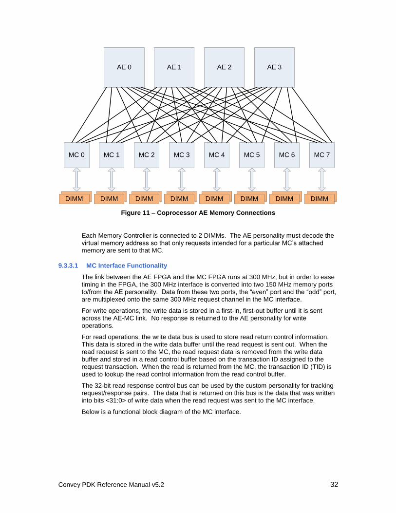
9.3.3 Memory Controller Interface
The Memory Controller (MC) Interface gives the AEs direct access to coprocessor memory. Each of the 4 AEs is connected to each of the 8 MCs (Memory Controllers) through a 300MHz DDR interface. The MC interface inside the AE FPGAs is provided by Convey. Each of 8 MC interfaces in the AE FPGA is directly connected to a single Memory Controller, and each MC physically connects to 1/8 of the coprocessor memory.
The diagram below shows the AE-to-MC connectivity on the coprocessor.
Convey PDK Reference Manual v5.2 32
MC 0
DIMM DIMM DIMM DIMM
AE 0
DIMM DIMM DIMM DIMM
AE 1 AE 2 AE 3
MC 1 MC 2 MC 3 MC 4 MC 5 MC 6 MC 7
Figure 11 – Coprocessor AE Memory Connections
Each Memory Controller is connected to 2 DIMMs. The AE personality must decode the virtual memory address so that only requests intended for a particular MC’s attached memory are sent to that MC.
9.3.3.1 MC Interface Functionality
The link between the AE FPGA and the MC FPGA runs at 300 MHz, but in order to ease timing in the FPGA, the 300 MHz interface is converted into two 150 MHz memory ports to/from the AE personality. Data from these two ports, the “even” port and the “odd” port, are multiplexed onto the same 300 MHz request channel in the MC interface.
For write operations, the write data is stored in a first-in, first-out buffer until it is sent across the AE-MC link. No response is returned to the AE personality for write operations.
For read operations, the write data bus is used to store read return control information. This data is stored in the write data buffer until the read request is sent out. When the read request is sent to the MC, the read request data is removed from the write data buffer and stored in a read control buffer based on the transaction ID assigned to the request transaction. When the read is returned from the MC, the transaction ID (TID) is used to lookup the read control information from the read control buffer.
The 32-bit read response control bus can be used by the custom personality for tracking request/response pairs. The data that is returned on this bus is the data that was written into bits <31:0> of write data when the read request was sent to the MC interface.
Below is a functional block diagram of the MC interface.
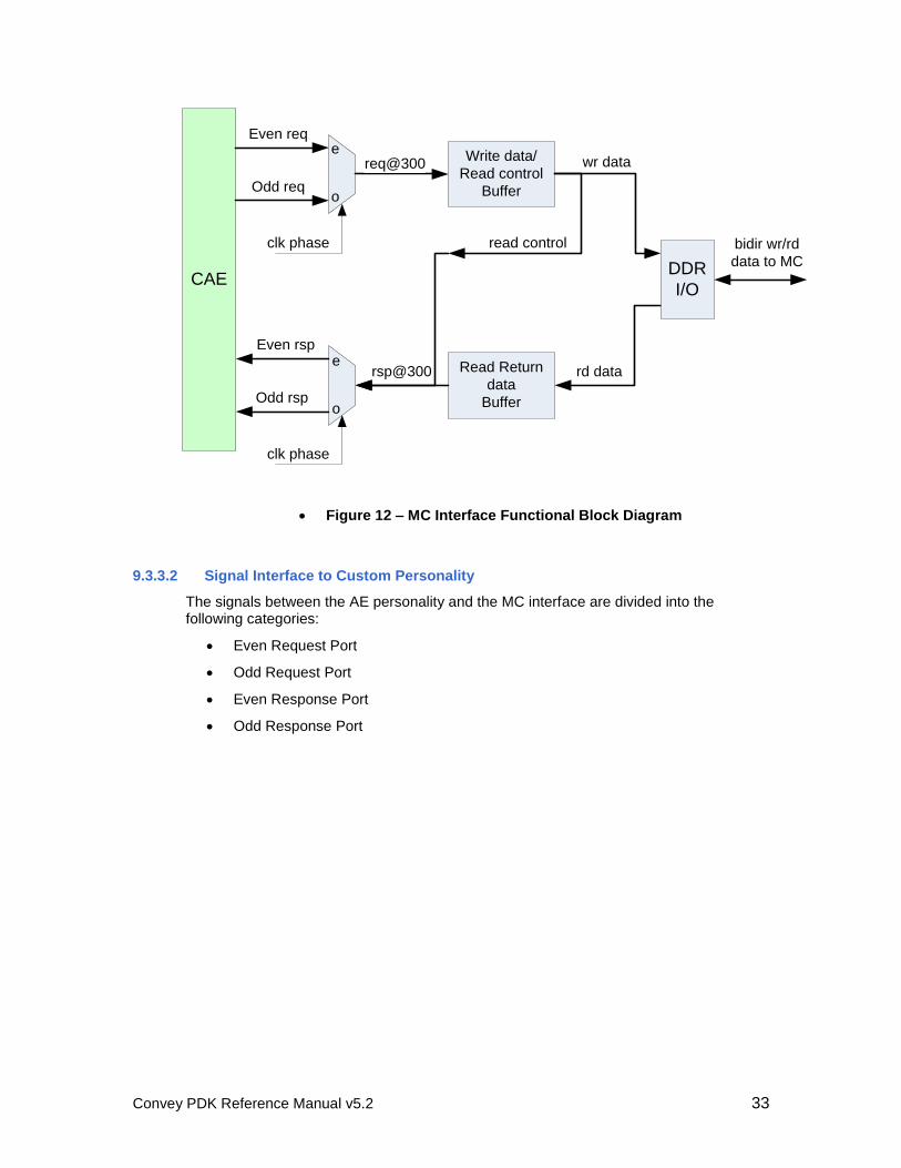
Convey PDK Reference Manual v5.2 33
CAE
Even req
clk phase
Write data/
Read control
BufferOdd req
req@300 wr data
read control
Read Return
data
Buffer
rd datarsp@300
Even rsp
Odd rsp
clk phase
DDR
I/O
e
o
e
o
bidir wr/rd
data to MC
Figure 12 – MC Interface Functional Block Diagram
9.3.3.2 Signal Interface to Custom Personality
The signals between the AE personality and the MC interface are divided into the following categories:
Even Request Port
Odd Request Port
Even Response Port
Odd Response Port
Convey PDK Reference Manual v5.2 34
CAEMC
DIMM
MC I/F (x8)
mc_rd_rq_stall_o
mc_req_ld_e
mc_req_st_e
mc_req_size_e<1:0>
mc_req_vadr_e<47:0>
mc_req_wrd_rdctl_e<63:0>
mc_rd_rq_stall_e
Even
request
port
Odd
request
port
mc_rsp_push_e
mc_rsp_stall_e
mc_rsp_data_e<63:0>
mc_rsp_rdctl_e<31:0>
mc_rsp_data_o<63:0>
mc_rsp_rdctl_o<31:0>
Even
Resp
port
mc_req_ld_o
mc_req_st_o
mc_req_size_o<1:0>
mc_req_vadr_o<47:0>
mc_req_wrd_rdctl_o<63:0>
mc_rsp_push_o
mc_rsp_stall_o Odd
Resp
port
Application Engine FPGA
mc_req_flush_e
mc_rsp_flush_cmplt_e
mc_req_flush_o
mc_rsp_flush_cmplt_o
mc_wr_rq_stall_o
mc_wr_rq_stall_e
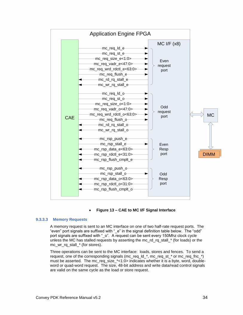
Figure 13 – CAE to MC I/F Signal Interface
9.3.3.3 Memory Requests
A memory request is sent to an MC interface on one of two half-rate request ports. The “even” port signals are suffixed with “_e” in the signal definition table below. The “odd” port signals are suffixed with “_o”. A request can be sent every 150Mhz clock cycle unless the MC has stalled requests by asserting the mc_rd_rq_stall_* (for loads) or the mc_wr_rq_stall_* (for stores).
Three operations can be sent to the MC interface: loads, stores and fences. To send a request, one of the corresponding signals (mc_req_ld_*, mc_req_st_* or mc_req_fnc_*) must be asserted. The mc_req_size_*<1:0> indicates whether it is a byte, word, double-word or quad-word request. The size, 48-bit address and write data/read control signals are valid on the same cycle as the load or store request.
Convey PDK Reference Manual v5.2 35
9.3.3.3.1 Stores
Stores to memory are done by driving the appropriate 64-bit data value on the mc_req_wrd_rdctl_*<63:0> bus. Four request sizes are supported, byte, word, double-word and quad word, determined by the mc_req_size_*<1:0> field. For store sizes less than quad word, the data must be correctly aligned on the data bus and all other bits are don’t-cares. For instance, on a double-word write to offset 0x4, the data must be driven on bits [63:32] of the data bus.
In order to prevent errors in data placement, and to allow the data to be correctly placed regardless of address offset, the data can be replicated across the bus. For instance to write the two-byte value 0xCAFE, driving the data 0xCAFECAFE will ensure the correct data is stored. Note, however, that the address must always be aligned correctly for the size of the transaction.
9.3.3.3.2 Loads
Loads from memory use the 64-bit write data/read control bus (mc_req_wrd_rdctl_*<63:0>) to send read control information to the MC. The lower 32 bits of this data is stored by the MC and returned as mc_rsp_rdctl_*<31:0>. This field should be used by the custom personality to uniquely identify request/response pairs. Some of these bits are utilized by optional MC interface functions described in Section 9.3.7.
For load requests, the four request sizes are supported, byte, word, double-word and quad word, determined by the mc_req_size_*<1:0> field.
9.3.3.3.3 Fences
Fence instructions are sent by the AEH to enforce ordering of loads and stores to memory. PDK designs utilize the sideband fence, so the dispatch unit and memory controller handle the fence appropriately and effectively hide the fence instruction from the custom personality.
9.3.3.3.4 Request Stalls
Two stall signals, mc_rd_rq_stall_* and mc_wr_rq_stall_*, are sent from the MC interface to stall read requests and write requests, respectively. When a stall asserts, the personality must stop sending requests within two cycles to avoid overflowing buffers in the MC interface.
9.3.3.4 Memory Responses
Responses are returned (for load requests only), to one of two response ports. These ports are clocked at 150 MHz.
Response data is always returned aligned at byte 0, regardless of the address offset within the 64-bits. For instance, a single byte load from offset 0x2 will be returned in the least-significant byte, and the other 7 bytes of data are invalid.
Responses are pushed from the MC on every cycle that mc_rsp_push_* is asserted. Response pushes from the MC can be stalled by the custom personality using the mc_rsp_stall_* signals. The MC can send up to five additional responses after the stall is asserted, so this signal should be connected to a FIFO “almost full” signal to allow space for responses in-flight.
Convey PDK Reference Manual v5.2 36
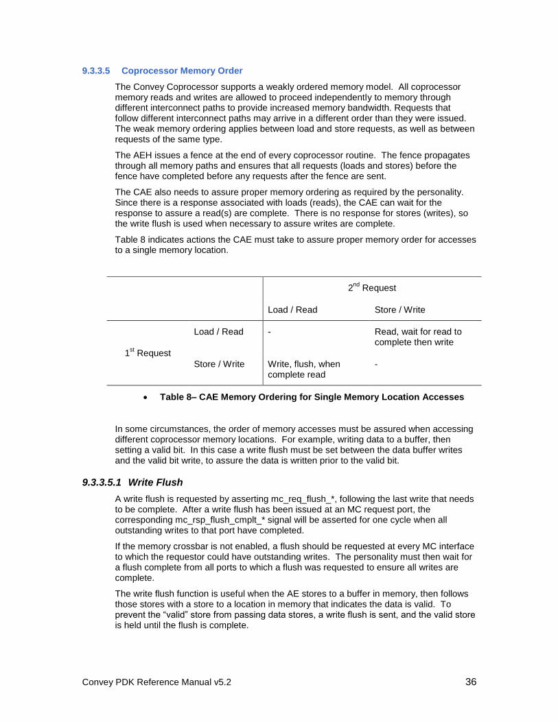
9.3.3.5 Coprocessor Memory Order
The Convey Coprocessor supports a weakly ordered memory model. All coprocessor memory reads and writes are allowed to proceed independently to memory through different interconnect paths to provide increased memory bandwidth. Requests that follow different interconnect paths may arrive in a different order than they were issued. The weak memory ordering applies between load and store requests, as well as between requests of the same type.
The AEH issues a fence at the end of every coprocessor routine. The fence propagates through all memory paths and ensures that all requests (loads and stores) before the fence have completed before any requests after the fence are sent.
The CAE also needs to assure proper memory ordering as required by the personality. Since there is a response associated with loads (reads), the CAE can wait for the response to assure a read(s) are complete. There is no response for stores (writes), so the write flush is used when necessary to assure writes are complete.
Table 8 indicates actions the CAE must take to assure proper memory order for accesses to a single memory location.
2nd
Request
Load / Read Store / Write
1st Request
Load / Read - Read, wait for read to complete then write
Store / Write Write, flush, when complete read
-
Table 8– CAE Memory Ordering for Single Memory Location Accesses
In some circumstances, the order of memory accesses must be assured when accessing different coprocessor memory locations. For example, writing data to a buffer, then setting a valid bit. In this case a write flush must be set between the data buffer writes and the valid bit write, to assure the data is written prior to the valid bit.
9.3.3.5.1 Write Flush
A write flush is requested by asserting mc_req_flush_*, following the last write that needs to be complete. After a write flush has been issued at an MC request port, the corresponding mc_rsp_flush_cmplt_* signal will be asserted for one cycle when all outstanding writes to that port have completed.
If the memory crossbar is not enabled, a flush should be requested at every MC interface to which the requestor could have outstanding writes. The personality must then wait for a flush complete from all ports to which a flush was requested to ensure all writes are complete.
The write flush function is useful when the AE stores to a buffer in memory, then follows those stores with a store to a location in memory that indicates the data is valid. To prevent the “valid” store from passing data stores, a write flush is sent, and the valid store is held until the flush is complete.
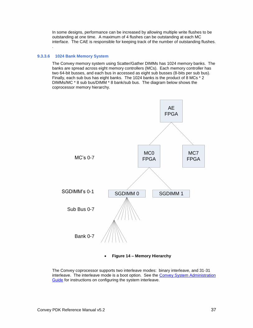
Convey PDK Reference Manual v5.2 37
In some designs, performance can be increased by allowing multiple write flushes to be outstanding at one time. A maximum of 4 flushes can be outstanding at each MC interface. The CAE is responsible for keeping track of the number of outstanding flushes. .
9.3.3.6 1024 Bank Memory System
The Convey memory system using Scatter/Gather DIMMs has 1024 memory banks. The banks are spread across eight memory controllers (MCs). Each memory controller has two 64-bit busses, and each bus in accessed as eight sub busses (8-bits per sub bus). Finally, each sub bus has eight banks. The 1024 banks is the product of 8 MCs * 2 DIMMs/MC * 8 sub bus/DIMM * 8 bank/sub bus. The diagram below shows the coprocessor memory hierarchy.
AE
FPGA
MC0
FPGA
SGDIMM 0 SGDIMM 1
MC’s 0-7
SGDIMM’s 0-1
Sub Bus 0-7
Bank 0-7
MC7
FPGA
Figure 14 – Memory Hierarchy
The Convey coprocessor supports two interleave modes: binary interleave, and 31-31 interleave. The interleave mode is a boot option. See the Convey System Administration Guide for instructions on configuring the system interleave.
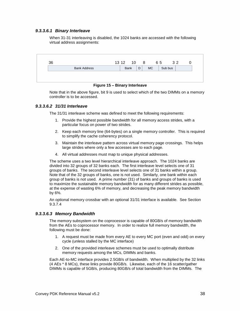
Convey PDK Reference Manual v5.2 38
9.3.3.6.1 Binary Interleave
When 31-31 interleaving is disabled, the 1024 banks are accessed with the following virtual address assignments:
02
Sub bus
35
MC
68
DBank
1012
Bank Address
1336
Figure 15 – Binary Interleave
Note that in the above figure, bit 9 is used to select which of the two DIMMs on a memory controller is to be accessed.
9.3.3.6.2 31/31 Interleave
The 31/31 interleave scheme was defined to meet the following requirements:
1. Provide the highest possible bandwidth for all memory access strides, with a particular focus on power of two strides.
2. Keep each memory line (64-bytes) on a single memory controller. This is required to simplify the cache coherency protocol.
3. Maintain the interleave pattern across virtual memory page crossings. This helps large strides where only a few accesses are to each page.
4. All virtual addresses must map to unique physical addresses.
The scheme uses a two level hierarchical interleave approach. The 1024 banks are divided into 32 groups of 32 banks each. The first interleave level selects one of 31 groups of banks. The second interleave level selects one of 31 banks within a group. Note that of the 32 groups of banks, one is not used. Similarly, one bank within each group of banks is not used. A prime number (31) of banks and groups of banks is used to maximize the sustainable memory bandwidth for as many different strides as possible, at the expense of wasting 6% of memory, and decreasing the peak memory bandwidth by 6%.
An optional memory crossbar with an optional 31/31 interface is available. See Section 9.3.7.4
9.3.3.6.3 Memory Bandwidth
The memory subsystem on the coprocessor is capable of 80GB/s of memory bandwidth from the AEs to coprocessor memory. In order to realize full memory bandwidth, the following must be done:
1. A request must be made from every AE to every MC port (even and odd) on every cycle (unless stalled by the MC interface)
2. One of the provided interleave schemes must be used to optimally distribute memory requests among the MCs, DIMMs and banks.
Each AE-to-MC interface provides 2.5GB/s of bandwidth. When multiplied by the 32 links (4 AEs * 8 MCs), these links provide 80GB/s. Likewise, each of the 16 scatter/gather DIMMs is capable of 5GB/s, producing 80GB/s of total bandwidth from the DIMMs. The
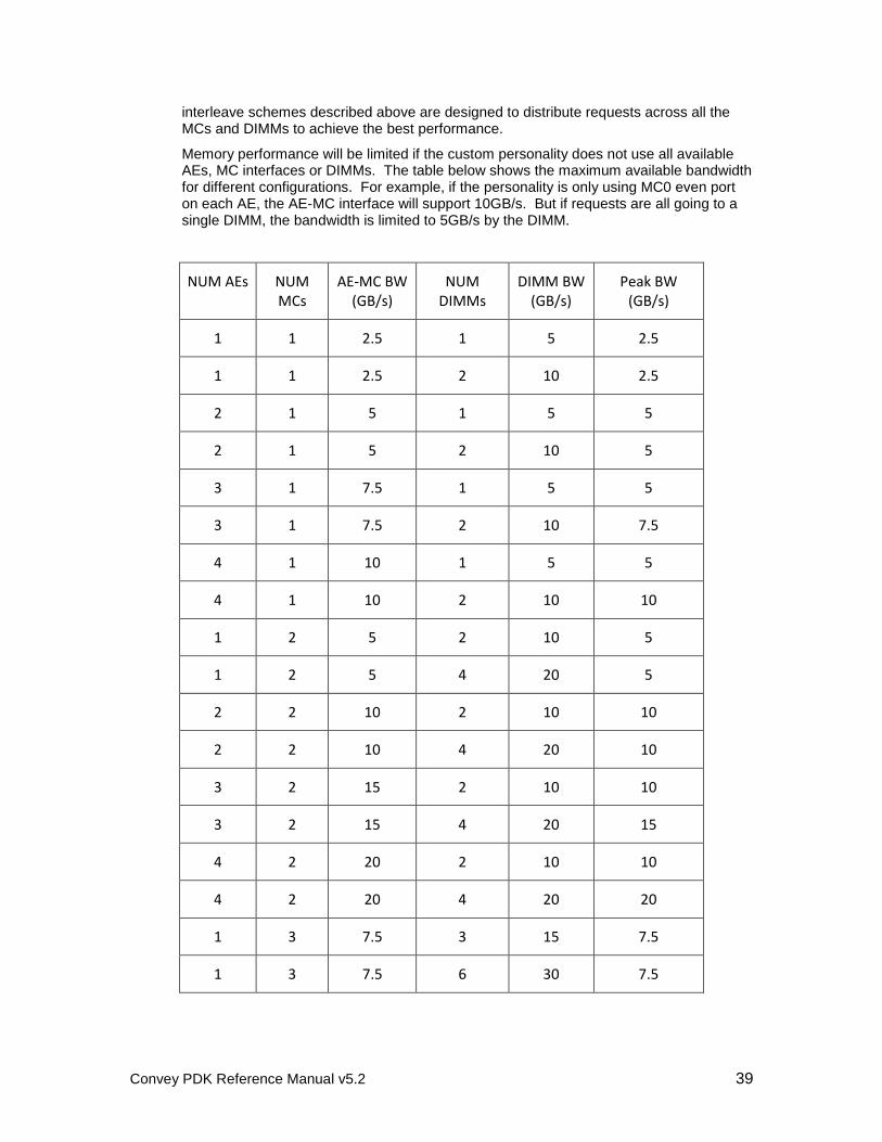
Convey PDK Reference Manual v5.2 39
interleave schemes described above are designed to distribute requests across all the MCs and DIMMs to achieve the best performance.
Memory performance will be limited if the custom personality does not use all available AEs, MC interfaces or DIMMs. The table below shows the maximum available bandwidth for different configurations. For example, if the personality is only using MC0 even port on each AE, the AE-MC interface will support 10GB/s. But if requests are all going to a single DIMM, the bandwidth is limited to 5GB/s by the DIMM.
NUM AEs NUM MCs
AE-MC BW (GB/s)
NUM DIMMs
DIMM BW (GB/s)
Peak BW (GB/s)
1 1 2.5 1 5 2.5
1 1 2.5 2 10 2.5
2 1 5 1 5 5
2 1 5 2 10 5
3 1 7.5 1 5 5
3 1 7.5 2 10 7.5
4 1 10 1 5 5
4 1 10 2 10 10
1 2 5 2 10 5
1 2 5 4 20 5
2 2 10 2 10 10
2 2 10 4 20 10
3 2 15 2 10 10
3 2 15 4 20 15
4 2 20 2 10 10
4 2 20 4 20 20
1 3 7.5 3 15 7.5
1 3 7.5 6 30 7.5
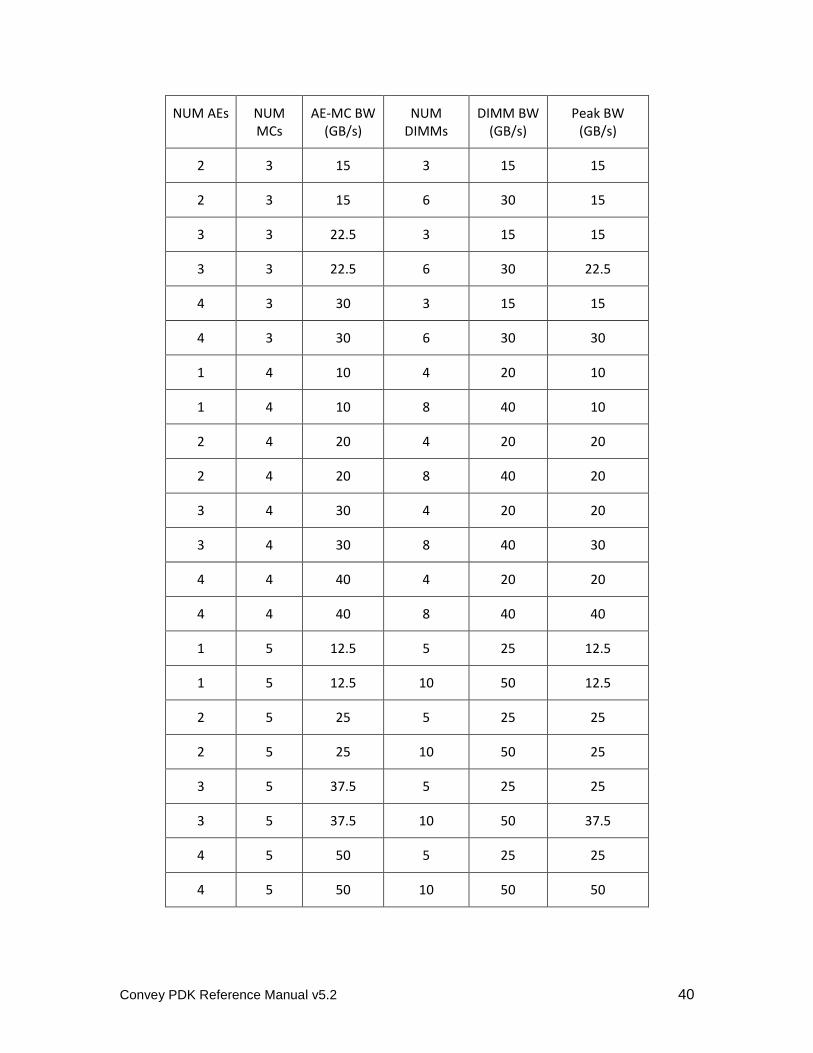
Convey PDK Reference Manual v5.2 40
NUM AEs NUM MCs
AE-MC BW (GB/s)
NUM DIMMs
DIMM BW (GB/s)
Peak BW (GB/s)
2 3 15 3 15 15
2 3 15 6 30 15
3 3 22.5 3 15 15
3 3 22.5 6 30 22.5
4 3 30 3 15 15
4 3 30 6 30 30
1 4 10 4 20 10
1 4 10 8 40 10
2 4 20 4 20 20
2 4 20 8 40 20
3 4 30 4 20 20
3 4 30 8 40 30
4 4 40 4 20 20
4 4 40 8 40 40
1 5 12.5 5 25 12.5
1 5 12.5 10 50 12.5
2 5 25 5 25 25
2 5 25 10 50 25
3 5 37.5 5 25 25
3 5 37.5 10 50 37.5
4 5 50 5 25 25
4 5 50 10 50 50
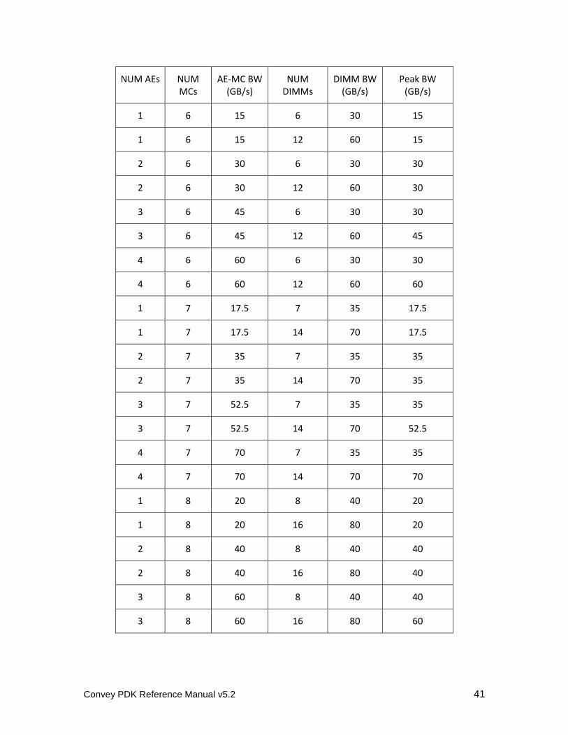
Convey PDK Reference Manual v5.2 41
NUM AEs NUM MCs
AE-MC BW (GB/s)
NUM DIMMs
DIMM BW (GB/s)
Peak BW (GB/s)
1 6 15 6 30 15
1 6 15 12 60 15
2 6 30 6 30 30
2 6 30 12 60 30
3 6 45 6 30 30
3 6 45 12 60 45
4 6 60 6 30 30
4 6 60 12 60 60
1 7 17.5 7 35 17.5
1 7 17.5 14 70 17.5
2 7 35 7 35 35
2 7 35 14 70 35
3 7 52.5 7 35 35
3 7 52.5 14 70 52.5
4 7 70 7 35 35
4 7 70 14 70 70
1 8 20 8 40 20
1 8 20 16 80 20
2 8 40 8 40 40
2 8 40 16 80 40
3 8 60 8 40 40
3 8 60 16 80 60
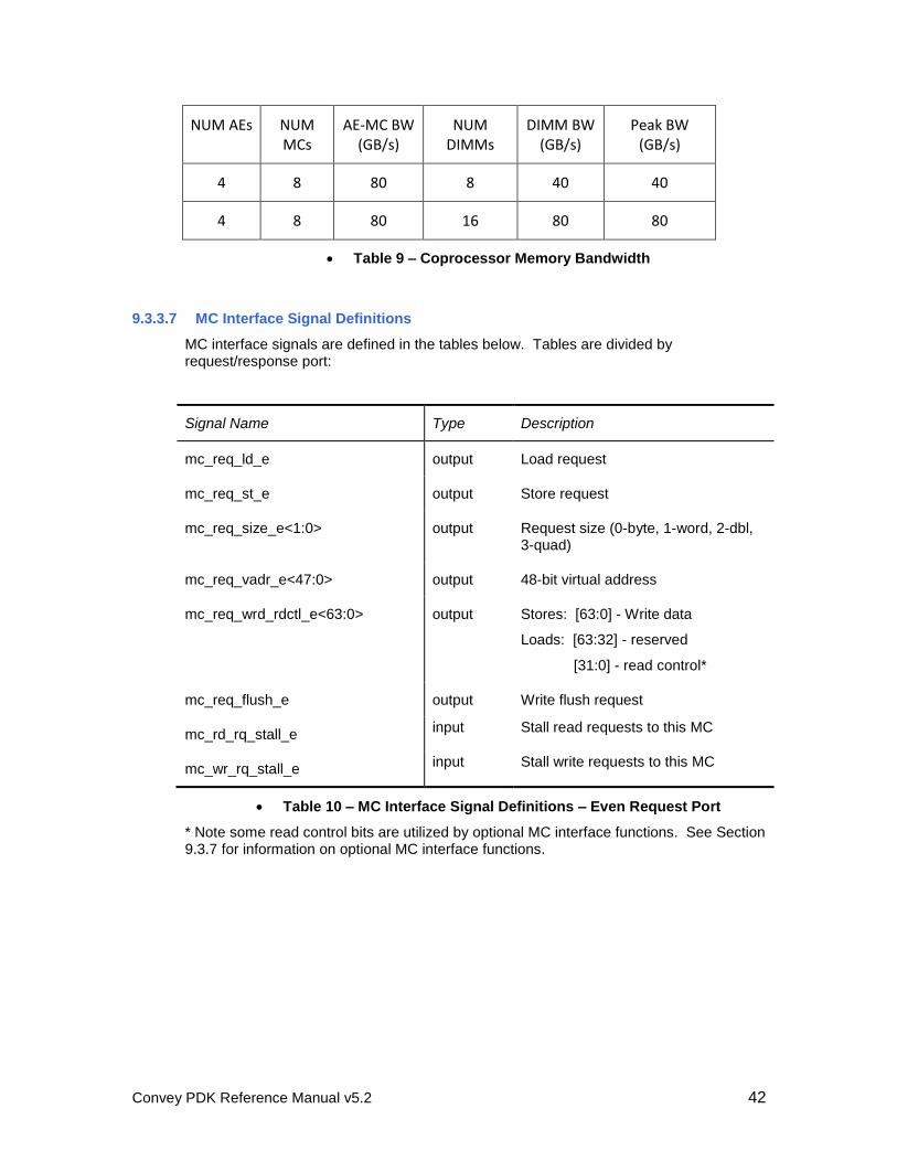
Convey PDK Reference Manual v5.2 42
NUM AEs NUM MCs
AE-MC BW (GB/s)
NUM DIMMs
DIMM BW (GB/s)
Peak BW (GB/s)
4 8 80 8 40 40
4 8 80 16 80 80
Table 9 – Coprocessor Memory Bandwidth
9.3.3.7 MC Interface Signal Definitions
MC interface signals are defined in the tables below. Tables are divided by request/response port:
Signal Name Type Description
mc_req_ld_e output Load request
mc_req_st_e output Store request
mc_req_size_e<1:0> output Request size (0-byte, 1-word, 2-dbl, 3-quad)
mc_req_vadr_e<47:0> output 48-bit virtual address
mc_req_wrd_rdctl_e<63:0> output Stores: [63:0] - Write data
Loads: [63:32] - reserved
[31:0] - read control*
mc_req_flush_e output Write flush request
mc_rd_rq_stall_e input Stall read requests to this MC
mc_wr_rq_stall_e input Stall write requests to this MC
Table 10 – MC Interface Signal Definitions – Even Request Port
* Note some read control bits are utilized by optional MC interface functions. See Section 9.3.7 for information on optional MC interface functions.
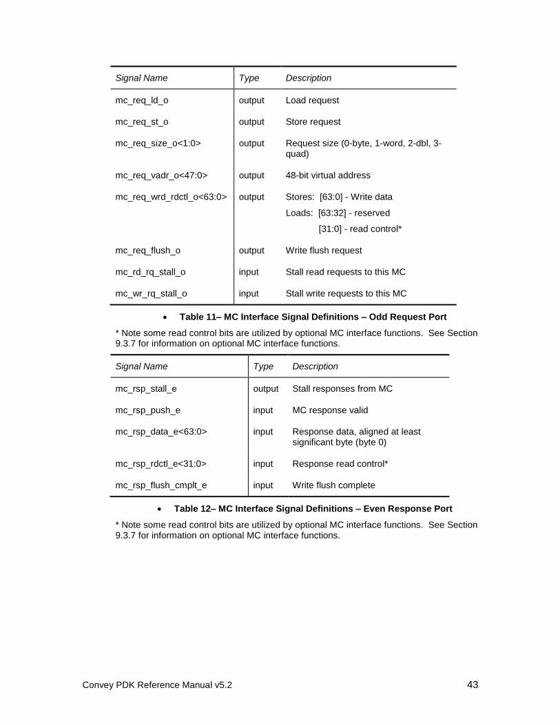
Convey PDK Reference Manual v5.2 43
Signal Name Type Description
mc_req_ld_o output Load request
mc_req_st_o output Store request
mc_req_size_o<1:0> output Request size (0-byte, 1-word, 2-dbl, 3-quad)
mc_req_vadr_o<47:0> output 48-bit virtual address
mc_req_wrd_rdctl_o<63:0> output Stores: [63:0] - Write data
Loads: [63:32] - reserved
[31:0] - read control*
mc_req_flush_o output Write flush request
mc_rd_rq_stall_o input Stall read requests to this MC
mc_wr_rq_stall_o input Stall write requests to this MC
Table 11– MC Interface Signal Definitions – Odd Request Port
* Note some read control bits are utilized by optional MC interface functions. See Section 9.3.7 for information on optional MC interface functions.
Signal Name Type Description
mc_rsp_stall_e output Stall responses from MC
mc_rsp_push_e input MC response valid
mc_rsp_data_e<63:0> input Response data, aligned at least significant byte (byte 0)
mc_rsp_rdctl_e<31:0> input Response read control*
mc_rsp_flush_cmplt_e input Write flush complete
Table 12– MC Interface Signal Definitions – Even Response Port
* Note some read control bits are utilized by optional MC interface functions. See Section 9.3.7 for information on optional MC interface functions.
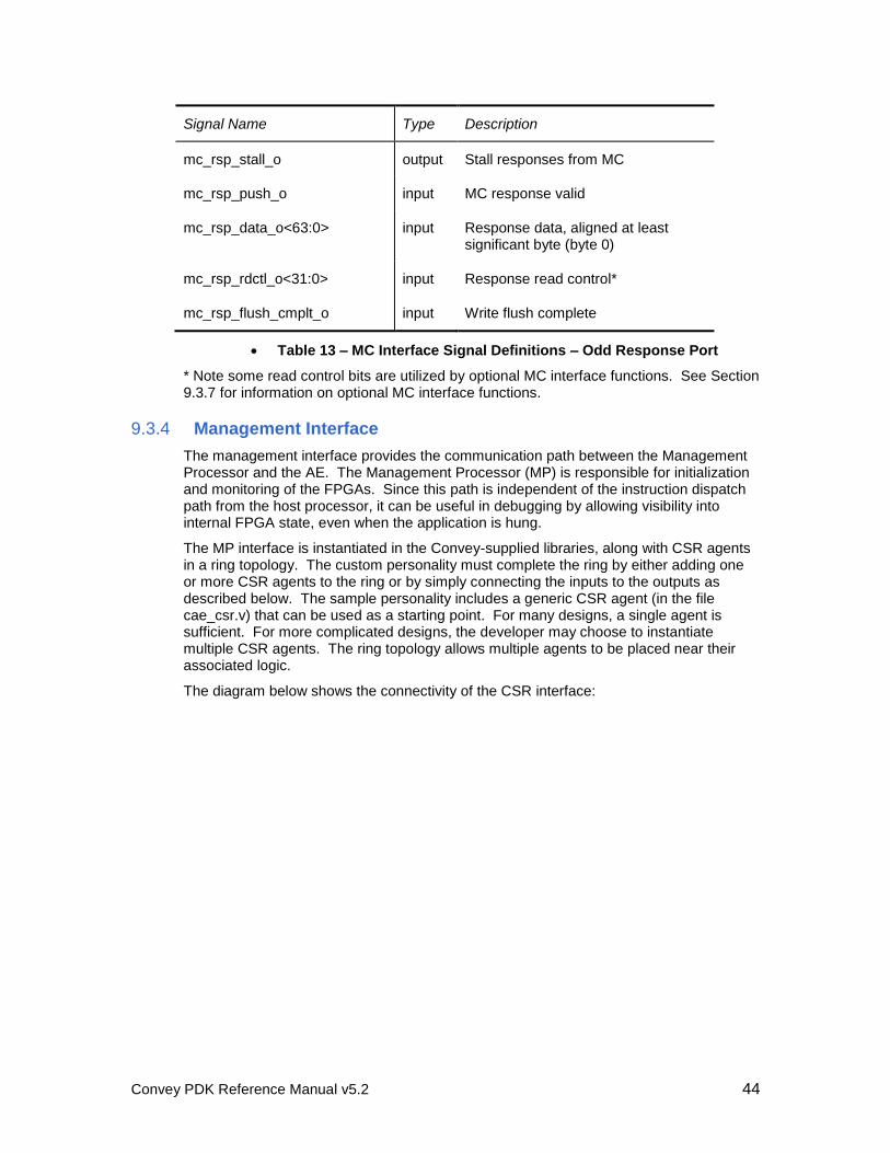
Convey PDK Reference Manual v5.2 44
Signal Name Type Description
mc_rsp_stall_o output Stall responses from MC
mc_rsp_push_o input MC response valid
mc_rsp_data_o<63:0> input Response data, aligned at least significant byte (byte 0)
mc_rsp_rdctl_o<31:0> input Response read control*
mc_rsp_flush_cmplt_o input Write flush complete
Table 13 – MC Interface Signal Definitions – Odd Response Port
* Note some read control bits are utilized by optional MC interface functions. See Section 9.3.7 for information on optional MC interface functions.
9.3.4 Management Interface
The management interface provides the communication path between the Management Processor and the AE. The Management Processor (MP) is responsible for initialization and monitoring of the FPGAs. Since this path is independent of the instruction dispatch path from the host processor, it can be useful in debugging by allowing visibility into internal FPGA state, even when the application is hung.
The MP interface is instantiated in the Convey-supplied libraries, along with CSR agents in a ring topology. The custom personality must complete the ring by either adding one or more CSR agents to the ring or by simply connecting the inputs to the outputs as described below. The sample personality includes a generic CSR agent (in the file cae_csr.v) that can be used as a starting point. For many designs, a single agent is sufficient. For more complicated designs, the developer may choose to instantiate multiple CSR agents. The ring topology allows multiple agents to be placed near their associated logic.
The diagram below shows the connectivity of the CSR interface:
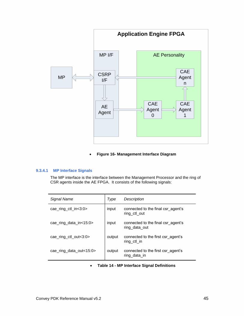
Convey PDK Reference Manual v5.2 45
Application Engine FPGA
MP I/F
MP
AE Personality
CSRP
I/F
AE
Agent
CAE
Agent
0
CAE
Agent
1
CAE
Agent
n
Figure 16- Management Interface Diagram
9.3.4.1 MP Interface Signals
The MP interface is the interface between the Management Processor and the ring of CSR agents inside the AE FPGA. It consists of the following signals:
Signal Name Type Description
cae_ring_ctl_in<3:0> input connected to the final csr_agent’s ring_ctl_out
cae_ring_data_in<15:0> input connected to the final csr_agent’s ring_data_out
cae_ring_ctl_out<3:0> output connected to the first csr_agent’s ring_ctl_in
cae_ring_data_out<15:0> output connected to the first csr_agent’s ring_data_in
Table 14 - MP Interface Signal Definitions
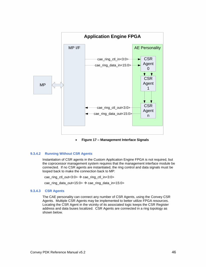
Convey PDK Reference Manual v5.2 46
Application Engine FPGA
MP
MP I/F AE Personality
cae_ring_ctl_in<3:0>
cae_ring_data_in<15:0>
cae_ring_ctl_out<3:0>
cae_ring_data_out<15:0>
CSR
Agent
0
CSR
Agent
1
CSR
Agent
n
Figure 17 – Management Interface Signals
9.3.4.2 Running Without CSR Agents
Instantiation of CSR agents in the Custom Application Engine FPGA is not required, but the coprocessor management system requires that the management interface module be connected. If no CSR agents are instantiated, the ring control and data signals must be looped back to make the connection back to MP:
cae_ring_ctl_out<3:0> cae_ring_ctl_in<3:0>
cae_ring_data_out<15:0> cae_ring_data_in<15:0>
9.3.4.3 CSR Agents
The CAE personality can connect any number of CSR Agents, using the Convey CSR Agents. Multiple CSR Agents may be implemented to better utilize FPGA resources. Locating the CSR Agent in the vicinity of its associated logic keeps the CSR Register address and data buses localized. CSR Agents are connected in a ring topology as shown below.
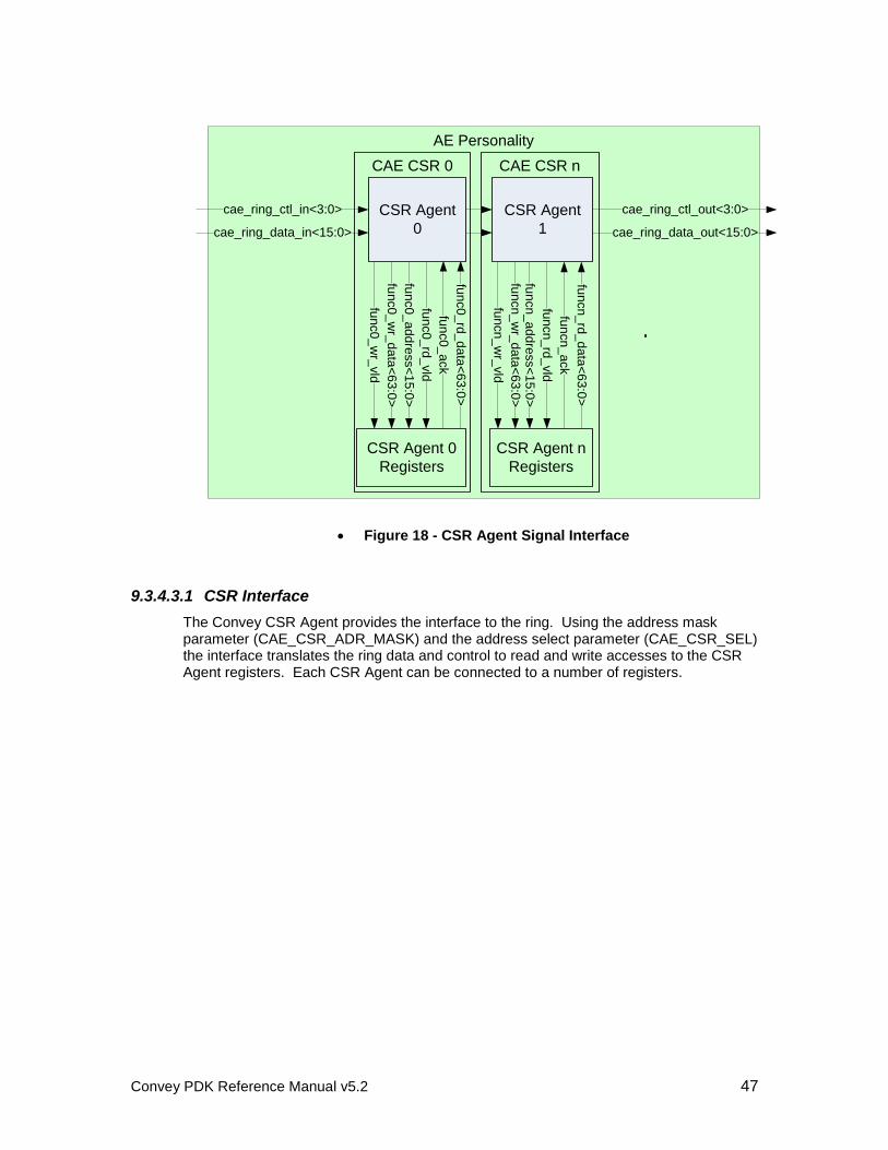
Convey PDK Reference Manual v5.2 47
AE Personality
cae_ring_ctl_in<3:0>
cae_ring_data_in<15:0>
fun
c0
_a
dd
ress<
15
:0>
cae_ring_ctl_out<3:0>
cae_ring_data_out<15:0>
fun
c0
_w
r_d
ata
<6
3:0
>
fun
c0
_w
r_vld
fun
c0
_rd
_vld
fun
c0
_rd
_d
ata
<6
3:0
>
fun
cn_
wr_
vld
fun
cn_
wr_
da
ta<
63
:0>
fun
cn_
ad
dre
ss<
15
:0>
fun
cn_
rd_
vld
fun
cn_
rd_
da
ta<
63
:0>
CSR Agent 0
Registers
CSR Agent n
Registers
CSR Agent
1
CSR Agent
0
fun
c0
_a
ck
fun
cn
_a
ck
CAE CSR 0 CAE CSR n
Figure 18 - CSR Agent Signal Interface
9.3.4.3.1 CSR Interface
The Convey CSR Agent provides the interface to the ring. Using the address mask parameter (CAE_CSR_ADR_MASK) and the address select parameter (CAE_CSR_SEL) the interface translates the ring data and control to read and write accesses to the CSR Agent registers. Each CSR Agent can be connected to a number of registers.
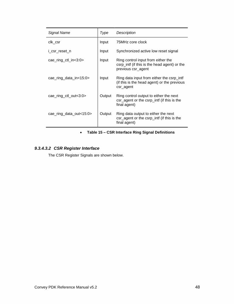
Convey PDK Reference Manual v5.2 48
Signal Name Type Description
clk_csr Input 75MHz core clock
i_csr_reset_n Input Synchronized active low reset signal
cae_ring_ctl_in<3:0> Input Ring control input from either the csrp_intf (if this is the head agent) or the previous csr_agent
cae_ring_data_in<15:0> Input Ring data input from either the csrp_intf (if this is the head agent) or the previous csr_agent
cae_ring_ctl_out<3:0> Output Ring control output to either the next csr_agent or the csrp_intf (if this is the final agent)
cae_ring_data_out<15:0> Output Ring data output to either the next csr_agent or the csrp_intf (if this is the final agent)
Table 15 – CSR Interface Ring Signal Definitions
9.3.4.3.2 CSR Register Interface
The CSR Register Signals are shown below.
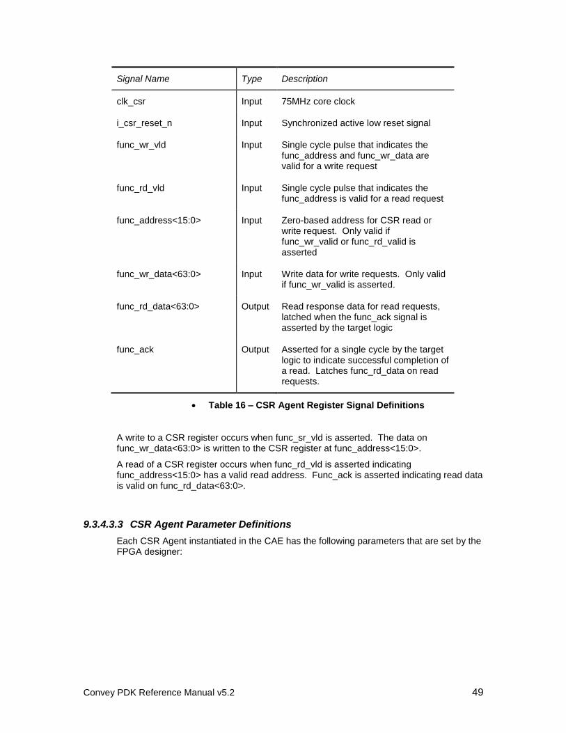
Convey PDK Reference Manual v5.2 49
Signal Name Type Description
clk_csr Input 75MHz core clock
i_csr_reset_n Input Synchronized active low reset signal
func_wr_vld Input Single cycle pulse that indicates the func_address and func_wr_data are valid for a write request
func_rd_vld Input Single cycle pulse that indicates the func_address is valid for a read request
func_address<15:0> Input Zero-based address for CSR read or write request. Only valid if func_wr_valid or func_rd_valid is asserted
func_wr_data<63:0> Input Write data for write requests. Only valid if func_wr_valid is asserted.
func_rd_data<63:0> Output Read response data for read requests, latched when the func_ack signal is asserted by the target logic
func_ack Output Asserted for a single cycle by the target logic to indicate successful completion of a read. Latches func_rd_data on read requests.
Table 16 – CSR Agent Register Signal Definitions
A write to a CSR register occurs when func_sr_vld is asserted. The data on func_wr_data<63:0> is written to the CSR register at func_address<15:0>.
A read of a CSR register occurs when func_rd_vld is asserted indicating func_address<15:0> has a valid read address. Func_ack is asserted indicating read data is valid on func_rd_data<63:0>.
9.3.4.3.3 CSR Agent Parameter Definitions
Each CSR Agent instantiated in the CAE has the following parameters that are set by the FPGA designer:
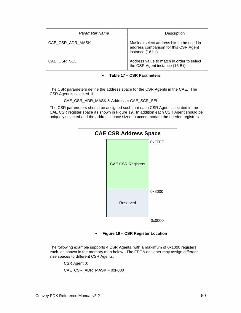
Convey PDK Reference Manual v5.2 50
Parameter Name Description
CAE_CSR_ADR_MASK Mask to select address bits to be used in address comparison for this CSR Agent instance (16 bit)
CAE_CSR_SEL Address value to match in order to select the CSR Agent instance (16 Bit)
Table 17 – CSR Parameters
The CSR parameters define the address space for the CSR Agents in the CAE. The CSR Agent is selected if
CAE_CSR_ADR_MASK & Address = CAE_SCR_SEL
The CSR parameters should be assigned such that each CSR Agent is located in the CAE CSR register space as shown in Figure 19. In addition each CSR Agent should be uniquely selected and the address space sized to accommodate the needed registers.
CAE CSR Address Space
CAE CSR Registers
Reserved
0xFFFF
0x8000
0x0000
Figure 19 – CSR Register Location
The following example supports 4 CSR Agents, with a maximum of 0x1000 registers each, as shown in the memory map below. The FPGA designer may assign different size spaces to different CSR Agents.
CSR Agent 0:
CAE_CSR_ADR_MASK = 0xF000
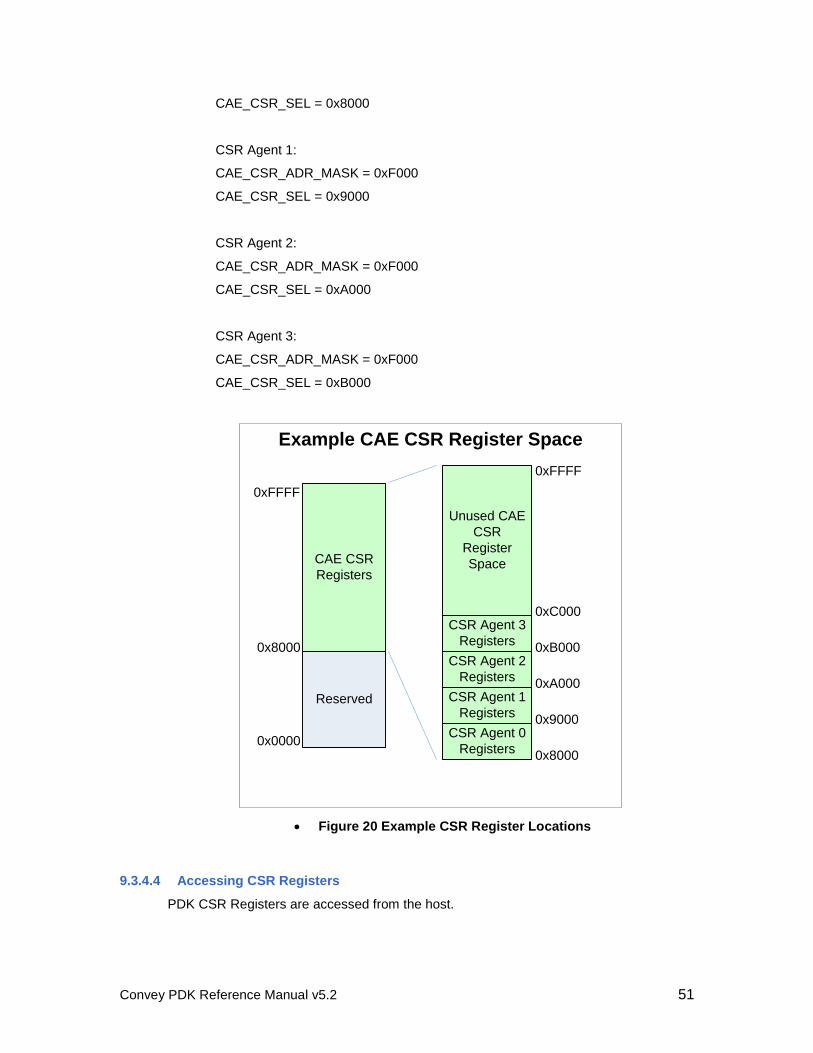
Convey PDK Reference Manual v5.2 51
CAE_CSR_SEL = 0x8000
CSR Agent 1:
CAE_CSR_ADR_MASK = 0xF000
CAE_CSR_SEL = 0x9000
CSR Agent 2:
CAE_CSR_ADR_MASK = 0xF000
CAE_CSR_SEL = 0xA000
CSR Agent 3:
CAE_CSR_ADR_MASK = 0xF000
CAE_CSR_SEL = 0xB000
Example CAE CSR Register Space
CAE CSR
Registers
Reserved
0xFFFF
0x8000
0x0000CSR Agent 0
Registers
CSR Agent 1
Registers
CSR Agent 2
Registers
CSR Agent 3
Registers
Unused CAE
CSR
Register
Space
0x8000
0x9000
0xA000
0xB000
0xC000
0xFFFF
Figure 20 Example CSR Register Locations
9.3.4.4 Accessing CSR Registers
PDK CSR Registers are accessed from the host.
Convey PDK Reference Manual v5.2 52
The host communicates with the MP FPGA via telnet. To establish the telnet connection, type the following commands at the host shell prompt:
/opt/convey/sbin/mpip 2543
telnet local host 2543
Once the telnet session is established, commands can be sent to the MP.
The following commands are used to read and write the AE CSR Registers:
ae_csr_write ae<0-3> <csr address> <value> <mask> where mask is optional
ae_csr_read ae<0-3> <csr address>
When finished, use the telnet escape sequence (normally CTRL-]q) to exit the telnet session, then kill the mpip program.
To kill the mpip program first find the process ID
pgrep mpip
This will return the ID of the process. Then kill the process using
kill <process ID>
An example application program which opens a MP socket, accesses CSR registers then closes the socket is available in the PDK release in the following location:
/opt/convey/pdk/<rev>/<platform>/diag
The example program (ae_perf.c) is used to access the performance monitor registers described in Section 9.3.9.1. This program can be used as a starting point in developing other applications accessing CSRs.
9.3.5 General Resources
9.3.5.1 Static Inputs
Signal Name Type Description
i_aeid<1:0> input AE Identification (0 – 4)
csr_31_31_intlv_dis input Interleave Configuration Indication (boot option)
0: 31/31 Interleave
1: Binary Interleave
Table 18 - Static Signals
The csr_31_31_intlv_dis signal reflects the interleave boot option.
Convey PDK Reference Manual v5.2 53
9.3.5.2 Clocks
The clocks, shown below are generated by a PLL in the AE and are available to the custom personality.
Signal Name Type Description
clk input General 150MHz clock
clk2x input General 300MHz clock
clk_csr input 75MHZ clock for the CSR agent
Table 19 – Clock Signals
The Dispatch and Memory and AE – AE Interfaces to the custom personality use the 150MHz clock. Clocks are phase aligned on the rising edge. These clocks are run through global clock buffers and fanned out across the chip by the Xilinx tools. Any asynchronous crossings must be handled by the FPGA designer. The optional Asynchronous Interface Block described in Section 9.3.8.1 may be instantiated to handle asynchronous crossings.
9.3.5.3 Resets
The reset signals below are available to the custom personality.
Signal Name Type Description
i_reset input Synchronous, power up reset
I_csr_reset_n input Synchronous, active low CSR reset
Table 20 – Reset Signals
The i_reset signal is on a global clock network (connected through a BUFG global clock buffer). This signal can be connected directly to the reset input of flip-flops, or it can be locally fanned out through registers If it is registered locally, it should be connected to the reset input of the flip flop (not the D input) as shown in the figure and the sample code below.
Always @(posedgd clk) begin
if (i_reset)
reset <=1
else
reset<=0
end
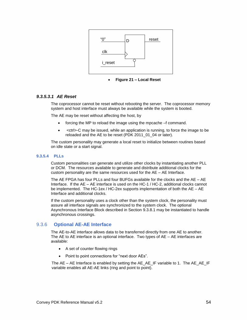
Convey PDK Reference Manual v5.2 54
i_reset
clk
“0” resetD
Figure 21 – Local Reset
9.3.5.3.1 AE Reset
The coprocessor cannot be reset without rebooting the server. The coprocessor memory system and host interface must always be available while the system is booted.
The AE may be reset without affecting the host, by
forcing the MP to reload the image using the mpcache –f command.
<ctrl>-C may be issued, while an application is running, to force the image to be reloaded and the AE to be reset (PDK 2011_01_04 or later).
The custom personality may generate a local reset to initialize between routines based on idle state or a start signal.
9.3.5.4 PLLs
Custom personalities can generate and utilize other clocks by instantiating another PLL or DCM. The resources available to generate and distribute additional clocks for the custom personality are the same resources used for the AE – AE Interface.
The AE FPGA has four PLLs and four BUFGs available for the clocks and the AE – AE Interface. If the AE – AE interface is used on the HC-1 / HC-2, additional clocks cannot be implemented. The HC-1ex / HC-2ex supports implementation of both the AE – AE Interface and additional clocks.
If the custom personality uses a clock other than the system clock, the personality must assure all interface signals are synchronized to the system clock. The optional Asynchronous Interface Block described in Section 9.3.8.1 may be instantiated to handle asynchronous crossings.
9.3.6 Optional AE-AE Interface
The AE-to-AE interface allows data to be transferred directly from one AE to another. The AE to AE interface is an optional interface. Two types of AE – AE interfaces are available:
A set of counter flowing rings
Point to point connections for “next door AEs”.
The AE – AE Interface is enabled by setting the AE_AE_IF variable to 1. The AE_AE_IF variable enables all AE-AE links (ring and point to point).
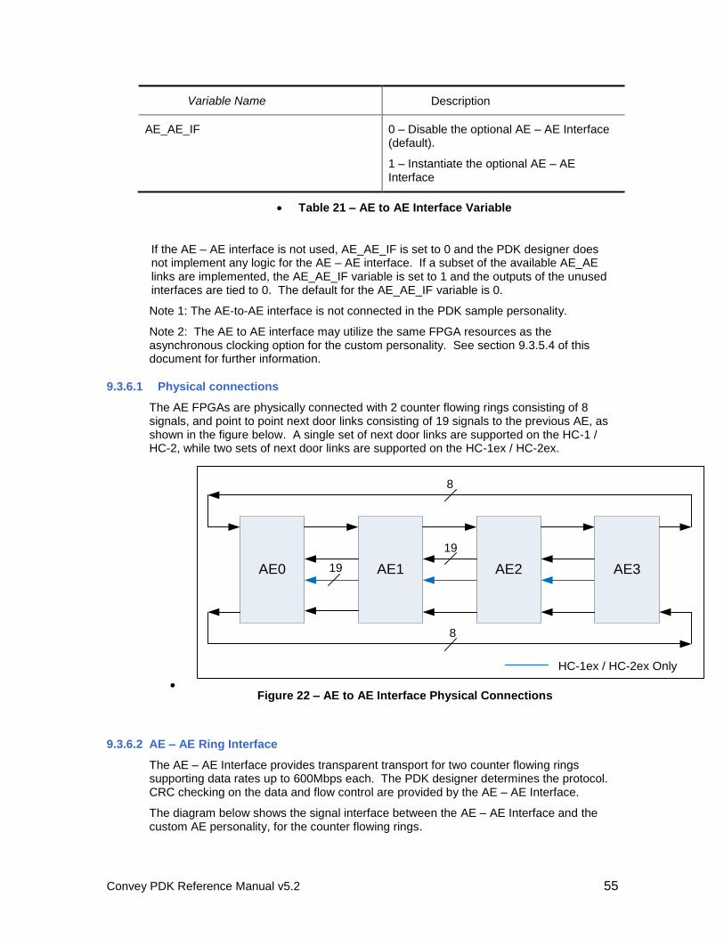
Convey PDK Reference Manual v5.2 55
Variable Name Description
AE_AE_IF 0 – Disable the optional AE – AE Interface (default).
1 – Instantiate the optional AE – AE Interface
Table 21 – AE to AE Interface Variable
If the AE – AE interface is not used, AE_AE_IF is set to 0 and the PDK designer does not implement any logic for the AE – AE interface. If a subset of the available AE_AE links are implemented, the AE_AE_IF variable is set to 1 and the outputs of the unused interfaces are tied to 0. The default for the AE_AE_IF variable is 0.
Note 1: The AE-to-AE interface is not connected in the PDK sample personality.
Note 2: The AE to AE interface may utilize the same FPGA resources as the asynchronous clocking option for the custom personality. See section 9.3.5.4 of this document for further information.
9.3.6.1 Physical connections
The AE FPGAs are physically connected with 2 counter flowing rings consisting of 8 signals, and point to point next door links consisting of 19 signals to the previous AE, as shown in the figure below. A single set of next door links are supported on the HC-1 / HC-2, while two sets of next door links are supported on the HC-1ex / HC-2ex.
AE0 AE1 AE2 AE3
HC-1ex / HC-2ex Only
8
8
19
19
Figure 22 – AE to AE Interface Physical Connections
9.3.6.2 AE – AE Ring Interface
The AE – AE Interface provides transparent transport for two counter flowing rings supporting data rates up to 600Mbps each. The PDK designer determines the protocol. CRC checking on the data and flow control are provided by the AE – AE Interface.
The diagram below shows the signal interface between the AE – AE Interface and the custom AE personality, for the counter flowing rings.
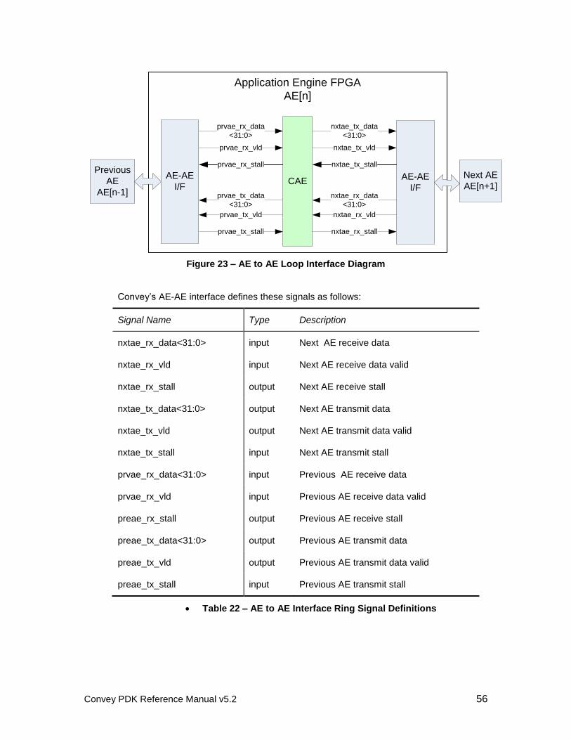
Convey PDK Reference Manual v5.2 56
Application Engine FPGA
AE[n]
AE-AE
I/F
Next AE
AE[n+1]CAE
nxtae_rx_vld
nxtae_rx_data
<31:0>
nxtae_rx_stall
nxtae_tx_vld
nxtae_tx_data
<31:0>
nxtae_tx_stallPrevious
AE
AE[n-1]
AE-AE
I/F
prvae_tx_vld
prvae_tx_data
<31:0>
prvae_tx_stall
prvae_rx_vld
prvae_rx_data
<31:0>
prvae_rx_stall
Figure 23 – AE to AE Loop Interface Diagram
Convey’s AE-AE interface defines these signals as follows:
Signal Name Type Description
nxtae_rx_data<31:0> input Next AE receive data
nxtae_rx_vld input Next AE receive data valid
nxtae_rx_stall output Next AE receive stall
nxtae_tx_data<31:0> output Next AE transmit data
nxtae_tx_vld output Next AE transmit data valid
nxtae_tx_stall input Next AE transmit stall
prvae_rx_data<31:0> input Previous AE receive data
prvae_rx_vld input Previous AE receive data valid
preae_rx_stall output Previous AE receive stall
preae_tx_data<31:0> output Previous AE transmit data
preae_tx_vld output Previous AE transmit data valid
preae_tx_stall input Previous AE transmit stall
Table 22 – AE to AE Interface Ring Signal Definitions
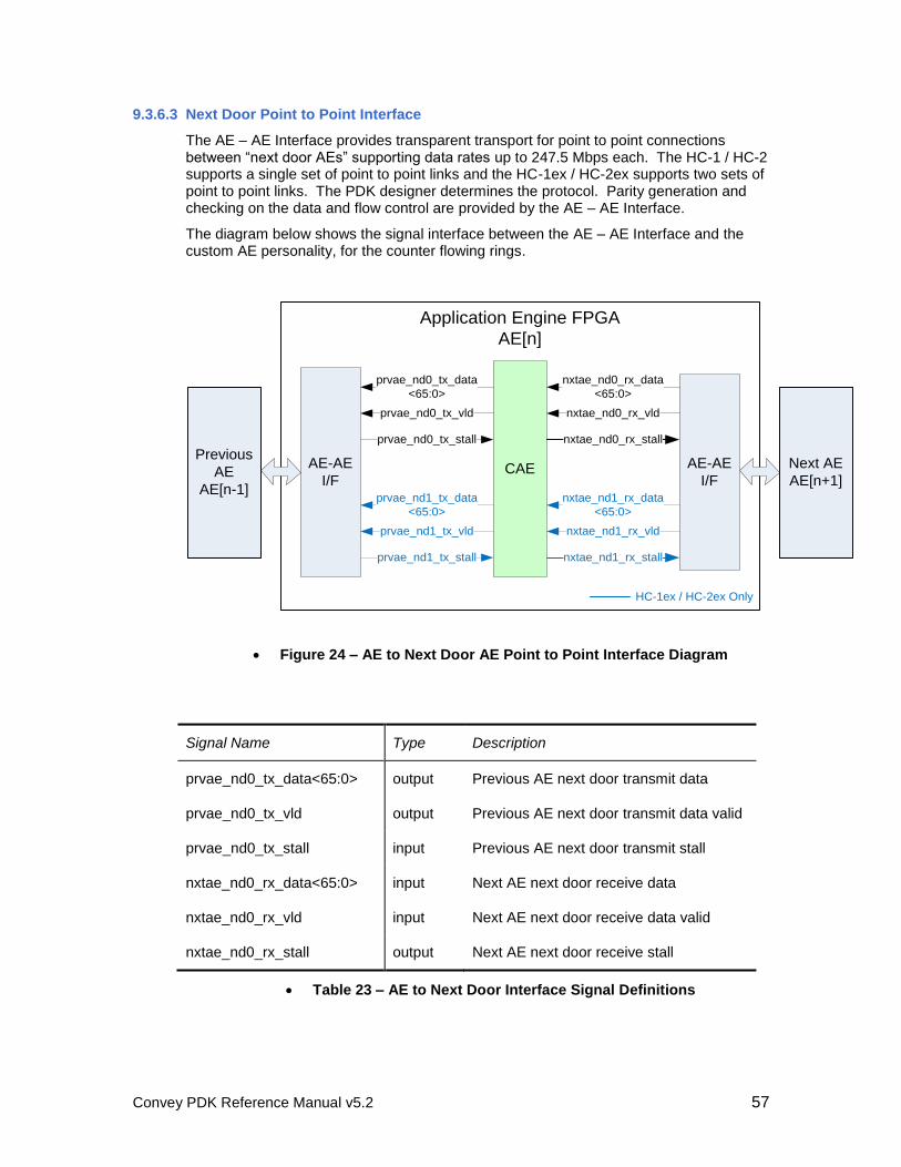
Convey PDK Reference Manual v5.2 57
9.3.6.3 Next Door Point to Point Interface
The AE – AE Interface provides transparent transport for point to point connections between “next door AEs” supporting data rates up to 247.5 Mbps each. The HC-1 / HC-2 supports a single set of point to point links and the HC-1ex / HC-2ex supports two sets of point to point links. The PDK designer determines the protocol. Parity generation and checking on the data and flow control are provided by the AE – AE Interface.
The diagram below shows the signal interface between the AE – AE Interface and the custom AE personality, for the counter flowing rings.
Application Engine FPGA
AE[n]
AE-AE
I/FCAE
nxtae_nd0_rx_vld
nxtae_nd0_rx_data
<65:0>
nxtae_nd0_rx_stall
AE-AE
I/F
prvae_nd1_tx_vld
prvae_nd1_tx_data
<65:0>
prvae_nd1_tx_stall
prvae_nd0_tx_vld
prvae_nd0_tx_data
<65:0>
prvae_nd0_tx_stall
nxtae_nd1_rx_vld
nxtae_nd1_rx_data
<65:0>
nxtae_nd1_rx_stall
HC-1ex / HC-2ex Only
Previous
AE
AE[n-1]
Next AE
AE[n+1]
Figure 24 – AE to Next Door AE Point to Point Interface Diagram
Signal Name Type Description
prvae_nd0_tx_data<65:0> output Previous AE next door transmit data
prvae_nd0_tx_vld output Previous AE next door transmit data valid
prvae_nd0_tx_stall input Previous AE next door transmit stall
nxtae_nd0_rx_data<65:0> input Next AE next door receive data
nxtae_nd0_rx_vld input Next AE next door receive data valid
nxtae_nd0_rx_stall output Next AE next door receive stall
Table 23 – AE to Next Door Interface Signal Definitions
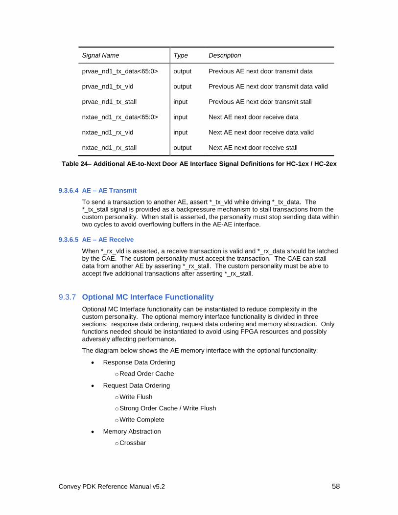
Convey PDK Reference Manual v5.2 58
Signal Name Type Description
prvae_nd1_tx_data<65:0> output Previous AE next door transmit data
prvae_nd1_tx_vld output Previous AE next door transmit data valid
prvae_nd1_tx_stall input Previous AE next door transmit stall
nxtae_nd1_rx_data<65:0> input Next AE next door receive data
nxtae_nd1_rx_vld input Next AE next door receive data valid
nxtae_nd1_rx_stall output Next AE next door receive stall
Table 24– Additional AE-to-Next Door AE Interface Signal Definitions for HC-1ex / HC-2ex
9.3.6.4 AE – AE Transmit
To send a transaction to another AE, assert *_tx_vld while driving *_tx_data. The *_tx_stall signal is provided as a backpressure mechanism to stall transactions from the custom personality. When stall is asserted, the personality must stop sending data within two cycles to avoid overflowing buffers in the AE-AE interface.
9.3.6.5 AE – AE Receive
When *_rx_vld is asserted, a receive transaction is valid and *_rx_data should be latched by the CAE. The custom personality must accept the transaction. The CAE can stall data from another AE by asserting *_rx_stall. The custom personality must be able to accept five additional transactions after asserting *_rx_stall.
9.3.7 Optional MC Interface Functionality
Optional MC Interface functionality can be instantiated to reduce complexity in the custom personality. The optional memory interface functionality is divided in three sections: response data ordering, request data ordering and memory abstraction. Only functions needed should be instantiated to avoid using FPGA resources and possibly adversely affecting performance.
The diagram below shows the AE memory interface with the optional functionality:
Response Data Ordering
o Read Order Cache
Request Data Ordering
o Write Flush
o Strong Order Cache / Write Flush
o Write Complete
Memory Abstraction
o Crossbar
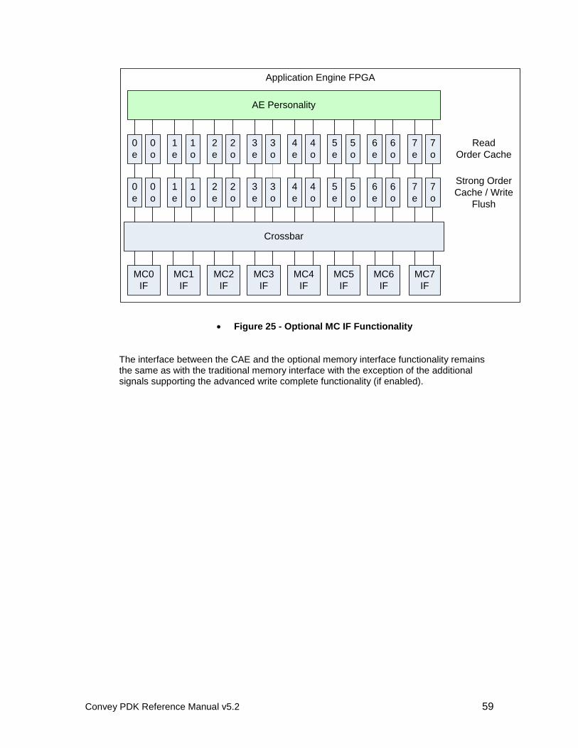
Convey PDK Reference Manual v5.2 59
Application Engine FPGA
MC0
IF
MC1
IF
MC2
IF
MC3
IF
MC4
IF
MC5
IF
MC6
IF
Crossbar
MC7
IF
Strong Order
Cache / Write
Flush
0
e
0
o
1
e
1
o
2
e
2
o
3
e
3
o
4
e
4
o
5
e
5
o
6
e
6
o
7
e
7
o
Read
Order Cache
AE Personality
0
e
0
o
1
e
1
o
2
e
2
o
3
e
3
o
4
e
4
o
5
e
5
o
6
e
6
o
7
e
7
o
Figure 25 - Optional MC IF Functionality
The interface between the CAE and the optional memory interface functionality remains the same as with the traditional memory interface with the exception of the additional signals supporting the advanced write complete functionality (if enabled).

Convey PDK Reference Manual v5.2 60
Application Engine FPGA
CAE
MC I/F
(x8)
Even
Resp
port
XBAR
SO/
WF (e)
(x8)
RDOe
(x8) Even
Req
port
Request (even)
Response (even)
SO/
WF (o)
(x8)
RDOo
(x8)Request (odd)
Response (odd)
Odd
Req
port
Odd
Resp
port
Figure 26 - High Level Interface for Optional MC Functionality
9.3.7.1 Optional Read Order Cache MC Interface
The optional read order cache assures memory reads (loads) from the associated request port are returned to the custom personality in order. The read data and read control information returned from memory is queued and ordered before being returned to the personality. Order is only assured for reads and only between requests from the same request port.
The Read Order Cache does not impact memory content. The order of reads and writes is not affected, so addition additional functionality may need to be implemented in the personality or instantiated in the memory interface, to assure request data order.
The read order cache is enabled using the MC_READ_ORDER variable.
Variable Name Description
MC_READ_ORDER 0 – Disable the optional read order cache (default).
1 – Instantiate the optional read order cache
Table 25 – Read Order Cache Variable
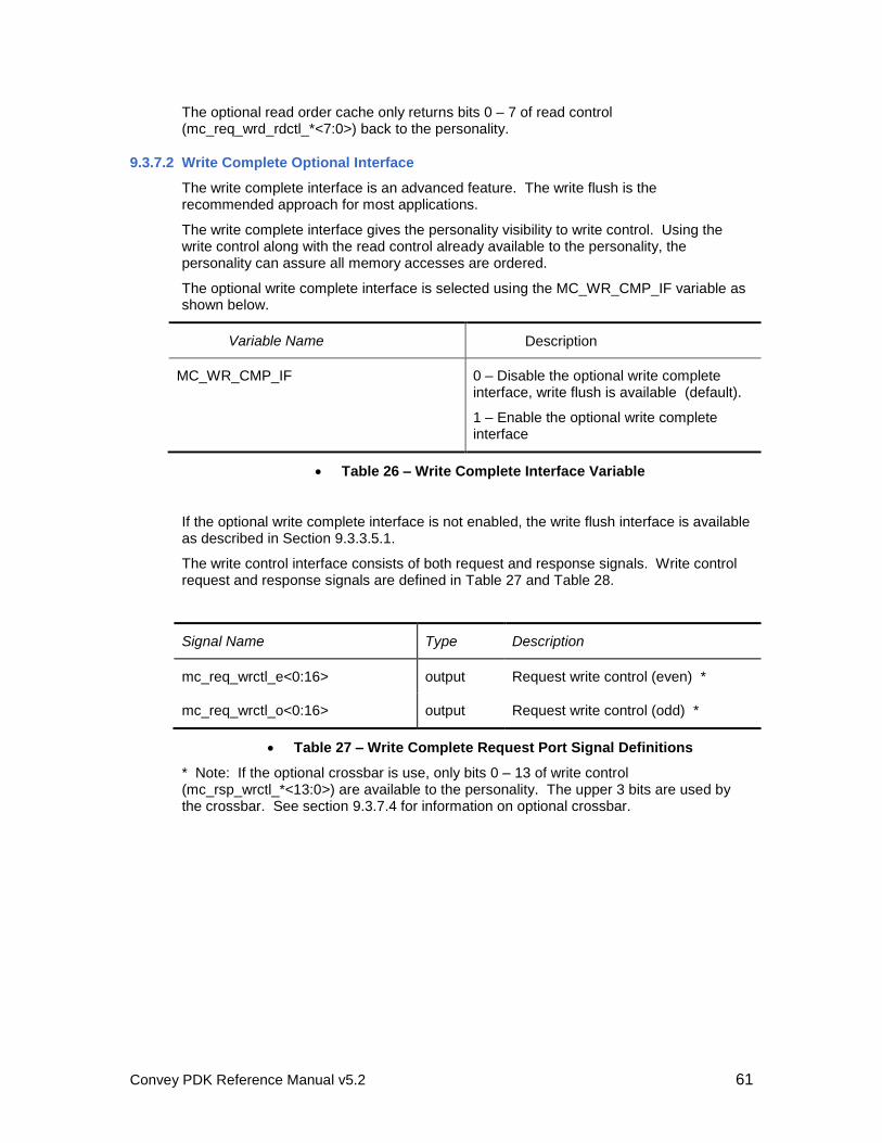
Convey PDK Reference Manual v5.2 61
The optional read order cache only returns bits 0 – 7 of read control (mc_req_wrd_rdctl_*<7:0>) back to the personality.
9.3.7.2 Write Complete Optional Interface
The write complete interface is an advanced feature. The write flush is the recommended approach for most applications.
The write complete interface gives the personality visibility to write control. Using the write control along with the read control already available to the personality, the personality can assure all memory accesses are ordered.
The optional write complete interface is selected using the MC_WR_CMP_IF variable as shown below.
Variable Name Description
MC_WR_CMP_IF 0 – Disable the optional write complete interface, write flush is available (default).
1 – Enable the optional write complete interface
Table 26 – Write Complete Interface Variable
If the optional write complete interface is not enabled, the write flush interface is available as described in Section 9.3.3.5.1.
The write control interface consists of both request and response signals. Write control request and response signals are defined in Table 27 and Table 28.
Signal Name Type Description
mc_req_wrctl_e<0:16> output Request write control (even) *
mc_req_wrctl_o<0:16> output Request write control (odd) *
Table 27 – Write Complete Request Port Signal Definitions
* Note: If the optional crossbar is use, only bits 0 – 13 of write control (mc_rsp_wrctl_*<13:0>) are available to the personality. The upper 3 bits are used by the crossbar. See section 9.3.7.4 for information on optional crossbar.
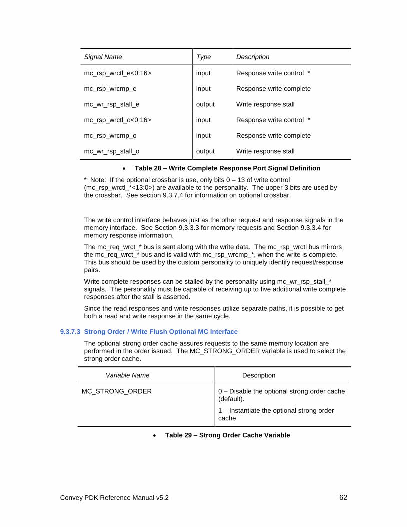
Convey PDK Reference Manual v5.2 62
Signal Name Type Description
mc_rsp_wrctl_e<0:16> input Response write control *
mc_rsp_wrcmp_e input Response write complete
mc_wr_rsp_stall_e output Write response stall
mc_rsp_wrctl_o<0:16> input Response write control *
mc_rsp_wrcmp_o input Response write complete
mc_wr_rsp_stall_o output Write response stall
Table 28 – Write Complete Response Port Signal Definition
* Note: If the optional crossbar is use, only bits 0 – 13 of write control (mc_rsp_wrctl_*<13:0>) are available to the personality. The upper 3 bits are used by the crossbar. See section 9.3.7.4 for information on optional crossbar.
The write control interface behaves just as the other request and response signals in the memory interface. See Section 9.3.3.3 for memory requests and Section 9.3.3.4 for memory response information.
The mc_req_wrct_* bus is sent along with the write data. The mc_rsp_wrctl bus mirrors the mc_req_wrct_* bus and is valid with mc_rsp_wrcmp_*, when the write is complete. This bus should be used by the custom personality to uniquely identify request/response pairs.
Write complete responses can be stalled by the personality using mc_wr_rsp_stall_* signals. The personality must be capable of receiving up to five additional write complete responses after the stall is asserted.
Since the read responses and write responses utilize separate paths, it is possible to get both a read and write response in the same cycle.
9.3.7.3 Strong Order / Write Flush Optional MC Interface
The optional strong order cache assures requests to the same memory location are performed in the order issued. The MC_STRONG_ORDER variable is used to select the strong order cache.
Variable Name Description
MC_STRONG_ORDER 0 – Disable the optional strong order cache (default).
1 – Instantiate the optional strong order cache
Table 29 – Strong Order Cache Variable
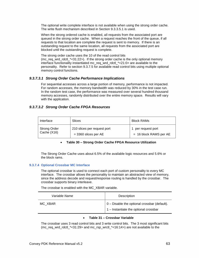
Convey PDK Reference Manual v5.2 63
The optional write complete interface is not available when using the strong order cache. The write flush mechanism described in Section 9.3.3.5.1 is used.
When the strong ordered cache is enabled, all requests from the associated port are queued in the strong order cache. When a request reaches the front of the queue, if all requests to that location are complete the request is sent to memory. If there is an outstanding request to the same location, all requests from the associated port are blocked until the outstanding request is complete.
The strong order cache uses the 10 of the read control bits (mc_req_wrd_rdctl_*<31:22>). If the strong order cache is the only optional memory interface functionality instantiated mc_req_wrd_rdctl_*<21:0> are available to the personality. Refer to section 9.3.7.5 for available read control bits using multiple optional memory control functions.
9.3.7.3.1 Strong Order Cache Performance Implications
For sequential accesses across a large portion of memory, performance is not impacted. For random accesses, the memory bandwidth was reduced by 30% in the test case run. In the random test case, the performance was measured over several hundred thousand memory accesses, randomly distributed over the entire memory space. Results will vary with the application.
9.3.7.3.2 Strong Order Cache FPGA Resources
Interface Slices Block RAMs
Strong Order Cache (X16)
210 slices per request port
= 3360 slices per AE
1 per request port
= 16 block RAMS per AE
Table 30 – Strong Order Cache FPGA Resource Utilization
The Strong Order Cache uses about 6.5% of the available logic resources and 5.6% or the block rams.
9.3.7.4 Optional Crossbar MC Interface
The optional crossbar is used to connect each port of custom personality to every MC interface. The crossbar allows the personality to maintain an abstracted view of memory, since the address decode and request/response routing is handled by the crossbar. The crossbar supports binary interleave.
The crossbar is enabled with the MC_XBAR variable.
Variable Name Description
MC_XBAR 0 – Disable the optional crossbar (default).
1 – Instantiate the optional crossbar
Table 31 – Crossbar Variable
The crossbar uses 3 read control bits and 3 write control bits. The 3 most significant bits (mc_req_wrd_rdctl_*<31:29> and mc_rsp_wrctl_*<16:14>) are not available to the
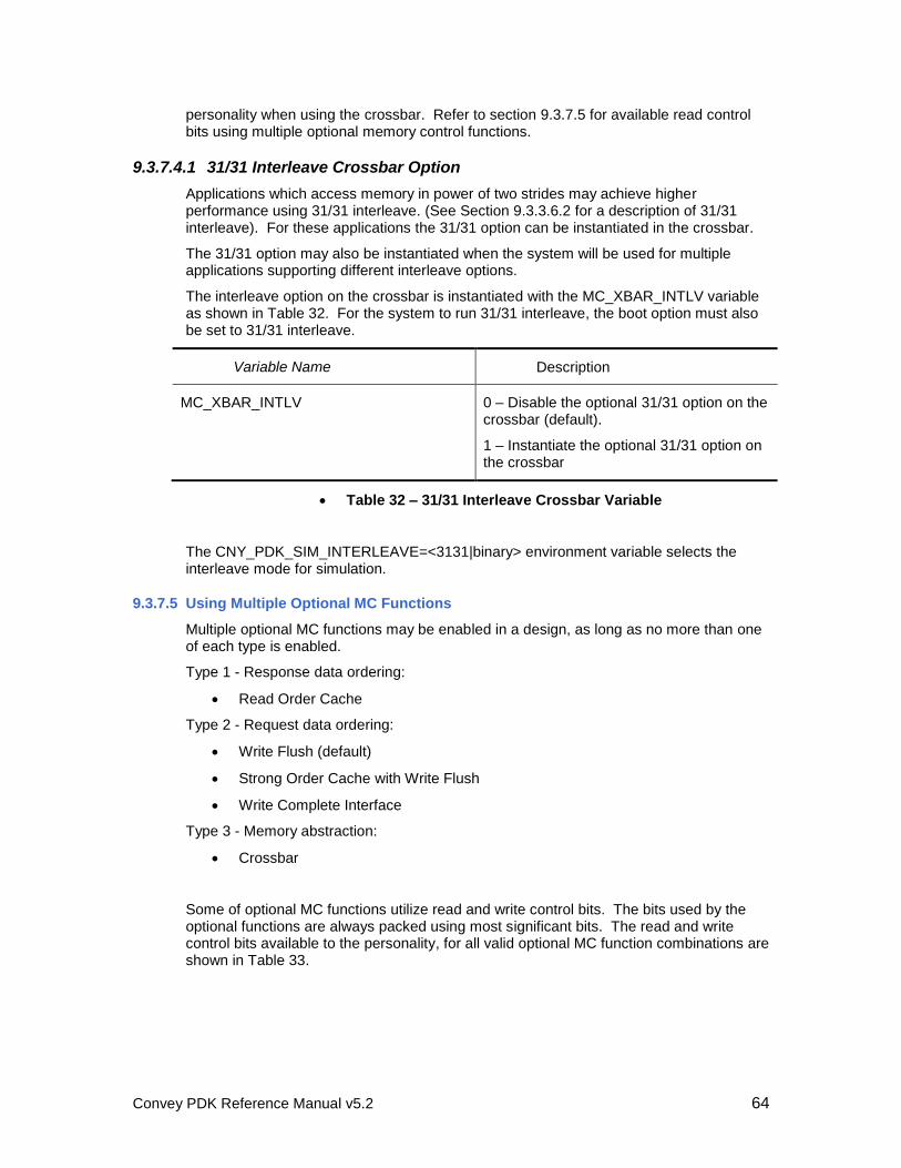
Convey PDK Reference Manual v5.2 64
personality when using the crossbar. Refer to section 9.3.7.5 for available read control bits using multiple optional memory control functions.
9.3.7.4.1 31/31 Interleave Crossbar Option
Applications which access memory in power of two strides may achieve higher performance using 31/31 interleave. (See Section 9.3.3.6.2 for a description of 31/31 interleave). For these applications the 31/31 option can be instantiated in the crossbar.
The 31/31 option may also be instantiated when the system will be used for multiple applications supporting different interleave options.
The interleave option on the crossbar is instantiated with the MC_XBAR_INTLV variable as shown in Table 32. For the system to run 31/31 interleave, the boot option must also be set to 31/31 interleave.
Variable Name Description
MC_XBAR_INTLV 0 – Disable the optional 31/31 option on the crossbar (default).
1 – Instantiate the optional 31/31 option on the crossbar
Table 32 – 31/31 Interleave Crossbar Variable
The CNY_PDK_SIM_INTERLEAVE=<3131|binary> environment variable selects the interleave mode for simulation.
9.3.7.5 Using Multiple Optional MC Functions
Multiple optional MC functions may be enabled in a design, as long as no more than one of each type is enabled.
Type 1 - Response data ordering:
Read Order Cache
Type 2 - Request data ordering:
Write Flush (default)
Strong Order Cache with Write Flush
Write Complete Interface
Type 3 - Memory abstraction:
Crossbar
Some of optional MC functions utilize read and write control bits. The bits used by the optional functions are always packed using most significant bits. The read and write control bits available to the personality, for all valid optional MC function combinations are shown in Table 33.
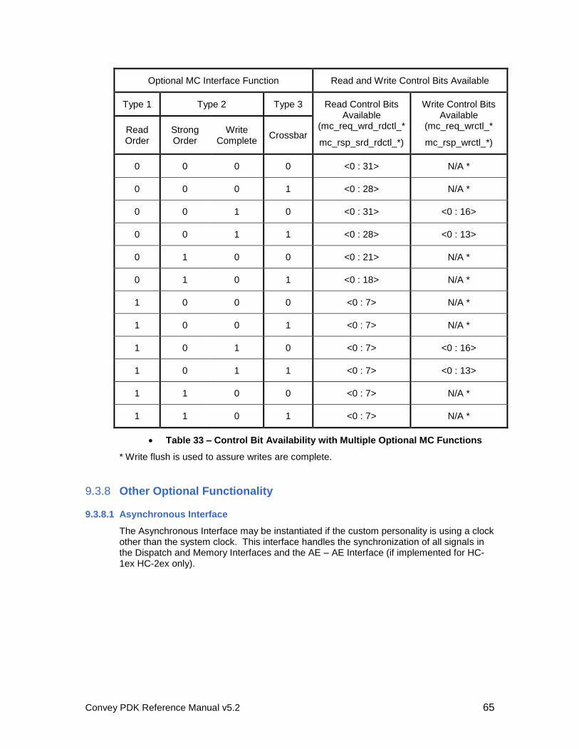
Convey PDK Reference Manual v5.2 65
Optional MC Interface Function Read and Write Control Bits Available
Type 1 Type 2 Type 3 Read Control Bits Available
(mc_req_wrd_rdctl_*
mc_rsp_srd_rdctl_*)
Write Control Bits Available
(mc_req_wrctl_*
mc_rsp_wrctl_*)
Read Order
Strong Order
Write Complete
Crossbar
0 0 0 0 <0 : 31> N/A *
0 0 0 1 <0 : 28> N/A *
0 0 1 0 <0 : 31> <0 : 16>
0 0 1 1 <0 : 28> <0 : 13>
0 1 0 0 <0 : 21> N/A *
0 1 0 1 <0 : 18> N/A *
1 0 0 0 <0 : 7> N/A *
1 0 0 1 <0 : 7> N/A *
1 0 1 0 <0 : 7> <0 : 16>
1 0 1 1 <0 : 7> <0 : 13>
1 1 0 0 <0 : 7> N/A *
1 1 0 1 <0 : 7> N/A *
Table 33 – Control Bit Availability with Multiple Optional MC Functions
* Write flush is used to assure writes are complete.
9.3.8 Other Optional Functionality
9.3.8.1 Asynchronous Interface
The Asynchronous Interface may be instantiated if the custom personality is using a clock other than the system clock. This interface handles the synchronization of all signals in the Dispatch and Memory Interfaces and the AE – AE Interface (if implemented for HC-1ex HC-2ex only).
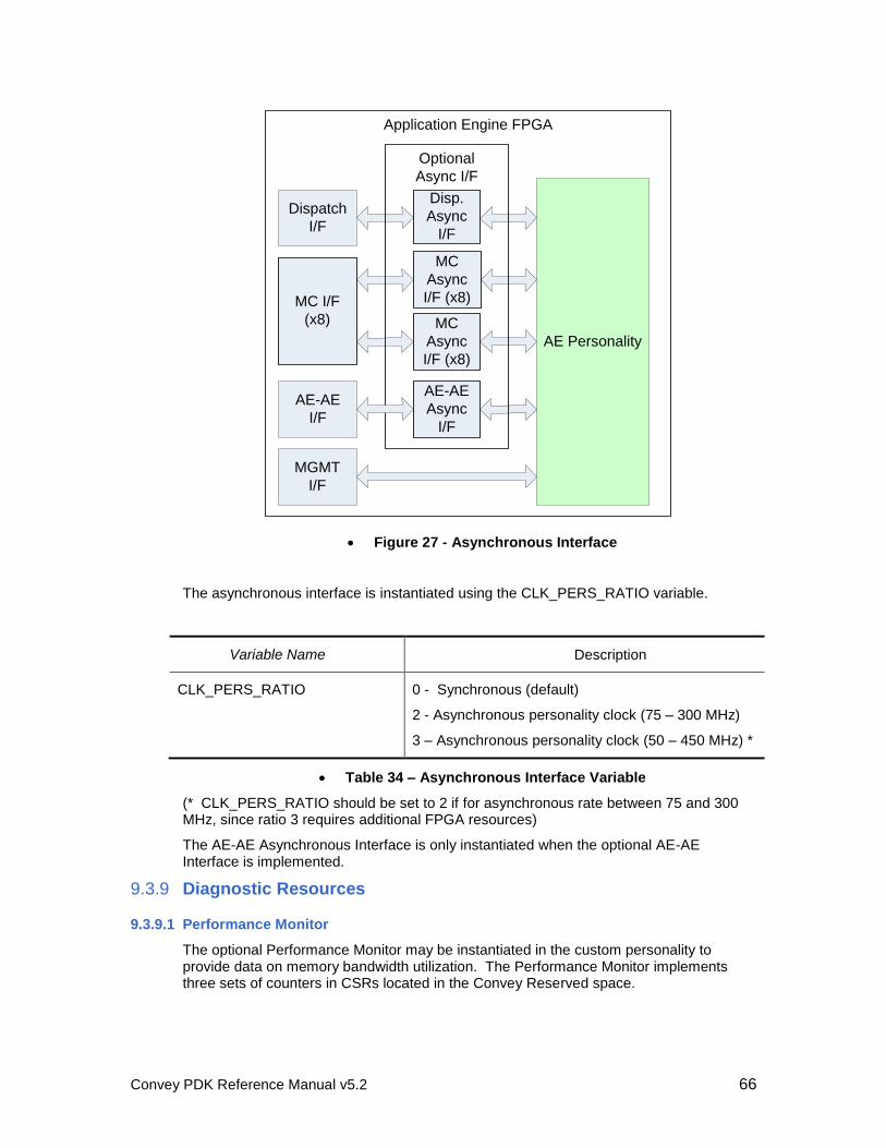
Convey PDK Reference Manual v5.2 66
AE-AE
I/F
Dispatch
I/F
MGMT
I/F
AE Personality
Disp.
Async
I/F
MC
Async
I/F (x8)
MC
Async
I/F (x8)
MC I/F
(x8)
AE-AE
Async
I/F
Optional
Async I/F
Application Engine FPGA
Figure 27 - Asynchronous Interface
The asynchronous interface is instantiated using the CLK_PERS_RATIO variable.
Variable Name Description
CLK_PERS_RATIO 0 - Synchronous (default)
2 - Asynchronous personality clock (75 – 300 MHz)
3 – Asynchronous personality clock (50 – 450 MHz) *
Table 34 – Asynchronous Interface Variable
(* CLK_PERS_RATIO should be set to 2 if for asynchronous rate between 75 and 300 MHz, since ratio 3 requires additional FPGA resources)
The AE-AE Asynchronous Interface is only instantiated when the optional AE-AE Interface is implemented.
9.3.9 Diagnostic Resources
9.3.9.1 Performance Monitor
The optional Performance Monitor may be instantiated in the custom personality to provide data on memory bandwidth utilization. The Performance Monitor implements three sets of counters in CSRs located in the Convey Reserved space.
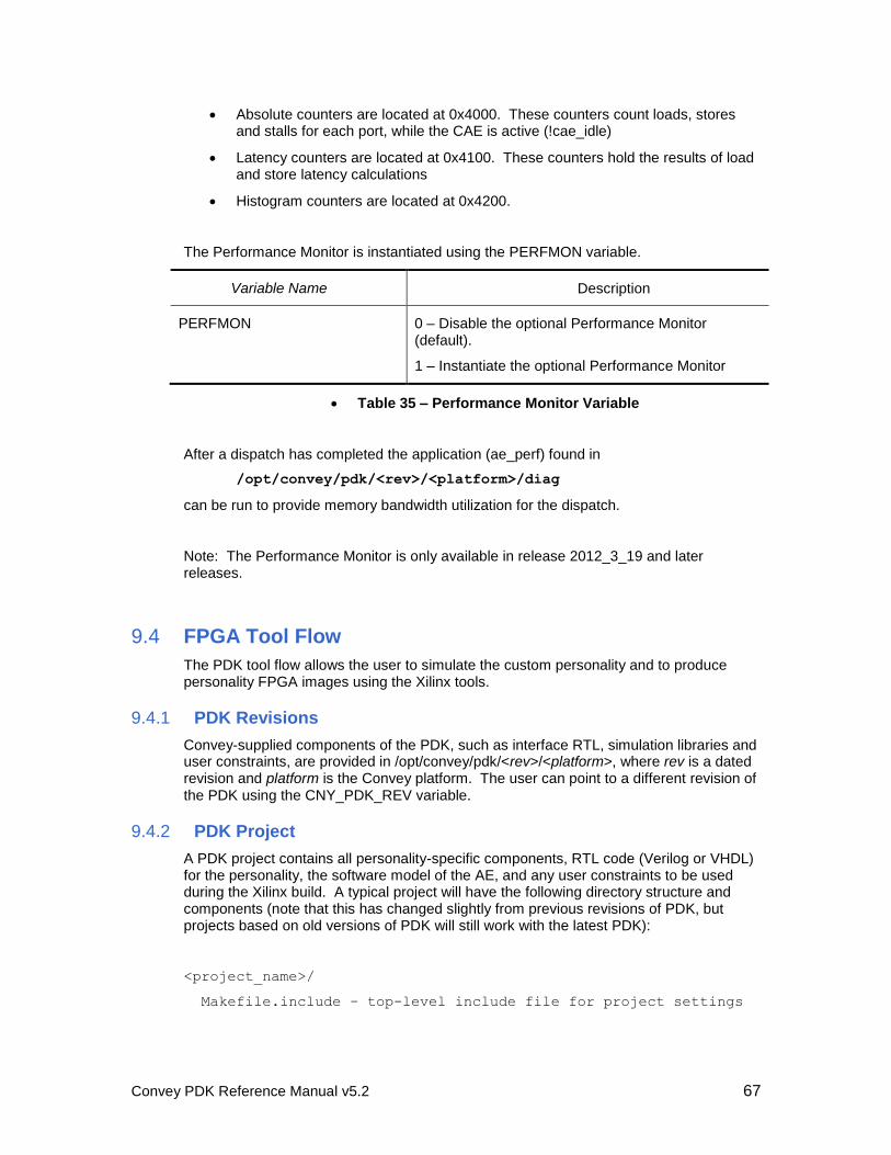
Convey PDK Reference Manual v5.2 67
Absolute counters are located at 0x4000. These counters count loads, stores and stalls for each port, while the CAE is active (!cae_idle)
Latency counters are located at 0x4100. These counters hold the results of load and store latency calculations
Histogram counters are located at 0x4200.
The Performance Monitor is instantiated using the PERFMON variable.
Variable Name Description
PERFMON 0 – Disable the optional Performance Monitor (default).
1 – Instantiate the optional Performance Monitor
Table 35 – Performance Monitor Variable
After a dispatch has completed the application (ae_perf) found in
/opt/convey/pdk/<rev>/<platform>/diag
can be run to provide memory bandwidth utilization for the dispatch.
Note: The Performance Monitor is only available in release 2012_3_19 and later releases.
9.4 FPGA Tool Flow
The PDK tool flow allows the user to simulate the custom personality and to produce personality FPGA images using the Xilinx tools.
9.4.1 PDK Revisions
Convey-supplied components of the PDK, such as interface RTL, simulation libraries and user constraints, are provided in /opt/convey/pdk/<rev>/<platform>, where rev is a dated revision and platform is the Convey platform. The user can point to a different revision of the PDK using the CNY_PDK_REV variable.
9.4.2 PDK Project
A PDK project contains all personality-specific components, RTL code (Verilog or VHDL) for the personality, the software model of the AE, and any user constraints to be used during the Xilinx build. A typical project will have the following directory structure and components (note that this has changed slightly from previous revisions of PDK, but projects based on old versions of PDK will still work with the latest PDK):
<project_name>/
Makefile.include – top-level include file for project settings
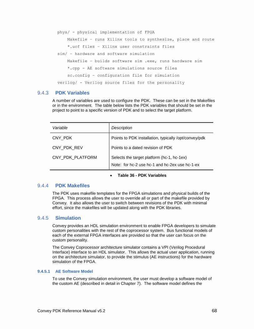
Convey PDK Reference Manual v5.2 68
phys/ - physical implementation of FPGA
Makefile – runs Xilinx tools to synthesize, place and route
*.ucf files – Xilinx user constraints files
sim/ – hardware and software simulation
Makefile – builds software sim .exe, runs hardware sim
*.cpp - AE software simulations source files
sc.config – configuration file for simulation
verilog/ - Verilog source files for the personality
9.4.3 PDK Variables
A number of variables are used to configure the PDK. These can be set in the Makefiles or in the environment. The table below lists the PDK variables that should be set in the project to point to a specific version of PDK and to select the target platform.
Variable Description
CNY_PDK Points to PDK installation, typically /opt/convey/pdk
CNY_PDK_REV Points to a dated revision of PDK
CNY_PDK_PLATFORM Selects the target platform (hc-1, hc-1ex)
Note: for hc-2 use hc-1 and hc-2ex use hc-1-ex
Table 36 - PDK Variables
9.4.4 PDK Makefiles
The PDK uses makefile templates for the FPGA simulations and physical builds of the FPGA. This process allows the user to override all or part of the makefile provided by Convey. It also allows the user to switch between revisions of the PDK with minimal effort, since the makefiles will be updated along with the PDK libraries.
9.4.5 Simulation
Convey provides an HDL simulation environment to enable FPGA developers to simulate custom personalities with the rest of the coprocessor system. Bus functional models of each of the external FPGA interfaces are provided so that the user can focus on the custom personality.
The Convey Coprocessor architecture simulator contains a VPI (Verilog Procedural Interface) interface to an HDL simulator. This allows the actual user application, running on the architecture simulator, to provide the stimulus (AE instructions) for the hardware simulation of the FPGA.
9.4.5.1 AE Software Model
To use the Convey simulation environment, the user must develop a software model of the custom AE (described in detail in Chapter 7). The software model defines the
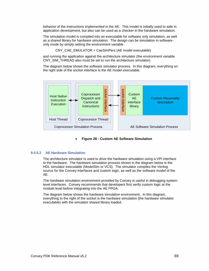
Convey PDK Reference Manual v5.2 69
behavior of the instructions implemented in the AE. This model is initially used to aide in application development, but also can be used as a checker in the hardware simulation.
The simulation model is compiled into an executable for software only simulation, as well as a shared library for hardware simulation. The design can be simulation in software-only mode by simply setting the environment variable
CNY_CAE_EMULATOR = CaeSimPers (AE model executable)
and running the application against the architecture simulator (the environment variable CNY_SIM_THREAD also must be set to run the architecture simulator).
The diagram below shows the software simulator process. In this diagram, everything on the right side of the socket interface is the AE model executable.
Coprocessor Simulation Process
Coprocessor ThreadHost Thread
Host Native
Instruction
Execution
Coprocessor
Dispatch and
Canonical
Instructionsso
cke
t inte
rface
AE Software Simulation Process
Custom
AE
interface
library
so
cke
t inte
rface
Custom Personality
description
Figure 28 - Custom AE Software Simulation
9.4.5.2 AE Hardware Simulation
The architecture simulator is used to drive the hardware simulation using a VPI interface to the hardware. The hardware simulation process shown in the diagram below is the HDL simulator executable (ModelSim or VCS). The simulator compiles the Verilog source for the Convey interfaces and custom logic, as well as the software model of the AE.
The hardware simulation environment provided by Convey is useful in debugging system-level interfaces. Convey recommends that developers first verify custom logic at the module level before integrating into the AE FPGA.
The diagram below shows the hardware simulation environment. In this diagram, everything to the right of the socket is the hardware simulation (the hardware simulator executable) with the simulator shared library loaded.
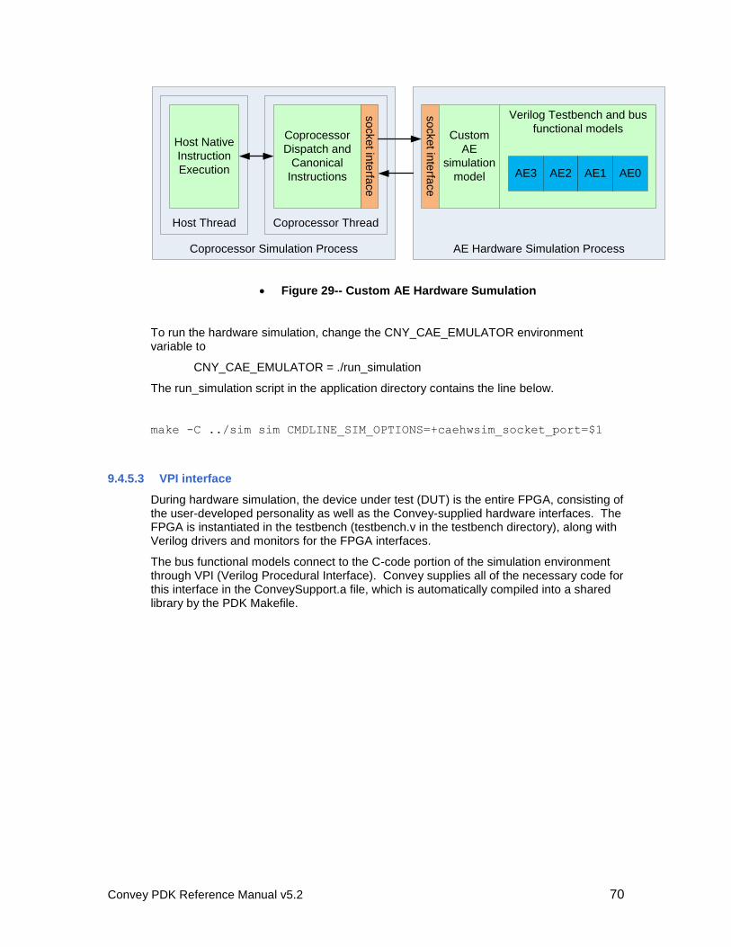
Convey PDK Reference Manual v5.2 70
AE Hardware Simulation Process
Verilog Testbench and bus
functional models
so
cke
t inte
rface
AE3 AE2 AE1 AE0
Custom
AE
simulation
model
Coprocessor Simulation Process
Coprocessor ThreadHost Thread
Host Native
Instruction
Execution
Coprocessor
Dispatch and
Canonical
Instructions
so
cke
t inte
rface
Figure 29-- Custom AE Hardware Sumulation
To run the hardware simulation, change the CNY_CAE_EMULATOR environment variable to
CNY_CAE_EMULATOR = ./run_simulation
The run_simulation script in the application directory contains the line below.
make -C ../sim sim CMDLINE_SIM_OPTIONS=+caehwsim_socket_port=$1
9.4.5.3 VPI interface
During hardware simulation, the device under test (DUT) is the entire FPGA, consisting of the user-developed personality as well as the Convey-supplied hardware interfaces. The FPGA is instantiated in the testbench (testbench.v in the testbench directory), along with Verilog drivers and monitors for the FPGA interfaces.
The bus functional models connect to the C-code portion of the simulation environment through VPI (Verilog Procedural Interface). Convey supplies all of the necessary code for this interface in the ConveySupport.a file, which is automatically compiled into a shared library by the PDK Makefile.
Convey PDK Reference Manual v5.2 71
Architecture
Simulator
AE Hardware Simulation Process
Verilog Testbench and bus
functional models
Simulated
AE[n]
instruction
dispatch
Memory
requests
ConveyPDK.so
Custom personality
model
(Emulated AEs)
Custom AE
interface library
(ConveySupport.a)
so
cke
t inte
rface VPI
Interface
Figure 30 - Hardware Simulation Detail
9.4.5.4 Configuration
The sc.config file (in the project sim or testbench directory) contains configuration settings for the hardware simulation. This file is read when the simulation starts.
9.4.5.4.1 CaeSim settings
The line beginning with “caesim” contains settings for the Custom AE (CAE) software model:
#######################################################################
# CaeSim Setup Arguments: debug checker_mode
########################################################################
caesim 2 0
The first number is the debug level, which changes the verbosity of the output from the simulation. Debug level 0 is the least verbose, reporting only errors, while level 3 shows all debug messages.
The second field is the checker_mode field, which can have the following values:
Convey PDK Reference Manual v5.2 72
checker_mode Description
0 Software model and checker enabled
1 Software model and checker disabled
2 Reserved
3 Software model enabled, checker disabled
Table 37 - Simulation checker mode
9.4.5.5 Hardware Simulation Checking
The user-supplied software model is used as a checker for the hardware simulation by providing expected data for memory transactions and AEG register data. The software model of the AE serves as the “golden model,” and all transactions from the simulated AE hardware model are compared against transactions from the software model. Two interfaces are checked: scalar return data from the AE in the dispatch interface, and memory load and store requests from the AE.
Because scalar returns from the AE to the AEH must be ordered, checking is simply done by storing scalar data from the software model in a FIFO. When scalar data is received by the AE-to-AEH monitor in the hardware simulation, the value is compared with the next value in the FIFO. An error is asserted if the values don’t match.
Memory transactions are checked using the address as the key. Memory state is maintained in the architecture simulator thread. When a load request is sent from the AE model, the returned value is cached along with the address and transaction size. When a load request to the same address is received from the hardware model, the cached data is returned and the transaction is removed from the list.
When a store request is sent from the AE software model, the address, data and size are saved as with load requests. The store is sent to the simulator thread. When a store to the same address is received from the hardware model, the data is checked against the cached expected data.
The user should be aware that because of the use of the software model as a checker, data stored by the software model is sent to the architecture simulator (and seen by the application).
There may be cases in which the user wants to disable the checking feature. This can be done by changing the checker_mode value in the sc.config file.
9.4.5.6 Simulation Makefile
The user’s testbench directory should contain a Makefile that includes Convey’s makefile template (or a project include file that includes the template). An example of the user Makefile is below.
# To compile additional verilog modules for simulation:
# CNY_PDK_TB_USER_VLOG += tb_user.v

Convey PDK Reference Manual v5.2 73
# To fix the seed for simulation:
# CNY_PDK_SIM_SEED = 11223344
#################################################################
#
# Include Convey Makefile Template
#################################################################
#
include ../Makefile.include
Note in the above example that the Makefile.include is at the project top level and includes the PDK Makefile template.
9.4.5.7 Simulation Environment Variables
Convey’s simulation environment requires the following environment variables to be set by the user:
CNY_PDK_HDLSIM = (Synopsys|Mentor)
9.4.6 Xilinx Tool Flow
As part of the PDK, Convey provides an environment to ease the process of implementing the AE FPGA with Xilinx tools. The Xilinx development process and tool flow is documented in detail in the Xilinx ISE Software Manuals, which can be downloaded from www.xilinx.com.
9.4.6.1 Xilinx Project File
The Xilinx tools use a project file <design>.prj to identify the source files used in the design. Many of these are provided by Convey in the PDK. Others are developed by the user and exist in the user’s project tree.
Convey’s makefile automatically generates a project file if one doesn’t already exist in the project phys directory. The script first looks in the default project verilog folder <project>/verilog and its subdirectories for files with a ‘.v’ extension. It also looks for user code in the <project>/coregen directory. Using make file variables the user can specify alternate locations for source files.
If new source files are created after the project is created, the user should run
make clean
in the project phys directory, so the project file will be regenerated to include the new source files.
9.4.6.2 Physical Makefile
Convey provides a templated physical Makefile to build the AE FPGA. The user project should contain a Makefile in the phys directory that includes the PDK Makefile:
Convey PDK Reference Manual v5.2 74
#################################################################
#
# Include Convey Makefile Template
#################################################################
#
include ../Makefile.include
The Xilinx project file (cae_fpga.prj) will be automatically generated by the make process if the file does not exist. If the user makes a local copy of any of the Convey-supplied logic libraries, it may be necessary to edit this file to remove the duplicate entry.
9.4.6.3 User Constraints Files
Convey provides all constraints necessary for Convey interfaces. These files are part of the PDK RPM and are automatically used when the physical Makefile is run. Constraints for the custom personality should be added by the user in the project phys directory. Each *.ucf file should be added to the Makefile using the UCF_FILES variable:
UCF_FILES += <file1>.ucf
UCF_FILES += <file2>.ucf
Note that the += is used to add each file to the list rather than over-writing it.
9.4.6.4 HC-1 / HC-2 FPGA Resources
The Application Engines in the HC-1 and HC-2 platforms are implemented in Xilinx Virtex 5 LX330 FPGAs. The required Convey hardware interfaces—the dispatch interface, CSR interfaces and MC interfaces—use about 10% of the available logic resources and about 25% of the block rams.
The dispatch interface is located in the center of the chip. The MC interfaces are on the left and right sides of the FPGA, and the MC CSR interfaces are in the corners of the part. The figure below shows the FPGA floor plan.
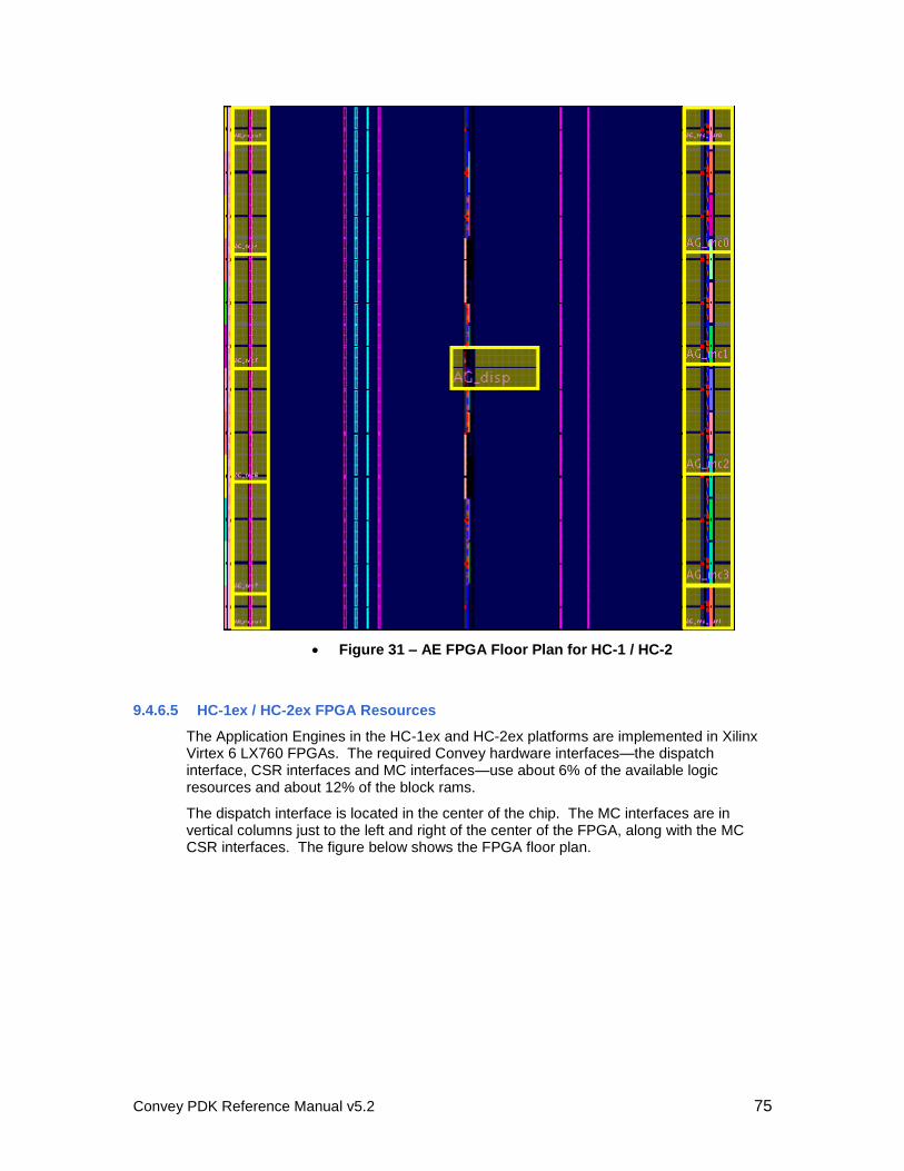
Convey PDK Reference Manual v5.2 75
Figure 31 – AE FPGA Floor Plan for HC-1 / HC-2
9.4.6.5 HC-1ex / HC-2ex FPGA Resources
The Application Engines in the HC-1ex and HC-2ex platforms are implemented in Xilinx Virtex 6 LX760 FPGAs. The required Convey hardware interfaces—the dispatch interface, CSR interfaces and MC interfaces—use about 6% of the available logic resources and about 12% of the block rams.
The dispatch interface is located in the center of the chip. The MC interfaces are in vertical columns just to the left and right of the center of the FPGA, along with the MC CSR interfaces. The figure below shows the FPGA floor plan.
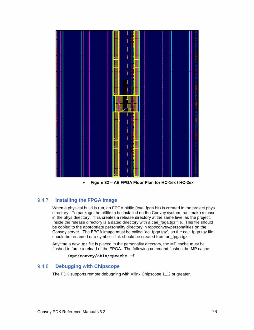
Convey PDK Reference Manual v5.2 76
Figure 32 – AE FPGA Floor Plan for HC-1ex / HC-2ex
9.4.7 Installing the FPGA Image
When a physical build is run, an FPGA bitfile (cae_fpga.bit) is created in the project phys directory. To package the bitfile to be installed on the Convey system, run ‘make release’ in the phys directory. This creates a release directory at the same level as the project. Inside the release directory is a dated directory with a cae_fpga.tgz file. This file should be copied to the appropriate personality directory in /opt/convey/personalities on the Convey server. The FPGA image must be called “ae_fpga.tgz”, so the cae_fpga.tgz file should be renamed or a symbolic link should be created from ae_fpga.tgz.
Anytime a new .tgz file is placed in the personality directory, the MP cache must be flushed to force a reload of the FPGA. The following command flushes the MP cache:
/opt/convey/sbin/mpcache –f
9.4.8 Debugging with Chipscope
The PDK supports remote debugging with Xilinx Chipscope 11.2 or greater.
Convey PDK Reference Manual v5.2 77
9.4.8.1 Inserting the Core
To insert a Chipscope core, run the Chipscope Core Inserter (inserter.sh or inserter for ISE 12+) from the <project>/phys directory with a routed netlist. Use “cae_fpga.ngc” for the input design netlist and “cae_fpga.ngo” for the output design netlist. When the core is inserted, typing “make” in the phys directory will reimplement the design from the ngdbuild step. The makefile will automatically insert a Chipscope core if the file “cae_fpga.cdc” exists..
9.4.8.2 Load the FPGA
When running Chipscope it is necessary to load the FPGA prior to running the analyzer. The following commands flush the cache, add the new image and load the image to be tested.
/opt/convey/sbin/mpcache –-flush
/opt/convey/sbin/mpcache –-add –S <personality>
/opt/convey/sbin/mpcache –-load –S <personality>
9.4.8.3 Running the Analyzer
Once the FPGA with Chipscope is installed on the Convey system, the Chipscope analyzer (analyzer.sh) can be run on the development system and can remotely connect to the Convey system. Follow the steps below to run the analyzer remotely:
1. On the Convey host server, start the remote Chipscope server:
/opt/convey/sbin/mpchipscope start
2. On the development system, run the Chipscope client (Chipscope version 11.2 or greater is required for remote connectivity).
analyzer.sh
click on the “JTAG Chain” menu and select “Open Plug-in”
In the Plug-in Parameters box, enter
‘xilinx_xvc host=[host IP]:2542
disableversioncheck=true’
3. A pop-up window displays 15 available FPGA devices. Click “OK” and wait for the analyzer to start.
4. Import the CDC file for one or more of the AE FPGAs (Devices 2, 3, 9 and 10):
AE0 DEV 10
AE1 DEV 9
AE2 DEV 2
AE3 DEV 3
Convey PDK Reference Manual v5.2 78
10 Setting up the Custom Personality
10.1.1 Personality Number and Nicknames
Each personality, including custom personalities, has a unique personality number, and one or more unique nicknames used to refer to that personality. Two ranges are reserved for custom personalities:
33000 – 64999 Worldwide personality numbers are assigned by Convey to anyone developing a custom personality that will someday be distributed to a wider customer base. ISV’s that develop a custom personality to accelerate their application should request a personality number from Convey. Send an e-mail to [email protected], and include a list of personality nicknames that you prefer.
Reserving personality numbers through Convey guarantees those personality numbers and nicknames will not collide with any other Convey provided or Convey assigned personality number. The user developed personality can be
easily bundled into a Linux RPM,
distributed via a website or CD/DVD,
installed on any compatible system the same way Convey’s personalities are installed, and
used by specifying any of the associated nicknames
65000 – 65535 Site (or company) local personality numbers are intended for personalities that will only be deployed within a company, and never released to external users. This range of personality numbers is managed by the site (or company), not by Convey.
10.1.1.1 Nickname Selection
Convey recommends that all site local and customer specified personality names include the providers name and/or package name as part of each nickname. For example, if company XYZ provided a personality for use with their software package named Fast Analysis Tool, a personality nickname such as xyz-fat would be easily recognizable, but unlikely to cause conflicts with other personality nicknames.
10.1.1.2 Reserved Signature Names
There are several reserved signature names, and variants thereof, which should not be overloaded by any user-defined signature. These reserved names are:
single, sp, The Convey provided single-precision vector personality. Convey expects to release variants of
Convey PDK Reference Manual v5.2 79
single_precision,
single_vector,
sp_vector
the single personality. These variants will have
similar names, such as single_fast or
single_fft.
double, dp,
double_precision,
double_vector,
dp_vector
The Convey provided double-precision vector personality. Convey expects to release variants of this personality also.
none The personality name none is reserved for
coprocessor routines that are personality neutral (only use the canonical instruction set). At runtime, any image loaded on the coprocessor can execute such a routine.
pdk The pdk personality is a sample personality delivered with the PDK package.
10.1.2 Defining the Personality for the Convey Simulator, Assembler, and Compilers
Convey provides several directories that provide a starting point for developing a new custom personality.
10.1.2.1 Sample Personality Description Directory
A sample custom personality directory is contained in
/opt/convey/personalities/4.1.1.1.0. This directory contains files that
describe the custom personality for the Convey compiler, assembler, and simulator. This sample custom personality directory should be copied to a new directory, named
x.1.1.1.0, where x is the personality number assigned to this new personality.
The command
cp –r /opt/convey/personalities/4.1.1.1.0 ~/32123.1.1.1.0
will copy the sample directory to the user’s home directory, creating a new directory named 32123.1.1.1.0.
Some of the files just copied into 32123.1.1.1.0/ need to be modified:
readme A brief description of the personality, used by the siglist
command
PersDesc.dat The personality description file, which lists the non-canonical instructions supported by this personality. Edit the personality description file and uncomment the lines for those custom instructions your personality will provide.
The remaining files (savecontext, restorecontext, and clearcontext) are
needed by the Convey coprocessor, and these routines are complete and ready to use with your new personality.
Convey PDK Reference Manual v5.2 80
If the personality directory is in a location other than /opt/convey/personalities, the CNY_PERSONALITY_PATH environment variable must be set to point to the directory just created, i.e.
export CNY_PERSONALITY_PATH=/home/my_dir/
or
setenv CNY_PERSONALITY_PATH /home/my_dir/
where /home/my_dir is your home directory or the directory 32123.1.1.1.0 was created
in.
After implementing the AE software model, copy the AE software model executable into the 32123.1.1.1.0/ directory with the file name caeemulator. This allows the model to be automatically executed when the personality is dispatched by an application. Alternatively, the CNY_CAE_EMULATOR can be used to define the full pathname of the AE software model executable.
In addition to the personality directory, the personality database must be created or updated with the new personality. The file /home/my_dir/customdb should contain a
line in the following format for each personality:
32123.1.1.1.0,myper
Convey PDK Reference Manual v5.2 81
11 Sample Custom Personality
This chapter describes the sample personality that can be used as a reference for new personality designs.
11.1 Overview
As part of the PDK package, Convey has developed a sample custom personality that can be used as a reference design. The sample personality was designed to be very simple while using all of the required hardware interfaces inside the FPGA. In addition the sample custom personality uses the read order cache and has the option to use the crossbar and the asynchronous interface.
Convey’s sample personality includes a memory-to-memory add instruction that adds values stored in one block of memory to the values stored in another block of memory. The array of results is stored back in memory. Details of the instructions and machine state registers are described below.
The sample personality contains 16 copies of a functional block, each of which adds a portion of the memory storing the operands. The functional blocks can directly connected to the memory controllers so that each block only performs operations on values in its attached memory or the optional crossbar may be used.
The sample personality can be used as a starting point for new PDK personalities. The sample personality can be found in each release of PDK in the following location:
/opt/convey/pdk/<rev>/<platform>/examples
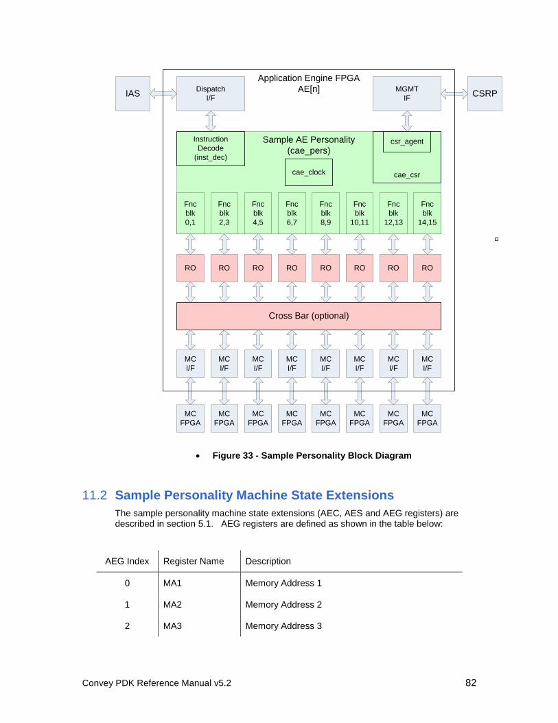
Convey PDK Reference Manual v5.2 82
IASDispatch
I/F
MGMT
IFCSRP
RO
MC
I/F
MC
I/F
MC
I/F
MC
I/F
MC
I/F
MC
I/F
MC
I/F
MC
I/F
RO RO RO RO RO RO RO
Sample AE Personality
(cae_pers)
Fnc
blk
0,1
Fnc
blk
2,3
Fnc
blk
4,5
Fnc
blk
6,7
Fnc
blk
8,9
Fnc
blk
10,11
Fnc
blk
12,13
Fnc
blk
14,15
MC
FPGA
MC
FPGA
MC
FPGA
MC
FPGA
MC
FPGA
MC
FPGA
MC
FPGA
MC
FPGA
Cross Bar (optional)
Instruction
Decode
(inst_dec)
cae_csr
csr_agent
cae_clock
Application Engine FPGA
AE[n]
Figure 33 - Sample Personality Block Diagram
11.2 Sample Personality Machine State Extensions
The sample personality machine state extensions (AEC, AES and AEG registers) are described in section 5.1. AEG registers are defined as shown in the table below:
AEG Index Register Name Description
0 MA1 Memory Address 1
1 MA2 Memory Address 2
2 MA3 Memory Address 3
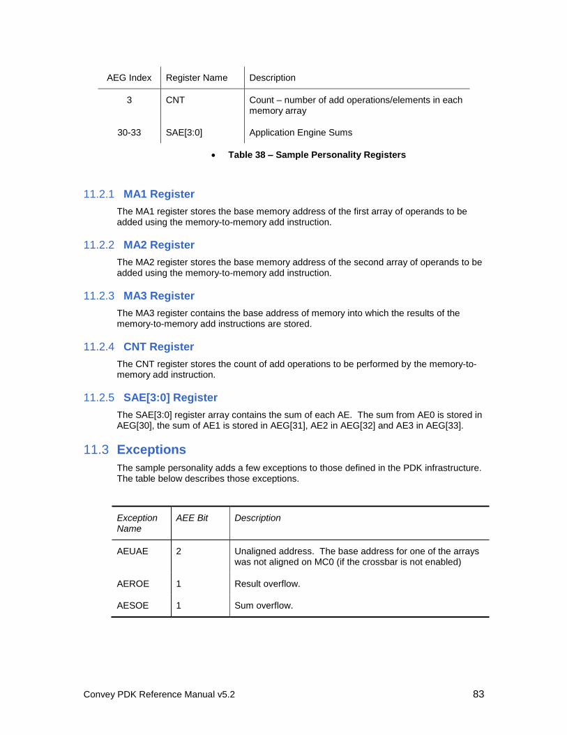
Convey PDK Reference Manual v5.2 83
AEG Index Register Name Description
3 CNT Count – number of add operations/elements in each memory array
30-33 SAE[3:0] Application Engine Sums
Table 38 – Sample Personality Registers
11.2.1 MA1 Register
The MA1 register stores the base memory address of the first array of operands to be added using the memory-to-memory add instruction.
11.2.2 MA2 Register
The MA2 register stores the base memory address of the second array of operands to be added using the memory-to-memory add instruction.
11.2.3 MA3 Register
The MA3 register contains the base address of memory into which the results of the memory-to-memory add instructions are stored.
11.2.4 CNT Register
The CNT register stores the count of add operations to be performed by the memory-to-memory add instruction.
11.2.5 SAE[3:0] Register
The SAE[3:0] register array contains the sum of each AE. The sum from AE0 is stored in AEG[30], the sum of AE1 is stored in AEG[31], AE2 in AEG[32] and AE3 in AEG[33].
11.3 Exceptions
The sample personality adds a few exceptions to those defined in the PDK infrastructure. The table below describes those exceptions.
Exception Name
AEE Bit Description
AEUAE 2 Unaligned address. The base address for one of the arrays was not aligned on MC0 (if the crossbar is not enabled)
AEROE 1 Result overflow.
AESOE 1 Sum overflow.
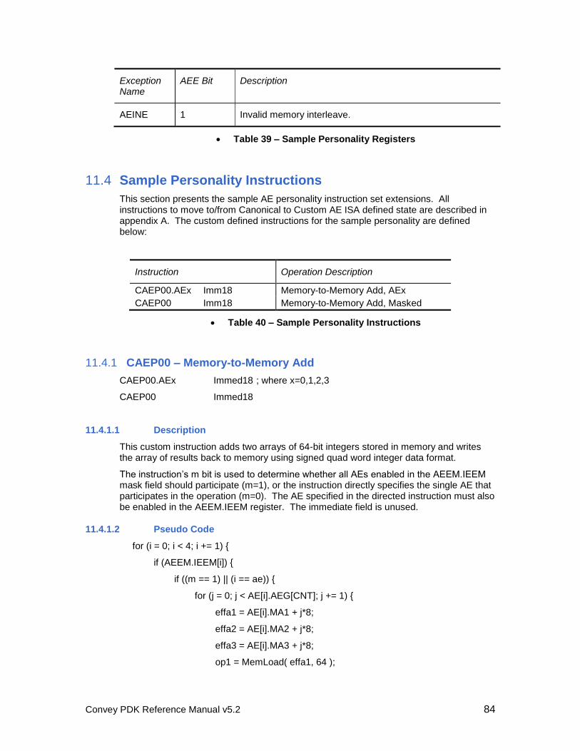
Convey PDK Reference Manual v5.2 84
Exception Name
AEE Bit Description
AEINE 1 Invalid memory interleave.
Table 39 – Sample Personality Registers
11.4 Sample Personality Instructions
This section presents the sample AE personality instruction set extensions. All instructions to move to/from Canonical to Custom AE ISA defined state are described in appendix A. The custom defined instructions for the sample personality are defined below:
Instruction Operation Description
CAEP00.AEx Imm18 Memory-to-Memory Add, AEx
CAEP00 Imm18 Memory-to-Memory Add, Masked
Table 40 – Sample Personality Instructions
11.4.1 CAEP00 – Memory-to-Memory Add
CAEP00.AEx Immed18 ; where x=0,1,2,3
CAEP00 Immed18
11.4.1.1 Description
This custom instruction adds two arrays of 64-bit integers stored in memory and writes the array of results back to memory using signed quad word integer data format.
The instruction’s m bit is used to determine whether all AEs enabled in the AEEM.IEEM mask field should participate (m=1), or the instruction directly specifies the single AE that participates in the operation (m=0). The AE specified in the directed instruction must also be enabled in the AEEM.IEEM register. The immediate field is unused.
11.4.1.2 Pseudo Code
for (i = 0; i < 4; i += 1) {
if (AEEM.IEEM[i]) {
if ((m == 1) || (i == ae)) {
for (j = 0; j < AE[i].AEG[CNT]; j += 1) {
effa1 = AE[i].MA1 + j*8;
effa2 = AE[i].MA2 + j*8;
effa3 = AE[i].MA3 + j*8;
op1 = MemLoad( effa1, 64 );
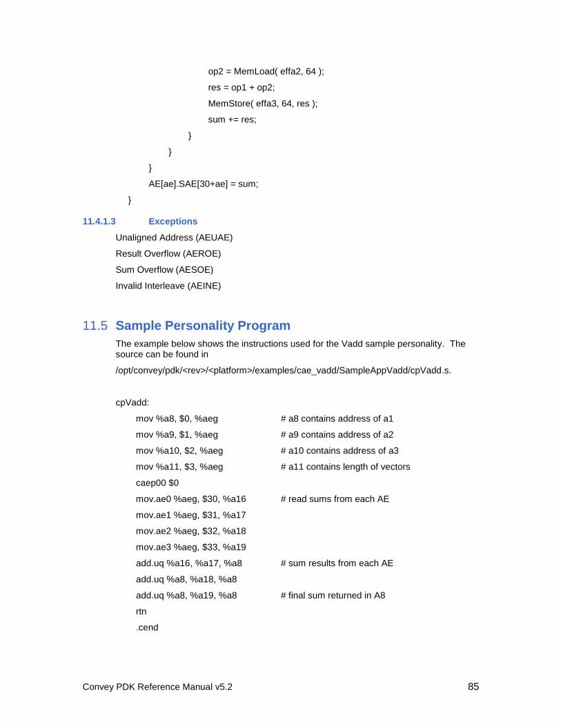
Convey PDK Reference Manual v5.2 85
op2 = MemLoad( effa2, 64 );
res = op1 + op2;
MemStore( effa3, 64, res );
sum += res;
}
}
}
AE[ae].SAE[30+ae] = sum;
}
11.4.1.3 Exceptions
Unaligned Address (AEUAE)
Result Overflow (AEROE)
Sum Overflow (AESOE)
Invalid Interleave (AEINE)
11.5 Sample Personality Program
The example below shows the instructions used for the Vadd sample personality. The source can be found in
/opt/convey/pdk/<rev>/<platform>/examples/cae_vadd/SampleAppVadd/cpVadd.s.
cpVadd:
mov %a8, $0, %aeg # a8 contains address of a1
mov %a9, $1, %aeg # a9 contains address of a2
mov %a10, $2, %aeg # a10 contains address of a3
mov %a11, $3, %aeg # a11 contains length of vectors
caep00 $0
mov.ae0 %aeg, $30, %a16 # read sums from each AE
mov.ae1 %aeg, $31, %a17
mov.ae2 %aeg, $32, %a18
mov.ae3 %aeg, $33, %a19
add.uq %a16, %a17, %a8 # sum results from each AE
add.uq %a8, %a18, %a8
add.uq %a8, %a19, %a8 # final sum returned in A8
rtn
.cend
Convey PDK Reference Manual v5.2 86
11.6 Running the Sample Application
11.6.1 Copy Sample AE and Sample Application
The vector add sample personality and application are installed with the PDK RPM in /opt/convey/pdk/<rev>/<platform>/examples/cae_vadd. The project should be copied to a working directory such as the user’s home directory.
11.6.2 Build the Sample AE and Sample Application
Everything needed to run the sample application, including the application itself and the software model of the sample personality, is in the PDK RPM package (note that gcc and g++ are prerequisites for Convey compilers).
To build the user application, type `make` in the SampleAppVadd directory. This
generates an executable called UserApp.exe that can be run in simulation or on the hardware.
11.6.3 Run the Application
Scripts in the SampleAppVadd directory allow the user to run the application in simulation or on the hardware:
./run # runs the simulation using the software model
./run –vsim # runs the hardware simulation
./runcp # runs the sample application on the hardware
These scripts set the appropriate environment variables, including the following:
# run the application using the simulator
CNY_SIM_THREAD = libcpSimLib2.so
# select the software model of the AE for simulation
CNY_CAE_EMULATOR = ../sim/CaeSimPers
Convey-specific environment variables are defined in the Convey Programmers Guide.

Convey PDK Reference Manual v5.2 87
A PDK Instructions
The following pages describe PDK instruction set. Note that only AE instructions available to PDK personalities are listed here. Scalar instructions are defined in the Convey Reference Manual.
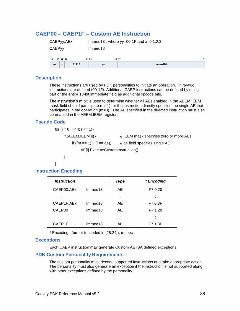
Convey PDK Reference Manual v5.2 88
CAEP00 – CAEP1F – Custom AE Instruction
CAEPyy.AEx Immed18 ; where yy=00-1F and x=0,1,2,3
CAEPyy Immed18
11110
28 24
Immed18
0
opc
23 18 1731 30 29
ae m
Description
These instructions are used by PDK personalities to initiate an operation. Thirty-two instructions are defined (00-1F). Additional CAEP instructions can be defined by using part or the entire 18-bit immediate field as additional opcode bits.
The instruction’s m bit is used to determine whether all AEs enabled in the AEEM.IEEM mask field should participate (m=1), or the instruction directly specifies the single AE that participates in the operation (m=0). The AE specified in the directed instruction must also be enabled in the AEEM.IEEM register.
Pseudo Code
for (i = 0; i < 4; i += 1) {
if (AEEM.IEEM[i]) { // IEEM mask specifies zero or more AEs
if ((m == 1) || (i == ae)) // ae field specifies single AE
AE[i].ExecuteCustomInstruction();
}
}
Instruction Encoding
Instruction Type * Encoding
CAEP00.AEx Immed18 AE F7,0,20
: : :
CAEP1F.AEx Immed18 AE F7,0,3F
CAEP00 Immed18 AE F7,1,20
: : :
CAEP1F Immed18 AE F7,1,3F
* Encoding: format (encoded in [28:24]), m, opc
Exceptions
Each CAEP instruction may generate Custom AE ISA defined exceptions.
PDK Custom Personality Requirements
The custom personality must decode supported instructions and take appropriate action. The personality must also generate an exception if the instruction is not supported along with other exceptions defined by the personality.
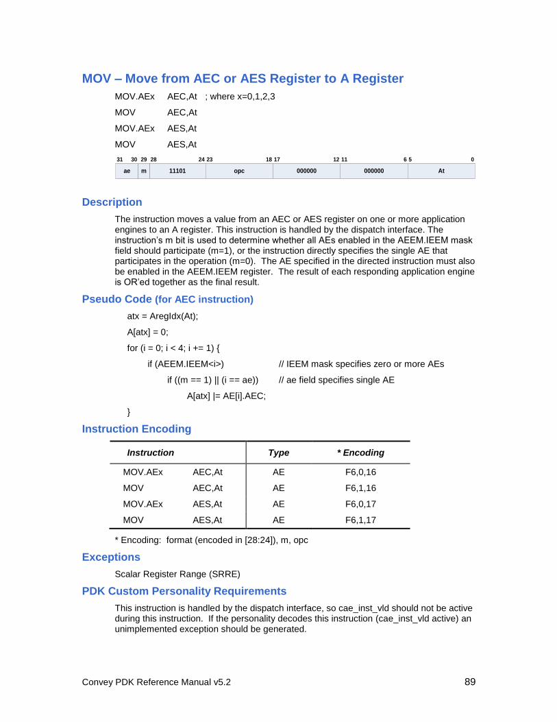
Convey PDK Reference Manual v5.2 89
MOV – Move from AEC or AES Register to A Register
MOV.AEx AEC,At ; where x=0,1,2,3
MOV AEC,At
MOV.AEx AES,At
MOV AES,At
11101
28 24
000000
11 6
At
5 0
opc
23
000000
1218 1731 30 29
ae m
Description
The instruction moves a value from an AEC or AES register on one or more application engines to an A register. This instruction is handled by the dispatch interface. The instruction’s m bit is used to determine whether all AEs enabled in the AEEM.IEEM mask field should participate (m=1), or the instruction directly specifies the single AE that participates in the operation (m=0). The AE specified in the directed instruction must also be enabled in the AEEM.IEEM register. The result of each responding application engine is OR’ed together as the final result.
Pseudo Code (for AEC instruction)
atx = AregIdx(At);
A[atx] = 0;
for (i = 0; i < 4; i += 1) {
if (AEEM.IEEM<i>) // IEEM mask specifies zero or more AEs
if ((m == 1) || (i == ae)) // ae field specifies single AE
A[atx] |= AE[i].AEC;
}
Instruction Encoding
Instruction Type * Encoding
MOV.AEx AEC,At AE F6,0,16
MOV AEC,At AE F6,1,16
MOV.AEx AES,At AE F6,0,17
MOV AES,At AE F6,1,17
* Encoding: format (encoded in [28:24]), m, opc
Exceptions
Scalar Register Range (SRRE)
PDK Custom Personality Requirements
This instruction is handled by the dispatch interface, so cae_inst_vld should not be active during this instruction. If the personality decodes this instruction (cae_inst_vld active) an unimplemented exception should be generated.
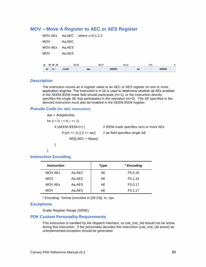
Convey PDK Reference Manual v5.2 90
MOV – Move A Register to AEC or AES Register
MOV.AEx Aa,AEC ; where x=0,1,2,3
MOV Aa,AEC
MOV.AEx Aa,AES
MOV Aa,AES
11100
28 24
Aa
11 6
000000
5 0
opc
23
000000
1218 1731 30 29
ae m
Description
The instruction moves an A register value to an AEC or AES register on one or more application engines. The instruction’s m bit is used to determine whether all AEs enabled in the AEEM.IEEM mask field should participate (m=1), or the instruction directly specifies the single AE that participates in the operation (m=0). The AE specified in the directed instruction must also be enabled in the AEEM.IEEM register.
Pseudo Code (for AEC instruction)
aax = AregIdx(Aa);
for (i = 0; i < 4; i += 1)
if (AEEM.IEEM<i>) { // IEEM mask specifies zero or more AEs
if ((m == 1) || (i == ae)) // ae field specifies single AE
AE[i].AEC = A[aax];
}
}
Instruction Encoding
Instruction Type * Encoding
MOV.AEx Aa,AEC AE F5,0,16
MOV Aa,AEC AE F5,1,16
MOV.AEx Aa,AES AE F5,0,17
MOV Aa,AES AE F5,1,17
* Encoding: format (encoded in [28:24]), m, opc
Exceptions
Scalar Register Range (SRRE)
PDK Custom Personality Requirements
This instruction is handled by the dispatch interface, so cae_inst_vld should not be active during this instruction. If the personality decodes this instruction (cae_inst_vld active) an unimplemented exception should be generated.
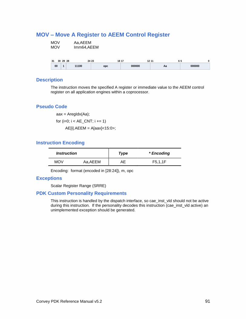
Convey PDK Reference Manual v5.2 91
MOV – Move A Register to AEEM Control Register
MOV Aa,AEEM MOV Imm64,AEEM
11100
28 24
Aa
11 6
000000
5 0
opc
23
000000
1218 1731 30 29
00 1
Description
The instruction moves the specified A register or immediate value to the AEEM control register on all application engines within a coprocessor.
Pseudo Code
aax = AregIdx(Aa);
for (i=0; i < AE_CNT; i += 1)
AE[i].AEEM = A[aax]<15:0>;
Instruction Encoding
Instruction Type * Encoding
MOV Aa,AEEM AE F5,1,1F
Encoding: format (encoded in [28:24]), m, opc
Exceptions
Scalar Register Range (SRRE)
PDK Custom Personality Requirements
This instruction is handled by the dispatch interface, so cae_inst_vld should not be active during this instruction. If the personality decodes this instruction (cae_inst_vld active) an unimplemented exception should be generated.
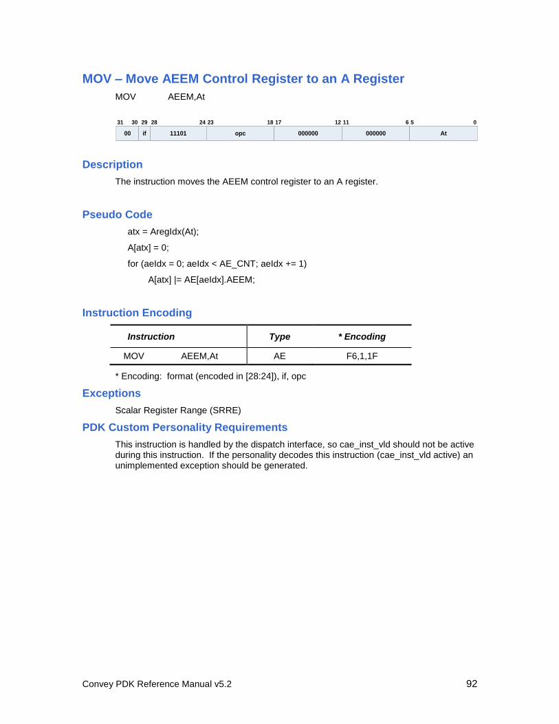
Convey PDK Reference Manual v5.2 92
MOV – Move AEEM Control Register to an A Register
MOV AEEM,At
11101
28 24
000000
11 6
At
5 0
opc
23
000000
1218 1731 30 29
00 if
Description
The instruction moves the AEEM control register to an A register.
Pseudo Code
atx = AregIdx(At);
A[atx] = 0;
for (aeIdx = 0; aeIdx < AE_CNT; aeIdx += 1)
A[atx] |= AE[aeIdx].AEEM;
Instruction Encoding
Instruction Type * Encoding
MOV AEEM,At AE F6,1,1F
* Encoding: format (encoded in [28:24]), if, opc
Exceptions
Scalar Register Range (SRRE)
PDK Custom Personality Requirements
This instruction is handled by the dispatch interface, so cae_inst_vld should not be active during this instruction. If the personality decodes this instruction (cae_inst_vld active) an unimplemented exception should be generated.
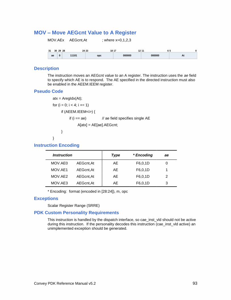
Convey PDK Reference Manual v5.2 93
MOV – Move AEGcnt Value to A Register
MOV.AEx AEGcnt,At ; where x=0,1,2,3
11101
28 24
000000
11 6
At
5 0
opc
23
000000
1218 1731 30 29
ae 0
Description
The instruction moves an AEGcnt value to an A register. The instruction uses the ae field to specify which AE is to respond. The AE specified in the directed instruction must also be enabled in the AEEM.IEEM register.
Pseudo Code
atx = AregIdx(At);
for (i = 0; i < 4; i += 1)
if (AEEM.IEEM<i>) {
if (i == ae) // ae field specifies single AE
A[atx] = AE[ae].AEGcnt;
}
}
Instruction Encoding
Instruction Type * Encoding ae
MOV.AE0 AEGcnt,At AE F6,0,1D 0
MOV.AE1 AEGcnt,At AE F6,0,1D 1
MOV.AE2 AEGcnt,At AE F6,0,1D 2
MOV.AE3 AEGcnt,At AE F6,0,1D 3
* Encoding: format (encoded in [28:24]), m, opc
Exceptions
Scalar Register Range (SRRE)
PDK Custom Personality Requirements
This instruction is handled by the dispatch interface, so cae_inst_vld should not be active during this instruction. If the personality decodes this instruction (cae_inst_vld active) an unimplemented exception should be generated.
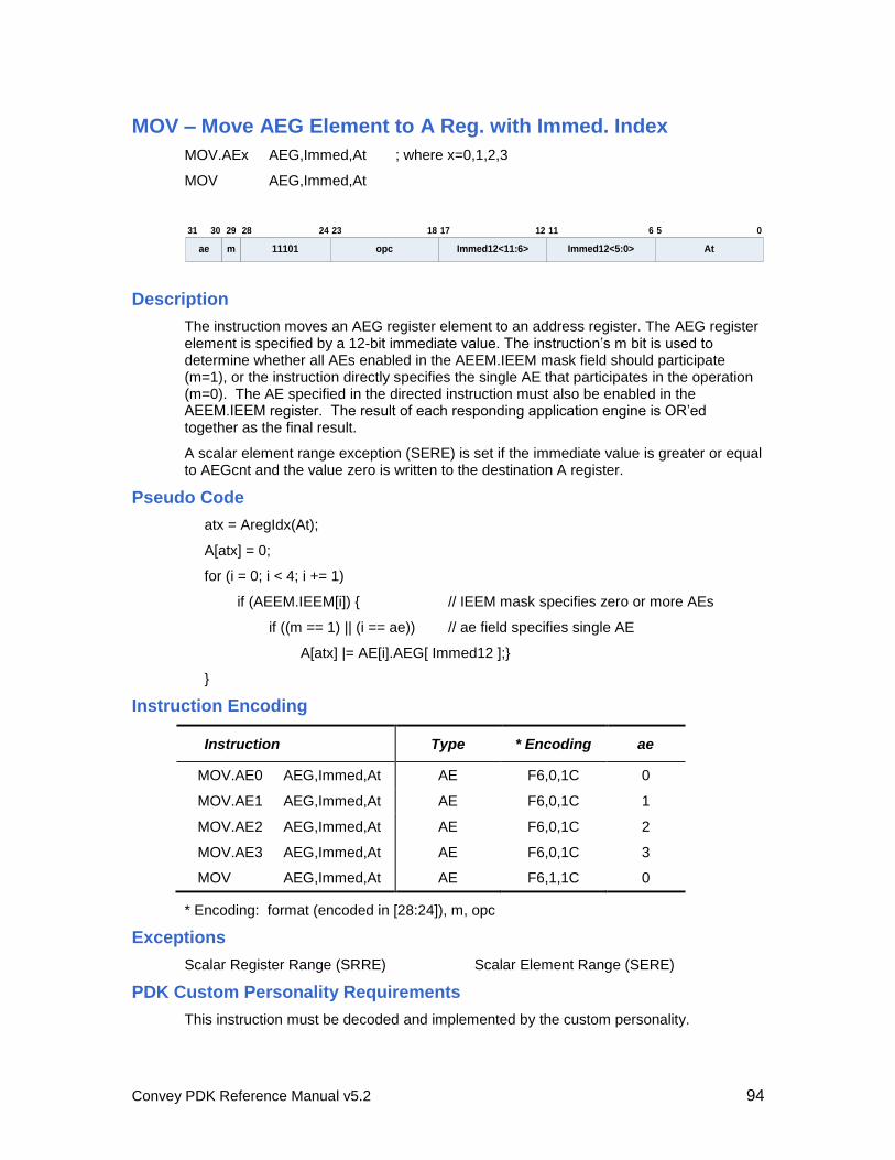
Convey PDK Reference Manual v5.2 94
MOV – Move AEG Element to A Reg. with Immed. Index
MOV.AEx AEG,Immed,At ; where x=0,1,2,3
MOV AEG,Immed,At
11101
28 24
Immed12<5:0>
11 6
At
5 0
opc
23
Immed12<11:6>
1218 1731 30 29
ae m
Description
The instruction moves an AEG register element to an address register. The AEG register element is specified by a 12-bit immediate value. The instruction’s m bit is used to determine whether all AEs enabled in the AEEM.IEEM mask field should participate (m=1), or the instruction directly specifies the single AE that participates in the operation (m=0). The AE specified in the directed instruction must also be enabled in the AEEM.IEEM register. The result of each responding application engine is OR’ed together as the final result.
A scalar element range exception (SERE) is set if the immediate value is greater or equal to AEGcnt and the value zero is written to the destination A register.
Pseudo Code
atx = AregIdx(At);
A[atx] = 0;
for (i = 0; i < 4; i += 1)
if (AEEM.IEEM[i]) { // IEEM mask specifies zero or more AEs
if ((m == 1) || (i == ae)) // ae field specifies single AE
A[atx] |= AE[i].AEG[ Immed12 ];}
}
Instruction Encoding
Instruction Type * Encoding ae
MOV.AE0 AEG,Immed,At AE F6,0,1C 0
MOV.AE1 AEG,Immed,At AE F6,0,1C 1
MOV.AE2 AEG,Immed,At AE F6,0,1C 2
MOV.AE3 AEG,Immed,At AE F6,0,1C 3
MOV AEG,Immed,At AE F6,1,1C 0
* Encoding: format (encoded in [28:24]), m, opc
Exceptions
Scalar Register Range (SRRE) Scalar Element Range (SERE)
PDK Custom Personality Requirements
This instruction must be decoded and implemented by the custom personality.
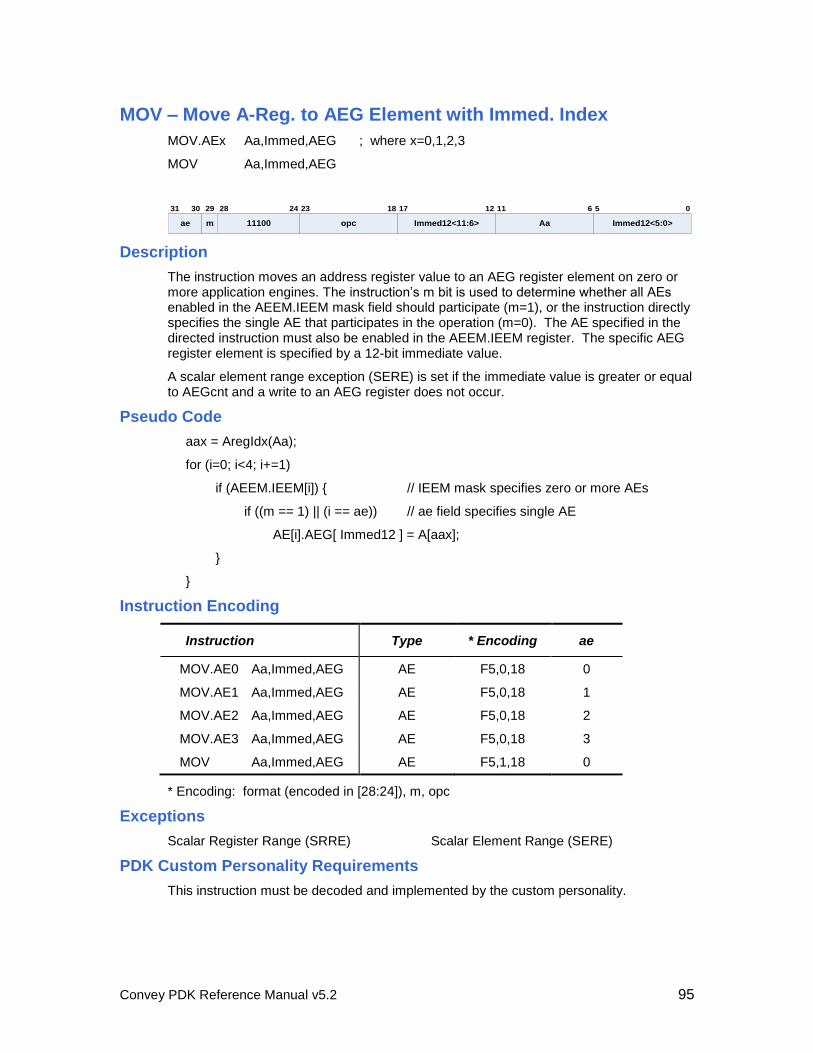
Convey PDK Reference Manual v5.2 95
MOV – Move A-Reg. to AEG Element with Immed. Index
MOV.AEx Aa,Immed,AEG ; where x=0,1,2,3
MOV Aa,Immed,AEG
11100
28 24
Aa
11 6
Immed12<5:0>
5 0
opc
23
Immed12<11:6>
1218 1731 30 29
ae m
Description
The instruction moves an address register value to an AEG register element on zero or more application engines. The instruction’s m bit is used to determine whether all AEs enabled in the AEEM.IEEM mask field should participate (m=1), or the instruction directly specifies the single AE that participates in the operation (m=0). The AE specified in the directed instruction must also be enabled in the AEEM.IEEM register. The specific AEG register element is specified by a 12-bit immediate value.
A scalar element range exception (SERE) is set if the immediate value is greater or equal to AEGcnt and a write to an AEG register does not occur.
Pseudo Code
aax = AregIdx(Aa);
for (i=0; i<4; i+=1)
if (AEEM.IEEM[i]) { // IEEM mask specifies zero or more AEs
if ((m == 1) || (i == ae)) // ae field specifies single AE
AE[i].AEG[ Immed12 ] = A[aax];
}
}
Instruction Encoding
Instruction Type * Encoding ae
MOV.AE0 Aa,Immed,AEG AE F5,0,18 0
MOV.AE1 Aa,Immed,AEG AE F5,0,18 1
MOV.AE2 Aa,Immed,AEG AE F5,0,18 2
MOV.AE3 Aa,Immed,AEG AE F5,0,18 3
MOV Aa,Immed,AEG AE F5,1,18 0
* Encoding: format (encoded in [28:24]), m, opc
Exceptions
Scalar Register Range (SRRE) Scalar Element Range (SERE)
PDK Custom Personality Requirements
This instruction must be decoded and implemented by the custom personality.
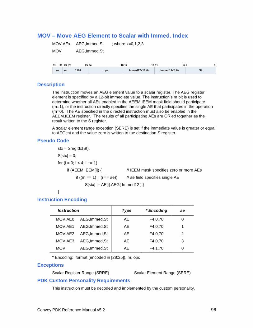
Convey PDK Reference Manual v5.2 96
MOV – Move AEG Element to Scalar with Immed. Index
MOV.AEx AEG,Immed,St ; where x=0,1,2,3
MOV AEG,Immed,St
Immed12<5:0>
11 6
St
5 0
Immed12<11:6>
121731 30 29
ae m 1101
28 25
opc
24 18
Description
The instruction moves an AEG element value to a scalar register. The AEG register element is specified by a 12-bit immediate value. The instruction’s m bit is used to determine whether all AEs enabled in the AEEM.IEEM mask field should participate (m=1), or the instruction directly specifies the single AE that participates in the operation (m=0). The AE specified in the directed instruction must also be enabled in the AEEM.IEEM register. The results of all participating AEs are OR’ed together as the result written to the S register.
A scalar element range exception (SERE) is set if the immediate value is greater or equal to AEGcnt and the value zero is written to the destination S register.
Pseudo Code
stx = SregIdx(St);
S[stx] = 0;
for (i = 0; i < 4; i += 1)
if (AEEM.IEEM[i]) { // IEEM mask specifies zero or more AEs
if ((m == 1) || (i == ae)) // ae field specifies single AE
S[stx] |= AE[i].AEG[ Immed12 ];}
}
Instruction Encoding
Instruction Type * Encoding ae
MOV.AE0 AEG,Immed,St AE F4,0,70 0
MOV.AE1 AEG,Immed,St AE F4,0,70 1
MOV.AE2 AEG,Immed,St AE F4,0,70 2
MOV.AE3 AEG,Immed,St AE F4,0,70 3
MOV AEG,Immed,St AE F4,1,70 0
* Encoding: format (encoded in [28:25]), m, opc
Exceptions
Scalar Register Range (SRRE) Scalar Element Range (SERE)
PDK Custom Personality Requirements
This instruction must be decoded and implemented by the custom personality.
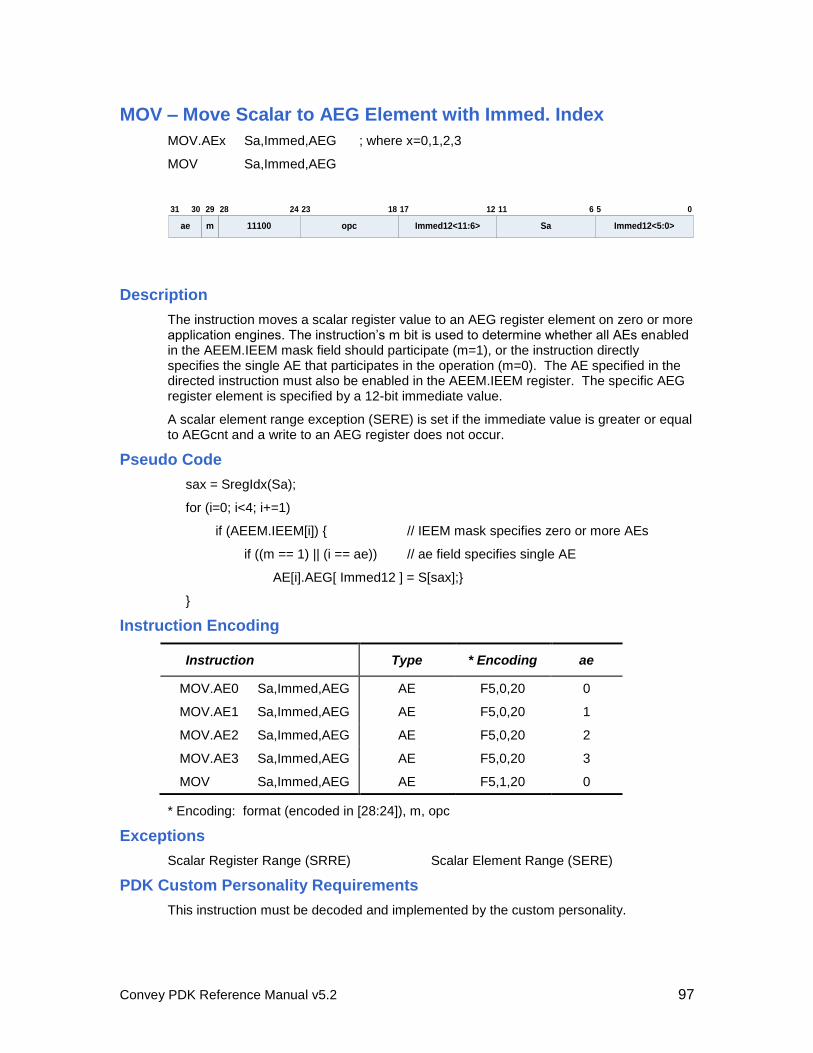
Convey PDK Reference Manual v5.2 97
MOV – Move Scalar to AEG Element with Immed. Index
MOV.AEx Sa,Immed,AEG ; where x=0,1,2,3
MOV Sa,Immed,AEG
11100
28 24
Sa
11 6
Immed12<5:0>
5 0
opc
23
Immed12<11:6>
1218 1731 30 29
ae m
Description
The instruction moves a scalar register value to an AEG register element on zero or more application engines. The instruction’s m bit is used to determine whether all AEs enabled in the AEEM.IEEM mask field should participate (m=1), or the instruction directly specifies the single AE that participates in the operation (m=0). The AE specified in the directed instruction must also be enabled in the AEEM.IEEM register. The specific AEG register element is specified by a 12-bit immediate value.
A scalar element range exception (SERE) is set if the immediate value is greater or equal to AEGcnt and a write to an AEG register does not occur.
Pseudo Code
sax = SregIdx(Sa);
for (i=0; i<4; i+=1)
if (AEEM.IEEM[i]) { // IEEM mask specifies zero or more AEs
if ((m == 1) || (i == ae)) // ae field specifies single AE
AE[i].AEG[ Immed12 ] = S[sax];}
}
Instruction Encoding
Instruction Type * Encoding ae
MOV.AE0 Sa,Immed,AEG AE F5,0,20 0
MOV.AE1 Sa,Immed,AEG AE F5,0,20 1
MOV.AE2 Sa,Immed,AEG AE F5,0,20 2
MOV.AE3 Sa,Immed,AEG AE F5,0,20 3
MOV Sa,Immed,AEG AE F5,1,20 0
* Encoding: format (encoded in [28:24]), m, opc
Exceptions
Scalar Register Range (SRRE) Scalar Element Range (SERE)
PDK Custom Personality Requirements
This instruction must be decoded and implemented by the custom personality.
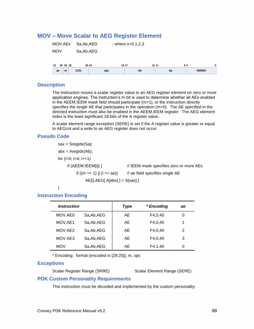
Convey PDK Reference Manual v5.2 98
MOV – Move Scalar to AEG Register Element
MOV.AEx Sa,Ab,AEG ; where x=0,1,2,3
MOV Sa,Ab,AEG
Sa
11 6
000000
5 0
Ab
121731 30 29
ae m 1101
28 25
opc
24 18
Description
The instruction moves a scalar register value to an AEG register element on zero or more application engines. The instruction’s m bit is used to determine whether all AEs enabled in the AEEM.IEEM mask field should participate (m=1), or the instruction directly specifies the single AE that participates in the operation (m=0). The AE specified in the directed instruction must also be enabled in the AEEM.IEEM register. The AEG element index is the least significant 18-bits of the A register value.
A scalar element range exception (SERE) is set if the A register value is greater or equal to AEGcnt and a write to an AEG register does not occur.
Pseudo Code
sax = SregIdx(Sa);
abx = AregIdx(Ab);
for (i=0; i<4; i+=1)
if (AEEM.IEEM[i]) { // IEEM mask specifies zero or more AEs
if ((m == 1) || (i == ae)) // ae field specifies single AE
AE[i].AEG[ A[abx] ] = S[sax];}
}
Instruction Encoding
Instruction Type * Encoding ae
MOV.AE0 Sa,Ab,AEG AE F4,0,40 0
MOV.AE1 Sa,Ab,AEG AE F4,0,40 1
MOV.AE2 Sa,Ab,AEG AE F4,0,40 2
MOV.AE3 Sa,Ab,AEG AE F4,0,40 3
MOV Sa,Ab,AEG AE F4,1,40 0
* Encoding: format (encoded in [28:25]), m, opc
Exceptions
Scalar Register Range (SRRE) Scalar Element Range (SERE)
PDK Custom Personality Requirements
This instruction must be decoded and implemented by the custom personality.
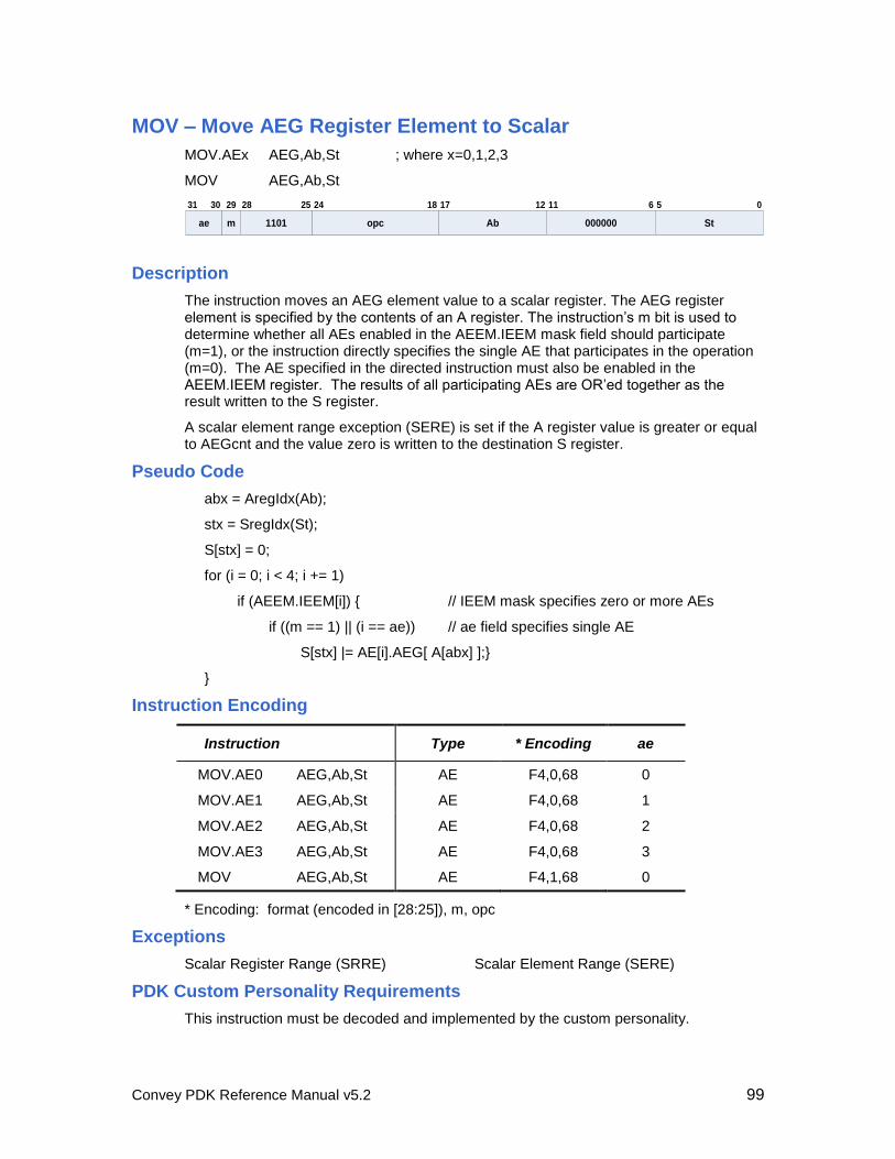
Convey PDK Reference Manual v5.2 99
MOV – Move AEG Register Element to Scalar
MOV.AEx AEG,Ab,St ; where x=0,1,2,3
MOV AEG,Ab,St
000000
11 6
St
5 0
Ab
121731 30 29
ae m 1101
28 25
opc
24 18
Description
The instruction moves an AEG element value to a scalar register. The AEG register element is specified by the contents of an A register. The instruction’s m bit is used to determine whether all AEs enabled in the AEEM.IEEM mask field should participate (m=1), or the instruction directly specifies the single AE that participates in the operation (m=0). The AE specified in the directed instruction must also be enabled in the AEEM.IEEM register. The results of all participating AEs are OR’ed together as the result written to the S register.
A scalar element range exception (SERE) is set if the A register value is greater or equal to AEGcnt and the value zero is written to the destination S register.
Pseudo Code
abx = AregIdx(Ab);
stx = SregIdx(St);
S[stx] = 0;
for (i = 0; i < 4; i += 1)
if (AEEM.IEEM[i]) { // IEEM mask specifies zero or more AEs
if ((m == 1) || (i == ae)) // ae field specifies single AE
S[stx] |= AE[i].AEG[ A[abx] ];}
}
Instruction Encoding
Instruction Type * Encoding ae
MOV.AE0 AEG,Ab,St AE F4,0,68 0
MOV.AE1 AEG,Ab,St AE F4,0,68 1
MOV.AE2 AEG,Ab,St AE F4,0,68 2
MOV.AE3 AEG,Ab,St AE F4,0,68 3
MOV AEG,Ab,St AE F4,1,68 0
* Encoding: format (encoded in [28:25]), m, opc
Exceptions
Scalar Register Range (SRRE) Scalar Element Range (SERE)
PDK Custom Personality Requirements
This instruction must be decoded and implemented by the custom personality.
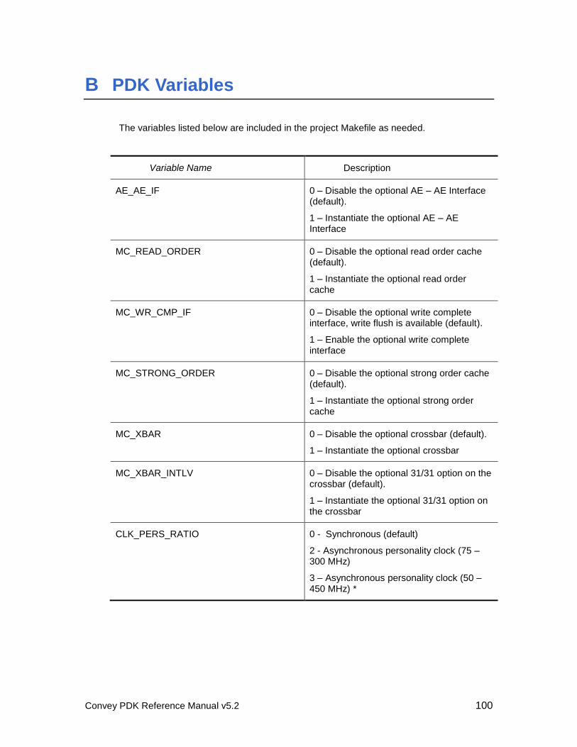
Convey PDK Reference Manual v5.2 100
B PDK Variables
The variables listed below are included in the project Makefile as needed.
Variable Name Description
AE_AE_IF 0 – Disable the optional AE – AE Interface (default).
1 – Instantiate the optional AE – AE Interface
MC_READ_ORDER 0 – Disable the optional read order cache (default).
1 – Instantiate the optional read order cache
MC_WR_CMP_IF 0 – Disable the optional write complete interface, write flush is available (default).
1 – Enable the optional write complete interface
MC_STRONG_ORDER 0 – Disable the optional strong order cache (default).
1 – Instantiate the optional strong order cache
MC_XBAR 0 – Disable the optional crossbar (default).
1 – Instantiate the optional crossbar
MC_XBAR_INTLV 0 – Disable the optional 31/31 option on the crossbar (default).
1 – Instantiate the optional 31/31 option on the crossbar
CLK_PERS_RATIO 0 - Synchronous (default)
2 - Asynchronous personality clock (75 – 300 MHz)
3 – Asynchronous personality clock (50 – 450 MHz) *
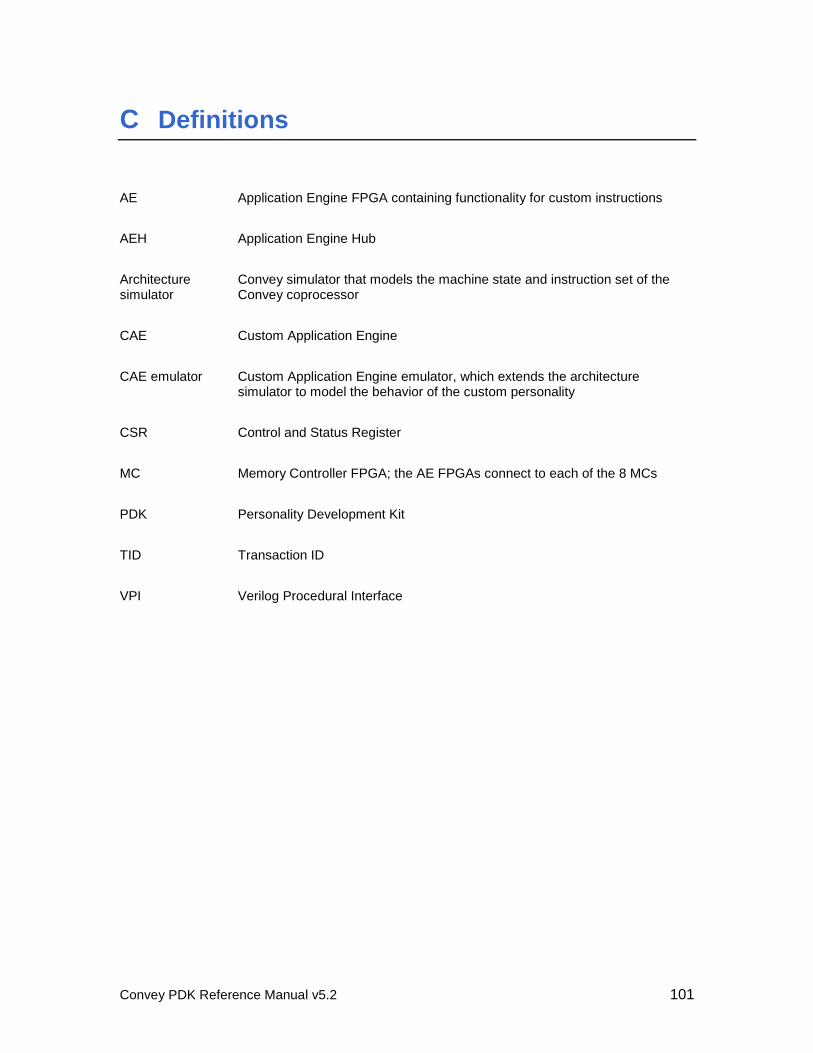
Convey PDK Reference Manual v5.2 101
C Definitions
AE Application Engine FPGA containing functionality for custom instructions
AEH Application Engine Hub
Architecture simulator
Convey simulator that models the machine state and instruction set of the Convey coprocessor
CAE Custom Application Engine
CAE emulator Custom Application Engine emulator, which extends the architecture simulator to model the behavior of the custom personality
CSR Control and Status Register
MC Memory Controller FPGA; the AE FPGAs connect to each of the 8 MCs
PDK Personality Development Kit
TID Transaction ID
VPI Verilog Procedural Interface
Convey PDK Reference Manual v5.2 102
D Packaging the Custom Personality
Packaging Overview
Convey’s PDK sample personality includes the necessary files and scripts to package a user developed custom personality. The resulting rpm package is suitable for installation on a Convey Adaptive Application Server, as well as any x86-64 Linux system that has the standard rpm tools installed. Support for creating Debian (Ubuntu) packages is described at the end of this section.
A personality package consists of:
an AE software model that provides software emulation of the custom instructions provided by a custom personality (via a socket based interface with the Convey simulator)
a custom FPGA image (for the Application Engine) that implements the custom instructions on the Convey coprocessor
a personality description file for use by Convey’s compilers and assembler (it describes which custom instructions are provided by the personality)
context save/restore/zero routines (provided by Convey, suitable for use with any custom personality)
a readme file that describes the personality (provided to the end user of the personality)
Either the AE software model or the custom FPGA image is required in order for the packaged personality to be useful. The AE software model allows application development and testing using the custom instruction emulation provided by the AE software model, while the custom FPGA image allows the Convey coprocessor to be used to execute the custom instructions.
Other sections of this document describe how to create the AE software model, the custom FPGA image, and the personality description file for a custom personality.
The convey-pdk_per package, one of the packages provided by Convey, provides a sample custom personality, and the packaging scripts and other files required to package a custom personality. These other files include a sample readme file that should be customized for your custom personality. See the Convey System Administration Guide for information on installing Convey supplied packages.
Packaging Requirements
A Convey Hybrid-Core server is an ideal system for packaging your custom personality, and has all the necessary tools installed. If you choose to package a custom personality on a different system, that system should:
be running a 64bit Linux O.S,
have the rpmbuild tool installed, and
have Convey’s convey-pdk_per package installed.
Convey PDK Reference Manual v5.2 103
Convey has tested the packaging scripts on Redhat EL 5, and openSUSE 11.0. Other distributions are likely to work, but differences in default rpm macro definitions may cause problems.
A Debian package can be created from the rpm package, using the 3rd
party alien tool, described later in this section.
If the Linux distribution you are using does not support the rpm package format, you might consider booting up one of the ‘live’ Linux distributions that does support the rpm package creation tools, and creating the rpm packages there. Alternatively, you can use the packaging tools supported by your Linux distribution to create a different package format (presumably a Debian package). One last alternative is to distribute the appropriate files as a tar bundle, with instructions on how to install the files in the /opt/convey/personalities directory. In any case, the installation needs to mimic the /opt/convey/personalities/nnn.1.1.1.0 directory structure described immediately below, and contain the same files therein. The Convey supplied packaging script also ensures that when the created package is installed, the /opt/convey/sbin/updateCustomDB script is called with the appropriate arguments to update the custom personality database in /opt/convey/personalities/customdb.
Step by Step Packaging Instructions
These instructions assume the AE software model and the custom FPGA image have already been created, and are ready to be packaged. If you only want to deliver one of these items, leave the corresponding Convey provided placeholder in the appropriate directory.
Create a directory to build the rpm package in mkdir mypackage
cd mypackage
Copy the Convey provided sample packaging
cp -r /opt/convey/pdk/pdkPackaging/* . ls
BUILD/ createrpm* Readme root/ RPMS/ SPECS/
Rename the sample personality directory cd root/opt/convey/personalities
mv MYPER.1.1.1.0 nnn.1.1.1.0
where nnn is the appropriate personality number, chosen from the site local personality number range, or a global unique number assigned to you by Convey
cd nnn.1.1.1.0 ls
ae_fpga.bit caeemulator PersDesc.dat readme rest.o save.o
zero.o
edit ‘readme’, replacing “MY CUSTOM PERSONALITY” with the name of your personality, replacing “MYPER” with your personality number, and adding any additional information such as copyright notices, contact information, disclaimers, etc.
Add your AE software model, PersDesc.dat file, and your FPGA image cp yourAEsoftwareModel caeemulator
cp yourFPGAimage ae_fpga.bit
cp yourPersDesc.dat PersDesc.dat
you can leave the placeholder files provided intact if you aren’t ready to package that particular file yet.
Convey PDK Reference Manual v5.2 104
Edit the rpm spec file cd ~/mypackage/SPECS
edit my.spec,
o replace MY_PACKAGE_NAME with the name of your package (must be a legal rpm package name, typically letters, numbers, dashes, and underscores) (five times)
o replace MYPER with your personality number (once)
o replace MYNAME1|MYNAME2 with your nicknames (separated by ‘|’s, packed tightly (no spaces allowed)
o update the “License:” entry
o update the “URL: entry if you have an appropriate website
o update the “%description” entry with a paragraph describing your personality
o update the “%changelog” entry (the line beginning with a “*” followed by a date must appear in that exact format, or the rpmbuild tool will complain)
o add any man pages or other documentation you want to deliver with the rpm package to the root directory (in the obvious subdirectory), and uncomment the appropriate lines in the my.spec file
o build the rpm package cd ~/mypackage
./createrpm
Lots of diagnostic output will be generated, along with a few warning messages on some Linux distributions (openSUSE in particular)
o If the package was created successfully, it can be found in ~/mypackage/RPMS/x86_64/, i.e. ls RPMS/x86_64/
MY_PACKAGE_NAME-1.1.1-1.x86_64.rpm
o In the future, when you want to release an updated personality, the version and release numbers in the my.spec file should be updated %define my_per_version 1.1.1
sets the version number of the rpm package, and the various software installation tools provided with most Linux distributions use the version number to decide if a particular version of a package is newer than the installed version. The first number is the major version #, the second is a minor version number, and the third number is typically used to indicate very minor changes in a product.
%define my_per_release 1
When an rpm package is updated, but the only changes (compared to the previous release) are packaging changes, the release number should be incremented, but the version number should not be changed. When the version number is changed in a subsequent release, the release number should be reset to zero or one.
The newly created .rpm package is ready to go. It can be installed on any x86-64 Linux distribution that includes the rpm toolset.
o The .rpm package can be included in a yum or zypper repository, or
Convey PDK Reference Manual v5.2 105
o Distributed as a flat file (via email, downloaded from an ftp or web page, …), that can be installed with the rpm command rpm -i MY_PACKAGE_NAME-1.1.1-1.x86_64.rpm
Creating Debian Packages
Debian distributions, such as Ubuntu, have their own packaging tools and package format. Convey uses a 3
rd party tool, called alien, to convert Convey’s rpm packages into
Debian (.deb) packages. This tool can also be used to convert the rpm package created above into a Debian package. Alternatively, you may choose to use the Debian tools directly.
Using alien
Once your custom personality has been packaged into an rpm file, the alien package conversion tool may be used to convert the rpm file into a Debian (.deb) file.
First, ensure that version 8.72 (or newer) of the alien package is installed.
alien -v
alien version 8.72
You will also need the gcc and make utilities, and the dpkg, dpkg-dev, and
debhelper packages, which are either installed or provided as optional packages with all Debian based distributions.
If alien isn’t installed, or is out of date, alien may be downloaded from web. At the time this document was last revised, version 8.72 of alien was available at http://packages.debian.org/unstable/source/alien. This is a source code tarball, and will need to be built to be usable.
To convert the .rpm file, type
cd ~/mypackage/RPMS/x86_64
su (and enter the password for root)
alien -c -k -v *.rpm (will produce assorted diagnostic messages)
ls *.deb
my-package-name_1.1.1-1_amd64.deb
The architecture ‘amd64’ in the package name above is correct, and
will install on systems using either Intel or AMD 64 bit processors
that are running a 64 bit Linux distribution.
This Debian package can be installed from a Debian repo using the
tools provided with the Linux distribution, or can be distributed
via email or downloaded from an ftp or web server, and installed
with the following command:
dkpg --install *.deb
which must be run as root while positioned in the directory containing the Debian package.
Convey PDK Reference Manual v5.2 106
Using older versions of alien
If you are unable to install/build the alien package, many Linux distributions include, as an optional package, an older version of alien (such as 8.64) that will successfully create a Debian package, but the resulting Debian package can only be installed if a shell environment variable is set as follows:
export RPM_INSTALL_PREFIX=/opt/convey
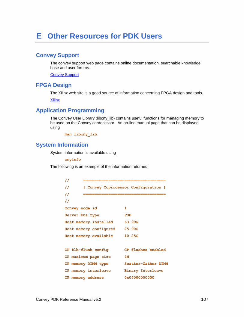
Convey PDK Reference Manual v5.2 107
E Other Resources for PDK Users
Convey Support
The convey support web page contains online documentation, searchable knowledge base and user forums.
Convey Support
FPGA Design
The Xilinx web site is a good source of information concerning FPGA design and tools.
Xilinx
Application Programming
The Convey User Library (libcny_lib) contains useful functions for managing memory to be used on the Convey coprocessor. An on-line manual page that can be displayed using
man libcny_lib
System Information
System information is available using
cnyinfo
The following is an example of the information returned:
// ====================================
// | Convey Coprocessor Configuration |
// ====================================
//
Convey node id 1
Server bus type FSB
Host memory installed 63.99G
Host memory configured 25.90G
Host memory available 10.25G
CP tlb-flush config CP flushes enabled
CP maximum page size 4M
CP memory DIMM type Scatter-Gather DIMM
CP memory interleave Binary Interleave
CP memory address 0x04000000000
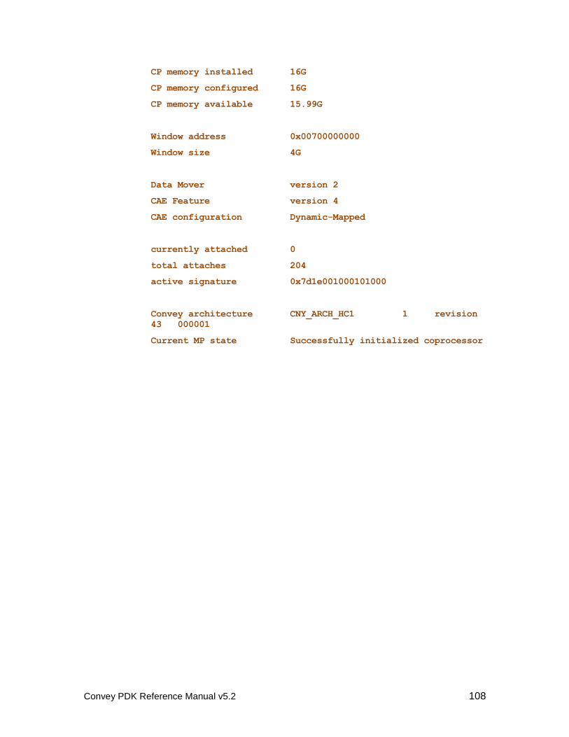
Convey PDK Reference Manual v5.2 108
CP memory installed 16G
CP memory configured 16G
CP memory available 15.99G
Window address 0x00700000000
Window size 4G
Data Mover version 2
CAE Feature version 4
CAE configuration Dynamic-Mapped
currently attached 0
total attaches 204
active signature 0x7d1e001000101000
Convey architecture CNY_ARCH_HC1 1 revision
43 000001
Current MP state Successfully initialized coprocessor
Convey PDK Reference Manual v5.2 109
F Customer Support Procedures
Email [email protected]
Web Browse to conveycomputer.com, and click on
Convey Customer Support.