Embed Size (px)
Citation preview
18 Oilfield Review
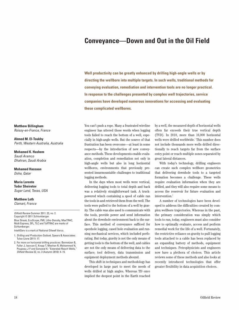
Conveyance—Down and Out in the Oil Field
Well productivity can be greatly enhanced by drilling high-angle wells or by
directing the wellbore into multiple targets. In such wells, traditional methods for
conveying evaluation, remediation and intervention tools are no longer practical.
In response to the challenges presented by complex well trajectories, service
companies have developed numerous innovations for accessing and evaluating
these complicated wellbores.
Matthew BillinghamRoissy-en-France, France
Ahmed M. El-Toukhy Perth, Western Australia, Australia
Mohamed K. HashemSaudi AramcoDhahran, Saudi Arabia
Mohamed HassaanDoha, Qatar
Maria LorenteTodor SheiretovSugar Land, Texas, USA
Matthew LothClamart, France
Oilfield Review Summer 2011: 23, no. 2. Copyright © 2011 Schlumberger.Blue Streak, EcoScope, FMI, Litho-Density, MaxTRAC, Multi Express, SFL, TLC and TuffTRAC are marks of Schlumberger.IntelliServ is a mark of National Oilwell Varco.
You can’t push a rope. Many a frustrated wireline engineer has uttered those words when logging tools failed to reach the bottom of a well, espe-cially in high-angle wells. But the source of that frustration has been overcome—at least in some respects—by the introduction of new convey-ance methods. These developments enable evalu-ation, completion and remediation not only in high-angle wells but also in long horizontal wellbores, environments that previously pre-sented insurmountable challenges to traditional logging methods.
In the days when most wells were vertical, delivering logging tools to total depth and back was a relatively straightforward task. A truck- powered winch containing a spool of cable ran the tools in and retrieved them from the well. The tools were pulled to the bottom of a well by grav-ity. The cable was also used to communicate with the tools, provide power and send information about the downhole environment back to the sur-face. This method of conveyance sufficed for openhole logging, cased hole evaluation and run-ning mechanical services, which included perfo-rating. But today, gravity is not the only means of getting tools to the bottom of the well, and cables are not the only means of delivering data to the surface; tool delivery, data transmission and equipment deployment methods abound.
This shift in techniques and methodology has developed in large part to meet the needs of wells drilled at high angles. Whereas TD once implied the deepest point in the Earth reached
by a well, the measured depth of horizontal wells often far exceeds their true vertical depth (TVD). In 2010, more than 16,000 horizontal wells were drilled worldwide.1 This number does not include thousands more wells drilled direc-tionally to reach targets far from the surface entry point or reach multiple zones separated by great lateral distances.
With today’s technology, drilling engineers can create such complex wellbore geometries that delivering downhole tools to a targeted formation becomes a challenge. These wells require evaluation information when they are drilled, and they will also require some means to access the reservoir for future evaluation and intervention.2
A number of technologies have been devel-oped to address the difficulties created by com-plex wellbore trajectories. Whereas in the past, the primary consideration was simply which tools to run, today, engineers must also consider how to optimally evaluate, access and perform remedial work for the life of a well. Fortunately, the restrictive reliance on gravity to pull logging tools attached to a cable has been replaced by an expanding battery of methods, equipment and techniques. Petrophysicists and engineers now have a plethora of choices. This article reviews some of these methods and also looks at recently introduced technologies that offer greater flexibility in data acquisition choices.
1. Drilling and Production Outlook. Spears & Associates: Tulsa (June 2011): 17.
2. For more on horizontal drilling practices: Bennetzen B, Fuller J, Isevcan E, Krepp T, Meehan R, Mohammed N, Poupeau J-F and Sonowal K: “Extended-Reach Wells,” Oilfield Review 22, no. 3 (Autumn 2010): 4–15.
41615schD5R1.indd 18 8/12/11 8:02 PM
CCCCCCCCCCCCCCCCCCCCCCCCCCCCCCCCCCCCCCCCCCCCCCCCCCCCCCCCCCCCCCCCCCCCCCCCCCCCCCCCCCCCCCCCCCCCCCCCCCCCCCCCCCCooooooooooooooooooooooooooooooooooooooooooooooooooooooooooooooooooooooooooooooooiiiiiiiiiiiiiiiiiiiiiiiiiiiiiiiiiiiiiiiiiiiiiiiiiiilllllllllllllllllllllllllllllllllllllllllllllllllllllllllllllllllllllllllleeeeeeeeeeeeeeeeeeeeeeeeeeeeeeeeeeeeeeeeeeeeeeeeeeeeeeeeeeeeeeeeeeeeeeeeeeeeedddddddddddddddddddddddddddddddddddddddddddddddddddddddddddddddddddddddddddddddddddddddd TTTTTTTTTTTTTTTTTTTTTTTTTTTTTTTTTTTTTTTTTTTTTTTTTTTTTTTTTTTTTTTTTTTTTTTTTTuuuuuuuuuuuuuuuuuuuuuuuuuuuuuuuuuuuuuuuuuuuuuuuuuuuuuuuuubbbbbbbbbbbbbbbbbbbbbbbbbbbbbbbbbbbbbbbbbbbbbbbbbbbbbbbiiiiiiiiiiiiiiiiiiiiiiiiiiiiiiiiinnnnnnnnnnnnnnnnnnnnnnnnnnnnnnnnnnnnnnnnnnnnnnnnnnnnnnnnnnggggggggggggggggggggggggggggggggggggggggggggggggggggggggggggggggggggggggggggggggggggggggggggggggggggggggg
Coiled Tubing
WWWWWWWWWWWWWWWWWWWWWWWWWWWWWWWWWWWWWWWWWWWWWWWWWWWWWWiiiiiiiiiiiiiiiiiiiiiiiiiiiiiiiiiirrrrrrrrrrrrrrrrrrrrrrrrrrrrrrrrrrrrrreeeeeeeeeeeeeeeeeeeeeeeeeeeeeeeeeeeeeeeeeeeeeeeeeeeeeelllllllllllllllllllllllllllllllliiiiiiiiiiiiiiiiiiiiiiiiiiiiiiiiiiiiiiiiiiiiinnnnnnnnnnnnnnnnnnnnnnnnnnnnnnnnnnnnnnnnnnnnnnnnnnnnnnnnnnnnnnnnnnneeeeeeeeeeeeeeeeeeeeeeeeeeeeeeeeeeeeeeeeeeeeeeeeeeeeeeeeeeeeeeeeeeeeeeeWireline
LLLLLLLLLLLLLLLLLLLLLLLLLLLLLLLLLLLLLLLLLLLLLLLLLLLLLLLLLLLLLLLLLLLLLLLLLLLLLLLLLLLLLLLLLLLLLLLLLLLLLLLLLLLLLLLLLLLLLLLLLLLLLLLLLLLLLLLLLLLLLLLLLLLLLLLLLLLLLLLLLLLLLLLLLLLLLooooooooooooooooooooooooooooooooooooooooooooooooooooooooooooooooooooooooooooooooooooooooooooooooooooooooooooooooooooooooooooooooooooooooooooooooooooooooooooooooogggggggggggggggggggggggggggggggggggggggggggggggggggggggggggggggggggggggggggggggggggggggggggggggggggggggggggggggggggggggggggggggggggggggggggggggggggggggggggggggggggggggggggggggggggggggggggggggggggggggggggggggggggggggggggggggggiiiiiiiiiiiiiiiiiiiiiiiiiiiiiiiiiiiiiiiiiiiiiiiiiiiiiiiiiiiiiiiiiiiinnnnnnnnnnnnnnnnnnnnnnnnnnnnnnnnnnnnnnnnnnnnnnnnnnnnnnnnnnnnnnnnnnnnnnnnnnnnnnnnnnnnnnnnnnnnnnnnngggggggggggggggggggggggggggggggggggggggggggggggggggggggggggggggggggggggggggggggggggggggggggggggg TTTTTTTTTTTTTTTTTTTTTTTTTTTTTTTTTTTTTTTTTTTTTTTTTTTTTTTTTTTTTTTTTTTTTTTTTTTTTTTTTTTTTTTTTTTTTTTTTTTTTTTTTTTooooooooooooooooooooooooooooooooooooooooooooooooooooooooooooooooooooooooooooooooooooooooooooooooooooooooooooooooooooooooooooooooooooooooooooooooooooooooooooooooooooooooooooooooooooooooooooooollllllllllllllllllllllllllllllllllllllllllllllllllllllllllllllllllllsssssssssssssssssssssssssssssssssssssssssssssssssssssssssssssssssssssssss ooooooooooooooooooooooooooooooooooooooooooooooooooooooooooooooooooooooooooooooooooooooonnnnnnnnnnnnnnnnnnnnnnnnnnnnnnnnnnnnnnnnnnnnnnnnnnnnnnnnnnnnnnnnnnnnnnnnnnnnnnnnnnnn DDDDDDDDDDDDDDDDDDDDDDDDDDDDDDDDDDDDDDDDDDDDDDDDDDDDDDDDDDDDDDDDDDDDDDDDDDDDDDDDDDDDDDDDDDDDrrrrrrrrrrrrrrrrrrrrrrrrrrrrrrrrrrrrrrrrrrrrrrrrrrrrrrrrrrrrrrrrrrrriiiiiiiiiiiiiiiiiiiiiiiiiiiiiiiiiiiiiiiiiiiiiiiiiiiiiiiiiiiiiiiiiiilllllllllllllllllllllllllllllllllllllllllllllllllllllllllllllllllllllllllllllllllllllllllllllllllllllllllllllllllllllllllllllllllllllllllllllllllllllppppppppppppppppppppppppppppppppppppppppppppppppppppppppppppppppppppppppppppppppppppiiiiiiiiiiiiiiiiiiiiiiiiiiiiiiiiiiiiiiiiiiiiiiiippppppppppppppppppppppppppppppppppppppppppppppeeeeeeeeeeeeeeeeeeeeeeeeeeeeeeeeeeeeeeeeeeeeeeeeeeeeeeeeeee
Logging Tools on Drillpipe
DDDDDDDDDDDDDDDDDDDDDDDDDDDDDDDDDDDDDDDDDDDDDDDDDDDDDDDDDDDDDDDDDDDDDDDDDDDDDDDDDDDDooooooooooooooooooooooooooooooooooooooooooowwwwwwwwwwwwwwwwwwwwwwwwwwwwwwwwwwwwwwwwnnnnnnnnnnnnnnnnnnnnnnnnnnnnhhhhhhhhhhhhhhhhhhhhhhhhhhhhhhhhhhhhhhhhoooooooooooooooooooooooooooooooooooooooooooooooooooooooooooooooolllllllllllllllllllllllllllllllllllllllllllllllllleeeeeeeeeeeeeeeeeeeeeeeeeeeeeeeeeeeeeeeeeeeeeeeeeeeeeeeeeeeeeeeeeeeeee TTTTTTTTTTTTTTTTTTTTTTTTTTTTTTTTrrrrrrrrrrrrrrrrrrrrrrrrrrraaaaaaaaaaaaaaaaaaaaaaaaaaaaaaaaaaaaaaaaaaaaaaaaaaaaaaacccccccccccccccccccccccccccccccccccccccccccccccccccccccccccccccccccccccttttttttttttttttttttttttttttttttttttttttttttttttttttttttttoooooooooooooooooooooooooooooooooooooooooooooooooooooooooooooooooooooooooooorrrrrrrrrrrrrrrrrrrrrrr
Downhole Tractor
LLLLLLLLLLLLLLLLLLLLLLLLLLLLLLLLLLLLLLLLLLLLLLLLLLLLLLLLLLLLLLLLLLLLLLLLLLLLLLLLLLLLLLLLLLLLLLLLLLLLLLLLLLLLLLLLLLLLLLLLLLLLLLLLLLLLLLLLLLLLLLLLLLLLLLLLLLLLoooooooooooooooooooooooooooooooooooooooooooooooooooooooooooooooooooooooooooooooooooooooooooooooooooooooooooooooooooooooooooooooooooooooooooooooooooooooooooooooooooogggggggggggggggggggggggggggggggggggggggggggggggggggggggggggggggggggggggggggggggggggggggggggggggggggggggggggggggggggggggggggggggggggggggggggggggggggggggggggggggggggggggggggggggggggggggggggggggggggggggggggggggggggggggggggggggggggggggggggggggggggggggggggggggggggggggggggggggggggggggggggggggggggggggggggggggggggggggggggggggggggggggggggggggggggggggggggggggggiiiiiiiiiiiiiiiiiiiiiiiiiiiiiiiiiiiiiiiiiiiiiiiiiiiiiiiiiiiiiiiiiiiiiiiiiiiiiiiiiiinnnnnnnnnnnnnnnnnnnnnnnnnnnnnnnnnnnnnnnnnnnnnnnnnnnnnnnnnnnnnnnnnnnnnnnnngggggggggggggggggggggggggggggggggggggggggggggggggggggggggggggggggggggggggggg WWWWWWWWWWWWWWWWWWWWWWWWWWWWWWWWWWWWWWWWWWWWWWWWWWWWWWWWWWWWWWWWWWWWWWWWWWWWWWWWWWWWWWWWWWWWWWhhhhhhhhhhhhhhhhhhhhhhhhhhhhhhhhhhhhhhhhhhhhhhhhhhhhhhhhhhhhhhhhhhhhhhhhhhhhhhhhhhhhhhhhhhhhhhhhhhhhhhhhhhhhhhhiiiiiiiiiiiiiiiiiiiiiiiiiiiiiiiiiiiiiiiiiiiiiiiiiiilllllllllllllllllllllllllllllllllllllllllllleeeeeeeeeeeeeeeeeeeeeeeeeeeeeeeeeeeeeeeeeeeeeeeeeeeeeeeeeeeeeeeeee DDDDDDDDDDDDDDDDDDDDDDDDDDDDDDDDDDDDDDDDDDDDDDDDDDDDDDDDDDDDDDDDDDDDrrrrrrrrrrrrrrrrrrrrrrrrrrrrrrrrrrrrrriiiiiiiiiiiiiiiiiiiiiiiiiiiiiiiiiiiiiiiiiiiiiiiiiiillllllllllllllllllllllllllllllllllllllllllllllllllllllllllllllllllllllllllllllllllllllllllliiiiiiiiiiiiiiiiiiiiiiiiiiiiiiiiiiiiinnnnnnnnnnnnnnnnnnnnnnnnnnnnnnnnnnnnnnnnnnnnnnnnnngggggggggggggggggggggggggggggggggggggggggggggggggggggggggggggggggggg
Logging While Drilling
Summer 2011 19
41615schD5R1.indd 19 8/12/11 8:02 PM
20 Oilfield Review
Getting to the BottomConveyance consists of more than the mecha-nisms of pulling and pushing tools downhole. Its greater purpose is to address the challenges cre-ated by wellbore environments. These challenges include deploying tools at the surface, overcom-ing frictional forces, maneuvering past obstacles and adapting to unforeseen downhole conditions. Flexibility and adaptability are important factors that engineers consider when deploying tools downhole, but their tool choices often dictate the method of conveyance.
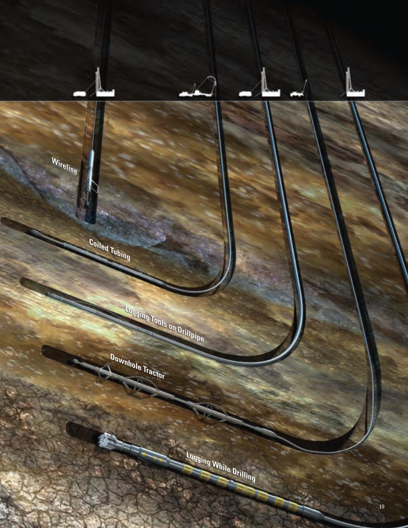
Conveyance methods can be grouped into two basic types: cable conveyed and pipe conveyed (above). Within both categories are variations
and hybrid solutions that blend elements of the other. The various methods come with trade-offs, strengths and weaknesses, so there is rarely a perfect solution.
Cable-conveyed tools have a long history. The first electric log, acquired at Pechelbronn field in Alsace, France, on September 5, 1927, was run on a cable. The survey instrument was lowered 300 m [980 ft] into the well, and subsurface measure-ments were plotted by hand as the tool was slowly retrieved using a manually operated winch (next page, top right). For the next 50 years, the logging industry remained tethered to a cable, even as log-ging tools evolved to include extremely complex measurements that demand high data rates.3
Surface units used for acquisition also became more and more sophisticated. But the well logging landscape experienced its most dramatic transfor-mation in the 1980s with the introduction of logging-while-drilling (LWD) tools.
LWD tools are an integral part of the drill-string bottomhole assembly (BHA). In the early days, measurements were fairly basic; they included gamma ray and resistivity, followed by the addition of porosity measurements. The tools communicate via a series of pressure pulses transmitted through the circulating drilling mud to convey commands downhole and deliver data to the surface. These pressure pulses are encoded with data about well conditions, the status of the BHA and the formations encountered by the bit.
Mud pulse telemetry transmits data at rates that are several orders of magnitude lower than those achieved using logging cables; but, given the time required for drilling operations, this method has generally proved to be sufficient. Other transmission methods are available; for example, electromagnetic telemetry is used as an alternative to mud pulse telemetry in air or foam drilling. And more recently, wired drillpipe, which can send data using an imbedded trans-mission cable, has been introduced.
Wired drillpipe promises high data rates: 57,000 bits per second compared with 10 bits per second with mud pulse telemetry. Commercial transmission systems, such as the IntelliServ Broadband Network, are currently available, although this technology has yet to replace mud pulse telemetry as the method of choice for ser-vice companies and operators.
Whichever method is used, the ability to acquire real-time data from near the bit not only offers a substitute for wireline logging, but also has led to a revolution in the application of rotary steerable drilling systems, ushering in a new age of horizontal and extended-reach drilling.4 Using real-time information provided by LWD tools, directional drillers can remotely steer and guide the bit to specific targets, making precise correc-tions in wellbore trajectory.
As well trajectories shifted from vertical to horizontal, LWD data, in many cases, supplanted traditional wireline logging for formation evalua-tion. Meanwhile, the quality and scope of LWD data have improved, and sophisticated tool offer-ings are now available while drilling. For instance, the EcoScope multifunction LWD service offers resistivity, porosity, azimuthal density, ultrasonic caliper, capture spectroscopy and azimuthal
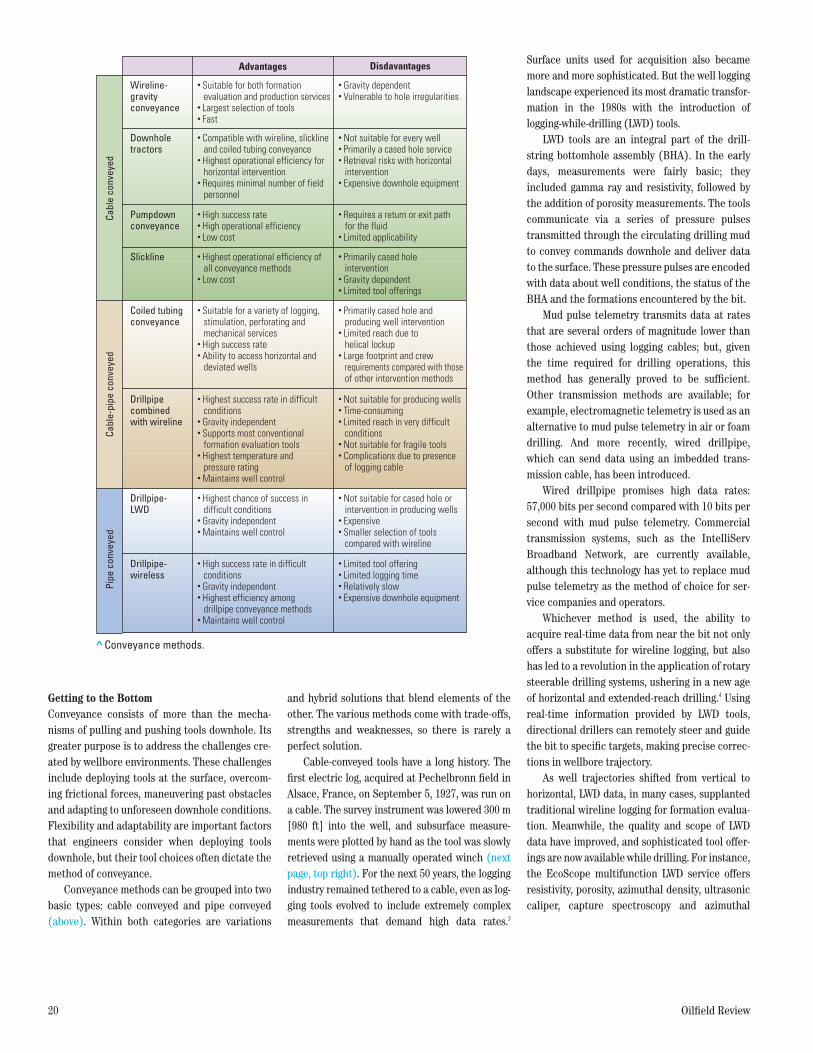
Advantages Disdavantages
Wireline-gravityconveyance
Downhole tractors
Slickline
Coiled tubingconveyance
Drillpipe- LWD
Drillpipe- wireless
Pumpdownconveyance
Drillpipe combinedwith wireline
• Gravity dependent• Vulnerable to hole irregularities
• Not suitable for every well• Primarily a cased hole service• Retrieval risks with horizontal intervention• Expensive downhole equipment
• Primarily cased hole intervention• Gravity dependent• Limited tool offerings
• Primarily cased hole and producing well intervention• Limited reach due to helical lockup• Large footprint and crew requirements compared with those of other intervention methods
• Not suitable for cased hole or intervention in producing wells• Expensive• Smaller selection of tools compared with wireline
• Not suitable for producing wells• Time-consuming• Limited reach in very difficult conditions• Not suitable for fragile tools• Complications due to presence of logging cable
• Limited tool offering• Limited logging time• Relatively slow• Expensive downhole equipment
• Requires a return or exit path for the fluid• Limited applicability
• Suitable for both formation evaluation and production services• Largest selection of tools• Fast
• Highest operational efficiency of all conveyance methods• Low cost
• Suitable for a variety of logging, stimulation, perforating and mechanical services• High success rate• Ability to access horizontal and deviated wells
• Highest chance of success in difficult conditions• Gravity independent• Maintains well control
• Highest success rate in difficult conditions• Gravity independent• Supports most conventional formation evaluation tools• Highest temperature and pressure rating• Maintains well control
• High success rate in difficult conditions• Gravity independent• Highest efficiency among drillpipe conveyance methods• Maintains well control
• High success rate• High operational efficiency• Low cost
• Compatible with wireline, slickline and coiled tubing conveyance• Highest operational efficiency for horizontal intervention• Requires minimal number of field personnel
Oilfield ReviewSUMMER 11 Conveyance Fig. Table 1ORSUM11-CONVY Table 1
Cabl
e co
nvey
edCa
ble-
pipe
con
veye
dPi
pe c
onve
yed
> Conveyance methods.
41615schD5R1.indd 20 8/12/11 8:02 PM
Summer 2011 21
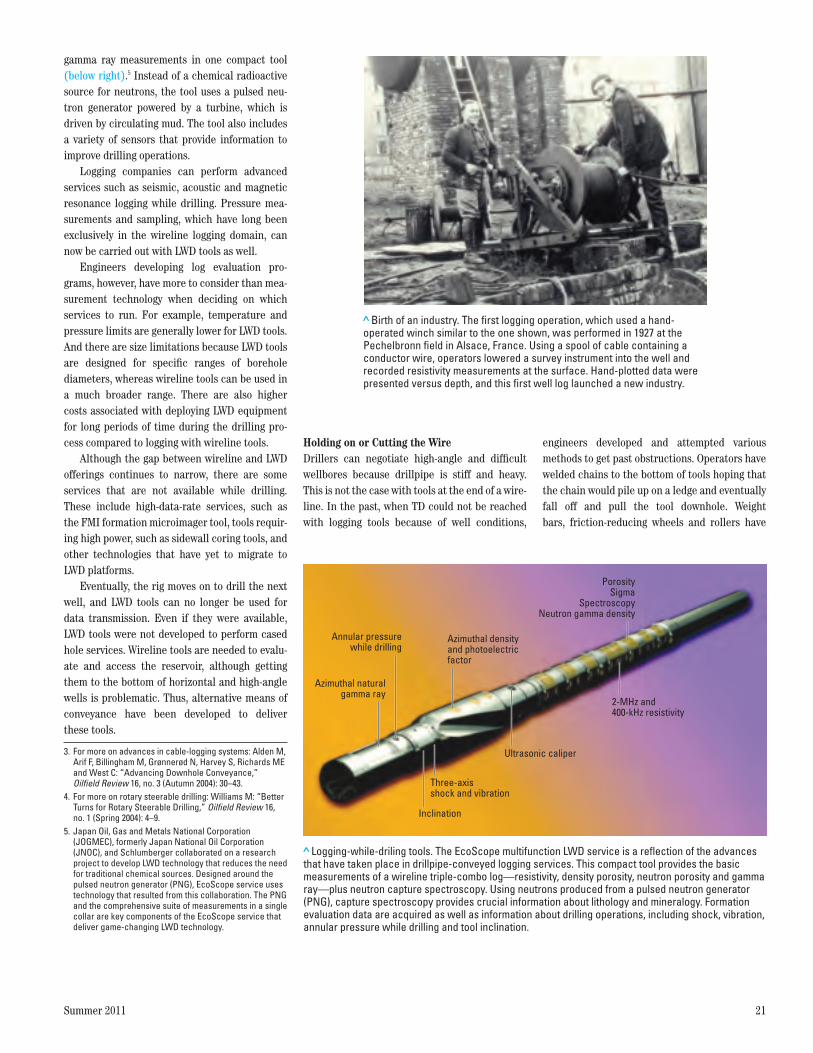
gamma ray measurements in one compact tool (below right).5 Instead of a chemical radioactive source for neutrons, the tool uses a pulsed neu-tron generator powered by a turbine, which is driven by circulating mud. The tool also includes a variety of sensors that provide information to improve drilling operations.
Logging companies can perform advanced services such as seismic, acoustic and magnetic resonance logging while drilling. Pressure mea-surements and sampling, which have long been exclusively in the wireline logging domain, can now be carried out with LWD tools as well.
Engineers developing log evaluation pro-grams, however, have more to consider than mea-surement technology when deciding on which services to run. For example, temperature and pressure limits are generally lower for LWD tools. And there are size limitations because LWD tools are designed for specific ranges of borehole diameters, whereas wireline tools can be used in a much broader range. There are also higher costs associated with deploying LWD equipment for long periods of time during the drilling pro-cess compared to logging with wireline tools.
Although the gap between wireline and LWD offerings continues to narrow, there are some services that are not available while drilling. These include high-data-rate services, such as the FMI formation microimager tool, tools requir-ing high power, such as sidewall coring tools, and other technologies that have yet to migrate to LWD platforms.
Eventually, the rig moves on to drill the next well, and LWD tools can no longer be used for data transmission. Even if they were available, LWD tools were not developed to perform cased hole services. Wireline tools are needed to evalu-ate and access the reservoir, although getting them to the bottom of horizontal and high-angle wells is problematic. Thus, alternative means of conveyance have been developed to deliver these tools.
Holding on or Cutting the WireDrillers can negotiate high-angle and difficult wellbores because drillpipe is stiff and heavy. This is not the case with tools at the end of a wire-line. In the past, when TD could not be reached with logging tools because of well conditions,
engineers developed and attempted various methods to get past obstructions. Operators have welded chains to the bottom of tools hoping that the chain would pile up on a ledge and eventually fall off and pull the tool downhole. Weight bars, friction-reducing wheels and rollers have
3. For more on advances in cable-logging systems: Alden M, Arif F, Billingham M, Grønnerød N, Harvey S, Richards ME and West C: “Advancing Downhole Conveyance,” Oilfield Review 16, no. 3 (Autumn 2004): 30–43.
4. For more on rotary steerable drilling: Williams M: “Better Turns for Rotary Steerable Drilling,” Oilfield Review 16, no. 1 (Spring 2004): 4–9.
5. Japan Oil, Gas and Metals National Corporation (JOGMEC), formerly Japan National Oil Corporation (JNOC), and Schlumberger collaborated on a research project to develop LWD technology that reduces the need for traditional chemical sources. Designed around the pulsed neutron generator (PNG), EcoScope service uses technology that resulted from this collaboration. The PNG and the comprehensive suite of measurements in a single collar are key components of the EcoScope service that deliver game-changing LWD technology.
> Birth of an industry. The first logging operation, which used a hand-operated winch similar to the one shown, was performed in 1927 at the Pechelbronn field in Alsace, France. Using a spool of cable containing a conductor wire, operators lowered a survey instrument into the well and recorded resistivity measurements at the surface. Hand-plotted data were presented versus depth, and this first well log launched a new industry.
Oilfield ReviewSUMMER 11 Conveyance Fig. 1ORSUM11-CONVY 1
> Logging-while-driling tools. The EcoScope multifunction LWD service is a reflection of the advances that have taken place in drillpipe-conveyed logging services. This compact tool provides the basic measurements of a wireline triple-combo log—resistivity, density porosity, neutron porosity and gamma ray—plus neutron capture spectroscopy. Using neutrons produced from a pulsed neutron generator (PNG), capture spectroscopy provides crucial information about lithology and mineralogy. Formation evaluation data are acquired as well as information about drilling operations, including shock, vibration, annular pressure while drilling and tool inclination.
Oilfield ReviewSUMMER 11 Conveyance Fig. 2ORSUM11-CONVY 2
Azimuthal naturalgamma ray
Azimuthal densityand photoelectric factor
PorositySigma
SpectroscopyNeutron gamma density
Inclination
Three-axisshock and vibration
2-MHz and 400-kHz resistivity
Ultrasonic caliper
Annular pressurewhile drilling
41615schD5R1.indd 21 8/12/11 8:02 PM
22 Oilfield Review
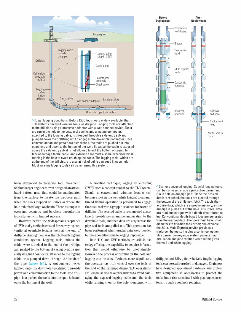
> Carrier conveyed logging. Special logging tools can be conveyed inside a protective carrier and run in hole on drillpipe (left). Once the desired depth is reached, the tools are ejected through the bottom of the drillpipe (right). The tools then acquire data, which are stored in memory, as the drillpipe is pulled out of the hole. At surface, data are read and merged with a depth-time reference log. Conventional depth-based logs are generated from the merged data. The tools must have small diameters to fit inside the carrier; one example, the 21/4-in. Multi Express service provides a triple-combo toolstring plus a sonic tool option. This carrier conveyance system permits fluid circulation and pipe rotation while running into the well and while logging.
Connectionto drillpipe
BeforeDeployment
AfterDeployment
Ejector
Deploymenthead
Deploymenthead
Multi Expresstools
Multi Expresstools
Concentrichousings
Receiverand shoe
Receiverand shoe
Oilfield ReviewSUMMER 11 Conveyance Fig. 4ORSUM11-CONVY 4
been developed to facilitate tool movement. Schlumberger engineers even designed an articu-lated bottom nose that could be manipulated from the surface to locate the wellbore path when the tools stopped on ledges or where the hole exhibited large washouts. These attempts to overcome geometry and borehole irregularities typically met with limited success.
However, before the widespread acceptance of LWD tools, methods existed for conveying con-ventional openhole logging tools at the end of drillpipe. Among them was the TLC tough logging conditions system. Logging tools, minus the cable, were attached to the end of the drillpipe and pushed to the bottom of casing. Next, a spe-cially designed connector, attached to the logging cable, was pumped down through the inside of the pipe (above left). A wet-connect device latched onto the downhole toolstring to provide power and communication to the tools. The drill-pipe then pushed the tools into the open hole and on to the bottom of the well.
A modified technique, logging while fishing (LWF), uses a concept similar to the TLC system. Should a conventional wireline logging tool become stuck in the well while logging, a cut-and-thread fishing operation is performed to engage the stuck tool with a grapple attached to the end of drillpipe. The severed cable is reconnected at sur-face to provide power and communication to the downhole tools, and then data are acquired as the pipe and tools are pulled out. This operation has been performed when crucial data were needed but hole conditions made logging impossible.
Both TLC and LWF methods are still in use today, offering the capability to acquire informa-tion that would otherwise be unobtainable. However, the process of running in the hole and logging can be slow. Perhaps more significant, the operator has little control over the tools at the end of the drillpipe during TLC operations. Drillers must also take precautions to avoid dam-aging the exposed logging cable and the tools while running them in the hole. Compared with
drillpipe and BHAs, the relatively fragile logging tools can be easily crushed or damaged. Engineers have designed specialized hardware and protec-tive equipment as accessories to protect the tools, but a risk associated with pushing exposed tools through open hole remains.
> Tough logging conditions. Before LWD tools were widely available, the TLC system conveyed wireline tools via drillpipe. Logging tools are attached to the drillpipe using a crossover adaptor with a wet-connect device. Tools are run in the hole to the bottom of casing, and a mating connector, attached to the logging cable, is threaded through a side entry sub and pumped down the drillstring until it engages the downhole connector. Once communication and power are established, the tools are pushed out into open hole and down to the bottom of the well. Because the cable is exposed above the side entry sub, it is not allowed to exit the bottom of casing for fear of damage to the cable, and extreme care must also be exercised while running in the hole to avoid crushing the cable. The logging tools, which are at the end of the drillpipe, are also at risk of being damaged in open hole. Most wireline logging tools can be run using this system.
Oilfield ReviewSUMMER 11 Conveyance Fig. 3ORSUM11-CONVY 3
Cable clamp
Logging cablesetup in CSES
Cable sideentry sub
(CSES)Packoff sealassemblyCheck valve
Logging stringCasing shoe
Horizontal openhole section
Drillpipe
Logging cableoutsidedrillpipe
Loggingcable
insidedrillpipe
Logging truck
Wet-connect adaptor
41615schD5R1.indd 22 8/12/11 8:02 PM
Summer 2011 23
Even with protective hardware, openhole log-ging tools may encounter ledges, bridged sec-tions of open hole and large washed-out wellbores, making it impossible to push the tools to bottom. Drillers often attempt pipe rotation to get around obstructions, which is not an option when tools are attached with TLC operations.
A recent adaptation of the TLC concept has been developed that uses drillpipe to convey log-ging tools. The main differences are that the tools are protected inside a carrier while they are being run in the hole and no logging cable is required (previous page, top right). Once the drillstring reaches the logging depth, the field engineer uses an ejection mechanism to deploy battery-powered tools. Extended beneath the bottom of the drill-pipe, these tools acquire downhole data, which are stored in memory while the drillpipe is being pulled out of the hole. Pipe movement is recorded versus time during retrieval. At surface, the time-based data from downhole are recovered using a laptop computer and then merged with the depth data from pipe movement to generate conven-tional depth logs. A logging truck is not required.
Because they are deployed inside drillpipe, the tools must have a smaller diameter than conventional logging equipment. The recently introduced Multi Express slim, multiconveyance formation evaluation platform is an example of a set of tools that can be deployed using the protec-tive drillpipe carrier. With a 21/4-in. [5.7-cm] diam-eter, these tools fit inside the 5-in. [12.7-cm] OD carrier with enough clearance to circulate mud downhole. The ability to circulate is an important feature for running drillpipe into the well, espe-cially in long horizontal openhole sections in which cuttings can accumulate.
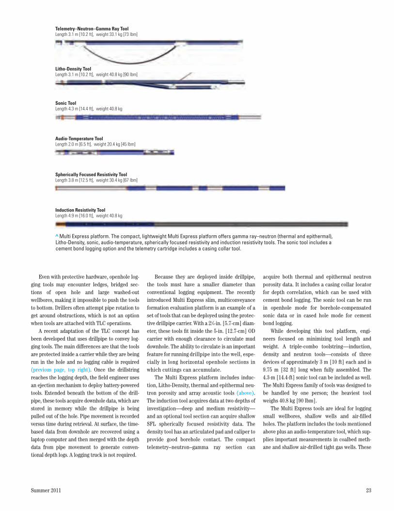
The Multi Express platform includes induc-tion, Litho-Density, thermal and epithermal neu-tron porosity and array acoustic tools (above). The induction tool acquires data at two depths of investigation—deep and medium resistivity—and an optional tool section can acquire shallow SFL spherically focused resistivity data. The density tool has an articulated pad and caliper to provide good borehole contact. The compact telemetry–neutron–gamma ray section can
acquire both thermal and epithermal neutron porosity data. It includes a casing collar locator for depth correlation, which can be used with cement bond logging. The sonic tool can be run in openhole mode for borehole-compensated sonic data or in cased hole mode for cement bond logging.
While developing this tool platform, engi-neers focused on minimizing tool length and weight. A triple-combo toolstring—induction, density and neutron tools—consists of three devices of approximately 3 m [10 ft] each and is 9.75 m [32 ft] long when fully assembled. The 4.3-m [14.4-ft] sonic tool can be included as well. The Multi Express family of tools was designed to be handled by one person; the heaviest tool weighs 40.8 kg [90 lbm].
The Multi Express tools are ideal for logging small wellbores, shallow wells and air-filled holes. The platform includes the tools mentioned above plus an audio-temperature tool, which sup-plies important measurements in coalbed meth-ane and shallow air-drilled tight gas wells. These
>Multi Express platform. The compact, lightweight Multi Express platform offers gamma ray–neutron (thermal and epithermal), Litho-Density, sonic, audio-temperature, spherically focused resistivity and induction resistivity tools. The sonic tool includes a cement bond logging option and the telemetry cartridge includes a casing collar tool.
Oilfield ReviewSUMMER 11 Conveyance Fig. 5ORSUM11-CONVY 5
Sonic ToolLength 4.3 m [14.4 ft], weight 40.8 kg
Audio-Temperature ToolLength 2.0 m [6.5 ft], weight 20.4 kg [45 lbm]
Spherically Focused Resistivity ToolLength 3.8 m [12.5 ft], weight 30.4 kg [67 lbm]
Induction Resistivity ToolLength 4.9 m [16.0 ft], weight 40.8 kg
Telemetry–Neutron–Gamma Ray ToolLength 3.1 m [10.2 ft], weight 33.1 kg [73 lbm]
Litho-Density ToolLength 3.1 m [10.2 ft], weight 40.8 kg [90 lbm]
41615schD5R1.indd 6 8/19/11 11:05 PM
24 Oilfield Review
types of wells can be difficult to evaluate with conventional logging units because the wells have small drilling pads and the rigs move quickly from wellsite to wellsite.
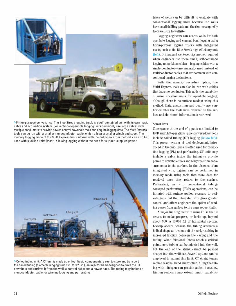
Logging engineers can access wells for both openhole logging and cement bond logging using fit-for-purpose logging trucks with integrated masts, such as the Blue Streak high-efficiency unit (left). Drilling and workover rigs are not required when engineers use these small, self-contained logging units. Monocables—logging cables with a single conductor—are generally used instead of multiconductor cables that are common with con-ventional logging tool systems.
With the memory recording option, the Multi Express tools can also be run with cables that have no conductor. This adds the capability of using slickline units for openhole logging, although there is no surface readout using this method. Data acquisition and quality are con-firmed after the tools have returned to the sur-face and the stored information is retrieved.
Smart IronConveyance at the end of pipe is not limited to LWD and TLC operations; pipe-conveyed methods include coiled tubing (CT) logging (below left). This proven system of tool deployment, intro-duced in the mid-1980s, is often used for produc-tion logging (PL) and perforating. CT units may include a cable inside the tubing to provide power to downhole tools and relay real-time mea-surements to the surface. In the absence of an integrated wire, logging can be performed in memory mode using tools that store data for retrieval once they return to the surface. Perforating, as with conventional tubing- conveyed perforating (TCP) operations, can be initiated with surface-applied pressure to acti-vate guns, but the integrated wire gives greater control and offers engineers the option of send-ing power from surface to fire guns sequentially.
A major limiting factor in using CT is that it ceases to make progress, or locks up, beyond about 900 m [3,000 ft] of horizontal section. Lockup occurs because the tubing assumes a helical shape as it comes off the reel, resulting in increased friction between the casing and the tubing. When frictional forces reach a critical point, more tubing can be injected into the well, but the end of the string cannot be pushed deeper into the wellbore. Several options can be employed to extend this limit: CT straighteners reduce residual bend and friction, filling the tub-ing with nitrogen can provide added buoyancy, friction reducers may extend length capability
> Fit-for-purpose conveyance. The Blue Streak logging truck is a self-contained unit with its own mast, cable and acquisition system. Conventional openhole logging units commonly use large cables with multiple conductors to provide power, control downhole tools and acquire logging data. The Multi Express tools can be run with a smaller monoconductor cable, which allows a smaller winch and spool. The memory logging mode of the Multi Express tools, utilized with the drillpipe-carrier method, can also be used with slickline units (inset), allowing logging without the need for surface-supplied power.
Oilfield ReviewSUMMER 11 Conveyance Fig. 6ORSUM11-CONVY 6
> Coiled tubing unit. A CT unit is made up of four basic components: a reel to store and transport the coiled tubing (diameter ranging from 1 in. to 3.25 in.), an injector head designed to drive the CT downhole and retrieve it from the well, a control cabin and a power pack. The tubing may include a monoconductor cable for wireline logging and perforating.
Oilfield ReviewSUMMER 11 Conveyance Fig. 7ORSUM11-CONVY 7
Power packControl cabin
Tubing reel
Injector head
41615schD5R1.indd 24 8/12/11 8:02 PM
Summer 2011 25
and larger diameter tubing can often go deeper but requires much larger surface equipment.6
ExxonMobil, in developing the Sakhalin Island land-based offshore Chayvo field in Russia, tested a hydraulically actuated CT tractor to extend the reach of operations.7 The field is located offshore, but drilling and production facilities are located on land. To access their wells, ExxonMobil engi-neers needed to increase the CT range beyond that possible with existing hardware. Although much of the equipment was standard for CT units, engineers made several modifications to accom-modate a 35,006-ft [10,670-m] reel of 23/8-in. OD coiled tubing.
This hydraulic CT tractor was powered and controlled by differential pressure between the tubing and the annulus. The assembly was tested prior to job commencement and had 9,700 lbm [43,148 kg] of pull and nominal operating speed of 950 ft/h [290 m/h]. During the job, a 31,938-ft [9,735-m] well was successfully logged with PL tools and 1,050 ft [320 m] was perforated with 33/8-in. [8.57-cm] casing guns.8
Although the operation was a success, engi-neers discovered that using coiled tubing for fre-quent PL runs was not viable. Excessive wear experienced by the coil, high cost and poor data quality at low flow rates led to the eventual aban-donment of the CT technique for PL logging in the field.9 For routine operations, the industry needed an alternative to logging with a CT unit.
Going Around the BendIn 1988, Elf Aquitane made one of the first recorded attempts to log a cased horizontal well with PL tools.10 The operator was developing the Rospo Mare pilot project offshore Italy to pro-duce viscous oil trapped in a karst formation. The company drilled three pilot wells: a vertical, a high-angle deviated and a horizontal well. The vertical and deviated wells penetrated approxi-mately 30 m [100 ft] of formation. The horizontal contacted more than 600 m [1,970 ft] of the reservoir. The surprisingly high productivity obtained in the horizontal well compared with that in the conventional wells led to a pressing need to discover the drainage mechanism. A proper understanding of the production profile would greatly impact future development plans for the field.
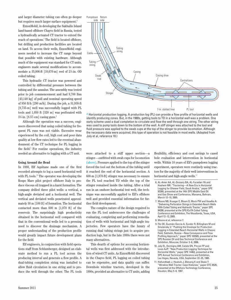
Elf engineers, in conjunction with field opera-tions staff from Schlumberger, designed an elab-orate method to run a PL tool across the producing interval and generate a flow profile. A dual-tubing completion string was installed to allow fluid circulation in one string and to pro-duce the well through the other. The PL tools
were attached to a stiff upper section—a stinger—outfitted with swab cups for locomotion (above). Pressure applied to the top of the stinger forced the tool out the bottom of the tubing until it reached the end of the horizontal section. A 600-m [1,970-ft] stinger was necessary to ensure the PL tool reached TD while the top of the stinger remained inside the tubing. After a trial run in an onshore horizontal test well, the tech-nique was successfully applied to Elf’s offshore well and provided essential information for fur-ther field development.
The complex nature of the design required to run the PL tool underscores the challenges of evaluating, completing and performing remedia-tion of wells with horizontal and high-angle tra-jectories. Few operators have the luxury of running dual tubing strings just to acquire pro-duction logs, but in the late 1980s there were not many alternatives.
This dearth of options for accessing horizon-tal wells was first addressed with the introduc-tion of wired CT units. As ExxonMobil discovered in the Chayvo field, PL logging on coiled tubing can be expensive, and data quality can suffer. Downhole wireline tractors, developed in the 1990s, provided an alternative to CT units, adding
flexibility, efficiency and cost savings to cased hole evaluation and intervention in horizontal wells. Within 10 years of Elf’s pumpdown logging experiment, operators were routinely using trac-tors for the majority of their well interventions in horizontal and high-angle wells.11
6. AL-Amer AA, AL-Dossary BA, AL-Furaidan YA and Hashem MK: “Tractoring—A New Era in Horizontal Logging for Ghawar Field, Saudi Arabia,” paper SPE 93260, presented at the 14th SPE Middle East Oil and Gas Show and Conference, Manama, Bahrain, March 12–15, 2005.
7. Moore NB, Krueger E, Bloom D, Mock PW and Veselka A: “Delivering Perforation Strings in Extended-Reach Wells With Coiled Tubing and Hydraulic Tractor,” paper SPE 94208, presented at the SPE/ICoTA Coiled Tubing Conference and Exhibition, The Woodlands, Texas, USA, April 12–13, 2005.
8. Moore et al, reference 7. 9. Fitz DE, Guzmán-Garcia A, Sunder R, Billingham M and
Smolensky V: “Pushing the Envelope for Production Logging in Extended Reach Horizontal Wells in Chayvo Field, Sakhalin, Russia—New Conveyance and Flow Profiling Approach,” paper SPE 103589, presented at the SPE Russian Oil and Gas Technical Conference and Exhibition, Moscow, October 3–6, 2006.
10. Joly EL, Dormigny AM, Catala GN, Pincon FP and Louis AJP: “New Production Logging Technique for Horizontal Wells,” paper SPE 14463, presented at the SPE Annual Technical Conference and Exhibition, Las Vegas, Nevada, USA, September 22–25, 1985.
11. Hallundbæk J, Haukvik J, Østvang K and Skeie T: “Wireline Well Tractor: Case Histories,” paper OTC 8535, presented at the Offshore Technology Conference, Houston, May 5–8, 1997.
> Horizontal production logging. A production log (PL) can provide a flow profile of horizontal wells and identify producing zones. But, in the 1980s, getting tools to TD in a horizontal well was a problem. One early scheme used a dual completion to circulate and flow the well through one string. The other string was used to pump tools down to the bottom of the well. A stiff stinger was attached to the tool and fluid pressure was applied to the swab cups at the top of the stinger to provide locomotion. Although the necessary data were acquired, this type of operation is not feasible in most wells. (Adapted from Joly et al, reference 10.)
Oilfield ReviewSUMMER 11 Conveyance Fig. 8ORSUM11-CONVY 8
Cable
Tubingstring
Tubingstring
Pumpdownside
Returnside
Swabcup
Stinger
CasingCasing shoe
Centralizers
7-in. slotted liner PL tool
41615schD5R1.indd 8 8/19/11 11:07 PM
26 Oilfield Review
Pulling a RopeAlthough earlier attempts were recorded, down-hole tractors successfully arrived in the oil field in the mid-1990s. In 1996, a device to access hori-zontal boreholes performed the first tractor ser-vice on a well in Norway.12 Developed to perform
well interventions without the high cost associ-ated with CT services, downhole tractors dramat-ically changed the way North Sea operators planned and managed their fields.13
Prior to 1996, interventions had been per-formed almost exclusively by CT units. By 2009,
approximately 80% of the interventions performed by one operator had shifted to wireline tractors.14 Not only did this reduce costs, it expanded both the frequency and scope of interventions.
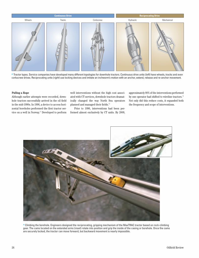
> Tractor types. Service companies have developed many different topologies for downhole tractors. Continuous drive units (left) have wheels, tracks and even corkscrew drives. Reciprocating units (right) use locking devices and imitate an inchworm’s motion with an anchor, extend, release and re-anchor movement.
Tracks Corkscrew MechanicalHydraulicWheels
Continuous Drive Reciprocating Drive
> Climbing the borehole. Engineers designed the reciprocating, gripping mechanism of the MaxTRAC tractor based on rock-climbing gear. The cams located on the extended arms (inset) rotate into position and grip the inside of the casing or borehole. Once the cams are securely locked, the tractor can move forward, but backward movement is nearly impossible.
Oilfield ReviewSUMMER 11 Conveyance Fig. 10ORSUM11-CONVY 10
41615schD5R1.indd 26 8/12/11 8:02 PM
Summer 2011 27
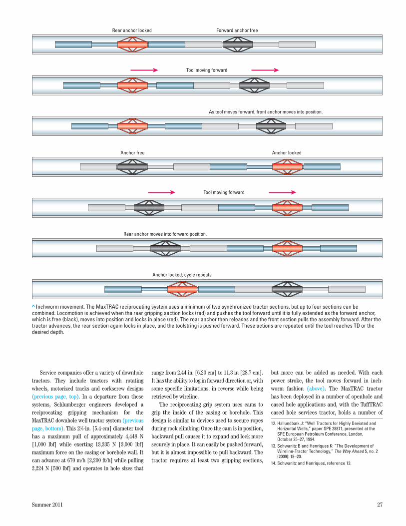
Service companies offer a variety of downhole tractors. They include tractors with rotating wheels, motorized tracks and corkscrew designs (previous page, top). In a departure from these systems, Schlumberger engineers developed a reciprocating gripping mechanism for the MaxTRAC downhole well tractor system (previous page, bottom). This 21/8-in. [5.4-cm] diameter tool has a maximum pull of approximately 4,448 N [1,000 lbf] while exerting 13,335 N [3,000 lbf] maximum force on the casing or borehole wall. It can advance at 670 m/h [2,200 ft/h] while pulling 2,224 N [500 lbf] and operates in hole sizes that
range from 2.44 in. [6.20 cm] to 11.3 in [28.7 cm]. It has the ability to log in forward direction or, with some specific limitations, in reverse while being retrieved by wireline.
The reciprocating grip system uses cams to grip the inside of the casing or borehole. This design is similar to devices used to secure ropes during rock climbing: Once the cam is in position, backward pull causes it to expand and lock more securely in place. It can easily be pushed forward, but it is almost impossible to pull backward. The tractor requires at least two gripping sections,
but more can be added as needed. With each power stroke, the tool moves forward in inch-worm fashion (above). The MaxTRAC tractor has been deployed in a number of openhole and cased hole applications and, with the TuffTRAC cased hole services tractor, holds a number of
12. Hallundbæk J: “Well Tractors for Highly Deviated and Horizontal Wells,” paper SPE 28871, presented at the SPE European Petroleum Conference, London, October 25–27, 1994.
13. Schwanitz B and Henriques K: “The Development of Wireline-Tractor Technology,” The Way Ahead 5, no. 2 (2009): 18–20.
14. Schwanitz and Henriques, reference 13.
> Inchworm movement. The MaxTRAC reciprocating system uses a minimum of two synchronized tractor sections, but up to four sections can be combined. Locomotion is achieved when the rear gripping section locks (red) and pushes the tool forward until it is fully extended as the forward anchor, which is free (black), moves into position and locks in place (red). The rear anchor then releases and the front section pulls the assembly forward. After the tractor advances, the rear section again locks in place, and the toolstring is pushed forward. These actions are repeated until the tool reaches TD or the desired depth.
Oilfield ReviewSUMMER 11 Conveyance Fig. 11ORSUM11-CONVY 11
Rear anchor locked
Anchor locked, cycle repeats
Anchor locked
Forward anchor free
Anchor free
Tool moving forward
As tool moves forward, front anchor moves into position.
Rear anchor moves into forward position.
Tool moving forward
41615schD5R1.indd 27 8/12/11 8:02 PM
28 Oilfield Review
operational records (above). Should the tool ever lose power, the arms with the gripping cams auto-matically return to a retracted position for ease of tool retrieval.
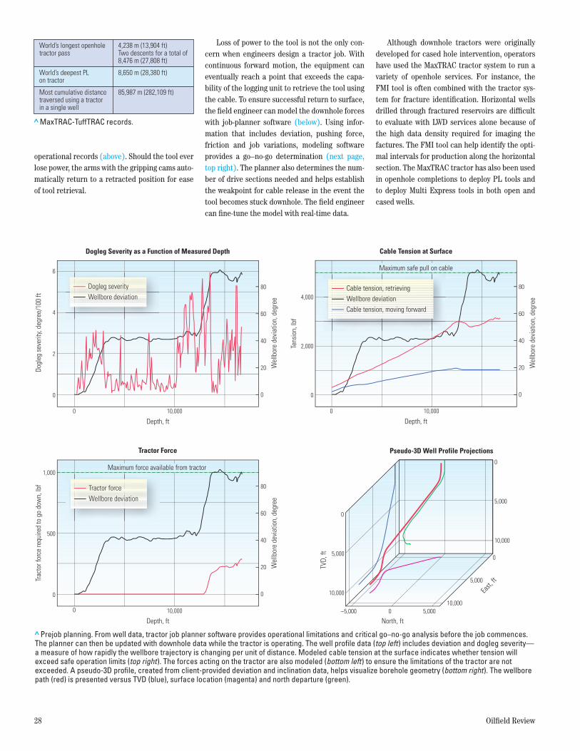
Loss of power to the tool is not the only con-cern when engineers design a tractor job. With continuous forward motion, the equipment can eventually reach a point that exceeds the capa-bility of the logging unit to retrieve the tool using the cable. To ensure successful return to surface, the field engineer can model the downhole forces with job-planner software (below). Using infor-mation that includes deviation, pushing force, friction and job variations, modeling software provides a go–no-go determination (next page, top right). The planner also determines the num-ber of drive sections needed and helps establish the weakpoint for cable release in the event the tool becomes stuck downhole. The field engineer can fine-tune the model with real-time data.
Although downhole tractors were originally developed for cased hole intervention, operators have used the MaxTRAC tractor system to run a variety of openhole services. For instance, the FMI tool is often combined with the tractor sys-tem for fracture identification. Horizontal wells drilled through fractured reservoirs are difficult to evaluate with LWD services alone because of the high data density required for imaging the factures. The FMI tool can help identify the opti-mal intervals for production along the horizontal section. The MaxTRAC tractor has also been used in openhole completions to deploy PL tools and to deploy Multi Express tools in both open and cased wells.
Oilfield ReviewSUMMER 11 Conveyance Fig. Table 2ORSUM11-CONVY Table 2
World’s longest openholetractor pass
4,238 m (13,904 ft)Two descents for a total of8,476 m (27,808 ft)
8,650 m (28,380 ft)
85,987 m (282,109 ft)
World’s deepest PL on tractor
Most cumulative distancetraversed using a tractor in a single well
> Prejob planning. From well data, tractor job planner software provides operational limitations and critical go–no-go analysis before the job commences. The planner can then be updated with downhole data while the tractor is operating. The well profile data (top left) includes deviation and dogleg severity— a measure of how rapidly the wellbore trajectory is changing per unit of distance. Modeled cable tension at the surface indicates whether tension will exceed safe operation limits (top right). The forces acting on the tractor are also modeled (bottom left) to ensure the limitations of the tractor are not exceeded. A pseudo-3D profile, created from client-provided deviation and inclination data, helps visualize borehole geometry (bottom right). The wellbore path (red) is presented versus TVD (blue), surface location (magenta) and north departure (green).
Oilfield ReviewSUMMER 11 Conveyance Fig. 12ORSUM11-CONVY 12
Dogl
eg s
ever
ity, d
egre
e/10
0 ft
Trac
tor f
orce
requ
ired
to g
o do
wn,
lbf
TVD,
ft
Wel
lbor
e de
viat
ion,
deg
ree
6
4
2
0
0
0
05,000
5,000
–5,000 0 5,000
10,000
0
5,000
10,000
10,000
500
1,000
0 10,000
0
20
40
60
80
Wel
lbor
e de
viat
ion,
deg
ree
0
20
40
60
80
Depth, ft
Dogleg Severity as a Function of Measured Depth
Tractor Force Pseudo-3D Well Profile Projections
0 10,000
Depth, ft North, ft
East,
ft
Tens
ion,
lbf
Wel
lbor
e de
viat
ion,
deg
ree
0 10,000
0
2,000
4,000
0
20
40
60
80
Cable Tension at Surface
Maximum safe pull on cable
Maximum force available from tractor
Depth, ft
Dogleg severityWellbore deviation
Tractor forceWellbore deviation
Cable tension, retrievingWellbore deviationCable tension, moving forward
>MaxTRAC-TuffTRAC records.
41615schD5R1.indd 28 8/22/11 12:19 PM
Summer 2011 29
Tackling a GiantSaudi Aramco has been instrumental in develop-ing tractor technology.15 For the Ghawar field, the largest onshore oil field in the world, engineers have increasingly turned to horizontal, extended-reach and multilateral wellbores as part of the ongoing development program. The expense of using CT units, as well as the difficulty of access-ing complex completion geometries for conveying diagnostic and surveillance tools, has led Aramco to investigate alternatives.16
Aramco, which extensively tested various downhole tractors, views them as an enabling technology for intervention services. The com-pany has determined that tractors can effectively log horizontal wells, far exceed the reach of con-ventional CT units, provide significant cost bene-fit and offer safer operations compared with complex CT mobilization and deployment.17
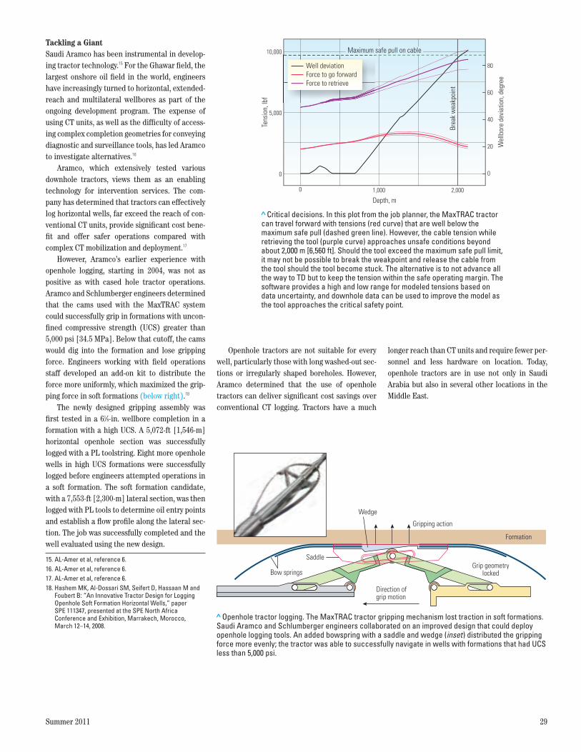
However, Aramco’s earlier experience with openhole logging, starting in 2004, was not as positive as with cased hole tractor operations. Aramco and Schlumberger engineers determined that the cams used with the MaxTRAC system could successfully grip in formations with uncon-fined compressive strength (UCS) greater than 5,000 psi [34.5 MPa]. Below that cutoff, the cams would dig into the formation and lose gripping force. Engineers working with field operations staff developed an add-on kit to distribute the force more uniformly, which maximized the grip-ping force in soft formations (below right).18
The newly designed gripping assembly was first tested in a 61/8-in. wellbore completion in a formation with a high UCS. A 5,072-ft [1,546-m] horizontal openhole section was successfully logged with a PL toolstring. Eight more openhole wells in high UCS formations were successfully logged before engineers attempted operations in a soft formation. The soft formation candidate, with a 7,553-ft [2,300-m] lateral section, was then logged with PL tools to determine oil entry points and establish a flow profile along the lateral sec-tion. The job was successfully completed and the well evaluated using the new design.
Openhole tractors are not suitable for every well, particularly those with long washed-out sec-tions or irregularly shaped boreholes. However, Aramco determined that the use of openhole tractors can deliver significant cost savings over conventional CT logging. Tractors have a much
longer reach than CT units and require fewer per-sonnel and less hardware on location. Today, openhole tractors are in use not only in Saudi Arabia but also in several other locations in the Middle East.
> Critical decisions. In this plot from the job planner, the MaxTRAC tractor can travel forward with tensions (red curve) that are well below the maximum safe pull (dashed green line). However, the cable tension while retrieving the tool (purple curve) approaches unsafe conditions beyond about 2,000 m [6,560 ft]. Should the tool exceed the maximum safe pull limit, it may not be possible to break the weakpoint and release the cable from the tool should the tool become stuck. The alternative is to not advance all the way to TD but to keep the tension within the safe operating margin. The software provides a high and low range for modeled tensions based on data uncertainty, and downhole data can be used to improve the model as the tool approaches the critical safety point.
Oilfield ReviewSUMMER 11 Conveyance Fig. 13ORSUM11-CONVY 13
Tens
ion,
lbf
0
5,000
10,000
Wel
lbor
e de
viat
ion,
deg
ree
0
20
40
60
80
0 1,000 2,000
Depth, m
Maximum safe pull on cable
Brea
k w
eakp
oint
Well deviationForce to go forwardForce to retrieve
> Openhole tractor logging. The MaxTRAC tractor gripping mechanism lost traction in soft formations. Saudi Aramco and Schlumberger engineers collaborated on an improved design that could deploy openhole logging tools. An added bowspring with a saddle and wedge (inset) distributed the gripping force more evenly; the tractor was able to successfully navigate in wells with formations that had UCS less than 5,000 psi.
Oilfield ReviewSUMMER 11 Conveyance Fig. 14ORSUM11-CONVY 14
Gripping action
Grip geometrylocked
Wedge
Formation
Saddle
Bow springs
Direction of grip motion
15. AL-Amer et al, reference 6.16. AL-Amer et al, reference 6.17. AL-Amer et al, reference 6.18. Hashem MK, Al-Dossari SM, Seifert D, Hassaan M and
Foubert B: “An Innovative Tractor Design for Logging Openhole Soft Formation Horizontal Wells,” paper SPE 111347, presented at the SPE North Africa Conference and Exhibition, Marrakech, Morocco, March 12–14, 2008.
41615schD5R1.indd 29 8/12/11 8:02 PM
30 Oilfield Review
When the Going Gets ToughLogging is not the only operation that takes place in horizontal wells. Initial completion operations often use drilling or workover rigs to run TCP guns, which can traverse extremely long inter-vals. However, after the rig has moved on, reme-dial perforating in horizontal wells can be difficult to perform. CT units are an option for this task but they have depth limitations. Tractor
tools have been used to run and position perfo-rating guns, but the shock that the downhole equipment can receive—up to 20,000 gn—can damage sensitive electronic and mechanical components.
Recognizing the need for a more robust trac-tor for perforating services, Schlumberger engi-neers designed the TuffTRAC cased hole services tractor. Tool movement is accomplished using
mechanically powered wheels (above). The TuffTRAC tool is bigger and stronger than the MaxTRAC tractor and has a much simpler design; it has minimal downhole electronics. Maximum running speed is 975 m/h [3,200 ft/h] and maxi-mum pulling force is 10,676 N [2,400 lbf]. It is designed primarily for perforating and cement evaluation. The TuffTRAC system also offers trac-tion control, which dynamically adjusts the grip-ping force while the tractor is in forward motion.
The TuffTRAC equipment is currently the only tractor qualified for perforating that can reverse out of the well. This has proved beneficial in hori-zontal well sections where guns were trapped by debris in the wellbore. On at least one occasion, surface-applied tension was not sufficient to free the guns because the high angle of the well pro-hibited pulling force from being transmitted to the tools. By moving in reverse, the tractor was able to free the guns, which were then retrieved without a costly fishing operation.
Although perforating can damage electronics and mechanical components, the TuffTRAC ser-vice has demonstrated that properly engineered solutions can mitigate some of the effects of high explosives (left). Tested to extreme limits, this new tractor design has been field qualified. In one North Sea well that had initially been com-
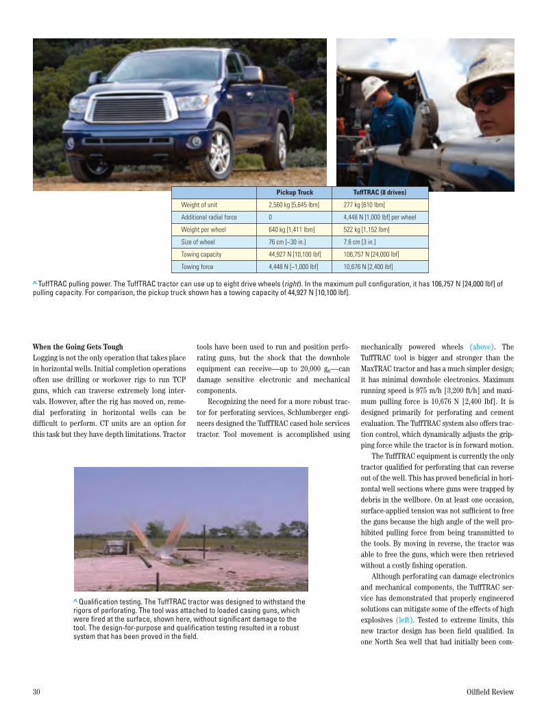
> TuffTRAC pulling power. The TuffTRAC tractor can use up to eight drive wheels (right). In the maximum pull configuration, it has 106,757 N [24,000 lbf] of pulling capacity. For comparison, the pickup truck shown has a towing capacity of 44,927 N [10,100 lbf].
Oilfield ReviewSUMMER 11 Conveyance Fig. 15ORSUM11-CONVY 15
Pickup Truck TuffTRAC (8 drives)
2,560 kg [5,645 lbm] 277 kg [610 lbm]Weight of unit
0 4,448 N [1,000 lbf] per wheelAdditional radial force
640 kg [1,411 lbm] 522 kg [1,152 lbm]Weight per wheel
76 cm [~30 in.] 7.6 cm [3 in.]Size of wheel
44,927 N [10,100 lbf] 106,757 N [24,000 lbf]Towing capacity
4,448 N [~1,000 lbf] 10,676 N [2,400 lbf]Towing force
> Qualification testing. The TuffTRAC tractor was designed to withstand the rigors of perforating. The tool was attached to loaded casing guns, which were fired at the surface, shown here, without significant damage to the tool. The design-for-purpose and qualification testing resulted in a robust system that has been proved in the field.
Oilfield ReviewSUMMER 11 Conveyance Fig. 16ORSUM11-CONVY 16
41615schD5R1.indd 30 8/12/11 8:02 PM
Summer 2011 31
pleted as a commingled oil producer from two separate zones, only water was being produced. Engineers ran the TuffTRAC system to set two plugs, ran 73.1 m [240 ft] of 27/8-in. high shot den-sity guns in four runs and made six trips to retro-fit sand screens. For this single intervention, the tractor traversed 22,500 m [73,819 ft] without incident. The procedures resulted in resumption of oil production without a costly workover and recompletion.
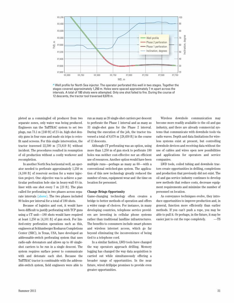
In another North Sea horizontal well, an oper-ator needed to perforate approximately 1,250 m [4,100 ft] of reservoir section for a water injec-tion project. One objective was to achieve a par-ticular perforation hole size in heavy-wall 65/8-in. liner with one shot every 7 m [23 ft]. The plan called for perforating in two phases across sepa-rate intervals (above). The two phases included 90 holes per interval for a total of 180 shots.
Because of logistics and cost, it would have been difficult to justify perforating with TCP guns using a CT unit—180 shots would have required at least 1,250 m [4,101 ft] of gun stock. For lim-ited-entry perforation operations such as this, engineers at Schlumberger Rosharon Completions Center (SRC), in Texas, USA, have developed an addressable-switch perforating system that uses radio-safe detonators and allows up to 40 single-shot carriers to be run in a single descent. The system requires surface power to communicate with and detonate each shot. Because the TuffTRAC tractor is combinable with the address-able-switch system, field engineers were able to
run as many as 20 single-shot carriers per descent to perforate the Phase 1 interval and as many as 33 single-shot guns for the Phase 2 interval. During the execution of the job, the tractor tra-versed a total of 8,670 m [28,450 ft] in the course of 12 descents.
Although CT perforating was an option, using more than 1,250 m of gun stock to perforate 180 holes was neither cost-effective nor an efficient use of resources. Another option would have been multiple runs—perhaps as many as 60—with a conventional switched-gun system. The applica-tion of this new technology greatly reduced the number of runs, equipment wear and the time on location for personnel.
Change Brings OpportunityGame-changing technology often creates a bridge to better methods of operation and offers a wider range of choices. For instance, in many developing countries, telephone service provid-ers are investing in cellular phone systems rather than traditional landline infrastructures. The benefits to consumers include smart phones and wireless internet access, which go far beyond eliminating the inconvenience of being tied to a telephone cord.
In a similar fashion, LWD tools have changed the way operators approach drilling. Memory logging has changed the way data acquisition is carried out while simultaneously offering a broader range of opportunities. In the near future, wired drillpipe promises to provide even greater opportunities.
Wireless downhole communication may become more readily available to the oil and gas industry, and there are already commercial sys-tems that communicate with downhole tools via radio waves. Depth and data limitations for wire-less systems exist at present, but controlling downhole devices and receiving data without the use of cables and wires open new possibilities and applications for operators and service companies.
LWD tools, coiled tubing and downhole trac-tors create opportunities in drilling, completions and production that previously did not exist. The oil and gas service industry continues to develop new methods that reduce costs, decrease equip-ment requirements and minimize the number of personnel on location.
As conveyance techniques evolve, they intro-duce opportunities to improve production and, in general, function more efficiently than earlier methods. If you can’t push a rope, you may be able to pull it. Or perhaps, in the future, it may be easier just to cut the rope completely. —TS
>Well profile for North Sea injector. The operator perforated this well in two stages. Together the stages covered approximately 1,250 m. Holes were spaced approximately 7 m apart across the intervals. A total of 180 shots were attempted. Only one shot failed to fire. During the course of 12 descents, the tractor tool traversed 8,670 m.
Oilfield ReviewSUMMER 11 Conveyance Fig. 17ORSUM11-CONVY 17
TVD,
m
MD, m
20
30
40
XX,400
XX,000 XX,250 XX,500 XX,750 XY,000 XY,250 XY,500 XY,750
XY,400
XX,600
XY,800
XY,600
XX,800
XY,000
XX,200
XY,200 50
60
70
80
90
100
Incl
inat
ion,
deg
ree
Well profilePhase 2 perforationPhase 1 perforationInclination, degrees
41615schD5R1.indd 31 8/12/11 8:02 PM


![Session(รวม) sum11[1]](https://img.pdfslide.net/doc/110x75/54663f8caf79595d038b4c49/session-sum111-5584ad576417a.jpg)


