Embed Size (px)
Citation preview
5
5
5P
5
5P
P
80
00
L
K
V
L
T
X
X
PO
CC
X4
XS
X6
X6
X8
X8
XH
XK
XK
X1
X3
GR
CS
XT
W
W
XC
XF
XD
EL
CT
FS
TR
AP
ID
Conveyor system X65ContentsS
System information...........................................................111Chains X65 ........................................................................112Chain accessories X65 ......................................................114Beams X65 ........................................................................114Beam accessories X65 ......................................................115Tools for conveyor beam...................................................116Slide rails X65 ...................................................................116Slide rails X65, hardened steel ..........................................117Drive and idler units – introduction ...................................119End drive units X65 Type H, direct drive, with slip clutch..120End drive units X65 Type C, direct drive, no slip clutch.....120End drive units X65 Type M, direct drive, no slip clutch....121End drive units X65 Type H, direct drive, no slip clutch ....121Drive units for wedge conveyors .......................................122End drive units X65, suspended, slip clutch......................123Double drive units X65, direct drive ..................................124Intermediate drive units X65, direct drive..........................125Horizontal bend drive unit X65 ..........................................126
Synchronous drive unit X65 ..............................................126Idler units X65...................................................................127X-bends.............................................................................128Components for wedge track width adjustment ................129Wheel bends X65 ..............................................................130Wheel cover for Wheel bend with no return chain.............130Plain bends X65 ................................................................131Support rail for plain bends X65........................................132Vertical bends X65 ............................................................132Angle plates X65 ...............................................................134Front piece X65 .................................................................135Drip trays & drip pans – introduction................................136Drip trays X65 ...................................................................137Drip catchers X65..............................................................138Drip pans X65 ...................................................................138Guide rail system...............................................................140Conveyor support..............................................................140
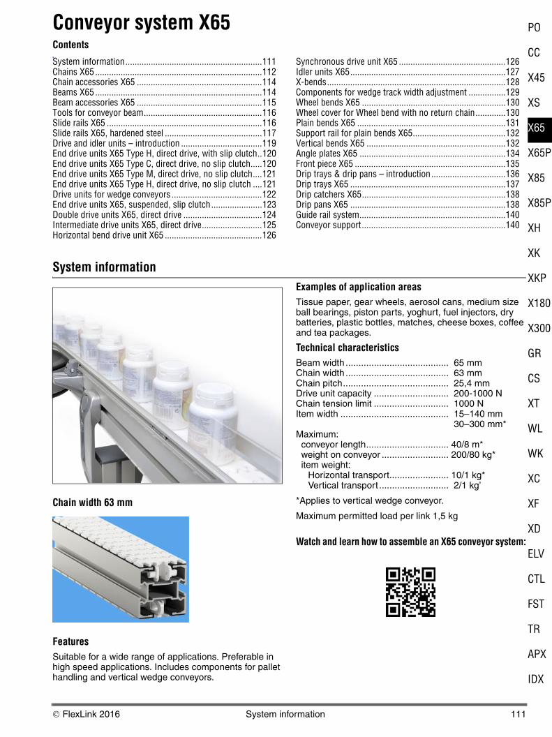
System information
Chain width 63 mm
Features Suitable for a wide range of applications. Preferable in high speed applications. Includes components for pallet handling and vertical wedge conveyors.
Examples of application areas Tissue paper, gear wheels, aerosol cans, medium size ball bearings, piston parts, yoghurt, fuel injectors, dry batteries, plastic bottles, matches, cheese boxes, coffee and tea packages.
Technical characteristicsBeam width ........................................ 65 mmChain width ........................................ 63 mmChain pitch......................................... 25,4 mmDrive unit capacity ............................. 200-1000 NChain tension limit ............................. 1000 NItem width .......................................... 15–140 mm
30–300 mm*Maximum:
conveyor length................................ 40/8 m*weight on conveyor .......................... 200/80 kg*item weight: Horizontal transport....................... 10/1 kg* Vertical transport ........................... 2/1 kg’
*Applies to vertical wedge conveyor.
Maximum permitted load per link 1,5 kg
Watch and learn how to assemble an X65 conveyor system:
© FlexLink 2016 System information 111
Chains X65
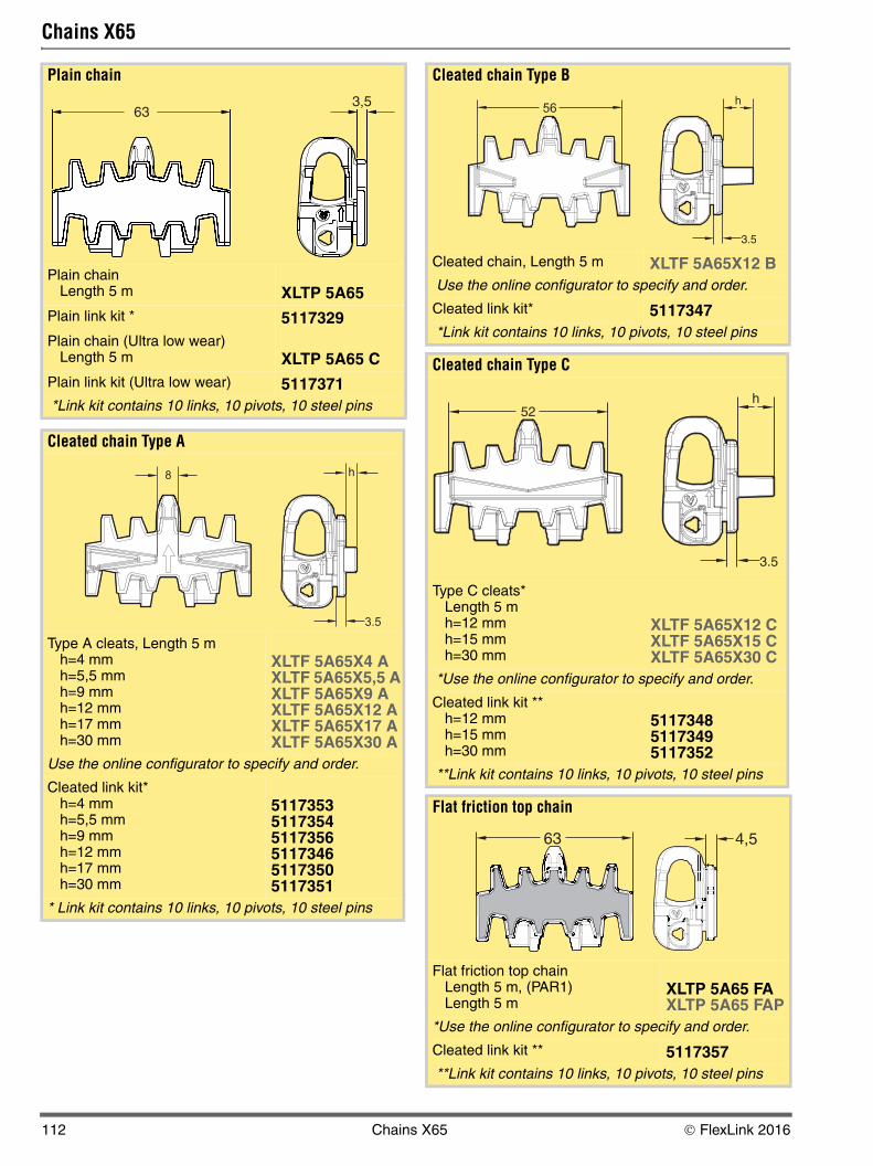
Plain chain
Plain chainLength 5 m XLTP 5A65
Plain link kit * 5117329Plain chain (Ultra low wear)
Length 5 m XLTP 5A65 CPlain link kit (Ultra low wear) 5117371 *Link kit contains 10 links, 10 pivots, 10 steel pins
Cleated chain Type A
Type A cleats, Length 5 mh=4 mmh=5,5 mmh=9 mmh=12 mmh=17 mmh=30 mm
XLTF 5A65X4 AXLTF 5A65X5,5 AXLTF 5A65X9 AXLTF 5A65X12 AXLTF 5A65X17 AXLTF 5A65X30 A
Use the online configurator to specify and order.
Cleated link kit*h=4 mmh=5,5 mmh=9 mmh=12 mmh=17 mmh=30 mm
511735351173545117356511734651173505117351
* Link kit contains 10 links, 10 pivots, 10 steel pins
633,5
Cleated chain Type B
Cleated chain, Length 5 m XLTF 5A65X12 B Use the online configurator to specify and order.
Cleated link kit* 5117347 *Link kit contains 10 links, 10 pivots, 10 steel pins
Cleated chain Type C
Type C cleats*Length 5 mh=12 mmh=15 mmh=30 mm
XLTF 5A65X12 CXLTF 5A65X15 CXLTF 5A65X30 C
*Use the online configurator to specify and order.
Cleated link kit **h=12 mmh=15 mmh=30 mm
511734851173495117352
**Link kit contains 10 links, 10 pivots, 10 steel pins
Flat friction top chain
Flat friction top chainLength 5 m, (PAR1)Length 5 m
XLTP 5A65 FAXLTP 5A65 FAP
*Use the online configurator to specify and order.
Cleated link kit ** 5117357 **Link kit contains 10 links, 10 pivots, 10 steel pins
56
4,563
112 Chains X65 © FlexLink 2016
5
5
5P
5
5P
P
80
00
L
K
V
L
T
X
X
PO
CC
X4
XS
X6
X6
X8
X8
XH
XK
XK
X1
X3
GR
CS
XT
W
W
XC
XF
XD
EL
CT
FS
TR
AP
ID
Chains X65 (continued)
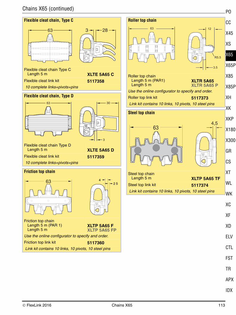
Flexible cleat chain, Type C
Flexible cleat chain Type CLength 5 m XLTE 5A65 C
Flexible cleat link kit 5117358 10 complete links+pivots+pins
Flexible cleat chain, Type D
Flexible cleat chain Type DLength 5 m XLTE 5A65 D
Flexible cleat link kit 5117359 10 complete links+pivots+pins
Friction top chain
Friction top chainLength 5 m (PAR 1)Length 5 m
XLTP 5A65 FXLTP 5A65 FP
Use the online configurator to specify and order.
Friction top link kit 5117360 Link kit contains 10 links, 10 pivots, 10 steel pins
63 3 28
30
3
63
63
Roller top chain
Roller top chainLength 5 m (PAR1)Length 5 m
XLTR 5A65XLTR 5A65 P
Use the online configurator to specify and order.
Roller top link kit 5117373 Link kit contains 10 links, 10 pivots, 10 steel pins
Steel top chain
Steel top chainLength 5 m XLTP 5A65 TF
Steel top link kit 5117374 Link kit contains 10 links, 10 pivots, 10 steel pins
634,5
© FlexLink 2016 Chains X65 113
Chain accessories X65
Beams X65
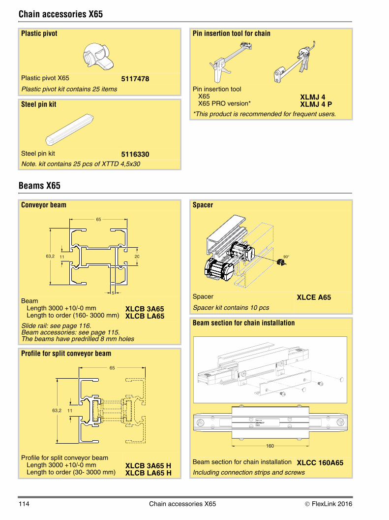
Plastic pivot
Plastic pivot X65 5117478Plastic pivot kit contains 25 items
Steel pin kit
Steel pin kit 5116330Note. kit contains 25 pcs of XTTD 4,5x30
Pin insertion tool for chain
Pin insertion tool X65X65 PRO version*
XLMJ 4XLMJ 4 P
*This product is recommended for frequent users.
X65MJ 4
Conveyor beam
BeamLength 3000 +10/-0 mmLength to order (160- 3000 mm)
XLCB 3A65XLCB LA65
Slide rail: see page 116.Beam accessories: see page 115. The beams have predrilled 8 mm holes
Profile for split conveyor beam
Profile for split conveyor beamLength 3000 +10/-0 mmLength to order (30- 3000 mm)
XLCB 3A65 HXLCB LA65 H
63,2 11
65
5
20
63,2 11
65
Spacer
Spacer XLCE A65Spacer kit contains 10 pcs
Beam section for chain installation
Beam section for chain installation XLCC 160A65Including connection strips and screws
5116103
90°
160
114 Chain accessories X65 © FlexLink 2016
5
5
5P
5
5P
P
80
00
L
K
V
L
T
X
X
PO
CC
X4
XS
X6
X6
X8
X8
XH
XK
XK
X1
X3
GR
CS
XT
W
W
XC
XF
XD
EL
CT
FS
TR
AP
ID
Beam accessories X65
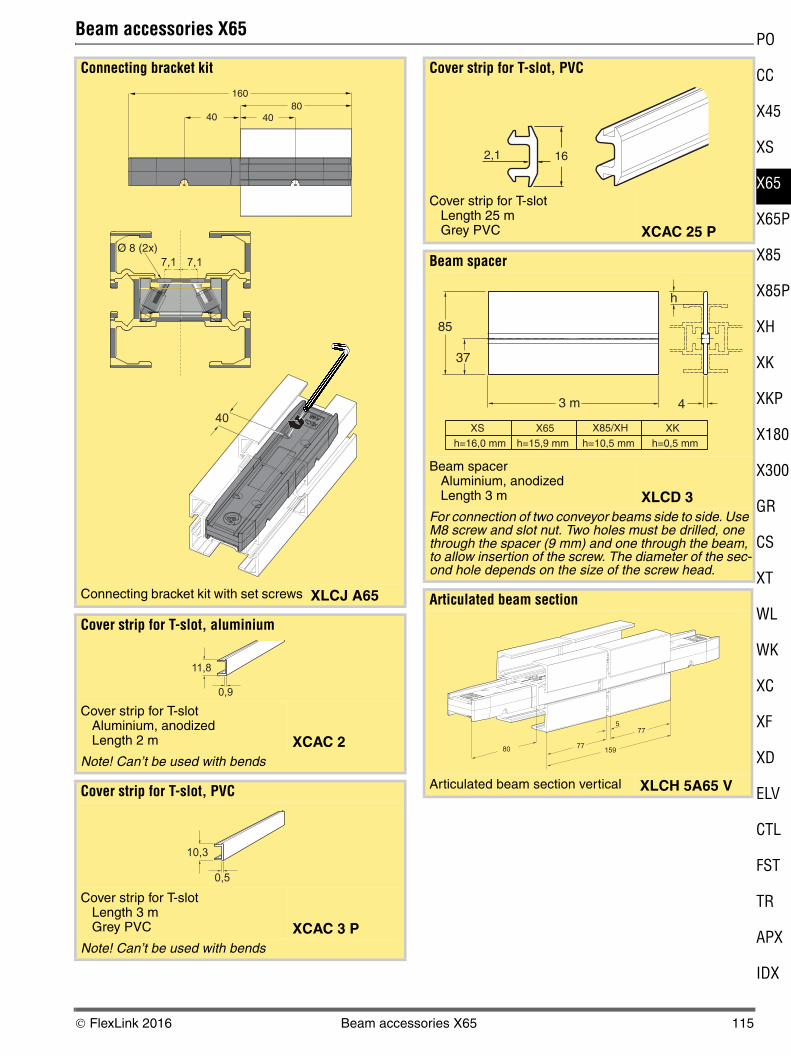
Connecting bracket kit
Connecting bracket kit with set screws XLCJ A65
Cover strip for T-slot, aluminium
Cover strip for T-slotAluminium, anodizedLength 2 m XCAC 2
Note! Can’t be used with bends
Cover strip for T-slot, PVC
Cover strip for T-slotLength 3 mGrey PVC XCAC 3 P
Note! Can’t be used with bends
160
404080
40
7,1 7,1
Ø 8 (2x)
0,9
11,8
0,5
10,3
Cover strip for T-slot, PVC
Cover strip for T-slotLength 25 mGrey PVC XCAC 25 P
Beam spacer
Beam spacerAluminium, anodizedLength 3 m XLCD 3
For connection of two conveyor beams side to side. Use M8 screw and slot nut. Two holes must be drilled, one through the spacer (9 mm) and one through the beam, to allow insertion of the screw. The diameter of the sec-ond hole depends on the size of the screw head.
Articulated beam section
Articulated beam section vertical XLCH 5A65 V
162,1
37
85
3 m 4
h
X65XS X85/XH XK
h=15,9 mmh=16,0 mm h=10,5 mm h=0,5 mm
77
77
159
5
80
© FlexLink 2016 Beam accessories X65 115
Tools for conveyor beam
Slide rails X65
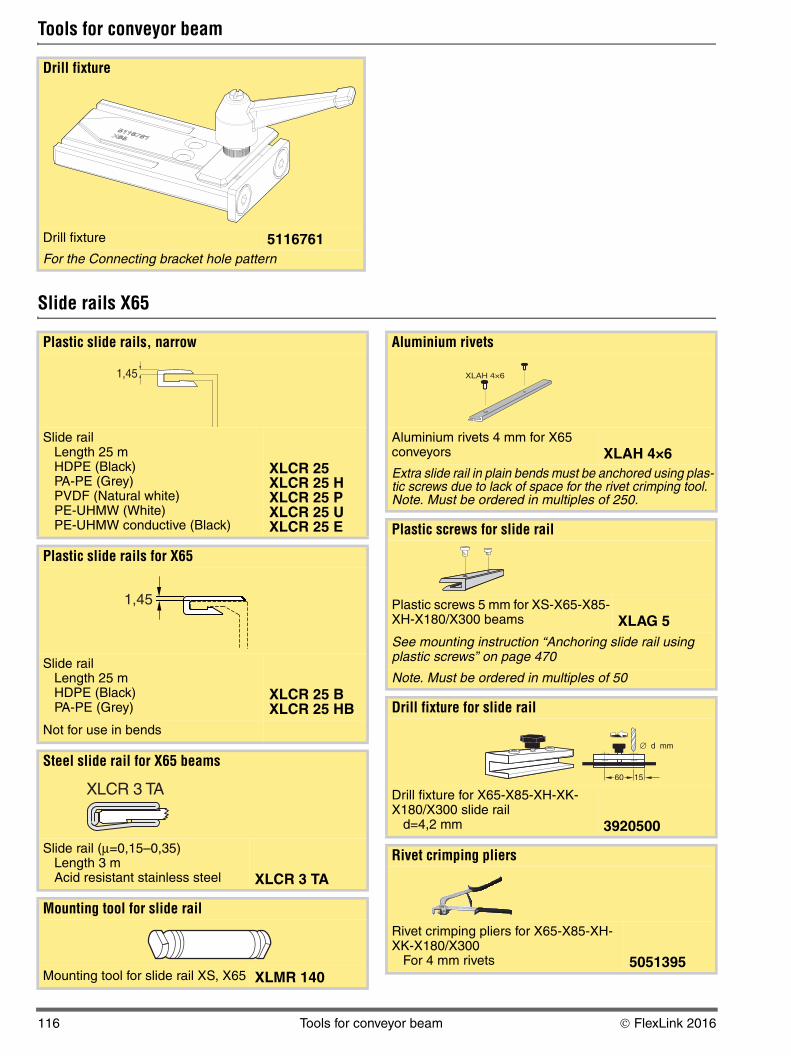
Drill fixture
Drill fixture 5116761For the Connecting bracket hole pattern
Plastic slide rails, narrow
Slide railLength 25 mHDPE (Black)PA-PE (Grey)PVDF (Natural white)PE-UHMW (White)PE-UHMW conductive (Black)
XLCR 25XLCR 25 HXLCR 25 PXLCR 25 UXLCR 25 E
Plastic slide rails for X65
Slide railLength 25 mHDPE (Black)PA-PE (Grey)
XLCR 25 BXLCR 25 HB
Not for use in bends
Steel slide rail for X65 beams
Slide rail (μ=0,15–0,35)Length 3 mAcid resistant stainless steel XLCR 3 TA
Mounting tool for slide rail
Mounting tool for slide rail XS, X65 XLMR 140
1,45
1,45
XLCR 3 TA
Aluminium rivets
Aluminium rivets 4 mm for X65 conveyors XLAH 4×6Extra slide rail in plain bends must be anchored using plas-tic screws due to lack of space for the rivet crimping tool. Note. Must be ordered in multiples of 250.
Plastic screws for slide rail
Plastic screws 5 mm for XS-X65-X85-XH-X180/X300 beams XLAG 5See mounting instruction “Anchoring slide rail using plastic screws” on page 470
Note. Must be ordered in multiples of 50
Drill fixture for slide rail
Drill fixture for X65-X85-XH-XK-X180/X300 slide rail
d=4,2 mm 3920500
Rivet crimping pliers
Rivet crimping pliers for X65-X85-XH-XK-X180/X300
For 4 mm rivets 5051395
XLAH 4×6
d mm∅
1560
116 Tools for conveyor beam © FlexLink 2016
5
5
5P
5
5P
P
80
00
L
K
V
L
T
X
X
PO
CC
X4
XS
X6
X6
X8
X8
XH
XK
XK
X1
X3
GR
CS
XT
W
W
XC
XF
XD
EL
CT
FS
TR
AP
ID
Slide rails X65 (continued)
Slide rails X65, hardened steel
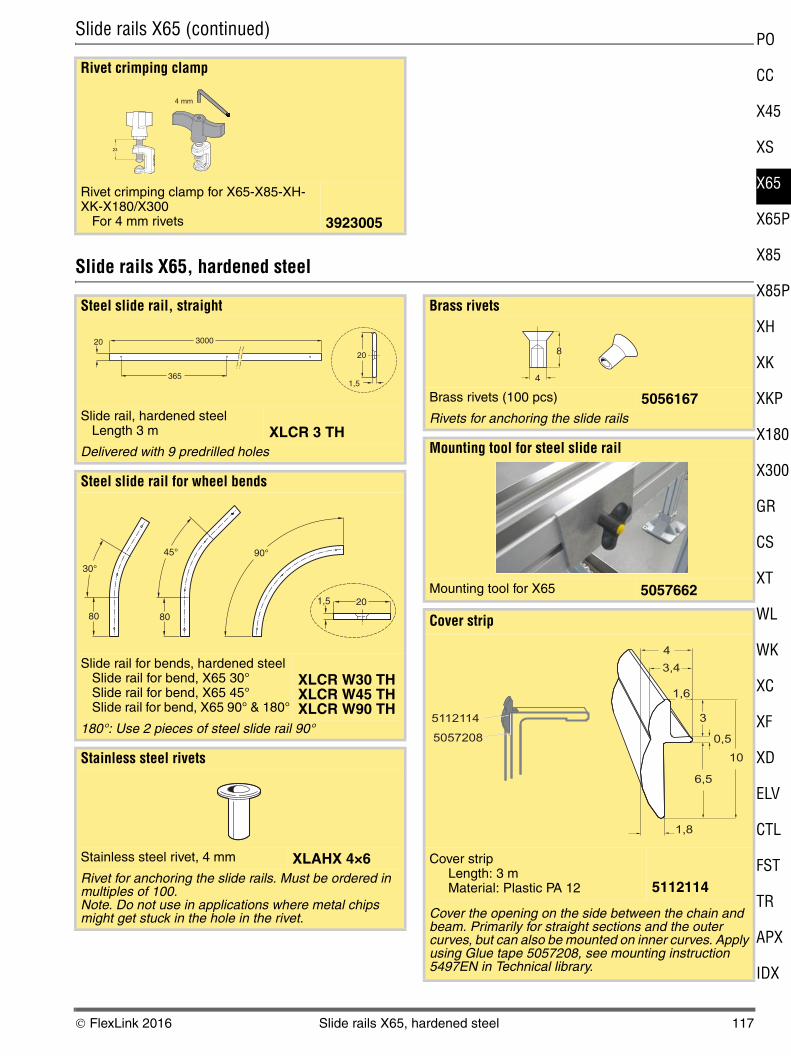
Rivet crimping clamp
Rivet crimping clamp for X65-X85-XH-XK-X180/X300
For 4 mm rivets 3923005
23
4 mm
Steel slide rail, straight
Slide rail, hardened steelLength 3 m XLCR 3 TH
Delivered with 9 predrilled holes
Steel slide rail for wheel bends
Slide rail for bends, hardened steelSlide rail for bend, X65 30°Slide rail for bend, X65 45°Slide rail for bend, X65 90° & 180°
XLCR W30 THXLCR W45 THXLCR W90 TH
180°: Use 2 pieces of steel slide rail 90°
Stainless steel rivets
Stainless steel rivet, 4 mm XLAHX 4×6Rivet for anchoring the slide rails. Must be ordered in multiples of 100. Note. Do not use in applications where metal chips might get stuck in the hole in the rivet.
20 3000
365
20
1,5
30°
80
1,5 20
45°
80
90°
Brass rivets
Brass rivets (100 pcs) 5056167Rivets for anchoring the slide rails
Mounting tool for steel slide rail
Mounting tool for X65 5057662
Cover strip
Cover stripLength: 3 mMaterial: Plastic PA 12 5112114
Cover the opening on the side between the chain and beam. Primarily for straight sections and the outer curves, but can also be mounted on inner curves. Apply using Glue tape 5057208, see mounting instruction 5497EN in Technical library.
8
4
10
0,5
6,5
3
1,8
1,6
3,4
4
5112114
5057208
© FlexLink 2016 Slide rails X65, hardened steel 117
Slide rails X65, hardened steel (continued)
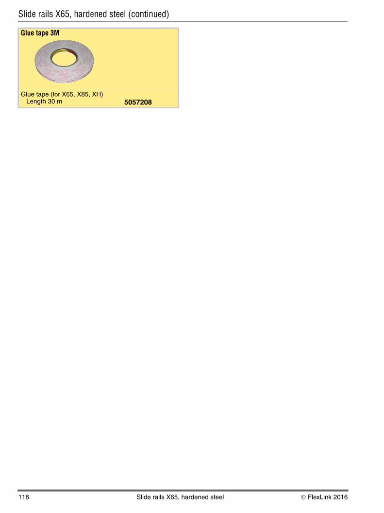
Glue tape 3M
Glue tape (for X65, X85, XH)Length 30 m 5057208
118 Slide rails X65, hardened steel © FlexLink 2016
5
5
5P
5
5P
P
80
00
L
K
V
L
T
X
X
PO
CC
X4
XS
X6
X6
X8
X8
XH
XK
XK
X1
X3
GR
CS
XT
W
W
XC
XF
XD
EL
CT
FS
TR
AP
ID
Drive and idler units – introduction
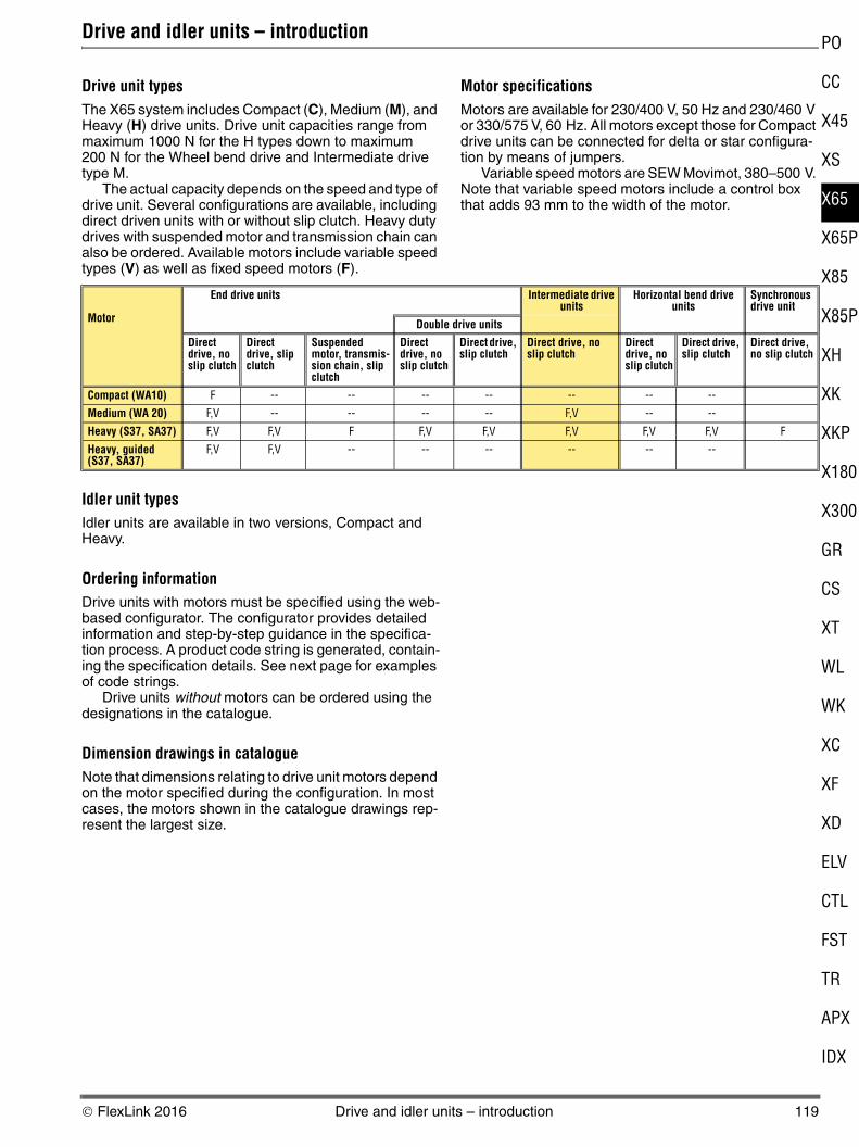
Drive unit typesThe X65 system includes Compact (C), Medium (M), and Heavy (H) drive units. Drive unit capacities range from maximum 1000 N for the H types down to maximum 200 N for the Wheel bend drive and Intermediate drive type M.
The actual capacity depends on the speed and type of drive unit. Several configurations are available, including direct driven units with or without slip clutch. Heavy duty drives with suspended motor and transmission chain can also be ordered. Available motors include variable speed types (V) as well as fixed speed motors (F).
Motor specificationsMotors are available for 230/400 V, 50 Hz and 230/460 V or 330/575 V, 60 Hz. All motors except those for Compact drive units can be connected for delta or star configura-tion by means of jumpers.
Variable speed motors are SEW Movimot, 380–500 V. Note that variable speed motors include a control box that adds 93 mm to the width of the motor.
Idler unit typesIdler units are available in two versions, Compact and Heavy.
Ordering informationDrive units with motors must be specified using the web-based configurator. The configurator provides detailed information and step-by-step guidance in the specifica-tion process. A product code string is generated, contain-ing the specification details. See next page for examples of code strings.
Drive units without motors can be ordered using the designations in the catalogue.
Dimension drawings in catalogueNote that dimensions relating to drive unit motors depend on the motor specified during the configuration. In most cases, the motors shown in the catalogue drawings rep-resent the largest size.
Motor
End drive units Intermediate drive units
Horizontal bend drive units
Synchronous drive unit
Double drive units
Direct drive, no slip clutch
Direct drive, slip clutch
Suspended motor, transmis-sion chain, slip clutch
Direct drive, no slip clutch
Direct drive, slip clutch
Direct drive, no slip clutch
Direct drive, no slip clutch
Direct drive, slip clutch
Direct drive, no slip clutch
Compact (WA10) F -- -- -- -- -- -- --
Medium (WA 20) F,V -- -- -- -- F,V -- --
Heavy (S37, SA37) F,V F,V F F,V F,V F,V F,V F,V F
Heavy, guided (S37, SA37)
F,V F,V -- -- -- -- -- --
© FlexLink 2016 Drive and idler units – introduction 119
End drive units X65 Type H, direct drive, with slip clutch
End drive units X65 Type C, direct drive, no slip clutch
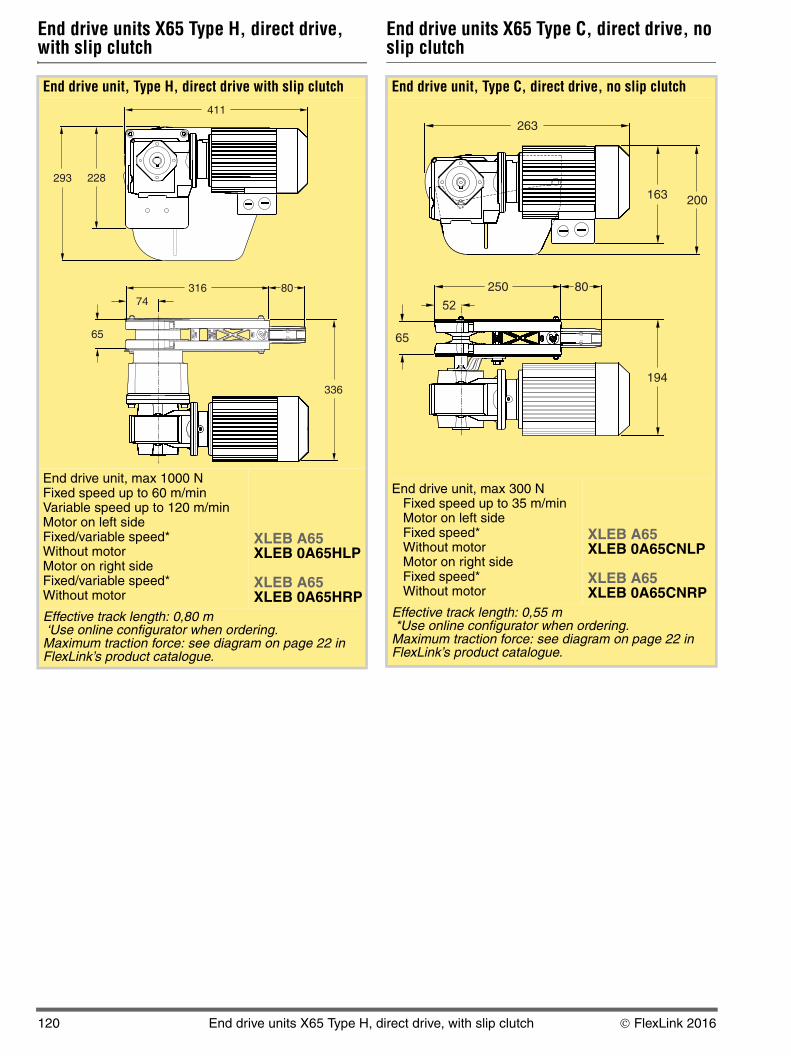
End drive unit, Type H, direct drive with slip clutch
End drive unit, max 1000 NFixed speed up to 60 m/minVariable speed up to 120 m/minMotor on left sideFixed/variable speed*Without motorMotor on right sideFixed/variable speed*Without motor
XLEB A65XLEB 0A65HLP
XLEB A65XLEB 0A65HRP
Effective track length: 0,80 m ‘Use online configurator when ordering.Maximum traction force: see diagram on page 22 in FlexLink’s product catalogue.
411
228
80316
65
336
74
293
End drive unit, Type C, direct drive, no slip clutch
End drive unit, max 300 NFixed speed up to 35 m/minMotor on left sideFixed speed*Without motorMotor on right sideFixed speed*Without motor
XLEB A65XLEB 0A65CNLP
XLEB A65XLEB 0A65CNRP
Effective track length: 0,55 m *Use online configurator when ordering.Maximum traction force: see diagram on page 22 in FlexLink’s product catalogue.
263
80250
65
194
163 200
52
120 End drive units X65 Type H, direct drive, with slip clutch © FlexLink 2016
5
5
5P
5
5P
P
80
00
L
K
V
L
T
X
X
PO
CC
X4
XS
X6
X6
X8
X8
XH
XK
XK
X1
X3
GR
CS
XT
W
W
XC
XF
XD
EL
CT
FS
TR
AP
ID
End drive units X65 Type M, direct drive, no slip clutch
End drive units X65 Type H, direct drive, no slip clutch
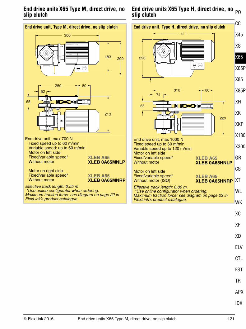
End drive unit, Type M, direct drive, no slip clutch
End drive unit, max 700 NFixed speed up to 60 m/minVariable speed: up to 60 m/minMotor on left sideFixed/variable speed*Without motor
Motor on right sideFixed/variable speed*Without motor
XLEB A65XLEB 0A65MNLP
XLEB A65XLEB 0A65MNRP
Effective track length: 0,55 m *Use online configurator when ordering.Maximum traction force: see diagram on page 22 in FlexLink’s product catalogue.
300
80250
65
213
183 200
52
End drive unit, Type H, direct drive, no slip clutch
End drive unit, max 1000 NFixed speed up to 60 m/minVariable speed up to 120 m/minMotor on left sideFixed/variable speed*Without motor
Motor on left sideFixed/variable speed*Without motor (ISO)
XLEB A65XLEB 0A65HNLP
XLEB A65XLEB 0A65HNRP
Effective track length: 0,80 m. *Use online configurator when ordering.Maximum traction force: see diagram on page 22 in FlexLink’s product catalogue.
411
80316
65
229
74
293
© FlexLink 2016 End drive units X65 Type M, direct drive, no slip clutch 121
Drive units for wedge conveyors
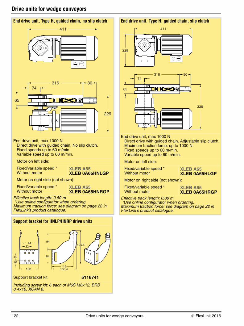
End drive unit, Type H, guided chain, no slip clutch
End drive unit, max 1000 NDirect drive with guided chain. No slip clutch.Fixed speeds up to 60 m/min.Variable speed up to 60 m/min.
Motor on left side:
Fixed/variable speed *Without motor
XLEB A65XLEB 0A65HNLGP
Motor on right side (not shown):
Fixed/variable speed *Without motor
XLEB A65XLEB 0A65HNRGP
Effective track length: 0,80 m *Use online configurator when ordering.Maximum traction force: see diagram on page 22 in FlexLink’s product catalogue.
Support bracket for HNLP/HNRP drive units
Support bracket kit 5116741
Including screw kit: 6 each of M6S M8×12, BRB 8,4×16, XCAN 8.
411
80316
65
229
74
44
44
22
102
195,5
135,4
84
94
20
118
End drive unit, Type H, guided chain, slip clutch
End drive unit, max 1000 NDirect drive with guided chain. Adjustable slip clutch.Maximum traction force: up to 1000 N.Fixed speeds up to 60 m/min.Variable speed up to 60 m/min.
Motor on left side:
Fixed/variable speed *Without motor
XLEB A65XLEB 0A65HLGP
Motor on right side (not shown):
Fixed/variable speed *Without motor
XLEB A65XLEB 0A65HRGP
Effective track length: 0,80 m *Use online configurator when ordering.Maximum traction force: see diagram on page 22 in FlexLink’s product catalogue.
411
80316
65
336
74
228
122 Drive units for wedge conveyors © FlexLink 2016
5
5
5P
5
5P
P
80
00
L
K
V
L
T
X
X
PO
CC
X4
XS
X6
X6
X8
X8
XH
XK
XK
X1
X3
GR
CS
XT
W
W
XC
XF
XD
EL
CT
FS
TR
AP
ID
End drive units X65, suspended, slip clutch
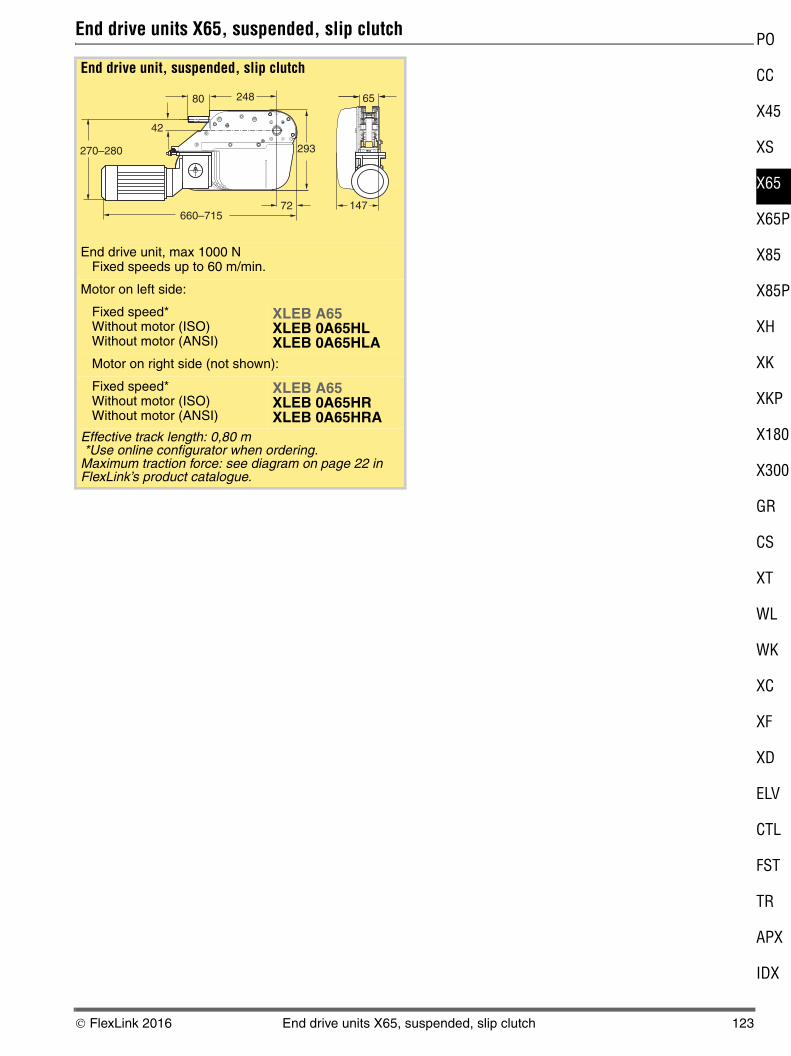
End drive unit, suspended, slip clutch
End drive unit, max 1000 NFixed speeds up to 60 m/min.
Motor on left side:
Fixed speed*Without motor (ISO)Without motor (ANSI)
XLEB A65XLEB 0A65HLXLEB 0A65HLA
Motor on right side (not shown):
Fixed speed*Without motor (ISO)Without motor (ANSI)
XLEB A65XLEB 0A65HRXLEB 0A65HRA
Effective track length: 0,80 m *Use online configurator when ordering.Maximum traction force: see diagram on page 22 in FlexLink’s product catalogue.
660–715
270–280
80
42
293
72
65
147
248
© FlexLink 2016 End drive units X65, suspended, slip clutch 123
Double drive units X65, direct drive
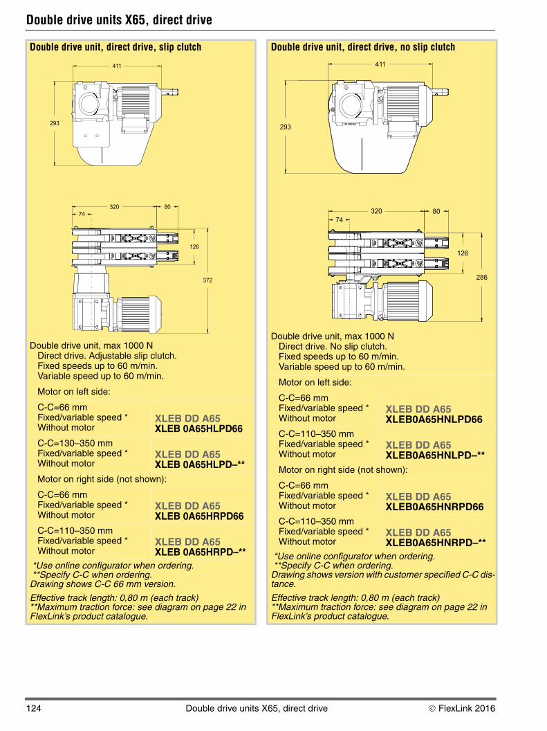
Double drive unit, direct drive, slip clutch
Double drive unit, max 1000 NDirect drive. Adjustable slip clutch.Fixed speeds up to 60 m/min.Variable speed up to 60 m/min.
Motor on left side:
C-C=66 mmFixed/variable speed *Without motor
XLEB DD A65XLEB 0A65HLPD66
C-C=130–350 mmFixed/variable speed *Without motor
XLEB DD A65XLEB 0A65HLPD–**
Motor on right side (not shown):
C-C=66 mmFixed/variable speed *Without motor
XLEB DD A65XLEB 0A65HRPD66
C-C=110–350 mmFixed/variable speed *Without motor
XLEB DD A65XLEB 0A65HRPD–**
*Use online configurator when ordering. **Specify C-C when ordering.Drawing shows C-C 66 mm version.
Effective track length: 0,80 m (each track)**Maximum traction force: see diagram on page 22 in FlexLink’s product catalogue.
74
411
293
372
126
80320
Double drive unit, direct drive, no slip clutch
Double drive unit, max 1000 NDirect drive. No slip clutch. Fixed speeds up to 60 m/min.Variable speed up to 60 m/min.
Motor on left side:
C-C=66 mmFixed/variable speed *Without motor
XLEB DD A65XLEB0A65HNLPD66
C-C=110–350 mmFixed/variable speed *Without motor
XLEB DD A65XLEB0A65HNLPD–**
Motor on right side (not shown):
C-C=66 mmFixed/variable speed *Without motor
XLEB DD A65XLEB0A65HNRPD66
C-C=110–350 mmFixed/variable speed *Without motor
XLEB DD A65XLEB0A65HNRPD–**
*Use online configurator when ordering. **Specify C-C when ordering.Drawing shows version with customer specified C-C dis-tance.
Effective track length: 0,80 m (each track)**Maximum traction force: see diagram on page 22 in FlexLink’s product catalogue.
411
293
320 80
74
126
286
124 Double drive units X65, direct drive © FlexLink 2016
5
5
5P
5
5P
P
80
00
L
K
V
L
T
X
X
PO
CC
X4
XS
X6
X6
X8
X8
XH
XK
XK
X1
X3
GR
CS
XT
W
W
XC
XF
XD
EL
CT
FS
TR
AP
ID
Intermediate drive units X65, direct drive
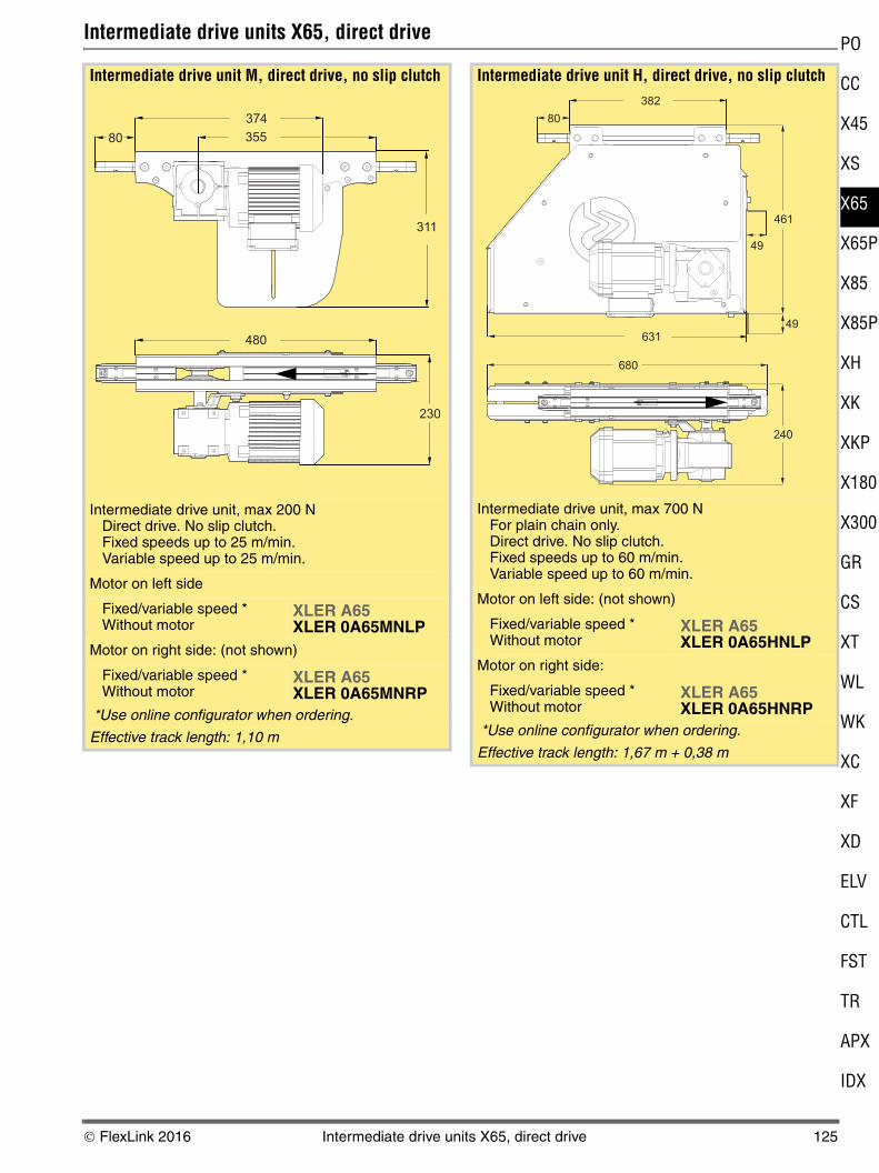
Intermediate drive unit M, direct drive, no slip clutch
Intermediate drive unit, max 200 NDirect drive. No slip clutch.Fixed speeds up to 25 m/min.Variable speed up to 25 m/min.
Motor on left side
Fixed/variable speed *Without motor
XLER A65XLER 0A65MNLP
Motor on right side: (not shown)
Fixed/variable speed *Without motor
XLER A65XLER 0A65MNRP
*Use online configurator when ordering.
Effective track length: 1,10 m
480
230
311
355
374
80
Intermediate drive unit H, direct drive, no slip clutch
Intermediate drive unit, max 700 NFor plain chain only.Direct drive. No slip clutch.Fixed speeds up to 60 m/min.Variable speed up to 60 m/min.
Motor on left side: (not shown)
Fixed/variable speed *Without motor
XLER A65XLER 0A65HNLP
Motor on right side:
Fixed/variable speed *Without motor
XLER A65XLER 0A65HNRP
*Use online configurator when ordering.
Effective track length: 1,67 m + 0,38 m
680
49
461
382
80
240
49
631
© FlexLink 2016 Intermediate drive units X65, direct drive 125
Horizontal bend drive unit X65
Synchronous drive unit X65
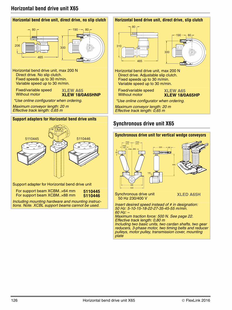
Horizontal bend drive unit, direct drive, no slip clutch
Horizontal bend drive unit, max 200 NDirect drive. No slip clutch.Fixed speeds up to 30 m/min.Variable speed up to 30 m/min.
Fixed/variable speed Without motor
XLEW A65XLEW 18/0A65HNP
*Use online configurator when ordering.
Maximum conveyor length: 20 mEffective track length: 0,65 m
Support adapters for Horizontal bend drive units
Support adapter for Horizontal bend drive unit
For support beam XCBM..×64 mmFor support beam XCBM..×88 mm
51104455110446
Including mounting hardware and mounting instruc-tions. Note. XCBL support beams cannot be used.
300
80 80190
465
206
51104465110445
Horizontal bend drive unit, direct drive, slip clutch
Horizontal bend drive unit, max 200 NDirect drive. Adjustable slip clutch.Fixed speeds up to 30 m/min.Variable speed up to 30 m/min.
Fixed/variable speed Without motor
XLEW A65XLEW 18/0A65HP
*Use online configurator when ordering.
Maximum conveyor length: 20 mEffective track length: 0,65 m
Synchronous drive unit for vertical wedge conveyors
Synchronous drive unit50 Hz 230/400 V
XLED A65H
Insert desired speed instead of # in designation:50 Hz: 5-10-15-18-22-27-35-45-55 m/min.60 Hz: –Maximum traction force: 500 N. See page 22.Effective track length: 0,80 mIncluding two basic units, two cardan shafts, two gear reducers, 3-phase motor, two timing belts and reducer pulleys, motor pulley, transmission cover, mounting plate
465
310
80
300
80190
320 80
495
140
486
530
65
max.215
max.215
max.100
max. 282
126 Horizontal bend drive unit X65 © FlexLink 2016
5
5
5P
5
5P
P
80
00
L
K
V
L
T
X
X
PO
CC
X4
XS
X6
X6
X8
X8
XH
XK
XK
X1
X3
GR
CS
XT
W
W
XC
XF
XD
EL
CT
FS
TR
AP
ID
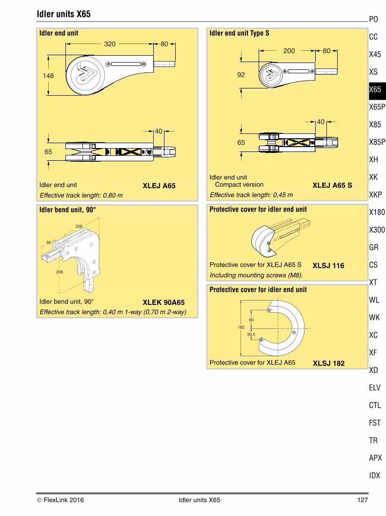
Idler units X65
Idler end unit
Idler end unit XLEJ A65Effective track length: 0,80 m
Idler bend unit, 90°
Idler bend unit, 90° XLEK 90A65Effective track length: 0,40 m 1-way (0,70 m 2-way)
320
65
80
148
40
206
206
80
Idler end unit Type S
Idler end unitCompact version XLEJ A65 S
Effective track length: 0,45 m
Protective cover for idler end unit
Protective cover for XLEJ A65 S XLSJ 116Including mounting screws (M8).
Protective cover for idler end unit
Protective cover for XLEJ A65 XLSJ 182
200
65
80
92
40
60
39,5
182
© FlexLink 2016 Idler units X65 127
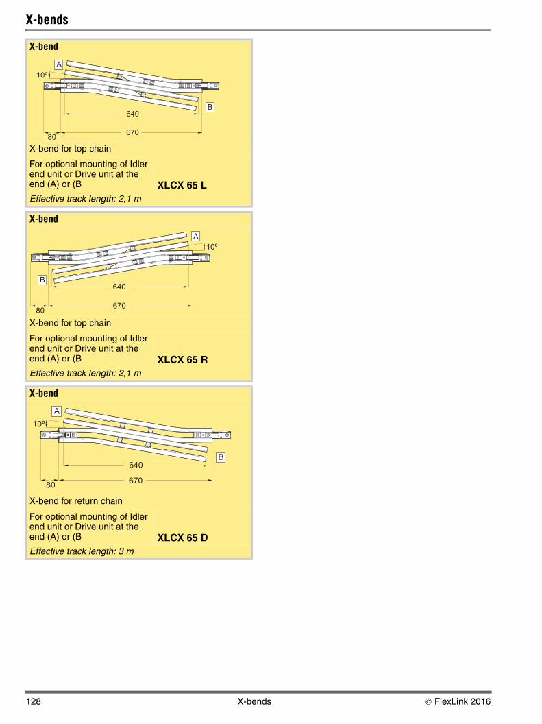
X-bends
X-bend
X-bend for top chain
For optional mounting of Idler end unit or Drive unit at the end (A) or (B XLCX 65 LEffective track length: 2,1 m
X-bend
X-bend for top chain
For optional mounting of Idler end unit or Drive unit at the end (A) or (B XLCX 65 REffective track length: 2,1 m
X-bend
X-bend for return chain
For optional mounting of Idler end unit or Drive unit at the end (A) or (B XLCX 65 DEffective track length: 3 m
67080
640
10º
A
B
67080
640
10º
A
B
67080
10º
640
A
B
128 X-bends © FlexLink 2016
5
5
5P
5
5P
P
80
00
L
K
V
L
T
X
X
PO
CC
X4
XS
X6
X6
X8
X8
XH
XK
XK
X1
X3
GR
CS
XT
W
W
XC
XF
XD
EL
CT
FS
TR
AP
ID
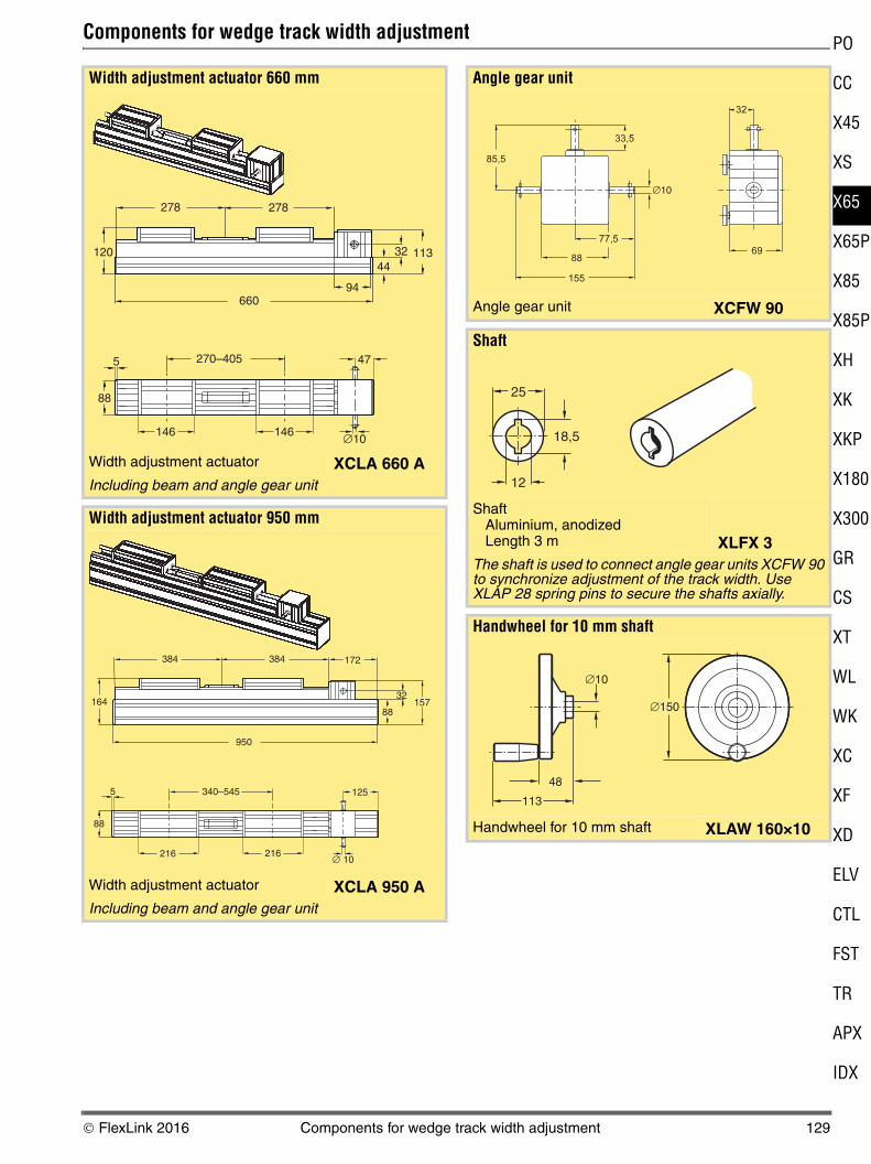
Components for wedge track width adjustment
Width adjustment actuator 660 mm
Width adjustment actuator XCLA 660 AIncluding beam and angle gear unit
Width adjustment actuator 950 mm
Width adjustment actuator XCLA 950 AIncluding beam and angle gear unit
278 278
120
66094
1133244
5
88
146 146 ∅10
47270–405
384384 172
164
950
88
32157
125
∅ 10
5
88
216 216
340–545
Angle gear unit
Angle gear unit XCFW 90
Shaft
ShaftAluminium, anodizedLength 3 m XLFX 3
The shaft is used to connect angle gear units XCFW 90 to synchronize adjustment of the track width. Use XLAP 28 spring pins to secure the shafts axially.
Handwheel for 10 mm shaft
Handwheel for 10 mm shaft XLAW 160×10
25
18,5
12
�10
�150
48
113
© FlexLink 2016 Components for wedge track width adjustment 129
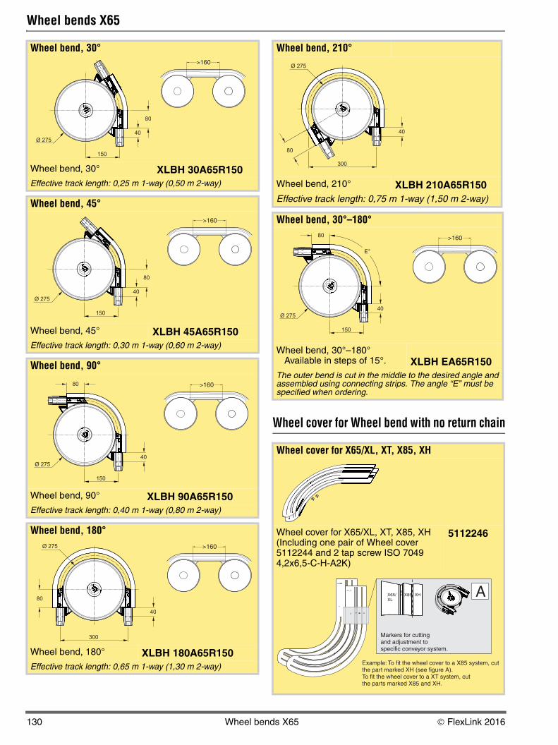
Wheel bends X65
Wheel cover for Wheel bend with no return chain
Wheel bend, 30°
Wheel bend, 30° XLBH 30A65R150Effective track length: 0,25 m 1-way (0,50 m 2-way)
Wheel bend, 45°
Wheel bend, 45° XLBH 45A65R150Effective track length: 0,30 m 1-way (0,60 m 2-way)
Wheel bend, 90°
Wheel bend, 90° XLBH 90A65R150Effective track length: 0,40 m 1-way (0,80 m 2-way)
Wheel bend, 180°
Wheel bend, 180° XLBH 180A65R150Effective track length: 0,65 m 1-way (1,30 m 2-way)
40
150
Ø 275
80
>160
40
150
Ø 275
80
>160
40
150
Ø 275
80 >160
40
300
Ø 275
80
>160
Wheel bend, 210°
Wheel bend, 210° XLBH 210A65R150Effective track length: 0,75 m 1-way (1,50 m 2-way)
Wheel bend, 30°–180°
Wheel bend, 30°–180°Available in steps of 15°. XLBH EA65R150
The outer bend is cut in the middle to the desired angle and assembled using connecting strips. The angle “E” must be specified when ordering.
Wheel cover for X65/XL, XT, X85, XH
Wheel cover for X65/XL, XT, X85, XH (Including one pair of Wheel cover 5112244 and 2 tap screw ISO 7049 4,2x6,5-C-H-A2K)
5112246
40
300
Ø 275
80
40
150
Ø 275
80
E°
>160
X65/XL
XT X85 XH
Markers for cuttingand adjustment tospecific conveyor system.
Example: To fit the wheel cover to a X85 system, cutthe part marked XH (see figure A).To fit the wheel cover to a XT system, cutthe parts marked X85 and XH.
AX65/XL
130 Wheel bends X65 © FlexLink 2016
5
5
5P
5
5P
P
80
00
L
K
V
L
T
X
X
PO
CC
X4
XS
X6
X6
X8
X8
XH
XK
XK
X1
X3
GR
CS
XT
W
W
XC
XF
XD
EL
CT
FS
TR
AP
ID
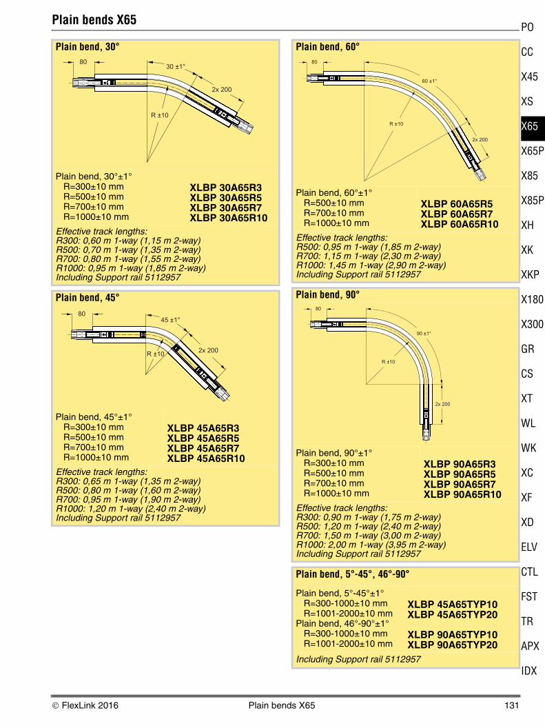
Plain bends X65
Plain bend, 30°
Plain bend, 30°±1°R=300±10 mmR=500±10 mmR=700±10 mmR=1000±10 mm
XLBP 30A65R3XLBP 30A65R5XLBP 30A65R7XLBP 30A65R10
Effective track lengths:R300: 0,60 m 1-way (1,15 m 2-way)R500: 0,70 m 1-way (1,35 m 2-way)R700: 0,80 m 1-way (1,55 m 2-way)R1000: 0,95 m 1-way (1,85 m 2-way)Including Support rail 5112957
Plain bend, 45°
Plain bend, 45°±1°R=300±10 mmR=500±10 mmR=700±10 mmR=1000±10 mm
XLBP 45A65R3XLBP 45A65R5XLBP 45A65R7XLBP 45A65R10
Effective track lengths:R300: 0,65 m 1-way (1,35 m 2-way)R500: 0,80 m 1-way (1,60 m 2-way)R700: 0,95 m 1-way (1,90 m 2-way)R1000: 1,20 m 1-way (2,40 m 2-way)Including Support rail 5112957
30 ±1°
2x 200
R ±10
80
R ±10
8045 ±1°
2x 200
Plain bend, 60°
Plain bend, 60°±1°R=500±10 mmR=700±10 mmR=1000±10 mm
XLBP 60A65R5XLBP 60A65R7XLBP 60A65R10
Effective track lengths:R500: 0,95 m 1-way (1,85 m 2-way)R700: 1,15 m 1-way (2,30 m 2-way)R1000: 1,45 m 1-way (2,90 m 2-way)Including Support rail 5112957
Plain bend, 90°
Plain bend, 90°±1°R=300±10 mmR=500±10 mmR=700±10 mmR=1000±10 mm
XLBP 90A65R3XLBP 90A65R5XLBP 90A65R7XLBP 90A65R10
Effective track lengths:R300: 0,90 m 1-way (1,75 m 2-way)R500: 1,20 m 1-way (2,40 m 2-way)R700: 1,50 m 1-way (3,00 m 2-way)R1000: 2,00 m 1-way (3,95 m 2-way)Including Support rail 5112957
Plain bend, 5°-45°, 46°-90°
Plain bend, 5°-45°±1°R=300-1000±10 mmR=1001-2000±10 mm
Plain bend, 46°-90°±1°R=300-1000±10 mmR=1001-2000±10 mm
XLBP 45A65TYP10XLBP 45A65TYP20
XLBP 90A65TYP10XLBP 90A65TYP20
Including Support rail 5112957
60 ±1°
2x 200
R ±10
80
90 ±1°
2x 200
R ±10
80
© FlexLink 2016 Plain bends X65 131
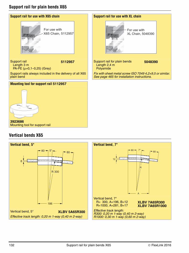
Support rail for plain bends X65
Vertical bends X65
Support rail for use with X65 chain
Support rail Length 3 mPA-PE (μ=0,1–0,25) (Grey)
5112957
Support rails always included in the delivery of all X65 plain bend
Mounting tool for support rail 5112957
3923686Mounting tool for support rail
X65 Chain, 5112957
For use with
Support rail for use with XL chain
Support rail for plain bendsLength 2,4 mPolyamide
5048390
Fix with sheet metal screw ISO 7049 4,2×9,5 or similar. See page 465 for installation instructions.
XL Chain, 5048390
For use with
Vertical bend, 5°
Vertical bend, 5° XLBV 5A65R300Effective track length: 0,20 m 1-way (0,40 m 2-way)
R 300
5°80
186
8
80
Vertical bend, 7°
Vertical bend, 7°R= 300, A=196, B=12R=1000, A=281, B=17
XLBV 7A65R300XLBV 7A65R1000
Effective track length: R300: 0,20 m 1-way (0,40 m 2-way)R1000: 0,30 m 1-way (0,60 m 2-way)
R
7°80
A
12
80
132 Support rail for plain bends X65 © FlexLink 2016
5
5
5P
5
5P
P
80
00
L
K
V
L
T
X
X
PO
CC
X4
XS
X6
X6
X8
X8
XH
XK
XK
X1
X3
GR
CS
XT
W
W
XC
XF
XD
EL
CT
FS
TR
AP
ID
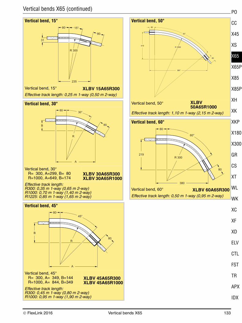
Vertical bends X65 (continued)
Vertical bend, 15°
Vertical bend, 15° XLBV 15A65R300Effective track length: 0,25 m 1-way (0,50 m 2-way)
Vertical bend, 30°
Vertical bend, 30°R= 300, A=299, B= 80R=1000, A=649, B=174
XLBV 30A65R300XLBV 30A65R1000
Effective track length: R300: 0,35 m 1-way (0,65 m 2-way)R1000: 0,70 m 1-way (1,40 m 2-way)R1225: 0,85 m 1-way (1,65 m 2-way)
Vertical bend, 45°
Vertical bend, 45°R= 300, A= 349, B=144R=1000, A= 844, B=349
XLBV 45A65R300XLBV 45A65R1000
Effective track length: R300: 0,45 m 1-way (0,80 m 2-way)R1000: 0,95 m 1-way (1,90 m 2-way)
R 300
15°80
31
80
235
R
30°80
80
A
B
R
45°
80
80
A
B
Vertical bend, 50°
Vertical bend, 50° XLBV 50A65R1000
Effective track length: 1,10 m 1-way (2,15 m 2-way)
Vertical bend, 60°
Vertical bend, 60° XLBV 60A65R300Effective track length: 0,50 m 1-way (0,95 m 2-way)
R 1000
50°
80
80
897
419
R 300
60°
80
80
380
219
© FlexLink 2016 Vertical bends X65 133
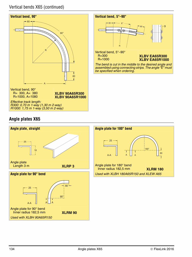
Vertical bends X65 (continued)
Angle plates X65
Vertical bend, 90°
Vertical bend, 90°R= 300, A= 380R=1000, A=1080
XLBV 90A65R300XLBV 90A65R1000
Effective track length: R300: 0,70 m 1-way (1,30 m 2-way)R1000: 1,75 m 1-way (3,50 m 2-way)
R
90°
80
A
80
Vertical bend, 5°–90°
Vertical bend, 5°–90°R=300R=1000
XLBV EA65R300XLBV EA65R1000
The bend is cut in the middle to the desired angle and assembled using connecting strips. The angle “E” must be specified when ordering.
R
E°80
80 9
Angle plate, straight
Angle plateLength 3 m XLRP 3
Angle plate for 90° bend
Angle plate for 90° bendInner radius 182,5 mm XLRM 90
Used with XLBH 90A65R150
25
18
25
A-A A A
90°
80
Angle plate for 180° bend
Angle plate for 180° bendInner radius 182,5 mm XLRM 180
Used with XLBH 180A65R150 and XLEW A65
25
A-A A A
180°
80
134 Angle plates X65 © FlexLink 2016
5
5
5P
5
5P
P
80
00
L
K
V
L
T
X
X
PO
CC
X4
XS
X6
X6
X8
X8
XH
XK
XK
X1
X3
GR
CS
XT
W
W
XC
XF
XD
EL
CT
FS
TR
AP
ID
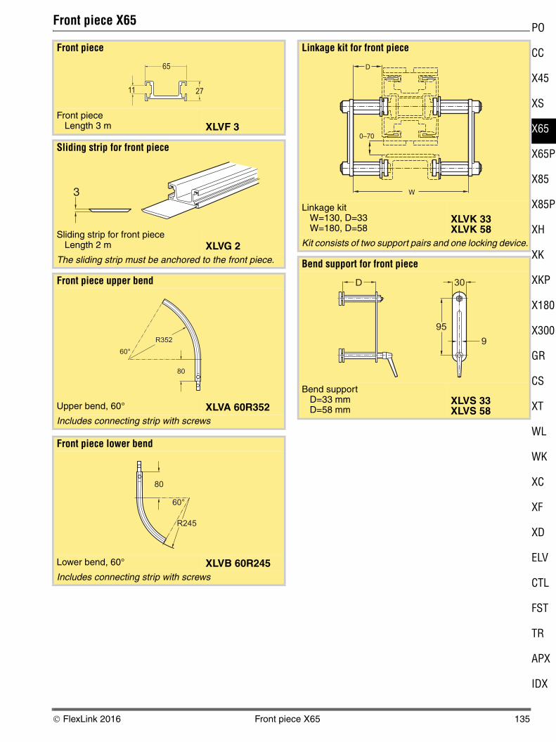
Front piece X65
Front piece
Front pieceLength 3 m XLVF 3
Sliding strip for front piece
Sliding strip for front pieceLength 2 m XLVG 2
The sliding strip must be anchored to the front piece.
Front piece upper bend
Upper bend, 60° XLVA 60R352Includes connecting strip with screws
Front piece lower bend
Lower bend, 60° XLVB 60R245Includes connecting strip with screws
65
2711
3
R352
60°
80
R245
60°
80
Linkage kit for front piece
Linkage kitW=130, D=33W=180, D=58
XLVK 33XLVK 58
Kit consists of two support pairs and one locking device.
Bend support for front piece
Bend support D=33 mm D=58 mm
XLVS 33XLVS 58
D
0–70
W
D 30
95
9
© FlexLink 2016 Front piece X65 135
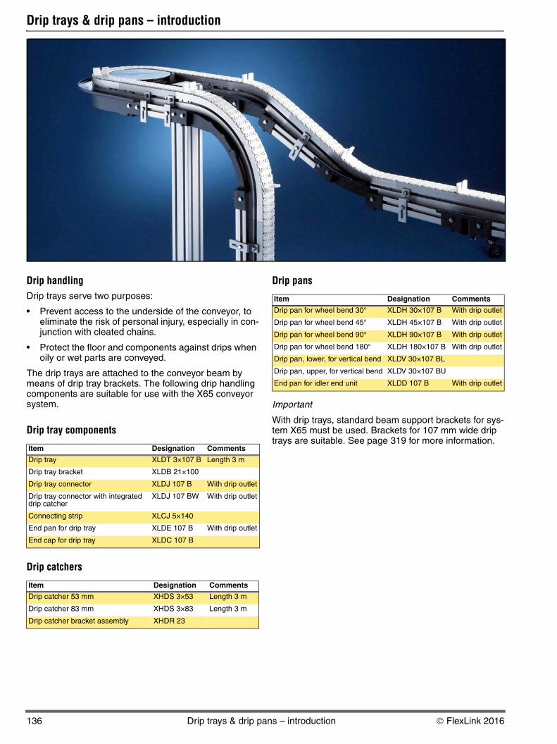
Drip trays & drip pans – introduction
Drip handlingDrip trays serve two purposes:
• Prevent access to the underside of the conveyor, to eliminate the risk of personal injury, especially in con-junction with cleated chains.
• Protect the floor and components against drips when oily or wet parts are conveyed.
The drip trays are attached to the conveyor beam by means of drip tray brackets. The following drip handling components are suitable for use with the X65 conveyor system.
Drip tray components
Drip catchers
Drip pans
Important
With drip trays, standard beam support brackets for sys-tem X65 must be used. Brackets for 107 mm wide drip trays are suitable. See page 319 for more information.
Item Designation Comments
Drip tray XLDT 3×10⁷ B Length 3 m
Drip tray bracket XLDB 21×100
Drip tray connector XLDJ 107 B With drip outlet
Drip tray connector with integrated drip catcher
XLDJ 107 BW With drip outlet
Connecting strip XLCJ 5×140
End pan for drip tray XLDE 107 B With drip outlet
End cap for drip tray XLDC 107 B
Item Designation Comments
Drip catcher 53 mm XHDS 3×53 Length 3 m
Drip catcher 83 mm XHDS 3×83 Length 3 m
Drip catcher bracket assembly XHDR 23
Item Designation Comments
Drip pan for wheel bend 30° XLDH 30×107 B With drip outlet
Drip pan for wheel bend 45° XLDH 45×107 B With drip outlet
Drip pan for wheel bend 90° XLDH 90×107 B With drip outlet
Drip pan for wheel bend 180° XLDH 180×107 B With drip outlet
Drip pan, lower, for vertical bend XLDV 30×107 BL
Drip pan, upper, for vertical bend XLDV 30×107 BU
End pan for idler end unit XLDD 107 B With drip outlet
136 Drip trays & drip pans – introduction © FlexLink 2016
5
5
5P
5
5P
P
80
00
L
K
V
L
T
X
X
PO
CC
X4
XS
X6
X6
X8
X8
XH
XK
XK
X1
X3
GR
CS
XT
W
W
XC
XF
XD
EL
CT
FS
TR
AP
ID
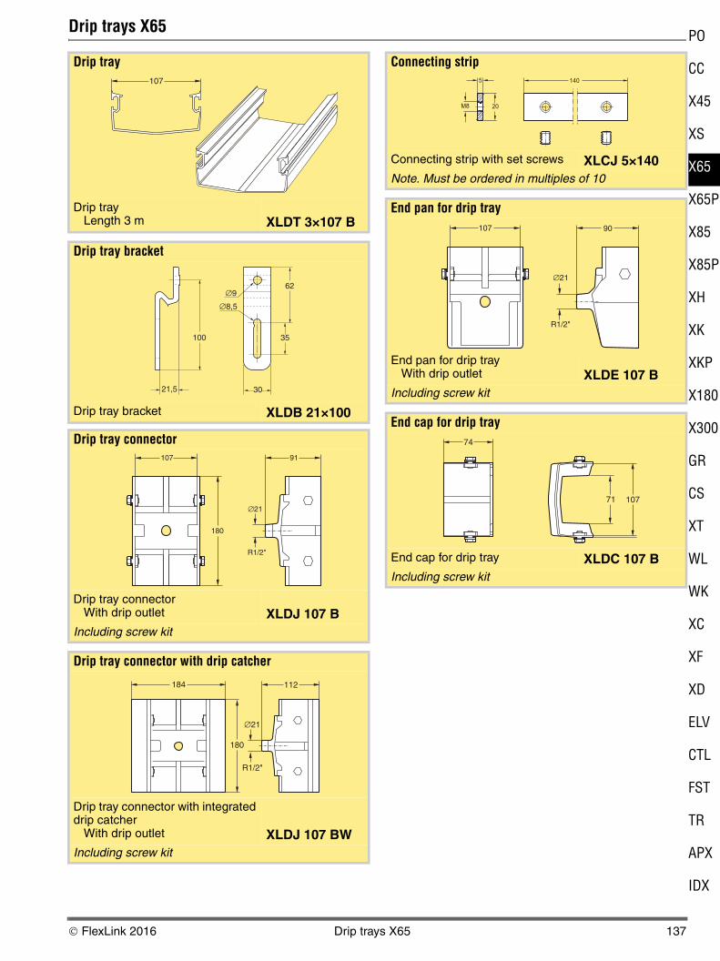
Drip trays X65
Drip tray
Drip trayLength 3 m XLDT 3×10⁷ B
Drip tray bracket
Drip tray bracket XLDB 21×100
Drip tray connector
Drip tray connectorWith drip outlet XLDJ 107 B
Including screw kit
Drip tray connector with drip catcher
Drip tray connector with integrated drip catcher
With drip outlet XLDJ 107 BWIncluding screw kit
107
21,5 30
∅8,5
∅9
100 35
62
180
R1/2"
∅21
107 91
184
180
∅21
R1/2"
112
Connecting strip
Connecting strip with set screws XLCJ 5×140Note. Must be ordered in multiples of 10
End pan for drip tray
End pan for drip tray With drip outlet XLDE 107 B
Including screw kit
End cap for drip tray
End cap for drip tray XLDC 107 BIncluding screw kit
1405
M8 20
107 90
∅21
R1/2"
74
10771
© FlexLink 2016 Drip trays X65 137
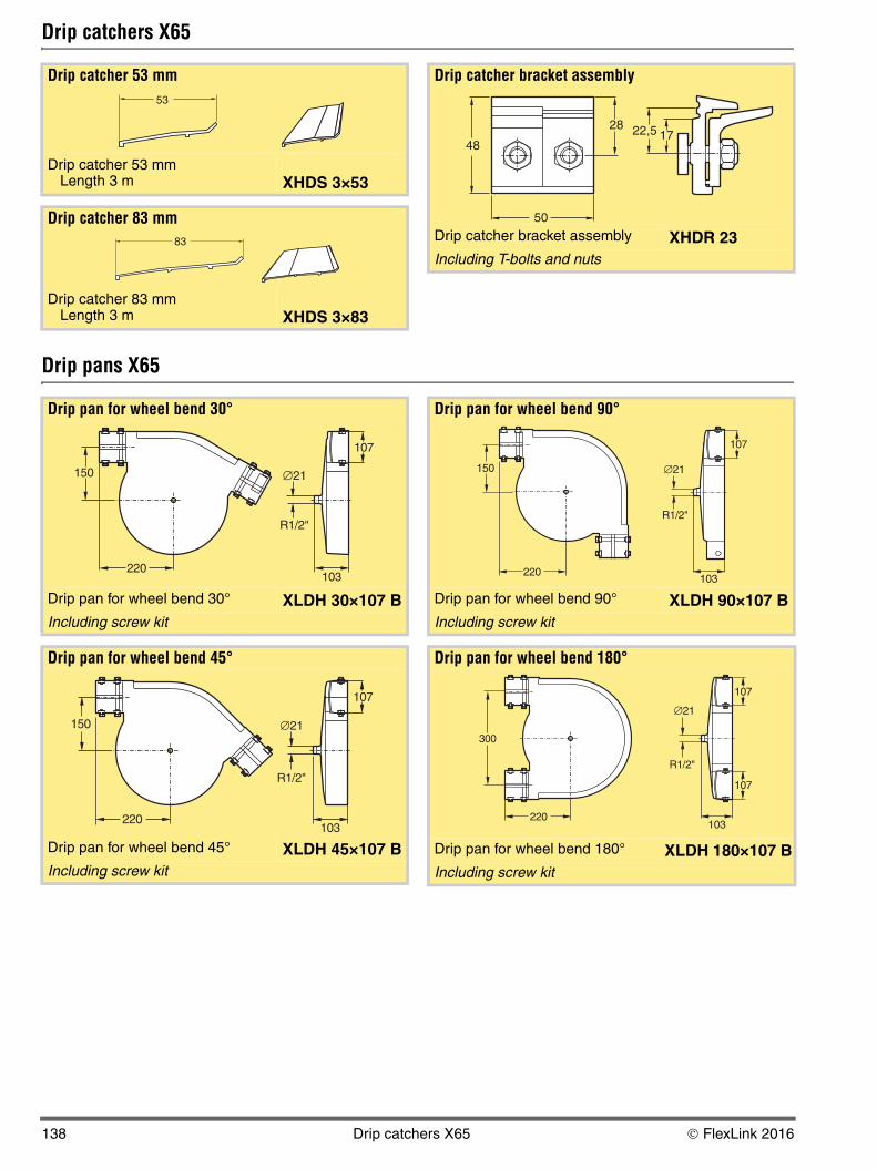
Drip catchers X65
Drip pans X65
Drip catcher 53 mm
Drip catcher 53 mmLength 3 m XHDS 3×53
Drip catcher 83 mm
Drip catcher 83 mmLength 3 m XHDS 3×83
Drip catcher bracket assembly
Drip catcher bracket assembly XHDR 23Including T-bolts and nuts
22,5 1748
28
50
Drip pan for wheel bend 30°
Drip pan for wheel bend 30° XLDH 30×107 BIncluding screw kit
Drip pan for wheel bend 45°
Drip pan for wheel bend 45° XLDH 45×107 BIncluding screw kit
∅21
R1/2"
150
220103
107
∅21
R1/2"
150
220103
107
Drip pan for wheel bend 90°
Drip pan for wheel bend 90° XLDH 90×107 BIncluding screw kit
Drip pan for wheel bend 180°
Drip pan for wheel bend 180° XLDH 180×107 BIncluding screw kit
∅21
R1/2"
150
220
107
103
∅21
R1/2"
107
107
103
300
220
138 Drip catchers X65 © FlexLink 2016
5
5
5P
5
5P
P
80
00
L
K
V
L
T
X
X
PO
CC
X4
XS
X6
X6
X8
X8
XH
XK
XK
X1
X3
GR
CS
XT
W
W
XC
XF
XD
EL
CT
FS
TR
AP
ID
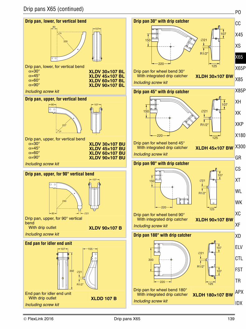
Drip pans X65 (continued)
Drip pan, lower, for vertical bend
Drip pan, lower, for vertical bendα=30°α=45°α=60°α=90°
XLDV 30×107 BLXLDV 45×107 BLXLDV 60×107 BLXLDV 90×107 BL
Including screw kit
Drip pan, upper, for vertical bend
Drip pan, upper, for vertical bendα=30°α=45°α=60°α=90°
XLDV 30×107 BUXLDV 45×107 BUXLDV 60×107 BUXLDV 90×107 BU
Including screw kit
Drip pan, upper, for 90° vertical bend
Drip pan, upper, for 90° vertical bend
With drip outlet XLDV 90×107 BIncluding screw kit
End pan for idler end unit
End pan for idler end unitWith drip outlet XLDD 107 B
Including screw kit
α
10780
330
α
10780
227
107
∅2180
230
392
155
∅21
R1/2"
107
Drip pan 30° with drip catcher
Drip pan for wheel bend 30°With integrated drip catcher XLDH 30×107 BW
Including screw kit
Drip pan 45° with drip catcher
Drip pan for wheel bend 45°With integrated drip catcher XLDH 45×107 BW
Including screw kit
Drip pan 90° with drip catcher
Drip pan for wheel bend 90°With integrated drip catcher XLDH 90×107 BW
Including screw kit
Drip pan 180° with drip catcher
Drip pan for wheel bend 180°With integrated drip catcher XLDH 180×107 BW
Including screw kit
150
220
∅21
125
R1/2"
107
150
220
∅21
R1/2"
125
107
150
220
∅21
R1/2"
125
107
∅21
R1/2"
125
107
107
300
220
© FlexLink 2016 Drip pans X65 139
Drip pans X65 (continued)
Guide rail system
See “Guide rail components” on page 291
Conveyor support
See “Conveyor support components” on page 319
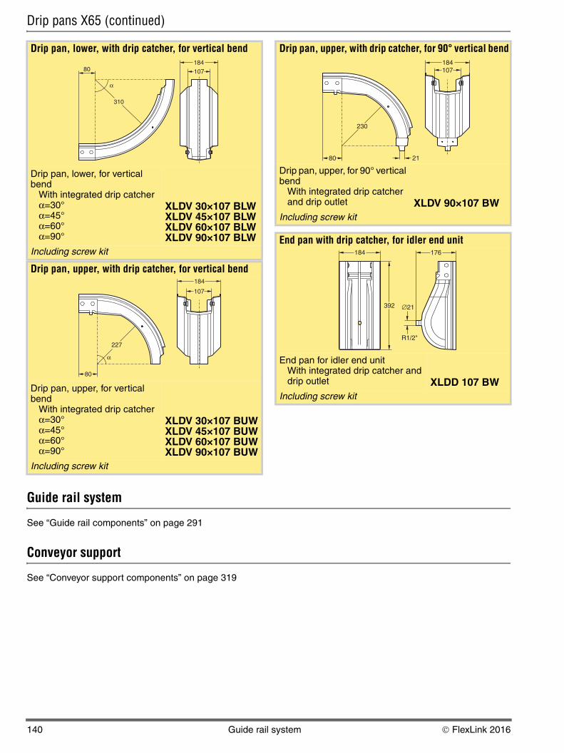
Drip pan, lower, with drip catcher, for vertical bend
Drip pan, lower, for vertical bend
With integrated drip catcherα=30° α=45° α=60° α=90°
XLDV 30×107 BLWXLDV 45×107 BLWXLDV 60×107 BLWXLDV 90×107 BLW
Including screw kit
Drip pan, upper, with drip catcher, for vertical bend
Drip pan, upper, for vertical bend
With integrated drip catcherα=30° α=45° α=60° α=90°
XLDV 30×107 BUWXLDV 45×107 BUWXLDV 60×107 BUWXLDV 90×107 BUW
Including screw kit
α
80
310
184
107
α
80
227
184
107
Drip pan, upper, with drip catcher, for 90° vertical bend
Drip pan, upper, for 90° vertical bend
With integrated drip catcher and drip outlet XLDV 90×107 BW
Including screw kit
End pan with drip catcher, for idler end unit
End pan for idler end unitWith integrated drip catcher and drip outlet XLDD 107 BW
Including screw kit
80 21
230
107184
184
392
176
∅21
R1/2"
140 Guide rail system © FlexLink 2016