Embed Size (px)
Citation preview

8.1.2015
COOLFLEX CLX
Subject to technical modifications.
Table of Contents
2.0 Table of Contents
2.1 System description2.100 System description (general)2.105 System description (data)2.115 COOLFLEX range, DN 20 - DN 125 / SDR 11 (coils)
2.2 Planning, design engineering2.200 Pressure loss chart for water, DN 20 - DN 125 / SDR 112.201 Pressure loss chart for ethylene glycol, DN 20 - DN 125 / SDR 112.210 Heat losses
2.3 Components2.300 House entry bend, 90°2.315 COOLFLEX L-shell, dimension Ø 76 - 126 mm2.316 COOLFLEX Big L-shell, dimension Ø 162 - 182 mm2.320 Joint (PE-HD shrink sleeve), dimension Ø 76 - 182 mm2.325 COOLFLEX I-shell, dimension Ø 76 - 126 mm2.326 COOLFLEX Big I-shell, dimension Ø 162 - 182 mm2.330 COOLFLEX T-shell, dimension Ø 76 - 126 mm2.335 COOLFLEX Big T-shell, dimension Ø 162 - 182 mm
2.345 Insulation material2.350 PE jointing methods, screwed connectors (external thread, weld end, coupling)2.355 PE jointing methods, screwed connectors, T-pieces2.359 PE jointing methods, fusion welded2.360 PE jointing methods, alternative connections
2.365 End closure, shrink-type closure, end cap (LD-PE)2.370 Wall sealing ring for wall openings2.375 Building entry, wall opening2.380 Building entry, core bores/cement pipe liners
2.5 Underground construction, installation2.500 Pipe routing2.505 Trench dimensions2.510 Open installation
2.0
8.1.2015
COOLFLEX CLX
Subject to technical modifications.
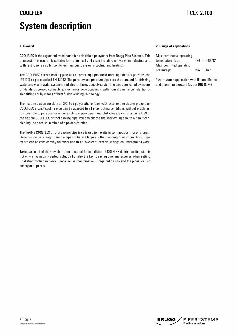
System description
1. General
COOLFLEX is the registered trade name for a flexible pipe system from Brugg Pipe Systems. This pipe system is especially suitable for use in local and district cooling networks, in industrial and with restrictions also for combined heat pump systems (cooling and heating).
The COOLFLEX district cooling pipe has a carrier pipe produced from high-density polyethylene (PE100) as per standard EN 12162. The polyethylene pressure pipes are the standard for drinking water and waste water systems, and also for the gas supply sector. The pipes are joined by means of standard screwed connectors, mechanical pipe couplings, with normal commercial electro fu-sion fittings or by means of butt fusion welding technology. The heat insulation consists of CFC-free polyurethane foam with excellent insulating properties. COOLFLEX district cooling pipe can be adapted to all pipe routing conditions without problems. It is possible to pass over or under existing supply pipes, and obstacles are easily bypassed. With the flexible COOLFLEX district cooling pipe, you can choose the shortest pipe route without con-sidering the classical method of pipe construction.
The flexible COOLFLEX district cooling pipe is delivered to the site in continous coils or on a drum. Generous delivery lengths enable pipes to be laid largely without underground connections. Pipe trench can be considerably narrower and this allows considerable savings on underground work.
Taking account of the very short time required for installation, COOLFLEX district cooling pipe is not only a technically perfect solution but also the key to saving time and expense when setting up district cooling networks, because less coordination is required on site and the pipes are laid simply and quickly.
2. Range of applications
Max. continuous operatingtemperature TBmax: –20 to +40 °C*Max. permitted operatingpressure p: max. 16 bar
*warm water application with limited lifetime and operating pressure (as per DIN 8074)
2.100

8.1.2015
COOLFLEX CLX
Subject to technical modifications.
System description
1. Medium pipe
Material: Polyethylene class PE100 with high density, to DIN EN ISO 12162Life expectancy: 50 years at 20 °C (16 bar) or 40 °C (11.6 bar) as per DIN 8074 (SF 1.25)Properties: suitable as district cooling, cold water and waste water pipe
PE carrier pipe
Density
Thermal conductivity
Tensile strengts
Modulus of elasticity
Linear expansion coefficient
Crystallite melting range
Reference temperature
–
40 °C
20 °C
20 °C
20 °C
–
Value
952 - 960 kg/m³
0.40 W/mK
32 N/mm2
1000 N/mm2
1.8 · 10 E-4 1/K
130 - 135 °C
Test standard
DIN 53479
DIN 52612
DIN 53455
DIN 53457
DIN 52328
–
2. Thermal insulation
Material: CFC-free, 100 % CO2-blown polyurethane foam (PUR)
PUR insulation
Density
Thermal conductivity
Percentage of closed cells
Water absorption after 24 hours
Reference temperature
–
30
–
–
Flexible pipes
DN 20 - DN 125
> 60 kg/m³
≤ 0.0234 W/mK
≥ 90 %
≤ 10 %
Test standard
ISO 845
EN 253 and ISO 8497
–
EN 253
3. Protective casing
Material: linear polyethylene, low density (LLD-PE), seamlessly extruded Purpose: mechanical protection and moisture resistance
LLD-PE protective casing
Density
Thermal conductivity
Crystallite melting range
Reference temperature
–
–
–
Flexible pipes
918 - 922 kg/m³
0.33 W/mK
122 °C
Test standard
ISO 1183
DIN 52612
ISO 11357-3
2.105

8.1.2015
COOLFLEX CLX
Subject to technical modifications.
COOLFLEX rangeDimensions DN 20 - DN 125 / SDR 11 (coils)
Dimensions DN 20 - DN 125 / SDR 11
Type
25/ 76
32/ 76
40/ 91
50/ 91
63/126
75/126
90/162
110/162
125/182
DN
20
25
32
40
50
65
80
100
125
Inches
“
¾
1
1¼
1½
2
2½
3
4
5
PE inner pipe
d x s
mm
25 x 2.3
32 x 2.9
40 x 3.7
50 x 4.6
63 x 5.8
75 x 6.8
90 x 8.2
110 x 10.0
125 x 11.4
Outer casing
D x s1
mm
78 x 2.0
78 x 2.0
93 x 2.2
93 x 2.2
128 x 2.7
128 x 2.7
163 x 3.2
163 x 3.2
183 x 3.3
Minimum
Bending radius
m
0.7
0.7
0.8
0.8
1.0
1.0
1.2
1.2
1.4
Volume
Inner pipe
I/m
0.327
0.539
0.835
1.307
2.091
2.961
4.254
6.362
8.200
Weight
kg/m
0.90
1.00
1.39
1.54
2.60
2.75
4.56
5.69
6.37
Maximum delivery lengths*
Jumbo coil Maxi coil
m m
520 780
520 780
370 570
370 570
192 291
192 291
92 149
92 149
52 86
* Partial lengths can be delivered
- All dimensions are available in straight lengths on request.- We will produce different dimensions or special items on request (> 500 m).- Larger or smaller delivery lengths can be supplied on drums if requested.- Coil dimensions: Jumbo coil outer diameter 2800 mm x 800 mm (width) Maxi coil outer diameter 2800 mm x 1200 mm (width)
PE 100 carrier pipe
PUR foam PE foil LLD-PE casing
s1d
s
D
2.115

8.1.2015
COOLFLEX CLX
Subject to technical modifications.
Velocity
4000
060
000
1000
0030
000
2000
010
000
5000
3000
2000
1000
500
300
4000
20 30 40 50 80 100
200
300
1000
200080
0
500
400
120
140
160
180
1200
1400
1600
1800
25/20.4 mm
(DN 20)
32/26.2 mm
(DN 25)
40/32.6 mm
(DN 32)
50/40.8 mm
(DN 40)
63/51.4 mm
(DN 50)
75/61.4 mm
(DN 65)
90/73.6 mm
(DN 80)
110/90.0 mm
(DN 100)
3.0 m/s
2.0 m/s
1.5 m/s
1.0 m/s
0.75 m/s
0.5 m/s0.4 m
/s
0.3 m/s
Pressure loss ∆p [Pa/m]
125/102.2 mm
(DN 125)
Flow
rate
m [
kg/h
]
Pressure loss chart for water
Water temperature 10 °C
Roughness = 0.01 mm (PE100)(1 mmWS = 9.81 Pa)
DN 20 - DN 125 / SDR 11
2.200

8.1.2015
COOLFLEX CLX
Subject to technical modifications.
Pressure loss chart for ethylene glycol concentration
Medium temperature 10 °CEthylene glycol 30 % concentration
Roughness = 0.01 mm (PE100)(1 mmWS = 9.81 Pa)
Velocity
Flow
rate
m [
kg/h
]
4000
060
000
1000
0030
000
2000
010
000
5000
3000
2000
1000
500
300
4000
20 30 40 50 80 100
200
300
1000
2000
800
500
400
120
140
160
180
1200
1400
1600
1800
25/20.4 mm
(DN 20)
32/26.2 mm
(DN 25)
40/32.6 mm
(DN 32)
50/40.8 mm
(DN 40)
63/51.4 mm
(DN 50)
75/61.4 mm
(DN 65)
90/73.6 mm
(DN 80)
110/90.0 mm
(DN 100)
3.0 m/s
2.0 m/s
1.5 m/s
1.0 m/s
0.75 m/s
0.5 m/s0.4 m
/s
0.3 m/s
DN 20 - DN 125 / SDR 11
Pressure loss ∆p [Pa/m]
125/102.2 mm
(DN 125)
2.201

8.1.2015
COOLFLEX CLX
Subject to technical modifications.
Energy losses
Dimensions DN 20 - DN 40
Heat losses q [W/m]
COOLFLEX U-value Average operating temperature TB [°C]
[W/mK] 6° 8° 10° 12° 14°
25/ 76 - SDR 11 0.1254 –0.5 –0.3 0.0 0.3 0.5
32/ 76 - SDR 11 0.1588 –0.6 –0.3 0.0 0.3 0.6
40/ 91 - SDR 11 0.1657 –0.7 –0.3 0.0 0.3 0.7
50/ 91 - SDR 11 0.2243 –0.9 –0.4 0.0 0.4 0.9
63/126 - SDR 11 0.1941 –0.8 –0.4 0.0 0.4 0.8
75/126 - SDR 11 0.2523 –1.0 –0.5 0.0 0.5 1.0
90/162 - SDR 11 0.2269 –0.9 –0.5 0.0 0.5 0.9
110/162 - SDR 11 0.3287 –1.3 –0.7 0.0 0.7 1.3
125/182 - SDR 11 0.2275 –0.9 –0.5 0.0 0.5 0.9
Installation type CLX:Pipe distance:Covera above pipe:Ground temperature:Soil conductivity:Conductivity of PUR foam:Conductivity of PE pipe: Conductivity of PE casing:
On request, we shall be glad to calculate the heat losses for surface mounted pipe systems.
2-pipe, laid in the grounda = 0.10 mH = 0.60 mTE = 10.00 °ClE = 1.2 W/mKlPU = 0.0234 W/mKlPE = 0.40 W/mKlPE = 0.33 W/mK
Heat loss during operation: q = U (TB -TE) [W/m]U = Heat transfer coefficient [W/mK]TB = Average operating temperature [°C]TE = Average ground temperature [°C]VL = FlowRL = Return
a = 0.1 m
H =
0.6
m
TE lE
Applications laid in the ground
2.210

8.1.2015
COOLFLEX CLX
Subject to technical modifications.
Bend, 90°
Figures in mm
UNO
A
1000
1500
250
Type
25/ 76
32/ 76
40/ 91
50/ 91
63/126
75/126
90/162
110/162
DN
20
25
32
40
50
65
80
100
Dimensions DN 20 - DN 100 / SDR 11
PE inner pipe
d x s
mm
25 x 2.3
32 x 2.9
40 x 3.7
50 x 4.6
63 x 5.8
75 x 6.8
90 x 8.2
110 x 10.0
Outer pipe
D x s1
mm
75 x 4.5
75 x 4.5
90 x 3.5
90 x 3.5
125 x 4.8
125 x 4.8
160 x 4.9
160 x 4.9
Volume
Inner pipe
I/m
0.327
0.539
0.835
1.307
2.091
2.961
4.254
6.362
Inches
“
3/4
1
1 ¼
1 ½
2
2 ½
3
4
2.300

8.1.2015
COOLFLEX CLX
Subject to technical modifications.
COOLFLEX L-shellDimensions DN 20 - DN 65 (Ø 76 - 126 mm)
COOLFLEX L-shell
Outer casing Ø d2
Ø d1 76 91 126
76 x
91 x
126 x
Structure of the half-shell
1 ABS half-shells2 PE fusion welded joints; see CLX 2.359 3 Sealing clamps (14 pcs.)4 Insulation material; see CLX 2.3455 Glued surface6 Reducer ring or sealing ring
PE jointing methods; see CLX 2.350 - 2.360
d1
1
4
3
5
2
6
d2
376
376
Figures in mm
COOLFLEX
COOL
FLEX
2.315

8.1.2015
COOLFLEX CLX
Subject to technical modifications.
COOLFLEX Big L-shellDimensions DN 80 - DN 125 (Ø 162 - 182 mm)
COOLFLEX Big L-shell Structure of the half-shell
1 ABS half-shells2 PE fusion welded joints; see CLX 2.359 3 Sealing clamps (24 pcs.)4 Insulation material; see CLX 2.3455 Glued surface6 Reducer ring or sealing ring
d1
1
4
3
5
2
6
d2
508
508
Figures in mm
COOLFLEX
COOL
FLEX
Outer casing Ø d2
Ø d1 76 91 126 162 182
76
91
126
162 x
182 x
COOLFLEX Big-shells are freely reducible from Ø 182 mm to Ø 76 mmPE jointing methods; see CLX 2.350 - 2.360
2.316

8.1.2015
COOLFLEX CLX
Subject to technical modifications.
Joint using PE-HD shrink sleeve
1 PE fusion welded joints; see CLX 2.3592 Insulation material, PUR or PE; see CLX 2.3453 Shrink sleeve pipe4 Shrink hose
1 2 3 4
COOLFLEX joints and reduction joints
d1 d2
d2
Dimensions Ø 76 - 182 mm
COOLFLEX COOLFLEX
PE jointing methods; see CLX 2.350 - 2.360
2.320
COOLFLEX – COOLFLEX Ø d2 76 91 126 162 182
Ø d1 76 x
91 x x
126 x x x
162 x x
182 x x x

8.1.2015
COOLFLEX CLX
Subject to technical modifications.
COOLFLEX I-shellDimensions DN 20 - DN 65 (Ø 76 - 126 mm)
d2
1 2 543 6
d1
578
COOLFLEX I-shell Structure of the half-shell
1 ABS half-shells2 PE jusion welded joints; see CLX 2.3593 Sealing clamps (12 pcs.)4 Insulation material; see CLX 2.3455 Glued surface6 Reducer ring or sealing ring
Figures in mm
COOLFLEX COOLFLEX
Outer casing Ø d2
Ø d1 76 91 126
76 x
91 x x
126 x x x
PE jointing methods; see CLX 2.350 - 2.360
2.325
8.1.2015
COOLFLEX CLX
Subject to technical modifications.
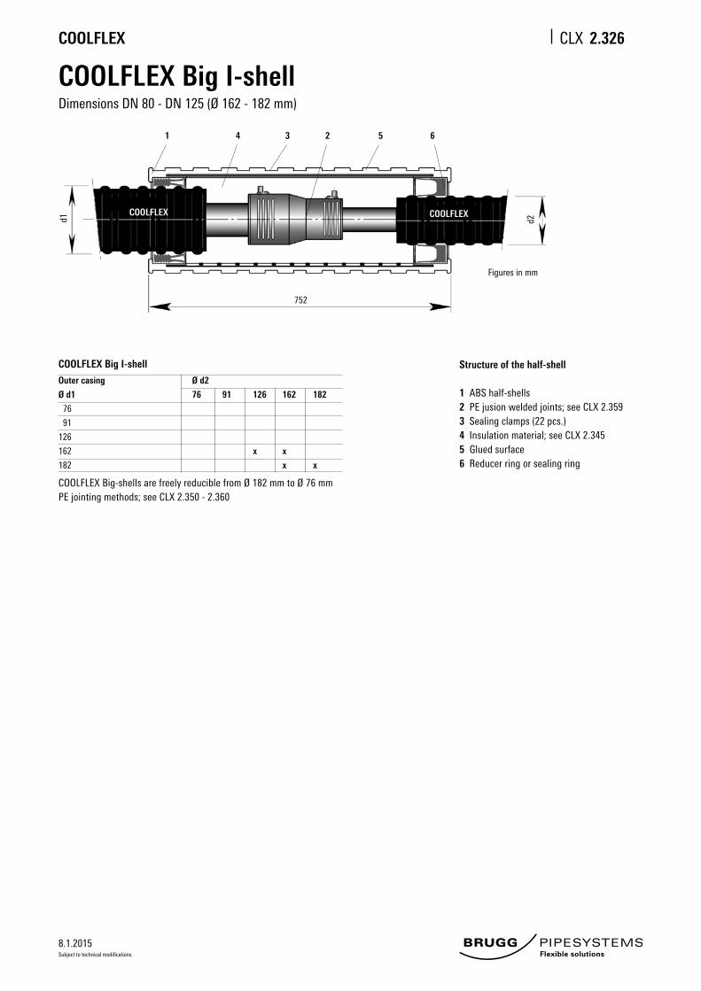
COOLFLEX Big I-shellDimensions DN 80 - DN 125 (Ø 162 - 182 mm)
Structure of the half-shell
1 ABS half-shells2 PE jusion welded joints; see CLX 2.3593 Sealing clamps (22 pcs.)4 Insulation material; see CLX 2.3455 Glued surface6 Reducer ring or sealing ring
COOLFLEX Big I-shell
Outer casing Ø d2
Ø d1 76 91 126 162 182
76
91
126
162 x x
182 x x
COOLFLEX Big-shells are freely reducible from Ø 182 mm to Ø 76 mmPE jointing methods; see CLX 2.350 - 2.360
1 4 3 2 5 6
d2
752
Figures in mm
d1
COOLFLEXCOOLFLEX
2.326
8.1.2015
COOLFLEX CLX
Subject to technical modifications.
1
2 5
4
3
6
d3d1
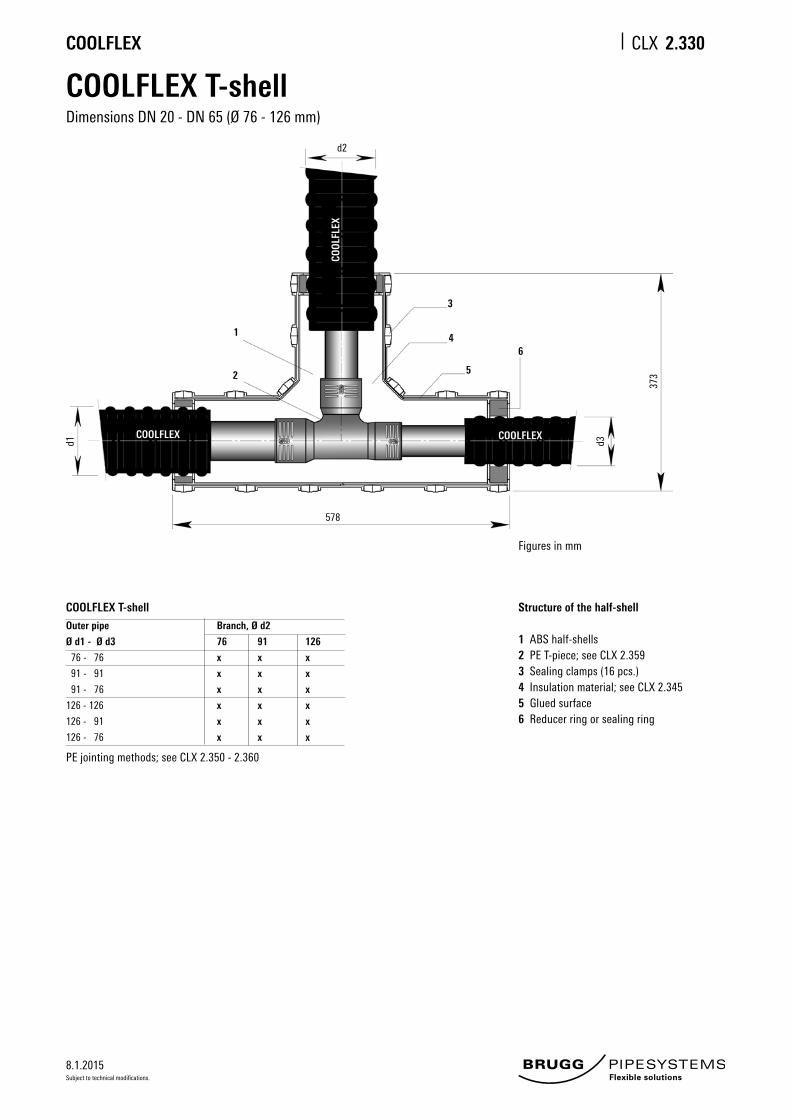
578
373
COOLFLEX COOLFLEX
COOL
FLEX
COOLFLEX T-shellDimensions DN 20 - DN 65 (Ø 76 - 126 mm)
COOLFLEX T-shell
Outer pipe Branch, Ø d2
Ø d1 - Ø d3 76 91 126
76 - 76 x x x
91 - 91 x x x
91 - 76 x x x
126 - 126 x x x
126 - 91 x x x
126 - 76 x x x
Structure of the half-shell
1 ABS half-shells2 PE T-piece; see CLX 2.359 3 Sealing clamps (16 pcs.)4 Insulation material; see CLX 2.3455 Glued surface6 Reducer ring or sealing ring
d2
Figures in mm
PE jointing methods; see CLX 2.350 - 2.360
2.330

8.1.2015
COOLFLEX CLX
Subject to technical modifications.
COOLFLEX Big T-shellDimensions DN 80 - DN 125 (Ø 162 - 182 mm)
COOLFLEX Big T-shellOuter pipe Branch, Ø d2
Ø d1 - Ø d3 76 91 126 162 182
162 - 162 x x x x x
162 - 126 x x x x x
162 - 91 x x x x x
162 - 76 x x x x x
182 - 182 x x x x x
182 - 162 x x x x x
182 - 126 x x x x x
182 - 91 x x x x x
182 - 76 x x x x x
Structure of the half-shell
1 ABS half-shells2 PE T-piece; see CLX 2.359 3 Sealing clamps (27 pcs.)4 Insulation material; see CLX 2.3455 Glued surface6 Reducer ring or sealing ring
d1 d3
752
d2
508
1
2
34
5
Figures in mm
6
COOLFLEX COOLFLEX
COOL
FLEX
PE jointing methods; see CLX 2.350 - 2.360
2.335

8.1.2015
COOLFLEX CLX
Subject to technical modifications.
Insulation materialPUR foam containers (DN 20 - DN 125)
Insulation material for shrink joints and shell systems
PUR foam containers (DN 25 - DN 125)CFC-free, cyclopentane-blown PUR foam in plastic bottles
The required quantity of polyurethane foam is delivered in suitable container sizes for the various joints and T-pieces. The components are supplied separately in two bottles, and are only mixed together when needed. Please note the safety regulations in the installation instructions supplied with the product.
Safety regulations
Protective goggles and gloves must be wornduring the foaming process.
Synthetic gloves
Protective
goggles
2.345
8.1.2015
COOLFLEX CLX
Subject to technical modifications.
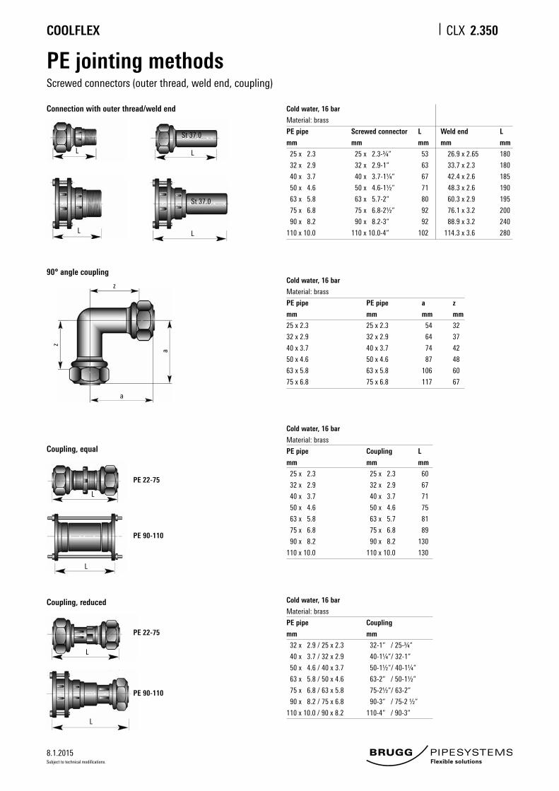
PE jointing methodsScrewed connectors (outer thread, weld end, coupling)
Connection with outer thread/weld end Cold water, 16 bar
Material: brass
PE pipe Screwed connector L Weld end L
mm mm mm mm mm
25 x 2.3 25 x 2.3-¾“ 53 26.9 x 2.65 180
32 x 2.9 32 x 2.9-1“ 63 33.7 x 2.3 180
40 x 3.7 40 x 3.7-1¼“ 67 42.4 x 2.6 185
50 x 4.6 50 x 4.6-1½“ 71 48.3 x 2.6 190
63 x 5.8 63 x 5.7-2“ 80 60.3 x 2.9 195
75 x 6.8 75 x 6.8-2½“ 92 76.1 x 3.2 200
90 x 8.2 90 x 8.2-3“ 92 88.9 x 3.2 240
110 x 10.0 110 x 10.0-4“ 102 114.3 x 3.6 280
L
L
L
L
St 37.0
St 37.0
Cold water, 16 bar
Material: brass
PE pipe PE pipe a z
mm mm mm mm
25 x 2.3 25 x 2.3 54 32
32 x 2.9 32 x 2.9 64 37
40 x 3.7 40 x 3.7 74 42
50 x 4.6 50 x 4.6 87 48
63 x 5.8 63 x 5.8 106 60
75 x 6.8 75 x 6.8 117 67
90° angle coupling
z
z
a
a
Cold water, 16 bar
Material: brass
PE pipe Coupling L
mm mm mm
25 x 2.3 25 x 2.3 60
32 x 2.9 32 x 2.9 67
40 x 3.7 40 x 3.7 71
50 x 4.6 50 x 4.6 75
63 x 5.8 63 x 5.7 81
75 x 6.8 75 x 6.8 89
90 x 8.2 90 x 8.2 130
110 x 10.0 110 x 10.0 130
Coupling, equal
PE 22-75
PE 90-110
L
L
Coupling, reduced Cold water, 16 bar
Material: brass
PE pipe Coupling
mm mm
32 x 2.9 / 25 x 2.3 32-1“ / 25-¾“
40 x 3.7 / 32 x 2.9 40-1¼“/ 32-1“
50 x 4.6 / 40 x 3.7 50-1½“/ 40-1¼“
63 x 5.8 / 50 x 4.6 63-2“ / 50-1½“
75 x 6.8 / 63 x 5.8 75-2½“/ 63-2“
90 x 8.2 / 75 x 6.8 90-3“ / 75-2 ½“
110 x 10.0 / 90 x 8.2 110-4“ / 90-3“
PE 22-75
PE 90-110
L
L
2.350

8.1.2015
COOLFLEX CLX
Subject to technical modifications.
2.355
PE jointing methodsscrewed connectors, T-pieces
Material: brass
Ø d1 Ø d3 Branch, Ø d2
mm mm
25 x 2.3 32 x 2.9 40 x 3.7 50 x 4.6 63 x 5.8 75 x 6.8 90 x 8.2 110 x 10.0
22 x 3.0 - 22 x 3.0
25 x 2.3 - 25 x 2.3 x
28 x 4.0 - 28 x 4.0 x
32 x 2.9 - 32 x 2.9 x x
32 x 2.9 - 28 x 4.0 x
32 x 2.9 - 25 x 2.3 x
40 x 3.7 - 40 x 3.7 x x x
40 x 3.7 - 32 x 2.9 x x
50 x 4.6 - 50 x 4.6 x x x x
50 x 4.6 - 40 x 3.7 x x x
63 x 5.8 - 63 x 5.8 x x x x x
63 x 5.8 - 50 x 4.6 x x x x
75 x 6.8 - 75 x 6.8 x x x x x x
75 x 6.8 - 63 x 5.8 x x x x x
90 x 8.2 - 90 x 8.2 x x x x x x x
90 x 8.2 - 75 x 6.8 x x x x x x
110 x 10.0 - 110 x 10.0 x x x x x x x x
110 x 10.0 - 90 x 8.2 x x x x x x x
Any other T-pieces that may be required can be supplied on request
PE 25 - 75 PE 90 - 110
d2d2
d1 d1d3

8.1.2015
COOLFLEX CLX
Subject to technical modifications.
PE jointing methodsFusion welded
Sleeves
Reduction sleeves
Angle piece, 90° equal
T-pieces
(Source: Georg Fischer AG)
2.359
Cold water, 16 bar
Material: PE 100 / SDR 11
PE pipe Sleeve d1 L
mm mm mm mm
25 x 2.3 25 36 68
32 x 2.9 32 44 72
40 x 3.7 40 54 80
50 x 4.6 50 66 88
63 x 5.8 63 81 96
75 x 6.8 75 96 110
90 x 8.2 90 113 125
110 x 10.0 110 138 145
125 x 11.4 125 154 158
Cold water, 16 bar
Material: PE 100 / SDR 11
PE pipe Sleeve d1 L L1 L2 z
mm mm mm mm mm mm mm
32 x 2.9 / 25 x 2.3 32 / 25 44 79 33 36 10
40 x 3.7 / 32 x 2.9 40 / 32 54 88 33 39 13
50 x 4.6 / 40 x 3.7 50 / 40 66 96 39 43 14
63 x 5.8 / 50 x 4.6 63 / 50 81 106 43 48 15
75 x 6.8 / 63 x 5.8 on request
90 x 8.2 / 75 x 6.8 on request
110 x 8.2 / 90 x 8.2 110 / 90 138 173 73 63 38
125 x 11.4 / 110 x 10.0 on request
Cold water, 16 bar
Material: PE 100 / SDR 11
PE pipe Sleeve d1 L L1 z
mm mm mm mm mm mm
25 x 2.3 25 35 54 34 20
32 x 2.9 32 44 53 36 17
40 x 3.7 40 54 62 39 23
50 x 4.6 50 66 71 43 28
63 x 5.8 63 81 81 48 32
75 x 6.8 75 97 94 54 40
90 x 8.2 90 115 122 62 60
110 x 10.0 110 140 147 72 76
125 x 11.4 125 151 142 74 68
Cold water, 16 bar
Material: PE 100 / SDR 11
PE pipe T-piece d1 L L1 z z1 H
mm mm mm mm mm mm mm mm
25 x 2.3 25 35 90 34 11 92 70
32 x 2.9 32 44 102 36 15 100 74
40 x 3.7 40 54 120 39 21 114 82
50 x 4.6 50 66 135 43 24 126 90
63 x 5.8 63 81 152 48 28 150 102
75 x 6.8 75 97 178 54 35 143 87
90 x 8.2 90 115 205 62 41 161 94
110 x 10.0 110 140 255 72 56 184 104
125 x 11.4 125 161 276 78 60 207 113

8.1.2015
COOLFLEX CLX
Subject to technical modifications.
2.360
Butt-fusion
(Source: PF-Schweisstechnologie GmbH)
PE jointing methodsAlternative connections
Mechanical pipe couplings
To join:plastic to plastic, or plastic to metal pipesØ 40 - 250 mm
(Source: Straub Werke AG)
All jointing methods listed on this sheet are available on request.

8.1.2015
COOLFLEX CLX
Subject to technical modifications.
End closureShrink-type closure, end caps (LD-PE)
Important fitting note
COOLFLEX shrink-on closures must be pushed onto the end of the COOLFLEX pipes before welding the inner pipes and must be protected against the action of heat during welding.
Material:
Heat-shrunk, cross-linked polyolefin. Coated with sealing adhesive
min. 120
Shrink-on closure
COOLFLEX shrink-on closures protect the PUR insulation on the front of the COOLFLEX pipes against splashing water in buildings and shafts. Important: in contact with water (flooding), the shrink-on closure is not necessarily watertight! The shrink-on closure also stops gas escaping from the PUR insulation.
End caps (PE-LD)
End caps are fitted as end closures for dry areas/rooms (up to Ø 182 mm).
min. 120
2.365

8.1.2015
COOLFLEX CLX
Subject to technical modifications.
Wall sealing ringfor wall openings
• To be laid in the ground• Standard roll length: 250 m• Installation depth: see sheet CLX 2.505
Pipe warning tape
Wall sealing ring
COOLFLEX
Type CLX
25/ 76
32/ 76
40/ 91
50/ 91
63/126
75/126
90/162
110/162
125/182
Da
118
118
133
133
168
168
203
203
223
50
Da D
2.370

8.1.2015
COOLFLEX CLX
Subject to technical modifications.
Building entryWall opening
Wall leadthrough
Wall opening Outer casing L min H min
Ø D
mm mm mm
78 450 250
93 540 250
113 580 300
128 640 300
143 640 350
163 680 350
183 720 350
PE connection piece:
see sheet CLX 2.350
End cap:
see sheet CLX 2.365Wall seal: see sheet CLX 2.370
COOLFLEX pipe:
see sheets CLX 2.115
D
approx. 80 mm
80 mm
80 80100D D
L
H
Figures in mm
COOLFLEX
2.375

8.1.2015
COOLFLEX CLX
Subject to technical modifications.
Building entryCore bores/cement pipe liners
Wall leadthrough
Core bores Outer casing D1 A
Ø D
mm mm mm
76 150 180
91 150 180
126 200 230
162 250 280
182 250 280
PE connection piece:
see sheet CLX 2.350
End cap:
see sheet CLX 2.365
COOLFLEX pipe:
see sheets CLX 2.115
D
min. 30
A
D1COOLFLEX
Figures in mm
Core bores
Perfect bores are required for installation. As hairline cracks may be present in the concrete or result from drilling, it is advisable to seal the entire length of the borehole wall with suitable sealant (such as AQUAGARD).
Tightness can only be guaranteed if this recommendation is followed.
Key
1 COOLFLEX2 Sealing set, single-seal, width 1 x 40 mm, Shore hardness D353 Sealing set, double-seal*, width 2 x 40 mm, Shore hardness D354 Liner pipe: made of fiber cement or coated core bore
* Suitable for pressure from water up to 0.5 bar
80 mm
2.380
8.1.2015
COOLFLEX CLX
Subject to technical modifications.
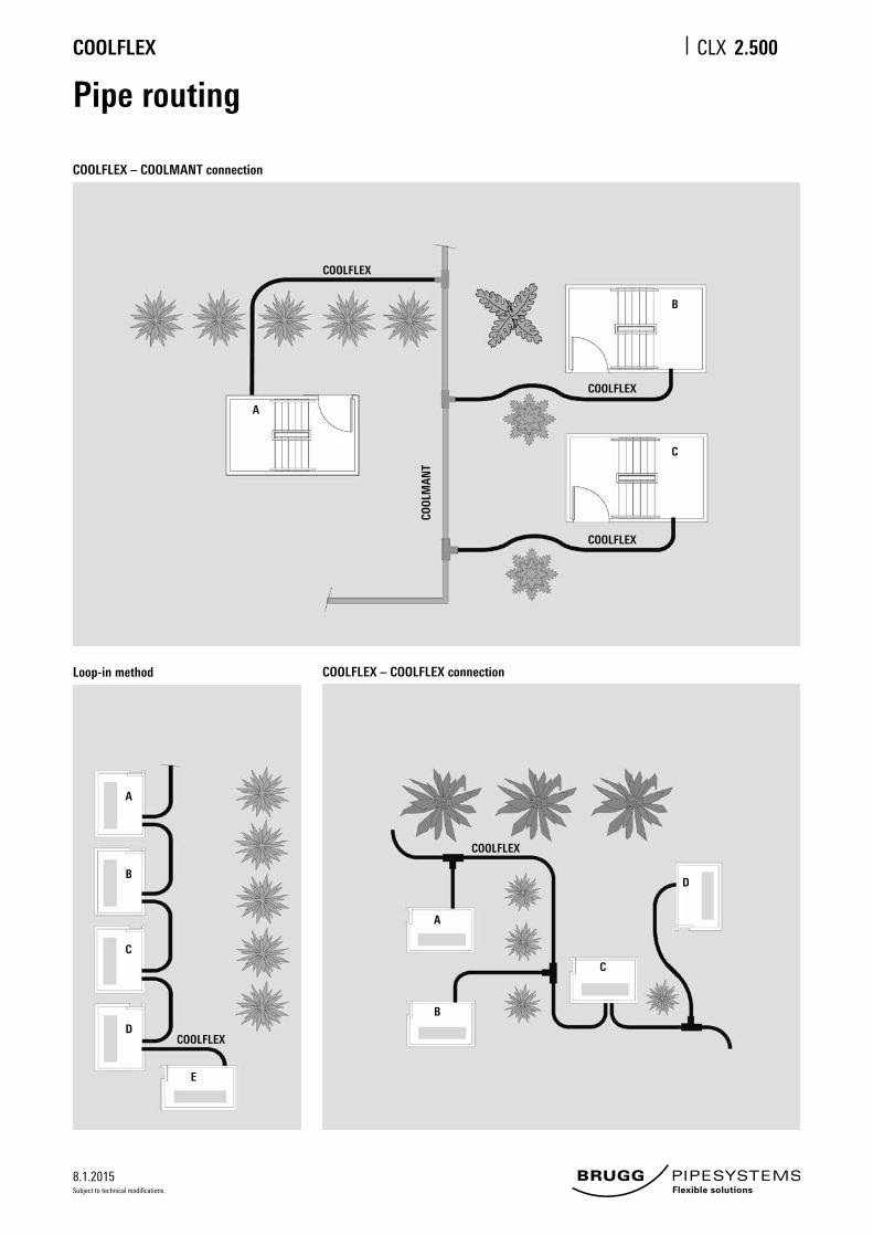
Pipe routing
COOLFLEX – COOLMANT connection
COOLFLEX
A
C
B
COOL
MAN
T
Loop-in method COOLFLEX – COOLFLEX connection
A
B
C
D
E
A
B
C
D
COOLFLEX
COOLFLEX
COOLFLEX
COOLFLEX
2.500

8.1.2015
COOLFLEX CLX
Subject to technical modifications.
Trench dimensions
Trench profile, 2 COOLFLEX pipes (DN 20 - DN 125)
UNO
Casing pipe Width Depth Minimum
Ø D B T Bending radius
mm cm cm m
76 45 80 0.7
91 50 80 0.8
111 55 85 0.9
126 55 85 1.0
162 65 90 1.2
182 70 95 1.4
1 Pipe warning tape; see sheet CLX 2.3702 Excavated material3 Sand, washed, max. grain size 8 mm
SLW 30 = 300 kN total load as per DIN 1072; if subject to higher traffic loads (e.g. SLW 60), a load-distributing superstructure as per RStO75 is required.
With no traffic load, the minimum trench depth T can be reduced by 20 cm.
Installation depth:max. installation depth: 2.6 mOur approval is required for installation at greater depths.
1 2 3
1010
3060
D
T
10 10 10D DB Figures in cm
2.505
8.1.2015
COOLFLEX CLX
Subject to technical modifications.
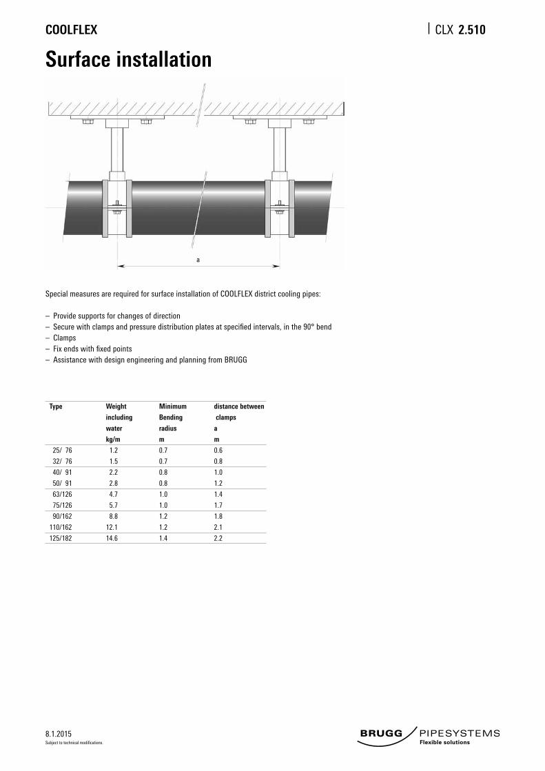
a
Type Weight Minimum distance between
including Bending clamps
water radius a
kg/m m m
25/ 76 1.2 0.7 0.6
32/ 76 1.5 0.7 0.8
40/ 91 2.2 0.8 1.0
50/ 91 2.8 0.8 1.2
63/126 4.7 1.0 1.4
75/126 5.7 1.0 1.7
90/162 8.8 1.2 1.8
110/162 12.1 1.2 2.1
125/182 14.6 1.4 2.2
Special measures are required for surface installation of COOLFLEX district cooling pipes:
– Provide supports for changes of direction– Secure with clamps and pressure distribution plates at specified intervals, in the 90° bend– Clamps– Fix ends with fixed points– Assistance with design engineering and planning from BRUGG
Surface installation
2.510