Embed Size (px)
Citation preview

ISSN: 2277-9655
[Arora* et al., 7(6): June, 2018] Impact Factor: 5.164
IC™ Value: 3.00 CODEN: IJESS7
http: // www.ijesrt.com © International Journal of Engineering Sciences & Research Technology
[331]
IJESRT INTERNATIONAL JOURNAL OF ENGINEERING SCIENCES & RESEARCH
TECHNOLOGY
COOLING PERFORMANCE OF MICRO HEAT PIPE USED FOR MOBILE
ELECTRONIC DEVICES A. Arora *1, M. S. Lodhi 2, R. C. Gupta2
* Department of Mechanical Engineering, Jabalpur Engineering College, Gokalpur, Jabalpur-482011,
Madhya Pradesh, India
DOI: 10.5281/zenodo.1290467
ABSTRACT The paper presents experimental results of cooling performance of micro heat pipe using infra-red Thermography
(IRT) technique for mobile electronic devices and validates those results by using commercial software ANSYS
Fluent 16.1 in which 3-D numerical model is developed and solved by Volume of Fluid (VOF) model. The
computational simulation is performed at constant heat flux applied to the evaporator section and convective
boundary condition at condenser end. The experimental measurements were conducted on micro heat pipe using
distilled water (DW) and Al2O3/water Nano-fluids. The set of experiments were performed to measure the surface
temperature of the micro heat pipe (MHP) by varying cooling fan voltages i.e. 2V, 4V, and 6V. The effective
thermal conductivity, thermal resistance and effectiveness for both phases along the length of micro heat pipe
were calculated. It was observed that the use of Nano-fluid reduces 5-10 oC surface temperature of MHP as
compared to DW, hence use of Nano-fluid as a coolant in MHP improves the thermal performance and reliability
of such devices.
KEYWORDS: Cooling Performance, Micro heat pipe, Nanofluid, Surface temperature, Thermal Resistance.
I. INTRODUCTION Mobile electronic devices, such as smartphones, mini laptops, and tablets are increasing multifunctional and fast.
The heat load of such modern electronic devices had increased as it becomes smaller and denser, however, high
heat generated by internal components and overheating of localized parts in devices has become problematic [1].
This induces thermal stresses in such devices, leading to failure in the components and thus require thermal
management to improve reliability and prevent premature failure. Hence, Effective cooling is essential to remove
heat generated in such compact electronic devices. One of the most efficient methods to dissipate heat from such
compact devices is MHP since they were first introduced by Cotter [2]. MHP has the high efficiency and reliability
and maintains temperature uniformity on the surface of such electronic devices. Even though the space constrained
in electronic devices, micro heat pipes can provide sufficient cooling effects on microelectronic chips due to their
small dimensions, normally with the hydraulic diameter of the order of 100µm and the average length of few
centimeters.
Commonly, water is used as the working fluid in MHP for cooling electronics, as it possesses adequate thermal
and hydrodynamic properties in the required range of operating temperature. However, the thermal conductivity
of water is lower than most of the metals and metal oxides. Therefore, an innovative way to elevate the thermal
conductivity of fluids may be the addition of nanometre-sized metal or metal oxide particles into the base fluid,
called Nanofluids, was first introduced by choi in 1995. The enhancement of thermal conductivity can be
significant and improve the efficiency of fluids used in heat transfer applications [3].
ISSN: 2277-9655
[Arora* et al., 7(6): June, 2018] Impact Factor: 5.164
IC™ Value: 3.00 CODEN: IJESS7
http: // www.ijesrt.com © International Journal of Engineering Sciences & Research Technology
[332]
During the last many years, the use of heat pipes to cool the electronic devices has been rapidly increasing. A heat
pipe for electronics application was introduced to cool the CPU of personal desktop computers [4]. Jang et al. [5]
showed the comparison of the thermal performance of a flat micro heat pipe using both DW and Al2O3/water
Nanofluid and also the effect of volume fraction on thermal performance. Liu et al. [6] analyzed the heat transfer
through the wall of the triangular micro heat pipe with evaporator reaches 63.2% of the temperature difference
between its initial temperature and final steady temperature for heat input of 6W using three different working
fluids. Shahed et al. [7] introduced an ultra-thin heat pipe for various handheld mobile electronic devices such as
smartphones, tablets, camera etc., also developed heat pipe cooling module to eliminate hot spot issue and
conducted several experiments to characterize thermal properties. Moon et al. [8] conducted an experiment to
evaluate thermal performance on micro heat pipe with a triangular and rectangular cross-section of copper material
which operates at a temperature of 60-90oC and dissipates heat up to a thermal load of 7W. Fadhl et al. [9] simulate
the two-phase flow and heat transfer phenomena of a wickless heat pipe with water as working fluid and volume
of fluid (VOF) model was used in ANSYS Fluent and compared those simulation results with experimental
measurements at the same condition. Rahmat et al. [10] investigates and simulates a two-phase model of micro
heat pipe using finite element method and calculate the effective thermal conductivity, pressure and velocity field
along the length of the micro heat pipe and compared to the literature.
As per the author knowledge, the use of MHP to dissipate heat from mobile electronic devices was rarely reported
in the literature. The present experimental study considers the processor chip with a thermal design power (TDP)
of 4.5 W. The experiment was conducted taking such heat as input with 50%, 75% and 100% 0f 4.5W in the
circular MHP test section and to dissipate these by using cooling fan running at different voltages inputs of 2V,
4V and 6V. Also, DW and Al2O3/water Nanofluid were used as working fluid to evaluate the cooling performance,
so that the reliability of such devices increases. Also, compare those experimental results with a computational
simulation using volume of fluid(VOF) model at same operating conditions in ANSYS Fluent.
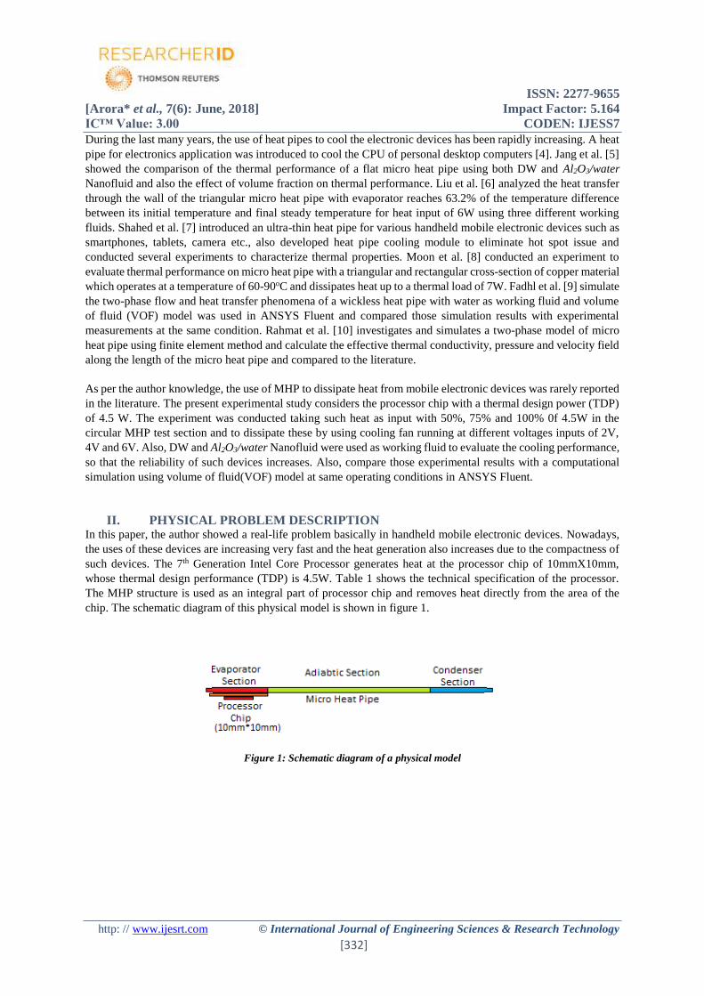
II. PHYSICAL PROBLEM DESCRIPTION In this paper, the author showed a real-life problem basically in handheld mobile electronic devices. Nowadays,
the uses of these devices are increasing very fast and the heat generation also increases due to the compactness of
such devices. The 7th Generation Intel Core Processor generates heat at the processor chip of 10mmX10mm,
whose thermal design performance (TDP) is 4.5W. Table 1 shows the technical specification of the processor.
The MHP structure is used as an integral part of processor chip and removes heat directly from the area of the
chip. The schematic diagram of this physical model is shown in figure 1.
Figure 1: Schematic diagram of a physical model

ISSN: 2277-9655
[Arora* et al., 7(6): June, 2018] Impact Factor: 5.164
IC™ Value: 3.00 CODEN: IJESS7
http: // www.ijesrt.com © International Journal of Engineering Sciences & Research Technology
[333]
Table 1: Technical specification of 7th generation Intel core processor [11]
Specifications Values
Processor Number M7-6Y75
Processor Base Frequency (PBF) 1.20 GHz
TDP 4.5 W
Configurable TDP-up 7 W
Configurable TDP-down 3.5 W
Critical Temperature 50oC
Package Size 20mm*16.5mm
III. DESCRIPTION OF EXPERIMENTAL SETUP The experimental setup was built to carry out the thermal performance investigation on wickless MHP. The MHP
in this study is made of copper (k=385 W/mk) with a diameter of 0.8 mm and a length of 80 mm. It mainly divided
into three sections namely evaporator, adiabatic and condenser sections of lengths 20mm, 40mm and 20mm
respectively. The schematic diagram and working mechanism of the test section of MHP as shown in figure 2.
Figure 2: Schematic diagram and working mechanism of MHP
The setup was composed of MHP, a data acquisition system, thermal IR camera, cooling fan and a DC power
supplying unit as shown in figure 3.
Figure 3: The Experimental Facility
The evaporator of MHP was heated using electric resistance heater and DC power supply unit. A kanthal wire
was used as a resistance heater with 0.274mm wire thickness and 7 Ω/feet resistance, was wound around the outer
wall of evaporator section. A DC dual tracking power supply unit with a rating of 0-30V/3A was used to provide
uniform heating to resistance heater. The condenser of MHP was cooled using a cooling fan with a power rating
of 5V. To measure wall temperature of MHP, Thermal IR camera was used whose spectral range is 3.0-5.0 µm
with a resolution of 640*512 records temperature distribution using IRT technique.

ISSN: 2277-9655
[Arora* et al., 7(6): June, 2018] Impact Factor: 5.164
IC™ Value: 3.00 CODEN: IJESS7
http: // www.ijesrt.com © International Journal of Engineering Sciences & Research Technology
[334]
The specification of design parameters used to conduct the experiment is listed in Table 2.
Table 2: Experimental design conditions [12]
Specifications Parameters Values
Design specifications Power input (W) 4.5
Fan voltage (V) 2-6
Critical temperature (℃) 50
Design constraints Inner Diameter of MHP (𝜇𝑚) 800
Outer Diameter of MHP (𝜇𝑚) 1000
Length of MHP (mm) 80
Working fluids are employed as DW and Al2O3/water with nanoparticle concentration of 2.0% by volume
Nanofluid. The filling ratio(FR) 75%, which is the ratio between the volume of liquid used and the total volume,
was maintained. The heat was supplied at the evaporator section using DC power unit as input with 50%, 75%
and 100% 0f 4.5W and to dissipate these heat to the surrounding by using cooling fan running at different voltages
inputs of 2V, 4V, and 6V. The experiment was conducted with one heat input for these three voltages of the
cooling fan and repeated the same for the other heat inputs. The temperature at the end of the condenser is
maintained at 50oC which is a critical temperature.
IV. DESCRIPTION OF COMPUTATIONAL MODEL In this model, the commercial software ANSYS Fluent 16.1 was used to simulate the two-phase flow for heat
transfer analysis in an MHP. Computational analysis is increasingly developing an approach to solve engineering
problems. This approach involves the simulation of the model and applying the appropriate boundary conditions
for a solution.
A straight circular closed copper tube model was developed with dimensions of 0.8mm diameter and 80mm
length, which consist of three section as an evaporator, adiabatic and condenser sections of 20mm, 40mm, and
80mm lengths respectively. The computational domain as developed in ANSYS shown in figure 4.
Figure 4: Computational domain of MHP
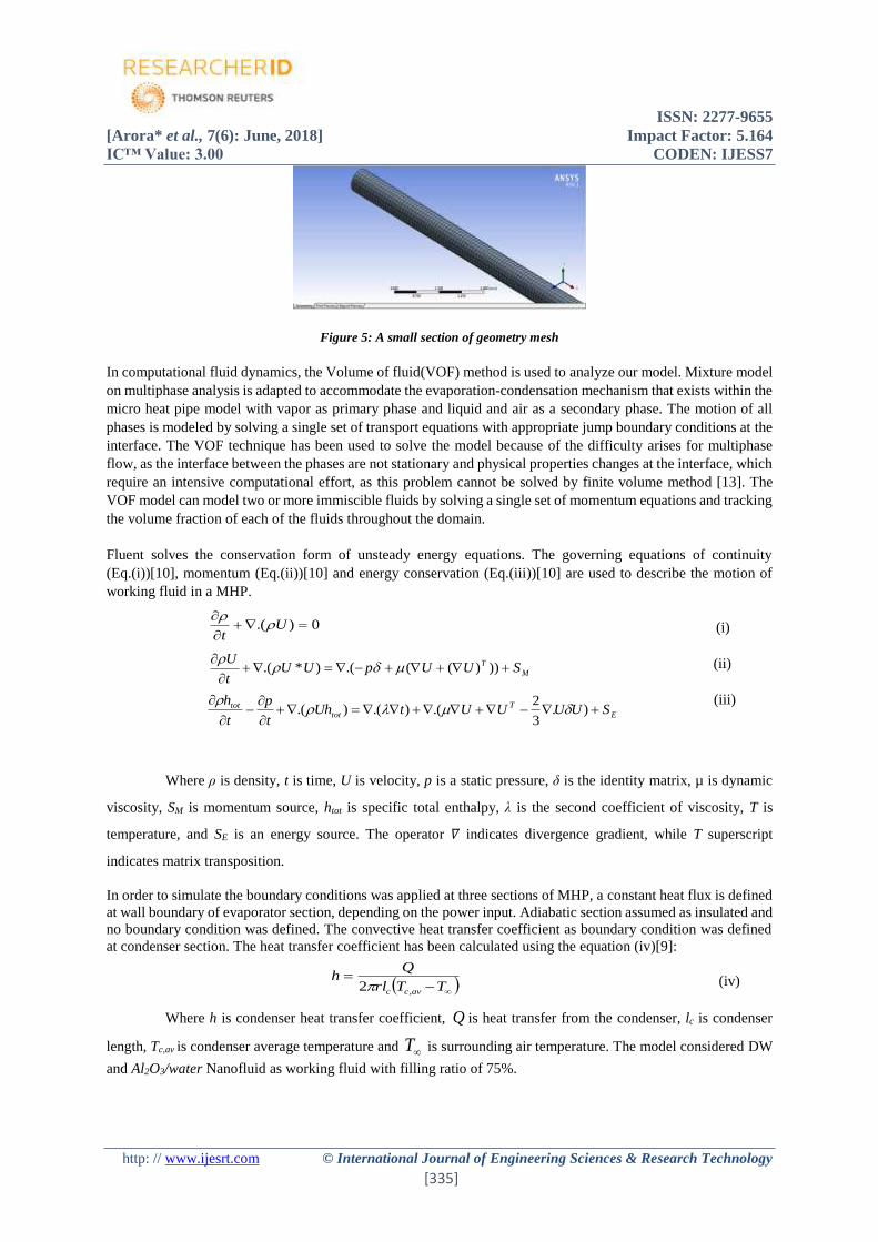
The model meshed as shown in figure 5, which is very fine mesh and discretized into 34452 nodes and 27641
elements.
ISSN: 2277-9655
[Arora* et al., 7(6): June, 2018] Impact Factor: 5.164
IC™ Value: 3.00 CODEN: IJESS7
http: // www.ijesrt.com © International Journal of Engineering Sciences & Research Technology
[335]
Figure 5: A small section of geometry mesh
In computational fluid dynamics, the Volume of fluid(VOF) method is used to analyze our model. Mixture model
on multiphase analysis is adapted to accommodate the evaporation-condensation mechanism that exists within the
micro heat pipe model with vapor as primary phase and liquid and air as a secondary phase. The motion of all
phases is modeled by solving a single set of transport equations with appropriate jump boundary conditions at the
interface. The VOF technique has been used to solve the model because of the difficulty arises for multiphase
flow, as the interface between the phases are not stationary and physical properties changes at the interface, which
require an intensive computational effort, as this problem cannot be solved by finite volume method [13]. The
VOF model can model two or more immiscible fluids by solving a single set of momentum equations and tracking
the volume fraction of each of the fluids throughout the domain.
Fluent solves the conservation form of unsteady energy equations. The governing equations of continuity
(Eq.(i))[10], momentum (Eq.(ii))[10] and energy conservation (Eq.(iii))[10] are used to describe the motion of
working fluid in a MHP.
(i)
(ii)
(iii)
Where ρ is density, t is time, U is velocity, p is a static pressure, δ is the identity matrix, µ is dynamic
viscosity, SM is momentum source, htot is specific total enthalpy, λ is the second coefficient of viscosity, T is
temperature, and SE is an energy source. The operator 𝛻 indicates divergence gradient, while T superscript
indicates matrix transposition.
In order to simulate the boundary conditions was applied at three sections of MHP, a constant heat flux is defined
at wall boundary of evaporator section, depending on the power input. Adiabatic section assumed as insulated and
no boundary condition was defined. The convective heat transfer coefficient as boundary condition was defined
at condenser section. The heat transfer coefficient has been calculated using the equation (iv)[9]:
(iv)
Where h is condenser heat transfer coefficient, Q is heat transfer from the condenser, lc is condenser
length, Tc,av is condenser average temperature and T is surrounding air temperature. The model considered DW
and Al2O3/water Nanofluid as working fluid with filling ratio of 75%.
0).(
U
t
M
T SUUpUUt
U
)))((.()*.(
E
T
tot
tot SUUUUtUht
p
t
h
).
3
2.().().(
TTrl
Qh
avcc ,2

ISSN: 2277-9655
[Arora* et al., 7(6): June, 2018] Impact Factor: 5.164
IC™ Value: 3.00 CODEN: IJESS7
http: // www.ijesrt.com © International Journal of Engineering Sciences & Research Technology
[336]
Thermo-physical properties of Nano fluid are calculated by using equations of density (Eq,(v))[14], Specific heat
(Eq,(vi))[14], thermal conductivity (Eq.(vii))[14] and viscosity (Eq.(viii))[14].
(v)
(vi)
(vii)
(viii)
Where ρnf is density of Nano fluid, ρbf is density of base fluid, ρs is density of solid particle, ϕ is volume
concentration, µnf is viscosity of Nano fluid, µbf is viscosity of base fluid, Cp,nf is the specific heat of Nano fluid,
Cp,bf is specific heat of base fluid, Cp,s is specific heat of solid particle, kbf is thermal conductivity of base fluid and
ks is solid particle thermal conductivity.
A transient simulation is conceded with a time step of 0.005 to calculate the problem and iterate the solution with
200 iterations. The computation performed the solution and converged when the residuals were lower than 1E-4.
V. RESULTS AND DISCUSSION The result of experimental tests on the variation of the voltage cooling fan performance is presented and evaluate
the results with a computational model. In addition, experimental results of using Al2O3-Water Nano-fluid as a
working fluid are compared to the DW. In this paper, the experimental investigation of the micro heat pipe
performance was conducted for the heat input of 4.5 W and evaluates the thermal performance using Infra-Red
(IR) imaging technique to measure and visualize the temperature distribution on the evaporator and condenser
section. Further, the results through experiments were performed to verify by the computational simulation
behavior of MHP throughout the entire length.
Surface Temperature Distribution
Figure 6(a), 6(b) shows the experimental and computational results of the outer surface temperature distribution
along the MHP for heat input of 75% of 4.5W with cooling fan voltage of 6V for DW and Al2O3/water Nanofluid.
Figure 6(a): Experimental and Computational wall temperature distribution for DW
sbfnf )1(
nf
bfpbfsps
nfp
CCC
,,
,
)1(
bf
bfsbfs
bfsbfs
eff kkkkk
kkkkk *
)(2
)(22
bfnf )5.21(

ISSN: 2277-9655
[Arora* et al., 7(6): June, 2018] Impact Factor: 5.164
IC™ Value: 3.00 CODEN: IJESS7
http: // www.ijesrt.com © International Journal of Engineering Sciences & Research Technology
[337]
Figure 6(b): Experimental and Computational wall temperature distribution for Al2O3/water Nanofluid
Table 3 shows the surface average temperature in evaporator (Te) and condenser (Tc) sections between CFD
simulation and experimental results.
Table 3: Comparison between experimental and simulation result for 6V fan voltage
Qin
(4.5W)
Fan
Voltage
(V)
Evaporator (oC) Condenser (oC)
Te,av
Experimental
Te,av
Simulation
Tc,av
Experimental
Tc,av
Simulation
DW 75% 6 109 110 43 37
Al2O3/water
Nano fluid
6 104 106 42 37
The distance between 0 to 20 mm shows the evaporator section where, in the experiment, a heat resistance wire
is wrapped around it to provide uniform heating through DC power supply. The distance between 20-60 mm
shows adiabatic section where there is no heat loss and the temperature raised in this section due to axial
conduction heat transfer. The distance between 60-80 mm shows the condenser section where heat dissipates by
air circulation around it through the cooling fan. In case of Simulation, similar boundary condition applied on a
computational model where constant heat flux was provided on evaporator section, no heat loss in adiabatic
section and convective heat transfer coefficient on condenser section. The Simulation evaporator average
temperature has deviated from experimental results by 3-4oC.
Maximum Surface Temperature
The maximum surface temperature of MHP for different base frequencies of 4.5W heat input is shown in figure
7. The result shows that the surface temperature decreases along the length of the MHP and occur
(a) 50% PBF (b) 75% PBF
86
88
90
92
94
96
98
1 2 3 4 5 6 7
EVA
PO
RA
TOR
TEM
PER
ATU
RE
FAN VOLTAGE(V)
DW NF
115
120
125
130
135
140
1 2 3 4 5 6 7
EVA
PO
RA
TOR
TEM
PER
ATU
RE
FAN VOLTAGE(V)
DW NF
ISSN: 2277-9655
[Arora* et al., 7(6): June, 2018] Impact Factor: 5.164
IC™ Value: 3.00 CODEN: IJESS7
http: // www.ijesrt.com © International Journal of Engineering Sciences & Research Technology
[338]
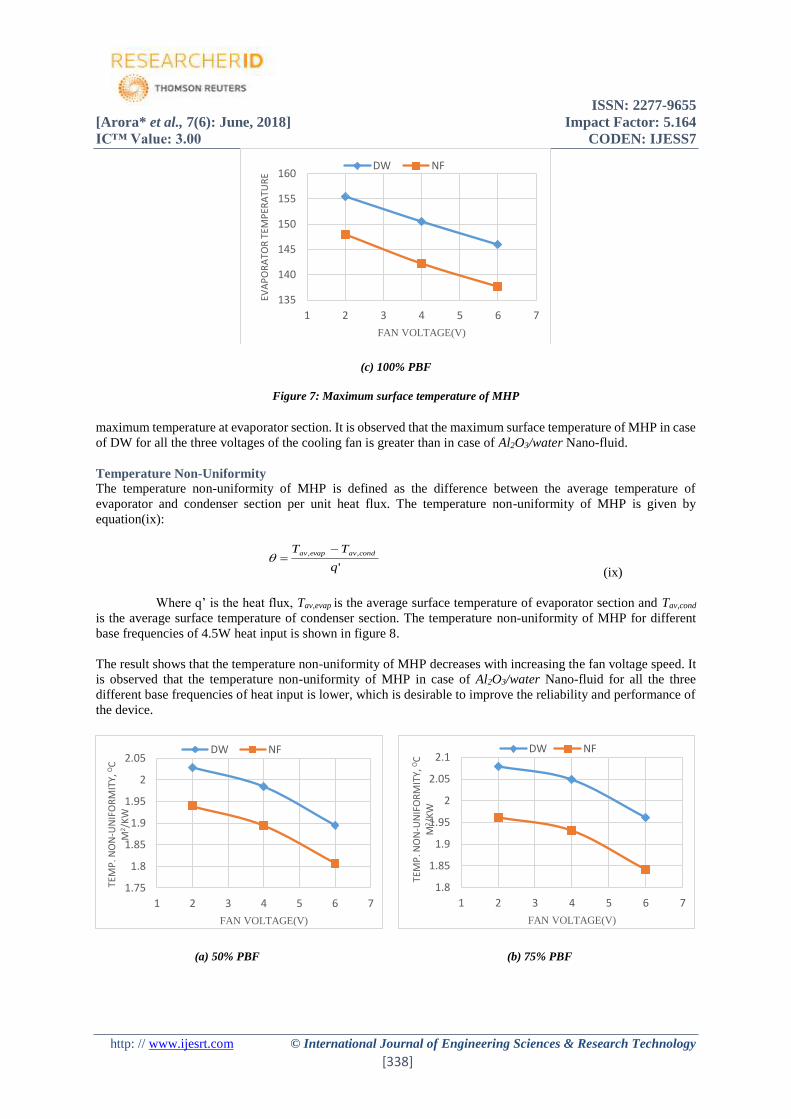
(c) 100% PBF
Figure 7: Maximum surface temperature of MHP
maximum temperature at evaporator section. It is observed that the maximum surface temperature of MHP in case
of DW for all the three voltages of the cooling fan is greater than in case of Al2O3/water Nano-fluid.
Temperature Non-Uniformity
The temperature non-uniformity of MHP is defined as the difference between the average temperature of
evaporator and condenser section per unit heat flux. The temperature non-uniformity of MHP is given by
equation(ix):
'
,,
q
TT condavevapav
(ix)
Where q’ is the heat flux, Tav,evap is the average surface temperature of evaporator section and Tav,cond
is the average surface temperature of condenser section. The temperature non-uniformity of MHP for different
base frequencies of 4.5W heat input is shown in figure 8.
The result shows that the temperature non-uniformity of MHP decreases with increasing the fan voltage speed. It
is observed that the temperature non-uniformity of MHP in case of Al2O3/water Nano-fluid for all the three
different base frequencies of heat input is lower, which is desirable to improve the reliability and performance of
the device.
(a) 50% PBF (b) 75% PBF
135
140
145
150
155
160
1 2 3 4 5 6 7
EVA
PO
RA
TOR
TEM
PER
ATU
RE
FAN VOLTAGE(V)
DW NF
1.75
1.8
1.85
1.9
1.95
2
2.05
1 2 3 4 5 6 7
TEM
P. N
ON
-UN
IFO
RM
ITY,
OC
M
2 /K
W
FAN VOLTAGE(V)
DW NF
1.8
1.85
1.9
1.95
2
2.05
2.1
1 2 3 4 5 6 7
TEM
P. N
ON
-UN
IFO
RM
ITY,
OC
M
2 /K
W
FAN VOLTAGE(V)
DW NF

ISSN: 2277-9655
[Arora* et al., 7(6): June, 2018] Impact Factor: 5.164
IC™ Value: 3.00 CODEN: IJESS7
http: // www.ijesrt.com © International Journal of Engineering Sciences & Research Technology
[339]
(c) 100% PBF
Figure 8: Temperature non-uniformity of MHP
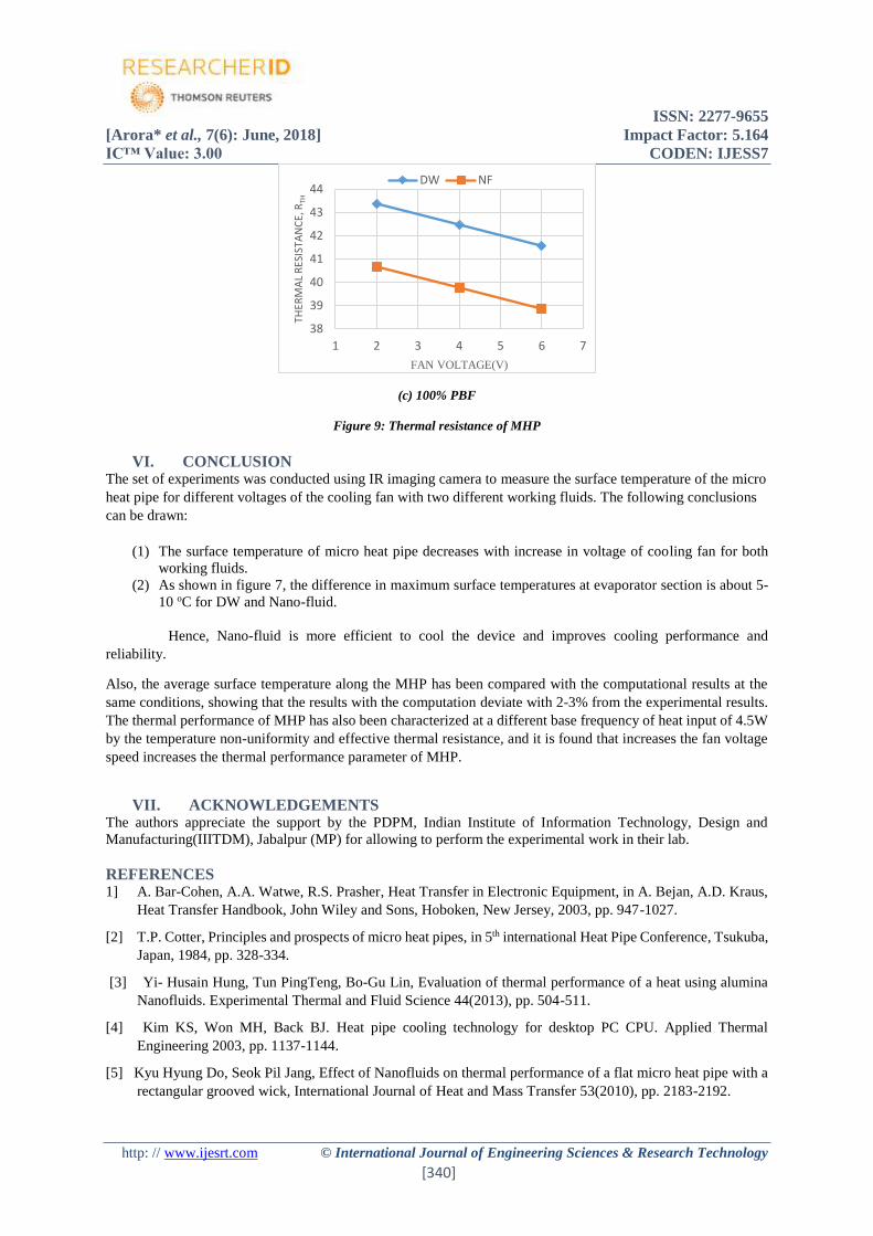
Thermal Resistance
The thermal resistance of MHP is defined as the ratio between the surface average temperature difference of
evaporator and condenser to the heat input. The thermal resistance is calculated by using equation (x):
in
condavevapav
thQ
TTR
,,
(x)
Where Q in is the heat input, Tav,evap is the average surface temperature of evaporator section and Tav,cond
is the average surface temperature of condenser section. The thermal resistance of MHP for different base
frequencies of 4.5W heat input is shown in figure 9.
The result shows that the thermal resistance of MHP decreases with increasing the fan voltage speed. It is observed
that the thermal resistance of MHP in case of DW for all the three different base frequencies of heat input of 4.5W
is greater than in case of Al2O3/water Nano-fluid.
(a) 50% PBF (b) 75% PBF
1.9
1.95
2
2.05
2.1
2.15
2.2
1 2 3 4 5 6 7
TEM
P. N
ON
-UN
IFO
RM
ITY,
OC
M
2 /K
W
FAN VOLTAGE(V)
DW NF
35
36
37
38
39
40
41
1 2 3 4 5 6 7
THER
MA
L R
ESIS
TAN
CE,
RTH
FAN VOLTAGE(V)
DW NF
36
37
38
39
40
41
42
1 2 3 4 5 6 7
THER
MA
L R
ESIS
TAN
CE,
RTH
FAN VOLTAGE(V)
DW NF
ISSN: 2277-9655
[Arora* et al., 7(6): June, 2018] Impact Factor: 5.164
IC™ Value: 3.00 CODEN: IJESS7
http: // www.ijesrt.com © International Journal of Engineering Sciences & Research Technology
[340]
(c) 100% PBF
Figure 9: Thermal resistance of MHP
VI. CONCLUSION The set of experiments was conducted using IR imaging camera to measure the surface temperature of the micro
heat pipe for different voltages of the cooling fan with two different working fluids. The following conclusions
can be drawn:
(1) The surface temperature of micro heat pipe decreases with increase in voltage of cooling fan for both
working fluids.
(2) As shown in figure 7, the difference in maximum surface temperatures at evaporator section is about 5-
10 oC for DW and Nano-fluid.
Hence, Nano-fluid is more efficient to cool the device and improves cooling performance and
reliability.
Also, the average surface temperature along the MHP has been compared with the computational results at the
same conditions, showing that the results with the computation deviate with 2-3% from the experimental results.
The thermal performance of MHP has also been characterized at a different base frequency of heat input of 4.5W
by the temperature non-uniformity and effective thermal resistance, and it is found that increases the fan voltage
speed increases the thermal performance parameter of MHP.
VII. ACKNOWLEDGEMENTS The authors appreciate the support by the PDPM, Indian Institute of Information Technology, Design and
Manufacturing(IIITDM), Jabalpur (MP) for allowing to perform the experimental work in their lab.
REFERENCES 1] A. Bar-Cohen, A.A. Watwe, R.S. Prasher, Heat Transfer in Electronic Equipment, in A. Bejan, A.D. Kraus,
Heat Transfer Handbook, John Wiley and Sons, Hoboken, New Jersey, 2003, pp. 947-1027.
[2] T.P. Cotter, Principles and prospects of micro heat pipes, in 5th international Heat Pipe Conference, Tsukuba,
Japan, 1984, pp. 328-334.
[3] Yi- Husain Hung, Tun PingTeng, Bo-Gu Lin, Evaluation of thermal performance of a heat using alumina
Nanofluids. Experimental Thermal and Fluid Science 44(2013), pp. 504-511.
[4] Kim KS, Won MH, Back BJ. Heat pipe cooling technology for desktop PC CPU. Applied Thermal
Engineering 2003, pp. 1137-1144.
[5] Kyu Hyung Do, Seok Pil Jang, Effect of Nanofluids on thermal performance of a flat micro heat pipe with a
rectangular grooved wick, International Journal of Heat and Mass Transfer 53(2010), pp. 2183-2192.
38
39
40
41
42
43
44
1 2 3 4 5 6 7
THER
MA
L R
ESIS
TAN
CE,
RTH
FAN VOLTAGE(V)
DW NF

ISSN: 2277-9655
[Arora* et al., 7(6): June, 2018] Impact Factor: 5.164
IC™ Value: 3.00 CODEN: IJESS7
http: // www.ijesrt.com © International Journal of Engineering Sciences & Research Technology
[341]
[6] X. Liu, Y. Chen. Transient thermal performance analysis of micro heat pipes, Applied Thermal Engineering
58(2013), pp. 585-593
[7] Ahamed Mohammad Shahed, Yuji Saito, Makoto Takahashi, High-performance ultra-thin heat pipe cooling
module for mobile handheld electronic devices, Fujikura Technical Review, 2017, pp. 40-46.
[8] Seok Hwan Moon, Gunn Hwang, Sang ChoonKo, Youn Tae Kim, Experimental study on thermal
performance of micro heat pipe with a cross-section of the polygon, Microelectronics Reliability 44(2004),
pp. 315-321.
[9] Bandar Fadhl, Luiz C. Wrobel, HussamJouhara, Numerical modeling of temperature distribution in a two-
phase closed thermosiphon, Applied Thermal Engineering 60(2013), pp. 122-131.
[10] Meysam Rahmat, Pascal Hubert, Two-phase simulations of micro heat pipes, Computers & Fluids 39(2010),
pp. 451-460.
[11] Intel Website, Intel Core ‘m’ series processor (4M cache, up to 3.10GHz), Essential technical specification.
[12] M. S. Lodhi, R. C. Gupta, The experimental study of the thermal performance of heat pipe using CuO/water
nanofluid, International Journal of Engineering Science and Research Technology, Vol. 2(Issue 8), 2013,
pp. 2048-2054.
[13] ANSYS FLUENT Theory Guide (Release 13.0), Multiphase Flows, ANSYS, Inc., November 2010,
Chapter-17, pp. 455-568.
[14] Dhinesh Kumar Devendiran, Valan Arasu Amirtham, A review on preparation, characterization, properties,
and applications of Nano fluids, Renewable and Sustainable Energy Reviews 60(2016), pp. 21-40.


![Calculation Method for Forced-Air Convection Cooling Heat ... · tion cooling [1], forced-air convection cool ing, heat pipe cooling [2], and liquid cooling. F orced -air convection](https://img.pdfslide.net/doc/110x75/5e6929cd70728524d16ffef2/calculation-method-for-forced-air-convection-cooling-heat-tion-cooling-1.jpg)