Embed Size (px)
Citation preview
NLS2012124Enclosure
NLS2012124
ENCLOSURE
COOPER NUCLEAR STATION FLOODING WALKDOWN REPORT
HNebraska Public Power District
"Always there when you need us"
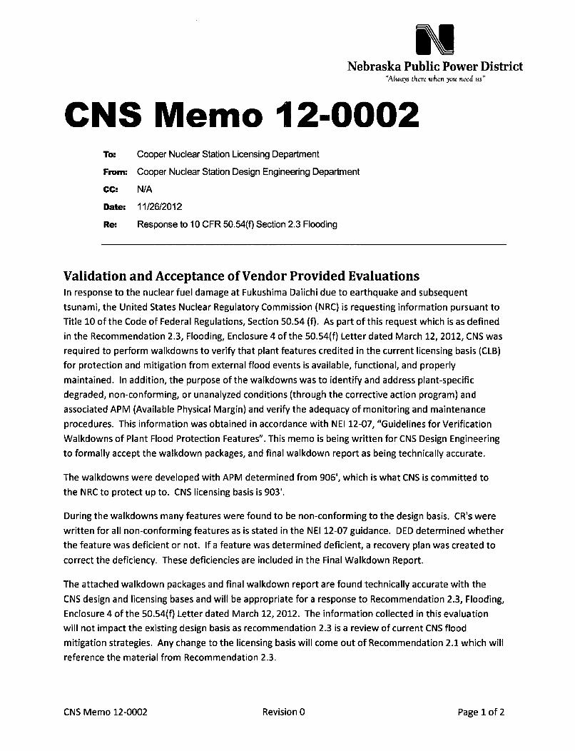
CNS Memo 12-0002To: Cooper Nuclear Station Licensing Department
From: Cooper Nuclear Station Design Engineering Department
CC: N/A
Date: 11/26/2012
Re: Response to 10 CFR 50.54(f) Section 2.3 Flooding
Validation and Acceptance of Vendor Provided EvaluationsIn response to the nuclear fuel damage at Fukushima Daiichi due to earthquake and subsequent
tsunami, the United States Nuclear Regulatory Commission (NRC) is requesting information pursuant to
Title 10 of the Code of Federal Regulations, Section 50.54 (f). As part of this request which is as defined
in the Recommendation 2.3, Flooding, Enclosure 4 of the 50.54(f) Letter dated March 12, 2012, CNS was
required to perform walkdowns to verify that plant features credited in the current licensing basis (CLB)
for protection and mitigation from external flood events is available, functional, and properly
maintained. In addition, the purpose of the walkdowns was to identify and address plant-specific
degraded, non-conforming, or unanalyzed conditions (through the corrective action program) and
associated APM (Available Physical Margin) and verify the adequacy of monitoring and maintenance
procedures. This information was obtained in accordance with NEI 12-07, "Guidelines for Verification
Walkdowns of Plant Flood Protection Features". This memo is being written for CNS Design Engineering
to formally accept the walkdown packages, and final walkdown report as being technically accurate.
The walkdowns were developed with APM determined from 906', which is what CNS is committed to
the NRC to protect up to. CNS licensing basis is 903'.
During the walkdowns many features were found to be non-conforming to the design basis. CR's were
written for all non-conforming features as is stated in the NEI 12-07 guidance. DED determined whether
the feature was deficient or not. If a feature was determined deficient, a recovery plan was created to
correct the deficiency. These deficiencies are included in the Final Walkdown Report.
The attached walkdown packages and final walkdown report are found technically accurate with the
CNS design and licensing bases and will be appropriate for a response to Recommendation 2.3, Flooding,
Enclosure 4 of the 50.54(q Letter dated March 12, 2012. The information collected in this evaluation
will not impact the existing design basis as recommendation 2.3 is a review of current CNS flood
mitigation strategies. Any change to the licensing basis will come out of Recommendation 2.1 which will
reference the material from Recommendation 2.3.
CNS Memo 12-0002 Revision 0 Page 1 of 2

ATTACHMENTS:
Final walkdown report
Walkdown packages
Walkdown team credentials
CNS Design Engineer
CNS Design EngineeringSupervisor
CNS Design EngineeringManager
Matthew Nienaber
Brian T. Wolken
Roman M. Estrada
/if26 2ý
IfZ~
CNS Memo DED 12-0002 Revision 0 Page 2 of 2

Page I of 36
CNS Flooding Walkdown Submittal Report
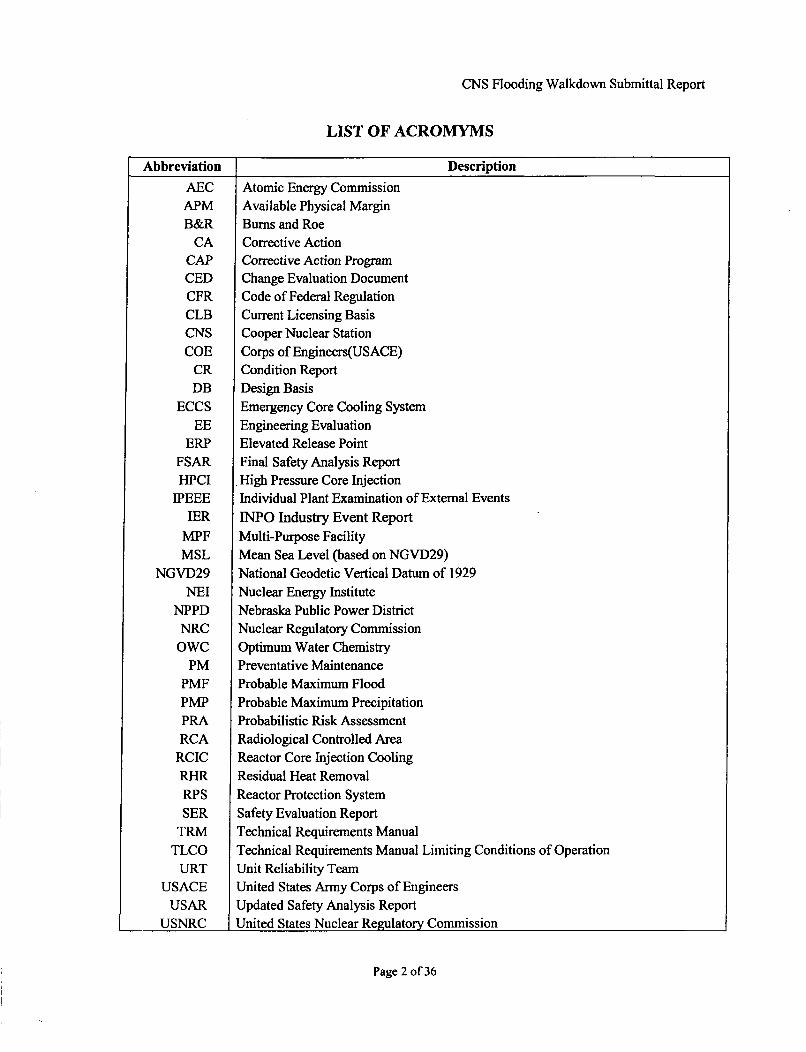
LIST OF ACROMYMS
Abbreviation Description
AEC Atomic Energy CommissionAPM Available Physical MarginB&R Burns and Roe
CA Corrective ActionCAP Corrective Action ProgramCED Change Evaluation DocumentCFR Code of Federal RegulationCLB Current Licensing BasisCNS Cooper Nuclear StationCOE Corps of Engineers(USACE)
CR Condition ReportDB Design Basis
ECCS Emergency Core Cooling SystemEE Engineering Evaluation
ERP Elevated Release PointFSAR Final Safety Analysis ReportHPCI High Pressure Core Injection
IPEEE Individual Plant Examination of External EventsIER INPO Industry Event Report
MPF Multi-Purpose FacilityMSL Mean Sea Level (based on NGVD29)
NGVD29 National Geodetic Vertical Datum of 1929NEI Nuclear Energy Institute
NPPD Nebraska Public Power DistrictNRC Nuclear Regulatory Commission
OWC Optimum Water ChemistryPM Preventative Maintenance
PMF Probable Maximum FloodPMP Probable Maximum PrecipitationPRA Probabilistic Risk AssessmentRCA Radiological Controlled Area
RCIC Reactor Core Injection CoolingRHR Residual Heat RemovalRPS Reactor Protection SystemSER Safety Evaluation Report
TRM Technical Requirements ManualTLCO Technical Requirements Manual Limiting Conditions of Operation
URT Unit Reliability TeamUSACE United States Army Corps of Engineers
USAR Updated Safety Analysis ReportUSNRC United States Nuclear Regulatory Commission
Page 2 of 36

CNS Flooding Walkdown Submittal Report
TABLE OF CONTENTS
SCOPE AND OBJECTIVE ............................................................................................ 5
2 DESIGN BASIS FLOOD HAZARD LEVEL ............................................................... 6
2.1 Probable Maximum Flood (PMF) .......................................................................... 6
2.2 Postulated Dam Failure .......................................................................................... 6
2.3 Probable Maximum Precipitation (PMP) ............................................................... 7
2.4 Other Evaluated Flooding Events .......................................................................... 8
2.5 Original Supporting Evaluations and Methodology ............................................. 8
2.6 Other Analysis and Evaluations ............................................................................ 9
2.7 CLB Flooding Summary Table ............................................................................. 11
3 EXTERNAL FLOOD PROTECTION AND MITIGATION FEATURES ................. 12
3.1 Flood Licensing Basis and Protected SSCs ........................................................ 12
3.2 Plant Operation During Flooding ........................................................................ 13
3.3 Flood D uration .................................................................................................... 14
3.4 Flood Protection Features ..................................................................................... 15
3.5 Procedures ................................................................................................................ 16
3.6 Adverse Weather Conditions .............................................................................. 17
3.7 Groundwater Ingress .......................................................................................... 17
4 INTERNAL WARNING SYSTEMS ..................................... 18
5 EFFECTIVENESS OF FLOOD PROTECTION SYSTEMS ...................................... 22
5.1 A cceptance Criteria .............................................................................................. 22
5.2 Overall Effectiveness of Plant Flood Protection Features .................................. 23
5.3 Other Existing Plant SSCs and Procedures that May Provide Flood Mitigation ..... 23
6 IMPLEMENTATION OF WALKDOWNS ................................................................. 24
6.1 Walkdown Package Development ..................................................................... 24
6.2 Team O rganization .............................................................................................. 24
6.3 Training A pproach ............................................................................................. 25
6.4 Peer Review Process ........................................................................................... 25
7 WALKDOWN RESULTS ........................................................................................... 26
7.1 Incorporated or Exterior Passive Features .......................................................... 26
7.2 Incorporated or Exterior Active Features ............................................................ 27
7.3 Temporary Passive Features ................................................................................ 27
7.4 Temporary Active Features ................................................................................ 27
Page 3 of 36

CNS Flooding Walkdown Submittal Report
7.5 Procedural Review .............................................................................................. 28
7.6 Inaccessible Features ........................................................................................... 29
7.7 Deficient Features ................................................................................................ 29
7.8 D elayed Inspection Features ............................................................................... 32
8 AVAILABLE PHY SICA L M A RG IN .......................................................................... 33
9 NEW FLOOD PROTECTION SY STEM S ................................................................. 34
10 REFEREN CES ................................................................................................................. 35
10.1 Regulatory Docum ents, Codes and Guidance .................................................... 35
10.2 NPPD Docum ents ................................................................................................ 35
Page 4 of 36

CNS Flooding Walkdown Submittal Report
1 SCOPE AND OBJECTIVEThis Flooding Walkdown Report is prepared in accordance with the request from the U.S.Nuclear Regulatory Commission as defined in the Recommendation 2.3, Flooding, Enclosure 4of the 50.54(f) Letter dated March 12, 2012.
In response to the nuclear fuel damage at Fukushima Daiichi due to earthquake and subsequenttsunami, the United States Nuclear Regulatory Commission (NRC) is requesting informationpursuant to Title 10 of the Code of Federal Regulations, Section 50.54 (f). As part of thisrequest, CNS was required to perform walkdowns to verify that plant features credited in thecurrent licensing basis (CLB) for protection and mitigation from external flood events isavailable, functional, and properly maintained. In addition, the purpose of the walkdowns was toidentify and address plant-specific degraded, non-conforming, or unanalyzed conditions (throughthe corrective action program) and associated APM (Available Physical Margin) and verify theadequacy of monitoring and maintenance procedures.
This information obtained and presented in this report is in accordance with NEI 12-07,"Guidelines for Verification Walkdowns of Plant Flood Protection Features" (Ref. 10.1.2) withno exceptions to the guidance. The scope of the report is further described in the subsequentsections of this document.
Page 5 of 36

CNS Flooding Walkdown Submittal Report
2 DESIGN BASIS FLOOD HAZARD LEVELThe CNS USAR (Ref. 10.2.2) Vol. II, Station Site and Environs, Hydrology Section 4.2.2.1states that the maximum river level established by studies by the Corps of Engineers was at899 ft MSL during the flood of record in 1952 prior to the installation of the upstream rivercontrols. The USAR projected upper limit of elevation for a 1,000-year flood discharge is900 ft MSL and for a 10,000-year flood discharge is 902 ft MSL.
2.1 Probable Maximum Flood (PMF)The CNS USAR Section 4.2.2.1 states "....The Probable Maximum Flood (PMF) isestablished at 903 feet MSL with a projected return frequency estimated to be in excess of1,000,000 years. The PMF is derived by centering a probable maximum rainstorm criticallyover the drainage area above Brownville. The Corps of Engineers has estimated that thepeak discharge for the PMF is 600, 000 cubic feet per second. This estimate is based on aqualitative judgment that the peak of a PMF event should be between two to three times thepeak of a standard projectflood. Preliminary estimates of standard project conditions on theMissouri and Platte Rivers were used in estimating the probable maximum flood peak of600, 000 cfs at CNS. "
CNS USAR Vol. II - Section 4.2.2.2 states; " the station site grade level of903feet MSLhas been raised 13feet above the natural grade level of 890 feet MSL, in order to bringfinalgrade one foot above the existing 902 feet MSL levee constructed by the Corps of Engineers.This levee was raised above its original design level and presently has a three foot minimumfree board over the 1952flood of record (899feet MSL). Flooding of the station isconsidered to be extremely unlikely due to the combination of upstream Missouri River floodcontrol and the high final site grade. With respect to the 1,000 year, 10,000 year and1,000,000 year (PMF) floods, these water levels will provide 3 /2feet, 1½2feet, and 6 inchesoffreeboard respectively below the 903'6" grade floor elevation of the principlestructures....... "
.. .... The wave action discussed within Subsection 4.2.2.1 (6.7feet on a smooth vertical walland 4.8feet on a riprapped slope), in conjunction with a PMF will not affect the plant propersince the nearest building is located about 200feet from the river edge and is surrounded bygrade to elevation 903'-0". Wave energy would be dissipated before reaching any of the mainbuildings. Wave action at the Intake Structure will not affect the safe shutdown of the plantsince the Service Water pumps and controls are protected by massive reinforced concretewalls and slab up to elevation 919"-0" ...... "
".... The Atomic Energy Commission (AEC) staff independently evaluated the floodingpotential at CNS. They estimated PMF to be 901.2feet MSL, which concurrent with windeffects would result in a maximum water level on the outside of the Intake Structure at 909.2feet MSL (PMF plus wave effects) and 905 feet MSL (PMF plus surge effects) on otherexposed safety related structures. The AEC staff required protection of safety relatedstructures and systems against these levels in order to ensure the capability to place andmaintain the plant in a safe shutdown under the flooding conditions described above....
2.2 Postulated Dam Failure
CNS USAR Section 4.2.2.1 states ". The failure of a large upstream dam is notconsidered probable. These dams are massive earth structures with impervious core walls,
Page 6 of 36

CNS Flooding Walkdown Submittal Report
large freeboard for wave action, and adequate spillways. The dams are located in a zone oflow seismic activity. The Gavins Point Dam, closest to the site is over 275 miles upstream. Itis approximately 8,100feet long with a height of 74 feet. It is 35feet wide at the top and upto 850feet wide at the base. The top of the dam is at 1,234feet MSL with a water level of1,205 feet MSL indicating a freeboard of29 feet. Its storage capacity is approximately500, 000 acre feet. These dams are under constant inspection by local Corps of Engineerspersonnel and are inspected once a year by a team ofprofessionals. If seismic failureoccurred in spite of these circumstances, the failure would most probably be other thaninstantaneous failure of a major portion of the dam. Under these circumstances, overtoppingof Gavins Point Dam, although conceivable, is not likely to occur.
....... The 901.2foot MSL water surface elevation and the 905foot MSL (PMF plus surgeeffects for safety related structures other than the Intake Structure) estimated by the AECstaff are below the 906foot MSL projected for the unlikely combination of an upstream damfailure concurrent with the maximum natural flood .... "
2.3 Probable Maximum Precipitation (PMP)CNS USAR Vol. II - Section 3.0 Meteorology, Sub-Section 3.1.3 Precipitation states
....... U.S. Department of Commerce - Weather Bureau and U.S. Department ofArmy Corpsof Engineers, Hydrometeorological Report No. 33 dated April, 1956, from which it wasdetermined that the "probable maximum precipitation "for the site area, 23.5 inches totalrainfall for a 24-hour period. This value has been determined from Figure 17 (August) of theaforementioned report. Converting this value to a rate equivalent to a one-hour rainfall, byusing the Civil Engineering Bulletin No. 52-8, revised March, 1965, published by theDepartment of the Army, office of the Chief of Engineers which determines a rainfall rate perhour from a 24-hour period, the "probable maximum precipitation "for the site area wasconservatively determined to be 3.56 inches per hour for a ten year return period.... "
In addition, CNS USAR Vol. II - Section 3.0 Meteorological Design Bases, sub-section 3.2.3Precipitation states; "....... Class land Class II buildings are protected from the effects ofprecipitation through the use of roof drains and overflow scuppers. The Reactor Building,Diesel Generator Building, and Control Building use 4 inch roof drains and 6 inch scuppers.Using the discharge rates in drains provided in the 1971 issue of the National StandardPlumbing Code, with fullflow from the vented systems, the roof drainage and overflowcapacity from these buildings can sustain a rainfall rate of over 10 inches of water per hour.The roof drains are designed to eventually be carried through underground piping into theMissouri River. The remaining local site drainage is designed such that any excess rainfallnot immediately absorbed into the ground will flow away from the buildings to be dischargedinto drywells or low lying areas adjacent to the plant site. Accordingly, these designs cansafely remove the accumulated water from the probable maximum precipitation ratedescribed in Section 11-3.1.3, and can also accommodate the AEC 's estimated 9.7 in./hr inone hour rainfall rate without adverse effects on the safety-related systems necessary for safeshutdown. "
Page 7 of 36

CNS Flooding Walkdown Submittal Report
2.4 Other Evaluated Flooding EventsThe CNS USAR and associated original FSAR question responses evaluated several otherflooding events which were concluded as bounded by the establish PMF. These included:
Ice Blockage or Damming - The USAR Section 4.2.2.1 states" ... .Flooding caused byice blockage is considered credible only at river levels significantly lower than the PMF.Flooding caused by ice blockage would cause water surface elevations below those of thePMF. "
> River Diversion Due to Flooding - USAR Vol. II, Section 4.2.3.2 states; "...afailure ofthe Oahe or Ft. Randall flood control dams is the most likely initiator of a riverdiversion. The closer of the two, Fort Randall, is almost 350 miles upstream from theplant site and there would be a three day warning before the river reaches a peak floodstage at CNS. During this peak flood stage, shutdown procedures to the reactor couldbegin and continue as the flood waters slowly recede. After the river diversion occurs, theresulting isolated body of water in the vicinity of the site, fed by ground water inflow,would retain essentially the same stage characteristics that apply to the present openriver as long as the main channel was retained in the existing valley. Minor variationsresulting from elimination of some bends would be of no consequence to the safeoperation of the plant. Extreme low water stages which might be attained in the naturalchannel would not occur under these circumstances because of the lag in response ofgroundwater to short term changes in the river channel. It is concluded, therefore, thatthere would be an adequate supply of water to effect a safe shutdown of the plant."
2.5 Original Supporting Evaluations and MethodologyVarious supporting analysis and evaluations were performed during development of theoriginal FSAR and follow up responses to original AEC review questions throughamendment.
Corps of Engineers Study - According to FSAR Question No. 2.1 (Ref. 10.2.3) theUSACE estimated a Probable Maximum Flood (PMF) elevation between 902-ft and903-ft Mean Sea Level (MSL), in practice CNS typically regards 903-ft MSL as its PMFvalue. The USACE also calculated wave heights occurring coincident with the 903-ftMSL PMF event. It estimated a shallow water "significant wave height" of 4-ft, a"one-percent wave height" of 6.7-ft, and the "wave run-up" against a vertical wall (IntakeStructure) of 6.7-ft. The calculation used a wind speed of 45 mph as prescribed by theNRC in FSAR Question No. 2.2 (Ref. 10.2.3). The response to FSAR Question No. 2.2noted that the relationships used to estimate these wave heights were derived from studiesmade on lakes and oceans, and that it is not believed that waves of this magnitude couldbe generated in a river flood setting. The FSAR Question No. 2.2 response noted thatwaves could only impact the intake structure, with the run-up reaching an elevation of909.7 ft MSL. The response states that wave energy would be dissipated before reachingthe other Class I Buildings (Main Building Complex). The Main Building Complex isapproximately 200' away from the river channel edge, with the surrounding gradeelevated to 903 +/- ft MSL.
The USACE had reported (stated in CNS USAR Section 4.2.2.2) that a major dam breakcoincident with a PMF event was not credible; however, a maximum flow rate for a dam
Page 8 of 36

CNS Flooding Walkdown Submittal Report
break event and resulting surface water elevation was estimated. As described in theUSAR, the maximum natural flood combined with a "...failure of a major flood controldam - either Oahe or Fort Randall" could produce river flows of 1,250,000 cfs. A watersurface elevation based on this flow rate was predicted to reach elevation 906 ft MSL.The evaluation did not consider wave action coincident with a 906 ft MSL flood event.
Atomic Energy Commission Study - As previously outlined in the USAR Sectionabove, the Atomic Energy Commission reported in the Safety Evaluation Report (SER)(Ref. 10.2.7) that its conservative estimation of the PMF Elevation at CNS was 901.2 ftMSL, based on a River flow rate of 1,000,000 cfs. AEC calculated coincident wave crestscould reach an elevation of 909.2 ft MSL at the intake structure, and 905 ft MSL at theother structures across the site (located away from the river channel). The AEC alsoconcluded that seismically induced dam failure coincident with a PMF is not credible butdid consider a dam break concurrent with a 2 PMF event. Their results indicated that theresulting flood elevation was lower than the PMF event alone.
2.6 Other Analysis and Evaluations
IPEEE -Individual Plant Examination of External Events
In 1991, in accordance with 1OCFR50.54(f), the NRC issued Generic Letter 88-20,Supplement 4 based on staff and industry experience with plant-specific probabilistic riskassessments (PRAs), that systematic examinations are beneficial in identifying plant-specific vulnerabilities to severe accidents which could be fixed with low-costimprovements. The supplement was focused on external events that could be significantcontributors to core damage in some instances. Section 5 of the CNS IPEEE report (Ref.10.2.9) submitted to the NRC addresses the occurrence of high winds, floods, and otherweather related events with regard to probability of beyond design basis effects.
Potential Dam Failures - This section of the report states" The location of theupstream dams are listed together with their river mile in Table 5.8. Section 11-4.2.1of the CNS USAR provides a discussion of dam failure scenarios. An analysis of theFort Randall Dam failure showed that waters released would require at least fourdays to reach the CNS site. If this event occurs, river elevations of 904 feet MSLwould be expected, a maximum of 0.5 ft above the ground floor elevation of 903.5 feetMSL. An emergency procedure is in place to install sandbags and wood planks tocombat the flood. Such actions are effective to protect the plant to water levels up to907. 6'. The procedure was successfully implemented at CNS during the flood in1993. As such there is confidence in the ability of the plant staff and personnel tomitigate the flood event. The elevation of 906 feet MSL is calculated by postulating adam failure concurrent with the maximum natural flood. The effects of windgenerated wave action in the determination of the water level at the plant site werenot considered.
This is acceptable from previous discussions on the wave height development whichconcluded that wave height would substantially dissipate prior to reaching the plantstructures.
Failure of the Oahe Dam upstream from the Fort Randall Dam is discussed inNUREG/CR-4767. According to a recent study, the US. Army Corps of Engineers
Page 9 of 36

CNS Flooding Walkdown Submittal Report
has estimated that a peak-water surface elevation of 922 feet MSL (18.5feet aboveground floor) will be reached if the Oahe Dam fails. It would take approximately 3.5days for the first floodwave resulting from the dam failure to reach CNS.
NUREG/CR-4767 based the failure frequency estimate for the Oahe Dam onhistorical data for internalfailures of earth dams. Studies suggested that earth damsfail due to internal events with afrequency from 1. OE-OS/yr to 1.OE-04/yr. TheNUREG analyses used 5. OE-05 per year as a best estimate. The District reviewed thesupporting COE analyses and noted that a 100 year return frequency flood event atthe Oahe dam site was assumed coincident with dam failure. Assuming that theseindependent events would have to occur during the same seven day period and basedon the conclusion that core damage would result from a flood to elevation 922feetMSL, the contribution to core damage frequency due to the Oahe Dam failure wasestimated as 9. OE-09/yr.
In the NUREG estimate it was conservatively assumed that the dam was completelyfull at the time of the failure (concurrent with a spillway design flood) and that thedam was assumed to fail catastrophically. These two assumptions are very unlikely.Additionally, the Oahe Dam and reservoir level is closely managed by the COE.Therefore, it isjudged that this event can be screened per NUREG-1407 and nofurther actions to reduce the CNS vulnerability to the Oahe Dam failure arewarranted.... "
NPPD Calculation NEDC 11-076In preparation for the NRC 50.54(f) response, CNS has directly developed and/orcontracted the services of vendors to perform various evaluations and analysis of currentpotential flooding impact on the plant. These analyses do not change the plant's CLB butserve to provide significant information in support of the established PMF going forward.
Calculation NEDC 11-076 (Ref. 10.2.11) was developed for informational use only, toevaluate issues regarding CNS external flooding eventsas initiated by and described incondition report CR-CNS-2010- 01630. It was also utilized in the disposition of the CR'sassociated corrective actions CA-6, CA-8, CA-10, and CA- 11. The calculation evaluatedagainst the hydraulic (i.e. stage discharge) of three scenarios including (1) an estimated500-year event based on the peak flow reported in the Corps of Engineers 2004 UpperMississippi Flood Frequency Study, (2) the Probable Maximum Flood event establishedin the CNS USAR, and (3) a Ft. Randall Dam Break Event at the Maximum High PoolCondition as provided by the Corps of Engineers. The calculation assumes that no leveesfailed during each flood scenario considered. CNS grade is elevated above the tops ofadjacent levees, a conservative assumption in terms of maximum flood height (muchlarger flood area would be available behind the levees resulting in a lower flood level).
The calculation concluded that the predicted stage of the Missouri River estimated in thecalculation compared favorably with the river stages determined during the stationsoriginal design. It was concluded that the river stage (water level) discussed in the USARremains a conservative estimate for the flow scenarios considered with respect to thismethodology. However, the flow scenarios themselves, while not discounted, could notbe verified. A new PMF hydrologic study using current methodology was recommended
Page 10 of 36

CNS Flooding Walkdown Submittal Report
and is currently being performed in response to Recommendation 2.1, Flooding enclosureof the 50.54(f) Letter. This effort will also include reevaluation of the current sitedrainage when subjected to a PMP event. The PMP study is due to be completed beforethe end-of-year.
2.7 CLB Flooding Summary TableThe below table summarizes the CNS CLB based upon the information as presented in thisreport.
CONDITION CNS CLB COMMENTS.
PMF Peak Flow Rate' 600,000 CFS PMP Event centered above Brownville, NEPMF Still Water Plant site elevated 903 +/- ft MSL. First Floor of all ClassSurface Elevation 903 ft MSL' I building at 903.5 ft MSL.
Flood Barriers not needed at intake since criticalPMF + Wave Run Up equipment is elevated above 906 ft and protected from
at Intake Structure 909.7 ft MSL wave impacts.Class I buildings grade level openings at 903.5 ft MSL,
PMF + Wave Action Protected by Flood Barriers from standing water toMain Plant Complex No Impact elevation 906 ft
Notes:I. The USACE estimated a higher river stage during the PMF than the AEC, despite the fact it used a
lower flow rate (600,000 cfs vs. 1,000,000 cfs). Details of the methodology utilized by the AEC todevelop its stage-flow relationship were not described, except for a statement in the SER text that theAEC constructed an "Analytical Model". The analysis conducted by CNS in 2011 is consistent withthe USACE estimates stage-discharge estimates - see NEDC 11-076 (Ref. 10.2.11).
2. This elevation is based on a steady flow Rate of 600,000 cfs
3. This elevation is based on a peak flow rate of 1,000,000 cfs.
Therefore in summary, the Current Licensing Basis as stated in the CNS USAR provides fora value of 903.0 MSL for the Maximum Probable Flood.
Page 11 of 36

CNS Flooding Walkdown Submittal Report
3 EXTERNAL FLOOD PROTECTION AND MITIGATION FEATURES
3.1 Flood Licensing Basis and Protected SSCsThe general ground elevation surrounding CNS Class I Structures is elevated 13-ft above thenatural floodplain to 903 ft MSL. The finished floor elevation of all Class I Structures isplaced at elevation 903.5 ft MSL, or 1/2 ft above the PMF event. These structures weredesigned for a hydraulic load equivalent to a groundwater elevation of 903-ft and reviewedfor integrity for a river elevation up to 906 ft MSL. Grade level openings on exterior walls ofthe buildings (except for the intake structure) are protected from wave effects and watersurface elevations up to 906 ft MSL with flood barriers erected per CNS Procedure 7.0.11(Ref. 10.2.14) and 5.1 Flood (Ref. 10.2.13).
The following CNS safety-related plant structures have been identified as protected fromflooding as noted:
Intake Structure - As stated in the USAR; the service water motors and controls in the IntakeStructure are located above elevation 908-ft MSL. These motors and controls are protectedfrom the predicted wave effects by 24-in thick concrete walls extending up to elevation919-ft MSL. The Intake Structure need not be isolated due to the fact that there is no essentialequipment located there at or below 906 ft MSL that will be adversely affected inperformance of a safe shutdown function in the event of flooding.
Reactor Building - Protected from wave effects and flood water by grade level building wallsand by temporary flood barriers to elevation 906 ft MSL
Emergency Diesel Generator Building - Protected from wave effects and flood water bygrade level building walls and by temporary flood barriers to elevation 906 ft MSL
Radwaste Building - Protected from wave effects and flood water by grade level buildingwalls and by temporary flood barriers to elevation 906 ft MSL
Control Building - Protected from wave effects and flood water by grade level building wallsand by temporary flood barriers to elevation 906 ft MSL
Controlled Corridor - Protected from flood water by grade level Reactor and TurbineBuilding walls to elevation 906 ft MSL
Turbine Building - Protected from wave effects and flood water by grade level building wallsand by temporary flood barriers to elevation 906 ft MSL
Z-Sump (Below ERP Tower) - As stated in the USAR; the top of floor drain sump Z, at thebase of the Elevated Release Point tower, is located at 891 ft MSL and therefore is withinpostulated flood levels. The Z Sump contains equipment essential to the operation of SGTS(Standby Gas Treatment System), and therefore the sump must remain functional wheneverSecondary Containment is required. Although the ground elevation at the sump is only 890 ftMSL, the Z Sump will not be affected by flooding since the sump penetrations are sealed andthe proper functioning of the sump is monitored when flood levels reach 890 ft MSL.
Diesel Fuel Storage Tanks - As stated in the USAR; there is sufficient fuel in the Diesel OilStorage Tanks to assure seven days of operation of a single diesel generator powering asingle critical division of safe shutdown loads. This time duration is sufficient to obtain more
Page 12 of 36

CNS Flooding Walkdown Submittal Report
fuel, if needed. The two storage tanks are buried and their appendages are protected by asubstantial cover. The manholes providing access to the Diesel Oil Transfer Pumps, thecapped fill connections and the tank vents are all located above 906 ft MSL. The design andinstallation of the tanks assure flotation does not occur when empty during the PMF.
The following CNS plant structures have been identified as important to the protection of thevarious safety-related structures and equipment and are also protected from flooding asnoted:
Augmented Radwaste Building - Protected from wave effects and flood water by grade levelbuilding walls and by temporary flood barriers to elevation 906 ft MSL
Boiler Room - Protected from wave effects and flood water by grade level buildingfoundation walls and by temporary flood barriers to elevation 906 ft MSL
Fan Room - Protected from wave effects and flood water by grade level building foundationwalls and by temporary flood barriers to elevation 906 ft MSL
Water Treatment Plant - Protected from wave effects and flood water by grade level buildingfoundation walls and by temporary flood barriers to elevation 906 ft MSL
Tool Crib - Protected from wave effects and flood water by grade level building foundationwalls and by temporary flood barriers to elevation 906 ft MSL
Machine Shop - Protected from wave effects and flood water by grade level buildingfoundation walls and by temporary flood barriers to elevation 906 ft MSL
MPF Building - Protected from wave effects and flood water by grade level buildingfoundation walls and by temporary flood barriers to elevation 906 ft MSL
Other Site Structures - Various site out buildings and structures classified as not important tosafe operation and shutdown of the plant are located at base elevations lower than the PMFelevation of 903 ft MSL. CNS Procedure 5.1 FLOOD, evaluation of the protection theseassets is determined by NPPD plant management by implementing actions based on variousparameters including; plant safety, asset value, importance to overall long term powergeneration, etc.
3.2 Plant Operation During FloodingThe operation of the plant based on a forecasted or eminent flooding event is addressed byCNS TRM (Technical Requirements Manual) Section T 3.7 Plant Systems, sub-sectionT3.7.1 River Level, limiting condition of operation TLCO 3.7.1. TLCO 3.7.1 states, "TheRiver Level shall be < 895 ft MSL and not forecast to be> 902 ft MSL" at all times.
Page 13 of 36

CNS Flooding Walkdown Submittal Report
The conditions are set as follows:
CONDITION REQUIRED ACTION COMPLETION TIME
A. River level is > 895 ft MSL A. 1 Implement CNS Site Flood ImmediatelyProcedure 5.1 FLOOD
B. River Level is > 902 ft MSL B. 1 Implement CNS Site Flood Immediatelyor forecast Ž_ 902 ft MSL Procedure 5.1 FLOOD.within the next 36 hours.
AND
B.2 Be in MODE 3 (Hot 12 hours
Shutdown)
AND
B.3 Be in MODE 4 (Cold 36 hoursShutdown)
The TRM BASES states:
The river level of the Missouri River is controlled by the U.S. Army Corps of Engineersusing dams. The closest upstream major flood control dam is approximately 350 milesupstream. The use of these dams reduces the possibility of a site flood. However, should adam break or in case of a river level of 895 ft MSL, the CNS Site Flood Procedure will beput into effect.
Should the level reach 902 ft MSL or a forecast issued by the official government agencyindicates expected levels of 902 ft MSL or greater within the next 36 hours, the reactor willbe shutdown and vented to atmosphere.
A plant shutdown is initiated under any of the following conditions:
1. Floodwaters either reach 902 ft MSL, or are forecast to reach 902 ft MSL within the next36 hours (as from the 10,000 year flood or an upstream dam failure).
2. Floodwater accumulates in either Diesel Generator Room, any of the four ReactorBuilding Quads, or the Control Building Basement.
3. Plant conditions warrant reactor to be shut down.
3.3 Flood DurationThere is no specifically stated time(s) associated with the PMF event provided within theCNS CLB. CNS USAR Figure 11-4-7, Platte Plus Missouri River (s) Hydrograph, displaysthe projected river discharge at Cooper Nuclear Station for the PMF in Time in Days versusCFS. Inspection of the hydrograph indicates an approximate duration of 5 ½2 days of floodconditions may be expected from a river flow of 200,000 CFS peaking to 600,000 CFS andback down to 200,000 CFS. Initial inspection of USAR Figure 11-4-8, Estimated StageDischarge Relation Missouri River at Brownville Nebraska, would correlate to an
Page 14 of 36

CNS Flooding Walkdown Submittal Report
approximate minimum flood level of 895 ft MSL to the maximum projected PMF value atCNS.
3.4 Flood Protection FeaturesVarious methods of protection are specifically detailed within the CNS USAR Section4.2.2.2 as to the plant's response to an imminent flooding event. The USAR states thatmaterial and equipment necessary to perform these protective measures are available at CNSand inventoried on an annual basis. As an example; special equipment includes; two portablegasoline powered pumps and 100 ft minimum (per pump) of 2 ½/2-inch non-collapsible hose.
The CNS USAR specifically addresses various actions that will be taken to protect safetyrelated SSCs located below the PMF plus wave effects level of 905 ft MSL. The originalresponse to FSAR Question 2.34, Amendment 17 (Ref. 10.2.5) identified specific equipmentand components to be protected including the:
" RHR Service Water Booster pumps located at Elevation 882'-6" MSL in the ControlBuilding basement.
" RHR pumps 1A and IC in the northwest quadrant room of the Reactor Building atElevation 859-'9" MSL.
" RHR pumps 113 and ID in the southwest quadrant room of the Reactor building atElevation 859-'9" MSL.
• RCIC turbine pump set in the northeast quadrant room of the Reactor building atElevation 859-'9" MSL.
" Diesel generator water tight junction boxes at Elevation 904' MSL.* D.C. switchgear and battery chargers in Control Building 903'-6" level at less than 905'
MSL.• ECCS system logic panels on the Control Building 903'-6" level at less than 905' MSL.• RPS M-G set at the 903'-6" level of the Control Building.
Building FeaturesA comprehensive review of all potential CNS external flood barriers and features asoriginally defined in Regulatory Guide 1.102 (Ref. 10. 1.3) was performed by reviewing allavailable plant drawings and documentation and performing initial walk downs of allaccessible plant areas. These barriers/features include the permanent flood protectionprovided by the structural walls, penetrations, doors, hatches, water-stops incorporated in theconstruction of the penetrations and construction joints, special rubber boots, and otherrelated barriers. Temporary flood protection, such as sand bagging, stop logs for specificareas and openings as needed were also included.
The following is a breakdown by area of the number of flood barriers/features identifiedduring the development of the features database contained in the Flood Walkdown CNSDED Correspondence 12-0002 (Ref. 10.2.19) and confirmed by the formal feature walkdownprocess:
" Turbine Building - 22 Exterior building walls and 76 piping and conduit penetrations" Radwaste Building - 11 Exterior building walls and 32 piping and conduit penetrations
Page 15 of 36

CNS Flooding Walkdown Submittal Report
* Augmented Radwaste Building - 13 Exterior building walls and 27 piping and conduitpenetrations
* Reactor Building - 12 Exterior building walls and 15 piping and conduit penetrations" Control Building - 9 Exterior building walls and 65 piping and conduit penetrations* Machine Shop - 2 Exterior building walls and 6 piping and conduit penetrations" Water Treatment Building - 2 Exterior building walls and 23 piping and conduit
penetrations" Exhaust Fan Room - 2 Exterior building walls and 2 piping penetrations* Heating Boiler Room- 1 Exterior building walls and 8 piping penetrations" Emergency Diesel Generator Rooms - 8 Exterior building walls and 31 conduit
penetrations" Intake Structure - 4 Building walls* Site:
> Manholes - 9 conduit penetrations> Z Sump - I conduit penetration
" Temporary Features:> Exterior barrier walls/stop logs - 44
" Site Drainage System:> Dry Wells- II> Catch Basins - 7> Area Inlets - 20
3.5 ProceduresCNS has established two primary procedures for guidance in the station's response to anexternal flooding event.
5. IFLOOD - This is the primary procedure used for response to river level increase and isentered at a rising river level of greater than or equal to 895 ft MSL, notification of upstreamdam failure and/or the river level is forecast to rise above a greater than or equal to value of902 ft MSL within the next 36 hours. The procedure invokes numerous flood responsemeasures and activities in addition to the other main response procedure 7.0.11 FloodControl Barriers (Ref. 10.2.14) which directs the CNS Maintenance department in theinstallation of temporary flood control barriers and features.
This procedure requires specific review during formal Flooding Walkdown Inspectionsperformed in accordance with NEI 12-07 activities to evaluate the practicality of theassociated actions performed by site personnel with regard to response timing and equipmentstaging and implementation.
7.0.11, FLOOD CONTROL BARRIERS - As mentioned previously this MaintenanceProcedure directs the CNS maintenance personnel in the installation of temporary floodcontrol barriers and features. The procedure provides a system of primary barriers at theopenings of the outside walls of the main buildings complex to seal the buildings up toelevation 906 ft MSL. Secondary barriers are provided strategically inside the buildings to
Page 16 of 36

CNS Flooding Walkdown Submittal Report
control any minor leakage past the primary barriers and to break the building complex upinto small areas that can be more easily protected.
3.6 Adverse Weather ConditionsEmergency Procedure 5.1FLOOD and other supporting procedures and documents do notspecifically address the intensity of potential adverse weather conditions on the execution ordeployment of external flood mitigation activities. The procedures do however provide forthe assessment of the severity of conditions which may lead to immediate actions to bring theplant to cold shutdown in a timely manner.
Adverse weather is not an aspect of CNS site design basis. The worst expected weatherwould be heavy rainfall which will not be a hindrance to stop log barrier construction.These activities are well established and practiced using procedures and standard physicalmeasures (addressed further in Section 7.5) that can be implemented based on their simplisticnature and design.
3.7 Groundwater IngressThe CNS CLB does not specifically address or quantify ground water inleakage from the sitesubsurface water table. Groundwater level is monitored/logged once per shift based on levelindication located within site well(s) providing plant water supply. According to CNS OPSpersonnel, site groundwater level normally fluctuates between 875' MSL to 885' MSL withthe highest recorded level of 900.8' during the 2011 May flooding event.
USAR Section XII-2.4.4.2 (Ref. 10.2.20) Design Considerations, Statement 5 second to lastparagraph states, ".... Where penetrations enter buildings through sleeves; details relating tothe methods of waterproofing and maintaining building integrity have been developed.".
The above statement is based on CNS original response to FSAR Question/Answer 12.2Amendment #9 (Ref. 10.2.2 1) which states, "........Membrane waterproofing material usedon the exterior foundation walls of the Reactor, Turbine, Control and Radwaste Buildings isthe same as described in the answer to Question 12.1 with the exception that integrallymolded protrusions were used to obtain a cast-in-place barrier with the concrete foundationwall. This barrier was sealed at the top just below grade into a reglet, and at the bottom wassealed to the mat material by the same adhesives and tape strips outlined in the answer toQuestion 12.1. With respect to in-service inspection of the vertical waterproofing barrier thesame controlled application as described in the answer to Question 12.1 is applicable, exceptthat the 2 inch protective cover has been deleted. Therefore, no provisions have been madeto check the integrity of the membrane during the life of the plant. Drains are provided inthe base slab of all buildings to collect any water which may accumulate on the slab for anyrea so n ........................................................................................................................................Where penetrations enter buildings through sleeves, details relating to the methods ofwaterproofing and maintaining building integrity have been developed and are shown inFigure 12.2-1. "
(Note: Figure 12.2-1 is CNS B & R Drawing 2299 (Ref. 10.2.22).)
Page 17 of 36

CNS Flooding Walkdown Submittal Report
4 INTERNAL WARNING SYSTEMSCurrently there are no official plant internal warning systems dedicated specifically todetection of water infiltration related to an External Flooding Event in the current licensingbasis. However various level alarms are provided for sumps, low building elevations andyard manholes which provide annunciation in the CNS Control Room (Panel B-3 and S-1annunciator windows). These include the following: (Note: All reactor building and turbinebuilding sumps are HI-HI alarms which signal the control room at the setpoint when onepump is overloaded and will concurrently call the second pump into service)
Reactor Building Sumps - EL. 859'-9"
Sump 1-A: is located in the RHR Pump Room in northwest Quad of the Reactor Buildingat elevation 859'-9". The sump receives discharge from various plumbing fixtures andfloor drains located on multiple elevations of the Reactor Building, noted in CNSProcedure 2.2.27 "Equipment, Floor, and Chemical Drain System", Attachment A. Thesump contains dual sump pumps (1-SP- lA1 & 1-SP- 1A2) which controls sump waterlevel with discharge to the radioactive floor drain line (FDR-1). Setpoint is 34" of waterin the sumnp.
" Sump I-B: is located in the Core Spray Pump Room in northeast Quad of the ReactorBuilding at elevation 859'-9". The sump receives discharge from various plumbingfixtures and floor drains located on multiple elevations of the Reactor Building, noted inCNS Procedure 2.2.27 "Equipment, Floor, and Chemical Drain System", Attachment A.The sump contains dual sump pumps (l-SP- IBI & I-SP- 1B2) which controls sumpwater level with discharge to the radioactive floor drain line (FDR-1). Setpoint is 34" ofwater in the sump.
" Sump 1-C: is located in the RHR Pump Room in southeast Quad of the Reactor Buildingat elevation 859'-9". The sump receives discharge from various plumbing fixtures andfloor drains located on multiple elevations of the Reactor Building, noted in CNSProcedure 2.2.27 "Equipment, Floor, and Chemical Drain System", Attachment A. Thesump contains dual sump pumps (1-SP- ICI & l-SP- 1C2) which controls sump waterlevel with discharge to the radioactive floor drain line (FDR-1). Setpoint is 34" of waterin the sump.
" Sump l-D: is located in the Core Spray Pump Room in southeast Quad of the ReactorBuilding at elevation 859'-9". The sump receives discharge from various plumbingfixtures and floor drains located on multiple elevations of the Reactor Building, noted inCNS Procedure 2.2.27 "Equipment, Floor, and Chemical Drain System", Attachment A.The sump contains dual sump pumps (l-SP- IDI & l-SP- 1D2) which controls sumpwater level with discharge to the radioactive floor drain line (FDR-1). Setpoint is 34" ofwater in the sump.
Sump 1 -E: is located in the Core Spray Pump Room in southeast Quad of the ReactorBuilding at elevation 859'-9". The sump receives discharge from various plumbingfixtures and floor drains located on multiple elevations of the Reactor Building, noted inCNS Procedure 2.2.27 "Equipment, Floor, and Chemical Drain System", Attachment A.The sump contains dual sump pumps (l-SP- IEI & 1-SP- 1E2) which controls sumpwater level with discharge to the radioactive floor drain line (PW-1). Setpoint is 24" ofwater in the sump.
Page 18 of 36

CNS Flooding Walkdown Submittal Report
Turbine Building Sumps - Basement (EL. 882'-6")
Sump I M: is located in the northeast comer of the Turbine Generator Equipment Area atelevation 882'-6" in the bay between column lines 14-E and 14-F. The sump receivesdischarge from various plumbing fixtures and floor drains located on multiple elevationsof the Turbine Building, noted in CNS Procedure 2.2.27 "Equipment, Floor, andChemical Drain System", Attachment A. The sump contains dual sump pumps whichcontrols sump water level with discharge to the non-radioactive floor drain line (FDN- 1).Setpoint is at 3'6" of water in the sump.
* Sump I P: is located in the northwest comer of the Turbine Generator Equipment Area atelevation 882'-6" in the bay between column lines 14-F and 14-G. The sump receivesdischarge from various plumbing fixtures and floor drains located on multiple elevationsof the Turbine Building, noted in CNS Procedure 2.2.27 "Equipment, Floor, andChemical Drain System", Attachment A. The sump contains dual sump pumps whichcontrols sump water level with discharge to the radioactive floor drain line (PW-2).Setpoint is at 3'6" of water in the sump.
Sump 1Q: is located in the northeast comer of the Turbine Generator Equipment Area atelevation 882'-6" in the bay between column lines 14-E and 14-F. The sump receivesdischarge from various plumbing fixtures and floor drains located on multiple elevationsof the Turbine Building, noted in CNS Procedure 2.2.27 "Equipment, Floor, andChemical Drain System", Attachment A. The sump contains dual sump pumps whichcontrols sump water level with discharge to the radioactive floor drain line (FDR-2).Setpoint is at 3'6" of water in the sump.
" Sump IR: is located in the northeast comer of the Turbine Generator Equipment Area atelevation 882'-6" in the bay between column lines 14-C and 14-D. The sump receivesdischarge from various plumbing fixtures and floor drains located on multiple elevationsof the Turbine Building, noted in CNS Procedure 2.2.27 "Equipment, Floor, andChemical Drain System", Attachment A. The sump contains dual sump pumps whichcontrols sump water level with discharge to the radioactive floor drain line (FDR-2).Setpoint is at 3'6" of water in the sump.
* Sump 1 S: is located in the southwest comer of the Turbine Building Hold-upDecontamination & Sample Room at elevation 882'-6" in the bay between column lines7-G and 7-F. The sump receives discharge from various plumbing fixtures and floordrains located on multiple elevations of the Turbine Building , noted in CNS Procedure2.2.27 "Equipment, Floor, and Chemical Drain System", Attachment A. The sumpcontains dual sump pumps which controls sump water level with discharge to theradioactive floor drain line (FDR-2). Setpoint is at 3'6" of water in the sump.
" Sump I T: is located in the southwest comer of the Turbine Generator Equipment Area atelevation 882'-6" in the bay between column lines 7-C and 7-D. The sump receivesdischarge from various plumbing fixtures and floor drains located on multiple elevationsof the Turbine Building, noted in CNS Procedure 2.2.27 "Equipment, Floor, andChemical Drain System", Attachment A. The sump contains dual sump pumps whichcontrols sump water level with discharge to the radioactive floor drain line (PW-2).Setpoint is at 3'6" of water in the sump.
Page 19 of 36

CNS Flooding Walkdown Submittal Report
Sump IU: is located in the southeast comer of the Turbine Building Equipment Area atelevation 882'-6" in the bay between column lines 5-C and 6-C. The sump receivesdischarge from various plumbing fixtures and floor drains located on multiple elevationsof the Turbine Building, noted in CNS Procedure 2.2.27 "Equipment, Floor, andChemical Drain System", Attachment A. The sump contains dual sump pumps whichcontrols sump water level with discharge to the non-radioactive floor drain line (FDN-1).Setpoint is at 3'6" of water in the sump.
Sump IV: is located in the southeast comer of the Turbine Building Equipment Area atelevation 882'-6" in the bay between column lines 5-G and 6-G. The sump receivesdischarge from various plumbing fixtures and floor drains located on multiple elevationsof the Turbine Building, noted in CNS Procedure 2.2.27 "Equipment, Floor, andChemical Drain System", Attachment A. The sump contains dual sump pumps whichcontrols sump water level with discharge to the non-radioactive floor drain line (FDN-1).Setpoint is at 3'6" of water in the sump.
Diesel Building Sumps - EL. 903'-6"
Sump DG- 1: is located in the northeast comer of the Diesel Generator Equipment Roomat elevation 903'-6" in the bay between column lines 15.5-B and 15.5-B.4. The sumpreceives discharge from various plumbing fixtures and floor drains located on the mainfloor of the Diesel Generator Building. The sump contains a single sump pump whichcontrols sump water level with discharge to the non-radioactive floor drain line (FDN-1).Setpoint is at 30" of water in the sump.
Sump DG-2: is located in the northeast comer of the Diesel Generator Equipment Roomat elevation 903'-6" in the bay between column lines 12.8-B and 12.8-B.4. The sumpreceives discharge from various plumbing fixtures and floor drains located on the mainfloor of the Diesel Generator Building. The sump contains a single sump pump whichcontrols sump water level with discharge to the non-radioactive floor drain line (FDN- 1).Setpoint is at 30" of water in the sump.
Control Building Sumps - Basement (EL. 882'-6")
" Sump 1 L: is located in the northeast comer of the Emergency Condensate Storage Area atelevation 877'-6" in the bay between column lines 15.4-J.8 and 16.2-J.8. The sumpreceives discharge from various plumbing fixtures and floor drains located on multipleelevations of the Control Building, noted in CNS Procedure 2.2.27 "Equipment, Floor,and Chemical Drain System", Attachment A. The sump contains dual sump pumpswhich controls sump water level with discharge to the non-radioactive floor drain line(FDN-1). Setpoint is at 3'6" of water in the sump.
* Sump 1 X: Control Building Electrical Vault Sump is located in the southeast comer ofmanhole C2 sump of the Control Building at elevation 882'-6". The sump receivesdischarge from the adjacent electrical vaults (P2, C3, & P3). The sump contains a singlesump pump (l-X) which controls sump water level with normal discharge to the non-radioactive floor drain line (FDN-1). Setpoint is at 2' of water in the sump.
Page 20 of 36

CNS Flooding Walkdown Submittal Report
Yard Manhole Sumps -EL. 903'-6"
Sump 1 W: is located along the east side of the Diesel Generator Building at elevation903'-6". The sump is located at the base of electrical manhole C3 and receives dischargefrom the adjacent electrical manhole P3. The sump contains a single sump pump (I -W)which controls sump water level with normal discharge to the roof drain line (RD-2).Setpoint is at 2' of water in the sump.
Sump 1 Y: is located along the east side of the Diesel Generator Building at elevation903'-6". The sump is located at the base of electrical manhole C4 and receives dischargefrom the adjacent electrical manhole P4. The sump contains a single sump pump (l-Y)which controls sump water level with normal discharge to the roof drain line (RD-2).
Reactor Building Torus Area - EL. 859'-9"Level alarm / indication is located at the basement elevation of the Torus area to indicatewater accumulation. The alarm will sound in the control room when 4" have accumulated.
Control Building Level - Basement (EL. 882'-6")Level alarm / indication is located at the basement elevation of the Control Building toindicate water accumulation. Alarms are sent to the control room at 2", 5" and 8".
Z-Sump Trouble (EL. 890'-0")Z-sump is located at 890' at the base of the ERP tower. Setpoint is at 3' - 9" of water in thesump or loss of power to ZI sump pump and essential controls or loss of power to Z2 sumppump and essential controls.
Operator RoundsNormal plant operator rounds also provide for detection of water inleakage within the variousareas of the plant. This is being a manual mechanism in the overall effort of providingwarning of external water inleakage or potential flooding.
Page 21 of 36

CNS Flooding Walkdown Submittal Report
5 EFFECTIVENESS OF FLOOD PROTECTION SYSTEMSAs outlined previously, the various CNS flood protection systems are comprised of numerousfeatures including the building external structural walls, penetrations, doors, hatches, water-stops incorporated in the construction of the penetrations and construction joints, specialrubber boots, and other related barriers. Temporary flood protection, such as sand bagging,aluminum stop logs for specific areas and openings, as needed, are also utilized for themitigation of external flooding. The purpose of the flood features walkdown was to verifythe conformance of external flood features with the CLB. In addition to visual inspection offeatures, a review of their associated preventative maintenance and surveillance programswas performed as applicable in all to determine overall effectiveness of the CNS to externalflooding.
5.1 Acceptance CriteriaThe acceptance criteria for the walkdowns are described in Section 6 of the NEI 12-07guidance. This approach is consistent with Requested Information Item 1 .h. from theRecommendation 2.3 Flooding Enclosure of the 50.54(f) Letter. Acceptance Criteria wasdelineated within each associated CNS Walkdown Package specific to the features addressedfor that plant area.
The detailed Inspection Methodology & Acceptance Criteria Checklist included thefollowing:
Incorporated or Exterior Passive Features" Penetration Seal" Concrete or Steel Barrier Bldg. Structures" Piping and Cable Manholes/Vaults/Tunnels* Earthen Exterior Site Barrier• Site Area Drainage Systems and Catch Basins
Incorporated or Exterior Active Features* Flood Barrier Doors" Pumps" Water Level Indication" Back Flow Valves
Temporary Passive Features0 Portable Flood BarriersTemporary Active Features
• Pumps and Related Accessories
The specific acceptance criteria associated with each of the above categories was listeddirectly across for each feature type within the checklist. The criteria considered thefollowing:
" Flood protection configuration is in accordance with as-built drawings, as-builtinstallation records, inspection records, vendor documents, etc.
* Visual inspection does not identify any material degradation
Page 22 of 36

CNS Flooding Walkdown Submittal Report
In addition, the specific licensing and design basis information required to support evaluationof the various features was also included within each applicable Walkdown Package.
Observations that identified various features as having potential deficiencies were evaluatedin accordance with the CNS Corrective Action Program (CAP). A CNS condition report(CR) was assigned to each specific feature as identified. The CR process provides for anassessment of the features condition to determine whether the feature can meet its requiredlicensing / design basis function(s). Features determined by the CAP to be deficient arepresented in Section 7.7 of this report.
5.2 Overall Effectiveness of Plant Flood Protection FeaturesOverall assessment of the current CNS external flood protection system included the featuresas previously noted. The general ground elevation surrounding the CNS Class I Structures iselevated 13-ft above the natural floodplain to 903 feet MSL. The finished floor elevation ofall Class I Structures is placed at elevation 903.5 feet MSL, or 1/2 feet above the PMF event.These structures were designed for a hydraulic load equivalent to a groundwater elevation of903-ft and reviewed for integrity for a river elevation up to 906 feet MSL. Grade levelopenings on exterior walls of the buildings (except for the intake structure) are protected upto 906 feet MSL. In addition to permanent features, temporary harden flood barriers(aluminum stop logs, etc.) are also erected per CNS Procedure to protect doorways andnormal access opening within structures from a PMF.
Recent flooding experienced by CNS during the 2011 overflow of the Upper MississippiRiver Basin including the Missouri River (approximately 901 ft MSL) has providedsignificant evidence as to the effectiveness of the current level of protection at CNS.
Section 7 of this report provides a detailed discussion of the results from the flood featuresand procedures walkdown assessment.
5.3 Other Existing Plant SSCs and Procedures that May Provide Flood MitigationThe current basis for protection and mitigation of an external flooding event, including plantequipment, structures, and procedures, is discussed in Section 3 of this report. No otherexisting plant equipment, structures, or procedures were identified as being able to mitigatean external flooding event than that which are not already credited in the CLB.
It is important to note however that various other features not credited by CNS for mitigationduring a PMF provide protection from flooding. These features include rejection of groundwater infiltration within the lower elevations of the Class I and II structures by sump pumps(previously described in Section 4) and various berms / levees located within the perimetersof the site boundaries.
Page 23 of 36

CNS Flooding Walkdown Submittal Report
6 IMPLEMENTATION OF WALKDOWNSImplementation of the Flooding Inspection Walkdowns was performed in accordance withNEI-12-07, Rev 0-A Guidance with no exceptions.
6.1 Walkdown Package DevelopmentDocumentation for conducting the Walkdowns was developed in accordance with NEI 12-07to incorporate both generic and site-specific information. The Walkdown Packages weredeveloped specific to various areas of the plant considering; building area and elevation,accessibility during plant operation, radiological conditions, procedure or barrier/feature,active versus passive, and permanent versus temporary.
The following elements were addressed and/or included as part of the Walkdowns packagesin accordance with NEI 12-07 Guidance Document:
• Pre-Job Training and Brief- As outlined in Section 5.4 of the guidance
• Walkdown Guidance and Acceptance Criteria - Guidance and documentation for theconduct of the Walkdowns developed to incorporate both generic and site-specificinfornation. The technical members of the Walkdowns teams first performed reviews ofdesign and licensing documents and site procedures directly provided or referenced ineach specific Walkdown Package to establish the flood protection CLB for the subjectitems identified.
" Walkdown Record - Part A and B of the Walkdown Record Form (NEI 12-07, AppendixB) was prepared for all flood protection features that fell within the scope of the guidancewere and completed prior to the actual physical Walkdowns inspections. The balance ofthe form Parts C & E were completed during the walkdown process.
" Design Drawings and General Arrangement Drawings - This information was obtainedfrom the original CLB and design basis scoping efforts and development of an AdobeDrawing Navigation File. Specific drawing close-ups and details of the subject floodbarrier/penetration/feature were included in each package.
" Flood Protection Strategy Implementation Procedures - Part D of the Walkdown RecordForm (NEI 12-07, Appendix B) was prepared for all applicable procedural documents.
" Inclusion of digital photos and other field obtained information - A minimum of 1photograph was provided for each penetration/ barrier/feature along with variousobservation notes and sketches as applicable to the detail require for any specific feature.
The results of all final Walkdown Package information were electronically scanned andprovided as a Quality record within the CNS engineering document files and EngineeringMemo 12-002 (Ref. 10.2.19).
6.2 Team OrganizationThe Walkdown Teams were formed based on Section 5.3 of the guidance in NEI 12-07. Twosets of walkdown teams were assembled in order to more effectively inspect (within areasonable time period) all identified Flood Features, totaling approximately 450 in number.
The teams were composed of the following:
Page 24 of 36

CNS Flooding Walkdown Submittal Report
Technical Team Members -Civil and Mechanical Professional Engineers and a Civilsupport engineer (Note: Resumes, qualifications, and training are documented in CNSengineering records.)
* CNS OPS team member
* CNS Radiation Protection personnel as needed within RCA areas
* CNS maintenance and craft personnel as needed to obtain access to features forinspection (i.e., electrical cabinets, manhole and ladder deployment, scaffolding erection,etc.)
6.3 Training ApproachThe Technical Team Members obtained further Flood Walkdown Training (through INPO'sNANTEL website) developed by the NEI Fukushima Flooding Task Force. The technicalteam members also attended Site Specific Training in order to:
" Become knowledgeable of site current licensing basis and site specific flood protectionfeatures
* Information required to locate existing preventive maintenance (PM) for SSCs credited inthe CLB for flood protection
" Information required to locate existing periodic Record Form tests that may include aSSCs credited in the CLB for flood protection.
" Expectations for the review of PMs and periodic tests to ensure flood protections featuresare adequately tested.
" Expectations and methods to be followed when recording observations and findingsduring visual inspections
" Quality expectations for documentation associated with NEI 12-07 0-A, Appendix B,Walkdown Record Forms.
6.4 Peer Review ProcessFollowing completion of each specific Walkdown Package, all non-conformances andpotential deficiencies were evaluated through the CNS CAP system, including the aggregateeffect on CNS plant operations and technical walkdown team reviews (performed by NPEConsultants) which satisfied the "peer review" activities requested by the NRC in Reference10.1.1 and as outlined in NEI 12-07, (Ref. 10.1.2)
Page 25 of 36

CNS Flooding Walkdown Submittal Report
7 WALKDOWN RESULTSAs described in Section 5, results of the assessment revealed various non-conformingpenetration seals that were identified and documented. These features included; openpenetrations, significantly degraded to the point of evidenced and/or quantifiable waterinleakage seals having undocumented changes per their original design basis configurations,negative APM by design and open pathways through piping systems which communicatewith building and site areas unprotected from flood waters. All deficiencies are summarizedin Section 7.7 including initial associated recommendations for repair or correction.
A total of 479 flood protection features (477 physical features and 2 procedures) wereidentified and evaluated. The results of the flooding walkdown inspections and evaluationsrevealed that various external flood protection features (penetration seals) within the majorityof the CNS essential plant structures were identified as nonconforming or deficient overall inmeeting their CLB function based upon the defined acceptance criteria stated within thewalkdown package. In those cases where observations suggested that acceptance criteriawere not met or required further evaluation, the potential issues were captured in the CNSCAP to determine what actions are to be taken.
7.1 Incorporated or Exterior Passive FeaturesPenetration Seals and Walls - The majority of the incorporated passive features at CNS arepipe penetrations, conduit penetrations and exterior walls within the subject Class I and IIstructures. The following is a summary of the walkdown inspection results by essentialstructure:
Various non-conforming penetration seals were identified and documented within theinspection record forms during the flooding walkdowns. These penetration seals included;open conduit penetrations, significantly degraded (to the point of evidenced and/orquantifiable water inleakage), undocumented per their original design basis configurations,negative APM by design and open pathways through piping systems which communicatewith building and site areas unprotected from flood waters.
Site Drainage System - A walkdown of the site yard was performed to identify overallchanges to site building elevations and site layout including buildings that were added ormodified or significant changes to land use (e.g., additional paved areas) since the mostrecent licensing basis flood evaluation was completed. A review of the current sitetopography and any changes that may have affected the topography was performed. Adetailed review of the original site drainage system design basis calculation developed byBums & Roe and found in Civil Book 88 (Ref. 10.2.10) was also performed.
Walkdown observations indicate that the current site elevations and features have changed tosome extent since the original flood analyses were performed. These changes include:
> Drop Inlets No. 1, No. 2, and No. 3 in front of the Administration Building were found tohave concrete security barriers placed over the grates. The barriers restrict the inletsability to convey storm water into the storm sewer pipes.
> Concrete barriers have also been placed over Catch Basins 3, 4, 5 and 6 south and east ofthe Reactor Building, as well as over several drop inlets in the former parking lot south ofthe Training Center.
Page 26 of 36

CNS Flooding Walkdown Submittal Report
The engineering walkdown also found that a number of physical changes to the plantyard are not reflected on the Civil Paving, Grading, and Drainage Plans (Bums & Roedrawings 4004, 4005, 4006, 4007, & 4045) have not been routinely updated to reflect allchanges in the plant yard
These observations have been previously captured within CNS Condition Reports CR 2011-03751 and CR 2011-02507 and evaluated in Corrective Action CAl lof CR 2011-02507.The CR action plan analyses concluded that based on the available information reviewed oncurrent drawings, and the visual observations made of the site conditions, the potential forsignificant storm water to enter buildings during a local intense rainfall event is very low.The concrete barricades over the drop inlets and catch basins do reduce their capacity tocollect storm water; however, surface overflow paths are available to convey storm wateraway from CNS structures. Corrective Action CA 18 of CR 2011-02507 was generated toaddress as-built current CNS topographic information. This is necessary to fully evaluate theconditions and to positively identify and quantify flow paths away from the main buildings.This as-built effort in conjunction with the re-analysis of the site drainage system is currentlybeing performed by CNS in conjunction with vendor assistance and is scheduled forcompletion before the end-of-year 2012.
7.2 Incorporated or Exterior Active FeaturesThe Z Sump was identified as the only active feature required to function during a postulatedPMF. As previously described, the sump contains equipment essential to the operation of theSGTS (Standby Gas Treatment System), and therefore must remain functional wheneverSecondary Containment is required. Although the ground elevation at the sump is only 890ft MSL, the Z Sump was determined by Walkdown Inspection not be affected by floodingsince the sump penetrations were verified as sealed and the proper functioning of the sumpwas verified to be monitored by current PM and surveillance procedures.
These procedures include:
" Surveillance Procedure 6.SUMP. 101; "Z Sump and Air Ejector Holdup Line DrainOperability Test (IST)"
* System Operating Procedure 2.2.27; "Equipment, Floor, and Chemical Drain System"
7.3 Temporary Passive FeaturesAs previously described, temporary harden flood barriers (aluminum stop logs, etc.) andsecondary protection through the deployment of sand bags are erected per CNS Procedure7.0.11 (Ref. 10.2.14) to protect doorways, normal access openings within structures and othercritical site assets from a PMF. The results of these walkdown inspections are discussedfurther in Section 7.5 of this report.
7.4 Temporary Active FeaturesTemporary active features and methods of protection are specifically mentioned within theCNS USAR Section 4.2.2.2 as to the plant's response to an imminent flooding event. TheUSAR states that material and equipment necessary to perform these protective measures areavailable at CNS and inventoried on an annual basis. As an example; special equipmentincludes; two portable gasoline powered pumps and 100 feet minimum (per pump) of 2½2-inch non-collapsible hose. These components are currently stored within an ISO container
Page 27 of 36

CNS Flooding Walkdown Submittal Report
on site near the L.L.R.W. facility at CNS. The results of walkdown inspections andreasonable simulation in the deployment of these temporary active features are discussedfurther in Section 7.5 of this report.
7.5 Procedural ReviewCNS has established two primary procedures for guidance in the station's response to anexternal flooding event. These procedures are intended to prevent or mitigate the effects ofan external flooding event through various operations and maintenance actions performed inadvance of and/or during flooding conditions.
5. 1FLOOD, "FLOOD"As previously described, this is the primary (high level) procedure used for response to riverlevel increase and is entered at a rising river level of greater than or equal to 895 ft MSL,notification of upstream dam failure and/or the river level is forecast to rise above a greaterthan or equal to value of 902 ft MSL within the next 36 hours. The procedure invokesnumerous flood response measures, actions and activities in addition to the other mainresponse procedure 7.0.11 Flood Control Barriers
Reasonable SimulationCredit was taken for the recent previous performance of this procedure during CNS responseto the May 2011 major flooding of the Missouri River and associated upper Mississippi RiverSystem. Review of the procedure revealed several stated actions which require verificationincluding:
• Section 1 Entry Conditions - Notification of Upstream Dam Failure requires furtheraction to ensure established protocol is in place.
Section 4.8.3 - Verification that subsections 4.8.3.2 and 4.8.3.3 Protection of MainTransformer Yard, including; Main Power Transformer Oil Pumps, Main PowerTransformer Control Cabinets, Normal Transformer Control Cabinet and PowerformerTransformer (northwest corner of NSST), Startup and Emergency Transformer Yard,including; TB-YD-122 (east side of ESST) can be executed in a timely manner.
A CR was generated to address these issues within the CNS CAP and assigned variouscorrective actions (CAs).
7.0.11, "FLOOD CONTROL BARRIERS"As previously described, CNS Maintenance Procedure 7.0.11 (Ref. 10.2.14) provides asystem for installing temporary flood barriers at strategic locations in and around the ReactorBuilding, Turbine Building, Diesel Generator Building, Control Building, RadwasteBuilding, and the Multi-Purpose Facility (MPF. These barriers protect safety related systemsand components up to elevation 906 feet Mean Sea Level (MSL). These flood barriers wereoriginally constructed of sandbags, plywood, and plastic. Recent implementation of CNSCED 6033644 (Ref. 10.2.12) replaces the existing sandbag and plywood flood barriers withengineered flood barriers that are easier to deploy, remove and maintain, are more reliable,and safer to implement.
Reasonable SimulationThe results of walkdown inspections associated with simulation in the deployment of thesetemporary passive features were documented by CNS work order (Ref. 10.2.18). This
Page 28 of 36

CNS Flooding Walkdown Submittal Report
simulation work plan was a representative check of each type of flood door barrier s to thetime associated with installation/deployment. Observational records indicated animplementation time range of as short as 3.5 minutes to as long as 20 minutes for the total of42 barriers deployed. Two barriers R 115 and R109 were unable to be deployed due tooutage restraints requiring continuous temporary hoses running through the access opening.These two features / barriers are identical to N 103 and T11 which were timed during the test(Ref. 10.2.18) at 4 minutes and 3.5 minutes respectively. Based on this comparison it wastherefore determined they could also meet the reasonable simulation criteria as established.Information obtained from this testing will be used by CNS to determine the person loadingneeded to deploy all barriers within the required procedural time / action period.
7.6 Inaccessible FeaturesA significant amount of flood features (penetration seals) could only be partially inspectedbased on the fact that their primary water sealing feature (elastomer boot and sealing clamps)is located exterior to the building foundation wall buried underground within the soil. Thesefeatures were evaluated based on visual inspection of the condition of the interior buildingsleeve and seal face and the lack or presence of water leakage.
A total of 14 features (12 pipe penetration seals and two wall surfaces) within the RadwasteBuilding - Waste Sludge Tank Room Elevation 877'-6" was determined to be inaccessible forwalkdown inspections. The room is congested and the last dose rates on the tank weremeasured in excess of 3 Rem/hr. The room is also classified as a "Highly ContaminatedArea" and has the potential to be an airborne area when entered as well. The 12 penetrationslocated in the room are the same construction and age as other external wall penetrations inthe Radwaste Building and therefore should be in the same condition, i.e. some of them areassumed to be non-conforming due to indications of minor ground water in-leakage. Thisminor leakage is acceptable since it is well within the capabilities of installed plant systemsto handle, i.e sump pumps, and there is no safe-shutdown equipment located in the area.
7.7 Deficient FeaturesFlood features were evaluated with regard to being categorized as deficient in accordancewith NEI 12-07 (Ref. 10.1.2) guidance criteria. NEI Section 3.8 states, "...a deficiency existswhen a flood protection feature is unable to perform its intended flood protection functionwhen subject to a design basis flooding hazard. This condition may also lead tocompromising the overall ability to provide protection or mitigation. This concept includesnon-conforming conditions as defined in NRC Inspection Manual Part 9900. Observationsthat may be potential deficiencies will be evaluated in accordance with station processes andentered into the Corrective Action Program."
Based on the above criteria all non-conforming flood features identified during the walkdowninspections were entered into the CNS CAP program by initiation of a CR (ConditionReport). As part of the CR process, the feature was evaluated with regard to meeting itsdesign basis function and subsequent impact on plant operability. Several features weredetermined to be deficient based on presenting an open pathway for flooding (absence ofsealing device) and/or having a potential impact on an SSC required for safe shutdown by theeffects of water infiltration / accumulation. These features are list in Table 7.7.1 below.
Page 29 of 36

CNS Flooding Walkdown Submittal Report
pathway (4" drain line)from OWC to Turbine Add barriers for OWCBuilding Sump TT building or install an Modify
Turbine Bldg. Drainage resulting in potential isolation valve in the procedures
A potential open externalflooding pathway wasdiscovered from MPFfloor drain system intothe ARW Building throughuncontrolled dischargeinto Sump CC. Valve RW-1164, "MPF Floor Drain toARW Chemical Sump CCShutoff", requires furtherprocedural guidance
Tie CR to modification ofapplicable procedureswhich control theposition of valve RW-1164. These includeCNS proceduresS5FLOOD, 2.2.27 and2.2.27A
Modifyprocedures5.1 FLOOD,2.2.27, &2.2.27A
MPF floor drains andpiping to Sump CCCNS-CR-2012-O7628 BIO-03-N 877'-6" completed
The bathroom in the oldEOF has a lavatory and Short term: revisefloor drain that go to 5.1Flood to include
Sump AA in ARW with no plugging or blocking offisolation valve. if river (PIG blanket) the floor
level were to exceed drain. Long term: install Modify
903'6" water would enter a valve in the vertical proceduresthe sump and possibly ('4') run of pipe that 5.1 FLOOD,
Sump AA - Augmented overwhelm the sump enters the top of the 2.2.27, &
CNS-CR-2012-07666 B1O-04-N Radwaste Bldg. 877'-6" pumps. sump. 2.2.27A completed
Table 7.7.1
Page 30 of 36

CNS Flooding Walkdown Submittal Report
Sump gravity drainsstraight to site the sludgepond. There is no checkvalve, back flowpreventer or isolationvalve to prevent floodingabove 903'-6" elevation
5.1Flood or MP 7.0.11 toinclude some sort ofdam or bladder to
prevent water entry.Long term: install a valve
in the line to the sludgeoond
Main Sump WaterTreatment Facility
Generateand executea new CEOCNS-CR-2012-07545 K100-27-F 903'-6" 1SE 2R
--... R 28
Perform maintenanceon gates to free them
up, suggest hydrolyze,
Outfall vertical drain Degraded outfall vertical clean and lubricate.
valve 002C in the drain gate valve bypasses Institute a PM to
CNS-CR-2012-07894 C1-12-E headwall 890*-0" primary flood barriers maintain them. WO 4919665 10/14/2013
Tie CR to a Global CR
which addressescomplete extent of
Diesel Fuel Tank 1A Conduit penetration seal condition of seals within
Manhole, South of D342 was found to be DG Storage Tank and Prepare andMachine Shop, non-conforming based on associated interface implement
CNS-CR-2012-09278 C1-10-S Conduit D342 899'-4" lack of waterproof seal. systems/components, conduit CED RE 28
Tie CR to a Global CRwhich addressescomplete extent of
Diesel Fuel Tank 1B Conduit penetration seal condition of seals within
Manhole, South of D345 was found to be DG Storage Tank and Prepare andMachine Shop, non-conforming based on associated interface implement
CNS-CR-2012-09342 Cl-11-S Conduit D345 899'-10' lack of waterproof seal. systems/components. conduit CED RE 28
Table 7.7.1 (continued)
Page 31 of 36

CNS Flooding Walkdown Submittal Report
7.8 Delayed Inspection FeaturesA list of features that were inaccessible during the period of time in which the walkdown inspections were performed (both non-outage and outage periods) are listed in Table 7.8.1 below along with a justification and scheduled period for inspection.
DELAYEDWALKDOWN The PT cabinets associated with EG-i have penetrations WO 4911449 Is in NPLN R28 This package Includes Features locatedPACKAGE DG-1 in the floor that need to be inspected. In order to access status to perform the in Diesel Generator #1, Rm N100. Total
these penetrations the back panel will need to be SWGR inspection, number of features = 3 conduits
removed. Per discussion with Electrical Maint. Supt, thebuss between EG-I and IFE will need to be de-energizedto do this safely. This will occur during the R28 cyclewhen 4160v SWGRDG-I is inspected.
WALKDOWN The PT cabinets associated with EG-2 have penetrations WO 4911449 is in NPLN R28 This package includes Features located
PACKAGE DG-2 in the floor that need to be inspected. In order to access status to perform the in Diesel Generator #2, Rm N101. Total
these penetrations the back panel will need to be SWGR inspection, number of features = 3 conduits
removed. Per discussion with Electrical Maint. Supt, the
buss between EG-2 and IFE will need to be de-energizedto do this safely. This will occur during the R28 cycle
when 4160v SWGRDG-2 is inspected.
Table 7.8.1
Page 32 of 36

CNS Flooding Walkdown Submittal Report
8 AVAILABLE PHYSICAL MARGINAvailable Physical Margins (APMs) have been collected and are documented on theindividual Flooding Walkdown Record Forms contained within CNS engineering filerecords. Condition Reports were generated for items/features identified with indeterminateor negative APMs. A significant number of plant features were found to be indeterminatewith regard to defining a specific APM value based on the presence of current or past waterleakage/seepage. The original design basis for the various features was determined based onthe following:
Exterior Building WallsThe NPPD Engineering Criteria Document for Cooper Nuclear Station (Ref. 10.2.8), Section5.16.2, Hydraulic Loads - Flood, states, . ..... A All structures shall be designed for ahydraulic load equivalent to a groundwater elevation of 903 and reviewed for integrity for ariver elevation of 906."This statement is supported by the various original structural design calculations for the wallsand structures of the various CNS buildings developed by Bums & Roe with the exception ofthe Intake Structure walls which were additionally analyzed for wave effects up to elevation919-ft MSL.
Piping Penetration SealsThe design criteria for the installed external piping penetration seals was established by thevendor who provided the original boot seals Fuller-Austin Insulation Co. A letter ofverification (Ref. 10.2.23) states,
..ooo .oooo .......... ooooo o.o. o......... o°°o°.o ..... ooo,,.... ° ......... °°,o° ..... ooo o. o...... °,o....... *°°*,*ooo°,°
1. All boots were installed under the close supervision and were inspected by our ProjectSuperintendent Mr. Scott Ross.
2. The black boots are identical in materials and installation technique to the boots testedby Bechtel at Arkansas Nuclear One.
3. The red boots were installed in the same fashion, the difference being one oftemperature limit.
4. Based upon previous tests we do not see any difficulty in these boots withstanding a 20foot head with less than one gallon per day water leakage each .................................. .
Conduit Penetration SealsCNS contract document (Ref. 10.2.24) for underground conduits states,".......Specialattention shall be given to the installation at the manholes and at the entrances throughbuilding wall."
In addition, a Bums & Roe Inc. transmittal (Ref. 10.2.25) indicates that the open ends ofconduits were sealed with CPR Upjohn Urethane. A hydraulic rating for the capability ofthis seal material was not provided or determined and therefore an associated APM cannot bedetermined for the existing installed conduit seal features.
APMs for the various features evaluated during the inspection walkdowns were assessedbased on the above design basis criteria as applicable.
Page 33 of 36

CNS Flooding Walkdown Submittal Report
9 NEW FLOOD PROTECTION SYSTEMSCNS has recently completed the design of a plant modification described in CED 6033644 -External Flood Barriers, (Ref. 10.2.12) which evaluates the replacement of the sand bag andplywood barrier construction method with a system of removable pre-engineered aluminumstop log beams at various exterior doors located at ground level. The Modification alsoincludes constructing a reinforced concrete flood wall around the HPCI Access hatch in theplant yard, which historically had also been flood protected by sandbags and plywood. Thisplant modification is currently being implemented and is expected to be complete by yearend (2012).
The new engineered barriers will be installed in the same locations as the previous sandbagand plywood barriers as well as at doors H1100 and H1114 of the MPF building. Theinstallation of the engineered flood barriers is initiated through CNS Emergency Procedure5. IFlood based on existing and projected river elevations. The procedure identifies themeasures to be taken based on the potential for flooding at the site. The use of engineeringflood barriers in place of sandbag and plywood barriers does not have an adverse impact onthe implementation of this procedure.
In addition to implementation of the above mentioned CED, other plant flood protectionchanges are currently being implemented or analyzed including:
" CNS Fire Pump House Building temporary external flood barrier system and other floodprotection modifications including construction of a permanent building located aboveflood level to house the SAMG Diesel Generator and associated equipment. (This is aresult of CNS response actions to IERI 1-4, "Extended Loss of Power").
" Modification of various existing leaking piping penetrations located within Class I and IIBuilding Structures with new internal seals in accordance with specific developed CEDsand work orders identified previous to this inspection walkdown. (This is a result ofcurrent 50.54 (f) Recommendation 2.3 walkdown inspections findings).
" Initiation of maintenance work orders to correct non-conformances associated with sitemanholes, their associated conduit seals, manhole lids, and the seals on manholes lids.(This is being tracked by URT items for RE28).
" Water level monitoring instrumentation is being installed in Manholes 6 and 6A whichwill be completed during the next operational cycle. (This is being tracked by URT itemsfor RE27).
Page 34 of 36

CNS Flooding Walkdown Submittal Report
10 REFERENCES
10.1 Regulatory Documents, Codes and Guidance
10.1.1 USNRC Letter Dated March 12, 2012, Addressed To All Power Reactor Licensees,"Request For Information Pursuant To Title 10 of The Code of Federal Regulations50.54(F) Regarding Recommendations 2.1, 2.3 and 9.3, of the Near-Term TaskForce Review of Insights from the Fukushima Dai-Ichi Accident".
10.1.2 NEI 12-07, Rev. 0-A, "Guidelines for Verification Walkdowns of Plant FloodProtection Features", dated May 2012.
10.1.3 Regulatory Guide 1.102, Rev. 1, September 1976, "Flood Protection for NuclearPower Plants".
10.2 NPPD Documents
10.2.1 CNS Updated Safety Analysis Report (USAR), Volume II, Section 3.0,Meteorology.
10.2.2 CNS Updated Safety Analysis Report (USAR), Volume II, Section 4.0, Hydrology.
10.2.3 Original Final Safety Analysis Report (FSAR) Question 2.1, 2.2, 2.3, 2.6, 2.7, and2.8 Response, Amendment 9.
10.2.4 Original Final Safety Analysis Report (FSAR) Question 2.4 and Response,Amendment 11.
10.2.5 Original Final Safety Analysis Report (FSAR) Question 2.33, 2.34, and 2.36Response, Amendment 17.
10.2.6 Original Final Safety Analysis Report (FSAR) Question 2.35 Response,Amendment 16.
10.2.7 CNS Safety Evaluation Report (SER), Docket 50-298, February 14, 1973.
10.2.8 NPPD Engineering Design Criteria Document for Cooper Nuclear Station, June 3,1970, Updated, March 15, 1972.
10.2.9 Cooper Nuclear Station, IPEEE "Individual Plant Examination of External Events -For Severe Accident Vulnerabilities" - IOCFR 50.54(f).
10.2.10 B & R Civil Structural Calculation, Book No. 88, "Yard Site Drainage & Paving".
10.2.11 CNS Calculation, Rev.2, Status 2, NEDC 11-076, "External Flood Hazard EventReview".
10.2.12 CNS, Change Evaluation Document, CED 6033644, External Flood Barriers.
10.2.13 CNS Emergency Procedure 5. 1 Flood, Revision 13, "Flood".
10.2.14 CNS Maintenance Procedure 7.0.11, Revision 26, "Flood Control Barriers".
10.2.15 CNS Technical Requirements Manual, T3.7.1, "River Level", Dated 0 1/08/2009.
Page 35 of 36

CNS Flooding Walkdown Submittal Report
10.2.16 CNS Condition Report 2012-613 1, Corrective Action CA-2, CAT C "Fix"Evaluation, Dated 10/16/2012.
10.2.17 CNS Condition Report 2012-7428, Corrective Action CA- I Dated 10/18/2012.
10.2.18 CNS Mechanical Work Plan 4833277 Operation 0070, "Flood Barriers andAcceptance Testing, Dated 05/31/2012.
10.2.19 CNS Design Engineering Department Correspondence Number: 12-0002,"Response to Recommendations 2.3, Flooding, Enclosure 4 of the 50.54(0 LetterDated March 12, 2012", Dated 11/21/2012.
10.2.20 CNS Updated Safety Analysis Report (USAR), Volume XII, Section 2.0, StructuralDesign.
10.2.21 Original Final Safety Analysis Report (FSAR) Question 12.2 Response,Amendment 9
10.2.22 B&R Drawing 2299, Rev. NO 1, "Cooper Nuclear Station Water Seals for Exterior& Torus Wall Sleeve Details and Schedules.
10.2.23 Letter Fuller-Austin Insulation Co. from Mr. William. A. Lotz to Mr. EdKuchera/Mr. Lee Howell of Bums and Roe Inc., dated January 9, 1974.
10.2.24 Cooper Nuclear Station Contract Document E-69-17, Electrical Power InstallationSection 3.2, "Underground Ducts"
10.2.25 Bums & Roe Inc. Transmittal "W.O. 2593 NPPD Cooper Nuclear Station SealingMaterials" dated March 25, 1975.
Page 36 of 36