Embed Size (px)
Citation preview

Cooperative AF Relaying in Spectrum-SharingSystems: Performance Analysis under Average
Interference Power Constraints and Nakagami-m Fading
Item Type Article
Authors Xia, Minghua; Aissa, Sonia
Citation Minghua Xia, Aissa S (2012) Cooperative AF Relaying in Spectrum-Sharing Systems: Performance Analysis under AverageInterference Power Constraints and Nakagami-m Fading. IEEETransactions on Communications 60: 1523-1533. doi:10.1109/TCOMM.2012.042712.110410.
Eprint version Publisher's Version/PDF
DOI 10.1109/TCOMM.2012.042712.110410
Publisher Institute of Electrical and Electronics Engineers (IEEE)
Journal IEEE Transactions on Communications
Rights Archived with thanks to IEEE Transactions on Communications
Download date 24/02/2022 13:16:51
Link to Item http://hdl.handle.net/10754/251692

IEEE TRANSACTIONS ON COMMUNICATIONS, ACCEPTED FOR PUBLICATION 1
Cooperative AF Relaying in Spectrum-Sharing Systems:Performance Analysis under Average Interference Power
Constraints and Nakagami-𝑚 FadingMinghua Xia and Sonia Aı̈ssa, Senior Member, IEEE
Abstract—Since the electromagnetic spectrum resource be-comes more and more scarce, improving spectral efficiency isextremely important for the sustainable development of wirelesscommunication systems and services. Integrating cooperative re-laying techniques into spectrum-sharing cognitive radio systemssheds new light on higher spectral efficiency. In this paper, weanalyze the end-to-end performance of cooperative amplify-and-forward (AF) relaying in spectrum-sharing systems. In order toachieve the optimal end-to-end performance, the transmit powersof the secondary source and the relays are optimized with respectto average interference power constraints at primary users andNakagami-𝑚 fading parameters of interference channels (formathematical tractability, the desired channels from secondarysource to relay and from relay to secondary destination areassumed to be subject to Rayleigh fading). Also, both partial andopportunistic relay-selection strategies are exploited to furtherenhance system performance. Based on the exact distributionfunctions of the end-to-end signal-to-noise ratio (SNR) obtainedherein, the outage probability, average symbol error probabil-ity, diversity order, and ergodic capacity of the system understudy are analytically investigated. Our results show that systemperformance is dominated by the resource constraints and itimproves slowly with increasing average SNR. Furthermore,larger Nakagami-𝑚 fading parameter on interference channelsdeteriorates system performance slightly. On the other hand,when interference power constraints are stringent, opportunisticrelay selection can be exploited to improve system performancesignificantly. All analytical results are corroborated by simulationresults and they are shown to be efficient tools for exact evaluationof system performance.
Index Terms—Cognitive radio spectrum sharing, cooperativeamplify-and-forward (AF) relaying, interference power con-straints, performance analysis, relay selection.
I. INTRODUCTION
AS the applications of wireless communications continueto spread and get more and more diverse, the indispens-
able electromagnetic spectrum resource becomes more andmore scarce and, thus, improving spectrum usage and trans-mission efficiency is becoming an extremely important topicboth in academia and industry. Unlike exclusive utilization ofspectrum, spectrum-sharing cognitive radio benefits improvingspectral efficiency by sharing spectrum among different users
Paper approved by F. Santucci, the Editor for Wireless System Performanceof the IEEE Communications Society. Manuscript received June 25, 2011;revised November 5, 2011 and January 19, 2012.
M. Xia is with the Division of Physical Sciences and Engineering, KingAbdullah University of Science and Technology (KAUST), Thuwal, SaudiArabia (e-mail: [email protected]).
S. Aı̈ssa is with INRS, University of Quebec, Montreal, QC, Canada andwith KAUST, Thuwal, Saudi Arabia (e-mail: [email protected]).
Digital Object Identifier ***
and thus it is appealing in practice [1]. Specifically, fromthe licensee’s point of view, primary users originally licensedwith spectrum resource can work together with secondaryusers without explicitly assigned spectrum by sharing thespectrum as long as the interference power from secondaryusers remains below a tolerable threshold. In general, theinterference power threshold can be defined by means of thepeak interference power or average interference power or both[2]. The peak interference power constraint is appropriate forreal-time traffic, and it requires the instantaneous channel gainsof interference channels (i.e., the channels from secondarytransmitter to primary receivers) to determine the transmitpower of secondary users, yielding high feedback overhead inpractical systems. On the other hand, the average interference-power constraint is applicable to non-real time traffic where thequality-of-service (QoS) depends on the average output signal-to-noise ratio (SNR), and it results in less feedback overhead.
Since the transmit power of secondary users is strictlylimited in spectrum-sharing systems, cooperative relayingtechniques can be further exploited to extend wireless coverageand enhance system performance. Generally, there are twoprotocols to implement relaying: one is decode-and-forward(DF) protocol and the other is amplify-and-forward (AF) pro-tocol [3]. DF relay decodes the received signal, re-encodes andforwards it to the destination. In other words, the consecutivehops in DF relaying systems are separated by the decodingoperation and system performance is dominated by the worsthop. On the other hand, AF relay amplifies the receivedsignal and forwards it to the destination such that each hopcontributes to system performance.
Integrating cooperative relaying techniques into spectrum-sharing systems sheds new light on higher spectral efficiency.With this regard, the maximum delay-constrained throughputof cooperative DF relaying in spectrum-sharing systems isstudied in [4], [5]. The ergodic capacity and outage probabilityof cooperative DF relaying in spectrum-sharing systems withpeak interference power constraint are evaluated in [6], [7],respectively. The end-to-end performance of cooperative DFrelaying in spectrum-sharing systems is investigated in [8], [9].A visible drawback of DF relay in spectrum-sharing systemsis that system performance is dominated by the worst hopbetween source-relay and relay-destination hops. Therefore,it is usually assumed that the DF relaying node is deployedapproximately in the middle between the secondary sourceand its destination node [2], [7], which is not necessarilythe case in practice since the users in real systems aregenerally randomly distributed in geography. Moreover, for

IEEE TRANSACTIONS ON COMMUNICATIONS, ACCEPTED FOR PUBLICATION 2
the DF technique, when there are multiple relaying nodes,only partial relay selection can be applied. That is, relayselection can only be performed at either the source-relay hopor the relay-destination hop. Clearly, the chosen “best” relayat one hop cannot guarantee the quality of channel at the otherhop. Therefore, partial relay selection is suboptimal when theend-to-end (i.e., from secondary source to its destination viaintermediate relay) performance is considered.
In this paper, we investigate the end-to-end performanceof cooperative AF relaying in spectrum-sharing systems. Inthe system, secondary users and intermediate relays share thespectrum originally licensed to primary users, and the transmitpowers of secondary source and relays are strictly limited bythe average tolerable interference powers at primary users.In order to study the effect of interference channels on theend-to-end performance, interference channels are assumed tobe subject to Nakagami-𝑚 fading, while Rayleigh fading isextensively supposed in the literature [5], [9]. Therefore, thetransmit powers of secondary source and relays are optimizedwith respect to the average interference power constraintsat primary users and the Nakagami-𝑚 fading parameters ofinterference channels (for mathematical tractability, the desiredchannels from secondary source to relay and from relay tosecondary destination are assumed to be subject to Rayleighfading). Moreover, two relay-selection strategies includingpartial relay selection and opportunistic relay selection areexploited to further enhance system performance. Based onoptimal transmit power allocation and relay selection, exactexpressions for the end-to-end SNR are explicitly derived.Subsequently, system performance is investigated consideringimportant performance metrics, namely, outage probability,average symbol error probability, diversity order, and ergodiccapacity. Our results show that system performance is dom-inated by the average interference power constraints and itimproves slowly with increasing average SNR. Furthermore,larger Nakagami-𝑚 fading parameter of interference channelsdeteriorates system performance slightly. On the other hand,when the average tolerable interference powers are stringent,the opportunistic relay-selection strategy can be exploited toimprove system performance significantly.
The rest of this paper is organized as follows. Section IIdetails the system model. Section III discusses the criteria foroptimal power allocation and relay selection. The distributionfunctions of the end-to-end SNR are derived in Section IV. Theperformance analysis is conducted in Section V and, finally,some concluding remarks are provided in Section VI.
II. SYSTEM MODEL
We consider a spectrum-sharing cooperative AF relayingsystem as shown in Fig. 1, where two secondary users (SU1
and SU2) are located in the vicinity of two primary users(PU1 and PU2), respectively. The secondary source SU1
sends data to the destination SU2 with the help of multipleintermediate relaying nodes (R1, R2, ⋅ ⋅ ⋅ , R𝑁 ). The transmitpowers of SU1 and the relays are strictly limited by the averagetolerable interference powers at PU1 and PU2, respectively.This model can be extensively applied in cellular systems
PU1
PU2
R1
R2
RN
h0
f1
h1
fN
f2 g2
g1
gN SU1 SU2
h2
hN
Fig. 1. System model of spectrum-sharing cooperative relaying with 𝑁 AFrelays, where the red arrow lines refer to the interference channels and theblack arrow lines stand for the desired channels.
where the base stations at two adjacent cells constitute theaccess points of primary users, and secondary users in eachcell attempt to use the spectrum resources originally licensedto primary users in an opportunistic way through the helpof other secondary nodes serving as relays in a cooperativefashion. For convenience, the base stations are also referredto as primary users. In future cellular systems, the secondaryusers cannot only communicate with other secondary users inthe same cell but also those in adjacent cells with the help ofsome secondary users serving as relays. Moreover, all nodesin the system shown in Fig. 1 are equipped with single half-duplex antennas.
Unlike conventional cooperative relaying systems where thetransmit power of any transmitter is generally limited by itsown maximum output power, in spectrum-sharing cooperativerelaying systems, secondary users can communicate with eachother only when the interference power at primary usersremains below tolerable levels. Hence, the transmit powersof SU1 and the relays are not only related to the desiredchannels (SU1 − R𝑖 and R𝑖 − SU2, 𝑖 = 1, ⋅ ⋅ ⋅ , 𝑁 ) butalso to the interference channels (SU1 −PU1 and R𝑖 −PU2,𝑖 = 1, ⋅ ⋅ ⋅ , 𝑁 ).
The desired channels and interference channels are sup-posed to be independent with each other, and they are subjectto block fading and remain invariant during each data trans-mission. The dual-hop data transmission from SU1 to SU2 areassisted by 𝑁 AF relays, assuming that there is no direct linkbetween SU1 and SU2 because of deep fading. Furthermore,the data transmission between SU1 and SU2 is performedin two consecutive phases. During the first-hop phase, SU1
transmits signal 𝑥 with power 𝑃1 to all relays. Accordingly,the received signal at the 𝑖th relay (R𝑖) is given by
𝑦𝑖 =√𝑃1 𝑓𝑖𝑥+ 𝑛𝑖, (1)
where 𝑓𝑖 denotes the complex channel coefficient betweenSU1 and R𝑖, and 𝑛𝑖 is the additive white Gaussian noise(AWGN) at relay R𝑖 with zero mean and variance 𝜎2
𝑖 . Forease of notation and without loss of generality, it is assumedthroughout the rest of the paper that the AWGNs at all relays,and at PU1, PU2, and SU2 have the same variance 𝜎2.
During the second-hop phase, the relay R𝑖 amplifies itsreceived signal with power gain 𝛽𝑖 and forwards it to the

IEEE TRANSACTIONS ON COMMUNICATIONS, ACCEPTED FOR PUBLICATION 3
secondary user SU2. Accordingly, the received signal at SU2
is given by
𝑦 =√𝑃2 𝑔𝑖𝛽𝑖
(√𝑃1𝑓𝑖𝑥+ 𝑛𝑖
)+ 𝑛, (2)
where 𝑃2 denotes the transmit power at node R𝑖, 𝑔𝑖 is thecomplex channel coefficient between R𝑖 and SU2, and 𝑛 standsfor the AWGN at SU2 with zero mean and variance 𝜎2. Formathematical tractability, the relay gain is set to 𝛽𝑖 =
1√𝑃1 𝑓𝑖
[10], and substituting it into (2) yields
𝑦 =√𝑃2 𝑔𝑖𝑥+
√𝑃2 𝑔𝑖√𝑃1 𝑓𝑖
𝑛𝑖 + 𝑛. (3)
Consequently, the end-to-end SNR from SU1 to SU2 via therelay R𝑖 is given by
𝛾𝑖 =𝑃2∣𝑔𝑖∣2
𝑃2∣𝑔𝑖∣2𝑃1∣𝑓𝑖∣2𝜎
2 + 𝜎2=
𝛾1𝑖𝛾2𝑖𝛾1𝑖 + 𝛾2𝑖
, (4)
where the symbol ∣𝑥∣ stands for the amplitude of 𝑥, and where𝛾1𝑖 ≜ 𝑃1
𝜎2 ∣𝑓𝑖∣2 and 𝛾2𝑖 ≜ 𝑃2
𝜎2 ∣𝑔𝑖∣2 denote the SNRs at the firsthop (SU1−R𝑖) and at the second hop (R𝑖−SU2), respectively.
III. CRITERIA FOR POWER ALLOCATION AND RELAYSELECTION
In this section, the criteria for optimal transmit powerallocation (at either the secondary source SU1 or the relayingnode R𝑖) and relay selection are established.
A. Criteria for Power Allocation
Assume that the average tolerable interference power atPU1 is 𝑊1. In order to achieve the channel capacity 𝐶1 atthe SU1 − R𝑖 link, the optimal transmit power 𝑃1 at SU1 isdetermined as the solution to the optimization problem:
𝐶1 = max𝑃1≥0
ℰ𝑃1, 𝑓𝑖
{log2
(1 +
𝑃1∣𝑓𝑖∣2𝜎2
)}(5a)
s.t. ℰ𝑃1, ℎ0
{𝑃1∣ℎ0∣2
} ≤ 𝑊1. (5b)
where the operator ℰ{ . } denotes the mathematical expec-tation, ℎ0 stands for the complex channel coefficient of theinterference channel from SU1 to PU1. Clearly, the transmitpower 𝑃1 at SU1 is a function of 𝑓𝑖, ℎ0, 𝑊1, and 𝜎2.
Applying the Lagrangian optimization technique, it isstraightforward to show that the optimal transmit power atSU1 for the relay R𝑖 is given by
𝑃1 =
[𝜆1
∣ℎ0∣2 − 𝜎2
∣𝑓𝑖∣2]+
, (5c)
where the operator [𝑥]+ ≜ max(0, 𝑥) and the parameter 𝜆1
is determined by the average interference power constraintsatisfying the equality in (5b), such that
ℰℎ0, 𝑓𝑖
{[𝜆1 − ∣ℎ0∣2
∣𝑓𝑖∣2 𝜎2
]+}= 𝑊1. (5d)
Notice that the optimal power allocation in (5c) behaves likethe well-known water-filling power allocation algorithm con-strained by the maximum transmit power [11]. The parameter
𝜆1 corresponds to the so-called water-level and it varies fromone fading block to another. The operator [𝑥]+ implies that thetransmit power 𝑃1 is zero if the strength of the desired channel∣𝑓𝑖∣2 ≤ ∣ℎ0∣2
𝜆1𝜎2, i.e., no data will be transmitted in this case.
In other words, only when ∣𝑓𝑖∣2 > ∣ℎ0∣2𝜆1
𝜎2 can SU1 transmitto all relays, where the lower bound of ∣𝑓𝑖∣2 is proportionalto the strength of the interference channel ∣ℎ0∣2 and inverselyproportional to the power allocation parameter 𝜆1.
During the second-hop phase, the relay R𝑖 that is chosenout of the 𝑁 relays forwards the received signal with optimalpower 𝑃2 (the relay-selection criteria will be discussed in thenext subsection), such that it achieves the channel capacity atthe R𝑖 − SU2 link while constrained by the average tolerableinterference power 𝑊2 at the primary user PU2. That is, 𝑃2
satisfies the optimization problem:
𝐶2 = max𝑃2≥0
ℰ𝑃2, 𝑔𝑖
{log2
(1 +
𝑃2∣𝑔𝑖∣2𝜎2
)}(6a)
s.t. ℰ𝑃2, ℎ𝑖
{𝑃2∣ℎ𝑖∣2
} ≤ 𝑊2, (6b)
where ℎ𝑖 denotes the complex channel coefficient of theinterference channel from R𝑖 to PU2.
Using a similar approach as in the fist-hop phase, 𝑃2 isfound to be given by
𝑃2 =
[𝜆2
∣ℎ𝑖∣2 − 𝜎2
∣𝑔𝑖∣2]+
, (6c)
where the parameter 𝜆2 is determined by
ℰℎ𝑖, 𝑔𝑖
{[𝜆2 − ∣ℎ𝑖∣2
∣𝑔𝑖∣2 𝜎2
]+}= 𝑊2. (6d)
B. Criteria for Relay Selection
When there are multiple relaying nodes available to assistthe communication process between secondary source anddestination (i.e., the number of relays 𝑁 > 1), the relays needto transmit on orthogonal channels so as to avoid interferencewith each other. Furthermore, multi-relay transmission incurssevere interference at the primary user PU2. Therefore, thetechnique of relay selection is promising in practical systemsto leverage multi-user diversity gain. That is, the “best” relay ischosen to cooperate between SU1 and SU2 while the other re-lays keep silent. In general, there are two main relay-selectionstrategies [12], [13]. One is partial relay selection, which isbased on the single-hop SNRs. The other is opportunisticrelay selection, which is based on the end-to-end SNRs. Formore details on implementation issues of relay selection, theinterested reader is referred to [12].
1) Partial Relay Selection: Partial relay selection consistsin choosing the relay that achieves the maximum SNR eitherat the first hop or at the second hop. Since the end-to-endSNR is given by 𝛾𝑖 =
𝛾1𝑖𝛾2𝑖
𝛾1𝑖+ 𝛾2𝑖as shown in (4), the effects of
the first-hop SNR 𝛾1𝑖 and the second-hop SNR 𝛾2𝑖 on 𝛾𝑖 aresymmetric. Therefore, taking the relay selection at the first hopas an instance, the index �̂� of the chosen relay is determinedby
�̂� = arg max𝑖=1, ⋅⋅⋅ , 𝑁
{𝛾1𝑖}. (7)

IEEE TRANSACTIONS ON COMMUNICATIONS, ACCEPTED FOR PUBLICATION 4
2) Opportunistic Relay Selection: In this technique, therelay achieving the highest end-to-end SNR from SU1 to SU2
is chosen. Therefore, the index �̂� of the chosen relay is givenby
�̂� = arg max𝑖=1, ⋅⋅⋅ , 𝑁
{𝛾𝑖}. (8)
Clearly, opportunistic relay selection outperforms partialrelay selection in terms of the end-to-end performance becauseselecting a relay based on a single hop cannot guaranteethe quality of channel at the other hop. More performancecomparisons between these two relay-selection strategies willbe illustrated in Section V-A, and their fundamental differenceon diversity order will be analyzed in Section V-C.
IV. END-TO-END SNR ANALYSIS
In this section, we analyze the end-to-end SNR from thesource SU1 to its destination SU2 via the relay R𝑖, with theaverage interference power constrained by 𝑊1 at PU1 and by𝑊2 at PU2. The parameters 𝜆1 in (5d) and 𝜆2 in (6d) foroptimal transmit power allocation are first established and,then, the distribution functions of the end-to-end SNR arederived.
Apart from the average interference power constraints atprimary users, we study the effect of interference channelson the end-to-end performance of data transmission betweensecondary users. To this end, it is assumed that the interferencechannels SU1−PU1 with complex channel coefficient ℎ0 andR𝑖−PU2 with channel coefficient ℎ𝑖 are subject to Nakagami-𝑚 fading with fading parameters 𝑚0 and 𝑚𝑖, respectively. Thedesired channels SU1 − R𝑖 with channel coefficient 𝑓𝑖 andR𝑖−SU2 with channel coefficient 𝑔𝑖 are assumed to experienceRayleigh fading.
A. Power Allocation
According to (5d), in order to determine the optimal powerallocation parameter 𝜆1 at the first hop, we derive the probabil-ity density function (PDF) of 𝑉1𝑖 ≜ ∣ℎ0∣2
∣𝑓𝑖∣2 . Since ℎ0 is subjectto Nakagami fading with parameter 𝑚0, the PDF of ∣ℎ0∣2 isgiven by
𝑓∣ℎ0∣2(𝑥) =𝑚𝑚0
0
Γ(𝑚0)𝛾𝑚0𝑥𝑚0−1 exp
(−𝑚0
𝛾𝑥
), (9)
where Γ( . ) is the Gamma function and 𝛾 ≜ ℰ{∣ℎ0∣2}𝐸𝑆
𝜎2 .Without loss of generality, assuming ℰ{∣ℎ0∣2} = 1 yields 𝛾 =𝐸𝑆
𝜎2 which denotes the average SNR at SU1 − PU1 link. Onthe other hand, the channel SU1 − R𝑖 with complex channelcoefficient 𝑓𝑖 is supposed to be Rayleigh fading with the sameaverage SNR 𝛾. Accordingly, the PDF of ∣𝑓𝑖∣2 is given by
𝑓∣𝑓𝑖∣2(𝑦) =1
𝛾exp
(−𝑦
𝛾
). (10)
Conditioning on ∣𝑓𝑖∣2, the PDF of 𝑉1𝑖 can be given by
𝑓𝑉1𝑖(𝑥) =
∫ ∞
0
𝑓𝑉1𝑖∣∣𝑓𝑖∣2 (𝑥∣𝑦)𝑓∣𝑓𝑖∣2(𝑦) d𝑦
=𝑚𝑚0
0
Γ(𝑚0)𝛾𝑚0+1𝑥𝑚0−1
×∫ ∞
0
𝑦𝑚0 exp
[− 1
𝛾(𝑚0𝑥+ 1) 𝑦
]d𝑦
= 𝑥𝑚0−1
(𝑥+
1
𝑚0
)−𝑚0−1
, (11)
where [14, Eq.(3.351.3)] was used to derive (11).Then, substituting (11) into (5d), the power allocation
parameter 𝜆1 can be determined by (12) at the top of nextpage, where we used [14, Eq.(3.194.1)] to derive (12), with2𝐹1(𝑎, 𝑏; 𝑐, ;𝑥) being the Gaussian hypergeometric function[14, Eq.(9.100)].
For the second hop, using a similar methodology as above,we can show that the power allocation parameter 𝜆2 at therelay R𝑖 is determined by (13) at the top of next page.
Although 𝜆1 and 𝜆2 cannot be expressed in closed-form,they can be easily obtained via (12) and (13) in numerical waysince Gaussian hypergeometric function is a built-in functionin popular mathematical softwares, such as Mathematica. Withthe resultant 𝜆1 and 𝜆2, the optimal transmit powers in (5c)and (6c) are readily determined, respectively. Consequently,we derive the distribution functions of the end-to-end SNR inthe next subsection.
B. End-to-end SNR Analysis
Substituting (5c) into the definition of 𝛾1𝑖 in (4), the SNRpertaining to the first hop can be given by
𝛾1𝑖 =
[𝜆1
𝜎2
∣𝑓𝑖∣2∣ℎ0∣2 − 1
]+=
[𝜆1
𝜎2𝑉 ′1𝑖 − 1
]+, (14)
where 𝑉 ′1𝑖 ≜ ∣𝑓𝑖∣2
∣ℎ0∣2 = 1𝑉1𝑖
. Similar to the derivation of (11),the PDF of 𝑉 ′
1𝑖 can be expressed as
𝑓𝑉 ′1𝑖(𝑥) =
(1 +
1
𝑚0𝑥
)−𝑚0−1
. (15)
Substituting (15) into (14) and performing some algebraicmanipulations yields the PDF of 𝛾1𝑖, given by
𝑓𝛾1𝑖(𝛾) = 𝑚0𝑐1 (1 + 𝑐1𝛾)
−𝑚0−1, 𝛾 ≥ 0 (16)
where 𝑐1 ≜ 𝜎2
𝑚0𝜆1. Then, performing Laplace transform over
(16), we obtain the moment generation function (MGF) of 1𝛾1𝑖
:
𝑀 1𝛾1𝑖
(𝑠) = 𝑚0𝑐1
∫ ∞
0
exp
(− 𝑠
𝛾
)(1 + 𝑐1𝛾)
−𝑚0−1d𝛾
= 𝑚0𝑐1
∫ ∞
0
𝛾𝑚0−1
(𝛾 + 𝑐1)𝑚0+1 exp (−𝑠𝛾) d𝛾
= Γ(𝑚0 + 1)Ψ (𝑚0, 0; 𝑐1𝑠) , (17)
where we exploited [15, vol.1, Eq.(2.3.6.9)] to derive (17)with Ψ(𝑎, 𝑏; 𝑥) being the Tricomi confluent hypergeometricfunction [14, Eq.(9.210.2)]. The MGF of 1
𝛾2𝑖
can be derivedin a similar way and it is given by:
𝑀 1𝛾2𝑖
(𝑠) = Γ(𝑚𝑖 + 1)Ψ (𝑚𝑖, 0; 𝑐2𝑠) , (18)
where 𝑐2 ≜ 𝜎2
𝑚𝑖𝜆2.
With the MGFs of 1𝛾1𝑖
and 1𝛾2𝑖
derived, we finally obtainthe distribution functions of 𝛾𝑖, which are summarized in the
IEEE TRANSACTIONS ON COMMUNICATIONS, ACCEPTED FOR PUBLICATION 5
𝑊1 =
∫ 𝜆1𝛾𝜎2
0
(𝜆1 − 𝑥𝜎2
)𝑓𝑉1𝑖(𝑥) d𝑥
= 𝜆1
∫ 𝜆1𝛾𝜎2
0
𝑥𝑚0−1
(1
𝑚0+ 𝑥
)−𝑚0−1
d𝑥− 𝜎2
∫ 𝜆1𝛾𝜎2
0
𝑥𝑚0
(1
𝑚0+ 𝑥
)−𝑚0−1
d𝑥
= 𝜆1
(𝑚0𝜆1
𝛾𝜎2
)𝑚0
2𝐹1
(𝑚0 + 1, 𝑚0; 𝑚0 + 1; −𝑚0𝜆1
𝛾𝜎2
)− 𝜎2
𝑚0 + 1
(𝑚0𝜆1
𝛾𝜎2
)𝑚0+1
2𝐹1
(𝑚0 + 1, 𝑚0 + 1; 𝑚0 + 2; −𝑚0𝜆1
𝛾𝜎2
)(12)
𝑊2 = 𝜆2
(𝑚𝑖𝜆2
𝛾𝜎2
)𝑚𝑖
2𝐹1
(𝑚𝑖 + 1, 𝑚𝑖; 𝑚𝑖 + 1; −𝑚𝑖𝜆2
𝛾𝜎2
)− 𝜎2
𝑚𝑖 + 1
(𝑚𝑖𝜆2
𝛾𝜎2
)𝑚𝑖+1
2𝐹1
(𝑚𝑖 + 1, 𝑚𝑖 + 1; 𝑚𝑖 + 2; −𝑚𝑖𝜆2
𝛾𝜎2
). (13)
following theorem.Theorem 1: With constraints on average tolerable interfer-
ence power at primary users in spectrum-sharing cooperativeAF relaying systems, the CDF and PDF of the end-to-end SNRbetween two secondary users with transmission assisted by arelay are given by
𝐹𝛾𝑖(𝛾) = 1− 𝑐0 2𝐹1 (𝑚0, 𝑚𝑖; 𝑚0 +𝑚𝑖 + 1; 𝐾1(𝛾))
(1 + 𝑐1𝛾)𝑚0 (1 + 𝑐2𝛾)
𝑚𝑖
(19a)and
𝑓𝛾𝑖(𝛾) (19b)
=𝑐0(𝑐1𝑚0 + 𝑐2𝑚𝑖) + 𝑐0𝑐1𝑐2(𝑚0 +𝑚𝑖)𝛾
(1 + 𝑐1𝛾)𝑚0+1
(1 + 𝑐2𝛾)𝑚𝑖+1
× 2𝐹1 (𝑚0, 𝑚𝑖; 𝑚0 +𝑚𝑖 + 1; 𝐾1(𝛾))
+𝑐0𝑐1𝑐2𝑚0𝑚𝑖 𝛾 (2 + 𝑐1𝛾 + 𝑐2𝛾)
(𝑚0 +𝑚𝑖 + 1) (1 + 𝑐1𝛾)𝑚0+2
(1 + 𝑐2𝛾)𝑚𝑖+2
× 2𝐹1 (𝑚0 + 1, 𝑚𝑖 + 1; 𝑚0 +𝑚𝑖 + 2; 𝐾1(𝛾)) ,
respectively, where
𝑐0 ≜ Γ(𝑚0 + 1)Γ(𝑚𝑖 + 1)
Γ(𝑚0 +𝑚𝑖 + 1)(19c)
and𝐾1(𝛾) ≜
1 + 𝑐1𝛾 + 𝑐2𝛾
(1 + 𝑐1𝛾) (1 + 𝑐2𝛾). (19d)
Proof: Define 𝛾′ = 1𝛾1𝑖
+ 1𝛾2𝑖
, since 𝛾1𝑖 and 𝛾2𝑖 areindependent, the MGF of 𝛾′ is the product of the MGFs of1
𝛾1𝑖
and 1𝛾2𝑖
. Moreover, it is clear that 𝛾𝑖 =𝛾1𝑖
𝛾2𝑖
𝛾1𝑖
+ 𝛾2𝑖
= 1𝛾′ ,
then the CDF of 𝛾𝑖 can be expressed as
𝐹𝛾𝑖(𝛾) = 1− 𝐹𝛾′
(1
𝛾
)= 1− ℒ−1
{1
𝑠𝑀 1
𝛾1𝑖
(𝑠)𝑀 1𝛾2𝑖
(𝑠)
} ∣∣∣𝑠= 1𝛾, (20)
where the operator ℒ−1 {.} stands for the inverse Laplacetransform and 𝑓(𝑥) ∣𝑥=𝑎 means the value of 𝑓(𝑥) at 𝑥 =
𝑎. Substituting (17)-(18) into (20) and using [15, vol.5,Eq.(3.34.6.3)] as well as performing some algebraic manip-ulations, we obtain the CDF in (19a). Furthermore, by use ofthe first-order derivative of Gaussian hypergeometric function[15, vol.3, Eq.(7.2.1.10)], taking the derivative of 𝐹𝛾𝑖(𝛾) in(19a) with respect to 𝛾 yields the PDF 𝑓𝛾𝑖
(𝛾) of the end-to-end SNR, as shown in (19b).
Notice that, since 𝐾1(𝛾) < 1 holds true ∀ 𝛾 > 0, the Gaus-sian series expansion of the Gaussian hypergeometric functionin (19a) and (19b) converges absolutely [14, Eq.(9.102)].Therefore, the obtained CDF and PDF expressions can beeasily computed by popular mathematical softwares, such asMatlab and Mathematica. Furthermore, when 𝛾 = 0, it isstraightforward that 𝐾1(𝛾) = 1. Subsequently, by use of [14,Eq.(9.122.1)], we have 2𝐹1 (𝑚0, 𝑚𝑖; 𝑚0 +𝑚𝑖 + 1; 1) =1𝑐0
, and substituting it into (19a) yields 𝐹𝛾𝑖(𝛾)∣𝛾=0 = 0, asexpected.
When 𝑚0 = 𝑚𝑖 = 1, that is, interference channels aresubject to Rayleigh fading, the CDF and PDF of the end-to-end SNR can be given in simple forms as summarized in thefollowing corollary.
Corollary 1: When 𝑚0 = 𝑚𝑖 = 1 and the interferencelimits are identical (𝑊1 = 𝑊2), we have 𝑐1 = 𝑐2 ≜ 𝑐𝑖 and𝑐0 = 1
2 . Accordingly, the CDF in (19a) and the PDF in (19b)reduce to
𝐹𝛾𝑖(𝛾) = 1− 1
2(1 + 𝑐𝑖𝛾)
−22𝐹1 (1, 1; 3; 𝐾2(𝛾)) (21a)
and
𝑓𝛾𝑖(𝛾) = 𝑐𝑖(1 + 𝑐𝑖𝛾)−3
2𝐹1 (1, 1; 3; 𝐾2(𝛾)) (21b)
+1
3𝑐2𝑖 𝛾(1 + 𝑐𝑖𝛾)
−52𝐹1 (2, 2; 4; 𝐾2(𝛾)) ,
respectively, where
𝐾2(𝛾) ≜1 + 2𝑐𝑖𝛾
(1 + 𝑐𝑖𝛾)2. (21c)

IEEE TRANSACTIONS ON COMMUNICATIONS, ACCEPTED FOR PUBLICATION 6
0 5 10 15 20 25 30
10−4
10−3
10−2
10−1
Average SNR (dB)
Out
age
Pro
babi
lity
Single Relay, m0 = m
1 = 1, Outage Threshold = 0dB
(W1, W
2) = (10dB, 10dB)
(W1, W
2) = (10dB, 30dB)
(W1, W
2) = (20dB, 20dB)
(W1, W
2) = (30dB, 30dB)
Eq.(22)
Fig. 2. Outage probability versus average SNR for different average tolerableinterference powers.
V. PERFORMANCE ANALYSIS
In this section, based on the obtained distribution func-tions of the end-to-end SNR, the end-to-end performance ofspectrum-sharing cooperative AF relaying systems is investi-gated in terms of outage probability, average symbol error rate,diversity order, and ergodic capacity.
A. Outage Probability
As an important performance measure of wireless systems,outage probability is defined as the probability that the instan-taneous output SNR falls below a pre-defined threshold 𝛾th.This SNR threshold guarantees the minimum QoS requirementof secondary users. Mathematically, evaluating the CDF ofthe end-to-end SNR in (19a) at 𝛾 = 𝛾th, we immediatelyobtain the outage probability when there is only one relay(i.e., 𝑖 = 𝑁 = 1). Thus, we have
𝑃 𝑠𝑖𝑛𝑔𝑙𝑒outage(𝛾th) = Pr {𝛾end < 𝛾th} = 𝐹𝛾𝑖 (𝛾th) , (22)
where the superscript “𝑠𝑖𝑛𝑔𝑙𝑒” of 𝑃 𝑠𝑖𝑛𝑔𝑙𝑒outage(𝛾th) stands for the
single-relay case.On the other hand, when there are multiple relays (i.e.,
𝑁 > 1), if the opportunistic relay-selection strategy in (8) isimplemented, then according to the theory of order statistics,the CDF of the received SNR is 𝐹𝑁
𝛾𝑖(𝛾). Accordingly, the
outage probability is given by
𝑃𝑚𝑢𝑙𝑡𝑖outage(𝛾th) = Pr {𝛾end < 𝛾th} = 𝐹𝑁
𝛾𝑖(𝛾th) , (23)
where the superscript “𝑚𝑢𝑙𝑡𝑖” of 𝑃𝑚𝑢𝑙𝑡𝑖outage(𝛾th) stands for the
multi-relay case.Figure 2 shows the outage probability versus the average
SNR with different average interference power constraints.In the simulations, the outage threshold is set to 0dB andinterference channels are subject to Rayleigh fading. In thisfigure, the solid lines correspond to the cases with symmetricinterference power constraints, i.e., 𝑊1 = 𝑊2, and the dashedline corresponds to the non-symmetric interference power
5 10 15 20 25 3010
−3
10−2
10−1
100
Average Tolerable Interference Power at Primary Users (dB)
Out
age
Pro
babi
lity
Single Relay, Average SNR=15dB
Simulation, (m
0, m
1) = (1, 1)
Simulation, (m0, m
1) = (1.3, 1.5)
Simulation, (m0, m
1) = (2.3, 2.8)
Eq.(22)
γth
=5dBγth
=0dB
Fig. 3. Outage probability versus average tolerable interference power atprimary users (𝑊1 = 𝑊2).
constraints, i.e., 𝑊1 ∕= 𝑊2. It is observed that, for a givenpair of interference power constraints (𝑊1, 𝑊2), outageprobability decreases very slowly with increasing averageSNR. On the other hand, when the total interference powersis fixed, for example, 𝑊1 + 𝑊2 = 40dB, the case withsymmetric interference power constraints has lower outageprobability than the case with non-symmetric constraints. Thisis because non-symmetric interference power constraints yieldnon-symmetric SNRs at consecutive hops and the end-to-end SNR is dominated by the worst SNR among two hopsaccording to (4). Furthermore, it is observed that the analyticalresults of (22) coincide perfectly with the simulation results.
Figure 3 depicts the outage probability versus the aver-age tolerable interference power at primary users with fixedaverage SNR. In the simulations, the average interferencepower constraints are symmetric, that is, 𝑊1 = 𝑊2. Theaverage SNR at each link is set to 15dB and the outagethreshold 𝛾th = 0, 5dB. For a given threshold value, itis observed that outage probability decreases sharply withincreasing tolerable interference power at primary users, sincehigher interference power limits allow higher transmit powersat the secondary source/relays. Furthermore, outage probabil-ity increases with outage threshold, as expected. On the otherhand, for a given interference power limit, it is seen that outageprobability varies very slightly with the fading parameters ofthe interference channels. When interference power limit isgreater than 10dB, the scenario where interference channelsare subject to Rayleigh fading performs slightly better than thescenario where interference channels are subject to Nakagami-𝑚 fading, since larger channel fluctuations in Rayleigh caseleads to higher power-allocation gain [16].
Combining the observations in Fig. 2 and Fig. 3, weconclude that, 1) outage probability is dominated by the aver-age interference power constraints and improves slowly withincreasing average SNR; 2) symmetric interference power con-straints lead to lower outage probability than non-symmetricconstraints; 3) larger Nakagami-𝑚 fading parameter on inter-

IEEE TRANSACTIONS ON COMMUNICATIONS, ACCEPTED FOR PUBLICATION 7
0 10 20 3010
−5
10−4
10−3
10−2
10−1
100
Average SNR (dB)
Out
age
Pro
babi
lity
Partial Relay Selection
0 10 20 3010
−5
10−4
10−3
10−2
10−1
100
Average SNR (dB)
Out
age
Pro
babi
lity
Opportunistic Relay Selection
SimulationEq.(23)
# relays = 1, 2, 3, 4 # relays = 1, 2, 3, 4
Fig. 4. Comparison of different relay-selection strategies in terms of outageprobability (𝑚0 = 𝑚1 = 1, 𝑊1 = 𝑊2 = 10dB and 𝛾th = 5dB).
ference channels deteriorates the outage probability slightly.Figure 4 illustrates the effect of the different relay-selection
strategies discussed in Section III-B. The left-hand side panelcorresponds to the partial relay selection while the right-hand side panel addresses the opportunistic relay-selectiontechnique. From the left-hand side panel, it is observed that,compared with the single-relay case, partial relay-selectionstrategy improves outage probability a bit when there are𝑁 = 2 relays. However, when there are more and more relays,the outage probability improvement becomes marginal. Thisis because 𝛾𝑖 =
𝛾1𝑖
𝛾2𝑖
𝛾1𝑖
+ 𝛾2𝑖
≈ 𝛾2𝑖 when 𝛾1𝑖 ≫ 𝛾2𝑖, that is,the end-to-end SNR is dominated by the SNR of the worsthop. On the other hand, the right-hand side panel of Fig. 4illustrates that opportunistic relay-selection strategy alwaysimproves the outage probability significantly when there moreand more relays are available for the cooperative transmission.Furthermore, the analytical results of (23) coincide exactlywith the simulation results. In particular, we observe thatthe outage probability of opportunistic relay selection withonly 𝑁 = 2 relays outperforms partial relay selection with𝑁 = 4 relays. The fundamental reason why opportunisticrelay selection outperforms partial relay selection is its higherdiversity order, which will be analytically investigated inSection V-C.
B. Average Symbol Error Probability
Average symbol error probability is one of the most com-monly used performance measures of wireless communicationsystems. Conventionally, average symbol error probability isobtained by integrating the conditional symbol error proba-bility 𝑃𝑠(𝛾) over the PDF 𝑓𝛾𝑖(𝛾) of the end-to-end SNR.Mathematically, it is given by
𝑃𝑠 =
∫ ∞
0
𝑃𝑠(𝛾)𝑓𝛾𝑖(𝛾) d𝛾. (24)
Furthermore, using the integration-by-parts method, (24) canbe rewritten as
𝑃𝑠 = −∫ ∞
0
𝑃 ′𝑠(𝛾)𝐹𝛾𝑖(𝛾) d𝛾, (25)
where 𝑃 ′𝑠(𝛾) denotes the first-order derivative of 𝑃𝑠(𝛾) with
respect to 𝛾.For the extensively adopted quadrature phase shift keying
(QPSK) and quadrature amplitude modulation (QAM), theconditional symbol error probability is in the general formof
𝑃𝑠(𝛾) = 𝑎𝑄(√
𝑏 𝛾)− 𝑐𝑄2
(√𝑏 𝛾), (26)
where 𝑎 = 2, 𝑏 = 1 and 𝑐 = 1 for QPSK, and 𝑎 = 4(√𝑀 −
1)/√𝑀 , 𝑏 = 3/(𝑀−1) and 𝑐 = 4(
√𝑀−1)2/𝑀 for 𝑀 -QAM
[17, Eqs. (5.2-59 & 79)], and 𝑄(𝑥) denotes the Gaussian 𝑄-function. Moreover, taking the first-order derivative of 𝑃𝑠(𝛾)with respect to 𝛾 results in
𝑃 ′𝑠(𝛾) =
√𝑏
2𝜋
𝑒−𝑏2𝛾√𝛾
[−𝑎
2+ 𝑐𝑄(
√𝑏𝛾)]. (27)
Therefore, substituting the CDF in (19a) and the expressionin (27) into (25), the average symbol error probability ofspectrum-sharing cooperative AF relaying can be numericallyevaluated.
On the other hand, it is well-known that average symbolerror probability can be obtained by using the MGF of theend-to-end SNR [18]. Herein, taking the 𝑀 -PSK constellationfor instance, the average symbol error probability is given by[18, Eq.(8. 23)]:
𝑃𝑠 =1
𝜋
∫ Θ
0
𝑀𝛾𝑖
(𝑔PSK
sin2 𝜃
)d𝜃, (28)
where the constants 𝑔PSK = sin2(𝜋/𝑀) and Θ = (𝑀 −1)𝜋/𝑀 . Furthermore, a closed-form approximation of the av-erage symbol error probability can be obtained by substitutingthe MGF into the following expression [19, Eq.(10)]:
𝑃𝑠 ≈(
Θ
2𝜋− 1
6
)𝑀𝛾𝑖(𝑔PSK) +
1
4𝑀𝛾𝑖
(4
3𝑔PSK
)+
(Θ
2𝜋− 1
4
)𝑀𝛾𝑖
(𝑔PSK
sin2 Θ
). (29)
In the following, we derive the MGF of the end-to-end SNRof the system under study. We first give an integral expressionin general form and, then, we derive an analytical expres-sion for the scenario where interference channels experienceRayleigh fading.
Based on (17)-(18) and using [20, Eq.(7)], the MGF of theend-to-end SNR can be given by
M𝛾𝑖(𝑠) = 1− 2Γ(𝑚0 + 1)Γ(𝑚𝑖 + 1)
√𝑠
×∫ ∞
0
𝐽1(2𝛽
√𝑠)Ψ(𝑚0, 0; 𝑐1𝛽
2)
×Ψ(𝑚𝑖, 0; 𝑐2𝛽
2)d𝛽, (30)
where 𝐽1(𝑥) is the first-order Bessel function of the first kind[14, Eq.(8.402)]. Although a closed-form expression for (30)cannot be obtained, the Bessel function (𝐽1) and Tricomi con-

IEEE TRANSACTIONS ON COMMUNICATIONS, ACCEPTED FOR PUBLICATION 8
fluent hypergeometric function (Ψ) involved in the integrand of(30) are built-in functions in popular mathematical softwares,such as Mathematica, and thus (30) can be efficiently andeasily evaluated in numerical way. Furthermore, when theinterference channels are subject to Rayleigh fading, basedon the CDF of the end-to-end SNR in (21a), an analyticalexpression for the MGF can be obtained as follows.
According to the definition of the MGF of the end-to-endSNR, we have
𝑀𝛾𝑖(𝑠) =
∫ ∞
0
𝑒−𝑠𝛾𝑓𝛾𝑖(𝛾) d𝛾
= 𝑠
∫ ∞
0
𝑒−𝑠𝛾𝐹𝛾𝑖(𝛾) d𝛾, (31)
where integration-by-parts was used to derive the last equalityin (31).
Then, substituting (21a) into (31) yields (32) at the topof next page, where we used the Gauss series expansion ofGaussian hypergeometric function [14, Eq.(9.100)] to derive(32). Notice that 1+2𝑐𝑖𝛾
(1+𝑐𝑖𝛾)2 < 1 holds for any 𝛾 > 0, thus this
Gauss series expansion converges absolutely [14, Eq.(9.102)].Furthermore, since 𝑒−𝑠𝛾
(1+𝑐𝑖𝛾)2 < 1 holds true ∀ 𝛾 > 0, by use
of the comparison test, the infinite series in (32) convergesabsolutely. This absolute convergence allows to interchangethe integration operator with the summation operator and,after performing some algebraic manipulations, (32) can berewritten as:
𝑀𝛾𝑖(𝑠) = 1− 𝑠∞∑𝑘=0
1
(𝑘 + 1)(𝑘 + 2)
×∫ ∞
0
(1 + 2𝑐𝑖𝛾)𝑘
(1 + 𝑐𝑖𝛾)2(𝑘+1)
𝑒−𝑠𝛾 d𝛾. (33)
Applying the binomial theorem in the numerator of the inte-grand of (33) and performing some algebraic manipulations,we get (34) at the top of next page, where we used [15,vol.1, Eq.(2.3.6.9)] to derive (34). Finally, substituting (30)or (34) into (29), the average symbol error probability can bereadily obtained.
The efficiency of above derivations is now demonstrated.Figure 5 depicts the average symbol error probability ver-sus the average SNR, assuming QPSK constellation and𝑚0 = 𝑚1 = 1 in the simulations. The left-hand side panelcorresponds to the single-relay case, where we observe thatthe analytical results of (29) match very well the simulationresults. Furthermore, for a given interference power limit,the average symbol error probability decreases slowly withincreasing average SNR, while for a given average SNR,the average symbol error probability decreases rapidly withincreasing interference power limit.
On the other hand, the right-hand side panel of Fig. 5 illus-trates the effect of opportunistic relay selection. It is seen thatthe average symbol error probability decreases significantlywith increasing number of relays, as expected. Moreover,comparing both panels of Fig. 5, we observe that, when thereare 𝑁 = 3 relays, the outage probability when opportunisticrelay selection is implemented and 𝑊1 = 𝑊2 = 10dBoutperforms the single-relay case with 𝑊1 = 𝑊2 = 20dB.
0 10 20 3010
−6
10−5
10−4
10−3
10−2
10−1
100
Average SNR (dB)
Ave
rage
Sym
bol E
rror
Pro
babi
lity
Single Relay
SimulationEq.(29)
0 10 20 3010
−6
10−5
10−4
10−3
10−2
10−1
100
Average SNR (dB)
Ave
rage
Sym
bol E
rror
Pro
babi
lity
Relay Selection, W1=W
2=10dB
W1=W
2=10, 20, 30dB # relays = 1, 2, 3, 4
Fig. 5. Average symbol error probability versus average SNR with QPSKconstellation, where interference channels are subject to Rayleigh fading.
In other words, when the interference power constraints arestringent, opportunistic relay selection can be exploited toimprove the system performance significantly.
C. Diversity Order
In this subsection, we derive the diversity order of thesystem under study. Diversity order is an important parameterindicating the error probability at high SNR. According to [21,Prop. 1], if the limit of the PDF of the end-to-end SNR canbe expressed as:
lim𝛾→0
𝑓𝛾𝑖(𝛾) = 𝑎𝛾𝑡 + o(𝛾𝑡+𝜖
), (35a)
where 𝑎, 𝜖 > 0 and o( . ) denotes the Landau notation, thenthe diversity order 𝐺𝑑 is given by
𝐺𝑑 = 𝑡+ 1. (35b)
In view of 𝐾1(𝛾) in (19d), it is straightforward thatlim𝛾→0 𝐾1(𝛾) = 1. Moreover, using the series expansion ofGaussian hypergeometric function and the Gauss’s theorem[14, Eq.(9.122.1)], we obtain
lim𝛾→0
2𝐹1 (𝑚0, 𝑚𝑖; 𝑚0 +𝑚𝑖 + 1; 𝐾1(𝛾))
= lim𝛾→0
∞∑𝑖=0
(𝑚0)𝑖 (𝑚𝑖)𝑖𝑖! (𝑚0 +𝑚𝑖 + 1)𝑖
[𝐾1(𝛾)]𝑖
=Γ(𝑚0 +𝑚𝑖 + 1)
Γ(𝑚0 + 1)Γ(𝑚𝑖 + 1). (36)
Then, substituting (36) into (19b), we obtain the limit of 𝑓𝛾𝑖(𝛾)as 𝛾 → 0, given by
lim𝛾→0
𝑓𝛾𝑖(𝛾) = 𝑐1𝑚0 + 𝑐2𝑚𝑖. (37)
Finally, applying (35a)-(35b) to (37), the diversity order 𝐺𝑑
of spectrum-sharing system with single AF relay is given by
𝐺𝑑 = 1. (38)

IEEE TRANSACTIONS ON COMMUNICATIONS, ACCEPTED FOR PUBLICATION 9
𝑀𝛾𝑖(𝑠) = 𝑠
∫ ∞
0
𝑒−𝑠𝛾
[1− 1
2(1 + 𝑐𝑖𝛾)
−22𝐹1
(1, 1; 3;
1 + 2𝑐𝑖𝛾
(1 + 𝑐𝑖𝛾)2
)]d𝛾
= 1− 𝑠
2
∫ ∞
0
𝑒−𝑠𝛾
(1 + 𝑐𝑖𝛾)2 2𝐹1
(1, 1; 3;
1 + 2𝑐𝑖𝛾
(1 + 𝑐𝑖𝛾)2
)d𝛾
= 1− 𝑠
2
∫ ∞
0
∞∑𝑘=0
𝑒−𝑠𝛾
(1 + 𝑐𝑖𝛾)2
2(1 + 2𝑐𝑖𝛾)𝑘
(𝑘 + 1)(𝑘 + 2) (1 + 𝑐𝑖𝛾)2𝑘
d𝛾, (32)
𝑀𝛾𝑖(𝑠) = 1− 𝑠∞∑𝑘=0
1
(𝑘 + 1)(𝑘 + 2)
𝑘∑𝑛=0
(𝑘
𝑛
)2𝑛𝑐
𝑛−2(𝑘+1)𝑖
∫ ∞
0
𝛾𝑛(𝛾 + 1
𝑐𝑖
)2(𝑘+1)𝑒−𝑠𝛾 d𝛾
= 1− 𝑠
𝑐𝑖
∞∑𝑘=0
1
(𝑘 + 1)(𝑘 + 2)
𝑘∑𝑛=0
(𝑘
𝑛
)2𝑛 Γ(𝑛+ 1)Ψ
(𝑛+ 1, 𝑛− 2𝑘;
𝑠
𝑐𝑖
), (34)
When there are 𝑁 > 1 relays and opportunistic relay-selection strategy is implemented, it is clear that the diversityorder is 𝑁 since the outage probability is decreased from𝐹𝛾𝑖(𝛾th) in the single-relay case to 𝐹𝑁
𝛾𝑖(𝛾th). The results for
the diversity order being unity in the single-relay case and𝑁 in the multi-relay case with opportunistic relay selectionagree with the slopes of the outage probability curves shownin Fig. 2 and the right-hand panel of Fig. 4, respectively.
Notice that, although the slope of the plots of average sym-bol error probability versus average SNR on a log-log scalein high SNR region is usually exploited to define the diversityorder, the slope of the curves of outage probability versusaverage SNR is also used to define the diversity order [22],[23]. Essentially, outage probability is equivalent to averagesymbol error probability when transmitted codewords are longenough to span multiple fading blocks [24]. This equivalencecoincides with the observations that the corresponding curveshave the same slopes, by comparing Fig. 2 with the left-hand panel of Fig. 5 (corresponding to the single-relay case)or by comparing the right-hand panels of Fig. 4 and Fig. 5(corresponding to the multi-relay case with opportunistic relayselection).
On the other hand, for the partial relay selection, it hasrecently been proved that the diversity order is always unityno matter how many relays there are [25]. This is in agree-ment with the observations in the left-hand panel of Fig. 4.Therefore, based on their different diversity gains, we concludethat, when there are multiple relays available to assist thecommunication process between the secondary source and itsdestination, opportunistic relay selection is much preferable topartial relay selection.
D. Ergodic Capacity
Ergodic capacity is defined as the statistical mean of theinstantaneous mutual information between the source and thedestination, in the unit of bit/s/Hz. Mathematically,
𝐶erg =1
2
∫ ∞
0
log2(1 + 𝛾)𝑓𝛾𝑖(𝛾) d𝛾, (39)
where the factor 1/2 is introduced by the fact that twotransmission phases are involved in the system under study.Using the integration-by-parts method, (39) can be rewrittenas (40a)-(40c) at the top of next page, where in (40a) theoperator {𝑓(𝑥)}𝑏𝑎 ≜ 𝑓(𝑏) − 𝑓(𝑎), and the CDF in (19a) wassubstituted into (40b) to arrive at (40c).
When there are 𝑁 relays and opportunistic relay-selectionstrategy is implemented, then based on the theory of orderstatistics, it is clear that the CDF of the maximum end-to-end SNR is 𝐹𝑁
𝛾𝑖(𝛾). Substituting the above CDF into (40b)
and applying binomial theorem yield (41a)-(41b) at the top ofnext page.
Although closed-form expressions for (40c) and (41b) can-not be obtained, they can be easily evaluated in numericalway since their integrands involve only elementary functionsand Gaussian hypergeometric function which is a built-infunction in popular mathematical softwares. Furthermore, itis confirmed that (41b) reduces to (40c) when 𝑁 = 1. When𝑁 > 1, (41b) implies that 𝐶𝑚𝑢𝑙𝑡𝑖
erg < 𝑁𝐶𝑠𝑖𝑛𝑔𝑙𝑒erg since the sum
of finite series on its right-hand side is negative.Equation (41b) implies that a larger number of relays results
in a higher ergodic capacity, but more relays means largeramount of feedback overhead. Therefore, there is a tradeoffbetween capacity and feedback overhead. In order to evaluatethe efficiency of each additional relay when relay selection isapplied, we define the efficiency of each additional relay asthe average improvement of ergodic capacity with respect tothat of the single-relay case. Mathematically, it is defined as:
𝜂 =𝐶𝑚𝑢𝑙𝑡𝑖
erg − 𝐶𝑠𝑖𝑛𝑔𝑙𝑒erg
(𝑁 − 1)𝐶𝑠𝑖𝑛𝑔𝑙𝑒erg
, (42)
which will be illustrated later in Fig. 8.Here it is worth mentioning that a unified MGF-based
approach for computing the ergodic capacity over generalizedfading channels was recently developed in [26, Eq.(7)]. Un-
IEEE TRANSACTIONS ON COMMUNICATIONS, ACCEPTED FOR PUBLICATION 10
𝐶𝑠𝑖𝑛𝑔𝑙𝑒erg =
1
2{log2(1 + 𝛾) [𝐹𝛾𝑖(𝛾)− 1]}∞0 − 1
2 ln 2
∫ ∞
0
1
1 + 𝛾[𝐹𝛾𝑖(𝛾)− 1] d𝛾 (40a)
=1
2 ln 2
∫ ∞
0
1
1 + 𝛾[1− 𝐹𝛾𝑖(𝛾)] d𝛾 (40b)
=𝑐0
2 ln 2
∫ ∞
0
2𝐹1 (𝑚0, 𝑚𝑖; 𝑚0 +𝑚𝑖 + 1; 𝐾1(𝛾))
(1 + 𝛾) (1 + 𝑐1𝛾)𝑚0 (1 + 𝑐2𝛾)
𝑚𝑖d𝛾, (40c)
𝐶𝑚𝑢𝑙𝑡𝑖erg =
1
2 ln 2
∫ ∞
0
1
1 + 𝛾
[1− 𝐹𝑁
𝛾𝑖(𝛾)]d𝛾 (41a)
=1
2 ln 2
𝑁∑𝑛=1
(𝑁
𝑛
)(−1)𝑛+1𝑐𝑛0
∫ ∞
0
2𝐹1𝑛 (𝑚0, 𝑚𝑖; 𝑚0 +𝑚𝑖 + 1; 𝐾1(𝛾))
(1 + 𝛾) (1 + 𝑐1𝛾)𝑛𝑚0 (1 + 𝑐2𝛾)
𝑛𝑚𝑖d𝛾
= 𝑁𝐶𝑠𝑖𝑛𝑔𝑙𝑒erg +
1
2 ln 2
𝑁∑𝑛=2
(𝑁
𝑛
)(−1)𝑛+1𝑐𝑛0
∫ ∞
0
2𝐹1𝑛 (𝑚0, 𝑚𝑖; 𝑚0 +𝑚𝑖 + 1; 𝐾1(𝛾))
(1 + 𝛾) (1 + 𝑐1𝛾)𝑛𝑚0 (1 + 𝑐2𝛾)
𝑛𝑚𝑖d𝛾. (41b)
fortunately, the unified approach cannot be applied here, dueto the complicated structure of the MGFs in (30) and (34),and it is expected that no closed-form capacity expression canbe derived in terms of common special functions.
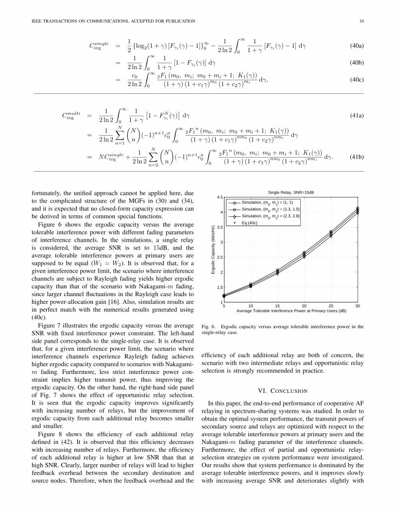
Figure 6 shows the ergodic capacity versus the averagetolerable interference power with different fading parametersof interference channels. In the simulations, a single relayis considered, the average SNR is set to 15dB, and theaverage tolerable interference powers at primary users aresupposed to be equal (𝑊1 = 𝑊2). It is observed that, for agiven interference power limit, the scenario where interferencechannels are subject to Rayleigh fading yields higher ergodiccapacity than that of the scenario with Nakagami-𝑚 fading,since larger channel fluctuations in the Rayleigh case leads tohigher power-allocation gain [16]. Also, simulation results arein perfect match with the numerical results generated using(40c).
Figure 7 illustrates the ergodic capacity versus the averageSNR with fixed interference power constraint. The left-handside panel corresponds to the single-relay case. It is observedthat, for a given interference power limit, the scenario whereinterference channels experience Rayleigh fading achieveshigher ergodic capacity compared to scenarios with Nakagami-𝑚 fading. Furthermore, less strict interference power con-straint implies higher transmit power, thus improving theergodic capacity. On the other hand, the right-hand side panelof Fig. 7 shows the effect of opportunistic relay selection.It is seen that the ergodic capacity improves significantlywith increasing number of relays, but the improvement ofergodic capacity from each additional relay becomes smallerand smaller.
Figure 8 shows the efficiency of each additional relaydefined in (42). It is observed that this efficiency decreaseswith increasing number of relays. Furthermore, the efficiencyof each additional relay is higher at low SNR than that athigh SNR. Clearly, larger number of relays will lead to higherfeedback overhead between the secondary destination andsource nodes. Therefore, when the feedback overhead and the
5 10 15 20 25 301
1.5
2
2.5
3
3.5
4
4.5
Average Tolerable Interference Power at Primary Users (dB)
Erg
odic
Cap
acity
(bi
t/s/H
z)
Single Relay, SNR=15dB
Simulation, (m
0, m
1) = (1, 1)
Simulation, (m0, m
1) = (1.3, 1.5)
Simulation, (m0, m
1) = (2.3, 2.8)
Eq.(40c)
Fig. 6. Ergodic capacity versus average tolerable interference power in thesingle-relay case.
efficiency of each additional relay are both of concern, thescenario with two intermediate relays and opportunistic relayselection is strongly recommended in practice.
VI. CONCLUSION
In this paper, the end-to-end performance of cooperative AFrelaying in spectrum-sharing systems was studied. In order toobtain the optimal system performance, the transmit powers ofsecondary source and relays are optimized with respect to theaverage tolerable interference powers at primary users and theNakagami-𝑚 fading parameter of the interference channels.Furthermore, the effect of partial and opportunistic relay-selection strategies on system performance were investigated.Our results show that system performance is dominated by theaverage tolerable interference powers, and it improves slowlywith increasing average SNR and deteriorates slightly with

IEEE TRANSACTIONS ON COMMUNICATIONS, ACCEPTED FOR PUBLICATION 11
0 10 20 302
2.5
3
3.5
4
4.5
5
Average SNR (dB)
Erg
odic
Cap
acity
[bit/
s/H
z]Single Relay
m0=m
1=1
m0=1.3, m
1=1.5
m0=2.3, m
1=2.8
Eq.(40c)
0 10 20 302
2.5
3
3.5
4
4.5
5
Average SNR (dB)
Erg
odic
Cap
acity
[bit/
s/H
z]
Relay Selection, m0=m
1=1, W
1=W
2=20dB
SimulationEq.(41b)
W1=W
2=30dB
W1=W
2=20dB # relays = 1, 2, 3, 4
Fig. 7. Ergodic capacity versus average SNR for different average tolerableinterference powers.
2 3 4 5 6 7 80.04
0.06
0.08
0.1
0.12
0.14
0.16
0.18
0.2
0.22
Number of Relays
Effe
cien
cy o
f Eac
h A
dditi
onal
Rel
ay
m0=m
1=1, W
1=W
2=20dB
SNR=10dBSNR=20dBSNR=30dB
Fig. 8. Efficiency of each additional relay.
larger values of the Nakagami-𝑚 fading parameters pertain-ing to the interference channels. When the average tolerableinterference powers are low, the scheme with opportunisticrelay selection among two intermediate relays is recommendedto improve system performance significantly without heavilyincreasing the feedback overhead.
ACKNOWLEDGEMENT
This study was supported in part by King Abdullah Uni-versity of Science and Technology (KAUST), Thuwal, SaudiArabia.
REFERENCES
[1] J. M. Peha, “Approaches to spectrum sharing,” IEEE Commun. Mag.,vol. 43, no. 2, pp. 10-12, Feb. 2005.
[2] L. Musavian and S. Aı̈ssa, “Fundamental capacity limits of cognitiveradio in fading environments with imperfect channel information,” IEEETrans. Commun., vol. 57, no. 11, pp. 3472-3480, Nov. 2009.
[3] M. Xia, C. Xing, Y.-C. Wu, and S. Aı̈ssa, “Exact performance analysisof dual-hop semi-blind AF relaying over arbitrary Nakagami-𝑚 fadingchannels,” IEEE Trans. Wireless. Commun., vol. 10, no. 10, pp. 3449-3459, Oct. 2011.
[4] L. Musavian and S. Aı̈ssa, “Cross-layer analysis of cognitive radio relaynetworks under quality of service constraints,” in Proc. IEEE Veh. Tech.Conf. (VTC-S’09), Barcelona, Spain, pp. 1-5, Apr. 2009.
[5] L. Musavian, S. Aı̈ssa, and S. Lambotharan, “Effective capacity forinterference and delay constrainted cognitive radio relay channels,” IEEETrans. Wireless Commun., vol. 9, no. 5, pp. 1698-1707, May 2010.
[6] K. B. Fredj, L. Musavian, and S. Aı̈ssa, “Closed-form expressions forthe capacity of spectrum-sharing constrained relaying systems,” in Proc.17th IEEE Int. Conf. Telecomm. (ICT’10), Doha, Qatar, pp. 476-480.Apr. 2010.
[7] J. Lee, H. Wang, J. G. Andrews, and D. Hong, “Outage probabilityof cognitive relay networks with interference constraints,” IEEE Trans.Wireless Commun., vol. 10, no. 2, pp. 390-395, Feb. 2011.
[8] V. Asghari and S. Aı̈ssa, “Cooperative relay communication performanceunder spectrum-sharing resource requirements,” in Proc. IEEE Int. Conf.Commun. (ICC’10), Cape Town, South Africa, pp. 1-6, May 2010.
[9] V. Asghari and S. Aı̈ssa, “End-to-end performance of cooperative relayin spectrum-sharing systems with quality of service requirements,” IEEETrans. Veh. Technol., vol. 60, no. 6, pp. 2656-2668, June 2011.
[10] M. O. Hasna and M.-S. Alouini, “End-to-end performance of transmis-sion systems with relays over Rayleigh-fading channels,” IEEE Trans.Wireless Commun., vol. 2, no. 6, pp. 1126-1131, Nov. 2003.
[11] A. J. Goldsmith and P. P. Varajya, “Capacity of fading channels withchannel side information,” IEEE Trans. Inf. Theory, vol. 43, no. 6,pp. 1986-1992, Nov. 1997.
[12] A. Bletsas, A. Khisti, D. P. Reed, and A. Lippman, “A simple cooperativediversity method based on network path selection,” IEEE J. Select. AreaCommun., vol. 24, no. 3, pp. 659-672, Mar. 2006.
[13] A. Adinoyi, Y. Fan, H. Yanikomeroglu, H. V. Poor, and F. Al-Shaalan,“Performance of selection relaying and cooperative diversity,” IEEETrans. Wireless Commun., vol. 8, no. 12, pp. 5790-5795, Dec. 2009.
[14] I. S. Gradshteyn and I. M. Ryzhik, Table of Integrals, Series andProducts, 7th Ed., Academic Press, 2007.
[15] A. P. Prudnikov, Y. A. Brychkov, and O. I. Marichev, Integrals andSeries, Gordon and Breach Science Publishers, 1986.
[16] J.-P. Hong and W. Choi, “Throughput characteristics by multiuserdiversity in a cognitive radio system,” IEEE Trans. Signal Proces.,vol. 59, no. 8, pp. 3749-3763, Aug. 2011.
[17] J. G. Proakis, Digital Communications, 4th Ed., McGraw-Hill Com.,Inc., 2001.
[18] M. K. Simon and M.-S. Alouini, Digital Communication over FadingChannels, 2nd Ed., John Wiley & Sons Inc., 2005.
[19] M. R. McKay, A. Zanella, I. B. Collings, and M. Chiani, “Errorprobability and SINR analysis of optimum combining in Rician fading,”IEEE Trans. Commun., vol. 57, no. 3, pp. 676-687, Mar. 2009.
[20] V. Asghari, A. Maaref, and S. Aı̈ssa, “Symbol error probability analysisfor multihop relay over Nakagami fading channels,” in Proc. IEEE Wire-less Commun. and Networking Conf. (WCNC’10), Sydney, Australia,pp. 1-5, Apr. 2010.
[21] Z. Wang and G. B. Giannakis, “A simple and general parameterizationquantifying performance in fading channels,” IEEE Trans. Commun.,vol. 51, no. 8, pp. 1389-1398, Aug. 2003.
[22] L. Zheng and D. N. C. Tse, “Diversity and multiplexing: A fundamentaltradeoff in multiple-antenna channels,” IEEE Trans. Inf. Theory, vol. 49,no. 5, pp. 1073-1096, May 2003.
[23] R. U. Nabar, H. Bolcskei, and A. J. Paulraj, “Diversity and outageperformance in space-time block coded Ricean MIMO channels,” IEEETrans. Wireless Commun., vol. 4, no. 5, pp. 2519-2532, Sep. 2005.
[24] H. Lee, J. G. Andrews, and E. J. Powers, “Information outage probabilityand diversity order of symmetric coordinate interleaved orthogonaldesigns,” IEEE Trans. Wireless Commun., vol. 7, no. 5, pp. 1501-1506,May 2008.
[25] N. Yang, M. Elkashlan, and J. Yuan, “Impact of opportunistic schedulingon cooperative dual-hop relay networks,” IEEE Trans. Commun., vol. 59,no. 3, pp. 689-694, Mar. 2011.
[26] M. D. Renzo, F. Graziosi, and F. Santucci, “Channel capacity over gen-eralized fading channels: A novel MGF-based approach for performanceanalysis and design of wireless communication systems,” IEEE Trans.Veh. Technol., vol. 59, no. 1, pp. 127-149, Jan. 2010.

IEEE TRANSACTIONS ON COMMUNICATIONS, ACCEPTED FOR PUBLICATION 12
Minghua Xia obtained his Ph.D. degree in Telecom-munications and Information Systems from Sun Yat-sen University, Guangzhou, China, in 2007. FromMar. 2007 to July 2009, he was with the Electronicsand Telecommunications Research Institute (ETRI)of South Korea, Beijing R&D Center, Beijing,China, where he worked as a member of engineeringstaff and participated in the projects on the physicallayer design of 3GPP LTE mobile communications.From Aug. 2009 to Feb. 2011, he was with TheUniversity of Hong Kong (HKU), Hong Kong, as
a Postdoctoral Fellow. Currently, he is with King Abdullah University ofScience and Technology (KAUST), Saudi Arabia. His research interests arein the area of network information theory and space-time signal processing,and in particular the design and performance analysis of multi-user multi-antenna systems, cooperative relaying systems, and cognitive radio networks.
Sonia Aı̈ssa (S’93-M’00-SM’03) received her Ph.D.degree in Electrical and Computer Engineeringfrom McGill University, Montreal, QC, Canada, in1998. Since then, she has been with the NationalInstitute of Scientific Research-Energy, Materials,and Telecommunications (INRS-EMT), Universityof Quebec, Montreal, QC, Canada, where she is aProfessor.
From 1996 to 1997, she was a Researcher withthe Department of Electronics and Communicationsof Kyoto University, Kyoto, Japan, and with the
Wireless Systems Laboratories of NTT, Kanagawa, Japan. From 1998 to 2000,she was a Research Associate at INRS-EMT, Montreal. From 2000 to 2002,while she was an Assistant Professor, she was a Principal Investigator inthe major program of personal and mobile communications of the CanadianInstitute for Telecommunications Research (CITR), leading research in radioresource management for code division multiple access systems. From 2004to 2007, she was an Adjunct Professor with Concordia University, Montreal.In 2006, she was Visiting Invited Professor with the Graduate School ofInformatics, Kyoto University, Kyoto, Japan. Her research interests lie inthe area of wireless and mobile communications, and include radio resourcemanagement, cross-layer design and optimization, design and analysis ofmultiple antenna (MIMO) systems, cognitive and cooperative transmissiontechniques, and performance evaluation, with a focus on Cellular, Ad Hoc,and Cognitive Radio networks.
Dr. Aı̈ssa was the Founding Chair of the Montreal Chapter IEEE Womenin Engineering Society in 2004-2007, acted or is currently acting as TechnicalProgram Leading Chair or Cochair for the Wireless Communications Sym-posium of the IEEE International Conference on Communications (ICC) in2006, 2009, 2011 and 2012, as PHY/MAC Program Chair for the 2007 IEEEWireless Communications and Networking Conference (WCNC), and as Tech-nical Program Committee Cochair of the 2013 IEEE Vehicular TechnologyConference - spring (VTC). She has served as a Guest Editor of the EURASIPJournal on Wireless Communications and Networking in 2006, and as Asso-ciate Editor of the IEEE WIRELESS COMMUNICATIONS MAGAZINE in 2006-2010. She is currently an Editor of the IEEE TRANSACTIONS ON WIRELESSCOMMUNICATIONS, the IEEE TRANSACTIONS ON COMMUNICATIONS andthe IEEE COMMUNICATIONS MAGAZINE, and Associate Editor of the WileySecurity and Communication Networks Journal. Awards and distinctions toher credit include the Quebec Government FQRNT Strategic Fellowship forProfessors-Researchers in 2001-2006; the INRS-EMT Performance Award in2004 and 2011 for outstanding achievements in research, teaching and service;the IEEE Communications Society Certificate of Appreciation in 2006-2011;and the Technical Community Service Award from the FQRNT Center forAdvanced Systems and Technologies in Communications (SYTACom) in2007. She is also co-recipient of Best Paper Awards from IEEE ISCC 2009,WPMC 2010, IEEE WCNC 2010 and IEEE ICCIT 2011; and recipient ofNSERC (Natural Sciences and Engineering Research Council of Canada)Discovery Accelerator Supplement Award.


![Cooperative Spectrum Sharing Based Relaying Protocols ...arXiv:1508.06589v3 [cs.NI] 22 Mar 2018 1 Cooperative Spectrum Sharing Based Relaying Protocols With Wireless Energy Harvesting](https://img.pdfslide.net/doc/110x75/601ad94ce8b7ef570958a2d5/cooperative-spectrum-sharing-based-relaying-protocols-arxiv150806589v3-csni.jpg)