Embed Size (px)
Citation preview

Cooperative Control and Modeling for Narrow PassageTraversal with an Ornithopter MAV and Lightweight Ground
Station
Ryan C. JulianDepartment of EECS
Univ. of California, BerkeleyBerkeley, CA 94720
Cameron J. RoseDepartment of EECS
Univ. of California, BerkeleyBerkeley, CA 94720
Humphrey HuRobotics Institute
Carnegie Mellon UniversityPittsburgh, PA [email protected]
Ronald S. FearingDepartment of EECS
Univ. of California, BerkeleyBerkeley, CA 94720
ABSTRACTThe power, size, and weight constraints of micro air vehicles(MAVs) limit their on-board sensing and computational re-sources. Ground vehicles have less mobility than MAVs,but relaxed size constraints, and typically more computingpower. These specializations present many opportunitiesfor robot-robot cooperation. In this work, we demonstratecooperative target-seeking between a 13 gram ornithopterMAV and a lightweight ground station using computer vi-sion. We develop models for the ornithopter, ground station,and cooperative system dynamics. We determine model pa-rameters of the real systems through experimental systemidentification. Finally, we verify those models using experi-ments on narrow passage traversal, and arrive at a coopera-tive system model which accurately predicts the backwards-reachable region for successfully negotiating ornithopter flightthrough narrow passages.
We also introduce a new ornithopter MAV, the 13 gramH2Bird. It features clap and fling wings, improves uponprevious designs by utilizing a carbon fiber airframe, tail ro-tor, and elevator, and carries a 2.8 gram payload. We aug-ment the ornithopter’s built-in gyroscope-based control witha lightweight ground station, which has power and weightrequirements appropriate for deployment on ground vehi-cles with 10 gram payloads. The ground station providesheading estimates to the ornithopter by running a real-timemotion tracking algorithm over a live video stream.
Categories and Subject DescriptorsI.2.9 [Robotics]: Autonomous Vehicles; I.2.9 [Robotics]:Distributed Artificial Intelligence—Multiagent Systems; I.2.9[Robotics]: Vision and Scene Understanding—Motion
Appears in: Proceedings of the 12th International Confer-ence on Autonomous Agents and Multiagent Systems (AA-MAS 2013), Ito, Jonker, Gini, and Shehory (eds.), May,6–10, 2013, Saint Paul, Minnesota, USA.Copyright c© 2013, International Foundation for Autonomous Agents andMultiagent Systems (www.ifaamas.org). All rights reserved.
Figure 1: H2Bird ornithopter MAV
General TermsAlgorithms, Performance, Design, Experimentation
KeywordsAAMAS proceedings, multiagent systems, cooperative con-trol, particle filter, micro air vehicle, ground station, vi-sual servoing, pose estimation, flapping wing, ornithopter,biomimetic
1. INTRODUCTIONPower, size, and weight constraints on 10 gram scale mi-
cro air vehicles (MAVs) significantly limit their sensing andcomputational capabilities. MAVs can execute only low-complexity control and state estimation algorithms in real-time. The constraints on flapping-wing MAVs are even morerestrictive. Although they demonstrate safety and noise pro-files superior to those of rotorcraft MAVs, this comes at theexpense of reduced payload.
The non-linear dynamics of flapping-wing flight compoundthese constraints [4][12]. Much past research on flapping-wing MAVs focuses on overcoming the difficulties of con-trolling and modeling flapping-wing vehicles in the face ofthis non-linearity [9]. Common approaches to simplify thesedynamic models include averaging over the wing-beat pe-riod [4][25], and using linear, low-dimensional models to pre-dict flight behavior [26]. These advances led to the devel-opment of high-performance platforms such as the sub-15gram DelFly, described by deCroon et al. [5].
Many control laws, such as periodic forcing and other con-trol methods described by [7][15][19], require powerful on-board computing. In this work, we develop a simpler, lesscomputationally-intensive method of control for negotiatingnarrow passages, by exploiting cooperation between special-ized robotic agents.
In contrast to flight control, there is considerably lessprevious work on guidance and navigation of flapping-wingMAVs. Baek demonstrated altitude control with an externalcamera [2]. de Croon et al. demonstrated obstacle avoid-ance with an onboard camera and offboard processing [6].Baek et al. provide one of the few examples of completelyautonomous target seeking for vehicles at the sub-20 gramscale [3].
There also exists a body of work on the guidance and con-trol of fixed- and rotary-wing MAV platforms, but many ofthese methods make extensive use of GPS or motion cap-ture systems [14][16]. Indoors, using GPS to estimate thepose of an MAV is unreliable, and motion capture requiresextensive and stationary modification of the environment.
The literature on cooperative control of MAVs is similarlylimited to larger vehicles or analytical explorations. Hyamset al., Jung et al. and Nebot et al. all demonstrated coop-erative visual servoing for heterogeneous UGVs [11][13][22].Luo, et al. and Mehta, et al. analyze UAV-UGV coop-eration from a modeling perspective [20][21]. Rudol et al.demonstrated a similar cooperative visual servoing systemwith UGVs and MAVs [24], but the vehicles used were ordersof magnitude larger than the lightweight systems we target,and so were able to take advantage of high-performance pro-cessors and specialized cameras. Stirling et al. describe amethod for cooperation amongst quadrotor MAVs to navi-gate an indoor environment [27]. Stationary MAVs provideexternal sensing for navigation through the environment,and the network can be extended by using the exploringMAVs for sensing in undiscovered areas. Their implementa-tion relies solely on local sensing, although our size range re-quires that the actual environment sensing be external to theMAV. Additionally, they do not consider time constraints intheir planning, whereas our MAV has a minimum forwardspeed and turning radius. The small size of lightweight airand ground vehicles necessitates specialization, but it alsopays dividends in agility. A group of specialized hetero-geneous, lightweight robots can navigate more challengingterrains and interact with their environments in ways thatlarger, monolithic vehicles cannot. Despite this advantage,in order to collectively equal the sensing and computationalcapabilities of larger robots, small robots will have to in-teract so that multiple robots can benefit from the special-ized capabilities of cooperating vehicles. In this paper weconsider both experimentally, and in simulation, the perfor-mance of the externally-directed ornithopter to demonstratehow millirobotic system can benefit from cooperation.
Wings
ImageProc
Elevator servo
Tail elevator
Tail prop
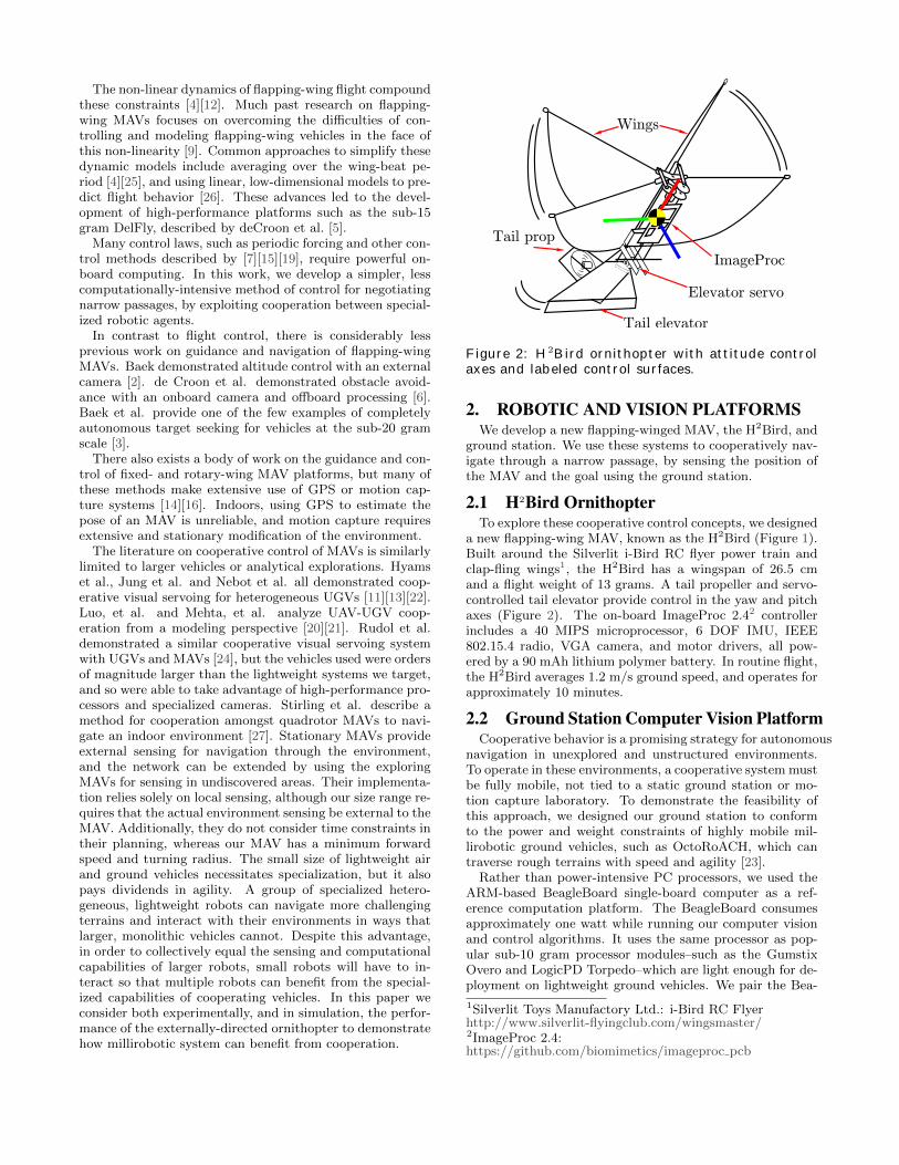
Figure 2: H2Bird ornithopter with attitude controlaxes and labeled control surfaces.
2. ROBOTIC AND VISION PLATFORMSWe develop a new flapping-winged MAV, the H2Bird, and
ground station. We use these systems to cooperatively nav-igate through a narrow passage, by sensing the position ofthe MAV and the goal using the ground station.
2.1 H2Bird OrnithopterTo explore these cooperative control concepts, we designed
a new flapping-wing MAV, known as the H2Bird (Figure 1).Built around the Silverlit i-Bird RC flyer power train andclap-fling wings1, the H2Bird has a wingspan of 26.5 cmand a flight weight of 13 grams. A tail propeller and servo-controlled tail elevator provide control in the yaw and pitchaxes (Figure 2). The on-board ImageProc 2.42 controllerincludes a 40 MIPS microprocessor, 6 DOF IMU, IEEE802.15.4 radio, VGA camera, and motor drivers, all pow-ered by a 90 mAh lithium polymer battery. In routine flight,the H2Bird averages 1.2 m/s ground speed, and operates forapproximately 10 minutes.
2.2 Ground Station Computer Vision PlatformCooperative behavior is a promising strategy for autonomous
navigation in unexplored and unstructured environments.To operate in these environments, a cooperative system mustbe fully mobile, not tied to a static ground station or mo-tion capture laboratory. To demonstrate the feasibility ofthis approach, we designed our ground station to conformto the power and weight constraints of highly mobile mil-lirobotic ground vehicles, such as OctoRoACH, which cantraverse rough terrains with speed and agility [23].
Rather than power-intensive PC processors, we used theARM-based BeagleBoard single-board computer as a ref-erence computation platform. The BeagleBoard consumesapproximately one watt while running our computer visionand control algorithms. It uses the same processor as pop-ular sub-10 gram processor modules–such as the GumstixOvero and LogicPD Torpedo–which are light enough for de-ployment on lightweight ground vehicles. We pair the Bea-
1Silverlit Toys Manufactory Ltd.: i-Bird RC Flyerhttp://www.silverlit-flyingclub.com/wingsmaster/2ImageProc 2.4:https://github.com/biomimetics/imageproc pcb
Camera Beagle Board Radio MCU Flight
Dynamics
Camera Frame Position Desired
Heading
Heading Error
Actuator Input
Gyro Estimated Heading
Ground Station H2Bird
Pose
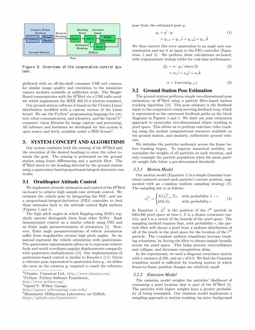
Figure 3: Overview of the cooperative control sys-tem.
gleBoard with an off-the-shelf consumer USB web camera,for similar image quality and resolution to the miniaturecamera modules available at millirobot scale. The Beagle-Board communicates with the H2Bird via a USB radio mod-ule which implements the IEEE 802.15.4 wireless standard.
Our ground station software is based on the Ubuntu Linux3
distribution modified with a custom version of the Linuxkernel. We use the Python4 programming language for con-trol, robot communication, and telemetry, and the OpenCV5
computer vision libraries for image capture and processing.All software and hardware we developed for this system isopen source and freely available under a BSD license6.
3. SYSTEM CONCEPT AND ALGORITHMSOur system combines both the sensing of the H2Bird and
the execution of the desired headings to steer the robot to-wards the goal. The sensing is performed on the groundstation using frame differencing and a particle filter. TheH2Bird steers to the heading directed by the ground stationusing a quaternion-based proportional-integral-derivative con-troller.
3.1 Ornithopter Attitude ControlWe implement attitude estimation and control of the H2Bird
on-board to achieve high sample-rate attitude control. Weestimate the vehicle pose by integrating the IMU, and usea proportional-integral-derivative (PID) controller to feedthese estimates back to the attitude control flight surfaces(Figures 3 and 4).
The high pitch angles at which flapping-wing MAVs reg-ularly operate distinguish them from other MAVs. Baekdemonstrated control on a similar vehicle using PID andan Euler angle parameterization of orientation [3]. How-ever, Euler angle parameterizations of vehicle orientationsuffer from singularities around high pitch angles. So weinstead represent the vehicle orientation with quaternions.The quaternion representation allows us to represent relativebody and world coordinate angular displacements compactlywith quaternion multiplication [10]. Our implementation ofquaternion-based control is similar to Knoebe’s [17]: Givena reference pose represented in quaternion form qr, we definethe error as the rotation qe required to reach the reference
3Ubuntu: Canonical Ltd., http://www.ubuntu.com/4Python: Python Software Foundation,http://www.python.org/5OpenCV: Willow Garage,http://opencv.willowgarage.com/wiki/6Biomimetic Millisystems Laboratory on GitHub,https://github.com/biomimetics
pose from the estimated pose q:
qe = q′ · qr (1)
= qe,w + qe,x i+ qe,y j + qe,z k
We then convert this error quaternion to an angle axis rep-resentation and use it as input to the PID controller (Equa-tions 2 and 3). We perform these calculations on-board,with trigonometric lookup tables for real-time performance.
Qe = α · qe/ sin(α/2) (2)
= αx i+ αy j + αz k
α = 2 arccos(qe,w) (3)
3.2 Ground Station Pose EstimationThe ground station performs simple two-dimensional pose
estimation on H2Bird using a particle filter-based motiontracking algorithm [28]. This pose estimate is the feedbackinput to the cooperative visual servoing feedback loop, whichis represented as the outermost feedback paths on the blockdiagrams in Figures 3 and 4. We limit our pose estimationapproach to monocular two-dimensional object tracking inpixel space. This allows us to perform real-time video track-ing using the modest computational resources available onthe ground station, and similarly, millirobotic ground vehi-cles.
We initialize the particles uniformly across the frame be-fore tracking begins. To improve numerical stability, wenormalize the weights of all particles on each iteration, andonly resample the particle population when the mean parti-cle weight falls below a pre-determined threshold.
3.2.1 Motion ModelOur motion model (Equation 4) is a simple Gaussian tran-
sition centered around each particle’s current position, aug-mented with an ε-random uniform sampling strategy [8].The sampling law is as follows:
x[i]t ∼
{N (x
[i]t−1,Σ), with probability 1− ε
U(0, b), with probability ε(4)
In Equation 4, x[i]t is the position of the ith particle in
640x480 pixel space at time t, Σ is a chosen covariance ma-trix, and b is a vector of the bounds of the pixel space. Thesampling method requires that, with probability ε, the par-ticle filter will choose a pixel from a uniform distribution ofall of the pixels in the pixel space for the location of the ith
particle. The ε-random uniform transitions increase track-ing robustness, by forcing the filter to always sample broadlyacross the pixel space. This helps prevent overconfidenceand collapse, and decreases reacquisition delay.
In the experiments, we used a diagonal covariance matrixwith a variance of 256, and an ε of 0.3. We find the Gaussiantransition model is sufficient for tracking motion in whichframe-to-frame position changes are relatively small.
3.2.2 Emission ModelThe emission model weights the particles’ likelihood of
containing a pixel location that is part of the H2Bird [8].The particles with higher weights have a greater probabil-ity of being resampled. Our emission model implements asampling approach to motion tracking via naıve background
P-D Controller
Pose
Angular position
Desired Heading
PIDController
Camera
Window position
Internal Control Loop – 300Hz
External Control Loop – 10Hz
Pose Estimation
Translational Position
-Attitude
Estimation
OrnithopterDynamics
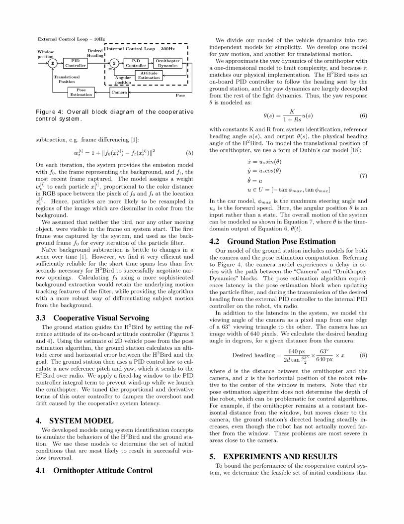
Figure 4: Overall block diagram of the cooperativecontrol system.
subtraction, e.g. frame differencing [1]:
w[i]t = 1 + ‖f0(x
[i]t )− ft(x[i]t )‖2 (5)
On each iteration, the system provides the emission modelwith f0, the frame representing the background, and ft, themost recent frame captured. The model assigns a weight
w[i]t to each particle x
[i]t , proportional to the color distance
in RGB space between the pixels of f0 and ft at the location
x[i]t . Hence, particles are more likely to be resampled in
regions of the image which are dissimilar in color from thebackground.
We assumed that neither the bird, nor any other movingobject, were visible in the frame on system start. The firstframe was captured by the system, and used as the back-ground frame f0 for every iteration of the particle filter.
Naıve background subtraction is brittle to changes in ascene over time [1]. However, we find it very efficient andsufficiently reliable for the short time spans–less than fiveseconds–necessary for H2Bird to successfully negotiate nar-row openings. Calculating f0 using a more sophisticatedbackground extraction would retain the underlying motiontracking features of the filter, while providing the algorithmwith a more robust way of differentiating subject motionfrom the background.
3.3 Cooperative Visual ServoingThe ground station guides the H2Bird by setting the ref-
erence attitude of its on-board attitude controller (Figures 3and 4). Using the estimate of 2D vehicle pose from the poseestimation algorithm, the ground station calculates an alti-tude error and horizontal error between the H2Bird and thegoal. The ground station then uses a PID control law to cal-culate a new reference pitch and yaw, which it sends to theH2Bird over radio. We apply a fixed-lag window to the PIDcontroller integral term to prevent wind-up while we launchthe ornithopter. We tuned the proportional and derivativeterms of this outer controller to dampen the overshoot anddrift caused by the cooperative system latency.
4. SYSTEM MODELWe developed models using system identification concepts
to simulate the behaviors of the H2Bird and the ground sta-tion. We use these models to determine the set of initialconditions that are most likely to result in successful win-dow traversal.
4.1 Ornithopter Attitude Control
We divide our model of the vehicle dynamics into twoindependent models for simplicity. We develop one modelfor yaw motion, and another for translational motion.
We approximate the yaw dynamics of the ornithopter witha one-dimensional model to limit complexity, and because itmatches our physical implementation. The H2Bird uses anon-board PID controller to follow the heading sent by theground station, and the yaw dynamics are largely decoupledfrom the rest of the fight dynamics. Thus, the yaw responseθ is modeled as:
θ(s) =K
1 +Rsu(s) (6)
with constants K and R from system identification, referenceheading angle u(s), and output θ(s), the physical headingangle of the H2Bird. To model the translational position ofthe ornithopter, we use a form of Dubin’s car model [18]:
x = ussin(θ)
y = uscos(θ)
θ = u
u ∈ U = [− tanφmax, tanφmax]
(7)
In the car model, φmax is the maximum steering angle andus is the forward speed. Here, the angular position θ is aninput rather than a state. The overall motion of the systemcan be modeled as shown in Equation 7, where θ is the time-domain output of Equation 6, θ(t).
4.2 Ground Station Pose EstimationOur model of the ground station includes models for both
the camera and the pose estimation computation. Referringto Figure 4, the camera model experiences a delay in se-ries with the path between the “Camera” and “OrnithopterDynamics” blocks. The pose estimation algorithm experi-ences latency in the pose estimation block when updatingthe particle filter, and during the transmission of the desiredheading from the external PID controller to the internal PIDcontroller on the robot, via radio.
In addition to the latencies in the system, we model theviewing angle of the camera as a pixel map from one edgeof a 63◦ viewing triangle to the other. The camera has animage width of 640 pixels. We calculate the desired headingangle in degrees, for a given distance from the camera:
Desired heading =640 px
2d tan 63◦2
× 63◦
640 px× x (8)
where d is the distance between the ornithopter and thecamera, and x is the horizontal position of the robot rela-tive to the center of the window in meters. Note that thepose estimation algorithm does not determine the depth ofthe robot, which can be problematic for control algorithms.For example, if the ornithopter remains at a constant hor-izontal distance from the window, but moves closer to thecamera, the ground station’s directed heading steadily in-creases, even though the robot has not actually moved far-ther from the window. These problems are most severe inareas close to the camera.
5. EXPERIMENTS AND RESULTSTo bound the performance of the cooperative control sys-
tem, we determine the feasible set of initial conditions that
−3 −2 −1 0 1 2 3−0.2
0
0.2
0.4
0.6
0.8
1
1.2
1.4
1.6
Time [sec]
Yaw
Rota
tion [
rad]
Reference YawMeasured YawFitted Model
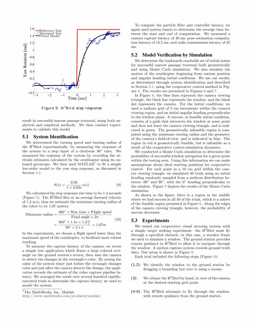
Figure 5: H2Bird step response
result in successful narrow passage traversal, using both an-alytical and empirical methods. We then conduct experi-ments to validate this model.
5.1 System IdentificationWe determined the turning speed and turning radius of
the H2Bird experimentally, by measuring the response ofthe system to a step input of a clockwise 90◦ turn. Wemeasured the response of the system by recording the at-titude estimates calculated by the ornithopter using its on-board gyroscope. We then used MATLAB7 to fit a simplelow-order model to the yaw step response, as discussed inSection 4.1:
θ(s) =0.95
1 + 0.62su(s) (9)
We calculated the step response rise time to be 1.4 seconds(Figure 5). The H2Bird flies at an average forward velocityof 1.2 m/s, thus we estimate the minimum turning radius ofthe robot to be 1.07 meters:
Minimum radius =360◦ × Rise time× Flight speed
Final angle× 2π
=360◦ × 1.4s× 1.2m
s
90◦ × 2 ∗ π = 1.07m
(10)
In the experiments, we choose a flight speed lower than themaximum speed of the ornithopter, to facilitate more robusttracking.
To measure the capture latency of the camera, we wrotea simple test application which draws a large colored rect-angle on the ground station’s screen, then uses the camerato detect the changes in the rectangle’s color. By noting thevalue of the system timer just before the rectangle changescolor and just after the camera detects the change, the appli-cation records the estimate of the video capture pipeline la-tency. We averaged the result over several hundred rapidly-executed trials to determine the capture latency we used tomodel the system.
7The MathWorks, Inc. Matlab:http://www.mathworks.com/products/matlab/
To compute the particle filter and controller latency, weagain used system timers to determine the average time be-tween the start and end of computation. We measured acamera capture latency of 40 ms, pose estimation computa-tion latency of 12.5 ms, and radio transmission latency of 25ms.
5.2 Model Verification by SimulationWe determine the backwards reachable set of initial states
for successful narrow passage traversal both geometricallyand using Monte Carlo simulation. We also simulate themotion of the ornithopter beginning from various positionand angular heading initial conditions. We use our model,as determined through system identification and describedin Section 5.1, using the cooperative control method in Fig-ure 4. The results are presented in Figures 6 and 7.
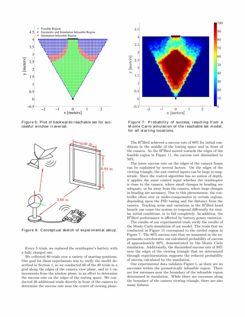
In Figure 6, the blue lines represent the camera viewingtriangle, the black line represents the window, and the blackdot represents the camera. For the initial conditions, weused a uniform grid of 5 cm increments within the cameraviewing region, and an initial angular heading perpendicularto the window plane. A success, or feasible initial condition,consists of a path that intersects the window at some pointand does not leave the camera viewing triangle, and is indi-cated in green. The geometrically infeasible region is com-puted using the minimum turning radius and the geometryof the camera’s field-of-view, and is indicated in blue. Theregion in red is geometrically feasible, but is infeasible as aresult of the cooperative control simulation dynamics.
We conducted a Monte Carlo simulation to determine theprobability of successful window navigation for a given pointwithin the testing area. Using this information we can makeassumptions about ideal starting positions for cooperativecontrol. For each point in a 10 cm grid within the cam-era viewing triangle, we simulated 40 trials using an initialheading randomly sampled from a uniform distribution be-tween -90◦ and 90◦, with the 0◦ heading perpendicular tothe window. Figure 7 depicts the results of the Monte Carlosimulation.
As shown in the figure, there is a region in the middlewhere we had success in all 40 of the trials, which is a subsetof the feasible region presented in Figure 6. Along the edgesof the camera viewing triangle, however, the probability ofsuccess decreases.
5.3 ExperimentsWe tested our cooperative visual servoing system with
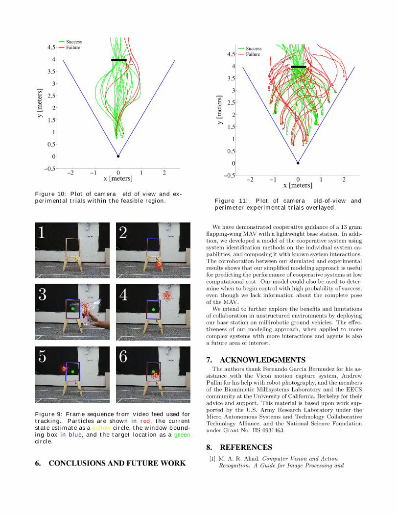
a simple target seeking experiment: the H2Bird must flythrough a specified obstacle, in this case, a wooden framewe used to simulate a window. The ground station providesremote guidance to H2Bird to allow it to navigate throughthe window. A motion capture system records ground truthdata. Our setup is shown in Figure 8.
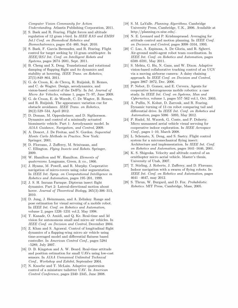
Each trial included the following steps (Figure 9):
(1,2): We identify the window to the ground station bydragging a bounding box over it using a mouse.
(3): We release the H2Bird by hand, in view of the cameraat the desired starting grid point.
(4-6): The H2Bird attempts to fly through the window,with remote guidance from the ground station.
−2 −1 0 1 2−0.5
0
0.5
1
1.5
2
2.5
3
3.5
4
4.5
x [meters]
y [
met
ers]
Feasible Region
Geometric and Simulation Infeasible Region
Simulation Infeasible Region
Figure 6: Plot of backwards reachable set for suc-cessful window traversal.
Figure 7: Probability of success, resulting from aMonte Carlo simulation of the reachable set model,for all starting locations.
0.66 m
0.94 m
3.66 m
Figure 8: Conceptual sketch of experimental setup.
Every 5 trials, we replaced the ornithopter’s battery witha fully charged one.
We collected 80 trials over a variety of starting positions.Our goal for these experiments was to verify the model de-scribed in Section 4, so we conducted 60 of the 80 trials in agrid along the edges of the camera view plane, and in 5 cmincrements from the window plane, in an effort to determinethe success rate on the edges of the testing space. We con-ducted 20 additional trials directly in front of the camera todetermine the success rate near the center of viewing plane.
The H2Bird achieved a success rate of 80% for initial con-ditions in the middle of the testing space and in front ofthe camera. As the H2Bird moved towards the edges of thefeasible region in Figure 11, the success rate diminished to50%.
The lower success rate on the edges of the camera framecan be explained by several factors. On the edges of theviewing triangle, the yaw control inputs can be large in mag-nitude. Since the control algorithm has no notion of depth,it applies the same control input whether the ornithopteris close to the camera, where small changes in heading areadequate, or far away from the camera, where large changesin heading are necessary. Due to this phenomenon, the con-troller often over or under-compensates in certain regions,depending upon the PID tuning and the distance from thecamera. Tracking noise and variations in the H2Bird handlaunch can cause the system to respond differently for simi-lar initial conditions, or to fail completely. In addition, theH2Bird performance is affected by battery power variation.
The results of our experimental trials verify the results ofthe Monte Carlo simulation of our model. The trials that weconducted in Figure 10 correspond to the circled region inFigure 7. The 80% success rate that we measured in the ex-periments corroborates our calculated probability of successof approximately 80%, demonstrated by the Monte Carlosimulation. Additionally, the diminished success rate of 50%near the edges of the viewing triangle that we determinedthrough experimentation supports the reduced probabilityof success calculated by the simulation.
Our experimental data validates Figure 6, as there are nosuccesses within the geometrically infeasible region. Thereare few successes near the boundary of the infeasible regiondetermined in simulation. While there are successes alongthe boundary of the camera viewing triangle, there are alsomany failures.
−2 −1 0 1 2−0.5
0
0.5
1
1.5
2
2.5
3
3.5
4
4.5
x [meters]
y [
met
ers]
Success
Failure
Figure 10: Plot of camera field of view and ex-perimental trials within the feasible region.
−2 −1 0 1 2−0.5
0
0.5
1
1.5
2
2.5
3
3.5
4
4.5
x [meters]
y [
met
ers]
Success
Failure
Figure 11: Plot of camera field-of-view andperimeter experimental trials overlayed.
1 2
3 4
5 6
Figure 9: Frame sequence from video feed used fortracking. Particles are shown in red, the currentstate estimate as a yellow circle, the window bound-ing box in blue, and the target location as a greencircle.
6. CONCLUSIONS AND FUTURE WORK
We have demonstrated cooperative guidance of a 13 gramflapping-wing MAV with a lightweight base station. In addi-tion, we developed a model of the cooperative system usingsystem identification methods on the individual system ca-pabilities, and composing it with known system interactions.The corroboration between our simulated and experimentalresults shows that our simplified modeling approach is usefulfor predicting the performance of cooperative systems at lowcomputational cost. Our model could also be used to deter-mine when to begin control with high probability of success,even though we lack information about the complete poseof the MAV.
We intend to further explore the benefits and limitationsof collaboration in unstructured environments by deployingour base station on millirobotic ground vehicles. The effec-tiveness of our modeling approach, when applied to morecomplex systems with more interactions and agents is alsoa future area of interest.
7. ACKNOWLEDGMENTSThe authors thank Fernando Garcia Bermudez for his as-
sistance with the Vicon motion capture system, AndrewPullin for his help with robot photography, and the membersof the Biomimetic Millisystems Laboratory and the EECScommunity at the University of California, Berkeley for theiradvice and support. This material is based upon work sup-ported by the U.S. Army Research Laboratory under theMicro Autonomous Systems and Technology CollaborativeTechnology Alliance, and the National Science Foundationunder Grant No. IIS-0931463.
8. REFERENCES[1] M. A. R. Ahad. Computer Vision and Action
Recognition: A Guide for Image Processing and
Computer Vision Community for ActionUnderstanding. Atlantis Publishing Corporation, 2011.
[2] S. Baek and R. Fearing. Flight forces and altituderegulation of 12 gram i-bird. In IEEE RAS and EMBSInt.l Conf. on Biomedical Robotics andBiomechatronics, pages 454–460, Sept. 2010.
[3] S. Baek, F. Garcia Bermudez, and R. Fearing. Flightcontrol for target seeking by 13 gram ornithopter. InIEEE/RSJ Int. Conf. on Intelligent Robots andSystems, pages 2674–2681, Sept. 2011.
[4] B. Cheng and X. Deng. Translational and rotationaldamping of flapping flight and its dynamics andstability at hovering. IEEE Trans. on Robotics,27(5):849–864, 2011.
[5] G. de Croon, K. de Clercq, R. Ruijsink, B. Remes,and C. de Wagter. Design, aerodynamics, andvision-based control of the DelFly. In Int. Journal ofMicro Air Vehicles, volume 1, pages 71–97, June 2009.
[6] G. de Croon, E. de Weerdt, C. De Wagter, B. Remes,and R. Ruijsink. The appearance variation cue forobstacle avoidance. IEEE Trans. on Robotics,28(2):529–534, April 2012.
[7] D. Doman, M. Oppenheimer, and D. Sigthorsson.Dynamics and control of a minimally actuatedbiomimetic vehicle. Part 1: Aerodynamic model. InAIAA Guidance, Navigation, and Control, 2009.
[8] A. Doucet, J. De Freitas, and N. Gordon. SequentialMonte Carlo Methods in Practice. New York:Springer, 2001.
[9] D. Floreano, J. Zufferey, M. Srinivasan, andC. Ellington. Flying Insects and Robots. Springer,2009.
[10] W. Hamilton and W. Hamilton. Elements ofquaternions. Longmans, Green, & co., 1866.
[11] J. Hyams, M. Powell, and R. Murphy. Cooperativenavigation of micro-rovers using color segmentation.In IEEE Int. Symp. on Computational Intelligence inRobotics and Automation, pages 195–201, 1999.
[12] J. S. H. Imraan Faruque. Dipteran insect flightdynamics. Part 2: Lateral-directional motion abouthover. Journal of Theoretical Biology, 265(3):306–313,2010.
[13] D. Jung, J. Heinzmann, and A. Zelinksy. Range andpose estimation for visual servoing of a mobile robot.In IEEE Int. Conf. on Robotics and Automation,volume 2, pages 1226–1231 vol.2, May 1998.
[14] T. Kanade, O. Amidi, and Q. Ke. Real-time and 3dvision for autonomous small and micro air vehicles. InIEEE Conf. on Decision and Control, December 2004.
[15] Z. Khan and S. Agrawal. Control of longitudinal flightdynamics of a flapping-wing micro air vehicle usingtime-averaged model and differential flatness basedcontroller. In American Control Conf., pages 5284–5289, July 2007.
[16] D. B. Kingston and A. W. Beard. Real-time attitudeand position estimation for small UAVs using low-costsensors. In AIAA Unmanned Unlimited TechnicalConf., Workshop and Exhibit, September 2004.
[17] N. Knoebe and T. McLain. Adaptive quaternioncontrol of a miniature tailsitter UAV. In AmericanControl Conference, pages 2340–2345, June 2008.
[18] S. M. LaValle. Planning Algorithms. CambridgeUniversity Press, Cambridge, U.K., 2006. Available athttp://planning.cs.uiuc.edu/.
[19] N. E. Leonard and P. Krishnaprasad. Averaging forattitude control and motion planning. In IEEE Conf.on Decision and Control, pages 3098–3104, 1993.
[20] C. Luo, A. Espinosa, A. De Gloria, and R. Sgherri.Air-ground multi-agent robot team coordination. InIEEE Int. Conf. on Robotics and Automation, pages6588–6591, May 2011.
[21] S. Mehta, G. Hu, N. Gans, and W. Dixon. Adaptivevision-based collaborative tracking control of an UGVvia a moving airborne camera: A daisy chainingapproach. In IEEE Conf. on Decision and Control,pages 3867–3872, Dec. 2006.
[22] P. Nebot, D. Gomez, and E. Cervera. Agents forcooperative heterogeneous mobile robotics: a casestudy. In IEEE Int. Conf. on Systems, Man andCybernetics, volume 1, pages 557–562 vol.1, Oct. 2003.
[23] A. Pullin, N. Kohut, D. Zarrouk, and R. Fearing.Dynamic turning of 13 cm robot comparing tail anddifferential drive. In IEEE Int. Conf. on Robotics andAutomation, pages 5086 –5093, May 2012.
[24] P. Rudol, M. Wzorek, G. Conte, and P. Doherty.Micro unmanned aerial vehicle visual servoing forcooperative indoor exploration. In IEEE AerospaceConf., pages 1–10, March 2008.
[25] L. Schenato, X. Deng, and S. Sastry. Flight controlsystem for a micromechanical flying insect:Architecture and implementation. In IEEE Int. Conf.on Robotics and Automation, pages 1641–1646, 2001.
[26] K. S. Shigeoka. Velocity and altitude control of anornithopter micro aerial vehicle. Master’s thesis,University of Utah, 2007.
[27] T. Stirling, J. Roberts, J. Zufferey, and D. Floreano.Indoor navigation with a swarm of flying robots. InIEEE Int. Conf. on Robotics and Automation, pages4641 –4647, may 2012.
[28] S. Thrun, W. Burgard, and D. Fox. ProbabilisticRobotics. MIT Press, Cambridge, Mass, 2005.