Embed Size (px)
Citation preview

Coordination of Mobile Devices Technology and Standards Scan
wwwitsdotgovindexhtm Final Report mdash June 19 2015 FHWA-JPO-15-224
Federal Highway Administration
Produced by Battelle Memorial Institute under DTFH61-12-D-00046 US Department of Transportation
FHWA Office of Operations Research and Development
Picture Source US DOT Office of the Assistance Secretary for Research and Technology Intelligent Transportation Systems Joint Program Office
Notice
This document is disseminated under the sponsorship of the Department of Transportation in the interest of information exchange The United States Government assumes no liability for its contents or use thereof
The US Government is not endorsing any manufacturers products or services cited herein and any trade name that may appear in the work has been included only because it is essential to the contents of the work
Technical Report Documentation Page
1 Report No
FHWA-JPO-15-224
2 Government Accession No 3 Recipientrsquos Catalog No
4 Title and Subtitle
Task 2 Conduct Scan of Technology Application Standards and Stakeholder Engagement Technical Memorandum ndash Final Report
5 Report Date
June 19 2015
6 Performing Organization Code
7 Author(s)
Thomas Timcho Eric Plapper Rachel Klein Dr Christopher Toth Brandy Kellom and Ken Vaughn
8 Performing Organization Report No
100053418-201a
9 Performing Organization Name And Address
Battelle 505 King Avenue Columbus OH 43201
10 Work Unit No (TRAIS)
11 Contract or Grant No
DTFH61-12-D-00046
12 Sponsoring Agency Name and Address
US Department of Transportation FHWA Office of Operations Research and Development Turner-Fairbank Highway Research Center 6300 Georgetown Pike McLean VA 22101
13 Type of Report and Period Covered
14 Sponsoring Agency Code
15 Supplementary Notes
Gov Task Monitor ndash Jon Obenberger
16 Abstract
This document presents the technology scan and standards assessment performed for the US DOT project Coordination of Mobile Devices for Connected Vehicle Applications This project seeks to develop personal safety and personal mobility messages that complement the existing basic safety and vehicle situation data messages exchanged in the connected vehicle environment by utilizing mobile devices as a message-capable medium enabling individual users to participate as a connected ldquopersonrdquo
This document presents the terminology and scenario development process used to identify and describe the use case scenarios that will be utilized in the concept and design phases of the project example scenarios are provided to illustrate the range of characteristics each scenario is intended to demonstrate An overview of relevant communication and connected vehicle technology is then presented to identify which technologies are most capable of supporting these use cases Finally a summary of domestic and international industry standards are used to identify which standards are most applicable to incorporating mobile devices into the connected vehicle environment
17 Key Words
Mobile Device Message Coordination Prototype Connected Vehicle Mobile Device Coordinated Mobile Device Personal Mobility Message Personal Safety Message Connected Person Fleet
18 Distribution Statement
19 Security Classif (of this report) 20 Security Classif (of this page) 21 No of Pages
77
22 Price
Form DOT F 17007 (8-72) Reproduction of completed page authorized
Table of Contents
Table of Contents
Table of Contents i Executive Summary iii Chapter 1 Introduction 1 Chapter 2 Stakeholder Engagement 3
TRAVEL STATE 8 TRAVELER MOBILITY CHARACTERISTICS8 TRAVELER SAFETY CHARACTERISTICS9 TRANSPORTATION SYSTEM CHARACTERISTICS10 MESSAGE CHARACTERISTICS 11
Chapter 3 Technology Scan 13
MOBILE DEVICE COMMUNICATION AND SENSOR TECHNOLOGIES 13 Mobile Device Communications Technologies 14 Mobile Device Sensor Technologies 20
MOBILE DEVICE OPERATING SYSTEMS 25 MOBILE DEVICE APPLICATIONS 29 EXISTING AND EMERGING ARCHITECTURE AND MESSAGE FRAMEWORKS 36
Existing Architectures and Practices 36
RELEVANT CONNECTED VEHICLE PROGRAM RESEARCH 39 Mobility Applications 40 Vehicle to Infrastructure (V2I) Safety Applications 45
OTHER TECHNOLOGIES CONSIDERED46 SUMMARY OF TECHNOLOGY SCAN47
Chapter 4 Standards Assessment 48
STANDARDS OVERVIEW 48 ITS MESSAGE SETS 49
SAE J2735 ndash Dedicated Short Range Communications (DSRC) Message Set Dictionary 52
Basic Safety Message 53 Probe Vehicle Data Message 56 Vehicle Situation Data Message 56
SAE J2354 ndash Message Sets for Advanced Traveler Information System (ATIS) 57 APTA-TCIP-S-01 ndash Transit Communications Interface Profiles (TCIP) 58 ISO 19091 ndash Intelligent Transport Systems ndash Cooperative ITS ndash Using V2I and I2V Communications for Applications Related to Signalized Intersections 58
CONNECTED VEHICLE COMMUNICATIONS59 MOBILE NETWORK DATA COMMUNICATIONS 60 BLUETOOTH COMMUNICATIONS61 WI-FI COMMUNICATIONS 61
US Department of Transportation Office of the Assistant Secretary for Research and Technology Intelligent Transportation Systems Joint Program Office
Task 2 Technology and Standards Scan ndash Technical Memorandum | i
Table of Contents
ELECTRONIC PAYMENT 62 IN-VEHICLE COMMUNICATIONS 63 SUMMARY OF STANDARDS ASSESSMENT 63
APPENDIX A Definitions A-1 APPENDIX B Acronyms B-1
List of Tables Table 3-1 Mobile Device Communication Technology Overview 15 Table 3-2 Characteristics of Communication Technologies ndash Means of
Transmission 19 Table 3-3 Hardware and Software Mobile Sensor Descriptions 20 Table 3-4 Characteristics of Communication Technologies ndash Sensor Types 23 Table 3-5 Sensor Hardware in Mobile Devices of Interest to this Project 24 Table 3-6 Sample of Software Characteristics and Applications for Latest iOS and
Android Systems 26 Table 3-7 Mobility Application Descriptions 30 Table 3-8 National ITS Architecture ndash ITS User Services 37 Table 4-1 Domestic Standards Overview 50 Table 4-2 International Standards Overview 51 Table 4-3 International Standards Overview 59 Table 4-4 Comparison of Major US Mobile Network Carrier
StandardsTechnologies 60 Table 4-5 Wi-Fi Device Standards for Select Mobile Devices 61 Table 4-6 Payment Standards Overview 62
List of Figures Figure 2-1 Travel Framework Identifying Coordination Opportunities by Travel
State 5 Figure 2-2 Example of Using the Travel Framework to Express a Two-Person
Transit Trip 6 Figure 2-3 Summary of Characteristics Related to Travel Choices That Can Be
Used to Define Scenarios Where Coordination of Mobile Devices may be needed 7
Figure 3-1 Historic Data Shows Operating System Popularity Trends 25 Figure 3-2 A Timeline of the iOS and Android System Features 28 Figure 3-3 CVRIA 38 Figure 4-1 Basic Safety Message (Part 1) 54 Figure 4-2 Basic Safety Message (Part 2) 55 Figure 4-3 Probe Vehicle Message 56
US Department of Transportation Office of the Assistant Secretary for Research and Technology Intelligent Transportation Systems Joint Program Office
Task 2 Technology and Standards Scan ndash Technical Memorandum | ii
US Department of Transportation Office of the Assistant Secretary for Research and Technology Intelligent Transportation Systems Joint Program Office
Task 2 Technology and Standards Scan ndash Technical Memorandum | iii
Executive Summary
Executive Summary
The connected vehicle environment was envisioned as a means of exchanging messages through a connected vehicle fleet The majority of the current connected vehicle environment focuses on the vehicle by supporting the exchange of messages from vehicle-to-vehicle (V2V) from vehicle-toshyinfrastructure (V2I) and from infrastructure-to-vehicle (I2V) These messages are exchanged to communicate safety and mobility-related messages as a basic safety message (BSM) or a vehicle situation data message (VSM)
This Coordination of Mobile Devices for Connected Vehicle Applications project aims to enhance the connected vehicle environment by incorporating the mobile device in order to facilitate the transmission of personal safety messages (PSM) and personal mobility messages (PMM) that interact with these other systems (ie P2V and P2I exchange of messages) This project seeks to utilize the mobile device as a medium for messages that complement those transmitted by vehicles by adding the connected ldquopersonrdquo fleet dimension to the existing connected vehicle environment
Specific to this report the authors present the preliminary results of the structured technology scan and standards assessment in support of the project This document details the approach used to identify and evaluate the relevant review material characterize current technologies and relevant solutions in the mobile device market and identify and summarize relevant domestic and international vehicular and mobile-device messaging standards Further this project aims to build a foundation for that research by establishing a baseline understanding of how these protocols might coexist what challenges in technology andor standards must be addressed where gaps in current standards and protocols might delay practical incorporation and what issues would a dense concentration of these devices incur
The breadth of potential uses of mobile devices in the connected vehicle environment is vast To provide the context and focus to the research a scenario framework based on real-world use of transportation systems was developed This scenario helped describe various travel states an individual traveler would encounter on a typical trip as well as describing various transitions between coordination points
The team conducted an extensive literature review including relevant US DOT research as well as a scan of industry practices and specifications in the mobile device environment Of particular interest technologies that supported the wireless communication of information as well as the ability of the devices to ascertain data and the current travel state of the user (ie walking on a bus in a bus terminal etc) Finally the team identified and assessed specific relevant work being performed domestically or internationally as it relates to personal safety and mobility messages
The research conducted in this task revealed the following
Specific personal safety and mobility messages do not presently exist in any robust industry-wide formats or specifications neither domestically nor internationally
Numerous common mobile device sensor technologies are embedded in mobile devices that could be used for coordinated communication messaging in the Connected Vehicle environment
Executive Summary
The inclusion of dedicated short-range communications (DSRC) technology in mobile devices is not widespread
There are a number of communication standards that apply to this type of communication some of which can be utilized for coordination among mobile devices and connected vehicles others will require new message sets andor data elements For example
Message format should be consistent with the ASN1 notation and terms presently embodied by the SAE J27352009 Message Set Standard
Message content should utilize to the extent possible the data elements included in the current BSM and the emerging VSM message and others as appropriate but be tailored to meet the needs of the personal safety and mobility messages
Device sensors and communication technologies to include GPS accelerometers gyroscopes proximity sensors NFC Wi-Fi Cellular Bluetooth Bluetooth Low Energy are all ubiquitous across the major mobile device brandssuppliers and can be consistently leveraged to assist with the determination of travel state and corresponding transitions
US Department of Transportation Office of the Assistant Secretary for Research and Technology Intelligent Transportation Systems Joint Program Office
Task 2 Technology and Standards Scan ndash Technical Memorandum | iv
US Department of Transportation Office of the Assistant Secretary for Research and Technology Intelligent Transportation Systems Joint Program Office
Task 2 Technology and Standards Scan ndash Technical Memorandum | 1
Chapter 1 Introduction
Chapter 1 Introduction
The connected vehicle environment was envisioned as a means of exchanging messages through a connected vehicle fleet The majority of the current connected vehicle environment focuses on the vehicle by supporting the exchange of messages from vehicle-to-vehicle (V2V) from vehicle-toshyinfrastructure (V2I) and from infrastructure-to-vehicle (I2V) These messages are exchanged to communicate safety and mobility-related messages as a basic safety message (BSM) or a vehicle situation data message (VSM) This project seeks to develop personal safety and personal mobility messages that complement the existing basic safety and vehicle situation data messages exchanged in the connected vehicle environment by utilizing mobile devices as a message-capable medium enabling individual users to participate as a connected ldquopersonrdquo The mobile device as defined by the US DOT includes smartphones tablets and other hand-held devices that have their own power source and are capable of hosting one or more applications1 Chapter 3 identifies other devices and technologies considered such a lsquowearablersquo biometric sensors carry-in and integrated DSRC devices Smart Watches and the Internet of Things all of which are outside of the scope of this research Likewise messages and the corresponding data elements associated with lsquoenvironmentalrsquo messages while not explicitly excluded are also not within the scope of this research
The US Department of Transportation (US DOT) has conducted significant research on the use of Dedicated Short Range Communications (DSRC) to transmit low-latency information between vehicles and infrastructure Additionally and more recently the communication technologies considered to support in-vehicle and infrastructure systems has expanded to include wireless mobile communication technologies such as 3G and LTE and to a limited degree wireless fidelity (Wi-Fi) and Bluetooth technologies While the research and testing continues in these areas the general interactions and coordination of these systems is generally understood and functions as expected What has not yet been explored in earnest are the benefits and impacts of expanding this connected vehicle network to include interactions with individually-carried personal mobile devices This project aims to build a foundation for that research by establishing a baseline understanding of how these protocols might coexist what challenges in technology andor standards must be addressed where gaps in current standards and protocols might delay practical incorporation and what issues would a dense concentration of these devices incur
The purpose of this document is to present the preliminary results of the structured technology scan and standards assessment in support of the Coordination for Mobile Devices for Connected Vehicle Applications project This document details the approach used to identify and evaluate the relevant review material characterize current technologies and relevant solutions in the mobile device market and identify and summarize relevant domestic and international vehicular and mobile-device messaging standards
1 From US DOT Final Report ldquoAMS Testbed Requirements for DMA and ATDM Programsrdquo produced by Noblis dated April 5 2013
Chapter 1 Introduction
Assessment of the current state of the technologies standards and communication mechanisms was completed through a number of different activities including
Stakeholder Engagement (Chapter 2)
Technology ScanLiterature Review including discussion on lsquootherrsquo technologies considered (Chapter 3)
Review of Relevant Connected Vehicle Program Research (Chapter 3)
Review of Relevant Standards (Chapter 4)
The following sections summarize the research of each of these activities
US Department of Transportation Office of the Assistant Secretary for Research and Technology Intelligent Transportation Systems Joint Program Office
Task 2 Technology and Standards Scan ndash Technical Memorandum | 2
US Department of Transportation Office of the Assistant Secretary for Research and Technology Intelligent Transportation Systems Joint Program Office
Task 2 Technology and Standards Scan ndash Technical Memorandum | 3
Chapter 2 Stakeholder Engagement
Chapter 2 Stakeholder Engagement
One important resource for gathering information on the current state of technology communications protocols and standards is to identify and solicit information from key stakeholders that are engaged in activities related to mobile devices As summarized in a separate report2 the engagement of these stakeholders was intended to be conducted as part of a technology scan to ensure that technologies standards and other relevant materials were not inadvertently excluded from the findings As such the focus of the engagement of these subject matter experts was to obtain feedback on current technologies and standards relevant to the coordinated and uncoordinated use of mobile devices in the connected vehicle environment
One of the early findings that became apparent fairly quickly in the engagement process was a general confusion and lack of clarity as to the nature of ldquocoordinatedrdquo and ldquouncoordinatedrdquo use of mobile devices in the connected vehicle environment and the nature and points in time throughout a typical trip where such coordination between devices would (or could) occur Also there were significant barriers and challenges associated with differences in terminology that could create additional confusion among stakeholders To overcome these challenges and to provide perspective to stakeholders so that feedback for the project team could be obtained it was determined that a framework that placed the type of information needed into a context of a ldquotypical triprdquo or a ldquoworkday travel scenariordquo where a traveler made a multi-modal trip into work from their home Along with this scenario a common glossary of terms was developed to present this and future scenarios in a consistent fashion This framework and glossary of terms was developed by the project team in coordination with the US DOT staff and a limited set of subject matter experts The following summarizes the developed framework that will be used in subsequent research activities to solicit feedback from a larger Stakeholder group
One of the critical aspects to this project is the concept of ldquocoordinationrdquo between devices in a connected vehicle world In the context of this project ldquocoordinationrdquo refers to the ability of the various devices both mobile and ldquocarry-inrdquo to interact and exchange information so that a consistent and consolidated message is presented externally As an example consider the scenario whereby three persons all with mobile devices are car-sharing a vehicle and all three have mobile devices that are broadcasting a ldquopersonal proberdquo message Without coordination this would result in duplication of messages potentially overtaxing the communications system Alternatively under a coordinated perspective these three travelers and the vehicle would synchronize or coordinate the release of information from these different sources into a single message In abstraction the concept of real-time interaction and coordination between devices to streamline the information flow proved to be a challenging concept to understand and convey As a result a travel scenario framework was developed so that the instances where these coordination activities would be conducted by various devices could be highlighted and considered This framework provides a summary of major activitiesactions that occur with a specific travel statemode of travel (rows of Figure 2-1) at three phases of the trip segment the ldquoBeginningrdquo ldquoEn Routerdquo and at the ldquoEndrdquo of the segment (as denoted by the columns of Figure 2-1) Activitiesactions where some type of coordination of mobile devices would or could occur are indicated by a gold-colored box A description of the specific type or nature
2 Stakeholder List Outreach and Engagement Plan December 17 2014 Produced for US DOT by Battelle Memorial Institute
Chapter 2 Stakeholder Engagement
of the coordination that would occur at each instantiation of a gold-box is summarized in the final column In turn the type nature and implementation methodology for the coordination provides a connection to the types of technologies standards and communication protocols that need to be examined to determine if they can act harmoniously or if there are inconsistencies that would prevent such coordination of communication
The travel framework (Figure 2-1) provides a context to understand the potential coordination opportunities for mobile devices and can be used to generate (by combining multiple rows) specific trip scenarios to provide an end-to-end perspective for all of the various potential coordination points in a given trip For example the following scenario can be expressed (see Figure 2-2) by combining rows and elements presented in Figure 2-1
Two persons living together leave their house and walk to a community bus stop at the end of their street
At the bus stop they meet another neighbor who is waiting for the bus
When the bus arrives they all board the bus and ride it to the central bus station
Definitions for the terms used in this diagram can be found later in Chapter 2
US Department of Transportation Office of the Assistant Secretary for Research and Technology Intelligent Transportation Systems Joint Program Office
Task 2 Technology and Standards Scan ndash Technical Memorandum | 4
Chapter 2 Stakeholder Engagement
Source Battelle
Figure 2-1 Travel Framework Identifying Coordination Opportunities by Travel State
US Department of Transportation Office of the Assistant Secretary for Research and Technology Intelligent Transportation Systems Joint Program Office
Task 2 Technology and Standards Scan ndash Technical Memorandum | 5
Chapter 2 Stakeholder Engagement
As illustrated in Figure 2-2 in this simple scenario there would be four opportunities for mobile devices to be coordinated
1 When the two people leave their house they are in a ldquoTravel State Pedestrianrdquo They would immediately ldquoencounterrdquo each other which would serve as the first opportunity for their mobile devices to coordinate In this case the two personrsquos mobile devices could exchange information and determine that since they meet a predefined criteria such as both belonging to family members only one of the two mobile devices need to broadcast a personal safety message (PSM) or a personal mobility message (PMM) These two mobile devices will have ldquocoordinatedrdquo their information and begin to broadcast as a unit rather than as two separate mobile devices The lsquosizersquo of the region protected will be expanded and as long as the pedestrian remain coordinated and within the radius of the protected region they will broadcast as one
2 When the two persons arrive at the bus stop they encounter the other two potential vehicle passengers As they all have a need for the bus service and they are located at a known bus stop their four mobile devices coordinate information between them and begin to broadcast a single message informing the bus that there are four passengers awaiting pickup (or other message) Alternatively if the bus stop is a ldquoconnected stoprdquo with an inherent communications connection the four mobile devices could all broadcast individual messages to the bus stop which then combines these individual messages into a single message to the onshycoming bus or on-coming vehicles
3 After the bus arrives and the four individuals pay the fare and board the bus their mobile devices could coordinate with the other passengersrsquo devices the transit operator and the transit vehicle itself This could occur through each mobile device coordinating among themselves and determining that only one device would communicate to the transit vehicle that would then send BSM and Probe Messages to other vehicles infrastructure components and pedestrians Alternatively each of the mobile devices could communicate individually with the transit vehicle that then assimilates the information into a single message for broadcast to other vehicles infrastructure and pedestrians
4 As the passengers continue to ride the bus they need to coordinate (and cease to coordinate) with passengers and the transit vehicle
US Department of Transportation Office of the Assistant Secretary for Research and Technology Intelligent Transportation Systems Joint Program Office
Task 2 Technology and Standards Scan ndash Technical Memorandum | 6
Source Battelle
Figure 2-2 Example of Using the Travel Framework to Express a Two-Person Transit Trip
US Department of Transportation Office of the Assistant Secretary for Research and Technology Intelligent Transportation Systems Joint Program Office
Task 2 Technology and Standards Scan ndash Technical Memorandum 7
Chapter 2 Stakeholder Engagement
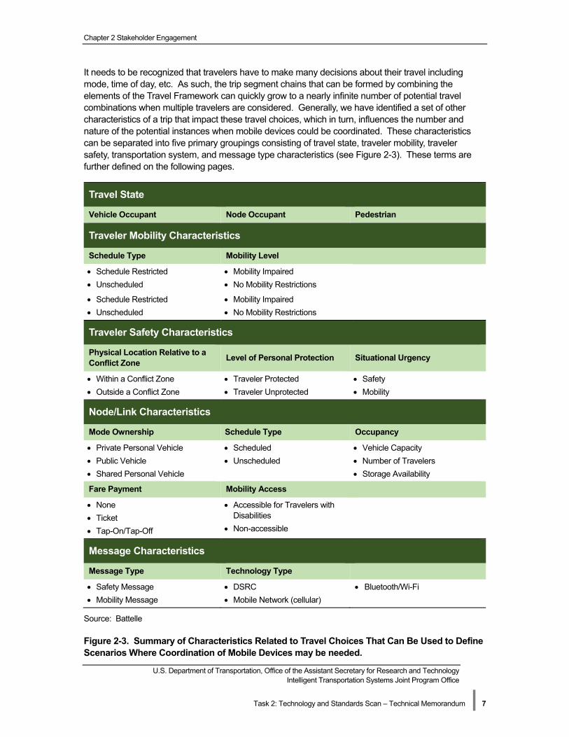
It needs to be recognized that travelers have to make many decisions about their travel including mode time of day etc As such the trip segment chains that can be formed by combining the elements of the Travel Framework can quickly grow to a nearly infinite number of potential travel combinations when multiple travelers are considered Generally we have identified a set of other characteristics of a trip that impact these travel choices which in turn influences the number and nature of the potential instances when mobile devices could be coordinated These characteristics can be separated into five primary groupings consisting of travel state traveler mobility traveler safety transportation system and message type characteristics (see Figure 2-3) These terms are further defined on the following pages
Travel State
Vehicle Occupant Node Occupant Pedestrian
Traveler Mobility Characteristics
Schedule Type
Schedule Restricted
Unscheduled
Schedule Restricted
Unscheduled
Mobility Level
Mobility Impaired
No Mobility Restrictions
Mobility Impaired
No Mobility Restrictions
Traveler Safety Characteristics
Physical Location Relative to a Conflict Zone
Level of Personal Protection Situational Urgency
Within a Conflict Zone Traveler Protected Safety
Outside a Conflict Zone Traveler Unprotected Mobility
NodeLink Characteristics
Mode Ownership Schedule Type Occupancy
Private Personal Vehicle Scheduled Vehicle Capacity
Public Vehicle Unscheduled Number of Travelers
Shared Personal Vehicle Storage Availability
Fare Payment Mobility Access
None Accessible for Travelers with
Ticket Disabilities
Tap-OnTap-Off Non-accessible
Message Characteristics
Message Type Technology Type
Safety Message DSRC BluetoothWi-Fi
Mobility Message Mobile Network (cellular)
Source Battelle
Figure 2-3 Summary of Characteristics Related to Travel Choices That Can Be Used to Define Scenarios Where Coordination of Mobile Devices may be needed
|
Chapter 2 Stakeholder Engagement
The following provides additional information on each of the five groups of characteristics
Travel State
Travel state describes the orientation of a traveler with respect to both vehicles and structure types A specific designation applies to each phase of the trip chain (node or link) from origin to destination A link is a phase in which the traveler is in transit A node is a phase in which the traveler is located at a transition point such as a bus stop or train station The following travel states have been identified
Vehicle Occupant
The state of traveling within any mode (with the exception of pedestrian)
Node Occupant The state in which a traveler is enclosed within a structure and protected from vehicular travel This includes an origin destination or transfer point between any two vehicle types within a trip chain (such as a train station or bus stop)
Pedestrian The state in which a traveler is traveling by foot contained by neither a vehicle nor a structure
Traveler Mobility Characteristics
Traveler mobility characteristics describe mobility restrictions unique to a traveler that are typically unchanged throughout an entire trip chain They do not vary with time mode or location For example a weekday commuter who requires a wheelchair will experience the same limitations throughout an entire trip Traveler mobility attributes do however impact traveler decisions within a trip by determining mode and time choices Traveler mobility attributes include the following
Schedule
Schedule Restricted
A traveler with a schedule-restricted trip is dependent upon an on-time arrival such as a commute travel time reliability plays a key role in departure time and mode choice
Type Unscheduled
A traveler with a non-schedule restricted trip such as a recreational trip such a traveler is not dependent upon an on-time arrival allowing for a greater range of travel choices and a more flexible departure time
Mobility
Requires additional disability services
A traveler with mobility restrictions such limited motor function or vision impairment will be limited to modes of travel and transfer points that can accommodate his or her disability(ies)
Level Does not require additional disability services
A traveler without mobility restrictions can make trip decisions without this consideration
US Department of Transportation Office of the Assistant Secretary for Research and Technology Intelligent Transportation Systems Joint Program Office
Task 2 Technology and Standards Scan ndash Technical Memorandum | 8
Chapter 2 Stakeholder Engagement
Traveler Safety Characteristics
Traveler safety characteristics describe the safety characteristics experienced by a traveler at each moment in time during a trip These characteristics can vary both between nodeslinks and within them For example a traveler on foot might experience varying levels of exposure to vehicles (ie in a crosswalk vs on a sidewalk) even though the traveler remains a pedestrian for the duration of the trip Traveler safety attributes include the following
Physical Location Relative to a Conflict Zone
Within a Conflict Zone
A traveler is located within the zone of vehicular travel where a vehicle-pedestrian collision could occur such as a crosswalk or parking lot
Outside a Conflict Zone
A traveler is located outside of a vehicular travel zone where vehicle-pedestrian collisions are extremely unlikely such as an office building or sidewalk
Level of Personal Traveler Protected
A traveler is contained within a building or vehicle which offers protection from a potential vehicle collection
Protection Traveler Unprotected
A traveler is unprotected from potential of a vehicle collision
Situational Urgency
Safety Safety concerns are considered to be an urgent priority necessitating immediate action Transmittal by means of a low latency message is required to ensure adequate reaction time
Mobility Mobility concerns are less urgent in nature allowing for transmittal by any available means of communication
US Department of Transportation Office of the Assistant Secretary for Research and Technology Intelligent Transportation Systems Joint Program Office
Task 2 Technology and Standards Scan ndash Technical Memorandum | 9
Chapter 2 Stakeholder Engagement
Transportation System Characteristics
Transportation System characteristics describe the characteristics that pertain to each ldquonoderdquo (a phase in which the traveler is located at a transition point) and ldquolinkrdquo (a phase in which the traveler is in transit) within a trip chain These attributes can vary both between nodeslinks and within them For example a traveler by bus may experience varying degrees of bus occupancy between trip links Nodelink attributes include the following
Mode Ownership
Private Personal Vehicle
A privately owned vehicle such as a personal automobile or bicycle which affords its user the flexibility to start and end trips whenever it is convenient and wherever there is capacity for the vehicle type
Public Vehicle A public agency owned vehicle such as a transit bus or commuter rail which runs on a set schedule restricting user flexibility and node location
Shared Personal Vehicle
A publicly or privately owned vehicle such as a car share or bike share that is rented for a designated time period While users have additional flexibility in schedule and route node location and capacity is limited at certain times
Schedule Type
Scheduled A mode that runs on a set schedule or timetable restricting the flexibility of users dependent upon an on-time arrival
Unscheduled A demand-responsive mode that operates based on the needs of an individual user
Vehicle Capacity The total number of travelers a specific vehicle can carry
Occupancy Number of Travelers The current number of travelers a vehicle is carrying
Storage Availability The capacity for a vehicle to accommodate ancillary travel devices such as bicycles or wheelchairs
None A mode that is designated as free or does not require fare payment such as a personal vehicle
Fare Payment Ticket
A mode that requires the purchase of a fare (either before or after boarding the vehicle) such as a bus or commuter rail
Tap-OnTap-Off A mode that requires the purchase of a fare prior to entering the station or boarding the vehicle and a second time in order to exit the vehicle or station
Mobility Access
Accessible for Travelers with Disabilities
A mode that provides facilities for people with disabilities such as wheelchair lifts and priority seating
Non-accessible A mode that does not accommodate use by disabled travelers
US Department of Transportation Office of the Assistant Secretary for Research and Technology Intelligent Transportation Systems Joint Program Office
Task 2 Technology and Standards Scan ndash Technical Memorandum | 10
Chapter 2 Stakeholder Engagement
Message Characteristics
Traveler mobility traveler safety and nodelink characteristics combine to inform the considerations that will determine the message type appropriate for a given scenario Like traveler safety and nodelink characteristics message characteristics are unique to a moment in the trip chain and will vary by needs and conditions
Message Type
Safety Message
Safety messages are considered to be high priority The speed with which safety messages are transmitted necessitates a low latency level thus limiting the technology that can be used for transmission
Mobility Message Mobility messages are considered to be lower in priority allowing transmission by a range of technologies from low to high latency
Communication Technology Type
Dedicated Short-Range Communications (DSRC)
DSRC has a short range and low latency making it the only method currently used to exchange safety messages DSRC can also be used to exchange mobility messages
Mobile Network Mobile network messages have a wide range and high latency making the technology ideal for exchanging mobility messages across a wide area such as a metropolitan area
Near Field Communication (NFC)
NFC has a very short range (1-2 inches) making it ideal for facilitating payments via a tap-ontap-off system identified through an NFC tag read for public transportation facilities such as a transit station
Bluetooth Bluetooth has a local range and high latency making the technology ideal for exchanging mobility messages across a localized area such as a transit station
Wi-Fi Wi-Fi has a short range and high latency making the technology ideal for exchanging mobility messages across a localized area such as a transit station
US Department of Transportation Office of the Assistant Secretary for Research and Technology Intelligent Transportation Systems Joint Program Office
Task 2 Technology and Standards Scan ndash Technical Memorandum | 11
Chapter 2 Stakeholder Engagement
As these characteristics change for each traveler and potentially for each trip so too will the choices of travel modes and resulting opportunities for coordination of mobile devices In particular each gold-colored box in Figure 2-2 is expected to result in at least one type of message and potentially more as the contextual nature of the characteristics defined above are considered For example consider the gold-box in the ldquoTravel State Node Occupantrdquo row labeled ldquo2 Wait to Boardrdquo As described in the figure there is a coordination opportunity for the mobile devices of the persons waiting to board to coordinate either among themselves or with the node (ie bus stop) However in terms of messages being distributed this could result in several different types of messages to facilitate this coordination including
Basic Position Message ndash this type of message would provide a location of each mobile device that could be used to determine that they are ldquoeligiblerdquo for coordination
Communication Protocols Available ndash this type of message would provide a summary of the communication protocols operating system etc available to the mobile device and indicate which protocol is to be used for coordinating with other mobile devices vehicles and nodes
Mobile Device State ndash this type of message would provide information on the state of the mobile device as it relates to mobility and safety (ie in a coordinated state in uncoordinated state not available for coordination etc)
Coordination RequestResponse ndash this type of message would be used by the mobile devices to initiate and implement coordination with each other or with a vehicle andor node
De-Coordination RequestResponse ndash this type of message would be used by the mobile devices to cease coordination
At the same time we would expect there to be different messages that would convey information specific to mobile devices such as
Personal Safety Message ndash this type of message would provide information that would relate to safety and would include elements such as state of the traveler (ie stationary moving) number of travelers (if this message is being coordinated among several mobile devices) and even additional information such as projected path etc
Personal Mobility Message ndash this type of message would provide information on the traveler such as mobility needs schedule constraints etc
US Department of Transportation Office of the Assistant Secretary for Research and Technology Intelligent Transportation Systems Joint Program Office
Task 2 Technology and Standards Scan ndash Technical Memorandum | 12
US Department of Transportation Office of the Assistant Secretary for Research and Technology Intelligent Transportation Systems Joint Program Office
Task 2 Technology and Standards Scan ndash Technical Memorandum | 13
Chapter 3 Technology Scan
Chapter 3 Technology Scan
This Chapter presents the findings of the technology scan and presents possible sources and mediums for safety and mobility message exchange utilizing mobile devices Additionally these same devices will be assessed for their ability to exhibit specific characteristics about their current use state as it supports the identification of a travelerrsquos current state andor mode While these findings are extensive they are not exhaustive of every possible technology that exists today Each subsection addresses assumptions and boundaries of the research
There are many components within mobile devices vehicles and infrastructure that allow user data to be captured processed and communicated As was discussed in Chapter 2 of this report a traveler is considered to be in one of three mutually exclusive states a vehicle a node or as a pedestrian The ability to differentiate between these states is important in the context of coordinating and broadcasting messages Sensor data and communication device connection data being captured can be used to infer the current travel state when state transitions occur and to communicate this information among other devices vehicles and infrastructure
Mobile Device Communication and Sensor Technologies
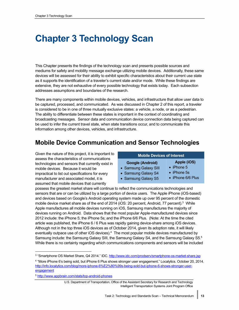
Given the nature of this project it is important to assess the characteristics of communications technologies and sensors that currently exist in mobile devices Because it would be impractical to list out specifications for every manufacturer and associated model it is assumed that mobile devices that currently possess the greatest market share will continue to reflect the communications technologies and sensors that are or can be utilized by a large portion of device users The Apple iPhone (iOS-based) and devices based on Googlersquos Android operating system made up over 95 percent of the domestic mobile device market share as of the end of 2014 (iOS 20 percent Android 77 percent)3 While Apple manufactures all mobile devices running on iOS Samsung manufactures the majority of devices running on Android Data shows that the most popular Apple-manufactured devices since 2012 include the iPhone 5 the iPhone 5s and the iPhone 66 Plus (Note At the time the cited article was published the iPhone 6 6 Plus was rapidly gaining device-share among iOS devices Although not in the top three iOS devices as of October 2014 given its adoption rate it will likely eventually outpace use of other iOS devices)4 The most popular mobile devices manufactured by Samsung include the Samsung Galaxy SIII the Samsung Galaxy S4 and the Samsung Galaxy S55
While there is no certainty regarding which communications components and sensors will be included
Mobile Devices of Interest
Google (Android) Samsung Galaxy SIII Samsung Galaxy S4 Samsung Galaxy S5
Apple (iOS) iPhone 5 iPhone 5s iPhone 66 Plus
3 ldquoSmartphone OS Market Share Q4 2014rdquo IDC httpwwwidccomprodservsmartphone-os-market-sharejsp 4 ldquoMore iPhone 6rsquos being sold but iPhone 6 Plus shows stronger user engagementrdquo Localytics October 20 2014 httpinfolocalyticscomblogmore-iphone-6E28099s-being-sold-but-iphone-6-shows-stronger-usershyengagement 5 httpwwwappbraincomstatstop-android-phones
Chapter 3 Technology Scan
in future mobile devices these representative devices should provide a starting point from which assumptions can be made regarding the capabilities of current mobile devices
As will be detailed in the following subsections components from these six mobile devices are assessed showing which communications technologies and sensors are available to be utilized to establish the personal mobility state determine appropriate times for coordination and to transmit and receive mobility and safety-related messages tailored for the specific current state
Mobile Device Communications Technologies
Of the mobile devices researched the communications devices that could be leveraged include Bluetooth Wi-Fi NFC DSRC and the mobile device cellular network These communications technologies can be leveraged in two different ways First communications technologies can be used to send raw sensor data or processed sensor data to operators or other users of the network Second the ability for devices to communicate allows a device to recognize when it is in the presence of another device ndash which can be utilized (in addition to sensor data) to infer travel state While these communications by themselves can provide a great deal of information additional benefit is derived from the fact that they are all contained within a single mobile device and can be attributed to a single user of the transportation system Table 3-1 provides a high-level overview of key components of each technology
US Department of Transportation Office of the Assistant Secretary for Research and Technology Intelligent Transportation Systems Joint Program Office
Task 2 Technology and Standards Scan ndash Technical Memorandum | 14
US Department of Transportation Office of the Assistant Secretary for Research and Technology Intelligent Transportation Systems Joint Program Office
Task 2 Technology and Standards Scan ndash Technical Memorandum | 15
Table 3-1 Mobile Device Communication Technology Overview
40
Type Description
Supports data transmission of up to 100 meters at a maximum rate of 1 Mbps
Unique device identifiers (MAC) may be obtained during pairing process without Bluetooth lsquoClassicrsquo
having to complete the pairing
Supports TCIPIP and UDP formats however Serial Port Profile (SPP) is the most common method used for data interchange
Similar range but has reduced transmission rates as compared with lsquoclassicrsquo Bluetooth the emphasis being on decreased power consumption
Bluetooth LE Designed for applications that do not need to exchange a lot of information
Supports IPv66LoWPAN as the primary mechanism for data interchange
Supports Infrastructure and Ad-Hoc Modes
Unique device identifiers may be obtained without a Wi-Fi connection (SSID) Wi-Fi
Supports data transmissions of up to 1500 ft at a maximum rate of 54 Mbps
Available with encryptionsecurity or open
Short-range communication (typically 1-2 inches)
NFC Facilitates contactless mobile payments
Not available on all iOS mobile devices
Low-latency high-reliability
DSRC Specifically designed for vehicular environment
Not currently available on mobile devices
Providers have network API features that may be used to obtain location information Mobile Network
terminal status and service provider
Chapter 3 Technology Scan
Source Battelle
While the protocols and use cases of Bluetooth and Wi-Fi are very distinct they could be leveraged in similar ways Both Bluetooth and Wi-Fi can be used to send data either collected from the devicersquos sensors or from user input to transportation operators and other users Furthermore unique device identifiers such as a media access control (MAC) address or service set identifier (SSID) can be obtained even if there is not an active Wi-Fi or Bluetooth connection Bluetooth beacons and Wi-Fi devices on vehicles such as a car or bus is one consideration that may facilitate the identification of a traveler carrying a mobile device within the confines of the vehicle The mobile devicersquos Bluetooth or Wi-Fi device however must be enabled for detection All of the assessed devices utilize Bluetooth Version 40 Bluetooth is further divided up into three classes Class 1 devices use the most power and can transmit a signal up to 100 meters Class 2 devices use less power and transmit a signal up to 30 meters and Class 3 devices can transmit signals around a few meters6 Bluetooth transmitters in mobile devices tend to be Class 2 devices
6 ldquoTop Android Phonesrdquo AppBrain Stats Updated April 2 2015 httpwwwappbraincomstatstop-androidshyphones
US Department of Transportation Office of the Assistant Secretary for Research and Technology Intelligent Transportation Systems Joint Program Office
Task 2 Technology and Standards Scan ndash Technical Memorandum | 16
Chapter 3 Technology Scan
One of the more recent advances in Bluetooth is Bluetooth Low Energy (BLE) which uses an extremely small amount of energy in order to broadcast a short-range (typically a few meters) Bluetooth signal Standard coin cell batteries are able power BLE devices for years This allows the technology to be applied in small devices such as pedometers glucose monitors and beacons7
Currently beacons are predominately used to interact with or advertise to Bluetooth-enabled mobile device users (who opt in)8 However a device could potentially be used to detect when a beacon (or another Bluetooth device) is within its range and the relative strength of the signal could be assessed to estimate the distance between the mobile device and the beacon Such a capability could be utilized to gauge whether a traveler is inside of a public transit vehicle or has left the vehicle or to assess a travelerrsquos location in an urban environment where GPS signal may not be as reliable
Wi-Fi which for purposes of this analysis refers to the IEEE 80211 set of standards can communicate at distances reaching over 1500 ft and at speed approach 54 Mbps A recent enhancement to Wi-Fi is MIMO MIMO (or multiple input multiple output) is a Wi-Fi and mobile signal antenna technology where multiple antennas are used to transmit data to a device Advantages include the ability to transmit data more rapidly and reduce the likelihood of impacts due to obstructions which result in signal fading cut-out and intermittent reception9 While multipath interference typically reduces wireless data transfer speeds MIMO takes advantage of this effect by combining data streams from different paths at different times to increase the ability of the receiver to capture the signal MIMO is included in all wireless communication technologies defined by IEEE 80211n and newer which indicates the technology is present on all Wi-Fi chips in the mobile devices evaluated10
One of the emerging uses of Wi-Fi is to establish ldquoad-hocrdquo communications or networks to exchange information and or provide connectivity to the Internet or other networks One common usage of this technology is to use a Wi-Fi direct connection for streaming of video andor audio dynamically from a mobile device to a display screen (eg television) which is generally characterized as ldquoMiracastingrdquo Other usages include dynamic discovery of Wi-Fi availability or ldquoWi-Fi Awarerdquo and providing bridging for Wi-Fi networks (ie ldquoWi-Fi Passpointrdquo)
Near Field Communication (NFC) is a short-range communications technology (typically 1shy2 inches) when combined with an electronic payment system is becoming an increasingly accepted method for making payments via mobile devices NFC technology has only recently become widely available across both Android and iOS smartphones with the release of the iPhone 6 6 Plus However NFC technology is expected to remain a prevalent component of future mobile devices as significant investments by mobile device providers in applications such as Google Wallet and Apple Pay (with Passbook) which are designed to facilitate mobile device-based payments continue to occur Several transit systems had or are currently testing pilot projects to test the feasibility of mobile device-based payments11 While there are no examples of a full-scale implementation of an NFC mobile payment solution within the transit community there is movement and research projects that suggest that this transition will eventually occur Washington DCrsquos Metro Payment Pilot program is an
7 ldquoBluetooth Smart (Low Energy) Technologyrdquo Bluetoothreg Developer Portal httpsdeveloperbluetoothorgTechnologyOverviewPagesBLEaspx 8 ldquoBluetooth Beaconsrdquo httpbluetoothbeaconscom 9 ldquoMIMO (multiple input multiple output) TechTarget httpsearchmobilecomputingtechtargetcomdefinitionMIMO 10 ldquoWireless Networking What is Multiple-Input Multiple-Output (MIMO)rdquo Intel httpwwwintelcomsupportwirelesssbcs-025345htm 11 ldquoPayment Pilotrdquo WMATA Metro httppaymentpilotwmatacomabout and ldquoTap Riderdquo NJ Transit httpwwwnjtransitcomvarvar_servletsrvhdnPageAction=TapRideTo
US Department of Transportation Office of the Assistant Secretary for Research and Technology Intelligent Transportation Systems Joint Program Office
Task 2 Technology and Standards Scan ndash Technical Memorandum | 17
Chapter 3 Technology Scan
example of an NFC payment system that is expected to eventually replace the current SmartCard system12 An individualrsquos transition onto or off of a transit vehicle (for a tap-ontap-off system) can be identified through an NFC tag read embedded in their mobile device
Dedicated Short Range Communications (DSRC) is a low-latency high-reliability two-way wireless communications tool specifically architected for exchanging messages in a vehicular environment (eg when vehicle approaching one-another or approaching a fixed access point at a high rate of speed and having only a limited period of optimal information exchange) Operating in the dedicated 59 GHz band the messages are transmitted vehicle-to-vehicle (V2V) and between vehicles and the infrastructure (V2I) While not a component of todayrsquos mobile devices DSRC has previously been tested in mobile devices from 2007 to 2009 by OKI OKI integrated DSRC devices into mobile phones to increase safety between DSRC-equipped vehicles and pedestrians carrying DSRC-equipped mobile devices A DSRC attachment was also developed for non-DSRC phones13 The device would alert both pedestrians and drivers of a potentially impending collision14 The DSRC radio used consumed 10 mW of power and could send and receive signals up to several hundred meters15
In 2013 Honda was able to use a DSRC-enabled mobile device in a similar fashion A warning was displayed to the driver and an alert sent to the pedestrianrsquos mobile device when a collision was impending16 Device makers are also beginning to support the IEEE 80211p specification referred to as Wireless Access in Vehicular Environments (WAVE) alone or in combination with other Wi-Fi and wireless specification Redpine Signalrsquos pLink module support 80211p along with 80211abgn Bluetooth 40 and Zigbeereg17 Arada Systems is also making an add-on lsquobackpackrsquo that contains a separate battery-powered DSRC radio that can pair with existing mobile device18
With respect to personal mobility messages the integration of a DSRC radio into a mobile device would greatly enhance the communications capabilities of mobile devices With the many benefits that it could provide as evidenced by the OKI and Honda projects and the commercial offerings from Redpine Signal and Arada Systems the inclusion of DSRC in future mobile devices is a plausible scenario that should be given consideration
There may also be potential for utilizing DSRC for the communication of mobility messages that are generated by a mobile device This would require information to be transmitted between the mobile device and the DSRC radio installed in a vehicle In-vehicle DSRC radios are discussed later in this chapter
12 ldquoPay for Metro with your smartphone or watch Testing starts soonrdquo Metro Payment Pilot October 14 2014 httppaymentpilotwmatacompay-for-metro-with-your-smartphone-or-watch-testing-starts-soon 13 ldquoWorldrsquos First DSRC Inter-vehicle Communication Attachment for Mobile Phones January 8 2009 httpwww3gcoukPRJan2009Worlds_First_DSRC_Intershyvehicle_Communication_Attachment_for_Mobile_Phones_3Ghtm 14 ldquoDSRC on mobile devicesrdquo Road Talk July 23 2008 httpsroadtalkwordpresscom20080723dsrc-onshymobile-devices 15 ldquoOki Exhibits DSRC-based Human-vehicle Communication Devicerdquo Nikkei Technology July 23 2008 httptechonnikkeibpcojpenglishNEWS_EN20080723155249 16 ldquoHonda Demonstrates Advanced Vehicle-to-Pedestrian and Vehicle-to-Motorcycle Safety Technologies Honda August 28 2013 httpwwwhondacomnewsandviewsarticleaspxid=7352-en 17 RS9113 p-Link Module Family April 10 2015 httpwwwredpinesignalsusModulesInternet_of_ThingspshyLink_FamilyRS9113-NBZ-D2Pphp 18 Locomate ME (Portable DSRC Unit) April 10 2015 httpwwwaradasystemscomlocomate-me
US Department of Transportation Office of the Assistant Secretary for Research and Technology Intelligent Transportation Systems Joint Program Office
Task 2 Technology and Standards Scan ndash Technical Memorandum | 18
Chapter 3 Technology Scan
Mobile Device Cellular Network (3G 4G LTE) can be leveraged to transmit data between the mobile device and other users and transportation service providers For the purpose of this project only 3G communications technologies and newer will be considered It is also common knowledge that different carriers utilize different technology on their mobile networks When multiple cell towers are visible from a single device it is possible to triangulate (multilateration) the devicersquos location based on the signal strength from each of the towers Using this technique may be useful when GPS signal is not available or reliable and when other communications technologies cannot be established to estimate position Additionally mobile network providers such as Verizon provide a network API If the user grants consent these APIs can be leveraged to perform tasks such as sending text and multi-media messages and obtaining information about an individual mobile devicersquos location terminal status (reachableunreachable) and service providercarrier19 The devicersquos location is either reported as coarse (indicating the location estimate is based off of cell tower triangulation) or precision (GPS trace) The Verizon Location Agent must be installed on the device for precision information to be obtained20
Summary of Communications Devices
Table 3-2 provides a summary of the above discussed communication technology characteristics and includes some specificity not discussed above such as the frequency power consumption transfer rate and range This table lists associated standards frequencies and maximum data transfer rates for each communication technology While the majority of these communication technologies could serve as a medium for message dissemination a trade-off analysis still needs to be performed This analysis of the benefits and issues of each including down select will be completed in future tasks associated with this project
19 ldquoSupported Verizon Network APIsrdquo Verizon Developer Community httpdeveloperverizoncomcontentvdcenverizon-tools-apisverizon_apisnetwork-apinapi_supported_apihtml 20 ldquoPrecision Location Fix Requirementsrdquo Verizon Developer Community httpdeveloperverizoncomcontentvdcenverizon-tools-apisverizon_apisnetwork-api-directshydevelopmentnapi_technical_resourcesnapi_techresources_agps_fixhtml
US Department of Transportation Office of the Assistant Secretary for Research and Technology Intelligent Transportation Systems Joint Program Office
Task 2 Technology and Standards Scan ndash Technical Memorandum | 19
Chapter 3 Technology Scan
Table 3-2 Characteristics of Communication Technologies ndash Means of Transmission
Hardware Latency Network
Standard Frequency
(US)
Power Consrsquoption
(max)
Max Data Transfer Rate
Range (unobstructed)
Bluetooth
Bluetooth 40 6ms (unconn)
3ms (minimum)
IEEE 802151 24-2485 GHz ~36mA 1 Mbps 100m
Wi-Fi
Wi-Fi 80211ac
Unavail IEEE 80211ac 5GHz ~36mA 1300 Mbps
Wi-Fi 80211n Unavail IEEE 80211n 2412-2472GHz
5180-5825GHz
Unavail 600 Mbps 820
Wi-Fi 80211g Unavail IEEE 80211g 2412-2472GHz Unavail 54 Mbps 330
Wi-Fi 80211b Unavail IEEE 80211b 2412-2472GHz Unavail 11 Mbps 330
Wi-Fi 80211a Unavail IEEE 80211a 5180-5825GHz Unavail 54 Mbps 100
NFC
NFC Low ISO 13157
ISO 14443
1356MHz Unavail 424kbps 1-2 in
DSRC
DSRC Very Low IEEE 1609
IEEE 80211p
585-5925 GHz 750mW (288 dBm)
Unavail Unavail
Mobile Network
CDMA2000 1xEV-DO
(3G)
CDMA2000 1xEV-DO
Rev-A (3G)
CDMA2000 1xEV-DO
Rev-B (3G)
Unavail
Unavail
Unavail
CS0024-0
CS0024-100
CS0024-200 CS0024-300 CS0024-400
CS0024-500 CS0024-A
CS0024-B
80085017001 900 MHz
Unavail
Unavail
Unavail
25 Mbps (d) 153 kbps (u)
31 Mbps (d) 18 Mbps (u)
93 Mbps (d) 54 Mbps (u)
Unavail
Unavail
Unavail
UMTS (WCDMA) (3G)
HSPA (3G)
HSPA+ (3G)
Unavail
Unavail
Unavail
3GPP ndash 25 series 3GPP
TS 25101 3GPP TS
25102
1710-1755 MHz
2110-2155 MHz
Unavail
Unavail
Unavail
384 kbps
14 Mbps (d) 5 Mbps (u)
84 Mbps (d)
108 Mbps(u)
Unavail
Unavail
Unavail
LTE (3G)
LTE Advanced (4G)
Unavail
Unavail
3GPP ndash 36 series
700750800
85017002100 1900 2500
2600 MHz
Unavail
Unavail
300 Mbps (d) 75 Mbps (u)
1 Gbps
Unavail
Unavail
Not available in current mobile devices
Typical speeds are much lower particularly for mobile network communications
Range varies as a function of the strength of the signal source
Source Battelle
Chapter 3 Technology Scan
Mobile Device Sensor Technologies
A key tenant of being able to successfully coordinate messages and transition between travel states is the belief that each state of travel exhibits a unique set of characteristics In addition to the various communication technologies available and previously discussed mobile devices also possess sensors that have the ability to measure a whole host of data which may be subsequently used to quantify these characteristics and support the identification of the current travel state as well as transitions between states These sensors can be divided into two categories hardware and software (virtual) Hardware sensors report raw data from a particular sensor on the device while software sensors take data from one or more hardware sensors to provide an imputed output Table 3-3 lists and provides a brief description of the commonly available hardware and software sensors found in the reviewed devices Detailed discussions of how these sensors may contribute to the goals of this project follow
Table 3-3 Hardware and Software Mobile Sensor Descriptions
Mobile Hardware Sensors
(raw data)
Accelerometer
Gyroscope
Magnetometer
Light Sensor
Proximity
Thermometer
Hygrometer
Barometer
Position
Microphone
Camera
Measures the acceleration force on the device along three axes
Measures the rate of rotation of the device along three axes
Measures the geomagnetic field surrounding the device along 3 axes
Measures ambient light
Measures the distance between the sensor and a nearby object
Measures the temperature of air surrounding the device
Measures the humidity of the air surrounding the device
Measures the pressure of air surrounding the device
Measures latitude longitude elevation and time (UTC) and a function of a GPS
Capture audio using built-in microphone
Capture video or still images using built in charge-coupled device typically both forward and rear-facing
Mobile Software
Sensors (imputed
data)
Gravity
Linear Acceleration
Rotation Vector
Speed
Heading
Step Detector Counter
Estimates the force of gravity along the three axes
Estimates the acceleration force of the device along three axes excluding gravity
Describes the orientation of the screen of a mobile device
Output of GPS based on successive collection of latlongelav Points
Output of GPS based on successive collection of latlongelav Points
Uses accelerometer data to estimate when a step has been taken
Commonly found in mobile devices
Source Battelle
US Department of Transportation Office of the Assistant Secretary for Research and Technology Intelligent Transportation Systems Joint Program Office
Task 2 Technology and Standards Scan ndash Technical Memorandum | 20
US Department of Transportation Office of the Assistant Secretary for Research and Technology Intelligent Transportation Systems Joint Program Office
Task 2 Technology and Standards Scan ndash Technical Memorandum | 21
Chapter 3 Technology Scan
Accelerometer The acceleration attributes of walking are unique when compared to other modes During trips in a personal automobile bus or train acceleration data is expected to reflect an output waveform that is fairly flat and lengthy duration and can easily be distinguished from the high-frequency accelerations of walking This high-frequency oscillating acceleration can be detected by the accelerometer sensor and analyzed to detect when a step has been taken ndash see step detector below
Gyroscope Gyroscopes are used to detect rotational motion along the three axes of the mobile device When used in combination with data from the accelerometer gyroscope data can be used to provide more precise estimates of the devicersquos orientation linear acceleration and gravity vector ndash described below
Light Sensor The light sensor is usually located on the screen side of a mobile device and detects brightness of light One use of this sensor is to automatically adjust the screen brightness to save energy when there is a low amount of ambient light and to increase brightness to improve visibility under high amounts of ambient light
Proximity A proximity sensor is located on the screen side of a mobile device and measures the distance to the nearest object Quite often these sensors are low resolution ndash only able to detect whether there is an object within 8 cm of the device or not However this low resolution works as intended ndash for turning the screen off when a person moves the phone up to their ear while on a call and on again when the phone is removed from the ear It is an event-based sensor changing in value only when an object moves into or out of range of the sensor
Thermometer and Hygrometer The thermometer measures the temperature of the ambient air and the hygrometer measures the humidity of the ambient air The thermometer sensor is not the same as the devices that detect the temperature of the processor and battery Given that the ambient temperature and humidity are measured within a device both readings have the ability to be affected by heat given off by other mobile device components sunlight andor body heat (if the device is in a pocket for example)
Barometer readings (unlike thermometer and hygrometer readings) are not affected by mobile device components or being indoors or outdoors At a given location over several hours pressure is expected to slowly vary as a result of normal weather patterns while weather fronts may result in more rapid pressure changes over shorter periods of time However over a relatively short period of time (the time it takes to go updown a flight of stairs or an elevator ride) the barometer in a moving device is accurate enough for detecting relative changes in altitude Knowledge of the devicersquos altitude could potentially indicate which floor of a building a device is on or which platform a user is standing on in a transit station with multiple-levels Such information could be useful for determining whether a user intends to transfer or exit a transit station
Global Positioning System Global Positioning Systems (GPS) have become ubiquitous in all present day mobile devices While technically a communications technology GPS is better viewed as pseudo-sensor as the device only receives data from the GPS satellites GPS can provide an estimate of latitude longitude and speed of the device as well as various measures of location reliability number of satellites accuracy position dilution of precision (PDOP) horizontal dilution of precision (HDOP) and vertical dilution of precision (VDOP) Given a reliable GPS signal a userrsquos location can be used in combination with other spatial characteristics of the transportation network to aid in identifying travel state as well as identify potential travel alternatives It is also possible that GPS can be used as a time source for the device as it is used by DSRC however most mobile devices continue to use the mobile network to set their time
Chapter 3 Technology Scan
Microphone A necessary component to support audio lsquophonersquo or voice-over-IP conversations and more recently voice-commands a microphone might be employed to listen to and possibly detect an environment in which the mobile device is currently located
Camera Sensors (most phones have two) that capture discrete or continuous images (video) in support of many of the features of modern mobile devices such as personal photographyvideography video calling social media content and code scanning Cameras have also been used crudely for transportation applications such as lane departure warnings
Gravity and Linear Acceleration Both the gravity and linear acceleration sensors are software sensors that utilize data coming from the accelerometer and gyroscope to make reliable estimates regarding the force of gravity along all three axes of the device (even while the device is moving) and the acceleration forces along all three axes excluding the force of gravity
Rotation Vector The rotation vector describes the orientation of the screen of a mobile device It is a software sensor that utilizes accelerometer and gyroscope data For example rotation vectors can be used to change the screen layout from a vertical orientation to a horizontal orientation when the phone is turned sideways
Speed Function of GPS that may be suitable for corroborating walk vs ride modes of a traveler
Heading Function of GPS that aid in determining path traveler is taking When compared to a map of area this function may be able to determine the location to lane crosswalk sidewalk other
Step Detector The step detector is a software sensor that utilizes accelerometer data to detect when a step has been taken Like the proximity sensor it is an event-based sensor When a step is taken the timestamp of the step is reported
Table 3-4 provides a summary of the characteristics of the sensors identified during this technology scan including both the frequency of the measurement and the cost in terms of power consumption to use the sensor Both of these characteristics are expected to be relevant when the design of the prototype is considered in later tasks however it is too premature to make any specific design recommendations at this time As such this information if presently included for the purposes of complete documentation and for the benefit of future use of this research
US Department of Transportation Office of the Assistant Secretary for Research and Technology Intelligent Transportation Systems Joint Program Office
Task 2 Technology and Standards Scan ndash Technical Memorandum | 22
Chapter 3 Technology Scan
Table 3-4 Characteristics of Communication Technologies ndash Sensor Types
Sensor Type Max Data Frequency
(Hz)
Typical Range
Units Power
Consumption (active)
sors
n
Accelerometer
Gyroscope
Magnetometer
100
100
100
plusmn196133
plusmn8726646
plusmn1200
ms2
rads2
microT
025
61
60
Har
dwar
e S
e Light Sensor
Proximity^
Thermometer
Hygrometer
Barometer
100
Event-based
1
1
15
0-60000
0-8
-30-100
0-100
300-1100
lux
cm (may vary low res)
⁰C
mBar (or mmHg)
075
075
03
03
10
rs Gravity 100
100
100
Event-Based
plusmn196133
plusmn196133
plusmn1
NA
ms2
ms2
none
none
1235
1235
1235
025
Sen
so Linear Accel
war
eS
oft
Rotation Vector
Step Detector^
^Event based sensors ndash only change when an event occurs (eg step taken)
Source Battelle
Table 3-5 lists the availability of different hardware sensors in the six mobile devices of interest being used to assess communications technologies Where possible the hardware manufacturer and model were identified and listed Accelerometers gyroscopes magnetometers proximity sensors and light sensors have been included in mobile devices over the last three years These five sensors have become an integral component of many of the basic functionalities of mobile devices (eg rotating screen turning screen onoff automatically while on a call auto-adjust brightness) not to mention the functionalities of certain applications (eg games compass) It is highly likely these sensors will continue to be included in almost all mobile devices
More recently barometers thermometers and hygrometers have been included on certain mobile devices Air pressure sensors in phones allow more accurate altitude estimations to be made (compared to GPS) may provide data for crowd-sourced weather applications and are used in healthfitness apps The Galaxy S III (May 2012) and the iPhone 6 6 Plus (September 2014) are the first generation of phones released by Samsung and Apple (respectively) that contain a barometer Samsung has co ntinued the inclusion of this sensor on the Ga laxy S4 a nd S5 and announcements indicate a barometer will be included on the Galaxy S6 Apple has not released a phone since the iPhone 6 6 Plus and to date there has not been no official announcement regarding sensors that will be included in the next offering from Apple
US Department of Transportation Office of the Assistant Secretary for Research and Technology Intelligent Transportation Systems Joint Program Office
Task 2 Technology and Standards Scan ndash Technical Memorandum | 23
Chapter 3 Technology Scan
US Department of Transportation Office of the Assistant Secretary for Research and Technology Intelligent Transportation Systems Joint Program Office
Task 2 Technology and Standards Scan ndash Technical Memorandum | 24
Table 3-5 Sensor Hardware in Mobile Devices of Interest to this Project
Mobile Light Proximity Accrsquometer Gyroscope Magnetometer Therrsquometer Hygrometer Barometer
Device Sensor Sensor
In device In device No No
In device Samsung STM STM STM
(OEM (OEM (OEM Galaxy S III LSM330DLC LSM330DLC AKM8975 unknown) unknown) unknown)
STMicroelectro CapellaSTMicroelectronics Yamaha MAXIM Sensirion Sensirion BoschSamsung nics Microsystems
Galaxy S 4 K330 YAS532 MAX88920 SHTC1 SHTC1 BMP180 K330 CM3323
In device In device Samsung Invensense Invensense Yamaha
No No STM
(OEM (OEM Galaxy S 5 MPU-6500 MPU-6500 YAS532B LPS25Hunknown) unknown)
STMicroelectro In device In device Apple STMicroelectronics In device (OEMnics (OEM (OEM
L3G4200D unknown) iPhone 5 LIS331DLH unknown) unknown) No No No
In device In device Apple Bosch BMA220 STM AKM AK8963 (OEM (OEM
iPhone 5s unknown) unknown) No No No
InvenSense In device In device Apple InvenSense No No
BoschMP67B AKM AK8963C (OEM (OEM MP67B BMP280iPhone 6
Bosch BMA280 unknown) unknown)
Where possible the hardware manufacturer and model were identified and listed
Source Battelle
Chapter 3 Technology Scan
While it is impossible to forecast with certainty whether future mobile devices will contain barometers the evidence presented above suggests they will continue to be included Thermometer and hygrometer sensors have thus far only been included in the Galaxy S4 These two sensors were discontinued in the Galaxy S5 and the announcement for the Galaxy S6 indicates they will not be included on this model either None of the iPhone models have these two sensors nor are there indications Apple intends to include them in the future
For purposes of this project attempts will be made to use sensor technology that is available across all reviewed platforms such that the demonstration can show devices from multiple manufacturers and models
Mobile Device Operating Systems
In addition to the hardware components discussed the operating system (OS) is the ultimate enabler of the capability of each mobile device allowing the device to access the sensors and communications components and to execute software applications provided by the device maker the OS vendor and third-party applications While several operating systems currently exist the four major systems found in any significance include
Apple iOS
Google Android
Microsoft Windows Phone and
Blackberry OS
Based on 2014 end-ofshyyear reports (Q4 CY2014) Android and iOS have maintained the bulk of the market at 77 percent and 20 percent respectively Lagging behind is Windows at less than 3 percent Blackberry at less than 04 percent and all others combined at less than 05 percent21 In addition Android and iOS market shares are generally trending upward while Windows shares are generally flat and Blackberry shares are generally trending downward (as shown in Figure 3-1) Based on this
Source httpwwwidccomprodservsmartphone-os-market-sharejsp
Figure 3-1 Historic Data Shows Operating System Popularity Trends
US Department of Transportation Office of the Assistant Secretary for Research and Technology Intelligent Transportation Systems Joint Program Office
Task 2 Technology and Standards Scan ndash Technical Memorandum | 25
21 ldquoSmartphone OS Market Share Q4 2014rdquo IDC httpwwwidccomprodservsmartphone-os-market-sharejsp ldquoiPhone Firmware and iOS Historyrdquo Abouttech httpipodaboutcomodiphonesoftwaretermsafirmw_historyhtm ldquoApple iOS a brief historyrdquo The Telegraph httpwwwtelegraphcouktechnologyapple11068420Apple-iOS-a-brief-historyhtml ldquoA look into The History of iOS and its Featuresrdquo Hongkaia httpwwwhongkiatcomblogios-history ldquoA history of iOS design from iOS 1 to iOS 8rdquo Design Reviver September 9 2014 httpdesignrevivercomupdateshistory-ios-design
Chapter 3 Technology Scan
historical data only two device platforms were further considered the Samsung device running Android and the Apple iPhone devices running iOS
Software Releases and Fragmentation Both Android and iOS operating systems are updated on a regular basis which recently has been roughly once a year between major releases both operating systems issue minor updates to fix bugs and enhance various features
This fact is important because with every update fragmentation may occur As new software comes out both providers ldquoleave behindrdquo some of their older systems Apple closely manages updates to its iOS and associated proprietary data This results in less fragmentation across the products due to tighter control of both the hardware (as there is only one device manufacturer) and software Alternatively Googlersquos Android is run as open source software Updates may or may not be supported depending on the mobile device manufacturer and model as well as wireless carrier decisions As the market drives continued innovation this trend does not seem likely to change significantly nor can the true impact of these changes be predicted As noted herein Samsung had previously included support for temperature and humidity measurements on the Galaxy S4 platform only to drop this support on subsequent versions Similarly iOS revised their previous approach for making background location services available to third-party applications tightening the rules for the better but causing a significant amount of older applications to fail when attempting to run on a new version of the OS These are both highlighted as an example of how industry-trends and the device makers have ultimate control of the future of these devices a fact that needs to be considered as part of this analysis Only technologies that have been employed on multiple generations of a device makers products and hopefully across multiple device makers will be considered This information is critical not only in the determination of which existing sensors to leverage for data in the PSM and PMM but more so for future development of mobile devices natively supporting ITS endeavors for wide-spread adoption
Features of the various Operating Systems Table 3-6 summarizes several of the key lsquoapplicationsrsquo or services provided by each device maker with the latest version of their OS Detailed discussion on each follows These specific features are included as they have become a significant part of how people use their device and several of these could play a role in incorporating these devices into the connected vehicle environment
Table 3-6 Sample of Software Characteristics and Applications for Latest iOS and Android Systems
US Department of Transportation Office of the Assistant Secretary for Research and Technology Intelligent Transportation Systems Joint Program Office
Task 2 Technology and Standards Scan ndash Technical Memorandum | 26
Operating System Voice Assistant Maps Wireless Payment
Android 5 ldquoLollipoprdquo Google Now Google Maps Google Wallet
iOS8 Siri Apple Maps Apple Pay
Source Battelle
Chapter 3 Technology Scan
Voice Assistance Both operating systems have developed voice assistance which provides support in searching and initiating phone operations Siri (on iOS) is an on-command assistance application Google Now (on Android) also provides assistance on command However it is also designed to gather data on the user to pre-emptively offer information before being asked Voice Assistance is expected to continue to become more reliable and expand to support even greater capabilities (ie commands) in the future
MapsNavigation Both Android and iOS have GPS trackers and turn-by-turn navigational capabilities for pedestrians and motorists Google Maps was originally a key built-in feature provided with iOS from its inception until Apple removed the native application when it released iOS6 Apple Maps was initially poorly received resulting in the re-release of Google Maps as a third party application on the App Store Google has also provided Google Maps as part of Android Locational information may be controlled by the user on both operating systems If turned on both systems are able to track the user whether the screen is on or the app is running Maps and the associated trip planning are fully expected to play a significant role in the next generation of connected vehicle applications
Wireless Payment Capabilities Both Android and iOS have contactless payment applications (Google Wallet for Android and Apple Pay with Passbook for iOS) Android requires NFC and a passcode while iOS requires NFC and the touch ID Fingerprint Scanner technology Although both operating systems offer these applications on their latest releases Apple requires users to have the iPhone 6 6 Plus to enable the applications as these are the only Apple devices that contain NFC technology In addition to using NFC for contactless payment the Android Beam service allows users to tap phones to exchange data in the NFC Data Exchange Format (NDEF) andor to facilitate direct BluetoothWi-Fi connectivity between devices to transfer other types of data Applersquos AirDrop functions in a similar manner allowing for direct device-to-device data exchange using either BlueTooth or Wi-Fi Direct
US Department of Transportation Office of the Assistant Secretary for Research and Technology Intelligent Transportation Systems Joint Program Office
Task 2 Technology and Standards Scan ndash Technical Memorandum | 27
Chapter 3 Technology Scan
Source Battelle
Figure 3-2 A Timeline of the iOS and Android System Features22
22 ldquoiOS Versions and Features iOS History ndash The Evolving iPadiPhone OSrdquo Aboutteceh httpipadaboutcomodipad_detailsssiOS-Version-History-Featureshtm ldquoA Comparison of mobile operating systems know your OSrdquo October 24 2014 httpswwwgazellecomthehorn20141024a-comparison-of-mobile-operating-systemsshyknow-your-os ldquoAndroidrdquo httpswwwandroidcomintlen_ushistory ldquoA Brief History of Googlersquos Android Operating Systemrdquo IPWatchdog November 26 2014 httpwwwipwatchdogcom20141126a-brief-history-of-googles-android-operating-systemid=52285 and ldquoThe Android era From G1 to Lollipop July 2 2012 httpwwwcnetcomnewshistory-of-android
US Department of Transportation Office of the Assistant Secretary for Research and Technology Intelligent Transportation Systems Joint Program Office
Task 2 Technology and Standards Scan ndash Technical Memorandum | 28
Chapter 3 Technology Scan
Mobile Device Applications
There have been few technologies that have experienced such a rapid growth as todayrsquos smartphone These devices allow for tremendous innovation and rollout at unprecedented rates and scale including applications supporting personal safety mobility travel planning etc This section presents an overview of available mobile device applications used to enhance the traveler experience within a transportation network The applications presented are compatible with either the iOS andor Android (no other operating systems were considered) They have been included based on their potential to support or complement the exchange of PSM andor PMM within the connected vehicle environment While this list is not exhaustive it is intended to provide a diverse set of applications which may be utilized for enhancing the PSM and PMM in a connected vehicle environment
Table 3-7 documents several applications that were identified to have some relationship to transportation For each application the intended users the requirements for use a brief description of the user interface and a summary of the available data is included The applications are also grouped by the following categories
NavigationRoute Applications
Multi-Modal Schedule and Location Applications including fare purchase
Weather-Based Applications
Limited-Mobility Assistance Applications
Ridesharing Applications
Social Networking
US Department of Transportation Office of the Assistant Secretary for Research and Technology Intelligent Transportation Systems Joint Program Office
Task 2 Technology and Standards Scan ndash Technical Memorandum | 29
Chapter 3 Technology Scan
US Department of Transportation Office of the Assistant Secretary for Research and Technology Intelligent Transportation Systems Joint Program Office
Task 2 Technology and Standards Scan ndash Technical Memorandum | 30
Table 3-7 Mobili ty Application Descriptions
Intended Users Requirements User Interface Data Types
NavigationRoute Applications
Waze Community based dynamic traffic and navigation application edited in real-time by map editor community
For iOS 60 and up Android 32 and up
Personal Vehicle Drivers Active GPS Signal Traffic Conditions Active User Data Reporting Does not support navigating Active Data Purple line ndash current route Traffic Jam (moderate heavy or standstill traffic)
in dedicated public transit Connection Yellow line ndash light traffic Police (hidden or visible police) bike or truck lanes (GSM3G4G) Orange line ndash moderate traffic Accident (major or minor accident)
Does not include sidewalks for pedestrians
Red line ndash heavy traffic Brown line ndash standstill traffic
Road Hazard (on road or shoulder) o Road (object on road construction pothole road kill)
Alerts Hazardsincidents reported
Visual pop-up and sound alert Estimated Time of Arrival Estimated time of arrival Minutes remaining based on current traffic Distance remaining based on current route
o Shoulder (car stopped animals missing sign) Weather Hazard unseen in advance of approach (fog hail flood
ice) Camera based on local laws (speed or red-light camera) Road Closure (due to hazard construction or event) Real-Time Gas Prices
Passive User Data Reporting Locational information (using built-in GPS on mobile device) Average speed along route (using GPS as positional
speedometer) ldquoOther Side of the Roadrdquo Feature
Includes roadside info on highways and split one-way roads
Moves Automatically records walking cycling and running by mobile device user
For iOS 70 and up Android 40 and up
Non-Vehicle Users iOS devices must Map Movement Data Pedestrians keep location Provides routes taken on map Pedometer (recognizes walking biking and running)
Bicyclists services on (as application is always
running in background)
Activity metrics Distance duration steps and calories burned for each activity
Recognizes motorized travel as ldquotransportrdquo Locational Data
GPS ndash used to detect speed and route
Chapter 3 Technology Scan
US Department of Transportation Office of the Assistant Secretary for Research and Technology Intelligent Transportation Systems Joint Program Office
Task 2 Technology and Standards Scan ndash Technical Memorandum | 31
Table 3-7 Mobili ty Application Descriptions (Continued )
Intended Users Requirements User Interface Data Types
Multi-Modal Schedule and Location Applications
HopStop Provides real-time transit information for subway bus train taxi walking and biking Currently utilized in 600+ cities
For iOS 60 and up
Urban Transit Users GPS enabled mobile device
Public Transit Information Door-to-door directions (with GPS) Schedules and maps
Nearby stops Taxi Cab Information
Estimated travel time and cost Bicycle Information Directions within metropolitan areas
Disability-based Information Wheelchair accessible routes
User Reported Data Delays
Crowds Misc issues
User Travel Preferences Set travel preferences (bus subway walking taxi regional rail
private vehicles etc)
NextBus Provides real-time dynamic transit arrival and departure time using GPS and proprietary algorithms to track and predict vehicle arrival time Vehicles may include bus railstreetcar ferry university fleets tourist services and private use
Available through any mobile device computer or telephone information system
Transit Users GPS-enabled mobile Transit User Interface Sources of Information (provided to user)
Transit Operators device (for full functionality)
Location Information o Riderrsquos location and nearest stop
Alerts o Real-time arrival times (email SMS web pop-up) o For multiple stops and routes o For one-time use or scheduled intervals
Transit Operator Interface Management Tools
o Schedule Adherence Reports o Headway Reports o JobBlock Reports
o Real-Time Map Interface o Replay Map
NextBus ADA-Based Products Include o Automatic Voice Annunciation System (AVAS) o Automatic Passenger Counts (APC)
ADA-compliance Wayside Signage
Web-based application available on mobile device Text messaging (by entering agency and stop code) Public APIXML data feeds LEDLCD signs at bus shelters and transit depots
Data utilized to predict transit arrival and departure times GPSAVL Data (current vehicle position at time of calculation)
Intended stop Historic travel data and typical traffic patterns Incident information such as accidents delays construction
Data utilized for fleet operations (can be archived) APC Technology (real-time updates)
o Date and Time o Vehicle ID Route ID and Driver ID o Number of passengers boarding and alighting
Total count at moment vehicle leaves stop
Chapter 3 Technology Scan
US Department of Transportation Office of the Assistant Secretary for Research and Technology Intelligent Transportation Systems Joint Program Office
Task 2 Technology and Standards Scan ndash Technical Memorandum | 32
Table 3-7 Mobili ty Application Descriptions (Continued )
Intended Users Requirements User Interface Data Types
MBTA mTicket Allows Boston area transit users to buy tickets through their mobile devices for commuter rail and ferry trips May purchase single-ride round
trip 10-ride or monthly passes For iOS 601 and up Android 23 and up
Massachusetts Bay Transportation Authority
Commuter Rail and Commuter Boat Users
Need mobile service to purchase ticket (not needed to
display ticket)
Proof of Purchase Barcode for conductor to see proof of purchase
(Tickets are purchased prior to boarding) Traveler Information
Commuter rail schedules maps and service alerts
Payment Method Credit card or debit card information to buy ticket
User Type Reduced fare identification for studentseniordisabled users
Ridescout Aggregates real-time information for all available public and private transportation options (eg transit bus bike taxi car share rideshare
parking and walking) allowing user to select mode based on real-time schedules and fares For iOS 70 and up Android 40 and up
All travelers GPS enabled mobile device
Public Transit Information Bus and subway locations Real-time departure schedules
Bikeshare Information Bikeshare availability at any station
Parking Information Available parking spots
Directions Walking biking and driving directions
Alerts Congestion alerts
On-time arrival Navigation (step-by-step instructions)
Cross-Modal Scheduling Information Options listed by type and departure and arrival time
Cross-Modal Costs Transit fares and cab estimates listed along with other cost
options (ie private car)
Weather Based Applications
PressureNet Collects atmospheric pressure measurements from network of crowdsourced weather sensors to improve weather forecasting
For Android 30 and up
Scientistsresearchers to improve accuracy of weather forecasting (data collected through SDK is provided through API)
To contribute readings see
pressure and use widget ndash mobile devices must have
barometers
Providing Data via PressureNet SDK Widget to provide current weather conditions (for more
accurate localized conditions) Receiving Data via PressureNet API Animations of current conditions Interactive Google Map with weather graphics Pressure droprise alerts Weather conditions at intervals (10 min 1 hr 5 hr)
Collected Through Mobile Device (live and archived) Atmospheric Pressure (collected over wide range)
Altitude Collected Through User Reporting
Current Weather Conditions (expire after 2 hours)
Chapter 3 Technology Scan
US Department of Transportation Office of the Assistant Secretary for Research and Technology Intelligent Transportation Systems Joint Program Office
Task 2 Technology and Standards Scan ndash Technical Memorandum | 33
Table 3-7 Mobili ty Application Descriptions (Continued )
Intended Users Requirements User Interface Data Types
Limited-Mobility Assistance Applications
AssistMi Allows users ability to request assistance from service providers via their mobile device in real-time prior to arrival at location
For iOS 51 and up Android 21 and up
Disabled users GPS-enabled mobile device and two-way
message streams
Customized Assistance User selects from list of categories for assistance and
provides custom request to service provider in advance of arrival
User Location Service provider notified when traveler passes through geofence
Early notification allows for preparation User Profile User profile includes disability information and vehicle information
(if applicable) ndash used by provider to verify identity and provide assistance
WheelMate Community based accessible toilet and parking space location application edited in real-time by wheelchair users
For iOS 40 and up Android 21 and up
Users with wheelchairs GPS-enabled mobile device
Map Provides locations of toilets and parking in graphical
interface including locations which have been ldquoverifiedrdquo ldquojust addedrdquo ldquoclosedrdquo and locations that
require payment
Active User Data Reporting Toilets
Parking Ratingscomments on locations listed
WheelMap Crowdsourced map (based on OpenStreetMap) populated by users showing wheelchair-accessible locations
For iOS 70 and up Android 22 and up
Users with wheelchairs GPS-enabled mobile device
Levels of Wheelchair Accessibility Green (wheelchair accessible) ndash location and all its
rooms are wheelchair accessible Entrance does not to have steps Toilet (if exists) is also accessible
Orange (limited accessibility) ndash location itself is accessible but not all rooms Entrance has a max of one step
Red (not wheelchair accessible) ndash place is not accessible to wheelchair users
Gray (unknown) ndash status unknown and needs to be assigned
User Reported Information Categories include public transfer points (ie parking rail bus
etc) shopping sports tourism leisure health government food education bank post accommodation and misc
Level of wheelchair accessibility (GOR) Photos of location
Comments to further describe accessibility of places
Chapter 3 Technology Scan
US Department of Transportation Office of the Assistant Secretary for Research and Technology Intelligent Transportation Systems Joint Program Office
Task 2 Technology and Standards Scan ndash Technical Memorandum | 34
Table 3-7 Mobili ty Application Descriptions (Continued )
Intended Users Requirements User Interface Data Types
Location-Based Social Networking
Find My Friends Allows the user to easily locate friends and family using their mobile device by inviting them to share locations
For iOS 51 and up
Users sharing their respective locations with others
GPS-enabled mobile device
Location Sharing
Map Displays location of all participants of the ad-hoc
network
User Location User shares location data with other known users
Google+ Allows the user to easily locate friends and family using their mobile device by inviting them to share locations
For iOS 40 and up Android 21 and up
Users sharing their respective locations with others
GPS-enabled mobile device
Location Sharing
Map Displays location of all participants of the ad-hoc
network
User Location User shares location data with other known users
Locate My Friends Allows the user to easily locate friends and family using their mobile device by inviting them to share locations
Android 23 and up Users sharing their respective
locations with others GPS-enabled mobile
device Location Sharing
Map Displays location of all participants of the ad-hoc
network
User Location User shares location data with other known users
Glympse Allows the user to easily locate friends and family using their mobile device by inviting them to share locations
For iOS 70 and up Android version varies based on device
Users sharing their respective locations with others
GPS-enabled mobile device
Location Sharing
Map Displays location of all participants of the ad-hoc
network
User Location User shares location data with other known users
Device Location
Android Device Manager
Allows the user to locate a lost or stolen device
Android 23 and up
User seeking location of lost phone
GPS-enabled mobile device
Full Network Access Location Sharing
Map Displays location of phone on map
User Location Phone shares location data with cloud service
Chapter 3 Technology Scan
US Department of Transportation Office of the Assistant Secretary for Research and Technology Intelligent Transportation Systems Joint Program Office
Task 2 Technology and Standards Scan ndash Technical Memorandum | 35
Table 3-7 Mobili ty Application Descriptions (Continued )
Intended Users Requirements User Interface Data Types
Find My iPhone Allows the user to locate a lost or stolen device
For iOS 40 and up
User seeking location of lost phone
GPS-enabled mobile device
Full Network Access
Map Displays location of phone on map
User Location Phone shares location data with cloud service
Location Sharing
Ridesharing Applications (components applicable to mobile devices in CV Environment)
Carma Carpooling App enables users to find nearby commuters to share trip
For iOS 60 and up Android 40 and up
Intended Users On-demand carpoolers
Relevant Data GPS ETA Payment Method Payment
Sidecar
Ride and Rideshare Apps
Ride App connects riders with drivers Shared Ride is discounted instant carpooling app
For iOS 50 and up Android 40 and up
Intended Users On-demand single riders carpoolers and drivers
Relevant Data GPS ETA Payment Method Payment
Lyft
Ride and Rideshare Apps
Lyft App connects riders with drivers Lyft Line is used for carpooling
For iOS 70 and up Android varies
Intended Users On-demand single riders carpoolers and drivers
Relevant Data GPS ETA Payment Method Payment
Uber App matches riders and drivers for on-demand trip
For iOS 70 and up Android varies
Intended Users On-demand riders and drivers
Relevant Data GPS ETA Payment Method Payment
Source Battelle
Chapter 3 Technology Scan
Existing and Emerging Architecture and Message Frameworks
The US DOT has long established a robust National ITS architecture that it continues to refine and expand as the technologies evolve and new ones such as connected vehicle are added Connected vehicle technology and the data-rich environment it brings has also resulted in the need for a more consistent national approach to data capture and management another initiative currently underway within the US DOT And finally recent systems engineering and prototyping efforts have contributed a whole new class of application bundles which serve as guides to deployments within the connected vehicle environment and are also now available to the public for deployment as open-source projects
These frameworks are detailed below followed by a description of specific connected vehicle applications that may be best situated to support the incorporation of mobile devices into the connected vehicle environment This section then goes on to detail the existing message types that are exchanged between vehicles and infrastructure and identifies preliminary definitions for the message types that mobile devices might exchange within this same context
Existing Architectures and Practices
National Intelligent Transportation Systems Architecture The National Intelligent Transportation Systems (ITS) Architecture provides a common framework for the planning development and integration of ITS deployments The program was initiated in 1993 by the US DOT to develop a single framework that could guide the development and implementation of ITS user services over a 20 year timeframe Subsequent updates of the Architecture to bring ITS user services into the future are discussed below
The National ITS Architecture defines the system the role of each component within the system and how information is shared and exchanged among components It contains over 30 user services which were developed through stakeholder input from public academic and private sector ITS stakeholders throughout the US Table 3-8 illustrates the range of the National ITS Architecture components This same table also highlights the User Services that may contribute to future connected vehicle deployments Within the framework of the National ITS Architecture information such as project definition and requirements standards information exchange requirements system evaluation criteria cost estimates communication protocols and the benefits of deploying specific ITS applications are provided for future implementers As a result of upfront planning and analysis implementers are able to use this standardized approach to save time and resources exchange data and improve the interoperability of regional state and national ITS deployments
US Department of Transportation Office of the Assistant Secretary for Research and Technology Intelligent Transportation Systems Joint Program Office
Task 2 Technology and Standards Scan ndash Technical Memorandum | 36
US Department of Transportation Office of the Assistant Secretary for Research and Technology Intelligent Transportation Systems Joint Program Office
Task 2 Technology and Standards Scan ndash Technical Memorandum | 37
Chapter 3 Technology Scan
Table 3-8 National ITS Architecture ndash ITS User Services
Travel and Transportation Management Commercial Vehicle Operations
En-Route Driver Information
Route Guidance
Traveler Services Information
Traffic Control
Incident Management
Emissions Testing and Mitigation
Commercial Vehicle Electronic Clearance
Automated Roadside Safety Inspection
On-Board Safety Monitoring
Commercial Vehicle Administrative Processes
Hazardous Materials Incident Response
Commercial Fleet Management
Traveler Demand Management Emergency Management
Pre-Trip Travel Information Emergency Notification and Personal Security
Ride Matching and Reservation Emergency Vehicle Management
Demand Management and Operations
Public Transportation Operations Advanced Vehicle Control and Safety Systems
Public Transportation Management Longitudinal Collision Avoidance
En-Route Transit Information Lateral Collision Avoidance
Personalized Public Transit Intersection Collision Avoidance
Public Travel Security Vision Enhancement for Crash Avoidance
Safety Readiness
Electronic Payment Pre-Crash Restraint Deployment
Automated Highway Systems Electronic Payment Services
User Services with potential connected vehicle mobile device touch points
Source httpwwwiteriscomitsarchhtmluseruserservhtm
Since the initiation and development of the National ITS Architecture in the 1990s the program has made important advancements in the standardization and functionality of ITS framework In 2012 the US DOT released version 70 of the National ITS Architecture This late st version incorporates updates to the existing ITS framework as well as new components such as the c onnected vehicle environment Active Transportation and Demand Management (ATDM) strategies Electronic Freight Manifest research Integrated Corridor Management tools and the Commercial Vehicle Information Systems and Networks Roadside Inspection system This update along with future updates will allow state and local implementers to streamline their interoperability efforts and remain on the cutting edge of ITS deployment technology23
23 US DOT About ITS Standards httpwwwstandardsitsdotgovLearnAboutStandardsNationalITSArchitecture)
Chapter 3 Technology Scan
Regional Unified Model ArchitectureCV Reference Implementation Architecture In 2014 the US DOT initiated a new effort the Connected Vehicle Reference Implementation Architecture (CVRIA) Now known as the Regional Unified Model Architecture it is a component of the National ITS Architecture and defines standards and processes associated with connected vehicles and its interfaces24
Currently in the process of completing the first guidance document the Connected Vehicle Standards Development Plan This document will
Provide a basis for identifying and prioritizing standards and key interfaces for connected vehicle
System architecture viewpoints that describe the functions physical and logical interfaces enterprise relationships and application dependencies within the connected vehicle environment
Provide guidance and protocols to integrate the Connected Vehicle Reference Implementation Architecture with the National ITS architecture and
Identify and explore policy considerations for certification standards core system and potentially other elements of the connected vehicle environment
Key outputs of this architecture work include the introduction of a new set of messages based around situational awareness (discussed further below) as well as standardized dialogs and notations for representing this architecture as captured in the Systems Engineering Tool for Intelligent Transportation Beyond simply a drawing tool however the RUMA embodies architectural flows that have been successfully demonstrated as part of past and ongoing US DOT connected vehicle testing
The Systems Engineering Tool for Intelligent Transportation (SET-IT) SET-IT is a software tool that integrates drawing and database tools with the Regional Unified Model Architecture SET-IT allows users to develop project architectures for connected vehicle pilots test beds and early deployments The latest version of the software includes support for developing physical and enterprise views of a project architecture as well as the ability to create a ConOps Although a date for the next release is undetermined enhanced functionality and features are likely to be added to future versions25 SET-IT and the architecture it represents will be further considered as the demonstration messages and techniques are further designed and developed as part of later stages of this task order serving as both a tool to represent these flows but also as a source of knowledge based on the prior instance captured in the tool set
Source httpwwwiteriscomcvria
Figure 3-3 CVRIA
US Department of Transportation Office of the Assistant Secretary for Research and Technology Intelligent Transportation Systems Joint Program Office
Task 2 Technology and Standards Scan ndash Technical Memorandum | 38
24 (US Department of Transportation Joint Program Office ITS Standards Program Retrieved from httpwwwitsdotgovpress2013connected_vehicle_Architectureworkshophtm) 25 (US Department of Transportation Joint Program Office Retrieved from httpwwwitsdotgovarchset_ithtm)
US Department of Transportation Office of the Assistant Secretary for Research and Technology Intelligent Transportation Systems Joint Program Office
Task 2 Technology and Standards Scan ndash Technical Memorandum | 39
Chapter 3 Technology Scan
US DOT Test Beds US DOT test beds are facilities that promote the exchange of connected vehicle information and a standardized process for connected vehicle technologies The test bed facilities offer test vehicles infrastructure and equipment to serve the needs of public and private sector stakeholders The vision for the test bed program is to support the development of a common technical platform and advance research testing and prototyping of connected transportation system concepts standards applications and innovative products Currently the US DOT has six federally funded test bed facilitates located in Michigan Virginia Florida California New York and Arizona Each location specializes in specific testing capabilities26
Work being performed at these test beds has already been considered as part of the literature review conducted under this task order In Southeast Michigan the CVRIA and the newer RUMA both continue to be vetted as part of ongoing testing there and Battelle regularly participates in the meetings organized for this work The test beds in California and Arizona were both contributors related to the body of work captured in both the MMITSS project as well as a smaller but no-lessshyimportant pedestrian-crossing related small business incentive research (SBIR) conducted by Savari Networks in cooperation with Maricopa Co and the University of AZ
Relevant Connected Vehicle Program Research
The US DOT connected vehicle program is an ongoing initiative to facilitate wireless communications among vehicles infrastructure and most recently personal communications devices The program aims to make the surface transportation system safer more efficient for travelers while also providing environmentally friendly outcomes and increased operator benefits Current research extends across more than two dozen applications ranging from concept development to a fully developed prototype efforts As indicated in the task order proposal request our team considered the outcomes and impacts of this prior research as it relates to mobile devices the results of which are summarized below The applications considered consistent with the organization as defined by the connected vehicle program are divided into the following categories27
V2I Safety Applications that transmit information from vehicle to infrastructure and vice-versa to prevent collisions and other safety incidents
V2V Safety Applications that allow vehicles to transmit information between each other in order to prevent collisions and other safety incidents
Mobility Applications that improve travelerrsquos experience by implementing strategies to reduce congestion increase visibility to travel alternatives and other gains by exchanging traveler information in order to optimize the use of existing infrastructure
Environment Applications that reduce fuel consumption and encourage environmentally-friendly use of the transportation systems
Agency Data Applications that allow for more efficient management of agency operations by automating routine data collection duties using connected vehicle technology
26 (US Department of Transportation Joint Program Office Retrieved from httpwwwitsdotgovtestbedhtm) 27 Connected Vehicle Pilots Deployment Project httpwwwitsdotgovpilotscv_pilot_appshtm
US Department of Transportation Office of the Assistant Secretary for Research and Technology Intelligent Transportation Systems Joint Program Office
Task 2 Technology and Standards Scan ndash Technical Memorandum | 40
Chapter 3 Technology Scan
Road Weather Applications that facilitate the exchange of advanced road weather information to enhance driver safety and optimize agency maintenance operations
Smart Roadside Applications that enhance commercial truck operations and inspection
As one of the initial activities under this task order the team of subject matter experts brainstormed a list of known mobile-device related applications for consideration on this project The team then conducted a cursory literature review of the remaining less-familiar applications and further expanded the list of applications to be considered This list of applications stems from existing US DOT research and has focused primarily on V2V and V2I safety and mobility there are several instances where hand-carried mobile devices are a component And while this isnrsquot the charge of this project to directly affect these other applications the role and impact of mobile devices will be considered with respect to each of these as the message related to mobile devices are further refined
The summaries below represent the pilot projects that were determined to be candidates to support the incorporation of mobile devices into the connected vehicle framework They are organized by mobility and safety applications
Mobility Applications
Mobile Accessible Pedestrian Signal Systems (PED-SIG) This application is a prime example of the use of a lsquocoordinatedrsquo mobile device in conjunction with the connected vehicle environment PEDshySIG integrates mobile device sensors with traffic signal information providing real-time assistance for visually impaired pedestrians crossing intersections Unlike stand-alone Accessible Pedestrian Signal (APS) systems mobile PED-SIG allows visually impaired pedestrians to cross an intersection without having to move away from their path of travel to locate and use a push button control system28
Instead mobile devices integrate GPS information Wi-Fi and Bluetooth sensors and Signal Phasing and Timing (SPaT) information to help users cross intersections safely
Typically the PED-SIG technology employs two simple user input commands which include a single-tap and double-tap command The single tap command allows users to request for intersection geometry information such as street names direction and number of lanes While pointing the mobile device in the direction of travel the double tap command re-confirms the direction of travel requests a pedestrian walk signal and then wirelessly requests signal timing and phasing information from the traffic signal controller via the mobile device application Text to speech feedback can then be conveyed to the visually impaired pedestrian through the mobile device application interface29
Additionally and while not presently a capability this pedestrian awareness could be extended to the intersection and subsequently approaching vehicles to provide enhanced safety benefits as well
Accessible Transportation Technologies Research Initiative (ATTRI) Accessible Transportation Technologies Research Initiative (ATTRI) is a joint research program formed and co‐led by the Federal Highway Administration (FHWA) and Federal Transit Administration (FTA) with support from the ITS Joint Program Office and several other federal agencies The program was created in 2013 and is a five-year initiative focused on strategies and technologies to enhance the mobility and quality of travel for those with disabilities The mission of ATTRI is to implement new integrated technological solutions that improve the reliability and choices of disabled travelers Through the partnership with
28 Accessible Pedestrian Signal-Guide to Best Practices Retrieved from from httpwwwapsguideorgrdquo 2010 29 University of Minnesota Traffic Observatory Development of Mobile Accessible Pedestrian Signals for Blind Pedestrians at Signalized Intersections 2011
US Department of Transportation Office of the Assistant Secretary for Research and Technology Intelligent Transportation Systems Joint Program Office
Task 2 Technology and Standards Scan ndash Technical Memorandum | 41
Chapter 3 Technology Scan
other federal agencies ATTRI can leverage a network of accessible resources and technological solutions These solutions include vehicle-and-infrastructure-based technologies that connect wireless communications mobile devices vehicles and other technology based innovations that provide access to a wealth of information including transportation data municipality data points of interest data crowd sourced data and disability data30
In addition to improving the capabilities of disabled travelers ATTRI also focuses on the aging population Projections from the National Center for Health Statistics indicate that the fastest growing subgroup in 2030 will be adults over the age 75 While older adults are living longer healthier and more active lives than prior generations the likelihood of a person developing a disability chronic illness or mobility impairments increases with age As a result the increase in the elderly population creates both opportunities and challenges in creating technologies that increase their quality of life and allow them to travel safely efficiently and independently31
At the time of the literature review the ATTRI project had not yet advanced beyond early planning and concept stages itself but it is a project that will be monitored for any mutually beneficial outcomes
Dynamic Transit Operations (T-DISP) T-DISP application links multi-modal transportation options with travelers through dynamic transit vehicle scheduling dispatching and routing capabilities T-DISP one of three mobility applications identified within the Integrated Dynamic Transit Operations (IDTO) ldquobundlerdquo allows travelers to request a trip via a mobile device and have itineraries containing multiple transportation services (public transportation modes private transportation services shared ride walking and biking) sent to them in real time
T-DISP leverages existing transit technologies specifically computer-aided dispatchautomatic vehicle location systems and integrates other travel modes along with inputs from the traveler regarding points of origin destination and desired arrival and departure times
T-DISP provides benefits to both the user and the transportation provider For the traveler T-DISP provides the ability to access in real-time the broadest range of transportation choices It also equips the traveler with all the information they need to effectively manage his or her trip including information on costs predicted departure and arrival time and walking distance to the final destination (if any) For the transportation provider T-DISP permits dynamic routing and scheduling and the functionality to manage operations based on traffic conditions demandcapacity origin and destination and other factors32 These last benefits focused to the operatorprovider are an example of how a coordinated device can provide data to benefit both travelers and operators alike
Dynamic Ridesharing (D-RIDE) The Dynamic Ridesharing application D-RIDE is another one of the three applications within the IDTO bundle D-RIDE allows travelers to arrange carpool trips using a mobile device and an automated ride matching system Unlike conventional ride matching services that must pre-plan D-RIDE can process inputs from passengers and drivers pre-trip during the trip and post-trip Essentially travelers can offer or request rides in real-time minutes before a departure time or make scheduled appointments for one-way trips The D-RIDE application takes the travel and
30 (Mobility Services for All America Research Overview Intelligent Transportation Systems Joint Program Office Retrieved from httpwwwitsdotgovmsaa) 31 Older Americans with Disability 2008-2012 US Department of Health and Human Services 2014 Retrieved from httpwwwcensusgovcontentdamCensuslibrarypublications2014acsacs-29pdf 32 Dynamic Mobility Applications Intelligent Transportation Systems Joint Program Office Retrieved from httpwwwitsdotgovdmadma_developmenthtmidto
US Department of Transportation Office of the Assistant Secretary for Research and Technology Intelligent Transportation Systems Joint Program Office
Task 2 Technology and Standards Scan ndash Technical Memorandum | 42
Chapter 3 Technology Scan
driver input data and then determines an optimal pairing based on the origin and destination of both users
D-RIDE offers many benefits to its users including the flexibility to make shared vehicle trips without committing to a particular route schedule or group of individuals to travel with Based on inputs to the system D-RIDE creates pairings that are both time- and cost-effective thereby reducing congestion pollution and travel times resulting from a more static approach to travel planning33 When coupled with T-DISP D-RIDE can also help facilitate complete start-to-finish trip planning for commuters
Enabling Advanced Traveler Information System (EnableATIS) The objective of the EnableATIS is to foster transformative traveler information technologies that leverage the connected vehicle research and the overarching strategies that have and will be generated through the DMA program EnableATIS is unique in that it is not a specific application or system but is an effort that seeks to guide influence and facilitate the development of technologies and platforms that enhance the traveler information market34
EnableATIS uses advanced traveler information which includes data from connected vehicles user mobile devices and other sources such as environmental monitoring stations traffic management systems and roadside infrastructure The goal of EnableATIS is to provide a suite of traveler technologies that promote multimodal customized end-to-end trip planning data collection and sharing predictive analytics and decision support for both the general public and network and infrastructure managers As highlighted in the EnableATIS Strategy Assessment Report the information that is collected and shared through EnableATIS has the potential to
Improve traveler decision-making both by individual travelers as well as by groups of travelers such as rideshare groups a fleet of commercial vehicles under centralized dispatching or participants in a Transportation Management Association (TMA)
Improve transportation systems management and operations planning including freeways arterials managed lanes toll ways and transit systems The technologies generated also have the potential to assist in integrated corridor management efforts by improving the coordination and synergy between transportation system components and
Provide valuable data on travel patterns and traveler characteristics to third parties such as planners or marketing groups35
Incident Scene Work Zone Alerts for Driver and Workers (INC-ZONE) INC-ZONE is one of the applications within the DMA Program RESCUME bundle The INC-ZONE application has two componentsmdashone that warns drivers that are approaching temporary work zones at unsafe speeds andor trajectory and another that warns public safety personnel and other officials working in the zone through various audible and haptic warning systems
INC-ZONE is a communication application that improves the protection of responders at accident and crash sites or where responders are present and traffic is stalled or has been redirected The process involved in staging a temporary work site or incident zone is often very confusing for motorist and can
33 Dynamic Mobility Applications Intelligent Transportation Systems Joint Program Office Retrieved from httpwwwitsdotgovdmadma_developmenthtmidto 34 Dynamic Mobility Applications Intelligent Transportation Systems Joint Program Office Retrieved from
httpwwwitsdotgovdmadma_developmenthtmidto 35 EnableATIS Strategy Assessment February 2014 UDSOT FHWA-JPO-14-113)
US Department of Transportation Office of the Assistant Secretary for Research and Technology Intelligent Transportation Systems Joint Program Office
Task 2 Technology and Standards Scan ndash Technical Memorandum | 43
Chapter 3 Technology Scan
include lane closures barricades temporary signage auxiliary warning lights and other coordinated strategies The INC-ZONE application enhances the safety of these zones and delivers real-time notifications to drivers and responders
A second aspect of the INC-ZONE application involves a built-in in-vehicle messaging system that provides merging and speed guidance around an incident to on-coming vehicles For example vehicles approaching the incident at speeds that pose a risk to themselves as well as to the incident zone responders will be detected by on-scene portable sensors or other detection methods They will receive a message generated by the INC-ZONE application notifying them of the dangerous speed and advising a speed reduction36
INC-ZONE is an example of how both coordinated and uncoordinated mobile devices might co-exist and function simultaneously to support the needs of this personal safety application
Emergency Communications and Evacuation (EVAC) Evacuation of a metropolitan area or some subset of a metropolitan area is a challenging endeavor for both those being evacuated and those responsible for the safety and efficiency of the evacuation Given their variable nature evacuations may involve a large region with days of advance notice such as with an approaching hurricane or it may be rapid and local such as during a hazardous material spill
Evacuation involves coordination of many agencies and functions including emergency management public safety responders public and private transportation service providers and DOTs Evacuations involve two categories of peoplemdashthose individuals or groups who have the means and capabilities to evacuate themselves and the functional needs population The planning and execution of an evacuation must consider all categories of functional needs According to the National Fire Protection Association people with access and functional needs include those who may need additional care before during or after an incident in functional areas including but not limited to
Individuals with disabilities and others with access and functional needs
Individuals from religious racial and ethnically diverse backgrounds
Individuals with limited English proficiency
Individuals with physical sensory behavioral and mental health intellectual developmental and cognitive disabilities including individuals who live in the community and individuals who are institutionalized
Older adults with and without disabilities
Children with and without disabilities and their parents
Individuals who are economically or transportation disadvantaged
Women who are pregnant and
Individuals who have acute and chronic medical conditions and those with pharmacological dependency
36 Battelle Response Emergency Staging Communications Uniform Management and Evacuation Concept of Operations 2012
US Department of Transportation Office of the Assistant Secretary for Research and Technology Intelligent Transportation Systems Joint Program Office
Task 2 Technology and Standards Scan ndash Technical Memorandum | 44
Chapter 3 Technology Scan
The purpose of the EVAC application is to facilitate coordination for evacuees in both categories and those who support them in order to execute an evacuation that is as safe and efficient as possible The EVAC application supports the needs of three general groups of people those able to evacuate themselves those in need of assistance and those supporting the evacuation which includes a range of public safety personnel and transportation service providers
The EVAC application is included within the DMA Program RESCUME bundle and addresses the needs of two different evacuee groups those using their own transportation and those requiring assistance For individuals with their own transportation EVAC provides dynamic route guidance information current traffic and road conditions available lodging location and location of fuel food water cash machines and other necessities For individuals requiring assistance EVAC provides information to identify and locate them and available resources and providers to support them
During an evacuation the EVAC application has the ability to push information such as evacuation orders by evacuation zone to registered users of the system and provides a Return of Evacuees Function to provide evacuees with information regarding when they can return to their area of the jurisdiction as well as providing the best route of return
The EVAC application can provide the features mentioned above through integrated use with a jurisdictions existing technologies including established communications systems (ie mass warning and notification systems) functional needs pre-registration databases geographic information systems (GIS) global positioning systems (GPS) computer-aided dispatch (CAD) automatic vehicle location (AVL) traffic information and weather data37
Mobility Services for All Americans (MSAA) Many Americans have difficulty accessing some of their basic needs particularly seniors individuals with disabilities and the economically disadvantaged because they must rely on human service transportation systems which are often fragmented unreliable and inefficiently operated Lack of coordination is the leading obstacle to meeting the mobility requirements of the people who need these services most Initiated by the US DOT in 2005 as part of the national United The team Ride campaign the Mobility Services for All Americans (MSAA) initiative seeks to improve transportation services and access to employment healthcare education and other community activities through a coordinated effort enabled by various ITS technologies and applications
The MSAA initiative aims to bring all users service providers and funding institutions together in a coordinated effort with the an overarching goal of creating an ITS-enhanced human service transportation system that is efficient accessible and provides quality transportation services to all38
37 Battelle Response Prototype Development and Demonstration for Response Emergency Staging Communications Uniform Management and Evacuation (RESCUME) Information Broker Framework Analysis 2015 38 (Mobility Services for All America Research Overview Intelligent Transportation Systems Joint Program Office Retrieved from httpwwwitsdotgovmsaa)
US Department of Transportation Office of the Assistant Secretary for Research and Technology Intelligent Transportation Systems Joint Program Office
Task 2 Technology and Standards Scan ndash Technical Memorandum | 45
Chapter 3 Technology Scan
Vehicle to Infrastructure (V2I) Safety Applications
Pedestrian in Signalized Crosswalk Warning Reports of transit vehicles striking pedestrians in crosswalks are pervasive In Chicago 30 pedestrians were killed in 2010 due to transit vehicle strikes 80 percent of all pedestrian-to-vehicle incidents occurred in crosswalks while the walk signal was active Pedestrian detection has been deployed in limited scale in both vehicle-based and infrastructure based scenarios Infrastructure-based applications typically consist of a detector (camera infrared microwave etc) in conjunction with the pedestrian call to the signal controller while vehicle-based solutions involve video capture capabilities which are processed using detection algorithms39
In order to facilitate continued progress in these capabilities the US DOT sought to develop a transit retrofit package (TRP) that included pedestrian detection to assist transit drivers in avoiding such strikes The Pedestrian in Signalized Crosswalk (PCW) Warning application is a component this TRP and is one application under the V2I Safety umbrella The goal of this application is to alert transit vehicles of pedestrians in crosswalks via Dedicated Short-Range Communications (DSRC) and on-board applications When an intersection is within range the application categorizes it as green (no hazardous vehicles or signals) yellow (a pedestrian has pressed the call button for a crosswalk) or red (a pedestrian has been detected crossing the street) To facilitate this warning system TRP includes the following system elements and functionality40
TRP On-Board Equipment (OBE) Device a wireless safety unit that transmits and receives messages via DSRC while interacting with the vehiclersquos controller-area network (CAN) bus and a driver-vehicle interface (DVI)
Data Acquisition System a system that interfaces and stores data from the vehicle CAN bus video cameras radar units and safety applications
Crosswalk Motion Sensor a unit that detects pedestrian presence in intersection crosswalks in support of the Pedestrian Warning application
In addition to offering the PCW these components enable a Vehicle Turning Right in Front of Bus Warning (VTRW) which alerts the driver of a vehicle passing or navigating through the blind zone with the potential to turn into the transit vehiclersquos direction of travel TRP also comes pre-loaded with the following basic safety applications A Curve Speed Warning (CSW) that alerts the driver if the vehicle is entering a curve too quickly for the conditions an Emergency Electronic Brake Light (EEBL) application that warns the driver of an upcoming emergency braking and a Forward Collision Warning (FCW) that warns the driver of an impending rear-end collision with a vehicle ahead in traffic41
39 Transit Safety Retrofit Package Development TRP Concept of Operations httpntlbtsgovlib54000540005406914-117pdf 40 Transit Safety Retrofit Package Development TRP Concept of Operations httpntlbtsgovlib54000540005406914-117pdf 41 Transit Safety Retrofit Package Development TRP Concept of Operations httpntlbtsgovlib54000540005406914-117pdf
Chapter 3 Technology Scan
Other Technologies Considered
The rapid pace of technology advancement as well as the intent in capturing a wide segment of technologies allowed for many emerging and mainstream technologies to be reviewed but were determined to be outside of the scope of this effort These include the following
Wearable biometric sensors (eg Fitbit Jawbone etc) Devices with step counters and heartrate monitoring features in a wearable device could be used to determine whether an individual is walking running or otherwise moving However after considering the current and future market penetration the team determined these devices sensors do not constitute a sufficient market share to warrant consideration for this project at this time
Data outside of the connected vehicle environment This project will collect and share data from connected traveler and mobile devices for use by traffic management and operations-related applications in support of a transportation management system Any data generated by these devices when they are not in range of traffic management systems and any data unrelated to traffic management systems will not be addressed as a part of this project
Carry-In Devices and Integrated Devices As defined by the US DOT mobile devices include smartphones tablets and other hand-held devices that have their own power source are capable of hosting one or more applications and are carried by the system user throughout a trip Carry-in devices are specifically designed to be carried into a vehicle and powered by that vehicle An integrated device is permanently located within a vehicle and is unable to be relocated Both carry-in devices and integrated devices are not expected to support decision making outside of a vehicle and as such are not envisioned to communicate the PSM or PMM messages However the existence of these devices in the vehicle are expected to play a role in the coordination of mobile devices with the vehicle
Operating Systems beyond iOS and Android As described in the body of this document the Battelle Team researched several operating systems along with their corresponding market penetration The data and associated trends showed that Applersquos iOS and Googlersquos Android Operating Systems have maintained- and continue to trend upwards in terms of market share Given this the scope of the project includes only iOS and Android operating systems as it relates to the mobile devices
Developing New Connected Vehicle Applications The scope of this project does not include the development of new applications within the connected vehicle environment Rather the team is assessing what existing data are useful along a travelerrsquos route along the various transportation systems between origin and destination
Influencing Operator Decision-Making Similar to above the scope of this project includes evaluating available data and messaging schemes to support the movement of the traveler throughout the trip chain The project does not include messaging schemes intended to influence mode operators
US Department of Transportation Office of the Assistant Secretary for Research and Technology Intelligent Transportation Systems Joint Program Office
Task 2 Technology and Standards Scan ndash Technical Memorandum | 46
Chapter 3 Technology Scan
The ldquoInternet of Thingsrdquo (IoT) The Internet of Things is a term used to describe the connectivity of all forms of commercial and consumer devices to the internet for purposes of data exchange typically to support operations and support of these connected devices While the concepts encompassed by this evolution of the internet and the lsquobig datarsquo that coincides with this movement the scope of this project focuses on the conscious decision of a traveler to ldquoopt-inrdquo to the connected vehicle environment and to interact with it specifically
Smartwatches (eg AppleWatch Samsung Gear 2 Motorola Moto 360) This recently emerging class of wearable devices expand on the lsquowearablersquo concept by adding advanced features such as gestures larger displays and tight integration with compatible Smartphone Several of these devices can run lsquoapplicationsrsquo similar to those on a Smartphone After considering the current and future market penetration the team determined these devices do not constitute a sufficient market share to warrant consideration for this project at this time
Summary of Technology Scan
The scan of technology yielded several opportunities that could directly support the goals of this research utilizing functionality that exists in todayrsquos mobile devices and maintaining interoperability with emerging US DOT architectures Common to all devices evaluated wireless technologies including Wi-Fi Bluetooth and the mobile network itself are available Similarly onboard sensors including GPS accelerometers gyroscopes and proximity sensors are also ubiquitous and available for use via the respective application programming interfaces (APIs) Near-field communications is also rapidly becoming common place both as part of the devices and as part of the infrastructure particularly with respect to point-of-sale locations Collectively a combination of possibly several different types of these communication protocols and sensors could be used to identify the current mode and state of a traveler and enable coordination of the mobile devices within the context of a connected vehicleinfrastructure environment
Finally a broad set of existing connected vehicle applications were reviewed The PED-SIG application part of the MMITSS bundle is a highly relevant application that uses Wi-Fi and Bluetooth to support mobility purposes at signalized intersections
US Department of Transportation Office of the Assistant Secretary for Research and Technology Intelligent Transportation Systems Joint Program Office
Task 2 Technology and Standards Scan ndash Technical Memorandum | 47
Chapter 4 Standards Assessment
Chapter 4 Standards Assessment
Standards Overview
A key goal of this project is identify and if possible adapt existing or emerging communication approaches to support the dissemination of personal safety and mobility messages This assessment includes researching technologies deployed both domestically and international including those which support the transportation community specifically as well as the broader telecommunications industry This chapter further identifies the standards and specifications that support these communications and provides an assessment of whether they are relevant to this project As it is presently too early to determine all of the specific gaps that might exist between the needs that will be defined and what is already present in current standards a final determination of both the specific standards to be recommended and the changes associated with them cannot be made at this time However the information presented in this section focus on identifying and justifying the standards that may be of interest to the project and where necessary attempting to ratify the choice of which standard to use in the case of lsquocompetingrsquo standards
Related the project expects to use different communication technologies (eg DSRC versus mobile network data) for different data exchanges The technology scan has revealed that modifications to any of the underlying protocols and specifications that enable these communications should not need to be made However modifications to the high-layer message and data exchanges that occur on these various forms of wireless communications are necessary In that context this research will identify the additional needs to exchange information that have not yet been defined and will propose new data concepts to be added to standards to support these exchanges
The standards have been organized as follows
ITS Message Sets This section identifies standards that define ITS-related information that might be of interest to the project Although the standards were initially developed to support the exchange of information between transportation operationmanagement centers (center-to-center) and TMC to roadside components (eg traffic signal controllers ramp meters dynamic message signs) the data defined within these standards may be applicable for mobile device interactions as well allowing the reuse of existing data elements
Connected Vehicle Communications This section identifies the standards that define the lower-level communications stack for the Dedicated Short Range Communication (DSRC) environment that is used for most V2V V2I and I2V communications
Mobile Network Data Communications This section identifies the standards that define mobile network data communications (ie 3G LTE) as found on most mobile devices within the US
Bluetooth Communications This section identifies the Bluetooth standards that many mobile devices support
US Department of Transportation Office of the Assistant Secretary for Research and Technology Intelligent Transportation Systems Joint Program Office
Task 2 Technology and Standards Scan ndash Technical Memorandum | 48
Chapter 4 Standards Assessment
Wi-Fi Communications This section identifies the Wi-Fi standards that most mobile devices support
Payment Standards This section identifies the NFC standards that some mobile devices support
In-Vehicle Communication Standards This section identifies standards for exchanging data between a vehicle and any on-board mobile devices
ITS Message Sets
Within the ITS community there are standardization efforts underway at both the national and international levels In some cases these efforts are complementary and in others they reflect a difference in North American and European approaches to the connected vehicle environment
Table 4-1 identifies the predominant domestic standards that implement messages and data elements that may be relevant to this project SAE J2735 is of particular interest as it relates directly to the DSRC environment that current V2V and V2I deployments utilize and are potentially the standard which could house future mobile device messages as defined herein Additionally J2354 while not originally designed for DSRC communications offers several message dialogs associated with mobile devices and information sharing Even if this last consideration doesnrsquot hold these standards are expected to serve as a foundational building block and common data dictionary for future mobile device messages
US Department of Transportation Office of the Assistant Secretary for Research and Technology Intelligent Transportation Systems Joint Program Office
Task 2 Technology and Standards Scan ndash Technical Memorandum | 49
Chapter 4 Standards Assessment
Table 4-1 Domestic Standards Overview
Identifier Title Description
SAE J2735 Dedicated Short Range
Communications (DSRC) Message Set Dictionary
Provides the definition and structure of the current suite of DSRC-based messages which include the
Basic Safety Message emergency vehicle alert roadside alert traveler information signal phase
and timing and others It is a candidate to house the resulting PSM and PMM as well A detailed discussion of these messages is included below
SAE J2945x Dedicated Short Range
Communications (DSRC) Minimum Performance Requirements
Minimum performance requirements for SAE J2735 messages This standard does not define
messages only their use
SAE J2354 Message Sets for Advanced Traveler
Information System (ATIS)
Messages and data elements convey traveler information via multiple means including infrastructure vehicles and mobile devices
Additional discussion of messages from this standard is included below
SAE J2540 International Traveler Information
Systems (IT IS) Phrase Lists
Code lists that allows the construction of multishy lingual traveler information messages Used by
several other standards including J2735 and J2354
APTA TCIP
Transit Communication Interface Profiles (mainly Common Public
Transport and Passenger Information portions)
Transit-related message standards designed specifically for the exchange of information related
to transit operations Additional discussion of messages from these standards is included below
NTCIP 1202 Object Definitions for Actuated Traffic
Signal Controller (ASC) Units
Message set standard for configuration control and status of traffic signal controller including pedestrian call and walk status indicators This
standard shares common data elements with the SPaT Message found in J27352009 and as such
does not warrant further discussion in this report
NTCIP 1204 Environmental Sensor Station
Message set standard for the configuration control and status of environmental sensors that measure
conditions of potential impact to traffic operations Various weather and air quality parameters may be
of interest The standard shares common data elements with J2735 and as such is accessible via
J2735
NTCIP 1211 Transit Signal Prioritization
Message set standard designed to enable interaction between a priority request generator (eg bus or TMC) and the priority request server
generally the traffic controller Initiation of the functions provided by this standard are expected to
be originated by the SRM found in the SAE J2735 standard
Source Battelle Trevilon
US Department of Transportation Office of the Assistant Secretary for Research and Technology Intelligent Transportation Systems Joint Program Office
Task 2 Technology and Standards Scan ndash Technical Memorandum | 50
The standards in Table 4-1 above while common in the US are not restricted to domestic use only For instance the international ITS community particularly in Europe and Japan has long been deploying ITS technologies and are now too implementing wireless connected vehicles smart road technologies Recently heightened international standards harmonization efforts have taken place between the US and other nations particularly as it relates to the SAE J2735 message set and the IEEE 1609X standards related to wireless access in a vehicle environment both of which are discussed later in this section Besides these however numerous other ITS and CV standards have been developed on the international front and have proven successful Table 4-2 identifies the additional international standards that may be relevant to this project and were further evaluated for their applicability as well
Table 4-2 International Standards Overview
Identifier Title Description
ISO 19091
Intelligent Transport Systems ndash Cooperative ITS ndash Using V2I and I2V communications for applications related to signalized intersections
Data for interfacing wireless devices especially vehicles to a traffic signal Additional discussion
of this standard is included below
ETSI 102 637-2
Intelligent Transport Systems (ITS) Vehicular Communications Basic Set
of Applications Part 2 Specification of Cooperative Awareness Basic Service
Defines the Cooperative Awareness Message (CAM) which is the main message sent by ITS
Stations (ITS-S such as moving vehicles) to notify other ITS Stations of its location This
message is conceptually very similar to the Basic Safety Message (BSM) as defined in SAE J2735
No additional data elements were identified from this message that need to be considered for the
PMM or PSM
ETSI 102 637-3
Intelligent Transport Systems (ITS) Vehicular Communications Basic Set
of Applications Part 3 Specifications of Decentralized Environmental
Notification Basic Service
Defines the Decentralized Environmental Notification Message (DENM) which is used by
ITS Stations to report road hazard warnings It is conceptually similar to messages defined in SAE
J2735 Additional discussion of this standard is included below No additional data elements
were identified from this message that need to be considered for the PMM or PSM
ETSI EN 302 895
Intelligent Transport Systems (ITS) Vehicular Communications Basic Set of Applications Local Dynamic Map
(LDM)
Defines the base model of a local dynamic map upon which information can be overlaid This is
useful for onboard applications but a link to the mobile device applications is not apparent
ETSI TS 102 894-2
Intelligent Transport Systems (ITS) Users and applications requirements Part 2 Applications and facilities layer common data dictionary
This standard provides a broad common data dictionary for cooperative ITS exchanges as currently defined in the European community
The data elements contained within this standard focus on vehicle or infrastructure attributes or
characteristics and as such are not applicable to the PSM or PMM
Source Battelle Trevilon
Chapter 4 Standards Assessment
US Department of Transportation Office of the Assistant Secretary for Research and Technology Intelligent Transportation Systems Joint Program Office
Task 2 Technology and Standards Scan ndash Technical Memorandum | 51
US Department of Transportation Office of the Assistant Secretary for Research and Technology Intelligent Transportation Systems Joint Program Office
Task 2 Technology and Standards Scan ndash Technical Memorandum | 52
Chapter 4 Standards Assessment
Following are details of our assessment of the available message from within each of the applicable message set standards both domestic and international
SAE J2735 ndash Dedicated Short Range Communications (DSRC) Message Set Dictionary
SAE J27352009 defines Message Set Dictionary that is presently used domestically to meet the majority of the requirements for applications that transfer information amongst vehicles and infrastructure To date the Basic Safety Message (BSM) has been the primary message implemented for connected vehicle deployments however others are beginning to find relevance as the connected vehicle environment expands from the original V2V concepts Further research activities looking to find solutions for an expanded set of user needs have produced additional messages that are likely to be considered for future inclusion in this same standard Based on our review of the past and ongoing research as well as the stated intent as prescribed in J2735 we include the following types of connected vehicle messages for further consideration42
A la Carte (ACM) This message allows for the construction of a message using the data frames and data elements available in J2735
Basic Safety Message Contains vehicle safety-related information that is broadcasted to surrounding vehicles
Common Safety Request Provides a means for a vehicle to request additional information for another specific vehicle
Map Data Defines the geometric intersection description
Probe Vehicle Data This message is used to convey vehicle position data to the infrastructure in groups known as snapshots
Roadside Alert Message Provides congestion travel time and signage information as well as road weather conditions
Signal Phase and Timing Information about the current state and time remaining of each phase of a traffic signal controller
Signal Status Message Contains the status of any pending or active preemption or priority events as controlled by the traffic signal controller
Vehicle Situation Data Message
New message not currently embodied in the standard Contains status information about the vehicle to enable travel information related to a particular road segment
Under the standards established by SAE J2735 time-sensitive safety messages are transmitted via DSRC non-time critical mobility applications can use both DSRC as well as other means of wireless transmittal The basic safety message (BSM) probe vehicle data message (PVD) and vehicle situation data message (VSM) all satisfy this criteria These messages provide a framework for the personal safety message (PSM) and personal mobility message (PDM) that this project aims to define in future phases
42 US DOT SAE J2735 ndash Dedicated Short Range Communications (DSRC) Message Set Dictionary 2013 httpwwwstandardsitsdotgovFactsheetsFactsheet71
US Department of Transportation Office of the Assistant Secretary for Research and Technology Intelligent Transportation Systems Joint Program Office
Task 2 Technology and Standards Scan ndash Technical Memorandum | 53
Chapter 4 Standards Assessment
Basic Safety Message
Vehicle to Vehicle (V2V) messages are exchanged in a basic safety message (BSM) that is sent via DSRC technology The BSM contains two parts Part 1 contains core data elements such as vehicle size position speed heading acceleration and break speed status and is transmitted approximately 10 times per second Part 2 contains a variable set of data elements (such as anti-lock brake and stability control status which vary by make and model) and is sent less frequently43
The BSM is intended for the low latency localized broadcast required by V2V safety applications However it can also be used to provide vehicle data in support of mobility applications Where roadside units are deployed the BSM can support such mobility applications as cooperative adaptive cruise control speed harmonization queue warning transit signal priority and incident scene work alerts When Part 2 data elements are added weather data and vehicle data can also be exchanged44
The BSM is specific to vehicle usage as it contains mandatory parameters that can only be provided or make-sense for a motorized-vehicle In order to provide some level of interoperability however it is likely that any PSM and PMM prototype under this project will start with BSM as the foundation and revise from it
Figure 4-1 and Figure 4-2 identify the data elements associated with the BSM Part 1 and Part 2 message respectively As seen in these figures several data frames and elements are applicable for use with a mobile device and the generation of the personal safety and mobility messages These include
Location latitude longitude elevation heading and possibly speed
Path History and Path Prediction (BSM Pt 2)
Sun Sensor Rain Sensor Ambient Air Temp and Ambient Air Pressure (if so equipped)
AccelerationSet4Way
However included in the BSM message are also several elements which have no equivalent in the mobile device environment including but not limited to Wiper Status Lights Brake Status Steering Angle and Road Friction
Finally based on our preliminary research the BSM message types are missing key elements necessary for proper mobile device operation including but again not limited to
Mode (pedestrian vs passenger vs driver etc)
Mobility Characteristics (motorized scooter wheelchair others)
Destination (where do you want to go not necessarily how do you get there)
Association (is this device on a scooter or tethered to another device)
Request for Service (chairlift etc)
43 US DOT About ITS Standards httpwwwstandardsitsdotgovLearnAboutStandardsNationalITSArchitecture) 44 US DOT About ITS Standards
httpwwwstandardsitsdotgovLearnAboutStandardsNationalITSArchitecture
Chapter 4 Standards Assessment
As one can see while the foundation of the BSM is supportive of the goals it is impractical to revise the current BSM to the extent necessary to support the needed mobile device message types
Source Battelle
Figure 4-1 Basic Safety Message (Part 1)
US Department of Transportation Office of the Assistant Secretary for Research and Technology Intelligent Transportation Systems Joint Program Office
Task 2 Technology and Standards Scan ndash Technical Memorandum | 54
Chapter 4 Standards Assessment
Source Battelle
Figure 4-2 Basic Safety Message (Part 2)
US Department of Transportation Office of the Assistant Secretary for Research and Technology Intelligent Transportation Systems Joint Program Office
Task 2 Technology and Standards Scan ndash Technical Memorandum | 55
Chapter 4 Standards Assessment
Probe Vehicle Data Message
In conducting a similar analysis of the Probe Vehicle Data Message of which the contents are shown in Figure 4-3 a similar result is observed Certain elements such as those related to location speed and heading are included in the PVD and of use to the mobile device messages but again extraneous data elements such as the VehicleSafetyExtension and the VehicleStatus data frames are not relevant to the desired messages Finally like BSM there are several data elements expected to be necessary in the forthcoming messages that are not practical to include in the PVD message as currently implemented and likely in the future as well
Source Battelle
Figure 4-3 Probe Vehicle Message
Vehicle Situation Data Message
The Vehicle Situation Data Message (VSM) a recent addition to the set of ASN1 messages used for conveying vehicle state information is a Vehicle to Infrastructure (V2I) messages that bundles up to ten vehicle situation data records into a single message for transmittal to a local current situation data warehouse where it can be used for a variety of purposes related to traffic management and planning In addition to the position vector (similar to the BSM) the VSM includes weather environmental fuel consumption and emissions data Steering wheel angle anti-lock brake status and windshield wiper status are an example of some of the elements included
US Department of Transportation Office of the Assistant Secretary for Research and Technology Intelligent Transportation Systems Joint Program Office
Task 2 Technology and Standards Scan ndash Technical Memorandum | 56
Chapter 4 Standards Assessment
The VSM can be used to supply information to roadway operations planning and maintenance applications as well as for providing travelers with roadway conditions The United States is currently collaborating with Japan to identify potential uses for this replacement to the probe data message (PDM)
SAE J2354 ndash Message Sets for Advanced Traveler Information System (ATIS)
This SAE standard describes standardized messages used by information service providers to convey what is known as Advanced Traveler Information Systems (ATIS) data The messages contained within the standard address all stages of travel (informational pre-trip and en route) all types of travelers (drivers passengers personal devices computers other servers) all categories of information and all platforms for delivery of information (in-vehicle portable devices kiosks etc)
As it is presently implemented however this standard is primarily focused on delivering information to the traveler and not the other direction With that being said the standard does facilitate a requestreply combination that allows for information exchange These requestreplies are typically asynchronous in nature however and as such require additional information that would not necessarily be expected with todayrsquos mobile devices and wireless communications The messages include the following
MSG_TravelerInformationRequest ndash Used by the traveler to request data from the data source One or more message in the form of the MSG_TravelerInformationReponse would then result The primary information needed for this request includes
Location (in LRMS format) Time Period Agency (from where do you want the data) Severity Level Send To
MSG_TravelerInformationResponse ndash A message structure sent from the data provider (ie agency) that includes one or more reply messages given the subscription request criteria provided to the traveler The content of these messages include information about incidents routes detours parking weather and others
MSG_AdvisoryInformation ndash This message is defined to be a provider initiated message similar to the Traveler Information Response Message sent to travelers (or other centers) on the occurrence of specific events for which a traveler had previously subscribed The content of these messages include information about incidents routes detours parking weather and others albeit typically at a higher severity level
Another group of messages including the MSG_TravelerDeviceSetting MSG_TravelerSettingsReply and MSG_TravelerSettingsRequest are used to register and subscribe to information sources providing the mechanism for two way communications between the traveler and the information source
US Department of Transportation Office of the Assistant Secretary for Research and Technology Intelligent Transportation Systems Joint Program Office
Task 2 Technology and Standards Scan ndash Technical Memorandum | 57
Chapter 4 Standards Assessment
Specific to this project there is only a loose coupling between the personal mobility message and the messages governed by J2354 However the data frames and data elements embodied within this standard can serve as a lexicon for developing the PMM ensuring consistency in data definitions when exchanging data used by other systems
APTA-TCIP-S-01 ndash Transit Communications Interface Profiles (TCIP)
The TCIP standards were developed to support standardize message exchanges between various lsquobusinessrsquo systems within a transit system as well as amongst transit systems and other external agencies These systems and there corresponding process include operations revenue and fare collection scheduling security and incident management asset management personnel and work assignment management data collection spatial data management and customer information In practice this translates to information exchanges between systems such as CADAVL fare box passenger counters mobile data terminals garage systems annunciators message sign and others
Given the timeframe when this standard was developed there is the concept of mobile device usage but in the form of personal digital assistants (PDAs) and prior generation mobile phone technology Saying that the message and dialogs documented in this standard are not necessarily outdated however in practice other technologies and approaches supporting similar information exchanges have come into existence and are not necessarily in line with this standard
Version 41 of the TCIP Standards identify a total of 363 distinct messages of which several are candidates for consideration under this work These messages include but are not limited to
CcAnnouncementInfo ndash provides data to the onboard sign and annunciator for destination and next stop information
CcConnProtReq CcConnProtAck CcConProtWait CcConnProtAppr and CcConnProtDeny collectively support the concept of transfer connection protection
CcWheelchairReq CcWheelchairAck CcWheelchairAppr CcWheelchairDeny and CcWheelchairPickup collectively support coordination of vehicles facilitating wheelchair accommodations
ISO 19091 ndash Intelligent Transport Systems ndash Cooperative ITS ndash Using V2I and I2V Communications for Applications Related to Signalized Intersections
This standard embodies similar information as contained in the SAE J2735 SPAT MAP SRM and SSM messages Recent harmonization efforts between the various standards bodies to include ISO CEN and SAE have led to modifications to the SAE J2735 standard released April 2015 to embody these changes As such our focus will continue to point towards use of J2735 and possible extensions of it
US Department of Transportation Office of the Assistant Secretary for Research and Technology Intelligent Transportation Systems Joint Program Office
Task 2 Technology and Standards Scan ndash Technical Memorandum | 58
Chapter 4 Standards Assessment
Connected Vehicle Communications
Specific to the deployment of wireless technologies to support low-latency safety critical information exchange and consistent with the recent vehicle and infrastructure prototype and demonstration programs it is fully expected that there will be a build out of 59GHz wireless networks domestically over the next decade And while the reach of this network initially is not expected to reach the breadth of the current mobile network it is expected to be located in high volume and dense urban traffic areas including intersections urban freeways ramps and curves as well as work zones schools etc areas of critical safety concerns And while it is not expected that all mobile devices will add this specific frequency band to their current offering those that are intended to serve safety-critical purposes such as vulnerable road user applications will likely need to employ the DSRC stack to ensure the timely interaction with nearby vehicles and infrastructure not unlike the current DSRC-based V2V and V2I exchanges The current protocol stack for domestic DSRC includes the standards identified in Table 4-3 These standards continue to evolve in response to both the outcomes of recent test activities as well as international harmonization activities and as such our team will continue to monitor their ongoing development activities and where appropriate actively engage the working group as it relates to the needs of this project
Table 4-3 International Standards Overview
Identifier Title Description
IEEE 16092 IEEE Standard for Wireless Access in Vehicular
Environments ndash Security Services for Applications and Management Messages
Defines how to secure mobile wireless ITS data exchanges
IEEE 16093 IEEE Standard for Wireless Access in Vehicular
Environments (WAVE) ndash Networking Services
Provides a more efficient alternative stack to TCPIP for DSRC data exchanges
Standard for Wireless Access in Vehicular Enhances IEEE 80211 Media Access IEEE 16094 Environments (WAVE) ndash Multi-Channel Control to support multichannel WAVE
Operations operations
IEEE 160911 Over the Air Data Exchange Protocol for
Intelligent Transportation Systems (ITS) Services and messages for secure electronic payments
IEEE 160912 Identifier Allocations Defines identifier values for higher level
protocols
IEEE Standard for Information Technology ndash Telecommunications and information exchange
IEEE 80211p
between systems ndash Local and metropolitan area networks ndash Specific requirements ndash Part 11
Wireless LAN Medium Access Control (MAC) and Physical Layer (PHY) Specifications
Physical and media access control layers for wireless communications in a
vehicular environment
Amendment 6 Wireless Access in Vehicular Environments
Source Battelle Trevilon
US Department of Transportation Office of the Assistant Secretary for Research and Technology Intelligent Transportation Systems Joint Program Office
Task 2 Technology and Standards Scan ndash Technical Memorandum | 59
US Department of Transportation Office of the Assistant Secretary for Research and Technology Intelligent Transportation Systems Joint Program Office
Task 2 Technology and Standards Scan ndash Technical Memorandum | 60
Chapter 4 Standards Assessment
Mobile Network Data Communications
Similar to the previous discussion related to Connected Vehicle Communications (DSRC stack) similar protocol layers have been standardized and deployed to facilitate wireless communications via a mobile network otherwise known as cellular Todayrsquos mobile networks in the US are built primarily on two distinct but similar digital technologies Code-Division Multiple Access (CDMA) and Global System for Mobiles (GSM) GSM is more prevalent globally but CDMA as a result of an aggressive nationwide deployment was at least initially the major technology available domestically The list of the specific technologies by carrier and device were documented in Chapter 3 A distinct advantage of the GSM network is the ability to allow for simultaneous voice and data exchanges to occur This capability is critical in instances where continued network access is necessary to support an applicationrsquos needs
Recently a move towards Long Term Evolution (LTE) as defined by the 3rd Generation Partnership Project (3GPP) has occurred with all four of the major US carriers ATampT Sprint T-Mobile and Verizon all making the transition Similar to the GSMCDMA distinction from the prior generation of technology there are differences in how each of the carriers choose to implement LTE whether it is the specific frequency bands the approach used for voice calls or simply for legacy network support This creates two challenges First for the most part it is still necessary to purchase equipment specific to the carrier of choice While this is not the case for all carriers and handsets this simply indicates that these devices are not all interchangeable Second and more important to this project is the capability of these devices to support simultaneous voice and data exchanges With LTE this concern is quickly becoming irrelevant as the continued evolution of this technology has allowed for this simultaneous capability to be realized but it does need to be a consideration nonetheless Table 4-4 offers a comparison of the major US mobile network carriers and the data standards used for both the 3rd generation (3G) as well as for their 4G offering showing how LTE when fully deployed will allow for the simultaneous voice and data network wide
Table 4-4 Comparison of Major US Mobile Network Carrier StandardsTechnologies
Carrier 3G Data Simultaneous 4G Data Simultaneous Technology Voice amp Data Technology Voice amp Data
ATampT EDGE HSPA+ Yes LTE Yes
Sprint EV-DO No WiMAX LTE Imminent
T-Mobile EDGE HSPA+ Yes LTE Yes
Verizon EV-DO No LTE Yes
Source Battelle
As it relates specifically to the needs of this project there is little need to provide additional mobile network details beyond what is included It is not expected that this project will have any influence or bearing on the next generation of mobile network specifications nor is there any expectation that that would be necessary Furthermore the analysis of these mobile network standards revealed that no specific message standard unique to mobile networks existed and that any higher-level protocols necessary for data to be exchanged on this network was not unlike that of other wireless and even wired technologies TCPIP and UPDIP are both readily supported to the extent that this project would take advantage of those protocols
US Department of Transportation Office of the Assistant Secretary for Research and Technology Intelligent Transportation Systems Joint Program Office
Task 2 Technology and Standards Scan ndash Technical Memorandum | 61
Chapter 4 Standards Assessment
Bluetooth Communications
Mobile devices frequently support Bluetooth communications a wireless technology categorized as a wireless personal area network (WPAN) A WPAN is intended to operate in a very short range often to eliminate wires from peripheral devices such as headsets mice keyboards and others Recently the industry had expanded beyond this lsquoclassicrsquo Bluetooth technology and has added both Bluetooth Low Energy and Bluetooth High Speed as part of the 40 specification maintained by the Bluetooth Special Interest Group (SIG) and as adopted in 2010
Bluetooth does not prescribe any specific message protocols or formats that must be used but instead serves as the lower-layer transport layer to support the exchange of messages Bluetooth connections using TCPIP or UDPIP are enabled using the Bluetooth Network Encapsulation Protocol (BNEP)
The Bluetooth Standard45 specifies three basic security services authentication confidentiality authorization Additionally there are four security modes that dictate when security is initiated in the connection process Of these modes Security Mode 4 is mandatory for communications between devices using Bluetooth v21 and higher
Wi-Fi Communications
Wi-Fi as used in this context refers to the wireless communications protocol specified by IEEE 80211 and includes the a b g n and ac revisions to this standard Support for Wi-Fi is nearly ubiquitous in todayrsquos mobile device platform and thus this technology is a viable option for data communications intended to serve this project Table 4-5 lists the available WI-FI standard for each of the top six (6) devices in use today
Wi-Fi does not prescribe any specific message protocols or formats that must be used but instead serves as a lower-layer transport mechanism to support the exchange of messages Wi-Fi connections using TCPIP or UDPIP are standard and allow for the exchange of message in ASN1 XML or other
Table 4-5 Wi-Fi Device Standards for Select Mobile Devices
Mobile Device Wi-Fi Standards
Samsung Galaxy S III IEEE 80211abgn (HT40)
Samsung Galaxy S 4 IEEE 80211abgnac (HT80)
Samsung Galaxy S 5 IEEE 80211abgnac (VHT80) MIMO(2x2)
Apple iPhone 5 IEEE 80211abgn (80211n 24GHz and 5GHz)
Apple iPhone 5s IEEE 80211abgn
Apple iPhone 6 IEEE 80211abgnac
Source Battelle
45 Guide to Bluetooth Security - National Institute of Standards and Technology
US Department of Transportation Office of the Assistant Secretary for Research and Technology Intelligent Transportation Systems Joint Program Office
Task 2 Technology and Standards Scan ndash Technical Memorandum | 62
Chapter 4 Standards Assessment
Wi-Fi Protected Access II (WPA2) is the current standard for secure communication over Wi-Fi46 It is more secure than previous standards which includes Wi-Fi Protected Access (WPA) and Wired Equivalent Privacy (WEP) It is currently based on the Advanced Encryption Standard (AES) and IEEE 8021X WPA2 is based on the IEEE 80211i standard and provides 128-bit AES-based encryption and mutual authentication with Pre-Shared Key in personal mode or with Extensible Authentication Protocol in Enterprise mode Since 2006 all Wi-Fi certified equipment is required to contain WPA2 security features
Electronic Payment
In addition to the normal exchanges of information mobile devices are starting to be used for electronic payment transactions Although this project is not focused on the payment details the transaction location and technology associated with these payments are both possible triggers for transitioning between coordination modes within the systems As such various popular methods that are supported by todayrsquos smartphone devices have been considered These include
SMS-based transactional payments Achieved by sending an SMS message to a service who performs transaction and returns a response
Direct mobile billing Charges the users mobile account using a PIN
Mobile web payments Charges to a credit card or on-line financial account via access codes
QR Codes After one-time configuration with user account information the mobile device is able to display a QR code that uniquely identifies the users account which can be read by a special device at the point of sale
NFC Similar to QR codes except the interface to the reader is wireless rather than a visible QR code on the device
Table 4-6 Payment Standards Overview
Identifier
ISO 18000-3
Title
Information Technology ndash Radio frequency identification for item management ndash Part 3 Parameters for air interface communications at 1356 MHz
Description
Near field communication (NFC) protocol framework for payment transactions at a range of less than 10 inches
ISO 18092
Information technology ndash Telecommunications and information exchange between systems ndash Near field communications ndash Interface and Protocol (NFCIP-1)
Communication modes for NFC
Source Battelle
46 The State of Wi-Fi Security - Wi-Fi Alliance
Chapter 4 Standards Assessment
In-Vehicle Communications
In addition to the above standards there are multiple other groups working on standards for exchanging data between a vehicle and on-board mobile devices including
Open Mobile Alliance Develops platform-independent international standards for the mobile device industry
AllSeen Alliance An Internet of Things open-source solution for connected devices to one another in a secure way Automobiles could be one such device
Car Connectivity Consortium Developing MirrorLinktrade a technology that allows a mobile device to connect with a host vehicle and to use the host vehicles infrastructure (eg display screen speakers microphone buttons etc) as the user interface rather than the mobile device The specification will allow refinements on what information can be displayed and how it is displayed to increase safety
Open Automotive Alliance Dedicated to integrating Android (Google) environment with the host vehicle
CarPlay Dedicated to integrating the iOS (Apple) environment with the host vehicle
While an open standard is not yet deployed to associate any mobile device to a vehicle it would appear that such a standard will likely exist in the near future However it also appears that no existing group is working on some of the pairings that may be desired by this project (eg a mobile device becoming aware of when it is on a transit vehicle)
Summary of Standards Assessment
No existing standard(s) were found to be directly suitable for use as a current message standard supporting the concept of a personal safety message and a personal mobility message As such it is expected that the appropriate safety and mobility messages will need to be formulated under this effort These new proposed messages should be developed consistent with the structure and methods presently used for the SAE J2735 standard including the use of ASN1 and following to the extent possible the existing lsquotransportationrsquo domain terminology set forth in this and other related standards (ie SAE J2354 TMDD others) This will allow for an efficient adoption by those who deploy technology within this domain and not introduce unnecessary complexity by specifying these messages under a different standard body or methodology
In terms of the available transport mechanism all identified mechanisms included herein DSRC cellular Wi-Fi Bluetooth and NFC have the ability to support some or all of the needs of this research task In particular for mobility only any of the specified technologies could be used In terms of safety messages some of the higher-latency mechanisms may not be able to support the delivery of information within the timeframe required
US Department of Transportation Office of the Assistant Secretary for Research and Technology Intelligent Transportation Systems Joint Program Office
Task 2 Technology and Standards Scan ndash Technical Memorandum | 63
Appendix A Definitions
APPENDIX A Definitions
US Department of Transportation Office of the Assistant Secretary for Research and Technology Intelligent Transportation Systems Joint Program Office
Task 2 Technology and Standards Scan ndash Technical Memorandum | A-1
Accelerometer Hardware sensor that measures the acceleration force on the device along three axes
Android Googlersquos operating system Naming convention incorporates sweets (ie eacuteclair donut)
Barometer Hardware sensor that measures the pressure of air surrounding the device
Basic Safety Message (BSM)
Connected vehicle message type which contains vehicle safety-related information that is broadcast to surrounding vehicles
Bluetooth Short range wireless technology used to exchange data between enabled devices
Coordinated Messages are coordinated when one or more mobile devices have boarded a single vehicle (ie multiple passengers have boarded a
bus) and are interpreted as a single cohesive senderrecipient
Destination The end point of a travelerrsquos trip
DSRC Dedicated Short-Range Communications a low-latency high-reliability two-way communications tool used for sending transportation safety
messages
Emergency Vehicle Alert Message
Connected vehicle message type which is used to communicate warnings to surrounding vehicles that an emergency vehicle is
operating within the vicinity
Fragmentation Occurrence in which mobile device users are operating on different versionsreleases of a devicersquos operating system
Gravity (Sensor) Software sensor that estimates the force of gravity along the three axes
Gyroscope Hardware sensor that measures the rate of rotation of the device along three axes
Hygrometer Hardware sensor that measures the humidity of the air surrounding the device
Light Sensor Hardware sensor that measures ambient light
Linear Acceleration Software sensor that estimates the acceleration force of the device along three axes excluding gravity
Link A trip chain phase in which the traveler is in transit
Magnetometer Hardware sensor that measures the geomagnetic field surrounding the device along 3 axes
Message Type Type of personal safety or personal mobility message that is transmitted based on the technology used and level of coordination
available
Mobile Hardware Sensor
Reports raw data from a particular sensor on the mobile device
Mobile Network A wireless radio network distributed over a large geographic area with fixed location transceivers spread across it These receivers work
together to provide radio coverage over the entirety of the geographic area allowing a large number of mobile devices to communicate with
each other
Mobile Software Sensor
Interprets data from one or more hardware sensors to provide an imputed output
National ITS Architecture
Common framework for the planning development and integration of ITS deployments
NFC Near Field Communications short-range communications technology (typically 1-2 inches) that may be used to make payments via mobile
devices
Node A trip chain phase in which the traveler is located at a transition point such as a bus stop or train station
Not Transmitting The state in which a mobile phone user has not opted in to exchanging safety and mobility messages
Operating System The prerequisite mobile device software (eg Android iOS etc) that manages all other applications
Opt-In User action required to begin transmission of safety and mobility messages via mobile device
Opt-Out User action required to end transmission of safety and mobility messages via mobile device
Origin The starting point of a travelerrsquos trip
Personal Mobility Message (PMM)
Similar to PDM message intended for the exchange of mobility messages between individual travelers and vehiclesinfrastructure via
mobile device
Personal Safety Message (PSM)
Similar to BSM message intended to transmit low-latency urgent safety messages between individual travelers and
vehiclesinfrastructure via mobile device
Proximity Hardware sensor that measures the distance between the sensor and a nearby object
Road condition message
Connected vehicle message type which provides information on roadway surface conditions such as the presence of ice
Rotation Vector Software sensor that describes the orientation of the screen of a mobile device
Step Detector Counter
Software sensor that uses accelerometer data to estimate when a step has been taken
Appendix A Definitions
US Department of Transportation Office of the Assistant Secretary for Research and Technology Intelligent Transportation Systems Joint Program Office
Task 2 Technology and Standards Scan ndash Technical Memorandum | A-2
System Engineering A single software tool that integrates drawing and database tools with
Tool for Intelligent the Regional Unified Model Architecture so that users can develop project architectures for pilots test beds and early deployments Transportation
(SET-IT)
Thermometer Hardware sensor that measures he temperature of air surrounding the device
Transmitting The state in which a traveler has opted in and is sendingreceiving messages via mobile device
Connected vehicle message type which provides congestion travel Traveler advisory time and signage information message
Trip Chain A term used to describe the duration of a trip from origin to destination including all nodes and links that a traveler encounters
Trip Chain Phase A duration of a trip chain in which a traveler is either at a node or traveling within a link A phase can only include a node or a link not both
Uncoordinated Messages are coordinated when one or more mobile devices have boarded a single vehicle (ie multiple passengers have boarded a bus) and are interpreted as a single cohesive senderrecipient
Weather Condition Connected vehicle message type which communicates area specific
Message weather information
Wi-Fi Local area wireless technology that allows enabled devices to connect to the Internet
Appendix A Definitions
US Department of Transportation Office of the Assistant Secretary for Research and Technology Intelligent Transportation Systems Joint Program Office
Task 2 Technology and Standards Scan ndash Technical Memorandum | A-3
Appendix B Acronyms
APPENDIX B Acronyms
3G 3rd Generation (of mobile telecommunications technology)
ADA Americans with Disabilities Act
AERIS Applications for the Environment Real-Time Synthesis Program
APC Automatic Passenger Counts
API Application Program Interface
APS Accessible Pedestrian Signal
ASC Actuated Traffic Signal Controller
ATDM Active Transportation and Demand Management
ATIS Advanced Traveler Information System
ATTRI Accessible Transportation Technologies Research Initiative
AVAS Automatic Voice Annunciation System
AVL Automatic Vehicle Location
BLE Bluetooth Low Energy
BSM Basic Safety Message
CAD Computer-Aided Dispatch
CAM Cooperative Awareness Message
CAN Controller-Area Network
CDMA Code Division Multiple Access
ConOps Concept of Operations
CSW Curve Speed Warning
CVRIA Connected Vehicle Reference Implementation Architecture
D-RIDE Dynamic Ridesharing
DCM Data Capture and Management
DENM Decentralized Environmental Notification Message
DMA Dynamic Mobility Applications Program
DMS Dynamic Message Signs
DSRC Dedicated Short Range Communications
DVI Driver-Vehicle Interface
EDGE Enhanced Da ta R ates for GSM Evolution
EEBL Emergency Electronic Brake Light Application
EnableATIS Enabling Advanced Traveler Information System
ETA Estimated Time of Arrival
ETSI European Telecommunications Standards Institute
US Department of Transportation Office of the Assistant Secretary for Research and Technology Intelligent Transportation Systems Joint Program Office
Task 2 Technology and Standards Scan ndash Technical Memorandum | B-1
Appendix B Acronyms
EVAC Emergency Communications and Evacuation
FHWA Federal Highway Administration
FCW Forward Collision Warning
FTA Federal Transit Administration
GIS Geographic Information System
GPRS General Packet Radio Service
GPS Global Positioning System
GSM Global System for Mobile Telecommunications
GTM Government Task Manager
HDOP Horizontal Dilution of Precision
HSPA High Speed Packet Access
HSPA+ Evolved High-Speed Packet Access (HSPA+)
I2V Infrastructure-to-Vehicle
IEEE Institute of Electrical and Electronics Engineers
INC-ZONE Incident Scene Work Zone Alerts for Driver and Workers
IDTO Integrated Dynamic Transit Operations
iOS Apple iPhone Operating System
ISO International Organization for Standardization
I2V Infrastructure-to-Vehicle
ITS Intelligent Transportation Systems
LAN Local Area Network
LCD Liquid-Crystal Display
LED Light-Emitting Diode
LTE Long-Term Evolution
MAC Medium Access Control
MAW Motorists Advisories and Warnings
MIMO Multiple Input Multiple Output
MSAA Mobility Services for All Americans
NDEF NFC Data Exchange Format
NFC Near Field Communication
NFCIP Near Field Communication Interface and Protocol
OBE On-Board Equipment (DSRC)
OEM Original Equipment Manufacturer
OS Operating System
PCW Pedestrian in Signalized Crosswalk Warning Application
US Department of Transportation Office of the Assistant Secretary for Research and Technology Intelligent Transportation Systems Joint Program Office
Task 2 Technology and Standards Scan ndash Technical Memorandum | B-2
PED-SIG Mobile Accessible Pedestrian Signal Systems
PHY Physical Layer
PDOP Position Dilution of Precision
PMM Personal Mobility Message
PSM Personal Safety Message
RESCUME Response Emergency Staging Communications Uniform Management and Evacuation
RFID Radio Frequency Identification
RESP-STG Incident Scene Pre-Arrival Staging Guidance for Emergency Responders
RWIS Road Weather Information System
SAE Society of Automotive Engineers
SDK Software Development Kit
SET-IT Systems Engineering Tool for Intelligent Transportation
SPaT Signal Phasing and Timing
SSID Service Set Identifier
SysReqs System Requirements
TCPIP Transmission Control ProtocolInternet Protocol
T-DISP Dynamic Transit Operations
TOC Transportation Operation Center
TRP Transit Retrofit Package
UMTS (WCDMA)
Universal Mobile Telecommunications System (Wideband Code Division Multiple Access)
US DOT US Department of Transportation
V2I Vehicle-to-Infrastructure
V2V Vehicle-to-Vehicle
VDOP Vertical Dilution of Precision
VDT Vehicle Data Translator
VSL Variable Speed Limit
VSM Vehicle Situation Data Message
VTRW Vehicle Turning Right in Front of Bus Warning
WAVE Wireless Access in Vehicular Environments
Wi-Fi Wireless Fidelity
WxTINFO Weather Responsive Traffic Information
XML Extensible Markup Language
Appendix B Acronyms
US Department of Transportation Office of the Assistant Secretary for Research and Technology Intelligent Transportation Systems Joint Program Office
Task 2 Technology and Standards Scan ndash Technical Memorandum | B-3
US Department of Transportation ITS Joint Program Office-HOIT 1200 New Jersey Avenue SE
Washington DC 20590
Toll-Free ldquoHelp Linerdquo 866-367-7487 wwwitsdotgov
FHWA-JPO-15-224

Produced by Battelle Memorial Institute under DTFH61-12-D-00046 US Department of Transportation
FHWA Office of Operations Research and Development
Picture Source US DOT Office of the Assistance Secretary for Research and Technology Intelligent Transportation Systems Joint Program Office
Notice
This document is disseminated under the sponsorship of the Department of Transportation in the interest of information exchange The United States Government assumes no liability for its contents or use thereof
The US Government is not endorsing any manufacturers products or services cited herein and any trade name that may appear in the work has been included only because it is essential to the contents of the work
Technical Report Documentation Page
1 Report No
FHWA-JPO-15-224
2 Government Accession No 3 Recipientrsquos Catalog No
4 Title and Subtitle
Task 2 Conduct Scan of Technology Application Standards and Stakeholder Engagement Technical Memorandum ndash Final Report
5 Report Date
June 19 2015
6 Performing Organization Code
7 Author(s)
Thomas Timcho Eric Plapper Rachel Klein Dr Christopher Toth Brandy Kellom and Ken Vaughn
8 Performing Organization Report No
100053418-201a
9 Performing Organization Name And Address
Battelle 505 King Avenue Columbus OH 43201
10 Work Unit No (TRAIS)
11 Contract or Grant No
DTFH61-12-D-00046
12 Sponsoring Agency Name and Address
US Department of Transportation FHWA Office of Operations Research and Development Turner-Fairbank Highway Research Center 6300 Georgetown Pike McLean VA 22101
13 Type of Report and Period Covered
14 Sponsoring Agency Code
15 Supplementary Notes
Gov Task Monitor ndash Jon Obenberger
16 Abstract
This document presents the technology scan and standards assessment performed for the US DOT project Coordination of Mobile Devices for Connected Vehicle Applications This project seeks to develop personal safety and personal mobility messages that complement the existing basic safety and vehicle situation data messages exchanged in the connected vehicle environment by utilizing mobile devices as a message-capable medium enabling individual users to participate as a connected ldquopersonrdquo
This document presents the terminology and scenario development process used to identify and describe the use case scenarios that will be utilized in the concept and design phases of the project example scenarios are provided to illustrate the range of characteristics each scenario is intended to demonstrate An overview of relevant communication and connected vehicle technology is then presented to identify which technologies are most capable of supporting these use cases Finally a summary of domestic and international industry standards are used to identify which standards are most applicable to incorporating mobile devices into the connected vehicle environment
17 Key Words
Mobile Device Message Coordination Prototype Connected Vehicle Mobile Device Coordinated Mobile Device Personal Mobility Message Personal Safety Message Connected Person Fleet
18 Distribution Statement
19 Security Classif (of this report) 20 Security Classif (of this page) 21 No of Pages
77
22 Price
Form DOT F 17007 (8-72) Reproduction of completed page authorized
Table of Contents
Table of Contents
Table of Contents i Executive Summary iii Chapter 1 Introduction 1 Chapter 2 Stakeholder Engagement 3
TRAVEL STATE 8 TRAVELER MOBILITY CHARACTERISTICS8 TRAVELER SAFETY CHARACTERISTICS9 TRANSPORTATION SYSTEM CHARACTERISTICS10 MESSAGE CHARACTERISTICS 11
Chapter 3 Technology Scan 13
MOBILE DEVICE COMMUNICATION AND SENSOR TECHNOLOGIES 13 Mobile Device Communications Technologies 14 Mobile Device Sensor Technologies 20
MOBILE DEVICE OPERATING SYSTEMS 25 MOBILE DEVICE APPLICATIONS 29 EXISTING AND EMERGING ARCHITECTURE AND MESSAGE FRAMEWORKS 36
Existing Architectures and Practices 36
RELEVANT CONNECTED VEHICLE PROGRAM RESEARCH 39 Mobility Applications 40 Vehicle to Infrastructure (V2I) Safety Applications 45
OTHER TECHNOLOGIES CONSIDERED46 SUMMARY OF TECHNOLOGY SCAN47
Chapter 4 Standards Assessment 48
STANDARDS OVERVIEW 48 ITS MESSAGE SETS 49
SAE J2735 ndash Dedicated Short Range Communications (DSRC) Message Set Dictionary 52
Basic Safety Message 53 Probe Vehicle Data Message 56 Vehicle Situation Data Message 56
SAE J2354 ndash Message Sets for Advanced Traveler Information System (ATIS) 57 APTA-TCIP-S-01 ndash Transit Communications Interface Profiles (TCIP) 58 ISO 19091 ndash Intelligent Transport Systems ndash Cooperative ITS ndash Using V2I and I2V Communications for Applications Related to Signalized Intersections 58
CONNECTED VEHICLE COMMUNICATIONS59 MOBILE NETWORK DATA COMMUNICATIONS 60 BLUETOOTH COMMUNICATIONS61 WI-FI COMMUNICATIONS 61
US Department of Transportation Office of the Assistant Secretary for Research and Technology Intelligent Transportation Systems Joint Program Office
Task 2 Technology and Standards Scan ndash Technical Memorandum | i
Table of Contents
ELECTRONIC PAYMENT 62 IN-VEHICLE COMMUNICATIONS 63 SUMMARY OF STANDARDS ASSESSMENT 63
APPENDIX A Definitions A-1 APPENDIX B Acronyms B-1
List of Tables Table 3-1 Mobile Device Communication Technology Overview 15 Table 3-2 Characteristics of Communication Technologies ndash Means of
Transmission 19 Table 3-3 Hardware and Software Mobile Sensor Descriptions 20 Table 3-4 Characteristics of Communication Technologies ndash Sensor Types 23 Table 3-5 Sensor Hardware in Mobile Devices of Interest to this Project 24 Table 3-6 Sample of Software Characteristics and Applications for Latest iOS and
Android Systems 26 Table 3-7 Mobility Application Descriptions 30 Table 3-8 National ITS Architecture ndash ITS User Services 37 Table 4-1 Domestic Standards Overview 50 Table 4-2 International Standards Overview 51 Table 4-3 International Standards Overview 59 Table 4-4 Comparison of Major US Mobile Network Carrier
StandardsTechnologies 60 Table 4-5 Wi-Fi Device Standards for Select Mobile Devices 61 Table 4-6 Payment Standards Overview 62
List of Figures Figure 2-1 Travel Framework Identifying Coordination Opportunities by Travel
State 5 Figure 2-2 Example of Using the Travel Framework to Express a Two-Person
Transit Trip 6 Figure 2-3 Summary of Characteristics Related to Travel Choices That Can Be
Used to Define Scenarios Where Coordination of Mobile Devices may be needed 7
Figure 3-1 Historic Data Shows Operating System Popularity Trends 25 Figure 3-2 A Timeline of the iOS and Android System Features 28 Figure 3-3 CVRIA 38 Figure 4-1 Basic Safety Message (Part 1) 54 Figure 4-2 Basic Safety Message (Part 2) 55 Figure 4-3 Probe Vehicle Message 56
US Department of Transportation Office of the Assistant Secretary for Research and Technology Intelligent Transportation Systems Joint Program Office
Task 2 Technology and Standards Scan ndash Technical Memorandum | ii
US Department of Transportation Office of the Assistant Secretary for Research and Technology Intelligent Transportation Systems Joint Program Office
Task 2 Technology and Standards Scan ndash Technical Memorandum | iii
Executive Summary
Executive Summary
The connected vehicle environment was envisioned as a means of exchanging messages through a connected vehicle fleet The majority of the current connected vehicle environment focuses on the vehicle by supporting the exchange of messages from vehicle-to-vehicle (V2V) from vehicle-toshyinfrastructure (V2I) and from infrastructure-to-vehicle (I2V) These messages are exchanged to communicate safety and mobility-related messages as a basic safety message (BSM) or a vehicle situation data message (VSM)
This Coordination of Mobile Devices for Connected Vehicle Applications project aims to enhance the connected vehicle environment by incorporating the mobile device in order to facilitate the transmission of personal safety messages (PSM) and personal mobility messages (PMM) that interact with these other systems (ie P2V and P2I exchange of messages) This project seeks to utilize the mobile device as a medium for messages that complement those transmitted by vehicles by adding the connected ldquopersonrdquo fleet dimension to the existing connected vehicle environment
Specific to this report the authors present the preliminary results of the structured technology scan and standards assessment in support of the project This document details the approach used to identify and evaluate the relevant review material characterize current technologies and relevant solutions in the mobile device market and identify and summarize relevant domestic and international vehicular and mobile-device messaging standards Further this project aims to build a foundation for that research by establishing a baseline understanding of how these protocols might coexist what challenges in technology andor standards must be addressed where gaps in current standards and protocols might delay practical incorporation and what issues would a dense concentration of these devices incur
The breadth of potential uses of mobile devices in the connected vehicle environment is vast To provide the context and focus to the research a scenario framework based on real-world use of transportation systems was developed This scenario helped describe various travel states an individual traveler would encounter on a typical trip as well as describing various transitions between coordination points
The team conducted an extensive literature review including relevant US DOT research as well as a scan of industry practices and specifications in the mobile device environment Of particular interest technologies that supported the wireless communication of information as well as the ability of the devices to ascertain data and the current travel state of the user (ie walking on a bus in a bus terminal etc) Finally the team identified and assessed specific relevant work being performed domestically or internationally as it relates to personal safety and mobility messages
The research conducted in this task revealed the following
Specific personal safety and mobility messages do not presently exist in any robust industry-wide formats or specifications neither domestically nor internationally
Numerous common mobile device sensor technologies are embedded in mobile devices that could be used for coordinated communication messaging in the Connected Vehicle environment
Executive Summary
The inclusion of dedicated short-range communications (DSRC) technology in mobile devices is not widespread
There are a number of communication standards that apply to this type of communication some of which can be utilized for coordination among mobile devices and connected vehicles others will require new message sets andor data elements For example
Message format should be consistent with the ASN1 notation and terms presently embodied by the SAE J27352009 Message Set Standard
Message content should utilize to the extent possible the data elements included in the current BSM and the emerging VSM message and others as appropriate but be tailored to meet the needs of the personal safety and mobility messages
Device sensors and communication technologies to include GPS accelerometers gyroscopes proximity sensors NFC Wi-Fi Cellular Bluetooth Bluetooth Low Energy are all ubiquitous across the major mobile device brandssuppliers and can be consistently leveraged to assist with the determination of travel state and corresponding transitions
US Department of Transportation Office of the Assistant Secretary for Research and Technology Intelligent Transportation Systems Joint Program Office
Task 2 Technology and Standards Scan ndash Technical Memorandum | iv
US Department of Transportation Office of the Assistant Secretary for Research and Technology Intelligent Transportation Systems Joint Program Office
Task 2 Technology and Standards Scan ndash Technical Memorandum | 1
Chapter 1 Introduction
Chapter 1 Introduction
The connected vehicle environment was envisioned as a means of exchanging messages through a connected vehicle fleet The majority of the current connected vehicle environment focuses on the vehicle by supporting the exchange of messages from vehicle-to-vehicle (V2V) from vehicle-toshyinfrastructure (V2I) and from infrastructure-to-vehicle (I2V) These messages are exchanged to communicate safety and mobility-related messages as a basic safety message (BSM) or a vehicle situation data message (VSM) This project seeks to develop personal safety and personal mobility messages that complement the existing basic safety and vehicle situation data messages exchanged in the connected vehicle environment by utilizing mobile devices as a message-capable medium enabling individual users to participate as a connected ldquopersonrdquo The mobile device as defined by the US DOT includes smartphones tablets and other hand-held devices that have their own power source and are capable of hosting one or more applications1 Chapter 3 identifies other devices and technologies considered such a lsquowearablersquo biometric sensors carry-in and integrated DSRC devices Smart Watches and the Internet of Things all of which are outside of the scope of this research Likewise messages and the corresponding data elements associated with lsquoenvironmentalrsquo messages while not explicitly excluded are also not within the scope of this research
The US Department of Transportation (US DOT) has conducted significant research on the use of Dedicated Short Range Communications (DSRC) to transmit low-latency information between vehicles and infrastructure Additionally and more recently the communication technologies considered to support in-vehicle and infrastructure systems has expanded to include wireless mobile communication technologies such as 3G and LTE and to a limited degree wireless fidelity (Wi-Fi) and Bluetooth technologies While the research and testing continues in these areas the general interactions and coordination of these systems is generally understood and functions as expected What has not yet been explored in earnest are the benefits and impacts of expanding this connected vehicle network to include interactions with individually-carried personal mobile devices This project aims to build a foundation for that research by establishing a baseline understanding of how these protocols might coexist what challenges in technology andor standards must be addressed where gaps in current standards and protocols might delay practical incorporation and what issues would a dense concentration of these devices incur
The purpose of this document is to present the preliminary results of the structured technology scan and standards assessment in support of the Coordination for Mobile Devices for Connected Vehicle Applications project This document details the approach used to identify and evaluate the relevant review material characterize current technologies and relevant solutions in the mobile device market and identify and summarize relevant domestic and international vehicular and mobile-device messaging standards
1 From US DOT Final Report ldquoAMS Testbed Requirements for DMA and ATDM Programsrdquo produced by Noblis dated April 5 2013
Chapter 1 Introduction
Assessment of the current state of the technologies standards and communication mechanisms was completed through a number of different activities including
Stakeholder Engagement (Chapter 2)
Technology ScanLiterature Review including discussion on lsquootherrsquo technologies considered (Chapter 3)
Review of Relevant Connected Vehicle Program Research (Chapter 3)
Review of Relevant Standards (Chapter 4)
The following sections summarize the research of each of these activities
US Department of Transportation Office of the Assistant Secretary for Research and Technology Intelligent Transportation Systems Joint Program Office
Task 2 Technology and Standards Scan ndash Technical Memorandum | 2
US Department of Transportation Office of the Assistant Secretary for Research and Technology Intelligent Transportation Systems Joint Program Office
Task 2 Technology and Standards Scan ndash Technical Memorandum | 3
Chapter 2 Stakeholder Engagement
Chapter 2 Stakeholder Engagement
One important resource for gathering information on the current state of technology communications protocols and standards is to identify and solicit information from key stakeholders that are engaged in activities related to mobile devices As summarized in a separate report2 the engagement of these stakeholders was intended to be conducted as part of a technology scan to ensure that technologies standards and other relevant materials were not inadvertently excluded from the findings As such the focus of the engagement of these subject matter experts was to obtain feedback on current technologies and standards relevant to the coordinated and uncoordinated use of mobile devices in the connected vehicle environment
One of the early findings that became apparent fairly quickly in the engagement process was a general confusion and lack of clarity as to the nature of ldquocoordinatedrdquo and ldquouncoordinatedrdquo use of mobile devices in the connected vehicle environment and the nature and points in time throughout a typical trip where such coordination between devices would (or could) occur Also there were significant barriers and challenges associated with differences in terminology that could create additional confusion among stakeholders To overcome these challenges and to provide perspective to stakeholders so that feedback for the project team could be obtained it was determined that a framework that placed the type of information needed into a context of a ldquotypical triprdquo or a ldquoworkday travel scenariordquo where a traveler made a multi-modal trip into work from their home Along with this scenario a common glossary of terms was developed to present this and future scenarios in a consistent fashion This framework and glossary of terms was developed by the project team in coordination with the US DOT staff and a limited set of subject matter experts The following summarizes the developed framework that will be used in subsequent research activities to solicit feedback from a larger Stakeholder group
One of the critical aspects to this project is the concept of ldquocoordinationrdquo between devices in a connected vehicle world In the context of this project ldquocoordinationrdquo refers to the ability of the various devices both mobile and ldquocarry-inrdquo to interact and exchange information so that a consistent and consolidated message is presented externally As an example consider the scenario whereby three persons all with mobile devices are car-sharing a vehicle and all three have mobile devices that are broadcasting a ldquopersonal proberdquo message Without coordination this would result in duplication of messages potentially overtaxing the communications system Alternatively under a coordinated perspective these three travelers and the vehicle would synchronize or coordinate the release of information from these different sources into a single message In abstraction the concept of real-time interaction and coordination between devices to streamline the information flow proved to be a challenging concept to understand and convey As a result a travel scenario framework was developed so that the instances where these coordination activities would be conducted by various devices could be highlighted and considered This framework provides a summary of major activitiesactions that occur with a specific travel statemode of travel (rows of Figure 2-1) at three phases of the trip segment the ldquoBeginningrdquo ldquoEn Routerdquo and at the ldquoEndrdquo of the segment (as denoted by the columns of Figure 2-1) Activitiesactions where some type of coordination of mobile devices would or could occur are indicated by a gold-colored box A description of the specific type or nature
2 Stakeholder List Outreach and Engagement Plan December 17 2014 Produced for US DOT by Battelle Memorial Institute
Chapter 2 Stakeholder Engagement
of the coordination that would occur at each instantiation of a gold-box is summarized in the final column In turn the type nature and implementation methodology for the coordination provides a connection to the types of technologies standards and communication protocols that need to be examined to determine if they can act harmoniously or if there are inconsistencies that would prevent such coordination of communication
The travel framework (Figure 2-1) provides a context to understand the potential coordination opportunities for mobile devices and can be used to generate (by combining multiple rows) specific trip scenarios to provide an end-to-end perspective for all of the various potential coordination points in a given trip For example the following scenario can be expressed (see Figure 2-2) by combining rows and elements presented in Figure 2-1
Two persons living together leave their house and walk to a community bus stop at the end of their street
At the bus stop they meet another neighbor who is waiting for the bus
When the bus arrives they all board the bus and ride it to the central bus station
Definitions for the terms used in this diagram can be found later in Chapter 2
US Department of Transportation Office of the Assistant Secretary for Research and Technology Intelligent Transportation Systems Joint Program Office
Task 2 Technology and Standards Scan ndash Technical Memorandum | 4
Chapter 2 Stakeholder Engagement
Source Battelle
Figure 2-1 Travel Framework Identifying Coordination Opportunities by Travel State
US Department of Transportation Office of the Assistant Secretary for Research and Technology Intelligent Transportation Systems Joint Program Office
Task 2 Technology and Standards Scan ndash Technical Memorandum | 5
Chapter 2 Stakeholder Engagement
As illustrated in Figure 2-2 in this simple scenario there would be four opportunities for mobile devices to be coordinated
1 When the two people leave their house they are in a ldquoTravel State Pedestrianrdquo They would immediately ldquoencounterrdquo each other which would serve as the first opportunity for their mobile devices to coordinate In this case the two personrsquos mobile devices could exchange information and determine that since they meet a predefined criteria such as both belonging to family members only one of the two mobile devices need to broadcast a personal safety message (PSM) or a personal mobility message (PMM) These two mobile devices will have ldquocoordinatedrdquo their information and begin to broadcast as a unit rather than as two separate mobile devices The lsquosizersquo of the region protected will be expanded and as long as the pedestrian remain coordinated and within the radius of the protected region they will broadcast as one
2 When the two persons arrive at the bus stop they encounter the other two potential vehicle passengers As they all have a need for the bus service and they are located at a known bus stop their four mobile devices coordinate information between them and begin to broadcast a single message informing the bus that there are four passengers awaiting pickup (or other message) Alternatively if the bus stop is a ldquoconnected stoprdquo with an inherent communications connection the four mobile devices could all broadcast individual messages to the bus stop which then combines these individual messages into a single message to the onshycoming bus or on-coming vehicles
3 After the bus arrives and the four individuals pay the fare and board the bus their mobile devices could coordinate with the other passengersrsquo devices the transit operator and the transit vehicle itself This could occur through each mobile device coordinating among themselves and determining that only one device would communicate to the transit vehicle that would then send BSM and Probe Messages to other vehicles infrastructure components and pedestrians Alternatively each of the mobile devices could communicate individually with the transit vehicle that then assimilates the information into a single message for broadcast to other vehicles infrastructure and pedestrians
4 As the passengers continue to ride the bus they need to coordinate (and cease to coordinate) with passengers and the transit vehicle
US Department of Transportation Office of the Assistant Secretary for Research and Technology Intelligent Transportation Systems Joint Program Office
Task 2 Technology and Standards Scan ndash Technical Memorandum | 6
Source Battelle
Figure 2-2 Example of Using the Travel Framework to Express a Two-Person Transit Trip
US Department of Transportation Office of the Assistant Secretary for Research and Technology Intelligent Transportation Systems Joint Program Office
Task 2 Technology and Standards Scan ndash Technical Memorandum 7
Chapter 2 Stakeholder Engagement
It needs to be recognized that travelers have to make many decisions about their travel including mode time of day etc As such the trip segment chains that can be formed by combining the elements of the Travel Framework can quickly grow to a nearly infinite number of potential travel combinations when multiple travelers are considered Generally we have identified a set of other characteristics of a trip that impact these travel choices which in turn influences the number and nature of the potential instances when mobile devices could be coordinated These characteristics can be separated into five primary groupings consisting of travel state traveler mobility traveler safety transportation system and message type characteristics (see Figure 2-3) These terms are further defined on the following pages
Travel State
Vehicle Occupant Node Occupant Pedestrian
Traveler Mobility Characteristics
Schedule Type
Schedule Restricted
Unscheduled
Schedule Restricted
Unscheduled
Mobility Level
Mobility Impaired
No Mobility Restrictions
Mobility Impaired
No Mobility Restrictions
Traveler Safety Characteristics
Physical Location Relative to a Conflict Zone
Level of Personal Protection Situational Urgency
Within a Conflict Zone Traveler Protected Safety
Outside a Conflict Zone Traveler Unprotected Mobility
NodeLink Characteristics
Mode Ownership Schedule Type Occupancy
Private Personal Vehicle Scheduled Vehicle Capacity
Public Vehicle Unscheduled Number of Travelers
Shared Personal Vehicle Storage Availability
Fare Payment Mobility Access
None Accessible for Travelers with
Ticket Disabilities
Tap-OnTap-Off Non-accessible
Message Characteristics
Message Type Technology Type
Safety Message DSRC BluetoothWi-Fi
Mobility Message Mobile Network (cellular)
Source Battelle
Figure 2-3 Summary of Characteristics Related to Travel Choices That Can Be Used to Define Scenarios Where Coordination of Mobile Devices may be needed
|
Chapter 2 Stakeholder Engagement
The following provides additional information on each of the five groups of characteristics
Travel State
Travel state describes the orientation of a traveler with respect to both vehicles and structure types A specific designation applies to each phase of the trip chain (node or link) from origin to destination A link is a phase in which the traveler is in transit A node is a phase in which the traveler is located at a transition point such as a bus stop or train station The following travel states have been identified
Vehicle Occupant
The state of traveling within any mode (with the exception of pedestrian)
Node Occupant The state in which a traveler is enclosed within a structure and protected from vehicular travel This includes an origin destination or transfer point between any two vehicle types within a trip chain (such as a train station or bus stop)
Pedestrian The state in which a traveler is traveling by foot contained by neither a vehicle nor a structure
Traveler Mobility Characteristics
Traveler mobility characteristics describe mobility restrictions unique to a traveler that are typically unchanged throughout an entire trip chain They do not vary with time mode or location For example a weekday commuter who requires a wheelchair will experience the same limitations throughout an entire trip Traveler mobility attributes do however impact traveler decisions within a trip by determining mode and time choices Traveler mobility attributes include the following
Schedule
Schedule Restricted
A traveler with a schedule-restricted trip is dependent upon an on-time arrival such as a commute travel time reliability plays a key role in departure time and mode choice
Type Unscheduled
A traveler with a non-schedule restricted trip such as a recreational trip such a traveler is not dependent upon an on-time arrival allowing for a greater range of travel choices and a more flexible departure time
Mobility
Requires additional disability services
A traveler with mobility restrictions such limited motor function or vision impairment will be limited to modes of travel and transfer points that can accommodate his or her disability(ies)
Level Does not require additional disability services
A traveler without mobility restrictions can make trip decisions without this consideration
US Department of Transportation Office of the Assistant Secretary for Research and Technology Intelligent Transportation Systems Joint Program Office
Task 2 Technology and Standards Scan ndash Technical Memorandum | 8
Chapter 2 Stakeholder Engagement
Traveler Safety Characteristics
Traveler safety characteristics describe the safety characteristics experienced by a traveler at each moment in time during a trip These characteristics can vary both between nodeslinks and within them For example a traveler on foot might experience varying levels of exposure to vehicles (ie in a crosswalk vs on a sidewalk) even though the traveler remains a pedestrian for the duration of the trip Traveler safety attributes include the following
Physical Location Relative to a Conflict Zone
Within a Conflict Zone
A traveler is located within the zone of vehicular travel where a vehicle-pedestrian collision could occur such as a crosswalk or parking lot
Outside a Conflict Zone
A traveler is located outside of a vehicular travel zone where vehicle-pedestrian collisions are extremely unlikely such as an office building or sidewalk
Level of Personal Traveler Protected
A traveler is contained within a building or vehicle which offers protection from a potential vehicle collection
Protection Traveler Unprotected
A traveler is unprotected from potential of a vehicle collision
Situational Urgency
Safety Safety concerns are considered to be an urgent priority necessitating immediate action Transmittal by means of a low latency message is required to ensure adequate reaction time
Mobility Mobility concerns are less urgent in nature allowing for transmittal by any available means of communication
US Department of Transportation Office of the Assistant Secretary for Research and Technology Intelligent Transportation Systems Joint Program Office
Task 2 Technology and Standards Scan ndash Technical Memorandum | 9
Chapter 2 Stakeholder Engagement
Transportation System Characteristics
Transportation System characteristics describe the characteristics that pertain to each ldquonoderdquo (a phase in which the traveler is located at a transition point) and ldquolinkrdquo (a phase in which the traveler is in transit) within a trip chain These attributes can vary both between nodeslinks and within them For example a traveler by bus may experience varying degrees of bus occupancy between trip links Nodelink attributes include the following
Mode Ownership
Private Personal Vehicle
A privately owned vehicle such as a personal automobile or bicycle which affords its user the flexibility to start and end trips whenever it is convenient and wherever there is capacity for the vehicle type
Public Vehicle A public agency owned vehicle such as a transit bus or commuter rail which runs on a set schedule restricting user flexibility and node location
Shared Personal Vehicle
A publicly or privately owned vehicle such as a car share or bike share that is rented for a designated time period While users have additional flexibility in schedule and route node location and capacity is limited at certain times
Schedule Type
Scheduled A mode that runs on a set schedule or timetable restricting the flexibility of users dependent upon an on-time arrival
Unscheduled A demand-responsive mode that operates based on the needs of an individual user
Vehicle Capacity The total number of travelers a specific vehicle can carry
Occupancy Number of Travelers The current number of travelers a vehicle is carrying
Storage Availability The capacity for a vehicle to accommodate ancillary travel devices such as bicycles or wheelchairs
None A mode that is designated as free or does not require fare payment such as a personal vehicle
Fare Payment Ticket
A mode that requires the purchase of a fare (either before or after boarding the vehicle) such as a bus or commuter rail
Tap-OnTap-Off A mode that requires the purchase of a fare prior to entering the station or boarding the vehicle and a second time in order to exit the vehicle or station
Mobility Access
Accessible for Travelers with Disabilities
A mode that provides facilities for people with disabilities such as wheelchair lifts and priority seating
Non-accessible A mode that does not accommodate use by disabled travelers
US Department of Transportation Office of the Assistant Secretary for Research and Technology Intelligent Transportation Systems Joint Program Office
Task 2 Technology and Standards Scan ndash Technical Memorandum | 10
Chapter 2 Stakeholder Engagement
Message Characteristics
Traveler mobility traveler safety and nodelink characteristics combine to inform the considerations that will determine the message type appropriate for a given scenario Like traveler safety and nodelink characteristics message characteristics are unique to a moment in the trip chain and will vary by needs and conditions
Message Type
Safety Message
Safety messages are considered to be high priority The speed with which safety messages are transmitted necessitates a low latency level thus limiting the technology that can be used for transmission
Mobility Message Mobility messages are considered to be lower in priority allowing transmission by a range of technologies from low to high latency
Communication Technology Type
Dedicated Short-Range Communications (DSRC)
DSRC has a short range and low latency making it the only method currently used to exchange safety messages DSRC can also be used to exchange mobility messages
Mobile Network Mobile network messages have a wide range and high latency making the technology ideal for exchanging mobility messages across a wide area such as a metropolitan area
Near Field Communication (NFC)
NFC has a very short range (1-2 inches) making it ideal for facilitating payments via a tap-ontap-off system identified through an NFC tag read for public transportation facilities such as a transit station
Bluetooth Bluetooth has a local range and high latency making the technology ideal for exchanging mobility messages across a localized area such as a transit station
Wi-Fi Wi-Fi has a short range and high latency making the technology ideal for exchanging mobility messages across a localized area such as a transit station
US Department of Transportation Office of the Assistant Secretary for Research and Technology Intelligent Transportation Systems Joint Program Office
Task 2 Technology and Standards Scan ndash Technical Memorandum | 11
Chapter 2 Stakeholder Engagement
As these characteristics change for each traveler and potentially for each trip so too will the choices of travel modes and resulting opportunities for coordination of mobile devices In particular each gold-colored box in Figure 2-2 is expected to result in at least one type of message and potentially more as the contextual nature of the characteristics defined above are considered For example consider the gold-box in the ldquoTravel State Node Occupantrdquo row labeled ldquo2 Wait to Boardrdquo As described in the figure there is a coordination opportunity for the mobile devices of the persons waiting to board to coordinate either among themselves or with the node (ie bus stop) However in terms of messages being distributed this could result in several different types of messages to facilitate this coordination including
Basic Position Message ndash this type of message would provide a location of each mobile device that could be used to determine that they are ldquoeligiblerdquo for coordination
Communication Protocols Available ndash this type of message would provide a summary of the communication protocols operating system etc available to the mobile device and indicate which protocol is to be used for coordinating with other mobile devices vehicles and nodes
Mobile Device State ndash this type of message would provide information on the state of the mobile device as it relates to mobility and safety (ie in a coordinated state in uncoordinated state not available for coordination etc)
Coordination RequestResponse ndash this type of message would be used by the mobile devices to initiate and implement coordination with each other or with a vehicle andor node
De-Coordination RequestResponse ndash this type of message would be used by the mobile devices to cease coordination
At the same time we would expect there to be different messages that would convey information specific to mobile devices such as
Personal Safety Message ndash this type of message would provide information that would relate to safety and would include elements such as state of the traveler (ie stationary moving) number of travelers (if this message is being coordinated among several mobile devices) and even additional information such as projected path etc
Personal Mobility Message ndash this type of message would provide information on the traveler such as mobility needs schedule constraints etc
US Department of Transportation Office of the Assistant Secretary for Research and Technology Intelligent Transportation Systems Joint Program Office
Task 2 Technology and Standards Scan ndash Technical Memorandum | 12
US Department of Transportation Office of the Assistant Secretary for Research and Technology Intelligent Transportation Systems Joint Program Office
Task 2 Technology and Standards Scan ndash Technical Memorandum | 13
Chapter 3 Technology Scan
Chapter 3 Technology Scan
This Chapter presents the findings of the technology scan and presents possible sources and mediums for safety and mobility message exchange utilizing mobile devices Additionally these same devices will be assessed for their ability to exhibit specific characteristics about their current use state as it supports the identification of a travelerrsquos current state andor mode While these findings are extensive they are not exhaustive of every possible technology that exists today Each subsection addresses assumptions and boundaries of the research
There are many components within mobile devices vehicles and infrastructure that allow user data to be captured processed and communicated As was discussed in Chapter 2 of this report a traveler is considered to be in one of three mutually exclusive states a vehicle a node or as a pedestrian The ability to differentiate between these states is important in the context of coordinating and broadcasting messages Sensor data and communication device connection data being captured can be used to infer the current travel state when state transitions occur and to communicate this information among other devices vehicles and infrastructure
Mobile Device Communication and Sensor Technologies
Given the nature of this project it is important to assess the characteristics of communications technologies and sensors that currently exist in mobile devices Because it would be impractical to list out specifications for every manufacturer and associated model it is assumed that mobile devices that currently possess the greatest market share will continue to reflect the communications technologies and sensors that are or can be utilized by a large portion of device users The Apple iPhone (iOS-based) and devices based on Googlersquos Android operating system made up over 95 percent of the domestic mobile device market share as of the end of 2014 (iOS 20 percent Android 77 percent)3 While Apple manufactures all mobile devices running on iOS Samsung manufactures the majority of devices running on Android Data shows that the most popular Apple-manufactured devices since 2012 include the iPhone 5 the iPhone 5s and the iPhone 66 Plus (Note At the time the cited article was published the iPhone 6 6 Plus was rapidly gaining device-share among iOS devices Although not in the top three iOS devices as of October 2014 given its adoption rate it will likely eventually outpace use of other iOS devices)4 The most popular mobile devices manufactured by Samsung include the Samsung Galaxy SIII the Samsung Galaxy S4 and the Samsung Galaxy S55
While there is no certainty regarding which communications components and sensors will be included
Mobile Devices of Interest
Google (Android) Samsung Galaxy SIII Samsung Galaxy S4 Samsung Galaxy S5
Apple (iOS) iPhone 5 iPhone 5s iPhone 66 Plus
3 ldquoSmartphone OS Market Share Q4 2014rdquo IDC httpwwwidccomprodservsmartphone-os-market-sharejsp 4 ldquoMore iPhone 6rsquos being sold but iPhone 6 Plus shows stronger user engagementrdquo Localytics October 20 2014 httpinfolocalyticscomblogmore-iphone-6E28099s-being-sold-but-iphone-6-shows-stronger-usershyengagement 5 httpwwwappbraincomstatstop-android-phones
Chapter 3 Technology Scan
in future mobile devices these representative devices should provide a starting point from which assumptions can be made regarding the capabilities of current mobile devices
As will be detailed in the following subsections components from these six mobile devices are assessed showing which communications technologies and sensors are available to be utilized to establish the personal mobility state determine appropriate times for coordination and to transmit and receive mobility and safety-related messages tailored for the specific current state
Mobile Device Communications Technologies
Of the mobile devices researched the communications devices that could be leveraged include Bluetooth Wi-Fi NFC DSRC and the mobile device cellular network These communications technologies can be leveraged in two different ways First communications technologies can be used to send raw sensor data or processed sensor data to operators or other users of the network Second the ability for devices to communicate allows a device to recognize when it is in the presence of another device ndash which can be utilized (in addition to sensor data) to infer travel state While these communications by themselves can provide a great deal of information additional benefit is derived from the fact that they are all contained within a single mobile device and can be attributed to a single user of the transportation system Table 3-1 provides a high-level overview of key components of each technology
US Department of Transportation Office of the Assistant Secretary for Research and Technology Intelligent Transportation Systems Joint Program Office
Task 2 Technology and Standards Scan ndash Technical Memorandum | 14
US Department of Transportation Office of the Assistant Secretary for Research and Technology Intelligent Transportation Systems Joint Program Office
Task 2 Technology and Standards Scan ndash Technical Memorandum | 15
Table 3-1 Mobile Device Communication Technology Overview
40
Type Description
Supports data transmission of up to 100 meters at a maximum rate of 1 Mbps
Unique device identifiers (MAC) may be obtained during pairing process without Bluetooth lsquoClassicrsquo
having to complete the pairing
Supports TCIPIP and UDP formats however Serial Port Profile (SPP) is the most common method used for data interchange
Similar range but has reduced transmission rates as compared with lsquoclassicrsquo Bluetooth the emphasis being on decreased power consumption
Bluetooth LE Designed for applications that do not need to exchange a lot of information
Supports IPv66LoWPAN as the primary mechanism for data interchange
Supports Infrastructure and Ad-Hoc Modes
Unique device identifiers may be obtained without a Wi-Fi connection (SSID) Wi-Fi
Supports data transmissions of up to 1500 ft at a maximum rate of 54 Mbps
Available with encryptionsecurity or open
Short-range communication (typically 1-2 inches)
NFC Facilitates contactless mobile payments
Not available on all iOS mobile devices
Low-latency high-reliability
DSRC Specifically designed for vehicular environment
Not currently available on mobile devices
Providers have network API features that may be used to obtain location information Mobile Network
terminal status and service provider
Chapter 3 Technology Scan
Source Battelle
While the protocols and use cases of Bluetooth and Wi-Fi are very distinct they could be leveraged in similar ways Both Bluetooth and Wi-Fi can be used to send data either collected from the devicersquos sensors or from user input to transportation operators and other users Furthermore unique device identifiers such as a media access control (MAC) address or service set identifier (SSID) can be obtained even if there is not an active Wi-Fi or Bluetooth connection Bluetooth beacons and Wi-Fi devices on vehicles such as a car or bus is one consideration that may facilitate the identification of a traveler carrying a mobile device within the confines of the vehicle The mobile devicersquos Bluetooth or Wi-Fi device however must be enabled for detection All of the assessed devices utilize Bluetooth Version 40 Bluetooth is further divided up into three classes Class 1 devices use the most power and can transmit a signal up to 100 meters Class 2 devices use less power and transmit a signal up to 30 meters and Class 3 devices can transmit signals around a few meters6 Bluetooth transmitters in mobile devices tend to be Class 2 devices
6 ldquoTop Android Phonesrdquo AppBrain Stats Updated April 2 2015 httpwwwappbraincomstatstop-androidshyphones
US Department of Transportation Office of the Assistant Secretary for Research and Technology Intelligent Transportation Systems Joint Program Office
Task 2 Technology and Standards Scan ndash Technical Memorandum | 16
Chapter 3 Technology Scan
One of the more recent advances in Bluetooth is Bluetooth Low Energy (BLE) which uses an extremely small amount of energy in order to broadcast a short-range (typically a few meters) Bluetooth signal Standard coin cell batteries are able power BLE devices for years This allows the technology to be applied in small devices such as pedometers glucose monitors and beacons7
Currently beacons are predominately used to interact with or advertise to Bluetooth-enabled mobile device users (who opt in)8 However a device could potentially be used to detect when a beacon (or another Bluetooth device) is within its range and the relative strength of the signal could be assessed to estimate the distance between the mobile device and the beacon Such a capability could be utilized to gauge whether a traveler is inside of a public transit vehicle or has left the vehicle or to assess a travelerrsquos location in an urban environment where GPS signal may not be as reliable
Wi-Fi which for purposes of this analysis refers to the IEEE 80211 set of standards can communicate at distances reaching over 1500 ft and at speed approach 54 Mbps A recent enhancement to Wi-Fi is MIMO MIMO (or multiple input multiple output) is a Wi-Fi and mobile signal antenna technology where multiple antennas are used to transmit data to a device Advantages include the ability to transmit data more rapidly and reduce the likelihood of impacts due to obstructions which result in signal fading cut-out and intermittent reception9 While multipath interference typically reduces wireless data transfer speeds MIMO takes advantage of this effect by combining data streams from different paths at different times to increase the ability of the receiver to capture the signal MIMO is included in all wireless communication technologies defined by IEEE 80211n and newer which indicates the technology is present on all Wi-Fi chips in the mobile devices evaluated10
One of the emerging uses of Wi-Fi is to establish ldquoad-hocrdquo communications or networks to exchange information and or provide connectivity to the Internet or other networks One common usage of this technology is to use a Wi-Fi direct connection for streaming of video andor audio dynamically from a mobile device to a display screen (eg television) which is generally characterized as ldquoMiracastingrdquo Other usages include dynamic discovery of Wi-Fi availability or ldquoWi-Fi Awarerdquo and providing bridging for Wi-Fi networks (ie ldquoWi-Fi Passpointrdquo)
Near Field Communication (NFC) is a short-range communications technology (typically 1shy2 inches) when combined with an electronic payment system is becoming an increasingly accepted method for making payments via mobile devices NFC technology has only recently become widely available across both Android and iOS smartphones with the release of the iPhone 6 6 Plus However NFC technology is expected to remain a prevalent component of future mobile devices as significant investments by mobile device providers in applications such as Google Wallet and Apple Pay (with Passbook) which are designed to facilitate mobile device-based payments continue to occur Several transit systems had or are currently testing pilot projects to test the feasibility of mobile device-based payments11 While there are no examples of a full-scale implementation of an NFC mobile payment solution within the transit community there is movement and research projects that suggest that this transition will eventually occur Washington DCrsquos Metro Payment Pilot program is an
7 ldquoBluetooth Smart (Low Energy) Technologyrdquo Bluetoothreg Developer Portal httpsdeveloperbluetoothorgTechnologyOverviewPagesBLEaspx 8 ldquoBluetooth Beaconsrdquo httpbluetoothbeaconscom 9 ldquoMIMO (multiple input multiple output) TechTarget httpsearchmobilecomputingtechtargetcomdefinitionMIMO 10 ldquoWireless Networking What is Multiple-Input Multiple-Output (MIMO)rdquo Intel httpwwwintelcomsupportwirelesssbcs-025345htm 11 ldquoPayment Pilotrdquo WMATA Metro httppaymentpilotwmatacomabout and ldquoTap Riderdquo NJ Transit httpwwwnjtransitcomvarvar_servletsrvhdnPageAction=TapRideTo
US Department of Transportation Office of the Assistant Secretary for Research and Technology Intelligent Transportation Systems Joint Program Office
Task 2 Technology and Standards Scan ndash Technical Memorandum | 17
Chapter 3 Technology Scan
example of an NFC payment system that is expected to eventually replace the current SmartCard system12 An individualrsquos transition onto or off of a transit vehicle (for a tap-ontap-off system) can be identified through an NFC tag read embedded in their mobile device
Dedicated Short Range Communications (DSRC) is a low-latency high-reliability two-way wireless communications tool specifically architected for exchanging messages in a vehicular environment (eg when vehicle approaching one-another or approaching a fixed access point at a high rate of speed and having only a limited period of optimal information exchange) Operating in the dedicated 59 GHz band the messages are transmitted vehicle-to-vehicle (V2V) and between vehicles and the infrastructure (V2I) While not a component of todayrsquos mobile devices DSRC has previously been tested in mobile devices from 2007 to 2009 by OKI OKI integrated DSRC devices into mobile phones to increase safety between DSRC-equipped vehicles and pedestrians carrying DSRC-equipped mobile devices A DSRC attachment was also developed for non-DSRC phones13 The device would alert both pedestrians and drivers of a potentially impending collision14 The DSRC radio used consumed 10 mW of power and could send and receive signals up to several hundred meters15
In 2013 Honda was able to use a DSRC-enabled mobile device in a similar fashion A warning was displayed to the driver and an alert sent to the pedestrianrsquos mobile device when a collision was impending16 Device makers are also beginning to support the IEEE 80211p specification referred to as Wireless Access in Vehicular Environments (WAVE) alone or in combination with other Wi-Fi and wireless specification Redpine Signalrsquos pLink module support 80211p along with 80211abgn Bluetooth 40 and Zigbeereg17 Arada Systems is also making an add-on lsquobackpackrsquo that contains a separate battery-powered DSRC radio that can pair with existing mobile device18
With respect to personal mobility messages the integration of a DSRC radio into a mobile device would greatly enhance the communications capabilities of mobile devices With the many benefits that it could provide as evidenced by the OKI and Honda projects and the commercial offerings from Redpine Signal and Arada Systems the inclusion of DSRC in future mobile devices is a plausible scenario that should be given consideration
There may also be potential for utilizing DSRC for the communication of mobility messages that are generated by a mobile device This would require information to be transmitted between the mobile device and the DSRC radio installed in a vehicle In-vehicle DSRC radios are discussed later in this chapter
12 ldquoPay for Metro with your smartphone or watch Testing starts soonrdquo Metro Payment Pilot October 14 2014 httppaymentpilotwmatacompay-for-metro-with-your-smartphone-or-watch-testing-starts-soon 13 ldquoWorldrsquos First DSRC Inter-vehicle Communication Attachment for Mobile Phones January 8 2009 httpwww3gcoukPRJan2009Worlds_First_DSRC_Intershyvehicle_Communication_Attachment_for_Mobile_Phones_3Ghtm 14 ldquoDSRC on mobile devicesrdquo Road Talk July 23 2008 httpsroadtalkwordpresscom20080723dsrc-onshymobile-devices 15 ldquoOki Exhibits DSRC-based Human-vehicle Communication Devicerdquo Nikkei Technology July 23 2008 httptechonnikkeibpcojpenglishNEWS_EN20080723155249 16 ldquoHonda Demonstrates Advanced Vehicle-to-Pedestrian and Vehicle-to-Motorcycle Safety Technologies Honda August 28 2013 httpwwwhondacomnewsandviewsarticleaspxid=7352-en 17 RS9113 p-Link Module Family April 10 2015 httpwwwredpinesignalsusModulesInternet_of_ThingspshyLink_FamilyRS9113-NBZ-D2Pphp 18 Locomate ME (Portable DSRC Unit) April 10 2015 httpwwwaradasystemscomlocomate-me
US Department of Transportation Office of the Assistant Secretary for Research and Technology Intelligent Transportation Systems Joint Program Office
Task 2 Technology and Standards Scan ndash Technical Memorandum | 18
Chapter 3 Technology Scan
Mobile Device Cellular Network (3G 4G LTE) can be leveraged to transmit data between the mobile device and other users and transportation service providers For the purpose of this project only 3G communications technologies and newer will be considered It is also common knowledge that different carriers utilize different technology on their mobile networks When multiple cell towers are visible from a single device it is possible to triangulate (multilateration) the devicersquos location based on the signal strength from each of the towers Using this technique may be useful when GPS signal is not available or reliable and when other communications technologies cannot be established to estimate position Additionally mobile network providers such as Verizon provide a network API If the user grants consent these APIs can be leveraged to perform tasks such as sending text and multi-media messages and obtaining information about an individual mobile devicersquos location terminal status (reachableunreachable) and service providercarrier19 The devicersquos location is either reported as coarse (indicating the location estimate is based off of cell tower triangulation) or precision (GPS trace) The Verizon Location Agent must be installed on the device for precision information to be obtained20
Summary of Communications Devices
Table 3-2 provides a summary of the above discussed communication technology characteristics and includes some specificity not discussed above such as the frequency power consumption transfer rate and range This table lists associated standards frequencies and maximum data transfer rates for each communication technology While the majority of these communication technologies could serve as a medium for message dissemination a trade-off analysis still needs to be performed This analysis of the benefits and issues of each including down select will be completed in future tasks associated with this project
19 ldquoSupported Verizon Network APIsrdquo Verizon Developer Community httpdeveloperverizoncomcontentvdcenverizon-tools-apisverizon_apisnetwork-apinapi_supported_apihtml 20 ldquoPrecision Location Fix Requirementsrdquo Verizon Developer Community httpdeveloperverizoncomcontentvdcenverizon-tools-apisverizon_apisnetwork-api-directshydevelopmentnapi_technical_resourcesnapi_techresources_agps_fixhtml
US Department of Transportation Office of the Assistant Secretary for Research and Technology Intelligent Transportation Systems Joint Program Office
Task 2 Technology and Standards Scan ndash Technical Memorandum | 19
Chapter 3 Technology Scan
Table 3-2 Characteristics of Communication Technologies ndash Means of Transmission
Hardware Latency Network
Standard Frequency
(US)
Power Consrsquoption
(max)
Max Data Transfer Rate
Range (unobstructed)
Bluetooth
Bluetooth 40 6ms (unconn)
3ms (minimum)
IEEE 802151 24-2485 GHz ~36mA 1 Mbps 100m
Wi-Fi
Wi-Fi 80211ac
Unavail IEEE 80211ac 5GHz ~36mA 1300 Mbps
Wi-Fi 80211n Unavail IEEE 80211n 2412-2472GHz
5180-5825GHz
Unavail 600 Mbps 820
Wi-Fi 80211g Unavail IEEE 80211g 2412-2472GHz Unavail 54 Mbps 330
Wi-Fi 80211b Unavail IEEE 80211b 2412-2472GHz Unavail 11 Mbps 330
Wi-Fi 80211a Unavail IEEE 80211a 5180-5825GHz Unavail 54 Mbps 100
NFC
NFC Low ISO 13157
ISO 14443
1356MHz Unavail 424kbps 1-2 in
DSRC
DSRC Very Low IEEE 1609
IEEE 80211p
585-5925 GHz 750mW (288 dBm)
Unavail Unavail
Mobile Network
CDMA2000 1xEV-DO
(3G)
CDMA2000 1xEV-DO
Rev-A (3G)
CDMA2000 1xEV-DO
Rev-B (3G)
Unavail
Unavail
Unavail
CS0024-0
CS0024-100
CS0024-200 CS0024-300 CS0024-400
CS0024-500 CS0024-A
CS0024-B
80085017001 900 MHz
Unavail
Unavail
Unavail
25 Mbps (d) 153 kbps (u)
31 Mbps (d) 18 Mbps (u)
93 Mbps (d) 54 Mbps (u)
Unavail
Unavail
Unavail
UMTS (WCDMA) (3G)
HSPA (3G)
HSPA+ (3G)
Unavail
Unavail
Unavail
3GPP ndash 25 series 3GPP
TS 25101 3GPP TS
25102
1710-1755 MHz
2110-2155 MHz
Unavail
Unavail
Unavail
384 kbps
14 Mbps (d) 5 Mbps (u)
84 Mbps (d)
108 Mbps(u)
Unavail
Unavail
Unavail
LTE (3G)
LTE Advanced (4G)
Unavail
Unavail
3GPP ndash 36 series
700750800
85017002100 1900 2500
2600 MHz
Unavail
Unavail
300 Mbps (d) 75 Mbps (u)
1 Gbps
Unavail
Unavail
Not available in current mobile devices
Typical speeds are much lower particularly for mobile network communications
Range varies as a function of the strength of the signal source
Source Battelle
Chapter 3 Technology Scan
Mobile Device Sensor Technologies
A key tenant of being able to successfully coordinate messages and transition between travel states is the belief that each state of travel exhibits a unique set of characteristics In addition to the various communication technologies available and previously discussed mobile devices also possess sensors that have the ability to measure a whole host of data which may be subsequently used to quantify these characteristics and support the identification of the current travel state as well as transitions between states These sensors can be divided into two categories hardware and software (virtual) Hardware sensors report raw data from a particular sensor on the device while software sensors take data from one or more hardware sensors to provide an imputed output Table 3-3 lists and provides a brief description of the commonly available hardware and software sensors found in the reviewed devices Detailed discussions of how these sensors may contribute to the goals of this project follow
Table 3-3 Hardware and Software Mobile Sensor Descriptions
Mobile Hardware Sensors
(raw data)
Accelerometer
Gyroscope
Magnetometer
Light Sensor
Proximity
Thermometer
Hygrometer
Barometer
Position
Microphone
Camera
Measures the acceleration force on the device along three axes
Measures the rate of rotation of the device along three axes
Measures the geomagnetic field surrounding the device along 3 axes
Measures ambient light
Measures the distance between the sensor and a nearby object
Measures the temperature of air surrounding the device
Measures the humidity of the air surrounding the device
Measures the pressure of air surrounding the device
Measures latitude longitude elevation and time (UTC) and a function of a GPS
Capture audio using built-in microphone
Capture video or still images using built in charge-coupled device typically both forward and rear-facing
Mobile Software
Sensors (imputed
data)
Gravity
Linear Acceleration
Rotation Vector
Speed
Heading
Step Detector Counter
Estimates the force of gravity along the three axes
Estimates the acceleration force of the device along three axes excluding gravity
Describes the orientation of the screen of a mobile device
Output of GPS based on successive collection of latlongelav Points
Output of GPS based on successive collection of latlongelav Points
Uses accelerometer data to estimate when a step has been taken
Commonly found in mobile devices
Source Battelle
US Department of Transportation Office of the Assistant Secretary for Research and Technology Intelligent Transportation Systems Joint Program Office
Task 2 Technology and Standards Scan ndash Technical Memorandum | 20
US Department of Transportation Office of the Assistant Secretary for Research and Technology Intelligent Transportation Systems Joint Program Office
Task 2 Technology and Standards Scan ndash Technical Memorandum | 21
Chapter 3 Technology Scan
Accelerometer The acceleration attributes of walking are unique when compared to other modes During trips in a personal automobile bus or train acceleration data is expected to reflect an output waveform that is fairly flat and lengthy duration and can easily be distinguished from the high-frequency accelerations of walking This high-frequency oscillating acceleration can be detected by the accelerometer sensor and analyzed to detect when a step has been taken ndash see step detector below
Gyroscope Gyroscopes are used to detect rotational motion along the three axes of the mobile device When used in combination with data from the accelerometer gyroscope data can be used to provide more precise estimates of the devicersquos orientation linear acceleration and gravity vector ndash described below
Light Sensor The light sensor is usually located on the screen side of a mobile device and detects brightness of light One use of this sensor is to automatically adjust the screen brightness to save energy when there is a low amount of ambient light and to increase brightness to improve visibility under high amounts of ambient light
Proximity A proximity sensor is located on the screen side of a mobile device and measures the distance to the nearest object Quite often these sensors are low resolution ndash only able to detect whether there is an object within 8 cm of the device or not However this low resolution works as intended ndash for turning the screen off when a person moves the phone up to their ear while on a call and on again when the phone is removed from the ear It is an event-based sensor changing in value only when an object moves into or out of range of the sensor
Thermometer and Hygrometer The thermometer measures the temperature of the ambient air and the hygrometer measures the humidity of the ambient air The thermometer sensor is not the same as the devices that detect the temperature of the processor and battery Given that the ambient temperature and humidity are measured within a device both readings have the ability to be affected by heat given off by other mobile device components sunlight andor body heat (if the device is in a pocket for example)
Barometer readings (unlike thermometer and hygrometer readings) are not affected by mobile device components or being indoors or outdoors At a given location over several hours pressure is expected to slowly vary as a result of normal weather patterns while weather fronts may result in more rapid pressure changes over shorter periods of time However over a relatively short period of time (the time it takes to go updown a flight of stairs or an elevator ride) the barometer in a moving device is accurate enough for detecting relative changes in altitude Knowledge of the devicersquos altitude could potentially indicate which floor of a building a device is on or which platform a user is standing on in a transit station with multiple-levels Such information could be useful for determining whether a user intends to transfer or exit a transit station
Global Positioning System Global Positioning Systems (GPS) have become ubiquitous in all present day mobile devices While technically a communications technology GPS is better viewed as pseudo-sensor as the device only receives data from the GPS satellites GPS can provide an estimate of latitude longitude and speed of the device as well as various measures of location reliability number of satellites accuracy position dilution of precision (PDOP) horizontal dilution of precision (HDOP) and vertical dilution of precision (VDOP) Given a reliable GPS signal a userrsquos location can be used in combination with other spatial characteristics of the transportation network to aid in identifying travel state as well as identify potential travel alternatives It is also possible that GPS can be used as a time source for the device as it is used by DSRC however most mobile devices continue to use the mobile network to set their time
Chapter 3 Technology Scan
Microphone A necessary component to support audio lsquophonersquo or voice-over-IP conversations and more recently voice-commands a microphone might be employed to listen to and possibly detect an environment in which the mobile device is currently located
Camera Sensors (most phones have two) that capture discrete or continuous images (video) in support of many of the features of modern mobile devices such as personal photographyvideography video calling social media content and code scanning Cameras have also been used crudely for transportation applications such as lane departure warnings
Gravity and Linear Acceleration Both the gravity and linear acceleration sensors are software sensors that utilize data coming from the accelerometer and gyroscope to make reliable estimates regarding the force of gravity along all three axes of the device (even while the device is moving) and the acceleration forces along all three axes excluding the force of gravity
Rotation Vector The rotation vector describes the orientation of the screen of a mobile device It is a software sensor that utilizes accelerometer and gyroscope data For example rotation vectors can be used to change the screen layout from a vertical orientation to a horizontal orientation when the phone is turned sideways
Speed Function of GPS that may be suitable for corroborating walk vs ride modes of a traveler
Heading Function of GPS that aid in determining path traveler is taking When compared to a map of area this function may be able to determine the location to lane crosswalk sidewalk other
Step Detector The step detector is a software sensor that utilizes accelerometer data to detect when a step has been taken Like the proximity sensor it is an event-based sensor When a step is taken the timestamp of the step is reported
Table 3-4 provides a summary of the characteristics of the sensors identified during this technology scan including both the frequency of the measurement and the cost in terms of power consumption to use the sensor Both of these characteristics are expected to be relevant when the design of the prototype is considered in later tasks however it is too premature to make any specific design recommendations at this time As such this information if presently included for the purposes of complete documentation and for the benefit of future use of this research
US Department of Transportation Office of the Assistant Secretary for Research and Technology Intelligent Transportation Systems Joint Program Office
Task 2 Technology and Standards Scan ndash Technical Memorandum | 22
Chapter 3 Technology Scan
Table 3-4 Characteristics of Communication Technologies ndash Sensor Types
Sensor Type Max Data Frequency
(Hz)
Typical Range
Units Power
Consumption (active)
sors
n
Accelerometer
Gyroscope
Magnetometer
100
100
100
plusmn196133
plusmn8726646
plusmn1200
ms2
rads2
microT
025
61
60
Har
dwar
e S
e Light Sensor
Proximity^
Thermometer
Hygrometer
Barometer
100
Event-based
1
1
15
0-60000
0-8
-30-100
0-100
300-1100
lux
cm (may vary low res)
⁰C
mBar (or mmHg)
075
075
03
03
10
rs Gravity 100
100
100
Event-Based
plusmn196133
plusmn196133
plusmn1
NA
ms2
ms2
none
none
1235
1235
1235
025
Sen
so Linear Accel
war
eS
oft
Rotation Vector
Step Detector^
^Event based sensors ndash only change when an event occurs (eg step taken)
Source Battelle
Table 3-5 lists the availability of different hardware sensors in the six mobile devices of interest being used to assess communications technologies Where possible the hardware manufacturer and model were identified and listed Accelerometers gyroscopes magnetometers proximity sensors and light sensors have been included in mobile devices over the last three years These five sensors have become an integral component of many of the basic functionalities of mobile devices (eg rotating screen turning screen onoff automatically while on a call auto-adjust brightness) not to mention the functionalities of certain applications (eg games compass) It is highly likely these sensors will continue to be included in almost all mobile devices
More recently barometers thermometers and hygrometers have been included on certain mobile devices Air pressure sensors in phones allow more accurate altitude estimations to be made (compared to GPS) may provide data for crowd-sourced weather applications and are used in healthfitness apps The Galaxy S III (May 2012) and the iPhone 6 6 Plus (September 2014) are the first generation of phones released by Samsung and Apple (respectively) that contain a barometer Samsung has co ntinued the inclusion of this sensor on the Ga laxy S4 a nd S5 and announcements indicate a barometer will be included on the Galaxy S6 Apple has not released a phone since the iPhone 6 6 Plus and to date there has not been no official announcement regarding sensors that will be included in the next offering from Apple
US Department of Transportation Office of the Assistant Secretary for Research and Technology Intelligent Transportation Systems Joint Program Office
Task 2 Technology and Standards Scan ndash Technical Memorandum | 23
Chapter 3 Technology Scan
US Department of Transportation Office of the Assistant Secretary for Research and Technology Intelligent Transportation Systems Joint Program Office
Task 2 Technology and Standards Scan ndash Technical Memorandum | 24
Table 3-5 Sensor Hardware in Mobile Devices of Interest to this Project
Mobile Light Proximity Accrsquometer Gyroscope Magnetometer Therrsquometer Hygrometer Barometer
Device Sensor Sensor
In device In device No No
In device Samsung STM STM STM
(OEM (OEM (OEM Galaxy S III LSM330DLC LSM330DLC AKM8975 unknown) unknown) unknown)
STMicroelectro CapellaSTMicroelectronics Yamaha MAXIM Sensirion Sensirion BoschSamsung nics Microsystems
Galaxy S 4 K330 YAS532 MAX88920 SHTC1 SHTC1 BMP180 K330 CM3323
In device In device Samsung Invensense Invensense Yamaha
No No STM
(OEM (OEM Galaxy S 5 MPU-6500 MPU-6500 YAS532B LPS25Hunknown) unknown)
STMicroelectro In device In device Apple STMicroelectronics In device (OEMnics (OEM (OEM
L3G4200D unknown) iPhone 5 LIS331DLH unknown) unknown) No No No
In device In device Apple Bosch BMA220 STM AKM AK8963 (OEM (OEM
iPhone 5s unknown) unknown) No No No
InvenSense In device In device Apple InvenSense No No
BoschMP67B AKM AK8963C (OEM (OEM MP67B BMP280iPhone 6
Bosch BMA280 unknown) unknown)
Where possible the hardware manufacturer and model were identified and listed
Source Battelle
Chapter 3 Technology Scan
While it is impossible to forecast with certainty whether future mobile devices will contain barometers the evidence presented above suggests they will continue to be included Thermometer and hygrometer sensors have thus far only been included in the Galaxy S4 These two sensors were discontinued in the Galaxy S5 and the announcement for the Galaxy S6 indicates they will not be included on this model either None of the iPhone models have these two sensors nor are there indications Apple intends to include them in the future
For purposes of this project attempts will be made to use sensor technology that is available across all reviewed platforms such that the demonstration can show devices from multiple manufacturers and models
Mobile Device Operating Systems
In addition to the hardware components discussed the operating system (OS) is the ultimate enabler of the capability of each mobile device allowing the device to access the sensors and communications components and to execute software applications provided by the device maker the OS vendor and third-party applications While several operating systems currently exist the four major systems found in any significance include
Apple iOS
Google Android
Microsoft Windows Phone and
Blackberry OS
Based on 2014 end-ofshyyear reports (Q4 CY2014) Android and iOS have maintained the bulk of the market at 77 percent and 20 percent respectively Lagging behind is Windows at less than 3 percent Blackberry at less than 04 percent and all others combined at less than 05 percent21 In addition Android and iOS market shares are generally trending upward while Windows shares are generally flat and Blackberry shares are generally trending downward (as shown in Figure 3-1) Based on this
Source httpwwwidccomprodservsmartphone-os-market-sharejsp
Figure 3-1 Historic Data Shows Operating System Popularity Trends
US Department of Transportation Office of the Assistant Secretary for Research and Technology Intelligent Transportation Systems Joint Program Office
Task 2 Technology and Standards Scan ndash Technical Memorandum | 25
21 ldquoSmartphone OS Market Share Q4 2014rdquo IDC httpwwwidccomprodservsmartphone-os-market-sharejsp ldquoiPhone Firmware and iOS Historyrdquo Abouttech httpipodaboutcomodiphonesoftwaretermsafirmw_historyhtm ldquoApple iOS a brief historyrdquo The Telegraph httpwwwtelegraphcouktechnologyapple11068420Apple-iOS-a-brief-historyhtml ldquoA look into The History of iOS and its Featuresrdquo Hongkaia httpwwwhongkiatcomblogios-history ldquoA history of iOS design from iOS 1 to iOS 8rdquo Design Reviver September 9 2014 httpdesignrevivercomupdateshistory-ios-design
Chapter 3 Technology Scan
historical data only two device platforms were further considered the Samsung device running Android and the Apple iPhone devices running iOS
Software Releases and Fragmentation Both Android and iOS operating systems are updated on a regular basis which recently has been roughly once a year between major releases both operating systems issue minor updates to fix bugs and enhance various features
This fact is important because with every update fragmentation may occur As new software comes out both providers ldquoleave behindrdquo some of their older systems Apple closely manages updates to its iOS and associated proprietary data This results in less fragmentation across the products due to tighter control of both the hardware (as there is only one device manufacturer) and software Alternatively Googlersquos Android is run as open source software Updates may or may not be supported depending on the mobile device manufacturer and model as well as wireless carrier decisions As the market drives continued innovation this trend does not seem likely to change significantly nor can the true impact of these changes be predicted As noted herein Samsung had previously included support for temperature and humidity measurements on the Galaxy S4 platform only to drop this support on subsequent versions Similarly iOS revised their previous approach for making background location services available to third-party applications tightening the rules for the better but causing a significant amount of older applications to fail when attempting to run on a new version of the OS These are both highlighted as an example of how industry-trends and the device makers have ultimate control of the future of these devices a fact that needs to be considered as part of this analysis Only technologies that have been employed on multiple generations of a device makers products and hopefully across multiple device makers will be considered This information is critical not only in the determination of which existing sensors to leverage for data in the PSM and PMM but more so for future development of mobile devices natively supporting ITS endeavors for wide-spread adoption
Features of the various Operating Systems Table 3-6 summarizes several of the key lsquoapplicationsrsquo or services provided by each device maker with the latest version of their OS Detailed discussion on each follows These specific features are included as they have become a significant part of how people use their device and several of these could play a role in incorporating these devices into the connected vehicle environment
Table 3-6 Sample of Software Characteristics and Applications for Latest iOS and Android Systems
US Department of Transportation Office of the Assistant Secretary for Research and Technology Intelligent Transportation Systems Joint Program Office
Task 2 Technology and Standards Scan ndash Technical Memorandum | 26
Operating System Voice Assistant Maps Wireless Payment
Android 5 ldquoLollipoprdquo Google Now Google Maps Google Wallet
iOS8 Siri Apple Maps Apple Pay
Source Battelle
Chapter 3 Technology Scan
Voice Assistance Both operating systems have developed voice assistance which provides support in searching and initiating phone operations Siri (on iOS) is an on-command assistance application Google Now (on Android) also provides assistance on command However it is also designed to gather data on the user to pre-emptively offer information before being asked Voice Assistance is expected to continue to become more reliable and expand to support even greater capabilities (ie commands) in the future
MapsNavigation Both Android and iOS have GPS trackers and turn-by-turn navigational capabilities for pedestrians and motorists Google Maps was originally a key built-in feature provided with iOS from its inception until Apple removed the native application when it released iOS6 Apple Maps was initially poorly received resulting in the re-release of Google Maps as a third party application on the App Store Google has also provided Google Maps as part of Android Locational information may be controlled by the user on both operating systems If turned on both systems are able to track the user whether the screen is on or the app is running Maps and the associated trip planning are fully expected to play a significant role in the next generation of connected vehicle applications
Wireless Payment Capabilities Both Android and iOS have contactless payment applications (Google Wallet for Android and Apple Pay with Passbook for iOS) Android requires NFC and a passcode while iOS requires NFC and the touch ID Fingerprint Scanner technology Although both operating systems offer these applications on their latest releases Apple requires users to have the iPhone 6 6 Plus to enable the applications as these are the only Apple devices that contain NFC technology In addition to using NFC for contactless payment the Android Beam service allows users to tap phones to exchange data in the NFC Data Exchange Format (NDEF) andor to facilitate direct BluetoothWi-Fi connectivity between devices to transfer other types of data Applersquos AirDrop functions in a similar manner allowing for direct device-to-device data exchange using either BlueTooth or Wi-Fi Direct
US Department of Transportation Office of the Assistant Secretary for Research and Technology Intelligent Transportation Systems Joint Program Office
Task 2 Technology and Standards Scan ndash Technical Memorandum | 27
Chapter 3 Technology Scan
Source Battelle
Figure 3-2 A Timeline of the iOS and Android System Features22
22 ldquoiOS Versions and Features iOS History ndash The Evolving iPadiPhone OSrdquo Aboutteceh httpipadaboutcomodipad_detailsssiOS-Version-History-Featureshtm ldquoA Comparison of mobile operating systems know your OSrdquo October 24 2014 httpswwwgazellecomthehorn20141024a-comparison-of-mobile-operating-systemsshyknow-your-os ldquoAndroidrdquo httpswwwandroidcomintlen_ushistory ldquoA Brief History of Googlersquos Android Operating Systemrdquo IPWatchdog November 26 2014 httpwwwipwatchdogcom20141126a-brief-history-of-googles-android-operating-systemid=52285 and ldquoThe Android era From G1 to Lollipop July 2 2012 httpwwwcnetcomnewshistory-of-android
US Department of Transportation Office of the Assistant Secretary for Research and Technology Intelligent Transportation Systems Joint Program Office
Task 2 Technology and Standards Scan ndash Technical Memorandum | 28
Chapter 3 Technology Scan
Mobile Device Applications
There have been few technologies that have experienced such a rapid growth as todayrsquos smartphone These devices allow for tremendous innovation and rollout at unprecedented rates and scale including applications supporting personal safety mobility travel planning etc This section presents an overview of available mobile device applications used to enhance the traveler experience within a transportation network The applications presented are compatible with either the iOS andor Android (no other operating systems were considered) They have been included based on their potential to support or complement the exchange of PSM andor PMM within the connected vehicle environment While this list is not exhaustive it is intended to provide a diverse set of applications which may be utilized for enhancing the PSM and PMM in a connected vehicle environment
Table 3-7 documents several applications that were identified to have some relationship to transportation For each application the intended users the requirements for use a brief description of the user interface and a summary of the available data is included The applications are also grouped by the following categories
NavigationRoute Applications
Multi-Modal Schedule and Location Applications including fare purchase
Weather-Based Applications
Limited-Mobility Assistance Applications
Ridesharing Applications
Social Networking
US Department of Transportation Office of the Assistant Secretary for Research and Technology Intelligent Transportation Systems Joint Program Office
Task 2 Technology and Standards Scan ndash Technical Memorandum | 29
Chapter 3 Technology Scan
US Department of Transportation Office of the Assistant Secretary for Research and Technology Intelligent Transportation Systems Joint Program Office
Task 2 Technology and Standards Scan ndash Technical Memorandum | 30
Table 3-7 Mobili ty Application Descriptions
Intended Users Requirements User Interface Data Types
NavigationRoute Applications
Waze Community based dynamic traffic and navigation application edited in real-time by map editor community
For iOS 60 and up Android 32 and up
Personal Vehicle Drivers Active GPS Signal Traffic Conditions Active User Data Reporting Does not support navigating Active Data Purple line ndash current route Traffic Jam (moderate heavy or standstill traffic)
in dedicated public transit Connection Yellow line ndash light traffic Police (hidden or visible police) bike or truck lanes (GSM3G4G) Orange line ndash moderate traffic Accident (major or minor accident)
Does not include sidewalks for pedestrians
Red line ndash heavy traffic Brown line ndash standstill traffic
Road Hazard (on road or shoulder) o Road (object on road construction pothole road kill)
Alerts Hazardsincidents reported
Visual pop-up and sound alert Estimated Time of Arrival Estimated time of arrival Minutes remaining based on current traffic Distance remaining based on current route
o Shoulder (car stopped animals missing sign) Weather Hazard unseen in advance of approach (fog hail flood
ice) Camera based on local laws (speed or red-light camera) Road Closure (due to hazard construction or event) Real-Time Gas Prices
Passive User Data Reporting Locational information (using built-in GPS on mobile device) Average speed along route (using GPS as positional
speedometer) ldquoOther Side of the Roadrdquo Feature
Includes roadside info on highways and split one-way roads
Moves Automatically records walking cycling and running by mobile device user
For iOS 70 and up Android 40 and up
Non-Vehicle Users iOS devices must Map Movement Data Pedestrians keep location Provides routes taken on map Pedometer (recognizes walking biking and running)
Bicyclists services on (as application is always
running in background)
Activity metrics Distance duration steps and calories burned for each activity
Recognizes motorized travel as ldquotransportrdquo Locational Data
GPS ndash used to detect speed and route
Chapter 3 Technology Scan
US Department of Transportation Office of the Assistant Secretary for Research and Technology Intelligent Transportation Systems Joint Program Office
Task 2 Technology and Standards Scan ndash Technical Memorandum | 31
Table 3-7 Mobili ty Application Descriptions (Continued )
Intended Users Requirements User Interface Data Types
Multi-Modal Schedule and Location Applications
HopStop Provides real-time transit information for subway bus train taxi walking and biking Currently utilized in 600+ cities
For iOS 60 and up
Urban Transit Users GPS enabled mobile device
Public Transit Information Door-to-door directions (with GPS) Schedules and maps
Nearby stops Taxi Cab Information
Estimated travel time and cost Bicycle Information Directions within metropolitan areas
Disability-based Information Wheelchair accessible routes
User Reported Data Delays
Crowds Misc issues
User Travel Preferences Set travel preferences (bus subway walking taxi regional rail
private vehicles etc)
NextBus Provides real-time dynamic transit arrival and departure time using GPS and proprietary algorithms to track and predict vehicle arrival time Vehicles may include bus railstreetcar ferry university fleets tourist services and private use
Available through any mobile device computer or telephone information system
Transit Users GPS-enabled mobile Transit User Interface Sources of Information (provided to user)
Transit Operators device (for full functionality)
Location Information o Riderrsquos location and nearest stop
Alerts o Real-time arrival times (email SMS web pop-up) o For multiple stops and routes o For one-time use or scheduled intervals
Transit Operator Interface Management Tools
o Schedule Adherence Reports o Headway Reports o JobBlock Reports
o Real-Time Map Interface o Replay Map
NextBus ADA-Based Products Include o Automatic Voice Annunciation System (AVAS) o Automatic Passenger Counts (APC)
ADA-compliance Wayside Signage
Web-based application available on mobile device Text messaging (by entering agency and stop code) Public APIXML data feeds LEDLCD signs at bus shelters and transit depots
Data utilized to predict transit arrival and departure times GPSAVL Data (current vehicle position at time of calculation)
Intended stop Historic travel data and typical traffic patterns Incident information such as accidents delays construction
Data utilized for fleet operations (can be archived) APC Technology (real-time updates)
o Date and Time o Vehicle ID Route ID and Driver ID o Number of passengers boarding and alighting
Total count at moment vehicle leaves stop
Chapter 3 Technology Scan
US Department of Transportation Office of the Assistant Secretary for Research and Technology Intelligent Transportation Systems Joint Program Office
Task 2 Technology and Standards Scan ndash Technical Memorandum | 32
Table 3-7 Mobili ty Application Descriptions (Continued )
Intended Users Requirements User Interface Data Types
MBTA mTicket Allows Boston area transit users to buy tickets through their mobile devices for commuter rail and ferry trips May purchase single-ride round
trip 10-ride or monthly passes For iOS 601 and up Android 23 and up
Massachusetts Bay Transportation Authority
Commuter Rail and Commuter Boat Users
Need mobile service to purchase ticket (not needed to
display ticket)
Proof of Purchase Barcode for conductor to see proof of purchase
(Tickets are purchased prior to boarding) Traveler Information
Commuter rail schedules maps and service alerts
Payment Method Credit card or debit card information to buy ticket
User Type Reduced fare identification for studentseniordisabled users
Ridescout Aggregates real-time information for all available public and private transportation options (eg transit bus bike taxi car share rideshare
parking and walking) allowing user to select mode based on real-time schedules and fares For iOS 70 and up Android 40 and up
All travelers GPS enabled mobile device
Public Transit Information Bus and subway locations Real-time departure schedules
Bikeshare Information Bikeshare availability at any station
Parking Information Available parking spots
Directions Walking biking and driving directions
Alerts Congestion alerts
On-time arrival Navigation (step-by-step instructions)
Cross-Modal Scheduling Information Options listed by type and departure and arrival time
Cross-Modal Costs Transit fares and cab estimates listed along with other cost
options (ie private car)
Weather Based Applications
PressureNet Collects atmospheric pressure measurements from network of crowdsourced weather sensors to improve weather forecasting
For Android 30 and up
Scientistsresearchers to improve accuracy of weather forecasting (data collected through SDK is provided through API)
To contribute readings see
pressure and use widget ndash mobile devices must have
barometers
Providing Data via PressureNet SDK Widget to provide current weather conditions (for more
accurate localized conditions) Receiving Data via PressureNet API Animations of current conditions Interactive Google Map with weather graphics Pressure droprise alerts Weather conditions at intervals (10 min 1 hr 5 hr)
Collected Through Mobile Device (live and archived) Atmospheric Pressure (collected over wide range)
Altitude Collected Through User Reporting
Current Weather Conditions (expire after 2 hours)
Chapter 3 Technology Scan
US Department of Transportation Office of the Assistant Secretary for Research and Technology Intelligent Transportation Systems Joint Program Office
Task 2 Technology and Standards Scan ndash Technical Memorandum | 33
Table 3-7 Mobili ty Application Descriptions (Continued )
Intended Users Requirements User Interface Data Types
Limited-Mobility Assistance Applications
AssistMi Allows users ability to request assistance from service providers via their mobile device in real-time prior to arrival at location
For iOS 51 and up Android 21 and up
Disabled users GPS-enabled mobile device and two-way
message streams
Customized Assistance User selects from list of categories for assistance and
provides custom request to service provider in advance of arrival
User Location Service provider notified when traveler passes through geofence
Early notification allows for preparation User Profile User profile includes disability information and vehicle information
(if applicable) ndash used by provider to verify identity and provide assistance
WheelMate Community based accessible toilet and parking space location application edited in real-time by wheelchair users
For iOS 40 and up Android 21 and up
Users with wheelchairs GPS-enabled mobile device
Map Provides locations of toilets and parking in graphical
interface including locations which have been ldquoverifiedrdquo ldquojust addedrdquo ldquoclosedrdquo and locations that
require payment
Active User Data Reporting Toilets
Parking Ratingscomments on locations listed
WheelMap Crowdsourced map (based on OpenStreetMap) populated by users showing wheelchair-accessible locations
For iOS 70 and up Android 22 and up
Users with wheelchairs GPS-enabled mobile device
Levels of Wheelchair Accessibility Green (wheelchair accessible) ndash location and all its
rooms are wheelchair accessible Entrance does not to have steps Toilet (if exists) is also accessible
Orange (limited accessibility) ndash location itself is accessible but not all rooms Entrance has a max of one step
Red (not wheelchair accessible) ndash place is not accessible to wheelchair users
Gray (unknown) ndash status unknown and needs to be assigned
User Reported Information Categories include public transfer points (ie parking rail bus
etc) shopping sports tourism leisure health government food education bank post accommodation and misc
Level of wheelchair accessibility (GOR) Photos of location
Comments to further describe accessibility of places
Chapter 3 Technology Scan
US Department of Transportation Office of the Assistant Secretary for Research and Technology Intelligent Transportation Systems Joint Program Office
Task 2 Technology and Standards Scan ndash Technical Memorandum | 34
Table 3-7 Mobili ty Application Descriptions (Continued )
Intended Users Requirements User Interface Data Types
Location-Based Social Networking
Find My Friends Allows the user to easily locate friends and family using their mobile device by inviting them to share locations
For iOS 51 and up
Users sharing their respective locations with others
GPS-enabled mobile device
Location Sharing
Map Displays location of all participants of the ad-hoc
network
User Location User shares location data with other known users
Google+ Allows the user to easily locate friends and family using their mobile device by inviting them to share locations
For iOS 40 and up Android 21 and up
Users sharing their respective locations with others
GPS-enabled mobile device
Location Sharing
Map Displays location of all participants of the ad-hoc
network
User Location User shares location data with other known users
Locate My Friends Allows the user to easily locate friends and family using their mobile device by inviting them to share locations
Android 23 and up Users sharing their respective
locations with others GPS-enabled mobile
device Location Sharing
Map Displays location of all participants of the ad-hoc
network
User Location User shares location data with other known users
Glympse Allows the user to easily locate friends and family using their mobile device by inviting them to share locations
For iOS 70 and up Android version varies based on device
Users sharing their respective locations with others
GPS-enabled mobile device
Location Sharing
Map Displays location of all participants of the ad-hoc
network
User Location User shares location data with other known users
Device Location
Android Device Manager
Allows the user to locate a lost or stolen device
Android 23 and up
User seeking location of lost phone
GPS-enabled mobile device
Full Network Access Location Sharing
Map Displays location of phone on map
User Location Phone shares location data with cloud service
Chapter 3 Technology Scan
US Department of Transportation Office of the Assistant Secretary for Research and Technology Intelligent Transportation Systems Joint Program Office
Task 2 Technology and Standards Scan ndash Technical Memorandum | 35
Table 3-7 Mobili ty Application Descriptions (Continued )
Intended Users Requirements User Interface Data Types
Find My iPhone Allows the user to locate a lost or stolen device
For iOS 40 and up
User seeking location of lost phone
GPS-enabled mobile device
Full Network Access
Map Displays location of phone on map
User Location Phone shares location data with cloud service
Location Sharing
Ridesharing Applications (components applicable to mobile devices in CV Environment)
Carma Carpooling App enables users to find nearby commuters to share trip
For iOS 60 and up Android 40 and up
Intended Users On-demand carpoolers
Relevant Data GPS ETA Payment Method Payment
Sidecar
Ride and Rideshare Apps
Ride App connects riders with drivers Shared Ride is discounted instant carpooling app
For iOS 50 and up Android 40 and up
Intended Users On-demand single riders carpoolers and drivers
Relevant Data GPS ETA Payment Method Payment
Lyft
Ride and Rideshare Apps
Lyft App connects riders with drivers Lyft Line is used for carpooling
For iOS 70 and up Android varies
Intended Users On-demand single riders carpoolers and drivers
Relevant Data GPS ETA Payment Method Payment
Uber App matches riders and drivers for on-demand trip
For iOS 70 and up Android varies
Intended Users On-demand riders and drivers
Relevant Data GPS ETA Payment Method Payment
Source Battelle
Chapter 3 Technology Scan
Existing and Emerging Architecture and Message Frameworks
The US DOT has long established a robust National ITS architecture that it continues to refine and expand as the technologies evolve and new ones such as connected vehicle are added Connected vehicle technology and the data-rich environment it brings has also resulted in the need for a more consistent national approach to data capture and management another initiative currently underway within the US DOT And finally recent systems engineering and prototyping efforts have contributed a whole new class of application bundles which serve as guides to deployments within the connected vehicle environment and are also now available to the public for deployment as open-source projects
These frameworks are detailed below followed by a description of specific connected vehicle applications that may be best situated to support the incorporation of mobile devices into the connected vehicle environment This section then goes on to detail the existing message types that are exchanged between vehicles and infrastructure and identifies preliminary definitions for the message types that mobile devices might exchange within this same context
Existing Architectures and Practices
National Intelligent Transportation Systems Architecture The National Intelligent Transportation Systems (ITS) Architecture provides a common framework for the planning development and integration of ITS deployments The program was initiated in 1993 by the US DOT to develop a single framework that could guide the development and implementation of ITS user services over a 20 year timeframe Subsequent updates of the Architecture to bring ITS user services into the future are discussed below
The National ITS Architecture defines the system the role of each component within the system and how information is shared and exchanged among components It contains over 30 user services which were developed through stakeholder input from public academic and private sector ITS stakeholders throughout the US Table 3-8 illustrates the range of the National ITS Architecture components This same table also highlights the User Services that may contribute to future connected vehicle deployments Within the framework of the National ITS Architecture information such as project definition and requirements standards information exchange requirements system evaluation criteria cost estimates communication protocols and the benefits of deploying specific ITS applications are provided for future implementers As a result of upfront planning and analysis implementers are able to use this standardized approach to save time and resources exchange data and improve the interoperability of regional state and national ITS deployments
US Department of Transportation Office of the Assistant Secretary for Research and Technology Intelligent Transportation Systems Joint Program Office
Task 2 Technology and Standards Scan ndash Technical Memorandum | 36
US Department of Transportation Office of the Assistant Secretary for Research and Technology Intelligent Transportation Systems Joint Program Office
Task 2 Technology and Standards Scan ndash Technical Memorandum | 37
Chapter 3 Technology Scan
Table 3-8 National ITS Architecture ndash ITS User Services
Travel and Transportation Management Commercial Vehicle Operations
En-Route Driver Information
Route Guidance
Traveler Services Information
Traffic Control
Incident Management
Emissions Testing and Mitigation
Commercial Vehicle Electronic Clearance
Automated Roadside Safety Inspection
On-Board Safety Monitoring
Commercial Vehicle Administrative Processes
Hazardous Materials Incident Response
Commercial Fleet Management
Traveler Demand Management Emergency Management
Pre-Trip Travel Information Emergency Notification and Personal Security
Ride Matching and Reservation Emergency Vehicle Management
Demand Management and Operations
Public Transportation Operations Advanced Vehicle Control and Safety Systems
Public Transportation Management Longitudinal Collision Avoidance
En-Route Transit Information Lateral Collision Avoidance
Personalized Public Transit Intersection Collision Avoidance
Public Travel Security Vision Enhancement for Crash Avoidance
Safety Readiness
Electronic Payment Pre-Crash Restraint Deployment
Automated Highway Systems Electronic Payment Services
User Services with potential connected vehicle mobile device touch points
Source httpwwwiteriscomitsarchhtmluseruserservhtm
Since the initiation and development of the National ITS Architecture in the 1990s the program has made important advancements in the standardization and functionality of ITS framework In 2012 the US DOT released version 70 of the National ITS Architecture This late st version incorporates updates to the existing ITS framework as well as new components such as the c onnected vehicle environment Active Transportation and Demand Management (ATDM) strategies Electronic Freight Manifest research Integrated Corridor Management tools and the Commercial Vehicle Information Systems and Networks Roadside Inspection system This update along with future updates will allow state and local implementers to streamline their interoperability efforts and remain on the cutting edge of ITS deployment technology23
23 US DOT About ITS Standards httpwwwstandardsitsdotgovLearnAboutStandardsNationalITSArchitecture)
Chapter 3 Technology Scan
Regional Unified Model ArchitectureCV Reference Implementation Architecture In 2014 the US DOT initiated a new effort the Connected Vehicle Reference Implementation Architecture (CVRIA) Now known as the Regional Unified Model Architecture it is a component of the National ITS Architecture and defines standards and processes associated with connected vehicles and its interfaces24
Currently in the process of completing the first guidance document the Connected Vehicle Standards Development Plan This document will
Provide a basis for identifying and prioritizing standards and key interfaces for connected vehicle
System architecture viewpoints that describe the functions physical and logical interfaces enterprise relationships and application dependencies within the connected vehicle environment
Provide guidance and protocols to integrate the Connected Vehicle Reference Implementation Architecture with the National ITS architecture and
Identify and explore policy considerations for certification standards core system and potentially other elements of the connected vehicle environment
Key outputs of this architecture work include the introduction of a new set of messages based around situational awareness (discussed further below) as well as standardized dialogs and notations for representing this architecture as captured in the Systems Engineering Tool for Intelligent Transportation Beyond simply a drawing tool however the RUMA embodies architectural flows that have been successfully demonstrated as part of past and ongoing US DOT connected vehicle testing
The Systems Engineering Tool for Intelligent Transportation (SET-IT) SET-IT is a software tool that integrates drawing and database tools with the Regional Unified Model Architecture SET-IT allows users to develop project architectures for connected vehicle pilots test beds and early deployments The latest version of the software includes support for developing physical and enterprise views of a project architecture as well as the ability to create a ConOps Although a date for the next release is undetermined enhanced functionality and features are likely to be added to future versions25 SET-IT and the architecture it represents will be further considered as the demonstration messages and techniques are further designed and developed as part of later stages of this task order serving as both a tool to represent these flows but also as a source of knowledge based on the prior instance captured in the tool set
Source httpwwwiteriscomcvria
Figure 3-3 CVRIA
US Department of Transportation Office of the Assistant Secretary for Research and Technology Intelligent Transportation Systems Joint Program Office
Task 2 Technology and Standards Scan ndash Technical Memorandum | 38
24 (US Department of Transportation Joint Program Office ITS Standards Program Retrieved from httpwwwitsdotgovpress2013connected_vehicle_Architectureworkshophtm) 25 (US Department of Transportation Joint Program Office Retrieved from httpwwwitsdotgovarchset_ithtm)
US Department of Transportation Office of the Assistant Secretary for Research and Technology Intelligent Transportation Systems Joint Program Office
Task 2 Technology and Standards Scan ndash Technical Memorandum | 39
Chapter 3 Technology Scan
US DOT Test Beds US DOT test beds are facilities that promote the exchange of connected vehicle information and a standardized process for connected vehicle technologies The test bed facilities offer test vehicles infrastructure and equipment to serve the needs of public and private sector stakeholders The vision for the test bed program is to support the development of a common technical platform and advance research testing and prototyping of connected transportation system concepts standards applications and innovative products Currently the US DOT has six federally funded test bed facilitates located in Michigan Virginia Florida California New York and Arizona Each location specializes in specific testing capabilities26
Work being performed at these test beds has already been considered as part of the literature review conducted under this task order In Southeast Michigan the CVRIA and the newer RUMA both continue to be vetted as part of ongoing testing there and Battelle regularly participates in the meetings organized for this work The test beds in California and Arizona were both contributors related to the body of work captured in both the MMITSS project as well as a smaller but no-lessshyimportant pedestrian-crossing related small business incentive research (SBIR) conducted by Savari Networks in cooperation with Maricopa Co and the University of AZ
Relevant Connected Vehicle Program Research
The US DOT connected vehicle program is an ongoing initiative to facilitate wireless communications among vehicles infrastructure and most recently personal communications devices The program aims to make the surface transportation system safer more efficient for travelers while also providing environmentally friendly outcomes and increased operator benefits Current research extends across more than two dozen applications ranging from concept development to a fully developed prototype efforts As indicated in the task order proposal request our team considered the outcomes and impacts of this prior research as it relates to mobile devices the results of which are summarized below The applications considered consistent with the organization as defined by the connected vehicle program are divided into the following categories27
V2I Safety Applications that transmit information from vehicle to infrastructure and vice-versa to prevent collisions and other safety incidents
V2V Safety Applications that allow vehicles to transmit information between each other in order to prevent collisions and other safety incidents
Mobility Applications that improve travelerrsquos experience by implementing strategies to reduce congestion increase visibility to travel alternatives and other gains by exchanging traveler information in order to optimize the use of existing infrastructure
Environment Applications that reduce fuel consumption and encourage environmentally-friendly use of the transportation systems
Agency Data Applications that allow for more efficient management of agency operations by automating routine data collection duties using connected vehicle technology
26 (US Department of Transportation Joint Program Office Retrieved from httpwwwitsdotgovtestbedhtm) 27 Connected Vehicle Pilots Deployment Project httpwwwitsdotgovpilotscv_pilot_appshtm
US Department of Transportation Office of the Assistant Secretary for Research and Technology Intelligent Transportation Systems Joint Program Office
Task 2 Technology and Standards Scan ndash Technical Memorandum | 40
Chapter 3 Technology Scan
Road Weather Applications that facilitate the exchange of advanced road weather information to enhance driver safety and optimize agency maintenance operations
Smart Roadside Applications that enhance commercial truck operations and inspection
As one of the initial activities under this task order the team of subject matter experts brainstormed a list of known mobile-device related applications for consideration on this project The team then conducted a cursory literature review of the remaining less-familiar applications and further expanded the list of applications to be considered This list of applications stems from existing US DOT research and has focused primarily on V2V and V2I safety and mobility there are several instances where hand-carried mobile devices are a component And while this isnrsquot the charge of this project to directly affect these other applications the role and impact of mobile devices will be considered with respect to each of these as the message related to mobile devices are further refined
The summaries below represent the pilot projects that were determined to be candidates to support the incorporation of mobile devices into the connected vehicle framework They are organized by mobility and safety applications
Mobility Applications
Mobile Accessible Pedestrian Signal Systems (PED-SIG) This application is a prime example of the use of a lsquocoordinatedrsquo mobile device in conjunction with the connected vehicle environment PEDshySIG integrates mobile device sensors with traffic signal information providing real-time assistance for visually impaired pedestrians crossing intersections Unlike stand-alone Accessible Pedestrian Signal (APS) systems mobile PED-SIG allows visually impaired pedestrians to cross an intersection without having to move away from their path of travel to locate and use a push button control system28
Instead mobile devices integrate GPS information Wi-Fi and Bluetooth sensors and Signal Phasing and Timing (SPaT) information to help users cross intersections safely
Typically the PED-SIG technology employs two simple user input commands which include a single-tap and double-tap command The single tap command allows users to request for intersection geometry information such as street names direction and number of lanes While pointing the mobile device in the direction of travel the double tap command re-confirms the direction of travel requests a pedestrian walk signal and then wirelessly requests signal timing and phasing information from the traffic signal controller via the mobile device application Text to speech feedback can then be conveyed to the visually impaired pedestrian through the mobile device application interface29
Additionally and while not presently a capability this pedestrian awareness could be extended to the intersection and subsequently approaching vehicles to provide enhanced safety benefits as well
Accessible Transportation Technologies Research Initiative (ATTRI) Accessible Transportation Technologies Research Initiative (ATTRI) is a joint research program formed and co‐led by the Federal Highway Administration (FHWA) and Federal Transit Administration (FTA) with support from the ITS Joint Program Office and several other federal agencies The program was created in 2013 and is a five-year initiative focused on strategies and technologies to enhance the mobility and quality of travel for those with disabilities The mission of ATTRI is to implement new integrated technological solutions that improve the reliability and choices of disabled travelers Through the partnership with
28 Accessible Pedestrian Signal-Guide to Best Practices Retrieved from from httpwwwapsguideorgrdquo 2010 29 University of Minnesota Traffic Observatory Development of Mobile Accessible Pedestrian Signals for Blind Pedestrians at Signalized Intersections 2011
US Department of Transportation Office of the Assistant Secretary for Research and Technology Intelligent Transportation Systems Joint Program Office
Task 2 Technology and Standards Scan ndash Technical Memorandum | 41
Chapter 3 Technology Scan
other federal agencies ATTRI can leverage a network of accessible resources and technological solutions These solutions include vehicle-and-infrastructure-based technologies that connect wireless communications mobile devices vehicles and other technology based innovations that provide access to a wealth of information including transportation data municipality data points of interest data crowd sourced data and disability data30
In addition to improving the capabilities of disabled travelers ATTRI also focuses on the aging population Projections from the National Center for Health Statistics indicate that the fastest growing subgroup in 2030 will be adults over the age 75 While older adults are living longer healthier and more active lives than prior generations the likelihood of a person developing a disability chronic illness or mobility impairments increases with age As a result the increase in the elderly population creates both opportunities and challenges in creating technologies that increase their quality of life and allow them to travel safely efficiently and independently31
At the time of the literature review the ATTRI project had not yet advanced beyond early planning and concept stages itself but it is a project that will be monitored for any mutually beneficial outcomes
Dynamic Transit Operations (T-DISP) T-DISP application links multi-modal transportation options with travelers through dynamic transit vehicle scheduling dispatching and routing capabilities T-DISP one of three mobility applications identified within the Integrated Dynamic Transit Operations (IDTO) ldquobundlerdquo allows travelers to request a trip via a mobile device and have itineraries containing multiple transportation services (public transportation modes private transportation services shared ride walking and biking) sent to them in real time
T-DISP leverages existing transit technologies specifically computer-aided dispatchautomatic vehicle location systems and integrates other travel modes along with inputs from the traveler regarding points of origin destination and desired arrival and departure times
T-DISP provides benefits to both the user and the transportation provider For the traveler T-DISP provides the ability to access in real-time the broadest range of transportation choices It also equips the traveler with all the information they need to effectively manage his or her trip including information on costs predicted departure and arrival time and walking distance to the final destination (if any) For the transportation provider T-DISP permits dynamic routing and scheduling and the functionality to manage operations based on traffic conditions demandcapacity origin and destination and other factors32 These last benefits focused to the operatorprovider are an example of how a coordinated device can provide data to benefit both travelers and operators alike
Dynamic Ridesharing (D-RIDE) The Dynamic Ridesharing application D-RIDE is another one of the three applications within the IDTO bundle D-RIDE allows travelers to arrange carpool trips using a mobile device and an automated ride matching system Unlike conventional ride matching services that must pre-plan D-RIDE can process inputs from passengers and drivers pre-trip during the trip and post-trip Essentially travelers can offer or request rides in real-time minutes before a departure time or make scheduled appointments for one-way trips The D-RIDE application takes the travel and
30 (Mobility Services for All America Research Overview Intelligent Transportation Systems Joint Program Office Retrieved from httpwwwitsdotgovmsaa) 31 Older Americans with Disability 2008-2012 US Department of Health and Human Services 2014 Retrieved from httpwwwcensusgovcontentdamCensuslibrarypublications2014acsacs-29pdf 32 Dynamic Mobility Applications Intelligent Transportation Systems Joint Program Office Retrieved from httpwwwitsdotgovdmadma_developmenthtmidto
US Department of Transportation Office of the Assistant Secretary for Research and Technology Intelligent Transportation Systems Joint Program Office
Task 2 Technology and Standards Scan ndash Technical Memorandum | 42
Chapter 3 Technology Scan
driver input data and then determines an optimal pairing based on the origin and destination of both users
D-RIDE offers many benefits to its users including the flexibility to make shared vehicle trips without committing to a particular route schedule or group of individuals to travel with Based on inputs to the system D-RIDE creates pairings that are both time- and cost-effective thereby reducing congestion pollution and travel times resulting from a more static approach to travel planning33 When coupled with T-DISP D-RIDE can also help facilitate complete start-to-finish trip planning for commuters
Enabling Advanced Traveler Information System (EnableATIS) The objective of the EnableATIS is to foster transformative traveler information technologies that leverage the connected vehicle research and the overarching strategies that have and will be generated through the DMA program EnableATIS is unique in that it is not a specific application or system but is an effort that seeks to guide influence and facilitate the development of technologies and platforms that enhance the traveler information market34
EnableATIS uses advanced traveler information which includes data from connected vehicles user mobile devices and other sources such as environmental monitoring stations traffic management systems and roadside infrastructure The goal of EnableATIS is to provide a suite of traveler technologies that promote multimodal customized end-to-end trip planning data collection and sharing predictive analytics and decision support for both the general public and network and infrastructure managers As highlighted in the EnableATIS Strategy Assessment Report the information that is collected and shared through EnableATIS has the potential to
Improve traveler decision-making both by individual travelers as well as by groups of travelers such as rideshare groups a fleet of commercial vehicles under centralized dispatching or participants in a Transportation Management Association (TMA)
Improve transportation systems management and operations planning including freeways arterials managed lanes toll ways and transit systems The technologies generated also have the potential to assist in integrated corridor management efforts by improving the coordination and synergy between transportation system components and
Provide valuable data on travel patterns and traveler characteristics to third parties such as planners or marketing groups35
Incident Scene Work Zone Alerts for Driver and Workers (INC-ZONE) INC-ZONE is one of the applications within the DMA Program RESCUME bundle The INC-ZONE application has two componentsmdashone that warns drivers that are approaching temporary work zones at unsafe speeds andor trajectory and another that warns public safety personnel and other officials working in the zone through various audible and haptic warning systems
INC-ZONE is a communication application that improves the protection of responders at accident and crash sites or where responders are present and traffic is stalled or has been redirected The process involved in staging a temporary work site or incident zone is often very confusing for motorist and can
33 Dynamic Mobility Applications Intelligent Transportation Systems Joint Program Office Retrieved from httpwwwitsdotgovdmadma_developmenthtmidto 34 Dynamic Mobility Applications Intelligent Transportation Systems Joint Program Office Retrieved from
httpwwwitsdotgovdmadma_developmenthtmidto 35 EnableATIS Strategy Assessment February 2014 UDSOT FHWA-JPO-14-113)
US Department of Transportation Office of the Assistant Secretary for Research and Technology Intelligent Transportation Systems Joint Program Office
Task 2 Technology and Standards Scan ndash Technical Memorandum | 43
Chapter 3 Technology Scan
include lane closures barricades temporary signage auxiliary warning lights and other coordinated strategies The INC-ZONE application enhances the safety of these zones and delivers real-time notifications to drivers and responders
A second aspect of the INC-ZONE application involves a built-in in-vehicle messaging system that provides merging and speed guidance around an incident to on-coming vehicles For example vehicles approaching the incident at speeds that pose a risk to themselves as well as to the incident zone responders will be detected by on-scene portable sensors or other detection methods They will receive a message generated by the INC-ZONE application notifying them of the dangerous speed and advising a speed reduction36
INC-ZONE is an example of how both coordinated and uncoordinated mobile devices might co-exist and function simultaneously to support the needs of this personal safety application
Emergency Communications and Evacuation (EVAC) Evacuation of a metropolitan area or some subset of a metropolitan area is a challenging endeavor for both those being evacuated and those responsible for the safety and efficiency of the evacuation Given their variable nature evacuations may involve a large region with days of advance notice such as with an approaching hurricane or it may be rapid and local such as during a hazardous material spill
Evacuation involves coordination of many agencies and functions including emergency management public safety responders public and private transportation service providers and DOTs Evacuations involve two categories of peoplemdashthose individuals or groups who have the means and capabilities to evacuate themselves and the functional needs population The planning and execution of an evacuation must consider all categories of functional needs According to the National Fire Protection Association people with access and functional needs include those who may need additional care before during or after an incident in functional areas including but not limited to
Individuals with disabilities and others with access and functional needs
Individuals from religious racial and ethnically diverse backgrounds
Individuals with limited English proficiency
Individuals with physical sensory behavioral and mental health intellectual developmental and cognitive disabilities including individuals who live in the community and individuals who are institutionalized
Older adults with and without disabilities
Children with and without disabilities and their parents
Individuals who are economically or transportation disadvantaged
Women who are pregnant and
Individuals who have acute and chronic medical conditions and those with pharmacological dependency
36 Battelle Response Emergency Staging Communications Uniform Management and Evacuation Concept of Operations 2012
US Department of Transportation Office of the Assistant Secretary for Research and Technology Intelligent Transportation Systems Joint Program Office
Task 2 Technology and Standards Scan ndash Technical Memorandum | 44
Chapter 3 Technology Scan
The purpose of the EVAC application is to facilitate coordination for evacuees in both categories and those who support them in order to execute an evacuation that is as safe and efficient as possible The EVAC application supports the needs of three general groups of people those able to evacuate themselves those in need of assistance and those supporting the evacuation which includes a range of public safety personnel and transportation service providers
The EVAC application is included within the DMA Program RESCUME bundle and addresses the needs of two different evacuee groups those using their own transportation and those requiring assistance For individuals with their own transportation EVAC provides dynamic route guidance information current traffic and road conditions available lodging location and location of fuel food water cash machines and other necessities For individuals requiring assistance EVAC provides information to identify and locate them and available resources and providers to support them
During an evacuation the EVAC application has the ability to push information such as evacuation orders by evacuation zone to registered users of the system and provides a Return of Evacuees Function to provide evacuees with information regarding when they can return to their area of the jurisdiction as well as providing the best route of return
The EVAC application can provide the features mentioned above through integrated use with a jurisdictions existing technologies including established communications systems (ie mass warning and notification systems) functional needs pre-registration databases geographic information systems (GIS) global positioning systems (GPS) computer-aided dispatch (CAD) automatic vehicle location (AVL) traffic information and weather data37
Mobility Services for All Americans (MSAA) Many Americans have difficulty accessing some of their basic needs particularly seniors individuals with disabilities and the economically disadvantaged because they must rely on human service transportation systems which are often fragmented unreliable and inefficiently operated Lack of coordination is the leading obstacle to meeting the mobility requirements of the people who need these services most Initiated by the US DOT in 2005 as part of the national United The team Ride campaign the Mobility Services for All Americans (MSAA) initiative seeks to improve transportation services and access to employment healthcare education and other community activities through a coordinated effort enabled by various ITS technologies and applications
The MSAA initiative aims to bring all users service providers and funding institutions together in a coordinated effort with the an overarching goal of creating an ITS-enhanced human service transportation system that is efficient accessible and provides quality transportation services to all38
37 Battelle Response Prototype Development and Demonstration for Response Emergency Staging Communications Uniform Management and Evacuation (RESCUME) Information Broker Framework Analysis 2015 38 (Mobility Services for All America Research Overview Intelligent Transportation Systems Joint Program Office Retrieved from httpwwwitsdotgovmsaa)
US Department of Transportation Office of the Assistant Secretary for Research and Technology Intelligent Transportation Systems Joint Program Office
Task 2 Technology and Standards Scan ndash Technical Memorandum | 45
Chapter 3 Technology Scan
Vehicle to Infrastructure (V2I) Safety Applications
Pedestrian in Signalized Crosswalk Warning Reports of transit vehicles striking pedestrians in crosswalks are pervasive In Chicago 30 pedestrians were killed in 2010 due to transit vehicle strikes 80 percent of all pedestrian-to-vehicle incidents occurred in crosswalks while the walk signal was active Pedestrian detection has been deployed in limited scale in both vehicle-based and infrastructure based scenarios Infrastructure-based applications typically consist of a detector (camera infrared microwave etc) in conjunction with the pedestrian call to the signal controller while vehicle-based solutions involve video capture capabilities which are processed using detection algorithms39
In order to facilitate continued progress in these capabilities the US DOT sought to develop a transit retrofit package (TRP) that included pedestrian detection to assist transit drivers in avoiding such strikes The Pedestrian in Signalized Crosswalk (PCW) Warning application is a component this TRP and is one application under the V2I Safety umbrella The goal of this application is to alert transit vehicles of pedestrians in crosswalks via Dedicated Short-Range Communications (DSRC) and on-board applications When an intersection is within range the application categorizes it as green (no hazardous vehicles or signals) yellow (a pedestrian has pressed the call button for a crosswalk) or red (a pedestrian has been detected crossing the street) To facilitate this warning system TRP includes the following system elements and functionality40
TRP On-Board Equipment (OBE) Device a wireless safety unit that transmits and receives messages via DSRC while interacting with the vehiclersquos controller-area network (CAN) bus and a driver-vehicle interface (DVI)
Data Acquisition System a system that interfaces and stores data from the vehicle CAN bus video cameras radar units and safety applications
Crosswalk Motion Sensor a unit that detects pedestrian presence in intersection crosswalks in support of the Pedestrian Warning application
In addition to offering the PCW these components enable a Vehicle Turning Right in Front of Bus Warning (VTRW) which alerts the driver of a vehicle passing or navigating through the blind zone with the potential to turn into the transit vehiclersquos direction of travel TRP also comes pre-loaded with the following basic safety applications A Curve Speed Warning (CSW) that alerts the driver if the vehicle is entering a curve too quickly for the conditions an Emergency Electronic Brake Light (EEBL) application that warns the driver of an upcoming emergency braking and a Forward Collision Warning (FCW) that warns the driver of an impending rear-end collision with a vehicle ahead in traffic41
39 Transit Safety Retrofit Package Development TRP Concept of Operations httpntlbtsgovlib54000540005406914-117pdf 40 Transit Safety Retrofit Package Development TRP Concept of Operations httpntlbtsgovlib54000540005406914-117pdf 41 Transit Safety Retrofit Package Development TRP Concept of Operations httpntlbtsgovlib54000540005406914-117pdf
Chapter 3 Technology Scan
Other Technologies Considered
The rapid pace of technology advancement as well as the intent in capturing a wide segment of technologies allowed for many emerging and mainstream technologies to be reviewed but were determined to be outside of the scope of this effort These include the following
Wearable biometric sensors (eg Fitbit Jawbone etc) Devices with step counters and heartrate monitoring features in a wearable device could be used to determine whether an individual is walking running or otherwise moving However after considering the current and future market penetration the team determined these devices sensors do not constitute a sufficient market share to warrant consideration for this project at this time
Data outside of the connected vehicle environment This project will collect and share data from connected traveler and mobile devices for use by traffic management and operations-related applications in support of a transportation management system Any data generated by these devices when they are not in range of traffic management systems and any data unrelated to traffic management systems will not be addressed as a part of this project
Carry-In Devices and Integrated Devices As defined by the US DOT mobile devices include smartphones tablets and other hand-held devices that have their own power source are capable of hosting one or more applications and are carried by the system user throughout a trip Carry-in devices are specifically designed to be carried into a vehicle and powered by that vehicle An integrated device is permanently located within a vehicle and is unable to be relocated Both carry-in devices and integrated devices are not expected to support decision making outside of a vehicle and as such are not envisioned to communicate the PSM or PMM messages However the existence of these devices in the vehicle are expected to play a role in the coordination of mobile devices with the vehicle
Operating Systems beyond iOS and Android As described in the body of this document the Battelle Team researched several operating systems along with their corresponding market penetration The data and associated trends showed that Applersquos iOS and Googlersquos Android Operating Systems have maintained- and continue to trend upwards in terms of market share Given this the scope of the project includes only iOS and Android operating systems as it relates to the mobile devices
Developing New Connected Vehicle Applications The scope of this project does not include the development of new applications within the connected vehicle environment Rather the team is assessing what existing data are useful along a travelerrsquos route along the various transportation systems between origin and destination
Influencing Operator Decision-Making Similar to above the scope of this project includes evaluating available data and messaging schemes to support the movement of the traveler throughout the trip chain The project does not include messaging schemes intended to influence mode operators
US Department of Transportation Office of the Assistant Secretary for Research and Technology Intelligent Transportation Systems Joint Program Office
Task 2 Technology and Standards Scan ndash Technical Memorandum | 46
Chapter 3 Technology Scan
The ldquoInternet of Thingsrdquo (IoT) The Internet of Things is a term used to describe the connectivity of all forms of commercial and consumer devices to the internet for purposes of data exchange typically to support operations and support of these connected devices While the concepts encompassed by this evolution of the internet and the lsquobig datarsquo that coincides with this movement the scope of this project focuses on the conscious decision of a traveler to ldquoopt-inrdquo to the connected vehicle environment and to interact with it specifically
Smartwatches (eg AppleWatch Samsung Gear 2 Motorola Moto 360) This recently emerging class of wearable devices expand on the lsquowearablersquo concept by adding advanced features such as gestures larger displays and tight integration with compatible Smartphone Several of these devices can run lsquoapplicationsrsquo similar to those on a Smartphone After considering the current and future market penetration the team determined these devices do not constitute a sufficient market share to warrant consideration for this project at this time
Summary of Technology Scan
The scan of technology yielded several opportunities that could directly support the goals of this research utilizing functionality that exists in todayrsquos mobile devices and maintaining interoperability with emerging US DOT architectures Common to all devices evaluated wireless technologies including Wi-Fi Bluetooth and the mobile network itself are available Similarly onboard sensors including GPS accelerometers gyroscopes and proximity sensors are also ubiquitous and available for use via the respective application programming interfaces (APIs) Near-field communications is also rapidly becoming common place both as part of the devices and as part of the infrastructure particularly with respect to point-of-sale locations Collectively a combination of possibly several different types of these communication protocols and sensors could be used to identify the current mode and state of a traveler and enable coordination of the mobile devices within the context of a connected vehicleinfrastructure environment
Finally a broad set of existing connected vehicle applications were reviewed The PED-SIG application part of the MMITSS bundle is a highly relevant application that uses Wi-Fi and Bluetooth to support mobility purposes at signalized intersections
US Department of Transportation Office of the Assistant Secretary for Research and Technology Intelligent Transportation Systems Joint Program Office
Task 2 Technology and Standards Scan ndash Technical Memorandum | 47
Chapter 4 Standards Assessment
Chapter 4 Standards Assessment
Standards Overview
A key goal of this project is identify and if possible adapt existing or emerging communication approaches to support the dissemination of personal safety and mobility messages This assessment includes researching technologies deployed both domestically and international including those which support the transportation community specifically as well as the broader telecommunications industry This chapter further identifies the standards and specifications that support these communications and provides an assessment of whether they are relevant to this project As it is presently too early to determine all of the specific gaps that might exist between the needs that will be defined and what is already present in current standards a final determination of both the specific standards to be recommended and the changes associated with them cannot be made at this time However the information presented in this section focus on identifying and justifying the standards that may be of interest to the project and where necessary attempting to ratify the choice of which standard to use in the case of lsquocompetingrsquo standards
Related the project expects to use different communication technologies (eg DSRC versus mobile network data) for different data exchanges The technology scan has revealed that modifications to any of the underlying protocols and specifications that enable these communications should not need to be made However modifications to the high-layer message and data exchanges that occur on these various forms of wireless communications are necessary In that context this research will identify the additional needs to exchange information that have not yet been defined and will propose new data concepts to be added to standards to support these exchanges
The standards have been organized as follows
ITS Message Sets This section identifies standards that define ITS-related information that might be of interest to the project Although the standards were initially developed to support the exchange of information between transportation operationmanagement centers (center-to-center) and TMC to roadside components (eg traffic signal controllers ramp meters dynamic message signs) the data defined within these standards may be applicable for mobile device interactions as well allowing the reuse of existing data elements
Connected Vehicle Communications This section identifies the standards that define the lower-level communications stack for the Dedicated Short Range Communication (DSRC) environment that is used for most V2V V2I and I2V communications
Mobile Network Data Communications This section identifies the standards that define mobile network data communications (ie 3G LTE) as found on most mobile devices within the US
Bluetooth Communications This section identifies the Bluetooth standards that many mobile devices support
US Department of Transportation Office of the Assistant Secretary for Research and Technology Intelligent Transportation Systems Joint Program Office
Task 2 Technology and Standards Scan ndash Technical Memorandum | 48
Chapter 4 Standards Assessment
Wi-Fi Communications This section identifies the Wi-Fi standards that most mobile devices support
Payment Standards This section identifies the NFC standards that some mobile devices support
In-Vehicle Communication Standards This section identifies standards for exchanging data between a vehicle and any on-board mobile devices
ITS Message Sets
Within the ITS community there are standardization efforts underway at both the national and international levels In some cases these efforts are complementary and in others they reflect a difference in North American and European approaches to the connected vehicle environment
Table 4-1 identifies the predominant domestic standards that implement messages and data elements that may be relevant to this project SAE J2735 is of particular interest as it relates directly to the DSRC environment that current V2V and V2I deployments utilize and are potentially the standard which could house future mobile device messages as defined herein Additionally J2354 while not originally designed for DSRC communications offers several message dialogs associated with mobile devices and information sharing Even if this last consideration doesnrsquot hold these standards are expected to serve as a foundational building block and common data dictionary for future mobile device messages
US Department of Transportation Office of the Assistant Secretary for Research and Technology Intelligent Transportation Systems Joint Program Office
Task 2 Technology and Standards Scan ndash Technical Memorandum | 49
Chapter 4 Standards Assessment
Table 4-1 Domestic Standards Overview
Identifier Title Description
SAE J2735 Dedicated Short Range
Communications (DSRC) Message Set Dictionary
Provides the definition and structure of the current suite of DSRC-based messages which include the
Basic Safety Message emergency vehicle alert roadside alert traveler information signal phase
and timing and others It is a candidate to house the resulting PSM and PMM as well A detailed discussion of these messages is included below
SAE J2945x Dedicated Short Range
Communications (DSRC) Minimum Performance Requirements
Minimum performance requirements for SAE J2735 messages This standard does not define
messages only their use
SAE J2354 Message Sets for Advanced Traveler
Information System (ATIS)
Messages and data elements convey traveler information via multiple means including infrastructure vehicles and mobile devices
Additional discussion of messages from this standard is included below
SAE J2540 International Traveler Information
Systems (IT IS) Phrase Lists
Code lists that allows the construction of multishy lingual traveler information messages Used by
several other standards including J2735 and J2354
APTA TCIP
Transit Communication Interface Profiles (mainly Common Public
Transport and Passenger Information portions)
Transit-related message standards designed specifically for the exchange of information related
to transit operations Additional discussion of messages from these standards is included below
NTCIP 1202 Object Definitions for Actuated Traffic
Signal Controller (ASC) Units
Message set standard for configuration control and status of traffic signal controller including pedestrian call and walk status indicators This
standard shares common data elements with the SPaT Message found in J27352009 and as such
does not warrant further discussion in this report
NTCIP 1204 Environmental Sensor Station
Message set standard for the configuration control and status of environmental sensors that measure
conditions of potential impact to traffic operations Various weather and air quality parameters may be
of interest The standard shares common data elements with J2735 and as such is accessible via
J2735
NTCIP 1211 Transit Signal Prioritization
Message set standard designed to enable interaction between a priority request generator (eg bus or TMC) and the priority request server
generally the traffic controller Initiation of the functions provided by this standard are expected to
be originated by the SRM found in the SAE J2735 standard
Source Battelle Trevilon
US Department of Transportation Office of the Assistant Secretary for Research and Technology Intelligent Transportation Systems Joint Program Office
Task 2 Technology and Standards Scan ndash Technical Memorandum | 50
The standards in Table 4-1 above while common in the US are not restricted to domestic use only For instance the international ITS community particularly in Europe and Japan has long been deploying ITS technologies and are now too implementing wireless connected vehicles smart road technologies Recently heightened international standards harmonization efforts have taken place between the US and other nations particularly as it relates to the SAE J2735 message set and the IEEE 1609X standards related to wireless access in a vehicle environment both of which are discussed later in this section Besides these however numerous other ITS and CV standards have been developed on the international front and have proven successful Table 4-2 identifies the additional international standards that may be relevant to this project and were further evaluated for their applicability as well
Table 4-2 International Standards Overview
Identifier Title Description
ISO 19091
Intelligent Transport Systems ndash Cooperative ITS ndash Using V2I and I2V communications for applications related to signalized intersections
Data for interfacing wireless devices especially vehicles to a traffic signal Additional discussion
of this standard is included below
ETSI 102 637-2
Intelligent Transport Systems (ITS) Vehicular Communications Basic Set
of Applications Part 2 Specification of Cooperative Awareness Basic Service
Defines the Cooperative Awareness Message (CAM) which is the main message sent by ITS
Stations (ITS-S such as moving vehicles) to notify other ITS Stations of its location This
message is conceptually very similar to the Basic Safety Message (BSM) as defined in SAE J2735
No additional data elements were identified from this message that need to be considered for the
PMM or PSM
ETSI 102 637-3
Intelligent Transport Systems (ITS) Vehicular Communications Basic Set
of Applications Part 3 Specifications of Decentralized Environmental
Notification Basic Service
Defines the Decentralized Environmental Notification Message (DENM) which is used by
ITS Stations to report road hazard warnings It is conceptually similar to messages defined in SAE
J2735 Additional discussion of this standard is included below No additional data elements
were identified from this message that need to be considered for the PMM or PSM
ETSI EN 302 895
Intelligent Transport Systems (ITS) Vehicular Communications Basic Set of Applications Local Dynamic Map
(LDM)
Defines the base model of a local dynamic map upon which information can be overlaid This is
useful for onboard applications but a link to the mobile device applications is not apparent
ETSI TS 102 894-2
Intelligent Transport Systems (ITS) Users and applications requirements Part 2 Applications and facilities layer common data dictionary
This standard provides a broad common data dictionary for cooperative ITS exchanges as currently defined in the European community
The data elements contained within this standard focus on vehicle or infrastructure attributes or
characteristics and as such are not applicable to the PSM or PMM
Source Battelle Trevilon
Chapter 4 Standards Assessment
US Department of Transportation Office of the Assistant Secretary for Research and Technology Intelligent Transportation Systems Joint Program Office
Task 2 Technology and Standards Scan ndash Technical Memorandum | 51
US Department of Transportation Office of the Assistant Secretary for Research and Technology Intelligent Transportation Systems Joint Program Office
Task 2 Technology and Standards Scan ndash Technical Memorandum | 52
Chapter 4 Standards Assessment
Following are details of our assessment of the available message from within each of the applicable message set standards both domestic and international
SAE J2735 ndash Dedicated Short Range Communications (DSRC) Message Set Dictionary
SAE J27352009 defines Message Set Dictionary that is presently used domestically to meet the majority of the requirements for applications that transfer information amongst vehicles and infrastructure To date the Basic Safety Message (BSM) has been the primary message implemented for connected vehicle deployments however others are beginning to find relevance as the connected vehicle environment expands from the original V2V concepts Further research activities looking to find solutions for an expanded set of user needs have produced additional messages that are likely to be considered for future inclusion in this same standard Based on our review of the past and ongoing research as well as the stated intent as prescribed in J2735 we include the following types of connected vehicle messages for further consideration42
A la Carte (ACM) This message allows for the construction of a message using the data frames and data elements available in J2735
Basic Safety Message Contains vehicle safety-related information that is broadcasted to surrounding vehicles
Common Safety Request Provides a means for a vehicle to request additional information for another specific vehicle
Map Data Defines the geometric intersection description
Probe Vehicle Data This message is used to convey vehicle position data to the infrastructure in groups known as snapshots
Roadside Alert Message Provides congestion travel time and signage information as well as road weather conditions
Signal Phase and Timing Information about the current state and time remaining of each phase of a traffic signal controller
Signal Status Message Contains the status of any pending or active preemption or priority events as controlled by the traffic signal controller
Vehicle Situation Data Message
New message not currently embodied in the standard Contains status information about the vehicle to enable travel information related to a particular road segment
Under the standards established by SAE J2735 time-sensitive safety messages are transmitted via DSRC non-time critical mobility applications can use both DSRC as well as other means of wireless transmittal The basic safety message (BSM) probe vehicle data message (PVD) and vehicle situation data message (VSM) all satisfy this criteria These messages provide a framework for the personal safety message (PSM) and personal mobility message (PDM) that this project aims to define in future phases
42 US DOT SAE J2735 ndash Dedicated Short Range Communications (DSRC) Message Set Dictionary 2013 httpwwwstandardsitsdotgovFactsheetsFactsheet71
US Department of Transportation Office of the Assistant Secretary for Research and Technology Intelligent Transportation Systems Joint Program Office
Task 2 Technology and Standards Scan ndash Technical Memorandum | 53
Chapter 4 Standards Assessment
Basic Safety Message
Vehicle to Vehicle (V2V) messages are exchanged in a basic safety message (BSM) that is sent via DSRC technology The BSM contains two parts Part 1 contains core data elements such as vehicle size position speed heading acceleration and break speed status and is transmitted approximately 10 times per second Part 2 contains a variable set of data elements (such as anti-lock brake and stability control status which vary by make and model) and is sent less frequently43
The BSM is intended for the low latency localized broadcast required by V2V safety applications However it can also be used to provide vehicle data in support of mobility applications Where roadside units are deployed the BSM can support such mobility applications as cooperative adaptive cruise control speed harmonization queue warning transit signal priority and incident scene work alerts When Part 2 data elements are added weather data and vehicle data can also be exchanged44
The BSM is specific to vehicle usage as it contains mandatory parameters that can only be provided or make-sense for a motorized-vehicle In order to provide some level of interoperability however it is likely that any PSM and PMM prototype under this project will start with BSM as the foundation and revise from it
Figure 4-1 and Figure 4-2 identify the data elements associated with the BSM Part 1 and Part 2 message respectively As seen in these figures several data frames and elements are applicable for use with a mobile device and the generation of the personal safety and mobility messages These include
Location latitude longitude elevation heading and possibly speed
Path History and Path Prediction (BSM Pt 2)
Sun Sensor Rain Sensor Ambient Air Temp and Ambient Air Pressure (if so equipped)
AccelerationSet4Way
However included in the BSM message are also several elements which have no equivalent in the mobile device environment including but not limited to Wiper Status Lights Brake Status Steering Angle and Road Friction
Finally based on our preliminary research the BSM message types are missing key elements necessary for proper mobile device operation including but again not limited to
Mode (pedestrian vs passenger vs driver etc)
Mobility Characteristics (motorized scooter wheelchair others)
Destination (where do you want to go not necessarily how do you get there)
Association (is this device on a scooter or tethered to another device)
Request for Service (chairlift etc)
43 US DOT About ITS Standards httpwwwstandardsitsdotgovLearnAboutStandardsNationalITSArchitecture) 44 US DOT About ITS Standards
httpwwwstandardsitsdotgovLearnAboutStandardsNationalITSArchitecture
Chapter 4 Standards Assessment
As one can see while the foundation of the BSM is supportive of the goals it is impractical to revise the current BSM to the extent necessary to support the needed mobile device message types
Source Battelle
Figure 4-1 Basic Safety Message (Part 1)
US Department of Transportation Office of the Assistant Secretary for Research and Technology Intelligent Transportation Systems Joint Program Office
Task 2 Technology and Standards Scan ndash Technical Memorandum | 54
Chapter 4 Standards Assessment
Source Battelle
Figure 4-2 Basic Safety Message (Part 2)
US Department of Transportation Office of the Assistant Secretary for Research and Technology Intelligent Transportation Systems Joint Program Office
Task 2 Technology and Standards Scan ndash Technical Memorandum | 55
Chapter 4 Standards Assessment
Probe Vehicle Data Message
In conducting a similar analysis of the Probe Vehicle Data Message of which the contents are shown in Figure 4-3 a similar result is observed Certain elements such as those related to location speed and heading are included in the PVD and of use to the mobile device messages but again extraneous data elements such as the VehicleSafetyExtension and the VehicleStatus data frames are not relevant to the desired messages Finally like BSM there are several data elements expected to be necessary in the forthcoming messages that are not practical to include in the PVD message as currently implemented and likely in the future as well
Source Battelle
Figure 4-3 Probe Vehicle Message
Vehicle Situation Data Message
The Vehicle Situation Data Message (VSM) a recent addition to the set of ASN1 messages used for conveying vehicle state information is a Vehicle to Infrastructure (V2I) messages that bundles up to ten vehicle situation data records into a single message for transmittal to a local current situation data warehouse where it can be used for a variety of purposes related to traffic management and planning In addition to the position vector (similar to the BSM) the VSM includes weather environmental fuel consumption and emissions data Steering wheel angle anti-lock brake status and windshield wiper status are an example of some of the elements included
US Department of Transportation Office of the Assistant Secretary for Research and Technology Intelligent Transportation Systems Joint Program Office
Task 2 Technology and Standards Scan ndash Technical Memorandum | 56
Chapter 4 Standards Assessment
The VSM can be used to supply information to roadway operations planning and maintenance applications as well as for providing travelers with roadway conditions The United States is currently collaborating with Japan to identify potential uses for this replacement to the probe data message (PDM)
SAE J2354 ndash Message Sets for Advanced Traveler Information System (ATIS)
This SAE standard describes standardized messages used by information service providers to convey what is known as Advanced Traveler Information Systems (ATIS) data The messages contained within the standard address all stages of travel (informational pre-trip and en route) all types of travelers (drivers passengers personal devices computers other servers) all categories of information and all platforms for delivery of information (in-vehicle portable devices kiosks etc)
As it is presently implemented however this standard is primarily focused on delivering information to the traveler and not the other direction With that being said the standard does facilitate a requestreply combination that allows for information exchange These requestreplies are typically asynchronous in nature however and as such require additional information that would not necessarily be expected with todayrsquos mobile devices and wireless communications The messages include the following
MSG_TravelerInformationRequest ndash Used by the traveler to request data from the data source One or more message in the form of the MSG_TravelerInformationReponse would then result The primary information needed for this request includes
Location (in LRMS format) Time Period Agency (from where do you want the data) Severity Level Send To
MSG_TravelerInformationResponse ndash A message structure sent from the data provider (ie agency) that includes one or more reply messages given the subscription request criteria provided to the traveler The content of these messages include information about incidents routes detours parking weather and others
MSG_AdvisoryInformation ndash This message is defined to be a provider initiated message similar to the Traveler Information Response Message sent to travelers (or other centers) on the occurrence of specific events for which a traveler had previously subscribed The content of these messages include information about incidents routes detours parking weather and others albeit typically at a higher severity level
Another group of messages including the MSG_TravelerDeviceSetting MSG_TravelerSettingsReply and MSG_TravelerSettingsRequest are used to register and subscribe to information sources providing the mechanism for two way communications between the traveler and the information source
US Department of Transportation Office of the Assistant Secretary for Research and Technology Intelligent Transportation Systems Joint Program Office
Task 2 Technology and Standards Scan ndash Technical Memorandum | 57
Chapter 4 Standards Assessment
Specific to this project there is only a loose coupling between the personal mobility message and the messages governed by J2354 However the data frames and data elements embodied within this standard can serve as a lexicon for developing the PMM ensuring consistency in data definitions when exchanging data used by other systems
APTA-TCIP-S-01 ndash Transit Communications Interface Profiles (TCIP)
The TCIP standards were developed to support standardize message exchanges between various lsquobusinessrsquo systems within a transit system as well as amongst transit systems and other external agencies These systems and there corresponding process include operations revenue and fare collection scheduling security and incident management asset management personnel and work assignment management data collection spatial data management and customer information In practice this translates to information exchanges between systems such as CADAVL fare box passenger counters mobile data terminals garage systems annunciators message sign and others
Given the timeframe when this standard was developed there is the concept of mobile device usage but in the form of personal digital assistants (PDAs) and prior generation mobile phone technology Saying that the message and dialogs documented in this standard are not necessarily outdated however in practice other technologies and approaches supporting similar information exchanges have come into existence and are not necessarily in line with this standard
Version 41 of the TCIP Standards identify a total of 363 distinct messages of which several are candidates for consideration under this work These messages include but are not limited to
CcAnnouncementInfo ndash provides data to the onboard sign and annunciator for destination and next stop information
CcConnProtReq CcConnProtAck CcConProtWait CcConnProtAppr and CcConnProtDeny collectively support the concept of transfer connection protection
CcWheelchairReq CcWheelchairAck CcWheelchairAppr CcWheelchairDeny and CcWheelchairPickup collectively support coordination of vehicles facilitating wheelchair accommodations
ISO 19091 ndash Intelligent Transport Systems ndash Cooperative ITS ndash Using V2I and I2V Communications for Applications Related to Signalized Intersections
This standard embodies similar information as contained in the SAE J2735 SPAT MAP SRM and SSM messages Recent harmonization efforts between the various standards bodies to include ISO CEN and SAE have led to modifications to the SAE J2735 standard released April 2015 to embody these changes As such our focus will continue to point towards use of J2735 and possible extensions of it
US Department of Transportation Office of the Assistant Secretary for Research and Technology Intelligent Transportation Systems Joint Program Office
Task 2 Technology and Standards Scan ndash Technical Memorandum | 58
Chapter 4 Standards Assessment
Connected Vehicle Communications
Specific to the deployment of wireless technologies to support low-latency safety critical information exchange and consistent with the recent vehicle and infrastructure prototype and demonstration programs it is fully expected that there will be a build out of 59GHz wireless networks domestically over the next decade And while the reach of this network initially is not expected to reach the breadth of the current mobile network it is expected to be located in high volume and dense urban traffic areas including intersections urban freeways ramps and curves as well as work zones schools etc areas of critical safety concerns And while it is not expected that all mobile devices will add this specific frequency band to their current offering those that are intended to serve safety-critical purposes such as vulnerable road user applications will likely need to employ the DSRC stack to ensure the timely interaction with nearby vehicles and infrastructure not unlike the current DSRC-based V2V and V2I exchanges The current protocol stack for domestic DSRC includes the standards identified in Table 4-3 These standards continue to evolve in response to both the outcomes of recent test activities as well as international harmonization activities and as such our team will continue to monitor their ongoing development activities and where appropriate actively engage the working group as it relates to the needs of this project
Table 4-3 International Standards Overview
Identifier Title Description
IEEE 16092 IEEE Standard for Wireless Access in Vehicular
Environments ndash Security Services for Applications and Management Messages
Defines how to secure mobile wireless ITS data exchanges
IEEE 16093 IEEE Standard for Wireless Access in Vehicular
Environments (WAVE) ndash Networking Services
Provides a more efficient alternative stack to TCPIP for DSRC data exchanges
Standard for Wireless Access in Vehicular Enhances IEEE 80211 Media Access IEEE 16094 Environments (WAVE) ndash Multi-Channel Control to support multichannel WAVE
Operations operations
IEEE 160911 Over the Air Data Exchange Protocol for
Intelligent Transportation Systems (ITS) Services and messages for secure electronic payments
IEEE 160912 Identifier Allocations Defines identifier values for higher level
protocols
IEEE Standard for Information Technology ndash Telecommunications and information exchange
IEEE 80211p
between systems ndash Local and metropolitan area networks ndash Specific requirements ndash Part 11
Wireless LAN Medium Access Control (MAC) and Physical Layer (PHY) Specifications
Physical and media access control layers for wireless communications in a
vehicular environment
Amendment 6 Wireless Access in Vehicular Environments
Source Battelle Trevilon
US Department of Transportation Office of the Assistant Secretary for Research and Technology Intelligent Transportation Systems Joint Program Office
Task 2 Technology and Standards Scan ndash Technical Memorandum | 59
US Department of Transportation Office of the Assistant Secretary for Research and Technology Intelligent Transportation Systems Joint Program Office
Task 2 Technology and Standards Scan ndash Technical Memorandum | 60
Chapter 4 Standards Assessment
Mobile Network Data Communications
Similar to the previous discussion related to Connected Vehicle Communications (DSRC stack) similar protocol layers have been standardized and deployed to facilitate wireless communications via a mobile network otherwise known as cellular Todayrsquos mobile networks in the US are built primarily on two distinct but similar digital technologies Code-Division Multiple Access (CDMA) and Global System for Mobiles (GSM) GSM is more prevalent globally but CDMA as a result of an aggressive nationwide deployment was at least initially the major technology available domestically The list of the specific technologies by carrier and device were documented in Chapter 3 A distinct advantage of the GSM network is the ability to allow for simultaneous voice and data exchanges to occur This capability is critical in instances where continued network access is necessary to support an applicationrsquos needs
Recently a move towards Long Term Evolution (LTE) as defined by the 3rd Generation Partnership Project (3GPP) has occurred with all four of the major US carriers ATampT Sprint T-Mobile and Verizon all making the transition Similar to the GSMCDMA distinction from the prior generation of technology there are differences in how each of the carriers choose to implement LTE whether it is the specific frequency bands the approach used for voice calls or simply for legacy network support This creates two challenges First for the most part it is still necessary to purchase equipment specific to the carrier of choice While this is not the case for all carriers and handsets this simply indicates that these devices are not all interchangeable Second and more important to this project is the capability of these devices to support simultaneous voice and data exchanges With LTE this concern is quickly becoming irrelevant as the continued evolution of this technology has allowed for this simultaneous capability to be realized but it does need to be a consideration nonetheless Table 4-4 offers a comparison of the major US mobile network carriers and the data standards used for both the 3rd generation (3G) as well as for their 4G offering showing how LTE when fully deployed will allow for the simultaneous voice and data network wide
Table 4-4 Comparison of Major US Mobile Network Carrier StandardsTechnologies
Carrier 3G Data Simultaneous 4G Data Simultaneous Technology Voice amp Data Technology Voice amp Data
ATampT EDGE HSPA+ Yes LTE Yes
Sprint EV-DO No WiMAX LTE Imminent
T-Mobile EDGE HSPA+ Yes LTE Yes
Verizon EV-DO No LTE Yes
Source Battelle
As it relates specifically to the needs of this project there is little need to provide additional mobile network details beyond what is included It is not expected that this project will have any influence or bearing on the next generation of mobile network specifications nor is there any expectation that that would be necessary Furthermore the analysis of these mobile network standards revealed that no specific message standard unique to mobile networks existed and that any higher-level protocols necessary for data to be exchanged on this network was not unlike that of other wireless and even wired technologies TCPIP and UPDIP are both readily supported to the extent that this project would take advantage of those protocols
US Department of Transportation Office of the Assistant Secretary for Research and Technology Intelligent Transportation Systems Joint Program Office
Task 2 Technology and Standards Scan ndash Technical Memorandum | 61
Chapter 4 Standards Assessment
Bluetooth Communications
Mobile devices frequently support Bluetooth communications a wireless technology categorized as a wireless personal area network (WPAN) A WPAN is intended to operate in a very short range often to eliminate wires from peripheral devices such as headsets mice keyboards and others Recently the industry had expanded beyond this lsquoclassicrsquo Bluetooth technology and has added both Bluetooth Low Energy and Bluetooth High Speed as part of the 40 specification maintained by the Bluetooth Special Interest Group (SIG) and as adopted in 2010
Bluetooth does not prescribe any specific message protocols or formats that must be used but instead serves as the lower-layer transport layer to support the exchange of messages Bluetooth connections using TCPIP or UDPIP are enabled using the Bluetooth Network Encapsulation Protocol (BNEP)
The Bluetooth Standard45 specifies three basic security services authentication confidentiality authorization Additionally there are four security modes that dictate when security is initiated in the connection process Of these modes Security Mode 4 is mandatory for communications between devices using Bluetooth v21 and higher
Wi-Fi Communications
Wi-Fi as used in this context refers to the wireless communications protocol specified by IEEE 80211 and includes the a b g n and ac revisions to this standard Support for Wi-Fi is nearly ubiquitous in todayrsquos mobile device platform and thus this technology is a viable option for data communications intended to serve this project Table 4-5 lists the available WI-FI standard for each of the top six (6) devices in use today
Wi-Fi does not prescribe any specific message protocols or formats that must be used but instead serves as a lower-layer transport mechanism to support the exchange of messages Wi-Fi connections using TCPIP or UDPIP are standard and allow for the exchange of message in ASN1 XML or other
Table 4-5 Wi-Fi Device Standards for Select Mobile Devices
Mobile Device Wi-Fi Standards
Samsung Galaxy S III IEEE 80211abgn (HT40)
Samsung Galaxy S 4 IEEE 80211abgnac (HT80)
Samsung Galaxy S 5 IEEE 80211abgnac (VHT80) MIMO(2x2)
Apple iPhone 5 IEEE 80211abgn (80211n 24GHz and 5GHz)
Apple iPhone 5s IEEE 80211abgn
Apple iPhone 6 IEEE 80211abgnac
Source Battelle
45 Guide to Bluetooth Security - National Institute of Standards and Technology
US Department of Transportation Office of the Assistant Secretary for Research and Technology Intelligent Transportation Systems Joint Program Office
Task 2 Technology and Standards Scan ndash Technical Memorandum | 62
Chapter 4 Standards Assessment
Wi-Fi Protected Access II (WPA2) is the current standard for secure communication over Wi-Fi46 It is more secure than previous standards which includes Wi-Fi Protected Access (WPA) and Wired Equivalent Privacy (WEP) It is currently based on the Advanced Encryption Standard (AES) and IEEE 8021X WPA2 is based on the IEEE 80211i standard and provides 128-bit AES-based encryption and mutual authentication with Pre-Shared Key in personal mode or with Extensible Authentication Protocol in Enterprise mode Since 2006 all Wi-Fi certified equipment is required to contain WPA2 security features
Electronic Payment
In addition to the normal exchanges of information mobile devices are starting to be used for electronic payment transactions Although this project is not focused on the payment details the transaction location and technology associated with these payments are both possible triggers for transitioning between coordination modes within the systems As such various popular methods that are supported by todayrsquos smartphone devices have been considered These include
SMS-based transactional payments Achieved by sending an SMS message to a service who performs transaction and returns a response
Direct mobile billing Charges the users mobile account using a PIN
Mobile web payments Charges to a credit card or on-line financial account via access codes
QR Codes After one-time configuration with user account information the mobile device is able to display a QR code that uniquely identifies the users account which can be read by a special device at the point of sale
NFC Similar to QR codes except the interface to the reader is wireless rather than a visible QR code on the device
Table 4-6 Payment Standards Overview
Identifier
ISO 18000-3
Title
Information Technology ndash Radio frequency identification for item management ndash Part 3 Parameters for air interface communications at 1356 MHz
Description
Near field communication (NFC) protocol framework for payment transactions at a range of less than 10 inches
ISO 18092
Information technology ndash Telecommunications and information exchange between systems ndash Near field communications ndash Interface and Protocol (NFCIP-1)
Communication modes for NFC
Source Battelle
46 The State of Wi-Fi Security - Wi-Fi Alliance
Chapter 4 Standards Assessment
In-Vehicle Communications
In addition to the above standards there are multiple other groups working on standards for exchanging data between a vehicle and on-board mobile devices including
Open Mobile Alliance Develops platform-independent international standards for the mobile device industry
AllSeen Alliance An Internet of Things open-source solution for connected devices to one another in a secure way Automobiles could be one such device
Car Connectivity Consortium Developing MirrorLinktrade a technology that allows a mobile device to connect with a host vehicle and to use the host vehicles infrastructure (eg display screen speakers microphone buttons etc) as the user interface rather than the mobile device The specification will allow refinements on what information can be displayed and how it is displayed to increase safety
Open Automotive Alliance Dedicated to integrating Android (Google) environment with the host vehicle
CarPlay Dedicated to integrating the iOS (Apple) environment with the host vehicle
While an open standard is not yet deployed to associate any mobile device to a vehicle it would appear that such a standard will likely exist in the near future However it also appears that no existing group is working on some of the pairings that may be desired by this project (eg a mobile device becoming aware of when it is on a transit vehicle)
Summary of Standards Assessment
No existing standard(s) were found to be directly suitable for use as a current message standard supporting the concept of a personal safety message and a personal mobility message As such it is expected that the appropriate safety and mobility messages will need to be formulated under this effort These new proposed messages should be developed consistent with the structure and methods presently used for the SAE J2735 standard including the use of ASN1 and following to the extent possible the existing lsquotransportationrsquo domain terminology set forth in this and other related standards (ie SAE J2354 TMDD others) This will allow for an efficient adoption by those who deploy technology within this domain and not introduce unnecessary complexity by specifying these messages under a different standard body or methodology
In terms of the available transport mechanism all identified mechanisms included herein DSRC cellular Wi-Fi Bluetooth and NFC have the ability to support some or all of the needs of this research task In particular for mobility only any of the specified technologies could be used In terms of safety messages some of the higher-latency mechanisms may not be able to support the delivery of information within the timeframe required
US Department of Transportation Office of the Assistant Secretary for Research and Technology Intelligent Transportation Systems Joint Program Office
Task 2 Technology and Standards Scan ndash Technical Memorandum | 63
Appendix A Definitions
APPENDIX A Definitions
US Department of Transportation Office of the Assistant Secretary for Research and Technology Intelligent Transportation Systems Joint Program Office
Task 2 Technology and Standards Scan ndash Technical Memorandum | A-1
Accelerometer Hardware sensor that measures the acceleration force on the device along three axes
Android Googlersquos operating system Naming convention incorporates sweets (ie eacuteclair donut)
Barometer Hardware sensor that measures the pressure of air surrounding the device
Basic Safety Message (BSM)
Connected vehicle message type which contains vehicle safety-related information that is broadcast to surrounding vehicles
Bluetooth Short range wireless technology used to exchange data between enabled devices
Coordinated Messages are coordinated when one or more mobile devices have boarded a single vehicle (ie multiple passengers have boarded a
bus) and are interpreted as a single cohesive senderrecipient
Destination The end point of a travelerrsquos trip
DSRC Dedicated Short-Range Communications a low-latency high-reliability two-way communications tool used for sending transportation safety
messages
Emergency Vehicle Alert Message
Connected vehicle message type which is used to communicate warnings to surrounding vehicles that an emergency vehicle is
operating within the vicinity
Fragmentation Occurrence in which mobile device users are operating on different versionsreleases of a devicersquos operating system
Gravity (Sensor) Software sensor that estimates the force of gravity along the three axes
Gyroscope Hardware sensor that measures the rate of rotation of the device along three axes
Hygrometer Hardware sensor that measures the humidity of the air surrounding the device
Light Sensor Hardware sensor that measures ambient light
Linear Acceleration Software sensor that estimates the acceleration force of the device along three axes excluding gravity
Link A trip chain phase in which the traveler is in transit
Magnetometer Hardware sensor that measures the geomagnetic field surrounding the device along 3 axes
Message Type Type of personal safety or personal mobility message that is transmitted based on the technology used and level of coordination
available
Mobile Hardware Sensor
Reports raw data from a particular sensor on the mobile device
Mobile Network A wireless radio network distributed over a large geographic area with fixed location transceivers spread across it These receivers work
together to provide radio coverage over the entirety of the geographic area allowing a large number of mobile devices to communicate with
each other
Mobile Software Sensor
Interprets data from one or more hardware sensors to provide an imputed output
National ITS Architecture
Common framework for the planning development and integration of ITS deployments
NFC Near Field Communications short-range communications technology (typically 1-2 inches) that may be used to make payments via mobile
devices
Node A trip chain phase in which the traveler is located at a transition point such as a bus stop or train station
Not Transmitting The state in which a mobile phone user has not opted in to exchanging safety and mobility messages
Operating System The prerequisite mobile device software (eg Android iOS etc) that manages all other applications
Opt-In User action required to begin transmission of safety and mobility messages via mobile device
Opt-Out User action required to end transmission of safety and mobility messages via mobile device
Origin The starting point of a travelerrsquos trip
Personal Mobility Message (PMM)
Similar to PDM message intended for the exchange of mobility messages between individual travelers and vehiclesinfrastructure via
mobile device
Personal Safety Message (PSM)
Similar to BSM message intended to transmit low-latency urgent safety messages between individual travelers and
vehiclesinfrastructure via mobile device
Proximity Hardware sensor that measures the distance between the sensor and a nearby object
Road condition message
Connected vehicle message type which provides information on roadway surface conditions such as the presence of ice
Rotation Vector Software sensor that describes the orientation of the screen of a mobile device
Step Detector Counter
Software sensor that uses accelerometer data to estimate when a step has been taken
Appendix A Definitions
US Department of Transportation Office of the Assistant Secretary for Research and Technology Intelligent Transportation Systems Joint Program Office
Task 2 Technology and Standards Scan ndash Technical Memorandum | A-2
System Engineering A single software tool that integrates drawing and database tools with
Tool for Intelligent the Regional Unified Model Architecture so that users can develop project architectures for pilots test beds and early deployments Transportation
(SET-IT)
Thermometer Hardware sensor that measures he temperature of air surrounding the device
Transmitting The state in which a traveler has opted in and is sendingreceiving messages via mobile device
Connected vehicle message type which provides congestion travel Traveler advisory time and signage information message
Trip Chain A term used to describe the duration of a trip from origin to destination including all nodes and links that a traveler encounters
Trip Chain Phase A duration of a trip chain in which a traveler is either at a node or traveling within a link A phase can only include a node or a link not both
Uncoordinated Messages are coordinated when one or more mobile devices have boarded a single vehicle (ie multiple passengers have boarded a bus) and are interpreted as a single cohesive senderrecipient
Weather Condition Connected vehicle message type which communicates area specific
Message weather information
Wi-Fi Local area wireless technology that allows enabled devices to connect to the Internet
Appendix A Definitions
US Department of Transportation Office of the Assistant Secretary for Research and Technology Intelligent Transportation Systems Joint Program Office
Task 2 Technology and Standards Scan ndash Technical Memorandum | A-3
Appendix B Acronyms
APPENDIX B Acronyms
3G 3rd Generation (of mobile telecommunications technology)
ADA Americans with Disabilities Act
AERIS Applications for the Environment Real-Time Synthesis Program
APC Automatic Passenger Counts
API Application Program Interface
APS Accessible Pedestrian Signal
ASC Actuated Traffic Signal Controller
ATDM Active Transportation and Demand Management
ATIS Advanced Traveler Information System
ATTRI Accessible Transportation Technologies Research Initiative
AVAS Automatic Voice Annunciation System
AVL Automatic Vehicle Location
BLE Bluetooth Low Energy
BSM Basic Safety Message
CAD Computer-Aided Dispatch
CAM Cooperative Awareness Message
CAN Controller-Area Network
CDMA Code Division Multiple Access
ConOps Concept of Operations
CSW Curve Speed Warning
CVRIA Connected Vehicle Reference Implementation Architecture
D-RIDE Dynamic Ridesharing
DCM Data Capture and Management
DENM Decentralized Environmental Notification Message
DMA Dynamic Mobility Applications Program
DMS Dynamic Message Signs
DSRC Dedicated Short Range Communications
DVI Driver-Vehicle Interface
EDGE Enhanced Da ta R ates for GSM Evolution
EEBL Emergency Electronic Brake Light Application
EnableATIS Enabling Advanced Traveler Information System
ETA Estimated Time of Arrival
ETSI European Telecommunications Standards Institute
US Department of Transportation Office of the Assistant Secretary for Research and Technology Intelligent Transportation Systems Joint Program Office
Task 2 Technology and Standards Scan ndash Technical Memorandum | B-1
Appendix B Acronyms
EVAC Emergency Communications and Evacuation
FHWA Federal Highway Administration
FCW Forward Collision Warning
FTA Federal Transit Administration
GIS Geographic Information System
GPRS General Packet Radio Service
GPS Global Positioning System
GSM Global System for Mobile Telecommunications
GTM Government Task Manager
HDOP Horizontal Dilution of Precision
HSPA High Speed Packet Access
HSPA+ Evolved High-Speed Packet Access (HSPA+)
I2V Infrastructure-to-Vehicle
IEEE Institute of Electrical and Electronics Engineers
INC-ZONE Incident Scene Work Zone Alerts for Driver and Workers
IDTO Integrated Dynamic Transit Operations
iOS Apple iPhone Operating System
ISO International Organization for Standardization
I2V Infrastructure-to-Vehicle
ITS Intelligent Transportation Systems
LAN Local Area Network
LCD Liquid-Crystal Display
LED Light-Emitting Diode
LTE Long-Term Evolution
MAC Medium Access Control
MAW Motorists Advisories and Warnings
MIMO Multiple Input Multiple Output
MSAA Mobility Services for All Americans
NDEF NFC Data Exchange Format
NFC Near Field Communication
NFCIP Near Field Communication Interface and Protocol
OBE On-Board Equipment (DSRC)
OEM Original Equipment Manufacturer
OS Operating System
PCW Pedestrian in Signalized Crosswalk Warning Application
US Department of Transportation Office of the Assistant Secretary for Research and Technology Intelligent Transportation Systems Joint Program Office
Task 2 Technology and Standards Scan ndash Technical Memorandum | B-2
PED-SIG Mobile Accessible Pedestrian Signal Systems
PHY Physical Layer
PDOP Position Dilution of Precision
PMM Personal Mobility Message
PSM Personal Safety Message
RESCUME Response Emergency Staging Communications Uniform Management and Evacuation
RFID Radio Frequency Identification
RESP-STG Incident Scene Pre-Arrival Staging Guidance for Emergency Responders
RWIS Road Weather Information System
SAE Society of Automotive Engineers
SDK Software Development Kit
SET-IT Systems Engineering Tool for Intelligent Transportation
SPaT Signal Phasing and Timing
SSID Service Set Identifier
SysReqs System Requirements
TCPIP Transmission Control ProtocolInternet Protocol
T-DISP Dynamic Transit Operations
TOC Transportation Operation Center
TRP Transit Retrofit Package
UMTS (WCDMA)
Universal Mobile Telecommunications System (Wideband Code Division Multiple Access)
US DOT US Department of Transportation
V2I Vehicle-to-Infrastructure
V2V Vehicle-to-Vehicle
VDOP Vertical Dilution of Precision
VDT Vehicle Data Translator
VSL Variable Speed Limit
VSM Vehicle Situation Data Message
VTRW Vehicle Turning Right in Front of Bus Warning
WAVE Wireless Access in Vehicular Environments
Wi-Fi Wireless Fidelity
WxTINFO Weather Responsive Traffic Information
XML Extensible Markup Language
Appendix B Acronyms
US Department of Transportation Office of the Assistant Secretary for Research and Technology Intelligent Transportation Systems Joint Program Office
Task 2 Technology and Standards Scan ndash Technical Memorandum | B-3
US Department of Transportation ITS Joint Program Office-HOIT 1200 New Jersey Avenue SE
Washington DC 20590
Toll-Free ldquoHelp Linerdquo 866-367-7487 wwwitsdotgov
FHWA-JPO-15-224

Table of Contents
Table of Contents
Table of Contents i Executive Summary iii Chapter 1 Introduction 1 Chapter 2 Stakeholder Engagement 3
TRAVEL STATE 8 TRAVELER MOBILITY CHARACTERISTICS8 TRAVELER SAFETY CHARACTERISTICS9 TRANSPORTATION SYSTEM CHARACTERISTICS10 MESSAGE CHARACTERISTICS 11
Chapter 3 Technology Scan 13
MOBILE DEVICE COMMUNICATION AND SENSOR TECHNOLOGIES 13 Mobile Device Communications Technologies 14 Mobile Device Sensor Technologies 20
MOBILE DEVICE OPERATING SYSTEMS 25 MOBILE DEVICE APPLICATIONS 29 EXISTING AND EMERGING ARCHITECTURE AND MESSAGE FRAMEWORKS 36
Existing Architectures and Practices 36
RELEVANT CONNECTED VEHICLE PROGRAM RESEARCH 39 Mobility Applications 40 Vehicle to Infrastructure (V2I) Safety Applications 45
OTHER TECHNOLOGIES CONSIDERED46 SUMMARY OF TECHNOLOGY SCAN47
Chapter 4 Standards Assessment 48
STANDARDS OVERVIEW 48 ITS MESSAGE SETS 49
SAE J2735 ndash Dedicated Short Range Communications (DSRC) Message Set Dictionary 52
Basic Safety Message 53 Probe Vehicle Data Message 56 Vehicle Situation Data Message 56
SAE J2354 ndash Message Sets for Advanced Traveler Information System (ATIS) 57 APTA-TCIP-S-01 ndash Transit Communications Interface Profiles (TCIP) 58 ISO 19091 ndash Intelligent Transport Systems ndash Cooperative ITS ndash Using V2I and I2V Communications for Applications Related to Signalized Intersections 58
CONNECTED VEHICLE COMMUNICATIONS59 MOBILE NETWORK DATA COMMUNICATIONS 60 BLUETOOTH COMMUNICATIONS61 WI-FI COMMUNICATIONS 61
US Department of Transportation Office of the Assistant Secretary for Research and Technology Intelligent Transportation Systems Joint Program Office
Task 2 Technology and Standards Scan ndash Technical Memorandum | i
Table of Contents
ELECTRONIC PAYMENT 62 IN-VEHICLE COMMUNICATIONS 63 SUMMARY OF STANDARDS ASSESSMENT 63
APPENDIX A Definitions A-1 APPENDIX B Acronyms B-1
List of Tables Table 3-1 Mobile Device Communication Technology Overview 15 Table 3-2 Characteristics of Communication Technologies ndash Means of
Transmission 19 Table 3-3 Hardware and Software Mobile Sensor Descriptions 20 Table 3-4 Characteristics of Communication Technologies ndash Sensor Types 23 Table 3-5 Sensor Hardware in Mobile Devices of Interest to this Project 24 Table 3-6 Sample of Software Characteristics and Applications for Latest iOS and
Android Systems 26 Table 3-7 Mobility Application Descriptions 30 Table 3-8 National ITS Architecture ndash ITS User Services 37 Table 4-1 Domestic Standards Overview 50 Table 4-2 International Standards Overview 51 Table 4-3 International Standards Overview 59 Table 4-4 Comparison of Major US Mobile Network Carrier
StandardsTechnologies 60 Table 4-5 Wi-Fi Device Standards for Select Mobile Devices 61 Table 4-6 Payment Standards Overview 62
List of Figures Figure 2-1 Travel Framework Identifying Coordination Opportunities by Travel
State 5 Figure 2-2 Example of Using the Travel Framework to Express a Two-Person
Transit Trip 6 Figure 2-3 Summary of Characteristics Related to Travel Choices That Can Be
Used to Define Scenarios Where Coordination of Mobile Devices may be needed 7
Figure 3-1 Historic Data Shows Operating System Popularity Trends 25 Figure 3-2 A Timeline of the iOS and Android System Features 28 Figure 3-3 CVRIA 38 Figure 4-1 Basic Safety Message (Part 1) 54 Figure 4-2 Basic Safety Message (Part 2) 55 Figure 4-3 Probe Vehicle Message 56
US Department of Transportation Office of the Assistant Secretary for Research and Technology Intelligent Transportation Systems Joint Program Office
Task 2 Technology and Standards Scan ndash Technical Memorandum | ii
US Department of Transportation Office of the Assistant Secretary for Research and Technology Intelligent Transportation Systems Joint Program Office
Task 2 Technology and Standards Scan ndash Technical Memorandum | iii
Executive Summary
Executive Summary
The connected vehicle environment was envisioned as a means of exchanging messages through a connected vehicle fleet The majority of the current connected vehicle environment focuses on the vehicle by supporting the exchange of messages from vehicle-to-vehicle (V2V) from vehicle-toshyinfrastructure (V2I) and from infrastructure-to-vehicle (I2V) These messages are exchanged to communicate safety and mobility-related messages as a basic safety message (BSM) or a vehicle situation data message (VSM)
This Coordination of Mobile Devices for Connected Vehicle Applications project aims to enhance the connected vehicle environment by incorporating the mobile device in order to facilitate the transmission of personal safety messages (PSM) and personal mobility messages (PMM) that interact with these other systems (ie P2V and P2I exchange of messages) This project seeks to utilize the mobile device as a medium for messages that complement those transmitted by vehicles by adding the connected ldquopersonrdquo fleet dimension to the existing connected vehicle environment
Specific to this report the authors present the preliminary results of the structured technology scan and standards assessment in support of the project This document details the approach used to identify and evaluate the relevant review material characterize current technologies and relevant solutions in the mobile device market and identify and summarize relevant domestic and international vehicular and mobile-device messaging standards Further this project aims to build a foundation for that research by establishing a baseline understanding of how these protocols might coexist what challenges in technology andor standards must be addressed where gaps in current standards and protocols might delay practical incorporation and what issues would a dense concentration of these devices incur
The breadth of potential uses of mobile devices in the connected vehicle environment is vast To provide the context and focus to the research a scenario framework based on real-world use of transportation systems was developed This scenario helped describe various travel states an individual traveler would encounter on a typical trip as well as describing various transitions between coordination points
The team conducted an extensive literature review including relevant US DOT research as well as a scan of industry practices and specifications in the mobile device environment Of particular interest technologies that supported the wireless communication of information as well as the ability of the devices to ascertain data and the current travel state of the user (ie walking on a bus in a bus terminal etc) Finally the team identified and assessed specific relevant work being performed domestically or internationally as it relates to personal safety and mobility messages
The research conducted in this task revealed the following
Specific personal safety and mobility messages do not presently exist in any robust industry-wide formats or specifications neither domestically nor internationally
Numerous common mobile device sensor technologies are embedded in mobile devices that could be used for coordinated communication messaging in the Connected Vehicle environment
Executive Summary
The inclusion of dedicated short-range communications (DSRC) technology in mobile devices is not widespread
There are a number of communication standards that apply to this type of communication some of which can be utilized for coordination among mobile devices and connected vehicles others will require new message sets andor data elements For example
Message format should be consistent with the ASN1 notation and terms presently embodied by the SAE J27352009 Message Set Standard
Message content should utilize to the extent possible the data elements included in the current BSM and the emerging VSM message and others as appropriate but be tailored to meet the needs of the personal safety and mobility messages
Device sensors and communication technologies to include GPS accelerometers gyroscopes proximity sensors NFC Wi-Fi Cellular Bluetooth Bluetooth Low Energy are all ubiquitous across the major mobile device brandssuppliers and can be consistently leveraged to assist with the determination of travel state and corresponding transitions
US Department of Transportation Office of the Assistant Secretary for Research and Technology Intelligent Transportation Systems Joint Program Office
Task 2 Technology and Standards Scan ndash Technical Memorandum | iv
US Department of Transportation Office of the Assistant Secretary for Research and Technology Intelligent Transportation Systems Joint Program Office
Task 2 Technology and Standards Scan ndash Technical Memorandum | 1
Chapter 1 Introduction
Chapter 1 Introduction
The connected vehicle environment was envisioned as a means of exchanging messages through a connected vehicle fleet The majority of the current connected vehicle environment focuses on the vehicle by supporting the exchange of messages from vehicle-to-vehicle (V2V) from vehicle-toshyinfrastructure (V2I) and from infrastructure-to-vehicle (I2V) These messages are exchanged to communicate safety and mobility-related messages as a basic safety message (BSM) or a vehicle situation data message (VSM) This project seeks to develop personal safety and personal mobility messages that complement the existing basic safety and vehicle situation data messages exchanged in the connected vehicle environment by utilizing mobile devices as a message-capable medium enabling individual users to participate as a connected ldquopersonrdquo The mobile device as defined by the US DOT includes smartphones tablets and other hand-held devices that have their own power source and are capable of hosting one or more applications1 Chapter 3 identifies other devices and technologies considered such a lsquowearablersquo biometric sensors carry-in and integrated DSRC devices Smart Watches and the Internet of Things all of which are outside of the scope of this research Likewise messages and the corresponding data elements associated with lsquoenvironmentalrsquo messages while not explicitly excluded are also not within the scope of this research
The US Department of Transportation (US DOT) has conducted significant research on the use of Dedicated Short Range Communications (DSRC) to transmit low-latency information between vehicles and infrastructure Additionally and more recently the communication technologies considered to support in-vehicle and infrastructure systems has expanded to include wireless mobile communication technologies such as 3G and LTE and to a limited degree wireless fidelity (Wi-Fi) and Bluetooth technologies While the research and testing continues in these areas the general interactions and coordination of these systems is generally understood and functions as expected What has not yet been explored in earnest are the benefits and impacts of expanding this connected vehicle network to include interactions with individually-carried personal mobile devices This project aims to build a foundation for that research by establishing a baseline understanding of how these protocols might coexist what challenges in technology andor standards must be addressed where gaps in current standards and protocols might delay practical incorporation and what issues would a dense concentration of these devices incur
The purpose of this document is to present the preliminary results of the structured technology scan and standards assessment in support of the Coordination for Mobile Devices for Connected Vehicle Applications project This document details the approach used to identify and evaluate the relevant review material characterize current technologies and relevant solutions in the mobile device market and identify and summarize relevant domestic and international vehicular and mobile-device messaging standards
1 From US DOT Final Report ldquoAMS Testbed Requirements for DMA and ATDM Programsrdquo produced by Noblis dated April 5 2013
Chapter 1 Introduction
Assessment of the current state of the technologies standards and communication mechanisms was completed through a number of different activities including
Stakeholder Engagement (Chapter 2)
Technology ScanLiterature Review including discussion on lsquootherrsquo technologies considered (Chapter 3)
Review of Relevant Connected Vehicle Program Research (Chapter 3)
Review of Relevant Standards (Chapter 4)
The following sections summarize the research of each of these activities
US Department of Transportation Office of the Assistant Secretary for Research and Technology Intelligent Transportation Systems Joint Program Office
Task 2 Technology and Standards Scan ndash Technical Memorandum | 2
US Department of Transportation Office of the Assistant Secretary for Research and Technology Intelligent Transportation Systems Joint Program Office
Task 2 Technology and Standards Scan ndash Technical Memorandum | 3
Chapter 2 Stakeholder Engagement
Chapter 2 Stakeholder Engagement
One important resource for gathering information on the current state of technology communications protocols and standards is to identify and solicit information from key stakeholders that are engaged in activities related to mobile devices As summarized in a separate report2 the engagement of these stakeholders was intended to be conducted as part of a technology scan to ensure that technologies standards and other relevant materials were not inadvertently excluded from the findings As such the focus of the engagement of these subject matter experts was to obtain feedback on current technologies and standards relevant to the coordinated and uncoordinated use of mobile devices in the connected vehicle environment
One of the early findings that became apparent fairly quickly in the engagement process was a general confusion and lack of clarity as to the nature of ldquocoordinatedrdquo and ldquouncoordinatedrdquo use of mobile devices in the connected vehicle environment and the nature and points in time throughout a typical trip where such coordination between devices would (or could) occur Also there were significant barriers and challenges associated with differences in terminology that could create additional confusion among stakeholders To overcome these challenges and to provide perspective to stakeholders so that feedback for the project team could be obtained it was determined that a framework that placed the type of information needed into a context of a ldquotypical triprdquo or a ldquoworkday travel scenariordquo where a traveler made a multi-modal trip into work from their home Along with this scenario a common glossary of terms was developed to present this and future scenarios in a consistent fashion This framework and glossary of terms was developed by the project team in coordination with the US DOT staff and a limited set of subject matter experts The following summarizes the developed framework that will be used in subsequent research activities to solicit feedback from a larger Stakeholder group
One of the critical aspects to this project is the concept of ldquocoordinationrdquo between devices in a connected vehicle world In the context of this project ldquocoordinationrdquo refers to the ability of the various devices both mobile and ldquocarry-inrdquo to interact and exchange information so that a consistent and consolidated message is presented externally As an example consider the scenario whereby three persons all with mobile devices are car-sharing a vehicle and all three have mobile devices that are broadcasting a ldquopersonal proberdquo message Without coordination this would result in duplication of messages potentially overtaxing the communications system Alternatively under a coordinated perspective these three travelers and the vehicle would synchronize or coordinate the release of information from these different sources into a single message In abstraction the concept of real-time interaction and coordination between devices to streamline the information flow proved to be a challenging concept to understand and convey As a result a travel scenario framework was developed so that the instances where these coordination activities would be conducted by various devices could be highlighted and considered This framework provides a summary of major activitiesactions that occur with a specific travel statemode of travel (rows of Figure 2-1) at three phases of the trip segment the ldquoBeginningrdquo ldquoEn Routerdquo and at the ldquoEndrdquo of the segment (as denoted by the columns of Figure 2-1) Activitiesactions where some type of coordination of mobile devices would or could occur are indicated by a gold-colored box A description of the specific type or nature
2 Stakeholder List Outreach and Engagement Plan December 17 2014 Produced for US DOT by Battelle Memorial Institute
Chapter 2 Stakeholder Engagement
of the coordination that would occur at each instantiation of a gold-box is summarized in the final column In turn the type nature and implementation methodology for the coordination provides a connection to the types of technologies standards and communication protocols that need to be examined to determine if they can act harmoniously or if there are inconsistencies that would prevent such coordination of communication
The travel framework (Figure 2-1) provides a context to understand the potential coordination opportunities for mobile devices and can be used to generate (by combining multiple rows) specific trip scenarios to provide an end-to-end perspective for all of the various potential coordination points in a given trip For example the following scenario can be expressed (see Figure 2-2) by combining rows and elements presented in Figure 2-1
Two persons living together leave their house and walk to a community bus stop at the end of their street
At the bus stop they meet another neighbor who is waiting for the bus
When the bus arrives they all board the bus and ride it to the central bus station
Definitions for the terms used in this diagram can be found later in Chapter 2
US Department of Transportation Office of the Assistant Secretary for Research and Technology Intelligent Transportation Systems Joint Program Office
Task 2 Technology and Standards Scan ndash Technical Memorandum | 4
Chapter 2 Stakeholder Engagement
Source Battelle
Figure 2-1 Travel Framework Identifying Coordination Opportunities by Travel State
US Department of Transportation Office of the Assistant Secretary for Research and Technology Intelligent Transportation Systems Joint Program Office
Task 2 Technology and Standards Scan ndash Technical Memorandum | 5
Chapter 2 Stakeholder Engagement
As illustrated in Figure 2-2 in this simple scenario there would be four opportunities for mobile devices to be coordinated
1 When the two people leave their house they are in a ldquoTravel State Pedestrianrdquo They would immediately ldquoencounterrdquo each other which would serve as the first opportunity for their mobile devices to coordinate In this case the two personrsquos mobile devices could exchange information and determine that since they meet a predefined criteria such as both belonging to family members only one of the two mobile devices need to broadcast a personal safety message (PSM) or a personal mobility message (PMM) These two mobile devices will have ldquocoordinatedrdquo their information and begin to broadcast as a unit rather than as two separate mobile devices The lsquosizersquo of the region protected will be expanded and as long as the pedestrian remain coordinated and within the radius of the protected region they will broadcast as one
2 When the two persons arrive at the bus stop they encounter the other two potential vehicle passengers As they all have a need for the bus service and they are located at a known bus stop their four mobile devices coordinate information between them and begin to broadcast a single message informing the bus that there are four passengers awaiting pickup (or other message) Alternatively if the bus stop is a ldquoconnected stoprdquo with an inherent communications connection the four mobile devices could all broadcast individual messages to the bus stop which then combines these individual messages into a single message to the onshycoming bus or on-coming vehicles
3 After the bus arrives and the four individuals pay the fare and board the bus their mobile devices could coordinate with the other passengersrsquo devices the transit operator and the transit vehicle itself This could occur through each mobile device coordinating among themselves and determining that only one device would communicate to the transit vehicle that would then send BSM and Probe Messages to other vehicles infrastructure components and pedestrians Alternatively each of the mobile devices could communicate individually with the transit vehicle that then assimilates the information into a single message for broadcast to other vehicles infrastructure and pedestrians
4 As the passengers continue to ride the bus they need to coordinate (and cease to coordinate) with passengers and the transit vehicle
US Department of Transportation Office of the Assistant Secretary for Research and Technology Intelligent Transportation Systems Joint Program Office
Task 2 Technology and Standards Scan ndash Technical Memorandum | 6
Source Battelle
Figure 2-2 Example of Using the Travel Framework to Express a Two-Person Transit Trip
US Department of Transportation Office of the Assistant Secretary for Research and Technology Intelligent Transportation Systems Joint Program Office
Task 2 Technology and Standards Scan ndash Technical Memorandum 7
Chapter 2 Stakeholder Engagement
It needs to be recognized that travelers have to make many decisions about their travel including mode time of day etc As such the trip segment chains that can be formed by combining the elements of the Travel Framework can quickly grow to a nearly infinite number of potential travel combinations when multiple travelers are considered Generally we have identified a set of other characteristics of a trip that impact these travel choices which in turn influences the number and nature of the potential instances when mobile devices could be coordinated These characteristics can be separated into five primary groupings consisting of travel state traveler mobility traveler safety transportation system and message type characteristics (see Figure 2-3) These terms are further defined on the following pages
Travel State
Vehicle Occupant Node Occupant Pedestrian
Traveler Mobility Characteristics
Schedule Type
Schedule Restricted
Unscheduled
Schedule Restricted
Unscheduled
Mobility Level
Mobility Impaired
No Mobility Restrictions
Mobility Impaired
No Mobility Restrictions
Traveler Safety Characteristics
Physical Location Relative to a Conflict Zone
Level of Personal Protection Situational Urgency
Within a Conflict Zone Traveler Protected Safety
Outside a Conflict Zone Traveler Unprotected Mobility
NodeLink Characteristics
Mode Ownership Schedule Type Occupancy
Private Personal Vehicle Scheduled Vehicle Capacity
Public Vehicle Unscheduled Number of Travelers
Shared Personal Vehicle Storage Availability
Fare Payment Mobility Access
None Accessible for Travelers with
Ticket Disabilities
Tap-OnTap-Off Non-accessible
Message Characteristics
Message Type Technology Type
Safety Message DSRC BluetoothWi-Fi
Mobility Message Mobile Network (cellular)
Source Battelle
Figure 2-3 Summary of Characteristics Related to Travel Choices That Can Be Used to Define Scenarios Where Coordination of Mobile Devices may be needed
|
Chapter 2 Stakeholder Engagement
The following provides additional information on each of the five groups of characteristics
Travel State
Travel state describes the orientation of a traveler with respect to both vehicles and structure types A specific designation applies to each phase of the trip chain (node or link) from origin to destination A link is a phase in which the traveler is in transit A node is a phase in which the traveler is located at a transition point such as a bus stop or train station The following travel states have been identified
Vehicle Occupant
The state of traveling within any mode (with the exception of pedestrian)
Node Occupant The state in which a traveler is enclosed within a structure and protected from vehicular travel This includes an origin destination or transfer point between any two vehicle types within a trip chain (such as a train station or bus stop)
Pedestrian The state in which a traveler is traveling by foot contained by neither a vehicle nor a structure
Traveler Mobility Characteristics
Traveler mobility characteristics describe mobility restrictions unique to a traveler that are typically unchanged throughout an entire trip chain They do not vary with time mode or location For example a weekday commuter who requires a wheelchair will experience the same limitations throughout an entire trip Traveler mobility attributes do however impact traveler decisions within a trip by determining mode and time choices Traveler mobility attributes include the following
Schedule
Schedule Restricted
A traveler with a schedule-restricted trip is dependent upon an on-time arrival such as a commute travel time reliability plays a key role in departure time and mode choice
Type Unscheduled
A traveler with a non-schedule restricted trip such as a recreational trip such a traveler is not dependent upon an on-time arrival allowing for a greater range of travel choices and a more flexible departure time
Mobility
Requires additional disability services
A traveler with mobility restrictions such limited motor function or vision impairment will be limited to modes of travel and transfer points that can accommodate his or her disability(ies)
Level Does not require additional disability services
A traveler without mobility restrictions can make trip decisions without this consideration
US Department of Transportation Office of the Assistant Secretary for Research and Technology Intelligent Transportation Systems Joint Program Office
Task 2 Technology and Standards Scan ndash Technical Memorandum | 8
Chapter 2 Stakeholder Engagement
Traveler Safety Characteristics
Traveler safety characteristics describe the safety characteristics experienced by a traveler at each moment in time during a trip These characteristics can vary both between nodeslinks and within them For example a traveler on foot might experience varying levels of exposure to vehicles (ie in a crosswalk vs on a sidewalk) even though the traveler remains a pedestrian for the duration of the trip Traveler safety attributes include the following
Physical Location Relative to a Conflict Zone
Within a Conflict Zone
A traveler is located within the zone of vehicular travel where a vehicle-pedestrian collision could occur such as a crosswalk or parking lot
Outside a Conflict Zone
A traveler is located outside of a vehicular travel zone where vehicle-pedestrian collisions are extremely unlikely such as an office building or sidewalk
Level of Personal Traveler Protected
A traveler is contained within a building or vehicle which offers protection from a potential vehicle collection
Protection Traveler Unprotected
A traveler is unprotected from potential of a vehicle collision
Situational Urgency
Safety Safety concerns are considered to be an urgent priority necessitating immediate action Transmittal by means of a low latency message is required to ensure adequate reaction time
Mobility Mobility concerns are less urgent in nature allowing for transmittal by any available means of communication
US Department of Transportation Office of the Assistant Secretary for Research and Technology Intelligent Transportation Systems Joint Program Office
Task 2 Technology and Standards Scan ndash Technical Memorandum | 9
Chapter 2 Stakeholder Engagement
Transportation System Characteristics
Transportation System characteristics describe the characteristics that pertain to each ldquonoderdquo (a phase in which the traveler is located at a transition point) and ldquolinkrdquo (a phase in which the traveler is in transit) within a trip chain These attributes can vary both between nodeslinks and within them For example a traveler by bus may experience varying degrees of bus occupancy between trip links Nodelink attributes include the following
Mode Ownership
Private Personal Vehicle
A privately owned vehicle such as a personal automobile or bicycle which affords its user the flexibility to start and end trips whenever it is convenient and wherever there is capacity for the vehicle type
Public Vehicle A public agency owned vehicle such as a transit bus or commuter rail which runs on a set schedule restricting user flexibility and node location
Shared Personal Vehicle
A publicly or privately owned vehicle such as a car share or bike share that is rented for a designated time period While users have additional flexibility in schedule and route node location and capacity is limited at certain times
Schedule Type
Scheduled A mode that runs on a set schedule or timetable restricting the flexibility of users dependent upon an on-time arrival
Unscheduled A demand-responsive mode that operates based on the needs of an individual user
Vehicle Capacity The total number of travelers a specific vehicle can carry
Occupancy Number of Travelers The current number of travelers a vehicle is carrying
Storage Availability The capacity for a vehicle to accommodate ancillary travel devices such as bicycles or wheelchairs
None A mode that is designated as free or does not require fare payment such as a personal vehicle
Fare Payment Ticket
A mode that requires the purchase of a fare (either before or after boarding the vehicle) such as a bus or commuter rail
Tap-OnTap-Off A mode that requires the purchase of a fare prior to entering the station or boarding the vehicle and a second time in order to exit the vehicle or station
Mobility Access
Accessible for Travelers with Disabilities
A mode that provides facilities for people with disabilities such as wheelchair lifts and priority seating
Non-accessible A mode that does not accommodate use by disabled travelers
US Department of Transportation Office of the Assistant Secretary for Research and Technology Intelligent Transportation Systems Joint Program Office
Task 2 Technology and Standards Scan ndash Technical Memorandum | 10
Chapter 2 Stakeholder Engagement
Message Characteristics
Traveler mobility traveler safety and nodelink characteristics combine to inform the considerations that will determine the message type appropriate for a given scenario Like traveler safety and nodelink characteristics message characteristics are unique to a moment in the trip chain and will vary by needs and conditions
Message Type
Safety Message
Safety messages are considered to be high priority The speed with which safety messages are transmitted necessitates a low latency level thus limiting the technology that can be used for transmission
Mobility Message Mobility messages are considered to be lower in priority allowing transmission by a range of technologies from low to high latency
Communication Technology Type
Dedicated Short-Range Communications (DSRC)
DSRC has a short range and low latency making it the only method currently used to exchange safety messages DSRC can also be used to exchange mobility messages
Mobile Network Mobile network messages have a wide range and high latency making the technology ideal for exchanging mobility messages across a wide area such as a metropolitan area
Near Field Communication (NFC)
NFC has a very short range (1-2 inches) making it ideal for facilitating payments via a tap-ontap-off system identified through an NFC tag read for public transportation facilities such as a transit station
Bluetooth Bluetooth has a local range and high latency making the technology ideal for exchanging mobility messages across a localized area such as a transit station
Wi-Fi Wi-Fi has a short range and high latency making the technology ideal for exchanging mobility messages across a localized area such as a transit station
US Department of Transportation Office of the Assistant Secretary for Research and Technology Intelligent Transportation Systems Joint Program Office
Task 2 Technology and Standards Scan ndash Technical Memorandum | 11
Chapter 2 Stakeholder Engagement
As these characteristics change for each traveler and potentially for each trip so too will the choices of travel modes and resulting opportunities for coordination of mobile devices In particular each gold-colored box in Figure 2-2 is expected to result in at least one type of message and potentially more as the contextual nature of the characteristics defined above are considered For example consider the gold-box in the ldquoTravel State Node Occupantrdquo row labeled ldquo2 Wait to Boardrdquo As described in the figure there is a coordination opportunity for the mobile devices of the persons waiting to board to coordinate either among themselves or with the node (ie bus stop) However in terms of messages being distributed this could result in several different types of messages to facilitate this coordination including
Basic Position Message ndash this type of message would provide a location of each mobile device that could be used to determine that they are ldquoeligiblerdquo for coordination
Communication Protocols Available ndash this type of message would provide a summary of the communication protocols operating system etc available to the mobile device and indicate which protocol is to be used for coordinating with other mobile devices vehicles and nodes
Mobile Device State ndash this type of message would provide information on the state of the mobile device as it relates to mobility and safety (ie in a coordinated state in uncoordinated state not available for coordination etc)
Coordination RequestResponse ndash this type of message would be used by the mobile devices to initiate and implement coordination with each other or with a vehicle andor node
De-Coordination RequestResponse ndash this type of message would be used by the mobile devices to cease coordination
At the same time we would expect there to be different messages that would convey information specific to mobile devices such as
Personal Safety Message ndash this type of message would provide information that would relate to safety and would include elements such as state of the traveler (ie stationary moving) number of travelers (if this message is being coordinated among several mobile devices) and even additional information such as projected path etc
Personal Mobility Message ndash this type of message would provide information on the traveler such as mobility needs schedule constraints etc
US Department of Transportation Office of the Assistant Secretary for Research and Technology Intelligent Transportation Systems Joint Program Office
Task 2 Technology and Standards Scan ndash Technical Memorandum | 12
US Department of Transportation Office of the Assistant Secretary for Research and Technology Intelligent Transportation Systems Joint Program Office
Task 2 Technology and Standards Scan ndash Technical Memorandum | 13
Chapter 3 Technology Scan
Chapter 3 Technology Scan
This Chapter presents the findings of the technology scan and presents possible sources and mediums for safety and mobility message exchange utilizing mobile devices Additionally these same devices will be assessed for their ability to exhibit specific characteristics about their current use state as it supports the identification of a travelerrsquos current state andor mode While these findings are extensive they are not exhaustive of every possible technology that exists today Each subsection addresses assumptions and boundaries of the research
There are many components within mobile devices vehicles and infrastructure that allow user data to be captured processed and communicated As was discussed in Chapter 2 of this report a traveler is considered to be in one of three mutually exclusive states a vehicle a node or as a pedestrian The ability to differentiate between these states is important in the context of coordinating and broadcasting messages Sensor data and communication device connection data being captured can be used to infer the current travel state when state transitions occur and to communicate this information among other devices vehicles and infrastructure
Mobile Device Communication and Sensor Technologies
Given the nature of this project it is important to assess the characteristics of communications technologies and sensors that currently exist in mobile devices Because it would be impractical to list out specifications for every manufacturer and associated model it is assumed that mobile devices that currently possess the greatest market share will continue to reflect the communications technologies and sensors that are or can be utilized by a large portion of device users The Apple iPhone (iOS-based) and devices based on Googlersquos Android operating system made up over 95 percent of the domestic mobile device market share as of the end of 2014 (iOS 20 percent Android 77 percent)3 While Apple manufactures all mobile devices running on iOS Samsung manufactures the majority of devices running on Android Data shows that the most popular Apple-manufactured devices since 2012 include the iPhone 5 the iPhone 5s and the iPhone 66 Plus (Note At the time the cited article was published the iPhone 6 6 Plus was rapidly gaining device-share among iOS devices Although not in the top three iOS devices as of October 2014 given its adoption rate it will likely eventually outpace use of other iOS devices)4 The most popular mobile devices manufactured by Samsung include the Samsung Galaxy SIII the Samsung Galaxy S4 and the Samsung Galaxy S55
While there is no certainty regarding which communications components and sensors will be included
Mobile Devices of Interest
Google (Android) Samsung Galaxy SIII Samsung Galaxy S4 Samsung Galaxy S5
Apple (iOS) iPhone 5 iPhone 5s iPhone 66 Plus
3 ldquoSmartphone OS Market Share Q4 2014rdquo IDC httpwwwidccomprodservsmartphone-os-market-sharejsp 4 ldquoMore iPhone 6rsquos being sold but iPhone 6 Plus shows stronger user engagementrdquo Localytics October 20 2014 httpinfolocalyticscomblogmore-iphone-6E28099s-being-sold-but-iphone-6-shows-stronger-usershyengagement 5 httpwwwappbraincomstatstop-android-phones
Chapter 3 Technology Scan
in future mobile devices these representative devices should provide a starting point from which assumptions can be made regarding the capabilities of current mobile devices
As will be detailed in the following subsections components from these six mobile devices are assessed showing which communications technologies and sensors are available to be utilized to establish the personal mobility state determine appropriate times for coordination and to transmit and receive mobility and safety-related messages tailored for the specific current state
Mobile Device Communications Technologies
Of the mobile devices researched the communications devices that could be leveraged include Bluetooth Wi-Fi NFC DSRC and the mobile device cellular network These communications technologies can be leveraged in two different ways First communications technologies can be used to send raw sensor data or processed sensor data to operators or other users of the network Second the ability for devices to communicate allows a device to recognize when it is in the presence of another device ndash which can be utilized (in addition to sensor data) to infer travel state While these communications by themselves can provide a great deal of information additional benefit is derived from the fact that they are all contained within a single mobile device and can be attributed to a single user of the transportation system Table 3-1 provides a high-level overview of key components of each technology
US Department of Transportation Office of the Assistant Secretary for Research and Technology Intelligent Transportation Systems Joint Program Office
Task 2 Technology and Standards Scan ndash Technical Memorandum | 14
US Department of Transportation Office of the Assistant Secretary for Research and Technology Intelligent Transportation Systems Joint Program Office
Task 2 Technology and Standards Scan ndash Technical Memorandum | 15
Table 3-1 Mobile Device Communication Technology Overview
40
Type Description
Supports data transmission of up to 100 meters at a maximum rate of 1 Mbps
Unique device identifiers (MAC) may be obtained during pairing process without Bluetooth lsquoClassicrsquo
having to complete the pairing
Supports TCIPIP and UDP formats however Serial Port Profile (SPP) is the most common method used for data interchange
Similar range but has reduced transmission rates as compared with lsquoclassicrsquo Bluetooth the emphasis being on decreased power consumption
Bluetooth LE Designed for applications that do not need to exchange a lot of information
Supports IPv66LoWPAN as the primary mechanism for data interchange
Supports Infrastructure and Ad-Hoc Modes
Unique device identifiers may be obtained without a Wi-Fi connection (SSID) Wi-Fi
Supports data transmissions of up to 1500 ft at a maximum rate of 54 Mbps
Available with encryptionsecurity or open
Short-range communication (typically 1-2 inches)
NFC Facilitates contactless mobile payments
Not available on all iOS mobile devices
Low-latency high-reliability
DSRC Specifically designed for vehicular environment
Not currently available on mobile devices
Providers have network API features that may be used to obtain location information Mobile Network
terminal status and service provider
Chapter 3 Technology Scan
Source Battelle
While the protocols and use cases of Bluetooth and Wi-Fi are very distinct they could be leveraged in similar ways Both Bluetooth and Wi-Fi can be used to send data either collected from the devicersquos sensors or from user input to transportation operators and other users Furthermore unique device identifiers such as a media access control (MAC) address or service set identifier (SSID) can be obtained even if there is not an active Wi-Fi or Bluetooth connection Bluetooth beacons and Wi-Fi devices on vehicles such as a car or bus is one consideration that may facilitate the identification of a traveler carrying a mobile device within the confines of the vehicle The mobile devicersquos Bluetooth or Wi-Fi device however must be enabled for detection All of the assessed devices utilize Bluetooth Version 40 Bluetooth is further divided up into three classes Class 1 devices use the most power and can transmit a signal up to 100 meters Class 2 devices use less power and transmit a signal up to 30 meters and Class 3 devices can transmit signals around a few meters6 Bluetooth transmitters in mobile devices tend to be Class 2 devices
6 ldquoTop Android Phonesrdquo AppBrain Stats Updated April 2 2015 httpwwwappbraincomstatstop-androidshyphones
US Department of Transportation Office of the Assistant Secretary for Research and Technology Intelligent Transportation Systems Joint Program Office
Task 2 Technology and Standards Scan ndash Technical Memorandum | 16
Chapter 3 Technology Scan
One of the more recent advances in Bluetooth is Bluetooth Low Energy (BLE) which uses an extremely small amount of energy in order to broadcast a short-range (typically a few meters) Bluetooth signal Standard coin cell batteries are able power BLE devices for years This allows the technology to be applied in small devices such as pedometers glucose monitors and beacons7
Currently beacons are predominately used to interact with or advertise to Bluetooth-enabled mobile device users (who opt in)8 However a device could potentially be used to detect when a beacon (or another Bluetooth device) is within its range and the relative strength of the signal could be assessed to estimate the distance between the mobile device and the beacon Such a capability could be utilized to gauge whether a traveler is inside of a public transit vehicle or has left the vehicle or to assess a travelerrsquos location in an urban environment where GPS signal may not be as reliable
Wi-Fi which for purposes of this analysis refers to the IEEE 80211 set of standards can communicate at distances reaching over 1500 ft and at speed approach 54 Mbps A recent enhancement to Wi-Fi is MIMO MIMO (or multiple input multiple output) is a Wi-Fi and mobile signal antenna technology where multiple antennas are used to transmit data to a device Advantages include the ability to transmit data more rapidly and reduce the likelihood of impacts due to obstructions which result in signal fading cut-out and intermittent reception9 While multipath interference typically reduces wireless data transfer speeds MIMO takes advantage of this effect by combining data streams from different paths at different times to increase the ability of the receiver to capture the signal MIMO is included in all wireless communication technologies defined by IEEE 80211n and newer which indicates the technology is present on all Wi-Fi chips in the mobile devices evaluated10
One of the emerging uses of Wi-Fi is to establish ldquoad-hocrdquo communications or networks to exchange information and or provide connectivity to the Internet or other networks One common usage of this technology is to use a Wi-Fi direct connection for streaming of video andor audio dynamically from a mobile device to a display screen (eg television) which is generally characterized as ldquoMiracastingrdquo Other usages include dynamic discovery of Wi-Fi availability or ldquoWi-Fi Awarerdquo and providing bridging for Wi-Fi networks (ie ldquoWi-Fi Passpointrdquo)
Near Field Communication (NFC) is a short-range communications technology (typically 1shy2 inches) when combined with an electronic payment system is becoming an increasingly accepted method for making payments via mobile devices NFC technology has only recently become widely available across both Android and iOS smartphones with the release of the iPhone 6 6 Plus However NFC technology is expected to remain a prevalent component of future mobile devices as significant investments by mobile device providers in applications such as Google Wallet and Apple Pay (with Passbook) which are designed to facilitate mobile device-based payments continue to occur Several transit systems had or are currently testing pilot projects to test the feasibility of mobile device-based payments11 While there are no examples of a full-scale implementation of an NFC mobile payment solution within the transit community there is movement and research projects that suggest that this transition will eventually occur Washington DCrsquos Metro Payment Pilot program is an
7 ldquoBluetooth Smart (Low Energy) Technologyrdquo Bluetoothreg Developer Portal httpsdeveloperbluetoothorgTechnologyOverviewPagesBLEaspx 8 ldquoBluetooth Beaconsrdquo httpbluetoothbeaconscom 9 ldquoMIMO (multiple input multiple output) TechTarget httpsearchmobilecomputingtechtargetcomdefinitionMIMO 10 ldquoWireless Networking What is Multiple-Input Multiple-Output (MIMO)rdquo Intel httpwwwintelcomsupportwirelesssbcs-025345htm 11 ldquoPayment Pilotrdquo WMATA Metro httppaymentpilotwmatacomabout and ldquoTap Riderdquo NJ Transit httpwwwnjtransitcomvarvar_servletsrvhdnPageAction=TapRideTo
US Department of Transportation Office of the Assistant Secretary for Research and Technology Intelligent Transportation Systems Joint Program Office
Task 2 Technology and Standards Scan ndash Technical Memorandum | 17
Chapter 3 Technology Scan
example of an NFC payment system that is expected to eventually replace the current SmartCard system12 An individualrsquos transition onto or off of a transit vehicle (for a tap-ontap-off system) can be identified through an NFC tag read embedded in their mobile device
Dedicated Short Range Communications (DSRC) is a low-latency high-reliability two-way wireless communications tool specifically architected for exchanging messages in a vehicular environment (eg when vehicle approaching one-another or approaching a fixed access point at a high rate of speed and having only a limited period of optimal information exchange) Operating in the dedicated 59 GHz band the messages are transmitted vehicle-to-vehicle (V2V) and between vehicles and the infrastructure (V2I) While not a component of todayrsquos mobile devices DSRC has previously been tested in mobile devices from 2007 to 2009 by OKI OKI integrated DSRC devices into mobile phones to increase safety between DSRC-equipped vehicles and pedestrians carrying DSRC-equipped mobile devices A DSRC attachment was also developed for non-DSRC phones13 The device would alert both pedestrians and drivers of a potentially impending collision14 The DSRC radio used consumed 10 mW of power and could send and receive signals up to several hundred meters15
In 2013 Honda was able to use a DSRC-enabled mobile device in a similar fashion A warning was displayed to the driver and an alert sent to the pedestrianrsquos mobile device when a collision was impending16 Device makers are also beginning to support the IEEE 80211p specification referred to as Wireless Access in Vehicular Environments (WAVE) alone or in combination with other Wi-Fi and wireless specification Redpine Signalrsquos pLink module support 80211p along with 80211abgn Bluetooth 40 and Zigbeereg17 Arada Systems is also making an add-on lsquobackpackrsquo that contains a separate battery-powered DSRC radio that can pair with existing mobile device18
With respect to personal mobility messages the integration of a DSRC radio into a mobile device would greatly enhance the communications capabilities of mobile devices With the many benefits that it could provide as evidenced by the OKI and Honda projects and the commercial offerings from Redpine Signal and Arada Systems the inclusion of DSRC in future mobile devices is a plausible scenario that should be given consideration
There may also be potential for utilizing DSRC for the communication of mobility messages that are generated by a mobile device This would require information to be transmitted between the mobile device and the DSRC radio installed in a vehicle In-vehicle DSRC radios are discussed later in this chapter
12 ldquoPay for Metro with your smartphone or watch Testing starts soonrdquo Metro Payment Pilot October 14 2014 httppaymentpilotwmatacompay-for-metro-with-your-smartphone-or-watch-testing-starts-soon 13 ldquoWorldrsquos First DSRC Inter-vehicle Communication Attachment for Mobile Phones January 8 2009 httpwww3gcoukPRJan2009Worlds_First_DSRC_Intershyvehicle_Communication_Attachment_for_Mobile_Phones_3Ghtm 14 ldquoDSRC on mobile devicesrdquo Road Talk July 23 2008 httpsroadtalkwordpresscom20080723dsrc-onshymobile-devices 15 ldquoOki Exhibits DSRC-based Human-vehicle Communication Devicerdquo Nikkei Technology July 23 2008 httptechonnikkeibpcojpenglishNEWS_EN20080723155249 16 ldquoHonda Demonstrates Advanced Vehicle-to-Pedestrian and Vehicle-to-Motorcycle Safety Technologies Honda August 28 2013 httpwwwhondacomnewsandviewsarticleaspxid=7352-en 17 RS9113 p-Link Module Family April 10 2015 httpwwwredpinesignalsusModulesInternet_of_ThingspshyLink_FamilyRS9113-NBZ-D2Pphp 18 Locomate ME (Portable DSRC Unit) April 10 2015 httpwwwaradasystemscomlocomate-me
US Department of Transportation Office of the Assistant Secretary for Research and Technology Intelligent Transportation Systems Joint Program Office
Task 2 Technology and Standards Scan ndash Technical Memorandum | 18
Chapter 3 Technology Scan
Mobile Device Cellular Network (3G 4G LTE) can be leveraged to transmit data between the mobile device and other users and transportation service providers For the purpose of this project only 3G communications technologies and newer will be considered It is also common knowledge that different carriers utilize different technology on their mobile networks When multiple cell towers are visible from a single device it is possible to triangulate (multilateration) the devicersquos location based on the signal strength from each of the towers Using this technique may be useful when GPS signal is not available or reliable and when other communications technologies cannot be established to estimate position Additionally mobile network providers such as Verizon provide a network API If the user grants consent these APIs can be leveraged to perform tasks such as sending text and multi-media messages and obtaining information about an individual mobile devicersquos location terminal status (reachableunreachable) and service providercarrier19 The devicersquos location is either reported as coarse (indicating the location estimate is based off of cell tower triangulation) or precision (GPS trace) The Verizon Location Agent must be installed on the device for precision information to be obtained20
Summary of Communications Devices
Table 3-2 provides a summary of the above discussed communication technology characteristics and includes some specificity not discussed above such as the frequency power consumption transfer rate and range This table lists associated standards frequencies and maximum data transfer rates for each communication technology While the majority of these communication technologies could serve as a medium for message dissemination a trade-off analysis still needs to be performed This analysis of the benefits and issues of each including down select will be completed in future tasks associated with this project
19 ldquoSupported Verizon Network APIsrdquo Verizon Developer Community httpdeveloperverizoncomcontentvdcenverizon-tools-apisverizon_apisnetwork-apinapi_supported_apihtml 20 ldquoPrecision Location Fix Requirementsrdquo Verizon Developer Community httpdeveloperverizoncomcontentvdcenverizon-tools-apisverizon_apisnetwork-api-directshydevelopmentnapi_technical_resourcesnapi_techresources_agps_fixhtml
US Department of Transportation Office of the Assistant Secretary for Research and Technology Intelligent Transportation Systems Joint Program Office
Task 2 Technology and Standards Scan ndash Technical Memorandum | 19
Chapter 3 Technology Scan
Table 3-2 Characteristics of Communication Technologies ndash Means of Transmission
Hardware Latency Network
Standard Frequency
(US)
Power Consrsquoption
(max)
Max Data Transfer Rate
Range (unobstructed)
Bluetooth
Bluetooth 40 6ms (unconn)
3ms (minimum)
IEEE 802151 24-2485 GHz ~36mA 1 Mbps 100m
Wi-Fi
Wi-Fi 80211ac
Unavail IEEE 80211ac 5GHz ~36mA 1300 Mbps
Wi-Fi 80211n Unavail IEEE 80211n 2412-2472GHz
5180-5825GHz
Unavail 600 Mbps 820
Wi-Fi 80211g Unavail IEEE 80211g 2412-2472GHz Unavail 54 Mbps 330
Wi-Fi 80211b Unavail IEEE 80211b 2412-2472GHz Unavail 11 Mbps 330
Wi-Fi 80211a Unavail IEEE 80211a 5180-5825GHz Unavail 54 Mbps 100
NFC
NFC Low ISO 13157
ISO 14443
1356MHz Unavail 424kbps 1-2 in
DSRC
DSRC Very Low IEEE 1609
IEEE 80211p
585-5925 GHz 750mW (288 dBm)
Unavail Unavail
Mobile Network
CDMA2000 1xEV-DO
(3G)
CDMA2000 1xEV-DO
Rev-A (3G)
CDMA2000 1xEV-DO
Rev-B (3G)
Unavail
Unavail
Unavail
CS0024-0
CS0024-100
CS0024-200 CS0024-300 CS0024-400
CS0024-500 CS0024-A
CS0024-B
80085017001 900 MHz
Unavail
Unavail
Unavail
25 Mbps (d) 153 kbps (u)
31 Mbps (d) 18 Mbps (u)
93 Mbps (d) 54 Mbps (u)
Unavail
Unavail
Unavail
UMTS (WCDMA) (3G)
HSPA (3G)
HSPA+ (3G)
Unavail
Unavail
Unavail
3GPP ndash 25 series 3GPP
TS 25101 3GPP TS
25102
1710-1755 MHz
2110-2155 MHz
Unavail
Unavail
Unavail
384 kbps
14 Mbps (d) 5 Mbps (u)
84 Mbps (d)
108 Mbps(u)
Unavail
Unavail
Unavail
LTE (3G)
LTE Advanced (4G)
Unavail
Unavail
3GPP ndash 36 series
700750800
85017002100 1900 2500
2600 MHz
Unavail
Unavail
300 Mbps (d) 75 Mbps (u)
1 Gbps
Unavail
Unavail
Not available in current mobile devices
Typical speeds are much lower particularly for mobile network communications
Range varies as a function of the strength of the signal source
Source Battelle
Chapter 3 Technology Scan
Mobile Device Sensor Technologies
A key tenant of being able to successfully coordinate messages and transition between travel states is the belief that each state of travel exhibits a unique set of characteristics In addition to the various communication technologies available and previously discussed mobile devices also possess sensors that have the ability to measure a whole host of data which may be subsequently used to quantify these characteristics and support the identification of the current travel state as well as transitions between states These sensors can be divided into two categories hardware and software (virtual) Hardware sensors report raw data from a particular sensor on the device while software sensors take data from one or more hardware sensors to provide an imputed output Table 3-3 lists and provides a brief description of the commonly available hardware and software sensors found in the reviewed devices Detailed discussions of how these sensors may contribute to the goals of this project follow
Table 3-3 Hardware and Software Mobile Sensor Descriptions
Mobile Hardware Sensors
(raw data)
Accelerometer
Gyroscope
Magnetometer
Light Sensor
Proximity
Thermometer
Hygrometer
Barometer
Position
Microphone
Camera
Measures the acceleration force on the device along three axes
Measures the rate of rotation of the device along three axes
Measures the geomagnetic field surrounding the device along 3 axes
Measures ambient light
Measures the distance between the sensor and a nearby object
Measures the temperature of air surrounding the device
Measures the humidity of the air surrounding the device
Measures the pressure of air surrounding the device
Measures latitude longitude elevation and time (UTC) and a function of a GPS
Capture audio using built-in microphone
Capture video or still images using built in charge-coupled device typically both forward and rear-facing
Mobile Software
Sensors (imputed
data)
Gravity
Linear Acceleration
Rotation Vector
Speed
Heading
Step Detector Counter
Estimates the force of gravity along the three axes
Estimates the acceleration force of the device along three axes excluding gravity
Describes the orientation of the screen of a mobile device
Output of GPS based on successive collection of latlongelav Points
Output of GPS based on successive collection of latlongelav Points
Uses accelerometer data to estimate when a step has been taken
Commonly found in mobile devices
Source Battelle
US Department of Transportation Office of the Assistant Secretary for Research and Technology Intelligent Transportation Systems Joint Program Office
Task 2 Technology and Standards Scan ndash Technical Memorandum | 20
US Department of Transportation Office of the Assistant Secretary for Research and Technology Intelligent Transportation Systems Joint Program Office
Task 2 Technology and Standards Scan ndash Technical Memorandum | 21
Chapter 3 Technology Scan
Accelerometer The acceleration attributes of walking are unique when compared to other modes During trips in a personal automobile bus or train acceleration data is expected to reflect an output waveform that is fairly flat and lengthy duration and can easily be distinguished from the high-frequency accelerations of walking This high-frequency oscillating acceleration can be detected by the accelerometer sensor and analyzed to detect when a step has been taken ndash see step detector below
Gyroscope Gyroscopes are used to detect rotational motion along the three axes of the mobile device When used in combination with data from the accelerometer gyroscope data can be used to provide more precise estimates of the devicersquos orientation linear acceleration and gravity vector ndash described below
Light Sensor The light sensor is usually located on the screen side of a mobile device and detects brightness of light One use of this sensor is to automatically adjust the screen brightness to save energy when there is a low amount of ambient light and to increase brightness to improve visibility under high amounts of ambient light
Proximity A proximity sensor is located on the screen side of a mobile device and measures the distance to the nearest object Quite often these sensors are low resolution ndash only able to detect whether there is an object within 8 cm of the device or not However this low resolution works as intended ndash for turning the screen off when a person moves the phone up to their ear while on a call and on again when the phone is removed from the ear It is an event-based sensor changing in value only when an object moves into or out of range of the sensor
Thermometer and Hygrometer The thermometer measures the temperature of the ambient air and the hygrometer measures the humidity of the ambient air The thermometer sensor is not the same as the devices that detect the temperature of the processor and battery Given that the ambient temperature and humidity are measured within a device both readings have the ability to be affected by heat given off by other mobile device components sunlight andor body heat (if the device is in a pocket for example)
Barometer readings (unlike thermometer and hygrometer readings) are not affected by mobile device components or being indoors or outdoors At a given location over several hours pressure is expected to slowly vary as a result of normal weather patterns while weather fronts may result in more rapid pressure changes over shorter periods of time However over a relatively short period of time (the time it takes to go updown a flight of stairs or an elevator ride) the barometer in a moving device is accurate enough for detecting relative changes in altitude Knowledge of the devicersquos altitude could potentially indicate which floor of a building a device is on or which platform a user is standing on in a transit station with multiple-levels Such information could be useful for determining whether a user intends to transfer or exit a transit station
Global Positioning System Global Positioning Systems (GPS) have become ubiquitous in all present day mobile devices While technically a communications technology GPS is better viewed as pseudo-sensor as the device only receives data from the GPS satellites GPS can provide an estimate of latitude longitude and speed of the device as well as various measures of location reliability number of satellites accuracy position dilution of precision (PDOP) horizontal dilution of precision (HDOP) and vertical dilution of precision (VDOP) Given a reliable GPS signal a userrsquos location can be used in combination with other spatial characteristics of the transportation network to aid in identifying travel state as well as identify potential travel alternatives It is also possible that GPS can be used as a time source for the device as it is used by DSRC however most mobile devices continue to use the mobile network to set their time
Chapter 3 Technology Scan
Microphone A necessary component to support audio lsquophonersquo or voice-over-IP conversations and more recently voice-commands a microphone might be employed to listen to and possibly detect an environment in which the mobile device is currently located
Camera Sensors (most phones have two) that capture discrete or continuous images (video) in support of many of the features of modern mobile devices such as personal photographyvideography video calling social media content and code scanning Cameras have also been used crudely for transportation applications such as lane departure warnings
Gravity and Linear Acceleration Both the gravity and linear acceleration sensors are software sensors that utilize data coming from the accelerometer and gyroscope to make reliable estimates regarding the force of gravity along all three axes of the device (even while the device is moving) and the acceleration forces along all three axes excluding the force of gravity
Rotation Vector The rotation vector describes the orientation of the screen of a mobile device It is a software sensor that utilizes accelerometer and gyroscope data For example rotation vectors can be used to change the screen layout from a vertical orientation to a horizontal orientation when the phone is turned sideways
Speed Function of GPS that may be suitable for corroborating walk vs ride modes of a traveler
Heading Function of GPS that aid in determining path traveler is taking When compared to a map of area this function may be able to determine the location to lane crosswalk sidewalk other
Step Detector The step detector is a software sensor that utilizes accelerometer data to detect when a step has been taken Like the proximity sensor it is an event-based sensor When a step is taken the timestamp of the step is reported
Table 3-4 provides a summary of the characteristics of the sensors identified during this technology scan including both the frequency of the measurement and the cost in terms of power consumption to use the sensor Both of these characteristics are expected to be relevant when the design of the prototype is considered in later tasks however it is too premature to make any specific design recommendations at this time As such this information if presently included for the purposes of complete documentation and for the benefit of future use of this research
US Department of Transportation Office of the Assistant Secretary for Research and Technology Intelligent Transportation Systems Joint Program Office
Task 2 Technology and Standards Scan ndash Technical Memorandum | 22
Chapter 3 Technology Scan
Table 3-4 Characteristics of Communication Technologies ndash Sensor Types
Sensor Type Max Data Frequency
(Hz)
Typical Range
Units Power
Consumption (active)
sors
n
Accelerometer
Gyroscope
Magnetometer
100
100
100
plusmn196133
plusmn8726646
plusmn1200
ms2
rads2
microT
025
61
60
Har
dwar
e S
e Light Sensor
Proximity^
Thermometer
Hygrometer
Barometer
100
Event-based
1
1
15
0-60000
0-8
-30-100
0-100
300-1100
lux
cm (may vary low res)
⁰C
mBar (or mmHg)
075
075
03
03
10
rs Gravity 100
100
100
Event-Based
plusmn196133
plusmn196133
plusmn1
NA
ms2
ms2
none
none
1235
1235
1235
025
Sen
so Linear Accel
war
eS
oft
Rotation Vector
Step Detector^
^Event based sensors ndash only change when an event occurs (eg step taken)
Source Battelle
Table 3-5 lists the availability of different hardware sensors in the six mobile devices of interest being used to assess communications technologies Where possible the hardware manufacturer and model were identified and listed Accelerometers gyroscopes magnetometers proximity sensors and light sensors have been included in mobile devices over the last three years These five sensors have become an integral component of many of the basic functionalities of mobile devices (eg rotating screen turning screen onoff automatically while on a call auto-adjust brightness) not to mention the functionalities of certain applications (eg games compass) It is highly likely these sensors will continue to be included in almost all mobile devices
More recently barometers thermometers and hygrometers have been included on certain mobile devices Air pressure sensors in phones allow more accurate altitude estimations to be made (compared to GPS) may provide data for crowd-sourced weather applications and are used in healthfitness apps The Galaxy S III (May 2012) and the iPhone 6 6 Plus (September 2014) are the first generation of phones released by Samsung and Apple (respectively) that contain a barometer Samsung has co ntinued the inclusion of this sensor on the Ga laxy S4 a nd S5 and announcements indicate a barometer will be included on the Galaxy S6 Apple has not released a phone since the iPhone 6 6 Plus and to date there has not been no official announcement regarding sensors that will be included in the next offering from Apple
US Department of Transportation Office of the Assistant Secretary for Research and Technology Intelligent Transportation Systems Joint Program Office
Task 2 Technology and Standards Scan ndash Technical Memorandum | 23
Chapter 3 Technology Scan
US Department of Transportation Office of the Assistant Secretary for Research and Technology Intelligent Transportation Systems Joint Program Office
Task 2 Technology and Standards Scan ndash Technical Memorandum | 24
Table 3-5 Sensor Hardware in Mobile Devices of Interest to this Project
Mobile Light Proximity Accrsquometer Gyroscope Magnetometer Therrsquometer Hygrometer Barometer
Device Sensor Sensor
In device In device No No
In device Samsung STM STM STM
(OEM (OEM (OEM Galaxy S III LSM330DLC LSM330DLC AKM8975 unknown) unknown) unknown)
STMicroelectro CapellaSTMicroelectronics Yamaha MAXIM Sensirion Sensirion BoschSamsung nics Microsystems
Galaxy S 4 K330 YAS532 MAX88920 SHTC1 SHTC1 BMP180 K330 CM3323
In device In device Samsung Invensense Invensense Yamaha
No No STM
(OEM (OEM Galaxy S 5 MPU-6500 MPU-6500 YAS532B LPS25Hunknown) unknown)
STMicroelectro In device In device Apple STMicroelectronics In device (OEMnics (OEM (OEM
L3G4200D unknown) iPhone 5 LIS331DLH unknown) unknown) No No No
In device In device Apple Bosch BMA220 STM AKM AK8963 (OEM (OEM
iPhone 5s unknown) unknown) No No No
InvenSense In device In device Apple InvenSense No No
BoschMP67B AKM AK8963C (OEM (OEM MP67B BMP280iPhone 6
Bosch BMA280 unknown) unknown)
Where possible the hardware manufacturer and model were identified and listed
Source Battelle
Chapter 3 Technology Scan
While it is impossible to forecast with certainty whether future mobile devices will contain barometers the evidence presented above suggests they will continue to be included Thermometer and hygrometer sensors have thus far only been included in the Galaxy S4 These two sensors were discontinued in the Galaxy S5 and the announcement for the Galaxy S6 indicates they will not be included on this model either None of the iPhone models have these two sensors nor are there indications Apple intends to include them in the future
For purposes of this project attempts will be made to use sensor technology that is available across all reviewed platforms such that the demonstration can show devices from multiple manufacturers and models
Mobile Device Operating Systems
In addition to the hardware components discussed the operating system (OS) is the ultimate enabler of the capability of each mobile device allowing the device to access the sensors and communications components and to execute software applications provided by the device maker the OS vendor and third-party applications While several operating systems currently exist the four major systems found in any significance include
Apple iOS
Google Android
Microsoft Windows Phone and
Blackberry OS
Based on 2014 end-ofshyyear reports (Q4 CY2014) Android and iOS have maintained the bulk of the market at 77 percent and 20 percent respectively Lagging behind is Windows at less than 3 percent Blackberry at less than 04 percent and all others combined at less than 05 percent21 In addition Android and iOS market shares are generally trending upward while Windows shares are generally flat and Blackberry shares are generally trending downward (as shown in Figure 3-1) Based on this
Source httpwwwidccomprodservsmartphone-os-market-sharejsp
Figure 3-1 Historic Data Shows Operating System Popularity Trends
US Department of Transportation Office of the Assistant Secretary for Research and Technology Intelligent Transportation Systems Joint Program Office
Task 2 Technology and Standards Scan ndash Technical Memorandum | 25
21 ldquoSmartphone OS Market Share Q4 2014rdquo IDC httpwwwidccomprodservsmartphone-os-market-sharejsp ldquoiPhone Firmware and iOS Historyrdquo Abouttech httpipodaboutcomodiphonesoftwaretermsafirmw_historyhtm ldquoApple iOS a brief historyrdquo The Telegraph httpwwwtelegraphcouktechnologyapple11068420Apple-iOS-a-brief-historyhtml ldquoA look into The History of iOS and its Featuresrdquo Hongkaia httpwwwhongkiatcomblogios-history ldquoA history of iOS design from iOS 1 to iOS 8rdquo Design Reviver September 9 2014 httpdesignrevivercomupdateshistory-ios-design
Chapter 3 Technology Scan
historical data only two device platforms were further considered the Samsung device running Android and the Apple iPhone devices running iOS
Software Releases and Fragmentation Both Android and iOS operating systems are updated on a regular basis which recently has been roughly once a year between major releases both operating systems issue minor updates to fix bugs and enhance various features
This fact is important because with every update fragmentation may occur As new software comes out both providers ldquoleave behindrdquo some of their older systems Apple closely manages updates to its iOS and associated proprietary data This results in less fragmentation across the products due to tighter control of both the hardware (as there is only one device manufacturer) and software Alternatively Googlersquos Android is run as open source software Updates may or may not be supported depending on the mobile device manufacturer and model as well as wireless carrier decisions As the market drives continued innovation this trend does not seem likely to change significantly nor can the true impact of these changes be predicted As noted herein Samsung had previously included support for temperature and humidity measurements on the Galaxy S4 platform only to drop this support on subsequent versions Similarly iOS revised their previous approach for making background location services available to third-party applications tightening the rules for the better but causing a significant amount of older applications to fail when attempting to run on a new version of the OS These are both highlighted as an example of how industry-trends and the device makers have ultimate control of the future of these devices a fact that needs to be considered as part of this analysis Only technologies that have been employed on multiple generations of a device makers products and hopefully across multiple device makers will be considered This information is critical not only in the determination of which existing sensors to leverage for data in the PSM and PMM but more so for future development of mobile devices natively supporting ITS endeavors for wide-spread adoption
Features of the various Operating Systems Table 3-6 summarizes several of the key lsquoapplicationsrsquo or services provided by each device maker with the latest version of their OS Detailed discussion on each follows These specific features are included as they have become a significant part of how people use their device and several of these could play a role in incorporating these devices into the connected vehicle environment
Table 3-6 Sample of Software Characteristics and Applications for Latest iOS and Android Systems
US Department of Transportation Office of the Assistant Secretary for Research and Technology Intelligent Transportation Systems Joint Program Office
Task 2 Technology and Standards Scan ndash Technical Memorandum | 26
Operating System Voice Assistant Maps Wireless Payment
Android 5 ldquoLollipoprdquo Google Now Google Maps Google Wallet
iOS8 Siri Apple Maps Apple Pay
Source Battelle
Chapter 3 Technology Scan
Voice Assistance Both operating systems have developed voice assistance which provides support in searching and initiating phone operations Siri (on iOS) is an on-command assistance application Google Now (on Android) also provides assistance on command However it is also designed to gather data on the user to pre-emptively offer information before being asked Voice Assistance is expected to continue to become more reliable and expand to support even greater capabilities (ie commands) in the future
MapsNavigation Both Android and iOS have GPS trackers and turn-by-turn navigational capabilities for pedestrians and motorists Google Maps was originally a key built-in feature provided with iOS from its inception until Apple removed the native application when it released iOS6 Apple Maps was initially poorly received resulting in the re-release of Google Maps as a third party application on the App Store Google has also provided Google Maps as part of Android Locational information may be controlled by the user on both operating systems If turned on both systems are able to track the user whether the screen is on or the app is running Maps and the associated trip planning are fully expected to play a significant role in the next generation of connected vehicle applications
Wireless Payment Capabilities Both Android and iOS have contactless payment applications (Google Wallet for Android and Apple Pay with Passbook for iOS) Android requires NFC and a passcode while iOS requires NFC and the touch ID Fingerprint Scanner technology Although both operating systems offer these applications on their latest releases Apple requires users to have the iPhone 6 6 Plus to enable the applications as these are the only Apple devices that contain NFC technology In addition to using NFC for contactless payment the Android Beam service allows users to tap phones to exchange data in the NFC Data Exchange Format (NDEF) andor to facilitate direct BluetoothWi-Fi connectivity between devices to transfer other types of data Applersquos AirDrop functions in a similar manner allowing for direct device-to-device data exchange using either BlueTooth or Wi-Fi Direct
US Department of Transportation Office of the Assistant Secretary for Research and Technology Intelligent Transportation Systems Joint Program Office
Task 2 Technology and Standards Scan ndash Technical Memorandum | 27
Chapter 3 Technology Scan
Source Battelle
Figure 3-2 A Timeline of the iOS and Android System Features22
22 ldquoiOS Versions and Features iOS History ndash The Evolving iPadiPhone OSrdquo Aboutteceh httpipadaboutcomodipad_detailsssiOS-Version-History-Featureshtm ldquoA Comparison of mobile operating systems know your OSrdquo October 24 2014 httpswwwgazellecomthehorn20141024a-comparison-of-mobile-operating-systemsshyknow-your-os ldquoAndroidrdquo httpswwwandroidcomintlen_ushistory ldquoA Brief History of Googlersquos Android Operating Systemrdquo IPWatchdog November 26 2014 httpwwwipwatchdogcom20141126a-brief-history-of-googles-android-operating-systemid=52285 and ldquoThe Android era From G1 to Lollipop July 2 2012 httpwwwcnetcomnewshistory-of-android
US Department of Transportation Office of the Assistant Secretary for Research and Technology Intelligent Transportation Systems Joint Program Office
Task 2 Technology and Standards Scan ndash Technical Memorandum | 28
Chapter 3 Technology Scan
Mobile Device Applications
There have been few technologies that have experienced such a rapid growth as todayrsquos smartphone These devices allow for tremendous innovation and rollout at unprecedented rates and scale including applications supporting personal safety mobility travel planning etc This section presents an overview of available mobile device applications used to enhance the traveler experience within a transportation network The applications presented are compatible with either the iOS andor Android (no other operating systems were considered) They have been included based on their potential to support or complement the exchange of PSM andor PMM within the connected vehicle environment While this list is not exhaustive it is intended to provide a diverse set of applications which may be utilized for enhancing the PSM and PMM in a connected vehicle environment
Table 3-7 documents several applications that were identified to have some relationship to transportation For each application the intended users the requirements for use a brief description of the user interface and a summary of the available data is included The applications are also grouped by the following categories
NavigationRoute Applications
Multi-Modal Schedule and Location Applications including fare purchase
Weather-Based Applications
Limited-Mobility Assistance Applications
Ridesharing Applications
Social Networking
US Department of Transportation Office of the Assistant Secretary for Research and Technology Intelligent Transportation Systems Joint Program Office
Task 2 Technology and Standards Scan ndash Technical Memorandum | 29
Chapter 3 Technology Scan
US Department of Transportation Office of the Assistant Secretary for Research and Technology Intelligent Transportation Systems Joint Program Office
Task 2 Technology and Standards Scan ndash Technical Memorandum | 30
Table 3-7 Mobili ty Application Descriptions
Intended Users Requirements User Interface Data Types
NavigationRoute Applications
Waze Community based dynamic traffic and navigation application edited in real-time by map editor community
For iOS 60 and up Android 32 and up
Personal Vehicle Drivers Active GPS Signal Traffic Conditions Active User Data Reporting Does not support navigating Active Data Purple line ndash current route Traffic Jam (moderate heavy or standstill traffic)
in dedicated public transit Connection Yellow line ndash light traffic Police (hidden or visible police) bike or truck lanes (GSM3G4G) Orange line ndash moderate traffic Accident (major or minor accident)
Does not include sidewalks for pedestrians
Red line ndash heavy traffic Brown line ndash standstill traffic
Road Hazard (on road or shoulder) o Road (object on road construction pothole road kill)
Alerts Hazardsincidents reported
Visual pop-up and sound alert Estimated Time of Arrival Estimated time of arrival Minutes remaining based on current traffic Distance remaining based on current route
o Shoulder (car stopped animals missing sign) Weather Hazard unseen in advance of approach (fog hail flood
ice) Camera based on local laws (speed or red-light camera) Road Closure (due to hazard construction or event) Real-Time Gas Prices
Passive User Data Reporting Locational information (using built-in GPS on mobile device) Average speed along route (using GPS as positional
speedometer) ldquoOther Side of the Roadrdquo Feature
Includes roadside info on highways and split one-way roads
Moves Automatically records walking cycling and running by mobile device user
For iOS 70 and up Android 40 and up
Non-Vehicle Users iOS devices must Map Movement Data Pedestrians keep location Provides routes taken on map Pedometer (recognizes walking biking and running)
Bicyclists services on (as application is always
running in background)
Activity metrics Distance duration steps and calories burned for each activity
Recognizes motorized travel as ldquotransportrdquo Locational Data
GPS ndash used to detect speed and route
Chapter 3 Technology Scan
US Department of Transportation Office of the Assistant Secretary for Research and Technology Intelligent Transportation Systems Joint Program Office
Task 2 Technology and Standards Scan ndash Technical Memorandum | 31
Table 3-7 Mobili ty Application Descriptions (Continued )
Intended Users Requirements User Interface Data Types
Multi-Modal Schedule and Location Applications
HopStop Provides real-time transit information for subway bus train taxi walking and biking Currently utilized in 600+ cities
For iOS 60 and up
Urban Transit Users GPS enabled mobile device
Public Transit Information Door-to-door directions (with GPS) Schedules and maps
Nearby stops Taxi Cab Information
Estimated travel time and cost Bicycle Information Directions within metropolitan areas
Disability-based Information Wheelchair accessible routes
User Reported Data Delays
Crowds Misc issues
User Travel Preferences Set travel preferences (bus subway walking taxi regional rail
private vehicles etc)
NextBus Provides real-time dynamic transit arrival and departure time using GPS and proprietary algorithms to track and predict vehicle arrival time Vehicles may include bus railstreetcar ferry university fleets tourist services and private use
Available through any mobile device computer or telephone information system
Transit Users GPS-enabled mobile Transit User Interface Sources of Information (provided to user)
Transit Operators device (for full functionality)
Location Information o Riderrsquos location and nearest stop
Alerts o Real-time arrival times (email SMS web pop-up) o For multiple stops and routes o For one-time use or scheduled intervals
Transit Operator Interface Management Tools
o Schedule Adherence Reports o Headway Reports o JobBlock Reports
o Real-Time Map Interface o Replay Map
NextBus ADA-Based Products Include o Automatic Voice Annunciation System (AVAS) o Automatic Passenger Counts (APC)
ADA-compliance Wayside Signage
Web-based application available on mobile device Text messaging (by entering agency and stop code) Public APIXML data feeds LEDLCD signs at bus shelters and transit depots
Data utilized to predict transit arrival and departure times GPSAVL Data (current vehicle position at time of calculation)
Intended stop Historic travel data and typical traffic patterns Incident information such as accidents delays construction
Data utilized for fleet operations (can be archived) APC Technology (real-time updates)
o Date and Time o Vehicle ID Route ID and Driver ID o Number of passengers boarding and alighting
Total count at moment vehicle leaves stop
Chapter 3 Technology Scan
US Department of Transportation Office of the Assistant Secretary for Research and Technology Intelligent Transportation Systems Joint Program Office
Task 2 Technology and Standards Scan ndash Technical Memorandum | 32
Table 3-7 Mobili ty Application Descriptions (Continued )
Intended Users Requirements User Interface Data Types
MBTA mTicket Allows Boston area transit users to buy tickets through their mobile devices for commuter rail and ferry trips May purchase single-ride round
trip 10-ride or monthly passes For iOS 601 and up Android 23 and up
Massachusetts Bay Transportation Authority
Commuter Rail and Commuter Boat Users
Need mobile service to purchase ticket (not needed to
display ticket)
Proof of Purchase Barcode for conductor to see proof of purchase
(Tickets are purchased prior to boarding) Traveler Information
Commuter rail schedules maps and service alerts
Payment Method Credit card or debit card information to buy ticket
User Type Reduced fare identification for studentseniordisabled users
Ridescout Aggregates real-time information for all available public and private transportation options (eg transit bus bike taxi car share rideshare
parking and walking) allowing user to select mode based on real-time schedules and fares For iOS 70 and up Android 40 and up
All travelers GPS enabled mobile device
Public Transit Information Bus and subway locations Real-time departure schedules
Bikeshare Information Bikeshare availability at any station
Parking Information Available parking spots
Directions Walking biking and driving directions
Alerts Congestion alerts
On-time arrival Navigation (step-by-step instructions)
Cross-Modal Scheduling Information Options listed by type and departure and arrival time
Cross-Modal Costs Transit fares and cab estimates listed along with other cost
options (ie private car)
Weather Based Applications
PressureNet Collects atmospheric pressure measurements from network of crowdsourced weather sensors to improve weather forecasting
For Android 30 and up
Scientistsresearchers to improve accuracy of weather forecasting (data collected through SDK is provided through API)
To contribute readings see
pressure and use widget ndash mobile devices must have
barometers
Providing Data via PressureNet SDK Widget to provide current weather conditions (for more
accurate localized conditions) Receiving Data via PressureNet API Animations of current conditions Interactive Google Map with weather graphics Pressure droprise alerts Weather conditions at intervals (10 min 1 hr 5 hr)
Collected Through Mobile Device (live and archived) Atmospheric Pressure (collected over wide range)
Altitude Collected Through User Reporting
Current Weather Conditions (expire after 2 hours)
Chapter 3 Technology Scan
US Department of Transportation Office of the Assistant Secretary for Research and Technology Intelligent Transportation Systems Joint Program Office
Task 2 Technology and Standards Scan ndash Technical Memorandum | 33
Table 3-7 Mobili ty Application Descriptions (Continued )
Intended Users Requirements User Interface Data Types
Limited-Mobility Assistance Applications
AssistMi Allows users ability to request assistance from service providers via their mobile device in real-time prior to arrival at location
For iOS 51 and up Android 21 and up
Disabled users GPS-enabled mobile device and two-way
message streams
Customized Assistance User selects from list of categories for assistance and
provides custom request to service provider in advance of arrival
User Location Service provider notified when traveler passes through geofence
Early notification allows for preparation User Profile User profile includes disability information and vehicle information
(if applicable) ndash used by provider to verify identity and provide assistance
WheelMate Community based accessible toilet and parking space location application edited in real-time by wheelchair users
For iOS 40 and up Android 21 and up
Users with wheelchairs GPS-enabled mobile device
Map Provides locations of toilets and parking in graphical
interface including locations which have been ldquoverifiedrdquo ldquojust addedrdquo ldquoclosedrdquo and locations that
require payment
Active User Data Reporting Toilets
Parking Ratingscomments on locations listed
WheelMap Crowdsourced map (based on OpenStreetMap) populated by users showing wheelchair-accessible locations
For iOS 70 and up Android 22 and up
Users with wheelchairs GPS-enabled mobile device
Levels of Wheelchair Accessibility Green (wheelchair accessible) ndash location and all its
rooms are wheelchair accessible Entrance does not to have steps Toilet (if exists) is also accessible
Orange (limited accessibility) ndash location itself is accessible but not all rooms Entrance has a max of one step
Red (not wheelchair accessible) ndash place is not accessible to wheelchair users
Gray (unknown) ndash status unknown and needs to be assigned
User Reported Information Categories include public transfer points (ie parking rail bus
etc) shopping sports tourism leisure health government food education bank post accommodation and misc
Level of wheelchair accessibility (GOR) Photos of location
Comments to further describe accessibility of places
Chapter 3 Technology Scan
US Department of Transportation Office of the Assistant Secretary for Research and Technology Intelligent Transportation Systems Joint Program Office
Task 2 Technology and Standards Scan ndash Technical Memorandum | 34
Table 3-7 Mobili ty Application Descriptions (Continued )
Intended Users Requirements User Interface Data Types
Location-Based Social Networking
Find My Friends Allows the user to easily locate friends and family using their mobile device by inviting them to share locations
For iOS 51 and up
Users sharing their respective locations with others
GPS-enabled mobile device
Location Sharing
Map Displays location of all participants of the ad-hoc
network
User Location User shares location data with other known users
Google+ Allows the user to easily locate friends and family using their mobile device by inviting them to share locations
For iOS 40 and up Android 21 and up
Users sharing their respective locations with others
GPS-enabled mobile device
Location Sharing
Map Displays location of all participants of the ad-hoc
network
User Location User shares location data with other known users
Locate My Friends Allows the user to easily locate friends and family using their mobile device by inviting them to share locations
Android 23 and up Users sharing their respective
locations with others GPS-enabled mobile
device Location Sharing
Map Displays location of all participants of the ad-hoc
network
User Location User shares location data with other known users
Glympse Allows the user to easily locate friends and family using their mobile device by inviting them to share locations
For iOS 70 and up Android version varies based on device
Users sharing their respective locations with others
GPS-enabled mobile device
Location Sharing
Map Displays location of all participants of the ad-hoc
network
User Location User shares location data with other known users
Device Location
Android Device Manager
Allows the user to locate a lost or stolen device
Android 23 and up
User seeking location of lost phone
GPS-enabled mobile device
Full Network Access Location Sharing
Map Displays location of phone on map
User Location Phone shares location data with cloud service
Chapter 3 Technology Scan
US Department of Transportation Office of the Assistant Secretary for Research and Technology Intelligent Transportation Systems Joint Program Office
Task 2 Technology and Standards Scan ndash Technical Memorandum | 35
Table 3-7 Mobili ty Application Descriptions (Continued )
Intended Users Requirements User Interface Data Types
Find My iPhone Allows the user to locate a lost or stolen device
For iOS 40 and up
User seeking location of lost phone
GPS-enabled mobile device
Full Network Access
Map Displays location of phone on map
User Location Phone shares location data with cloud service
Location Sharing
Ridesharing Applications (components applicable to mobile devices in CV Environment)
Carma Carpooling App enables users to find nearby commuters to share trip
For iOS 60 and up Android 40 and up
Intended Users On-demand carpoolers
Relevant Data GPS ETA Payment Method Payment
Sidecar
Ride and Rideshare Apps
Ride App connects riders with drivers Shared Ride is discounted instant carpooling app
For iOS 50 and up Android 40 and up
Intended Users On-demand single riders carpoolers and drivers
Relevant Data GPS ETA Payment Method Payment
Lyft
Ride and Rideshare Apps
Lyft App connects riders with drivers Lyft Line is used for carpooling
For iOS 70 and up Android varies
Intended Users On-demand single riders carpoolers and drivers
Relevant Data GPS ETA Payment Method Payment
Uber App matches riders and drivers for on-demand trip
For iOS 70 and up Android varies
Intended Users On-demand riders and drivers
Relevant Data GPS ETA Payment Method Payment
Source Battelle
Chapter 3 Technology Scan
Existing and Emerging Architecture and Message Frameworks
The US DOT has long established a robust National ITS architecture that it continues to refine and expand as the technologies evolve and new ones such as connected vehicle are added Connected vehicle technology and the data-rich environment it brings has also resulted in the need for a more consistent national approach to data capture and management another initiative currently underway within the US DOT And finally recent systems engineering and prototyping efforts have contributed a whole new class of application bundles which serve as guides to deployments within the connected vehicle environment and are also now available to the public for deployment as open-source projects
These frameworks are detailed below followed by a description of specific connected vehicle applications that may be best situated to support the incorporation of mobile devices into the connected vehicle environment This section then goes on to detail the existing message types that are exchanged between vehicles and infrastructure and identifies preliminary definitions for the message types that mobile devices might exchange within this same context
Existing Architectures and Practices
National Intelligent Transportation Systems Architecture The National Intelligent Transportation Systems (ITS) Architecture provides a common framework for the planning development and integration of ITS deployments The program was initiated in 1993 by the US DOT to develop a single framework that could guide the development and implementation of ITS user services over a 20 year timeframe Subsequent updates of the Architecture to bring ITS user services into the future are discussed below
The National ITS Architecture defines the system the role of each component within the system and how information is shared and exchanged among components It contains over 30 user services which were developed through stakeholder input from public academic and private sector ITS stakeholders throughout the US Table 3-8 illustrates the range of the National ITS Architecture components This same table also highlights the User Services that may contribute to future connected vehicle deployments Within the framework of the National ITS Architecture information such as project definition and requirements standards information exchange requirements system evaluation criteria cost estimates communication protocols and the benefits of deploying specific ITS applications are provided for future implementers As a result of upfront planning and analysis implementers are able to use this standardized approach to save time and resources exchange data and improve the interoperability of regional state and national ITS deployments
US Department of Transportation Office of the Assistant Secretary for Research and Technology Intelligent Transportation Systems Joint Program Office
Task 2 Technology and Standards Scan ndash Technical Memorandum | 36
US Department of Transportation Office of the Assistant Secretary for Research and Technology Intelligent Transportation Systems Joint Program Office
Task 2 Technology and Standards Scan ndash Technical Memorandum | 37
Chapter 3 Technology Scan
Table 3-8 National ITS Architecture ndash ITS User Services
Travel and Transportation Management Commercial Vehicle Operations
En-Route Driver Information
Route Guidance
Traveler Services Information
Traffic Control
Incident Management
Emissions Testing and Mitigation
Commercial Vehicle Electronic Clearance
Automated Roadside Safety Inspection
On-Board Safety Monitoring
Commercial Vehicle Administrative Processes
Hazardous Materials Incident Response
Commercial Fleet Management
Traveler Demand Management Emergency Management
Pre-Trip Travel Information Emergency Notification and Personal Security
Ride Matching and Reservation Emergency Vehicle Management
Demand Management and Operations
Public Transportation Operations Advanced Vehicle Control and Safety Systems
Public Transportation Management Longitudinal Collision Avoidance
En-Route Transit Information Lateral Collision Avoidance
Personalized Public Transit Intersection Collision Avoidance
Public Travel Security Vision Enhancement for Crash Avoidance
Safety Readiness
Electronic Payment Pre-Crash Restraint Deployment
Automated Highway Systems Electronic Payment Services
User Services with potential connected vehicle mobile device touch points
Source httpwwwiteriscomitsarchhtmluseruserservhtm
Since the initiation and development of the National ITS Architecture in the 1990s the program has made important advancements in the standardization and functionality of ITS framework In 2012 the US DOT released version 70 of the National ITS Architecture This late st version incorporates updates to the existing ITS framework as well as new components such as the c onnected vehicle environment Active Transportation and Demand Management (ATDM) strategies Electronic Freight Manifest research Integrated Corridor Management tools and the Commercial Vehicle Information Systems and Networks Roadside Inspection system This update along with future updates will allow state and local implementers to streamline their interoperability efforts and remain on the cutting edge of ITS deployment technology23
23 US DOT About ITS Standards httpwwwstandardsitsdotgovLearnAboutStandardsNationalITSArchitecture)
Chapter 3 Technology Scan
Regional Unified Model ArchitectureCV Reference Implementation Architecture In 2014 the US DOT initiated a new effort the Connected Vehicle Reference Implementation Architecture (CVRIA) Now known as the Regional Unified Model Architecture it is a component of the National ITS Architecture and defines standards and processes associated with connected vehicles and its interfaces24
Currently in the process of completing the first guidance document the Connected Vehicle Standards Development Plan This document will
Provide a basis for identifying and prioritizing standards and key interfaces for connected vehicle
System architecture viewpoints that describe the functions physical and logical interfaces enterprise relationships and application dependencies within the connected vehicle environment
Provide guidance and protocols to integrate the Connected Vehicle Reference Implementation Architecture with the National ITS architecture and
Identify and explore policy considerations for certification standards core system and potentially other elements of the connected vehicle environment
Key outputs of this architecture work include the introduction of a new set of messages based around situational awareness (discussed further below) as well as standardized dialogs and notations for representing this architecture as captured in the Systems Engineering Tool for Intelligent Transportation Beyond simply a drawing tool however the RUMA embodies architectural flows that have been successfully demonstrated as part of past and ongoing US DOT connected vehicle testing
The Systems Engineering Tool for Intelligent Transportation (SET-IT) SET-IT is a software tool that integrates drawing and database tools with the Regional Unified Model Architecture SET-IT allows users to develop project architectures for connected vehicle pilots test beds and early deployments The latest version of the software includes support for developing physical and enterprise views of a project architecture as well as the ability to create a ConOps Although a date for the next release is undetermined enhanced functionality and features are likely to be added to future versions25 SET-IT and the architecture it represents will be further considered as the demonstration messages and techniques are further designed and developed as part of later stages of this task order serving as both a tool to represent these flows but also as a source of knowledge based on the prior instance captured in the tool set
Source httpwwwiteriscomcvria
Figure 3-3 CVRIA
US Department of Transportation Office of the Assistant Secretary for Research and Technology Intelligent Transportation Systems Joint Program Office
Task 2 Technology and Standards Scan ndash Technical Memorandum | 38
24 (US Department of Transportation Joint Program Office ITS Standards Program Retrieved from httpwwwitsdotgovpress2013connected_vehicle_Architectureworkshophtm) 25 (US Department of Transportation Joint Program Office Retrieved from httpwwwitsdotgovarchset_ithtm)
US Department of Transportation Office of the Assistant Secretary for Research and Technology Intelligent Transportation Systems Joint Program Office
Task 2 Technology and Standards Scan ndash Technical Memorandum | 39
Chapter 3 Technology Scan
US DOT Test Beds US DOT test beds are facilities that promote the exchange of connected vehicle information and a standardized process for connected vehicle technologies The test bed facilities offer test vehicles infrastructure and equipment to serve the needs of public and private sector stakeholders The vision for the test bed program is to support the development of a common technical platform and advance research testing and prototyping of connected transportation system concepts standards applications and innovative products Currently the US DOT has six federally funded test bed facilitates located in Michigan Virginia Florida California New York and Arizona Each location specializes in specific testing capabilities26
Work being performed at these test beds has already been considered as part of the literature review conducted under this task order In Southeast Michigan the CVRIA and the newer RUMA both continue to be vetted as part of ongoing testing there and Battelle regularly participates in the meetings organized for this work The test beds in California and Arizona were both contributors related to the body of work captured in both the MMITSS project as well as a smaller but no-lessshyimportant pedestrian-crossing related small business incentive research (SBIR) conducted by Savari Networks in cooperation with Maricopa Co and the University of AZ
Relevant Connected Vehicle Program Research
The US DOT connected vehicle program is an ongoing initiative to facilitate wireless communications among vehicles infrastructure and most recently personal communications devices The program aims to make the surface transportation system safer more efficient for travelers while also providing environmentally friendly outcomes and increased operator benefits Current research extends across more than two dozen applications ranging from concept development to a fully developed prototype efforts As indicated in the task order proposal request our team considered the outcomes and impacts of this prior research as it relates to mobile devices the results of which are summarized below The applications considered consistent with the organization as defined by the connected vehicle program are divided into the following categories27
V2I Safety Applications that transmit information from vehicle to infrastructure and vice-versa to prevent collisions and other safety incidents
V2V Safety Applications that allow vehicles to transmit information between each other in order to prevent collisions and other safety incidents
Mobility Applications that improve travelerrsquos experience by implementing strategies to reduce congestion increase visibility to travel alternatives and other gains by exchanging traveler information in order to optimize the use of existing infrastructure
Environment Applications that reduce fuel consumption and encourage environmentally-friendly use of the transportation systems
Agency Data Applications that allow for more efficient management of agency operations by automating routine data collection duties using connected vehicle technology
26 (US Department of Transportation Joint Program Office Retrieved from httpwwwitsdotgovtestbedhtm) 27 Connected Vehicle Pilots Deployment Project httpwwwitsdotgovpilotscv_pilot_appshtm
US Department of Transportation Office of the Assistant Secretary for Research and Technology Intelligent Transportation Systems Joint Program Office
Task 2 Technology and Standards Scan ndash Technical Memorandum | 40
Chapter 3 Technology Scan
Road Weather Applications that facilitate the exchange of advanced road weather information to enhance driver safety and optimize agency maintenance operations
Smart Roadside Applications that enhance commercial truck operations and inspection
As one of the initial activities under this task order the team of subject matter experts brainstormed a list of known mobile-device related applications for consideration on this project The team then conducted a cursory literature review of the remaining less-familiar applications and further expanded the list of applications to be considered This list of applications stems from existing US DOT research and has focused primarily on V2V and V2I safety and mobility there are several instances where hand-carried mobile devices are a component And while this isnrsquot the charge of this project to directly affect these other applications the role and impact of mobile devices will be considered with respect to each of these as the message related to mobile devices are further refined
The summaries below represent the pilot projects that were determined to be candidates to support the incorporation of mobile devices into the connected vehicle framework They are organized by mobility and safety applications
Mobility Applications
Mobile Accessible Pedestrian Signal Systems (PED-SIG) This application is a prime example of the use of a lsquocoordinatedrsquo mobile device in conjunction with the connected vehicle environment PEDshySIG integrates mobile device sensors with traffic signal information providing real-time assistance for visually impaired pedestrians crossing intersections Unlike stand-alone Accessible Pedestrian Signal (APS) systems mobile PED-SIG allows visually impaired pedestrians to cross an intersection without having to move away from their path of travel to locate and use a push button control system28
Instead mobile devices integrate GPS information Wi-Fi and Bluetooth sensors and Signal Phasing and Timing (SPaT) information to help users cross intersections safely
Typically the PED-SIG technology employs two simple user input commands which include a single-tap and double-tap command The single tap command allows users to request for intersection geometry information such as street names direction and number of lanes While pointing the mobile device in the direction of travel the double tap command re-confirms the direction of travel requests a pedestrian walk signal and then wirelessly requests signal timing and phasing information from the traffic signal controller via the mobile device application Text to speech feedback can then be conveyed to the visually impaired pedestrian through the mobile device application interface29
Additionally and while not presently a capability this pedestrian awareness could be extended to the intersection and subsequently approaching vehicles to provide enhanced safety benefits as well
Accessible Transportation Technologies Research Initiative (ATTRI) Accessible Transportation Technologies Research Initiative (ATTRI) is a joint research program formed and co‐led by the Federal Highway Administration (FHWA) and Federal Transit Administration (FTA) with support from the ITS Joint Program Office and several other federal agencies The program was created in 2013 and is a five-year initiative focused on strategies and technologies to enhance the mobility and quality of travel for those with disabilities The mission of ATTRI is to implement new integrated technological solutions that improve the reliability and choices of disabled travelers Through the partnership with
28 Accessible Pedestrian Signal-Guide to Best Practices Retrieved from from httpwwwapsguideorgrdquo 2010 29 University of Minnesota Traffic Observatory Development of Mobile Accessible Pedestrian Signals for Blind Pedestrians at Signalized Intersections 2011
US Department of Transportation Office of the Assistant Secretary for Research and Technology Intelligent Transportation Systems Joint Program Office
Task 2 Technology and Standards Scan ndash Technical Memorandum | 41
Chapter 3 Technology Scan
other federal agencies ATTRI can leverage a network of accessible resources and technological solutions These solutions include vehicle-and-infrastructure-based technologies that connect wireless communications mobile devices vehicles and other technology based innovations that provide access to a wealth of information including transportation data municipality data points of interest data crowd sourced data and disability data30
In addition to improving the capabilities of disabled travelers ATTRI also focuses on the aging population Projections from the National Center for Health Statistics indicate that the fastest growing subgroup in 2030 will be adults over the age 75 While older adults are living longer healthier and more active lives than prior generations the likelihood of a person developing a disability chronic illness or mobility impairments increases with age As a result the increase in the elderly population creates both opportunities and challenges in creating technologies that increase their quality of life and allow them to travel safely efficiently and independently31
At the time of the literature review the ATTRI project had not yet advanced beyond early planning and concept stages itself but it is a project that will be monitored for any mutually beneficial outcomes
Dynamic Transit Operations (T-DISP) T-DISP application links multi-modal transportation options with travelers through dynamic transit vehicle scheduling dispatching and routing capabilities T-DISP one of three mobility applications identified within the Integrated Dynamic Transit Operations (IDTO) ldquobundlerdquo allows travelers to request a trip via a mobile device and have itineraries containing multiple transportation services (public transportation modes private transportation services shared ride walking and biking) sent to them in real time
T-DISP leverages existing transit technologies specifically computer-aided dispatchautomatic vehicle location systems and integrates other travel modes along with inputs from the traveler regarding points of origin destination and desired arrival and departure times
T-DISP provides benefits to both the user and the transportation provider For the traveler T-DISP provides the ability to access in real-time the broadest range of transportation choices It also equips the traveler with all the information they need to effectively manage his or her trip including information on costs predicted departure and arrival time and walking distance to the final destination (if any) For the transportation provider T-DISP permits dynamic routing and scheduling and the functionality to manage operations based on traffic conditions demandcapacity origin and destination and other factors32 These last benefits focused to the operatorprovider are an example of how a coordinated device can provide data to benefit both travelers and operators alike
Dynamic Ridesharing (D-RIDE) The Dynamic Ridesharing application D-RIDE is another one of the three applications within the IDTO bundle D-RIDE allows travelers to arrange carpool trips using a mobile device and an automated ride matching system Unlike conventional ride matching services that must pre-plan D-RIDE can process inputs from passengers and drivers pre-trip during the trip and post-trip Essentially travelers can offer or request rides in real-time minutes before a departure time or make scheduled appointments for one-way trips The D-RIDE application takes the travel and
30 (Mobility Services for All America Research Overview Intelligent Transportation Systems Joint Program Office Retrieved from httpwwwitsdotgovmsaa) 31 Older Americans with Disability 2008-2012 US Department of Health and Human Services 2014 Retrieved from httpwwwcensusgovcontentdamCensuslibrarypublications2014acsacs-29pdf 32 Dynamic Mobility Applications Intelligent Transportation Systems Joint Program Office Retrieved from httpwwwitsdotgovdmadma_developmenthtmidto
US Department of Transportation Office of the Assistant Secretary for Research and Technology Intelligent Transportation Systems Joint Program Office
Task 2 Technology and Standards Scan ndash Technical Memorandum | 42
Chapter 3 Technology Scan
driver input data and then determines an optimal pairing based on the origin and destination of both users
D-RIDE offers many benefits to its users including the flexibility to make shared vehicle trips without committing to a particular route schedule or group of individuals to travel with Based on inputs to the system D-RIDE creates pairings that are both time- and cost-effective thereby reducing congestion pollution and travel times resulting from a more static approach to travel planning33 When coupled with T-DISP D-RIDE can also help facilitate complete start-to-finish trip planning for commuters
Enabling Advanced Traveler Information System (EnableATIS) The objective of the EnableATIS is to foster transformative traveler information technologies that leverage the connected vehicle research and the overarching strategies that have and will be generated through the DMA program EnableATIS is unique in that it is not a specific application or system but is an effort that seeks to guide influence and facilitate the development of technologies and platforms that enhance the traveler information market34
EnableATIS uses advanced traveler information which includes data from connected vehicles user mobile devices and other sources such as environmental monitoring stations traffic management systems and roadside infrastructure The goal of EnableATIS is to provide a suite of traveler technologies that promote multimodal customized end-to-end trip planning data collection and sharing predictive analytics and decision support for both the general public and network and infrastructure managers As highlighted in the EnableATIS Strategy Assessment Report the information that is collected and shared through EnableATIS has the potential to
Improve traveler decision-making both by individual travelers as well as by groups of travelers such as rideshare groups a fleet of commercial vehicles under centralized dispatching or participants in a Transportation Management Association (TMA)
Improve transportation systems management and operations planning including freeways arterials managed lanes toll ways and transit systems The technologies generated also have the potential to assist in integrated corridor management efforts by improving the coordination and synergy between transportation system components and
Provide valuable data on travel patterns and traveler characteristics to third parties such as planners or marketing groups35
Incident Scene Work Zone Alerts for Driver and Workers (INC-ZONE) INC-ZONE is one of the applications within the DMA Program RESCUME bundle The INC-ZONE application has two componentsmdashone that warns drivers that are approaching temporary work zones at unsafe speeds andor trajectory and another that warns public safety personnel and other officials working in the zone through various audible and haptic warning systems
INC-ZONE is a communication application that improves the protection of responders at accident and crash sites or where responders are present and traffic is stalled or has been redirected The process involved in staging a temporary work site or incident zone is often very confusing for motorist and can
33 Dynamic Mobility Applications Intelligent Transportation Systems Joint Program Office Retrieved from httpwwwitsdotgovdmadma_developmenthtmidto 34 Dynamic Mobility Applications Intelligent Transportation Systems Joint Program Office Retrieved from
httpwwwitsdotgovdmadma_developmenthtmidto 35 EnableATIS Strategy Assessment February 2014 UDSOT FHWA-JPO-14-113)
US Department of Transportation Office of the Assistant Secretary for Research and Technology Intelligent Transportation Systems Joint Program Office
Task 2 Technology and Standards Scan ndash Technical Memorandum | 43
Chapter 3 Technology Scan
include lane closures barricades temporary signage auxiliary warning lights and other coordinated strategies The INC-ZONE application enhances the safety of these zones and delivers real-time notifications to drivers and responders
A second aspect of the INC-ZONE application involves a built-in in-vehicle messaging system that provides merging and speed guidance around an incident to on-coming vehicles For example vehicles approaching the incident at speeds that pose a risk to themselves as well as to the incident zone responders will be detected by on-scene portable sensors or other detection methods They will receive a message generated by the INC-ZONE application notifying them of the dangerous speed and advising a speed reduction36
INC-ZONE is an example of how both coordinated and uncoordinated mobile devices might co-exist and function simultaneously to support the needs of this personal safety application
Emergency Communications and Evacuation (EVAC) Evacuation of a metropolitan area or some subset of a metropolitan area is a challenging endeavor for both those being evacuated and those responsible for the safety and efficiency of the evacuation Given their variable nature evacuations may involve a large region with days of advance notice such as with an approaching hurricane or it may be rapid and local such as during a hazardous material spill
Evacuation involves coordination of many agencies and functions including emergency management public safety responders public and private transportation service providers and DOTs Evacuations involve two categories of peoplemdashthose individuals or groups who have the means and capabilities to evacuate themselves and the functional needs population The planning and execution of an evacuation must consider all categories of functional needs According to the National Fire Protection Association people with access and functional needs include those who may need additional care before during or after an incident in functional areas including but not limited to
Individuals with disabilities and others with access and functional needs
Individuals from religious racial and ethnically diverse backgrounds
Individuals with limited English proficiency
Individuals with physical sensory behavioral and mental health intellectual developmental and cognitive disabilities including individuals who live in the community and individuals who are institutionalized
Older adults with and without disabilities
Children with and without disabilities and their parents
Individuals who are economically or transportation disadvantaged
Women who are pregnant and
Individuals who have acute and chronic medical conditions and those with pharmacological dependency
36 Battelle Response Emergency Staging Communications Uniform Management and Evacuation Concept of Operations 2012
US Department of Transportation Office of the Assistant Secretary for Research and Technology Intelligent Transportation Systems Joint Program Office
Task 2 Technology and Standards Scan ndash Technical Memorandum | 44
Chapter 3 Technology Scan
The purpose of the EVAC application is to facilitate coordination for evacuees in both categories and those who support them in order to execute an evacuation that is as safe and efficient as possible The EVAC application supports the needs of three general groups of people those able to evacuate themselves those in need of assistance and those supporting the evacuation which includes a range of public safety personnel and transportation service providers
The EVAC application is included within the DMA Program RESCUME bundle and addresses the needs of two different evacuee groups those using their own transportation and those requiring assistance For individuals with their own transportation EVAC provides dynamic route guidance information current traffic and road conditions available lodging location and location of fuel food water cash machines and other necessities For individuals requiring assistance EVAC provides information to identify and locate them and available resources and providers to support them
During an evacuation the EVAC application has the ability to push information such as evacuation orders by evacuation zone to registered users of the system and provides a Return of Evacuees Function to provide evacuees with information regarding when they can return to their area of the jurisdiction as well as providing the best route of return
The EVAC application can provide the features mentioned above through integrated use with a jurisdictions existing technologies including established communications systems (ie mass warning and notification systems) functional needs pre-registration databases geographic information systems (GIS) global positioning systems (GPS) computer-aided dispatch (CAD) automatic vehicle location (AVL) traffic information and weather data37
Mobility Services for All Americans (MSAA) Many Americans have difficulty accessing some of their basic needs particularly seniors individuals with disabilities and the economically disadvantaged because they must rely on human service transportation systems which are often fragmented unreliable and inefficiently operated Lack of coordination is the leading obstacle to meeting the mobility requirements of the people who need these services most Initiated by the US DOT in 2005 as part of the national United The team Ride campaign the Mobility Services for All Americans (MSAA) initiative seeks to improve transportation services and access to employment healthcare education and other community activities through a coordinated effort enabled by various ITS technologies and applications
The MSAA initiative aims to bring all users service providers and funding institutions together in a coordinated effort with the an overarching goal of creating an ITS-enhanced human service transportation system that is efficient accessible and provides quality transportation services to all38
37 Battelle Response Prototype Development and Demonstration for Response Emergency Staging Communications Uniform Management and Evacuation (RESCUME) Information Broker Framework Analysis 2015 38 (Mobility Services for All America Research Overview Intelligent Transportation Systems Joint Program Office Retrieved from httpwwwitsdotgovmsaa)
US Department of Transportation Office of the Assistant Secretary for Research and Technology Intelligent Transportation Systems Joint Program Office
Task 2 Technology and Standards Scan ndash Technical Memorandum | 45
Chapter 3 Technology Scan
Vehicle to Infrastructure (V2I) Safety Applications
Pedestrian in Signalized Crosswalk Warning Reports of transit vehicles striking pedestrians in crosswalks are pervasive In Chicago 30 pedestrians were killed in 2010 due to transit vehicle strikes 80 percent of all pedestrian-to-vehicle incidents occurred in crosswalks while the walk signal was active Pedestrian detection has been deployed in limited scale in both vehicle-based and infrastructure based scenarios Infrastructure-based applications typically consist of a detector (camera infrared microwave etc) in conjunction with the pedestrian call to the signal controller while vehicle-based solutions involve video capture capabilities which are processed using detection algorithms39
In order to facilitate continued progress in these capabilities the US DOT sought to develop a transit retrofit package (TRP) that included pedestrian detection to assist transit drivers in avoiding such strikes The Pedestrian in Signalized Crosswalk (PCW) Warning application is a component this TRP and is one application under the V2I Safety umbrella The goal of this application is to alert transit vehicles of pedestrians in crosswalks via Dedicated Short-Range Communications (DSRC) and on-board applications When an intersection is within range the application categorizes it as green (no hazardous vehicles or signals) yellow (a pedestrian has pressed the call button for a crosswalk) or red (a pedestrian has been detected crossing the street) To facilitate this warning system TRP includes the following system elements and functionality40
TRP On-Board Equipment (OBE) Device a wireless safety unit that transmits and receives messages via DSRC while interacting with the vehiclersquos controller-area network (CAN) bus and a driver-vehicle interface (DVI)
Data Acquisition System a system that interfaces and stores data from the vehicle CAN bus video cameras radar units and safety applications
Crosswalk Motion Sensor a unit that detects pedestrian presence in intersection crosswalks in support of the Pedestrian Warning application
In addition to offering the PCW these components enable a Vehicle Turning Right in Front of Bus Warning (VTRW) which alerts the driver of a vehicle passing or navigating through the blind zone with the potential to turn into the transit vehiclersquos direction of travel TRP also comes pre-loaded with the following basic safety applications A Curve Speed Warning (CSW) that alerts the driver if the vehicle is entering a curve too quickly for the conditions an Emergency Electronic Brake Light (EEBL) application that warns the driver of an upcoming emergency braking and a Forward Collision Warning (FCW) that warns the driver of an impending rear-end collision with a vehicle ahead in traffic41
39 Transit Safety Retrofit Package Development TRP Concept of Operations httpntlbtsgovlib54000540005406914-117pdf 40 Transit Safety Retrofit Package Development TRP Concept of Operations httpntlbtsgovlib54000540005406914-117pdf 41 Transit Safety Retrofit Package Development TRP Concept of Operations httpntlbtsgovlib54000540005406914-117pdf
Chapter 3 Technology Scan
Other Technologies Considered
The rapid pace of technology advancement as well as the intent in capturing a wide segment of technologies allowed for many emerging and mainstream technologies to be reviewed but were determined to be outside of the scope of this effort These include the following
Wearable biometric sensors (eg Fitbit Jawbone etc) Devices with step counters and heartrate monitoring features in a wearable device could be used to determine whether an individual is walking running or otherwise moving However after considering the current and future market penetration the team determined these devices sensors do not constitute a sufficient market share to warrant consideration for this project at this time
Data outside of the connected vehicle environment This project will collect and share data from connected traveler and mobile devices for use by traffic management and operations-related applications in support of a transportation management system Any data generated by these devices when they are not in range of traffic management systems and any data unrelated to traffic management systems will not be addressed as a part of this project
Carry-In Devices and Integrated Devices As defined by the US DOT mobile devices include smartphones tablets and other hand-held devices that have their own power source are capable of hosting one or more applications and are carried by the system user throughout a trip Carry-in devices are specifically designed to be carried into a vehicle and powered by that vehicle An integrated device is permanently located within a vehicle and is unable to be relocated Both carry-in devices and integrated devices are not expected to support decision making outside of a vehicle and as such are not envisioned to communicate the PSM or PMM messages However the existence of these devices in the vehicle are expected to play a role in the coordination of mobile devices with the vehicle
Operating Systems beyond iOS and Android As described in the body of this document the Battelle Team researched several operating systems along with their corresponding market penetration The data and associated trends showed that Applersquos iOS and Googlersquos Android Operating Systems have maintained- and continue to trend upwards in terms of market share Given this the scope of the project includes only iOS and Android operating systems as it relates to the mobile devices
Developing New Connected Vehicle Applications The scope of this project does not include the development of new applications within the connected vehicle environment Rather the team is assessing what existing data are useful along a travelerrsquos route along the various transportation systems between origin and destination
Influencing Operator Decision-Making Similar to above the scope of this project includes evaluating available data and messaging schemes to support the movement of the traveler throughout the trip chain The project does not include messaging schemes intended to influence mode operators
US Department of Transportation Office of the Assistant Secretary for Research and Technology Intelligent Transportation Systems Joint Program Office
Task 2 Technology and Standards Scan ndash Technical Memorandum | 46
Chapter 3 Technology Scan
The ldquoInternet of Thingsrdquo (IoT) The Internet of Things is a term used to describe the connectivity of all forms of commercial and consumer devices to the internet for purposes of data exchange typically to support operations and support of these connected devices While the concepts encompassed by this evolution of the internet and the lsquobig datarsquo that coincides with this movement the scope of this project focuses on the conscious decision of a traveler to ldquoopt-inrdquo to the connected vehicle environment and to interact with it specifically
Smartwatches (eg AppleWatch Samsung Gear 2 Motorola Moto 360) This recently emerging class of wearable devices expand on the lsquowearablersquo concept by adding advanced features such as gestures larger displays and tight integration with compatible Smartphone Several of these devices can run lsquoapplicationsrsquo similar to those on a Smartphone After considering the current and future market penetration the team determined these devices do not constitute a sufficient market share to warrant consideration for this project at this time
Summary of Technology Scan
The scan of technology yielded several opportunities that could directly support the goals of this research utilizing functionality that exists in todayrsquos mobile devices and maintaining interoperability with emerging US DOT architectures Common to all devices evaluated wireless technologies including Wi-Fi Bluetooth and the mobile network itself are available Similarly onboard sensors including GPS accelerometers gyroscopes and proximity sensors are also ubiquitous and available for use via the respective application programming interfaces (APIs) Near-field communications is also rapidly becoming common place both as part of the devices and as part of the infrastructure particularly with respect to point-of-sale locations Collectively a combination of possibly several different types of these communication protocols and sensors could be used to identify the current mode and state of a traveler and enable coordination of the mobile devices within the context of a connected vehicleinfrastructure environment
Finally a broad set of existing connected vehicle applications were reviewed The PED-SIG application part of the MMITSS bundle is a highly relevant application that uses Wi-Fi and Bluetooth to support mobility purposes at signalized intersections
US Department of Transportation Office of the Assistant Secretary for Research and Technology Intelligent Transportation Systems Joint Program Office
Task 2 Technology and Standards Scan ndash Technical Memorandum | 47
Chapter 4 Standards Assessment
Chapter 4 Standards Assessment
Standards Overview
A key goal of this project is identify and if possible adapt existing or emerging communication approaches to support the dissemination of personal safety and mobility messages This assessment includes researching technologies deployed both domestically and international including those which support the transportation community specifically as well as the broader telecommunications industry This chapter further identifies the standards and specifications that support these communications and provides an assessment of whether they are relevant to this project As it is presently too early to determine all of the specific gaps that might exist between the needs that will be defined and what is already present in current standards a final determination of both the specific standards to be recommended and the changes associated with them cannot be made at this time However the information presented in this section focus on identifying and justifying the standards that may be of interest to the project and where necessary attempting to ratify the choice of which standard to use in the case of lsquocompetingrsquo standards
Related the project expects to use different communication technologies (eg DSRC versus mobile network data) for different data exchanges The technology scan has revealed that modifications to any of the underlying protocols and specifications that enable these communications should not need to be made However modifications to the high-layer message and data exchanges that occur on these various forms of wireless communications are necessary In that context this research will identify the additional needs to exchange information that have not yet been defined and will propose new data concepts to be added to standards to support these exchanges
The standards have been organized as follows
ITS Message Sets This section identifies standards that define ITS-related information that might be of interest to the project Although the standards were initially developed to support the exchange of information between transportation operationmanagement centers (center-to-center) and TMC to roadside components (eg traffic signal controllers ramp meters dynamic message signs) the data defined within these standards may be applicable for mobile device interactions as well allowing the reuse of existing data elements
Connected Vehicle Communications This section identifies the standards that define the lower-level communications stack for the Dedicated Short Range Communication (DSRC) environment that is used for most V2V V2I and I2V communications
Mobile Network Data Communications This section identifies the standards that define mobile network data communications (ie 3G LTE) as found on most mobile devices within the US
Bluetooth Communications This section identifies the Bluetooth standards that many mobile devices support
US Department of Transportation Office of the Assistant Secretary for Research and Technology Intelligent Transportation Systems Joint Program Office
Task 2 Technology and Standards Scan ndash Technical Memorandum | 48
Chapter 4 Standards Assessment
Wi-Fi Communications This section identifies the Wi-Fi standards that most mobile devices support
Payment Standards This section identifies the NFC standards that some mobile devices support
In-Vehicle Communication Standards This section identifies standards for exchanging data between a vehicle and any on-board mobile devices
ITS Message Sets
Within the ITS community there are standardization efforts underway at both the national and international levels In some cases these efforts are complementary and in others they reflect a difference in North American and European approaches to the connected vehicle environment
Table 4-1 identifies the predominant domestic standards that implement messages and data elements that may be relevant to this project SAE J2735 is of particular interest as it relates directly to the DSRC environment that current V2V and V2I deployments utilize and are potentially the standard which could house future mobile device messages as defined herein Additionally J2354 while not originally designed for DSRC communications offers several message dialogs associated with mobile devices and information sharing Even if this last consideration doesnrsquot hold these standards are expected to serve as a foundational building block and common data dictionary for future mobile device messages
US Department of Transportation Office of the Assistant Secretary for Research and Technology Intelligent Transportation Systems Joint Program Office
Task 2 Technology and Standards Scan ndash Technical Memorandum | 49
Chapter 4 Standards Assessment
Table 4-1 Domestic Standards Overview
Identifier Title Description
SAE J2735 Dedicated Short Range
Communications (DSRC) Message Set Dictionary
Provides the definition and structure of the current suite of DSRC-based messages which include the
Basic Safety Message emergency vehicle alert roadside alert traveler information signal phase
and timing and others It is a candidate to house the resulting PSM and PMM as well A detailed discussion of these messages is included below
SAE J2945x Dedicated Short Range
Communications (DSRC) Minimum Performance Requirements
Minimum performance requirements for SAE J2735 messages This standard does not define
messages only their use
SAE J2354 Message Sets for Advanced Traveler
Information System (ATIS)
Messages and data elements convey traveler information via multiple means including infrastructure vehicles and mobile devices
Additional discussion of messages from this standard is included below
SAE J2540 International Traveler Information
Systems (IT IS) Phrase Lists
Code lists that allows the construction of multishy lingual traveler information messages Used by
several other standards including J2735 and J2354
APTA TCIP
Transit Communication Interface Profiles (mainly Common Public
Transport and Passenger Information portions)
Transit-related message standards designed specifically for the exchange of information related
to transit operations Additional discussion of messages from these standards is included below
NTCIP 1202 Object Definitions for Actuated Traffic
Signal Controller (ASC) Units
Message set standard for configuration control and status of traffic signal controller including pedestrian call and walk status indicators This
standard shares common data elements with the SPaT Message found in J27352009 and as such
does not warrant further discussion in this report
NTCIP 1204 Environmental Sensor Station
Message set standard for the configuration control and status of environmental sensors that measure
conditions of potential impact to traffic operations Various weather and air quality parameters may be
of interest The standard shares common data elements with J2735 and as such is accessible via
J2735
NTCIP 1211 Transit Signal Prioritization
Message set standard designed to enable interaction between a priority request generator (eg bus or TMC) and the priority request server
generally the traffic controller Initiation of the functions provided by this standard are expected to
be originated by the SRM found in the SAE J2735 standard
Source Battelle Trevilon
US Department of Transportation Office of the Assistant Secretary for Research and Technology Intelligent Transportation Systems Joint Program Office
Task 2 Technology and Standards Scan ndash Technical Memorandum | 50
The standards in Table 4-1 above while common in the US are not restricted to domestic use only For instance the international ITS community particularly in Europe and Japan has long been deploying ITS technologies and are now too implementing wireless connected vehicles smart road technologies Recently heightened international standards harmonization efforts have taken place between the US and other nations particularly as it relates to the SAE J2735 message set and the IEEE 1609X standards related to wireless access in a vehicle environment both of which are discussed later in this section Besides these however numerous other ITS and CV standards have been developed on the international front and have proven successful Table 4-2 identifies the additional international standards that may be relevant to this project and were further evaluated for their applicability as well
Table 4-2 International Standards Overview
Identifier Title Description
ISO 19091
Intelligent Transport Systems ndash Cooperative ITS ndash Using V2I and I2V communications for applications related to signalized intersections
Data for interfacing wireless devices especially vehicles to a traffic signal Additional discussion
of this standard is included below
ETSI 102 637-2
Intelligent Transport Systems (ITS) Vehicular Communications Basic Set
of Applications Part 2 Specification of Cooperative Awareness Basic Service
Defines the Cooperative Awareness Message (CAM) which is the main message sent by ITS
Stations (ITS-S such as moving vehicles) to notify other ITS Stations of its location This
message is conceptually very similar to the Basic Safety Message (BSM) as defined in SAE J2735
No additional data elements were identified from this message that need to be considered for the
PMM or PSM
ETSI 102 637-3
Intelligent Transport Systems (ITS) Vehicular Communications Basic Set
of Applications Part 3 Specifications of Decentralized Environmental
Notification Basic Service
Defines the Decentralized Environmental Notification Message (DENM) which is used by
ITS Stations to report road hazard warnings It is conceptually similar to messages defined in SAE
J2735 Additional discussion of this standard is included below No additional data elements
were identified from this message that need to be considered for the PMM or PSM
ETSI EN 302 895
Intelligent Transport Systems (ITS) Vehicular Communications Basic Set of Applications Local Dynamic Map
(LDM)
Defines the base model of a local dynamic map upon which information can be overlaid This is
useful for onboard applications but a link to the mobile device applications is not apparent
ETSI TS 102 894-2
Intelligent Transport Systems (ITS) Users and applications requirements Part 2 Applications and facilities layer common data dictionary
This standard provides a broad common data dictionary for cooperative ITS exchanges as currently defined in the European community
The data elements contained within this standard focus on vehicle or infrastructure attributes or
characteristics and as such are not applicable to the PSM or PMM
Source Battelle Trevilon
Chapter 4 Standards Assessment
US Department of Transportation Office of the Assistant Secretary for Research and Technology Intelligent Transportation Systems Joint Program Office
Task 2 Technology and Standards Scan ndash Technical Memorandum | 51
US Department of Transportation Office of the Assistant Secretary for Research and Technology Intelligent Transportation Systems Joint Program Office
Task 2 Technology and Standards Scan ndash Technical Memorandum | 52
Chapter 4 Standards Assessment
Following are details of our assessment of the available message from within each of the applicable message set standards both domestic and international
SAE J2735 ndash Dedicated Short Range Communications (DSRC) Message Set Dictionary
SAE J27352009 defines Message Set Dictionary that is presently used domestically to meet the majority of the requirements for applications that transfer information amongst vehicles and infrastructure To date the Basic Safety Message (BSM) has been the primary message implemented for connected vehicle deployments however others are beginning to find relevance as the connected vehicle environment expands from the original V2V concepts Further research activities looking to find solutions for an expanded set of user needs have produced additional messages that are likely to be considered for future inclusion in this same standard Based on our review of the past and ongoing research as well as the stated intent as prescribed in J2735 we include the following types of connected vehicle messages for further consideration42
A la Carte (ACM) This message allows for the construction of a message using the data frames and data elements available in J2735
Basic Safety Message Contains vehicle safety-related information that is broadcasted to surrounding vehicles
Common Safety Request Provides a means for a vehicle to request additional information for another specific vehicle
Map Data Defines the geometric intersection description
Probe Vehicle Data This message is used to convey vehicle position data to the infrastructure in groups known as snapshots
Roadside Alert Message Provides congestion travel time and signage information as well as road weather conditions
Signal Phase and Timing Information about the current state and time remaining of each phase of a traffic signal controller
Signal Status Message Contains the status of any pending or active preemption or priority events as controlled by the traffic signal controller
Vehicle Situation Data Message
New message not currently embodied in the standard Contains status information about the vehicle to enable travel information related to a particular road segment
Under the standards established by SAE J2735 time-sensitive safety messages are transmitted via DSRC non-time critical mobility applications can use both DSRC as well as other means of wireless transmittal The basic safety message (BSM) probe vehicle data message (PVD) and vehicle situation data message (VSM) all satisfy this criteria These messages provide a framework for the personal safety message (PSM) and personal mobility message (PDM) that this project aims to define in future phases
42 US DOT SAE J2735 ndash Dedicated Short Range Communications (DSRC) Message Set Dictionary 2013 httpwwwstandardsitsdotgovFactsheetsFactsheet71
US Department of Transportation Office of the Assistant Secretary for Research and Technology Intelligent Transportation Systems Joint Program Office
Task 2 Technology and Standards Scan ndash Technical Memorandum | 53
Chapter 4 Standards Assessment
Basic Safety Message
Vehicle to Vehicle (V2V) messages are exchanged in a basic safety message (BSM) that is sent via DSRC technology The BSM contains two parts Part 1 contains core data elements such as vehicle size position speed heading acceleration and break speed status and is transmitted approximately 10 times per second Part 2 contains a variable set of data elements (such as anti-lock brake and stability control status which vary by make and model) and is sent less frequently43
The BSM is intended for the low latency localized broadcast required by V2V safety applications However it can also be used to provide vehicle data in support of mobility applications Where roadside units are deployed the BSM can support such mobility applications as cooperative adaptive cruise control speed harmonization queue warning transit signal priority and incident scene work alerts When Part 2 data elements are added weather data and vehicle data can also be exchanged44
The BSM is specific to vehicle usage as it contains mandatory parameters that can only be provided or make-sense for a motorized-vehicle In order to provide some level of interoperability however it is likely that any PSM and PMM prototype under this project will start with BSM as the foundation and revise from it
Figure 4-1 and Figure 4-2 identify the data elements associated with the BSM Part 1 and Part 2 message respectively As seen in these figures several data frames and elements are applicable for use with a mobile device and the generation of the personal safety and mobility messages These include
Location latitude longitude elevation heading and possibly speed
Path History and Path Prediction (BSM Pt 2)
Sun Sensor Rain Sensor Ambient Air Temp and Ambient Air Pressure (if so equipped)
AccelerationSet4Way
However included in the BSM message are also several elements which have no equivalent in the mobile device environment including but not limited to Wiper Status Lights Brake Status Steering Angle and Road Friction
Finally based on our preliminary research the BSM message types are missing key elements necessary for proper mobile device operation including but again not limited to
Mode (pedestrian vs passenger vs driver etc)
Mobility Characteristics (motorized scooter wheelchair others)
Destination (where do you want to go not necessarily how do you get there)
Association (is this device on a scooter or tethered to another device)
Request for Service (chairlift etc)
43 US DOT About ITS Standards httpwwwstandardsitsdotgovLearnAboutStandardsNationalITSArchitecture) 44 US DOT About ITS Standards
httpwwwstandardsitsdotgovLearnAboutStandardsNationalITSArchitecture
Chapter 4 Standards Assessment
As one can see while the foundation of the BSM is supportive of the goals it is impractical to revise the current BSM to the extent necessary to support the needed mobile device message types
Source Battelle
Figure 4-1 Basic Safety Message (Part 1)
US Department of Transportation Office of the Assistant Secretary for Research and Technology Intelligent Transportation Systems Joint Program Office
Task 2 Technology and Standards Scan ndash Technical Memorandum | 54
Chapter 4 Standards Assessment
Source Battelle
Figure 4-2 Basic Safety Message (Part 2)
US Department of Transportation Office of the Assistant Secretary for Research and Technology Intelligent Transportation Systems Joint Program Office
Task 2 Technology and Standards Scan ndash Technical Memorandum | 55
Chapter 4 Standards Assessment
Probe Vehicle Data Message
In conducting a similar analysis of the Probe Vehicle Data Message of which the contents are shown in Figure 4-3 a similar result is observed Certain elements such as those related to location speed and heading are included in the PVD and of use to the mobile device messages but again extraneous data elements such as the VehicleSafetyExtension and the VehicleStatus data frames are not relevant to the desired messages Finally like BSM there are several data elements expected to be necessary in the forthcoming messages that are not practical to include in the PVD message as currently implemented and likely in the future as well
Source Battelle
Figure 4-3 Probe Vehicle Message
Vehicle Situation Data Message
The Vehicle Situation Data Message (VSM) a recent addition to the set of ASN1 messages used for conveying vehicle state information is a Vehicle to Infrastructure (V2I) messages that bundles up to ten vehicle situation data records into a single message for transmittal to a local current situation data warehouse where it can be used for a variety of purposes related to traffic management and planning In addition to the position vector (similar to the BSM) the VSM includes weather environmental fuel consumption and emissions data Steering wheel angle anti-lock brake status and windshield wiper status are an example of some of the elements included
US Department of Transportation Office of the Assistant Secretary for Research and Technology Intelligent Transportation Systems Joint Program Office
Task 2 Technology and Standards Scan ndash Technical Memorandum | 56
Chapter 4 Standards Assessment
The VSM can be used to supply information to roadway operations planning and maintenance applications as well as for providing travelers with roadway conditions The United States is currently collaborating with Japan to identify potential uses for this replacement to the probe data message (PDM)
SAE J2354 ndash Message Sets for Advanced Traveler Information System (ATIS)
This SAE standard describes standardized messages used by information service providers to convey what is known as Advanced Traveler Information Systems (ATIS) data The messages contained within the standard address all stages of travel (informational pre-trip and en route) all types of travelers (drivers passengers personal devices computers other servers) all categories of information and all platforms for delivery of information (in-vehicle portable devices kiosks etc)
As it is presently implemented however this standard is primarily focused on delivering information to the traveler and not the other direction With that being said the standard does facilitate a requestreply combination that allows for information exchange These requestreplies are typically asynchronous in nature however and as such require additional information that would not necessarily be expected with todayrsquos mobile devices and wireless communications The messages include the following
MSG_TravelerInformationRequest ndash Used by the traveler to request data from the data source One or more message in the form of the MSG_TravelerInformationReponse would then result The primary information needed for this request includes
Location (in LRMS format) Time Period Agency (from where do you want the data) Severity Level Send To
MSG_TravelerInformationResponse ndash A message structure sent from the data provider (ie agency) that includes one or more reply messages given the subscription request criteria provided to the traveler The content of these messages include information about incidents routes detours parking weather and others
MSG_AdvisoryInformation ndash This message is defined to be a provider initiated message similar to the Traveler Information Response Message sent to travelers (or other centers) on the occurrence of specific events for which a traveler had previously subscribed The content of these messages include information about incidents routes detours parking weather and others albeit typically at a higher severity level
Another group of messages including the MSG_TravelerDeviceSetting MSG_TravelerSettingsReply and MSG_TravelerSettingsRequest are used to register and subscribe to information sources providing the mechanism for two way communications between the traveler and the information source
US Department of Transportation Office of the Assistant Secretary for Research and Technology Intelligent Transportation Systems Joint Program Office
Task 2 Technology and Standards Scan ndash Technical Memorandum | 57
Chapter 4 Standards Assessment
Specific to this project there is only a loose coupling between the personal mobility message and the messages governed by J2354 However the data frames and data elements embodied within this standard can serve as a lexicon for developing the PMM ensuring consistency in data definitions when exchanging data used by other systems
APTA-TCIP-S-01 ndash Transit Communications Interface Profiles (TCIP)
The TCIP standards were developed to support standardize message exchanges between various lsquobusinessrsquo systems within a transit system as well as amongst transit systems and other external agencies These systems and there corresponding process include operations revenue and fare collection scheduling security and incident management asset management personnel and work assignment management data collection spatial data management and customer information In practice this translates to information exchanges between systems such as CADAVL fare box passenger counters mobile data terminals garage systems annunciators message sign and others
Given the timeframe when this standard was developed there is the concept of mobile device usage but in the form of personal digital assistants (PDAs) and prior generation mobile phone technology Saying that the message and dialogs documented in this standard are not necessarily outdated however in practice other technologies and approaches supporting similar information exchanges have come into existence and are not necessarily in line with this standard
Version 41 of the TCIP Standards identify a total of 363 distinct messages of which several are candidates for consideration under this work These messages include but are not limited to
CcAnnouncementInfo ndash provides data to the onboard sign and annunciator for destination and next stop information
CcConnProtReq CcConnProtAck CcConProtWait CcConnProtAppr and CcConnProtDeny collectively support the concept of transfer connection protection
CcWheelchairReq CcWheelchairAck CcWheelchairAppr CcWheelchairDeny and CcWheelchairPickup collectively support coordination of vehicles facilitating wheelchair accommodations
ISO 19091 ndash Intelligent Transport Systems ndash Cooperative ITS ndash Using V2I and I2V Communications for Applications Related to Signalized Intersections
This standard embodies similar information as contained in the SAE J2735 SPAT MAP SRM and SSM messages Recent harmonization efforts between the various standards bodies to include ISO CEN and SAE have led to modifications to the SAE J2735 standard released April 2015 to embody these changes As such our focus will continue to point towards use of J2735 and possible extensions of it
US Department of Transportation Office of the Assistant Secretary for Research and Technology Intelligent Transportation Systems Joint Program Office
Task 2 Technology and Standards Scan ndash Technical Memorandum | 58
Chapter 4 Standards Assessment
Connected Vehicle Communications
Specific to the deployment of wireless technologies to support low-latency safety critical information exchange and consistent with the recent vehicle and infrastructure prototype and demonstration programs it is fully expected that there will be a build out of 59GHz wireless networks domestically over the next decade And while the reach of this network initially is not expected to reach the breadth of the current mobile network it is expected to be located in high volume and dense urban traffic areas including intersections urban freeways ramps and curves as well as work zones schools etc areas of critical safety concerns And while it is not expected that all mobile devices will add this specific frequency band to their current offering those that are intended to serve safety-critical purposes such as vulnerable road user applications will likely need to employ the DSRC stack to ensure the timely interaction with nearby vehicles and infrastructure not unlike the current DSRC-based V2V and V2I exchanges The current protocol stack for domestic DSRC includes the standards identified in Table 4-3 These standards continue to evolve in response to both the outcomes of recent test activities as well as international harmonization activities and as such our team will continue to monitor their ongoing development activities and where appropriate actively engage the working group as it relates to the needs of this project
Table 4-3 International Standards Overview
Identifier Title Description
IEEE 16092 IEEE Standard for Wireless Access in Vehicular
Environments ndash Security Services for Applications and Management Messages
Defines how to secure mobile wireless ITS data exchanges
IEEE 16093 IEEE Standard for Wireless Access in Vehicular
Environments (WAVE) ndash Networking Services
Provides a more efficient alternative stack to TCPIP for DSRC data exchanges
Standard for Wireless Access in Vehicular Enhances IEEE 80211 Media Access IEEE 16094 Environments (WAVE) ndash Multi-Channel Control to support multichannel WAVE
Operations operations
IEEE 160911 Over the Air Data Exchange Protocol for
Intelligent Transportation Systems (ITS) Services and messages for secure electronic payments
IEEE 160912 Identifier Allocations Defines identifier values for higher level
protocols
IEEE Standard for Information Technology ndash Telecommunications and information exchange
IEEE 80211p
between systems ndash Local and metropolitan area networks ndash Specific requirements ndash Part 11
Wireless LAN Medium Access Control (MAC) and Physical Layer (PHY) Specifications
Physical and media access control layers for wireless communications in a
vehicular environment
Amendment 6 Wireless Access in Vehicular Environments
Source Battelle Trevilon
US Department of Transportation Office of the Assistant Secretary for Research and Technology Intelligent Transportation Systems Joint Program Office
Task 2 Technology and Standards Scan ndash Technical Memorandum | 59
US Department of Transportation Office of the Assistant Secretary for Research and Technology Intelligent Transportation Systems Joint Program Office
Task 2 Technology and Standards Scan ndash Technical Memorandum | 60
Chapter 4 Standards Assessment
Mobile Network Data Communications
Similar to the previous discussion related to Connected Vehicle Communications (DSRC stack) similar protocol layers have been standardized and deployed to facilitate wireless communications via a mobile network otherwise known as cellular Todayrsquos mobile networks in the US are built primarily on two distinct but similar digital technologies Code-Division Multiple Access (CDMA) and Global System for Mobiles (GSM) GSM is more prevalent globally but CDMA as a result of an aggressive nationwide deployment was at least initially the major technology available domestically The list of the specific technologies by carrier and device were documented in Chapter 3 A distinct advantage of the GSM network is the ability to allow for simultaneous voice and data exchanges to occur This capability is critical in instances where continued network access is necessary to support an applicationrsquos needs
Recently a move towards Long Term Evolution (LTE) as defined by the 3rd Generation Partnership Project (3GPP) has occurred with all four of the major US carriers ATampT Sprint T-Mobile and Verizon all making the transition Similar to the GSMCDMA distinction from the prior generation of technology there are differences in how each of the carriers choose to implement LTE whether it is the specific frequency bands the approach used for voice calls or simply for legacy network support This creates two challenges First for the most part it is still necessary to purchase equipment specific to the carrier of choice While this is not the case for all carriers and handsets this simply indicates that these devices are not all interchangeable Second and more important to this project is the capability of these devices to support simultaneous voice and data exchanges With LTE this concern is quickly becoming irrelevant as the continued evolution of this technology has allowed for this simultaneous capability to be realized but it does need to be a consideration nonetheless Table 4-4 offers a comparison of the major US mobile network carriers and the data standards used for both the 3rd generation (3G) as well as for their 4G offering showing how LTE when fully deployed will allow for the simultaneous voice and data network wide
Table 4-4 Comparison of Major US Mobile Network Carrier StandardsTechnologies
Carrier 3G Data Simultaneous 4G Data Simultaneous Technology Voice amp Data Technology Voice amp Data
ATampT EDGE HSPA+ Yes LTE Yes
Sprint EV-DO No WiMAX LTE Imminent
T-Mobile EDGE HSPA+ Yes LTE Yes
Verizon EV-DO No LTE Yes
Source Battelle
As it relates specifically to the needs of this project there is little need to provide additional mobile network details beyond what is included It is not expected that this project will have any influence or bearing on the next generation of mobile network specifications nor is there any expectation that that would be necessary Furthermore the analysis of these mobile network standards revealed that no specific message standard unique to mobile networks existed and that any higher-level protocols necessary for data to be exchanged on this network was not unlike that of other wireless and even wired technologies TCPIP and UPDIP are both readily supported to the extent that this project would take advantage of those protocols
US Department of Transportation Office of the Assistant Secretary for Research and Technology Intelligent Transportation Systems Joint Program Office
Task 2 Technology and Standards Scan ndash Technical Memorandum | 61
Chapter 4 Standards Assessment
Bluetooth Communications
Mobile devices frequently support Bluetooth communications a wireless technology categorized as a wireless personal area network (WPAN) A WPAN is intended to operate in a very short range often to eliminate wires from peripheral devices such as headsets mice keyboards and others Recently the industry had expanded beyond this lsquoclassicrsquo Bluetooth technology and has added both Bluetooth Low Energy and Bluetooth High Speed as part of the 40 specification maintained by the Bluetooth Special Interest Group (SIG) and as adopted in 2010
Bluetooth does not prescribe any specific message protocols or formats that must be used but instead serves as the lower-layer transport layer to support the exchange of messages Bluetooth connections using TCPIP or UDPIP are enabled using the Bluetooth Network Encapsulation Protocol (BNEP)
The Bluetooth Standard45 specifies three basic security services authentication confidentiality authorization Additionally there are four security modes that dictate when security is initiated in the connection process Of these modes Security Mode 4 is mandatory for communications between devices using Bluetooth v21 and higher
Wi-Fi Communications
Wi-Fi as used in this context refers to the wireless communications protocol specified by IEEE 80211 and includes the a b g n and ac revisions to this standard Support for Wi-Fi is nearly ubiquitous in todayrsquos mobile device platform and thus this technology is a viable option for data communications intended to serve this project Table 4-5 lists the available WI-FI standard for each of the top six (6) devices in use today
Wi-Fi does not prescribe any specific message protocols or formats that must be used but instead serves as a lower-layer transport mechanism to support the exchange of messages Wi-Fi connections using TCPIP or UDPIP are standard and allow for the exchange of message in ASN1 XML or other
Table 4-5 Wi-Fi Device Standards for Select Mobile Devices
Mobile Device Wi-Fi Standards
Samsung Galaxy S III IEEE 80211abgn (HT40)
Samsung Galaxy S 4 IEEE 80211abgnac (HT80)
Samsung Galaxy S 5 IEEE 80211abgnac (VHT80) MIMO(2x2)
Apple iPhone 5 IEEE 80211abgn (80211n 24GHz and 5GHz)
Apple iPhone 5s IEEE 80211abgn
Apple iPhone 6 IEEE 80211abgnac
Source Battelle
45 Guide to Bluetooth Security - National Institute of Standards and Technology
US Department of Transportation Office of the Assistant Secretary for Research and Technology Intelligent Transportation Systems Joint Program Office
Task 2 Technology and Standards Scan ndash Technical Memorandum | 62
Chapter 4 Standards Assessment
Wi-Fi Protected Access II (WPA2) is the current standard for secure communication over Wi-Fi46 It is more secure than previous standards which includes Wi-Fi Protected Access (WPA) and Wired Equivalent Privacy (WEP) It is currently based on the Advanced Encryption Standard (AES) and IEEE 8021X WPA2 is based on the IEEE 80211i standard and provides 128-bit AES-based encryption and mutual authentication with Pre-Shared Key in personal mode or with Extensible Authentication Protocol in Enterprise mode Since 2006 all Wi-Fi certified equipment is required to contain WPA2 security features
Electronic Payment
In addition to the normal exchanges of information mobile devices are starting to be used for electronic payment transactions Although this project is not focused on the payment details the transaction location and technology associated with these payments are both possible triggers for transitioning between coordination modes within the systems As such various popular methods that are supported by todayrsquos smartphone devices have been considered These include
SMS-based transactional payments Achieved by sending an SMS message to a service who performs transaction and returns a response
Direct mobile billing Charges the users mobile account using a PIN
Mobile web payments Charges to a credit card or on-line financial account via access codes
QR Codes After one-time configuration with user account information the mobile device is able to display a QR code that uniquely identifies the users account which can be read by a special device at the point of sale
NFC Similar to QR codes except the interface to the reader is wireless rather than a visible QR code on the device
Table 4-6 Payment Standards Overview
Identifier
ISO 18000-3
Title
Information Technology ndash Radio frequency identification for item management ndash Part 3 Parameters for air interface communications at 1356 MHz
Description
Near field communication (NFC) protocol framework for payment transactions at a range of less than 10 inches
ISO 18092
Information technology ndash Telecommunications and information exchange between systems ndash Near field communications ndash Interface and Protocol (NFCIP-1)
Communication modes for NFC
Source Battelle
46 The State of Wi-Fi Security - Wi-Fi Alliance
Chapter 4 Standards Assessment
In-Vehicle Communications
In addition to the above standards there are multiple other groups working on standards for exchanging data between a vehicle and on-board mobile devices including
Open Mobile Alliance Develops platform-independent international standards for the mobile device industry
AllSeen Alliance An Internet of Things open-source solution for connected devices to one another in a secure way Automobiles could be one such device
Car Connectivity Consortium Developing MirrorLinktrade a technology that allows a mobile device to connect with a host vehicle and to use the host vehicles infrastructure (eg display screen speakers microphone buttons etc) as the user interface rather than the mobile device The specification will allow refinements on what information can be displayed and how it is displayed to increase safety
Open Automotive Alliance Dedicated to integrating Android (Google) environment with the host vehicle
CarPlay Dedicated to integrating the iOS (Apple) environment with the host vehicle
While an open standard is not yet deployed to associate any mobile device to a vehicle it would appear that such a standard will likely exist in the near future However it also appears that no existing group is working on some of the pairings that may be desired by this project (eg a mobile device becoming aware of when it is on a transit vehicle)
Summary of Standards Assessment
No existing standard(s) were found to be directly suitable for use as a current message standard supporting the concept of a personal safety message and a personal mobility message As such it is expected that the appropriate safety and mobility messages will need to be formulated under this effort These new proposed messages should be developed consistent with the structure and methods presently used for the SAE J2735 standard including the use of ASN1 and following to the extent possible the existing lsquotransportationrsquo domain terminology set forth in this and other related standards (ie SAE J2354 TMDD others) This will allow for an efficient adoption by those who deploy technology within this domain and not introduce unnecessary complexity by specifying these messages under a different standard body or methodology
In terms of the available transport mechanism all identified mechanisms included herein DSRC cellular Wi-Fi Bluetooth and NFC have the ability to support some or all of the needs of this research task In particular for mobility only any of the specified technologies could be used In terms of safety messages some of the higher-latency mechanisms may not be able to support the delivery of information within the timeframe required
US Department of Transportation Office of the Assistant Secretary for Research and Technology Intelligent Transportation Systems Joint Program Office
Task 2 Technology and Standards Scan ndash Technical Memorandum | 63
Appendix A Definitions
APPENDIX A Definitions
US Department of Transportation Office of the Assistant Secretary for Research and Technology Intelligent Transportation Systems Joint Program Office
Task 2 Technology and Standards Scan ndash Technical Memorandum | A-1
Accelerometer Hardware sensor that measures the acceleration force on the device along three axes
Android Googlersquos operating system Naming convention incorporates sweets (ie eacuteclair donut)
Barometer Hardware sensor that measures the pressure of air surrounding the device
Basic Safety Message (BSM)
Connected vehicle message type which contains vehicle safety-related information that is broadcast to surrounding vehicles
Bluetooth Short range wireless technology used to exchange data between enabled devices
Coordinated Messages are coordinated when one or more mobile devices have boarded a single vehicle (ie multiple passengers have boarded a
bus) and are interpreted as a single cohesive senderrecipient
Destination The end point of a travelerrsquos trip
DSRC Dedicated Short-Range Communications a low-latency high-reliability two-way communications tool used for sending transportation safety
messages
Emergency Vehicle Alert Message
Connected vehicle message type which is used to communicate warnings to surrounding vehicles that an emergency vehicle is
operating within the vicinity
Fragmentation Occurrence in which mobile device users are operating on different versionsreleases of a devicersquos operating system
Gravity (Sensor) Software sensor that estimates the force of gravity along the three axes
Gyroscope Hardware sensor that measures the rate of rotation of the device along three axes
Hygrometer Hardware sensor that measures the humidity of the air surrounding the device
Light Sensor Hardware sensor that measures ambient light
Linear Acceleration Software sensor that estimates the acceleration force of the device along three axes excluding gravity
Link A trip chain phase in which the traveler is in transit
Magnetometer Hardware sensor that measures the geomagnetic field surrounding the device along 3 axes
Message Type Type of personal safety or personal mobility message that is transmitted based on the technology used and level of coordination
available
Mobile Hardware Sensor
Reports raw data from a particular sensor on the mobile device
Mobile Network A wireless radio network distributed over a large geographic area with fixed location transceivers spread across it These receivers work
together to provide radio coverage over the entirety of the geographic area allowing a large number of mobile devices to communicate with
each other
Mobile Software Sensor
Interprets data from one or more hardware sensors to provide an imputed output
National ITS Architecture
Common framework for the planning development and integration of ITS deployments
NFC Near Field Communications short-range communications technology (typically 1-2 inches) that may be used to make payments via mobile
devices
Node A trip chain phase in which the traveler is located at a transition point such as a bus stop or train station
Not Transmitting The state in which a mobile phone user has not opted in to exchanging safety and mobility messages
Operating System The prerequisite mobile device software (eg Android iOS etc) that manages all other applications
Opt-In User action required to begin transmission of safety and mobility messages via mobile device
Opt-Out User action required to end transmission of safety and mobility messages via mobile device
Origin The starting point of a travelerrsquos trip
Personal Mobility Message (PMM)
Similar to PDM message intended for the exchange of mobility messages between individual travelers and vehiclesinfrastructure via
mobile device
Personal Safety Message (PSM)
Similar to BSM message intended to transmit low-latency urgent safety messages between individual travelers and
vehiclesinfrastructure via mobile device
Proximity Hardware sensor that measures the distance between the sensor and a nearby object
Road condition message
Connected vehicle message type which provides information on roadway surface conditions such as the presence of ice
Rotation Vector Software sensor that describes the orientation of the screen of a mobile device
Step Detector Counter
Software sensor that uses accelerometer data to estimate when a step has been taken
Appendix A Definitions
US Department of Transportation Office of the Assistant Secretary for Research and Technology Intelligent Transportation Systems Joint Program Office
Task 2 Technology and Standards Scan ndash Technical Memorandum | A-2
System Engineering A single software tool that integrates drawing and database tools with
Tool for Intelligent the Regional Unified Model Architecture so that users can develop project architectures for pilots test beds and early deployments Transportation
(SET-IT)
Thermometer Hardware sensor that measures he temperature of air surrounding the device
Transmitting The state in which a traveler has opted in and is sendingreceiving messages via mobile device
Connected vehicle message type which provides congestion travel Traveler advisory time and signage information message
Trip Chain A term used to describe the duration of a trip from origin to destination including all nodes and links that a traveler encounters
Trip Chain Phase A duration of a trip chain in which a traveler is either at a node or traveling within a link A phase can only include a node or a link not both
Uncoordinated Messages are coordinated when one or more mobile devices have boarded a single vehicle (ie multiple passengers have boarded a bus) and are interpreted as a single cohesive senderrecipient
Weather Condition Connected vehicle message type which communicates area specific
Message weather information
Wi-Fi Local area wireless technology that allows enabled devices to connect to the Internet
Appendix A Definitions
US Department of Transportation Office of the Assistant Secretary for Research and Technology Intelligent Transportation Systems Joint Program Office
Task 2 Technology and Standards Scan ndash Technical Memorandum | A-3
Appendix B Acronyms
APPENDIX B Acronyms
3G 3rd Generation (of mobile telecommunications technology)
ADA Americans with Disabilities Act
AERIS Applications for the Environment Real-Time Synthesis Program
APC Automatic Passenger Counts
API Application Program Interface
APS Accessible Pedestrian Signal
ASC Actuated Traffic Signal Controller
ATDM Active Transportation and Demand Management
ATIS Advanced Traveler Information System
ATTRI Accessible Transportation Technologies Research Initiative
AVAS Automatic Voice Annunciation System
AVL Automatic Vehicle Location
BLE Bluetooth Low Energy
BSM Basic Safety Message
CAD Computer-Aided Dispatch
CAM Cooperative Awareness Message
CAN Controller-Area Network
CDMA Code Division Multiple Access
ConOps Concept of Operations
CSW Curve Speed Warning
CVRIA Connected Vehicle Reference Implementation Architecture
D-RIDE Dynamic Ridesharing
DCM Data Capture and Management
DENM Decentralized Environmental Notification Message
DMA Dynamic Mobility Applications Program
DMS Dynamic Message Signs
DSRC Dedicated Short Range Communications
DVI Driver-Vehicle Interface
EDGE Enhanced Da ta R ates for GSM Evolution
EEBL Emergency Electronic Brake Light Application
EnableATIS Enabling Advanced Traveler Information System
ETA Estimated Time of Arrival
ETSI European Telecommunications Standards Institute
US Department of Transportation Office of the Assistant Secretary for Research and Technology Intelligent Transportation Systems Joint Program Office
Task 2 Technology and Standards Scan ndash Technical Memorandum | B-1
Appendix B Acronyms
EVAC Emergency Communications and Evacuation
FHWA Federal Highway Administration
FCW Forward Collision Warning
FTA Federal Transit Administration
GIS Geographic Information System
GPRS General Packet Radio Service
GPS Global Positioning System
GSM Global System for Mobile Telecommunications
GTM Government Task Manager
HDOP Horizontal Dilution of Precision
HSPA High Speed Packet Access
HSPA+ Evolved High-Speed Packet Access (HSPA+)
I2V Infrastructure-to-Vehicle
IEEE Institute of Electrical and Electronics Engineers
INC-ZONE Incident Scene Work Zone Alerts for Driver and Workers
IDTO Integrated Dynamic Transit Operations
iOS Apple iPhone Operating System
ISO International Organization for Standardization
I2V Infrastructure-to-Vehicle
ITS Intelligent Transportation Systems
LAN Local Area Network
LCD Liquid-Crystal Display
LED Light-Emitting Diode
LTE Long-Term Evolution
MAC Medium Access Control
MAW Motorists Advisories and Warnings
MIMO Multiple Input Multiple Output
MSAA Mobility Services for All Americans
NDEF NFC Data Exchange Format
NFC Near Field Communication
NFCIP Near Field Communication Interface and Protocol
OBE On-Board Equipment (DSRC)
OEM Original Equipment Manufacturer
OS Operating System
PCW Pedestrian in Signalized Crosswalk Warning Application
US Department of Transportation Office of the Assistant Secretary for Research and Technology Intelligent Transportation Systems Joint Program Office
Task 2 Technology and Standards Scan ndash Technical Memorandum | B-2
PED-SIG Mobile Accessible Pedestrian Signal Systems
PHY Physical Layer
PDOP Position Dilution of Precision
PMM Personal Mobility Message
PSM Personal Safety Message
RESCUME Response Emergency Staging Communications Uniform Management and Evacuation
RFID Radio Frequency Identification
RESP-STG Incident Scene Pre-Arrival Staging Guidance for Emergency Responders
RWIS Road Weather Information System
SAE Society of Automotive Engineers
SDK Software Development Kit
SET-IT Systems Engineering Tool for Intelligent Transportation
SPaT Signal Phasing and Timing
SSID Service Set Identifier
SysReqs System Requirements
TCPIP Transmission Control ProtocolInternet Protocol
T-DISP Dynamic Transit Operations
TOC Transportation Operation Center
TRP Transit Retrofit Package
UMTS (WCDMA)
Universal Mobile Telecommunications System (Wideband Code Division Multiple Access)
US DOT US Department of Transportation
V2I Vehicle-to-Infrastructure
V2V Vehicle-to-Vehicle
VDOP Vertical Dilution of Precision
VDT Vehicle Data Translator
VSL Variable Speed Limit
VSM Vehicle Situation Data Message
VTRW Vehicle Turning Right in Front of Bus Warning
WAVE Wireless Access in Vehicular Environments
Wi-Fi Wireless Fidelity
WxTINFO Weather Responsive Traffic Information
XML Extensible Markup Language
Appendix B Acronyms
US Department of Transportation Office of the Assistant Secretary for Research and Technology Intelligent Transportation Systems Joint Program Office
Task 2 Technology and Standards Scan ndash Technical Memorandum | B-3
US Department of Transportation ITS Joint Program Office-HOIT 1200 New Jersey Avenue SE
Washington DC 20590
Toll-Free ldquoHelp Linerdquo 866-367-7487 wwwitsdotgov
FHWA-JPO-15-224

Table of Contents
ELECTRONIC PAYMENT 62 IN-VEHICLE COMMUNICATIONS 63 SUMMARY OF STANDARDS ASSESSMENT 63
APPENDIX A Definitions A-1 APPENDIX B Acronyms B-1
List of Tables Table 3-1 Mobile Device Communication Technology Overview 15 Table 3-2 Characteristics of Communication Technologies ndash Means of
Transmission 19 Table 3-3 Hardware and Software Mobile Sensor Descriptions 20 Table 3-4 Characteristics of Communication Technologies ndash Sensor Types 23 Table 3-5 Sensor Hardware in Mobile Devices of Interest to this Project 24 Table 3-6 Sample of Software Characteristics and Applications for Latest iOS and
Android Systems 26 Table 3-7 Mobility Application Descriptions 30 Table 3-8 National ITS Architecture ndash ITS User Services 37 Table 4-1 Domestic Standards Overview 50 Table 4-2 International Standards Overview 51 Table 4-3 International Standards Overview 59 Table 4-4 Comparison of Major US Mobile Network Carrier
StandardsTechnologies 60 Table 4-5 Wi-Fi Device Standards for Select Mobile Devices 61 Table 4-6 Payment Standards Overview 62
List of Figures Figure 2-1 Travel Framework Identifying Coordination Opportunities by Travel
State 5 Figure 2-2 Example of Using the Travel Framework to Express a Two-Person
Transit Trip 6 Figure 2-3 Summary of Characteristics Related to Travel Choices That Can Be
Used to Define Scenarios Where Coordination of Mobile Devices may be needed 7
Figure 3-1 Historic Data Shows Operating System Popularity Trends 25 Figure 3-2 A Timeline of the iOS and Android System Features 28 Figure 3-3 CVRIA 38 Figure 4-1 Basic Safety Message (Part 1) 54 Figure 4-2 Basic Safety Message (Part 2) 55 Figure 4-3 Probe Vehicle Message 56
US Department of Transportation Office of the Assistant Secretary for Research and Technology Intelligent Transportation Systems Joint Program Office
Task 2 Technology and Standards Scan ndash Technical Memorandum | ii
US Department of Transportation Office of the Assistant Secretary for Research and Technology Intelligent Transportation Systems Joint Program Office
Task 2 Technology and Standards Scan ndash Technical Memorandum | iii
Executive Summary
Executive Summary
The connected vehicle environment was envisioned as a means of exchanging messages through a connected vehicle fleet The majority of the current connected vehicle environment focuses on the vehicle by supporting the exchange of messages from vehicle-to-vehicle (V2V) from vehicle-toshyinfrastructure (V2I) and from infrastructure-to-vehicle (I2V) These messages are exchanged to communicate safety and mobility-related messages as a basic safety message (BSM) or a vehicle situation data message (VSM)
This Coordination of Mobile Devices for Connected Vehicle Applications project aims to enhance the connected vehicle environment by incorporating the mobile device in order to facilitate the transmission of personal safety messages (PSM) and personal mobility messages (PMM) that interact with these other systems (ie P2V and P2I exchange of messages) This project seeks to utilize the mobile device as a medium for messages that complement those transmitted by vehicles by adding the connected ldquopersonrdquo fleet dimension to the existing connected vehicle environment
Specific to this report the authors present the preliminary results of the structured technology scan and standards assessment in support of the project This document details the approach used to identify and evaluate the relevant review material characterize current technologies and relevant solutions in the mobile device market and identify and summarize relevant domestic and international vehicular and mobile-device messaging standards Further this project aims to build a foundation for that research by establishing a baseline understanding of how these protocols might coexist what challenges in technology andor standards must be addressed where gaps in current standards and protocols might delay practical incorporation and what issues would a dense concentration of these devices incur
The breadth of potential uses of mobile devices in the connected vehicle environment is vast To provide the context and focus to the research a scenario framework based on real-world use of transportation systems was developed This scenario helped describe various travel states an individual traveler would encounter on a typical trip as well as describing various transitions between coordination points
The team conducted an extensive literature review including relevant US DOT research as well as a scan of industry practices and specifications in the mobile device environment Of particular interest technologies that supported the wireless communication of information as well as the ability of the devices to ascertain data and the current travel state of the user (ie walking on a bus in a bus terminal etc) Finally the team identified and assessed specific relevant work being performed domestically or internationally as it relates to personal safety and mobility messages
The research conducted in this task revealed the following
Specific personal safety and mobility messages do not presently exist in any robust industry-wide formats or specifications neither domestically nor internationally
Numerous common mobile device sensor technologies are embedded in mobile devices that could be used for coordinated communication messaging in the Connected Vehicle environment
Executive Summary
The inclusion of dedicated short-range communications (DSRC) technology in mobile devices is not widespread
There are a number of communication standards that apply to this type of communication some of which can be utilized for coordination among mobile devices and connected vehicles others will require new message sets andor data elements For example
Message format should be consistent with the ASN1 notation and terms presently embodied by the SAE J27352009 Message Set Standard
Message content should utilize to the extent possible the data elements included in the current BSM and the emerging VSM message and others as appropriate but be tailored to meet the needs of the personal safety and mobility messages
Device sensors and communication technologies to include GPS accelerometers gyroscopes proximity sensors NFC Wi-Fi Cellular Bluetooth Bluetooth Low Energy are all ubiquitous across the major mobile device brandssuppliers and can be consistently leveraged to assist with the determination of travel state and corresponding transitions
US Department of Transportation Office of the Assistant Secretary for Research and Technology Intelligent Transportation Systems Joint Program Office
Task 2 Technology and Standards Scan ndash Technical Memorandum | iv
US Department of Transportation Office of the Assistant Secretary for Research and Technology Intelligent Transportation Systems Joint Program Office
Task 2 Technology and Standards Scan ndash Technical Memorandum | 1
Chapter 1 Introduction
Chapter 1 Introduction
The connected vehicle environment was envisioned as a means of exchanging messages through a connected vehicle fleet The majority of the current connected vehicle environment focuses on the vehicle by supporting the exchange of messages from vehicle-to-vehicle (V2V) from vehicle-toshyinfrastructure (V2I) and from infrastructure-to-vehicle (I2V) These messages are exchanged to communicate safety and mobility-related messages as a basic safety message (BSM) or a vehicle situation data message (VSM) This project seeks to develop personal safety and personal mobility messages that complement the existing basic safety and vehicle situation data messages exchanged in the connected vehicle environment by utilizing mobile devices as a message-capable medium enabling individual users to participate as a connected ldquopersonrdquo The mobile device as defined by the US DOT includes smartphones tablets and other hand-held devices that have their own power source and are capable of hosting one or more applications1 Chapter 3 identifies other devices and technologies considered such a lsquowearablersquo biometric sensors carry-in and integrated DSRC devices Smart Watches and the Internet of Things all of which are outside of the scope of this research Likewise messages and the corresponding data elements associated with lsquoenvironmentalrsquo messages while not explicitly excluded are also not within the scope of this research
The US Department of Transportation (US DOT) has conducted significant research on the use of Dedicated Short Range Communications (DSRC) to transmit low-latency information between vehicles and infrastructure Additionally and more recently the communication technologies considered to support in-vehicle and infrastructure systems has expanded to include wireless mobile communication technologies such as 3G and LTE and to a limited degree wireless fidelity (Wi-Fi) and Bluetooth technologies While the research and testing continues in these areas the general interactions and coordination of these systems is generally understood and functions as expected What has not yet been explored in earnest are the benefits and impacts of expanding this connected vehicle network to include interactions with individually-carried personal mobile devices This project aims to build a foundation for that research by establishing a baseline understanding of how these protocols might coexist what challenges in technology andor standards must be addressed where gaps in current standards and protocols might delay practical incorporation and what issues would a dense concentration of these devices incur
The purpose of this document is to present the preliminary results of the structured technology scan and standards assessment in support of the Coordination for Mobile Devices for Connected Vehicle Applications project This document details the approach used to identify and evaluate the relevant review material characterize current technologies and relevant solutions in the mobile device market and identify and summarize relevant domestic and international vehicular and mobile-device messaging standards
1 From US DOT Final Report ldquoAMS Testbed Requirements for DMA and ATDM Programsrdquo produced by Noblis dated April 5 2013
Chapter 1 Introduction
Assessment of the current state of the technologies standards and communication mechanisms was completed through a number of different activities including
Stakeholder Engagement (Chapter 2)
Technology ScanLiterature Review including discussion on lsquootherrsquo technologies considered (Chapter 3)
Review of Relevant Connected Vehicle Program Research (Chapter 3)
Review of Relevant Standards (Chapter 4)
The following sections summarize the research of each of these activities
US Department of Transportation Office of the Assistant Secretary for Research and Technology Intelligent Transportation Systems Joint Program Office
Task 2 Technology and Standards Scan ndash Technical Memorandum | 2
US Department of Transportation Office of the Assistant Secretary for Research and Technology Intelligent Transportation Systems Joint Program Office
Task 2 Technology and Standards Scan ndash Technical Memorandum | 3
Chapter 2 Stakeholder Engagement
Chapter 2 Stakeholder Engagement
One important resource for gathering information on the current state of technology communications protocols and standards is to identify and solicit information from key stakeholders that are engaged in activities related to mobile devices As summarized in a separate report2 the engagement of these stakeholders was intended to be conducted as part of a technology scan to ensure that technologies standards and other relevant materials were not inadvertently excluded from the findings As such the focus of the engagement of these subject matter experts was to obtain feedback on current technologies and standards relevant to the coordinated and uncoordinated use of mobile devices in the connected vehicle environment
One of the early findings that became apparent fairly quickly in the engagement process was a general confusion and lack of clarity as to the nature of ldquocoordinatedrdquo and ldquouncoordinatedrdquo use of mobile devices in the connected vehicle environment and the nature and points in time throughout a typical trip where such coordination between devices would (or could) occur Also there were significant barriers and challenges associated with differences in terminology that could create additional confusion among stakeholders To overcome these challenges and to provide perspective to stakeholders so that feedback for the project team could be obtained it was determined that a framework that placed the type of information needed into a context of a ldquotypical triprdquo or a ldquoworkday travel scenariordquo where a traveler made a multi-modal trip into work from their home Along with this scenario a common glossary of terms was developed to present this and future scenarios in a consistent fashion This framework and glossary of terms was developed by the project team in coordination with the US DOT staff and a limited set of subject matter experts The following summarizes the developed framework that will be used in subsequent research activities to solicit feedback from a larger Stakeholder group
One of the critical aspects to this project is the concept of ldquocoordinationrdquo between devices in a connected vehicle world In the context of this project ldquocoordinationrdquo refers to the ability of the various devices both mobile and ldquocarry-inrdquo to interact and exchange information so that a consistent and consolidated message is presented externally As an example consider the scenario whereby three persons all with mobile devices are car-sharing a vehicle and all three have mobile devices that are broadcasting a ldquopersonal proberdquo message Without coordination this would result in duplication of messages potentially overtaxing the communications system Alternatively under a coordinated perspective these three travelers and the vehicle would synchronize or coordinate the release of information from these different sources into a single message In abstraction the concept of real-time interaction and coordination between devices to streamline the information flow proved to be a challenging concept to understand and convey As a result a travel scenario framework was developed so that the instances where these coordination activities would be conducted by various devices could be highlighted and considered This framework provides a summary of major activitiesactions that occur with a specific travel statemode of travel (rows of Figure 2-1) at three phases of the trip segment the ldquoBeginningrdquo ldquoEn Routerdquo and at the ldquoEndrdquo of the segment (as denoted by the columns of Figure 2-1) Activitiesactions where some type of coordination of mobile devices would or could occur are indicated by a gold-colored box A description of the specific type or nature
2 Stakeholder List Outreach and Engagement Plan December 17 2014 Produced for US DOT by Battelle Memorial Institute
Chapter 2 Stakeholder Engagement
of the coordination that would occur at each instantiation of a gold-box is summarized in the final column In turn the type nature and implementation methodology for the coordination provides a connection to the types of technologies standards and communication protocols that need to be examined to determine if they can act harmoniously or if there are inconsistencies that would prevent such coordination of communication
The travel framework (Figure 2-1) provides a context to understand the potential coordination opportunities for mobile devices and can be used to generate (by combining multiple rows) specific trip scenarios to provide an end-to-end perspective for all of the various potential coordination points in a given trip For example the following scenario can be expressed (see Figure 2-2) by combining rows and elements presented in Figure 2-1
Two persons living together leave their house and walk to a community bus stop at the end of their street
At the bus stop they meet another neighbor who is waiting for the bus
When the bus arrives they all board the bus and ride it to the central bus station
Definitions for the terms used in this diagram can be found later in Chapter 2
US Department of Transportation Office of the Assistant Secretary for Research and Technology Intelligent Transportation Systems Joint Program Office
Task 2 Technology and Standards Scan ndash Technical Memorandum | 4
Chapter 2 Stakeholder Engagement
Source Battelle
Figure 2-1 Travel Framework Identifying Coordination Opportunities by Travel State
US Department of Transportation Office of the Assistant Secretary for Research and Technology Intelligent Transportation Systems Joint Program Office
Task 2 Technology and Standards Scan ndash Technical Memorandum | 5
Chapter 2 Stakeholder Engagement
As illustrated in Figure 2-2 in this simple scenario there would be four opportunities for mobile devices to be coordinated
1 When the two people leave their house they are in a ldquoTravel State Pedestrianrdquo They would immediately ldquoencounterrdquo each other which would serve as the first opportunity for their mobile devices to coordinate In this case the two personrsquos mobile devices could exchange information and determine that since they meet a predefined criteria such as both belonging to family members only one of the two mobile devices need to broadcast a personal safety message (PSM) or a personal mobility message (PMM) These two mobile devices will have ldquocoordinatedrdquo their information and begin to broadcast as a unit rather than as two separate mobile devices The lsquosizersquo of the region protected will be expanded and as long as the pedestrian remain coordinated and within the radius of the protected region they will broadcast as one
2 When the two persons arrive at the bus stop they encounter the other two potential vehicle passengers As they all have a need for the bus service and they are located at a known bus stop their four mobile devices coordinate information between them and begin to broadcast a single message informing the bus that there are four passengers awaiting pickup (or other message) Alternatively if the bus stop is a ldquoconnected stoprdquo with an inherent communications connection the four mobile devices could all broadcast individual messages to the bus stop which then combines these individual messages into a single message to the onshycoming bus or on-coming vehicles
3 After the bus arrives and the four individuals pay the fare and board the bus their mobile devices could coordinate with the other passengersrsquo devices the transit operator and the transit vehicle itself This could occur through each mobile device coordinating among themselves and determining that only one device would communicate to the transit vehicle that would then send BSM and Probe Messages to other vehicles infrastructure components and pedestrians Alternatively each of the mobile devices could communicate individually with the transit vehicle that then assimilates the information into a single message for broadcast to other vehicles infrastructure and pedestrians
4 As the passengers continue to ride the bus they need to coordinate (and cease to coordinate) with passengers and the transit vehicle
US Department of Transportation Office of the Assistant Secretary for Research and Technology Intelligent Transportation Systems Joint Program Office
Task 2 Technology and Standards Scan ndash Technical Memorandum | 6
Source Battelle
Figure 2-2 Example of Using the Travel Framework to Express a Two-Person Transit Trip
US Department of Transportation Office of the Assistant Secretary for Research and Technology Intelligent Transportation Systems Joint Program Office
Task 2 Technology and Standards Scan ndash Technical Memorandum 7
Chapter 2 Stakeholder Engagement
It needs to be recognized that travelers have to make many decisions about their travel including mode time of day etc As such the trip segment chains that can be formed by combining the elements of the Travel Framework can quickly grow to a nearly infinite number of potential travel combinations when multiple travelers are considered Generally we have identified a set of other characteristics of a trip that impact these travel choices which in turn influences the number and nature of the potential instances when mobile devices could be coordinated These characteristics can be separated into five primary groupings consisting of travel state traveler mobility traveler safety transportation system and message type characteristics (see Figure 2-3) These terms are further defined on the following pages
Travel State
Vehicle Occupant Node Occupant Pedestrian
Traveler Mobility Characteristics
Schedule Type
Schedule Restricted
Unscheduled
Schedule Restricted
Unscheduled
Mobility Level
Mobility Impaired
No Mobility Restrictions
Mobility Impaired
No Mobility Restrictions
Traveler Safety Characteristics
Physical Location Relative to a Conflict Zone
Level of Personal Protection Situational Urgency
Within a Conflict Zone Traveler Protected Safety
Outside a Conflict Zone Traveler Unprotected Mobility
NodeLink Characteristics
Mode Ownership Schedule Type Occupancy
Private Personal Vehicle Scheduled Vehicle Capacity
Public Vehicle Unscheduled Number of Travelers
Shared Personal Vehicle Storage Availability
Fare Payment Mobility Access
None Accessible for Travelers with
Ticket Disabilities
Tap-OnTap-Off Non-accessible
Message Characteristics
Message Type Technology Type
Safety Message DSRC BluetoothWi-Fi
Mobility Message Mobile Network (cellular)
Source Battelle
Figure 2-3 Summary of Characteristics Related to Travel Choices That Can Be Used to Define Scenarios Where Coordination of Mobile Devices may be needed
|
Chapter 2 Stakeholder Engagement
The following provides additional information on each of the five groups of characteristics
Travel State
Travel state describes the orientation of a traveler with respect to both vehicles and structure types A specific designation applies to each phase of the trip chain (node or link) from origin to destination A link is a phase in which the traveler is in transit A node is a phase in which the traveler is located at a transition point such as a bus stop or train station The following travel states have been identified
Vehicle Occupant
The state of traveling within any mode (with the exception of pedestrian)
Node Occupant The state in which a traveler is enclosed within a structure and protected from vehicular travel This includes an origin destination or transfer point between any two vehicle types within a trip chain (such as a train station or bus stop)
Pedestrian The state in which a traveler is traveling by foot contained by neither a vehicle nor a structure
Traveler Mobility Characteristics
Traveler mobility characteristics describe mobility restrictions unique to a traveler that are typically unchanged throughout an entire trip chain They do not vary with time mode or location For example a weekday commuter who requires a wheelchair will experience the same limitations throughout an entire trip Traveler mobility attributes do however impact traveler decisions within a trip by determining mode and time choices Traveler mobility attributes include the following
Schedule
Schedule Restricted
A traveler with a schedule-restricted trip is dependent upon an on-time arrival such as a commute travel time reliability plays a key role in departure time and mode choice
Type Unscheduled
A traveler with a non-schedule restricted trip such as a recreational trip such a traveler is not dependent upon an on-time arrival allowing for a greater range of travel choices and a more flexible departure time
Mobility
Requires additional disability services
A traveler with mobility restrictions such limited motor function or vision impairment will be limited to modes of travel and transfer points that can accommodate his or her disability(ies)
Level Does not require additional disability services
A traveler without mobility restrictions can make trip decisions without this consideration
US Department of Transportation Office of the Assistant Secretary for Research and Technology Intelligent Transportation Systems Joint Program Office
Task 2 Technology and Standards Scan ndash Technical Memorandum | 8
Chapter 2 Stakeholder Engagement
Traveler Safety Characteristics
Traveler safety characteristics describe the safety characteristics experienced by a traveler at each moment in time during a trip These characteristics can vary both between nodeslinks and within them For example a traveler on foot might experience varying levels of exposure to vehicles (ie in a crosswalk vs on a sidewalk) even though the traveler remains a pedestrian for the duration of the trip Traveler safety attributes include the following
Physical Location Relative to a Conflict Zone
Within a Conflict Zone
A traveler is located within the zone of vehicular travel where a vehicle-pedestrian collision could occur such as a crosswalk or parking lot
Outside a Conflict Zone
A traveler is located outside of a vehicular travel zone where vehicle-pedestrian collisions are extremely unlikely such as an office building or sidewalk
Level of Personal Traveler Protected
A traveler is contained within a building or vehicle which offers protection from a potential vehicle collection
Protection Traveler Unprotected
A traveler is unprotected from potential of a vehicle collision
Situational Urgency
Safety Safety concerns are considered to be an urgent priority necessitating immediate action Transmittal by means of a low latency message is required to ensure adequate reaction time
Mobility Mobility concerns are less urgent in nature allowing for transmittal by any available means of communication
US Department of Transportation Office of the Assistant Secretary for Research and Technology Intelligent Transportation Systems Joint Program Office
Task 2 Technology and Standards Scan ndash Technical Memorandum | 9
Chapter 2 Stakeholder Engagement
Transportation System Characteristics
Transportation System characteristics describe the characteristics that pertain to each ldquonoderdquo (a phase in which the traveler is located at a transition point) and ldquolinkrdquo (a phase in which the traveler is in transit) within a trip chain These attributes can vary both between nodeslinks and within them For example a traveler by bus may experience varying degrees of bus occupancy between trip links Nodelink attributes include the following
Mode Ownership
Private Personal Vehicle
A privately owned vehicle such as a personal automobile or bicycle which affords its user the flexibility to start and end trips whenever it is convenient and wherever there is capacity for the vehicle type
Public Vehicle A public agency owned vehicle such as a transit bus or commuter rail which runs on a set schedule restricting user flexibility and node location
Shared Personal Vehicle
A publicly or privately owned vehicle such as a car share or bike share that is rented for a designated time period While users have additional flexibility in schedule and route node location and capacity is limited at certain times
Schedule Type
Scheduled A mode that runs on a set schedule or timetable restricting the flexibility of users dependent upon an on-time arrival
Unscheduled A demand-responsive mode that operates based on the needs of an individual user
Vehicle Capacity The total number of travelers a specific vehicle can carry
Occupancy Number of Travelers The current number of travelers a vehicle is carrying
Storage Availability The capacity for a vehicle to accommodate ancillary travel devices such as bicycles or wheelchairs
None A mode that is designated as free or does not require fare payment such as a personal vehicle
Fare Payment Ticket
A mode that requires the purchase of a fare (either before or after boarding the vehicle) such as a bus or commuter rail
Tap-OnTap-Off A mode that requires the purchase of a fare prior to entering the station or boarding the vehicle and a second time in order to exit the vehicle or station
Mobility Access
Accessible for Travelers with Disabilities
A mode that provides facilities for people with disabilities such as wheelchair lifts and priority seating
Non-accessible A mode that does not accommodate use by disabled travelers
US Department of Transportation Office of the Assistant Secretary for Research and Technology Intelligent Transportation Systems Joint Program Office
Task 2 Technology and Standards Scan ndash Technical Memorandum | 10
Chapter 2 Stakeholder Engagement
Message Characteristics
Traveler mobility traveler safety and nodelink characteristics combine to inform the considerations that will determine the message type appropriate for a given scenario Like traveler safety and nodelink characteristics message characteristics are unique to a moment in the trip chain and will vary by needs and conditions
Message Type
Safety Message
Safety messages are considered to be high priority The speed with which safety messages are transmitted necessitates a low latency level thus limiting the technology that can be used for transmission
Mobility Message Mobility messages are considered to be lower in priority allowing transmission by a range of technologies from low to high latency
Communication Technology Type
Dedicated Short-Range Communications (DSRC)
DSRC has a short range and low latency making it the only method currently used to exchange safety messages DSRC can also be used to exchange mobility messages
Mobile Network Mobile network messages have a wide range and high latency making the technology ideal for exchanging mobility messages across a wide area such as a metropolitan area
Near Field Communication (NFC)
NFC has a very short range (1-2 inches) making it ideal for facilitating payments via a tap-ontap-off system identified through an NFC tag read for public transportation facilities such as a transit station
Bluetooth Bluetooth has a local range and high latency making the technology ideal for exchanging mobility messages across a localized area such as a transit station
Wi-Fi Wi-Fi has a short range and high latency making the technology ideal for exchanging mobility messages across a localized area such as a transit station
US Department of Transportation Office of the Assistant Secretary for Research and Technology Intelligent Transportation Systems Joint Program Office
Task 2 Technology and Standards Scan ndash Technical Memorandum | 11
Chapter 2 Stakeholder Engagement
As these characteristics change for each traveler and potentially for each trip so too will the choices of travel modes and resulting opportunities for coordination of mobile devices In particular each gold-colored box in Figure 2-2 is expected to result in at least one type of message and potentially more as the contextual nature of the characteristics defined above are considered For example consider the gold-box in the ldquoTravel State Node Occupantrdquo row labeled ldquo2 Wait to Boardrdquo As described in the figure there is a coordination opportunity for the mobile devices of the persons waiting to board to coordinate either among themselves or with the node (ie bus stop) However in terms of messages being distributed this could result in several different types of messages to facilitate this coordination including
Basic Position Message ndash this type of message would provide a location of each mobile device that could be used to determine that they are ldquoeligiblerdquo for coordination
Communication Protocols Available ndash this type of message would provide a summary of the communication protocols operating system etc available to the mobile device and indicate which protocol is to be used for coordinating with other mobile devices vehicles and nodes
Mobile Device State ndash this type of message would provide information on the state of the mobile device as it relates to mobility and safety (ie in a coordinated state in uncoordinated state not available for coordination etc)
Coordination RequestResponse ndash this type of message would be used by the mobile devices to initiate and implement coordination with each other or with a vehicle andor node
De-Coordination RequestResponse ndash this type of message would be used by the mobile devices to cease coordination
At the same time we would expect there to be different messages that would convey information specific to mobile devices such as
Personal Safety Message ndash this type of message would provide information that would relate to safety and would include elements such as state of the traveler (ie stationary moving) number of travelers (if this message is being coordinated among several mobile devices) and even additional information such as projected path etc
Personal Mobility Message ndash this type of message would provide information on the traveler such as mobility needs schedule constraints etc
US Department of Transportation Office of the Assistant Secretary for Research and Technology Intelligent Transportation Systems Joint Program Office
Task 2 Technology and Standards Scan ndash Technical Memorandum | 12
US Department of Transportation Office of the Assistant Secretary for Research and Technology Intelligent Transportation Systems Joint Program Office
Task 2 Technology and Standards Scan ndash Technical Memorandum | 13
Chapter 3 Technology Scan
Chapter 3 Technology Scan
This Chapter presents the findings of the technology scan and presents possible sources and mediums for safety and mobility message exchange utilizing mobile devices Additionally these same devices will be assessed for their ability to exhibit specific characteristics about their current use state as it supports the identification of a travelerrsquos current state andor mode While these findings are extensive they are not exhaustive of every possible technology that exists today Each subsection addresses assumptions and boundaries of the research
There are many components within mobile devices vehicles and infrastructure that allow user data to be captured processed and communicated As was discussed in Chapter 2 of this report a traveler is considered to be in one of three mutually exclusive states a vehicle a node or as a pedestrian The ability to differentiate between these states is important in the context of coordinating and broadcasting messages Sensor data and communication device connection data being captured can be used to infer the current travel state when state transitions occur and to communicate this information among other devices vehicles and infrastructure
Mobile Device Communication and Sensor Technologies
Given the nature of this project it is important to assess the characteristics of communications technologies and sensors that currently exist in mobile devices Because it would be impractical to list out specifications for every manufacturer and associated model it is assumed that mobile devices that currently possess the greatest market share will continue to reflect the communications technologies and sensors that are or can be utilized by a large portion of device users The Apple iPhone (iOS-based) and devices based on Googlersquos Android operating system made up over 95 percent of the domestic mobile device market share as of the end of 2014 (iOS 20 percent Android 77 percent)3 While Apple manufactures all mobile devices running on iOS Samsung manufactures the majority of devices running on Android Data shows that the most popular Apple-manufactured devices since 2012 include the iPhone 5 the iPhone 5s and the iPhone 66 Plus (Note At the time the cited article was published the iPhone 6 6 Plus was rapidly gaining device-share among iOS devices Although not in the top three iOS devices as of October 2014 given its adoption rate it will likely eventually outpace use of other iOS devices)4 The most popular mobile devices manufactured by Samsung include the Samsung Galaxy SIII the Samsung Galaxy S4 and the Samsung Galaxy S55
While there is no certainty regarding which communications components and sensors will be included
Mobile Devices of Interest
Google (Android) Samsung Galaxy SIII Samsung Galaxy S4 Samsung Galaxy S5
Apple (iOS) iPhone 5 iPhone 5s iPhone 66 Plus
3 ldquoSmartphone OS Market Share Q4 2014rdquo IDC httpwwwidccomprodservsmartphone-os-market-sharejsp 4 ldquoMore iPhone 6rsquos being sold but iPhone 6 Plus shows stronger user engagementrdquo Localytics October 20 2014 httpinfolocalyticscomblogmore-iphone-6E28099s-being-sold-but-iphone-6-shows-stronger-usershyengagement 5 httpwwwappbraincomstatstop-android-phones
Chapter 3 Technology Scan
in future mobile devices these representative devices should provide a starting point from which assumptions can be made regarding the capabilities of current mobile devices
As will be detailed in the following subsections components from these six mobile devices are assessed showing which communications technologies and sensors are available to be utilized to establish the personal mobility state determine appropriate times for coordination and to transmit and receive mobility and safety-related messages tailored for the specific current state
Mobile Device Communications Technologies
Of the mobile devices researched the communications devices that could be leveraged include Bluetooth Wi-Fi NFC DSRC and the mobile device cellular network These communications technologies can be leveraged in two different ways First communications technologies can be used to send raw sensor data or processed sensor data to operators or other users of the network Second the ability for devices to communicate allows a device to recognize when it is in the presence of another device ndash which can be utilized (in addition to sensor data) to infer travel state While these communications by themselves can provide a great deal of information additional benefit is derived from the fact that they are all contained within a single mobile device and can be attributed to a single user of the transportation system Table 3-1 provides a high-level overview of key components of each technology
US Department of Transportation Office of the Assistant Secretary for Research and Technology Intelligent Transportation Systems Joint Program Office
Task 2 Technology and Standards Scan ndash Technical Memorandum | 14
US Department of Transportation Office of the Assistant Secretary for Research and Technology Intelligent Transportation Systems Joint Program Office
Task 2 Technology and Standards Scan ndash Technical Memorandum | 15
Table 3-1 Mobile Device Communication Technology Overview
40
Type Description
Supports data transmission of up to 100 meters at a maximum rate of 1 Mbps
Unique device identifiers (MAC) may be obtained during pairing process without Bluetooth lsquoClassicrsquo
having to complete the pairing
Supports TCIPIP and UDP formats however Serial Port Profile (SPP) is the most common method used for data interchange
Similar range but has reduced transmission rates as compared with lsquoclassicrsquo Bluetooth the emphasis being on decreased power consumption
Bluetooth LE Designed for applications that do not need to exchange a lot of information
Supports IPv66LoWPAN as the primary mechanism for data interchange
Supports Infrastructure and Ad-Hoc Modes
Unique device identifiers may be obtained without a Wi-Fi connection (SSID) Wi-Fi
Supports data transmissions of up to 1500 ft at a maximum rate of 54 Mbps
Available with encryptionsecurity or open
Short-range communication (typically 1-2 inches)
NFC Facilitates contactless mobile payments
Not available on all iOS mobile devices
Low-latency high-reliability
DSRC Specifically designed for vehicular environment
Not currently available on mobile devices
Providers have network API features that may be used to obtain location information Mobile Network
terminal status and service provider
Chapter 3 Technology Scan
Source Battelle
While the protocols and use cases of Bluetooth and Wi-Fi are very distinct they could be leveraged in similar ways Both Bluetooth and Wi-Fi can be used to send data either collected from the devicersquos sensors or from user input to transportation operators and other users Furthermore unique device identifiers such as a media access control (MAC) address or service set identifier (SSID) can be obtained even if there is not an active Wi-Fi or Bluetooth connection Bluetooth beacons and Wi-Fi devices on vehicles such as a car or bus is one consideration that may facilitate the identification of a traveler carrying a mobile device within the confines of the vehicle The mobile devicersquos Bluetooth or Wi-Fi device however must be enabled for detection All of the assessed devices utilize Bluetooth Version 40 Bluetooth is further divided up into three classes Class 1 devices use the most power and can transmit a signal up to 100 meters Class 2 devices use less power and transmit a signal up to 30 meters and Class 3 devices can transmit signals around a few meters6 Bluetooth transmitters in mobile devices tend to be Class 2 devices
6 ldquoTop Android Phonesrdquo AppBrain Stats Updated April 2 2015 httpwwwappbraincomstatstop-androidshyphones
US Department of Transportation Office of the Assistant Secretary for Research and Technology Intelligent Transportation Systems Joint Program Office
Task 2 Technology and Standards Scan ndash Technical Memorandum | 16
Chapter 3 Technology Scan
One of the more recent advances in Bluetooth is Bluetooth Low Energy (BLE) which uses an extremely small amount of energy in order to broadcast a short-range (typically a few meters) Bluetooth signal Standard coin cell batteries are able power BLE devices for years This allows the technology to be applied in small devices such as pedometers glucose monitors and beacons7
Currently beacons are predominately used to interact with or advertise to Bluetooth-enabled mobile device users (who opt in)8 However a device could potentially be used to detect when a beacon (or another Bluetooth device) is within its range and the relative strength of the signal could be assessed to estimate the distance between the mobile device and the beacon Such a capability could be utilized to gauge whether a traveler is inside of a public transit vehicle or has left the vehicle or to assess a travelerrsquos location in an urban environment where GPS signal may not be as reliable
Wi-Fi which for purposes of this analysis refers to the IEEE 80211 set of standards can communicate at distances reaching over 1500 ft and at speed approach 54 Mbps A recent enhancement to Wi-Fi is MIMO MIMO (or multiple input multiple output) is a Wi-Fi and mobile signal antenna technology where multiple antennas are used to transmit data to a device Advantages include the ability to transmit data more rapidly and reduce the likelihood of impacts due to obstructions which result in signal fading cut-out and intermittent reception9 While multipath interference typically reduces wireless data transfer speeds MIMO takes advantage of this effect by combining data streams from different paths at different times to increase the ability of the receiver to capture the signal MIMO is included in all wireless communication technologies defined by IEEE 80211n and newer which indicates the technology is present on all Wi-Fi chips in the mobile devices evaluated10
One of the emerging uses of Wi-Fi is to establish ldquoad-hocrdquo communications or networks to exchange information and or provide connectivity to the Internet or other networks One common usage of this technology is to use a Wi-Fi direct connection for streaming of video andor audio dynamically from a mobile device to a display screen (eg television) which is generally characterized as ldquoMiracastingrdquo Other usages include dynamic discovery of Wi-Fi availability or ldquoWi-Fi Awarerdquo and providing bridging for Wi-Fi networks (ie ldquoWi-Fi Passpointrdquo)
Near Field Communication (NFC) is a short-range communications technology (typically 1shy2 inches) when combined with an electronic payment system is becoming an increasingly accepted method for making payments via mobile devices NFC technology has only recently become widely available across both Android and iOS smartphones with the release of the iPhone 6 6 Plus However NFC technology is expected to remain a prevalent component of future mobile devices as significant investments by mobile device providers in applications such as Google Wallet and Apple Pay (with Passbook) which are designed to facilitate mobile device-based payments continue to occur Several transit systems had or are currently testing pilot projects to test the feasibility of mobile device-based payments11 While there are no examples of a full-scale implementation of an NFC mobile payment solution within the transit community there is movement and research projects that suggest that this transition will eventually occur Washington DCrsquos Metro Payment Pilot program is an
7 ldquoBluetooth Smart (Low Energy) Technologyrdquo Bluetoothreg Developer Portal httpsdeveloperbluetoothorgTechnologyOverviewPagesBLEaspx 8 ldquoBluetooth Beaconsrdquo httpbluetoothbeaconscom 9 ldquoMIMO (multiple input multiple output) TechTarget httpsearchmobilecomputingtechtargetcomdefinitionMIMO 10 ldquoWireless Networking What is Multiple-Input Multiple-Output (MIMO)rdquo Intel httpwwwintelcomsupportwirelesssbcs-025345htm 11 ldquoPayment Pilotrdquo WMATA Metro httppaymentpilotwmatacomabout and ldquoTap Riderdquo NJ Transit httpwwwnjtransitcomvarvar_servletsrvhdnPageAction=TapRideTo
US Department of Transportation Office of the Assistant Secretary for Research and Technology Intelligent Transportation Systems Joint Program Office
Task 2 Technology and Standards Scan ndash Technical Memorandum | 17
Chapter 3 Technology Scan
example of an NFC payment system that is expected to eventually replace the current SmartCard system12 An individualrsquos transition onto or off of a transit vehicle (for a tap-ontap-off system) can be identified through an NFC tag read embedded in their mobile device
Dedicated Short Range Communications (DSRC) is a low-latency high-reliability two-way wireless communications tool specifically architected for exchanging messages in a vehicular environment (eg when vehicle approaching one-another or approaching a fixed access point at a high rate of speed and having only a limited period of optimal information exchange) Operating in the dedicated 59 GHz band the messages are transmitted vehicle-to-vehicle (V2V) and between vehicles and the infrastructure (V2I) While not a component of todayrsquos mobile devices DSRC has previously been tested in mobile devices from 2007 to 2009 by OKI OKI integrated DSRC devices into mobile phones to increase safety between DSRC-equipped vehicles and pedestrians carrying DSRC-equipped mobile devices A DSRC attachment was also developed for non-DSRC phones13 The device would alert both pedestrians and drivers of a potentially impending collision14 The DSRC radio used consumed 10 mW of power and could send and receive signals up to several hundred meters15
In 2013 Honda was able to use a DSRC-enabled mobile device in a similar fashion A warning was displayed to the driver and an alert sent to the pedestrianrsquos mobile device when a collision was impending16 Device makers are also beginning to support the IEEE 80211p specification referred to as Wireless Access in Vehicular Environments (WAVE) alone or in combination with other Wi-Fi and wireless specification Redpine Signalrsquos pLink module support 80211p along with 80211abgn Bluetooth 40 and Zigbeereg17 Arada Systems is also making an add-on lsquobackpackrsquo that contains a separate battery-powered DSRC radio that can pair with existing mobile device18
With respect to personal mobility messages the integration of a DSRC radio into a mobile device would greatly enhance the communications capabilities of mobile devices With the many benefits that it could provide as evidenced by the OKI and Honda projects and the commercial offerings from Redpine Signal and Arada Systems the inclusion of DSRC in future mobile devices is a plausible scenario that should be given consideration
There may also be potential for utilizing DSRC for the communication of mobility messages that are generated by a mobile device This would require information to be transmitted between the mobile device and the DSRC radio installed in a vehicle In-vehicle DSRC radios are discussed later in this chapter
12 ldquoPay for Metro with your smartphone or watch Testing starts soonrdquo Metro Payment Pilot October 14 2014 httppaymentpilotwmatacompay-for-metro-with-your-smartphone-or-watch-testing-starts-soon 13 ldquoWorldrsquos First DSRC Inter-vehicle Communication Attachment for Mobile Phones January 8 2009 httpwww3gcoukPRJan2009Worlds_First_DSRC_Intershyvehicle_Communication_Attachment_for_Mobile_Phones_3Ghtm 14 ldquoDSRC on mobile devicesrdquo Road Talk July 23 2008 httpsroadtalkwordpresscom20080723dsrc-onshymobile-devices 15 ldquoOki Exhibits DSRC-based Human-vehicle Communication Devicerdquo Nikkei Technology July 23 2008 httptechonnikkeibpcojpenglishNEWS_EN20080723155249 16 ldquoHonda Demonstrates Advanced Vehicle-to-Pedestrian and Vehicle-to-Motorcycle Safety Technologies Honda August 28 2013 httpwwwhondacomnewsandviewsarticleaspxid=7352-en 17 RS9113 p-Link Module Family April 10 2015 httpwwwredpinesignalsusModulesInternet_of_ThingspshyLink_FamilyRS9113-NBZ-D2Pphp 18 Locomate ME (Portable DSRC Unit) April 10 2015 httpwwwaradasystemscomlocomate-me
US Department of Transportation Office of the Assistant Secretary for Research and Technology Intelligent Transportation Systems Joint Program Office
Task 2 Technology and Standards Scan ndash Technical Memorandum | 18
Chapter 3 Technology Scan
Mobile Device Cellular Network (3G 4G LTE) can be leveraged to transmit data between the mobile device and other users and transportation service providers For the purpose of this project only 3G communications technologies and newer will be considered It is also common knowledge that different carriers utilize different technology on their mobile networks When multiple cell towers are visible from a single device it is possible to triangulate (multilateration) the devicersquos location based on the signal strength from each of the towers Using this technique may be useful when GPS signal is not available or reliable and when other communications technologies cannot be established to estimate position Additionally mobile network providers such as Verizon provide a network API If the user grants consent these APIs can be leveraged to perform tasks such as sending text and multi-media messages and obtaining information about an individual mobile devicersquos location terminal status (reachableunreachable) and service providercarrier19 The devicersquos location is either reported as coarse (indicating the location estimate is based off of cell tower triangulation) or precision (GPS trace) The Verizon Location Agent must be installed on the device for precision information to be obtained20
Summary of Communications Devices
Table 3-2 provides a summary of the above discussed communication technology characteristics and includes some specificity not discussed above such as the frequency power consumption transfer rate and range This table lists associated standards frequencies and maximum data transfer rates for each communication technology While the majority of these communication technologies could serve as a medium for message dissemination a trade-off analysis still needs to be performed This analysis of the benefits and issues of each including down select will be completed in future tasks associated with this project
19 ldquoSupported Verizon Network APIsrdquo Verizon Developer Community httpdeveloperverizoncomcontentvdcenverizon-tools-apisverizon_apisnetwork-apinapi_supported_apihtml 20 ldquoPrecision Location Fix Requirementsrdquo Verizon Developer Community httpdeveloperverizoncomcontentvdcenverizon-tools-apisverizon_apisnetwork-api-directshydevelopmentnapi_technical_resourcesnapi_techresources_agps_fixhtml
US Department of Transportation Office of the Assistant Secretary for Research and Technology Intelligent Transportation Systems Joint Program Office
Task 2 Technology and Standards Scan ndash Technical Memorandum | 19
Chapter 3 Technology Scan
Table 3-2 Characteristics of Communication Technologies ndash Means of Transmission
Hardware Latency Network
Standard Frequency
(US)
Power Consrsquoption
(max)
Max Data Transfer Rate
Range (unobstructed)
Bluetooth
Bluetooth 40 6ms (unconn)
3ms (minimum)
IEEE 802151 24-2485 GHz ~36mA 1 Mbps 100m
Wi-Fi
Wi-Fi 80211ac
Unavail IEEE 80211ac 5GHz ~36mA 1300 Mbps
Wi-Fi 80211n Unavail IEEE 80211n 2412-2472GHz
5180-5825GHz
Unavail 600 Mbps 820
Wi-Fi 80211g Unavail IEEE 80211g 2412-2472GHz Unavail 54 Mbps 330
Wi-Fi 80211b Unavail IEEE 80211b 2412-2472GHz Unavail 11 Mbps 330
Wi-Fi 80211a Unavail IEEE 80211a 5180-5825GHz Unavail 54 Mbps 100
NFC
NFC Low ISO 13157
ISO 14443
1356MHz Unavail 424kbps 1-2 in
DSRC
DSRC Very Low IEEE 1609
IEEE 80211p
585-5925 GHz 750mW (288 dBm)
Unavail Unavail
Mobile Network
CDMA2000 1xEV-DO
(3G)
CDMA2000 1xEV-DO
Rev-A (3G)
CDMA2000 1xEV-DO
Rev-B (3G)
Unavail
Unavail
Unavail
CS0024-0
CS0024-100
CS0024-200 CS0024-300 CS0024-400
CS0024-500 CS0024-A
CS0024-B
80085017001 900 MHz
Unavail
Unavail
Unavail
25 Mbps (d) 153 kbps (u)
31 Mbps (d) 18 Mbps (u)
93 Mbps (d) 54 Mbps (u)
Unavail
Unavail
Unavail
UMTS (WCDMA) (3G)
HSPA (3G)
HSPA+ (3G)
Unavail
Unavail
Unavail
3GPP ndash 25 series 3GPP
TS 25101 3GPP TS
25102
1710-1755 MHz
2110-2155 MHz
Unavail
Unavail
Unavail
384 kbps
14 Mbps (d) 5 Mbps (u)
84 Mbps (d)
108 Mbps(u)
Unavail
Unavail
Unavail
LTE (3G)
LTE Advanced (4G)
Unavail
Unavail
3GPP ndash 36 series
700750800
85017002100 1900 2500
2600 MHz
Unavail
Unavail
300 Mbps (d) 75 Mbps (u)
1 Gbps
Unavail
Unavail
Not available in current mobile devices
Typical speeds are much lower particularly for mobile network communications
Range varies as a function of the strength of the signal source
Source Battelle
Chapter 3 Technology Scan
Mobile Device Sensor Technologies
A key tenant of being able to successfully coordinate messages and transition between travel states is the belief that each state of travel exhibits a unique set of characteristics In addition to the various communication technologies available and previously discussed mobile devices also possess sensors that have the ability to measure a whole host of data which may be subsequently used to quantify these characteristics and support the identification of the current travel state as well as transitions between states These sensors can be divided into two categories hardware and software (virtual) Hardware sensors report raw data from a particular sensor on the device while software sensors take data from one or more hardware sensors to provide an imputed output Table 3-3 lists and provides a brief description of the commonly available hardware and software sensors found in the reviewed devices Detailed discussions of how these sensors may contribute to the goals of this project follow
Table 3-3 Hardware and Software Mobile Sensor Descriptions
Mobile Hardware Sensors
(raw data)
Accelerometer
Gyroscope
Magnetometer
Light Sensor
Proximity
Thermometer
Hygrometer
Barometer
Position
Microphone
Camera
Measures the acceleration force on the device along three axes
Measures the rate of rotation of the device along three axes
Measures the geomagnetic field surrounding the device along 3 axes
Measures ambient light
Measures the distance between the sensor and a nearby object
Measures the temperature of air surrounding the device
Measures the humidity of the air surrounding the device
Measures the pressure of air surrounding the device
Measures latitude longitude elevation and time (UTC) and a function of a GPS
Capture audio using built-in microphone
Capture video or still images using built in charge-coupled device typically both forward and rear-facing
Mobile Software
Sensors (imputed
data)
Gravity
Linear Acceleration
Rotation Vector
Speed
Heading
Step Detector Counter
Estimates the force of gravity along the three axes
Estimates the acceleration force of the device along three axes excluding gravity
Describes the orientation of the screen of a mobile device
Output of GPS based on successive collection of latlongelav Points
Output of GPS based on successive collection of latlongelav Points
Uses accelerometer data to estimate when a step has been taken
Commonly found in mobile devices
Source Battelle
US Department of Transportation Office of the Assistant Secretary for Research and Technology Intelligent Transportation Systems Joint Program Office
Task 2 Technology and Standards Scan ndash Technical Memorandum | 20
US Department of Transportation Office of the Assistant Secretary for Research and Technology Intelligent Transportation Systems Joint Program Office
Task 2 Technology and Standards Scan ndash Technical Memorandum | 21
Chapter 3 Technology Scan
Accelerometer The acceleration attributes of walking are unique when compared to other modes During trips in a personal automobile bus or train acceleration data is expected to reflect an output waveform that is fairly flat and lengthy duration and can easily be distinguished from the high-frequency accelerations of walking This high-frequency oscillating acceleration can be detected by the accelerometer sensor and analyzed to detect when a step has been taken ndash see step detector below
Gyroscope Gyroscopes are used to detect rotational motion along the three axes of the mobile device When used in combination with data from the accelerometer gyroscope data can be used to provide more precise estimates of the devicersquos orientation linear acceleration and gravity vector ndash described below
Light Sensor The light sensor is usually located on the screen side of a mobile device and detects brightness of light One use of this sensor is to automatically adjust the screen brightness to save energy when there is a low amount of ambient light and to increase brightness to improve visibility under high amounts of ambient light
Proximity A proximity sensor is located on the screen side of a mobile device and measures the distance to the nearest object Quite often these sensors are low resolution ndash only able to detect whether there is an object within 8 cm of the device or not However this low resolution works as intended ndash for turning the screen off when a person moves the phone up to their ear while on a call and on again when the phone is removed from the ear It is an event-based sensor changing in value only when an object moves into or out of range of the sensor
Thermometer and Hygrometer The thermometer measures the temperature of the ambient air and the hygrometer measures the humidity of the ambient air The thermometer sensor is not the same as the devices that detect the temperature of the processor and battery Given that the ambient temperature and humidity are measured within a device both readings have the ability to be affected by heat given off by other mobile device components sunlight andor body heat (if the device is in a pocket for example)
Barometer readings (unlike thermometer and hygrometer readings) are not affected by mobile device components or being indoors or outdoors At a given location over several hours pressure is expected to slowly vary as a result of normal weather patterns while weather fronts may result in more rapid pressure changes over shorter periods of time However over a relatively short period of time (the time it takes to go updown a flight of stairs or an elevator ride) the barometer in a moving device is accurate enough for detecting relative changes in altitude Knowledge of the devicersquos altitude could potentially indicate which floor of a building a device is on or which platform a user is standing on in a transit station with multiple-levels Such information could be useful for determining whether a user intends to transfer or exit a transit station
Global Positioning System Global Positioning Systems (GPS) have become ubiquitous in all present day mobile devices While technically a communications technology GPS is better viewed as pseudo-sensor as the device only receives data from the GPS satellites GPS can provide an estimate of latitude longitude and speed of the device as well as various measures of location reliability number of satellites accuracy position dilution of precision (PDOP) horizontal dilution of precision (HDOP) and vertical dilution of precision (VDOP) Given a reliable GPS signal a userrsquos location can be used in combination with other spatial characteristics of the transportation network to aid in identifying travel state as well as identify potential travel alternatives It is also possible that GPS can be used as a time source for the device as it is used by DSRC however most mobile devices continue to use the mobile network to set their time
Chapter 3 Technology Scan
Microphone A necessary component to support audio lsquophonersquo or voice-over-IP conversations and more recently voice-commands a microphone might be employed to listen to and possibly detect an environment in which the mobile device is currently located
Camera Sensors (most phones have two) that capture discrete or continuous images (video) in support of many of the features of modern mobile devices such as personal photographyvideography video calling social media content and code scanning Cameras have also been used crudely for transportation applications such as lane departure warnings
Gravity and Linear Acceleration Both the gravity and linear acceleration sensors are software sensors that utilize data coming from the accelerometer and gyroscope to make reliable estimates regarding the force of gravity along all three axes of the device (even while the device is moving) and the acceleration forces along all three axes excluding the force of gravity
Rotation Vector The rotation vector describes the orientation of the screen of a mobile device It is a software sensor that utilizes accelerometer and gyroscope data For example rotation vectors can be used to change the screen layout from a vertical orientation to a horizontal orientation when the phone is turned sideways
Speed Function of GPS that may be suitable for corroborating walk vs ride modes of a traveler
Heading Function of GPS that aid in determining path traveler is taking When compared to a map of area this function may be able to determine the location to lane crosswalk sidewalk other
Step Detector The step detector is a software sensor that utilizes accelerometer data to detect when a step has been taken Like the proximity sensor it is an event-based sensor When a step is taken the timestamp of the step is reported
Table 3-4 provides a summary of the characteristics of the sensors identified during this technology scan including both the frequency of the measurement and the cost in terms of power consumption to use the sensor Both of these characteristics are expected to be relevant when the design of the prototype is considered in later tasks however it is too premature to make any specific design recommendations at this time As such this information if presently included for the purposes of complete documentation and for the benefit of future use of this research
US Department of Transportation Office of the Assistant Secretary for Research and Technology Intelligent Transportation Systems Joint Program Office
Task 2 Technology and Standards Scan ndash Technical Memorandum | 22
Chapter 3 Technology Scan
Table 3-4 Characteristics of Communication Technologies ndash Sensor Types
Sensor Type Max Data Frequency
(Hz)
Typical Range
Units Power
Consumption (active)
sors
n
Accelerometer
Gyroscope
Magnetometer
100
100
100
plusmn196133
plusmn8726646
plusmn1200
ms2
rads2
microT
025
61
60
Har
dwar
e S
e Light Sensor
Proximity^
Thermometer
Hygrometer
Barometer
100
Event-based
1
1
15
0-60000
0-8
-30-100
0-100
300-1100
lux
cm (may vary low res)
⁰C
mBar (or mmHg)
075
075
03
03
10
rs Gravity 100
100
100
Event-Based
plusmn196133
plusmn196133
plusmn1
NA
ms2
ms2
none
none
1235
1235
1235
025
Sen
so Linear Accel
war
eS
oft
Rotation Vector
Step Detector^
^Event based sensors ndash only change when an event occurs (eg step taken)
Source Battelle
Table 3-5 lists the availability of different hardware sensors in the six mobile devices of interest being used to assess communications technologies Where possible the hardware manufacturer and model were identified and listed Accelerometers gyroscopes magnetometers proximity sensors and light sensors have been included in mobile devices over the last three years These five sensors have become an integral component of many of the basic functionalities of mobile devices (eg rotating screen turning screen onoff automatically while on a call auto-adjust brightness) not to mention the functionalities of certain applications (eg games compass) It is highly likely these sensors will continue to be included in almost all mobile devices
More recently barometers thermometers and hygrometers have been included on certain mobile devices Air pressure sensors in phones allow more accurate altitude estimations to be made (compared to GPS) may provide data for crowd-sourced weather applications and are used in healthfitness apps The Galaxy S III (May 2012) and the iPhone 6 6 Plus (September 2014) are the first generation of phones released by Samsung and Apple (respectively) that contain a barometer Samsung has co ntinued the inclusion of this sensor on the Ga laxy S4 a nd S5 and announcements indicate a barometer will be included on the Galaxy S6 Apple has not released a phone since the iPhone 6 6 Plus and to date there has not been no official announcement regarding sensors that will be included in the next offering from Apple
US Department of Transportation Office of the Assistant Secretary for Research and Technology Intelligent Transportation Systems Joint Program Office
Task 2 Technology and Standards Scan ndash Technical Memorandum | 23
Chapter 3 Technology Scan
US Department of Transportation Office of the Assistant Secretary for Research and Technology Intelligent Transportation Systems Joint Program Office
Task 2 Technology and Standards Scan ndash Technical Memorandum | 24
Table 3-5 Sensor Hardware in Mobile Devices of Interest to this Project
Mobile Light Proximity Accrsquometer Gyroscope Magnetometer Therrsquometer Hygrometer Barometer
Device Sensor Sensor
In device In device No No
In device Samsung STM STM STM
(OEM (OEM (OEM Galaxy S III LSM330DLC LSM330DLC AKM8975 unknown) unknown) unknown)
STMicroelectro CapellaSTMicroelectronics Yamaha MAXIM Sensirion Sensirion BoschSamsung nics Microsystems
Galaxy S 4 K330 YAS532 MAX88920 SHTC1 SHTC1 BMP180 K330 CM3323
In device In device Samsung Invensense Invensense Yamaha
No No STM
(OEM (OEM Galaxy S 5 MPU-6500 MPU-6500 YAS532B LPS25Hunknown) unknown)
STMicroelectro In device In device Apple STMicroelectronics In device (OEMnics (OEM (OEM
L3G4200D unknown) iPhone 5 LIS331DLH unknown) unknown) No No No
In device In device Apple Bosch BMA220 STM AKM AK8963 (OEM (OEM
iPhone 5s unknown) unknown) No No No
InvenSense In device In device Apple InvenSense No No
BoschMP67B AKM AK8963C (OEM (OEM MP67B BMP280iPhone 6
Bosch BMA280 unknown) unknown)
Where possible the hardware manufacturer and model were identified and listed
Source Battelle
Chapter 3 Technology Scan
While it is impossible to forecast with certainty whether future mobile devices will contain barometers the evidence presented above suggests they will continue to be included Thermometer and hygrometer sensors have thus far only been included in the Galaxy S4 These two sensors were discontinued in the Galaxy S5 and the announcement for the Galaxy S6 indicates they will not be included on this model either None of the iPhone models have these two sensors nor are there indications Apple intends to include them in the future
For purposes of this project attempts will be made to use sensor technology that is available across all reviewed platforms such that the demonstration can show devices from multiple manufacturers and models
Mobile Device Operating Systems
In addition to the hardware components discussed the operating system (OS) is the ultimate enabler of the capability of each mobile device allowing the device to access the sensors and communications components and to execute software applications provided by the device maker the OS vendor and third-party applications While several operating systems currently exist the four major systems found in any significance include
Apple iOS
Google Android
Microsoft Windows Phone and
Blackberry OS
Based on 2014 end-ofshyyear reports (Q4 CY2014) Android and iOS have maintained the bulk of the market at 77 percent and 20 percent respectively Lagging behind is Windows at less than 3 percent Blackberry at less than 04 percent and all others combined at less than 05 percent21 In addition Android and iOS market shares are generally trending upward while Windows shares are generally flat and Blackberry shares are generally trending downward (as shown in Figure 3-1) Based on this
Source httpwwwidccomprodservsmartphone-os-market-sharejsp
Figure 3-1 Historic Data Shows Operating System Popularity Trends
US Department of Transportation Office of the Assistant Secretary for Research and Technology Intelligent Transportation Systems Joint Program Office
Task 2 Technology and Standards Scan ndash Technical Memorandum | 25
21 ldquoSmartphone OS Market Share Q4 2014rdquo IDC httpwwwidccomprodservsmartphone-os-market-sharejsp ldquoiPhone Firmware and iOS Historyrdquo Abouttech httpipodaboutcomodiphonesoftwaretermsafirmw_historyhtm ldquoApple iOS a brief historyrdquo The Telegraph httpwwwtelegraphcouktechnologyapple11068420Apple-iOS-a-brief-historyhtml ldquoA look into The History of iOS and its Featuresrdquo Hongkaia httpwwwhongkiatcomblogios-history ldquoA history of iOS design from iOS 1 to iOS 8rdquo Design Reviver September 9 2014 httpdesignrevivercomupdateshistory-ios-design
Chapter 3 Technology Scan
historical data only two device platforms were further considered the Samsung device running Android and the Apple iPhone devices running iOS
Software Releases and Fragmentation Both Android and iOS operating systems are updated on a regular basis which recently has been roughly once a year between major releases both operating systems issue minor updates to fix bugs and enhance various features
This fact is important because with every update fragmentation may occur As new software comes out both providers ldquoleave behindrdquo some of their older systems Apple closely manages updates to its iOS and associated proprietary data This results in less fragmentation across the products due to tighter control of both the hardware (as there is only one device manufacturer) and software Alternatively Googlersquos Android is run as open source software Updates may or may not be supported depending on the mobile device manufacturer and model as well as wireless carrier decisions As the market drives continued innovation this trend does not seem likely to change significantly nor can the true impact of these changes be predicted As noted herein Samsung had previously included support for temperature and humidity measurements on the Galaxy S4 platform only to drop this support on subsequent versions Similarly iOS revised their previous approach for making background location services available to third-party applications tightening the rules for the better but causing a significant amount of older applications to fail when attempting to run on a new version of the OS These are both highlighted as an example of how industry-trends and the device makers have ultimate control of the future of these devices a fact that needs to be considered as part of this analysis Only technologies that have been employed on multiple generations of a device makers products and hopefully across multiple device makers will be considered This information is critical not only in the determination of which existing sensors to leverage for data in the PSM and PMM but more so for future development of mobile devices natively supporting ITS endeavors for wide-spread adoption
Features of the various Operating Systems Table 3-6 summarizes several of the key lsquoapplicationsrsquo or services provided by each device maker with the latest version of their OS Detailed discussion on each follows These specific features are included as they have become a significant part of how people use their device and several of these could play a role in incorporating these devices into the connected vehicle environment
Table 3-6 Sample of Software Characteristics and Applications for Latest iOS and Android Systems
US Department of Transportation Office of the Assistant Secretary for Research and Technology Intelligent Transportation Systems Joint Program Office
Task 2 Technology and Standards Scan ndash Technical Memorandum | 26
Operating System Voice Assistant Maps Wireless Payment
Android 5 ldquoLollipoprdquo Google Now Google Maps Google Wallet
iOS8 Siri Apple Maps Apple Pay
Source Battelle
Chapter 3 Technology Scan
Voice Assistance Both operating systems have developed voice assistance which provides support in searching and initiating phone operations Siri (on iOS) is an on-command assistance application Google Now (on Android) also provides assistance on command However it is also designed to gather data on the user to pre-emptively offer information before being asked Voice Assistance is expected to continue to become more reliable and expand to support even greater capabilities (ie commands) in the future
MapsNavigation Both Android and iOS have GPS trackers and turn-by-turn navigational capabilities for pedestrians and motorists Google Maps was originally a key built-in feature provided with iOS from its inception until Apple removed the native application when it released iOS6 Apple Maps was initially poorly received resulting in the re-release of Google Maps as a third party application on the App Store Google has also provided Google Maps as part of Android Locational information may be controlled by the user on both operating systems If turned on both systems are able to track the user whether the screen is on or the app is running Maps and the associated trip planning are fully expected to play a significant role in the next generation of connected vehicle applications
Wireless Payment Capabilities Both Android and iOS have contactless payment applications (Google Wallet for Android and Apple Pay with Passbook for iOS) Android requires NFC and a passcode while iOS requires NFC and the touch ID Fingerprint Scanner technology Although both operating systems offer these applications on their latest releases Apple requires users to have the iPhone 6 6 Plus to enable the applications as these are the only Apple devices that contain NFC technology In addition to using NFC for contactless payment the Android Beam service allows users to tap phones to exchange data in the NFC Data Exchange Format (NDEF) andor to facilitate direct BluetoothWi-Fi connectivity between devices to transfer other types of data Applersquos AirDrop functions in a similar manner allowing for direct device-to-device data exchange using either BlueTooth or Wi-Fi Direct
US Department of Transportation Office of the Assistant Secretary for Research and Technology Intelligent Transportation Systems Joint Program Office
Task 2 Technology and Standards Scan ndash Technical Memorandum | 27
Chapter 3 Technology Scan
Source Battelle
Figure 3-2 A Timeline of the iOS and Android System Features22
22 ldquoiOS Versions and Features iOS History ndash The Evolving iPadiPhone OSrdquo Aboutteceh httpipadaboutcomodipad_detailsssiOS-Version-History-Featureshtm ldquoA Comparison of mobile operating systems know your OSrdquo October 24 2014 httpswwwgazellecomthehorn20141024a-comparison-of-mobile-operating-systemsshyknow-your-os ldquoAndroidrdquo httpswwwandroidcomintlen_ushistory ldquoA Brief History of Googlersquos Android Operating Systemrdquo IPWatchdog November 26 2014 httpwwwipwatchdogcom20141126a-brief-history-of-googles-android-operating-systemid=52285 and ldquoThe Android era From G1 to Lollipop July 2 2012 httpwwwcnetcomnewshistory-of-android
US Department of Transportation Office of the Assistant Secretary for Research and Technology Intelligent Transportation Systems Joint Program Office
Task 2 Technology and Standards Scan ndash Technical Memorandum | 28
Chapter 3 Technology Scan
Mobile Device Applications
There have been few technologies that have experienced such a rapid growth as todayrsquos smartphone These devices allow for tremendous innovation and rollout at unprecedented rates and scale including applications supporting personal safety mobility travel planning etc This section presents an overview of available mobile device applications used to enhance the traveler experience within a transportation network The applications presented are compatible with either the iOS andor Android (no other operating systems were considered) They have been included based on their potential to support or complement the exchange of PSM andor PMM within the connected vehicle environment While this list is not exhaustive it is intended to provide a diverse set of applications which may be utilized for enhancing the PSM and PMM in a connected vehicle environment
Table 3-7 documents several applications that were identified to have some relationship to transportation For each application the intended users the requirements for use a brief description of the user interface and a summary of the available data is included The applications are also grouped by the following categories
NavigationRoute Applications
Multi-Modal Schedule and Location Applications including fare purchase
Weather-Based Applications
Limited-Mobility Assistance Applications
Ridesharing Applications
Social Networking
US Department of Transportation Office of the Assistant Secretary for Research and Technology Intelligent Transportation Systems Joint Program Office
Task 2 Technology and Standards Scan ndash Technical Memorandum | 29
Chapter 3 Technology Scan
US Department of Transportation Office of the Assistant Secretary for Research and Technology Intelligent Transportation Systems Joint Program Office
Task 2 Technology and Standards Scan ndash Technical Memorandum | 30
Table 3-7 Mobili ty Application Descriptions
Intended Users Requirements User Interface Data Types
NavigationRoute Applications
Waze Community based dynamic traffic and navigation application edited in real-time by map editor community
For iOS 60 and up Android 32 and up
Personal Vehicle Drivers Active GPS Signal Traffic Conditions Active User Data Reporting Does not support navigating Active Data Purple line ndash current route Traffic Jam (moderate heavy or standstill traffic)
in dedicated public transit Connection Yellow line ndash light traffic Police (hidden or visible police) bike or truck lanes (GSM3G4G) Orange line ndash moderate traffic Accident (major or minor accident)
Does not include sidewalks for pedestrians
Red line ndash heavy traffic Brown line ndash standstill traffic
Road Hazard (on road or shoulder) o Road (object on road construction pothole road kill)
Alerts Hazardsincidents reported
Visual pop-up and sound alert Estimated Time of Arrival Estimated time of arrival Minutes remaining based on current traffic Distance remaining based on current route
o Shoulder (car stopped animals missing sign) Weather Hazard unseen in advance of approach (fog hail flood
ice) Camera based on local laws (speed or red-light camera) Road Closure (due to hazard construction or event) Real-Time Gas Prices
Passive User Data Reporting Locational information (using built-in GPS on mobile device) Average speed along route (using GPS as positional
speedometer) ldquoOther Side of the Roadrdquo Feature
Includes roadside info on highways and split one-way roads
Moves Automatically records walking cycling and running by mobile device user
For iOS 70 and up Android 40 and up
Non-Vehicle Users iOS devices must Map Movement Data Pedestrians keep location Provides routes taken on map Pedometer (recognizes walking biking and running)
Bicyclists services on (as application is always
running in background)
Activity metrics Distance duration steps and calories burned for each activity
Recognizes motorized travel as ldquotransportrdquo Locational Data
GPS ndash used to detect speed and route
Chapter 3 Technology Scan
US Department of Transportation Office of the Assistant Secretary for Research and Technology Intelligent Transportation Systems Joint Program Office
Task 2 Technology and Standards Scan ndash Technical Memorandum | 31
Table 3-7 Mobili ty Application Descriptions (Continued )
Intended Users Requirements User Interface Data Types
Multi-Modal Schedule and Location Applications
HopStop Provides real-time transit information for subway bus train taxi walking and biking Currently utilized in 600+ cities
For iOS 60 and up
Urban Transit Users GPS enabled mobile device
Public Transit Information Door-to-door directions (with GPS) Schedules and maps
Nearby stops Taxi Cab Information
Estimated travel time and cost Bicycle Information Directions within metropolitan areas
Disability-based Information Wheelchair accessible routes
User Reported Data Delays
Crowds Misc issues
User Travel Preferences Set travel preferences (bus subway walking taxi regional rail
private vehicles etc)
NextBus Provides real-time dynamic transit arrival and departure time using GPS and proprietary algorithms to track and predict vehicle arrival time Vehicles may include bus railstreetcar ferry university fleets tourist services and private use
Available through any mobile device computer or telephone information system
Transit Users GPS-enabled mobile Transit User Interface Sources of Information (provided to user)
Transit Operators device (for full functionality)
Location Information o Riderrsquos location and nearest stop
Alerts o Real-time arrival times (email SMS web pop-up) o For multiple stops and routes o For one-time use or scheduled intervals
Transit Operator Interface Management Tools
o Schedule Adherence Reports o Headway Reports o JobBlock Reports
o Real-Time Map Interface o Replay Map
NextBus ADA-Based Products Include o Automatic Voice Annunciation System (AVAS) o Automatic Passenger Counts (APC)
ADA-compliance Wayside Signage
Web-based application available on mobile device Text messaging (by entering agency and stop code) Public APIXML data feeds LEDLCD signs at bus shelters and transit depots
Data utilized to predict transit arrival and departure times GPSAVL Data (current vehicle position at time of calculation)
Intended stop Historic travel data and typical traffic patterns Incident information such as accidents delays construction
Data utilized for fleet operations (can be archived) APC Technology (real-time updates)
o Date and Time o Vehicle ID Route ID and Driver ID o Number of passengers boarding and alighting
Total count at moment vehicle leaves stop
Chapter 3 Technology Scan
US Department of Transportation Office of the Assistant Secretary for Research and Technology Intelligent Transportation Systems Joint Program Office
Task 2 Technology and Standards Scan ndash Technical Memorandum | 32
Table 3-7 Mobili ty Application Descriptions (Continued )
Intended Users Requirements User Interface Data Types
MBTA mTicket Allows Boston area transit users to buy tickets through their mobile devices for commuter rail and ferry trips May purchase single-ride round
trip 10-ride or monthly passes For iOS 601 and up Android 23 and up
Massachusetts Bay Transportation Authority
Commuter Rail and Commuter Boat Users
Need mobile service to purchase ticket (not needed to
display ticket)
Proof of Purchase Barcode for conductor to see proof of purchase
(Tickets are purchased prior to boarding) Traveler Information
Commuter rail schedules maps and service alerts
Payment Method Credit card or debit card information to buy ticket
User Type Reduced fare identification for studentseniordisabled users
Ridescout Aggregates real-time information for all available public and private transportation options (eg transit bus bike taxi car share rideshare
parking and walking) allowing user to select mode based on real-time schedules and fares For iOS 70 and up Android 40 and up
All travelers GPS enabled mobile device
Public Transit Information Bus and subway locations Real-time departure schedules
Bikeshare Information Bikeshare availability at any station
Parking Information Available parking spots
Directions Walking biking and driving directions
Alerts Congestion alerts
On-time arrival Navigation (step-by-step instructions)
Cross-Modal Scheduling Information Options listed by type and departure and arrival time
Cross-Modal Costs Transit fares and cab estimates listed along with other cost
options (ie private car)
Weather Based Applications
PressureNet Collects atmospheric pressure measurements from network of crowdsourced weather sensors to improve weather forecasting
For Android 30 and up
Scientistsresearchers to improve accuracy of weather forecasting (data collected through SDK is provided through API)
To contribute readings see
pressure and use widget ndash mobile devices must have
barometers
Providing Data via PressureNet SDK Widget to provide current weather conditions (for more
accurate localized conditions) Receiving Data via PressureNet API Animations of current conditions Interactive Google Map with weather graphics Pressure droprise alerts Weather conditions at intervals (10 min 1 hr 5 hr)
Collected Through Mobile Device (live and archived) Atmospheric Pressure (collected over wide range)
Altitude Collected Through User Reporting
Current Weather Conditions (expire after 2 hours)
Chapter 3 Technology Scan
US Department of Transportation Office of the Assistant Secretary for Research and Technology Intelligent Transportation Systems Joint Program Office
Task 2 Technology and Standards Scan ndash Technical Memorandum | 33
Table 3-7 Mobili ty Application Descriptions (Continued )
Intended Users Requirements User Interface Data Types
Limited-Mobility Assistance Applications
AssistMi Allows users ability to request assistance from service providers via their mobile device in real-time prior to arrival at location
For iOS 51 and up Android 21 and up
Disabled users GPS-enabled mobile device and two-way
message streams
Customized Assistance User selects from list of categories for assistance and
provides custom request to service provider in advance of arrival
User Location Service provider notified when traveler passes through geofence
Early notification allows for preparation User Profile User profile includes disability information and vehicle information
(if applicable) ndash used by provider to verify identity and provide assistance
WheelMate Community based accessible toilet and parking space location application edited in real-time by wheelchair users
For iOS 40 and up Android 21 and up
Users with wheelchairs GPS-enabled mobile device
Map Provides locations of toilets and parking in graphical
interface including locations which have been ldquoverifiedrdquo ldquojust addedrdquo ldquoclosedrdquo and locations that
require payment
Active User Data Reporting Toilets
Parking Ratingscomments on locations listed
WheelMap Crowdsourced map (based on OpenStreetMap) populated by users showing wheelchair-accessible locations
For iOS 70 and up Android 22 and up
Users with wheelchairs GPS-enabled mobile device
Levels of Wheelchair Accessibility Green (wheelchair accessible) ndash location and all its
rooms are wheelchair accessible Entrance does not to have steps Toilet (if exists) is also accessible
Orange (limited accessibility) ndash location itself is accessible but not all rooms Entrance has a max of one step
Red (not wheelchair accessible) ndash place is not accessible to wheelchair users
Gray (unknown) ndash status unknown and needs to be assigned
User Reported Information Categories include public transfer points (ie parking rail bus
etc) shopping sports tourism leisure health government food education bank post accommodation and misc
Level of wheelchair accessibility (GOR) Photos of location
Comments to further describe accessibility of places
Chapter 3 Technology Scan
US Department of Transportation Office of the Assistant Secretary for Research and Technology Intelligent Transportation Systems Joint Program Office
Task 2 Technology and Standards Scan ndash Technical Memorandum | 34
Table 3-7 Mobili ty Application Descriptions (Continued )
Intended Users Requirements User Interface Data Types
Location-Based Social Networking
Find My Friends Allows the user to easily locate friends and family using their mobile device by inviting them to share locations
For iOS 51 and up
Users sharing their respective locations with others
GPS-enabled mobile device
Location Sharing
Map Displays location of all participants of the ad-hoc
network
User Location User shares location data with other known users
Google+ Allows the user to easily locate friends and family using their mobile device by inviting them to share locations
For iOS 40 and up Android 21 and up
Users sharing their respective locations with others
GPS-enabled mobile device
Location Sharing
Map Displays location of all participants of the ad-hoc
network
User Location User shares location data with other known users
Locate My Friends Allows the user to easily locate friends and family using their mobile device by inviting them to share locations
Android 23 and up Users sharing their respective
locations with others GPS-enabled mobile
device Location Sharing
Map Displays location of all participants of the ad-hoc
network
User Location User shares location data with other known users
Glympse Allows the user to easily locate friends and family using their mobile device by inviting them to share locations
For iOS 70 and up Android version varies based on device
Users sharing their respective locations with others
GPS-enabled mobile device
Location Sharing
Map Displays location of all participants of the ad-hoc
network
User Location User shares location data with other known users
Device Location
Android Device Manager
Allows the user to locate a lost or stolen device
Android 23 and up
User seeking location of lost phone
GPS-enabled mobile device
Full Network Access Location Sharing
Map Displays location of phone on map
User Location Phone shares location data with cloud service
Chapter 3 Technology Scan
US Department of Transportation Office of the Assistant Secretary for Research and Technology Intelligent Transportation Systems Joint Program Office
Task 2 Technology and Standards Scan ndash Technical Memorandum | 35
Table 3-7 Mobili ty Application Descriptions (Continued )
Intended Users Requirements User Interface Data Types
Find My iPhone Allows the user to locate a lost or stolen device
For iOS 40 and up
User seeking location of lost phone
GPS-enabled mobile device
Full Network Access
Map Displays location of phone on map
User Location Phone shares location data with cloud service
Location Sharing
Ridesharing Applications (components applicable to mobile devices in CV Environment)
Carma Carpooling App enables users to find nearby commuters to share trip
For iOS 60 and up Android 40 and up
Intended Users On-demand carpoolers
Relevant Data GPS ETA Payment Method Payment
Sidecar
Ride and Rideshare Apps
Ride App connects riders with drivers Shared Ride is discounted instant carpooling app
For iOS 50 and up Android 40 and up
Intended Users On-demand single riders carpoolers and drivers
Relevant Data GPS ETA Payment Method Payment
Lyft
Ride and Rideshare Apps
Lyft App connects riders with drivers Lyft Line is used for carpooling
For iOS 70 and up Android varies
Intended Users On-demand single riders carpoolers and drivers
Relevant Data GPS ETA Payment Method Payment
Uber App matches riders and drivers for on-demand trip
For iOS 70 and up Android varies
Intended Users On-demand riders and drivers
Relevant Data GPS ETA Payment Method Payment
Source Battelle
Chapter 3 Technology Scan
Existing and Emerging Architecture and Message Frameworks
The US DOT has long established a robust National ITS architecture that it continues to refine and expand as the technologies evolve and new ones such as connected vehicle are added Connected vehicle technology and the data-rich environment it brings has also resulted in the need for a more consistent national approach to data capture and management another initiative currently underway within the US DOT And finally recent systems engineering and prototyping efforts have contributed a whole new class of application bundles which serve as guides to deployments within the connected vehicle environment and are also now available to the public for deployment as open-source projects
These frameworks are detailed below followed by a description of specific connected vehicle applications that may be best situated to support the incorporation of mobile devices into the connected vehicle environment This section then goes on to detail the existing message types that are exchanged between vehicles and infrastructure and identifies preliminary definitions for the message types that mobile devices might exchange within this same context
Existing Architectures and Practices
National Intelligent Transportation Systems Architecture The National Intelligent Transportation Systems (ITS) Architecture provides a common framework for the planning development and integration of ITS deployments The program was initiated in 1993 by the US DOT to develop a single framework that could guide the development and implementation of ITS user services over a 20 year timeframe Subsequent updates of the Architecture to bring ITS user services into the future are discussed below
The National ITS Architecture defines the system the role of each component within the system and how information is shared and exchanged among components It contains over 30 user services which were developed through stakeholder input from public academic and private sector ITS stakeholders throughout the US Table 3-8 illustrates the range of the National ITS Architecture components This same table also highlights the User Services that may contribute to future connected vehicle deployments Within the framework of the National ITS Architecture information such as project definition and requirements standards information exchange requirements system evaluation criteria cost estimates communication protocols and the benefits of deploying specific ITS applications are provided for future implementers As a result of upfront planning and analysis implementers are able to use this standardized approach to save time and resources exchange data and improve the interoperability of regional state and national ITS deployments
US Department of Transportation Office of the Assistant Secretary for Research and Technology Intelligent Transportation Systems Joint Program Office
Task 2 Technology and Standards Scan ndash Technical Memorandum | 36
US Department of Transportation Office of the Assistant Secretary for Research and Technology Intelligent Transportation Systems Joint Program Office
Task 2 Technology and Standards Scan ndash Technical Memorandum | 37
Chapter 3 Technology Scan
Table 3-8 National ITS Architecture ndash ITS User Services
Travel and Transportation Management Commercial Vehicle Operations
En-Route Driver Information
Route Guidance
Traveler Services Information
Traffic Control
Incident Management
Emissions Testing and Mitigation
Commercial Vehicle Electronic Clearance
Automated Roadside Safety Inspection
On-Board Safety Monitoring
Commercial Vehicle Administrative Processes
Hazardous Materials Incident Response
Commercial Fleet Management
Traveler Demand Management Emergency Management
Pre-Trip Travel Information Emergency Notification and Personal Security
Ride Matching and Reservation Emergency Vehicle Management
Demand Management and Operations
Public Transportation Operations Advanced Vehicle Control and Safety Systems
Public Transportation Management Longitudinal Collision Avoidance
En-Route Transit Information Lateral Collision Avoidance
Personalized Public Transit Intersection Collision Avoidance
Public Travel Security Vision Enhancement for Crash Avoidance
Safety Readiness
Electronic Payment Pre-Crash Restraint Deployment
Automated Highway Systems Electronic Payment Services
User Services with potential connected vehicle mobile device touch points
Source httpwwwiteriscomitsarchhtmluseruserservhtm
Since the initiation and development of the National ITS Architecture in the 1990s the program has made important advancements in the standardization and functionality of ITS framework In 2012 the US DOT released version 70 of the National ITS Architecture This late st version incorporates updates to the existing ITS framework as well as new components such as the c onnected vehicle environment Active Transportation and Demand Management (ATDM) strategies Electronic Freight Manifest research Integrated Corridor Management tools and the Commercial Vehicle Information Systems and Networks Roadside Inspection system This update along with future updates will allow state and local implementers to streamline their interoperability efforts and remain on the cutting edge of ITS deployment technology23
23 US DOT About ITS Standards httpwwwstandardsitsdotgovLearnAboutStandardsNationalITSArchitecture)
Chapter 3 Technology Scan
Regional Unified Model ArchitectureCV Reference Implementation Architecture In 2014 the US DOT initiated a new effort the Connected Vehicle Reference Implementation Architecture (CVRIA) Now known as the Regional Unified Model Architecture it is a component of the National ITS Architecture and defines standards and processes associated with connected vehicles and its interfaces24
Currently in the process of completing the first guidance document the Connected Vehicle Standards Development Plan This document will
Provide a basis for identifying and prioritizing standards and key interfaces for connected vehicle
System architecture viewpoints that describe the functions physical and logical interfaces enterprise relationships and application dependencies within the connected vehicle environment
Provide guidance and protocols to integrate the Connected Vehicle Reference Implementation Architecture with the National ITS architecture and
Identify and explore policy considerations for certification standards core system and potentially other elements of the connected vehicle environment
Key outputs of this architecture work include the introduction of a new set of messages based around situational awareness (discussed further below) as well as standardized dialogs and notations for representing this architecture as captured in the Systems Engineering Tool for Intelligent Transportation Beyond simply a drawing tool however the RUMA embodies architectural flows that have been successfully demonstrated as part of past and ongoing US DOT connected vehicle testing
The Systems Engineering Tool for Intelligent Transportation (SET-IT) SET-IT is a software tool that integrates drawing and database tools with the Regional Unified Model Architecture SET-IT allows users to develop project architectures for connected vehicle pilots test beds and early deployments The latest version of the software includes support for developing physical and enterprise views of a project architecture as well as the ability to create a ConOps Although a date for the next release is undetermined enhanced functionality and features are likely to be added to future versions25 SET-IT and the architecture it represents will be further considered as the demonstration messages and techniques are further designed and developed as part of later stages of this task order serving as both a tool to represent these flows but also as a source of knowledge based on the prior instance captured in the tool set
Source httpwwwiteriscomcvria
Figure 3-3 CVRIA
US Department of Transportation Office of the Assistant Secretary for Research and Technology Intelligent Transportation Systems Joint Program Office
Task 2 Technology and Standards Scan ndash Technical Memorandum | 38
24 (US Department of Transportation Joint Program Office ITS Standards Program Retrieved from httpwwwitsdotgovpress2013connected_vehicle_Architectureworkshophtm) 25 (US Department of Transportation Joint Program Office Retrieved from httpwwwitsdotgovarchset_ithtm)
US Department of Transportation Office of the Assistant Secretary for Research and Technology Intelligent Transportation Systems Joint Program Office
Task 2 Technology and Standards Scan ndash Technical Memorandum | 39
Chapter 3 Technology Scan
US DOT Test Beds US DOT test beds are facilities that promote the exchange of connected vehicle information and a standardized process for connected vehicle technologies The test bed facilities offer test vehicles infrastructure and equipment to serve the needs of public and private sector stakeholders The vision for the test bed program is to support the development of a common technical platform and advance research testing and prototyping of connected transportation system concepts standards applications and innovative products Currently the US DOT has six federally funded test bed facilitates located in Michigan Virginia Florida California New York and Arizona Each location specializes in specific testing capabilities26
Work being performed at these test beds has already been considered as part of the literature review conducted under this task order In Southeast Michigan the CVRIA and the newer RUMA both continue to be vetted as part of ongoing testing there and Battelle regularly participates in the meetings organized for this work The test beds in California and Arizona were both contributors related to the body of work captured in both the MMITSS project as well as a smaller but no-lessshyimportant pedestrian-crossing related small business incentive research (SBIR) conducted by Savari Networks in cooperation with Maricopa Co and the University of AZ
Relevant Connected Vehicle Program Research
The US DOT connected vehicle program is an ongoing initiative to facilitate wireless communications among vehicles infrastructure and most recently personal communications devices The program aims to make the surface transportation system safer more efficient for travelers while also providing environmentally friendly outcomes and increased operator benefits Current research extends across more than two dozen applications ranging from concept development to a fully developed prototype efforts As indicated in the task order proposal request our team considered the outcomes and impacts of this prior research as it relates to mobile devices the results of which are summarized below The applications considered consistent with the organization as defined by the connected vehicle program are divided into the following categories27
V2I Safety Applications that transmit information from vehicle to infrastructure and vice-versa to prevent collisions and other safety incidents
V2V Safety Applications that allow vehicles to transmit information between each other in order to prevent collisions and other safety incidents
Mobility Applications that improve travelerrsquos experience by implementing strategies to reduce congestion increase visibility to travel alternatives and other gains by exchanging traveler information in order to optimize the use of existing infrastructure
Environment Applications that reduce fuel consumption and encourage environmentally-friendly use of the transportation systems
Agency Data Applications that allow for more efficient management of agency operations by automating routine data collection duties using connected vehicle technology
26 (US Department of Transportation Joint Program Office Retrieved from httpwwwitsdotgovtestbedhtm) 27 Connected Vehicle Pilots Deployment Project httpwwwitsdotgovpilotscv_pilot_appshtm
US Department of Transportation Office of the Assistant Secretary for Research and Technology Intelligent Transportation Systems Joint Program Office
Task 2 Technology and Standards Scan ndash Technical Memorandum | 40
Chapter 3 Technology Scan
Road Weather Applications that facilitate the exchange of advanced road weather information to enhance driver safety and optimize agency maintenance operations
Smart Roadside Applications that enhance commercial truck operations and inspection
As one of the initial activities under this task order the team of subject matter experts brainstormed a list of known mobile-device related applications for consideration on this project The team then conducted a cursory literature review of the remaining less-familiar applications and further expanded the list of applications to be considered This list of applications stems from existing US DOT research and has focused primarily on V2V and V2I safety and mobility there are several instances where hand-carried mobile devices are a component And while this isnrsquot the charge of this project to directly affect these other applications the role and impact of mobile devices will be considered with respect to each of these as the message related to mobile devices are further refined
The summaries below represent the pilot projects that were determined to be candidates to support the incorporation of mobile devices into the connected vehicle framework They are organized by mobility and safety applications
Mobility Applications
Mobile Accessible Pedestrian Signal Systems (PED-SIG) This application is a prime example of the use of a lsquocoordinatedrsquo mobile device in conjunction with the connected vehicle environment PEDshySIG integrates mobile device sensors with traffic signal information providing real-time assistance for visually impaired pedestrians crossing intersections Unlike stand-alone Accessible Pedestrian Signal (APS) systems mobile PED-SIG allows visually impaired pedestrians to cross an intersection without having to move away from their path of travel to locate and use a push button control system28
Instead mobile devices integrate GPS information Wi-Fi and Bluetooth sensors and Signal Phasing and Timing (SPaT) information to help users cross intersections safely
Typically the PED-SIG technology employs two simple user input commands which include a single-tap and double-tap command The single tap command allows users to request for intersection geometry information such as street names direction and number of lanes While pointing the mobile device in the direction of travel the double tap command re-confirms the direction of travel requests a pedestrian walk signal and then wirelessly requests signal timing and phasing information from the traffic signal controller via the mobile device application Text to speech feedback can then be conveyed to the visually impaired pedestrian through the mobile device application interface29
Additionally and while not presently a capability this pedestrian awareness could be extended to the intersection and subsequently approaching vehicles to provide enhanced safety benefits as well
Accessible Transportation Technologies Research Initiative (ATTRI) Accessible Transportation Technologies Research Initiative (ATTRI) is a joint research program formed and co‐led by the Federal Highway Administration (FHWA) and Federal Transit Administration (FTA) with support from the ITS Joint Program Office and several other federal agencies The program was created in 2013 and is a five-year initiative focused on strategies and technologies to enhance the mobility and quality of travel for those with disabilities The mission of ATTRI is to implement new integrated technological solutions that improve the reliability and choices of disabled travelers Through the partnership with
28 Accessible Pedestrian Signal-Guide to Best Practices Retrieved from from httpwwwapsguideorgrdquo 2010 29 University of Minnesota Traffic Observatory Development of Mobile Accessible Pedestrian Signals for Blind Pedestrians at Signalized Intersections 2011
US Department of Transportation Office of the Assistant Secretary for Research and Technology Intelligent Transportation Systems Joint Program Office
Task 2 Technology and Standards Scan ndash Technical Memorandum | 41
Chapter 3 Technology Scan
other federal agencies ATTRI can leverage a network of accessible resources and technological solutions These solutions include vehicle-and-infrastructure-based technologies that connect wireless communications mobile devices vehicles and other technology based innovations that provide access to a wealth of information including transportation data municipality data points of interest data crowd sourced data and disability data30
In addition to improving the capabilities of disabled travelers ATTRI also focuses on the aging population Projections from the National Center for Health Statistics indicate that the fastest growing subgroup in 2030 will be adults over the age 75 While older adults are living longer healthier and more active lives than prior generations the likelihood of a person developing a disability chronic illness or mobility impairments increases with age As a result the increase in the elderly population creates both opportunities and challenges in creating technologies that increase their quality of life and allow them to travel safely efficiently and independently31
At the time of the literature review the ATTRI project had not yet advanced beyond early planning and concept stages itself but it is a project that will be monitored for any mutually beneficial outcomes
Dynamic Transit Operations (T-DISP) T-DISP application links multi-modal transportation options with travelers through dynamic transit vehicle scheduling dispatching and routing capabilities T-DISP one of three mobility applications identified within the Integrated Dynamic Transit Operations (IDTO) ldquobundlerdquo allows travelers to request a trip via a mobile device and have itineraries containing multiple transportation services (public transportation modes private transportation services shared ride walking and biking) sent to them in real time
T-DISP leverages existing transit technologies specifically computer-aided dispatchautomatic vehicle location systems and integrates other travel modes along with inputs from the traveler regarding points of origin destination and desired arrival and departure times
T-DISP provides benefits to both the user and the transportation provider For the traveler T-DISP provides the ability to access in real-time the broadest range of transportation choices It also equips the traveler with all the information they need to effectively manage his or her trip including information on costs predicted departure and arrival time and walking distance to the final destination (if any) For the transportation provider T-DISP permits dynamic routing and scheduling and the functionality to manage operations based on traffic conditions demandcapacity origin and destination and other factors32 These last benefits focused to the operatorprovider are an example of how a coordinated device can provide data to benefit both travelers and operators alike
Dynamic Ridesharing (D-RIDE) The Dynamic Ridesharing application D-RIDE is another one of the three applications within the IDTO bundle D-RIDE allows travelers to arrange carpool trips using a mobile device and an automated ride matching system Unlike conventional ride matching services that must pre-plan D-RIDE can process inputs from passengers and drivers pre-trip during the trip and post-trip Essentially travelers can offer or request rides in real-time minutes before a departure time or make scheduled appointments for one-way trips The D-RIDE application takes the travel and
30 (Mobility Services for All America Research Overview Intelligent Transportation Systems Joint Program Office Retrieved from httpwwwitsdotgovmsaa) 31 Older Americans with Disability 2008-2012 US Department of Health and Human Services 2014 Retrieved from httpwwwcensusgovcontentdamCensuslibrarypublications2014acsacs-29pdf 32 Dynamic Mobility Applications Intelligent Transportation Systems Joint Program Office Retrieved from httpwwwitsdotgovdmadma_developmenthtmidto
US Department of Transportation Office of the Assistant Secretary for Research and Technology Intelligent Transportation Systems Joint Program Office
Task 2 Technology and Standards Scan ndash Technical Memorandum | 42
Chapter 3 Technology Scan
driver input data and then determines an optimal pairing based on the origin and destination of both users
D-RIDE offers many benefits to its users including the flexibility to make shared vehicle trips without committing to a particular route schedule or group of individuals to travel with Based on inputs to the system D-RIDE creates pairings that are both time- and cost-effective thereby reducing congestion pollution and travel times resulting from a more static approach to travel planning33 When coupled with T-DISP D-RIDE can also help facilitate complete start-to-finish trip planning for commuters
Enabling Advanced Traveler Information System (EnableATIS) The objective of the EnableATIS is to foster transformative traveler information technologies that leverage the connected vehicle research and the overarching strategies that have and will be generated through the DMA program EnableATIS is unique in that it is not a specific application or system but is an effort that seeks to guide influence and facilitate the development of technologies and platforms that enhance the traveler information market34
EnableATIS uses advanced traveler information which includes data from connected vehicles user mobile devices and other sources such as environmental monitoring stations traffic management systems and roadside infrastructure The goal of EnableATIS is to provide a suite of traveler technologies that promote multimodal customized end-to-end trip planning data collection and sharing predictive analytics and decision support for both the general public and network and infrastructure managers As highlighted in the EnableATIS Strategy Assessment Report the information that is collected and shared through EnableATIS has the potential to
Improve traveler decision-making both by individual travelers as well as by groups of travelers such as rideshare groups a fleet of commercial vehicles under centralized dispatching or participants in a Transportation Management Association (TMA)
Improve transportation systems management and operations planning including freeways arterials managed lanes toll ways and transit systems The technologies generated also have the potential to assist in integrated corridor management efforts by improving the coordination and synergy between transportation system components and
Provide valuable data on travel patterns and traveler characteristics to third parties such as planners or marketing groups35
Incident Scene Work Zone Alerts for Driver and Workers (INC-ZONE) INC-ZONE is one of the applications within the DMA Program RESCUME bundle The INC-ZONE application has two componentsmdashone that warns drivers that are approaching temporary work zones at unsafe speeds andor trajectory and another that warns public safety personnel and other officials working in the zone through various audible and haptic warning systems
INC-ZONE is a communication application that improves the protection of responders at accident and crash sites or where responders are present and traffic is stalled or has been redirected The process involved in staging a temporary work site or incident zone is often very confusing for motorist and can
33 Dynamic Mobility Applications Intelligent Transportation Systems Joint Program Office Retrieved from httpwwwitsdotgovdmadma_developmenthtmidto 34 Dynamic Mobility Applications Intelligent Transportation Systems Joint Program Office Retrieved from
httpwwwitsdotgovdmadma_developmenthtmidto 35 EnableATIS Strategy Assessment February 2014 UDSOT FHWA-JPO-14-113)
US Department of Transportation Office of the Assistant Secretary for Research and Technology Intelligent Transportation Systems Joint Program Office
Task 2 Technology and Standards Scan ndash Technical Memorandum | 43
Chapter 3 Technology Scan
include lane closures barricades temporary signage auxiliary warning lights and other coordinated strategies The INC-ZONE application enhances the safety of these zones and delivers real-time notifications to drivers and responders
A second aspect of the INC-ZONE application involves a built-in in-vehicle messaging system that provides merging and speed guidance around an incident to on-coming vehicles For example vehicles approaching the incident at speeds that pose a risk to themselves as well as to the incident zone responders will be detected by on-scene portable sensors or other detection methods They will receive a message generated by the INC-ZONE application notifying them of the dangerous speed and advising a speed reduction36
INC-ZONE is an example of how both coordinated and uncoordinated mobile devices might co-exist and function simultaneously to support the needs of this personal safety application
Emergency Communications and Evacuation (EVAC) Evacuation of a metropolitan area or some subset of a metropolitan area is a challenging endeavor for both those being evacuated and those responsible for the safety and efficiency of the evacuation Given their variable nature evacuations may involve a large region with days of advance notice such as with an approaching hurricane or it may be rapid and local such as during a hazardous material spill
Evacuation involves coordination of many agencies and functions including emergency management public safety responders public and private transportation service providers and DOTs Evacuations involve two categories of peoplemdashthose individuals or groups who have the means and capabilities to evacuate themselves and the functional needs population The planning and execution of an evacuation must consider all categories of functional needs According to the National Fire Protection Association people with access and functional needs include those who may need additional care before during or after an incident in functional areas including but not limited to
Individuals with disabilities and others with access and functional needs
Individuals from religious racial and ethnically diverse backgrounds
Individuals with limited English proficiency
Individuals with physical sensory behavioral and mental health intellectual developmental and cognitive disabilities including individuals who live in the community and individuals who are institutionalized
Older adults with and without disabilities
Children with and without disabilities and their parents
Individuals who are economically or transportation disadvantaged
Women who are pregnant and
Individuals who have acute and chronic medical conditions and those with pharmacological dependency
36 Battelle Response Emergency Staging Communications Uniform Management and Evacuation Concept of Operations 2012
US Department of Transportation Office of the Assistant Secretary for Research and Technology Intelligent Transportation Systems Joint Program Office
Task 2 Technology and Standards Scan ndash Technical Memorandum | 44
Chapter 3 Technology Scan
The purpose of the EVAC application is to facilitate coordination for evacuees in both categories and those who support them in order to execute an evacuation that is as safe and efficient as possible The EVAC application supports the needs of three general groups of people those able to evacuate themselves those in need of assistance and those supporting the evacuation which includes a range of public safety personnel and transportation service providers
The EVAC application is included within the DMA Program RESCUME bundle and addresses the needs of two different evacuee groups those using their own transportation and those requiring assistance For individuals with their own transportation EVAC provides dynamic route guidance information current traffic and road conditions available lodging location and location of fuel food water cash machines and other necessities For individuals requiring assistance EVAC provides information to identify and locate them and available resources and providers to support them
During an evacuation the EVAC application has the ability to push information such as evacuation orders by evacuation zone to registered users of the system and provides a Return of Evacuees Function to provide evacuees with information regarding when they can return to their area of the jurisdiction as well as providing the best route of return
The EVAC application can provide the features mentioned above through integrated use with a jurisdictions existing technologies including established communications systems (ie mass warning and notification systems) functional needs pre-registration databases geographic information systems (GIS) global positioning systems (GPS) computer-aided dispatch (CAD) automatic vehicle location (AVL) traffic information and weather data37
Mobility Services for All Americans (MSAA) Many Americans have difficulty accessing some of their basic needs particularly seniors individuals with disabilities and the economically disadvantaged because they must rely on human service transportation systems which are often fragmented unreliable and inefficiently operated Lack of coordination is the leading obstacle to meeting the mobility requirements of the people who need these services most Initiated by the US DOT in 2005 as part of the national United The team Ride campaign the Mobility Services for All Americans (MSAA) initiative seeks to improve transportation services and access to employment healthcare education and other community activities through a coordinated effort enabled by various ITS technologies and applications
The MSAA initiative aims to bring all users service providers and funding institutions together in a coordinated effort with the an overarching goal of creating an ITS-enhanced human service transportation system that is efficient accessible and provides quality transportation services to all38
37 Battelle Response Prototype Development and Demonstration for Response Emergency Staging Communications Uniform Management and Evacuation (RESCUME) Information Broker Framework Analysis 2015 38 (Mobility Services for All America Research Overview Intelligent Transportation Systems Joint Program Office Retrieved from httpwwwitsdotgovmsaa)
US Department of Transportation Office of the Assistant Secretary for Research and Technology Intelligent Transportation Systems Joint Program Office
Task 2 Technology and Standards Scan ndash Technical Memorandum | 45
Chapter 3 Technology Scan
Vehicle to Infrastructure (V2I) Safety Applications
Pedestrian in Signalized Crosswalk Warning Reports of transit vehicles striking pedestrians in crosswalks are pervasive In Chicago 30 pedestrians were killed in 2010 due to transit vehicle strikes 80 percent of all pedestrian-to-vehicle incidents occurred in crosswalks while the walk signal was active Pedestrian detection has been deployed in limited scale in both vehicle-based and infrastructure based scenarios Infrastructure-based applications typically consist of a detector (camera infrared microwave etc) in conjunction with the pedestrian call to the signal controller while vehicle-based solutions involve video capture capabilities which are processed using detection algorithms39
In order to facilitate continued progress in these capabilities the US DOT sought to develop a transit retrofit package (TRP) that included pedestrian detection to assist transit drivers in avoiding such strikes The Pedestrian in Signalized Crosswalk (PCW) Warning application is a component this TRP and is one application under the V2I Safety umbrella The goal of this application is to alert transit vehicles of pedestrians in crosswalks via Dedicated Short-Range Communications (DSRC) and on-board applications When an intersection is within range the application categorizes it as green (no hazardous vehicles or signals) yellow (a pedestrian has pressed the call button for a crosswalk) or red (a pedestrian has been detected crossing the street) To facilitate this warning system TRP includes the following system elements and functionality40
TRP On-Board Equipment (OBE) Device a wireless safety unit that transmits and receives messages via DSRC while interacting with the vehiclersquos controller-area network (CAN) bus and a driver-vehicle interface (DVI)
Data Acquisition System a system that interfaces and stores data from the vehicle CAN bus video cameras radar units and safety applications
Crosswalk Motion Sensor a unit that detects pedestrian presence in intersection crosswalks in support of the Pedestrian Warning application
In addition to offering the PCW these components enable a Vehicle Turning Right in Front of Bus Warning (VTRW) which alerts the driver of a vehicle passing or navigating through the blind zone with the potential to turn into the transit vehiclersquos direction of travel TRP also comes pre-loaded with the following basic safety applications A Curve Speed Warning (CSW) that alerts the driver if the vehicle is entering a curve too quickly for the conditions an Emergency Electronic Brake Light (EEBL) application that warns the driver of an upcoming emergency braking and a Forward Collision Warning (FCW) that warns the driver of an impending rear-end collision with a vehicle ahead in traffic41
39 Transit Safety Retrofit Package Development TRP Concept of Operations httpntlbtsgovlib54000540005406914-117pdf 40 Transit Safety Retrofit Package Development TRP Concept of Operations httpntlbtsgovlib54000540005406914-117pdf 41 Transit Safety Retrofit Package Development TRP Concept of Operations httpntlbtsgovlib54000540005406914-117pdf
Chapter 3 Technology Scan
Other Technologies Considered
The rapid pace of technology advancement as well as the intent in capturing a wide segment of technologies allowed for many emerging and mainstream technologies to be reviewed but were determined to be outside of the scope of this effort These include the following
Wearable biometric sensors (eg Fitbit Jawbone etc) Devices with step counters and heartrate monitoring features in a wearable device could be used to determine whether an individual is walking running or otherwise moving However after considering the current and future market penetration the team determined these devices sensors do not constitute a sufficient market share to warrant consideration for this project at this time
Data outside of the connected vehicle environment This project will collect and share data from connected traveler and mobile devices for use by traffic management and operations-related applications in support of a transportation management system Any data generated by these devices when they are not in range of traffic management systems and any data unrelated to traffic management systems will not be addressed as a part of this project
Carry-In Devices and Integrated Devices As defined by the US DOT mobile devices include smartphones tablets and other hand-held devices that have their own power source are capable of hosting one or more applications and are carried by the system user throughout a trip Carry-in devices are specifically designed to be carried into a vehicle and powered by that vehicle An integrated device is permanently located within a vehicle and is unable to be relocated Both carry-in devices and integrated devices are not expected to support decision making outside of a vehicle and as such are not envisioned to communicate the PSM or PMM messages However the existence of these devices in the vehicle are expected to play a role in the coordination of mobile devices with the vehicle
Operating Systems beyond iOS and Android As described in the body of this document the Battelle Team researched several operating systems along with their corresponding market penetration The data and associated trends showed that Applersquos iOS and Googlersquos Android Operating Systems have maintained- and continue to trend upwards in terms of market share Given this the scope of the project includes only iOS and Android operating systems as it relates to the mobile devices
Developing New Connected Vehicle Applications The scope of this project does not include the development of new applications within the connected vehicle environment Rather the team is assessing what existing data are useful along a travelerrsquos route along the various transportation systems between origin and destination
Influencing Operator Decision-Making Similar to above the scope of this project includes evaluating available data and messaging schemes to support the movement of the traveler throughout the trip chain The project does not include messaging schemes intended to influence mode operators
US Department of Transportation Office of the Assistant Secretary for Research and Technology Intelligent Transportation Systems Joint Program Office
Task 2 Technology and Standards Scan ndash Technical Memorandum | 46
Chapter 3 Technology Scan
The ldquoInternet of Thingsrdquo (IoT) The Internet of Things is a term used to describe the connectivity of all forms of commercial and consumer devices to the internet for purposes of data exchange typically to support operations and support of these connected devices While the concepts encompassed by this evolution of the internet and the lsquobig datarsquo that coincides with this movement the scope of this project focuses on the conscious decision of a traveler to ldquoopt-inrdquo to the connected vehicle environment and to interact with it specifically
Smartwatches (eg AppleWatch Samsung Gear 2 Motorola Moto 360) This recently emerging class of wearable devices expand on the lsquowearablersquo concept by adding advanced features such as gestures larger displays and tight integration with compatible Smartphone Several of these devices can run lsquoapplicationsrsquo similar to those on a Smartphone After considering the current and future market penetration the team determined these devices do not constitute a sufficient market share to warrant consideration for this project at this time
Summary of Technology Scan
The scan of technology yielded several opportunities that could directly support the goals of this research utilizing functionality that exists in todayrsquos mobile devices and maintaining interoperability with emerging US DOT architectures Common to all devices evaluated wireless technologies including Wi-Fi Bluetooth and the mobile network itself are available Similarly onboard sensors including GPS accelerometers gyroscopes and proximity sensors are also ubiquitous and available for use via the respective application programming interfaces (APIs) Near-field communications is also rapidly becoming common place both as part of the devices and as part of the infrastructure particularly with respect to point-of-sale locations Collectively a combination of possibly several different types of these communication protocols and sensors could be used to identify the current mode and state of a traveler and enable coordination of the mobile devices within the context of a connected vehicleinfrastructure environment
Finally a broad set of existing connected vehicle applications were reviewed The PED-SIG application part of the MMITSS bundle is a highly relevant application that uses Wi-Fi and Bluetooth to support mobility purposes at signalized intersections
US Department of Transportation Office of the Assistant Secretary for Research and Technology Intelligent Transportation Systems Joint Program Office
Task 2 Technology and Standards Scan ndash Technical Memorandum | 47
Chapter 4 Standards Assessment
Chapter 4 Standards Assessment
Standards Overview
A key goal of this project is identify and if possible adapt existing or emerging communication approaches to support the dissemination of personal safety and mobility messages This assessment includes researching technologies deployed both domestically and international including those which support the transportation community specifically as well as the broader telecommunications industry This chapter further identifies the standards and specifications that support these communications and provides an assessment of whether they are relevant to this project As it is presently too early to determine all of the specific gaps that might exist between the needs that will be defined and what is already present in current standards a final determination of both the specific standards to be recommended and the changes associated with them cannot be made at this time However the information presented in this section focus on identifying and justifying the standards that may be of interest to the project and where necessary attempting to ratify the choice of which standard to use in the case of lsquocompetingrsquo standards
Related the project expects to use different communication technologies (eg DSRC versus mobile network data) for different data exchanges The technology scan has revealed that modifications to any of the underlying protocols and specifications that enable these communications should not need to be made However modifications to the high-layer message and data exchanges that occur on these various forms of wireless communications are necessary In that context this research will identify the additional needs to exchange information that have not yet been defined and will propose new data concepts to be added to standards to support these exchanges
The standards have been organized as follows
ITS Message Sets This section identifies standards that define ITS-related information that might be of interest to the project Although the standards were initially developed to support the exchange of information between transportation operationmanagement centers (center-to-center) and TMC to roadside components (eg traffic signal controllers ramp meters dynamic message signs) the data defined within these standards may be applicable for mobile device interactions as well allowing the reuse of existing data elements
Connected Vehicle Communications This section identifies the standards that define the lower-level communications stack for the Dedicated Short Range Communication (DSRC) environment that is used for most V2V V2I and I2V communications
Mobile Network Data Communications This section identifies the standards that define mobile network data communications (ie 3G LTE) as found on most mobile devices within the US
Bluetooth Communications This section identifies the Bluetooth standards that many mobile devices support
US Department of Transportation Office of the Assistant Secretary for Research and Technology Intelligent Transportation Systems Joint Program Office
Task 2 Technology and Standards Scan ndash Technical Memorandum | 48
Chapter 4 Standards Assessment
Wi-Fi Communications This section identifies the Wi-Fi standards that most mobile devices support
Payment Standards This section identifies the NFC standards that some mobile devices support
In-Vehicle Communication Standards This section identifies standards for exchanging data between a vehicle and any on-board mobile devices
ITS Message Sets
Within the ITS community there are standardization efforts underway at both the national and international levels In some cases these efforts are complementary and in others they reflect a difference in North American and European approaches to the connected vehicle environment
Table 4-1 identifies the predominant domestic standards that implement messages and data elements that may be relevant to this project SAE J2735 is of particular interest as it relates directly to the DSRC environment that current V2V and V2I deployments utilize and are potentially the standard which could house future mobile device messages as defined herein Additionally J2354 while not originally designed for DSRC communications offers several message dialogs associated with mobile devices and information sharing Even if this last consideration doesnrsquot hold these standards are expected to serve as a foundational building block and common data dictionary for future mobile device messages
US Department of Transportation Office of the Assistant Secretary for Research and Technology Intelligent Transportation Systems Joint Program Office
Task 2 Technology and Standards Scan ndash Technical Memorandum | 49
Chapter 4 Standards Assessment
Table 4-1 Domestic Standards Overview
Identifier Title Description
SAE J2735 Dedicated Short Range
Communications (DSRC) Message Set Dictionary
Provides the definition and structure of the current suite of DSRC-based messages which include the
Basic Safety Message emergency vehicle alert roadside alert traveler information signal phase
and timing and others It is a candidate to house the resulting PSM and PMM as well A detailed discussion of these messages is included below
SAE J2945x Dedicated Short Range
Communications (DSRC) Minimum Performance Requirements
Minimum performance requirements for SAE J2735 messages This standard does not define
messages only their use
SAE J2354 Message Sets for Advanced Traveler
Information System (ATIS)
Messages and data elements convey traveler information via multiple means including infrastructure vehicles and mobile devices
Additional discussion of messages from this standard is included below
SAE J2540 International Traveler Information
Systems (IT IS) Phrase Lists
Code lists that allows the construction of multishy lingual traveler information messages Used by
several other standards including J2735 and J2354
APTA TCIP
Transit Communication Interface Profiles (mainly Common Public
Transport and Passenger Information portions)
Transit-related message standards designed specifically for the exchange of information related
to transit operations Additional discussion of messages from these standards is included below
NTCIP 1202 Object Definitions for Actuated Traffic
Signal Controller (ASC) Units
Message set standard for configuration control and status of traffic signal controller including pedestrian call and walk status indicators This
standard shares common data elements with the SPaT Message found in J27352009 and as such
does not warrant further discussion in this report
NTCIP 1204 Environmental Sensor Station
Message set standard for the configuration control and status of environmental sensors that measure
conditions of potential impact to traffic operations Various weather and air quality parameters may be
of interest The standard shares common data elements with J2735 and as such is accessible via
J2735
NTCIP 1211 Transit Signal Prioritization
Message set standard designed to enable interaction between a priority request generator (eg bus or TMC) and the priority request server
generally the traffic controller Initiation of the functions provided by this standard are expected to
be originated by the SRM found in the SAE J2735 standard
Source Battelle Trevilon
US Department of Transportation Office of the Assistant Secretary for Research and Technology Intelligent Transportation Systems Joint Program Office
Task 2 Technology and Standards Scan ndash Technical Memorandum | 50
The standards in Table 4-1 above while common in the US are not restricted to domestic use only For instance the international ITS community particularly in Europe and Japan has long been deploying ITS technologies and are now too implementing wireless connected vehicles smart road technologies Recently heightened international standards harmonization efforts have taken place between the US and other nations particularly as it relates to the SAE J2735 message set and the IEEE 1609X standards related to wireless access in a vehicle environment both of which are discussed later in this section Besides these however numerous other ITS and CV standards have been developed on the international front and have proven successful Table 4-2 identifies the additional international standards that may be relevant to this project and were further evaluated for their applicability as well
Table 4-2 International Standards Overview
Identifier Title Description
ISO 19091
Intelligent Transport Systems ndash Cooperative ITS ndash Using V2I and I2V communications for applications related to signalized intersections
Data for interfacing wireless devices especially vehicles to a traffic signal Additional discussion
of this standard is included below
ETSI 102 637-2
Intelligent Transport Systems (ITS) Vehicular Communications Basic Set
of Applications Part 2 Specification of Cooperative Awareness Basic Service
Defines the Cooperative Awareness Message (CAM) which is the main message sent by ITS
Stations (ITS-S such as moving vehicles) to notify other ITS Stations of its location This
message is conceptually very similar to the Basic Safety Message (BSM) as defined in SAE J2735
No additional data elements were identified from this message that need to be considered for the
PMM or PSM
ETSI 102 637-3
Intelligent Transport Systems (ITS) Vehicular Communications Basic Set
of Applications Part 3 Specifications of Decentralized Environmental
Notification Basic Service
Defines the Decentralized Environmental Notification Message (DENM) which is used by
ITS Stations to report road hazard warnings It is conceptually similar to messages defined in SAE
J2735 Additional discussion of this standard is included below No additional data elements
were identified from this message that need to be considered for the PMM or PSM
ETSI EN 302 895
Intelligent Transport Systems (ITS) Vehicular Communications Basic Set of Applications Local Dynamic Map
(LDM)
Defines the base model of a local dynamic map upon which information can be overlaid This is
useful for onboard applications but a link to the mobile device applications is not apparent
ETSI TS 102 894-2
Intelligent Transport Systems (ITS) Users and applications requirements Part 2 Applications and facilities layer common data dictionary
This standard provides a broad common data dictionary for cooperative ITS exchanges as currently defined in the European community
The data elements contained within this standard focus on vehicle or infrastructure attributes or
characteristics and as such are not applicable to the PSM or PMM
Source Battelle Trevilon
Chapter 4 Standards Assessment
US Department of Transportation Office of the Assistant Secretary for Research and Technology Intelligent Transportation Systems Joint Program Office
Task 2 Technology and Standards Scan ndash Technical Memorandum | 51
US Department of Transportation Office of the Assistant Secretary for Research and Technology Intelligent Transportation Systems Joint Program Office
Task 2 Technology and Standards Scan ndash Technical Memorandum | 52
Chapter 4 Standards Assessment
Following are details of our assessment of the available message from within each of the applicable message set standards both domestic and international
SAE J2735 ndash Dedicated Short Range Communications (DSRC) Message Set Dictionary
SAE J27352009 defines Message Set Dictionary that is presently used domestically to meet the majority of the requirements for applications that transfer information amongst vehicles and infrastructure To date the Basic Safety Message (BSM) has been the primary message implemented for connected vehicle deployments however others are beginning to find relevance as the connected vehicle environment expands from the original V2V concepts Further research activities looking to find solutions for an expanded set of user needs have produced additional messages that are likely to be considered for future inclusion in this same standard Based on our review of the past and ongoing research as well as the stated intent as prescribed in J2735 we include the following types of connected vehicle messages for further consideration42
A la Carte (ACM) This message allows for the construction of a message using the data frames and data elements available in J2735
Basic Safety Message Contains vehicle safety-related information that is broadcasted to surrounding vehicles
Common Safety Request Provides a means for a vehicle to request additional information for another specific vehicle
Map Data Defines the geometric intersection description
Probe Vehicle Data This message is used to convey vehicle position data to the infrastructure in groups known as snapshots
Roadside Alert Message Provides congestion travel time and signage information as well as road weather conditions
Signal Phase and Timing Information about the current state and time remaining of each phase of a traffic signal controller
Signal Status Message Contains the status of any pending or active preemption or priority events as controlled by the traffic signal controller
Vehicle Situation Data Message
New message not currently embodied in the standard Contains status information about the vehicle to enable travel information related to a particular road segment
Under the standards established by SAE J2735 time-sensitive safety messages are transmitted via DSRC non-time critical mobility applications can use both DSRC as well as other means of wireless transmittal The basic safety message (BSM) probe vehicle data message (PVD) and vehicle situation data message (VSM) all satisfy this criteria These messages provide a framework for the personal safety message (PSM) and personal mobility message (PDM) that this project aims to define in future phases
42 US DOT SAE J2735 ndash Dedicated Short Range Communications (DSRC) Message Set Dictionary 2013 httpwwwstandardsitsdotgovFactsheetsFactsheet71
US Department of Transportation Office of the Assistant Secretary for Research and Technology Intelligent Transportation Systems Joint Program Office
Task 2 Technology and Standards Scan ndash Technical Memorandum | 53
Chapter 4 Standards Assessment
Basic Safety Message
Vehicle to Vehicle (V2V) messages are exchanged in a basic safety message (BSM) that is sent via DSRC technology The BSM contains two parts Part 1 contains core data elements such as vehicle size position speed heading acceleration and break speed status and is transmitted approximately 10 times per second Part 2 contains a variable set of data elements (such as anti-lock brake and stability control status which vary by make and model) and is sent less frequently43
The BSM is intended for the low latency localized broadcast required by V2V safety applications However it can also be used to provide vehicle data in support of mobility applications Where roadside units are deployed the BSM can support such mobility applications as cooperative adaptive cruise control speed harmonization queue warning transit signal priority and incident scene work alerts When Part 2 data elements are added weather data and vehicle data can also be exchanged44
The BSM is specific to vehicle usage as it contains mandatory parameters that can only be provided or make-sense for a motorized-vehicle In order to provide some level of interoperability however it is likely that any PSM and PMM prototype under this project will start with BSM as the foundation and revise from it
Figure 4-1 and Figure 4-2 identify the data elements associated with the BSM Part 1 and Part 2 message respectively As seen in these figures several data frames and elements are applicable for use with a mobile device and the generation of the personal safety and mobility messages These include
Location latitude longitude elevation heading and possibly speed
Path History and Path Prediction (BSM Pt 2)
Sun Sensor Rain Sensor Ambient Air Temp and Ambient Air Pressure (if so equipped)
AccelerationSet4Way
However included in the BSM message are also several elements which have no equivalent in the mobile device environment including but not limited to Wiper Status Lights Brake Status Steering Angle and Road Friction
Finally based on our preliminary research the BSM message types are missing key elements necessary for proper mobile device operation including but again not limited to
Mode (pedestrian vs passenger vs driver etc)
Mobility Characteristics (motorized scooter wheelchair others)
Destination (where do you want to go not necessarily how do you get there)
Association (is this device on a scooter or tethered to another device)
Request for Service (chairlift etc)
43 US DOT About ITS Standards httpwwwstandardsitsdotgovLearnAboutStandardsNationalITSArchitecture) 44 US DOT About ITS Standards
httpwwwstandardsitsdotgovLearnAboutStandardsNationalITSArchitecture
Chapter 4 Standards Assessment
As one can see while the foundation of the BSM is supportive of the goals it is impractical to revise the current BSM to the extent necessary to support the needed mobile device message types
Source Battelle
Figure 4-1 Basic Safety Message (Part 1)
US Department of Transportation Office of the Assistant Secretary for Research and Technology Intelligent Transportation Systems Joint Program Office
Task 2 Technology and Standards Scan ndash Technical Memorandum | 54
Chapter 4 Standards Assessment
Source Battelle
Figure 4-2 Basic Safety Message (Part 2)
US Department of Transportation Office of the Assistant Secretary for Research and Technology Intelligent Transportation Systems Joint Program Office
Task 2 Technology and Standards Scan ndash Technical Memorandum | 55
Chapter 4 Standards Assessment
Probe Vehicle Data Message
In conducting a similar analysis of the Probe Vehicle Data Message of which the contents are shown in Figure 4-3 a similar result is observed Certain elements such as those related to location speed and heading are included in the PVD and of use to the mobile device messages but again extraneous data elements such as the VehicleSafetyExtension and the VehicleStatus data frames are not relevant to the desired messages Finally like BSM there are several data elements expected to be necessary in the forthcoming messages that are not practical to include in the PVD message as currently implemented and likely in the future as well
Source Battelle
Figure 4-3 Probe Vehicle Message
Vehicle Situation Data Message
The Vehicle Situation Data Message (VSM) a recent addition to the set of ASN1 messages used for conveying vehicle state information is a Vehicle to Infrastructure (V2I) messages that bundles up to ten vehicle situation data records into a single message for transmittal to a local current situation data warehouse where it can be used for a variety of purposes related to traffic management and planning In addition to the position vector (similar to the BSM) the VSM includes weather environmental fuel consumption and emissions data Steering wheel angle anti-lock brake status and windshield wiper status are an example of some of the elements included
US Department of Transportation Office of the Assistant Secretary for Research and Technology Intelligent Transportation Systems Joint Program Office
Task 2 Technology and Standards Scan ndash Technical Memorandum | 56
Chapter 4 Standards Assessment
The VSM can be used to supply information to roadway operations planning and maintenance applications as well as for providing travelers with roadway conditions The United States is currently collaborating with Japan to identify potential uses for this replacement to the probe data message (PDM)
SAE J2354 ndash Message Sets for Advanced Traveler Information System (ATIS)
This SAE standard describes standardized messages used by information service providers to convey what is known as Advanced Traveler Information Systems (ATIS) data The messages contained within the standard address all stages of travel (informational pre-trip and en route) all types of travelers (drivers passengers personal devices computers other servers) all categories of information and all platforms for delivery of information (in-vehicle portable devices kiosks etc)
As it is presently implemented however this standard is primarily focused on delivering information to the traveler and not the other direction With that being said the standard does facilitate a requestreply combination that allows for information exchange These requestreplies are typically asynchronous in nature however and as such require additional information that would not necessarily be expected with todayrsquos mobile devices and wireless communications The messages include the following
MSG_TravelerInformationRequest ndash Used by the traveler to request data from the data source One or more message in the form of the MSG_TravelerInformationReponse would then result The primary information needed for this request includes
Location (in LRMS format) Time Period Agency (from where do you want the data) Severity Level Send To
MSG_TravelerInformationResponse ndash A message structure sent from the data provider (ie agency) that includes one or more reply messages given the subscription request criteria provided to the traveler The content of these messages include information about incidents routes detours parking weather and others
MSG_AdvisoryInformation ndash This message is defined to be a provider initiated message similar to the Traveler Information Response Message sent to travelers (or other centers) on the occurrence of specific events for which a traveler had previously subscribed The content of these messages include information about incidents routes detours parking weather and others albeit typically at a higher severity level
Another group of messages including the MSG_TravelerDeviceSetting MSG_TravelerSettingsReply and MSG_TravelerSettingsRequest are used to register and subscribe to information sources providing the mechanism for two way communications between the traveler and the information source
US Department of Transportation Office of the Assistant Secretary for Research and Technology Intelligent Transportation Systems Joint Program Office
Task 2 Technology and Standards Scan ndash Technical Memorandum | 57
Chapter 4 Standards Assessment
Specific to this project there is only a loose coupling between the personal mobility message and the messages governed by J2354 However the data frames and data elements embodied within this standard can serve as a lexicon for developing the PMM ensuring consistency in data definitions when exchanging data used by other systems
APTA-TCIP-S-01 ndash Transit Communications Interface Profiles (TCIP)
The TCIP standards were developed to support standardize message exchanges between various lsquobusinessrsquo systems within a transit system as well as amongst transit systems and other external agencies These systems and there corresponding process include operations revenue and fare collection scheduling security and incident management asset management personnel and work assignment management data collection spatial data management and customer information In practice this translates to information exchanges between systems such as CADAVL fare box passenger counters mobile data terminals garage systems annunciators message sign and others
Given the timeframe when this standard was developed there is the concept of mobile device usage but in the form of personal digital assistants (PDAs) and prior generation mobile phone technology Saying that the message and dialogs documented in this standard are not necessarily outdated however in practice other technologies and approaches supporting similar information exchanges have come into existence and are not necessarily in line with this standard
Version 41 of the TCIP Standards identify a total of 363 distinct messages of which several are candidates for consideration under this work These messages include but are not limited to
CcAnnouncementInfo ndash provides data to the onboard sign and annunciator for destination and next stop information
CcConnProtReq CcConnProtAck CcConProtWait CcConnProtAppr and CcConnProtDeny collectively support the concept of transfer connection protection
CcWheelchairReq CcWheelchairAck CcWheelchairAppr CcWheelchairDeny and CcWheelchairPickup collectively support coordination of vehicles facilitating wheelchair accommodations
ISO 19091 ndash Intelligent Transport Systems ndash Cooperative ITS ndash Using V2I and I2V Communications for Applications Related to Signalized Intersections
This standard embodies similar information as contained in the SAE J2735 SPAT MAP SRM and SSM messages Recent harmonization efforts between the various standards bodies to include ISO CEN and SAE have led to modifications to the SAE J2735 standard released April 2015 to embody these changes As such our focus will continue to point towards use of J2735 and possible extensions of it
US Department of Transportation Office of the Assistant Secretary for Research and Technology Intelligent Transportation Systems Joint Program Office
Task 2 Technology and Standards Scan ndash Technical Memorandum | 58
Chapter 4 Standards Assessment
Connected Vehicle Communications
Specific to the deployment of wireless technologies to support low-latency safety critical information exchange and consistent with the recent vehicle and infrastructure prototype and demonstration programs it is fully expected that there will be a build out of 59GHz wireless networks domestically over the next decade And while the reach of this network initially is not expected to reach the breadth of the current mobile network it is expected to be located in high volume and dense urban traffic areas including intersections urban freeways ramps and curves as well as work zones schools etc areas of critical safety concerns And while it is not expected that all mobile devices will add this specific frequency band to their current offering those that are intended to serve safety-critical purposes such as vulnerable road user applications will likely need to employ the DSRC stack to ensure the timely interaction with nearby vehicles and infrastructure not unlike the current DSRC-based V2V and V2I exchanges The current protocol stack for domestic DSRC includes the standards identified in Table 4-3 These standards continue to evolve in response to both the outcomes of recent test activities as well as international harmonization activities and as such our team will continue to monitor their ongoing development activities and where appropriate actively engage the working group as it relates to the needs of this project
Table 4-3 International Standards Overview
Identifier Title Description
IEEE 16092 IEEE Standard for Wireless Access in Vehicular
Environments ndash Security Services for Applications and Management Messages
Defines how to secure mobile wireless ITS data exchanges
IEEE 16093 IEEE Standard for Wireless Access in Vehicular
Environments (WAVE) ndash Networking Services
Provides a more efficient alternative stack to TCPIP for DSRC data exchanges
Standard for Wireless Access in Vehicular Enhances IEEE 80211 Media Access IEEE 16094 Environments (WAVE) ndash Multi-Channel Control to support multichannel WAVE
Operations operations
IEEE 160911 Over the Air Data Exchange Protocol for
Intelligent Transportation Systems (ITS) Services and messages for secure electronic payments
IEEE 160912 Identifier Allocations Defines identifier values for higher level
protocols
IEEE Standard for Information Technology ndash Telecommunications and information exchange
IEEE 80211p
between systems ndash Local and metropolitan area networks ndash Specific requirements ndash Part 11
Wireless LAN Medium Access Control (MAC) and Physical Layer (PHY) Specifications
Physical and media access control layers for wireless communications in a
vehicular environment
Amendment 6 Wireless Access in Vehicular Environments
Source Battelle Trevilon
US Department of Transportation Office of the Assistant Secretary for Research and Technology Intelligent Transportation Systems Joint Program Office
Task 2 Technology and Standards Scan ndash Technical Memorandum | 59
US Department of Transportation Office of the Assistant Secretary for Research and Technology Intelligent Transportation Systems Joint Program Office
Task 2 Technology and Standards Scan ndash Technical Memorandum | 60
Chapter 4 Standards Assessment
Mobile Network Data Communications
Similar to the previous discussion related to Connected Vehicle Communications (DSRC stack) similar protocol layers have been standardized and deployed to facilitate wireless communications via a mobile network otherwise known as cellular Todayrsquos mobile networks in the US are built primarily on two distinct but similar digital technologies Code-Division Multiple Access (CDMA) and Global System for Mobiles (GSM) GSM is more prevalent globally but CDMA as a result of an aggressive nationwide deployment was at least initially the major technology available domestically The list of the specific technologies by carrier and device were documented in Chapter 3 A distinct advantage of the GSM network is the ability to allow for simultaneous voice and data exchanges to occur This capability is critical in instances where continued network access is necessary to support an applicationrsquos needs
Recently a move towards Long Term Evolution (LTE) as defined by the 3rd Generation Partnership Project (3GPP) has occurred with all four of the major US carriers ATampT Sprint T-Mobile and Verizon all making the transition Similar to the GSMCDMA distinction from the prior generation of technology there are differences in how each of the carriers choose to implement LTE whether it is the specific frequency bands the approach used for voice calls or simply for legacy network support This creates two challenges First for the most part it is still necessary to purchase equipment specific to the carrier of choice While this is not the case for all carriers and handsets this simply indicates that these devices are not all interchangeable Second and more important to this project is the capability of these devices to support simultaneous voice and data exchanges With LTE this concern is quickly becoming irrelevant as the continued evolution of this technology has allowed for this simultaneous capability to be realized but it does need to be a consideration nonetheless Table 4-4 offers a comparison of the major US mobile network carriers and the data standards used for both the 3rd generation (3G) as well as for their 4G offering showing how LTE when fully deployed will allow for the simultaneous voice and data network wide
Table 4-4 Comparison of Major US Mobile Network Carrier StandardsTechnologies
Carrier 3G Data Simultaneous 4G Data Simultaneous Technology Voice amp Data Technology Voice amp Data
ATampT EDGE HSPA+ Yes LTE Yes
Sprint EV-DO No WiMAX LTE Imminent
T-Mobile EDGE HSPA+ Yes LTE Yes
Verizon EV-DO No LTE Yes
Source Battelle
As it relates specifically to the needs of this project there is little need to provide additional mobile network details beyond what is included It is not expected that this project will have any influence or bearing on the next generation of mobile network specifications nor is there any expectation that that would be necessary Furthermore the analysis of these mobile network standards revealed that no specific message standard unique to mobile networks existed and that any higher-level protocols necessary for data to be exchanged on this network was not unlike that of other wireless and even wired technologies TCPIP and UPDIP are both readily supported to the extent that this project would take advantage of those protocols
US Department of Transportation Office of the Assistant Secretary for Research and Technology Intelligent Transportation Systems Joint Program Office
Task 2 Technology and Standards Scan ndash Technical Memorandum | 61
Chapter 4 Standards Assessment
Bluetooth Communications
Mobile devices frequently support Bluetooth communications a wireless technology categorized as a wireless personal area network (WPAN) A WPAN is intended to operate in a very short range often to eliminate wires from peripheral devices such as headsets mice keyboards and others Recently the industry had expanded beyond this lsquoclassicrsquo Bluetooth technology and has added both Bluetooth Low Energy and Bluetooth High Speed as part of the 40 specification maintained by the Bluetooth Special Interest Group (SIG) and as adopted in 2010
Bluetooth does not prescribe any specific message protocols or formats that must be used but instead serves as the lower-layer transport layer to support the exchange of messages Bluetooth connections using TCPIP or UDPIP are enabled using the Bluetooth Network Encapsulation Protocol (BNEP)
The Bluetooth Standard45 specifies three basic security services authentication confidentiality authorization Additionally there are four security modes that dictate when security is initiated in the connection process Of these modes Security Mode 4 is mandatory for communications between devices using Bluetooth v21 and higher
Wi-Fi Communications
Wi-Fi as used in this context refers to the wireless communications protocol specified by IEEE 80211 and includes the a b g n and ac revisions to this standard Support for Wi-Fi is nearly ubiquitous in todayrsquos mobile device platform and thus this technology is a viable option for data communications intended to serve this project Table 4-5 lists the available WI-FI standard for each of the top six (6) devices in use today
Wi-Fi does not prescribe any specific message protocols or formats that must be used but instead serves as a lower-layer transport mechanism to support the exchange of messages Wi-Fi connections using TCPIP or UDPIP are standard and allow for the exchange of message in ASN1 XML or other
Table 4-5 Wi-Fi Device Standards for Select Mobile Devices
Mobile Device Wi-Fi Standards
Samsung Galaxy S III IEEE 80211abgn (HT40)
Samsung Galaxy S 4 IEEE 80211abgnac (HT80)
Samsung Galaxy S 5 IEEE 80211abgnac (VHT80) MIMO(2x2)
Apple iPhone 5 IEEE 80211abgn (80211n 24GHz and 5GHz)
Apple iPhone 5s IEEE 80211abgn
Apple iPhone 6 IEEE 80211abgnac
Source Battelle
45 Guide to Bluetooth Security - National Institute of Standards and Technology
US Department of Transportation Office of the Assistant Secretary for Research and Technology Intelligent Transportation Systems Joint Program Office
Task 2 Technology and Standards Scan ndash Technical Memorandum | 62
Chapter 4 Standards Assessment
Wi-Fi Protected Access II (WPA2) is the current standard for secure communication over Wi-Fi46 It is more secure than previous standards which includes Wi-Fi Protected Access (WPA) and Wired Equivalent Privacy (WEP) It is currently based on the Advanced Encryption Standard (AES) and IEEE 8021X WPA2 is based on the IEEE 80211i standard and provides 128-bit AES-based encryption and mutual authentication with Pre-Shared Key in personal mode or with Extensible Authentication Protocol in Enterprise mode Since 2006 all Wi-Fi certified equipment is required to contain WPA2 security features
Electronic Payment
In addition to the normal exchanges of information mobile devices are starting to be used for electronic payment transactions Although this project is not focused on the payment details the transaction location and technology associated with these payments are both possible triggers for transitioning between coordination modes within the systems As such various popular methods that are supported by todayrsquos smartphone devices have been considered These include
SMS-based transactional payments Achieved by sending an SMS message to a service who performs transaction and returns a response
Direct mobile billing Charges the users mobile account using a PIN
Mobile web payments Charges to a credit card or on-line financial account via access codes
QR Codes After one-time configuration with user account information the mobile device is able to display a QR code that uniquely identifies the users account which can be read by a special device at the point of sale
NFC Similar to QR codes except the interface to the reader is wireless rather than a visible QR code on the device
Table 4-6 Payment Standards Overview
Identifier
ISO 18000-3
Title
Information Technology ndash Radio frequency identification for item management ndash Part 3 Parameters for air interface communications at 1356 MHz
Description
Near field communication (NFC) protocol framework for payment transactions at a range of less than 10 inches
ISO 18092
Information technology ndash Telecommunications and information exchange between systems ndash Near field communications ndash Interface and Protocol (NFCIP-1)
Communication modes for NFC
Source Battelle
46 The State of Wi-Fi Security - Wi-Fi Alliance
Chapter 4 Standards Assessment
In-Vehicle Communications
In addition to the above standards there are multiple other groups working on standards for exchanging data between a vehicle and on-board mobile devices including
Open Mobile Alliance Develops platform-independent international standards for the mobile device industry
AllSeen Alliance An Internet of Things open-source solution for connected devices to one another in a secure way Automobiles could be one such device
Car Connectivity Consortium Developing MirrorLinktrade a technology that allows a mobile device to connect with a host vehicle and to use the host vehicles infrastructure (eg display screen speakers microphone buttons etc) as the user interface rather than the mobile device The specification will allow refinements on what information can be displayed and how it is displayed to increase safety
Open Automotive Alliance Dedicated to integrating Android (Google) environment with the host vehicle
CarPlay Dedicated to integrating the iOS (Apple) environment with the host vehicle
While an open standard is not yet deployed to associate any mobile device to a vehicle it would appear that such a standard will likely exist in the near future However it also appears that no existing group is working on some of the pairings that may be desired by this project (eg a mobile device becoming aware of when it is on a transit vehicle)
Summary of Standards Assessment
No existing standard(s) were found to be directly suitable for use as a current message standard supporting the concept of a personal safety message and a personal mobility message As such it is expected that the appropriate safety and mobility messages will need to be formulated under this effort These new proposed messages should be developed consistent with the structure and methods presently used for the SAE J2735 standard including the use of ASN1 and following to the extent possible the existing lsquotransportationrsquo domain terminology set forth in this and other related standards (ie SAE J2354 TMDD others) This will allow for an efficient adoption by those who deploy technology within this domain and not introduce unnecessary complexity by specifying these messages under a different standard body or methodology
In terms of the available transport mechanism all identified mechanisms included herein DSRC cellular Wi-Fi Bluetooth and NFC have the ability to support some or all of the needs of this research task In particular for mobility only any of the specified technologies could be used In terms of safety messages some of the higher-latency mechanisms may not be able to support the delivery of information within the timeframe required
US Department of Transportation Office of the Assistant Secretary for Research and Technology Intelligent Transportation Systems Joint Program Office
Task 2 Technology and Standards Scan ndash Technical Memorandum | 63
Appendix A Definitions
APPENDIX A Definitions
US Department of Transportation Office of the Assistant Secretary for Research and Technology Intelligent Transportation Systems Joint Program Office
Task 2 Technology and Standards Scan ndash Technical Memorandum | A-1
Accelerometer Hardware sensor that measures the acceleration force on the device along three axes
Android Googlersquos operating system Naming convention incorporates sweets (ie eacuteclair donut)
Barometer Hardware sensor that measures the pressure of air surrounding the device
Basic Safety Message (BSM)
Connected vehicle message type which contains vehicle safety-related information that is broadcast to surrounding vehicles
Bluetooth Short range wireless technology used to exchange data between enabled devices
Coordinated Messages are coordinated when one or more mobile devices have boarded a single vehicle (ie multiple passengers have boarded a
bus) and are interpreted as a single cohesive senderrecipient
Destination The end point of a travelerrsquos trip
DSRC Dedicated Short-Range Communications a low-latency high-reliability two-way communications tool used for sending transportation safety
messages
Emergency Vehicle Alert Message
Connected vehicle message type which is used to communicate warnings to surrounding vehicles that an emergency vehicle is
operating within the vicinity
Fragmentation Occurrence in which mobile device users are operating on different versionsreleases of a devicersquos operating system
Gravity (Sensor) Software sensor that estimates the force of gravity along the three axes
Gyroscope Hardware sensor that measures the rate of rotation of the device along three axes
Hygrometer Hardware sensor that measures the humidity of the air surrounding the device
Light Sensor Hardware sensor that measures ambient light
Linear Acceleration Software sensor that estimates the acceleration force of the device along three axes excluding gravity
Link A trip chain phase in which the traveler is in transit
Magnetometer Hardware sensor that measures the geomagnetic field surrounding the device along 3 axes
Message Type Type of personal safety or personal mobility message that is transmitted based on the technology used and level of coordination
available
Mobile Hardware Sensor
Reports raw data from a particular sensor on the mobile device
Mobile Network A wireless radio network distributed over a large geographic area with fixed location transceivers spread across it These receivers work
together to provide radio coverage over the entirety of the geographic area allowing a large number of mobile devices to communicate with
each other
Mobile Software Sensor
Interprets data from one or more hardware sensors to provide an imputed output
National ITS Architecture
Common framework for the planning development and integration of ITS deployments
NFC Near Field Communications short-range communications technology (typically 1-2 inches) that may be used to make payments via mobile
devices
Node A trip chain phase in which the traveler is located at a transition point such as a bus stop or train station
Not Transmitting The state in which a mobile phone user has not opted in to exchanging safety and mobility messages
Operating System The prerequisite mobile device software (eg Android iOS etc) that manages all other applications
Opt-In User action required to begin transmission of safety and mobility messages via mobile device
Opt-Out User action required to end transmission of safety and mobility messages via mobile device
Origin The starting point of a travelerrsquos trip
Personal Mobility Message (PMM)
Similar to PDM message intended for the exchange of mobility messages between individual travelers and vehiclesinfrastructure via
mobile device
Personal Safety Message (PSM)
Similar to BSM message intended to transmit low-latency urgent safety messages between individual travelers and
vehiclesinfrastructure via mobile device
Proximity Hardware sensor that measures the distance between the sensor and a nearby object
Road condition message
Connected vehicle message type which provides information on roadway surface conditions such as the presence of ice
Rotation Vector Software sensor that describes the orientation of the screen of a mobile device
Step Detector Counter
Software sensor that uses accelerometer data to estimate when a step has been taken
Appendix A Definitions
US Department of Transportation Office of the Assistant Secretary for Research and Technology Intelligent Transportation Systems Joint Program Office
Task 2 Technology and Standards Scan ndash Technical Memorandum | A-2
System Engineering A single software tool that integrates drawing and database tools with
Tool for Intelligent the Regional Unified Model Architecture so that users can develop project architectures for pilots test beds and early deployments Transportation
(SET-IT)
Thermometer Hardware sensor that measures he temperature of air surrounding the device
Transmitting The state in which a traveler has opted in and is sendingreceiving messages via mobile device
Connected vehicle message type which provides congestion travel Traveler advisory time and signage information message
Trip Chain A term used to describe the duration of a trip from origin to destination including all nodes and links that a traveler encounters
Trip Chain Phase A duration of a trip chain in which a traveler is either at a node or traveling within a link A phase can only include a node or a link not both
Uncoordinated Messages are coordinated when one or more mobile devices have boarded a single vehicle (ie multiple passengers have boarded a bus) and are interpreted as a single cohesive senderrecipient
Weather Condition Connected vehicle message type which communicates area specific
Message weather information
Wi-Fi Local area wireless technology that allows enabled devices to connect to the Internet
Appendix A Definitions
US Department of Transportation Office of the Assistant Secretary for Research and Technology Intelligent Transportation Systems Joint Program Office
Task 2 Technology and Standards Scan ndash Technical Memorandum | A-3
Appendix B Acronyms
APPENDIX B Acronyms
3G 3rd Generation (of mobile telecommunications technology)
ADA Americans with Disabilities Act
AERIS Applications for the Environment Real-Time Synthesis Program
APC Automatic Passenger Counts
API Application Program Interface
APS Accessible Pedestrian Signal
ASC Actuated Traffic Signal Controller
ATDM Active Transportation and Demand Management
ATIS Advanced Traveler Information System
ATTRI Accessible Transportation Technologies Research Initiative
AVAS Automatic Voice Annunciation System
AVL Automatic Vehicle Location
BLE Bluetooth Low Energy
BSM Basic Safety Message
CAD Computer-Aided Dispatch
CAM Cooperative Awareness Message
CAN Controller-Area Network
CDMA Code Division Multiple Access
ConOps Concept of Operations
CSW Curve Speed Warning
CVRIA Connected Vehicle Reference Implementation Architecture
D-RIDE Dynamic Ridesharing
DCM Data Capture and Management
DENM Decentralized Environmental Notification Message
DMA Dynamic Mobility Applications Program
DMS Dynamic Message Signs
DSRC Dedicated Short Range Communications
DVI Driver-Vehicle Interface
EDGE Enhanced Da ta R ates for GSM Evolution
EEBL Emergency Electronic Brake Light Application
EnableATIS Enabling Advanced Traveler Information System
ETA Estimated Time of Arrival
ETSI European Telecommunications Standards Institute
US Department of Transportation Office of the Assistant Secretary for Research and Technology Intelligent Transportation Systems Joint Program Office
Task 2 Technology and Standards Scan ndash Technical Memorandum | B-1
Appendix B Acronyms
EVAC Emergency Communications and Evacuation
FHWA Federal Highway Administration
FCW Forward Collision Warning
FTA Federal Transit Administration
GIS Geographic Information System
GPRS General Packet Radio Service
GPS Global Positioning System
GSM Global System for Mobile Telecommunications
GTM Government Task Manager
HDOP Horizontal Dilution of Precision
HSPA High Speed Packet Access
HSPA+ Evolved High-Speed Packet Access (HSPA+)
I2V Infrastructure-to-Vehicle
IEEE Institute of Electrical and Electronics Engineers
INC-ZONE Incident Scene Work Zone Alerts for Driver and Workers
IDTO Integrated Dynamic Transit Operations
iOS Apple iPhone Operating System
ISO International Organization for Standardization
I2V Infrastructure-to-Vehicle
ITS Intelligent Transportation Systems
LAN Local Area Network
LCD Liquid-Crystal Display
LED Light-Emitting Diode
LTE Long-Term Evolution
MAC Medium Access Control
MAW Motorists Advisories and Warnings
MIMO Multiple Input Multiple Output
MSAA Mobility Services for All Americans
NDEF NFC Data Exchange Format
NFC Near Field Communication
NFCIP Near Field Communication Interface and Protocol
OBE On-Board Equipment (DSRC)
OEM Original Equipment Manufacturer
OS Operating System
PCW Pedestrian in Signalized Crosswalk Warning Application
US Department of Transportation Office of the Assistant Secretary for Research and Technology Intelligent Transportation Systems Joint Program Office
Task 2 Technology and Standards Scan ndash Technical Memorandum | B-2
PED-SIG Mobile Accessible Pedestrian Signal Systems
PHY Physical Layer
PDOP Position Dilution of Precision
PMM Personal Mobility Message
PSM Personal Safety Message
RESCUME Response Emergency Staging Communications Uniform Management and Evacuation
RFID Radio Frequency Identification
RESP-STG Incident Scene Pre-Arrival Staging Guidance for Emergency Responders
RWIS Road Weather Information System
SAE Society of Automotive Engineers
SDK Software Development Kit
SET-IT Systems Engineering Tool for Intelligent Transportation
SPaT Signal Phasing and Timing
SSID Service Set Identifier
SysReqs System Requirements
TCPIP Transmission Control ProtocolInternet Protocol
T-DISP Dynamic Transit Operations
TOC Transportation Operation Center
TRP Transit Retrofit Package
UMTS (WCDMA)
Universal Mobile Telecommunications System (Wideband Code Division Multiple Access)
US DOT US Department of Transportation
V2I Vehicle-to-Infrastructure
V2V Vehicle-to-Vehicle
VDOP Vertical Dilution of Precision
VDT Vehicle Data Translator
VSL Variable Speed Limit
VSM Vehicle Situation Data Message
VTRW Vehicle Turning Right in Front of Bus Warning
WAVE Wireless Access in Vehicular Environments
Wi-Fi Wireless Fidelity
WxTINFO Weather Responsive Traffic Information
XML Extensible Markup Language
Appendix B Acronyms
US Department of Transportation Office of the Assistant Secretary for Research and Technology Intelligent Transportation Systems Joint Program Office
Task 2 Technology and Standards Scan ndash Technical Memorandum | B-3
US Department of Transportation ITS Joint Program Office-HOIT 1200 New Jersey Avenue SE
Washington DC 20590
Toll-Free ldquoHelp Linerdquo 866-367-7487 wwwitsdotgov
FHWA-JPO-15-224

US Department of Transportation Office of the Assistant Secretary for Research and Technology Intelligent Transportation Systems Joint Program Office
Task 2 Technology and Standards Scan ndash Technical Memorandum | iii
Executive Summary
Executive Summary
The connected vehicle environment was envisioned as a means of exchanging messages through a connected vehicle fleet The majority of the current connected vehicle environment focuses on the vehicle by supporting the exchange of messages from vehicle-to-vehicle (V2V) from vehicle-toshyinfrastructure (V2I) and from infrastructure-to-vehicle (I2V) These messages are exchanged to communicate safety and mobility-related messages as a basic safety message (BSM) or a vehicle situation data message (VSM)
This Coordination of Mobile Devices for Connected Vehicle Applications project aims to enhance the connected vehicle environment by incorporating the mobile device in order to facilitate the transmission of personal safety messages (PSM) and personal mobility messages (PMM) that interact with these other systems (ie P2V and P2I exchange of messages) This project seeks to utilize the mobile device as a medium for messages that complement those transmitted by vehicles by adding the connected ldquopersonrdquo fleet dimension to the existing connected vehicle environment
Specific to this report the authors present the preliminary results of the structured technology scan and standards assessment in support of the project This document details the approach used to identify and evaluate the relevant review material characterize current technologies and relevant solutions in the mobile device market and identify and summarize relevant domestic and international vehicular and mobile-device messaging standards Further this project aims to build a foundation for that research by establishing a baseline understanding of how these protocols might coexist what challenges in technology andor standards must be addressed where gaps in current standards and protocols might delay practical incorporation and what issues would a dense concentration of these devices incur
The breadth of potential uses of mobile devices in the connected vehicle environment is vast To provide the context and focus to the research a scenario framework based on real-world use of transportation systems was developed This scenario helped describe various travel states an individual traveler would encounter on a typical trip as well as describing various transitions between coordination points
The team conducted an extensive literature review including relevant US DOT research as well as a scan of industry practices and specifications in the mobile device environment Of particular interest technologies that supported the wireless communication of information as well as the ability of the devices to ascertain data and the current travel state of the user (ie walking on a bus in a bus terminal etc) Finally the team identified and assessed specific relevant work being performed domestically or internationally as it relates to personal safety and mobility messages
The research conducted in this task revealed the following
Specific personal safety and mobility messages do not presently exist in any robust industry-wide formats or specifications neither domestically nor internationally
Numerous common mobile device sensor technologies are embedded in mobile devices that could be used for coordinated communication messaging in the Connected Vehicle environment
Executive Summary
The inclusion of dedicated short-range communications (DSRC) technology in mobile devices is not widespread
There are a number of communication standards that apply to this type of communication some of which can be utilized for coordination among mobile devices and connected vehicles others will require new message sets andor data elements For example
Message format should be consistent with the ASN1 notation and terms presently embodied by the SAE J27352009 Message Set Standard
Message content should utilize to the extent possible the data elements included in the current BSM and the emerging VSM message and others as appropriate but be tailored to meet the needs of the personal safety and mobility messages
Device sensors and communication technologies to include GPS accelerometers gyroscopes proximity sensors NFC Wi-Fi Cellular Bluetooth Bluetooth Low Energy are all ubiquitous across the major mobile device brandssuppliers and can be consistently leveraged to assist with the determination of travel state and corresponding transitions
US Department of Transportation Office of the Assistant Secretary for Research and Technology Intelligent Transportation Systems Joint Program Office
Task 2 Technology and Standards Scan ndash Technical Memorandum | iv
US Department of Transportation Office of the Assistant Secretary for Research and Technology Intelligent Transportation Systems Joint Program Office
Task 2 Technology and Standards Scan ndash Technical Memorandum | 1
Chapter 1 Introduction
Chapter 1 Introduction
The connected vehicle environment was envisioned as a means of exchanging messages through a connected vehicle fleet The majority of the current connected vehicle environment focuses on the vehicle by supporting the exchange of messages from vehicle-to-vehicle (V2V) from vehicle-toshyinfrastructure (V2I) and from infrastructure-to-vehicle (I2V) These messages are exchanged to communicate safety and mobility-related messages as a basic safety message (BSM) or a vehicle situation data message (VSM) This project seeks to develop personal safety and personal mobility messages that complement the existing basic safety and vehicle situation data messages exchanged in the connected vehicle environment by utilizing mobile devices as a message-capable medium enabling individual users to participate as a connected ldquopersonrdquo The mobile device as defined by the US DOT includes smartphones tablets and other hand-held devices that have their own power source and are capable of hosting one or more applications1 Chapter 3 identifies other devices and technologies considered such a lsquowearablersquo biometric sensors carry-in and integrated DSRC devices Smart Watches and the Internet of Things all of which are outside of the scope of this research Likewise messages and the corresponding data elements associated with lsquoenvironmentalrsquo messages while not explicitly excluded are also not within the scope of this research
The US Department of Transportation (US DOT) has conducted significant research on the use of Dedicated Short Range Communications (DSRC) to transmit low-latency information between vehicles and infrastructure Additionally and more recently the communication technologies considered to support in-vehicle and infrastructure systems has expanded to include wireless mobile communication technologies such as 3G and LTE and to a limited degree wireless fidelity (Wi-Fi) and Bluetooth technologies While the research and testing continues in these areas the general interactions and coordination of these systems is generally understood and functions as expected What has not yet been explored in earnest are the benefits and impacts of expanding this connected vehicle network to include interactions with individually-carried personal mobile devices This project aims to build a foundation for that research by establishing a baseline understanding of how these protocols might coexist what challenges in technology andor standards must be addressed where gaps in current standards and protocols might delay practical incorporation and what issues would a dense concentration of these devices incur
The purpose of this document is to present the preliminary results of the structured technology scan and standards assessment in support of the Coordination for Mobile Devices for Connected Vehicle Applications project This document details the approach used to identify and evaluate the relevant review material characterize current technologies and relevant solutions in the mobile device market and identify and summarize relevant domestic and international vehicular and mobile-device messaging standards
1 From US DOT Final Report ldquoAMS Testbed Requirements for DMA and ATDM Programsrdquo produced by Noblis dated April 5 2013
Chapter 1 Introduction
Assessment of the current state of the technologies standards and communication mechanisms was completed through a number of different activities including
Stakeholder Engagement (Chapter 2)
Technology ScanLiterature Review including discussion on lsquootherrsquo technologies considered (Chapter 3)
Review of Relevant Connected Vehicle Program Research (Chapter 3)
Review of Relevant Standards (Chapter 4)
The following sections summarize the research of each of these activities
US Department of Transportation Office of the Assistant Secretary for Research and Technology Intelligent Transportation Systems Joint Program Office
Task 2 Technology and Standards Scan ndash Technical Memorandum | 2
US Department of Transportation Office of the Assistant Secretary for Research and Technology Intelligent Transportation Systems Joint Program Office
Task 2 Technology and Standards Scan ndash Technical Memorandum | 3
Chapter 2 Stakeholder Engagement
Chapter 2 Stakeholder Engagement
One important resource for gathering information on the current state of technology communications protocols and standards is to identify and solicit information from key stakeholders that are engaged in activities related to mobile devices As summarized in a separate report2 the engagement of these stakeholders was intended to be conducted as part of a technology scan to ensure that technologies standards and other relevant materials were not inadvertently excluded from the findings As such the focus of the engagement of these subject matter experts was to obtain feedback on current technologies and standards relevant to the coordinated and uncoordinated use of mobile devices in the connected vehicle environment
One of the early findings that became apparent fairly quickly in the engagement process was a general confusion and lack of clarity as to the nature of ldquocoordinatedrdquo and ldquouncoordinatedrdquo use of mobile devices in the connected vehicle environment and the nature and points in time throughout a typical trip where such coordination between devices would (or could) occur Also there were significant barriers and challenges associated with differences in terminology that could create additional confusion among stakeholders To overcome these challenges and to provide perspective to stakeholders so that feedback for the project team could be obtained it was determined that a framework that placed the type of information needed into a context of a ldquotypical triprdquo or a ldquoworkday travel scenariordquo where a traveler made a multi-modal trip into work from their home Along with this scenario a common glossary of terms was developed to present this and future scenarios in a consistent fashion This framework and glossary of terms was developed by the project team in coordination with the US DOT staff and a limited set of subject matter experts The following summarizes the developed framework that will be used in subsequent research activities to solicit feedback from a larger Stakeholder group
One of the critical aspects to this project is the concept of ldquocoordinationrdquo between devices in a connected vehicle world In the context of this project ldquocoordinationrdquo refers to the ability of the various devices both mobile and ldquocarry-inrdquo to interact and exchange information so that a consistent and consolidated message is presented externally As an example consider the scenario whereby three persons all with mobile devices are car-sharing a vehicle and all three have mobile devices that are broadcasting a ldquopersonal proberdquo message Without coordination this would result in duplication of messages potentially overtaxing the communications system Alternatively under a coordinated perspective these three travelers and the vehicle would synchronize or coordinate the release of information from these different sources into a single message In abstraction the concept of real-time interaction and coordination between devices to streamline the information flow proved to be a challenging concept to understand and convey As a result a travel scenario framework was developed so that the instances where these coordination activities would be conducted by various devices could be highlighted and considered This framework provides a summary of major activitiesactions that occur with a specific travel statemode of travel (rows of Figure 2-1) at three phases of the trip segment the ldquoBeginningrdquo ldquoEn Routerdquo and at the ldquoEndrdquo of the segment (as denoted by the columns of Figure 2-1) Activitiesactions where some type of coordination of mobile devices would or could occur are indicated by a gold-colored box A description of the specific type or nature
2 Stakeholder List Outreach and Engagement Plan December 17 2014 Produced for US DOT by Battelle Memorial Institute
Chapter 2 Stakeholder Engagement
of the coordination that would occur at each instantiation of a gold-box is summarized in the final column In turn the type nature and implementation methodology for the coordination provides a connection to the types of technologies standards and communication protocols that need to be examined to determine if they can act harmoniously or if there are inconsistencies that would prevent such coordination of communication
The travel framework (Figure 2-1) provides a context to understand the potential coordination opportunities for mobile devices and can be used to generate (by combining multiple rows) specific trip scenarios to provide an end-to-end perspective for all of the various potential coordination points in a given trip For example the following scenario can be expressed (see Figure 2-2) by combining rows and elements presented in Figure 2-1
Two persons living together leave their house and walk to a community bus stop at the end of their street
At the bus stop they meet another neighbor who is waiting for the bus
When the bus arrives they all board the bus and ride it to the central bus station
Definitions for the terms used in this diagram can be found later in Chapter 2
US Department of Transportation Office of the Assistant Secretary for Research and Technology Intelligent Transportation Systems Joint Program Office
Task 2 Technology and Standards Scan ndash Technical Memorandum | 4
Chapter 2 Stakeholder Engagement
Source Battelle
Figure 2-1 Travel Framework Identifying Coordination Opportunities by Travel State
US Department of Transportation Office of the Assistant Secretary for Research and Technology Intelligent Transportation Systems Joint Program Office
Task 2 Technology and Standards Scan ndash Technical Memorandum | 5
Chapter 2 Stakeholder Engagement
As illustrated in Figure 2-2 in this simple scenario there would be four opportunities for mobile devices to be coordinated
1 When the two people leave their house they are in a ldquoTravel State Pedestrianrdquo They would immediately ldquoencounterrdquo each other which would serve as the first opportunity for their mobile devices to coordinate In this case the two personrsquos mobile devices could exchange information and determine that since they meet a predefined criteria such as both belonging to family members only one of the two mobile devices need to broadcast a personal safety message (PSM) or a personal mobility message (PMM) These two mobile devices will have ldquocoordinatedrdquo their information and begin to broadcast as a unit rather than as two separate mobile devices The lsquosizersquo of the region protected will be expanded and as long as the pedestrian remain coordinated and within the radius of the protected region they will broadcast as one
2 When the two persons arrive at the bus stop they encounter the other two potential vehicle passengers As they all have a need for the bus service and they are located at a known bus stop their four mobile devices coordinate information between them and begin to broadcast a single message informing the bus that there are four passengers awaiting pickup (or other message) Alternatively if the bus stop is a ldquoconnected stoprdquo with an inherent communications connection the four mobile devices could all broadcast individual messages to the bus stop which then combines these individual messages into a single message to the onshycoming bus or on-coming vehicles
3 After the bus arrives and the four individuals pay the fare and board the bus their mobile devices could coordinate with the other passengersrsquo devices the transit operator and the transit vehicle itself This could occur through each mobile device coordinating among themselves and determining that only one device would communicate to the transit vehicle that would then send BSM and Probe Messages to other vehicles infrastructure components and pedestrians Alternatively each of the mobile devices could communicate individually with the transit vehicle that then assimilates the information into a single message for broadcast to other vehicles infrastructure and pedestrians
4 As the passengers continue to ride the bus they need to coordinate (and cease to coordinate) with passengers and the transit vehicle
US Department of Transportation Office of the Assistant Secretary for Research and Technology Intelligent Transportation Systems Joint Program Office
Task 2 Technology and Standards Scan ndash Technical Memorandum | 6
Source Battelle
Figure 2-2 Example of Using the Travel Framework to Express a Two-Person Transit Trip
US Department of Transportation Office of the Assistant Secretary for Research and Technology Intelligent Transportation Systems Joint Program Office
Task 2 Technology and Standards Scan ndash Technical Memorandum 7
Chapter 2 Stakeholder Engagement
It needs to be recognized that travelers have to make many decisions about their travel including mode time of day etc As such the trip segment chains that can be formed by combining the elements of the Travel Framework can quickly grow to a nearly infinite number of potential travel combinations when multiple travelers are considered Generally we have identified a set of other characteristics of a trip that impact these travel choices which in turn influences the number and nature of the potential instances when mobile devices could be coordinated These characteristics can be separated into five primary groupings consisting of travel state traveler mobility traveler safety transportation system and message type characteristics (see Figure 2-3) These terms are further defined on the following pages
Travel State
Vehicle Occupant Node Occupant Pedestrian
Traveler Mobility Characteristics
Schedule Type
Schedule Restricted
Unscheduled
Schedule Restricted
Unscheduled
Mobility Level
Mobility Impaired
No Mobility Restrictions
Mobility Impaired
No Mobility Restrictions
Traveler Safety Characteristics
Physical Location Relative to a Conflict Zone
Level of Personal Protection Situational Urgency
Within a Conflict Zone Traveler Protected Safety
Outside a Conflict Zone Traveler Unprotected Mobility
NodeLink Characteristics
Mode Ownership Schedule Type Occupancy
Private Personal Vehicle Scheduled Vehicle Capacity
Public Vehicle Unscheduled Number of Travelers
Shared Personal Vehicle Storage Availability
Fare Payment Mobility Access
None Accessible for Travelers with
Ticket Disabilities
Tap-OnTap-Off Non-accessible
Message Characteristics
Message Type Technology Type
Safety Message DSRC BluetoothWi-Fi
Mobility Message Mobile Network (cellular)
Source Battelle
Figure 2-3 Summary of Characteristics Related to Travel Choices That Can Be Used to Define Scenarios Where Coordination of Mobile Devices may be needed
|
Chapter 2 Stakeholder Engagement
The following provides additional information on each of the five groups of characteristics
Travel State
Travel state describes the orientation of a traveler with respect to both vehicles and structure types A specific designation applies to each phase of the trip chain (node or link) from origin to destination A link is a phase in which the traveler is in transit A node is a phase in which the traveler is located at a transition point such as a bus stop or train station The following travel states have been identified
Vehicle Occupant
The state of traveling within any mode (with the exception of pedestrian)
Node Occupant The state in which a traveler is enclosed within a structure and protected from vehicular travel This includes an origin destination or transfer point between any two vehicle types within a trip chain (such as a train station or bus stop)
Pedestrian The state in which a traveler is traveling by foot contained by neither a vehicle nor a structure
Traveler Mobility Characteristics
Traveler mobility characteristics describe mobility restrictions unique to a traveler that are typically unchanged throughout an entire trip chain They do not vary with time mode or location For example a weekday commuter who requires a wheelchair will experience the same limitations throughout an entire trip Traveler mobility attributes do however impact traveler decisions within a trip by determining mode and time choices Traveler mobility attributes include the following
Schedule
Schedule Restricted
A traveler with a schedule-restricted trip is dependent upon an on-time arrival such as a commute travel time reliability plays a key role in departure time and mode choice
Type Unscheduled
A traveler with a non-schedule restricted trip such as a recreational trip such a traveler is not dependent upon an on-time arrival allowing for a greater range of travel choices and a more flexible departure time
Mobility
Requires additional disability services
A traveler with mobility restrictions such limited motor function or vision impairment will be limited to modes of travel and transfer points that can accommodate his or her disability(ies)
Level Does not require additional disability services
A traveler without mobility restrictions can make trip decisions without this consideration
US Department of Transportation Office of the Assistant Secretary for Research and Technology Intelligent Transportation Systems Joint Program Office
Task 2 Technology and Standards Scan ndash Technical Memorandum | 8
Chapter 2 Stakeholder Engagement
Traveler Safety Characteristics
Traveler safety characteristics describe the safety characteristics experienced by a traveler at each moment in time during a trip These characteristics can vary both between nodeslinks and within them For example a traveler on foot might experience varying levels of exposure to vehicles (ie in a crosswalk vs on a sidewalk) even though the traveler remains a pedestrian for the duration of the trip Traveler safety attributes include the following
Physical Location Relative to a Conflict Zone
Within a Conflict Zone
A traveler is located within the zone of vehicular travel where a vehicle-pedestrian collision could occur such as a crosswalk or parking lot
Outside a Conflict Zone
A traveler is located outside of a vehicular travel zone where vehicle-pedestrian collisions are extremely unlikely such as an office building or sidewalk
Level of Personal Traveler Protected
A traveler is contained within a building or vehicle which offers protection from a potential vehicle collection
Protection Traveler Unprotected
A traveler is unprotected from potential of a vehicle collision
Situational Urgency
Safety Safety concerns are considered to be an urgent priority necessitating immediate action Transmittal by means of a low latency message is required to ensure adequate reaction time
Mobility Mobility concerns are less urgent in nature allowing for transmittal by any available means of communication
US Department of Transportation Office of the Assistant Secretary for Research and Technology Intelligent Transportation Systems Joint Program Office
Task 2 Technology and Standards Scan ndash Technical Memorandum | 9
Chapter 2 Stakeholder Engagement
Transportation System Characteristics
Transportation System characteristics describe the characteristics that pertain to each ldquonoderdquo (a phase in which the traveler is located at a transition point) and ldquolinkrdquo (a phase in which the traveler is in transit) within a trip chain These attributes can vary both between nodeslinks and within them For example a traveler by bus may experience varying degrees of bus occupancy between trip links Nodelink attributes include the following
Mode Ownership
Private Personal Vehicle
A privately owned vehicle such as a personal automobile or bicycle which affords its user the flexibility to start and end trips whenever it is convenient and wherever there is capacity for the vehicle type
Public Vehicle A public agency owned vehicle such as a transit bus or commuter rail which runs on a set schedule restricting user flexibility and node location
Shared Personal Vehicle
A publicly or privately owned vehicle such as a car share or bike share that is rented for a designated time period While users have additional flexibility in schedule and route node location and capacity is limited at certain times
Schedule Type
Scheduled A mode that runs on a set schedule or timetable restricting the flexibility of users dependent upon an on-time arrival
Unscheduled A demand-responsive mode that operates based on the needs of an individual user
Vehicle Capacity The total number of travelers a specific vehicle can carry
Occupancy Number of Travelers The current number of travelers a vehicle is carrying
Storage Availability The capacity for a vehicle to accommodate ancillary travel devices such as bicycles or wheelchairs
None A mode that is designated as free or does not require fare payment such as a personal vehicle
Fare Payment Ticket
A mode that requires the purchase of a fare (either before or after boarding the vehicle) such as a bus or commuter rail
Tap-OnTap-Off A mode that requires the purchase of a fare prior to entering the station or boarding the vehicle and a second time in order to exit the vehicle or station
Mobility Access
Accessible for Travelers with Disabilities
A mode that provides facilities for people with disabilities such as wheelchair lifts and priority seating
Non-accessible A mode that does not accommodate use by disabled travelers
US Department of Transportation Office of the Assistant Secretary for Research and Technology Intelligent Transportation Systems Joint Program Office
Task 2 Technology and Standards Scan ndash Technical Memorandum | 10
Chapter 2 Stakeholder Engagement
Message Characteristics
Traveler mobility traveler safety and nodelink characteristics combine to inform the considerations that will determine the message type appropriate for a given scenario Like traveler safety and nodelink characteristics message characteristics are unique to a moment in the trip chain and will vary by needs and conditions
Message Type
Safety Message
Safety messages are considered to be high priority The speed with which safety messages are transmitted necessitates a low latency level thus limiting the technology that can be used for transmission
Mobility Message Mobility messages are considered to be lower in priority allowing transmission by a range of technologies from low to high latency
Communication Technology Type
Dedicated Short-Range Communications (DSRC)
DSRC has a short range and low latency making it the only method currently used to exchange safety messages DSRC can also be used to exchange mobility messages
Mobile Network Mobile network messages have a wide range and high latency making the technology ideal for exchanging mobility messages across a wide area such as a metropolitan area
Near Field Communication (NFC)
NFC has a very short range (1-2 inches) making it ideal for facilitating payments via a tap-ontap-off system identified through an NFC tag read for public transportation facilities such as a transit station
Bluetooth Bluetooth has a local range and high latency making the technology ideal for exchanging mobility messages across a localized area such as a transit station
Wi-Fi Wi-Fi has a short range and high latency making the technology ideal for exchanging mobility messages across a localized area such as a transit station
US Department of Transportation Office of the Assistant Secretary for Research and Technology Intelligent Transportation Systems Joint Program Office
Task 2 Technology and Standards Scan ndash Technical Memorandum | 11
Chapter 2 Stakeholder Engagement
As these characteristics change for each traveler and potentially for each trip so too will the choices of travel modes and resulting opportunities for coordination of mobile devices In particular each gold-colored box in Figure 2-2 is expected to result in at least one type of message and potentially more as the contextual nature of the characteristics defined above are considered For example consider the gold-box in the ldquoTravel State Node Occupantrdquo row labeled ldquo2 Wait to Boardrdquo As described in the figure there is a coordination opportunity for the mobile devices of the persons waiting to board to coordinate either among themselves or with the node (ie bus stop) However in terms of messages being distributed this could result in several different types of messages to facilitate this coordination including
Basic Position Message ndash this type of message would provide a location of each mobile device that could be used to determine that they are ldquoeligiblerdquo for coordination
Communication Protocols Available ndash this type of message would provide a summary of the communication protocols operating system etc available to the mobile device and indicate which protocol is to be used for coordinating with other mobile devices vehicles and nodes
Mobile Device State ndash this type of message would provide information on the state of the mobile device as it relates to mobility and safety (ie in a coordinated state in uncoordinated state not available for coordination etc)
Coordination RequestResponse ndash this type of message would be used by the mobile devices to initiate and implement coordination with each other or with a vehicle andor node
De-Coordination RequestResponse ndash this type of message would be used by the mobile devices to cease coordination
At the same time we would expect there to be different messages that would convey information specific to mobile devices such as
Personal Safety Message ndash this type of message would provide information that would relate to safety and would include elements such as state of the traveler (ie stationary moving) number of travelers (if this message is being coordinated among several mobile devices) and even additional information such as projected path etc
Personal Mobility Message ndash this type of message would provide information on the traveler such as mobility needs schedule constraints etc
US Department of Transportation Office of the Assistant Secretary for Research and Technology Intelligent Transportation Systems Joint Program Office
Task 2 Technology and Standards Scan ndash Technical Memorandum | 12
US Department of Transportation Office of the Assistant Secretary for Research and Technology Intelligent Transportation Systems Joint Program Office
Task 2 Technology and Standards Scan ndash Technical Memorandum | 13
Chapter 3 Technology Scan
Chapter 3 Technology Scan
This Chapter presents the findings of the technology scan and presents possible sources and mediums for safety and mobility message exchange utilizing mobile devices Additionally these same devices will be assessed for their ability to exhibit specific characteristics about their current use state as it supports the identification of a travelerrsquos current state andor mode While these findings are extensive they are not exhaustive of every possible technology that exists today Each subsection addresses assumptions and boundaries of the research
There are many components within mobile devices vehicles and infrastructure that allow user data to be captured processed and communicated As was discussed in Chapter 2 of this report a traveler is considered to be in one of three mutually exclusive states a vehicle a node or as a pedestrian The ability to differentiate between these states is important in the context of coordinating and broadcasting messages Sensor data and communication device connection data being captured can be used to infer the current travel state when state transitions occur and to communicate this information among other devices vehicles and infrastructure
Mobile Device Communication and Sensor Technologies
Given the nature of this project it is important to assess the characteristics of communications technologies and sensors that currently exist in mobile devices Because it would be impractical to list out specifications for every manufacturer and associated model it is assumed that mobile devices that currently possess the greatest market share will continue to reflect the communications technologies and sensors that are or can be utilized by a large portion of device users The Apple iPhone (iOS-based) and devices based on Googlersquos Android operating system made up over 95 percent of the domestic mobile device market share as of the end of 2014 (iOS 20 percent Android 77 percent)3 While Apple manufactures all mobile devices running on iOS Samsung manufactures the majority of devices running on Android Data shows that the most popular Apple-manufactured devices since 2012 include the iPhone 5 the iPhone 5s and the iPhone 66 Plus (Note At the time the cited article was published the iPhone 6 6 Plus was rapidly gaining device-share among iOS devices Although not in the top three iOS devices as of October 2014 given its adoption rate it will likely eventually outpace use of other iOS devices)4 The most popular mobile devices manufactured by Samsung include the Samsung Galaxy SIII the Samsung Galaxy S4 and the Samsung Galaxy S55
While there is no certainty regarding which communications components and sensors will be included
Mobile Devices of Interest
Google (Android) Samsung Galaxy SIII Samsung Galaxy S4 Samsung Galaxy S5
Apple (iOS) iPhone 5 iPhone 5s iPhone 66 Plus
3 ldquoSmartphone OS Market Share Q4 2014rdquo IDC httpwwwidccomprodservsmartphone-os-market-sharejsp 4 ldquoMore iPhone 6rsquos being sold but iPhone 6 Plus shows stronger user engagementrdquo Localytics October 20 2014 httpinfolocalyticscomblogmore-iphone-6E28099s-being-sold-but-iphone-6-shows-stronger-usershyengagement 5 httpwwwappbraincomstatstop-android-phones
Chapter 3 Technology Scan
in future mobile devices these representative devices should provide a starting point from which assumptions can be made regarding the capabilities of current mobile devices
As will be detailed in the following subsections components from these six mobile devices are assessed showing which communications technologies and sensors are available to be utilized to establish the personal mobility state determine appropriate times for coordination and to transmit and receive mobility and safety-related messages tailored for the specific current state
Mobile Device Communications Technologies
Of the mobile devices researched the communications devices that could be leveraged include Bluetooth Wi-Fi NFC DSRC and the mobile device cellular network These communications technologies can be leveraged in two different ways First communications technologies can be used to send raw sensor data or processed sensor data to operators or other users of the network Second the ability for devices to communicate allows a device to recognize when it is in the presence of another device ndash which can be utilized (in addition to sensor data) to infer travel state While these communications by themselves can provide a great deal of information additional benefit is derived from the fact that they are all contained within a single mobile device and can be attributed to a single user of the transportation system Table 3-1 provides a high-level overview of key components of each technology
US Department of Transportation Office of the Assistant Secretary for Research and Technology Intelligent Transportation Systems Joint Program Office
Task 2 Technology and Standards Scan ndash Technical Memorandum | 14
US Department of Transportation Office of the Assistant Secretary for Research and Technology Intelligent Transportation Systems Joint Program Office
Task 2 Technology and Standards Scan ndash Technical Memorandum | 15
Table 3-1 Mobile Device Communication Technology Overview
40
Type Description
Supports data transmission of up to 100 meters at a maximum rate of 1 Mbps
Unique device identifiers (MAC) may be obtained during pairing process without Bluetooth lsquoClassicrsquo
having to complete the pairing
Supports TCIPIP and UDP formats however Serial Port Profile (SPP) is the most common method used for data interchange
Similar range but has reduced transmission rates as compared with lsquoclassicrsquo Bluetooth the emphasis being on decreased power consumption
Bluetooth LE Designed for applications that do not need to exchange a lot of information
Supports IPv66LoWPAN as the primary mechanism for data interchange
Supports Infrastructure and Ad-Hoc Modes
Unique device identifiers may be obtained without a Wi-Fi connection (SSID) Wi-Fi
Supports data transmissions of up to 1500 ft at a maximum rate of 54 Mbps
Available with encryptionsecurity or open
Short-range communication (typically 1-2 inches)
NFC Facilitates contactless mobile payments
Not available on all iOS mobile devices
Low-latency high-reliability
DSRC Specifically designed for vehicular environment
Not currently available on mobile devices
Providers have network API features that may be used to obtain location information Mobile Network
terminal status and service provider
Chapter 3 Technology Scan
Source Battelle
While the protocols and use cases of Bluetooth and Wi-Fi are very distinct they could be leveraged in similar ways Both Bluetooth and Wi-Fi can be used to send data either collected from the devicersquos sensors or from user input to transportation operators and other users Furthermore unique device identifiers such as a media access control (MAC) address or service set identifier (SSID) can be obtained even if there is not an active Wi-Fi or Bluetooth connection Bluetooth beacons and Wi-Fi devices on vehicles such as a car or bus is one consideration that may facilitate the identification of a traveler carrying a mobile device within the confines of the vehicle The mobile devicersquos Bluetooth or Wi-Fi device however must be enabled for detection All of the assessed devices utilize Bluetooth Version 40 Bluetooth is further divided up into three classes Class 1 devices use the most power and can transmit a signal up to 100 meters Class 2 devices use less power and transmit a signal up to 30 meters and Class 3 devices can transmit signals around a few meters6 Bluetooth transmitters in mobile devices tend to be Class 2 devices
6 ldquoTop Android Phonesrdquo AppBrain Stats Updated April 2 2015 httpwwwappbraincomstatstop-androidshyphones
US Department of Transportation Office of the Assistant Secretary for Research and Technology Intelligent Transportation Systems Joint Program Office
Task 2 Technology and Standards Scan ndash Technical Memorandum | 16
Chapter 3 Technology Scan
One of the more recent advances in Bluetooth is Bluetooth Low Energy (BLE) which uses an extremely small amount of energy in order to broadcast a short-range (typically a few meters) Bluetooth signal Standard coin cell batteries are able power BLE devices for years This allows the technology to be applied in small devices such as pedometers glucose monitors and beacons7
Currently beacons are predominately used to interact with or advertise to Bluetooth-enabled mobile device users (who opt in)8 However a device could potentially be used to detect when a beacon (or another Bluetooth device) is within its range and the relative strength of the signal could be assessed to estimate the distance between the mobile device and the beacon Such a capability could be utilized to gauge whether a traveler is inside of a public transit vehicle or has left the vehicle or to assess a travelerrsquos location in an urban environment where GPS signal may not be as reliable
Wi-Fi which for purposes of this analysis refers to the IEEE 80211 set of standards can communicate at distances reaching over 1500 ft and at speed approach 54 Mbps A recent enhancement to Wi-Fi is MIMO MIMO (or multiple input multiple output) is a Wi-Fi and mobile signal antenna technology where multiple antennas are used to transmit data to a device Advantages include the ability to transmit data more rapidly and reduce the likelihood of impacts due to obstructions which result in signal fading cut-out and intermittent reception9 While multipath interference typically reduces wireless data transfer speeds MIMO takes advantage of this effect by combining data streams from different paths at different times to increase the ability of the receiver to capture the signal MIMO is included in all wireless communication technologies defined by IEEE 80211n and newer which indicates the technology is present on all Wi-Fi chips in the mobile devices evaluated10
One of the emerging uses of Wi-Fi is to establish ldquoad-hocrdquo communications or networks to exchange information and or provide connectivity to the Internet or other networks One common usage of this technology is to use a Wi-Fi direct connection for streaming of video andor audio dynamically from a mobile device to a display screen (eg television) which is generally characterized as ldquoMiracastingrdquo Other usages include dynamic discovery of Wi-Fi availability or ldquoWi-Fi Awarerdquo and providing bridging for Wi-Fi networks (ie ldquoWi-Fi Passpointrdquo)
Near Field Communication (NFC) is a short-range communications technology (typically 1shy2 inches) when combined with an electronic payment system is becoming an increasingly accepted method for making payments via mobile devices NFC technology has only recently become widely available across both Android and iOS smartphones with the release of the iPhone 6 6 Plus However NFC technology is expected to remain a prevalent component of future mobile devices as significant investments by mobile device providers in applications such as Google Wallet and Apple Pay (with Passbook) which are designed to facilitate mobile device-based payments continue to occur Several transit systems had or are currently testing pilot projects to test the feasibility of mobile device-based payments11 While there are no examples of a full-scale implementation of an NFC mobile payment solution within the transit community there is movement and research projects that suggest that this transition will eventually occur Washington DCrsquos Metro Payment Pilot program is an
7 ldquoBluetooth Smart (Low Energy) Technologyrdquo Bluetoothreg Developer Portal httpsdeveloperbluetoothorgTechnologyOverviewPagesBLEaspx 8 ldquoBluetooth Beaconsrdquo httpbluetoothbeaconscom 9 ldquoMIMO (multiple input multiple output) TechTarget httpsearchmobilecomputingtechtargetcomdefinitionMIMO 10 ldquoWireless Networking What is Multiple-Input Multiple-Output (MIMO)rdquo Intel httpwwwintelcomsupportwirelesssbcs-025345htm 11 ldquoPayment Pilotrdquo WMATA Metro httppaymentpilotwmatacomabout and ldquoTap Riderdquo NJ Transit httpwwwnjtransitcomvarvar_servletsrvhdnPageAction=TapRideTo
US Department of Transportation Office of the Assistant Secretary for Research and Technology Intelligent Transportation Systems Joint Program Office
Task 2 Technology and Standards Scan ndash Technical Memorandum | 17
Chapter 3 Technology Scan
example of an NFC payment system that is expected to eventually replace the current SmartCard system12 An individualrsquos transition onto or off of a transit vehicle (for a tap-ontap-off system) can be identified through an NFC tag read embedded in their mobile device
Dedicated Short Range Communications (DSRC) is a low-latency high-reliability two-way wireless communications tool specifically architected for exchanging messages in a vehicular environment (eg when vehicle approaching one-another or approaching a fixed access point at a high rate of speed and having only a limited period of optimal information exchange) Operating in the dedicated 59 GHz band the messages are transmitted vehicle-to-vehicle (V2V) and between vehicles and the infrastructure (V2I) While not a component of todayrsquos mobile devices DSRC has previously been tested in mobile devices from 2007 to 2009 by OKI OKI integrated DSRC devices into mobile phones to increase safety between DSRC-equipped vehicles and pedestrians carrying DSRC-equipped mobile devices A DSRC attachment was also developed for non-DSRC phones13 The device would alert both pedestrians and drivers of a potentially impending collision14 The DSRC radio used consumed 10 mW of power and could send and receive signals up to several hundred meters15
In 2013 Honda was able to use a DSRC-enabled mobile device in a similar fashion A warning was displayed to the driver and an alert sent to the pedestrianrsquos mobile device when a collision was impending16 Device makers are also beginning to support the IEEE 80211p specification referred to as Wireless Access in Vehicular Environments (WAVE) alone or in combination with other Wi-Fi and wireless specification Redpine Signalrsquos pLink module support 80211p along with 80211abgn Bluetooth 40 and Zigbeereg17 Arada Systems is also making an add-on lsquobackpackrsquo that contains a separate battery-powered DSRC radio that can pair with existing mobile device18
With respect to personal mobility messages the integration of a DSRC radio into a mobile device would greatly enhance the communications capabilities of mobile devices With the many benefits that it could provide as evidenced by the OKI and Honda projects and the commercial offerings from Redpine Signal and Arada Systems the inclusion of DSRC in future mobile devices is a plausible scenario that should be given consideration
There may also be potential for utilizing DSRC for the communication of mobility messages that are generated by a mobile device This would require information to be transmitted between the mobile device and the DSRC radio installed in a vehicle In-vehicle DSRC radios are discussed later in this chapter
12 ldquoPay for Metro with your smartphone or watch Testing starts soonrdquo Metro Payment Pilot October 14 2014 httppaymentpilotwmatacompay-for-metro-with-your-smartphone-or-watch-testing-starts-soon 13 ldquoWorldrsquos First DSRC Inter-vehicle Communication Attachment for Mobile Phones January 8 2009 httpwww3gcoukPRJan2009Worlds_First_DSRC_Intershyvehicle_Communication_Attachment_for_Mobile_Phones_3Ghtm 14 ldquoDSRC on mobile devicesrdquo Road Talk July 23 2008 httpsroadtalkwordpresscom20080723dsrc-onshymobile-devices 15 ldquoOki Exhibits DSRC-based Human-vehicle Communication Devicerdquo Nikkei Technology July 23 2008 httptechonnikkeibpcojpenglishNEWS_EN20080723155249 16 ldquoHonda Demonstrates Advanced Vehicle-to-Pedestrian and Vehicle-to-Motorcycle Safety Technologies Honda August 28 2013 httpwwwhondacomnewsandviewsarticleaspxid=7352-en 17 RS9113 p-Link Module Family April 10 2015 httpwwwredpinesignalsusModulesInternet_of_ThingspshyLink_FamilyRS9113-NBZ-D2Pphp 18 Locomate ME (Portable DSRC Unit) April 10 2015 httpwwwaradasystemscomlocomate-me
US Department of Transportation Office of the Assistant Secretary for Research and Technology Intelligent Transportation Systems Joint Program Office
Task 2 Technology and Standards Scan ndash Technical Memorandum | 18
Chapter 3 Technology Scan
Mobile Device Cellular Network (3G 4G LTE) can be leveraged to transmit data between the mobile device and other users and transportation service providers For the purpose of this project only 3G communications technologies and newer will be considered It is also common knowledge that different carriers utilize different technology on their mobile networks When multiple cell towers are visible from a single device it is possible to triangulate (multilateration) the devicersquos location based on the signal strength from each of the towers Using this technique may be useful when GPS signal is not available or reliable and when other communications technologies cannot be established to estimate position Additionally mobile network providers such as Verizon provide a network API If the user grants consent these APIs can be leveraged to perform tasks such as sending text and multi-media messages and obtaining information about an individual mobile devicersquos location terminal status (reachableunreachable) and service providercarrier19 The devicersquos location is either reported as coarse (indicating the location estimate is based off of cell tower triangulation) or precision (GPS trace) The Verizon Location Agent must be installed on the device for precision information to be obtained20
Summary of Communications Devices
Table 3-2 provides a summary of the above discussed communication technology characteristics and includes some specificity not discussed above such as the frequency power consumption transfer rate and range This table lists associated standards frequencies and maximum data transfer rates for each communication technology While the majority of these communication technologies could serve as a medium for message dissemination a trade-off analysis still needs to be performed This analysis of the benefits and issues of each including down select will be completed in future tasks associated with this project
19 ldquoSupported Verizon Network APIsrdquo Verizon Developer Community httpdeveloperverizoncomcontentvdcenverizon-tools-apisverizon_apisnetwork-apinapi_supported_apihtml 20 ldquoPrecision Location Fix Requirementsrdquo Verizon Developer Community httpdeveloperverizoncomcontentvdcenverizon-tools-apisverizon_apisnetwork-api-directshydevelopmentnapi_technical_resourcesnapi_techresources_agps_fixhtml
US Department of Transportation Office of the Assistant Secretary for Research and Technology Intelligent Transportation Systems Joint Program Office
Task 2 Technology and Standards Scan ndash Technical Memorandum | 19
Chapter 3 Technology Scan
Table 3-2 Characteristics of Communication Technologies ndash Means of Transmission
Hardware Latency Network
Standard Frequency
(US)
Power Consrsquoption
(max)
Max Data Transfer Rate
Range (unobstructed)
Bluetooth
Bluetooth 40 6ms (unconn)
3ms (minimum)
IEEE 802151 24-2485 GHz ~36mA 1 Mbps 100m
Wi-Fi
Wi-Fi 80211ac
Unavail IEEE 80211ac 5GHz ~36mA 1300 Mbps
Wi-Fi 80211n Unavail IEEE 80211n 2412-2472GHz
5180-5825GHz
Unavail 600 Mbps 820
Wi-Fi 80211g Unavail IEEE 80211g 2412-2472GHz Unavail 54 Mbps 330
Wi-Fi 80211b Unavail IEEE 80211b 2412-2472GHz Unavail 11 Mbps 330
Wi-Fi 80211a Unavail IEEE 80211a 5180-5825GHz Unavail 54 Mbps 100
NFC
NFC Low ISO 13157
ISO 14443
1356MHz Unavail 424kbps 1-2 in
DSRC
DSRC Very Low IEEE 1609
IEEE 80211p
585-5925 GHz 750mW (288 dBm)
Unavail Unavail
Mobile Network
CDMA2000 1xEV-DO
(3G)
CDMA2000 1xEV-DO
Rev-A (3G)
CDMA2000 1xEV-DO
Rev-B (3G)
Unavail
Unavail
Unavail
CS0024-0
CS0024-100
CS0024-200 CS0024-300 CS0024-400
CS0024-500 CS0024-A
CS0024-B
80085017001 900 MHz
Unavail
Unavail
Unavail
25 Mbps (d) 153 kbps (u)
31 Mbps (d) 18 Mbps (u)
93 Mbps (d) 54 Mbps (u)
Unavail
Unavail
Unavail
UMTS (WCDMA) (3G)
HSPA (3G)
HSPA+ (3G)
Unavail
Unavail
Unavail
3GPP ndash 25 series 3GPP
TS 25101 3GPP TS
25102
1710-1755 MHz
2110-2155 MHz
Unavail
Unavail
Unavail
384 kbps
14 Mbps (d) 5 Mbps (u)
84 Mbps (d)
108 Mbps(u)
Unavail
Unavail
Unavail
LTE (3G)
LTE Advanced (4G)
Unavail
Unavail
3GPP ndash 36 series
700750800
85017002100 1900 2500
2600 MHz
Unavail
Unavail
300 Mbps (d) 75 Mbps (u)
1 Gbps
Unavail
Unavail
Not available in current mobile devices
Typical speeds are much lower particularly for mobile network communications
Range varies as a function of the strength of the signal source
Source Battelle
Chapter 3 Technology Scan
Mobile Device Sensor Technologies
A key tenant of being able to successfully coordinate messages and transition between travel states is the belief that each state of travel exhibits a unique set of characteristics In addition to the various communication technologies available and previously discussed mobile devices also possess sensors that have the ability to measure a whole host of data which may be subsequently used to quantify these characteristics and support the identification of the current travel state as well as transitions between states These sensors can be divided into two categories hardware and software (virtual) Hardware sensors report raw data from a particular sensor on the device while software sensors take data from one or more hardware sensors to provide an imputed output Table 3-3 lists and provides a brief description of the commonly available hardware and software sensors found in the reviewed devices Detailed discussions of how these sensors may contribute to the goals of this project follow
Table 3-3 Hardware and Software Mobile Sensor Descriptions
Mobile Hardware Sensors
(raw data)
Accelerometer
Gyroscope
Magnetometer
Light Sensor
Proximity
Thermometer
Hygrometer
Barometer
Position
Microphone
Camera
Measures the acceleration force on the device along three axes
Measures the rate of rotation of the device along three axes
Measures the geomagnetic field surrounding the device along 3 axes
Measures ambient light
Measures the distance between the sensor and a nearby object
Measures the temperature of air surrounding the device
Measures the humidity of the air surrounding the device
Measures the pressure of air surrounding the device
Measures latitude longitude elevation and time (UTC) and a function of a GPS
Capture audio using built-in microphone
Capture video or still images using built in charge-coupled device typically both forward and rear-facing
Mobile Software
Sensors (imputed
data)
Gravity
Linear Acceleration
Rotation Vector
Speed
Heading
Step Detector Counter
Estimates the force of gravity along the three axes
Estimates the acceleration force of the device along three axes excluding gravity
Describes the orientation of the screen of a mobile device
Output of GPS based on successive collection of latlongelav Points
Output of GPS based on successive collection of latlongelav Points
Uses accelerometer data to estimate when a step has been taken
Commonly found in mobile devices
Source Battelle
US Department of Transportation Office of the Assistant Secretary for Research and Technology Intelligent Transportation Systems Joint Program Office
Task 2 Technology and Standards Scan ndash Technical Memorandum | 20
US Department of Transportation Office of the Assistant Secretary for Research and Technology Intelligent Transportation Systems Joint Program Office
Task 2 Technology and Standards Scan ndash Technical Memorandum | 21
Chapter 3 Technology Scan
Accelerometer The acceleration attributes of walking are unique when compared to other modes During trips in a personal automobile bus or train acceleration data is expected to reflect an output waveform that is fairly flat and lengthy duration and can easily be distinguished from the high-frequency accelerations of walking This high-frequency oscillating acceleration can be detected by the accelerometer sensor and analyzed to detect when a step has been taken ndash see step detector below
Gyroscope Gyroscopes are used to detect rotational motion along the three axes of the mobile device When used in combination with data from the accelerometer gyroscope data can be used to provide more precise estimates of the devicersquos orientation linear acceleration and gravity vector ndash described below
Light Sensor The light sensor is usually located on the screen side of a mobile device and detects brightness of light One use of this sensor is to automatically adjust the screen brightness to save energy when there is a low amount of ambient light and to increase brightness to improve visibility under high amounts of ambient light
Proximity A proximity sensor is located on the screen side of a mobile device and measures the distance to the nearest object Quite often these sensors are low resolution ndash only able to detect whether there is an object within 8 cm of the device or not However this low resolution works as intended ndash for turning the screen off when a person moves the phone up to their ear while on a call and on again when the phone is removed from the ear It is an event-based sensor changing in value only when an object moves into or out of range of the sensor
Thermometer and Hygrometer The thermometer measures the temperature of the ambient air and the hygrometer measures the humidity of the ambient air The thermometer sensor is not the same as the devices that detect the temperature of the processor and battery Given that the ambient temperature and humidity are measured within a device both readings have the ability to be affected by heat given off by other mobile device components sunlight andor body heat (if the device is in a pocket for example)
Barometer readings (unlike thermometer and hygrometer readings) are not affected by mobile device components or being indoors or outdoors At a given location over several hours pressure is expected to slowly vary as a result of normal weather patterns while weather fronts may result in more rapid pressure changes over shorter periods of time However over a relatively short period of time (the time it takes to go updown a flight of stairs or an elevator ride) the barometer in a moving device is accurate enough for detecting relative changes in altitude Knowledge of the devicersquos altitude could potentially indicate which floor of a building a device is on or which platform a user is standing on in a transit station with multiple-levels Such information could be useful for determining whether a user intends to transfer or exit a transit station
Global Positioning System Global Positioning Systems (GPS) have become ubiquitous in all present day mobile devices While technically a communications technology GPS is better viewed as pseudo-sensor as the device only receives data from the GPS satellites GPS can provide an estimate of latitude longitude and speed of the device as well as various measures of location reliability number of satellites accuracy position dilution of precision (PDOP) horizontal dilution of precision (HDOP) and vertical dilution of precision (VDOP) Given a reliable GPS signal a userrsquos location can be used in combination with other spatial characteristics of the transportation network to aid in identifying travel state as well as identify potential travel alternatives It is also possible that GPS can be used as a time source for the device as it is used by DSRC however most mobile devices continue to use the mobile network to set their time
Chapter 3 Technology Scan
Microphone A necessary component to support audio lsquophonersquo or voice-over-IP conversations and more recently voice-commands a microphone might be employed to listen to and possibly detect an environment in which the mobile device is currently located
Camera Sensors (most phones have two) that capture discrete or continuous images (video) in support of many of the features of modern mobile devices such as personal photographyvideography video calling social media content and code scanning Cameras have also been used crudely for transportation applications such as lane departure warnings
Gravity and Linear Acceleration Both the gravity and linear acceleration sensors are software sensors that utilize data coming from the accelerometer and gyroscope to make reliable estimates regarding the force of gravity along all three axes of the device (even while the device is moving) and the acceleration forces along all three axes excluding the force of gravity
Rotation Vector The rotation vector describes the orientation of the screen of a mobile device It is a software sensor that utilizes accelerometer and gyroscope data For example rotation vectors can be used to change the screen layout from a vertical orientation to a horizontal orientation when the phone is turned sideways
Speed Function of GPS that may be suitable for corroborating walk vs ride modes of a traveler
Heading Function of GPS that aid in determining path traveler is taking When compared to a map of area this function may be able to determine the location to lane crosswalk sidewalk other
Step Detector The step detector is a software sensor that utilizes accelerometer data to detect when a step has been taken Like the proximity sensor it is an event-based sensor When a step is taken the timestamp of the step is reported
Table 3-4 provides a summary of the characteristics of the sensors identified during this technology scan including both the frequency of the measurement and the cost in terms of power consumption to use the sensor Both of these characteristics are expected to be relevant when the design of the prototype is considered in later tasks however it is too premature to make any specific design recommendations at this time As such this information if presently included for the purposes of complete documentation and for the benefit of future use of this research
US Department of Transportation Office of the Assistant Secretary for Research and Technology Intelligent Transportation Systems Joint Program Office
Task 2 Technology and Standards Scan ndash Technical Memorandum | 22
Chapter 3 Technology Scan
Table 3-4 Characteristics of Communication Technologies ndash Sensor Types
Sensor Type Max Data Frequency
(Hz)
Typical Range
Units Power
Consumption (active)
sors
n
Accelerometer
Gyroscope
Magnetometer
100
100
100
plusmn196133
plusmn8726646
plusmn1200
ms2
rads2
microT
025
61
60
Har
dwar
e S
e Light Sensor
Proximity^
Thermometer
Hygrometer
Barometer
100
Event-based
1
1
15
0-60000
0-8
-30-100
0-100
300-1100
lux
cm (may vary low res)
⁰C
mBar (or mmHg)
075
075
03
03
10
rs Gravity 100
100
100
Event-Based
plusmn196133
plusmn196133
plusmn1
NA
ms2
ms2
none
none
1235
1235
1235
025
Sen
so Linear Accel
war
eS
oft
Rotation Vector
Step Detector^
^Event based sensors ndash only change when an event occurs (eg step taken)
Source Battelle
Table 3-5 lists the availability of different hardware sensors in the six mobile devices of interest being used to assess communications technologies Where possible the hardware manufacturer and model were identified and listed Accelerometers gyroscopes magnetometers proximity sensors and light sensors have been included in mobile devices over the last three years These five sensors have become an integral component of many of the basic functionalities of mobile devices (eg rotating screen turning screen onoff automatically while on a call auto-adjust brightness) not to mention the functionalities of certain applications (eg games compass) It is highly likely these sensors will continue to be included in almost all mobile devices
More recently barometers thermometers and hygrometers have been included on certain mobile devices Air pressure sensors in phones allow more accurate altitude estimations to be made (compared to GPS) may provide data for crowd-sourced weather applications and are used in healthfitness apps The Galaxy S III (May 2012) and the iPhone 6 6 Plus (September 2014) are the first generation of phones released by Samsung and Apple (respectively) that contain a barometer Samsung has co ntinued the inclusion of this sensor on the Ga laxy S4 a nd S5 and announcements indicate a barometer will be included on the Galaxy S6 Apple has not released a phone since the iPhone 6 6 Plus and to date there has not been no official announcement regarding sensors that will be included in the next offering from Apple
US Department of Transportation Office of the Assistant Secretary for Research and Technology Intelligent Transportation Systems Joint Program Office
Task 2 Technology and Standards Scan ndash Technical Memorandum | 23
Chapter 3 Technology Scan
US Department of Transportation Office of the Assistant Secretary for Research and Technology Intelligent Transportation Systems Joint Program Office
Task 2 Technology and Standards Scan ndash Technical Memorandum | 24
Table 3-5 Sensor Hardware in Mobile Devices of Interest to this Project
Mobile Light Proximity Accrsquometer Gyroscope Magnetometer Therrsquometer Hygrometer Barometer
Device Sensor Sensor
In device In device No No
In device Samsung STM STM STM
(OEM (OEM (OEM Galaxy S III LSM330DLC LSM330DLC AKM8975 unknown) unknown) unknown)
STMicroelectro CapellaSTMicroelectronics Yamaha MAXIM Sensirion Sensirion BoschSamsung nics Microsystems
Galaxy S 4 K330 YAS532 MAX88920 SHTC1 SHTC1 BMP180 K330 CM3323
In device In device Samsung Invensense Invensense Yamaha
No No STM
(OEM (OEM Galaxy S 5 MPU-6500 MPU-6500 YAS532B LPS25Hunknown) unknown)
STMicroelectro In device In device Apple STMicroelectronics In device (OEMnics (OEM (OEM
L3G4200D unknown) iPhone 5 LIS331DLH unknown) unknown) No No No
In device In device Apple Bosch BMA220 STM AKM AK8963 (OEM (OEM
iPhone 5s unknown) unknown) No No No
InvenSense In device In device Apple InvenSense No No
BoschMP67B AKM AK8963C (OEM (OEM MP67B BMP280iPhone 6
Bosch BMA280 unknown) unknown)
Where possible the hardware manufacturer and model were identified and listed
Source Battelle
Chapter 3 Technology Scan
While it is impossible to forecast with certainty whether future mobile devices will contain barometers the evidence presented above suggests they will continue to be included Thermometer and hygrometer sensors have thus far only been included in the Galaxy S4 These two sensors were discontinued in the Galaxy S5 and the announcement for the Galaxy S6 indicates they will not be included on this model either None of the iPhone models have these two sensors nor are there indications Apple intends to include them in the future
For purposes of this project attempts will be made to use sensor technology that is available across all reviewed platforms such that the demonstration can show devices from multiple manufacturers and models
Mobile Device Operating Systems
In addition to the hardware components discussed the operating system (OS) is the ultimate enabler of the capability of each mobile device allowing the device to access the sensors and communications components and to execute software applications provided by the device maker the OS vendor and third-party applications While several operating systems currently exist the four major systems found in any significance include
Apple iOS
Google Android
Microsoft Windows Phone and
Blackberry OS
Based on 2014 end-ofshyyear reports (Q4 CY2014) Android and iOS have maintained the bulk of the market at 77 percent and 20 percent respectively Lagging behind is Windows at less than 3 percent Blackberry at less than 04 percent and all others combined at less than 05 percent21 In addition Android and iOS market shares are generally trending upward while Windows shares are generally flat and Blackberry shares are generally trending downward (as shown in Figure 3-1) Based on this
Source httpwwwidccomprodservsmartphone-os-market-sharejsp
Figure 3-1 Historic Data Shows Operating System Popularity Trends
US Department of Transportation Office of the Assistant Secretary for Research and Technology Intelligent Transportation Systems Joint Program Office
Task 2 Technology and Standards Scan ndash Technical Memorandum | 25
21 ldquoSmartphone OS Market Share Q4 2014rdquo IDC httpwwwidccomprodservsmartphone-os-market-sharejsp ldquoiPhone Firmware and iOS Historyrdquo Abouttech httpipodaboutcomodiphonesoftwaretermsafirmw_historyhtm ldquoApple iOS a brief historyrdquo The Telegraph httpwwwtelegraphcouktechnologyapple11068420Apple-iOS-a-brief-historyhtml ldquoA look into The History of iOS and its Featuresrdquo Hongkaia httpwwwhongkiatcomblogios-history ldquoA history of iOS design from iOS 1 to iOS 8rdquo Design Reviver September 9 2014 httpdesignrevivercomupdateshistory-ios-design
Chapter 3 Technology Scan
historical data only two device platforms were further considered the Samsung device running Android and the Apple iPhone devices running iOS
Software Releases and Fragmentation Both Android and iOS operating systems are updated on a regular basis which recently has been roughly once a year between major releases both operating systems issue minor updates to fix bugs and enhance various features
This fact is important because with every update fragmentation may occur As new software comes out both providers ldquoleave behindrdquo some of their older systems Apple closely manages updates to its iOS and associated proprietary data This results in less fragmentation across the products due to tighter control of both the hardware (as there is only one device manufacturer) and software Alternatively Googlersquos Android is run as open source software Updates may or may not be supported depending on the mobile device manufacturer and model as well as wireless carrier decisions As the market drives continued innovation this trend does not seem likely to change significantly nor can the true impact of these changes be predicted As noted herein Samsung had previously included support for temperature and humidity measurements on the Galaxy S4 platform only to drop this support on subsequent versions Similarly iOS revised their previous approach for making background location services available to third-party applications tightening the rules for the better but causing a significant amount of older applications to fail when attempting to run on a new version of the OS These are both highlighted as an example of how industry-trends and the device makers have ultimate control of the future of these devices a fact that needs to be considered as part of this analysis Only technologies that have been employed on multiple generations of a device makers products and hopefully across multiple device makers will be considered This information is critical not only in the determination of which existing sensors to leverage for data in the PSM and PMM but more so for future development of mobile devices natively supporting ITS endeavors for wide-spread adoption
Features of the various Operating Systems Table 3-6 summarizes several of the key lsquoapplicationsrsquo or services provided by each device maker with the latest version of their OS Detailed discussion on each follows These specific features are included as they have become a significant part of how people use their device and several of these could play a role in incorporating these devices into the connected vehicle environment
Table 3-6 Sample of Software Characteristics and Applications for Latest iOS and Android Systems
US Department of Transportation Office of the Assistant Secretary for Research and Technology Intelligent Transportation Systems Joint Program Office
Task 2 Technology and Standards Scan ndash Technical Memorandum | 26
Operating System Voice Assistant Maps Wireless Payment
Android 5 ldquoLollipoprdquo Google Now Google Maps Google Wallet
iOS8 Siri Apple Maps Apple Pay
Source Battelle
Chapter 3 Technology Scan
Voice Assistance Both operating systems have developed voice assistance which provides support in searching and initiating phone operations Siri (on iOS) is an on-command assistance application Google Now (on Android) also provides assistance on command However it is also designed to gather data on the user to pre-emptively offer information before being asked Voice Assistance is expected to continue to become more reliable and expand to support even greater capabilities (ie commands) in the future
MapsNavigation Both Android and iOS have GPS trackers and turn-by-turn navigational capabilities for pedestrians and motorists Google Maps was originally a key built-in feature provided with iOS from its inception until Apple removed the native application when it released iOS6 Apple Maps was initially poorly received resulting in the re-release of Google Maps as a third party application on the App Store Google has also provided Google Maps as part of Android Locational information may be controlled by the user on both operating systems If turned on both systems are able to track the user whether the screen is on or the app is running Maps and the associated trip planning are fully expected to play a significant role in the next generation of connected vehicle applications
Wireless Payment Capabilities Both Android and iOS have contactless payment applications (Google Wallet for Android and Apple Pay with Passbook for iOS) Android requires NFC and a passcode while iOS requires NFC and the touch ID Fingerprint Scanner technology Although both operating systems offer these applications on their latest releases Apple requires users to have the iPhone 6 6 Plus to enable the applications as these are the only Apple devices that contain NFC technology In addition to using NFC for contactless payment the Android Beam service allows users to tap phones to exchange data in the NFC Data Exchange Format (NDEF) andor to facilitate direct BluetoothWi-Fi connectivity between devices to transfer other types of data Applersquos AirDrop functions in a similar manner allowing for direct device-to-device data exchange using either BlueTooth or Wi-Fi Direct
US Department of Transportation Office of the Assistant Secretary for Research and Technology Intelligent Transportation Systems Joint Program Office
Task 2 Technology and Standards Scan ndash Technical Memorandum | 27
Chapter 3 Technology Scan
Source Battelle
Figure 3-2 A Timeline of the iOS and Android System Features22
22 ldquoiOS Versions and Features iOS History ndash The Evolving iPadiPhone OSrdquo Aboutteceh httpipadaboutcomodipad_detailsssiOS-Version-History-Featureshtm ldquoA Comparison of mobile operating systems know your OSrdquo October 24 2014 httpswwwgazellecomthehorn20141024a-comparison-of-mobile-operating-systemsshyknow-your-os ldquoAndroidrdquo httpswwwandroidcomintlen_ushistory ldquoA Brief History of Googlersquos Android Operating Systemrdquo IPWatchdog November 26 2014 httpwwwipwatchdogcom20141126a-brief-history-of-googles-android-operating-systemid=52285 and ldquoThe Android era From G1 to Lollipop July 2 2012 httpwwwcnetcomnewshistory-of-android
US Department of Transportation Office of the Assistant Secretary for Research and Technology Intelligent Transportation Systems Joint Program Office
Task 2 Technology and Standards Scan ndash Technical Memorandum | 28
Chapter 3 Technology Scan
Mobile Device Applications
There have been few technologies that have experienced such a rapid growth as todayrsquos smartphone These devices allow for tremendous innovation and rollout at unprecedented rates and scale including applications supporting personal safety mobility travel planning etc This section presents an overview of available mobile device applications used to enhance the traveler experience within a transportation network The applications presented are compatible with either the iOS andor Android (no other operating systems were considered) They have been included based on their potential to support or complement the exchange of PSM andor PMM within the connected vehicle environment While this list is not exhaustive it is intended to provide a diverse set of applications which may be utilized for enhancing the PSM and PMM in a connected vehicle environment
Table 3-7 documents several applications that were identified to have some relationship to transportation For each application the intended users the requirements for use a brief description of the user interface and a summary of the available data is included The applications are also grouped by the following categories
NavigationRoute Applications
Multi-Modal Schedule and Location Applications including fare purchase
Weather-Based Applications
Limited-Mobility Assistance Applications
Ridesharing Applications
Social Networking
US Department of Transportation Office of the Assistant Secretary for Research and Technology Intelligent Transportation Systems Joint Program Office
Task 2 Technology and Standards Scan ndash Technical Memorandum | 29
Chapter 3 Technology Scan
US Department of Transportation Office of the Assistant Secretary for Research and Technology Intelligent Transportation Systems Joint Program Office
Task 2 Technology and Standards Scan ndash Technical Memorandum | 30
Table 3-7 Mobili ty Application Descriptions
Intended Users Requirements User Interface Data Types
NavigationRoute Applications
Waze Community based dynamic traffic and navigation application edited in real-time by map editor community
For iOS 60 and up Android 32 and up
Personal Vehicle Drivers Active GPS Signal Traffic Conditions Active User Data Reporting Does not support navigating Active Data Purple line ndash current route Traffic Jam (moderate heavy or standstill traffic)
in dedicated public transit Connection Yellow line ndash light traffic Police (hidden or visible police) bike or truck lanes (GSM3G4G) Orange line ndash moderate traffic Accident (major or minor accident)
Does not include sidewalks for pedestrians
Red line ndash heavy traffic Brown line ndash standstill traffic
Road Hazard (on road or shoulder) o Road (object on road construction pothole road kill)
Alerts Hazardsincidents reported
Visual pop-up and sound alert Estimated Time of Arrival Estimated time of arrival Minutes remaining based on current traffic Distance remaining based on current route
o Shoulder (car stopped animals missing sign) Weather Hazard unseen in advance of approach (fog hail flood
ice) Camera based on local laws (speed or red-light camera) Road Closure (due to hazard construction or event) Real-Time Gas Prices
Passive User Data Reporting Locational information (using built-in GPS on mobile device) Average speed along route (using GPS as positional
speedometer) ldquoOther Side of the Roadrdquo Feature
Includes roadside info on highways and split one-way roads
Moves Automatically records walking cycling and running by mobile device user
For iOS 70 and up Android 40 and up
Non-Vehicle Users iOS devices must Map Movement Data Pedestrians keep location Provides routes taken on map Pedometer (recognizes walking biking and running)
Bicyclists services on (as application is always
running in background)
Activity metrics Distance duration steps and calories burned for each activity
Recognizes motorized travel as ldquotransportrdquo Locational Data
GPS ndash used to detect speed and route
Chapter 3 Technology Scan
US Department of Transportation Office of the Assistant Secretary for Research and Technology Intelligent Transportation Systems Joint Program Office
Task 2 Technology and Standards Scan ndash Technical Memorandum | 31
Table 3-7 Mobili ty Application Descriptions (Continued )
Intended Users Requirements User Interface Data Types
Multi-Modal Schedule and Location Applications
HopStop Provides real-time transit information for subway bus train taxi walking and biking Currently utilized in 600+ cities
For iOS 60 and up
Urban Transit Users GPS enabled mobile device
Public Transit Information Door-to-door directions (with GPS) Schedules and maps
Nearby stops Taxi Cab Information
Estimated travel time and cost Bicycle Information Directions within metropolitan areas
Disability-based Information Wheelchair accessible routes
User Reported Data Delays
Crowds Misc issues
User Travel Preferences Set travel preferences (bus subway walking taxi regional rail
private vehicles etc)
NextBus Provides real-time dynamic transit arrival and departure time using GPS and proprietary algorithms to track and predict vehicle arrival time Vehicles may include bus railstreetcar ferry university fleets tourist services and private use
Available through any mobile device computer or telephone information system
Transit Users GPS-enabled mobile Transit User Interface Sources of Information (provided to user)
Transit Operators device (for full functionality)
Location Information o Riderrsquos location and nearest stop
Alerts o Real-time arrival times (email SMS web pop-up) o For multiple stops and routes o For one-time use or scheduled intervals
Transit Operator Interface Management Tools
o Schedule Adherence Reports o Headway Reports o JobBlock Reports
o Real-Time Map Interface o Replay Map
NextBus ADA-Based Products Include o Automatic Voice Annunciation System (AVAS) o Automatic Passenger Counts (APC)
ADA-compliance Wayside Signage
Web-based application available on mobile device Text messaging (by entering agency and stop code) Public APIXML data feeds LEDLCD signs at bus shelters and transit depots
Data utilized to predict transit arrival and departure times GPSAVL Data (current vehicle position at time of calculation)
Intended stop Historic travel data and typical traffic patterns Incident information such as accidents delays construction
Data utilized for fleet operations (can be archived) APC Technology (real-time updates)
o Date and Time o Vehicle ID Route ID and Driver ID o Number of passengers boarding and alighting
Total count at moment vehicle leaves stop
Chapter 3 Technology Scan
US Department of Transportation Office of the Assistant Secretary for Research and Technology Intelligent Transportation Systems Joint Program Office
Task 2 Technology and Standards Scan ndash Technical Memorandum | 32
Table 3-7 Mobili ty Application Descriptions (Continued )
Intended Users Requirements User Interface Data Types
MBTA mTicket Allows Boston area transit users to buy tickets through their mobile devices for commuter rail and ferry trips May purchase single-ride round
trip 10-ride or monthly passes For iOS 601 and up Android 23 and up
Massachusetts Bay Transportation Authority
Commuter Rail and Commuter Boat Users
Need mobile service to purchase ticket (not needed to
display ticket)
Proof of Purchase Barcode for conductor to see proof of purchase
(Tickets are purchased prior to boarding) Traveler Information
Commuter rail schedules maps and service alerts
Payment Method Credit card or debit card information to buy ticket
User Type Reduced fare identification for studentseniordisabled users
Ridescout Aggregates real-time information for all available public and private transportation options (eg transit bus bike taxi car share rideshare
parking and walking) allowing user to select mode based on real-time schedules and fares For iOS 70 and up Android 40 and up
All travelers GPS enabled mobile device
Public Transit Information Bus and subway locations Real-time departure schedules
Bikeshare Information Bikeshare availability at any station
Parking Information Available parking spots
Directions Walking biking and driving directions
Alerts Congestion alerts
On-time arrival Navigation (step-by-step instructions)
Cross-Modal Scheduling Information Options listed by type and departure and arrival time
Cross-Modal Costs Transit fares and cab estimates listed along with other cost
options (ie private car)
Weather Based Applications
PressureNet Collects atmospheric pressure measurements from network of crowdsourced weather sensors to improve weather forecasting
For Android 30 and up
Scientistsresearchers to improve accuracy of weather forecasting (data collected through SDK is provided through API)
To contribute readings see
pressure and use widget ndash mobile devices must have
barometers
Providing Data via PressureNet SDK Widget to provide current weather conditions (for more
accurate localized conditions) Receiving Data via PressureNet API Animations of current conditions Interactive Google Map with weather graphics Pressure droprise alerts Weather conditions at intervals (10 min 1 hr 5 hr)
Collected Through Mobile Device (live and archived) Atmospheric Pressure (collected over wide range)
Altitude Collected Through User Reporting
Current Weather Conditions (expire after 2 hours)
Chapter 3 Technology Scan
US Department of Transportation Office of the Assistant Secretary for Research and Technology Intelligent Transportation Systems Joint Program Office
Task 2 Technology and Standards Scan ndash Technical Memorandum | 33
Table 3-7 Mobili ty Application Descriptions (Continued )
Intended Users Requirements User Interface Data Types
Limited-Mobility Assistance Applications
AssistMi Allows users ability to request assistance from service providers via their mobile device in real-time prior to arrival at location
For iOS 51 and up Android 21 and up
Disabled users GPS-enabled mobile device and two-way
message streams
Customized Assistance User selects from list of categories for assistance and
provides custom request to service provider in advance of arrival
User Location Service provider notified when traveler passes through geofence
Early notification allows for preparation User Profile User profile includes disability information and vehicle information
(if applicable) ndash used by provider to verify identity and provide assistance
WheelMate Community based accessible toilet and parking space location application edited in real-time by wheelchair users
For iOS 40 and up Android 21 and up
Users with wheelchairs GPS-enabled mobile device
Map Provides locations of toilets and parking in graphical
interface including locations which have been ldquoverifiedrdquo ldquojust addedrdquo ldquoclosedrdquo and locations that
require payment
Active User Data Reporting Toilets
Parking Ratingscomments on locations listed
WheelMap Crowdsourced map (based on OpenStreetMap) populated by users showing wheelchair-accessible locations
For iOS 70 and up Android 22 and up
Users with wheelchairs GPS-enabled mobile device
Levels of Wheelchair Accessibility Green (wheelchair accessible) ndash location and all its
rooms are wheelchair accessible Entrance does not to have steps Toilet (if exists) is also accessible
Orange (limited accessibility) ndash location itself is accessible but not all rooms Entrance has a max of one step
Red (not wheelchair accessible) ndash place is not accessible to wheelchair users
Gray (unknown) ndash status unknown and needs to be assigned
User Reported Information Categories include public transfer points (ie parking rail bus
etc) shopping sports tourism leisure health government food education bank post accommodation and misc
Level of wheelchair accessibility (GOR) Photos of location
Comments to further describe accessibility of places
Chapter 3 Technology Scan
US Department of Transportation Office of the Assistant Secretary for Research and Technology Intelligent Transportation Systems Joint Program Office
Task 2 Technology and Standards Scan ndash Technical Memorandum | 34
Table 3-7 Mobili ty Application Descriptions (Continued )
Intended Users Requirements User Interface Data Types
Location-Based Social Networking
Find My Friends Allows the user to easily locate friends and family using their mobile device by inviting them to share locations
For iOS 51 and up
Users sharing their respective locations with others
GPS-enabled mobile device
Location Sharing
Map Displays location of all participants of the ad-hoc
network
User Location User shares location data with other known users
Google+ Allows the user to easily locate friends and family using their mobile device by inviting them to share locations
For iOS 40 and up Android 21 and up
Users sharing their respective locations with others
GPS-enabled mobile device
Location Sharing
Map Displays location of all participants of the ad-hoc
network
User Location User shares location data with other known users
Locate My Friends Allows the user to easily locate friends and family using their mobile device by inviting them to share locations
Android 23 and up Users sharing their respective
locations with others GPS-enabled mobile
device Location Sharing
Map Displays location of all participants of the ad-hoc
network
User Location User shares location data with other known users
Glympse Allows the user to easily locate friends and family using their mobile device by inviting them to share locations
For iOS 70 and up Android version varies based on device
Users sharing their respective locations with others
GPS-enabled mobile device
Location Sharing
Map Displays location of all participants of the ad-hoc
network
User Location User shares location data with other known users
Device Location
Android Device Manager
Allows the user to locate a lost or stolen device
Android 23 and up
User seeking location of lost phone
GPS-enabled mobile device
Full Network Access Location Sharing
Map Displays location of phone on map
User Location Phone shares location data with cloud service
Chapter 3 Technology Scan
US Department of Transportation Office of the Assistant Secretary for Research and Technology Intelligent Transportation Systems Joint Program Office
Task 2 Technology and Standards Scan ndash Technical Memorandum | 35
Table 3-7 Mobili ty Application Descriptions (Continued )
Intended Users Requirements User Interface Data Types
Find My iPhone Allows the user to locate a lost or stolen device
For iOS 40 and up
User seeking location of lost phone
GPS-enabled mobile device
Full Network Access
Map Displays location of phone on map
User Location Phone shares location data with cloud service
Location Sharing
Ridesharing Applications (components applicable to mobile devices in CV Environment)
Carma Carpooling App enables users to find nearby commuters to share trip
For iOS 60 and up Android 40 and up
Intended Users On-demand carpoolers
Relevant Data GPS ETA Payment Method Payment
Sidecar
Ride and Rideshare Apps
Ride App connects riders with drivers Shared Ride is discounted instant carpooling app
For iOS 50 and up Android 40 and up
Intended Users On-demand single riders carpoolers and drivers
Relevant Data GPS ETA Payment Method Payment
Lyft
Ride and Rideshare Apps
Lyft App connects riders with drivers Lyft Line is used for carpooling
For iOS 70 and up Android varies
Intended Users On-demand single riders carpoolers and drivers
Relevant Data GPS ETA Payment Method Payment
Uber App matches riders and drivers for on-demand trip
For iOS 70 and up Android varies
Intended Users On-demand riders and drivers
Relevant Data GPS ETA Payment Method Payment
Source Battelle
Chapter 3 Technology Scan
Existing and Emerging Architecture and Message Frameworks
The US DOT has long established a robust National ITS architecture that it continues to refine and expand as the technologies evolve and new ones such as connected vehicle are added Connected vehicle technology and the data-rich environment it brings has also resulted in the need for a more consistent national approach to data capture and management another initiative currently underway within the US DOT And finally recent systems engineering and prototyping efforts have contributed a whole new class of application bundles which serve as guides to deployments within the connected vehicle environment and are also now available to the public for deployment as open-source projects
These frameworks are detailed below followed by a description of specific connected vehicle applications that may be best situated to support the incorporation of mobile devices into the connected vehicle environment This section then goes on to detail the existing message types that are exchanged between vehicles and infrastructure and identifies preliminary definitions for the message types that mobile devices might exchange within this same context
Existing Architectures and Practices
National Intelligent Transportation Systems Architecture The National Intelligent Transportation Systems (ITS) Architecture provides a common framework for the planning development and integration of ITS deployments The program was initiated in 1993 by the US DOT to develop a single framework that could guide the development and implementation of ITS user services over a 20 year timeframe Subsequent updates of the Architecture to bring ITS user services into the future are discussed below
The National ITS Architecture defines the system the role of each component within the system and how information is shared and exchanged among components It contains over 30 user services which were developed through stakeholder input from public academic and private sector ITS stakeholders throughout the US Table 3-8 illustrates the range of the National ITS Architecture components This same table also highlights the User Services that may contribute to future connected vehicle deployments Within the framework of the National ITS Architecture information such as project definition and requirements standards information exchange requirements system evaluation criteria cost estimates communication protocols and the benefits of deploying specific ITS applications are provided for future implementers As a result of upfront planning and analysis implementers are able to use this standardized approach to save time and resources exchange data and improve the interoperability of regional state and national ITS deployments
US Department of Transportation Office of the Assistant Secretary for Research and Technology Intelligent Transportation Systems Joint Program Office
Task 2 Technology and Standards Scan ndash Technical Memorandum | 36
US Department of Transportation Office of the Assistant Secretary for Research and Technology Intelligent Transportation Systems Joint Program Office
Task 2 Technology and Standards Scan ndash Technical Memorandum | 37
Chapter 3 Technology Scan
Table 3-8 National ITS Architecture ndash ITS User Services
Travel and Transportation Management Commercial Vehicle Operations
En-Route Driver Information
Route Guidance
Traveler Services Information
Traffic Control
Incident Management
Emissions Testing and Mitigation
Commercial Vehicle Electronic Clearance
Automated Roadside Safety Inspection
On-Board Safety Monitoring
Commercial Vehicle Administrative Processes
Hazardous Materials Incident Response
Commercial Fleet Management
Traveler Demand Management Emergency Management
Pre-Trip Travel Information Emergency Notification and Personal Security
Ride Matching and Reservation Emergency Vehicle Management
Demand Management and Operations
Public Transportation Operations Advanced Vehicle Control and Safety Systems
Public Transportation Management Longitudinal Collision Avoidance
En-Route Transit Information Lateral Collision Avoidance
Personalized Public Transit Intersection Collision Avoidance
Public Travel Security Vision Enhancement for Crash Avoidance
Safety Readiness
Electronic Payment Pre-Crash Restraint Deployment
Automated Highway Systems Electronic Payment Services
User Services with potential connected vehicle mobile device touch points
Source httpwwwiteriscomitsarchhtmluseruserservhtm
Since the initiation and development of the National ITS Architecture in the 1990s the program has made important advancements in the standardization and functionality of ITS framework In 2012 the US DOT released version 70 of the National ITS Architecture This late st version incorporates updates to the existing ITS framework as well as new components such as the c onnected vehicle environment Active Transportation and Demand Management (ATDM) strategies Electronic Freight Manifest research Integrated Corridor Management tools and the Commercial Vehicle Information Systems and Networks Roadside Inspection system This update along with future updates will allow state and local implementers to streamline their interoperability efforts and remain on the cutting edge of ITS deployment technology23
23 US DOT About ITS Standards httpwwwstandardsitsdotgovLearnAboutStandardsNationalITSArchitecture)
Chapter 3 Technology Scan
Regional Unified Model ArchitectureCV Reference Implementation Architecture In 2014 the US DOT initiated a new effort the Connected Vehicle Reference Implementation Architecture (CVRIA) Now known as the Regional Unified Model Architecture it is a component of the National ITS Architecture and defines standards and processes associated with connected vehicles and its interfaces24
Currently in the process of completing the first guidance document the Connected Vehicle Standards Development Plan This document will
Provide a basis for identifying and prioritizing standards and key interfaces for connected vehicle
System architecture viewpoints that describe the functions physical and logical interfaces enterprise relationships and application dependencies within the connected vehicle environment
Provide guidance and protocols to integrate the Connected Vehicle Reference Implementation Architecture with the National ITS architecture and
Identify and explore policy considerations for certification standards core system and potentially other elements of the connected vehicle environment
Key outputs of this architecture work include the introduction of a new set of messages based around situational awareness (discussed further below) as well as standardized dialogs and notations for representing this architecture as captured in the Systems Engineering Tool for Intelligent Transportation Beyond simply a drawing tool however the RUMA embodies architectural flows that have been successfully demonstrated as part of past and ongoing US DOT connected vehicle testing
The Systems Engineering Tool for Intelligent Transportation (SET-IT) SET-IT is a software tool that integrates drawing and database tools with the Regional Unified Model Architecture SET-IT allows users to develop project architectures for connected vehicle pilots test beds and early deployments The latest version of the software includes support for developing physical and enterprise views of a project architecture as well as the ability to create a ConOps Although a date for the next release is undetermined enhanced functionality and features are likely to be added to future versions25 SET-IT and the architecture it represents will be further considered as the demonstration messages and techniques are further designed and developed as part of later stages of this task order serving as both a tool to represent these flows but also as a source of knowledge based on the prior instance captured in the tool set
Source httpwwwiteriscomcvria
Figure 3-3 CVRIA
US Department of Transportation Office of the Assistant Secretary for Research and Technology Intelligent Transportation Systems Joint Program Office
Task 2 Technology and Standards Scan ndash Technical Memorandum | 38
24 (US Department of Transportation Joint Program Office ITS Standards Program Retrieved from httpwwwitsdotgovpress2013connected_vehicle_Architectureworkshophtm) 25 (US Department of Transportation Joint Program Office Retrieved from httpwwwitsdotgovarchset_ithtm)
US Department of Transportation Office of the Assistant Secretary for Research and Technology Intelligent Transportation Systems Joint Program Office
Task 2 Technology and Standards Scan ndash Technical Memorandum | 39
Chapter 3 Technology Scan
US DOT Test Beds US DOT test beds are facilities that promote the exchange of connected vehicle information and a standardized process for connected vehicle technologies The test bed facilities offer test vehicles infrastructure and equipment to serve the needs of public and private sector stakeholders The vision for the test bed program is to support the development of a common technical platform and advance research testing and prototyping of connected transportation system concepts standards applications and innovative products Currently the US DOT has six federally funded test bed facilitates located in Michigan Virginia Florida California New York and Arizona Each location specializes in specific testing capabilities26
Work being performed at these test beds has already been considered as part of the literature review conducted under this task order In Southeast Michigan the CVRIA and the newer RUMA both continue to be vetted as part of ongoing testing there and Battelle regularly participates in the meetings organized for this work The test beds in California and Arizona were both contributors related to the body of work captured in both the MMITSS project as well as a smaller but no-lessshyimportant pedestrian-crossing related small business incentive research (SBIR) conducted by Savari Networks in cooperation with Maricopa Co and the University of AZ
Relevant Connected Vehicle Program Research
The US DOT connected vehicle program is an ongoing initiative to facilitate wireless communications among vehicles infrastructure and most recently personal communications devices The program aims to make the surface transportation system safer more efficient for travelers while also providing environmentally friendly outcomes and increased operator benefits Current research extends across more than two dozen applications ranging from concept development to a fully developed prototype efforts As indicated in the task order proposal request our team considered the outcomes and impacts of this prior research as it relates to mobile devices the results of which are summarized below The applications considered consistent with the organization as defined by the connected vehicle program are divided into the following categories27
V2I Safety Applications that transmit information from vehicle to infrastructure and vice-versa to prevent collisions and other safety incidents
V2V Safety Applications that allow vehicles to transmit information between each other in order to prevent collisions and other safety incidents
Mobility Applications that improve travelerrsquos experience by implementing strategies to reduce congestion increase visibility to travel alternatives and other gains by exchanging traveler information in order to optimize the use of existing infrastructure
Environment Applications that reduce fuel consumption and encourage environmentally-friendly use of the transportation systems
Agency Data Applications that allow for more efficient management of agency operations by automating routine data collection duties using connected vehicle technology
26 (US Department of Transportation Joint Program Office Retrieved from httpwwwitsdotgovtestbedhtm) 27 Connected Vehicle Pilots Deployment Project httpwwwitsdotgovpilotscv_pilot_appshtm
US Department of Transportation Office of the Assistant Secretary for Research and Technology Intelligent Transportation Systems Joint Program Office
Task 2 Technology and Standards Scan ndash Technical Memorandum | 40
Chapter 3 Technology Scan
Road Weather Applications that facilitate the exchange of advanced road weather information to enhance driver safety and optimize agency maintenance operations
Smart Roadside Applications that enhance commercial truck operations and inspection
As one of the initial activities under this task order the team of subject matter experts brainstormed a list of known mobile-device related applications for consideration on this project The team then conducted a cursory literature review of the remaining less-familiar applications and further expanded the list of applications to be considered This list of applications stems from existing US DOT research and has focused primarily on V2V and V2I safety and mobility there are several instances where hand-carried mobile devices are a component And while this isnrsquot the charge of this project to directly affect these other applications the role and impact of mobile devices will be considered with respect to each of these as the message related to mobile devices are further refined
The summaries below represent the pilot projects that were determined to be candidates to support the incorporation of mobile devices into the connected vehicle framework They are organized by mobility and safety applications
Mobility Applications
Mobile Accessible Pedestrian Signal Systems (PED-SIG) This application is a prime example of the use of a lsquocoordinatedrsquo mobile device in conjunction with the connected vehicle environment PEDshySIG integrates mobile device sensors with traffic signal information providing real-time assistance for visually impaired pedestrians crossing intersections Unlike stand-alone Accessible Pedestrian Signal (APS) systems mobile PED-SIG allows visually impaired pedestrians to cross an intersection without having to move away from their path of travel to locate and use a push button control system28
Instead mobile devices integrate GPS information Wi-Fi and Bluetooth sensors and Signal Phasing and Timing (SPaT) information to help users cross intersections safely
Typically the PED-SIG technology employs two simple user input commands which include a single-tap and double-tap command The single tap command allows users to request for intersection geometry information such as street names direction and number of lanes While pointing the mobile device in the direction of travel the double tap command re-confirms the direction of travel requests a pedestrian walk signal and then wirelessly requests signal timing and phasing information from the traffic signal controller via the mobile device application Text to speech feedback can then be conveyed to the visually impaired pedestrian through the mobile device application interface29
Additionally and while not presently a capability this pedestrian awareness could be extended to the intersection and subsequently approaching vehicles to provide enhanced safety benefits as well
Accessible Transportation Technologies Research Initiative (ATTRI) Accessible Transportation Technologies Research Initiative (ATTRI) is a joint research program formed and co‐led by the Federal Highway Administration (FHWA) and Federal Transit Administration (FTA) with support from the ITS Joint Program Office and several other federal agencies The program was created in 2013 and is a five-year initiative focused on strategies and technologies to enhance the mobility and quality of travel for those with disabilities The mission of ATTRI is to implement new integrated technological solutions that improve the reliability and choices of disabled travelers Through the partnership with
28 Accessible Pedestrian Signal-Guide to Best Practices Retrieved from from httpwwwapsguideorgrdquo 2010 29 University of Minnesota Traffic Observatory Development of Mobile Accessible Pedestrian Signals for Blind Pedestrians at Signalized Intersections 2011
US Department of Transportation Office of the Assistant Secretary for Research and Technology Intelligent Transportation Systems Joint Program Office
Task 2 Technology and Standards Scan ndash Technical Memorandum | 41
Chapter 3 Technology Scan
other federal agencies ATTRI can leverage a network of accessible resources and technological solutions These solutions include vehicle-and-infrastructure-based technologies that connect wireless communications mobile devices vehicles and other technology based innovations that provide access to a wealth of information including transportation data municipality data points of interest data crowd sourced data and disability data30
In addition to improving the capabilities of disabled travelers ATTRI also focuses on the aging population Projections from the National Center for Health Statistics indicate that the fastest growing subgroup in 2030 will be adults over the age 75 While older adults are living longer healthier and more active lives than prior generations the likelihood of a person developing a disability chronic illness or mobility impairments increases with age As a result the increase in the elderly population creates both opportunities and challenges in creating technologies that increase their quality of life and allow them to travel safely efficiently and independently31
At the time of the literature review the ATTRI project had not yet advanced beyond early planning and concept stages itself but it is a project that will be monitored for any mutually beneficial outcomes
Dynamic Transit Operations (T-DISP) T-DISP application links multi-modal transportation options with travelers through dynamic transit vehicle scheduling dispatching and routing capabilities T-DISP one of three mobility applications identified within the Integrated Dynamic Transit Operations (IDTO) ldquobundlerdquo allows travelers to request a trip via a mobile device and have itineraries containing multiple transportation services (public transportation modes private transportation services shared ride walking and biking) sent to them in real time
T-DISP leverages existing transit technologies specifically computer-aided dispatchautomatic vehicle location systems and integrates other travel modes along with inputs from the traveler regarding points of origin destination and desired arrival and departure times
T-DISP provides benefits to both the user and the transportation provider For the traveler T-DISP provides the ability to access in real-time the broadest range of transportation choices It also equips the traveler with all the information they need to effectively manage his or her trip including information on costs predicted departure and arrival time and walking distance to the final destination (if any) For the transportation provider T-DISP permits dynamic routing and scheduling and the functionality to manage operations based on traffic conditions demandcapacity origin and destination and other factors32 These last benefits focused to the operatorprovider are an example of how a coordinated device can provide data to benefit both travelers and operators alike
Dynamic Ridesharing (D-RIDE) The Dynamic Ridesharing application D-RIDE is another one of the three applications within the IDTO bundle D-RIDE allows travelers to arrange carpool trips using a mobile device and an automated ride matching system Unlike conventional ride matching services that must pre-plan D-RIDE can process inputs from passengers and drivers pre-trip during the trip and post-trip Essentially travelers can offer or request rides in real-time minutes before a departure time or make scheduled appointments for one-way trips The D-RIDE application takes the travel and
30 (Mobility Services for All America Research Overview Intelligent Transportation Systems Joint Program Office Retrieved from httpwwwitsdotgovmsaa) 31 Older Americans with Disability 2008-2012 US Department of Health and Human Services 2014 Retrieved from httpwwwcensusgovcontentdamCensuslibrarypublications2014acsacs-29pdf 32 Dynamic Mobility Applications Intelligent Transportation Systems Joint Program Office Retrieved from httpwwwitsdotgovdmadma_developmenthtmidto
US Department of Transportation Office of the Assistant Secretary for Research and Technology Intelligent Transportation Systems Joint Program Office
Task 2 Technology and Standards Scan ndash Technical Memorandum | 42
Chapter 3 Technology Scan
driver input data and then determines an optimal pairing based on the origin and destination of both users
D-RIDE offers many benefits to its users including the flexibility to make shared vehicle trips without committing to a particular route schedule or group of individuals to travel with Based on inputs to the system D-RIDE creates pairings that are both time- and cost-effective thereby reducing congestion pollution and travel times resulting from a more static approach to travel planning33 When coupled with T-DISP D-RIDE can also help facilitate complete start-to-finish trip planning for commuters
Enabling Advanced Traveler Information System (EnableATIS) The objective of the EnableATIS is to foster transformative traveler information technologies that leverage the connected vehicle research and the overarching strategies that have and will be generated through the DMA program EnableATIS is unique in that it is not a specific application or system but is an effort that seeks to guide influence and facilitate the development of technologies and platforms that enhance the traveler information market34
EnableATIS uses advanced traveler information which includes data from connected vehicles user mobile devices and other sources such as environmental monitoring stations traffic management systems and roadside infrastructure The goal of EnableATIS is to provide a suite of traveler technologies that promote multimodal customized end-to-end trip planning data collection and sharing predictive analytics and decision support for both the general public and network and infrastructure managers As highlighted in the EnableATIS Strategy Assessment Report the information that is collected and shared through EnableATIS has the potential to
Improve traveler decision-making both by individual travelers as well as by groups of travelers such as rideshare groups a fleet of commercial vehicles under centralized dispatching or participants in a Transportation Management Association (TMA)
Improve transportation systems management and operations planning including freeways arterials managed lanes toll ways and transit systems The technologies generated also have the potential to assist in integrated corridor management efforts by improving the coordination and synergy between transportation system components and
Provide valuable data on travel patterns and traveler characteristics to third parties such as planners or marketing groups35
Incident Scene Work Zone Alerts for Driver and Workers (INC-ZONE) INC-ZONE is one of the applications within the DMA Program RESCUME bundle The INC-ZONE application has two componentsmdashone that warns drivers that are approaching temporary work zones at unsafe speeds andor trajectory and another that warns public safety personnel and other officials working in the zone through various audible and haptic warning systems
INC-ZONE is a communication application that improves the protection of responders at accident and crash sites or where responders are present and traffic is stalled or has been redirected The process involved in staging a temporary work site or incident zone is often very confusing for motorist and can
33 Dynamic Mobility Applications Intelligent Transportation Systems Joint Program Office Retrieved from httpwwwitsdotgovdmadma_developmenthtmidto 34 Dynamic Mobility Applications Intelligent Transportation Systems Joint Program Office Retrieved from
httpwwwitsdotgovdmadma_developmenthtmidto 35 EnableATIS Strategy Assessment February 2014 UDSOT FHWA-JPO-14-113)
US Department of Transportation Office of the Assistant Secretary for Research and Technology Intelligent Transportation Systems Joint Program Office
Task 2 Technology and Standards Scan ndash Technical Memorandum | 43
Chapter 3 Technology Scan
include lane closures barricades temporary signage auxiliary warning lights and other coordinated strategies The INC-ZONE application enhances the safety of these zones and delivers real-time notifications to drivers and responders
A second aspect of the INC-ZONE application involves a built-in in-vehicle messaging system that provides merging and speed guidance around an incident to on-coming vehicles For example vehicles approaching the incident at speeds that pose a risk to themselves as well as to the incident zone responders will be detected by on-scene portable sensors or other detection methods They will receive a message generated by the INC-ZONE application notifying them of the dangerous speed and advising a speed reduction36
INC-ZONE is an example of how both coordinated and uncoordinated mobile devices might co-exist and function simultaneously to support the needs of this personal safety application
Emergency Communications and Evacuation (EVAC) Evacuation of a metropolitan area or some subset of a metropolitan area is a challenging endeavor for both those being evacuated and those responsible for the safety and efficiency of the evacuation Given their variable nature evacuations may involve a large region with days of advance notice such as with an approaching hurricane or it may be rapid and local such as during a hazardous material spill
Evacuation involves coordination of many agencies and functions including emergency management public safety responders public and private transportation service providers and DOTs Evacuations involve two categories of peoplemdashthose individuals or groups who have the means and capabilities to evacuate themselves and the functional needs population The planning and execution of an evacuation must consider all categories of functional needs According to the National Fire Protection Association people with access and functional needs include those who may need additional care before during or after an incident in functional areas including but not limited to
Individuals with disabilities and others with access and functional needs
Individuals from religious racial and ethnically diverse backgrounds
Individuals with limited English proficiency
Individuals with physical sensory behavioral and mental health intellectual developmental and cognitive disabilities including individuals who live in the community and individuals who are institutionalized
Older adults with and without disabilities
Children with and without disabilities and their parents
Individuals who are economically or transportation disadvantaged
Women who are pregnant and
Individuals who have acute and chronic medical conditions and those with pharmacological dependency
36 Battelle Response Emergency Staging Communications Uniform Management and Evacuation Concept of Operations 2012
US Department of Transportation Office of the Assistant Secretary for Research and Technology Intelligent Transportation Systems Joint Program Office
Task 2 Technology and Standards Scan ndash Technical Memorandum | 44
Chapter 3 Technology Scan
The purpose of the EVAC application is to facilitate coordination for evacuees in both categories and those who support them in order to execute an evacuation that is as safe and efficient as possible The EVAC application supports the needs of three general groups of people those able to evacuate themselves those in need of assistance and those supporting the evacuation which includes a range of public safety personnel and transportation service providers
The EVAC application is included within the DMA Program RESCUME bundle and addresses the needs of two different evacuee groups those using their own transportation and those requiring assistance For individuals with their own transportation EVAC provides dynamic route guidance information current traffic and road conditions available lodging location and location of fuel food water cash machines and other necessities For individuals requiring assistance EVAC provides information to identify and locate them and available resources and providers to support them
During an evacuation the EVAC application has the ability to push information such as evacuation orders by evacuation zone to registered users of the system and provides a Return of Evacuees Function to provide evacuees with information regarding when they can return to their area of the jurisdiction as well as providing the best route of return
The EVAC application can provide the features mentioned above through integrated use with a jurisdictions existing technologies including established communications systems (ie mass warning and notification systems) functional needs pre-registration databases geographic information systems (GIS) global positioning systems (GPS) computer-aided dispatch (CAD) automatic vehicle location (AVL) traffic information and weather data37
Mobility Services for All Americans (MSAA) Many Americans have difficulty accessing some of their basic needs particularly seniors individuals with disabilities and the economically disadvantaged because they must rely on human service transportation systems which are often fragmented unreliable and inefficiently operated Lack of coordination is the leading obstacle to meeting the mobility requirements of the people who need these services most Initiated by the US DOT in 2005 as part of the national United The team Ride campaign the Mobility Services for All Americans (MSAA) initiative seeks to improve transportation services and access to employment healthcare education and other community activities through a coordinated effort enabled by various ITS technologies and applications
The MSAA initiative aims to bring all users service providers and funding institutions together in a coordinated effort with the an overarching goal of creating an ITS-enhanced human service transportation system that is efficient accessible and provides quality transportation services to all38
37 Battelle Response Prototype Development and Demonstration for Response Emergency Staging Communications Uniform Management and Evacuation (RESCUME) Information Broker Framework Analysis 2015 38 (Mobility Services for All America Research Overview Intelligent Transportation Systems Joint Program Office Retrieved from httpwwwitsdotgovmsaa)
US Department of Transportation Office of the Assistant Secretary for Research and Technology Intelligent Transportation Systems Joint Program Office
Task 2 Technology and Standards Scan ndash Technical Memorandum | 45
Chapter 3 Technology Scan
Vehicle to Infrastructure (V2I) Safety Applications
Pedestrian in Signalized Crosswalk Warning Reports of transit vehicles striking pedestrians in crosswalks are pervasive In Chicago 30 pedestrians were killed in 2010 due to transit vehicle strikes 80 percent of all pedestrian-to-vehicle incidents occurred in crosswalks while the walk signal was active Pedestrian detection has been deployed in limited scale in both vehicle-based and infrastructure based scenarios Infrastructure-based applications typically consist of a detector (camera infrared microwave etc) in conjunction with the pedestrian call to the signal controller while vehicle-based solutions involve video capture capabilities which are processed using detection algorithms39
In order to facilitate continued progress in these capabilities the US DOT sought to develop a transit retrofit package (TRP) that included pedestrian detection to assist transit drivers in avoiding such strikes The Pedestrian in Signalized Crosswalk (PCW) Warning application is a component this TRP and is one application under the V2I Safety umbrella The goal of this application is to alert transit vehicles of pedestrians in crosswalks via Dedicated Short-Range Communications (DSRC) and on-board applications When an intersection is within range the application categorizes it as green (no hazardous vehicles or signals) yellow (a pedestrian has pressed the call button for a crosswalk) or red (a pedestrian has been detected crossing the street) To facilitate this warning system TRP includes the following system elements and functionality40
TRP On-Board Equipment (OBE) Device a wireless safety unit that transmits and receives messages via DSRC while interacting with the vehiclersquos controller-area network (CAN) bus and a driver-vehicle interface (DVI)
Data Acquisition System a system that interfaces and stores data from the vehicle CAN bus video cameras radar units and safety applications
Crosswalk Motion Sensor a unit that detects pedestrian presence in intersection crosswalks in support of the Pedestrian Warning application
In addition to offering the PCW these components enable a Vehicle Turning Right in Front of Bus Warning (VTRW) which alerts the driver of a vehicle passing or navigating through the blind zone with the potential to turn into the transit vehiclersquos direction of travel TRP also comes pre-loaded with the following basic safety applications A Curve Speed Warning (CSW) that alerts the driver if the vehicle is entering a curve too quickly for the conditions an Emergency Electronic Brake Light (EEBL) application that warns the driver of an upcoming emergency braking and a Forward Collision Warning (FCW) that warns the driver of an impending rear-end collision with a vehicle ahead in traffic41
39 Transit Safety Retrofit Package Development TRP Concept of Operations httpntlbtsgovlib54000540005406914-117pdf 40 Transit Safety Retrofit Package Development TRP Concept of Operations httpntlbtsgovlib54000540005406914-117pdf 41 Transit Safety Retrofit Package Development TRP Concept of Operations httpntlbtsgovlib54000540005406914-117pdf
Chapter 3 Technology Scan
Other Technologies Considered
The rapid pace of technology advancement as well as the intent in capturing a wide segment of technologies allowed for many emerging and mainstream technologies to be reviewed but were determined to be outside of the scope of this effort These include the following
Wearable biometric sensors (eg Fitbit Jawbone etc) Devices with step counters and heartrate monitoring features in a wearable device could be used to determine whether an individual is walking running or otherwise moving However after considering the current and future market penetration the team determined these devices sensors do not constitute a sufficient market share to warrant consideration for this project at this time
Data outside of the connected vehicle environment This project will collect and share data from connected traveler and mobile devices for use by traffic management and operations-related applications in support of a transportation management system Any data generated by these devices when they are not in range of traffic management systems and any data unrelated to traffic management systems will not be addressed as a part of this project
Carry-In Devices and Integrated Devices As defined by the US DOT mobile devices include smartphones tablets and other hand-held devices that have their own power source are capable of hosting one or more applications and are carried by the system user throughout a trip Carry-in devices are specifically designed to be carried into a vehicle and powered by that vehicle An integrated device is permanently located within a vehicle and is unable to be relocated Both carry-in devices and integrated devices are not expected to support decision making outside of a vehicle and as such are not envisioned to communicate the PSM or PMM messages However the existence of these devices in the vehicle are expected to play a role in the coordination of mobile devices with the vehicle
Operating Systems beyond iOS and Android As described in the body of this document the Battelle Team researched several operating systems along with their corresponding market penetration The data and associated trends showed that Applersquos iOS and Googlersquos Android Operating Systems have maintained- and continue to trend upwards in terms of market share Given this the scope of the project includes only iOS and Android operating systems as it relates to the mobile devices
Developing New Connected Vehicle Applications The scope of this project does not include the development of new applications within the connected vehicle environment Rather the team is assessing what existing data are useful along a travelerrsquos route along the various transportation systems between origin and destination
Influencing Operator Decision-Making Similar to above the scope of this project includes evaluating available data and messaging schemes to support the movement of the traveler throughout the trip chain The project does not include messaging schemes intended to influence mode operators
US Department of Transportation Office of the Assistant Secretary for Research and Technology Intelligent Transportation Systems Joint Program Office
Task 2 Technology and Standards Scan ndash Technical Memorandum | 46
Chapter 3 Technology Scan
The ldquoInternet of Thingsrdquo (IoT) The Internet of Things is a term used to describe the connectivity of all forms of commercial and consumer devices to the internet for purposes of data exchange typically to support operations and support of these connected devices While the concepts encompassed by this evolution of the internet and the lsquobig datarsquo that coincides with this movement the scope of this project focuses on the conscious decision of a traveler to ldquoopt-inrdquo to the connected vehicle environment and to interact with it specifically
Smartwatches (eg AppleWatch Samsung Gear 2 Motorola Moto 360) This recently emerging class of wearable devices expand on the lsquowearablersquo concept by adding advanced features such as gestures larger displays and tight integration with compatible Smartphone Several of these devices can run lsquoapplicationsrsquo similar to those on a Smartphone After considering the current and future market penetration the team determined these devices do not constitute a sufficient market share to warrant consideration for this project at this time
Summary of Technology Scan
The scan of technology yielded several opportunities that could directly support the goals of this research utilizing functionality that exists in todayrsquos mobile devices and maintaining interoperability with emerging US DOT architectures Common to all devices evaluated wireless technologies including Wi-Fi Bluetooth and the mobile network itself are available Similarly onboard sensors including GPS accelerometers gyroscopes and proximity sensors are also ubiquitous and available for use via the respective application programming interfaces (APIs) Near-field communications is also rapidly becoming common place both as part of the devices and as part of the infrastructure particularly with respect to point-of-sale locations Collectively a combination of possibly several different types of these communication protocols and sensors could be used to identify the current mode and state of a traveler and enable coordination of the mobile devices within the context of a connected vehicleinfrastructure environment
Finally a broad set of existing connected vehicle applications were reviewed The PED-SIG application part of the MMITSS bundle is a highly relevant application that uses Wi-Fi and Bluetooth to support mobility purposes at signalized intersections
US Department of Transportation Office of the Assistant Secretary for Research and Technology Intelligent Transportation Systems Joint Program Office
Task 2 Technology and Standards Scan ndash Technical Memorandum | 47
Chapter 4 Standards Assessment
Chapter 4 Standards Assessment
Standards Overview
A key goal of this project is identify and if possible adapt existing or emerging communication approaches to support the dissemination of personal safety and mobility messages This assessment includes researching technologies deployed both domestically and international including those which support the transportation community specifically as well as the broader telecommunications industry This chapter further identifies the standards and specifications that support these communications and provides an assessment of whether they are relevant to this project As it is presently too early to determine all of the specific gaps that might exist between the needs that will be defined and what is already present in current standards a final determination of both the specific standards to be recommended and the changes associated with them cannot be made at this time However the information presented in this section focus on identifying and justifying the standards that may be of interest to the project and where necessary attempting to ratify the choice of which standard to use in the case of lsquocompetingrsquo standards
Related the project expects to use different communication technologies (eg DSRC versus mobile network data) for different data exchanges The technology scan has revealed that modifications to any of the underlying protocols and specifications that enable these communications should not need to be made However modifications to the high-layer message and data exchanges that occur on these various forms of wireless communications are necessary In that context this research will identify the additional needs to exchange information that have not yet been defined and will propose new data concepts to be added to standards to support these exchanges
The standards have been organized as follows
ITS Message Sets This section identifies standards that define ITS-related information that might be of interest to the project Although the standards were initially developed to support the exchange of information between transportation operationmanagement centers (center-to-center) and TMC to roadside components (eg traffic signal controllers ramp meters dynamic message signs) the data defined within these standards may be applicable for mobile device interactions as well allowing the reuse of existing data elements
Connected Vehicle Communications This section identifies the standards that define the lower-level communications stack for the Dedicated Short Range Communication (DSRC) environment that is used for most V2V V2I and I2V communications
Mobile Network Data Communications This section identifies the standards that define mobile network data communications (ie 3G LTE) as found on most mobile devices within the US
Bluetooth Communications This section identifies the Bluetooth standards that many mobile devices support
US Department of Transportation Office of the Assistant Secretary for Research and Technology Intelligent Transportation Systems Joint Program Office
Task 2 Technology and Standards Scan ndash Technical Memorandum | 48
Chapter 4 Standards Assessment
Wi-Fi Communications This section identifies the Wi-Fi standards that most mobile devices support
Payment Standards This section identifies the NFC standards that some mobile devices support
In-Vehicle Communication Standards This section identifies standards for exchanging data between a vehicle and any on-board mobile devices
ITS Message Sets
Within the ITS community there are standardization efforts underway at both the national and international levels In some cases these efforts are complementary and in others they reflect a difference in North American and European approaches to the connected vehicle environment
Table 4-1 identifies the predominant domestic standards that implement messages and data elements that may be relevant to this project SAE J2735 is of particular interest as it relates directly to the DSRC environment that current V2V and V2I deployments utilize and are potentially the standard which could house future mobile device messages as defined herein Additionally J2354 while not originally designed for DSRC communications offers several message dialogs associated with mobile devices and information sharing Even if this last consideration doesnrsquot hold these standards are expected to serve as a foundational building block and common data dictionary for future mobile device messages
US Department of Transportation Office of the Assistant Secretary for Research and Technology Intelligent Transportation Systems Joint Program Office
Task 2 Technology and Standards Scan ndash Technical Memorandum | 49
Chapter 4 Standards Assessment
Table 4-1 Domestic Standards Overview
Identifier Title Description
SAE J2735 Dedicated Short Range
Communications (DSRC) Message Set Dictionary
Provides the definition and structure of the current suite of DSRC-based messages which include the
Basic Safety Message emergency vehicle alert roadside alert traveler information signal phase
and timing and others It is a candidate to house the resulting PSM and PMM as well A detailed discussion of these messages is included below
SAE J2945x Dedicated Short Range
Communications (DSRC) Minimum Performance Requirements
Minimum performance requirements for SAE J2735 messages This standard does not define
messages only their use
SAE J2354 Message Sets for Advanced Traveler
Information System (ATIS)
Messages and data elements convey traveler information via multiple means including infrastructure vehicles and mobile devices
Additional discussion of messages from this standard is included below
SAE J2540 International Traveler Information
Systems (IT IS) Phrase Lists
Code lists that allows the construction of multishy lingual traveler information messages Used by
several other standards including J2735 and J2354
APTA TCIP
Transit Communication Interface Profiles (mainly Common Public
Transport and Passenger Information portions)
Transit-related message standards designed specifically for the exchange of information related
to transit operations Additional discussion of messages from these standards is included below
NTCIP 1202 Object Definitions for Actuated Traffic
Signal Controller (ASC) Units
Message set standard for configuration control and status of traffic signal controller including pedestrian call and walk status indicators This
standard shares common data elements with the SPaT Message found in J27352009 and as such
does not warrant further discussion in this report
NTCIP 1204 Environmental Sensor Station
Message set standard for the configuration control and status of environmental sensors that measure
conditions of potential impact to traffic operations Various weather and air quality parameters may be
of interest The standard shares common data elements with J2735 and as such is accessible via
J2735
NTCIP 1211 Transit Signal Prioritization
Message set standard designed to enable interaction between a priority request generator (eg bus or TMC) and the priority request server
generally the traffic controller Initiation of the functions provided by this standard are expected to
be originated by the SRM found in the SAE J2735 standard
Source Battelle Trevilon
US Department of Transportation Office of the Assistant Secretary for Research and Technology Intelligent Transportation Systems Joint Program Office
Task 2 Technology and Standards Scan ndash Technical Memorandum | 50
The standards in Table 4-1 above while common in the US are not restricted to domestic use only For instance the international ITS community particularly in Europe and Japan has long been deploying ITS technologies and are now too implementing wireless connected vehicles smart road technologies Recently heightened international standards harmonization efforts have taken place between the US and other nations particularly as it relates to the SAE J2735 message set and the IEEE 1609X standards related to wireless access in a vehicle environment both of which are discussed later in this section Besides these however numerous other ITS and CV standards have been developed on the international front and have proven successful Table 4-2 identifies the additional international standards that may be relevant to this project and were further evaluated for their applicability as well
Table 4-2 International Standards Overview
Identifier Title Description
ISO 19091
Intelligent Transport Systems ndash Cooperative ITS ndash Using V2I and I2V communications for applications related to signalized intersections
Data for interfacing wireless devices especially vehicles to a traffic signal Additional discussion
of this standard is included below
ETSI 102 637-2
Intelligent Transport Systems (ITS) Vehicular Communications Basic Set
of Applications Part 2 Specification of Cooperative Awareness Basic Service
Defines the Cooperative Awareness Message (CAM) which is the main message sent by ITS
Stations (ITS-S such as moving vehicles) to notify other ITS Stations of its location This
message is conceptually very similar to the Basic Safety Message (BSM) as defined in SAE J2735
No additional data elements were identified from this message that need to be considered for the
PMM or PSM
ETSI 102 637-3
Intelligent Transport Systems (ITS) Vehicular Communications Basic Set
of Applications Part 3 Specifications of Decentralized Environmental
Notification Basic Service
Defines the Decentralized Environmental Notification Message (DENM) which is used by
ITS Stations to report road hazard warnings It is conceptually similar to messages defined in SAE
J2735 Additional discussion of this standard is included below No additional data elements
were identified from this message that need to be considered for the PMM or PSM
ETSI EN 302 895
Intelligent Transport Systems (ITS) Vehicular Communications Basic Set of Applications Local Dynamic Map
(LDM)
Defines the base model of a local dynamic map upon which information can be overlaid This is
useful for onboard applications but a link to the mobile device applications is not apparent
ETSI TS 102 894-2
Intelligent Transport Systems (ITS) Users and applications requirements Part 2 Applications and facilities layer common data dictionary
This standard provides a broad common data dictionary for cooperative ITS exchanges as currently defined in the European community
The data elements contained within this standard focus on vehicle or infrastructure attributes or
characteristics and as such are not applicable to the PSM or PMM
Source Battelle Trevilon
Chapter 4 Standards Assessment
US Department of Transportation Office of the Assistant Secretary for Research and Technology Intelligent Transportation Systems Joint Program Office
Task 2 Technology and Standards Scan ndash Technical Memorandum | 51
US Department of Transportation Office of the Assistant Secretary for Research and Technology Intelligent Transportation Systems Joint Program Office
Task 2 Technology and Standards Scan ndash Technical Memorandum | 52
Chapter 4 Standards Assessment
Following are details of our assessment of the available message from within each of the applicable message set standards both domestic and international
SAE J2735 ndash Dedicated Short Range Communications (DSRC) Message Set Dictionary
SAE J27352009 defines Message Set Dictionary that is presently used domestically to meet the majority of the requirements for applications that transfer information amongst vehicles and infrastructure To date the Basic Safety Message (BSM) has been the primary message implemented for connected vehicle deployments however others are beginning to find relevance as the connected vehicle environment expands from the original V2V concepts Further research activities looking to find solutions for an expanded set of user needs have produced additional messages that are likely to be considered for future inclusion in this same standard Based on our review of the past and ongoing research as well as the stated intent as prescribed in J2735 we include the following types of connected vehicle messages for further consideration42
A la Carte (ACM) This message allows for the construction of a message using the data frames and data elements available in J2735
Basic Safety Message Contains vehicle safety-related information that is broadcasted to surrounding vehicles
Common Safety Request Provides a means for a vehicle to request additional information for another specific vehicle
Map Data Defines the geometric intersection description
Probe Vehicle Data This message is used to convey vehicle position data to the infrastructure in groups known as snapshots
Roadside Alert Message Provides congestion travel time and signage information as well as road weather conditions
Signal Phase and Timing Information about the current state and time remaining of each phase of a traffic signal controller
Signal Status Message Contains the status of any pending or active preemption or priority events as controlled by the traffic signal controller
Vehicle Situation Data Message
New message not currently embodied in the standard Contains status information about the vehicle to enable travel information related to a particular road segment
Under the standards established by SAE J2735 time-sensitive safety messages are transmitted via DSRC non-time critical mobility applications can use both DSRC as well as other means of wireless transmittal The basic safety message (BSM) probe vehicle data message (PVD) and vehicle situation data message (VSM) all satisfy this criteria These messages provide a framework for the personal safety message (PSM) and personal mobility message (PDM) that this project aims to define in future phases
42 US DOT SAE J2735 ndash Dedicated Short Range Communications (DSRC) Message Set Dictionary 2013 httpwwwstandardsitsdotgovFactsheetsFactsheet71
US Department of Transportation Office of the Assistant Secretary for Research and Technology Intelligent Transportation Systems Joint Program Office
Task 2 Technology and Standards Scan ndash Technical Memorandum | 53
Chapter 4 Standards Assessment
Basic Safety Message
Vehicle to Vehicle (V2V) messages are exchanged in a basic safety message (BSM) that is sent via DSRC technology The BSM contains two parts Part 1 contains core data elements such as vehicle size position speed heading acceleration and break speed status and is transmitted approximately 10 times per second Part 2 contains a variable set of data elements (such as anti-lock brake and stability control status which vary by make and model) and is sent less frequently43
The BSM is intended for the low latency localized broadcast required by V2V safety applications However it can also be used to provide vehicle data in support of mobility applications Where roadside units are deployed the BSM can support such mobility applications as cooperative adaptive cruise control speed harmonization queue warning transit signal priority and incident scene work alerts When Part 2 data elements are added weather data and vehicle data can also be exchanged44
The BSM is specific to vehicle usage as it contains mandatory parameters that can only be provided or make-sense for a motorized-vehicle In order to provide some level of interoperability however it is likely that any PSM and PMM prototype under this project will start with BSM as the foundation and revise from it
Figure 4-1 and Figure 4-2 identify the data elements associated with the BSM Part 1 and Part 2 message respectively As seen in these figures several data frames and elements are applicable for use with a mobile device and the generation of the personal safety and mobility messages These include
Location latitude longitude elevation heading and possibly speed
Path History and Path Prediction (BSM Pt 2)
Sun Sensor Rain Sensor Ambient Air Temp and Ambient Air Pressure (if so equipped)
AccelerationSet4Way
However included in the BSM message are also several elements which have no equivalent in the mobile device environment including but not limited to Wiper Status Lights Brake Status Steering Angle and Road Friction
Finally based on our preliminary research the BSM message types are missing key elements necessary for proper mobile device operation including but again not limited to
Mode (pedestrian vs passenger vs driver etc)
Mobility Characteristics (motorized scooter wheelchair others)
Destination (where do you want to go not necessarily how do you get there)
Association (is this device on a scooter or tethered to another device)
Request for Service (chairlift etc)
43 US DOT About ITS Standards httpwwwstandardsitsdotgovLearnAboutStandardsNationalITSArchitecture) 44 US DOT About ITS Standards
httpwwwstandardsitsdotgovLearnAboutStandardsNationalITSArchitecture
Chapter 4 Standards Assessment
As one can see while the foundation of the BSM is supportive of the goals it is impractical to revise the current BSM to the extent necessary to support the needed mobile device message types
Source Battelle
Figure 4-1 Basic Safety Message (Part 1)
US Department of Transportation Office of the Assistant Secretary for Research and Technology Intelligent Transportation Systems Joint Program Office
Task 2 Technology and Standards Scan ndash Technical Memorandum | 54
Chapter 4 Standards Assessment
Source Battelle
Figure 4-2 Basic Safety Message (Part 2)
US Department of Transportation Office of the Assistant Secretary for Research and Technology Intelligent Transportation Systems Joint Program Office
Task 2 Technology and Standards Scan ndash Technical Memorandum | 55
Chapter 4 Standards Assessment
Probe Vehicle Data Message
In conducting a similar analysis of the Probe Vehicle Data Message of which the contents are shown in Figure 4-3 a similar result is observed Certain elements such as those related to location speed and heading are included in the PVD and of use to the mobile device messages but again extraneous data elements such as the VehicleSafetyExtension and the VehicleStatus data frames are not relevant to the desired messages Finally like BSM there are several data elements expected to be necessary in the forthcoming messages that are not practical to include in the PVD message as currently implemented and likely in the future as well
Source Battelle
Figure 4-3 Probe Vehicle Message
Vehicle Situation Data Message
The Vehicle Situation Data Message (VSM) a recent addition to the set of ASN1 messages used for conveying vehicle state information is a Vehicle to Infrastructure (V2I) messages that bundles up to ten vehicle situation data records into a single message for transmittal to a local current situation data warehouse where it can be used for a variety of purposes related to traffic management and planning In addition to the position vector (similar to the BSM) the VSM includes weather environmental fuel consumption and emissions data Steering wheel angle anti-lock brake status and windshield wiper status are an example of some of the elements included
US Department of Transportation Office of the Assistant Secretary for Research and Technology Intelligent Transportation Systems Joint Program Office
Task 2 Technology and Standards Scan ndash Technical Memorandum | 56
Chapter 4 Standards Assessment
The VSM can be used to supply information to roadway operations planning and maintenance applications as well as for providing travelers with roadway conditions The United States is currently collaborating with Japan to identify potential uses for this replacement to the probe data message (PDM)
SAE J2354 ndash Message Sets for Advanced Traveler Information System (ATIS)
This SAE standard describes standardized messages used by information service providers to convey what is known as Advanced Traveler Information Systems (ATIS) data The messages contained within the standard address all stages of travel (informational pre-trip and en route) all types of travelers (drivers passengers personal devices computers other servers) all categories of information and all platforms for delivery of information (in-vehicle portable devices kiosks etc)
As it is presently implemented however this standard is primarily focused on delivering information to the traveler and not the other direction With that being said the standard does facilitate a requestreply combination that allows for information exchange These requestreplies are typically asynchronous in nature however and as such require additional information that would not necessarily be expected with todayrsquos mobile devices and wireless communications The messages include the following
MSG_TravelerInformationRequest ndash Used by the traveler to request data from the data source One or more message in the form of the MSG_TravelerInformationReponse would then result The primary information needed for this request includes
Location (in LRMS format) Time Period Agency (from where do you want the data) Severity Level Send To
MSG_TravelerInformationResponse ndash A message structure sent from the data provider (ie agency) that includes one or more reply messages given the subscription request criteria provided to the traveler The content of these messages include information about incidents routes detours parking weather and others
MSG_AdvisoryInformation ndash This message is defined to be a provider initiated message similar to the Traveler Information Response Message sent to travelers (or other centers) on the occurrence of specific events for which a traveler had previously subscribed The content of these messages include information about incidents routes detours parking weather and others albeit typically at a higher severity level
Another group of messages including the MSG_TravelerDeviceSetting MSG_TravelerSettingsReply and MSG_TravelerSettingsRequest are used to register and subscribe to information sources providing the mechanism for two way communications between the traveler and the information source
US Department of Transportation Office of the Assistant Secretary for Research and Technology Intelligent Transportation Systems Joint Program Office
Task 2 Technology and Standards Scan ndash Technical Memorandum | 57
Chapter 4 Standards Assessment
Specific to this project there is only a loose coupling between the personal mobility message and the messages governed by J2354 However the data frames and data elements embodied within this standard can serve as a lexicon for developing the PMM ensuring consistency in data definitions when exchanging data used by other systems
APTA-TCIP-S-01 ndash Transit Communications Interface Profiles (TCIP)
The TCIP standards were developed to support standardize message exchanges between various lsquobusinessrsquo systems within a transit system as well as amongst transit systems and other external agencies These systems and there corresponding process include operations revenue and fare collection scheduling security and incident management asset management personnel and work assignment management data collection spatial data management and customer information In practice this translates to information exchanges between systems such as CADAVL fare box passenger counters mobile data terminals garage systems annunciators message sign and others
Given the timeframe when this standard was developed there is the concept of mobile device usage but in the form of personal digital assistants (PDAs) and prior generation mobile phone technology Saying that the message and dialogs documented in this standard are not necessarily outdated however in practice other technologies and approaches supporting similar information exchanges have come into existence and are not necessarily in line with this standard
Version 41 of the TCIP Standards identify a total of 363 distinct messages of which several are candidates for consideration under this work These messages include but are not limited to
CcAnnouncementInfo ndash provides data to the onboard sign and annunciator for destination and next stop information
CcConnProtReq CcConnProtAck CcConProtWait CcConnProtAppr and CcConnProtDeny collectively support the concept of transfer connection protection
CcWheelchairReq CcWheelchairAck CcWheelchairAppr CcWheelchairDeny and CcWheelchairPickup collectively support coordination of vehicles facilitating wheelchair accommodations
ISO 19091 ndash Intelligent Transport Systems ndash Cooperative ITS ndash Using V2I and I2V Communications for Applications Related to Signalized Intersections
This standard embodies similar information as contained in the SAE J2735 SPAT MAP SRM and SSM messages Recent harmonization efforts between the various standards bodies to include ISO CEN and SAE have led to modifications to the SAE J2735 standard released April 2015 to embody these changes As such our focus will continue to point towards use of J2735 and possible extensions of it
US Department of Transportation Office of the Assistant Secretary for Research and Technology Intelligent Transportation Systems Joint Program Office
Task 2 Technology and Standards Scan ndash Technical Memorandum | 58
Chapter 4 Standards Assessment
Connected Vehicle Communications
Specific to the deployment of wireless technologies to support low-latency safety critical information exchange and consistent with the recent vehicle and infrastructure prototype and demonstration programs it is fully expected that there will be a build out of 59GHz wireless networks domestically over the next decade And while the reach of this network initially is not expected to reach the breadth of the current mobile network it is expected to be located in high volume and dense urban traffic areas including intersections urban freeways ramps and curves as well as work zones schools etc areas of critical safety concerns And while it is not expected that all mobile devices will add this specific frequency band to their current offering those that are intended to serve safety-critical purposes such as vulnerable road user applications will likely need to employ the DSRC stack to ensure the timely interaction with nearby vehicles and infrastructure not unlike the current DSRC-based V2V and V2I exchanges The current protocol stack for domestic DSRC includes the standards identified in Table 4-3 These standards continue to evolve in response to both the outcomes of recent test activities as well as international harmonization activities and as such our team will continue to monitor their ongoing development activities and where appropriate actively engage the working group as it relates to the needs of this project
Table 4-3 International Standards Overview
Identifier Title Description
IEEE 16092 IEEE Standard for Wireless Access in Vehicular
Environments ndash Security Services for Applications and Management Messages
Defines how to secure mobile wireless ITS data exchanges
IEEE 16093 IEEE Standard for Wireless Access in Vehicular
Environments (WAVE) ndash Networking Services
Provides a more efficient alternative stack to TCPIP for DSRC data exchanges
Standard for Wireless Access in Vehicular Enhances IEEE 80211 Media Access IEEE 16094 Environments (WAVE) ndash Multi-Channel Control to support multichannel WAVE
Operations operations
IEEE 160911 Over the Air Data Exchange Protocol for
Intelligent Transportation Systems (ITS) Services and messages for secure electronic payments
IEEE 160912 Identifier Allocations Defines identifier values for higher level
protocols
IEEE Standard for Information Technology ndash Telecommunications and information exchange
IEEE 80211p
between systems ndash Local and metropolitan area networks ndash Specific requirements ndash Part 11
Wireless LAN Medium Access Control (MAC) and Physical Layer (PHY) Specifications
Physical and media access control layers for wireless communications in a
vehicular environment
Amendment 6 Wireless Access in Vehicular Environments
Source Battelle Trevilon
US Department of Transportation Office of the Assistant Secretary for Research and Technology Intelligent Transportation Systems Joint Program Office
Task 2 Technology and Standards Scan ndash Technical Memorandum | 59
US Department of Transportation Office of the Assistant Secretary for Research and Technology Intelligent Transportation Systems Joint Program Office
Task 2 Technology and Standards Scan ndash Technical Memorandum | 60
Chapter 4 Standards Assessment
Mobile Network Data Communications
Similar to the previous discussion related to Connected Vehicle Communications (DSRC stack) similar protocol layers have been standardized and deployed to facilitate wireless communications via a mobile network otherwise known as cellular Todayrsquos mobile networks in the US are built primarily on two distinct but similar digital technologies Code-Division Multiple Access (CDMA) and Global System for Mobiles (GSM) GSM is more prevalent globally but CDMA as a result of an aggressive nationwide deployment was at least initially the major technology available domestically The list of the specific technologies by carrier and device were documented in Chapter 3 A distinct advantage of the GSM network is the ability to allow for simultaneous voice and data exchanges to occur This capability is critical in instances where continued network access is necessary to support an applicationrsquos needs
Recently a move towards Long Term Evolution (LTE) as defined by the 3rd Generation Partnership Project (3GPP) has occurred with all four of the major US carriers ATampT Sprint T-Mobile and Verizon all making the transition Similar to the GSMCDMA distinction from the prior generation of technology there are differences in how each of the carriers choose to implement LTE whether it is the specific frequency bands the approach used for voice calls or simply for legacy network support This creates two challenges First for the most part it is still necessary to purchase equipment specific to the carrier of choice While this is not the case for all carriers and handsets this simply indicates that these devices are not all interchangeable Second and more important to this project is the capability of these devices to support simultaneous voice and data exchanges With LTE this concern is quickly becoming irrelevant as the continued evolution of this technology has allowed for this simultaneous capability to be realized but it does need to be a consideration nonetheless Table 4-4 offers a comparison of the major US mobile network carriers and the data standards used for both the 3rd generation (3G) as well as for their 4G offering showing how LTE when fully deployed will allow for the simultaneous voice and data network wide
Table 4-4 Comparison of Major US Mobile Network Carrier StandardsTechnologies
Carrier 3G Data Simultaneous 4G Data Simultaneous Technology Voice amp Data Technology Voice amp Data
ATampT EDGE HSPA+ Yes LTE Yes
Sprint EV-DO No WiMAX LTE Imminent
T-Mobile EDGE HSPA+ Yes LTE Yes
Verizon EV-DO No LTE Yes
Source Battelle
As it relates specifically to the needs of this project there is little need to provide additional mobile network details beyond what is included It is not expected that this project will have any influence or bearing on the next generation of mobile network specifications nor is there any expectation that that would be necessary Furthermore the analysis of these mobile network standards revealed that no specific message standard unique to mobile networks existed and that any higher-level protocols necessary for data to be exchanged on this network was not unlike that of other wireless and even wired technologies TCPIP and UPDIP are both readily supported to the extent that this project would take advantage of those protocols
US Department of Transportation Office of the Assistant Secretary for Research and Technology Intelligent Transportation Systems Joint Program Office
Task 2 Technology and Standards Scan ndash Technical Memorandum | 61
Chapter 4 Standards Assessment
Bluetooth Communications
Mobile devices frequently support Bluetooth communications a wireless technology categorized as a wireless personal area network (WPAN) A WPAN is intended to operate in a very short range often to eliminate wires from peripheral devices such as headsets mice keyboards and others Recently the industry had expanded beyond this lsquoclassicrsquo Bluetooth technology and has added both Bluetooth Low Energy and Bluetooth High Speed as part of the 40 specification maintained by the Bluetooth Special Interest Group (SIG) and as adopted in 2010
Bluetooth does not prescribe any specific message protocols or formats that must be used but instead serves as the lower-layer transport layer to support the exchange of messages Bluetooth connections using TCPIP or UDPIP are enabled using the Bluetooth Network Encapsulation Protocol (BNEP)
The Bluetooth Standard45 specifies three basic security services authentication confidentiality authorization Additionally there are four security modes that dictate when security is initiated in the connection process Of these modes Security Mode 4 is mandatory for communications between devices using Bluetooth v21 and higher
Wi-Fi Communications
Wi-Fi as used in this context refers to the wireless communications protocol specified by IEEE 80211 and includes the a b g n and ac revisions to this standard Support for Wi-Fi is nearly ubiquitous in todayrsquos mobile device platform and thus this technology is a viable option for data communications intended to serve this project Table 4-5 lists the available WI-FI standard for each of the top six (6) devices in use today
Wi-Fi does not prescribe any specific message protocols or formats that must be used but instead serves as a lower-layer transport mechanism to support the exchange of messages Wi-Fi connections using TCPIP or UDPIP are standard and allow for the exchange of message in ASN1 XML or other
Table 4-5 Wi-Fi Device Standards for Select Mobile Devices
Mobile Device Wi-Fi Standards
Samsung Galaxy S III IEEE 80211abgn (HT40)
Samsung Galaxy S 4 IEEE 80211abgnac (HT80)
Samsung Galaxy S 5 IEEE 80211abgnac (VHT80) MIMO(2x2)
Apple iPhone 5 IEEE 80211abgn (80211n 24GHz and 5GHz)
Apple iPhone 5s IEEE 80211abgn
Apple iPhone 6 IEEE 80211abgnac
Source Battelle
45 Guide to Bluetooth Security - National Institute of Standards and Technology
US Department of Transportation Office of the Assistant Secretary for Research and Technology Intelligent Transportation Systems Joint Program Office
Task 2 Technology and Standards Scan ndash Technical Memorandum | 62
Chapter 4 Standards Assessment
Wi-Fi Protected Access II (WPA2) is the current standard for secure communication over Wi-Fi46 It is more secure than previous standards which includes Wi-Fi Protected Access (WPA) and Wired Equivalent Privacy (WEP) It is currently based on the Advanced Encryption Standard (AES) and IEEE 8021X WPA2 is based on the IEEE 80211i standard and provides 128-bit AES-based encryption and mutual authentication with Pre-Shared Key in personal mode or with Extensible Authentication Protocol in Enterprise mode Since 2006 all Wi-Fi certified equipment is required to contain WPA2 security features
Electronic Payment
In addition to the normal exchanges of information mobile devices are starting to be used for electronic payment transactions Although this project is not focused on the payment details the transaction location and technology associated with these payments are both possible triggers for transitioning between coordination modes within the systems As such various popular methods that are supported by todayrsquos smartphone devices have been considered These include
SMS-based transactional payments Achieved by sending an SMS message to a service who performs transaction and returns a response
Direct mobile billing Charges the users mobile account using a PIN
Mobile web payments Charges to a credit card or on-line financial account via access codes
QR Codes After one-time configuration with user account information the mobile device is able to display a QR code that uniquely identifies the users account which can be read by a special device at the point of sale
NFC Similar to QR codes except the interface to the reader is wireless rather than a visible QR code on the device
Table 4-6 Payment Standards Overview
Identifier
ISO 18000-3
Title
Information Technology ndash Radio frequency identification for item management ndash Part 3 Parameters for air interface communications at 1356 MHz
Description
Near field communication (NFC) protocol framework for payment transactions at a range of less than 10 inches
ISO 18092
Information technology ndash Telecommunications and information exchange between systems ndash Near field communications ndash Interface and Protocol (NFCIP-1)
Communication modes for NFC
Source Battelle
46 The State of Wi-Fi Security - Wi-Fi Alliance
Chapter 4 Standards Assessment
In-Vehicle Communications
In addition to the above standards there are multiple other groups working on standards for exchanging data between a vehicle and on-board mobile devices including
Open Mobile Alliance Develops platform-independent international standards for the mobile device industry
AllSeen Alliance An Internet of Things open-source solution for connected devices to one another in a secure way Automobiles could be one such device
Car Connectivity Consortium Developing MirrorLinktrade a technology that allows a mobile device to connect with a host vehicle and to use the host vehicles infrastructure (eg display screen speakers microphone buttons etc) as the user interface rather than the mobile device The specification will allow refinements on what information can be displayed and how it is displayed to increase safety
Open Automotive Alliance Dedicated to integrating Android (Google) environment with the host vehicle
CarPlay Dedicated to integrating the iOS (Apple) environment with the host vehicle
While an open standard is not yet deployed to associate any mobile device to a vehicle it would appear that such a standard will likely exist in the near future However it also appears that no existing group is working on some of the pairings that may be desired by this project (eg a mobile device becoming aware of when it is on a transit vehicle)
Summary of Standards Assessment
No existing standard(s) were found to be directly suitable for use as a current message standard supporting the concept of a personal safety message and a personal mobility message As such it is expected that the appropriate safety and mobility messages will need to be formulated under this effort These new proposed messages should be developed consistent with the structure and methods presently used for the SAE J2735 standard including the use of ASN1 and following to the extent possible the existing lsquotransportationrsquo domain terminology set forth in this and other related standards (ie SAE J2354 TMDD others) This will allow for an efficient adoption by those who deploy technology within this domain and not introduce unnecessary complexity by specifying these messages under a different standard body or methodology
In terms of the available transport mechanism all identified mechanisms included herein DSRC cellular Wi-Fi Bluetooth and NFC have the ability to support some or all of the needs of this research task In particular for mobility only any of the specified technologies could be used In terms of safety messages some of the higher-latency mechanisms may not be able to support the delivery of information within the timeframe required
US Department of Transportation Office of the Assistant Secretary for Research and Technology Intelligent Transportation Systems Joint Program Office
Task 2 Technology and Standards Scan ndash Technical Memorandum | 63
Appendix A Definitions
APPENDIX A Definitions
US Department of Transportation Office of the Assistant Secretary for Research and Technology Intelligent Transportation Systems Joint Program Office
Task 2 Technology and Standards Scan ndash Technical Memorandum | A-1
Accelerometer Hardware sensor that measures the acceleration force on the device along three axes
Android Googlersquos operating system Naming convention incorporates sweets (ie eacuteclair donut)
Barometer Hardware sensor that measures the pressure of air surrounding the device
Basic Safety Message (BSM)
Connected vehicle message type which contains vehicle safety-related information that is broadcast to surrounding vehicles
Bluetooth Short range wireless technology used to exchange data between enabled devices
Coordinated Messages are coordinated when one or more mobile devices have boarded a single vehicle (ie multiple passengers have boarded a
bus) and are interpreted as a single cohesive senderrecipient
Destination The end point of a travelerrsquos trip
DSRC Dedicated Short-Range Communications a low-latency high-reliability two-way communications tool used for sending transportation safety
messages
Emergency Vehicle Alert Message
Connected vehicle message type which is used to communicate warnings to surrounding vehicles that an emergency vehicle is
operating within the vicinity
Fragmentation Occurrence in which mobile device users are operating on different versionsreleases of a devicersquos operating system
Gravity (Sensor) Software sensor that estimates the force of gravity along the three axes
Gyroscope Hardware sensor that measures the rate of rotation of the device along three axes
Hygrometer Hardware sensor that measures the humidity of the air surrounding the device
Light Sensor Hardware sensor that measures ambient light
Linear Acceleration Software sensor that estimates the acceleration force of the device along three axes excluding gravity
Link A trip chain phase in which the traveler is in transit
Magnetometer Hardware sensor that measures the geomagnetic field surrounding the device along 3 axes
Message Type Type of personal safety or personal mobility message that is transmitted based on the technology used and level of coordination
available
Mobile Hardware Sensor
Reports raw data from a particular sensor on the mobile device
Mobile Network A wireless radio network distributed over a large geographic area with fixed location transceivers spread across it These receivers work
together to provide radio coverage over the entirety of the geographic area allowing a large number of mobile devices to communicate with
each other
Mobile Software Sensor
Interprets data from one or more hardware sensors to provide an imputed output
National ITS Architecture
Common framework for the planning development and integration of ITS deployments
NFC Near Field Communications short-range communications technology (typically 1-2 inches) that may be used to make payments via mobile
devices
Node A trip chain phase in which the traveler is located at a transition point such as a bus stop or train station
Not Transmitting The state in which a mobile phone user has not opted in to exchanging safety and mobility messages
Operating System The prerequisite mobile device software (eg Android iOS etc) that manages all other applications
Opt-In User action required to begin transmission of safety and mobility messages via mobile device
Opt-Out User action required to end transmission of safety and mobility messages via mobile device
Origin The starting point of a travelerrsquos trip
Personal Mobility Message (PMM)
Similar to PDM message intended for the exchange of mobility messages between individual travelers and vehiclesinfrastructure via
mobile device
Personal Safety Message (PSM)
Similar to BSM message intended to transmit low-latency urgent safety messages between individual travelers and
vehiclesinfrastructure via mobile device
Proximity Hardware sensor that measures the distance between the sensor and a nearby object
Road condition message
Connected vehicle message type which provides information on roadway surface conditions such as the presence of ice
Rotation Vector Software sensor that describes the orientation of the screen of a mobile device
Step Detector Counter
Software sensor that uses accelerometer data to estimate when a step has been taken
Appendix A Definitions
US Department of Transportation Office of the Assistant Secretary for Research and Technology Intelligent Transportation Systems Joint Program Office
Task 2 Technology and Standards Scan ndash Technical Memorandum | A-2
System Engineering A single software tool that integrates drawing and database tools with
Tool for Intelligent the Regional Unified Model Architecture so that users can develop project architectures for pilots test beds and early deployments Transportation
(SET-IT)
Thermometer Hardware sensor that measures he temperature of air surrounding the device
Transmitting The state in which a traveler has opted in and is sendingreceiving messages via mobile device
Connected vehicle message type which provides congestion travel Traveler advisory time and signage information message
Trip Chain A term used to describe the duration of a trip from origin to destination including all nodes and links that a traveler encounters
Trip Chain Phase A duration of a trip chain in which a traveler is either at a node or traveling within a link A phase can only include a node or a link not both
Uncoordinated Messages are coordinated when one or more mobile devices have boarded a single vehicle (ie multiple passengers have boarded a bus) and are interpreted as a single cohesive senderrecipient
Weather Condition Connected vehicle message type which communicates area specific
Message weather information
Wi-Fi Local area wireless technology that allows enabled devices to connect to the Internet
Appendix A Definitions
US Department of Transportation Office of the Assistant Secretary for Research and Technology Intelligent Transportation Systems Joint Program Office
Task 2 Technology and Standards Scan ndash Technical Memorandum | A-3
Appendix B Acronyms
APPENDIX B Acronyms
3G 3rd Generation (of mobile telecommunications technology)
ADA Americans with Disabilities Act
AERIS Applications for the Environment Real-Time Synthesis Program
APC Automatic Passenger Counts
API Application Program Interface
APS Accessible Pedestrian Signal
ASC Actuated Traffic Signal Controller
ATDM Active Transportation and Demand Management
ATIS Advanced Traveler Information System
ATTRI Accessible Transportation Technologies Research Initiative
AVAS Automatic Voice Annunciation System
AVL Automatic Vehicle Location
BLE Bluetooth Low Energy
BSM Basic Safety Message
CAD Computer-Aided Dispatch
CAM Cooperative Awareness Message
CAN Controller-Area Network
CDMA Code Division Multiple Access
ConOps Concept of Operations
CSW Curve Speed Warning
CVRIA Connected Vehicle Reference Implementation Architecture
D-RIDE Dynamic Ridesharing
DCM Data Capture and Management
DENM Decentralized Environmental Notification Message
DMA Dynamic Mobility Applications Program
DMS Dynamic Message Signs
DSRC Dedicated Short Range Communications
DVI Driver-Vehicle Interface
EDGE Enhanced Da ta R ates for GSM Evolution
EEBL Emergency Electronic Brake Light Application
EnableATIS Enabling Advanced Traveler Information System
ETA Estimated Time of Arrival
ETSI European Telecommunications Standards Institute
US Department of Transportation Office of the Assistant Secretary for Research and Technology Intelligent Transportation Systems Joint Program Office
Task 2 Technology and Standards Scan ndash Technical Memorandum | B-1
Appendix B Acronyms
EVAC Emergency Communications and Evacuation
FHWA Federal Highway Administration
FCW Forward Collision Warning
FTA Federal Transit Administration
GIS Geographic Information System
GPRS General Packet Radio Service
GPS Global Positioning System
GSM Global System for Mobile Telecommunications
GTM Government Task Manager
HDOP Horizontal Dilution of Precision
HSPA High Speed Packet Access
HSPA+ Evolved High-Speed Packet Access (HSPA+)
I2V Infrastructure-to-Vehicle
IEEE Institute of Electrical and Electronics Engineers
INC-ZONE Incident Scene Work Zone Alerts for Driver and Workers
IDTO Integrated Dynamic Transit Operations
iOS Apple iPhone Operating System
ISO International Organization for Standardization
I2V Infrastructure-to-Vehicle
ITS Intelligent Transportation Systems
LAN Local Area Network
LCD Liquid-Crystal Display
LED Light-Emitting Diode
LTE Long-Term Evolution
MAC Medium Access Control
MAW Motorists Advisories and Warnings
MIMO Multiple Input Multiple Output
MSAA Mobility Services for All Americans
NDEF NFC Data Exchange Format
NFC Near Field Communication
NFCIP Near Field Communication Interface and Protocol
OBE On-Board Equipment (DSRC)
OEM Original Equipment Manufacturer
OS Operating System
PCW Pedestrian in Signalized Crosswalk Warning Application
US Department of Transportation Office of the Assistant Secretary for Research and Technology Intelligent Transportation Systems Joint Program Office
Task 2 Technology and Standards Scan ndash Technical Memorandum | B-2
PED-SIG Mobile Accessible Pedestrian Signal Systems
PHY Physical Layer
PDOP Position Dilution of Precision
PMM Personal Mobility Message
PSM Personal Safety Message
RESCUME Response Emergency Staging Communications Uniform Management and Evacuation
RFID Radio Frequency Identification
RESP-STG Incident Scene Pre-Arrival Staging Guidance for Emergency Responders
RWIS Road Weather Information System
SAE Society of Automotive Engineers
SDK Software Development Kit
SET-IT Systems Engineering Tool for Intelligent Transportation
SPaT Signal Phasing and Timing
SSID Service Set Identifier
SysReqs System Requirements
TCPIP Transmission Control ProtocolInternet Protocol
T-DISP Dynamic Transit Operations
TOC Transportation Operation Center
TRP Transit Retrofit Package
UMTS (WCDMA)
Universal Mobile Telecommunications System (Wideband Code Division Multiple Access)
US DOT US Department of Transportation
V2I Vehicle-to-Infrastructure
V2V Vehicle-to-Vehicle
VDOP Vertical Dilution of Precision
VDT Vehicle Data Translator
VSL Variable Speed Limit
VSM Vehicle Situation Data Message
VTRW Vehicle Turning Right in Front of Bus Warning
WAVE Wireless Access in Vehicular Environments
Wi-Fi Wireless Fidelity
WxTINFO Weather Responsive Traffic Information
XML Extensible Markup Language
Appendix B Acronyms
US Department of Transportation Office of the Assistant Secretary for Research and Technology Intelligent Transportation Systems Joint Program Office
Task 2 Technology and Standards Scan ndash Technical Memorandum | B-3
US Department of Transportation ITS Joint Program Office-HOIT 1200 New Jersey Avenue SE
Washington DC 20590
Toll-Free ldquoHelp Linerdquo 866-367-7487 wwwitsdotgov
FHWA-JPO-15-224

US Department of Transportation Office of the Assistant Secretary for Research and Technology Intelligent Transportation Systems Joint Program Office
Task 2 Technology and Standards Scan ndash Technical Memorandum | 1
Chapter 1 Introduction
Chapter 1 Introduction
The connected vehicle environment was envisioned as a means of exchanging messages through a connected vehicle fleet The majority of the current connected vehicle environment focuses on the vehicle by supporting the exchange of messages from vehicle-to-vehicle (V2V) from vehicle-toshyinfrastructure (V2I) and from infrastructure-to-vehicle (I2V) These messages are exchanged to communicate safety and mobility-related messages as a basic safety message (BSM) or a vehicle situation data message (VSM) This project seeks to develop personal safety and personal mobility messages that complement the existing basic safety and vehicle situation data messages exchanged in the connected vehicle environment by utilizing mobile devices as a message-capable medium enabling individual users to participate as a connected ldquopersonrdquo The mobile device as defined by the US DOT includes smartphones tablets and other hand-held devices that have their own power source and are capable of hosting one or more applications1 Chapter 3 identifies other devices and technologies considered such a lsquowearablersquo biometric sensors carry-in and integrated DSRC devices Smart Watches and the Internet of Things all of which are outside of the scope of this research Likewise messages and the corresponding data elements associated with lsquoenvironmentalrsquo messages while not explicitly excluded are also not within the scope of this research
The US Department of Transportation (US DOT) has conducted significant research on the use of Dedicated Short Range Communications (DSRC) to transmit low-latency information between vehicles and infrastructure Additionally and more recently the communication technologies considered to support in-vehicle and infrastructure systems has expanded to include wireless mobile communication technologies such as 3G and LTE and to a limited degree wireless fidelity (Wi-Fi) and Bluetooth technologies While the research and testing continues in these areas the general interactions and coordination of these systems is generally understood and functions as expected What has not yet been explored in earnest are the benefits and impacts of expanding this connected vehicle network to include interactions with individually-carried personal mobile devices This project aims to build a foundation for that research by establishing a baseline understanding of how these protocols might coexist what challenges in technology andor standards must be addressed where gaps in current standards and protocols might delay practical incorporation and what issues would a dense concentration of these devices incur
The purpose of this document is to present the preliminary results of the structured technology scan and standards assessment in support of the Coordination for Mobile Devices for Connected Vehicle Applications project This document details the approach used to identify and evaluate the relevant review material characterize current technologies and relevant solutions in the mobile device market and identify and summarize relevant domestic and international vehicular and mobile-device messaging standards
1 From US DOT Final Report ldquoAMS Testbed Requirements for DMA and ATDM Programsrdquo produced by Noblis dated April 5 2013
Chapter 1 Introduction
Assessment of the current state of the technologies standards and communication mechanisms was completed through a number of different activities including
Stakeholder Engagement (Chapter 2)
Technology ScanLiterature Review including discussion on lsquootherrsquo technologies considered (Chapter 3)
Review of Relevant Connected Vehicle Program Research (Chapter 3)
Review of Relevant Standards (Chapter 4)
The following sections summarize the research of each of these activities
US Department of Transportation Office of the Assistant Secretary for Research and Technology Intelligent Transportation Systems Joint Program Office
Task 2 Technology and Standards Scan ndash Technical Memorandum | 2
US Department of Transportation Office of the Assistant Secretary for Research and Technology Intelligent Transportation Systems Joint Program Office
Task 2 Technology and Standards Scan ndash Technical Memorandum | 3
Chapter 2 Stakeholder Engagement
Chapter 2 Stakeholder Engagement
One important resource for gathering information on the current state of technology communications protocols and standards is to identify and solicit information from key stakeholders that are engaged in activities related to mobile devices As summarized in a separate report2 the engagement of these stakeholders was intended to be conducted as part of a technology scan to ensure that technologies standards and other relevant materials were not inadvertently excluded from the findings As such the focus of the engagement of these subject matter experts was to obtain feedback on current technologies and standards relevant to the coordinated and uncoordinated use of mobile devices in the connected vehicle environment
One of the early findings that became apparent fairly quickly in the engagement process was a general confusion and lack of clarity as to the nature of ldquocoordinatedrdquo and ldquouncoordinatedrdquo use of mobile devices in the connected vehicle environment and the nature and points in time throughout a typical trip where such coordination between devices would (or could) occur Also there were significant barriers and challenges associated with differences in terminology that could create additional confusion among stakeholders To overcome these challenges and to provide perspective to stakeholders so that feedback for the project team could be obtained it was determined that a framework that placed the type of information needed into a context of a ldquotypical triprdquo or a ldquoworkday travel scenariordquo where a traveler made a multi-modal trip into work from their home Along with this scenario a common glossary of terms was developed to present this and future scenarios in a consistent fashion This framework and glossary of terms was developed by the project team in coordination with the US DOT staff and a limited set of subject matter experts The following summarizes the developed framework that will be used in subsequent research activities to solicit feedback from a larger Stakeholder group
One of the critical aspects to this project is the concept of ldquocoordinationrdquo between devices in a connected vehicle world In the context of this project ldquocoordinationrdquo refers to the ability of the various devices both mobile and ldquocarry-inrdquo to interact and exchange information so that a consistent and consolidated message is presented externally As an example consider the scenario whereby three persons all with mobile devices are car-sharing a vehicle and all three have mobile devices that are broadcasting a ldquopersonal proberdquo message Without coordination this would result in duplication of messages potentially overtaxing the communications system Alternatively under a coordinated perspective these three travelers and the vehicle would synchronize or coordinate the release of information from these different sources into a single message In abstraction the concept of real-time interaction and coordination between devices to streamline the information flow proved to be a challenging concept to understand and convey As a result a travel scenario framework was developed so that the instances where these coordination activities would be conducted by various devices could be highlighted and considered This framework provides a summary of major activitiesactions that occur with a specific travel statemode of travel (rows of Figure 2-1) at three phases of the trip segment the ldquoBeginningrdquo ldquoEn Routerdquo and at the ldquoEndrdquo of the segment (as denoted by the columns of Figure 2-1) Activitiesactions where some type of coordination of mobile devices would or could occur are indicated by a gold-colored box A description of the specific type or nature
2 Stakeholder List Outreach and Engagement Plan December 17 2014 Produced for US DOT by Battelle Memorial Institute
Chapter 2 Stakeholder Engagement
of the coordination that would occur at each instantiation of a gold-box is summarized in the final column In turn the type nature and implementation methodology for the coordination provides a connection to the types of technologies standards and communication protocols that need to be examined to determine if they can act harmoniously or if there are inconsistencies that would prevent such coordination of communication
The travel framework (Figure 2-1) provides a context to understand the potential coordination opportunities for mobile devices and can be used to generate (by combining multiple rows) specific trip scenarios to provide an end-to-end perspective for all of the various potential coordination points in a given trip For example the following scenario can be expressed (see Figure 2-2) by combining rows and elements presented in Figure 2-1
Two persons living together leave their house and walk to a community bus stop at the end of their street
At the bus stop they meet another neighbor who is waiting for the bus
When the bus arrives they all board the bus and ride it to the central bus station
Definitions for the terms used in this diagram can be found later in Chapter 2
US Department of Transportation Office of the Assistant Secretary for Research and Technology Intelligent Transportation Systems Joint Program Office
Task 2 Technology and Standards Scan ndash Technical Memorandum | 4
Chapter 2 Stakeholder Engagement
Source Battelle
Figure 2-1 Travel Framework Identifying Coordination Opportunities by Travel State
US Department of Transportation Office of the Assistant Secretary for Research and Technology Intelligent Transportation Systems Joint Program Office
Task 2 Technology and Standards Scan ndash Technical Memorandum | 5
Chapter 2 Stakeholder Engagement
As illustrated in Figure 2-2 in this simple scenario there would be four opportunities for mobile devices to be coordinated
1 When the two people leave their house they are in a ldquoTravel State Pedestrianrdquo They would immediately ldquoencounterrdquo each other which would serve as the first opportunity for their mobile devices to coordinate In this case the two personrsquos mobile devices could exchange information and determine that since they meet a predefined criteria such as both belonging to family members only one of the two mobile devices need to broadcast a personal safety message (PSM) or a personal mobility message (PMM) These two mobile devices will have ldquocoordinatedrdquo their information and begin to broadcast as a unit rather than as two separate mobile devices The lsquosizersquo of the region protected will be expanded and as long as the pedestrian remain coordinated and within the radius of the protected region they will broadcast as one
2 When the two persons arrive at the bus stop they encounter the other two potential vehicle passengers As they all have a need for the bus service and they are located at a known bus stop their four mobile devices coordinate information between them and begin to broadcast a single message informing the bus that there are four passengers awaiting pickup (or other message) Alternatively if the bus stop is a ldquoconnected stoprdquo with an inherent communications connection the four mobile devices could all broadcast individual messages to the bus stop which then combines these individual messages into a single message to the onshycoming bus or on-coming vehicles
3 After the bus arrives and the four individuals pay the fare and board the bus their mobile devices could coordinate with the other passengersrsquo devices the transit operator and the transit vehicle itself This could occur through each mobile device coordinating among themselves and determining that only one device would communicate to the transit vehicle that would then send BSM and Probe Messages to other vehicles infrastructure components and pedestrians Alternatively each of the mobile devices could communicate individually with the transit vehicle that then assimilates the information into a single message for broadcast to other vehicles infrastructure and pedestrians
4 As the passengers continue to ride the bus they need to coordinate (and cease to coordinate) with passengers and the transit vehicle
US Department of Transportation Office of the Assistant Secretary for Research and Technology Intelligent Transportation Systems Joint Program Office
Task 2 Technology and Standards Scan ndash Technical Memorandum | 6
Source Battelle
Figure 2-2 Example of Using the Travel Framework to Express a Two-Person Transit Trip
US Department of Transportation Office of the Assistant Secretary for Research and Technology Intelligent Transportation Systems Joint Program Office
Task 2 Technology and Standards Scan ndash Technical Memorandum 7
Chapter 2 Stakeholder Engagement
It needs to be recognized that travelers have to make many decisions about their travel including mode time of day etc As such the trip segment chains that can be formed by combining the elements of the Travel Framework can quickly grow to a nearly infinite number of potential travel combinations when multiple travelers are considered Generally we have identified a set of other characteristics of a trip that impact these travel choices which in turn influences the number and nature of the potential instances when mobile devices could be coordinated These characteristics can be separated into five primary groupings consisting of travel state traveler mobility traveler safety transportation system and message type characteristics (see Figure 2-3) These terms are further defined on the following pages
Travel State
Vehicle Occupant Node Occupant Pedestrian
Traveler Mobility Characteristics
Schedule Type
Schedule Restricted
Unscheduled
Schedule Restricted
Unscheduled
Mobility Level
Mobility Impaired
No Mobility Restrictions
Mobility Impaired
No Mobility Restrictions
Traveler Safety Characteristics
Physical Location Relative to a Conflict Zone
Level of Personal Protection Situational Urgency
Within a Conflict Zone Traveler Protected Safety
Outside a Conflict Zone Traveler Unprotected Mobility
NodeLink Characteristics
Mode Ownership Schedule Type Occupancy
Private Personal Vehicle Scheduled Vehicle Capacity
Public Vehicle Unscheduled Number of Travelers
Shared Personal Vehicle Storage Availability
Fare Payment Mobility Access
None Accessible for Travelers with
Ticket Disabilities
Tap-OnTap-Off Non-accessible
Message Characteristics
Message Type Technology Type
Safety Message DSRC BluetoothWi-Fi
Mobility Message Mobile Network (cellular)
Source Battelle
Figure 2-3 Summary of Characteristics Related to Travel Choices That Can Be Used to Define Scenarios Where Coordination of Mobile Devices may be needed
|
Chapter 2 Stakeholder Engagement
The following provides additional information on each of the five groups of characteristics
Travel State
Travel state describes the orientation of a traveler with respect to both vehicles and structure types A specific designation applies to each phase of the trip chain (node or link) from origin to destination A link is a phase in which the traveler is in transit A node is a phase in which the traveler is located at a transition point such as a bus stop or train station The following travel states have been identified
Vehicle Occupant
The state of traveling within any mode (with the exception of pedestrian)
Node Occupant The state in which a traveler is enclosed within a structure and protected from vehicular travel This includes an origin destination or transfer point between any two vehicle types within a trip chain (such as a train station or bus stop)
Pedestrian The state in which a traveler is traveling by foot contained by neither a vehicle nor a structure
Traveler Mobility Characteristics
Traveler mobility characteristics describe mobility restrictions unique to a traveler that are typically unchanged throughout an entire trip chain They do not vary with time mode or location For example a weekday commuter who requires a wheelchair will experience the same limitations throughout an entire trip Traveler mobility attributes do however impact traveler decisions within a trip by determining mode and time choices Traveler mobility attributes include the following
Schedule
Schedule Restricted
A traveler with a schedule-restricted trip is dependent upon an on-time arrival such as a commute travel time reliability plays a key role in departure time and mode choice
Type Unscheduled
A traveler with a non-schedule restricted trip such as a recreational trip such a traveler is not dependent upon an on-time arrival allowing for a greater range of travel choices and a more flexible departure time
Mobility
Requires additional disability services
A traveler with mobility restrictions such limited motor function or vision impairment will be limited to modes of travel and transfer points that can accommodate his or her disability(ies)
Level Does not require additional disability services
A traveler without mobility restrictions can make trip decisions without this consideration
US Department of Transportation Office of the Assistant Secretary for Research and Technology Intelligent Transportation Systems Joint Program Office
Task 2 Technology and Standards Scan ndash Technical Memorandum | 8
Chapter 2 Stakeholder Engagement
Traveler Safety Characteristics
Traveler safety characteristics describe the safety characteristics experienced by a traveler at each moment in time during a trip These characteristics can vary both between nodeslinks and within them For example a traveler on foot might experience varying levels of exposure to vehicles (ie in a crosswalk vs on a sidewalk) even though the traveler remains a pedestrian for the duration of the trip Traveler safety attributes include the following
Physical Location Relative to a Conflict Zone
Within a Conflict Zone
A traveler is located within the zone of vehicular travel where a vehicle-pedestrian collision could occur such as a crosswalk or parking lot
Outside a Conflict Zone
A traveler is located outside of a vehicular travel zone where vehicle-pedestrian collisions are extremely unlikely such as an office building or sidewalk
Level of Personal Traveler Protected
A traveler is contained within a building or vehicle which offers protection from a potential vehicle collection
Protection Traveler Unprotected
A traveler is unprotected from potential of a vehicle collision
Situational Urgency
Safety Safety concerns are considered to be an urgent priority necessitating immediate action Transmittal by means of a low latency message is required to ensure adequate reaction time
Mobility Mobility concerns are less urgent in nature allowing for transmittal by any available means of communication
US Department of Transportation Office of the Assistant Secretary for Research and Technology Intelligent Transportation Systems Joint Program Office
Task 2 Technology and Standards Scan ndash Technical Memorandum | 9
Chapter 2 Stakeholder Engagement
Transportation System Characteristics
Transportation System characteristics describe the characteristics that pertain to each ldquonoderdquo (a phase in which the traveler is located at a transition point) and ldquolinkrdquo (a phase in which the traveler is in transit) within a trip chain These attributes can vary both between nodeslinks and within them For example a traveler by bus may experience varying degrees of bus occupancy between trip links Nodelink attributes include the following
Mode Ownership
Private Personal Vehicle
A privately owned vehicle such as a personal automobile or bicycle which affords its user the flexibility to start and end trips whenever it is convenient and wherever there is capacity for the vehicle type
Public Vehicle A public agency owned vehicle such as a transit bus or commuter rail which runs on a set schedule restricting user flexibility and node location
Shared Personal Vehicle
A publicly or privately owned vehicle such as a car share or bike share that is rented for a designated time period While users have additional flexibility in schedule and route node location and capacity is limited at certain times
Schedule Type
Scheduled A mode that runs on a set schedule or timetable restricting the flexibility of users dependent upon an on-time arrival
Unscheduled A demand-responsive mode that operates based on the needs of an individual user
Vehicle Capacity The total number of travelers a specific vehicle can carry
Occupancy Number of Travelers The current number of travelers a vehicle is carrying
Storage Availability The capacity for a vehicle to accommodate ancillary travel devices such as bicycles or wheelchairs
None A mode that is designated as free or does not require fare payment such as a personal vehicle
Fare Payment Ticket
A mode that requires the purchase of a fare (either before or after boarding the vehicle) such as a bus or commuter rail
Tap-OnTap-Off A mode that requires the purchase of a fare prior to entering the station or boarding the vehicle and a second time in order to exit the vehicle or station
Mobility Access
Accessible for Travelers with Disabilities
A mode that provides facilities for people with disabilities such as wheelchair lifts and priority seating
Non-accessible A mode that does not accommodate use by disabled travelers
US Department of Transportation Office of the Assistant Secretary for Research and Technology Intelligent Transportation Systems Joint Program Office
Task 2 Technology and Standards Scan ndash Technical Memorandum | 10
Chapter 2 Stakeholder Engagement
Message Characteristics
Traveler mobility traveler safety and nodelink characteristics combine to inform the considerations that will determine the message type appropriate for a given scenario Like traveler safety and nodelink characteristics message characteristics are unique to a moment in the trip chain and will vary by needs and conditions
Message Type
Safety Message
Safety messages are considered to be high priority The speed with which safety messages are transmitted necessitates a low latency level thus limiting the technology that can be used for transmission
Mobility Message Mobility messages are considered to be lower in priority allowing transmission by a range of technologies from low to high latency
Communication Technology Type
Dedicated Short-Range Communications (DSRC)
DSRC has a short range and low latency making it the only method currently used to exchange safety messages DSRC can also be used to exchange mobility messages
Mobile Network Mobile network messages have a wide range and high latency making the technology ideal for exchanging mobility messages across a wide area such as a metropolitan area
Near Field Communication (NFC)
NFC has a very short range (1-2 inches) making it ideal for facilitating payments via a tap-ontap-off system identified through an NFC tag read for public transportation facilities such as a transit station
Bluetooth Bluetooth has a local range and high latency making the technology ideal for exchanging mobility messages across a localized area such as a transit station
Wi-Fi Wi-Fi has a short range and high latency making the technology ideal for exchanging mobility messages across a localized area such as a transit station
US Department of Transportation Office of the Assistant Secretary for Research and Technology Intelligent Transportation Systems Joint Program Office
Task 2 Technology and Standards Scan ndash Technical Memorandum | 11
Chapter 2 Stakeholder Engagement
As these characteristics change for each traveler and potentially for each trip so too will the choices of travel modes and resulting opportunities for coordination of mobile devices In particular each gold-colored box in Figure 2-2 is expected to result in at least one type of message and potentially more as the contextual nature of the characteristics defined above are considered For example consider the gold-box in the ldquoTravel State Node Occupantrdquo row labeled ldquo2 Wait to Boardrdquo As described in the figure there is a coordination opportunity for the mobile devices of the persons waiting to board to coordinate either among themselves or with the node (ie bus stop) However in terms of messages being distributed this could result in several different types of messages to facilitate this coordination including
Basic Position Message ndash this type of message would provide a location of each mobile device that could be used to determine that they are ldquoeligiblerdquo for coordination
Communication Protocols Available ndash this type of message would provide a summary of the communication protocols operating system etc available to the mobile device and indicate which protocol is to be used for coordinating with other mobile devices vehicles and nodes
Mobile Device State ndash this type of message would provide information on the state of the mobile device as it relates to mobility and safety (ie in a coordinated state in uncoordinated state not available for coordination etc)
Coordination RequestResponse ndash this type of message would be used by the mobile devices to initiate and implement coordination with each other or with a vehicle andor node
De-Coordination RequestResponse ndash this type of message would be used by the mobile devices to cease coordination
At the same time we would expect there to be different messages that would convey information specific to mobile devices such as
Personal Safety Message ndash this type of message would provide information that would relate to safety and would include elements such as state of the traveler (ie stationary moving) number of travelers (if this message is being coordinated among several mobile devices) and even additional information such as projected path etc
Personal Mobility Message ndash this type of message would provide information on the traveler such as mobility needs schedule constraints etc
US Department of Transportation Office of the Assistant Secretary for Research and Technology Intelligent Transportation Systems Joint Program Office
Task 2 Technology and Standards Scan ndash Technical Memorandum | 12
US Department of Transportation Office of the Assistant Secretary for Research and Technology Intelligent Transportation Systems Joint Program Office
Task 2 Technology and Standards Scan ndash Technical Memorandum | 13
Chapter 3 Technology Scan
Chapter 3 Technology Scan
This Chapter presents the findings of the technology scan and presents possible sources and mediums for safety and mobility message exchange utilizing mobile devices Additionally these same devices will be assessed for their ability to exhibit specific characteristics about their current use state as it supports the identification of a travelerrsquos current state andor mode While these findings are extensive they are not exhaustive of every possible technology that exists today Each subsection addresses assumptions and boundaries of the research
There are many components within mobile devices vehicles and infrastructure that allow user data to be captured processed and communicated As was discussed in Chapter 2 of this report a traveler is considered to be in one of three mutually exclusive states a vehicle a node or as a pedestrian The ability to differentiate between these states is important in the context of coordinating and broadcasting messages Sensor data and communication device connection data being captured can be used to infer the current travel state when state transitions occur and to communicate this information among other devices vehicles and infrastructure
Mobile Device Communication and Sensor Technologies
Given the nature of this project it is important to assess the characteristics of communications technologies and sensors that currently exist in mobile devices Because it would be impractical to list out specifications for every manufacturer and associated model it is assumed that mobile devices that currently possess the greatest market share will continue to reflect the communications technologies and sensors that are or can be utilized by a large portion of device users The Apple iPhone (iOS-based) and devices based on Googlersquos Android operating system made up over 95 percent of the domestic mobile device market share as of the end of 2014 (iOS 20 percent Android 77 percent)3 While Apple manufactures all mobile devices running on iOS Samsung manufactures the majority of devices running on Android Data shows that the most popular Apple-manufactured devices since 2012 include the iPhone 5 the iPhone 5s and the iPhone 66 Plus (Note At the time the cited article was published the iPhone 6 6 Plus was rapidly gaining device-share among iOS devices Although not in the top three iOS devices as of October 2014 given its adoption rate it will likely eventually outpace use of other iOS devices)4 The most popular mobile devices manufactured by Samsung include the Samsung Galaxy SIII the Samsung Galaxy S4 and the Samsung Galaxy S55
While there is no certainty regarding which communications components and sensors will be included
Mobile Devices of Interest
Google (Android) Samsung Galaxy SIII Samsung Galaxy S4 Samsung Galaxy S5
Apple (iOS) iPhone 5 iPhone 5s iPhone 66 Plus
3 ldquoSmartphone OS Market Share Q4 2014rdquo IDC httpwwwidccomprodservsmartphone-os-market-sharejsp 4 ldquoMore iPhone 6rsquos being sold but iPhone 6 Plus shows stronger user engagementrdquo Localytics October 20 2014 httpinfolocalyticscomblogmore-iphone-6E28099s-being-sold-but-iphone-6-shows-stronger-usershyengagement 5 httpwwwappbraincomstatstop-android-phones
Chapter 3 Technology Scan
in future mobile devices these representative devices should provide a starting point from which assumptions can be made regarding the capabilities of current mobile devices
As will be detailed in the following subsections components from these six mobile devices are assessed showing which communications technologies and sensors are available to be utilized to establish the personal mobility state determine appropriate times for coordination and to transmit and receive mobility and safety-related messages tailored for the specific current state
Mobile Device Communications Technologies
Of the mobile devices researched the communications devices that could be leveraged include Bluetooth Wi-Fi NFC DSRC and the mobile device cellular network These communications technologies can be leveraged in two different ways First communications technologies can be used to send raw sensor data or processed sensor data to operators or other users of the network Second the ability for devices to communicate allows a device to recognize when it is in the presence of another device ndash which can be utilized (in addition to sensor data) to infer travel state While these communications by themselves can provide a great deal of information additional benefit is derived from the fact that they are all contained within a single mobile device and can be attributed to a single user of the transportation system Table 3-1 provides a high-level overview of key components of each technology
US Department of Transportation Office of the Assistant Secretary for Research and Technology Intelligent Transportation Systems Joint Program Office
Task 2 Technology and Standards Scan ndash Technical Memorandum | 14
US Department of Transportation Office of the Assistant Secretary for Research and Technology Intelligent Transportation Systems Joint Program Office
Task 2 Technology and Standards Scan ndash Technical Memorandum | 15
Table 3-1 Mobile Device Communication Technology Overview
40
Type Description
Supports data transmission of up to 100 meters at a maximum rate of 1 Mbps
Unique device identifiers (MAC) may be obtained during pairing process without Bluetooth lsquoClassicrsquo
having to complete the pairing
Supports TCIPIP and UDP formats however Serial Port Profile (SPP) is the most common method used for data interchange
Similar range but has reduced transmission rates as compared with lsquoclassicrsquo Bluetooth the emphasis being on decreased power consumption
Bluetooth LE Designed for applications that do not need to exchange a lot of information
Supports IPv66LoWPAN as the primary mechanism for data interchange
Supports Infrastructure and Ad-Hoc Modes
Unique device identifiers may be obtained without a Wi-Fi connection (SSID) Wi-Fi
Supports data transmissions of up to 1500 ft at a maximum rate of 54 Mbps
Available with encryptionsecurity or open
Short-range communication (typically 1-2 inches)
NFC Facilitates contactless mobile payments
Not available on all iOS mobile devices
Low-latency high-reliability
DSRC Specifically designed for vehicular environment
Not currently available on mobile devices
Providers have network API features that may be used to obtain location information Mobile Network
terminal status and service provider
Chapter 3 Technology Scan
Source Battelle
While the protocols and use cases of Bluetooth and Wi-Fi are very distinct they could be leveraged in similar ways Both Bluetooth and Wi-Fi can be used to send data either collected from the devicersquos sensors or from user input to transportation operators and other users Furthermore unique device identifiers such as a media access control (MAC) address or service set identifier (SSID) can be obtained even if there is not an active Wi-Fi or Bluetooth connection Bluetooth beacons and Wi-Fi devices on vehicles such as a car or bus is one consideration that may facilitate the identification of a traveler carrying a mobile device within the confines of the vehicle The mobile devicersquos Bluetooth or Wi-Fi device however must be enabled for detection All of the assessed devices utilize Bluetooth Version 40 Bluetooth is further divided up into three classes Class 1 devices use the most power and can transmit a signal up to 100 meters Class 2 devices use less power and transmit a signal up to 30 meters and Class 3 devices can transmit signals around a few meters6 Bluetooth transmitters in mobile devices tend to be Class 2 devices
6 ldquoTop Android Phonesrdquo AppBrain Stats Updated April 2 2015 httpwwwappbraincomstatstop-androidshyphones
US Department of Transportation Office of the Assistant Secretary for Research and Technology Intelligent Transportation Systems Joint Program Office
Task 2 Technology and Standards Scan ndash Technical Memorandum | 16
Chapter 3 Technology Scan
One of the more recent advances in Bluetooth is Bluetooth Low Energy (BLE) which uses an extremely small amount of energy in order to broadcast a short-range (typically a few meters) Bluetooth signal Standard coin cell batteries are able power BLE devices for years This allows the technology to be applied in small devices such as pedometers glucose monitors and beacons7
Currently beacons are predominately used to interact with or advertise to Bluetooth-enabled mobile device users (who opt in)8 However a device could potentially be used to detect when a beacon (or another Bluetooth device) is within its range and the relative strength of the signal could be assessed to estimate the distance between the mobile device and the beacon Such a capability could be utilized to gauge whether a traveler is inside of a public transit vehicle or has left the vehicle or to assess a travelerrsquos location in an urban environment where GPS signal may not be as reliable
Wi-Fi which for purposes of this analysis refers to the IEEE 80211 set of standards can communicate at distances reaching over 1500 ft and at speed approach 54 Mbps A recent enhancement to Wi-Fi is MIMO MIMO (or multiple input multiple output) is a Wi-Fi and mobile signal antenna technology where multiple antennas are used to transmit data to a device Advantages include the ability to transmit data more rapidly and reduce the likelihood of impacts due to obstructions which result in signal fading cut-out and intermittent reception9 While multipath interference typically reduces wireless data transfer speeds MIMO takes advantage of this effect by combining data streams from different paths at different times to increase the ability of the receiver to capture the signal MIMO is included in all wireless communication technologies defined by IEEE 80211n and newer which indicates the technology is present on all Wi-Fi chips in the mobile devices evaluated10
One of the emerging uses of Wi-Fi is to establish ldquoad-hocrdquo communications or networks to exchange information and or provide connectivity to the Internet or other networks One common usage of this technology is to use a Wi-Fi direct connection for streaming of video andor audio dynamically from a mobile device to a display screen (eg television) which is generally characterized as ldquoMiracastingrdquo Other usages include dynamic discovery of Wi-Fi availability or ldquoWi-Fi Awarerdquo and providing bridging for Wi-Fi networks (ie ldquoWi-Fi Passpointrdquo)
Near Field Communication (NFC) is a short-range communications technology (typically 1shy2 inches) when combined with an electronic payment system is becoming an increasingly accepted method for making payments via mobile devices NFC technology has only recently become widely available across both Android and iOS smartphones with the release of the iPhone 6 6 Plus However NFC technology is expected to remain a prevalent component of future mobile devices as significant investments by mobile device providers in applications such as Google Wallet and Apple Pay (with Passbook) which are designed to facilitate mobile device-based payments continue to occur Several transit systems had or are currently testing pilot projects to test the feasibility of mobile device-based payments11 While there are no examples of a full-scale implementation of an NFC mobile payment solution within the transit community there is movement and research projects that suggest that this transition will eventually occur Washington DCrsquos Metro Payment Pilot program is an
7 ldquoBluetooth Smart (Low Energy) Technologyrdquo Bluetoothreg Developer Portal httpsdeveloperbluetoothorgTechnologyOverviewPagesBLEaspx 8 ldquoBluetooth Beaconsrdquo httpbluetoothbeaconscom 9 ldquoMIMO (multiple input multiple output) TechTarget httpsearchmobilecomputingtechtargetcomdefinitionMIMO 10 ldquoWireless Networking What is Multiple-Input Multiple-Output (MIMO)rdquo Intel httpwwwintelcomsupportwirelesssbcs-025345htm 11 ldquoPayment Pilotrdquo WMATA Metro httppaymentpilotwmatacomabout and ldquoTap Riderdquo NJ Transit httpwwwnjtransitcomvarvar_servletsrvhdnPageAction=TapRideTo
US Department of Transportation Office of the Assistant Secretary for Research and Technology Intelligent Transportation Systems Joint Program Office
Task 2 Technology and Standards Scan ndash Technical Memorandum | 17
Chapter 3 Technology Scan
example of an NFC payment system that is expected to eventually replace the current SmartCard system12 An individualrsquos transition onto or off of a transit vehicle (for a tap-ontap-off system) can be identified through an NFC tag read embedded in their mobile device
Dedicated Short Range Communications (DSRC) is a low-latency high-reliability two-way wireless communications tool specifically architected for exchanging messages in a vehicular environment (eg when vehicle approaching one-another or approaching a fixed access point at a high rate of speed and having only a limited period of optimal information exchange) Operating in the dedicated 59 GHz band the messages are transmitted vehicle-to-vehicle (V2V) and between vehicles and the infrastructure (V2I) While not a component of todayrsquos mobile devices DSRC has previously been tested in mobile devices from 2007 to 2009 by OKI OKI integrated DSRC devices into mobile phones to increase safety between DSRC-equipped vehicles and pedestrians carrying DSRC-equipped mobile devices A DSRC attachment was also developed for non-DSRC phones13 The device would alert both pedestrians and drivers of a potentially impending collision14 The DSRC radio used consumed 10 mW of power and could send and receive signals up to several hundred meters15
In 2013 Honda was able to use a DSRC-enabled mobile device in a similar fashion A warning was displayed to the driver and an alert sent to the pedestrianrsquos mobile device when a collision was impending16 Device makers are also beginning to support the IEEE 80211p specification referred to as Wireless Access in Vehicular Environments (WAVE) alone or in combination with other Wi-Fi and wireless specification Redpine Signalrsquos pLink module support 80211p along with 80211abgn Bluetooth 40 and Zigbeereg17 Arada Systems is also making an add-on lsquobackpackrsquo that contains a separate battery-powered DSRC radio that can pair with existing mobile device18
With respect to personal mobility messages the integration of a DSRC radio into a mobile device would greatly enhance the communications capabilities of mobile devices With the many benefits that it could provide as evidenced by the OKI and Honda projects and the commercial offerings from Redpine Signal and Arada Systems the inclusion of DSRC in future mobile devices is a plausible scenario that should be given consideration
There may also be potential for utilizing DSRC for the communication of mobility messages that are generated by a mobile device This would require information to be transmitted between the mobile device and the DSRC radio installed in a vehicle In-vehicle DSRC radios are discussed later in this chapter
12 ldquoPay for Metro with your smartphone or watch Testing starts soonrdquo Metro Payment Pilot October 14 2014 httppaymentpilotwmatacompay-for-metro-with-your-smartphone-or-watch-testing-starts-soon 13 ldquoWorldrsquos First DSRC Inter-vehicle Communication Attachment for Mobile Phones January 8 2009 httpwww3gcoukPRJan2009Worlds_First_DSRC_Intershyvehicle_Communication_Attachment_for_Mobile_Phones_3Ghtm 14 ldquoDSRC on mobile devicesrdquo Road Talk July 23 2008 httpsroadtalkwordpresscom20080723dsrc-onshymobile-devices 15 ldquoOki Exhibits DSRC-based Human-vehicle Communication Devicerdquo Nikkei Technology July 23 2008 httptechonnikkeibpcojpenglishNEWS_EN20080723155249 16 ldquoHonda Demonstrates Advanced Vehicle-to-Pedestrian and Vehicle-to-Motorcycle Safety Technologies Honda August 28 2013 httpwwwhondacomnewsandviewsarticleaspxid=7352-en 17 RS9113 p-Link Module Family April 10 2015 httpwwwredpinesignalsusModulesInternet_of_ThingspshyLink_FamilyRS9113-NBZ-D2Pphp 18 Locomate ME (Portable DSRC Unit) April 10 2015 httpwwwaradasystemscomlocomate-me
US Department of Transportation Office of the Assistant Secretary for Research and Technology Intelligent Transportation Systems Joint Program Office
Task 2 Technology and Standards Scan ndash Technical Memorandum | 18
Chapter 3 Technology Scan
Mobile Device Cellular Network (3G 4G LTE) can be leveraged to transmit data between the mobile device and other users and transportation service providers For the purpose of this project only 3G communications technologies and newer will be considered It is also common knowledge that different carriers utilize different technology on their mobile networks When multiple cell towers are visible from a single device it is possible to triangulate (multilateration) the devicersquos location based on the signal strength from each of the towers Using this technique may be useful when GPS signal is not available or reliable and when other communications technologies cannot be established to estimate position Additionally mobile network providers such as Verizon provide a network API If the user grants consent these APIs can be leveraged to perform tasks such as sending text and multi-media messages and obtaining information about an individual mobile devicersquos location terminal status (reachableunreachable) and service providercarrier19 The devicersquos location is either reported as coarse (indicating the location estimate is based off of cell tower triangulation) or precision (GPS trace) The Verizon Location Agent must be installed on the device for precision information to be obtained20
Summary of Communications Devices
Table 3-2 provides a summary of the above discussed communication technology characteristics and includes some specificity not discussed above such as the frequency power consumption transfer rate and range This table lists associated standards frequencies and maximum data transfer rates for each communication technology While the majority of these communication technologies could serve as a medium for message dissemination a trade-off analysis still needs to be performed This analysis of the benefits and issues of each including down select will be completed in future tasks associated with this project
19 ldquoSupported Verizon Network APIsrdquo Verizon Developer Community httpdeveloperverizoncomcontentvdcenverizon-tools-apisverizon_apisnetwork-apinapi_supported_apihtml 20 ldquoPrecision Location Fix Requirementsrdquo Verizon Developer Community httpdeveloperverizoncomcontentvdcenverizon-tools-apisverizon_apisnetwork-api-directshydevelopmentnapi_technical_resourcesnapi_techresources_agps_fixhtml
US Department of Transportation Office of the Assistant Secretary for Research and Technology Intelligent Transportation Systems Joint Program Office
Task 2 Technology and Standards Scan ndash Technical Memorandum | 19
Chapter 3 Technology Scan
Table 3-2 Characteristics of Communication Technologies ndash Means of Transmission
Hardware Latency Network
Standard Frequency
(US)
Power Consrsquoption
(max)
Max Data Transfer Rate
Range (unobstructed)
Bluetooth
Bluetooth 40 6ms (unconn)
3ms (minimum)
IEEE 802151 24-2485 GHz ~36mA 1 Mbps 100m
Wi-Fi
Wi-Fi 80211ac
Unavail IEEE 80211ac 5GHz ~36mA 1300 Mbps
Wi-Fi 80211n Unavail IEEE 80211n 2412-2472GHz
5180-5825GHz
Unavail 600 Mbps 820
Wi-Fi 80211g Unavail IEEE 80211g 2412-2472GHz Unavail 54 Mbps 330
Wi-Fi 80211b Unavail IEEE 80211b 2412-2472GHz Unavail 11 Mbps 330
Wi-Fi 80211a Unavail IEEE 80211a 5180-5825GHz Unavail 54 Mbps 100
NFC
NFC Low ISO 13157
ISO 14443
1356MHz Unavail 424kbps 1-2 in
DSRC
DSRC Very Low IEEE 1609
IEEE 80211p
585-5925 GHz 750mW (288 dBm)
Unavail Unavail
Mobile Network
CDMA2000 1xEV-DO
(3G)
CDMA2000 1xEV-DO
Rev-A (3G)
CDMA2000 1xEV-DO
Rev-B (3G)
Unavail
Unavail
Unavail
CS0024-0
CS0024-100
CS0024-200 CS0024-300 CS0024-400
CS0024-500 CS0024-A
CS0024-B
80085017001 900 MHz
Unavail
Unavail
Unavail
25 Mbps (d) 153 kbps (u)
31 Mbps (d) 18 Mbps (u)
93 Mbps (d) 54 Mbps (u)
Unavail
Unavail
Unavail
UMTS (WCDMA) (3G)
HSPA (3G)
HSPA+ (3G)
Unavail
Unavail
Unavail
3GPP ndash 25 series 3GPP
TS 25101 3GPP TS
25102
1710-1755 MHz
2110-2155 MHz
Unavail
Unavail
Unavail
384 kbps
14 Mbps (d) 5 Mbps (u)
84 Mbps (d)
108 Mbps(u)
Unavail
Unavail
Unavail
LTE (3G)
LTE Advanced (4G)
Unavail
Unavail
3GPP ndash 36 series
700750800
85017002100 1900 2500
2600 MHz
Unavail
Unavail
300 Mbps (d) 75 Mbps (u)
1 Gbps
Unavail
Unavail
Not available in current mobile devices
Typical speeds are much lower particularly for mobile network communications
Range varies as a function of the strength of the signal source
Source Battelle
Chapter 3 Technology Scan
Mobile Device Sensor Technologies
A key tenant of being able to successfully coordinate messages and transition between travel states is the belief that each state of travel exhibits a unique set of characteristics In addition to the various communication technologies available and previously discussed mobile devices also possess sensors that have the ability to measure a whole host of data which may be subsequently used to quantify these characteristics and support the identification of the current travel state as well as transitions between states These sensors can be divided into two categories hardware and software (virtual) Hardware sensors report raw data from a particular sensor on the device while software sensors take data from one or more hardware sensors to provide an imputed output Table 3-3 lists and provides a brief description of the commonly available hardware and software sensors found in the reviewed devices Detailed discussions of how these sensors may contribute to the goals of this project follow
Table 3-3 Hardware and Software Mobile Sensor Descriptions
Mobile Hardware Sensors
(raw data)
Accelerometer
Gyroscope
Magnetometer
Light Sensor
Proximity
Thermometer
Hygrometer
Barometer
Position
Microphone
Camera
Measures the acceleration force on the device along three axes
Measures the rate of rotation of the device along three axes
Measures the geomagnetic field surrounding the device along 3 axes
Measures ambient light
Measures the distance between the sensor and a nearby object
Measures the temperature of air surrounding the device
Measures the humidity of the air surrounding the device
Measures the pressure of air surrounding the device
Measures latitude longitude elevation and time (UTC) and a function of a GPS
Capture audio using built-in microphone
Capture video or still images using built in charge-coupled device typically both forward and rear-facing
Mobile Software
Sensors (imputed
data)
Gravity
Linear Acceleration
Rotation Vector
Speed
Heading
Step Detector Counter
Estimates the force of gravity along the three axes
Estimates the acceleration force of the device along three axes excluding gravity
Describes the orientation of the screen of a mobile device
Output of GPS based on successive collection of latlongelav Points
Output of GPS based on successive collection of latlongelav Points
Uses accelerometer data to estimate when a step has been taken
Commonly found in mobile devices
Source Battelle
US Department of Transportation Office of the Assistant Secretary for Research and Technology Intelligent Transportation Systems Joint Program Office
Task 2 Technology and Standards Scan ndash Technical Memorandum | 20
US Department of Transportation Office of the Assistant Secretary for Research and Technology Intelligent Transportation Systems Joint Program Office
Task 2 Technology and Standards Scan ndash Technical Memorandum | 21
Chapter 3 Technology Scan
Accelerometer The acceleration attributes of walking are unique when compared to other modes During trips in a personal automobile bus or train acceleration data is expected to reflect an output waveform that is fairly flat and lengthy duration and can easily be distinguished from the high-frequency accelerations of walking This high-frequency oscillating acceleration can be detected by the accelerometer sensor and analyzed to detect when a step has been taken ndash see step detector below
Gyroscope Gyroscopes are used to detect rotational motion along the three axes of the mobile device When used in combination with data from the accelerometer gyroscope data can be used to provide more precise estimates of the devicersquos orientation linear acceleration and gravity vector ndash described below
Light Sensor The light sensor is usually located on the screen side of a mobile device and detects brightness of light One use of this sensor is to automatically adjust the screen brightness to save energy when there is a low amount of ambient light and to increase brightness to improve visibility under high amounts of ambient light
Proximity A proximity sensor is located on the screen side of a mobile device and measures the distance to the nearest object Quite often these sensors are low resolution ndash only able to detect whether there is an object within 8 cm of the device or not However this low resolution works as intended ndash for turning the screen off when a person moves the phone up to their ear while on a call and on again when the phone is removed from the ear It is an event-based sensor changing in value only when an object moves into or out of range of the sensor
Thermometer and Hygrometer The thermometer measures the temperature of the ambient air and the hygrometer measures the humidity of the ambient air The thermometer sensor is not the same as the devices that detect the temperature of the processor and battery Given that the ambient temperature and humidity are measured within a device both readings have the ability to be affected by heat given off by other mobile device components sunlight andor body heat (if the device is in a pocket for example)
Barometer readings (unlike thermometer and hygrometer readings) are not affected by mobile device components or being indoors or outdoors At a given location over several hours pressure is expected to slowly vary as a result of normal weather patterns while weather fronts may result in more rapid pressure changes over shorter periods of time However over a relatively short period of time (the time it takes to go updown a flight of stairs or an elevator ride) the barometer in a moving device is accurate enough for detecting relative changes in altitude Knowledge of the devicersquos altitude could potentially indicate which floor of a building a device is on or which platform a user is standing on in a transit station with multiple-levels Such information could be useful for determining whether a user intends to transfer or exit a transit station
Global Positioning System Global Positioning Systems (GPS) have become ubiquitous in all present day mobile devices While technically a communications technology GPS is better viewed as pseudo-sensor as the device only receives data from the GPS satellites GPS can provide an estimate of latitude longitude and speed of the device as well as various measures of location reliability number of satellites accuracy position dilution of precision (PDOP) horizontal dilution of precision (HDOP) and vertical dilution of precision (VDOP) Given a reliable GPS signal a userrsquos location can be used in combination with other spatial characteristics of the transportation network to aid in identifying travel state as well as identify potential travel alternatives It is also possible that GPS can be used as a time source for the device as it is used by DSRC however most mobile devices continue to use the mobile network to set their time
Chapter 3 Technology Scan
Microphone A necessary component to support audio lsquophonersquo or voice-over-IP conversations and more recently voice-commands a microphone might be employed to listen to and possibly detect an environment in which the mobile device is currently located
Camera Sensors (most phones have two) that capture discrete or continuous images (video) in support of many of the features of modern mobile devices such as personal photographyvideography video calling social media content and code scanning Cameras have also been used crudely for transportation applications such as lane departure warnings
Gravity and Linear Acceleration Both the gravity and linear acceleration sensors are software sensors that utilize data coming from the accelerometer and gyroscope to make reliable estimates regarding the force of gravity along all three axes of the device (even while the device is moving) and the acceleration forces along all three axes excluding the force of gravity
Rotation Vector The rotation vector describes the orientation of the screen of a mobile device It is a software sensor that utilizes accelerometer and gyroscope data For example rotation vectors can be used to change the screen layout from a vertical orientation to a horizontal orientation when the phone is turned sideways
Speed Function of GPS that may be suitable for corroborating walk vs ride modes of a traveler
Heading Function of GPS that aid in determining path traveler is taking When compared to a map of area this function may be able to determine the location to lane crosswalk sidewalk other
Step Detector The step detector is a software sensor that utilizes accelerometer data to detect when a step has been taken Like the proximity sensor it is an event-based sensor When a step is taken the timestamp of the step is reported
Table 3-4 provides a summary of the characteristics of the sensors identified during this technology scan including both the frequency of the measurement and the cost in terms of power consumption to use the sensor Both of these characteristics are expected to be relevant when the design of the prototype is considered in later tasks however it is too premature to make any specific design recommendations at this time As such this information if presently included for the purposes of complete documentation and for the benefit of future use of this research
US Department of Transportation Office of the Assistant Secretary for Research and Technology Intelligent Transportation Systems Joint Program Office
Task 2 Technology and Standards Scan ndash Technical Memorandum | 22
Chapter 3 Technology Scan
Table 3-4 Characteristics of Communication Technologies ndash Sensor Types
Sensor Type Max Data Frequency
(Hz)
Typical Range
Units Power
Consumption (active)
sors
n
Accelerometer
Gyroscope
Magnetometer
100
100
100
plusmn196133
plusmn8726646
plusmn1200
ms2
rads2
microT
025
61
60
Har
dwar
e S
e Light Sensor
Proximity^
Thermometer
Hygrometer
Barometer
100
Event-based
1
1
15
0-60000
0-8
-30-100
0-100
300-1100
lux
cm (may vary low res)
⁰C
mBar (or mmHg)
075
075
03
03
10
rs Gravity 100
100
100
Event-Based
plusmn196133
plusmn196133
plusmn1
NA
ms2
ms2
none
none
1235
1235
1235
025
Sen
so Linear Accel
war
eS
oft
Rotation Vector
Step Detector^
^Event based sensors ndash only change when an event occurs (eg step taken)
Source Battelle
Table 3-5 lists the availability of different hardware sensors in the six mobile devices of interest being used to assess communications technologies Where possible the hardware manufacturer and model were identified and listed Accelerometers gyroscopes magnetometers proximity sensors and light sensors have been included in mobile devices over the last three years These five sensors have become an integral component of many of the basic functionalities of mobile devices (eg rotating screen turning screen onoff automatically while on a call auto-adjust brightness) not to mention the functionalities of certain applications (eg games compass) It is highly likely these sensors will continue to be included in almost all mobile devices
More recently barometers thermometers and hygrometers have been included on certain mobile devices Air pressure sensors in phones allow more accurate altitude estimations to be made (compared to GPS) may provide data for crowd-sourced weather applications and are used in healthfitness apps The Galaxy S III (May 2012) and the iPhone 6 6 Plus (September 2014) are the first generation of phones released by Samsung and Apple (respectively) that contain a barometer Samsung has co ntinued the inclusion of this sensor on the Ga laxy S4 a nd S5 and announcements indicate a barometer will be included on the Galaxy S6 Apple has not released a phone since the iPhone 6 6 Plus and to date there has not been no official announcement regarding sensors that will be included in the next offering from Apple
US Department of Transportation Office of the Assistant Secretary for Research and Technology Intelligent Transportation Systems Joint Program Office
Task 2 Technology and Standards Scan ndash Technical Memorandum | 23
Chapter 3 Technology Scan
US Department of Transportation Office of the Assistant Secretary for Research and Technology Intelligent Transportation Systems Joint Program Office
Task 2 Technology and Standards Scan ndash Technical Memorandum | 24
Table 3-5 Sensor Hardware in Mobile Devices of Interest to this Project
Mobile Light Proximity Accrsquometer Gyroscope Magnetometer Therrsquometer Hygrometer Barometer
Device Sensor Sensor
In device In device No No
In device Samsung STM STM STM
(OEM (OEM (OEM Galaxy S III LSM330DLC LSM330DLC AKM8975 unknown) unknown) unknown)
STMicroelectro CapellaSTMicroelectronics Yamaha MAXIM Sensirion Sensirion BoschSamsung nics Microsystems
Galaxy S 4 K330 YAS532 MAX88920 SHTC1 SHTC1 BMP180 K330 CM3323
In device In device Samsung Invensense Invensense Yamaha
No No STM
(OEM (OEM Galaxy S 5 MPU-6500 MPU-6500 YAS532B LPS25Hunknown) unknown)
STMicroelectro In device In device Apple STMicroelectronics In device (OEMnics (OEM (OEM
L3G4200D unknown) iPhone 5 LIS331DLH unknown) unknown) No No No
In device In device Apple Bosch BMA220 STM AKM AK8963 (OEM (OEM
iPhone 5s unknown) unknown) No No No
InvenSense In device In device Apple InvenSense No No
BoschMP67B AKM AK8963C (OEM (OEM MP67B BMP280iPhone 6
Bosch BMA280 unknown) unknown)
Where possible the hardware manufacturer and model were identified and listed
Source Battelle
Chapter 3 Technology Scan
While it is impossible to forecast with certainty whether future mobile devices will contain barometers the evidence presented above suggests they will continue to be included Thermometer and hygrometer sensors have thus far only been included in the Galaxy S4 These two sensors were discontinued in the Galaxy S5 and the announcement for the Galaxy S6 indicates they will not be included on this model either None of the iPhone models have these two sensors nor are there indications Apple intends to include them in the future
For purposes of this project attempts will be made to use sensor technology that is available across all reviewed platforms such that the demonstration can show devices from multiple manufacturers and models
Mobile Device Operating Systems
In addition to the hardware components discussed the operating system (OS) is the ultimate enabler of the capability of each mobile device allowing the device to access the sensors and communications components and to execute software applications provided by the device maker the OS vendor and third-party applications While several operating systems currently exist the four major systems found in any significance include
Apple iOS
Google Android
Microsoft Windows Phone and
Blackberry OS
Based on 2014 end-ofshyyear reports (Q4 CY2014) Android and iOS have maintained the bulk of the market at 77 percent and 20 percent respectively Lagging behind is Windows at less than 3 percent Blackberry at less than 04 percent and all others combined at less than 05 percent21 In addition Android and iOS market shares are generally trending upward while Windows shares are generally flat and Blackberry shares are generally trending downward (as shown in Figure 3-1) Based on this
Source httpwwwidccomprodservsmartphone-os-market-sharejsp
Figure 3-1 Historic Data Shows Operating System Popularity Trends
US Department of Transportation Office of the Assistant Secretary for Research and Technology Intelligent Transportation Systems Joint Program Office
Task 2 Technology and Standards Scan ndash Technical Memorandum | 25
21 ldquoSmartphone OS Market Share Q4 2014rdquo IDC httpwwwidccomprodservsmartphone-os-market-sharejsp ldquoiPhone Firmware and iOS Historyrdquo Abouttech httpipodaboutcomodiphonesoftwaretermsafirmw_historyhtm ldquoApple iOS a brief historyrdquo The Telegraph httpwwwtelegraphcouktechnologyapple11068420Apple-iOS-a-brief-historyhtml ldquoA look into The History of iOS and its Featuresrdquo Hongkaia httpwwwhongkiatcomblogios-history ldquoA history of iOS design from iOS 1 to iOS 8rdquo Design Reviver September 9 2014 httpdesignrevivercomupdateshistory-ios-design
Chapter 3 Technology Scan
historical data only two device platforms were further considered the Samsung device running Android and the Apple iPhone devices running iOS
Software Releases and Fragmentation Both Android and iOS operating systems are updated on a regular basis which recently has been roughly once a year between major releases both operating systems issue minor updates to fix bugs and enhance various features
This fact is important because with every update fragmentation may occur As new software comes out both providers ldquoleave behindrdquo some of their older systems Apple closely manages updates to its iOS and associated proprietary data This results in less fragmentation across the products due to tighter control of both the hardware (as there is only one device manufacturer) and software Alternatively Googlersquos Android is run as open source software Updates may or may not be supported depending on the mobile device manufacturer and model as well as wireless carrier decisions As the market drives continued innovation this trend does not seem likely to change significantly nor can the true impact of these changes be predicted As noted herein Samsung had previously included support for temperature and humidity measurements on the Galaxy S4 platform only to drop this support on subsequent versions Similarly iOS revised their previous approach for making background location services available to third-party applications tightening the rules for the better but causing a significant amount of older applications to fail when attempting to run on a new version of the OS These are both highlighted as an example of how industry-trends and the device makers have ultimate control of the future of these devices a fact that needs to be considered as part of this analysis Only technologies that have been employed on multiple generations of a device makers products and hopefully across multiple device makers will be considered This information is critical not only in the determination of which existing sensors to leverage for data in the PSM and PMM but more so for future development of mobile devices natively supporting ITS endeavors for wide-spread adoption
Features of the various Operating Systems Table 3-6 summarizes several of the key lsquoapplicationsrsquo or services provided by each device maker with the latest version of their OS Detailed discussion on each follows These specific features are included as they have become a significant part of how people use their device and several of these could play a role in incorporating these devices into the connected vehicle environment
Table 3-6 Sample of Software Characteristics and Applications for Latest iOS and Android Systems
US Department of Transportation Office of the Assistant Secretary for Research and Technology Intelligent Transportation Systems Joint Program Office
Task 2 Technology and Standards Scan ndash Technical Memorandum | 26
Operating System Voice Assistant Maps Wireless Payment
Android 5 ldquoLollipoprdquo Google Now Google Maps Google Wallet
iOS8 Siri Apple Maps Apple Pay
Source Battelle
Chapter 3 Technology Scan
Voice Assistance Both operating systems have developed voice assistance which provides support in searching and initiating phone operations Siri (on iOS) is an on-command assistance application Google Now (on Android) also provides assistance on command However it is also designed to gather data on the user to pre-emptively offer information before being asked Voice Assistance is expected to continue to become more reliable and expand to support even greater capabilities (ie commands) in the future
MapsNavigation Both Android and iOS have GPS trackers and turn-by-turn navigational capabilities for pedestrians and motorists Google Maps was originally a key built-in feature provided with iOS from its inception until Apple removed the native application when it released iOS6 Apple Maps was initially poorly received resulting in the re-release of Google Maps as a third party application on the App Store Google has also provided Google Maps as part of Android Locational information may be controlled by the user on both operating systems If turned on both systems are able to track the user whether the screen is on or the app is running Maps and the associated trip planning are fully expected to play a significant role in the next generation of connected vehicle applications
Wireless Payment Capabilities Both Android and iOS have contactless payment applications (Google Wallet for Android and Apple Pay with Passbook for iOS) Android requires NFC and a passcode while iOS requires NFC and the touch ID Fingerprint Scanner technology Although both operating systems offer these applications on their latest releases Apple requires users to have the iPhone 6 6 Plus to enable the applications as these are the only Apple devices that contain NFC technology In addition to using NFC for contactless payment the Android Beam service allows users to tap phones to exchange data in the NFC Data Exchange Format (NDEF) andor to facilitate direct BluetoothWi-Fi connectivity between devices to transfer other types of data Applersquos AirDrop functions in a similar manner allowing for direct device-to-device data exchange using either BlueTooth or Wi-Fi Direct
US Department of Transportation Office of the Assistant Secretary for Research and Technology Intelligent Transportation Systems Joint Program Office
Task 2 Technology and Standards Scan ndash Technical Memorandum | 27
Chapter 3 Technology Scan
Source Battelle
Figure 3-2 A Timeline of the iOS and Android System Features22
22 ldquoiOS Versions and Features iOS History ndash The Evolving iPadiPhone OSrdquo Aboutteceh httpipadaboutcomodipad_detailsssiOS-Version-History-Featureshtm ldquoA Comparison of mobile operating systems know your OSrdquo October 24 2014 httpswwwgazellecomthehorn20141024a-comparison-of-mobile-operating-systemsshyknow-your-os ldquoAndroidrdquo httpswwwandroidcomintlen_ushistory ldquoA Brief History of Googlersquos Android Operating Systemrdquo IPWatchdog November 26 2014 httpwwwipwatchdogcom20141126a-brief-history-of-googles-android-operating-systemid=52285 and ldquoThe Android era From G1 to Lollipop July 2 2012 httpwwwcnetcomnewshistory-of-android
US Department of Transportation Office of the Assistant Secretary for Research and Technology Intelligent Transportation Systems Joint Program Office
Task 2 Technology and Standards Scan ndash Technical Memorandum | 28
Chapter 3 Technology Scan
Mobile Device Applications
There have been few technologies that have experienced such a rapid growth as todayrsquos smartphone These devices allow for tremendous innovation and rollout at unprecedented rates and scale including applications supporting personal safety mobility travel planning etc This section presents an overview of available mobile device applications used to enhance the traveler experience within a transportation network The applications presented are compatible with either the iOS andor Android (no other operating systems were considered) They have been included based on their potential to support or complement the exchange of PSM andor PMM within the connected vehicle environment While this list is not exhaustive it is intended to provide a diverse set of applications which may be utilized for enhancing the PSM and PMM in a connected vehicle environment
Table 3-7 documents several applications that were identified to have some relationship to transportation For each application the intended users the requirements for use a brief description of the user interface and a summary of the available data is included The applications are also grouped by the following categories
NavigationRoute Applications
Multi-Modal Schedule and Location Applications including fare purchase
Weather-Based Applications
Limited-Mobility Assistance Applications
Ridesharing Applications
Social Networking
US Department of Transportation Office of the Assistant Secretary for Research and Technology Intelligent Transportation Systems Joint Program Office
Task 2 Technology and Standards Scan ndash Technical Memorandum | 29
Chapter 3 Technology Scan
US Department of Transportation Office of the Assistant Secretary for Research and Technology Intelligent Transportation Systems Joint Program Office
Task 2 Technology and Standards Scan ndash Technical Memorandum | 30
Table 3-7 Mobili ty Application Descriptions
Intended Users Requirements User Interface Data Types
NavigationRoute Applications
Waze Community based dynamic traffic and navigation application edited in real-time by map editor community
For iOS 60 and up Android 32 and up
Personal Vehicle Drivers Active GPS Signal Traffic Conditions Active User Data Reporting Does not support navigating Active Data Purple line ndash current route Traffic Jam (moderate heavy or standstill traffic)
in dedicated public transit Connection Yellow line ndash light traffic Police (hidden or visible police) bike or truck lanes (GSM3G4G) Orange line ndash moderate traffic Accident (major or minor accident)
Does not include sidewalks for pedestrians
Red line ndash heavy traffic Brown line ndash standstill traffic
Road Hazard (on road or shoulder) o Road (object on road construction pothole road kill)
Alerts Hazardsincidents reported
Visual pop-up and sound alert Estimated Time of Arrival Estimated time of arrival Minutes remaining based on current traffic Distance remaining based on current route
o Shoulder (car stopped animals missing sign) Weather Hazard unseen in advance of approach (fog hail flood
ice) Camera based on local laws (speed or red-light camera) Road Closure (due to hazard construction or event) Real-Time Gas Prices
Passive User Data Reporting Locational information (using built-in GPS on mobile device) Average speed along route (using GPS as positional
speedometer) ldquoOther Side of the Roadrdquo Feature
Includes roadside info on highways and split one-way roads
Moves Automatically records walking cycling and running by mobile device user
For iOS 70 and up Android 40 and up
Non-Vehicle Users iOS devices must Map Movement Data Pedestrians keep location Provides routes taken on map Pedometer (recognizes walking biking and running)
Bicyclists services on (as application is always
running in background)
Activity metrics Distance duration steps and calories burned for each activity
Recognizes motorized travel as ldquotransportrdquo Locational Data
GPS ndash used to detect speed and route
Chapter 3 Technology Scan
US Department of Transportation Office of the Assistant Secretary for Research and Technology Intelligent Transportation Systems Joint Program Office
Task 2 Technology and Standards Scan ndash Technical Memorandum | 31
Table 3-7 Mobili ty Application Descriptions (Continued )
Intended Users Requirements User Interface Data Types
Multi-Modal Schedule and Location Applications
HopStop Provides real-time transit information for subway bus train taxi walking and biking Currently utilized in 600+ cities
For iOS 60 and up
Urban Transit Users GPS enabled mobile device
Public Transit Information Door-to-door directions (with GPS) Schedules and maps
Nearby stops Taxi Cab Information
Estimated travel time and cost Bicycle Information Directions within metropolitan areas
Disability-based Information Wheelchair accessible routes
User Reported Data Delays
Crowds Misc issues
User Travel Preferences Set travel preferences (bus subway walking taxi regional rail
private vehicles etc)
NextBus Provides real-time dynamic transit arrival and departure time using GPS and proprietary algorithms to track and predict vehicle arrival time Vehicles may include bus railstreetcar ferry university fleets tourist services and private use
Available through any mobile device computer or telephone information system
Transit Users GPS-enabled mobile Transit User Interface Sources of Information (provided to user)
Transit Operators device (for full functionality)
Location Information o Riderrsquos location and nearest stop
Alerts o Real-time arrival times (email SMS web pop-up) o For multiple stops and routes o For one-time use or scheduled intervals
Transit Operator Interface Management Tools
o Schedule Adherence Reports o Headway Reports o JobBlock Reports
o Real-Time Map Interface o Replay Map
NextBus ADA-Based Products Include o Automatic Voice Annunciation System (AVAS) o Automatic Passenger Counts (APC)
ADA-compliance Wayside Signage
Web-based application available on mobile device Text messaging (by entering agency and stop code) Public APIXML data feeds LEDLCD signs at bus shelters and transit depots
Data utilized to predict transit arrival and departure times GPSAVL Data (current vehicle position at time of calculation)
Intended stop Historic travel data and typical traffic patterns Incident information such as accidents delays construction
Data utilized for fleet operations (can be archived) APC Technology (real-time updates)
o Date and Time o Vehicle ID Route ID and Driver ID o Number of passengers boarding and alighting
Total count at moment vehicle leaves stop
Chapter 3 Technology Scan
US Department of Transportation Office of the Assistant Secretary for Research and Technology Intelligent Transportation Systems Joint Program Office
Task 2 Technology and Standards Scan ndash Technical Memorandum | 32
Table 3-7 Mobili ty Application Descriptions (Continued )
Intended Users Requirements User Interface Data Types
MBTA mTicket Allows Boston area transit users to buy tickets through their mobile devices for commuter rail and ferry trips May purchase single-ride round
trip 10-ride or monthly passes For iOS 601 and up Android 23 and up
Massachusetts Bay Transportation Authority
Commuter Rail and Commuter Boat Users
Need mobile service to purchase ticket (not needed to
display ticket)
Proof of Purchase Barcode for conductor to see proof of purchase
(Tickets are purchased prior to boarding) Traveler Information
Commuter rail schedules maps and service alerts
Payment Method Credit card or debit card information to buy ticket
User Type Reduced fare identification for studentseniordisabled users
Ridescout Aggregates real-time information for all available public and private transportation options (eg transit bus bike taxi car share rideshare
parking and walking) allowing user to select mode based on real-time schedules and fares For iOS 70 and up Android 40 and up
All travelers GPS enabled mobile device
Public Transit Information Bus and subway locations Real-time departure schedules
Bikeshare Information Bikeshare availability at any station
Parking Information Available parking spots
Directions Walking biking and driving directions
Alerts Congestion alerts
On-time arrival Navigation (step-by-step instructions)
Cross-Modal Scheduling Information Options listed by type and departure and arrival time
Cross-Modal Costs Transit fares and cab estimates listed along with other cost
options (ie private car)
Weather Based Applications
PressureNet Collects atmospheric pressure measurements from network of crowdsourced weather sensors to improve weather forecasting
For Android 30 and up
Scientistsresearchers to improve accuracy of weather forecasting (data collected through SDK is provided through API)
To contribute readings see
pressure and use widget ndash mobile devices must have
barometers
Providing Data via PressureNet SDK Widget to provide current weather conditions (for more
accurate localized conditions) Receiving Data via PressureNet API Animations of current conditions Interactive Google Map with weather graphics Pressure droprise alerts Weather conditions at intervals (10 min 1 hr 5 hr)
Collected Through Mobile Device (live and archived) Atmospheric Pressure (collected over wide range)
Altitude Collected Through User Reporting
Current Weather Conditions (expire after 2 hours)
Chapter 3 Technology Scan
US Department of Transportation Office of the Assistant Secretary for Research and Technology Intelligent Transportation Systems Joint Program Office
Task 2 Technology and Standards Scan ndash Technical Memorandum | 33
Table 3-7 Mobili ty Application Descriptions (Continued )
Intended Users Requirements User Interface Data Types
Limited-Mobility Assistance Applications
AssistMi Allows users ability to request assistance from service providers via their mobile device in real-time prior to arrival at location
For iOS 51 and up Android 21 and up
Disabled users GPS-enabled mobile device and two-way
message streams
Customized Assistance User selects from list of categories for assistance and
provides custom request to service provider in advance of arrival
User Location Service provider notified when traveler passes through geofence
Early notification allows for preparation User Profile User profile includes disability information and vehicle information
(if applicable) ndash used by provider to verify identity and provide assistance
WheelMate Community based accessible toilet and parking space location application edited in real-time by wheelchair users
For iOS 40 and up Android 21 and up
Users with wheelchairs GPS-enabled mobile device
Map Provides locations of toilets and parking in graphical
interface including locations which have been ldquoverifiedrdquo ldquojust addedrdquo ldquoclosedrdquo and locations that
require payment
Active User Data Reporting Toilets
Parking Ratingscomments on locations listed
WheelMap Crowdsourced map (based on OpenStreetMap) populated by users showing wheelchair-accessible locations
For iOS 70 and up Android 22 and up
Users with wheelchairs GPS-enabled mobile device
Levels of Wheelchair Accessibility Green (wheelchair accessible) ndash location and all its
rooms are wheelchair accessible Entrance does not to have steps Toilet (if exists) is also accessible
Orange (limited accessibility) ndash location itself is accessible but not all rooms Entrance has a max of one step
Red (not wheelchair accessible) ndash place is not accessible to wheelchair users
Gray (unknown) ndash status unknown and needs to be assigned
User Reported Information Categories include public transfer points (ie parking rail bus
etc) shopping sports tourism leisure health government food education bank post accommodation and misc
Level of wheelchair accessibility (GOR) Photos of location
Comments to further describe accessibility of places
Chapter 3 Technology Scan
US Department of Transportation Office of the Assistant Secretary for Research and Technology Intelligent Transportation Systems Joint Program Office
Task 2 Technology and Standards Scan ndash Technical Memorandum | 34
Table 3-7 Mobili ty Application Descriptions (Continued )
Intended Users Requirements User Interface Data Types
Location-Based Social Networking
Find My Friends Allows the user to easily locate friends and family using their mobile device by inviting them to share locations
For iOS 51 and up
Users sharing their respective locations with others
GPS-enabled mobile device
Location Sharing
Map Displays location of all participants of the ad-hoc
network
User Location User shares location data with other known users
Google+ Allows the user to easily locate friends and family using their mobile device by inviting them to share locations
For iOS 40 and up Android 21 and up
Users sharing their respective locations with others
GPS-enabled mobile device
Location Sharing
Map Displays location of all participants of the ad-hoc
network
User Location User shares location data with other known users
Locate My Friends Allows the user to easily locate friends and family using their mobile device by inviting them to share locations
Android 23 and up Users sharing their respective
locations with others GPS-enabled mobile
device Location Sharing
Map Displays location of all participants of the ad-hoc
network
User Location User shares location data with other known users
Glympse Allows the user to easily locate friends and family using their mobile device by inviting them to share locations
For iOS 70 and up Android version varies based on device
Users sharing their respective locations with others
GPS-enabled mobile device
Location Sharing
Map Displays location of all participants of the ad-hoc
network
User Location User shares location data with other known users
Device Location
Android Device Manager
Allows the user to locate a lost or stolen device
Android 23 and up
User seeking location of lost phone
GPS-enabled mobile device
Full Network Access Location Sharing
Map Displays location of phone on map
User Location Phone shares location data with cloud service
Chapter 3 Technology Scan
US Department of Transportation Office of the Assistant Secretary for Research and Technology Intelligent Transportation Systems Joint Program Office
Task 2 Technology and Standards Scan ndash Technical Memorandum | 35
Table 3-7 Mobili ty Application Descriptions (Continued )
Intended Users Requirements User Interface Data Types
Find My iPhone Allows the user to locate a lost or stolen device
For iOS 40 and up
User seeking location of lost phone
GPS-enabled mobile device
Full Network Access
Map Displays location of phone on map
User Location Phone shares location data with cloud service
Location Sharing
Ridesharing Applications (components applicable to mobile devices in CV Environment)
Carma Carpooling App enables users to find nearby commuters to share trip
For iOS 60 and up Android 40 and up
Intended Users On-demand carpoolers
Relevant Data GPS ETA Payment Method Payment
Sidecar
Ride and Rideshare Apps
Ride App connects riders with drivers Shared Ride is discounted instant carpooling app
For iOS 50 and up Android 40 and up
Intended Users On-demand single riders carpoolers and drivers
Relevant Data GPS ETA Payment Method Payment
Lyft
Ride and Rideshare Apps
Lyft App connects riders with drivers Lyft Line is used for carpooling
For iOS 70 and up Android varies
Intended Users On-demand single riders carpoolers and drivers
Relevant Data GPS ETA Payment Method Payment
Uber App matches riders and drivers for on-demand trip
For iOS 70 and up Android varies
Intended Users On-demand riders and drivers
Relevant Data GPS ETA Payment Method Payment
Source Battelle
Chapter 3 Technology Scan
Existing and Emerging Architecture and Message Frameworks
The US DOT has long established a robust National ITS architecture that it continues to refine and expand as the technologies evolve and new ones such as connected vehicle are added Connected vehicle technology and the data-rich environment it brings has also resulted in the need for a more consistent national approach to data capture and management another initiative currently underway within the US DOT And finally recent systems engineering and prototyping efforts have contributed a whole new class of application bundles which serve as guides to deployments within the connected vehicle environment and are also now available to the public for deployment as open-source projects
These frameworks are detailed below followed by a description of specific connected vehicle applications that may be best situated to support the incorporation of mobile devices into the connected vehicle environment This section then goes on to detail the existing message types that are exchanged between vehicles and infrastructure and identifies preliminary definitions for the message types that mobile devices might exchange within this same context
Existing Architectures and Practices
National Intelligent Transportation Systems Architecture The National Intelligent Transportation Systems (ITS) Architecture provides a common framework for the planning development and integration of ITS deployments The program was initiated in 1993 by the US DOT to develop a single framework that could guide the development and implementation of ITS user services over a 20 year timeframe Subsequent updates of the Architecture to bring ITS user services into the future are discussed below
The National ITS Architecture defines the system the role of each component within the system and how information is shared and exchanged among components It contains over 30 user services which were developed through stakeholder input from public academic and private sector ITS stakeholders throughout the US Table 3-8 illustrates the range of the National ITS Architecture components This same table also highlights the User Services that may contribute to future connected vehicle deployments Within the framework of the National ITS Architecture information such as project definition and requirements standards information exchange requirements system evaluation criteria cost estimates communication protocols and the benefits of deploying specific ITS applications are provided for future implementers As a result of upfront planning and analysis implementers are able to use this standardized approach to save time and resources exchange data and improve the interoperability of regional state and national ITS deployments
US Department of Transportation Office of the Assistant Secretary for Research and Technology Intelligent Transportation Systems Joint Program Office
Task 2 Technology and Standards Scan ndash Technical Memorandum | 36
US Department of Transportation Office of the Assistant Secretary for Research and Technology Intelligent Transportation Systems Joint Program Office
Task 2 Technology and Standards Scan ndash Technical Memorandum | 37
Chapter 3 Technology Scan
Table 3-8 National ITS Architecture ndash ITS User Services
Travel and Transportation Management Commercial Vehicle Operations
En-Route Driver Information
Route Guidance
Traveler Services Information
Traffic Control
Incident Management
Emissions Testing and Mitigation
Commercial Vehicle Electronic Clearance
Automated Roadside Safety Inspection
On-Board Safety Monitoring
Commercial Vehicle Administrative Processes
Hazardous Materials Incident Response
Commercial Fleet Management
Traveler Demand Management Emergency Management
Pre-Trip Travel Information Emergency Notification and Personal Security
Ride Matching and Reservation Emergency Vehicle Management
Demand Management and Operations
Public Transportation Operations Advanced Vehicle Control and Safety Systems
Public Transportation Management Longitudinal Collision Avoidance
En-Route Transit Information Lateral Collision Avoidance
Personalized Public Transit Intersection Collision Avoidance
Public Travel Security Vision Enhancement for Crash Avoidance
Safety Readiness
Electronic Payment Pre-Crash Restraint Deployment
Automated Highway Systems Electronic Payment Services
User Services with potential connected vehicle mobile device touch points
Source httpwwwiteriscomitsarchhtmluseruserservhtm
Since the initiation and development of the National ITS Architecture in the 1990s the program has made important advancements in the standardization and functionality of ITS framework In 2012 the US DOT released version 70 of the National ITS Architecture This late st version incorporates updates to the existing ITS framework as well as new components such as the c onnected vehicle environment Active Transportation and Demand Management (ATDM) strategies Electronic Freight Manifest research Integrated Corridor Management tools and the Commercial Vehicle Information Systems and Networks Roadside Inspection system This update along with future updates will allow state and local implementers to streamline their interoperability efforts and remain on the cutting edge of ITS deployment technology23
23 US DOT About ITS Standards httpwwwstandardsitsdotgovLearnAboutStandardsNationalITSArchitecture)
Chapter 3 Technology Scan
Regional Unified Model ArchitectureCV Reference Implementation Architecture In 2014 the US DOT initiated a new effort the Connected Vehicle Reference Implementation Architecture (CVRIA) Now known as the Regional Unified Model Architecture it is a component of the National ITS Architecture and defines standards and processes associated with connected vehicles and its interfaces24
Currently in the process of completing the first guidance document the Connected Vehicle Standards Development Plan This document will
Provide a basis for identifying and prioritizing standards and key interfaces for connected vehicle
System architecture viewpoints that describe the functions physical and logical interfaces enterprise relationships and application dependencies within the connected vehicle environment
Provide guidance and protocols to integrate the Connected Vehicle Reference Implementation Architecture with the National ITS architecture and
Identify and explore policy considerations for certification standards core system and potentially other elements of the connected vehicle environment
Key outputs of this architecture work include the introduction of a new set of messages based around situational awareness (discussed further below) as well as standardized dialogs and notations for representing this architecture as captured in the Systems Engineering Tool for Intelligent Transportation Beyond simply a drawing tool however the RUMA embodies architectural flows that have been successfully demonstrated as part of past and ongoing US DOT connected vehicle testing
The Systems Engineering Tool for Intelligent Transportation (SET-IT) SET-IT is a software tool that integrates drawing and database tools with the Regional Unified Model Architecture SET-IT allows users to develop project architectures for connected vehicle pilots test beds and early deployments The latest version of the software includes support for developing physical and enterprise views of a project architecture as well as the ability to create a ConOps Although a date for the next release is undetermined enhanced functionality and features are likely to be added to future versions25 SET-IT and the architecture it represents will be further considered as the demonstration messages and techniques are further designed and developed as part of later stages of this task order serving as both a tool to represent these flows but also as a source of knowledge based on the prior instance captured in the tool set
Source httpwwwiteriscomcvria
Figure 3-3 CVRIA
US Department of Transportation Office of the Assistant Secretary for Research and Technology Intelligent Transportation Systems Joint Program Office
Task 2 Technology and Standards Scan ndash Technical Memorandum | 38
24 (US Department of Transportation Joint Program Office ITS Standards Program Retrieved from httpwwwitsdotgovpress2013connected_vehicle_Architectureworkshophtm) 25 (US Department of Transportation Joint Program Office Retrieved from httpwwwitsdotgovarchset_ithtm)
US Department of Transportation Office of the Assistant Secretary for Research and Technology Intelligent Transportation Systems Joint Program Office
Task 2 Technology and Standards Scan ndash Technical Memorandum | 39
Chapter 3 Technology Scan
US DOT Test Beds US DOT test beds are facilities that promote the exchange of connected vehicle information and a standardized process for connected vehicle technologies The test bed facilities offer test vehicles infrastructure and equipment to serve the needs of public and private sector stakeholders The vision for the test bed program is to support the development of a common technical platform and advance research testing and prototyping of connected transportation system concepts standards applications and innovative products Currently the US DOT has six federally funded test bed facilitates located in Michigan Virginia Florida California New York and Arizona Each location specializes in specific testing capabilities26
Work being performed at these test beds has already been considered as part of the literature review conducted under this task order In Southeast Michigan the CVRIA and the newer RUMA both continue to be vetted as part of ongoing testing there and Battelle regularly participates in the meetings organized for this work The test beds in California and Arizona were both contributors related to the body of work captured in both the MMITSS project as well as a smaller but no-lessshyimportant pedestrian-crossing related small business incentive research (SBIR) conducted by Savari Networks in cooperation with Maricopa Co and the University of AZ
Relevant Connected Vehicle Program Research
The US DOT connected vehicle program is an ongoing initiative to facilitate wireless communications among vehicles infrastructure and most recently personal communications devices The program aims to make the surface transportation system safer more efficient for travelers while also providing environmentally friendly outcomes and increased operator benefits Current research extends across more than two dozen applications ranging from concept development to a fully developed prototype efforts As indicated in the task order proposal request our team considered the outcomes and impacts of this prior research as it relates to mobile devices the results of which are summarized below The applications considered consistent with the organization as defined by the connected vehicle program are divided into the following categories27
V2I Safety Applications that transmit information from vehicle to infrastructure and vice-versa to prevent collisions and other safety incidents
V2V Safety Applications that allow vehicles to transmit information between each other in order to prevent collisions and other safety incidents
Mobility Applications that improve travelerrsquos experience by implementing strategies to reduce congestion increase visibility to travel alternatives and other gains by exchanging traveler information in order to optimize the use of existing infrastructure
Environment Applications that reduce fuel consumption and encourage environmentally-friendly use of the transportation systems
Agency Data Applications that allow for more efficient management of agency operations by automating routine data collection duties using connected vehicle technology
26 (US Department of Transportation Joint Program Office Retrieved from httpwwwitsdotgovtestbedhtm) 27 Connected Vehicle Pilots Deployment Project httpwwwitsdotgovpilotscv_pilot_appshtm
US Department of Transportation Office of the Assistant Secretary for Research and Technology Intelligent Transportation Systems Joint Program Office
Task 2 Technology and Standards Scan ndash Technical Memorandum | 40
Chapter 3 Technology Scan
Road Weather Applications that facilitate the exchange of advanced road weather information to enhance driver safety and optimize agency maintenance operations
Smart Roadside Applications that enhance commercial truck operations and inspection
As one of the initial activities under this task order the team of subject matter experts brainstormed a list of known mobile-device related applications for consideration on this project The team then conducted a cursory literature review of the remaining less-familiar applications and further expanded the list of applications to be considered This list of applications stems from existing US DOT research and has focused primarily on V2V and V2I safety and mobility there are several instances where hand-carried mobile devices are a component And while this isnrsquot the charge of this project to directly affect these other applications the role and impact of mobile devices will be considered with respect to each of these as the message related to mobile devices are further refined
The summaries below represent the pilot projects that were determined to be candidates to support the incorporation of mobile devices into the connected vehicle framework They are organized by mobility and safety applications
Mobility Applications
Mobile Accessible Pedestrian Signal Systems (PED-SIG) This application is a prime example of the use of a lsquocoordinatedrsquo mobile device in conjunction with the connected vehicle environment PEDshySIG integrates mobile device sensors with traffic signal information providing real-time assistance for visually impaired pedestrians crossing intersections Unlike stand-alone Accessible Pedestrian Signal (APS) systems mobile PED-SIG allows visually impaired pedestrians to cross an intersection without having to move away from their path of travel to locate and use a push button control system28
Instead mobile devices integrate GPS information Wi-Fi and Bluetooth sensors and Signal Phasing and Timing (SPaT) information to help users cross intersections safely
Typically the PED-SIG technology employs two simple user input commands which include a single-tap and double-tap command The single tap command allows users to request for intersection geometry information such as street names direction and number of lanes While pointing the mobile device in the direction of travel the double tap command re-confirms the direction of travel requests a pedestrian walk signal and then wirelessly requests signal timing and phasing information from the traffic signal controller via the mobile device application Text to speech feedback can then be conveyed to the visually impaired pedestrian through the mobile device application interface29
Additionally and while not presently a capability this pedestrian awareness could be extended to the intersection and subsequently approaching vehicles to provide enhanced safety benefits as well
Accessible Transportation Technologies Research Initiative (ATTRI) Accessible Transportation Technologies Research Initiative (ATTRI) is a joint research program formed and co‐led by the Federal Highway Administration (FHWA) and Federal Transit Administration (FTA) with support from the ITS Joint Program Office and several other federal agencies The program was created in 2013 and is a five-year initiative focused on strategies and technologies to enhance the mobility and quality of travel for those with disabilities The mission of ATTRI is to implement new integrated technological solutions that improve the reliability and choices of disabled travelers Through the partnership with
28 Accessible Pedestrian Signal-Guide to Best Practices Retrieved from from httpwwwapsguideorgrdquo 2010 29 University of Minnesota Traffic Observatory Development of Mobile Accessible Pedestrian Signals for Blind Pedestrians at Signalized Intersections 2011
US Department of Transportation Office of the Assistant Secretary for Research and Technology Intelligent Transportation Systems Joint Program Office
Task 2 Technology and Standards Scan ndash Technical Memorandum | 41
Chapter 3 Technology Scan
other federal agencies ATTRI can leverage a network of accessible resources and technological solutions These solutions include vehicle-and-infrastructure-based technologies that connect wireless communications mobile devices vehicles and other technology based innovations that provide access to a wealth of information including transportation data municipality data points of interest data crowd sourced data and disability data30
In addition to improving the capabilities of disabled travelers ATTRI also focuses on the aging population Projections from the National Center for Health Statistics indicate that the fastest growing subgroup in 2030 will be adults over the age 75 While older adults are living longer healthier and more active lives than prior generations the likelihood of a person developing a disability chronic illness or mobility impairments increases with age As a result the increase in the elderly population creates both opportunities and challenges in creating technologies that increase their quality of life and allow them to travel safely efficiently and independently31
At the time of the literature review the ATTRI project had not yet advanced beyond early planning and concept stages itself but it is a project that will be monitored for any mutually beneficial outcomes
Dynamic Transit Operations (T-DISP) T-DISP application links multi-modal transportation options with travelers through dynamic transit vehicle scheduling dispatching and routing capabilities T-DISP one of three mobility applications identified within the Integrated Dynamic Transit Operations (IDTO) ldquobundlerdquo allows travelers to request a trip via a mobile device and have itineraries containing multiple transportation services (public transportation modes private transportation services shared ride walking and biking) sent to them in real time
T-DISP leverages existing transit technologies specifically computer-aided dispatchautomatic vehicle location systems and integrates other travel modes along with inputs from the traveler regarding points of origin destination and desired arrival and departure times
T-DISP provides benefits to both the user and the transportation provider For the traveler T-DISP provides the ability to access in real-time the broadest range of transportation choices It also equips the traveler with all the information they need to effectively manage his or her trip including information on costs predicted departure and arrival time and walking distance to the final destination (if any) For the transportation provider T-DISP permits dynamic routing and scheduling and the functionality to manage operations based on traffic conditions demandcapacity origin and destination and other factors32 These last benefits focused to the operatorprovider are an example of how a coordinated device can provide data to benefit both travelers and operators alike
Dynamic Ridesharing (D-RIDE) The Dynamic Ridesharing application D-RIDE is another one of the three applications within the IDTO bundle D-RIDE allows travelers to arrange carpool trips using a mobile device and an automated ride matching system Unlike conventional ride matching services that must pre-plan D-RIDE can process inputs from passengers and drivers pre-trip during the trip and post-trip Essentially travelers can offer or request rides in real-time minutes before a departure time or make scheduled appointments for one-way trips The D-RIDE application takes the travel and
30 (Mobility Services for All America Research Overview Intelligent Transportation Systems Joint Program Office Retrieved from httpwwwitsdotgovmsaa) 31 Older Americans with Disability 2008-2012 US Department of Health and Human Services 2014 Retrieved from httpwwwcensusgovcontentdamCensuslibrarypublications2014acsacs-29pdf 32 Dynamic Mobility Applications Intelligent Transportation Systems Joint Program Office Retrieved from httpwwwitsdotgovdmadma_developmenthtmidto
US Department of Transportation Office of the Assistant Secretary for Research and Technology Intelligent Transportation Systems Joint Program Office
Task 2 Technology and Standards Scan ndash Technical Memorandum | 42
Chapter 3 Technology Scan
driver input data and then determines an optimal pairing based on the origin and destination of both users
D-RIDE offers many benefits to its users including the flexibility to make shared vehicle trips without committing to a particular route schedule or group of individuals to travel with Based on inputs to the system D-RIDE creates pairings that are both time- and cost-effective thereby reducing congestion pollution and travel times resulting from a more static approach to travel planning33 When coupled with T-DISP D-RIDE can also help facilitate complete start-to-finish trip planning for commuters
Enabling Advanced Traveler Information System (EnableATIS) The objective of the EnableATIS is to foster transformative traveler information technologies that leverage the connected vehicle research and the overarching strategies that have and will be generated through the DMA program EnableATIS is unique in that it is not a specific application or system but is an effort that seeks to guide influence and facilitate the development of technologies and platforms that enhance the traveler information market34
EnableATIS uses advanced traveler information which includes data from connected vehicles user mobile devices and other sources such as environmental monitoring stations traffic management systems and roadside infrastructure The goal of EnableATIS is to provide a suite of traveler technologies that promote multimodal customized end-to-end trip planning data collection and sharing predictive analytics and decision support for both the general public and network and infrastructure managers As highlighted in the EnableATIS Strategy Assessment Report the information that is collected and shared through EnableATIS has the potential to
Improve traveler decision-making both by individual travelers as well as by groups of travelers such as rideshare groups a fleet of commercial vehicles under centralized dispatching or participants in a Transportation Management Association (TMA)
Improve transportation systems management and operations planning including freeways arterials managed lanes toll ways and transit systems The technologies generated also have the potential to assist in integrated corridor management efforts by improving the coordination and synergy between transportation system components and
Provide valuable data on travel patterns and traveler characteristics to third parties such as planners or marketing groups35
Incident Scene Work Zone Alerts for Driver and Workers (INC-ZONE) INC-ZONE is one of the applications within the DMA Program RESCUME bundle The INC-ZONE application has two componentsmdashone that warns drivers that are approaching temporary work zones at unsafe speeds andor trajectory and another that warns public safety personnel and other officials working in the zone through various audible and haptic warning systems
INC-ZONE is a communication application that improves the protection of responders at accident and crash sites or where responders are present and traffic is stalled or has been redirected The process involved in staging a temporary work site or incident zone is often very confusing for motorist and can
33 Dynamic Mobility Applications Intelligent Transportation Systems Joint Program Office Retrieved from httpwwwitsdotgovdmadma_developmenthtmidto 34 Dynamic Mobility Applications Intelligent Transportation Systems Joint Program Office Retrieved from
httpwwwitsdotgovdmadma_developmenthtmidto 35 EnableATIS Strategy Assessment February 2014 UDSOT FHWA-JPO-14-113)
US Department of Transportation Office of the Assistant Secretary for Research and Technology Intelligent Transportation Systems Joint Program Office
Task 2 Technology and Standards Scan ndash Technical Memorandum | 43
Chapter 3 Technology Scan
include lane closures barricades temporary signage auxiliary warning lights and other coordinated strategies The INC-ZONE application enhances the safety of these zones and delivers real-time notifications to drivers and responders
A second aspect of the INC-ZONE application involves a built-in in-vehicle messaging system that provides merging and speed guidance around an incident to on-coming vehicles For example vehicles approaching the incident at speeds that pose a risk to themselves as well as to the incident zone responders will be detected by on-scene portable sensors or other detection methods They will receive a message generated by the INC-ZONE application notifying them of the dangerous speed and advising a speed reduction36
INC-ZONE is an example of how both coordinated and uncoordinated mobile devices might co-exist and function simultaneously to support the needs of this personal safety application
Emergency Communications and Evacuation (EVAC) Evacuation of a metropolitan area or some subset of a metropolitan area is a challenging endeavor for both those being evacuated and those responsible for the safety and efficiency of the evacuation Given their variable nature evacuations may involve a large region with days of advance notice such as with an approaching hurricane or it may be rapid and local such as during a hazardous material spill
Evacuation involves coordination of many agencies and functions including emergency management public safety responders public and private transportation service providers and DOTs Evacuations involve two categories of peoplemdashthose individuals or groups who have the means and capabilities to evacuate themselves and the functional needs population The planning and execution of an evacuation must consider all categories of functional needs According to the National Fire Protection Association people with access and functional needs include those who may need additional care before during or after an incident in functional areas including but not limited to
Individuals with disabilities and others with access and functional needs
Individuals from religious racial and ethnically diverse backgrounds
Individuals with limited English proficiency
Individuals with physical sensory behavioral and mental health intellectual developmental and cognitive disabilities including individuals who live in the community and individuals who are institutionalized
Older adults with and without disabilities
Children with and without disabilities and their parents
Individuals who are economically or transportation disadvantaged
Women who are pregnant and
Individuals who have acute and chronic medical conditions and those with pharmacological dependency
36 Battelle Response Emergency Staging Communications Uniform Management and Evacuation Concept of Operations 2012
US Department of Transportation Office of the Assistant Secretary for Research and Technology Intelligent Transportation Systems Joint Program Office
Task 2 Technology and Standards Scan ndash Technical Memorandum | 44
Chapter 3 Technology Scan
The purpose of the EVAC application is to facilitate coordination for evacuees in both categories and those who support them in order to execute an evacuation that is as safe and efficient as possible The EVAC application supports the needs of three general groups of people those able to evacuate themselves those in need of assistance and those supporting the evacuation which includes a range of public safety personnel and transportation service providers
The EVAC application is included within the DMA Program RESCUME bundle and addresses the needs of two different evacuee groups those using their own transportation and those requiring assistance For individuals with their own transportation EVAC provides dynamic route guidance information current traffic and road conditions available lodging location and location of fuel food water cash machines and other necessities For individuals requiring assistance EVAC provides information to identify and locate them and available resources and providers to support them
During an evacuation the EVAC application has the ability to push information such as evacuation orders by evacuation zone to registered users of the system and provides a Return of Evacuees Function to provide evacuees with information regarding when they can return to their area of the jurisdiction as well as providing the best route of return
The EVAC application can provide the features mentioned above through integrated use with a jurisdictions existing technologies including established communications systems (ie mass warning and notification systems) functional needs pre-registration databases geographic information systems (GIS) global positioning systems (GPS) computer-aided dispatch (CAD) automatic vehicle location (AVL) traffic information and weather data37
Mobility Services for All Americans (MSAA) Many Americans have difficulty accessing some of their basic needs particularly seniors individuals with disabilities and the economically disadvantaged because they must rely on human service transportation systems which are often fragmented unreliable and inefficiently operated Lack of coordination is the leading obstacle to meeting the mobility requirements of the people who need these services most Initiated by the US DOT in 2005 as part of the national United The team Ride campaign the Mobility Services for All Americans (MSAA) initiative seeks to improve transportation services and access to employment healthcare education and other community activities through a coordinated effort enabled by various ITS technologies and applications
The MSAA initiative aims to bring all users service providers and funding institutions together in a coordinated effort with the an overarching goal of creating an ITS-enhanced human service transportation system that is efficient accessible and provides quality transportation services to all38
37 Battelle Response Prototype Development and Demonstration for Response Emergency Staging Communications Uniform Management and Evacuation (RESCUME) Information Broker Framework Analysis 2015 38 (Mobility Services for All America Research Overview Intelligent Transportation Systems Joint Program Office Retrieved from httpwwwitsdotgovmsaa)
US Department of Transportation Office of the Assistant Secretary for Research and Technology Intelligent Transportation Systems Joint Program Office
Task 2 Technology and Standards Scan ndash Technical Memorandum | 45
Chapter 3 Technology Scan
Vehicle to Infrastructure (V2I) Safety Applications
Pedestrian in Signalized Crosswalk Warning Reports of transit vehicles striking pedestrians in crosswalks are pervasive In Chicago 30 pedestrians were killed in 2010 due to transit vehicle strikes 80 percent of all pedestrian-to-vehicle incidents occurred in crosswalks while the walk signal was active Pedestrian detection has been deployed in limited scale in both vehicle-based and infrastructure based scenarios Infrastructure-based applications typically consist of a detector (camera infrared microwave etc) in conjunction with the pedestrian call to the signal controller while vehicle-based solutions involve video capture capabilities which are processed using detection algorithms39
In order to facilitate continued progress in these capabilities the US DOT sought to develop a transit retrofit package (TRP) that included pedestrian detection to assist transit drivers in avoiding such strikes The Pedestrian in Signalized Crosswalk (PCW) Warning application is a component this TRP and is one application under the V2I Safety umbrella The goal of this application is to alert transit vehicles of pedestrians in crosswalks via Dedicated Short-Range Communications (DSRC) and on-board applications When an intersection is within range the application categorizes it as green (no hazardous vehicles or signals) yellow (a pedestrian has pressed the call button for a crosswalk) or red (a pedestrian has been detected crossing the street) To facilitate this warning system TRP includes the following system elements and functionality40
TRP On-Board Equipment (OBE) Device a wireless safety unit that transmits and receives messages via DSRC while interacting with the vehiclersquos controller-area network (CAN) bus and a driver-vehicle interface (DVI)
Data Acquisition System a system that interfaces and stores data from the vehicle CAN bus video cameras radar units and safety applications
Crosswalk Motion Sensor a unit that detects pedestrian presence in intersection crosswalks in support of the Pedestrian Warning application
In addition to offering the PCW these components enable a Vehicle Turning Right in Front of Bus Warning (VTRW) which alerts the driver of a vehicle passing or navigating through the blind zone with the potential to turn into the transit vehiclersquos direction of travel TRP also comes pre-loaded with the following basic safety applications A Curve Speed Warning (CSW) that alerts the driver if the vehicle is entering a curve too quickly for the conditions an Emergency Electronic Brake Light (EEBL) application that warns the driver of an upcoming emergency braking and a Forward Collision Warning (FCW) that warns the driver of an impending rear-end collision with a vehicle ahead in traffic41
39 Transit Safety Retrofit Package Development TRP Concept of Operations httpntlbtsgovlib54000540005406914-117pdf 40 Transit Safety Retrofit Package Development TRP Concept of Operations httpntlbtsgovlib54000540005406914-117pdf 41 Transit Safety Retrofit Package Development TRP Concept of Operations httpntlbtsgovlib54000540005406914-117pdf
Chapter 3 Technology Scan
Other Technologies Considered
The rapid pace of technology advancement as well as the intent in capturing a wide segment of technologies allowed for many emerging and mainstream technologies to be reviewed but were determined to be outside of the scope of this effort These include the following
Wearable biometric sensors (eg Fitbit Jawbone etc) Devices with step counters and heartrate monitoring features in a wearable device could be used to determine whether an individual is walking running or otherwise moving However after considering the current and future market penetration the team determined these devices sensors do not constitute a sufficient market share to warrant consideration for this project at this time
Data outside of the connected vehicle environment This project will collect and share data from connected traveler and mobile devices for use by traffic management and operations-related applications in support of a transportation management system Any data generated by these devices when they are not in range of traffic management systems and any data unrelated to traffic management systems will not be addressed as a part of this project
Carry-In Devices and Integrated Devices As defined by the US DOT mobile devices include smartphones tablets and other hand-held devices that have their own power source are capable of hosting one or more applications and are carried by the system user throughout a trip Carry-in devices are specifically designed to be carried into a vehicle and powered by that vehicle An integrated device is permanently located within a vehicle and is unable to be relocated Both carry-in devices and integrated devices are not expected to support decision making outside of a vehicle and as such are not envisioned to communicate the PSM or PMM messages However the existence of these devices in the vehicle are expected to play a role in the coordination of mobile devices with the vehicle
Operating Systems beyond iOS and Android As described in the body of this document the Battelle Team researched several operating systems along with their corresponding market penetration The data and associated trends showed that Applersquos iOS and Googlersquos Android Operating Systems have maintained- and continue to trend upwards in terms of market share Given this the scope of the project includes only iOS and Android operating systems as it relates to the mobile devices
Developing New Connected Vehicle Applications The scope of this project does not include the development of new applications within the connected vehicle environment Rather the team is assessing what existing data are useful along a travelerrsquos route along the various transportation systems between origin and destination
Influencing Operator Decision-Making Similar to above the scope of this project includes evaluating available data and messaging schemes to support the movement of the traveler throughout the trip chain The project does not include messaging schemes intended to influence mode operators
US Department of Transportation Office of the Assistant Secretary for Research and Technology Intelligent Transportation Systems Joint Program Office
Task 2 Technology and Standards Scan ndash Technical Memorandum | 46
Chapter 3 Technology Scan
The ldquoInternet of Thingsrdquo (IoT) The Internet of Things is a term used to describe the connectivity of all forms of commercial and consumer devices to the internet for purposes of data exchange typically to support operations and support of these connected devices While the concepts encompassed by this evolution of the internet and the lsquobig datarsquo that coincides with this movement the scope of this project focuses on the conscious decision of a traveler to ldquoopt-inrdquo to the connected vehicle environment and to interact with it specifically
Smartwatches (eg AppleWatch Samsung Gear 2 Motorola Moto 360) This recently emerging class of wearable devices expand on the lsquowearablersquo concept by adding advanced features such as gestures larger displays and tight integration with compatible Smartphone Several of these devices can run lsquoapplicationsrsquo similar to those on a Smartphone After considering the current and future market penetration the team determined these devices do not constitute a sufficient market share to warrant consideration for this project at this time
Summary of Technology Scan
The scan of technology yielded several opportunities that could directly support the goals of this research utilizing functionality that exists in todayrsquos mobile devices and maintaining interoperability with emerging US DOT architectures Common to all devices evaluated wireless technologies including Wi-Fi Bluetooth and the mobile network itself are available Similarly onboard sensors including GPS accelerometers gyroscopes and proximity sensors are also ubiquitous and available for use via the respective application programming interfaces (APIs) Near-field communications is also rapidly becoming common place both as part of the devices and as part of the infrastructure particularly with respect to point-of-sale locations Collectively a combination of possibly several different types of these communication protocols and sensors could be used to identify the current mode and state of a traveler and enable coordination of the mobile devices within the context of a connected vehicleinfrastructure environment
Finally a broad set of existing connected vehicle applications were reviewed The PED-SIG application part of the MMITSS bundle is a highly relevant application that uses Wi-Fi and Bluetooth to support mobility purposes at signalized intersections
US Department of Transportation Office of the Assistant Secretary for Research and Technology Intelligent Transportation Systems Joint Program Office
Task 2 Technology and Standards Scan ndash Technical Memorandum | 47
Chapter 4 Standards Assessment
Chapter 4 Standards Assessment
Standards Overview
A key goal of this project is identify and if possible adapt existing or emerging communication approaches to support the dissemination of personal safety and mobility messages This assessment includes researching technologies deployed both domestically and international including those which support the transportation community specifically as well as the broader telecommunications industry This chapter further identifies the standards and specifications that support these communications and provides an assessment of whether they are relevant to this project As it is presently too early to determine all of the specific gaps that might exist between the needs that will be defined and what is already present in current standards a final determination of both the specific standards to be recommended and the changes associated with them cannot be made at this time However the information presented in this section focus on identifying and justifying the standards that may be of interest to the project and where necessary attempting to ratify the choice of which standard to use in the case of lsquocompetingrsquo standards
Related the project expects to use different communication technologies (eg DSRC versus mobile network data) for different data exchanges The technology scan has revealed that modifications to any of the underlying protocols and specifications that enable these communications should not need to be made However modifications to the high-layer message and data exchanges that occur on these various forms of wireless communications are necessary In that context this research will identify the additional needs to exchange information that have not yet been defined and will propose new data concepts to be added to standards to support these exchanges
The standards have been organized as follows
ITS Message Sets This section identifies standards that define ITS-related information that might be of interest to the project Although the standards were initially developed to support the exchange of information between transportation operationmanagement centers (center-to-center) and TMC to roadside components (eg traffic signal controllers ramp meters dynamic message signs) the data defined within these standards may be applicable for mobile device interactions as well allowing the reuse of existing data elements
Connected Vehicle Communications This section identifies the standards that define the lower-level communications stack for the Dedicated Short Range Communication (DSRC) environment that is used for most V2V V2I and I2V communications
Mobile Network Data Communications This section identifies the standards that define mobile network data communications (ie 3G LTE) as found on most mobile devices within the US
Bluetooth Communications This section identifies the Bluetooth standards that many mobile devices support
US Department of Transportation Office of the Assistant Secretary for Research and Technology Intelligent Transportation Systems Joint Program Office
Task 2 Technology and Standards Scan ndash Technical Memorandum | 48
Chapter 4 Standards Assessment
Wi-Fi Communications This section identifies the Wi-Fi standards that most mobile devices support
Payment Standards This section identifies the NFC standards that some mobile devices support
In-Vehicle Communication Standards This section identifies standards for exchanging data between a vehicle and any on-board mobile devices
ITS Message Sets
Within the ITS community there are standardization efforts underway at both the national and international levels In some cases these efforts are complementary and in others they reflect a difference in North American and European approaches to the connected vehicle environment
Table 4-1 identifies the predominant domestic standards that implement messages and data elements that may be relevant to this project SAE J2735 is of particular interest as it relates directly to the DSRC environment that current V2V and V2I deployments utilize and are potentially the standard which could house future mobile device messages as defined herein Additionally J2354 while not originally designed for DSRC communications offers several message dialogs associated with mobile devices and information sharing Even if this last consideration doesnrsquot hold these standards are expected to serve as a foundational building block and common data dictionary for future mobile device messages
US Department of Transportation Office of the Assistant Secretary for Research and Technology Intelligent Transportation Systems Joint Program Office
Task 2 Technology and Standards Scan ndash Technical Memorandum | 49
Chapter 4 Standards Assessment
Table 4-1 Domestic Standards Overview
Identifier Title Description
SAE J2735 Dedicated Short Range
Communications (DSRC) Message Set Dictionary
Provides the definition and structure of the current suite of DSRC-based messages which include the
Basic Safety Message emergency vehicle alert roadside alert traveler information signal phase
and timing and others It is a candidate to house the resulting PSM and PMM as well A detailed discussion of these messages is included below
SAE J2945x Dedicated Short Range
Communications (DSRC) Minimum Performance Requirements
Minimum performance requirements for SAE J2735 messages This standard does not define
messages only their use
SAE J2354 Message Sets for Advanced Traveler
Information System (ATIS)
Messages and data elements convey traveler information via multiple means including infrastructure vehicles and mobile devices
Additional discussion of messages from this standard is included below
SAE J2540 International Traveler Information
Systems (IT IS) Phrase Lists
Code lists that allows the construction of multishy lingual traveler information messages Used by
several other standards including J2735 and J2354
APTA TCIP
Transit Communication Interface Profiles (mainly Common Public
Transport and Passenger Information portions)
Transit-related message standards designed specifically for the exchange of information related
to transit operations Additional discussion of messages from these standards is included below
NTCIP 1202 Object Definitions for Actuated Traffic
Signal Controller (ASC) Units
Message set standard for configuration control and status of traffic signal controller including pedestrian call and walk status indicators This
standard shares common data elements with the SPaT Message found in J27352009 and as such
does not warrant further discussion in this report
NTCIP 1204 Environmental Sensor Station
Message set standard for the configuration control and status of environmental sensors that measure
conditions of potential impact to traffic operations Various weather and air quality parameters may be
of interest The standard shares common data elements with J2735 and as such is accessible via
J2735
NTCIP 1211 Transit Signal Prioritization
Message set standard designed to enable interaction between a priority request generator (eg bus or TMC) and the priority request server
generally the traffic controller Initiation of the functions provided by this standard are expected to
be originated by the SRM found in the SAE J2735 standard
Source Battelle Trevilon
US Department of Transportation Office of the Assistant Secretary for Research and Technology Intelligent Transportation Systems Joint Program Office
Task 2 Technology and Standards Scan ndash Technical Memorandum | 50
The standards in Table 4-1 above while common in the US are not restricted to domestic use only For instance the international ITS community particularly in Europe and Japan has long been deploying ITS technologies and are now too implementing wireless connected vehicles smart road technologies Recently heightened international standards harmonization efforts have taken place between the US and other nations particularly as it relates to the SAE J2735 message set and the IEEE 1609X standards related to wireless access in a vehicle environment both of which are discussed later in this section Besides these however numerous other ITS and CV standards have been developed on the international front and have proven successful Table 4-2 identifies the additional international standards that may be relevant to this project and were further evaluated for their applicability as well
Table 4-2 International Standards Overview
Identifier Title Description
ISO 19091
Intelligent Transport Systems ndash Cooperative ITS ndash Using V2I and I2V communications for applications related to signalized intersections
Data for interfacing wireless devices especially vehicles to a traffic signal Additional discussion
of this standard is included below
ETSI 102 637-2
Intelligent Transport Systems (ITS) Vehicular Communications Basic Set
of Applications Part 2 Specification of Cooperative Awareness Basic Service
Defines the Cooperative Awareness Message (CAM) which is the main message sent by ITS
Stations (ITS-S such as moving vehicles) to notify other ITS Stations of its location This
message is conceptually very similar to the Basic Safety Message (BSM) as defined in SAE J2735
No additional data elements were identified from this message that need to be considered for the
PMM or PSM
ETSI 102 637-3
Intelligent Transport Systems (ITS) Vehicular Communications Basic Set
of Applications Part 3 Specifications of Decentralized Environmental
Notification Basic Service
Defines the Decentralized Environmental Notification Message (DENM) which is used by
ITS Stations to report road hazard warnings It is conceptually similar to messages defined in SAE
J2735 Additional discussion of this standard is included below No additional data elements
were identified from this message that need to be considered for the PMM or PSM
ETSI EN 302 895
Intelligent Transport Systems (ITS) Vehicular Communications Basic Set of Applications Local Dynamic Map
(LDM)
Defines the base model of a local dynamic map upon which information can be overlaid This is
useful for onboard applications but a link to the mobile device applications is not apparent
ETSI TS 102 894-2
Intelligent Transport Systems (ITS) Users and applications requirements Part 2 Applications and facilities layer common data dictionary
This standard provides a broad common data dictionary for cooperative ITS exchanges as currently defined in the European community
The data elements contained within this standard focus on vehicle or infrastructure attributes or
characteristics and as such are not applicable to the PSM or PMM
Source Battelle Trevilon
Chapter 4 Standards Assessment
US Department of Transportation Office of the Assistant Secretary for Research and Technology Intelligent Transportation Systems Joint Program Office
Task 2 Technology and Standards Scan ndash Technical Memorandum | 51
US Department of Transportation Office of the Assistant Secretary for Research and Technology Intelligent Transportation Systems Joint Program Office
Task 2 Technology and Standards Scan ndash Technical Memorandum | 52
Chapter 4 Standards Assessment
Following are details of our assessment of the available message from within each of the applicable message set standards both domestic and international
SAE J2735 ndash Dedicated Short Range Communications (DSRC) Message Set Dictionary
SAE J27352009 defines Message Set Dictionary that is presently used domestically to meet the majority of the requirements for applications that transfer information amongst vehicles and infrastructure To date the Basic Safety Message (BSM) has been the primary message implemented for connected vehicle deployments however others are beginning to find relevance as the connected vehicle environment expands from the original V2V concepts Further research activities looking to find solutions for an expanded set of user needs have produced additional messages that are likely to be considered for future inclusion in this same standard Based on our review of the past and ongoing research as well as the stated intent as prescribed in J2735 we include the following types of connected vehicle messages for further consideration42
A la Carte (ACM) This message allows for the construction of a message using the data frames and data elements available in J2735
Basic Safety Message Contains vehicle safety-related information that is broadcasted to surrounding vehicles
Common Safety Request Provides a means for a vehicle to request additional information for another specific vehicle
Map Data Defines the geometric intersection description
Probe Vehicle Data This message is used to convey vehicle position data to the infrastructure in groups known as snapshots
Roadside Alert Message Provides congestion travel time and signage information as well as road weather conditions
Signal Phase and Timing Information about the current state and time remaining of each phase of a traffic signal controller
Signal Status Message Contains the status of any pending or active preemption or priority events as controlled by the traffic signal controller
Vehicle Situation Data Message
New message not currently embodied in the standard Contains status information about the vehicle to enable travel information related to a particular road segment
Under the standards established by SAE J2735 time-sensitive safety messages are transmitted via DSRC non-time critical mobility applications can use both DSRC as well as other means of wireless transmittal The basic safety message (BSM) probe vehicle data message (PVD) and vehicle situation data message (VSM) all satisfy this criteria These messages provide a framework for the personal safety message (PSM) and personal mobility message (PDM) that this project aims to define in future phases
42 US DOT SAE J2735 ndash Dedicated Short Range Communications (DSRC) Message Set Dictionary 2013 httpwwwstandardsitsdotgovFactsheetsFactsheet71
US Department of Transportation Office of the Assistant Secretary for Research and Technology Intelligent Transportation Systems Joint Program Office
Task 2 Technology and Standards Scan ndash Technical Memorandum | 53
Chapter 4 Standards Assessment
Basic Safety Message
Vehicle to Vehicle (V2V) messages are exchanged in a basic safety message (BSM) that is sent via DSRC technology The BSM contains two parts Part 1 contains core data elements such as vehicle size position speed heading acceleration and break speed status and is transmitted approximately 10 times per second Part 2 contains a variable set of data elements (such as anti-lock brake and stability control status which vary by make and model) and is sent less frequently43
The BSM is intended for the low latency localized broadcast required by V2V safety applications However it can also be used to provide vehicle data in support of mobility applications Where roadside units are deployed the BSM can support such mobility applications as cooperative adaptive cruise control speed harmonization queue warning transit signal priority and incident scene work alerts When Part 2 data elements are added weather data and vehicle data can also be exchanged44
The BSM is specific to vehicle usage as it contains mandatory parameters that can only be provided or make-sense for a motorized-vehicle In order to provide some level of interoperability however it is likely that any PSM and PMM prototype under this project will start with BSM as the foundation and revise from it
Figure 4-1 and Figure 4-2 identify the data elements associated with the BSM Part 1 and Part 2 message respectively As seen in these figures several data frames and elements are applicable for use with a mobile device and the generation of the personal safety and mobility messages These include
Location latitude longitude elevation heading and possibly speed
Path History and Path Prediction (BSM Pt 2)
Sun Sensor Rain Sensor Ambient Air Temp and Ambient Air Pressure (if so equipped)
AccelerationSet4Way
However included in the BSM message are also several elements which have no equivalent in the mobile device environment including but not limited to Wiper Status Lights Brake Status Steering Angle and Road Friction
Finally based on our preliminary research the BSM message types are missing key elements necessary for proper mobile device operation including but again not limited to
Mode (pedestrian vs passenger vs driver etc)
Mobility Characteristics (motorized scooter wheelchair others)
Destination (where do you want to go not necessarily how do you get there)
Association (is this device on a scooter or tethered to another device)
Request for Service (chairlift etc)
43 US DOT About ITS Standards httpwwwstandardsitsdotgovLearnAboutStandardsNationalITSArchitecture) 44 US DOT About ITS Standards
httpwwwstandardsitsdotgovLearnAboutStandardsNationalITSArchitecture
Chapter 4 Standards Assessment
As one can see while the foundation of the BSM is supportive of the goals it is impractical to revise the current BSM to the extent necessary to support the needed mobile device message types
Source Battelle
Figure 4-1 Basic Safety Message (Part 1)
US Department of Transportation Office of the Assistant Secretary for Research and Technology Intelligent Transportation Systems Joint Program Office
Task 2 Technology and Standards Scan ndash Technical Memorandum | 54
Chapter 4 Standards Assessment
Source Battelle
Figure 4-2 Basic Safety Message (Part 2)
US Department of Transportation Office of the Assistant Secretary for Research and Technology Intelligent Transportation Systems Joint Program Office
Task 2 Technology and Standards Scan ndash Technical Memorandum | 55
Chapter 4 Standards Assessment
Probe Vehicle Data Message
In conducting a similar analysis of the Probe Vehicle Data Message of which the contents are shown in Figure 4-3 a similar result is observed Certain elements such as those related to location speed and heading are included in the PVD and of use to the mobile device messages but again extraneous data elements such as the VehicleSafetyExtension and the VehicleStatus data frames are not relevant to the desired messages Finally like BSM there are several data elements expected to be necessary in the forthcoming messages that are not practical to include in the PVD message as currently implemented and likely in the future as well
Source Battelle
Figure 4-3 Probe Vehicle Message
Vehicle Situation Data Message
The Vehicle Situation Data Message (VSM) a recent addition to the set of ASN1 messages used for conveying vehicle state information is a Vehicle to Infrastructure (V2I) messages that bundles up to ten vehicle situation data records into a single message for transmittal to a local current situation data warehouse where it can be used for a variety of purposes related to traffic management and planning In addition to the position vector (similar to the BSM) the VSM includes weather environmental fuel consumption and emissions data Steering wheel angle anti-lock brake status and windshield wiper status are an example of some of the elements included
US Department of Transportation Office of the Assistant Secretary for Research and Technology Intelligent Transportation Systems Joint Program Office
Task 2 Technology and Standards Scan ndash Technical Memorandum | 56
Chapter 4 Standards Assessment
The VSM can be used to supply information to roadway operations planning and maintenance applications as well as for providing travelers with roadway conditions The United States is currently collaborating with Japan to identify potential uses for this replacement to the probe data message (PDM)
SAE J2354 ndash Message Sets for Advanced Traveler Information System (ATIS)
This SAE standard describes standardized messages used by information service providers to convey what is known as Advanced Traveler Information Systems (ATIS) data The messages contained within the standard address all stages of travel (informational pre-trip and en route) all types of travelers (drivers passengers personal devices computers other servers) all categories of information and all platforms for delivery of information (in-vehicle portable devices kiosks etc)
As it is presently implemented however this standard is primarily focused on delivering information to the traveler and not the other direction With that being said the standard does facilitate a requestreply combination that allows for information exchange These requestreplies are typically asynchronous in nature however and as such require additional information that would not necessarily be expected with todayrsquos mobile devices and wireless communications The messages include the following
MSG_TravelerInformationRequest ndash Used by the traveler to request data from the data source One or more message in the form of the MSG_TravelerInformationReponse would then result The primary information needed for this request includes
Location (in LRMS format) Time Period Agency (from where do you want the data) Severity Level Send To
MSG_TravelerInformationResponse ndash A message structure sent from the data provider (ie agency) that includes one or more reply messages given the subscription request criteria provided to the traveler The content of these messages include information about incidents routes detours parking weather and others
MSG_AdvisoryInformation ndash This message is defined to be a provider initiated message similar to the Traveler Information Response Message sent to travelers (or other centers) on the occurrence of specific events for which a traveler had previously subscribed The content of these messages include information about incidents routes detours parking weather and others albeit typically at a higher severity level
Another group of messages including the MSG_TravelerDeviceSetting MSG_TravelerSettingsReply and MSG_TravelerSettingsRequest are used to register and subscribe to information sources providing the mechanism for two way communications between the traveler and the information source
US Department of Transportation Office of the Assistant Secretary for Research and Technology Intelligent Transportation Systems Joint Program Office
Task 2 Technology and Standards Scan ndash Technical Memorandum | 57
Chapter 4 Standards Assessment
Specific to this project there is only a loose coupling between the personal mobility message and the messages governed by J2354 However the data frames and data elements embodied within this standard can serve as a lexicon for developing the PMM ensuring consistency in data definitions when exchanging data used by other systems
APTA-TCIP-S-01 ndash Transit Communications Interface Profiles (TCIP)
The TCIP standards were developed to support standardize message exchanges between various lsquobusinessrsquo systems within a transit system as well as amongst transit systems and other external agencies These systems and there corresponding process include operations revenue and fare collection scheduling security and incident management asset management personnel and work assignment management data collection spatial data management and customer information In practice this translates to information exchanges between systems such as CADAVL fare box passenger counters mobile data terminals garage systems annunciators message sign and others
Given the timeframe when this standard was developed there is the concept of mobile device usage but in the form of personal digital assistants (PDAs) and prior generation mobile phone technology Saying that the message and dialogs documented in this standard are not necessarily outdated however in practice other technologies and approaches supporting similar information exchanges have come into existence and are not necessarily in line with this standard
Version 41 of the TCIP Standards identify a total of 363 distinct messages of which several are candidates for consideration under this work These messages include but are not limited to
CcAnnouncementInfo ndash provides data to the onboard sign and annunciator for destination and next stop information
CcConnProtReq CcConnProtAck CcConProtWait CcConnProtAppr and CcConnProtDeny collectively support the concept of transfer connection protection
CcWheelchairReq CcWheelchairAck CcWheelchairAppr CcWheelchairDeny and CcWheelchairPickup collectively support coordination of vehicles facilitating wheelchair accommodations
ISO 19091 ndash Intelligent Transport Systems ndash Cooperative ITS ndash Using V2I and I2V Communications for Applications Related to Signalized Intersections
This standard embodies similar information as contained in the SAE J2735 SPAT MAP SRM and SSM messages Recent harmonization efforts between the various standards bodies to include ISO CEN and SAE have led to modifications to the SAE J2735 standard released April 2015 to embody these changes As such our focus will continue to point towards use of J2735 and possible extensions of it
US Department of Transportation Office of the Assistant Secretary for Research and Technology Intelligent Transportation Systems Joint Program Office
Task 2 Technology and Standards Scan ndash Technical Memorandum | 58
Chapter 4 Standards Assessment
Connected Vehicle Communications
Specific to the deployment of wireless technologies to support low-latency safety critical information exchange and consistent with the recent vehicle and infrastructure prototype and demonstration programs it is fully expected that there will be a build out of 59GHz wireless networks domestically over the next decade And while the reach of this network initially is not expected to reach the breadth of the current mobile network it is expected to be located in high volume and dense urban traffic areas including intersections urban freeways ramps and curves as well as work zones schools etc areas of critical safety concerns And while it is not expected that all mobile devices will add this specific frequency band to their current offering those that are intended to serve safety-critical purposes such as vulnerable road user applications will likely need to employ the DSRC stack to ensure the timely interaction with nearby vehicles and infrastructure not unlike the current DSRC-based V2V and V2I exchanges The current protocol stack for domestic DSRC includes the standards identified in Table 4-3 These standards continue to evolve in response to both the outcomes of recent test activities as well as international harmonization activities and as such our team will continue to monitor their ongoing development activities and where appropriate actively engage the working group as it relates to the needs of this project
Table 4-3 International Standards Overview
Identifier Title Description
IEEE 16092 IEEE Standard for Wireless Access in Vehicular
Environments ndash Security Services for Applications and Management Messages
Defines how to secure mobile wireless ITS data exchanges
IEEE 16093 IEEE Standard for Wireless Access in Vehicular
Environments (WAVE) ndash Networking Services
Provides a more efficient alternative stack to TCPIP for DSRC data exchanges
Standard for Wireless Access in Vehicular Enhances IEEE 80211 Media Access IEEE 16094 Environments (WAVE) ndash Multi-Channel Control to support multichannel WAVE
Operations operations
IEEE 160911 Over the Air Data Exchange Protocol for
Intelligent Transportation Systems (ITS) Services and messages for secure electronic payments
IEEE 160912 Identifier Allocations Defines identifier values for higher level
protocols
IEEE Standard for Information Technology ndash Telecommunications and information exchange
IEEE 80211p
between systems ndash Local and metropolitan area networks ndash Specific requirements ndash Part 11
Wireless LAN Medium Access Control (MAC) and Physical Layer (PHY) Specifications
Physical and media access control layers for wireless communications in a
vehicular environment
Amendment 6 Wireless Access in Vehicular Environments
Source Battelle Trevilon
US Department of Transportation Office of the Assistant Secretary for Research and Technology Intelligent Transportation Systems Joint Program Office
Task 2 Technology and Standards Scan ndash Technical Memorandum | 59
US Department of Transportation Office of the Assistant Secretary for Research and Technology Intelligent Transportation Systems Joint Program Office
Task 2 Technology and Standards Scan ndash Technical Memorandum | 60
Chapter 4 Standards Assessment
Mobile Network Data Communications
Similar to the previous discussion related to Connected Vehicle Communications (DSRC stack) similar protocol layers have been standardized and deployed to facilitate wireless communications via a mobile network otherwise known as cellular Todayrsquos mobile networks in the US are built primarily on two distinct but similar digital technologies Code-Division Multiple Access (CDMA) and Global System for Mobiles (GSM) GSM is more prevalent globally but CDMA as a result of an aggressive nationwide deployment was at least initially the major technology available domestically The list of the specific technologies by carrier and device were documented in Chapter 3 A distinct advantage of the GSM network is the ability to allow for simultaneous voice and data exchanges to occur This capability is critical in instances where continued network access is necessary to support an applicationrsquos needs
Recently a move towards Long Term Evolution (LTE) as defined by the 3rd Generation Partnership Project (3GPP) has occurred with all four of the major US carriers ATampT Sprint T-Mobile and Verizon all making the transition Similar to the GSMCDMA distinction from the prior generation of technology there are differences in how each of the carriers choose to implement LTE whether it is the specific frequency bands the approach used for voice calls or simply for legacy network support This creates two challenges First for the most part it is still necessary to purchase equipment specific to the carrier of choice While this is not the case for all carriers and handsets this simply indicates that these devices are not all interchangeable Second and more important to this project is the capability of these devices to support simultaneous voice and data exchanges With LTE this concern is quickly becoming irrelevant as the continued evolution of this technology has allowed for this simultaneous capability to be realized but it does need to be a consideration nonetheless Table 4-4 offers a comparison of the major US mobile network carriers and the data standards used for both the 3rd generation (3G) as well as for their 4G offering showing how LTE when fully deployed will allow for the simultaneous voice and data network wide
Table 4-4 Comparison of Major US Mobile Network Carrier StandardsTechnologies
Carrier 3G Data Simultaneous 4G Data Simultaneous Technology Voice amp Data Technology Voice amp Data
ATampT EDGE HSPA+ Yes LTE Yes
Sprint EV-DO No WiMAX LTE Imminent
T-Mobile EDGE HSPA+ Yes LTE Yes
Verizon EV-DO No LTE Yes
Source Battelle
As it relates specifically to the needs of this project there is little need to provide additional mobile network details beyond what is included It is not expected that this project will have any influence or bearing on the next generation of mobile network specifications nor is there any expectation that that would be necessary Furthermore the analysis of these mobile network standards revealed that no specific message standard unique to mobile networks existed and that any higher-level protocols necessary for data to be exchanged on this network was not unlike that of other wireless and even wired technologies TCPIP and UPDIP are both readily supported to the extent that this project would take advantage of those protocols
US Department of Transportation Office of the Assistant Secretary for Research and Technology Intelligent Transportation Systems Joint Program Office
Task 2 Technology and Standards Scan ndash Technical Memorandum | 61
Chapter 4 Standards Assessment
Bluetooth Communications
Mobile devices frequently support Bluetooth communications a wireless technology categorized as a wireless personal area network (WPAN) A WPAN is intended to operate in a very short range often to eliminate wires from peripheral devices such as headsets mice keyboards and others Recently the industry had expanded beyond this lsquoclassicrsquo Bluetooth technology and has added both Bluetooth Low Energy and Bluetooth High Speed as part of the 40 specification maintained by the Bluetooth Special Interest Group (SIG) and as adopted in 2010
Bluetooth does not prescribe any specific message protocols or formats that must be used but instead serves as the lower-layer transport layer to support the exchange of messages Bluetooth connections using TCPIP or UDPIP are enabled using the Bluetooth Network Encapsulation Protocol (BNEP)
The Bluetooth Standard45 specifies three basic security services authentication confidentiality authorization Additionally there are four security modes that dictate when security is initiated in the connection process Of these modes Security Mode 4 is mandatory for communications between devices using Bluetooth v21 and higher
Wi-Fi Communications
Wi-Fi as used in this context refers to the wireless communications protocol specified by IEEE 80211 and includes the a b g n and ac revisions to this standard Support for Wi-Fi is nearly ubiquitous in todayrsquos mobile device platform and thus this technology is a viable option for data communications intended to serve this project Table 4-5 lists the available WI-FI standard for each of the top six (6) devices in use today
Wi-Fi does not prescribe any specific message protocols or formats that must be used but instead serves as a lower-layer transport mechanism to support the exchange of messages Wi-Fi connections using TCPIP or UDPIP are standard and allow for the exchange of message in ASN1 XML or other
Table 4-5 Wi-Fi Device Standards for Select Mobile Devices
Mobile Device Wi-Fi Standards
Samsung Galaxy S III IEEE 80211abgn (HT40)
Samsung Galaxy S 4 IEEE 80211abgnac (HT80)
Samsung Galaxy S 5 IEEE 80211abgnac (VHT80) MIMO(2x2)
Apple iPhone 5 IEEE 80211abgn (80211n 24GHz and 5GHz)
Apple iPhone 5s IEEE 80211abgn
Apple iPhone 6 IEEE 80211abgnac
Source Battelle
45 Guide to Bluetooth Security - National Institute of Standards and Technology
US Department of Transportation Office of the Assistant Secretary for Research and Technology Intelligent Transportation Systems Joint Program Office
Task 2 Technology and Standards Scan ndash Technical Memorandum | 62
Chapter 4 Standards Assessment
Wi-Fi Protected Access II (WPA2) is the current standard for secure communication over Wi-Fi46 It is more secure than previous standards which includes Wi-Fi Protected Access (WPA) and Wired Equivalent Privacy (WEP) It is currently based on the Advanced Encryption Standard (AES) and IEEE 8021X WPA2 is based on the IEEE 80211i standard and provides 128-bit AES-based encryption and mutual authentication with Pre-Shared Key in personal mode or with Extensible Authentication Protocol in Enterprise mode Since 2006 all Wi-Fi certified equipment is required to contain WPA2 security features
Electronic Payment
In addition to the normal exchanges of information mobile devices are starting to be used for electronic payment transactions Although this project is not focused on the payment details the transaction location and technology associated with these payments are both possible triggers for transitioning between coordination modes within the systems As such various popular methods that are supported by todayrsquos smartphone devices have been considered These include
SMS-based transactional payments Achieved by sending an SMS message to a service who performs transaction and returns a response
Direct mobile billing Charges the users mobile account using a PIN
Mobile web payments Charges to a credit card or on-line financial account via access codes
QR Codes After one-time configuration with user account information the mobile device is able to display a QR code that uniquely identifies the users account which can be read by a special device at the point of sale
NFC Similar to QR codes except the interface to the reader is wireless rather than a visible QR code on the device
Table 4-6 Payment Standards Overview
Identifier
ISO 18000-3
Title
Information Technology ndash Radio frequency identification for item management ndash Part 3 Parameters for air interface communications at 1356 MHz
Description
Near field communication (NFC) protocol framework for payment transactions at a range of less than 10 inches
ISO 18092
Information technology ndash Telecommunications and information exchange between systems ndash Near field communications ndash Interface and Protocol (NFCIP-1)
Communication modes for NFC
Source Battelle
46 The State of Wi-Fi Security - Wi-Fi Alliance
Chapter 4 Standards Assessment
In-Vehicle Communications
In addition to the above standards there are multiple other groups working on standards for exchanging data between a vehicle and on-board mobile devices including
Open Mobile Alliance Develops platform-independent international standards for the mobile device industry
AllSeen Alliance An Internet of Things open-source solution for connected devices to one another in a secure way Automobiles could be one such device
Car Connectivity Consortium Developing MirrorLinktrade a technology that allows a mobile device to connect with a host vehicle and to use the host vehicles infrastructure (eg display screen speakers microphone buttons etc) as the user interface rather than the mobile device The specification will allow refinements on what information can be displayed and how it is displayed to increase safety
Open Automotive Alliance Dedicated to integrating Android (Google) environment with the host vehicle
CarPlay Dedicated to integrating the iOS (Apple) environment with the host vehicle
While an open standard is not yet deployed to associate any mobile device to a vehicle it would appear that such a standard will likely exist in the near future However it also appears that no existing group is working on some of the pairings that may be desired by this project (eg a mobile device becoming aware of when it is on a transit vehicle)
Summary of Standards Assessment
No existing standard(s) were found to be directly suitable for use as a current message standard supporting the concept of a personal safety message and a personal mobility message As such it is expected that the appropriate safety and mobility messages will need to be formulated under this effort These new proposed messages should be developed consistent with the structure and methods presently used for the SAE J2735 standard including the use of ASN1 and following to the extent possible the existing lsquotransportationrsquo domain terminology set forth in this and other related standards (ie SAE J2354 TMDD others) This will allow for an efficient adoption by those who deploy technology within this domain and not introduce unnecessary complexity by specifying these messages under a different standard body or methodology
In terms of the available transport mechanism all identified mechanisms included herein DSRC cellular Wi-Fi Bluetooth and NFC have the ability to support some or all of the needs of this research task In particular for mobility only any of the specified technologies could be used In terms of safety messages some of the higher-latency mechanisms may not be able to support the delivery of information within the timeframe required
US Department of Transportation Office of the Assistant Secretary for Research and Technology Intelligent Transportation Systems Joint Program Office
Task 2 Technology and Standards Scan ndash Technical Memorandum | 63
Appendix A Definitions
APPENDIX A Definitions
US Department of Transportation Office of the Assistant Secretary for Research and Technology Intelligent Transportation Systems Joint Program Office
Task 2 Technology and Standards Scan ndash Technical Memorandum | A-1
Accelerometer Hardware sensor that measures the acceleration force on the device along three axes
Android Googlersquos operating system Naming convention incorporates sweets (ie eacuteclair donut)
Barometer Hardware sensor that measures the pressure of air surrounding the device
Basic Safety Message (BSM)
Connected vehicle message type which contains vehicle safety-related information that is broadcast to surrounding vehicles
Bluetooth Short range wireless technology used to exchange data between enabled devices
Coordinated Messages are coordinated when one or more mobile devices have boarded a single vehicle (ie multiple passengers have boarded a
bus) and are interpreted as a single cohesive senderrecipient
Destination The end point of a travelerrsquos trip
DSRC Dedicated Short-Range Communications a low-latency high-reliability two-way communications tool used for sending transportation safety
messages
Emergency Vehicle Alert Message
Connected vehicle message type which is used to communicate warnings to surrounding vehicles that an emergency vehicle is
operating within the vicinity
Fragmentation Occurrence in which mobile device users are operating on different versionsreleases of a devicersquos operating system
Gravity (Sensor) Software sensor that estimates the force of gravity along the three axes
Gyroscope Hardware sensor that measures the rate of rotation of the device along three axes
Hygrometer Hardware sensor that measures the humidity of the air surrounding the device
Light Sensor Hardware sensor that measures ambient light
Linear Acceleration Software sensor that estimates the acceleration force of the device along three axes excluding gravity
Link A trip chain phase in which the traveler is in transit
Magnetometer Hardware sensor that measures the geomagnetic field surrounding the device along 3 axes
Message Type Type of personal safety or personal mobility message that is transmitted based on the technology used and level of coordination
available
Mobile Hardware Sensor
Reports raw data from a particular sensor on the mobile device
Mobile Network A wireless radio network distributed over a large geographic area with fixed location transceivers spread across it These receivers work
together to provide radio coverage over the entirety of the geographic area allowing a large number of mobile devices to communicate with
each other
Mobile Software Sensor
Interprets data from one or more hardware sensors to provide an imputed output
National ITS Architecture
Common framework for the planning development and integration of ITS deployments
NFC Near Field Communications short-range communications technology (typically 1-2 inches) that may be used to make payments via mobile
devices
Node A trip chain phase in which the traveler is located at a transition point such as a bus stop or train station
Not Transmitting The state in which a mobile phone user has not opted in to exchanging safety and mobility messages
Operating System The prerequisite mobile device software (eg Android iOS etc) that manages all other applications
Opt-In User action required to begin transmission of safety and mobility messages via mobile device
Opt-Out User action required to end transmission of safety and mobility messages via mobile device
Origin The starting point of a travelerrsquos trip
Personal Mobility Message (PMM)
Similar to PDM message intended for the exchange of mobility messages between individual travelers and vehiclesinfrastructure via
mobile device
Personal Safety Message (PSM)
Similar to BSM message intended to transmit low-latency urgent safety messages between individual travelers and
vehiclesinfrastructure via mobile device
Proximity Hardware sensor that measures the distance between the sensor and a nearby object
Road condition message
Connected vehicle message type which provides information on roadway surface conditions such as the presence of ice
Rotation Vector Software sensor that describes the orientation of the screen of a mobile device
Step Detector Counter
Software sensor that uses accelerometer data to estimate when a step has been taken
Appendix A Definitions
US Department of Transportation Office of the Assistant Secretary for Research and Technology Intelligent Transportation Systems Joint Program Office
Task 2 Technology and Standards Scan ndash Technical Memorandum | A-2
System Engineering A single software tool that integrates drawing and database tools with
Tool for Intelligent the Regional Unified Model Architecture so that users can develop project architectures for pilots test beds and early deployments Transportation
(SET-IT)
Thermometer Hardware sensor that measures he temperature of air surrounding the device
Transmitting The state in which a traveler has opted in and is sendingreceiving messages via mobile device
Connected vehicle message type which provides congestion travel Traveler advisory time and signage information message
Trip Chain A term used to describe the duration of a trip from origin to destination including all nodes and links that a traveler encounters
Trip Chain Phase A duration of a trip chain in which a traveler is either at a node or traveling within a link A phase can only include a node or a link not both
Uncoordinated Messages are coordinated when one or more mobile devices have boarded a single vehicle (ie multiple passengers have boarded a bus) and are interpreted as a single cohesive senderrecipient
Weather Condition Connected vehicle message type which communicates area specific
Message weather information
Wi-Fi Local area wireless technology that allows enabled devices to connect to the Internet
Appendix A Definitions
US Department of Transportation Office of the Assistant Secretary for Research and Technology Intelligent Transportation Systems Joint Program Office
Task 2 Technology and Standards Scan ndash Technical Memorandum | A-3
Appendix B Acronyms
APPENDIX B Acronyms
3G 3rd Generation (of mobile telecommunications technology)
ADA Americans with Disabilities Act
AERIS Applications for the Environment Real-Time Synthesis Program
APC Automatic Passenger Counts
API Application Program Interface
APS Accessible Pedestrian Signal
ASC Actuated Traffic Signal Controller
ATDM Active Transportation and Demand Management
ATIS Advanced Traveler Information System
ATTRI Accessible Transportation Technologies Research Initiative
AVAS Automatic Voice Annunciation System
AVL Automatic Vehicle Location
BLE Bluetooth Low Energy
BSM Basic Safety Message
CAD Computer-Aided Dispatch
CAM Cooperative Awareness Message
CAN Controller-Area Network
CDMA Code Division Multiple Access
ConOps Concept of Operations
CSW Curve Speed Warning
CVRIA Connected Vehicle Reference Implementation Architecture
D-RIDE Dynamic Ridesharing
DCM Data Capture and Management
DENM Decentralized Environmental Notification Message
DMA Dynamic Mobility Applications Program
DMS Dynamic Message Signs
DSRC Dedicated Short Range Communications
DVI Driver-Vehicle Interface
EDGE Enhanced Da ta R ates for GSM Evolution
EEBL Emergency Electronic Brake Light Application
EnableATIS Enabling Advanced Traveler Information System
ETA Estimated Time of Arrival
ETSI European Telecommunications Standards Institute
US Department of Transportation Office of the Assistant Secretary for Research and Technology Intelligent Transportation Systems Joint Program Office
Task 2 Technology and Standards Scan ndash Technical Memorandum | B-1
Appendix B Acronyms
EVAC Emergency Communications and Evacuation
FHWA Federal Highway Administration
FCW Forward Collision Warning
FTA Federal Transit Administration
GIS Geographic Information System
GPRS General Packet Radio Service
GPS Global Positioning System
GSM Global System for Mobile Telecommunications
GTM Government Task Manager
HDOP Horizontal Dilution of Precision
HSPA High Speed Packet Access
HSPA+ Evolved High-Speed Packet Access (HSPA+)
I2V Infrastructure-to-Vehicle
IEEE Institute of Electrical and Electronics Engineers
INC-ZONE Incident Scene Work Zone Alerts for Driver and Workers
IDTO Integrated Dynamic Transit Operations
iOS Apple iPhone Operating System
ISO International Organization for Standardization
I2V Infrastructure-to-Vehicle
ITS Intelligent Transportation Systems
LAN Local Area Network
LCD Liquid-Crystal Display
LED Light-Emitting Diode
LTE Long-Term Evolution
MAC Medium Access Control
MAW Motorists Advisories and Warnings
MIMO Multiple Input Multiple Output
MSAA Mobility Services for All Americans
NDEF NFC Data Exchange Format
NFC Near Field Communication
NFCIP Near Field Communication Interface and Protocol
OBE On-Board Equipment (DSRC)
OEM Original Equipment Manufacturer
OS Operating System
PCW Pedestrian in Signalized Crosswalk Warning Application
US Department of Transportation Office of the Assistant Secretary for Research and Technology Intelligent Transportation Systems Joint Program Office
Task 2 Technology and Standards Scan ndash Technical Memorandum | B-2
PED-SIG Mobile Accessible Pedestrian Signal Systems
PHY Physical Layer
PDOP Position Dilution of Precision
PMM Personal Mobility Message
PSM Personal Safety Message
RESCUME Response Emergency Staging Communications Uniform Management and Evacuation
RFID Radio Frequency Identification
RESP-STG Incident Scene Pre-Arrival Staging Guidance for Emergency Responders
RWIS Road Weather Information System
SAE Society of Automotive Engineers
SDK Software Development Kit
SET-IT Systems Engineering Tool for Intelligent Transportation
SPaT Signal Phasing and Timing
SSID Service Set Identifier
SysReqs System Requirements
TCPIP Transmission Control ProtocolInternet Protocol
T-DISP Dynamic Transit Operations
TOC Transportation Operation Center
TRP Transit Retrofit Package
UMTS (WCDMA)
Universal Mobile Telecommunications System (Wideband Code Division Multiple Access)
US DOT US Department of Transportation
V2I Vehicle-to-Infrastructure
V2V Vehicle-to-Vehicle
VDOP Vertical Dilution of Precision
VDT Vehicle Data Translator
VSL Variable Speed Limit
VSM Vehicle Situation Data Message
VTRW Vehicle Turning Right in Front of Bus Warning
WAVE Wireless Access in Vehicular Environments
Wi-Fi Wireless Fidelity
WxTINFO Weather Responsive Traffic Information
XML Extensible Markup Language
Appendix B Acronyms
US Department of Transportation Office of the Assistant Secretary for Research and Technology Intelligent Transportation Systems Joint Program Office
Task 2 Technology and Standards Scan ndash Technical Memorandum | B-3
US Department of Transportation ITS Joint Program Office-HOIT 1200 New Jersey Avenue SE
Washington DC 20590
Toll-Free ldquoHelp Linerdquo 866-367-7487 wwwitsdotgov
FHWA-JPO-15-224

US Department of Transportation Office of the Assistant Secretary for Research and Technology Intelligent Transportation Systems Joint Program Office
Task 2 Technology and Standards Scan ndash Technical Memorandum | 3
Chapter 2 Stakeholder Engagement
Chapter 2 Stakeholder Engagement
One important resource for gathering information on the current state of technology communications protocols and standards is to identify and solicit information from key stakeholders that are engaged in activities related to mobile devices As summarized in a separate report2 the engagement of these stakeholders was intended to be conducted as part of a technology scan to ensure that technologies standards and other relevant materials were not inadvertently excluded from the findings As such the focus of the engagement of these subject matter experts was to obtain feedback on current technologies and standards relevant to the coordinated and uncoordinated use of mobile devices in the connected vehicle environment
One of the early findings that became apparent fairly quickly in the engagement process was a general confusion and lack of clarity as to the nature of ldquocoordinatedrdquo and ldquouncoordinatedrdquo use of mobile devices in the connected vehicle environment and the nature and points in time throughout a typical trip where such coordination between devices would (or could) occur Also there were significant barriers and challenges associated with differences in terminology that could create additional confusion among stakeholders To overcome these challenges and to provide perspective to stakeholders so that feedback for the project team could be obtained it was determined that a framework that placed the type of information needed into a context of a ldquotypical triprdquo or a ldquoworkday travel scenariordquo where a traveler made a multi-modal trip into work from their home Along with this scenario a common glossary of terms was developed to present this and future scenarios in a consistent fashion This framework and glossary of terms was developed by the project team in coordination with the US DOT staff and a limited set of subject matter experts The following summarizes the developed framework that will be used in subsequent research activities to solicit feedback from a larger Stakeholder group
One of the critical aspects to this project is the concept of ldquocoordinationrdquo between devices in a connected vehicle world In the context of this project ldquocoordinationrdquo refers to the ability of the various devices both mobile and ldquocarry-inrdquo to interact and exchange information so that a consistent and consolidated message is presented externally As an example consider the scenario whereby three persons all with mobile devices are car-sharing a vehicle and all three have mobile devices that are broadcasting a ldquopersonal proberdquo message Without coordination this would result in duplication of messages potentially overtaxing the communications system Alternatively under a coordinated perspective these three travelers and the vehicle would synchronize or coordinate the release of information from these different sources into a single message In abstraction the concept of real-time interaction and coordination between devices to streamline the information flow proved to be a challenging concept to understand and convey As a result a travel scenario framework was developed so that the instances where these coordination activities would be conducted by various devices could be highlighted and considered This framework provides a summary of major activitiesactions that occur with a specific travel statemode of travel (rows of Figure 2-1) at three phases of the trip segment the ldquoBeginningrdquo ldquoEn Routerdquo and at the ldquoEndrdquo of the segment (as denoted by the columns of Figure 2-1) Activitiesactions where some type of coordination of mobile devices would or could occur are indicated by a gold-colored box A description of the specific type or nature
2 Stakeholder List Outreach and Engagement Plan December 17 2014 Produced for US DOT by Battelle Memorial Institute
Chapter 2 Stakeholder Engagement
of the coordination that would occur at each instantiation of a gold-box is summarized in the final column In turn the type nature and implementation methodology for the coordination provides a connection to the types of technologies standards and communication protocols that need to be examined to determine if they can act harmoniously or if there are inconsistencies that would prevent such coordination of communication
The travel framework (Figure 2-1) provides a context to understand the potential coordination opportunities for mobile devices and can be used to generate (by combining multiple rows) specific trip scenarios to provide an end-to-end perspective for all of the various potential coordination points in a given trip For example the following scenario can be expressed (see Figure 2-2) by combining rows and elements presented in Figure 2-1
Two persons living together leave their house and walk to a community bus stop at the end of their street
At the bus stop they meet another neighbor who is waiting for the bus
When the bus arrives they all board the bus and ride it to the central bus station
Definitions for the terms used in this diagram can be found later in Chapter 2
US Department of Transportation Office of the Assistant Secretary for Research and Technology Intelligent Transportation Systems Joint Program Office
Task 2 Technology and Standards Scan ndash Technical Memorandum | 4
Chapter 2 Stakeholder Engagement
Source Battelle
Figure 2-1 Travel Framework Identifying Coordination Opportunities by Travel State
US Department of Transportation Office of the Assistant Secretary for Research and Technology Intelligent Transportation Systems Joint Program Office
Task 2 Technology and Standards Scan ndash Technical Memorandum | 5
Chapter 2 Stakeholder Engagement
As illustrated in Figure 2-2 in this simple scenario there would be four opportunities for mobile devices to be coordinated
1 When the two people leave their house they are in a ldquoTravel State Pedestrianrdquo They would immediately ldquoencounterrdquo each other which would serve as the first opportunity for their mobile devices to coordinate In this case the two personrsquos mobile devices could exchange information and determine that since they meet a predefined criteria such as both belonging to family members only one of the two mobile devices need to broadcast a personal safety message (PSM) or a personal mobility message (PMM) These two mobile devices will have ldquocoordinatedrdquo their information and begin to broadcast as a unit rather than as two separate mobile devices The lsquosizersquo of the region protected will be expanded and as long as the pedestrian remain coordinated and within the radius of the protected region they will broadcast as one
2 When the two persons arrive at the bus stop they encounter the other two potential vehicle passengers As they all have a need for the bus service and they are located at a known bus stop their four mobile devices coordinate information between them and begin to broadcast a single message informing the bus that there are four passengers awaiting pickup (or other message) Alternatively if the bus stop is a ldquoconnected stoprdquo with an inherent communications connection the four mobile devices could all broadcast individual messages to the bus stop which then combines these individual messages into a single message to the onshycoming bus or on-coming vehicles
3 After the bus arrives and the four individuals pay the fare and board the bus their mobile devices could coordinate with the other passengersrsquo devices the transit operator and the transit vehicle itself This could occur through each mobile device coordinating among themselves and determining that only one device would communicate to the transit vehicle that would then send BSM and Probe Messages to other vehicles infrastructure components and pedestrians Alternatively each of the mobile devices could communicate individually with the transit vehicle that then assimilates the information into a single message for broadcast to other vehicles infrastructure and pedestrians
4 As the passengers continue to ride the bus they need to coordinate (and cease to coordinate) with passengers and the transit vehicle
US Department of Transportation Office of the Assistant Secretary for Research and Technology Intelligent Transportation Systems Joint Program Office
Task 2 Technology and Standards Scan ndash Technical Memorandum | 6
Source Battelle
Figure 2-2 Example of Using the Travel Framework to Express a Two-Person Transit Trip
US Department of Transportation Office of the Assistant Secretary for Research and Technology Intelligent Transportation Systems Joint Program Office
Task 2 Technology and Standards Scan ndash Technical Memorandum 7
Chapter 2 Stakeholder Engagement
It needs to be recognized that travelers have to make many decisions about their travel including mode time of day etc As such the trip segment chains that can be formed by combining the elements of the Travel Framework can quickly grow to a nearly infinite number of potential travel combinations when multiple travelers are considered Generally we have identified a set of other characteristics of a trip that impact these travel choices which in turn influences the number and nature of the potential instances when mobile devices could be coordinated These characteristics can be separated into five primary groupings consisting of travel state traveler mobility traveler safety transportation system and message type characteristics (see Figure 2-3) These terms are further defined on the following pages
Travel State
Vehicle Occupant Node Occupant Pedestrian
Traveler Mobility Characteristics
Schedule Type
Schedule Restricted
Unscheduled
Schedule Restricted
Unscheduled
Mobility Level
Mobility Impaired
No Mobility Restrictions
Mobility Impaired
No Mobility Restrictions
Traveler Safety Characteristics
Physical Location Relative to a Conflict Zone
Level of Personal Protection Situational Urgency
Within a Conflict Zone Traveler Protected Safety
Outside a Conflict Zone Traveler Unprotected Mobility
NodeLink Characteristics
Mode Ownership Schedule Type Occupancy
Private Personal Vehicle Scheduled Vehicle Capacity
Public Vehicle Unscheduled Number of Travelers
Shared Personal Vehicle Storage Availability
Fare Payment Mobility Access
None Accessible for Travelers with
Ticket Disabilities
Tap-OnTap-Off Non-accessible
Message Characteristics
Message Type Technology Type
Safety Message DSRC BluetoothWi-Fi
Mobility Message Mobile Network (cellular)
Source Battelle
Figure 2-3 Summary of Characteristics Related to Travel Choices That Can Be Used to Define Scenarios Where Coordination of Mobile Devices may be needed
|
Chapter 2 Stakeholder Engagement
The following provides additional information on each of the five groups of characteristics
Travel State
Travel state describes the orientation of a traveler with respect to both vehicles and structure types A specific designation applies to each phase of the trip chain (node or link) from origin to destination A link is a phase in which the traveler is in transit A node is a phase in which the traveler is located at a transition point such as a bus stop or train station The following travel states have been identified
Vehicle Occupant
The state of traveling within any mode (with the exception of pedestrian)
Node Occupant The state in which a traveler is enclosed within a structure and protected from vehicular travel This includes an origin destination or transfer point between any two vehicle types within a trip chain (such as a train station or bus stop)
Pedestrian The state in which a traveler is traveling by foot contained by neither a vehicle nor a structure
Traveler Mobility Characteristics
Traveler mobility characteristics describe mobility restrictions unique to a traveler that are typically unchanged throughout an entire trip chain They do not vary with time mode or location For example a weekday commuter who requires a wheelchair will experience the same limitations throughout an entire trip Traveler mobility attributes do however impact traveler decisions within a trip by determining mode and time choices Traveler mobility attributes include the following
Schedule
Schedule Restricted
A traveler with a schedule-restricted trip is dependent upon an on-time arrival such as a commute travel time reliability plays a key role in departure time and mode choice
Type Unscheduled
A traveler with a non-schedule restricted trip such as a recreational trip such a traveler is not dependent upon an on-time arrival allowing for a greater range of travel choices and a more flexible departure time
Mobility
Requires additional disability services
A traveler with mobility restrictions such limited motor function or vision impairment will be limited to modes of travel and transfer points that can accommodate his or her disability(ies)
Level Does not require additional disability services
A traveler without mobility restrictions can make trip decisions without this consideration
US Department of Transportation Office of the Assistant Secretary for Research and Technology Intelligent Transportation Systems Joint Program Office
Task 2 Technology and Standards Scan ndash Technical Memorandum | 8
Chapter 2 Stakeholder Engagement
Traveler Safety Characteristics
Traveler safety characteristics describe the safety characteristics experienced by a traveler at each moment in time during a trip These characteristics can vary both between nodeslinks and within them For example a traveler on foot might experience varying levels of exposure to vehicles (ie in a crosswalk vs on a sidewalk) even though the traveler remains a pedestrian for the duration of the trip Traveler safety attributes include the following
Physical Location Relative to a Conflict Zone
Within a Conflict Zone
A traveler is located within the zone of vehicular travel where a vehicle-pedestrian collision could occur such as a crosswalk or parking lot
Outside a Conflict Zone
A traveler is located outside of a vehicular travel zone where vehicle-pedestrian collisions are extremely unlikely such as an office building or sidewalk
Level of Personal Traveler Protected
A traveler is contained within a building or vehicle which offers protection from a potential vehicle collection
Protection Traveler Unprotected
A traveler is unprotected from potential of a vehicle collision
Situational Urgency
Safety Safety concerns are considered to be an urgent priority necessitating immediate action Transmittal by means of a low latency message is required to ensure adequate reaction time
Mobility Mobility concerns are less urgent in nature allowing for transmittal by any available means of communication
US Department of Transportation Office of the Assistant Secretary for Research and Technology Intelligent Transportation Systems Joint Program Office
Task 2 Technology and Standards Scan ndash Technical Memorandum | 9
Chapter 2 Stakeholder Engagement
Transportation System Characteristics
Transportation System characteristics describe the characteristics that pertain to each ldquonoderdquo (a phase in which the traveler is located at a transition point) and ldquolinkrdquo (a phase in which the traveler is in transit) within a trip chain These attributes can vary both between nodeslinks and within them For example a traveler by bus may experience varying degrees of bus occupancy between trip links Nodelink attributes include the following
Mode Ownership
Private Personal Vehicle
A privately owned vehicle such as a personal automobile or bicycle which affords its user the flexibility to start and end trips whenever it is convenient and wherever there is capacity for the vehicle type
Public Vehicle A public agency owned vehicle such as a transit bus or commuter rail which runs on a set schedule restricting user flexibility and node location
Shared Personal Vehicle
A publicly or privately owned vehicle such as a car share or bike share that is rented for a designated time period While users have additional flexibility in schedule and route node location and capacity is limited at certain times
Schedule Type
Scheduled A mode that runs on a set schedule or timetable restricting the flexibility of users dependent upon an on-time arrival
Unscheduled A demand-responsive mode that operates based on the needs of an individual user
Vehicle Capacity The total number of travelers a specific vehicle can carry
Occupancy Number of Travelers The current number of travelers a vehicle is carrying
Storage Availability The capacity for a vehicle to accommodate ancillary travel devices such as bicycles or wheelchairs
None A mode that is designated as free or does not require fare payment such as a personal vehicle
Fare Payment Ticket
A mode that requires the purchase of a fare (either before or after boarding the vehicle) such as a bus or commuter rail
Tap-OnTap-Off A mode that requires the purchase of a fare prior to entering the station or boarding the vehicle and a second time in order to exit the vehicle or station
Mobility Access
Accessible for Travelers with Disabilities
A mode that provides facilities for people with disabilities such as wheelchair lifts and priority seating
Non-accessible A mode that does not accommodate use by disabled travelers
US Department of Transportation Office of the Assistant Secretary for Research and Technology Intelligent Transportation Systems Joint Program Office
Task 2 Technology and Standards Scan ndash Technical Memorandum | 10
Chapter 2 Stakeholder Engagement
Message Characteristics
Traveler mobility traveler safety and nodelink characteristics combine to inform the considerations that will determine the message type appropriate for a given scenario Like traveler safety and nodelink characteristics message characteristics are unique to a moment in the trip chain and will vary by needs and conditions
Message Type
Safety Message
Safety messages are considered to be high priority The speed with which safety messages are transmitted necessitates a low latency level thus limiting the technology that can be used for transmission
Mobility Message Mobility messages are considered to be lower in priority allowing transmission by a range of technologies from low to high latency
Communication Technology Type
Dedicated Short-Range Communications (DSRC)
DSRC has a short range and low latency making it the only method currently used to exchange safety messages DSRC can also be used to exchange mobility messages
Mobile Network Mobile network messages have a wide range and high latency making the technology ideal for exchanging mobility messages across a wide area such as a metropolitan area
Near Field Communication (NFC)
NFC has a very short range (1-2 inches) making it ideal for facilitating payments via a tap-ontap-off system identified through an NFC tag read for public transportation facilities such as a transit station
Bluetooth Bluetooth has a local range and high latency making the technology ideal for exchanging mobility messages across a localized area such as a transit station
Wi-Fi Wi-Fi has a short range and high latency making the technology ideal for exchanging mobility messages across a localized area such as a transit station
US Department of Transportation Office of the Assistant Secretary for Research and Technology Intelligent Transportation Systems Joint Program Office
Task 2 Technology and Standards Scan ndash Technical Memorandum | 11
Chapter 2 Stakeholder Engagement
As these characteristics change for each traveler and potentially for each trip so too will the choices of travel modes and resulting opportunities for coordination of mobile devices In particular each gold-colored box in Figure 2-2 is expected to result in at least one type of message and potentially more as the contextual nature of the characteristics defined above are considered For example consider the gold-box in the ldquoTravel State Node Occupantrdquo row labeled ldquo2 Wait to Boardrdquo As described in the figure there is a coordination opportunity for the mobile devices of the persons waiting to board to coordinate either among themselves or with the node (ie bus stop) However in terms of messages being distributed this could result in several different types of messages to facilitate this coordination including
Basic Position Message ndash this type of message would provide a location of each mobile device that could be used to determine that they are ldquoeligiblerdquo for coordination
Communication Protocols Available ndash this type of message would provide a summary of the communication protocols operating system etc available to the mobile device and indicate which protocol is to be used for coordinating with other mobile devices vehicles and nodes
Mobile Device State ndash this type of message would provide information on the state of the mobile device as it relates to mobility and safety (ie in a coordinated state in uncoordinated state not available for coordination etc)
Coordination RequestResponse ndash this type of message would be used by the mobile devices to initiate and implement coordination with each other or with a vehicle andor node
De-Coordination RequestResponse ndash this type of message would be used by the mobile devices to cease coordination
At the same time we would expect there to be different messages that would convey information specific to mobile devices such as
Personal Safety Message ndash this type of message would provide information that would relate to safety and would include elements such as state of the traveler (ie stationary moving) number of travelers (if this message is being coordinated among several mobile devices) and even additional information such as projected path etc
Personal Mobility Message ndash this type of message would provide information on the traveler such as mobility needs schedule constraints etc
US Department of Transportation Office of the Assistant Secretary for Research and Technology Intelligent Transportation Systems Joint Program Office
Task 2 Technology and Standards Scan ndash Technical Memorandum | 12
US Department of Transportation Office of the Assistant Secretary for Research and Technology Intelligent Transportation Systems Joint Program Office
Task 2 Technology and Standards Scan ndash Technical Memorandum | 13
Chapter 3 Technology Scan
Chapter 3 Technology Scan
This Chapter presents the findings of the technology scan and presents possible sources and mediums for safety and mobility message exchange utilizing mobile devices Additionally these same devices will be assessed for their ability to exhibit specific characteristics about their current use state as it supports the identification of a travelerrsquos current state andor mode While these findings are extensive they are not exhaustive of every possible technology that exists today Each subsection addresses assumptions and boundaries of the research
There are many components within mobile devices vehicles and infrastructure that allow user data to be captured processed and communicated As was discussed in Chapter 2 of this report a traveler is considered to be in one of three mutually exclusive states a vehicle a node or as a pedestrian The ability to differentiate between these states is important in the context of coordinating and broadcasting messages Sensor data and communication device connection data being captured can be used to infer the current travel state when state transitions occur and to communicate this information among other devices vehicles and infrastructure
Mobile Device Communication and Sensor Technologies
Given the nature of this project it is important to assess the characteristics of communications technologies and sensors that currently exist in mobile devices Because it would be impractical to list out specifications for every manufacturer and associated model it is assumed that mobile devices that currently possess the greatest market share will continue to reflect the communications technologies and sensors that are or can be utilized by a large portion of device users The Apple iPhone (iOS-based) and devices based on Googlersquos Android operating system made up over 95 percent of the domestic mobile device market share as of the end of 2014 (iOS 20 percent Android 77 percent)3 While Apple manufactures all mobile devices running on iOS Samsung manufactures the majority of devices running on Android Data shows that the most popular Apple-manufactured devices since 2012 include the iPhone 5 the iPhone 5s and the iPhone 66 Plus (Note At the time the cited article was published the iPhone 6 6 Plus was rapidly gaining device-share among iOS devices Although not in the top three iOS devices as of October 2014 given its adoption rate it will likely eventually outpace use of other iOS devices)4 The most popular mobile devices manufactured by Samsung include the Samsung Galaxy SIII the Samsung Galaxy S4 and the Samsung Galaxy S55
While there is no certainty regarding which communications components and sensors will be included
Mobile Devices of Interest
Google (Android) Samsung Galaxy SIII Samsung Galaxy S4 Samsung Galaxy S5
Apple (iOS) iPhone 5 iPhone 5s iPhone 66 Plus
3 ldquoSmartphone OS Market Share Q4 2014rdquo IDC httpwwwidccomprodservsmartphone-os-market-sharejsp 4 ldquoMore iPhone 6rsquos being sold but iPhone 6 Plus shows stronger user engagementrdquo Localytics October 20 2014 httpinfolocalyticscomblogmore-iphone-6E28099s-being-sold-but-iphone-6-shows-stronger-usershyengagement 5 httpwwwappbraincomstatstop-android-phones
Chapter 3 Technology Scan
in future mobile devices these representative devices should provide a starting point from which assumptions can be made regarding the capabilities of current mobile devices
As will be detailed in the following subsections components from these six mobile devices are assessed showing which communications technologies and sensors are available to be utilized to establish the personal mobility state determine appropriate times for coordination and to transmit and receive mobility and safety-related messages tailored for the specific current state
Mobile Device Communications Technologies
Of the mobile devices researched the communications devices that could be leveraged include Bluetooth Wi-Fi NFC DSRC and the mobile device cellular network These communications technologies can be leveraged in two different ways First communications technologies can be used to send raw sensor data or processed sensor data to operators or other users of the network Second the ability for devices to communicate allows a device to recognize when it is in the presence of another device ndash which can be utilized (in addition to sensor data) to infer travel state While these communications by themselves can provide a great deal of information additional benefit is derived from the fact that they are all contained within a single mobile device and can be attributed to a single user of the transportation system Table 3-1 provides a high-level overview of key components of each technology
US Department of Transportation Office of the Assistant Secretary for Research and Technology Intelligent Transportation Systems Joint Program Office
Task 2 Technology and Standards Scan ndash Technical Memorandum | 14
US Department of Transportation Office of the Assistant Secretary for Research and Technology Intelligent Transportation Systems Joint Program Office
Task 2 Technology and Standards Scan ndash Technical Memorandum | 15
Table 3-1 Mobile Device Communication Technology Overview
40
Type Description
Supports data transmission of up to 100 meters at a maximum rate of 1 Mbps
Unique device identifiers (MAC) may be obtained during pairing process without Bluetooth lsquoClassicrsquo
having to complete the pairing
Supports TCIPIP and UDP formats however Serial Port Profile (SPP) is the most common method used for data interchange
Similar range but has reduced transmission rates as compared with lsquoclassicrsquo Bluetooth the emphasis being on decreased power consumption
Bluetooth LE Designed for applications that do not need to exchange a lot of information
Supports IPv66LoWPAN as the primary mechanism for data interchange
Supports Infrastructure and Ad-Hoc Modes
Unique device identifiers may be obtained without a Wi-Fi connection (SSID) Wi-Fi
Supports data transmissions of up to 1500 ft at a maximum rate of 54 Mbps
Available with encryptionsecurity or open
Short-range communication (typically 1-2 inches)
NFC Facilitates contactless mobile payments
Not available on all iOS mobile devices
Low-latency high-reliability
DSRC Specifically designed for vehicular environment
Not currently available on mobile devices
Providers have network API features that may be used to obtain location information Mobile Network
terminal status and service provider
Chapter 3 Technology Scan
Source Battelle
While the protocols and use cases of Bluetooth and Wi-Fi are very distinct they could be leveraged in similar ways Both Bluetooth and Wi-Fi can be used to send data either collected from the devicersquos sensors or from user input to transportation operators and other users Furthermore unique device identifiers such as a media access control (MAC) address or service set identifier (SSID) can be obtained even if there is not an active Wi-Fi or Bluetooth connection Bluetooth beacons and Wi-Fi devices on vehicles such as a car or bus is one consideration that may facilitate the identification of a traveler carrying a mobile device within the confines of the vehicle The mobile devicersquos Bluetooth or Wi-Fi device however must be enabled for detection All of the assessed devices utilize Bluetooth Version 40 Bluetooth is further divided up into three classes Class 1 devices use the most power and can transmit a signal up to 100 meters Class 2 devices use less power and transmit a signal up to 30 meters and Class 3 devices can transmit signals around a few meters6 Bluetooth transmitters in mobile devices tend to be Class 2 devices
6 ldquoTop Android Phonesrdquo AppBrain Stats Updated April 2 2015 httpwwwappbraincomstatstop-androidshyphones
US Department of Transportation Office of the Assistant Secretary for Research and Technology Intelligent Transportation Systems Joint Program Office
Task 2 Technology and Standards Scan ndash Technical Memorandum | 16
Chapter 3 Technology Scan
One of the more recent advances in Bluetooth is Bluetooth Low Energy (BLE) which uses an extremely small amount of energy in order to broadcast a short-range (typically a few meters) Bluetooth signal Standard coin cell batteries are able power BLE devices for years This allows the technology to be applied in small devices such as pedometers glucose monitors and beacons7
Currently beacons are predominately used to interact with or advertise to Bluetooth-enabled mobile device users (who opt in)8 However a device could potentially be used to detect when a beacon (or another Bluetooth device) is within its range and the relative strength of the signal could be assessed to estimate the distance between the mobile device and the beacon Such a capability could be utilized to gauge whether a traveler is inside of a public transit vehicle or has left the vehicle or to assess a travelerrsquos location in an urban environment where GPS signal may not be as reliable
Wi-Fi which for purposes of this analysis refers to the IEEE 80211 set of standards can communicate at distances reaching over 1500 ft and at speed approach 54 Mbps A recent enhancement to Wi-Fi is MIMO MIMO (or multiple input multiple output) is a Wi-Fi and mobile signal antenna technology where multiple antennas are used to transmit data to a device Advantages include the ability to transmit data more rapidly and reduce the likelihood of impacts due to obstructions which result in signal fading cut-out and intermittent reception9 While multipath interference typically reduces wireless data transfer speeds MIMO takes advantage of this effect by combining data streams from different paths at different times to increase the ability of the receiver to capture the signal MIMO is included in all wireless communication technologies defined by IEEE 80211n and newer which indicates the technology is present on all Wi-Fi chips in the mobile devices evaluated10
One of the emerging uses of Wi-Fi is to establish ldquoad-hocrdquo communications or networks to exchange information and or provide connectivity to the Internet or other networks One common usage of this technology is to use a Wi-Fi direct connection for streaming of video andor audio dynamically from a mobile device to a display screen (eg television) which is generally characterized as ldquoMiracastingrdquo Other usages include dynamic discovery of Wi-Fi availability or ldquoWi-Fi Awarerdquo and providing bridging for Wi-Fi networks (ie ldquoWi-Fi Passpointrdquo)
Near Field Communication (NFC) is a short-range communications technology (typically 1shy2 inches) when combined with an electronic payment system is becoming an increasingly accepted method for making payments via mobile devices NFC technology has only recently become widely available across both Android and iOS smartphones with the release of the iPhone 6 6 Plus However NFC technology is expected to remain a prevalent component of future mobile devices as significant investments by mobile device providers in applications such as Google Wallet and Apple Pay (with Passbook) which are designed to facilitate mobile device-based payments continue to occur Several transit systems had or are currently testing pilot projects to test the feasibility of mobile device-based payments11 While there are no examples of a full-scale implementation of an NFC mobile payment solution within the transit community there is movement and research projects that suggest that this transition will eventually occur Washington DCrsquos Metro Payment Pilot program is an
7 ldquoBluetooth Smart (Low Energy) Technologyrdquo Bluetoothreg Developer Portal httpsdeveloperbluetoothorgTechnologyOverviewPagesBLEaspx 8 ldquoBluetooth Beaconsrdquo httpbluetoothbeaconscom 9 ldquoMIMO (multiple input multiple output) TechTarget httpsearchmobilecomputingtechtargetcomdefinitionMIMO 10 ldquoWireless Networking What is Multiple-Input Multiple-Output (MIMO)rdquo Intel httpwwwintelcomsupportwirelesssbcs-025345htm 11 ldquoPayment Pilotrdquo WMATA Metro httppaymentpilotwmatacomabout and ldquoTap Riderdquo NJ Transit httpwwwnjtransitcomvarvar_servletsrvhdnPageAction=TapRideTo
US Department of Transportation Office of the Assistant Secretary for Research and Technology Intelligent Transportation Systems Joint Program Office
Task 2 Technology and Standards Scan ndash Technical Memorandum | 17
Chapter 3 Technology Scan
example of an NFC payment system that is expected to eventually replace the current SmartCard system12 An individualrsquos transition onto or off of a transit vehicle (for a tap-ontap-off system) can be identified through an NFC tag read embedded in their mobile device
Dedicated Short Range Communications (DSRC) is a low-latency high-reliability two-way wireless communications tool specifically architected for exchanging messages in a vehicular environment (eg when vehicle approaching one-another or approaching a fixed access point at a high rate of speed and having only a limited period of optimal information exchange) Operating in the dedicated 59 GHz band the messages are transmitted vehicle-to-vehicle (V2V) and between vehicles and the infrastructure (V2I) While not a component of todayrsquos mobile devices DSRC has previously been tested in mobile devices from 2007 to 2009 by OKI OKI integrated DSRC devices into mobile phones to increase safety between DSRC-equipped vehicles and pedestrians carrying DSRC-equipped mobile devices A DSRC attachment was also developed for non-DSRC phones13 The device would alert both pedestrians and drivers of a potentially impending collision14 The DSRC radio used consumed 10 mW of power and could send and receive signals up to several hundred meters15
In 2013 Honda was able to use a DSRC-enabled mobile device in a similar fashion A warning was displayed to the driver and an alert sent to the pedestrianrsquos mobile device when a collision was impending16 Device makers are also beginning to support the IEEE 80211p specification referred to as Wireless Access in Vehicular Environments (WAVE) alone or in combination with other Wi-Fi and wireless specification Redpine Signalrsquos pLink module support 80211p along with 80211abgn Bluetooth 40 and Zigbeereg17 Arada Systems is also making an add-on lsquobackpackrsquo that contains a separate battery-powered DSRC radio that can pair with existing mobile device18
With respect to personal mobility messages the integration of a DSRC radio into a mobile device would greatly enhance the communications capabilities of mobile devices With the many benefits that it could provide as evidenced by the OKI and Honda projects and the commercial offerings from Redpine Signal and Arada Systems the inclusion of DSRC in future mobile devices is a plausible scenario that should be given consideration
There may also be potential for utilizing DSRC for the communication of mobility messages that are generated by a mobile device This would require information to be transmitted between the mobile device and the DSRC radio installed in a vehicle In-vehicle DSRC radios are discussed later in this chapter
12 ldquoPay for Metro with your smartphone or watch Testing starts soonrdquo Metro Payment Pilot October 14 2014 httppaymentpilotwmatacompay-for-metro-with-your-smartphone-or-watch-testing-starts-soon 13 ldquoWorldrsquos First DSRC Inter-vehicle Communication Attachment for Mobile Phones January 8 2009 httpwww3gcoukPRJan2009Worlds_First_DSRC_Intershyvehicle_Communication_Attachment_for_Mobile_Phones_3Ghtm 14 ldquoDSRC on mobile devicesrdquo Road Talk July 23 2008 httpsroadtalkwordpresscom20080723dsrc-onshymobile-devices 15 ldquoOki Exhibits DSRC-based Human-vehicle Communication Devicerdquo Nikkei Technology July 23 2008 httptechonnikkeibpcojpenglishNEWS_EN20080723155249 16 ldquoHonda Demonstrates Advanced Vehicle-to-Pedestrian and Vehicle-to-Motorcycle Safety Technologies Honda August 28 2013 httpwwwhondacomnewsandviewsarticleaspxid=7352-en 17 RS9113 p-Link Module Family April 10 2015 httpwwwredpinesignalsusModulesInternet_of_ThingspshyLink_FamilyRS9113-NBZ-D2Pphp 18 Locomate ME (Portable DSRC Unit) April 10 2015 httpwwwaradasystemscomlocomate-me
US Department of Transportation Office of the Assistant Secretary for Research and Technology Intelligent Transportation Systems Joint Program Office
Task 2 Technology and Standards Scan ndash Technical Memorandum | 18
Chapter 3 Technology Scan
Mobile Device Cellular Network (3G 4G LTE) can be leveraged to transmit data between the mobile device and other users and transportation service providers For the purpose of this project only 3G communications technologies and newer will be considered It is also common knowledge that different carriers utilize different technology on their mobile networks When multiple cell towers are visible from a single device it is possible to triangulate (multilateration) the devicersquos location based on the signal strength from each of the towers Using this technique may be useful when GPS signal is not available or reliable and when other communications technologies cannot be established to estimate position Additionally mobile network providers such as Verizon provide a network API If the user grants consent these APIs can be leveraged to perform tasks such as sending text and multi-media messages and obtaining information about an individual mobile devicersquos location terminal status (reachableunreachable) and service providercarrier19 The devicersquos location is either reported as coarse (indicating the location estimate is based off of cell tower triangulation) or precision (GPS trace) The Verizon Location Agent must be installed on the device for precision information to be obtained20
Summary of Communications Devices
Table 3-2 provides a summary of the above discussed communication technology characteristics and includes some specificity not discussed above such as the frequency power consumption transfer rate and range This table lists associated standards frequencies and maximum data transfer rates for each communication technology While the majority of these communication technologies could serve as a medium for message dissemination a trade-off analysis still needs to be performed This analysis of the benefits and issues of each including down select will be completed in future tasks associated with this project
19 ldquoSupported Verizon Network APIsrdquo Verizon Developer Community httpdeveloperverizoncomcontentvdcenverizon-tools-apisverizon_apisnetwork-apinapi_supported_apihtml 20 ldquoPrecision Location Fix Requirementsrdquo Verizon Developer Community httpdeveloperverizoncomcontentvdcenverizon-tools-apisverizon_apisnetwork-api-directshydevelopmentnapi_technical_resourcesnapi_techresources_agps_fixhtml
US Department of Transportation Office of the Assistant Secretary for Research and Technology Intelligent Transportation Systems Joint Program Office
Task 2 Technology and Standards Scan ndash Technical Memorandum | 19
Chapter 3 Technology Scan
Table 3-2 Characteristics of Communication Technologies ndash Means of Transmission
Hardware Latency Network
Standard Frequency
(US)
Power Consrsquoption
(max)
Max Data Transfer Rate
Range (unobstructed)
Bluetooth
Bluetooth 40 6ms (unconn)
3ms (minimum)
IEEE 802151 24-2485 GHz ~36mA 1 Mbps 100m
Wi-Fi
Wi-Fi 80211ac
Unavail IEEE 80211ac 5GHz ~36mA 1300 Mbps
Wi-Fi 80211n Unavail IEEE 80211n 2412-2472GHz
5180-5825GHz
Unavail 600 Mbps 820
Wi-Fi 80211g Unavail IEEE 80211g 2412-2472GHz Unavail 54 Mbps 330
Wi-Fi 80211b Unavail IEEE 80211b 2412-2472GHz Unavail 11 Mbps 330
Wi-Fi 80211a Unavail IEEE 80211a 5180-5825GHz Unavail 54 Mbps 100
NFC
NFC Low ISO 13157
ISO 14443
1356MHz Unavail 424kbps 1-2 in
DSRC
DSRC Very Low IEEE 1609
IEEE 80211p
585-5925 GHz 750mW (288 dBm)
Unavail Unavail
Mobile Network
CDMA2000 1xEV-DO
(3G)
CDMA2000 1xEV-DO
Rev-A (3G)
CDMA2000 1xEV-DO
Rev-B (3G)
Unavail
Unavail
Unavail
CS0024-0
CS0024-100
CS0024-200 CS0024-300 CS0024-400
CS0024-500 CS0024-A
CS0024-B
80085017001 900 MHz
Unavail
Unavail
Unavail
25 Mbps (d) 153 kbps (u)
31 Mbps (d) 18 Mbps (u)
93 Mbps (d) 54 Mbps (u)
Unavail
Unavail
Unavail
UMTS (WCDMA) (3G)
HSPA (3G)
HSPA+ (3G)
Unavail
Unavail
Unavail
3GPP ndash 25 series 3GPP
TS 25101 3GPP TS
25102
1710-1755 MHz
2110-2155 MHz
Unavail
Unavail
Unavail
384 kbps
14 Mbps (d) 5 Mbps (u)
84 Mbps (d)
108 Mbps(u)
Unavail
Unavail
Unavail
LTE (3G)
LTE Advanced (4G)
Unavail
Unavail
3GPP ndash 36 series
700750800
85017002100 1900 2500
2600 MHz
Unavail
Unavail
300 Mbps (d) 75 Mbps (u)
1 Gbps
Unavail
Unavail
Not available in current mobile devices
Typical speeds are much lower particularly for mobile network communications
Range varies as a function of the strength of the signal source
Source Battelle
Chapter 3 Technology Scan
Mobile Device Sensor Technologies
A key tenant of being able to successfully coordinate messages and transition between travel states is the belief that each state of travel exhibits a unique set of characteristics In addition to the various communication technologies available and previously discussed mobile devices also possess sensors that have the ability to measure a whole host of data which may be subsequently used to quantify these characteristics and support the identification of the current travel state as well as transitions between states These sensors can be divided into two categories hardware and software (virtual) Hardware sensors report raw data from a particular sensor on the device while software sensors take data from one or more hardware sensors to provide an imputed output Table 3-3 lists and provides a brief description of the commonly available hardware and software sensors found in the reviewed devices Detailed discussions of how these sensors may contribute to the goals of this project follow
Table 3-3 Hardware and Software Mobile Sensor Descriptions
Mobile Hardware Sensors
(raw data)
Accelerometer
Gyroscope
Magnetometer
Light Sensor
Proximity
Thermometer
Hygrometer
Barometer
Position
Microphone
Camera
Measures the acceleration force on the device along three axes
Measures the rate of rotation of the device along three axes
Measures the geomagnetic field surrounding the device along 3 axes
Measures ambient light
Measures the distance between the sensor and a nearby object
Measures the temperature of air surrounding the device
Measures the humidity of the air surrounding the device
Measures the pressure of air surrounding the device
Measures latitude longitude elevation and time (UTC) and a function of a GPS
Capture audio using built-in microphone
Capture video or still images using built in charge-coupled device typically both forward and rear-facing
Mobile Software
Sensors (imputed
data)
Gravity
Linear Acceleration
Rotation Vector
Speed
Heading
Step Detector Counter
Estimates the force of gravity along the three axes
Estimates the acceleration force of the device along three axes excluding gravity
Describes the orientation of the screen of a mobile device
Output of GPS based on successive collection of latlongelav Points
Output of GPS based on successive collection of latlongelav Points
Uses accelerometer data to estimate when a step has been taken
Commonly found in mobile devices
Source Battelle
US Department of Transportation Office of the Assistant Secretary for Research and Technology Intelligent Transportation Systems Joint Program Office
Task 2 Technology and Standards Scan ndash Technical Memorandum | 20
US Department of Transportation Office of the Assistant Secretary for Research and Technology Intelligent Transportation Systems Joint Program Office
Task 2 Technology and Standards Scan ndash Technical Memorandum | 21
Chapter 3 Technology Scan
Accelerometer The acceleration attributes of walking are unique when compared to other modes During trips in a personal automobile bus or train acceleration data is expected to reflect an output waveform that is fairly flat and lengthy duration and can easily be distinguished from the high-frequency accelerations of walking This high-frequency oscillating acceleration can be detected by the accelerometer sensor and analyzed to detect when a step has been taken ndash see step detector below
Gyroscope Gyroscopes are used to detect rotational motion along the three axes of the mobile device When used in combination with data from the accelerometer gyroscope data can be used to provide more precise estimates of the devicersquos orientation linear acceleration and gravity vector ndash described below
Light Sensor The light sensor is usually located on the screen side of a mobile device and detects brightness of light One use of this sensor is to automatically adjust the screen brightness to save energy when there is a low amount of ambient light and to increase brightness to improve visibility under high amounts of ambient light
Proximity A proximity sensor is located on the screen side of a mobile device and measures the distance to the nearest object Quite often these sensors are low resolution ndash only able to detect whether there is an object within 8 cm of the device or not However this low resolution works as intended ndash for turning the screen off when a person moves the phone up to their ear while on a call and on again when the phone is removed from the ear It is an event-based sensor changing in value only when an object moves into or out of range of the sensor
Thermometer and Hygrometer The thermometer measures the temperature of the ambient air and the hygrometer measures the humidity of the ambient air The thermometer sensor is not the same as the devices that detect the temperature of the processor and battery Given that the ambient temperature and humidity are measured within a device both readings have the ability to be affected by heat given off by other mobile device components sunlight andor body heat (if the device is in a pocket for example)
Barometer readings (unlike thermometer and hygrometer readings) are not affected by mobile device components or being indoors or outdoors At a given location over several hours pressure is expected to slowly vary as a result of normal weather patterns while weather fronts may result in more rapid pressure changes over shorter periods of time However over a relatively short period of time (the time it takes to go updown a flight of stairs or an elevator ride) the barometer in a moving device is accurate enough for detecting relative changes in altitude Knowledge of the devicersquos altitude could potentially indicate which floor of a building a device is on or which platform a user is standing on in a transit station with multiple-levels Such information could be useful for determining whether a user intends to transfer or exit a transit station
Global Positioning System Global Positioning Systems (GPS) have become ubiquitous in all present day mobile devices While technically a communications technology GPS is better viewed as pseudo-sensor as the device only receives data from the GPS satellites GPS can provide an estimate of latitude longitude and speed of the device as well as various measures of location reliability number of satellites accuracy position dilution of precision (PDOP) horizontal dilution of precision (HDOP) and vertical dilution of precision (VDOP) Given a reliable GPS signal a userrsquos location can be used in combination with other spatial characteristics of the transportation network to aid in identifying travel state as well as identify potential travel alternatives It is also possible that GPS can be used as a time source for the device as it is used by DSRC however most mobile devices continue to use the mobile network to set their time
Chapter 3 Technology Scan
Microphone A necessary component to support audio lsquophonersquo or voice-over-IP conversations and more recently voice-commands a microphone might be employed to listen to and possibly detect an environment in which the mobile device is currently located
Camera Sensors (most phones have two) that capture discrete or continuous images (video) in support of many of the features of modern mobile devices such as personal photographyvideography video calling social media content and code scanning Cameras have also been used crudely for transportation applications such as lane departure warnings
Gravity and Linear Acceleration Both the gravity and linear acceleration sensors are software sensors that utilize data coming from the accelerometer and gyroscope to make reliable estimates regarding the force of gravity along all three axes of the device (even while the device is moving) and the acceleration forces along all three axes excluding the force of gravity
Rotation Vector The rotation vector describes the orientation of the screen of a mobile device It is a software sensor that utilizes accelerometer and gyroscope data For example rotation vectors can be used to change the screen layout from a vertical orientation to a horizontal orientation when the phone is turned sideways
Speed Function of GPS that may be suitable for corroborating walk vs ride modes of a traveler
Heading Function of GPS that aid in determining path traveler is taking When compared to a map of area this function may be able to determine the location to lane crosswalk sidewalk other
Step Detector The step detector is a software sensor that utilizes accelerometer data to detect when a step has been taken Like the proximity sensor it is an event-based sensor When a step is taken the timestamp of the step is reported
Table 3-4 provides a summary of the characteristics of the sensors identified during this technology scan including both the frequency of the measurement and the cost in terms of power consumption to use the sensor Both of these characteristics are expected to be relevant when the design of the prototype is considered in later tasks however it is too premature to make any specific design recommendations at this time As such this information if presently included for the purposes of complete documentation and for the benefit of future use of this research
US Department of Transportation Office of the Assistant Secretary for Research and Technology Intelligent Transportation Systems Joint Program Office
Task 2 Technology and Standards Scan ndash Technical Memorandum | 22
Chapter 3 Technology Scan
Table 3-4 Characteristics of Communication Technologies ndash Sensor Types
Sensor Type Max Data Frequency
(Hz)
Typical Range
Units Power
Consumption (active)
sors
n
Accelerometer
Gyroscope
Magnetometer
100
100
100
plusmn196133
plusmn8726646
plusmn1200
ms2
rads2
microT
025
61
60
Har
dwar
e S
e Light Sensor
Proximity^
Thermometer
Hygrometer
Barometer
100
Event-based
1
1
15
0-60000
0-8
-30-100
0-100
300-1100
lux
cm (may vary low res)
⁰C
mBar (or mmHg)
075
075
03
03
10
rs Gravity 100
100
100
Event-Based
plusmn196133
plusmn196133
plusmn1
NA
ms2
ms2
none
none
1235
1235
1235
025
Sen
so Linear Accel
war
eS
oft
Rotation Vector
Step Detector^
^Event based sensors ndash only change when an event occurs (eg step taken)
Source Battelle
Table 3-5 lists the availability of different hardware sensors in the six mobile devices of interest being used to assess communications technologies Where possible the hardware manufacturer and model were identified and listed Accelerometers gyroscopes magnetometers proximity sensors and light sensors have been included in mobile devices over the last three years These five sensors have become an integral component of many of the basic functionalities of mobile devices (eg rotating screen turning screen onoff automatically while on a call auto-adjust brightness) not to mention the functionalities of certain applications (eg games compass) It is highly likely these sensors will continue to be included in almost all mobile devices
More recently barometers thermometers and hygrometers have been included on certain mobile devices Air pressure sensors in phones allow more accurate altitude estimations to be made (compared to GPS) may provide data for crowd-sourced weather applications and are used in healthfitness apps The Galaxy S III (May 2012) and the iPhone 6 6 Plus (September 2014) are the first generation of phones released by Samsung and Apple (respectively) that contain a barometer Samsung has co ntinued the inclusion of this sensor on the Ga laxy S4 a nd S5 and announcements indicate a barometer will be included on the Galaxy S6 Apple has not released a phone since the iPhone 6 6 Plus and to date there has not been no official announcement regarding sensors that will be included in the next offering from Apple
US Department of Transportation Office of the Assistant Secretary for Research and Technology Intelligent Transportation Systems Joint Program Office
Task 2 Technology and Standards Scan ndash Technical Memorandum | 23
Chapter 3 Technology Scan
US Department of Transportation Office of the Assistant Secretary for Research and Technology Intelligent Transportation Systems Joint Program Office
Task 2 Technology and Standards Scan ndash Technical Memorandum | 24
Table 3-5 Sensor Hardware in Mobile Devices of Interest to this Project
Mobile Light Proximity Accrsquometer Gyroscope Magnetometer Therrsquometer Hygrometer Barometer
Device Sensor Sensor
In device In device No No
In device Samsung STM STM STM
(OEM (OEM (OEM Galaxy S III LSM330DLC LSM330DLC AKM8975 unknown) unknown) unknown)
STMicroelectro CapellaSTMicroelectronics Yamaha MAXIM Sensirion Sensirion BoschSamsung nics Microsystems
Galaxy S 4 K330 YAS532 MAX88920 SHTC1 SHTC1 BMP180 K330 CM3323
In device In device Samsung Invensense Invensense Yamaha
No No STM
(OEM (OEM Galaxy S 5 MPU-6500 MPU-6500 YAS532B LPS25Hunknown) unknown)
STMicroelectro In device In device Apple STMicroelectronics In device (OEMnics (OEM (OEM
L3G4200D unknown) iPhone 5 LIS331DLH unknown) unknown) No No No
In device In device Apple Bosch BMA220 STM AKM AK8963 (OEM (OEM
iPhone 5s unknown) unknown) No No No
InvenSense In device In device Apple InvenSense No No
BoschMP67B AKM AK8963C (OEM (OEM MP67B BMP280iPhone 6
Bosch BMA280 unknown) unknown)
Where possible the hardware manufacturer and model were identified and listed
Source Battelle
Chapter 3 Technology Scan
While it is impossible to forecast with certainty whether future mobile devices will contain barometers the evidence presented above suggests they will continue to be included Thermometer and hygrometer sensors have thus far only been included in the Galaxy S4 These two sensors were discontinued in the Galaxy S5 and the announcement for the Galaxy S6 indicates they will not be included on this model either None of the iPhone models have these two sensors nor are there indications Apple intends to include them in the future
For purposes of this project attempts will be made to use sensor technology that is available across all reviewed platforms such that the demonstration can show devices from multiple manufacturers and models
Mobile Device Operating Systems
In addition to the hardware components discussed the operating system (OS) is the ultimate enabler of the capability of each mobile device allowing the device to access the sensors and communications components and to execute software applications provided by the device maker the OS vendor and third-party applications While several operating systems currently exist the four major systems found in any significance include
Apple iOS
Google Android
Microsoft Windows Phone and
Blackberry OS
Based on 2014 end-ofshyyear reports (Q4 CY2014) Android and iOS have maintained the bulk of the market at 77 percent and 20 percent respectively Lagging behind is Windows at less than 3 percent Blackberry at less than 04 percent and all others combined at less than 05 percent21 In addition Android and iOS market shares are generally trending upward while Windows shares are generally flat and Blackberry shares are generally trending downward (as shown in Figure 3-1) Based on this
Source httpwwwidccomprodservsmartphone-os-market-sharejsp
Figure 3-1 Historic Data Shows Operating System Popularity Trends
US Department of Transportation Office of the Assistant Secretary for Research and Technology Intelligent Transportation Systems Joint Program Office
Task 2 Technology and Standards Scan ndash Technical Memorandum | 25
21 ldquoSmartphone OS Market Share Q4 2014rdquo IDC httpwwwidccomprodservsmartphone-os-market-sharejsp ldquoiPhone Firmware and iOS Historyrdquo Abouttech httpipodaboutcomodiphonesoftwaretermsafirmw_historyhtm ldquoApple iOS a brief historyrdquo The Telegraph httpwwwtelegraphcouktechnologyapple11068420Apple-iOS-a-brief-historyhtml ldquoA look into The History of iOS and its Featuresrdquo Hongkaia httpwwwhongkiatcomblogios-history ldquoA history of iOS design from iOS 1 to iOS 8rdquo Design Reviver September 9 2014 httpdesignrevivercomupdateshistory-ios-design
Chapter 3 Technology Scan
historical data only two device platforms were further considered the Samsung device running Android and the Apple iPhone devices running iOS
Software Releases and Fragmentation Both Android and iOS operating systems are updated on a regular basis which recently has been roughly once a year between major releases both operating systems issue minor updates to fix bugs and enhance various features
This fact is important because with every update fragmentation may occur As new software comes out both providers ldquoleave behindrdquo some of their older systems Apple closely manages updates to its iOS and associated proprietary data This results in less fragmentation across the products due to tighter control of both the hardware (as there is only one device manufacturer) and software Alternatively Googlersquos Android is run as open source software Updates may or may not be supported depending on the mobile device manufacturer and model as well as wireless carrier decisions As the market drives continued innovation this trend does not seem likely to change significantly nor can the true impact of these changes be predicted As noted herein Samsung had previously included support for temperature and humidity measurements on the Galaxy S4 platform only to drop this support on subsequent versions Similarly iOS revised their previous approach for making background location services available to third-party applications tightening the rules for the better but causing a significant amount of older applications to fail when attempting to run on a new version of the OS These are both highlighted as an example of how industry-trends and the device makers have ultimate control of the future of these devices a fact that needs to be considered as part of this analysis Only technologies that have been employed on multiple generations of a device makers products and hopefully across multiple device makers will be considered This information is critical not only in the determination of which existing sensors to leverage for data in the PSM and PMM but more so for future development of mobile devices natively supporting ITS endeavors for wide-spread adoption
Features of the various Operating Systems Table 3-6 summarizes several of the key lsquoapplicationsrsquo or services provided by each device maker with the latest version of their OS Detailed discussion on each follows These specific features are included as they have become a significant part of how people use their device and several of these could play a role in incorporating these devices into the connected vehicle environment
Table 3-6 Sample of Software Characteristics and Applications for Latest iOS and Android Systems
US Department of Transportation Office of the Assistant Secretary for Research and Technology Intelligent Transportation Systems Joint Program Office
Task 2 Technology and Standards Scan ndash Technical Memorandum | 26
Operating System Voice Assistant Maps Wireless Payment
Android 5 ldquoLollipoprdquo Google Now Google Maps Google Wallet
iOS8 Siri Apple Maps Apple Pay
Source Battelle
Chapter 3 Technology Scan
Voice Assistance Both operating systems have developed voice assistance which provides support in searching and initiating phone operations Siri (on iOS) is an on-command assistance application Google Now (on Android) also provides assistance on command However it is also designed to gather data on the user to pre-emptively offer information before being asked Voice Assistance is expected to continue to become more reliable and expand to support even greater capabilities (ie commands) in the future
MapsNavigation Both Android and iOS have GPS trackers and turn-by-turn navigational capabilities for pedestrians and motorists Google Maps was originally a key built-in feature provided with iOS from its inception until Apple removed the native application when it released iOS6 Apple Maps was initially poorly received resulting in the re-release of Google Maps as a third party application on the App Store Google has also provided Google Maps as part of Android Locational information may be controlled by the user on both operating systems If turned on both systems are able to track the user whether the screen is on or the app is running Maps and the associated trip planning are fully expected to play a significant role in the next generation of connected vehicle applications
Wireless Payment Capabilities Both Android and iOS have contactless payment applications (Google Wallet for Android and Apple Pay with Passbook for iOS) Android requires NFC and a passcode while iOS requires NFC and the touch ID Fingerprint Scanner technology Although both operating systems offer these applications on their latest releases Apple requires users to have the iPhone 6 6 Plus to enable the applications as these are the only Apple devices that contain NFC technology In addition to using NFC for contactless payment the Android Beam service allows users to tap phones to exchange data in the NFC Data Exchange Format (NDEF) andor to facilitate direct BluetoothWi-Fi connectivity between devices to transfer other types of data Applersquos AirDrop functions in a similar manner allowing for direct device-to-device data exchange using either BlueTooth or Wi-Fi Direct
US Department of Transportation Office of the Assistant Secretary for Research and Technology Intelligent Transportation Systems Joint Program Office
Task 2 Technology and Standards Scan ndash Technical Memorandum | 27
Chapter 3 Technology Scan
Source Battelle
Figure 3-2 A Timeline of the iOS and Android System Features22
22 ldquoiOS Versions and Features iOS History ndash The Evolving iPadiPhone OSrdquo Aboutteceh httpipadaboutcomodipad_detailsssiOS-Version-History-Featureshtm ldquoA Comparison of mobile operating systems know your OSrdquo October 24 2014 httpswwwgazellecomthehorn20141024a-comparison-of-mobile-operating-systemsshyknow-your-os ldquoAndroidrdquo httpswwwandroidcomintlen_ushistory ldquoA Brief History of Googlersquos Android Operating Systemrdquo IPWatchdog November 26 2014 httpwwwipwatchdogcom20141126a-brief-history-of-googles-android-operating-systemid=52285 and ldquoThe Android era From G1 to Lollipop July 2 2012 httpwwwcnetcomnewshistory-of-android
US Department of Transportation Office of the Assistant Secretary for Research and Technology Intelligent Transportation Systems Joint Program Office
Task 2 Technology and Standards Scan ndash Technical Memorandum | 28
Chapter 3 Technology Scan
Mobile Device Applications
There have been few technologies that have experienced such a rapid growth as todayrsquos smartphone These devices allow for tremendous innovation and rollout at unprecedented rates and scale including applications supporting personal safety mobility travel planning etc This section presents an overview of available mobile device applications used to enhance the traveler experience within a transportation network The applications presented are compatible with either the iOS andor Android (no other operating systems were considered) They have been included based on their potential to support or complement the exchange of PSM andor PMM within the connected vehicle environment While this list is not exhaustive it is intended to provide a diverse set of applications which may be utilized for enhancing the PSM and PMM in a connected vehicle environment
Table 3-7 documents several applications that were identified to have some relationship to transportation For each application the intended users the requirements for use a brief description of the user interface and a summary of the available data is included The applications are also grouped by the following categories
NavigationRoute Applications
Multi-Modal Schedule and Location Applications including fare purchase
Weather-Based Applications
Limited-Mobility Assistance Applications
Ridesharing Applications
Social Networking
US Department of Transportation Office of the Assistant Secretary for Research and Technology Intelligent Transportation Systems Joint Program Office
Task 2 Technology and Standards Scan ndash Technical Memorandum | 29
Chapter 3 Technology Scan
US Department of Transportation Office of the Assistant Secretary for Research and Technology Intelligent Transportation Systems Joint Program Office
Task 2 Technology and Standards Scan ndash Technical Memorandum | 30
Table 3-7 Mobili ty Application Descriptions
Intended Users Requirements User Interface Data Types
NavigationRoute Applications
Waze Community based dynamic traffic and navigation application edited in real-time by map editor community
For iOS 60 and up Android 32 and up
Personal Vehicle Drivers Active GPS Signal Traffic Conditions Active User Data Reporting Does not support navigating Active Data Purple line ndash current route Traffic Jam (moderate heavy or standstill traffic)
in dedicated public transit Connection Yellow line ndash light traffic Police (hidden or visible police) bike or truck lanes (GSM3G4G) Orange line ndash moderate traffic Accident (major or minor accident)
Does not include sidewalks for pedestrians
Red line ndash heavy traffic Brown line ndash standstill traffic
Road Hazard (on road or shoulder) o Road (object on road construction pothole road kill)
Alerts Hazardsincidents reported
Visual pop-up and sound alert Estimated Time of Arrival Estimated time of arrival Minutes remaining based on current traffic Distance remaining based on current route
o Shoulder (car stopped animals missing sign) Weather Hazard unseen in advance of approach (fog hail flood
ice) Camera based on local laws (speed or red-light camera) Road Closure (due to hazard construction or event) Real-Time Gas Prices
Passive User Data Reporting Locational information (using built-in GPS on mobile device) Average speed along route (using GPS as positional
speedometer) ldquoOther Side of the Roadrdquo Feature
Includes roadside info on highways and split one-way roads
Moves Automatically records walking cycling and running by mobile device user
For iOS 70 and up Android 40 and up
Non-Vehicle Users iOS devices must Map Movement Data Pedestrians keep location Provides routes taken on map Pedometer (recognizes walking biking and running)
Bicyclists services on (as application is always
running in background)
Activity metrics Distance duration steps and calories burned for each activity
Recognizes motorized travel as ldquotransportrdquo Locational Data
GPS ndash used to detect speed and route
Chapter 3 Technology Scan
US Department of Transportation Office of the Assistant Secretary for Research and Technology Intelligent Transportation Systems Joint Program Office
Task 2 Technology and Standards Scan ndash Technical Memorandum | 31
Table 3-7 Mobili ty Application Descriptions (Continued )
Intended Users Requirements User Interface Data Types
Multi-Modal Schedule and Location Applications
HopStop Provides real-time transit information for subway bus train taxi walking and biking Currently utilized in 600+ cities
For iOS 60 and up
Urban Transit Users GPS enabled mobile device
Public Transit Information Door-to-door directions (with GPS) Schedules and maps
Nearby stops Taxi Cab Information
Estimated travel time and cost Bicycle Information Directions within metropolitan areas
Disability-based Information Wheelchair accessible routes
User Reported Data Delays
Crowds Misc issues
User Travel Preferences Set travel preferences (bus subway walking taxi regional rail
private vehicles etc)
NextBus Provides real-time dynamic transit arrival and departure time using GPS and proprietary algorithms to track and predict vehicle arrival time Vehicles may include bus railstreetcar ferry university fleets tourist services and private use
Available through any mobile device computer or telephone information system
Transit Users GPS-enabled mobile Transit User Interface Sources of Information (provided to user)
Transit Operators device (for full functionality)
Location Information o Riderrsquos location and nearest stop
Alerts o Real-time arrival times (email SMS web pop-up) o For multiple stops and routes o For one-time use or scheduled intervals
Transit Operator Interface Management Tools
o Schedule Adherence Reports o Headway Reports o JobBlock Reports
o Real-Time Map Interface o Replay Map
NextBus ADA-Based Products Include o Automatic Voice Annunciation System (AVAS) o Automatic Passenger Counts (APC)
ADA-compliance Wayside Signage
Web-based application available on mobile device Text messaging (by entering agency and stop code) Public APIXML data feeds LEDLCD signs at bus shelters and transit depots
Data utilized to predict transit arrival and departure times GPSAVL Data (current vehicle position at time of calculation)
Intended stop Historic travel data and typical traffic patterns Incident information such as accidents delays construction
Data utilized for fleet operations (can be archived) APC Technology (real-time updates)
o Date and Time o Vehicle ID Route ID and Driver ID o Number of passengers boarding and alighting
Total count at moment vehicle leaves stop
Chapter 3 Technology Scan
US Department of Transportation Office of the Assistant Secretary for Research and Technology Intelligent Transportation Systems Joint Program Office
Task 2 Technology and Standards Scan ndash Technical Memorandum | 32
Table 3-7 Mobili ty Application Descriptions (Continued )
Intended Users Requirements User Interface Data Types
MBTA mTicket Allows Boston area transit users to buy tickets through their mobile devices for commuter rail and ferry trips May purchase single-ride round
trip 10-ride or monthly passes For iOS 601 and up Android 23 and up
Massachusetts Bay Transportation Authority
Commuter Rail and Commuter Boat Users
Need mobile service to purchase ticket (not needed to
display ticket)
Proof of Purchase Barcode for conductor to see proof of purchase
(Tickets are purchased prior to boarding) Traveler Information
Commuter rail schedules maps and service alerts
Payment Method Credit card or debit card information to buy ticket
User Type Reduced fare identification for studentseniordisabled users
Ridescout Aggregates real-time information for all available public and private transportation options (eg transit bus bike taxi car share rideshare
parking and walking) allowing user to select mode based on real-time schedules and fares For iOS 70 and up Android 40 and up
All travelers GPS enabled mobile device
Public Transit Information Bus and subway locations Real-time departure schedules
Bikeshare Information Bikeshare availability at any station
Parking Information Available parking spots
Directions Walking biking and driving directions
Alerts Congestion alerts
On-time arrival Navigation (step-by-step instructions)
Cross-Modal Scheduling Information Options listed by type and departure and arrival time
Cross-Modal Costs Transit fares and cab estimates listed along with other cost
options (ie private car)
Weather Based Applications
PressureNet Collects atmospheric pressure measurements from network of crowdsourced weather sensors to improve weather forecasting
For Android 30 and up
Scientistsresearchers to improve accuracy of weather forecasting (data collected through SDK is provided through API)
To contribute readings see
pressure and use widget ndash mobile devices must have
barometers
Providing Data via PressureNet SDK Widget to provide current weather conditions (for more
accurate localized conditions) Receiving Data via PressureNet API Animations of current conditions Interactive Google Map with weather graphics Pressure droprise alerts Weather conditions at intervals (10 min 1 hr 5 hr)
Collected Through Mobile Device (live and archived) Atmospheric Pressure (collected over wide range)
Altitude Collected Through User Reporting
Current Weather Conditions (expire after 2 hours)
Chapter 3 Technology Scan
US Department of Transportation Office of the Assistant Secretary for Research and Technology Intelligent Transportation Systems Joint Program Office
Task 2 Technology and Standards Scan ndash Technical Memorandum | 33
Table 3-7 Mobili ty Application Descriptions (Continued )
Intended Users Requirements User Interface Data Types
Limited-Mobility Assistance Applications
AssistMi Allows users ability to request assistance from service providers via their mobile device in real-time prior to arrival at location
For iOS 51 and up Android 21 and up
Disabled users GPS-enabled mobile device and two-way
message streams
Customized Assistance User selects from list of categories for assistance and
provides custom request to service provider in advance of arrival
User Location Service provider notified when traveler passes through geofence
Early notification allows for preparation User Profile User profile includes disability information and vehicle information
(if applicable) ndash used by provider to verify identity and provide assistance
WheelMate Community based accessible toilet and parking space location application edited in real-time by wheelchair users
For iOS 40 and up Android 21 and up
Users with wheelchairs GPS-enabled mobile device
Map Provides locations of toilets and parking in graphical
interface including locations which have been ldquoverifiedrdquo ldquojust addedrdquo ldquoclosedrdquo and locations that
require payment
Active User Data Reporting Toilets
Parking Ratingscomments on locations listed
WheelMap Crowdsourced map (based on OpenStreetMap) populated by users showing wheelchair-accessible locations
For iOS 70 and up Android 22 and up
Users with wheelchairs GPS-enabled mobile device
Levels of Wheelchair Accessibility Green (wheelchair accessible) ndash location and all its
rooms are wheelchair accessible Entrance does not to have steps Toilet (if exists) is also accessible
Orange (limited accessibility) ndash location itself is accessible but not all rooms Entrance has a max of one step
Red (not wheelchair accessible) ndash place is not accessible to wheelchair users
Gray (unknown) ndash status unknown and needs to be assigned
User Reported Information Categories include public transfer points (ie parking rail bus
etc) shopping sports tourism leisure health government food education bank post accommodation and misc
Level of wheelchair accessibility (GOR) Photos of location
Comments to further describe accessibility of places
Chapter 3 Technology Scan
US Department of Transportation Office of the Assistant Secretary for Research and Technology Intelligent Transportation Systems Joint Program Office
Task 2 Technology and Standards Scan ndash Technical Memorandum | 34
Table 3-7 Mobili ty Application Descriptions (Continued )
Intended Users Requirements User Interface Data Types
Location-Based Social Networking
Find My Friends Allows the user to easily locate friends and family using their mobile device by inviting them to share locations
For iOS 51 and up
Users sharing their respective locations with others
GPS-enabled mobile device
Location Sharing
Map Displays location of all participants of the ad-hoc
network
User Location User shares location data with other known users
Google+ Allows the user to easily locate friends and family using their mobile device by inviting them to share locations
For iOS 40 and up Android 21 and up
Users sharing their respective locations with others
GPS-enabled mobile device
Location Sharing
Map Displays location of all participants of the ad-hoc
network
User Location User shares location data with other known users
Locate My Friends Allows the user to easily locate friends and family using their mobile device by inviting them to share locations
Android 23 and up Users sharing their respective
locations with others GPS-enabled mobile
device Location Sharing
Map Displays location of all participants of the ad-hoc
network
User Location User shares location data with other known users
Glympse Allows the user to easily locate friends and family using their mobile device by inviting them to share locations
For iOS 70 and up Android version varies based on device
Users sharing their respective locations with others
GPS-enabled mobile device
Location Sharing
Map Displays location of all participants of the ad-hoc
network
User Location User shares location data with other known users
Device Location
Android Device Manager
Allows the user to locate a lost or stolen device
Android 23 and up
User seeking location of lost phone
GPS-enabled mobile device
Full Network Access Location Sharing
Map Displays location of phone on map
User Location Phone shares location data with cloud service
Chapter 3 Technology Scan
US Department of Transportation Office of the Assistant Secretary for Research and Technology Intelligent Transportation Systems Joint Program Office
Task 2 Technology and Standards Scan ndash Technical Memorandum | 35
Table 3-7 Mobili ty Application Descriptions (Continued )
Intended Users Requirements User Interface Data Types
Find My iPhone Allows the user to locate a lost or stolen device
For iOS 40 and up
User seeking location of lost phone
GPS-enabled mobile device
Full Network Access
Map Displays location of phone on map
User Location Phone shares location data with cloud service
Location Sharing
Ridesharing Applications (components applicable to mobile devices in CV Environment)
Carma Carpooling App enables users to find nearby commuters to share trip
For iOS 60 and up Android 40 and up
Intended Users On-demand carpoolers
Relevant Data GPS ETA Payment Method Payment
Sidecar
Ride and Rideshare Apps
Ride App connects riders with drivers Shared Ride is discounted instant carpooling app
For iOS 50 and up Android 40 and up
Intended Users On-demand single riders carpoolers and drivers
Relevant Data GPS ETA Payment Method Payment
Lyft
Ride and Rideshare Apps
Lyft App connects riders with drivers Lyft Line is used for carpooling
For iOS 70 and up Android varies
Intended Users On-demand single riders carpoolers and drivers
Relevant Data GPS ETA Payment Method Payment
Uber App matches riders and drivers for on-demand trip
For iOS 70 and up Android varies
Intended Users On-demand riders and drivers
Relevant Data GPS ETA Payment Method Payment
Source Battelle
Chapter 3 Technology Scan
Existing and Emerging Architecture and Message Frameworks
The US DOT has long established a robust National ITS architecture that it continues to refine and expand as the technologies evolve and new ones such as connected vehicle are added Connected vehicle technology and the data-rich environment it brings has also resulted in the need for a more consistent national approach to data capture and management another initiative currently underway within the US DOT And finally recent systems engineering and prototyping efforts have contributed a whole new class of application bundles which serve as guides to deployments within the connected vehicle environment and are also now available to the public for deployment as open-source projects
These frameworks are detailed below followed by a description of specific connected vehicle applications that may be best situated to support the incorporation of mobile devices into the connected vehicle environment This section then goes on to detail the existing message types that are exchanged between vehicles and infrastructure and identifies preliminary definitions for the message types that mobile devices might exchange within this same context
Existing Architectures and Practices
National Intelligent Transportation Systems Architecture The National Intelligent Transportation Systems (ITS) Architecture provides a common framework for the planning development and integration of ITS deployments The program was initiated in 1993 by the US DOT to develop a single framework that could guide the development and implementation of ITS user services over a 20 year timeframe Subsequent updates of the Architecture to bring ITS user services into the future are discussed below
The National ITS Architecture defines the system the role of each component within the system and how information is shared and exchanged among components It contains over 30 user services which were developed through stakeholder input from public academic and private sector ITS stakeholders throughout the US Table 3-8 illustrates the range of the National ITS Architecture components This same table also highlights the User Services that may contribute to future connected vehicle deployments Within the framework of the National ITS Architecture information such as project definition and requirements standards information exchange requirements system evaluation criteria cost estimates communication protocols and the benefits of deploying specific ITS applications are provided for future implementers As a result of upfront planning and analysis implementers are able to use this standardized approach to save time and resources exchange data and improve the interoperability of regional state and national ITS deployments
US Department of Transportation Office of the Assistant Secretary for Research and Technology Intelligent Transportation Systems Joint Program Office
Task 2 Technology and Standards Scan ndash Technical Memorandum | 36
US Department of Transportation Office of the Assistant Secretary for Research and Technology Intelligent Transportation Systems Joint Program Office
Task 2 Technology and Standards Scan ndash Technical Memorandum | 37
Chapter 3 Technology Scan
Table 3-8 National ITS Architecture ndash ITS User Services
Travel and Transportation Management Commercial Vehicle Operations
En-Route Driver Information
Route Guidance
Traveler Services Information
Traffic Control
Incident Management
Emissions Testing and Mitigation
Commercial Vehicle Electronic Clearance
Automated Roadside Safety Inspection
On-Board Safety Monitoring
Commercial Vehicle Administrative Processes
Hazardous Materials Incident Response
Commercial Fleet Management
Traveler Demand Management Emergency Management
Pre-Trip Travel Information Emergency Notification and Personal Security
Ride Matching and Reservation Emergency Vehicle Management
Demand Management and Operations
Public Transportation Operations Advanced Vehicle Control and Safety Systems
Public Transportation Management Longitudinal Collision Avoidance
En-Route Transit Information Lateral Collision Avoidance
Personalized Public Transit Intersection Collision Avoidance
Public Travel Security Vision Enhancement for Crash Avoidance
Safety Readiness
Electronic Payment Pre-Crash Restraint Deployment
Automated Highway Systems Electronic Payment Services
User Services with potential connected vehicle mobile device touch points
Source httpwwwiteriscomitsarchhtmluseruserservhtm
Since the initiation and development of the National ITS Architecture in the 1990s the program has made important advancements in the standardization and functionality of ITS framework In 2012 the US DOT released version 70 of the National ITS Architecture This late st version incorporates updates to the existing ITS framework as well as new components such as the c onnected vehicle environment Active Transportation and Demand Management (ATDM) strategies Electronic Freight Manifest research Integrated Corridor Management tools and the Commercial Vehicle Information Systems and Networks Roadside Inspection system This update along with future updates will allow state and local implementers to streamline their interoperability efforts and remain on the cutting edge of ITS deployment technology23
23 US DOT About ITS Standards httpwwwstandardsitsdotgovLearnAboutStandardsNationalITSArchitecture)
Chapter 3 Technology Scan
Regional Unified Model ArchitectureCV Reference Implementation Architecture In 2014 the US DOT initiated a new effort the Connected Vehicle Reference Implementation Architecture (CVRIA) Now known as the Regional Unified Model Architecture it is a component of the National ITS Architecture and defines standards and processes associated with connected vehicles and its interfaces24
Currently in the process of completing the first guidance document the Connected Vehicle Standards Development Plan This document will
Provide a basis for identifying and prioritizing standards and key interfaces for connected vehicle
System architecture viewpoints that describe the functions physical and logical interfaces enterprise relationships and application dependencies within the connected vehicle environment
Provide guidance and protocols to integrate the Connected Vehicle Reference Implementation Architecture with the National ITS architecture and
Identify and explore policy considerations for certification standards core system and potentially other elements of the connected vehicle environment
Key outputs of this architecture work include the introduction of a new set of messages based around situational awareness (discussed further below) as well as standardized dialogs and notations for representing this architecture as captured in the Systems Engineering Tool for Intelligent Transportation Beyond simply a drawing tool however the RUMA embodies architectural flows that have been successfully demonstrated as part of past and ongoing US DOT connected vehicle testing
The Systems Engineering Tool for Intelligent Transportation (SET-IT) SET-IT is a software tool that integrates drawing and database tools with the Regional Unified Model Architecture SET-IT allows users to develop project architectures for connected vehicle pilots test beds and early deployments The latest version of the software includes support for developing physical and enterprise views of a project architecture as well as the ability to create a ConOps Although a date for the next release is undetermined enhanced functionality and features are likely to be added to future versions25 SET-IT and the architecture it represents will be further considered as the demonstration messages and techniques are further designed and developed as part of later stages of this task order serving as both a tool to represent these flows but also as a source of knowledge based on the prior instance captured in the tool set
Source httpwwwiteriscomcvria
Figure 3-3 CVRIA
US Department of Transportation Office of the Assistant Secretary for Research and Technology Intelligent Transportation Systems Joint Program Office
Task 2 Technology and Standards Scan ndash Technical Memorandum | 38
24 (US Department of Transportation Joint Program Office ITS Standards Program Retrieved from httpwwwitsdotgovpress2013connected_vehicle_Architectureworkshophtm) 25 (US Department of Transportation Joint Program Office Retrieved from httpwwwitsdotgovarchset_ithtm)
US Department of Transportation Office of the Assistant Secretary for Research and Technology Intelligent Transportation Systems Joint Program Office
Task 2 Technology and Standards Scan ndash Technical Memorandum | 39
Chapter 3 Technology Scan
US DOT Test Beds US DOT test beds are facilities that promote the exchange of connected vehicle information and a standardized process for connected vehicle technologies The test bed facilities offer test vehicles infrastructure and equipment to serve the needs of public and private sector stakeholders The vision for the test bed program is to support the development of a common technical platform and advance research testing and prototyping of connected transportation system concepts standards applications and innovative products Currently the US DOT has six federally funded test bed facilitates located in Michigan Virginia Florida California New York and Arizona Each location specializes in specific testing capabilities26
Work being performed at these test beds has already been considered as part of the literature review conducted under this task order In Southeast Michigan the CVRIA and the newer RUMA both continue to be vetted as part of ongoing testing there and Battelle regularly participates in the meetings organized for this work The test beds in California and Arizona were both contributors related to the body of work captured in both the MMITSS project as well as a smaller but no-lessshyimportant pedestrian-crossing related small business incentive research (SBIR) conducted by Savari Networks in cooperation with Maricopa Co and the University of AZ
Relevant Connected Vehicle Program Research
The US DOT connected vehicle program is an ongoing initiative to facilitate wireless communications among vehicles infrastructure and most recently personal communications devices The program aims to make the surface transportation system safer more efficient for travelers while also providing environmentally friendly outcomes and increased operator benefits Current research extends across more than two dozen applications ranging from concept development to a fully developed prototype efforts As indicated in the task order proposal request our team considered the outcomes and impacts of this prior research as it relates to mobile devices the results of which are summarized below The applications considered consistent with the organization as defined by the connected vehicle program are divided into the following categories27
V2I Safety Applications that transmit information from vehicle to infrastructure and vice-versa to prevent collisions and other safety incidents
V2V Safety Applications that allow vehicles to transmit information between each other in order to prevent collisions and other safety incidents
Mobility Applications that improve travelerrsquos experience by implementing strategies to reduce congestion increase visibility to travel alternatives and other gains by exchanging traveler information in order to optimize the use of existing infrastructure
Environment Applications that reduce fuel consumption and encourage environmentally-friendly use of the transportation systems
Agency Data Applications that allow for more efficient management of agency operations by automating routine data collection duties using connected vehicle technology
26 (US Department of Transportation Joint Program Office Retrieved from httpwwwitsdotgovtestbedhtm) 27 Connected Vehicle Pilots Deployment Project httpwwwitsdotgovpilotscv_pilot_appshtm
US Department of Transportation Office of the Assistant Secretary for Research and Technology Intelligent Transportation Systems Joint Program Office
Task 2 Technology and Standards Scan ndash Technical Memorandum | 40
Chapter 3 Technology Scan
Road Weather Applications that facilitate the exchange of advanced road weather information to enhance driver safety and optimize agency maintenance operations
Smart Roadside Applications that enhance commercial truck operations and inspection
As one of the initial activities under this task order the team of subject matter experts brainstormed a list of known mobile-device related applications for consideration on this project The team then conducted a cursory literature review of the remaining less-familiar applications and further expanded the list of applications to be considered This list of applications stems from existing US DOT research and has focused primarily on V2V and V2I safety and mobility there are several instances where hand-carried mobile devices are a component And while this isnrsquot the charge of this project to directly affect these other applications the role and impact of mobile devices will be considered with respect to each of these as the message related to mobile devices are further refined
The summaries below represent the pilot projects that were determined to be candidates to support the incorporation of mobile devices into the connected vehicle framework They are organized by mobility and safety applications
Mobility Applications
Mobile Accessible Pedestrian Signal Systems (PED-SIG) This application is a prime example of the use of a lsquocoordinatedrsquo mobile device in conjunction with the connected vehicle environment PEDshySIG integrates mobile device sensors with traffic signal information providing real-time assistance for visually impaired pedestrians crossing intersections Unlike stand-alone Accessible Pedestrian Signal (APS) systems mobile PED-SIG allows visually impaired pedestrians to cross an intersection without having to move away from their path of travel to locate and use a push button control system28
Instead mobile devices integrate GPS information Wi-Fi and Bluetooth sensors and Signal Phasing and Timing (SPaT) information to help users cross intersections safely
Typically the PED-SIG technology employs two simple user input commands which include a single-tap and double-tap command The single tap command allows users to request for intersection geometry information such as street names direction and number of lanes While pointing the mobile device in the direction of travel the double tap command re-confirms the direction of travel requests a pedestrian walk signal and then wirelessly requests signal timing and phasing information from the traffic signal controller via the mobile device application Text to speech feedback can then be conveyed to the visually impaired pedestrian through the mobile device application interface29
Additionally and while not presently a capability this pedestrian awareness could be extended to the intersection and subsequently approaching vehicles to provide enhanced safety benefits as well
Accessible Transportation Technologies Research Initiative (ATTRI) Accessible Transportation Technologies Research Initiative (ATTRI) is a joint research program formed and co‐led by the Federal Highway Administration (FHWA) and Federal Transit Administration (FTA) with support from the ITS Joint Program Office and several other federal agencies The program was created in 2013 and is a five-year initiative focused on strategies and technologies to enhance the mobility and quality of travel for those with disabilities The mission of ATTRI is to implement new integrated technological solutions that improve the reliability and choices of disabled travelers Through the partnership with
28 Accessible Pedestrian Signal-Guide to Best Practices Retrieved from from httpwwwapsguideorgrdquo 2010 29 University of Minnesota Traffic Observatory Development of Mobile Accessible Pedestrian Signals for Blind Pedestrians at Signalized Intersections 2011
US Department of Transportation Office of the Assistant Secretary for Research and Technology Intelligent Transportation Systems Joint Program Office
Task 2 Technology and Standards Scan ndash Technical Memorandum | 41
Chapter 3 Technology Scan
other federal agencies ATTRI can leverage a network of accessible resources and technological solutions These solutions include vehicle-and-infrastructure-based technologies that connect wireless communications mobile devices vehicles and other technology based innovations that provide access to a wealth of information including transportation data municipality data points of interest data crowd sourced data and disability data30
In addition to improving the capabilities of disabled travelers ATTRI also focuses on the aging population Projections from the National Center for Health Statistics indicate that the fastest growing subgroup in 2030 will be adults over the age 75 While older adults are living longer healthier and more active lives than prior generations the likelihood of a person developing a disability chronic illness or mobility impairments increases with age As a result the increase in the elderly population creates both opportunities and challenges in creating technologies that increase their quality of life and allow them to travel safely efficiently and independently31
At the time of the literature review the ATTRI project had not yet advanced beyond early planning and concept stages itself but it is a project that will be monitored for any mutually beneficial outcomes
Dynamic Transit Operations (T-DISP) T-DISP application links multi-modal transportation options with travelers through dynamic transit vehicle scheduling dispatching and routing capabilities T-DISP one of three mobility applications identified within the Integrated Dynamic Transit Operations (IDTO) ldquobundlerdquo allows travelers to request a trip via a mobile device and have itineraries containing multiple transportation services (public transportation modes private transportation services shared ride walking and biking) sent to them in real time
T-DISP leverages existing transit technologies specifically computer-aided dispatchautomatic vehicle location systems and integrates other travel modes along with inputs from the traveler regarding points of origin destination and desired arrival and departure times
T-DISP provides benefits to both the user and the transportation provider For the traveler T-DISP provides the ability to access in real-time the broadest range of transportation choices It also equips the traveler with all the information they need to effectively manage his or her trip including information on costs predicted departure and arrival time and walking distance to the final destination (if any) For the transportation provider T-DISP permits dynamic routing and scheduling and the functionality to manage operations based on traffic conditions demandcapacity origin and destination and other factors32 These last benefits focused to the operatorprovider are an example of how a coordinated device can provide data to benefit both travelers and operators alike
Dynamic Ridesharing (D-RIDE) The Dynamic Ridesharing application D-RIDE is another one of the three applications within the IDTO bundle D-RIDE allows travelers to arrange carpool trips using a mobile device and an automated ride matching system Unlike conventional ride matching services that must pre-plan D-RIDE can process inputs from passengers and drivers pre-trip during the trip and post-trip Essentially travelers can offer or request rides in real-time minutes before a departure time or make scheduled appointments for one-way trips The D-RIDE application takes the travel and
30 (Mobility Services for All America Research Overview Intelligent Transportation Systems Joint Program Office Retrieved from httpwwwitsdotgovmsaa) 31 Older Americans with Disability 2008-2012 US Department of Health and Human Services 2014 Retrieved from httpwwwcensusgovcontentdamCensuslibrarypublications2014acsacs-29pdf 32 Dynamic Mobility Applications Intelligent Transportation Systems Joint Program Office Retrieved from httpwwwitsdotgovdmadma_developmenthtmidto
US Department of Transportation Office of the Assistant Secretary for Research and Technology Intelligent Transportation Systems Joint Program Office
Task 2 Technology and Standards Scan ndash Technical Memorandum | 42
Chapter 3 Technology Scan
driver input data and then determines an optimal pairing based on the origin and destination of both users
D-RIDE offers many benefits to its users including the flexibility to make shared vehicle trips without committing to a particular route schedule or group of individuals to travel with Based on inputs to the system D-RIDE creates pairings that are both time- and cost-effective thereby reducing congestion pollution and travel times resulting from a more static approach to travel planning33 When coupled with T-DISP D-RIDE can also help facilitate complete start-to-finish trip planning for commuters
Enabling Advanced Traveler Information System (EnableATIS) The objective of the EnableATIS is to foster transformative traveler information technologies that leverage the connected vehicle research and the overarching strategies that have and will be generated through the DMA program EnableATIS is unique in that it is not a specific application or system but is an effort that seeks to guide influence and facilitate the development of technologies and platforms that enhance the traveler information market34
EnableATIS uses advanced traveler information which includes data from connected vehicles user mobile devices and other sources such as environmental monitoring stations traffic management systems and roadside infrastructure The goal of EnableATIS is to provide a suite of traveler technologies that promote multimodal customized end-to-end trip planning data collection and sharing predictive analytics and decision support for both the general public and network and infrastructure managers As highlighted in the EnableATIS Strategy Assessment Report the information that is collected and shared through EnableATIS has the potential to
Improve traveler decision-making both by individual travelers as well as by groups of travelers such as rideshare groups a fleet of commercial vehicles under centralized dispatching or participants in a Transportation Management Association (TMA)
Improve transportation systems management and operations planning including freeways arterials managed lanes toll ways and transit systems The technologies generated also have the potential to assist in integrated corridor management efforts by improving the coordination and synergy between transportation system components and
Provide valuable data on travel patterns and traveler characteristics to third parties such as planners or marketing groups35
Incident Scene Work Zone Alerts for Driver and Workers (INC-ZONE) INC-ZONE is one of the applications within the DMA Program RESCUME bundle The INC-ZONE application has two componentsmdashone that warns drivers that are approaching temporary work zones at unsafe speeds andor trajectory and another that warns public safety personnel and other officials working in the zone through various audible and haptic warning systems
INC-ZONE is a communication application that improves the protection of responders at accident and crash sites or where responders are present and traffic is stalled or has been redirected The process involved in staging a temporary work site or incident zone is often very confusing for motorist and can
33 Dynamic Mobility Applications Intelligent Transportation Systems Joint Program Office Retrieved from httpwwwitsdotgovdmadma_developmenthtmidto 34 Dynamic Mobility Applications Intelligent Transportation Systems Joint Program Office Retrieved from
httpwwwitsdotgovdmadma_developmenthtmidto 35 EnableATIS Strategy Assessment February 2014 UDSOT FHWA-JPO-14-113)
US Department of Transportation Office of the Assistant Secretary for Research and Technology Intelligent Transportation Systems Joint Program Office
Task 2 Technology and Standards Scan ndash Technical Memorandum | 43
Chapter 3 Technology Scan
include lane closures barricades temporary signage auxiliary warning lights and other coordinated strategies The INC-ZONE application enhances the safety of these zones and delivers real-time notifications to drivers and responders
A second aspect of the INC-ZONE application involves a built-in in-vehicle messaging system that provides merging and speed guidance around an incident to on-coming vehicles For example vehicles approaching the incident at speeds that pose a risk to themselves as well as to the incident zone responders will be detected by on-scene portable sensors or other detection methods They will receive a message generated by the INC-ZONE application notifying them of the dangerous speed and advising a speed reduction36
INC-ZONE is an example of how both coordinated and uncoordinated mobile devices might co-exist and function simultaneously to support the needs of this personal safety application
Emergency Communications and Evacuation (EVAC) Evacuation of a metropolitan area or some subset of a metropolitan area is a challenging endeavor for both those being evacuated and those responsible for the safety and efficiency of the evacuation Given their variable nature evacuations may involve a large region with days of advance notice such as with an approaching hurricane or it may be rapid and local such as during a hazardous material spill
Evacuation involves coordination of many agencies and functions including emergency management public safety responders public and private transportation service providers and DOTs Evacuations involve two categories of peoplemdashthose individuals or groups who have the means and capabilities to evacuate themselves and the functional needs population The planning and execution of an evacuation must consider all categories of functional needs According to the National Fire Protection Association people with access and functional needs include those who may need additional care before during or after an incident in functional areas including but not limited to
Individuals with disabilities and others with access and functional needs
Individuals from religious racial and ethnically diverse backgrounds
Individuals with limited English proficiency
Individuals with physical sensory behavioral and mental health intellectual developmental and cognitive disabilities including individuals who live in the community and individuals who are institutionalized
Older adults with and without disabilities
Children with and without disabilities and their parents
Individuals who are economically or transportation disadvantaged
Women who are pregnant and
Individuals who have acute and chronic medical conditions and those with pharmacological dependency
36 Battelle Response Emergency Staging Communications Uniform Management and Evacuation Concept of Operations 2012
US Department of Transportation Office of the Assistant Secretary for Research and Technology Intelligent Transportation Systems Joint Program Office
Task 2 Technology and Standards Scan ndash Technical Memorandum | 44
Chapter 3 Technology Scan
The purpose of the EVAC application is to facilitate coordination for evacuees in both categories and those who support them in order to execute an evacuation that is as safe and efficient as possible The EVAC application supports the needs of three general groups of people those able to evacuate themselves those in need of assistance and those supporting the evacuation which includes a range of public safety personnel and transportation service providers
The EVAC application is included within the DMA Program RESCUME bundle and addresses the needs of two different evacuee groups those using their own transportation and those requiring assistance For individuals with their own transportation EVAC provides dynamic route guidance information current traffic and road conditions available lodging location and location of fuel food water cash machines and other necessities For individuals requiring assistance EVAC provides information to identify and locate them and available resources and providers to support them
During an evacuation the EVAC application has the ability to push information such as evacuation orders by evacuation zone to registered users of the system and provides a Return of Evacuees Function to provide evacuees with information regarding when they can return to their area of the jurisdiction as well as providing the best route of return
The EVAC application can provide the features mentioned above through integrated use with a jurisdictions existing technologies including established communications systems (ie mass warning and notification systems) functional needs pre-registration databases geographic information systems (GIS) global positioning systems (GPS) computer-aided dispatch (CAD) automatic vehicle location (AVL) traffic information and weather data37
Mobility Services for All Americans (MSAA) Many Americans have difficulty accessing some of their basic needs particularly seniors individuals with disabilities and the economically disadvantaged because they must rely on human service transportation systems which are often fragmented unreliable and inefficiently operated Lack of coordination is the leading obstacle to meeting the mobility requirements of the people who need these services most Initiated by the US DOT in 2005 as part of the national United The team Ride campaign the Mobility Services for All Americans (MSAA) initiative seeks to improve transportation services and access to employment healthcare education and other community activities through a coordinated effort enabled by various ITS technologies and applications
The MSAA initiative aims to bring all users service providers and funding institutions together in a coordinated effort with the an overarching goal of creating an ITS-enhanced human service transportation system that is efficient accessible and provides quality transportation services to all38
37 Battelle Response Prototype Development and Demonstration for Response Emergency Staging Communications Uniform Management and Evacuation (RESCUME) Information Broker Framework Analysis 2015 38 (Mobility Services for All America Research Overview Intelligent Transportation Systems Joint Program Office Retrieved from httpwwwitsdotgovmsaa)
US Department of Transportation Office of the Assistant Secretary for Research and Technology Intelligent Transportation Systems Joint Program Office
Task 2 Technology and Standards Scan ndash Technical Memorandum | 45
Chapter 3 Technology Scan
Vehicle to Infrastructure (V2I) Safety Applications
Pedestrian in Signalized Crosswalk Warning Reports of transit vehicles striking pedestrians in crosswalks are pervasive In Chicago 30 pedestrians were killed in 2010 due to transit vehicle strikes 80 percent of all pedestrian-to-vehicle incidents occurred in crosswalks while the walk signal was active Pedestrian detection has been deployed in limited scale in both vehicle-based and infrastructure based scenarios Infrastructure-based applications typically consist of a detector (camera infrared microwave etc) in conjunction with the pedestrian call to the signal controller while vehicle-based solutions involve video capture capabilities which are processed using detection algorithms39
In order to facilitate continued progress in these capabilities the US DOT sought to develop a transit retrofit package (TRP) that included pedestrian detection to assist transit drivers in avoiding such strikes The Pedestrian in Signalized Crosswalk (PCW) Warning application is a component this TRP and is one application under the V2I Safety umbrella The goal of this application is to alert transit vehicles of pedestrians in crosswalks via Dedicated Short-Range Communications (DSRC) and on-board applications When an intersection is within range the application categorizes it as green (no hazardous vehicles or signals) yellow (a pedestrian has pressed the call button for a crosswalk) or red (a pedestrian has been detected crossing the street) To facilitate this warning system TRP includes the following system elements and functionality40
TRP On-Board Equipment (OBE) Device a wireless safety unit that transmits and receives messages via DSRC while interacting with the vehiclersquos controller-area network (CAN) bus and a driver-vehicle interface (DVI)
Data Acquisition System a system that interfaces and stores data from the vehicle CAN bus video cameras radar units and safety applications
Crosswalk Motion Sensor a unit that detects pedestrian presence in intersection crosswalks in support of the Pedestrian Warning application
In addition to offering the PCW these components enable a Vehicle Turning Right in Front of Bus Warning (VTRW) which alerts the driver of a vehicle passing or navigating through the blind zone with the potential to turn into the transit vehiclersquos direction of travel TRP also comes pre-loaded with the following basic safety applications A Curve Speed Warning (CSW) that alerts the driver if the vehicle is entering a curve too quickly for the conditions an Emergency Electronic Brake Light (EEBL) application that warns the driver of an upcoming emergency braking and a Forward Collision Warning (FCW) that warns the driver of an impending rear-end collision with a vehicle ahead in traffic41
39 Transit Safety Retrofit Package Development TRP Concept of Operations httpntlbtsgovlib54000540005406914-117pdf 40 Transit Safety Retrofit Package Development TRP Concept of Operations httpntlbtsgovlib54000540005406914-117pdf 41 Transit Safety Retrofit Package Development TRP Concept of Operations httpntlbtsgovlib54000540005406914-117pdf
Chapter 3 Technology Scan
Other Technologies Considered
The rapid pace of technology advancement as well as the intent in capturing a wide segment of technologies allowed for many emerging and mainstream technologies to be reviewed but were determined to be outside of the scope of this effort These include the following
Wearable biometric sensors (eg Fitbit Jawbone etc) Devices with step counters and heartrate monitoring features in a wearable device could be used to determine whether an individual is walking running or otherwise moving However after considering the current and future market penetration the team determined these devices sensors do not constitute a sufficient market share to warrant consideration for this project at this time
Data outside of the connected vehicle environment This project will collect and share data from connected traveler and mobile devices for use by traffic management and operations-related applications in support of a transportation management system Any data generated by these devices when they are not in range of traffic management systems and any data unrelated to traffic management systems will not be addressed as a part of this project
Carry-In Devices and Integrated Devices As defined by the US DOT mobile devices include smartphones tablets and other hand-held devices that have their own power source are capable of hosting one or more applications and are carried by the system user throughout a trip Carry-in devices are specifically designed to be carried into a vehicle and powered by that vehicle An integrated device is permanently located within a vehicle and is unable to be relocated Both carry-in devices and integrated devices are not expected to support decision making outside of a vehicle and as such are not envisioned to communicate the PSM or PMM messages However the existence of these devices in the vehicle are expected to play a role in the coordination of mobile devices with the vehicle
Operating Systems beyond iOS and Android As described in the body of this document the Battelle Team researched several operating systems along with their corresponding market penetration The data and associated trends showed that Applersquos iOS and Googlersquos Android Operating Systems have maintained- and continue to trend upwards in terms of market share Given this the scope of the project includes only iOS and Android operating systems as it relates to the mobile devices
Developing New Connected Vehicle Applications The scope of this project does not include the development of new applications within the connected vehicle environment Rather the team is assessing what existing data are useful along a travelerrsquos route along the various transportation systems between origin and destination
Influencing Operator Decision-Making Similar to above the scope of this project includes evaluating available data and messaging schemes to support the movement of the traveler throughout the trip chain The project does not include messaging schemes intended to influence mode operators
US Department of Transportation Office of the Assistant Secretary for Research and Technology Intelligent Transportation Systems Joint Program Office
Task 2 Technology and Standards Scan ndash Technical Memorandum | 46
Chapter 3 Technology Scan
The ldquoInternet of Thingsrdquo (IoT) The Internet of Things is a term used to describe the connectivity of all forms of commercial and consumer devices to the internet for purposes of data exchange typically to support operations and support of these connected devices While the concepts encompassed by this evolution of the internet and the lsquobig datarsquo that coincides with this movement the scope of this project focuses on the conscious decision of a traveler to ldquoopt-inrdquo to the connected vehicle environment and to interact with it specifically
Smartwatches (eg AppleWatch Samsung Gear 2 Motorola Moto 360) This recently emerging class of wearable devices expand on the lsquowearablersquo concept by adding advanced features such as gestures larger displays and tight integration with compatible Smartphone Several of these devices can run lsquoapplicationsrsquo similar to those on a Smartphone After considering the current and future market penetration the team determined these devices do not constitute a sufficient market share to warrant consideration for this project at this time
Summary of Technology Scan
The scan of technology yielded several opportunities that could directly support the goals of this research utilizing functionality that exists in todayrsquos mobile devices and maintaining interoperability with emerging US DOT architectures Common to all devices evaluated wireless technologies including Wi-Fi Bluetooth and the mobile network itself are available Similarly onboard sensors including GPS accelerometers gyroscopes and proximity sensors are also ubiquitous and available for use via the respective application programming interfaces (APIs) Near-field communications is also rapidly becoming common place both as part of the devices and as part of the infrastructure particularly with respect to point-of-sale locations Collectively a combination of possibly several different types of these communication protocols and sensors could be used to identify the current mode and state of a traveler and enable coordination of the mobile devices within the context of a connected vehicleinfrastructure environment
Finally a broad set of existing connected vehicle applications were reviewed The PED-SIG application part of the MMITSS bundle is a highly relevant application that uses Wi-Fi and Bluetooth to support mobility purposes at signalized intersections
US Department of Transportation Office of the Assistant Secretary for Research and Technology Intelligent Transportation Systems Joint Program Office
Task 2 Technology and Standards Scan ndash Technical Memorandum | 47
Chapter 4 Standards Assessment
Chapter 4 Standards Assessment
Standards Overview
A key goal of this project is identify and if possible adapt existing or emerging communication approaches to support the dissemination of personal safety and mobility messages This assessment includes researching technologies deployed both domestically and international including those which support the transportation community specifically as well as the broader telecommunications industry This chapter further identifies the standards and specifications that support these communications and provides an assessment of whether they are relevant to this project As it is presently too early to determine all of the specific gaps that might exist between the needs that will be defined and what is already present in current standards a final determination of both the specific standards to be recommended and the changes associated with them cannot be made at this time However the information presented in this section focus on identifying and justifying the standards that may be of interest to the project and where necessary attempting to ratify the choice of which standard to use in the case of lsquocompetingrsquo standards
Related the project expects to use different communication technologies (eg DSRC versus mobile network data) for different data exchanges The technology scan has revealed that modifications to any of the underlying protocols and specifications that enable these communications should not need to be made However modifications to the high-layer message and data exchanges that occur on these various forms of wireless communications are necessary In that context this research will identify the additional needs to exchange information that have not yet been defined and will propose new data concepts to be added to standards to support these exchanges
The standards have been organized as follows
ITS Message Sets This section identifies standards that define ITS-related information that might be of interest to the project Although the standards were initially developed to support the exchange of information between transportation operationmanagement centers (center-to-center) and TMC to roadside components (eg traffic signal controllers ramp meters dynamic message signs) the data defined within these standards may be applicable for mobile device interactions as well allowing the reuse of existing data elements
Connected Vehicle Communications This section identifies the standards that define the lower-level communications stack for the Dedicated Short Range Communication (DSRC) environment that is used for most V2V V2I and I2V communications
Mobile Network Data Communications This section identifies the standards that define mobile network data communications (ie 3G LTE) as found on most mobile devices within the US
Bluetooth Communications This section identifies the Bluetooth standards that many mobile devices support
US Department of Transportation Office of the Assistant Secretary for Research and Technology Intelligent Transportation Systems Joint Program Office
Task 2 Technology and Standards Scan ndash Technical Memorandum | 48
Chapter 4 Standards Assessment
Wi-Fi Communications This section identifies the Wi-Fi standards that most mobile devices support
Payment Standards This section identifies the NFC standards that some mobile devices support
In-Vehicle Communication Standards This section identifies standards for exchanging data between a vehicle and any on-board mobile devices
ITS Message Sets
Within the ITS community there are standardization efforts underway at both the national and international levels In some cases these efforts are complementary and in others they reflect a difference in North American and European approaches to the connected vehicle environment
Table 4-1 identifies the predominant domestic standards that implement messages and data elements that may be relevant to this project SAE J2735 is of particular interest as it relates directly to the DSRC environment that current V2V and V2I deployments utilize and are potentially the standard which could house future mobile device messages as defined herein Additionally J2354 while not originally designed for DSRC communications offers several message dialogs associated with mobile devices and information sharing Even if this last consideration doesnrsquot hold these standards are expected to serve as a foundational building block and common data dictionary for future mobile device messages
US Department of Transportation Office of the Assistant Secretary for Research and Technology Intelligent Transportation Systems Joint Program Office
Task 2 Technology and Standards Scan ndash Technical Memorandum | 49
Chapter 4 Standards Assessment
Table 4-1 Domestic Standards Overview
Identifier Title Description
SAE J2735 Dedicated Short Range
Communications (DSRC) Message Set Dictionary
Provides the definition and structure of the current suite of DSRC-based messages which include the
Basic Safety Message emergency vehicle alert roadside alert traveler information signal phase
and timing and others It is a candidate to house the resulting PSM and PMM as well A detailed discussion of these messages is included below
SAE J2945x Dedicated Short Range
Communications (DSRC) Minimum Performance Requirements
Minimum performance requirements for SAE J2735 messages This standard does not define
messages only their use
SAE J2354 Message Sets for Advanced Traveler
Information System (ATIS)
Messages and data elements convey traveler information via multiple means including infrastructure vehicles and mobile devices
Additional discussion of messages from this standard is included below
SAE J2540 International Traveler Information
Systems (IT IS) Phrase Lists
Code lists that allows the construction of multishy lingual traveler information messages Used by
several other standards including J2735 and J2354
APTA TCIP
Transit Communication Interface Profiles (mainly Common Public
Transport and Passenger Information portions)
Transit-related message standards designed specifically for the exchange of information related
to transit operations Additional discussion of messages from these standards is included below
NTCIP 1202 Object Definitions for Actuated Traffic
Signal Controller (ASC) Units
Message set standard for configuration control and status of traffic signal controller including pedestrian call and walk status indicators This
standard shares common data elements with the SPaT Message found in J27352009 and as such
does not warrant further discussion in this report
NTCIP 1204 Environmental Sensor Station
Message set standard for the configuration control and status of environmental sensors that measure
conditions of potential impact to traffic operations Various weather and air quality parameters may be
of interest The standard shares common data elements with J2735 and as such is accessible via
J2735
NTCIP 1211 Transit Signal Prioritization
Message set standard designed to enable interaction between a priority request generator (eg bus or TMC) and the priority request server
generally the traffic controller Initiation of the functions provided by this standard are expected to
be originated by the SRM found in the SAE J2735 standard
Source Battelle Trevilon
US Department of Transportation Office of the Assistant Secretary for Research and Technology Intelligent Transportation Systems Joint Program Office
Task 2 Technology and Standards Scan ndash Technical Memorandum | 50
The standards in Table 4-1 above while common in the US are not restricted to domestic use only For instance the international ITS community particularly in Europe and Japan has long been deploying ITS technologies and are now too implementing wireless connected vehicles smart road technologies Recently heightened international standards harmonization efforts have taken place between the US and other nations particularly as it relates to the SAE J2735 message set and the IEEE 1609X standards related to wireless access in a vehicle environment both of which are discussed later in this section Besides these however numerous other ITS and CV standards have been developed on the international front and have proven successful Table 4-2 identifies the additional international standards that may be relevant to this project and were further evaluated for their applicability as well
Table 4-2 International Standards Overview
Identifier Title Description
ISO 19091
Intelligent Transport Systems ndash Cooperative ITS ndash Using V2I and I2V communications for applications related to signalized intersections
Data for interfacing wireless devices especially vehicles to a traffic signal Additional discussion
of this standard is included below
ETSI 102 637-2
Intelligent Transport Systems (ITS) Vehicular Communications Basic Set
of Applications Part 2 Specification of Cooperative Awareness Basic Service
Defines the Cooperative Awareness Message (CAM) which is the main message sent by ITS
Stations (ITS-S such as moving vehicles) to notify other ITS Stations of its location This
message is conceptually very similar to the Basic Safety Message (BSM) as defined in SAE J2735
No additional data elements were identified from this message that need to be considered for the
PMM or PSM
ETSI 102 637-3
Intelligent Transport Systems (ITS) Vehicular Communications Basic Set
of Applications Part 3 Specifications of Decentralized Environmental
Notification Basic Service
Defines the Decentralized Environmental Notification Message (DENM) which is used by
ITS Stations to report road hazard warnings It is conceptually similar to messages defined in SAE
J2735 Additional discussion of this standard is included below No additional data elements
were identified from this message that need to be considered for the PMM or PSM
ETSI EN 302 895
Intelligent Transport Systems (ITS) Vehicular Communications Basic Set of Applications Local Dynamic Map
(LDM)
Defines the base model of a local dynamic map upon which information can be overlaid This is
useful for onboard applications but a link to the mobile device applications is not apparent
ETSI TS 102 894-2
Intelligent Transport Systems (ITS) Users and applications requirements Part 2 Applications and facilities layer common data dictionary
This standard provides a broad common data dictionary for cooperative ITS exchanges as currently defined in the European community
The data elements contained within this standard focus on vehicle or infrastructure attributes or
characteristics and as such are not applicable to the PSM or PMM
Source Battelle Trevilon
Chapter 4 Standards Assessment
US Department of Transportation Office of the Assistant Secretary for Research and Technology Intelligent Transportation Systems Joint Program Office
Task 2 Technology and Standards Scan ndash Technical Memorandum | 51
US Department of Transportation Office of the Assistant Secretary for Research and Technology Intelligent Transportation Systems Joint Program Office
Task 2 Technology and Standards Scan ndash Technical Memorandum | 52
Chapter 4 Standards Assessment
Following are details of our assessment of the available message from within each of the applicable message set standards both domestic and international
SAE J2735 ndash Dedicated Short Range Communications (DSRC) Message Set Dictionary
SAE J27352009 defines Message Set Dictionary that is presently used domestically to meet the majority of the requirements for applications that transfer information amongst vehicles and infrastructure To date the Basic Safety Message (BSM) has been the primary message implemented for connected vehicle deployments however others are beginning to find relevance as the connected vehicle environment expands from the original V2V concepts Further research activities looking to find solutions for an expanded set of user needs have produced additional messages that are likely to be considered for future inclusion in this same standard Based on our review of the past and ongoing research as well as the stated intent as prescribed in J2735 we include the following types of connected vehicle messages for further consideration42
A la Carte (ACM) This message allows for the construction of a message using the data frames and data elements available in J2735
Basic Safety Message Contains vehicle safety-related information that is broadcasted to surrounding vehicles
Common Safety Request Provides a means for a vehicle to request additional information for another specific vehicle
Map Data Defines the geometric intersection description
Probe Vehicle Data This message is used to convey vehicle position data to the infrastructure in groups known as snapshots
Roadside Alert Message Provides congestion travel time and signage information as well as road weather conditions
Signal Phase and Timing Information about the current state and time remaining of each phase of a traffic signal controller
Signal Status Message Contains the status of any pending or active preemption or priority events as controlled by the traffic signal controller
Vehicle Situation Data Message
New message not currently embodied in the standard Contains status information about the vehicle to enable travel information related to a particular road segment
Under the standards established by SAE J2735 time-sensitive safety messages are transmitted via DSRC non-time critical mobility applications can use both DSRC as well as other means of wireless transmittal The basic safety message (BSM) probe vehicle data message (PVD) and vehicle situation data message (VSM) all satisfy this criteria These messages provide a framework for the personal safety message (PSM) and personal mobility message (PDM) that this project aims to define in future phases
42 US DOT SAE J2735 ndash Dedicated Short Range Communications (DSRC) Message Set Dictionary 2013 httpwwwstandardsitsdotgovFactsheetsFactsheet71
US Department of Transportation Office of the Assistant Secretary for Research and Technology Intelligent Transportation Systems Joint Program Office
Task 2 Technology and Standards Scan ndash Technical Memorandum | 53
Chapter 4 Standards Assessment
Basic Safety Message
Vehicle to Vehicle (V2V) messages are exchanged in a basic safety message (BSM) that is sent via DSRC technology The BSM contains two parts Part 1 contains core data elements such as vehicle size position speed heading acceleration and break speed status and is transmitted approximately 10 times per second Part 2 contains a variable set of data elements (such as anti-lock brake and stability control status which vary by make and model) and is sent less frequently43
The BSM is intended for the low latency localized broadcast required by V2V safety applications However it can also be used to provide vehicle data in support of mobility applications Where roadside units are deployed the BSM can support such mobility applications as cooperative adaptive cruise control speed harmonization queue warning transit signal priority and incident scene work alerts When Part 2 data elements are added weather data and vehicle data can also be exchanged44
The BSM is specific to vehicle usage as it contains mandatory parameters that can only be provided or make-sense for a motorized-vehicle In order to provide some level of interoperability however it is likely that any PSM and PMM prototype under this project will start with BSM as the foundation and revise from it
Figure 4-1 and Figure 4-2 identify the data elements associated with the BSM Part 1 and Part 2 message respectively As seen in these figures several data frames and elements are applicable for use with a mobile device and the generation of the personal safety and mobility messages These include
Location latitude longitude elevation heading and possibly speed
Path History and Path Prediction (BSM Pt 2)
Sun Sensor Rain Sensor Ambient Air Temp and Ambient Air Pressure (if so equipped)
AccelerationSet4Way
However included in the BSM message are also several elements which have no equivalent in the mobile device environment including but not limited to Wiper Status Lights Brake Status Steering Angle and Road Friction
Finally based on our preliminary research the BSM message types are missing key elements necessary for proper mobile device operation including but again not limited to
Mode (pedestrian vs passenger vs driver etc)
Mobility Characteristics (motorized scooter wheelchair others)
Destination (where do you want to go not necessarily how do you get there)
Association (is this device on a scooter or tethered to another device)
Request for Service (chairlift etc)
43 US DOT About ITS Standards httpwwwstandardsitsdotgovLearnAboutStandardsNationalITSArchitecture) 44 US DOT About ITS Standards
httpwwwstandardsitsdotgovLearnAboutStandardsNationalITSArchitecture
Chapter 4 Standards Assessment
As one can see while the foundation of the BSM is supportive of the goals it is impractical to revise the current BSM to the extent necessary to support the needed mobile device message types
Source Battelle
Figure 4-1 Basic Safety Message (Part 1)
US Department of Transportation Office of the Assistant Secretary for Research and Technology Intelligent Transportation Systems Joint Program Office
Task 2 Technology and Standards Scan ndash Technical Memorandum | 54
Chapter 4 Standards Assessment
Source Battelle
Figure 4-2 Basic Safety Message (Part 2)
US Department of Transportation Office of the Assistant Secretary for Research and Technology Intelligent Transportation Systems Joint Program Office
Task 2 Technology and Standards Scan ndash Technical Memorandum | 55
Chapter 4 Standards Assessment
Probe Vehicle Data Message
In conducting a similar analysis of the Probe Vehicle Data Message of which the contents are shown in Figure 4-3 a similar result is observed Certain elements such as those related to location speed and heading are included in the PVD and of use to the mobile device messages but again extraneous data elements such as the VehicleSafetyExtension and the VehicleStatus data frames are not relevant to the desired messages Finally like BSM there are several data elements expected to be necessary in the forthcoming messages that are not practical to include in the PVD message as currently implemented and likely in the future as well
Source Battelle
Figure 4-3 Probe Vehicle Message
Vehicle Situation Data Message
The Vehicle Situation Data Message (VSM) a recent addition to the set of ASN1 messages used for conveying vehicle state information is a Vehicle to Infrastructure (V2I) messages that bundles up to ten vehicle situation data records into a single message for transmittal to a local current situation data warehouse where it can be used for a variety of purposes related to traffic management and planning In addition to the position vector (similar to the BSM) the VSM includes weather environmental fuel consumption and emissions data Steering wheel angle anti-lock brake status and windshield wiper status are an example of some of the elements included
US Department of Transportation Office of the Assistant Secretary for Research and Technology Intelligent Transportation Systems Joint Program Office
Task 2 Technology and Standards Scan ndash Technical Memorandum | 56
Chapter 4 Standards Assessment
The VSM can be used to supply information to roadway operations planning and maintenance applications as well as for providing travelers with roadway conditions The United States is currently collaborating with Japan to identify potential uses for this replacement to the probe data message (PDM)
SAE J2354 ndash Message Sets for Advanced Traveler Information System (ATIS)
This SAE standard describes standardized messages used by information service providers to convey what is known as Advanced Traveler Information Systems (ATIS) data The messages contained within the standard address all stages of travel (informational pre-trip and en route) all types of travelers (drivers passengers personal devices computers other servers) all categories of information and all platforms for delivery of information (in-vehicle portable devices kiosks etc)
As it is presently implemented however this standard is primarily focused on delivering information to the traveler and not the other direction With that being said the standard does facilitate a requestreply combination that allows for information exchange These requestreplies are typically asynchronous in nature however and as such require additional information that would not necessarily be expected with todayrsquos mobile devices and wireless communications The messages include the following
MSG_TravelerInformationRequest ndash Used by the traveler to request data from the data source One or more message in the form of the MSG_TravelerInformationReponse would then result The primary information needed for this request includes
Location (in LRMS format) Time Period Agency (from where do you want the data) Severity Level Send To
MSG_TravelerInformationResponse ndash A message structure sent from the data provider (ie agency) that includes one or more reply messages given the subscription request criteria provided to the traveler The content of these messages include information about incidents routes detours parking weather and others
MSG_AdvisoryInformation ndash This message is defined to be a provider initiated message similar to the Traveler Information Response Message sent to travelers (or other centers) on the occurrence of specific events for which a traveler had previously subscribed The content of these messages include information about incidents routes detours parking weather and others albeit typically at a higher severity level
Another group of messages including the MSG_TravelerDeviceSetting MSG_TravelerSettingsReply and MSG_TravelerSettingsRequest are used to register and subscribe to information sources providing the mechanism for two way communications between the traveler and the information source
US Department of Transportation Office of the Assistant Secretary for Research and Technology Intelligent Transportation Systems Joint Program Office
Task 2 Technology and Standards Scan ndash Technical Memorandum | 57
Chapter 4 Standards Assessment
Specific to this project there is only a loose coupling between the personal mobility message and the messages governed by J2354 However the data frames and data elements embodied within this standard can serve as a lexicon for developing the PMM ensuring consistency in data definitions when exchanging data used by other systems
APTA-TCIP-S-01 ndash Transit Communications Interface Profiles (TCIP)
The TCIP standards were developed to support standardize message exchanges between various lsquobusinessrsquo systems within a transit system as well as amongst transit systems and other external agencies These systems and there corresponding process include operations revenue and fare collection scheduling security and incident management asset management personnel and work assignment management data collection spatial data management and customer information In practice this translates to information exchanges between systems such as CADAVL fare box passenger counters mobile data terminals garage systems annunciators message sign and others
Given the timeframe when this standard was developed there is the concept of mobile device usage but in the form of personal digital assistants (PDAs) and prior generation mobile phone technology Saying that the message and dialogs documented in this standard are not necessarily outdated however in practice other technologies and approaches supporting similar information exchanges have come into existence and are not necessarily in line with this standard
Version 41 of the TCIP Standards identify a total of 363 distinct messages of which several are candidates for consideration under this work These messages include but are not limited to
CcAnnouncementInfo ndash provides data to the onboard sign and annunciator for destination and next stop information
CcConnProtReq CcConnProtAck CcConProtWait CcConnProtAppr and CcConnProtDeny collectively support the concept of transfer connection protection
CcWheelchairReq CcWheelchairAck CcWheelchairAppr CcWheelchairDeny and CcWheelchairPickup collectively support coordination of vehicles facilitating wheelchair accommodations
ISO 19091 ndash Intelligent Transport Systems ndash Cooperative ITS ndash Using V2I and I2V Communications for Applications Related to Signalized Intersections
This standard embodies similar information as contained in the SAE J2735 SPAT MAP SRM and SSM messages Recent harmonization efforts between the various standards bodies to include ISO CEN and SAE have led to modifications to the SAE J2735 standard released April 2015 to embody these changes As such our focus will continue to point towards use of J2735 and possible extensions of it
US Department of Transportation Office of the Assistant Secretary for Research and Technology Intelligent Transportation Systems Joint Program Office
Task 2 Technology and Standards Scan ndash Technical Memorandum | 58
Chapter 4 Standards Assessment
Connected Vehicle Communications
Specific to the deployment of wireless technologies to support low-latency safety critical information exchange and consistent with the recent vehicle and infrastructure prototype and demonstration programs it is fully expected that there will be a build out of 59GHz wireless networks domestically over the next decade And while the reach of this network initially is not expected to reach the breadth of the current mobile network it is expected to be located in high volume and dense urban traffic areas including intersections urban freeways ramps and curves as well as work zones schools etc areas of critical safety concerns And while it is not expected that all mobile devices will add this specific frequency band to their current offering those that are intended to serve safety-critical purposes such as vulnerable road user applications will likely need to employ the DSRC stack to ensure the timely interaction with nearby vehicles and infrastructure not unlike the current DSRC-based V2V and V2I exchanges The current protocol stack for domestic DSRC includes the standards identified in Table 4-3 These standards continue to evolve in response to both the outcomes of recent test activities as well as international harmonization activities and as such our team will continue to monitor their ongoing development activities and where appropriate actively engage the working group as it relates to the needs of this project
Table 4-3 International Standards Overview
Identifier Title Description
IEEE 16092 IEEE Standard for Wireless Access in Vehicular
Environments ndash Security Services for Applications and Management Messages
Defines how to secure mobile wireless ITS data exchanges
IEEE 16093 IEEE Standard for Wireless Access in Vehicular
Environments (WAVE) ndash Networking Services
Provides a more efficient alternative stack to TCPIP for DSRC data exchanges
Standard for Wireless Access in Vehicular Enhances IEEE 80211 Media Access IEEE 16094 Environments (WAVE) ndash Multi-Channel Control to support multichannel WAVE
Operations operations
IEEE 160911 Over the Air Data Exchange Protocol for
Intelligent Transportation Systems (ITS) Services and messages for secure electronic payments
IEEE 160912 Identifier Allocations Defines identifier values for higher level
protocols
IEEE Standard for Information Technology ndash Telecommunications and information exchange
IEEE 80211p
between systems ndash Local and metropolitan area networks ndash Specific requirements ndash Part 11
Wireless LAN Medium Access Control (MAC) and Physical Layer (PHY) Specifications
Physical and media access control layers for wireless communications in a
vehicular environment
Amendment 6 Wireless Access in Vehicular Environments
Source Battelle Trevilon
US Department of Transportation Office of the Assistant Secretary for Research and Technology Intelligent Transportation Systems Joint Program Office
Task 2 Technology and Standards Scan ndash Technical Memorandum | 59
US Department of Transportation Office of the Assistant Secretary for Research and Technology Intelligent Transportation Systems Joint Program Office
Task 2 Technology and Standards Scan ndash Technical Memorandum | 60
Chapter 4 Standards Assessment
Mobile Network Data Communications
Similar to the previous discussion related to Connected Vehicle Communications (DSRC stack) similar protocol layers have been standardized and deployed to facilitate wireless communications via a mobile network otherwise known as cellular Todayrsquos mobile networks in the US are built primarily on two distinct but similar digital technologies Code-Division Multiple Access (CDMA) and Global System for Mobiles (GSM) GSM is more prevalent globally but CDMA as a result of an aggressive nationwide deployment was at least initially the major technology available domestically The list of the specific technologies by carrier and device were documented in Chapter 3 A distinct advantage of the GSM network is the ability to allow for simultaneous voice and data exchanges to occur This capability is critical in instances where continued network access is necessary to support an applicationrsquos needs
Recently a move towards Long Term Evolution (LTE) as defined by the 3rd Generation Partnership Project (3GPP) has occurred with all four of the major US carriers ATampT Sprint T-Mobile and Verizon all making the transition Similar to the GSMCDMA distinction from the prior generation of technology there are differences in how each of the carriers choose to implement LTE whether it is the specific frequency bands the approach used for voice calls or simply for legacy network support This creates two challenges First for the most part it is still necessary to purchase equipment specific to the carrier of choice While this is not the case for all carriers and handsets this simply indicates that these devices are not all interchangeable Second and more important to this project is the capability of these devices to support simultaneous voice and data exchanges With LTE this concern is quickly becoming irrelevant as the continued evolution of this technology has allowed for this simultaneous capability to be realized but it does need to be a consideration nonetheless Table 4-4 offers a comparison of the major US mobile network carriers and the data standards used for both the 3rd generation (3G) as well as for their 4G offering showing how LTE when fully deployed will allow for the simultaneous voice and data network wide
Table 4-4 Comparison of Major US Mobile Network Carrier StandardsTechnologies
Carrier 3G Data Simultaneous 4G Data Simultaneous Technology Voice amp Data Technology Voice amp Data
ATampT EDGE HSPA+ Yes LTE Yes
Sprint EV-DO No WiMAX LTE Imminent
T-Mobile EDGE HSPA+ Yes LTE Yes
Verizon EV-DO No LTE Yes
Source Battelle
As it relates specifically to the needs of this project there is little need to provide additional mobile network details beyond what is included It is not expected that this project will have any influence or bearing on the next generation of mobile network specifications nor is there any expectation that that would be necessary Furthermore the analysis of these mobile network standards revealed that no specific message standard unique to mobile networks existed and that any higher-level protocols necessary for data to be exchanged on this network was not unlike that of other wireless and even wired technologies TCPIP and UPDIP are both readily supported to the extent that this project would take advantage of those protocols
US Department of Transportation Office of the Assistant Secretary for Research and Technology Intelligent Transportation Systems Joint Program Office
Task 2 Technology and Standards Scan ndash Technical Memorandum | 61
Chapter 4 Standards Assessment
Bluetooth Communications
Mobile devices frequently support Bluetooth communications a wireless technology categorized as a wireless personal area network (WPAN) A WPAN is intended to operate in a very short range often to eliminate wires from peripheral devices such as headsets mice keyboards and others Recently the industry had expanded beyond this lsquoclassicrsquo Bluetooth technology and has added both Bluetooth Low Energy and Bluetooth High Speed as part of the 40 specification maintained by the Bluetooth Special Interest Group (SIG) and as adopted in 2010
Bluetooth does not prescribe any specific message protocols or formats that must be used but instead serves as the lower-layer transport layer to support the exchange of messages Bluetooth connections using TCPIP or UDPIP are enabled using the Bluetooth Network Encapsulation Protocol (BNEP)
The Bluetooth Standard45 specifies three basic security services authentication confidentiality authorization Additionally there are four security modes that dictate when security is initiated in the connection process Of these modes Security Mode 4 is mandatory for communications between devices using Bluetooth v21 and higher
Wi-Fi Communications
Wi-Fi as used in this context refers to the wireless communications protocol specified by IEEE 80211 and includes the a b g n and ac revisions to this standard Support for Wi-Fi is nearly ubiquitous in todayrsquos mobile device platform and thus this technology is a viable option for data communications intended to serve this project Table 4-5 lists the available WI-FI standard for each of the top six (6) devices in use today
Wi-Fi does not prescribe any specific message protocols or formats that must be used but instead serves as a lower-layer transport mechanism to support the exchange of messages Wi-Fi connections using TCPIP or UDPIP are standard and allow for the exchange of message in ASN1 XML or other
Table 4-5 Wi-Fi Device Standards for Select Mobile Devices
Mobile Device Wi-Fi Standards
Samsung Galaxy S III IEEE 80211abgn (HT40)
Samsung Galaxy S 4 IEEE 80211abgnac (HT80)
Samsung Galaxy S 5 IEEE 80211abgnac (VHT80) MIMO(2x2)
Apple iPhone 5 IEEE 80211abgn (80211n 24GHz and 5GHz)
Apple iPhone 5s IEEE 80211abgn
Apple iPhone 6 IEEE 80211abgnac
Source Battelle
45 Guide to Bluetooth Security - National Institute of Standards and Technology
US Department of Transportation Office of the Assistant Secretary for Research and Technology Intelligent Transportation Systems Joint Program Office
Task 2 Technology and Standards Scan ndash Technical Memorandum | 62
Chapter 4 Standards Assessment
Wi-Fi Protected Access II (WPA2) is the current standard for secure communication over Wi-Fi46 It is more secure than previous standards which includes Wi-Fi Protected Access (WPA) and Wired Equivalent Privacy (WEP) It is currently based on the Advanced Encryption Standard (AES) and IEEE 8021X WPA2 is based on the IEEE 80211i standard and provides 128-bit AES-based encryption and mutual authentication with Pre-Shared Key in personal mode or with Extensible Authentication Protocol in Enterprise mode Since 2006 all Wi-Fi certified equipment is required to contain WPA2 security features
Electronic Payment
In addition to the normal exchanges of information mobile devices are starting to be used for electronic payment transactions Although this project is not focused on the payment details the transaction location and technology associated with these payments are both possible triggers for transitioning between coordination modes within the systems As such various popular methods that are supported by todayrsquos smartphone devices have been considered These include
SMS-based transactional payments Achieved by sending an SMS message to a service who performs transaction and returns a response
Direct mobile billing Charges the users mobile account using a PIN
Mobile web payments Charges to a credit card or on-line financial account via access codes
QR Codes After one-time configuration with user account information the mobile device is able to display a QR code that uniquely identifies the users account which can be read by a special device at the point of sale
NFC Similar to QR codes except the interface to the reader is wireless rather than a visible QR code on the device
Table 4-6 Payment Standards Overview
Identifier
ISO 18000-3
Title
Information Technology ndash Radio frequency identification for item management ndash Part 3 Parameters for air interface communications at 1356 MHz
Description
Near field communication (NFC) protocol framework for payment transactions at a range of less than 10 inches
ISO 18092
Information technology ndash Telecommunications and information exchange between systems ndash Near field communications ndash Interface and Protocol (NFCIP-1)
Communication modes for NFC
Source Battelle
46 The State of Wi-Fi Security - Wi-Fi Alliance
Chapter 4 Standards Assessment
In-Vehicle Communications
In addition to the above standards there are multiple other groups working on standards for exchanging data between a vehicle and on-board mobile devices including
Open Mobile Alliance Develops platform-independent international standards for the mobile device industry
AllSeen Alliance An Internet of Things open-source solution for connected devices to one another in a secure way Automobiles could be one such device
Car Connectivity Consortium Developing MirrorLinktrade a technology that allows a mobile device to connect with a host vehicle and to use the host vehicles infrastructure (eg display screen speakers microphone buttons etc) as the user interface rather than the mobile device The specification will allow refinements on what information can be displayed and how it is displayed to increase safety
Open Automotive Alliance Dedicated to integrating Android (Google) environment with the host vehicle
CarPlay Dedicated to integrating the iOS (Apple) environment with the host vehicle
While an open standard is not yet deployed to associate any mobile device to a vehicle it would appear that such a standard will likely exist in the near future However it also appears that no existing group is working on some of the pairings that may be desired by this project (eg a mobile device becoming aware of when it is on a transit vehicle)
Summary of Standards Assessment
No existing standard(s) were found to be directly suitable for use as a current message standard supporting the concept of a personal safety message and a personal mobility message As such it is expected that the appropriate safety and mobility messages will need to be formulated under this effort These new proposed messages should be developed consistent with the structure and methods presently used for the SAE J2735 standard including the use of ASN1 and following to the extent possible the existing lsquotransportationrsquo domain terminology set forth in this and other related standards (ie SAE J2354 TMDD others) This will allow for an efficient adoption by those who deploy technology within this domain and not introduce unnecessary complexity by specifying these messages under a different standard body or methodology
In terms of the available transport mechanism all identified mechanisms included herein DSRC cellular Wi-Fi Bluetooth and NFC have the ability to support some or all of the needs of this research task In particular for mobility only any of the specified technologies could be used In terms of safety messages some of the higher-latency mechanisms may not be able to support the delivery of information within the timeframe required
US Department of Transportation Office of the Assistant Secretary for Research and Technology Intelligent Transportation Systems Joint Program Office
Task 2 Technology and Standards Scan ndash Technical Memorandum | 63
Appendix A Definitions
APPENDIX A Definitions
US Department of Transportation Office of the Assistant Secretary for Research and Technology Intelligent Transportation Systems Joint Program Office
Task 2 Technology and Standards Scan ndash Technical Memorandum | A-1
Accelerometer Hardware sensor that measures the acceleration force on the device along three axes
Android Googlersquos operating system Naming convention incorporates sweets (ie eacuteclair donut)
Barometer Hardware sensor that measures the pressure of air surrounding the device
Basic Safety Message (BSM)
Connected vehicle message type which contains vehicle safety-related information that is broadcast to surrounding vehicles
Bluetooth Short range wireless technology used to exchange data between enabled devices
Coordinated Messages are coordinated when one or more mobile devices have boarded a single vehicle (ie multiple passengers have boarded a
bus) and are interpreted as a single cohesive senderrecipient
Destination The end point of a travelerrsquos trip
DSRC Dedicated Short-Range Communications a low-latency high-reliability two-way communications tool used for sending transportation safety
messages
Emergency Vehicle Alert Message
Connected vehicle message type which is used to communicate warnings to surrounding vehicles that an emergency vehicle is
operating within the vicinity
Fragmentation Occurrence in which mobile device users are operating on different versionsreleases of a devicersquos operating system
Gravity (Sensor) Software sensor that estimates the force of gravity along the three axes
Gyroscope Hardware sensor that measures the rate of rotation of the device along three axes
Hygrometer Hardware sensor that measures the humidity of the air surrounding the device
Light Sensor Hardware sensor that measures ambient light
Linear Acceleration Software sensor that estimates the acceleration force of the device along three axes excluding gravity
Link A trip chain phase in which the traveler is in transit
Magnetometer Hardware sensor that measures the geomagnetic field surrounding the device along 3 axes
Message Type Type of personal safety or personal mobility message that is transmitted based on the technology used and level of coordination
available
Mobile Hardware Sensor
Reports raw data from a particular sensor on the mobile device
Mobile Network A wireless radio network distributed over a large geographic area with fixed location transceivers spread across it These receivers work
together to provide radio coverage over the entirety of the geographic area allowing a large number of mobile devices to communicate with
each other
Mobile Software Sensor
Interprets data from one or more hardware sensors to provide an imputed output
National ITS Architecture
Common framework for the planning development and integration of ITS deployments
NFC Near Field Communications short-range communications technology (typically 1-2 inches) that may be used to make payments via mobile
devices
Node A trip chain phase in which the traveler is located at a transition point such as a bus stop or train station
Not Transmitting The state in which a mobile phone user has not opted in to exchanging safety and mobility messages
Operating System The prerequisite mobile device software (eg Android iOS etc) that manages all other applications
Opt-In User action required to begin transmission of safety and mobility messages via mobile device
Opt-Out User action required to end transmission of safety and mobility messages via mobile device
Origin The starting point of a travelerrsquos trip
Personal Mobility Message (PMM)
Similar to PDM message intended for the exchange of mobility messages between individual travelers and vehiclesinfrastructure via
mobile device
Personal Safety Message (PSM)
Similar to BSM message intended to transmit low-latency urgent safety messages between individual travelers and
vehiclesinfrastructure via mobile device
Proximity Hardware sensor that measures the distance between the sensor and a nearby object
Road condition message
Connected vehicle message type which provides information on roadway surface conditions such as the presence of ice
Rotation Vector Software sensor that describes the orientation of the screen of a mobile device
Step Detector Counter
Software sensor that uses accelerometer data to estimate when a step has been taken
Appendix A Definitions
US Department of Transportation Office of the Assistant Secretary for Research and Technology Intelligent Transportation Systems Joint Program Office
Task 2 Technology and Standards Scan ndash Technical Memorandum | A-2
System Engineering A single software tool that integrates drawing and database tools with
Tool for Intelligent the Regional Unified Model Architecture so that users can develop project architectures for pilots test beds and early deployments Transportation
(SET-IT)
Thermometer Hardware sensor that measures he temperature of air surrounding the device
Transmitting The state in which a traveler has opted in and is sendingreceiving messages via mobile device
Connected vehicle message type which provides congestion travel Traveler advisory time and signage information message
Trip Chain A term used to describe the duration of a trip from origin to destination including all nodes and links that a traveler encounters
Trip Chain Phase A duration of a trip chain in which a traveler is either at a node or traveling within a link A phase can only include a node or a link not both
Uncoordinated Messages are coordinated when one or more mobile devices have boarded a single vehicle (ie multiple passengers have boarded a bus) and are interpreted as a single cohesive senderrecipient
Weather Condition Connected vehicle message type which communicates area specific
Message weather information
Wi-Fi Local area wireless technology that allows enabled devices to connect to the Internet
Appendix A Definitions
US Department of Transportation Office of the Assistant Secretary for Research and Technology Intelligent Transportation Systems Joint Program Office
Task 2 Technology and Standards Scan ndash Technical Memorandum | A-3
Appendix B Acronyms
APPENDIX B Acronyms
3G 3rd Generation (of mobile telecommunications technology)
ADA Americans with Disabilities Act
AERIS Applications for the Environment Real-Time Synthesis Program
APC Automatic Passenger Counts
API Application Program Interface
APS Accessible Pedestrian Signal
ASC Actuated Traffic Signal Controller
ATDM Active Transportation and Demand Management
ATIS Advanced Traveler Information System
ATTRI Accessible Transportation Technologies Research Initiative
AVAS Automatic Voice Annunciation System
AVL Automatic Vehicle Location
BLE Bluetooth Low Energy
BSM Basic Safety Message
CAD Computer-Aided Dispatch
CAM Cooperative Awareness Message
CAN Controller-Area Network
CDMA Code Division Multiple Access
ConOps Concept of Operations
CSW Curve Speed Warning
CVRIA Connected Vehicle Reference Implementation Architecture
D-RIDE Dynamic Ridesharing
DCM Data Capture and Management
DENM Decentralized Environmental Notification Message
DMA Dynamic Mobility Applications Program
DMS Dynamic Message Signs
DSRC Dedicated Short Range Communications
DVI Driver-Vehicle Interface
EDGE Enhanced Da ta R ates for GSM Evolution
EEBL Emergency Electronic Brake Light Application
EnableATIS Enabling Advanced Traveler Information System
ETA Estimated Time of Arrival
ETSI European Telecommunications Standards Institute
US Department of Transportation Office of the Assistant Secretary for Research and Technology Intelligent Transportation Systems Joint Program Office
Task 2 Technology and Standards Scan ndash Technical Memorandum | B-1
Appendix B Acronyms
EVAC Emergency Communications and Evacuation
FHWA Federal Highway Administration
FCW Forward Collision Warning
FTA Federal Transit Administration
GIS Geographic Information System
GPRS General Packet Radio Service
GPS Global Positioning System
GSM Global System for Mobile Telecommunications
GTM Government Task Manager
HDOP Horizontal Dilution of Precision
HSPA High Speed Packet Access
HSPA+ Evolved High-Speed Packet Access (HSPA+)
I2V Infrastructure-to-Vehicle
IEEE Institute of Electrical and Electronics Engineers
INC-ZONE Incident Scene Work Zone Alerts for Driver and Workers
IDTO Integrated Dynamic Transit Operations
iOS Apple iPhone Operating System
ISO International Organization for Standardization
I2V Infrastructure-to-Vehicle
ITS Intelligent Transportation Systems
LAN Local Area Network
LCD Liquid-Crystal Display
LED Light-Emitting Diode
LTE Long-Term Evolution
MAC Medium Access Control
MAW Motorists Advisories and Warnings
MIMO Multiple Input Multiple Output
MSAA Mobility Services for All Americans
NDEF NFC Data Exchange Format
NFC Near Field Communication
NFCIP Near Field Communication Interface and Protocol
OBE On-Board Equipment (DSRC)
OEM Original Equipment Manufacturer
OS Operating System
PCW Pedestrian in Signalized Crosswalk Warning Application
US Department of Transportation Office of the Assistant Secretary for Research and Technology Intelligent Transportation Systems Joint Program Office
Task 2 Technology and Standards Scan ndash Technical Memorandum | B-2
PED-SIG Mobile Accessible Pedestrian Signal Systems
PHY Physical Layer
PDOP Position Dilution of Precision
PMM Personal Mobility Message
PSM Personal Safety Message
RESCUME Response Emergency Staging Communications Uniform Management and Evacuation
RFID Radio Frequency Identification
RESP-STG Incident Scene Pre-Arrival Staging Guidance for Emergency Responders
RWIS Road Weather Information System
SAE Society of Automotive Engineers
SDK Software Development Kit
SET-IT Systems Engineering Tool for Intelligent Transportation
SPaT Signal Phasing and Timing
SSID Service Set Identifier
SysReqs System Requirements
TCPIP Transmission Control ProtocolInternet Protocol
T-DISP Dynamic Transit Operations
TOC Transportation Operation Center
TRP Transit Retrofit Package
UMTS (WCDMA)
Universal Mobile Telecommunications System (Wideband Code Division Multiple Access)
US DOT US Department of Transportation
V2I Vehicle-to-Infrastructure
V2V Vehicle-to-Vehicle
VDOP Vertical Dilution of Precision
VDT Vehicle Data Translator
VSL Variable Speed Limit
VSM Vehicle Situation Data Message
VTRW Vehicle Turning Right in Front of Bus Warning
WAVE Wireless Access in Vehicular Environments
Wi-Fi Wireless Fidelity
WxTINFO Weather Responsive Traffic Information
XML Extensible Markup Language
Appendix B Acronyms
US Department of Transportation Office of the Assistant Secretary for Research and Technology Intelligent Transportation Systems Joint Program Office
Task 2 Technology and Standards Scan ndash Technical Memorandum | B-3
US Department of Transportation ITS Joint Program Office-HOIT 1200 New Jersey Avenue SE
Washington DC 20590
Toll-Free ldquoHelp Linerdquo 866-367-7487 wwwitsdotgov
FHWA-JPO-15-224

Chapter 2 Stakeholder Engagement
of the coordination that would occur at each instantiation of a gold-box is summarized in the final column In turn the type nature and implementation methodology for the coordination provides a connection to the types of technologies standards and communication protocols that need to be examined to determine if they can act harmoniously or if there are inconsistencies that would prevent such coordination of communication
The travel framework (Figure 2-1) provides a context to understand the potential coordination opportunities for mobile devices and can be used to generate (by combining multiple rows) specific trip scenarios to provide an end-to-end perspective for all of the various potential coordination points in a given trip For example the following scenario can be expressed (see Figure 2-2) by combining rows and elements presented in Figure 2-1
Two persons living together leave their house and walk to a community bus stop at the end of their street
At the bus stop they meet another neighbor who is waiting for the bus
When the bus arrives they all board the bus and ride it to the central bus station
Definitions for the terms used in this diagram can be found later in Chapter 2
US Department of Transportation Office of the Assistant Secretary for Research and Technology Intelligent Transportation Systems Joint Program Office
Task 2 Technology and Standards Scan ndash Technical Memorandum | 4
Chapter 2 Stakeholder Engagement
Source Battelle
Figure 2-1 Travel Framework Identifying Coordination Opportunities by Travel State
US Department of Transportation Office of the Assistant Secretary for Research and Technology Intelligent Transportation Systems Joint Program Office
Task 2 Technology and Standards Scan ndash Technical Memorandum | 5
Chapter 2 Stakeholder Engagement
As illustrated in Figure 2-2 in this simple scenario there would be four opportunities for mobile devices to be coordinated
1 When the two people leave their house they are in a ldquoTravel State Pedestrianrdquo They would immediately ldquoencounterrdquo each other which would serve as the first opportunity for their mobile devices to coordinate In this case the two personrsquos mobile devices could exchange information and determine that since they meet a predefined criteria such as both belonging to family members only one of the two mobile devices need to broadcast a personal safety message (PSM) or a personal mobility message (PMM) These two mobile devices will have ldquocoordinatedrdquo their information and begin to broadcast as a unit rather than as two separate mobile devices The lsquosizersquo of the region protected will be expanded and as long as the pedestrian remain coordinated and within the radius of the protected region they will broadcast as one
2 When the two persons arrive at the bus stop they encounter the other two potential vehicle passengers As they all have a need for the bus service and they are located at a known bus stop their four mobile devices coordinate information between them and begin to broadcast a single message informing the bus that there are four passengers awaiting pickup (or other message) Alternatively if the bus stop is a ldquoconnected stoprdquo with an inherent communications connection the four mobile devices could all broadcast individual messages to the bus stop which then combines these individual messages into a single message to the onshycoming bus or on-coming vehicles
3 After the bus arrives and the four individuals pay the fare and board the bus their mobile devices could coordinate with the other passengersrsquo devices the transit operator and the transit vehicle itself This could occur through each mobile device coordinating among themselves and determining that only one device would communicate to the transit vehicle that would then send BSM and Probe Messages to other vehicles infrastructure components and pedestrians Alternatively each of the mobile devices could communicate individually with the transit vehicle that then assimilates the information into a single message for broadcast to other vehicles infrastructure and pedestrians
4 As the passengers continue to ride the bus they need to coordinate (and cease to coordinate) with passengers and the transit vehicle
US Department of Transportation Office of the Assistant Secretary for Research and Technology Intelligent Transportation Systems Joint Program Office
Task 2 Technology and Standards Scan ndash Technical Memorandum | 6
Source Battelle
Figure 2-2 Example of Using the Travel Framework to Express a Two-Person Transit Trip
US Department of Transportation Office of the Assistant Secretary for Research and Technology Intelligent Transportation Systems Joint Program Office
Task 2 Technology and Standards Scan ndash Technical Memorandum 7
Chapter 2 Stakeholder Engagement
It needs to be recognized that travelers have to make many decisions about their travel including mode time of day etc As such the trip segment chains that can be formed by combining the elements of the Travel Framework can quickly grow to a nearly infinite number of potential travel combinations when multiple travelers are considered Generally we have identified a set of other characteristics of a trip that impact these travel choices which in turn influences the number and nature of the potential instances when mobile devices could be coordinated These characteristics can be separated into five primary groupings consisting of travel state traveler mobility traveler safety transportation system and message type characteristics (see Figure 2-3) These terms are further defined on the following pages
Travel State
Vehicle Occupant Node Occupant Pedestrian
Traveler Mobility Characteristics
Schedule Type
Schedule Restricted
Unscheduled
Schedule Restricted
Unscheduled
Mobility Level
Mobility Impaired
No Mobility Restrictions
Mobility Impaired
No Mobility Restrictions
Traveler Safety Characteristics
Physical Location Relative to a Conflict Zone
Level of Personal Protection Situational Urgency
Within a Conflict Zone Traveler Protected Safety
Outside a Conflict Zone Traveler Unprotected Mobility
NodeLink Characteristics
Mode Ownership Schedule Type Occupancy
Private Personal Vehicle Scheduled Vehicle Capacity
Public Vehicle Unscheduled Number of Travelers
Shared Personal Vehicle Storage Availability
Fare Payment Mobility Access
None Accessible for Travelers with
Ticket Disabilities
Tap-OnTap-Off Non-accessible
Message Characteristics
Message Type Technology Type
Safety Message DSRC BluetoothWi-Fi
Mobility Message Mobile Network (cellular)
Source Battelle
Figure 2-3 Summary of Characteristics Related to Travel Choices That Can Be Used to Define Scenarios Where Coordination of Mobile Devices may be needed
|
Chapter 2 Stakeholder Engagement
The following provides additional information on each of the five groups of characteristics
Travel State
Travel state describes the orientation of a traveler with respect to both vehicles and structure types A specific designation applies to each phase of the trip chain (node or link) from origin to destination A link is a phase in which the traveler is in transit A node is a phase in which the traveler is located at a transition point such as a bus stop or train station The following travel states have been identified
Vehicle Occupant
The state of traveling within any mode (with the exception of pedestrian)
Node Occupant The state in which a traveler is enclosed within a structure and protected from vehicular travel This includes an origin destination or transfer point between any two vehicle types within a trip chain (such as a train station or bus stop)
Pedestrian The state in which a traveler is traveling by foot contained by neither a vehicle nor a structure
Traveler Mobility Characteristics
Traveler mobility characteristics describe mobility restrictions unique to a traveler that are typically unchanged throughout an entire trip chain They do not vary with time mode or location For example a weekday commuter who requires a wheelchair will experience the same limitations throughout an entire trip Traveler mobility attributes do however impact traveler decisions within a trip by determining mode and time choices Traveler mobility attributes include the following
Schedule
Schedule Restricted
A traveler with a schedule-restricted trip is dependent upon an on-time arrival such as a commute travel time reliability plays a key role in departure time and mode choice
Type Unscheduled
A traveler with a non-schedule restricted trip such as a recreational trip such a traveler is not dependent upon an on-time arrival allowing for a greater range of travel choices and a more flexible departure time
Mobility
Requires additional disability services
A traveler with mobility restrictions such limited motor function or vision impairment will be limited to modes of travel and transfer points that can accommodate his or her disability(ies)
Level Does not require additional disability services
A traveler without mobility restrictions can make trip decisions without this consideration
US Department of Transportation Office of the Assistant Secretary for Research and Technology Intelligent Transportation Systems Joint Program Office
Task 2 Technology and Standards Scan ndash Technical Memorandum | 8
Chapter 2 Stakeholder Engagement
Traveler Safety Characteristics
Traveler safety characteristics describe the safety characteristics experienced by a traveler at each moment in time during a trip These characteristics can vary both between nodeslinks and within them For example a traveler on foot might experience varying levels of exposure to vehicles (ie in a crosswalk vs on a sidewalk) even though the traveler remains a pedestrian for the duration of the trip Traveler safety attributes include the following
Physical Location Relative to a Conflict Zone
Within a Conflict Zone
A traveler is located within the zone of vehicular travel where a vehicle-pedestrian collision could occur such as a crosswalk or parking lot
Outside a Conflict Zone
A traveler is located outside of a vehicular travel zone where vehicle-pedestrian collisions are extremely unlikely such as an office building or sidewalk
Level of Personal Traveler Protected
A traveler is contained within a building or vehicle which offers protection from a potential vehicle collection
Protection Traveler Unprotected
A traveler is unprotected from potential of a vehicle collision
Situational Urgency
Safety Safety concerns are considered to be an urgent priority necessitating immediate action Transmittal by means of a low latency message is required to ensure adequate reaction time
Mobility Mobility concerns are less urgent in nature allowing for transmittal by any available means of communication
US Department of Transportation Office of the Assistant Secretary for Research and Technology Intelligent Transportation Systems Joint Program Office
Task 2 Technology and Standards Scan ndash Technical Memorandum | 9
Chapter 2 Stakeholder Engagement
Transportation System Characteristics
Transportation System characteristics describe the characteristics that pertain to each ldquonoderdquo (a phase in which the traveler is located at a transition point) and ldquolinkrdquo (a phase in which the traveler is in transit) within a trip chain These attributes can vary both between nodeslinks and within them For example a traveler by bus may experience varying degrees of bus occupancy between trip links Nodelink attributes include the following
Mode Ownership
Private Personal Vehicle
A privately owned vehicle such as a personal automobile or bicycle which affords its user the flexibility to start and end trips whenever it is convenient and wherever there is capacity for the vehicle type
Public Vehicle A public agency owned vehicle such as a transit bus or commuter rail which runs on a set schedule restricting user flexibility and node location
Shared Personal Vehicle
A publicly or privately owned vehicle such as a car share or bike share that is rented for a designated time period While users have additional flexibility in schedule and route node location and capacity is limited at certain times
Schedule Type
Scheduled A mode that runs on a set schedule or timetable restricting the flexibility of users dependent upon an on-time arrival
Unscheduled A demand-responsive mode that operates based on the needs of an individual user
Vehicle Capacity The total number of travelers a specific vehicle can carry
Occupancy Number of Travelers The current number of travelers a vehicle is carrying
Storage Availability The capacity for a vehicle to accommodate ancillary travel devices such as bicycles or wheelchairs
None A mode that is designated as free or does not require fare payment such as a personal vehicle
Fare Payment Ticket
A mode that requires the purchase of a fare (either before or after boarding the vehicle) such as a bus or commuter rail
Tap-OnTap-Off A mode that requires the purchase of a fare prior to entering the station or boarding the vehicle and a second time in order to exit the vehicle or station
Mobility Access
Accessible for Travelers with Disabilities
A mode that provides facilities for people with disabilities such as wheelchair lifts and priority seating
Non-accessible A mode that does not accommodate use by disabled travelers
US Department of Transportation Office of the Assistant Secretary for Research and Technology Intelligent Transportation Systems Joint Program Office
Task 2 Technology and Standards Scan ndash Technical Memorandum | 10
Chapter 2 Stakeholder Engagement
Message Characteristics
Traveler mobility traveler safety and nodelink characteristics combine to inform the considerations that will determine the message type appropriate for a given scenario Like traveler safety and nodelink characteristics message characteristics are unique to a moment in the trip chain and will vary by needs and conditions
Message Type
Safety Message
Safety messages are considered to be high priority The speed with which safety messages are transmitted necessitates a low latency level thus limiting the technology that can be used for transmission
Mobility Message Mobility messages are considered to be lower in priority allowing transmission by a range of technologies from low to high latency
Communication Technology Type
Dedicated Short-Range Communications (DSRC)
DSRC has a short range and low latency making it the only method currently used to exchange safety messages DSRC can also be used to exchange mobility messages
Mobile Network Mobile network messages have a wide range and high latency making the technology ideal for exchanging mobility messages across a wide area such as a metropolitan area
Near Field Communication (NFC)
NFC has a very short range (1-2 inches) making it ideal for facilitating payments via a tap-ontap-off system identified through an NFC tag read for public transportation facilities such as a transit station
Bluetooth Bluetooth has a local range and high latency making the technology ideal for exchanging mobility messages across a localized area such as a transit station
Wi-Fi Wi-Fi has a short range and high latency making the technology ideal for exchanging mobility messages across a localized area such as a transit station
US Department of Transportation Office of the Assistant Secretary for Research and Technology Intelligent Transportation Systems Joint Program Office
Task 2 Technology and Standards Scan ndash Technical Memorandum | 11
Chapter 2 Stakeholder Engagement
As these characteristics change for each traveler and potentially for each trip so too will the choices of travel modes and resulting opportunities for coordination of mobile devices In particular each gold-colored box in Figure 2-2 is expected to result in at least one type of message and potentially more as the contextual nature of the characteristics defined above are considered For example consider the gold-box in the ldquoTravel State Node Occupantrdquo row labeled ldquo2 Wait to Boardrdquo As described in the figure there is a coordination opportunity for the mobile devices of the persons waiting to board to coordinate either among themselves or with the node (ie bus stop) However in terms of messages being distributed this could result in several different types of messages to facilitate this coordination including
Basic Position Message ndash this type of message would provide a location of each mobile device that could be used to determine that they are ldquoeligiblerdquo for coordination
Communication Protocols Available ndash this type of message would provide a summary of the communication protocols operating system etc available to the mobile device and indicate which protocol is to be used for coordinating with other mobile devices vehicles and nodes
Mobile Device State ndash this type of message would provide information on the state of the mobile device as it relates to mobility and safety (ie in a coordinated state in uncoordinated state not available for coordination etc)
Coordination RequestResponse ndash this type of message would be used by the mobile devices to initiate and implement coordination with each other or with a vehicle andor node
De-Coordination RequestResponse ndash this type of message would be used by the mobile devices to cease coordination
At the same time we would expect there to be different messages that would convey information specific to mobile devices such as
Personal Safety Message ndash this type of message would provide information that would relate to safety and would include elements such as state of the traveler (ie stationary moving) number of travelers (if this message is being coordinated among several mobile devices) and even additional information such as projected path etc
Personal Mobility Message ndash this type of message would provide information on the traveler such as mobility needs schedule constraints etc
US Department of Transportation Office of the Assistant Secretary for Research and Technology Intelligent Transportation Systems Joint Program Office
Task 2 Technology and Standards Scan ndash Technical Memorandum | 12
US Department of Transportation Office of the Assistant Secretary for Research and Technology Intelligent Transportation Systems Joint Program Office
Task 2 Technology and Standards Scan ndash Technical Memorandum | 13
Chapter 3 Technology Scan
Chapter 3 Technology Scan
This Chapter presents the findings of the technology scan and presents possible sources and mediums for safety and mobility message exchange utilizing mobile devices Additionally these same devices will be assessed for their ability to exhibit specific characteristics about their current use state as it supports the identification of a travelerrsquos current state andor mode While these findings are extensive they are not exhaustive of every possible technology that exists today Each subsection addresses assumptions and boundaries of the research
There are many components within mobile devices vehicles and infrastructure that allow user data to be captured processed and communicated As was discussed in Chapter 2 of this report a traveler is considered to be in one of three mutually exclusive states a vehicle a node or as a pedestrian The ability to differentiate between these states is important in the context of coordinating and broadcasting messages Sensor data and communication device connection data being captured can be used to infer the current travel state when state transitions occur and to communicate this information among other devices vehicles and infrastructure
Mobile Device Communication and Sensor Technologies
Given the nature of this project it is important to assess the characteristics of communications technologies and sensors that currently exist in mobile devices Because it would be impractical to list out specifications for every manufacturer and associated model it is assumed that mobile devices that currently possess the greatest market share will continue to reflect the communications technologies and sensors that are or can be utilized by a large portion of device users The Apple iPhone (iOS-based) and devices based on Googlersquos Android operating system made up over 95 percent of the domestic mobile device market share as of the end of 2014 (iOS 20 percent Android 77 percent)3 While Apple manufactures all mobile devices running on iOS Samsung manufactures the majority of devices running on Android Data shows that the most popular Apple-manufactured devices since 2012 include the iPhone 5 the iPhone 5s and the iPhone 66 Plus (Note At the time the cited article was published the iPhone 6 6 Plus was rapidly gaining device-share among iOS devices Although not in the top three iOS devices as of October 2014 given its adoption rate it will likely eventually outpace use of other iOS devices)4 The most popular mobile devices manufactured by Samsung include the Samsung Galaxy SIII the Samsung Galaxy S4 and the Samsung Galaxy S55
While there is no certainty regarding which communications components and sensors will be included
Mobile Devices of Interest
Google (Android) Samsung Galaxy SIII Samsung Galaxy S4 Samsung Galaxy S5
Apple (iOS) iPhone 5 iPhone 5s iPhone 66 Plus
3 ldquoSmartphone OS Market Share Q4 2014rdquo IDC httpwwwidccomprodservsmartphone-os-market-sharejsp 4 ldquoMore iPhone 6rsquos being sold but iPhone 6 Plus shows stronger user engagementrdquo Localytics October 20 2014 httpinfolocalyticscomblogmore-iphone-6E28099s-being-sold-but-iphone-6-shows-stronger-usershyengagement 5 httpwwwappbraincomstatstop-android-phones
Chapter 3 Technology Scan
in future mobile devices these representative devices should provide a starting point from which assumptions can be made regarding the capabilities of current mobile devices
As will be detailed in the following subsections components from these six mobile devices are assessed showing which communications technologies and sensors are available to be utilized to establish the personal mobility state determine appropriate times for coordination and to transmit and receive mobility and safety-related messages tailored for the specific current state
Mobile Device Communications Technologies
Of the mobile devices researched the communications devices that could be leveraged include Bluetooth Wi-Fi NFC DSRC and the mobile device cellular network These communications technologies can be leveraged in two different ways First communications technologies can be used to send raw sensor data or processed sensor data to operators or other users of the network Second the ability for devices to communicate allows a device to recognize when it is in the presence of another device ndash which can be utilized (in addition to sensor data) to infer travel state While these communications by themselves can provide a great deal of information additional benefit is derived from the fact that they are all contained within a single mobile device and can be attributed to a single user of the transportation system Table 3-1 provides a high-level overview of key components of each technology
US Department of Transportation Office of the Assistant Secretary for Research and Technology Intelligent Transportation Systems Joint Program Office
Task 2 Technology and Standards Scan ndash Technical Memorandum | 14
US Department of Transportation Office of the Assistant Secretary for Research and Technology Intelligent Transportation Systems Joint Program Office
Task 2 Technology and Standards Scan ndash Technical Memorandum | 15
Table 3-1 Mobile Device Communication Technology Overview
40
Type Description
Supports data transmission of up to 100 meters at a maximum rate of 1 Mbps
Unique device identifiers (MAC) may be obtained during pairing process without Bluetooth lsquoClassicrsquo
having to complete the pairing
Supports TCIPIP and UDP formats however Serial Port Profile (SPP) is the most common method used for data interchange
Similar range but has reduced transmission rates as compared with lsquoclassicrsquo Bluetooth the emphasis being on decreased power consumption
Bluetooth LE Designed for applications that do not need to exchange a lot of information
Supports IPv66LoWPAN as the primary mechanism for data interchange
Supports Infrastructure and Ad-Hoc Modes
Unique device identifiers may be obtained without a Wi-Fi connection (SSID) Wi-Fi
Supports data transmissions of up to 1500 ft at a maximum rate of 54 Mbps
Available with encryptionsecurity or open
Short-range communication (typically 1-2 inches)
NFC Facilitates contactless mobile payments
Not available on all iOS mobile devices
Low-latency high-reliability
DSRC Specifically designed for vehicular environment
Not currently available on mobile devices
Providers have network API features that may be used to obtain location information Mobile Network
terminal status and service provider
Chapter 3 Technology Scan
Source Battelle
While the protocols and use cases of Bluetooth and Wi-Fi are very distinct they could be leveraged in similar ways Both Bluetooth and Wi-Fi can be used to send data either collected from the devicersquos sensors or from user input to transportation operators and other users Furthermore unique device identifiers such as a media access control (MAC) address or service set identifier (SSID) can be obtained even if there is not an active Wi-Fi or Bluetooth connection Bluetooth beacons and Wi-Fi devices on vehicles such as a car or bus is one consideration that may facilitate the identification of a traveler carrying a mobile device within the confines of the vehicle The mobile devicersquos Bluetooth or Wi-Fi device however must be enabled for detection All of the assessed devices utilize Bluetooth Version 40 Bluetooth is further divided up into three classes Class 1 devices use the most power and can transmit a signal up to 100 meters Class 2 devices use less power and transmit a signal up to 30 meters and Class 3 devices can transmit signals around a few meters6 Bluetooth transmitters in mobile devices tend to be Class 2 devices
6 ldquoTop Android Phonesrdquo AppBrain Stats Updated April 2 2015 httpwwwappbraincomstatstop-androidshyphones
US Department of Transportation Office of the Assistant Secretary for Research and Technology Intelligent Transportation Systems Joint Program Office
Task 2 Technology and Standards Scan ndash Technical Memorandum | 16
Chapter 3 Technology Scan
One of the more recent advances in Bluetooth is Bluetooth Low Energy (BLE) which uses an extremely small amount of energy in order to broadcast a short-range (typically a few meters) Bluetooth signal Standard coin cell batteries are able power BLE devices for years This allows the technology to be applied in small devices such as pedometers glucose monitors and beacons7
Currently beacons are predominately used to interact with or advertise to Bluetooth-enabled mobile device users (who opt in)8 However a device could potentially be used to detect when a beacon (or another Bluetooth device) is within its range and the relative strength of the signal could be assessed to estimate the distance between the mobile device and the beacon Such a capability could be utilized to gauge whether a traveler is inside of a public transit vehicle or has left the vehicle or to assess a travelerrsquos location in an urban environment where GPS signal may not be as reliable
Wi-Fi which for purposes of this analysis refers to the IEEE 80211 set of standards can communicate at distances reaching over 1500 ft and at speed approach 54 Mbps A recent enhancement to Wi-Fi is MIMO MIMO (or multiple input multiple output) is a Wi-Fi and mobile signal antenna technology where multiple antennas are used to transmit data to a device Advantages include the ability to transmit data more rapidly and reduce the likelihood of impacts due to obstructions which result in signal fading cut-out and intermittent reception9 While multipath interference typically reduces wireless data transfer speeds MIMO takes advantage of this effect by combining data streams from different paths at different times to increase the ability of the receiver to capture the signal MIMO is included in all wireless communication technologies defined by IEEE 80211n and newer which indicates the technology is present on all Wi-Fi chips in the mobile devices evaluated10
One of the emerging uses of Wi-Fi is to establish ldquoad-hocrdquo communications or networks to exchange information and or provide connectivity to the Internet or other networks One common usage of this technology is to use a Wi-Fi direct connection for streaming of video andor audio dynamically from a mobile device to a display screen (eg television) which is generally characterized as ldquoMiracastingrdquo Other usages include dynamic discovery of Wi-Fi availability or ldquoWi-Fi Awarerdquo and providing bridging for Wi-Fi networks (ie ldquoWi-Fi Passpointrdquo)
Near Field Communication (NFC) is a short-range communications technology (typically 1shy2 inches) when combined with an electronic payment system is becoming an increasingly accepted method for making payments via mobile devices NFC technology has only recently become widely available across both Android and iOS smartphones with the release of the iPhone 6 6 Plus However NFC technology is expected to remain a prevalent component of future mobile devices as significant investments by mobile device providers in applications such as Google Wallet and Apple Pay (with Passbook) which are designed to facilitate mobile device-based payments continue to occur Several transit systems had or are currently testing pilot projects to test the feasibility of mobile device-based payments11 While there are no examples of a full-scale implementation of an NFC mobile payment solution within the transit community there is movement and research projects that suggest that this transition will eventually occur Washington DCrsquos Metro Payment Pilot program is an
7 ldquoBluetooth Smart (Low Energy) Technologyrdquo Bluetoothreg Developer Portal httpsdeveloperbluetoothorgTechnologyOverviewPagesBLEaspx 8 ldquoBluetooth Beaconsrdquo httpbluetoothbeaconscom 9 ldquoMIMO (multiple input multiple output) TechTarget httpsearchmobilecomputingtechtargetcomdefinitionMIMO 10 ldquoWireless Networking What is Multiple-Input Multiple-Output (MIMO)rdquo Intel httpwwwintelcomsupportwirelesssbcs-025345htm 11 ldquoPayment Pilotrdquo WMATA Metro httppaymentpilotwmatacomabout and ldquoTap Riderdquo NJ Transit httpwwwnjtransitcomvarvar_servletsrvhdnPageAction=TapRideTo
US Department of Transportation Office of the Assistant Secretary for Research and Technology Intelligent Transportation Systems Joint Program Office
Task 2 Technology and Standards Scan ndash Technical Memorandum | 17
Chapter 3 Technology Scan
example of an NFC payment system that is expected to eventually replace the current SmartCard system12 An individualrsquos transition onto or off of a transit vehicle (for a tap-ontap-off system) can be identified through an NFC tag read embedded in their mobile device
Dedicated Short Range Communications (DSRC) is a low-latency high-reliability two-way wireless communications tool specifically architected for exchanging messages in a vehicular environment (eg when vehicle approaching one-another or approaching a fixed access point at a high rate of speed and having only a limited period of optimal information exchange) Operating in the dedicated 59 GHz band the messages are transmitted vehicle-to-vehicle (V2V) and between vehicles and the infrastructure (V2I) While not a component of todayrsquos mobile devices DSRC has previously been tested in mobile devices from 2007 to 2009 by OKI OKI integrated DSRC devices into mobile phones to increase safety between DSRC-equipped vehicles and pedestrians carrying DSRC-equipped mobile devices A DSRC attachment was also developed for non-DSRC phones13 The device would alert both pedestrians and drivers of a potentially impending collision14 The DSRC radio used consumed 10 mW of power and could send and receive signals up to several hundred meters15
In 2013 Honda was able to use a DSRC-enabled mobile device in a similar fashion A warning was displayed to the driver and an alert sent to the pedestrianrsquos mobile device when a collision was impending16 Device makers are also beginning to support the IEEE 80211p specification referred to as Wireless Access in Vehicular Environments (WAVE) alone or in combination with other Wi-Fi and wireless specification Redpine Signalrsquos pLink module support 80211p along with 80211abgn Bluetooth 40 and Zigbeereg17 Arada Systems is also making an add-on lsquobackpackrsquo that contains a separate battery-powered DSRC radio that can pair with existing mobile device18
With respect to personal mobility messages the integration of a DSRC radio into a mobile device would greatly enhance the communications capabilities of mobile devices With the many benefits that it could provide as evidenced by the OKI and Honda projects and the commercial offerings from Redpine Signal and Arada Systems the inclusion of DSRC in future mobile devices is a plausible scenario that should be given consideration
There may also be potential for utilizing DSRC for the communication of mobility messages that are generated by a mobile device This would require information to be transmitted between the mobile device and the DSRC radio installed in a vehicle In-vehicle DSRC radios are discussed later in this chapter
12 ldquoPay for Metro with your smartphone or watch Testing starts soonrdquo Metro Payment Pilot October 14 2014 httppaymentpilotwmatacompay-for-metro-with-your-smartphone-or-watch-testing-starts-soon 13 ldquoWorldrsquos First DSRC Inter-vehicle Communication Attachment for Mobile Phones January 8 2009 httpwww3gcoukPRJan2009Worlds_First_DSRC_Intershyvehicle_Communication_Attachment_for_Mobile_Phones_3Ghtm 14 ldquoDSRC on mobile devicesrdquo Road Talk July 23 2008 httpsroadtalkwordpresscom20080723dsrc-onshymobile-devices 15 ldquoOki Exhibits DSRC-based Human-vehicle Communication Devicerdquo Nikkei Technology July 23 2008 httptechonnikkeibpcojpenglishNEWS_EN20080723155249 16 ldquoHonda Demonstrates Advanced Vehicle-to-Pedestrian and Vehicle-to-Motorcycle Safety Technologies Honda August 28 2013 httpwwwhondacomnewsandviewsarticleaspxid=7352-en 17 RS9113 p-Link Module Family April 10 2015 httpwwwredpinesignalsusModulesInternet_of_ThingspshyLink_FamilyRS9113-NBZ-D2Pphp 18 Locomate ME (Portable DSRC Unit) April 10 2015 httpwwwaradasystemscomlocomate-me
US Department of Transportation Office of the Assistant Secretary for Research and Technology Intelligent Transportation Systems Joint Program Office
Task 2 Technology and Standards Scan ndash Technical Memorandum | 18
Chapter 3 Technology Scan
Mobile Device Cellular Network (3G 4G LTE) can be leveraged to transmit data between the mobile device and other users and transportation service providers For the purpose of this project only 3G communications technologies and newer will be considered It is also common knowledge that different carriers utilize different technology on their mobile networks When multiple cell towers are visible from a single device it is possible to triangulate (multilateration) the devicersquos location based on the signal strength from each of the towers Using this technique may be useful when GPS signal is not available or reliable and when other communications technologies cannot be established to estimate position Additionally mobile network providers such as Verizon provide a network API If the user grants consent these APIs can be leveraged to perform tasks such as sending text and multi-media messages and obtaining information about an individual mobile devicersquos location terminal status (reachableunreachable) and service providercarrier19 The devicersquos location is either reported as coarse (indicating the location estimate is based off of cell tower triangulation) or precision (GPS trace) The Verizon Location Agent must be installed on the device for precision information to be obtained20
Summary of Communications Devices
Table 3-2 provides a summary of the above discussed communication technology characteristics and includes some specificity not discussed above such as the frequency power consumption transfer rate and range This table lists associated standards frequencies and maximum data transfer rates for each communication technology While the majority of these communication technologies could serve as a medium for message dissemination a trade-off analysis still needs to be performed This analysis of the benefits and issues of each including down select will be completed in future tasks associated with this project
19 ldquoSupported Verizon Network APIsrdquo Verizon Developer Community httpdeveloperverizoncomcontentvdcenverizon-tools-apisverizon_apisnetwork-apinapi_supported_apihtml 20 ldquoPrecision Location Fix Requirementsrdquo Verizon Developer Community httpdeveloperverizoncomcontentvdcenverizon-tools-apisverizon_apisnetwork-api-directshydevelopmentnapi_technical_resourcesnapi_techresources_agps_fixhtml
US Department of Transportation Office of the Assistant Secretary for Research and Technology Intelligent Transportation Systems Joint Program Office
Task 2 Technology and Standards Scan ndash Technical Memorandum | 19
Chapter 3 Technology Scan
Table 3-2 Characteristics of Communication Technologies ndash Means of Transmission
Hardware Latency Network
Standard Frequency
(US)
Power Consrsquoption
(max)
Max Data Transfer Rate
Range (unobstructed)
Bluetooth
Bluetooth 40 6ms (unconn)
3ms (minimum)
IEEE 802151 24-2485 GHz ~36mA 1 Mbps 100m
Wi-Fi
Wi-Fi 80211ac
Unavail IEEE 80211ac 5GHz ~36mA 1300 Mbps
Wi-Fi 80211n Unavail IEEE 80211n 2412-2472GHz
5180-5825GHz
Unavail 600 Mbps 820
Wi-Fi 80211g Unavail IEEE 80211g 2412-2472GHz Unavail 54 Mbps 330
Wi-Fi 80211b Unavail IEEE 80211b 2412-2472GHz Unavail 11 Mbps 330
Wi-Fi 80211a Unavail IEEE 80211a 5180-5825GHz Unavail 54 Mbps 100
NFC
NFC Low ISO 13157
ISO 14443
1356MHz Unavail 424kbps 1-2 in
DSRC
DSRC Very Low IEEE 1609
IEEE 80211p
585-5925 GHz 750mW (288 dBm)
Unavail Unavail
Mobile Network
CDMA2000 1xEV-DO
(3G)
CDMA2000 1xEV-DO
Rev-A (3G)
CDMA2000 1xEV-DO
Rev-B (3G)
Unavail
Unavail
Unavail
CS0024-0
CS0024-100
CS0024-200 CS0024-300 CS0024-400
CS0024-500 CS0024-A
CS0024-B
80085017001 900 MHz
Unavail
Unavail
Unavail
25 Mbps (d) 153 kbps (u)
31 Mbps (d) 18 Mbps (u)
93 Mbps (d) 54 Mbps (u)
Unavail
Unavail
Unavail
UMTS (WCDMA) (3G)
HSPA (3G)
HSPA+ (3G)
Unavail
Unavail
Unavail
3GPP ndash 25 series 3GPP
TS 25101 3GPP TS
25102
1710-1755 MHz
2110-2155 MHz
Unavail
Unavail
Unavail
384 kbps
14 Mbps (d) 5 Mbps (u)
84 Mbps (d)
108 Mbps(u)
Unavail
Unavail
Unavail
LTE (3G)
LTE Advanced (4G)
Unavail
Unavail
3GPP ndash 36 series
700750800
85017002100 1900 2500
2600 MHz
Unavail
Unavail
300 Mbps (d) 75 Mbps (u)
1 Gbps
Unavail
Unavail
Not available in current mobile devices
Typical speeds are much lower particularly for mobile network communications
Range varies as a function of the strength of the signal source
Source Battelle
Chapter 3 Technology Scan
Mobile Device Sensor Technologies
A key tenant of being able to successfully coordinate messages and transition between travel states is the belief that each state of travel exhibits a unique set of characteristics In addition to the various communication technologies available and previously discussed mobile devices also possess sensors that have the ability to measure a whole host of data which may be subsequently used to quantify these characteristics and support the identification of the current travel state as well as transitions between states These sensors can be divided into two categories hardware and software (virtual) Hardware sensors report raw data from a particular sensor on the device while software sensors take data from one or more hardware sensors to provide an imputed output Table 3-3 lists and provides a brief description of the commonly available hardware and software sensors found in the reviewed devices Detailed discussions of how these sensors may contribute to the goals of this project follow
Table 3-3 Hardware and Software Mobile Sensor Descriptions
Mobile Hardware Sensors
(raw data)
Accelerometer
Gyroscope
Magnetometer
Light Sensor
Proximity
Thermometer
Hygrometer
Barometer
Position
Microphone
Camera
Measures the acceleration force on the device along three axes
Measures the rate of rotation of the device along three axes
Measures the geomagnetic field surrounding the device along 3 axes
Measures ambient light
Measures the distance between the sensor and a nearby object
Measures the temperature of air surrounding the device
Measures the humidity of the air surrounding the device
Measures the pressure of air surrounding the device
Measures latitude longitude elevation and time (UTC) and a function of a GPS
Capture audio using built-in microphone
Capture video or still images using built in charge-coupled device typically both forward and rear-facing
Mobile Software
Sensors (imputed
data)
Gravity
Linear Acceleration
Rotation Vector
Speed
Heading
Step Detector Counter
Estimates the force of gravity along the three axes
Estimates the acceleration force of the device along three axes excluding gravity
Describes the orientation of the screen of a mobile device
Output of GPS based on successive collection of latlongelav Points
Output of GPS based on successive collection of latlongelav Points
Uses accelerometer data to estimate when a step has been taken
Commonly found in mobile devices
Source Battelle
US Department of Transportation Office of the Assistant Secretary for Research and Technology Intelligent Transportation Systems Joint Program Office
Task 2 Technology and Standards Scan ndash Technical Memorandum | 20
US Department of Transportation Office of the Assistant Secretary for Research and Technology Intelligent Transportation Systems Joint Program Office
Task 2 Technology and Standards Scan ndash Technical Memorandum | 21
Chapter 3 Technology Scan
Accelerometer The acceleration attributes of walking are unique when compared to other modes During trips in a personal automobile bus or train acceleration data is expected to reflect an output waveform that is fairly flat and lengthy duration and can easily be distinguished from the high-frequency accelerations of walking This high-frequency oscillating acceleration can be detected by the accelerometer sensor and analyzed to detect when a step has been taken ndash see step detector below
Gyroscope Gyroscopes are used to detect rotational motion along the three axes of the mobile device When used in combination with data from the accelerometer gyroscope data can be used to provide more precise estimates of the devicersquos orientation linear acceleration and gravity vector ndash described below
Light Sensor The light sensor is usually located on the screen side of a mobile device and detects brightness of light One use of this sensor is to automatically adjust the screen brightness to save energy when there is a low amount of ambient light and to increase brightness to improve visibility under high amounts of ambient light
Proximity A proximity sensor is located on the screen side of a mobile device and measures the distance to the nearest object Quite often these sensors are low resolution ndash only able to detect whether there is an object within 8 cm of the device or not However this low resolution works as intended ndash for turning the screen off when a person moves the phone up to their ear while on a call and on again when the phone is removed from the ear It is an event-based sensor changing in value only when an object moves into or out of range of the sensor
Thermometer and Hygrometer The thermometer measures the temperature of the ambient air and the hygrometer measures the humidity of the ambient air The thermometer sensor is not the same as the devices that detect the temperature of the processor and battery Given that the ambient temperature and humidity are measured within a device both readings have the ability to be affected by heat given off by other mobile device components sunlight andor body heat (if the device is in a pocket for example)
Barometer readings (unlike thermometer and hygrometer readings) are not affected by mobile device components or being indoors or outdoors At a given location over several hours pressure is expected to slowly vary as a result of normal weather patterns while weather fronts may result in more rapid pressure changes over shorter periods of time However over a relatively short period of time (the time it takes to go updown a flight of stairs or an elevator ride) the barometer in a moving device is accurate enough for detecting relative changes in altitude Knowledge of the devicersquos altitude could potentially indicate which floor of a building a device is on or which platform a user is standing on in a transit station with multiple-levels Such information could be useful for determining whether a user intends to transfer or exit a transit station
Global Positioning System Global Positioning Systems (GPS) have become ubiquitous in all present day mobile devices While technically a communications technology GPS is better viewed as pseudo-sensor as the device only receives data from the GPS satellites GPS can provide an estimate of latitude longitude and speed of the device as well as various measures of location reliability number of satellites accuracy position dilution of precision (PDOP) horizontal dilution of precision (HDOP) and vertical dilution of precision (VDOP) Given a reliable GPS signal a userrsquos location can be used in combination with other spatial characteristics of the transportation network to aid in identifying travel state as well as identify potential travel alternatives It is also possible that GPS can be used as a time source for the device as it is used by DSRC however most mobile devices continue to use the mobile network to set their time
Chapter 3 Technology Scan
Microphone A necessary component to support audio lsquophonersquo or voice-over-IP conversations and more recently voice-commands a microphone might be employed to listen to and possibly detect an environment in which the mobile device is currently located
Camera Sensors (most phones have two) that capture discrete or continuous images (video) in support of many of the features of modern mobile devices such as personal photographyvideography video calling social media content and code scanning Cameras have also been used crudely for transportation applications such as lane departure warnings
Gravity and Linear Acceleration Both the gravity and linear acceleration sensors are software sensors that utilize data coming from the accelerometer and gyroscope to make reliable estimates regarding the force of gravity along all three axes of the device (even while the device is moving) and the acceleration forces along all three axes excluding the force of gravity
Rotation Vector The rotation vector describes the orientation of the screen of a mobile device It is a software sensor that utilizes accelerometer and gyroscope data For example rotation vectors can be used to change the screen layout from a vertical orientation to a horizontal orientation when the phone is turned sideways
Speed Function of GPS that may be suitable for corroborating walk vs ride modes of a traveler
Heading Function of GPS that aid in determining path traveler is taking When compared to a map of area this function may be able to determine the location to lane crosswalk sidewalk other
Step Detector The step detector is a software sensor that utilizes accelerometer data to detect when a step has been taken Like the proximity sensor it is an event-based sensor When a step is taken the timestamp of the step is reported
Table 3-4 provides a summary of the characteristics of the sensors identified during this technology scan including both the frequency of the measurement and the cost in terms of power consumption to use the sensor Both of these characteristics are expected to be relevant when the design of the prototype is considered in later tasks however it is too premature to make any specific design recommendations at this time As such this information if presently included for the purposes of complete documentation and for the benefit of future use of this research
US Department of Transportation Office of the Assistant Secretary for Research and Technology Intelligent Transportation Systems Joint Program Office
Task 2 Technology and Standards Scan ndash Technical Memorandum | 22
Chapter 3 Technology Scan
Table 3-4 Characteristics of Communication Technologies ndash Sensor Types
Sensor Type Max Data Frequency
(Hz)
Typical Range
Units Power
Consumption (active)
sors
n
Accelerometer
Gyroscope
Magnetometer
100
100
100
plusmn196133
plusmn8726646
plusmn1200
ms2
rads2
microT
025
61
60
Har
dwar
e S
e Light Sensor
Proximity^
Thermometer
Hygrometer
Barometer
100
Event-based
1
1
15
0-60000
0-8
-30-100
0-100
300-1100
lux
cm (may vary low res)
⁰C
mBar (or mmHg)
075
075
03
03
10
rs Gravity 100
100
100
Event-Based
plusmn196133
plusmn196133
plusmn1
NA
ms2
ms2
none
none
1235
1235
1235
025
Sen
so Linear Accel
war
eS
oft
Rotation Vector
Step Detector^
^Event based sensors ndash only change when an event occurs (eg step taken)
Source Battelle
Table 3-5 lists the availability of different hardware sensors in the six mobile devices of interest being used to assess communications technologies Where possible the hardware manufacturer and model were identified and listed Accelerometers gyroscopes magnetometers proximity sensors and light sensors have been included in mobile devices over the last three years These five sensors have become an integral component of many of the basic functionalities of mobile devices (eg rotating screen turning screen onoff automatically while on a call auto-adjust brightness) not to mention the functionalities of certain applications (eg games compass) It is highly likely these sensors will continue to be included in almost all mobile devices
More recently barometers thermometers and hygrometers have been included on certain mobile devices Air pressure sensors in phones allow more accurate altitude estimations to be made (compared to GPS) may provide data for crowd-sourced weather applications and are used in healthfitness apps The Galaxy S III (May 2012) and the iPhone 6 6 Plus (September 2014) are the first generation of phones released by Samsung and Apple (respectively) that contain a barometer Samsung has co ntinued the inclusion of this sensor on the Ga laxy S4 a nd S5 and announcements indicate a barometer will be included on the Galaxy S6 Apple has not released a phone since the iPhone 6 6 Plus and to date there has not been no official announcement regarding sensors that will be included in the next offering from Apple
US Department of Transportation Office of the Assistant Secretary for Research and Technology Intelligent Transportation Systems Joint Program Office
Task 2 Technology and Standards Scan ndash Technical Memorandum | 23
Chapter 3 Technology Scan
US Department of Transportation Office of the Assistant Secretary for Research and Technology Intelligent Transportation Systems Joint Program Office
Task 2 Technology and Standards Scan ndash Technical Memorandum | 24
Table 3-5 Sensor Hardware in Mobile Devices of Interest to this Project
Mobile Light Proximity Accrsquometer Gyroscope Magnetometer Therrsquometer Hygrometer Barometer
Device Sensor Sensor
In device In device No No
In device Samsung STM STM STM
(OEM (OEM (OEM Galaxy S III LSM330DLC LSM330DLC AKM8975 unknown) unknown) unknown)
STMicroelectro CapellaSTMicroelectronics Yamaha MAXIM Sensirion Sensirion BoschSamsung nics Microsystems
Galaxy S 4 K330 YAS532 MAX88920 SHTC1 SHTC1 BMP180 K330 CM3323
In device In device Samsung Invensense Invensense Yamaha
No No STM
(OEM (OEM Galaxy S 5 MPU-6500 MPU-6500 YAS532B LPS25Hunknown) unknown)
STMicroelectro In device In device Apple STMicroelectronics In device (OEMnics (OEM (OEM
L3G4200D unknown) iPhone 5 LIS331DLH unknown) unknown) No No No
In device In device Apple Bosch BMA220 STM AKM AK8963 (OEM (OEM
iPhone 5s unknown) unknown) No No No
InvenSense In device In device Apple InvenSense No No
BoschMP67B AKM AK8963C (OEM (OEM MP67B BMP280iPhone 6
Bosch BMA280 unknown) unknown)
Where possible the hardware manufacturer and model were identified and listed
Source Battelle
Chapter 3 Technology Scan
While it is impossible to forecast with certainty whether future mobile devices will contain barometers the evidence presented above suggests they will continue to be included Thermometer and hygrometer sensors have thus far only been included in the Galaxy S4 These two sensors were discontinued in the Galaxy S5 and the announcement for the Galaxy S6 indicates they will not be included on this model either None of the iPhone models have these two sensors nor are there indications Apple intends to include them in the future
For purposes of this project attempts will be made to use sensor technology that is available across all reviewed platforms such that the demonstration can show devices from multiple manufacturers and models
Mobile Device Operating Systems
In addition to the hardware components discussed the operating system (OS) is the ultimate enabler of the capability of each mobile device allowing the device to access the sensors and communications components and to execute software applications provided by the device maker the OS vendor and third-party applications While several operating systems currently exist the four major systems found in any significance include
Apple iOS
Google Android
Microsoft Windows Phone and
Blackberry OS
Based on 2014 end-ofshyyear reports (Q4 CY2014) Android and iOS have maintained the bulk of the market at 77 percent and 20 percent respectively Lagging behind is Windows at less than 3 percent Blackberry at less than 04 percent and all others combined at less than 05 percent21 In addition Android and iOS market shares are generally trending upward while Windows shares are generally flat and Blackberry shares are generally trending downward (as shown in Figure 3-1) Based on this
Source httpwwwidccomprodservsmartphone-os-market-sharejsp
Figure 3-1 Historic Data Shows Operating System Popularity Trends
US Department of Transportation Office of the Assistant Secretary for Research and Technology Intelligent Transportation Systems Joint Program Office
Task 2 Technology and Standards Scan ndash Technical Memorandum | 25
21 ldquoSmartphone OS Market Share Q4 2014rdquo IDC httpwwwidccomprodservsmartphone-os-market-sharejsp ldquoiPhone Firmware and iOS Historyrdquo Abouttech httpipodaboutcomodiphonesoftwaretermsafirmw_historyhtm ldquoApple iOS a brief historyrdquo The Telegraph httpwwwtelegraphcouktechnologyapple11068420Apple-iOS-a-brief-historyhtml ldquoA look into The History of iOS and its Featuresrdquo Hongkaia httpwwwhongkiatcomblogios-history ldquoA history of iOS design from iOS 1 to iOS 8rdquo Design Reviver September 9 2014 httpdesignrevivercomupdateshistory-ios-design
Chapter 3 Technology Scan
historical data only two device platforms were further considered the Samsung device running Android and the Apple iPhone devices running iOS
Software Releases and Fragmentation Both Android and iOS operating systems are updated on a regular basis which recently has been roughly once a year between major releases both operating systems issue minor updates to fix bugs and enhance various features
This fact is important because with every update fragmentation may occur As new software comes out both providers ldquoleave behindrdquo some of their older systems Apple closely manages updates to its iOS and associated proprietary data This results in less fragmentation across the products due to tighter control of both the hardware (as there is only one device manufacturer) and software Alternatively Googlersquos Android is run as open source software Updates may or may not be supported depending on the mobile device manufacturer and model as well as wireless carrier decisions As the market drives continued innovation this trend does not seem likely to change significantly nor can the true impact of these changes be predicted As noted herein Samsung had previously included support for temperature and humidity measurements on the Galaxy S4 platform only to drop this support on subsequent versions Similarly iOS revised their previous approach for making background location services available to third-party applications tightening the rules for the better but causing a significant amount of older applications to fail when attempting to run on a new version of the OS These are both highlighted as an example of how industry-trends and the device makers have ultimate control of the future of these devices a fact that needs to be considered as part of this analysis Only technologies that have been employed on multiple generations of a device makers products and hopefully across multiple device makers will be considered This information is critical not only in the determination of which existing sensors to leverage for data in the PSM and PMM but more so for future development of mobile devices natively supporting ITS endeavors for wide-spread adoption
Features of the various Operating Systems Table 3-6 summarizes several of the key lsquoapplicationsrsquo or services provided by each device maker with the latest version of their OS Detailed discussion on each follows These specific features are included as they have become a significant part of how people use their device and several of these could play a role in incorporating these devices into the connected vehicle environment
Table 3-6 Sample of Software Characteristics and Applications for Latest iOS and Android Systems
US Department of Transportation Office of the Assistant Secretary for Research and Technology Intelligent Transportation Systems Joint Program Office
Task 2 Technology and Standards Scan ndash Technical Memorandum | 26
Operating System Voice Assistant Maps Wireless Payment
Android 5 ldquoLollipoprdquo Google Now Google Maps Google Wallet
iOS8 Siri Apple Maps Apple Pay
Source Battelle
Chapter 3 Technology Scan
Voice Assistance Both operating systems have developed voice assistance which provides support in searching and initiating phone operations Siri (on iOS) is an on-command assistance application Google Now (on Android) also provides assistance on command However it is also designed to gather data on the user to pre-emptively offer information before being asked Voice Assistance is expected to continue to become more reliable and expand to support even greater capabilities (ie commands) in the future
MapsNavigation Both Android and iOS have GPS trackers and turn-by-turn navigational capabilities for pedestrians and motorists Google Maps was originally a key built-in feature provided with iOS from its inception until Apple removed the native application when it released iOS6 Apple Maps was initially poorly received resulting in the re-release of Google Maps as a third party application on the App Store Google has also provided Google Maps as part of Android Locational information may be controlled by the user on both operating systems If turned on both systems are able to track the user whether the screen is on or the app is running Maps and the associated trip planning are fully expected to play a significant role in the next generation of connected vehicle applications
Wireless Payment Capabilities Both Android and iOS have contactless payment applications (Google Wallet for Android and Apple Pay with Passbook for iOS) Android requires NFC and a passcode while iOS requires NFC and the touch ID Fingerprint Scanner technology Although both operating systems offer these applications on their latest releases Apple requires users to have the iPhone 6 6 Plus to enable the applications as these are the only Apple devices that contain NFC technology In addition to using NFC for contactless payment the Android Beam service allows users to tap phones to exchange data in the NFC Data Exchange Format (NDEF) andor to facilitate direct BluetoothWi-Fi connectivity between devices to transfer other types of data Applersquos AirDrop functions in a similar manner allowing for direct device-to-device data exchange using either BlueTooth or Wi-Fi Direct
US Department of Transportation Office of the Assistant Secretary for Research and Technology Intelligent Transportation Systems Joint Program Office
Task 2 Technology and Standards Scan ndash Technical Memorandum | 27
Chapter 3 Technology Scan
Source Battelle
Figure 3-2 A Timeline of the iOS and Android System Features22
22 ldquoiOS Versions and Features iOS History ndash The Evolving iPadiPhone OSrdquo Aboutteceh httpipadaboutcomodipad_detailsssiOS-Version-History-Featureshtm ldquoA Comparison of mobile operating systems know your OSrdquo October 24 2014 httpswwwgazellecomthehorn20141024a-comparison-of-mobile-operating-systemsshyknow-your-os ldquoAndroidrdquo httpswwwandroidcomintlen_ushistory ldquoA Brief History of Googlersquos Android Operating Systemrdquo IPWatchdog November 26 2014 httpwwwipwatchdogcom20141126a-brief-history-of-googles-android-operating-systemid=52285 and ldquoThe Android era From G1 to Lollipop July 2 2012 httpwwwcnetcomnewshistory-of-android
US Department of Transportation Office of the Assistant Secretary for Research and Technology Intelligent Transportation Systems Joint Program Office
Task 2 Technology and Standards Scan ndash Technical Memorandum | 28
Chapter 3 Technology Scan
Mobile Device Applications
There have been few technologies that have experienced such a rapid growth as todayrsquos smartphone These devices allow for tremendous innovation and rollout at unprecedented rates and scale including applications supporting personal safety mobility travel planning etc This section presents an overview of available mobile device applications used to enhance the traveler experience within a transportation network The applications presented are compatible with either the iOS andor Android (no other operating systems were considered) They have been included based on their potential to support or complement the exchange of PSM andor PMM within the connected vehicle environment While this list is not exhaustive it is intended to provide a diverse set of applications which may be utilized for enhancing the PSM and PMM in a connected vehicle environment
Table 3-7 documents several applications that were identified to have some relationship to transportation For each application the intended users the requirements for use a brief description of the user interface and a summary of the available data is included The applications are also grouped by the following categories
NavigationRoute Applications
Multi-Modal Schedule and Location Applications including fare purchase
Weather-Based Applications
Limited-Mobility Assistance Applications
Ridesharing Applications
Social Networking
US Department of Transportation Office of the Assistant Secretary for Research and Technology Intelligent Transportation Systems Joint Program Office
Task 2 Technology and Standards Scan ndash Technical Memorandum | 29
Chapter 3 Technology Scan
US Department of Transportation Office of the Assistant Secretary for Research and Technology Intelligent Transportation Systems Joint Program Office
Task 2 Technology and Standards Scan ndash Technical Memorandum | 30
Table 3-7 Mobili ty Application Descriptions
Intended Users Requirements User Interface Data Types
NavigationRoute Applications
Waze Community based dynamic traffic and navigation application edited in real-time by map editor community
For iOS 60 and up Android 32 and up
Personal Vehicle Drivers Active GPS Signal Traffic Conditions Active User Data Reporting Does not support navigating Active Data Purple line ndash current route Traffic Jam (moderate heavy or standstill traffic)
in dedicated public transit Connection Yellow line ndash light traffic Police (hidden or visible police) bike or truck lanes (GSM3G4G) Orange line ndash moderate traffic Accident (major or minor accident)
Does not include sidewalks for pedestrians
Red line ndash heavy traffic Brown line ndash standstill traffic
Road Hazard (on road or shoulder) o Road (object on road construction pothole road kill)
Alerts Hazardsincidents reported
Visual pop-up and sound alert Estimated Time of Arrival Estimated time of arrival Minutes remaining based on current traffic Distance remaining based on current route
o Shoulder (car stopped animals missing sign) Weather Hazard unseen in advance of approach (fog hail flood
ice) Camera based on local laws (speed or red-light camera) Road Closure (due to hazard construction or event) Real-Time Gas Prices
Passive User Data Reporting Locational information (using built-in GPS on mobile device) Average speed along route (using GPS as positional
speedometer) ldquoOther Side of the Roadrdquo Feature
Includes roadside info on highways and split one-way roads
Moves Automatically records walking cycling and running by mobile device user
For iOS 70 and up Android 40 and up
Non-Vehicle Users iOS devices must Map Movement Data Pedestrians keep location Provides routes taken on map Pedometer (recognizes walking biking and running)
Bicyclists services on (as application is always
running in background)
Activity metrics Distance duration steps and calories burned for each activity
Recognizes motorized travel as ldquotransportrdquo Locational Data
GPS ndash used to detect speed and route
Chapter 3 Technology Scan
US Department of Transportation Office of the Assistant Secretary for Research and Technology Intelligent Transportation Systems Joint Program Office
Task 2 Technology and Standards Scan ndash Technical Memorandum | 31
Table 3-7 Mobili ty Application Descriptions (Continued )
Intended Users Requirements User Interface Data Types
Multi-Modal Schedule and Location Applications
HopStop Provides real-time transit information for subway bus train taxi walking and biking Currently utilized in 600+ cities
For iOS 60 and up
Urban Transit Users GPS enabled mobile device
Public Transit Information Door-to-door directions (with GPS) Schedules and maps
Nearby stops Taxi Cab Information
Estimated travel time and cost Bicycle Information Directions within metropolitan areas
Disability-based Information Wheelchair accessible routes
User Reported Data Delays
Crowds Misc issues
User Travel Preferences Set travel preferences (bus subway walking taxi regional rail
private vehicles etc)
NextBus Provides real-time dynamic transit arrival and departure time using GPS and proprietary algorithms to track and predict vehicle arrival time Vehicles may include bus railstreetcar ferry university fleets tourist services and private use
Available through any mobile device computer or telephone information system
Transit Users GPS-enabled mobile Transit User Interface Sources of Information (provided to user)
Transit Operators device (for full functionality)
Location Information o Riderrsquos location and nearest stop
Alerts o Real-time arrival times (email SMS web pop-up) o For multiple stops and routes o For one-time use or scheduled intervals
Transit Operator Interface Management Tools
o Schedule Adherence Reports o Headway Reports o JobBlock Reports
o Real-Time Map Interface o Replay Map
NextBus ADA-Based Products Include o Automatic Voice Annunciation System (AVAS) o Automatic Passenger Counts (APC)
ADA-compliance Wayside Signage
Web-based application available on mobile device Text messaging (by entering agency and stop code) Public APIXML data feeds LEDLCD signs at bus shelters and transit depots
Data utilized to predict transit arrival and departure times GPSAVL Data (current vehicle position at time of calculation)
Intended stop Historic travel data and typical traffic patterns Incident information such as accidents delays construction
Data utilized for fleet operations (can be archived) APC Technology (real-time updates)
o Date and Time o Vehicle ID Route ID and Driver ID o Number of passengers boarding and alighting
Total count at moment vehicle leaves stop
Chapter 3 Technology Scan
US Department of Transportation Office of the Assistant Secretary for Research and Technology Intelligent Transportation Systems Joint Program Office
Task 2 Technology and Standards Scan ndash Technical Memorandum | 32
Table 3-7 Mobili ty Application Descriptions (Continued )
Intended Users Requirements User Interface Data Types
MBTA mTicket Allows Boston area transit users to buy tickets through their mobile devices for commuter rail and ferry trips May purchase single-ride round
trip 10-ride or monthly passes For iOS 601 and up Android 23 and up
Massachusetts Bay Transportation Authority
Commuter Rail and Commuter Boat Users
Need mobile service to purchase ticket (not needed to
display ticket)
Proof of Purchase Barcode for conductor to see proof of purchase
(Tickets are purchased prior to boarding) Traveler Information
Commuter rail schedules maps and service alerts
Payment Method Credit card or debit card information to buy ticket
User Type Reduced fare identification for studentseniordisabled users
Ridescout Aggregates real-time information for all available public and private transportation options (eg transit bus bike taxi car share rideshare
parking and walking) allowing user to select mode based on real-time schedules and fares For iOS 70 and up Android 40 and up
All travelers GPS enabled mobile device
Public Transit Information Bus and subway locations Real-time departure schedules
Bikeshare Information Bikeshare availability at any station
Parking Information Available parking spots
Directions Walking biking and driving directions
Alerts Congestion alerts
On-time arrival Navigation (step-by-step instructions)
Cross-Modal Scheduling Information Options listed by type and departure and arrival time
Cross-Modal Costs Transit fares and cab estimates listed along with other cost
options (ie private car)
Weather Based Applications
PressureNet Collects atmospheric pressure measurements from network of crowdsourced weather sensors to improve weather forecasting
For Android 30 and up
Scientistsresearchers to improve accuracy of weather forecasting (data collected through SDK is provided through API)
To contribute readings see
pressure and use widget ndash mobile devices must have
barometers
Providing Data via PressureNet SDK Widget to provide current weather conditions (for more
accurate localized conditions) Receiving Data via PressureNet API Animations of current conditions Interactive Google Map with weather graphics Pressure droprise alerts Weather conditions at intervals (10 min 1 hr 5 hr)
Collected Through Mobile Device (live and archived) Atmospheric Pressure (collected over wide range)
Altitude Collected Through User Reporting
Current Weather Conditions (expire after 2 hours)
Chapter 3 Technology Scan
US Department of Transportation Office of the Assistant Secretary for Research and Technology Intelligent Transportation Systems Joint Program Office
Task 2 Technology and Standards Scan ndash Technical Memorandum | 33
Table 3-7 Mobili ty Application Descriptions (Continued )
Intended Users Requirements User Interface Data Types
Limited-Mobility Assistance Applications
AssistMi Allows users ability to request assistance from service providers via their mobile device in real-time prior to arrival at location
For iOS 51 and up Android 21 and up
Disabled users GPS-enabled mobile device and two-way
message streams
Customized Assistance User selects from list of categories for assistance and
provides custom request to service provider in advance of arrival
User Location Service provider notified when traveler passes through geofence
Early notification allows for preparation User Profile User profile includes disability information and vehicle information
(if applicable) ndash used by provider to verify identity and provide assistance
WheelMate Community based accessible toilet and parking space location application edited in real-time by wheelchair users
For iOS 40 and up Android 21 and up
Users with wheelchairs GPS-enabled mobile device
Map Provides locations of toilets and parking in graphical
interface including locations which have been ldquoverifiedrdquo ldquojust addedrdquo ldquoclosedrdquo and locations that
require payment
Active User Data Reporting Toilets
Parking Ratingscomments on locations listed
WheelMap Crowdsourced map (based on OpenStreetMap) populated by users showing wheelchair-accessible locations
For iOS 70 and up Android 22 and up
Users with wheelchairs GPS-enabled mobile device
Levels of Wheelchair Accessibility Green (wheelchair accessible) ndash location and all its
rooms are wheelchair accessible Entrance does not to have steps Toilet (if exists) is also accessible
Orange (limited accessibility) ndash location itself is accessible but not all rooms Entrance has a max of one step
Red (not wheelchair accessible) ndash place is not accessible to wheelchair users
Gray (unknown) ndash status unknown and needs to be assigned
User Reported Information Categories include public transfer points (ie parking rail bus
etc) shopping sports tourism leisure health government food education bank post accommodation and misc
Level of wheelchair accessibility (GOR) Photos of location
Comments to further describe accessibility of places
Chapter 3 Technology Scan
US Department of Transportation Office of the Assistant Secretary for Research and Technology Intelligent Transportation Systems Joint Program Office
Task 2 Technology and Standards Scan ndash Technical Memorandum | 34
Table 3-7 Mobili ty Application Descriptions (Continued )
Intended Users Requirements User Interface Data Types
Location-Based Social Networking
Find My Friends Allows the user to easily locate friends and family using their mobile device by inviting them to share locations
For iOS 51 and up
Users sharing their respective locations with others
GPS-enabled mobile device
Location Sharing
Map Displays location of all participants of the ad-hoc
network
User Location User shares location data with other known users
Google+ Allows the user to easily locate friends and family using their mobile device by inviting them to share locations
For iOS 40 and up Android 21 and up
Users sharing their respective locations with others
GPS-enabled mobile device
Location Sharing
Map Displays location of all participants of the ad-hoc
network
User Location User shares location data with other known users
Locate My Friends Allows the user to easily locate friends and family using their mobile device by inviting them to share locations
Android 23 and up Users sharing their respective
locations with others GPS-enabled mobile
device Location Sharing
Map Displays location of all participants of the ad-hoc
network
User Location User shares location data with other known users
Glympse Allows the user to easily locate friends and family using their mobile device by inviting them to share locations
For iOS 70 and up Android version varies based on device
Users sharing their respective locations with others
GPS-enabled mobile device
Location Sharing
Map Displays location of all participants of the ad-hoc
network
User Location User shares location data with other known users
Device Location
Android Device Manager
Allows the user to locate a lost or stolen device
Android 23 and up
User seeking location of lost phone
GPS-enabled mobile device
Full Network Access Location Sharing
Map Displays location of phone on map
User Location Phone shares location data with cloud service
Chapter 3 Technology Scan
US Department of Transportation Office of the Assistant Secretary for Research and Technology Intelligent Transportation Systems Joint Program Office
Task 2 Technology and Standards Scan ndash Technical Memorandum | 35
Table 3-7 Mobili ty Application Descriptions (Continued )
Intended Users Requirements User Interface Data Types
Find My iPhone Allows the user to locate a lost or stolen device
For iOS 40 and up
User seeking location of lost phone
GPS-enabled mobile device
Full Network Access
Map Displays location of phone on map
User Location Phone shares location data with cloud service
Location Sharing
Ridesharing Applications (components applicable to mobile devices in CV Environment)
Carma Carpooling App enables users to find nearby commuters to share trip
For iOS 60 and up Android 40 and up
Intended Users On-demand carpoolers
Relevant Data GPS ETA Payment Method Payment
Sidecar
Ride and Rideshare Apps
Ride App connects riders with drivers Shared Ride is discounted instant carpooling app
For iOS 50 and up Android 40 and up
Intended Users On-demand single riders carpoolers and drivers
Relevant Data GPS ETA Payment Method Payment
Lyft
Ride and Rideshare Apps
Lyft App connects riders with drivers Lyft Line is used for carpooling
For iOS 70 and up Android varies
Intended Users On-demand single riders carpoolers and drivers
Relevant Data GPS ETA Payment Method Payment
Uber App matches riders and drivers for on-demand trip
For iOS 70 and up Android varies
Intended Users On-demand riders and drivers
Relevant Data GPS ETA Payment Method Payment
Source Battelle
Chapter 3 Technology Scan
Existing and Emerging Architecture and Message Frameworks
The US DOT has long established a robust National ITS architecture that it continues to refine and expand as the technologies evolve and new ones such as connected vehicle are added Connected vehicle technology and the data-rich environment it brings has also resulted in the need for a more consistent national approach to data capture and management another initiative currently underway within the US DOT And finally recent systems engineering and prototyping efforts have contributed a whole new class of application bundles which serve as guides to deployments within the connected vehicle environment and are also now available to the public for deployment as open-source projects
These frameworks are detailed below followed by a description of specific connected vehicle applications that may be best situated to support the incorporation of mobile devices into the connected vehicle environment This section then goes on to detail the existing message types that are exchanged between vehicles and infrastructure and identifies preliminary definitions for the message types that mobile devices might exchange within this same context
Existing Architectures and Practices
National Intelligent Transportation Systems Architecture The National Intelligent Transportation Systems (ITS) Architecture provides a common framework for the planning development and integration of ITS deployments The program was initiated in 1993 by the US DOT to develop a single framework that could guide the development and implementation of ITS user services over a 20 year timeframe Subsequent updates of the Architecture to bring ITS user services into the future are discussed below
The National ITS Architecture defines the system the role of each component within the system and how information is shared and exchanged among components It contains over 30 user services which were developed through stakeholder input from public academic and private sector ITS stakeholders throughout the US Table 3-8 illustrates the range of the National ITS Architecture components This same table also highlights the User Services that may contribute to future connected vehicle deployments Within the framework of the National ITS Architecture information such as project definition and requirements standards information exchange requirements system evaluation criteria cost estimates communication protocols and the benefits of deploying specific ITS applications are provided for future implementers As a result of upfront planning and analysis implementers are able to use this standardized approach to save time and resources exchange data and improve the interoperability of regional state and national ITS deployments
US Department of Transportation Office of the Assistant Secretary for Research and Technology Intelligent Transportation Systems Joint Program Office
Task 2 Technology and Standards Scan ndash Technical Memorandum | 36
US Department of Transportation Office of the Assistant Secretary for Research and Technology Intelligent Transportation Systems Joint Program Office
Task 2 Technology and Standards Scan ndash Technical Memorandum | 37
Chapter 3 Technology Scan
Table 3-8 National ITS Architecture ndash ITS User Services
Travel and Transportation Management Commercial Vehicle Operations
En-Route Driver Information
Route Guidance
Traveler Services Information
Traffic Control
Incident Management
Emissions Testing and Mitigation
Commercial Vehicle Electronic Clearance
Automated Roadside Safety Inspection
On-Board Safety Monitoring
Commercial Vehicle Administrative Processes
Hazardous Materials Incident Response
Commercial Fleet Management
Traveler Demand Management Emergency Management
Pre-Trip Travel Information Emergency Notification and Personal Security
Ride Matching and Reservation Emergency Vehicle Management
Demand Management and Operations
Public Transportation Operations Advanced Vehicle Control and Safety Systems
Public Transportation Management Longitudinal Collision Avoidance
En-Route Transit Information Lateral Collision Avoidance
Personalized Public Transit Intersection Collision Avoidance
Public Travel Security Vision Enhancement for Crash Avoidance
Safety Readiness
Electronic Payment Pre-Crash Restraint Deployment
Automated Highway Systems Electronic Payment Services
User Services with potential connected vehicle mobile device touch points
Source httpwwwiteriscomitsarchhtmluseruserservhtm
Since the initiation and development of the National ITS Architecture in the 1990s the program has made important advancements in the standardization and functionality of ITS framework In 2012 the US DOT released version 70 of the National ITS Architecture This late st version incorporates updates to the existing ITS framework as well as new components such as the c onnected vehicle environment Active Transportation and Demand Management (ATDM) strategies Electronic Freight Manifest research Integrated Corridor Management tools and the Commercial Vehicle Information Systems and Networks Roadside Inspection system This update along with future updates will allow state and local implementers to streamline their interoperability efforts and remain on the cutting edge of ITS deployment technology23
23 US DOT About ITS Standards httpwwwstandardsitsdotgovLearnAboutStandardsNationalITSArchitecture)
Chapter 3 Technology Scan
Regional Unified Model ArchitectureCV Reference Implementation Architecture In 2014 the US DOT initiated a new effort the Connected Vehicle Reference Implementation Architecture (CVRIA) Now known as the Regional Unified Model Architecture it is a component of the National ITS Architecture and defines standards and processes associated with connected vehicles and its interfaces24
Currently in the process of completing the first guidance document the Connected Vehicle Standards Development Plan This document will
Provide a basis for identifying and prioritizing standards and key interfaces for connected vehicle
System architecture viewpoints that describe the functions physical and logical interfaces enterprise relationships and application dependencies within the connected vehicle environment
Provide guidance and protocols to integrate the Connected Vehicle Reference Implementation Architecture with the National ITS architecture and
Identify and explore policy considerations for certification standards core system and potentially other elements of the connected vehicle environment
Key outputs of this architecture work include the introduction of a new set of messages based around situational awareness (discussed further below) as well as standardized dialogs and notations for representing this architecture as captured in the Systems Engineering Tool for Intelligent Transportation Beyond simply a drawing tool however the RUMA embodies architectural flows that have been successfully demonstrated as part of past and ongoing US DOT connected vehicle testing
The Systems Engineering Tool for Intelligent Transportation (SET-IT) SET-IT is a software tool that integrates drawing and database tools with the Regional Unified Model Architecture SET-IT allows users to develop project architectures for connected vehicle pilots test beds and early deployments The latest version of the software includes support for developing physical and enterprise views of a project architecture as well as the ability to create a ConOps Although a date for the next release is undetermined enhanced functionality and features are likely to be added to future versions25 SET-IT and the architecture it represents will be further considered as the demonstration messages and techniques are further designed and developed as part of later stages of this task order serving as both a tool to represent these flows but also as a source of knowledge based on the prior instance captured in the tool set
Source httpwwwiteriscomcvria
Figure 3-3 CVRIA
US Department of Transportation Office of the Assistant Secretary for Research and Technology Intelligent Transportation Systems Joint Program Office
Task 2 Technology and Standards Scan ndash Technical Memorandum | 38
24 (US Department of Transportation Joint Program Office ITS Standards Program Retrieved from httpwwwitsdotgovpress2013connected_vehicle_Architectureworkshophtm) 25 (US Department of Transportation Joint Program Office Retrieved from httpwwwitsdotgovarchset_ithtm)
US Department of Transportation Office of the Assistant Secretary for Research and Technology Intelligent Transportation Systems Joint Program Office
Task 2 Technology and Standards Scan ndash Technical Memorandum | 39
Chapter 3 Technology Scan
US DOT Test Beds US DOT test beds are facilities that promote the exchange of connected vehicle information and a standardized process for connected vehicle technologies The test bed facilities offer test vehicles infrastructure and equipment to serve the needs of public and private sector stakeholders The vision for the test bed program is to support the development of a common technical platform and advance research testing and prototyping of connected transportation system concepts standards applications and innovative products Currently the US DOT has six federally funded test bed facilitates located in Michigan Virginia Florida California New York and Arizona Each location specializes in specific testing capabilities26
Work being performed at these test beds has already been considered as part of the literature review conducted under this task order In Southeast Michigan the CVRIA and the newer RUMA both continue to be vetted as part of ongoing testing there and Battelle regularly participates in the meetings organized for this work The test beds in California and Arizona were both contributors related to the body of work captured in both the MMITSS project as well as a smaller but no-lessshyimportant pedestrian-crossing related small business incentive research (SBIR) conducted by Savari Networks in cooperation with Maricopa Co and the University of AZ
Relevant Connected Vehicle Program Research
The US DOT connected vehicle program is an ongoing initiative to facilitate wireless communications among vehicles infrastructure and most recently personal communications devices The program aims to make the surface transportation system safer more efficient for travelers while also providing environmentally friendly outcomes and increased operator benefits Current research extends across more than two dozen applications ranging from concept development to a fully developed prototype efforts As indicated in the task order proposal request our team considered the outcomes and impacts of this prior research as it relates to mobile devices the results of which are summarized below The applications considered consistent with the organization as defined by the connected vehicle program are divided into the following categories27
V2I Safety Applications that transmit information from vehicle to infrastructure and vice-versa to prevent collisions and other safety incidents
V2V Safety Applications that allow vehicles to transmit information between each other in order to prevent collisions and other safety incidents
Mobility Applications that improve travelerrsquos experience by implementing strategies to reduce congestion increase visibility to travel alternatives and other gains by exchanging traveler information in order to optimize the use of existing infrastructure
Environment Applications that reduce fuel consumption and encourage environmentally-friendly use of the transportation systems
Agency Data Applications that allow for more efficient management of agency operations by automating routine data collection duties using connected vehicle technology
26 (US Department of Transportation Joint Program Office Retrieved from httpwwwitsdotgovtestbedhtm) 27 Connected Vehicle Pilots Deployment Project httpwwwitsdotgovpilotscv_pilot_appshtm
US Department of Transportation Office of the Assistant Secretary for Research and Technology Intelligent Transportation Systems Joint Program Office
Task 2 Technology and Standards Scan ndash Technical Memorandum | 40
Chapter 3 Technology Scan
Road Weather Applications that facilitate the exchange of advanced road weather information to enhance driver safety and optimize agency maintenance operations
Smart Roadside Applications that enhance commercial truck operations and inspection
As one of the initial activities under this task order the team of subject matter experts brainstormed a list of known mobile-device related applications for consideration on this project The team then conducted a cursory literature review of the remaining less-familiar applications and further expanded the list of applications to be considered This list of applications stems from existing US DOT research and has focused primarily on V2V and V2I safety and mobility there are several instances where hand-carried mobile devices are a component And while this isnrsquot the charge of this project to directly affect these other applications the role and impact of mobile devices will be considered with respect to each of these as the message related to mobile devices are further refined
The summaries below represent the pilot projects that were determined to be candidates to support the incorporation of mobile devices into the connected vehicle framework They are organized by mobility and safety applications
Mobility Applications
Mobile Accessible Pedestrian Signal Systems (PED-SIG) This application is a prime example of the use of a lsquocoordinatedrsquo mobile device in conjunction with the connected vehicle environment PEDshySIG integrates mobile device sensors with traffic signal information providing real-time assistance for visually impaired pedestrians crossing intersections Unlike stand-alone Accessible Pedestrian Signal (APS) systems mobile PED-SIG allows visually impaired pedestrians to cross an intersection without having to move away from their path of travel to locate and use a push button control system28
Instead mobile devices integrate GPS information Wi-Fi and Bluetooth sensors and Signal Phasing and Timing (SPaT) information to help users cross intersections safely
Typically the PED-SIG technology employs two simple user input commands which include a single-tap and double-tap command The single tap command allows users to request for intersection geometry information such as street names direction and number of lanes While pointing the mobile device in the direction of travel the double tap command re-confirms the direction of travel requests a pedestrian walk signal and then wirelessly requests signal timing and phasing information from the traffic signal controller via the mobile device application Text to speech feedback can then be conveyed to the visually impaired pedestrian through the mobile device application interface29
Additionally and while not presently a capability this pedestrian awareness could be extended to the intersection and subsequently approaching vehicles to provide enhanced safety benefits as well
Accessible Transportation Technologies Research Initiative (ATTRI) Accessible Transportation Technologies Research Initiative (ATTRI) is a joint research program formed and co‐led by the Federal Highway Administration (FHWA) and Federal Transit Administration (FTA) with support from the ITS Joint Program Office and several other federal agencies The program was created in 2013 and is a five-year initiative focused on strategies and technologies to enhance the mobility and quality of travel for those with disabilities The mission of ATTRI is to implement new integrated technological solutions that improve the reliability and choices of disabled travelers Through the partnership with
28 Accessible Pedestrian Signal-Guide to Best Practices Retrieved from from httpwwwapsguideorgrdquo 2010 29 University of Minnesota Traffic Observatory Development of Mobile Accessible Pedestrian Signals for Blind Pedestrians at Signalized Intersections 2011
US Department of Transportation Office of the Assistant Secretary for Research and Technology Intelligent Transportation Systems Joint Program Office
Task 2 Technology and Standards Scan ndash Technical Memorandum | 41
Chapter 3 Technology Scan
other federal agencies ATTRI can leverage a network of accessible resources and technological solutions These solutions include vehicle-and-infrastructure-based technologies that connect wireless communications mobile devices vehicles and other technology based innovations that provide access to a wealth of information including transportation data municipality data points of interest data crowd sourced data and disability data30
In addition to improving the capabilities of disabled travelers ATTRI also focuses on the aging population Projections from the National Center for Health Statistics indicate that the fastest growing subgroup in 2030 will be adults over the age 75 While older adults are living longer healthier and more active lives than prior generations the likelihood of a person developing a disability chronic illness or mobility impairments increases with age As a result the increase in the elderly population creates both opportunities and challenges in creating technologies that increase their quality of life and allow them to travel safely efficiently and independently31
At the time of the literature review the ATTRI project had not yet advanced beyond early planning and concept stages itself but it is a project that will be monitored for any mutually beneficial outcomes
Dynamic Transit Operations (T-DISP) T-DISP application links multi-modal transportation options with travelers through dynamic transit vehicle scheduling dispatching and routing capabilities T-DISP one of three mobility applications identified within the Integrated Dynamic Transit Operations (IDTO) ldquobundlerdquo allows travelers to request a trip via a mobile device and have itineraries containing multiple transportation services (public transportation modes private transportation services shared ride walking and biking) sent to them in real time
T-DISP leverages existing transit technologies specifically computer-aided dispatchautomatic vehicle location systems and integrates other travel modes along with inputs from the traveler regarding points of origin destination and desired arrival and departure times
T-DISP provides benefits to both the user and the transportation provider For the traveler T-DISP provides the ability to access in real-time the broadest range of transportation choices It also equips the traveler with all the information they need to effectively manage his or her trip including information on costs predicted departure and arrival time and walking distance to the final destination (if any) For the transportation provider T-DISP permits dynamic routing and scheduling and the functionality to manage operations based on traffic conditions demandcapacity origin and destination and other factors32 These last benefits focused to the operatorprovider are an example of how a coordinated device can provide data to benefit both travelers and operators alike
Dynamic Ridesharing (D-RIDE) The Dynamic Ridesharing application D-RIDE is another one of the three applications within the IDTO bundle D-RIDE allows travelers to arrange carpool trips using a mobile device and an automated ride matching system Unlike conventional ride matching services that must pre-plan D-RIDE can process inputs from passengers and drivers pre-trip during the trip and post-trip Essentially travelers can offer or request rides in real-time minutes before a departure time or make scheduled appointments for one-way trips The D-RIDE application takes the travel and
30 (Mobility Services for All America Research Overview Intelligent Transportation Systems Joint Program Office Retrieved from httpwwwitsdotgovmsaa) 31 Older Americans with Disability 2008-2012 US Department of Health and Human Services 2014 Retrieved from httpwwwcensusgovcontentdamCensuslibrarypublications2014acsacs-29pdf 32 Dynamic Mobility Applications Intelligent Transportation Systems Joint Program Office Retrieved from httpwwwitsdotgovdmadma_developmenthtmidto
US Department of Transportation Office of the Assistant Secretary for Research and Technology Intelligent Transportation Systems Joint Program Office
Task 2 Technology and Standards Scan ndash Technical Memorandum | 42
Chapter 3 Technology Scan
driver input data and then determines an optimal pairing based on the origin and destination of both users
D-RIDE offers many benefits to its users including the flexibility to make shared vehicle trips without committing to a particular route schedule or group of individuals to travel with Based on inputs to the system D-RIDE creates pairings that are both time- and cost-effective thereby reducing congestion pollution and travel times resulting from a more static approach to travel planning33 When coupled with T-DISP D-RIDE can also help facilitate complete start-to-finish trip planning for commuters
Enabling Advanced Traveler Information System (EnableATIS) The objective of the EnableATIS is to foster transformative traveler information technologies that leverage the connected vehicle research and the overarching strategies that have and will be generated through the DMA program EnableATIS is unique in that it is not a specific application or system but is an effort that seeks to guide influence and facilitate the development of technologies and platforms that enhance the traveler information market34
EnableATIS uses advanced traveler information which includes data from connected vehicles user mobile devices and other sources such as environmental monitoring stations traffic management systems and roadside infrastructure The goal of EnableATIS is to provide a suite of traveler technologies that promote multimodal customized end-to-end trip planning data collection and sharing predictive analytics and decision support for both the general public and network and infrastructure managers As highlighted in the EnableATIS Strategy Assessment Report the information that is collected and shared through EnableATIS has the potential to
Improve traveler decision-making both by individual travelers as well as by groups of travelers such as rideshare groups a fleet of commercial vehicles under centralized dispatching or participants in a Transportation Management Association (TMA)
Improve transportation systems management and operations planning including freeways arterials managed lanes toll ways and transit systems The technologies generated also have the potential to assist in integrated corridor management efforts by improving the coordination and synergy between transportation system components and
Provide valuable data on travel patterns and traveler characteristics to third parties such as planners or marketing groups35
Incident Scene Work Zone Alerts for Driver and Workers (INC-ZONE) INC-ZONE is one of the applications within the DMA Program RESCUME bundle The INC-ZONE application has two componentsmdashone that warns drivers that are approaching temporary work zones at unsafe speeds andor trajectory and another that warns public safety personnel and other officials working in the zone through various audible and haptic warning systems
INC-ZONE is a communication application that improves the protection of responders at accident and crash sites or where responders are present and traffic is stalled or has been redirected The process involved in staging a temporary work site or incident zone is often very confusing for motorist and can
33 Dynamic Mobility Applications Intelligent Transportation Systems Joint Program Office Retrieved from httpwwwitsdotgovdmadma_developmenthtmidto 34 Dynamic Mobility Applications Intelligent Transportation Systems Joint Program Office Retrieved from
httpwwwitsdotgovdmadma_developmenthtmidto 35 EnableATIS Strategy Assessment February 2014 UDSOT FHWA-JPO-14-113)
US Department of Transportation Office of the Assistant Secretary for Research and Technology Intelligent Transportation Systems Joint Program Office
Task 2 Technology and Standards Scan ndash Technical Memorandum | 43
Chapter 3 Technology Scan
include lane closures barricades temporary signage auxiliary warning lights and other coordinated strategies The INC-ZONE application enhances the safety of these zones and delivers real-time notifications to drivers and responders
A second aspect of the INC-ZONE application involves a built-in in-vehicle messaging system that provides merging and speed guidance around an incident to on-coming vehicles For example vehicles approaching the incident at speeds that pose a risk to themselves as well as to the incident zone responders will be detected by on-scene portable sensors or other detection methods They will receive a message generated by the INC-ZONE application notifying them of the dangerous speed and advising a speed reduction36
INC-ZONE is an example of how both coordinated and uncoordinated mobile devices might co-exist and function simultaneously to support the needs of this personal safety application
Emergency Communications and Evacuation (EVAC) Evacuation of a metropolitan area or some subset of a metropolitan area is a challenging endeavor for both those being evacuated and those responsible for the safety and efficiency of the evacuation Given their variable nature evacuations may involve a large region with days of advance notice such as with an approaching hurricane or it may be rapid and local such as during a hazardous material spill
Evacuation involves coordination of many agencies and functions including emergency management public safety responders public and private transportation service providers and DOTs Evacuations involve two categories of peoplemdashthose individuals or groups who have the means and capabilities to evacuate themselves and the functional needs population The planning and execution of an evacuation must consider all categories of functional needs According to the National Fire Protection Association people with access and functional needs include those who may need additional care before during or after an incident in functional areas including but not limited to
Individuals with disabilities and others with access and functional needs
Individuals from religious racial and ethnically diverse backgrounds
Individuals with limited English proficiency
Individuals with physical sensory behavioral and mental health intellectual developmental and cognitive disabilities including individuals who live in the community and individuals who are institutionalized
Older adults with and without disabilities
Children with and without disabilities and their parents
Individuals who are economically or transportation disadvantaged
Women who are pregnant and
Individuals who have acute and chronic medical conditions and those with pharmacological dependency
36 Battelle Response Emergency Staging Communications Uniform Management and Evacuation Concept of Operations 2012
US Department of Transportation Office of the Assistant Secretary for Research and Technology Intelligent Transportation Systems Joint Program Office
Task 2 Technology and Standards Scan ndash Technical Memorandum | 44
Chapter 3 Technology Scan
The purpose of the EVAC application is to facilitate coordination for evacuees in both categories and those who support them in order to execute an evacuation that is as safe and efficient as possible The EVAC application supports the needs of three general groups of people those able to evacuate themselves those in need of assistance and those supporting the evacuation which includes a range of public safety personnel and transportation service providers
The EVAC application is included within the DMA Program RESCUME bundle and addresses the needs of two different evacuee groups those using their own transportation and those requiring assistance For individuals with their own transportation EVAC provides dynamic route guidance information current traffic and road conditions available lodging location and location of fuel food water cash machines and other necessities For individuals requiring assistance EVAC provides information to identify and locate them and available resources and providers to support them
During an evacuation the EVAC application has the ability to push information such as evacuation orders by evacuation zone to registered users of the system and provides a Return of Evacuees Function to provide evacuees with information regarding when they can return to their area of the jurisdiction as well as providing the best route of return
The EVAC application can provide the features mentioned above through integrated use with a jurisdictions existing technologies including established communications systems (ie mass warning and notification systems) functional needs pre-registration databases geographic information systems (GIS) global positioning systems (GPS) computer-aided dispatch (CAD) automatic vehicle location (AVL) traffic information and weather data37
Mobility Services for All Americans (MSAA) Many Americans have difficulty accessing some of their basic needs particularly seniors individuals with disabilities and the economically disadvantaged because they must rely on human service transportation systems which are often fragmented unreliable and inefficiently operated Lack of coordination is the leading obstacle to meeting the mobility requirements of the people who need these services most Initiated by the US DOT in 2005 as part of the national United The team Ride campaign the Mobility Services for All Americans (MSAA) initiative seeks to improve transportation services and access to employment healthcare education and other community activities through a coordinated effort enabled by various ITS technologies and applications
The MSAA initiative aims to bring all users service providers and funding institutions together in a coordinated effort with the an overarching goal of creating an ITS-enhanced human service transportation system that is efficient accessible and provides quality transportation services to all38
37 Battelle Response Prototype Development and Demonstration for Response Emergency Staging Communications Uniform Management and Evacuation (RESCUME) Information Broker Framework Analysis 2015 38 (Mobility Services for All America Research Overview Intelligent Transportation Systems Joint Program Office Retrieved from httpwwwitsdotgovmsaa)
US Department of Transportation Office of the Assistant Secretary for Research and Technology Intelligent Transportation Systems Joint Program Office
Task 2 Technology and Standards Scan ndash Technical Memorandum | 45
Chapter 3 Technology Scan
Vehicle to Infrastructure (V2I) Safety Applications
Pedestrian in Signalized Crosswalk Warning Reports of transit vehicles striking pedestrians in crosswalks are pervasive In Chicago 30 pedestrians were killed in 2010 due to transit vehicle strikes 80 percent of all pedestrian-to-vehicle incidents occurred in crosswalks while the walk signal was active Pedestrian detection has been deployed in limited scale in both vehicle-based and infrastructure based scenarios Infrastructure-based applications typically consist of a detector (camera infrared microwave etc) in conjunction with the pedestrian call to the signal controller while vehicle-based solutions involve video capture capabilities which are processed using detection algorithms39
In order to facilitate continued progress in these capabilities the US DOT sought to develop a transit retrofit package (TRP) that included pedestrian detection to assist transit drivers in avoiding such strikes The Pedestrian in Signalized Crosswalk (PCW) Warning application is a component this TRP and is one application under the V2I Safety umbrella The goal of this application is to alert transit vehicles of pedestrians in crosswalks via Dedicated Short-Range Communications (DSRC) and on-board applications When an intersection is within range the application categorizes it as green (no hazardous vehicles or signals) yellow (a pedestrian has pressed the call button for a crosswalk) or red (a pedestrian has been detected crossing the street) To facilitate this warning system TRP includes the following system elements and functionality40
TRP On-Board Equipment (OBE) Device a wireless safety unit that transmits and receives messages via DSRC while interacting with the vehiclersquos controller-area network (CAN) bus and a driver-vehicle interface (DVI)
Data Acquisition System a system that interfaces and stores data from the vehicle CAN bus video cameras radar units and safety applications
Crosswalk Motion Sensor a unit that detects pedestrian presence in intersection crosswalks in support of the Pedestrian Warning application
In addition to offering the PCW these components enable a Vehicle Turning Right in Front of Bus Warning (VTRW) which alerts the driver of a vehicle passing or navigating through the blind zone with the potential to turn into the transit vehiclersquos direction of travel TRP also comes pre-loaded with the following basic safety applications A Curve Speed Warning (CSW) that alerts the driver if the vehicle is entering a curve too quickly for the conditions an Emergency Electronic Brake Light (EEBL) application that warns the driver of an upcoming emergency braking and a Forward Collision Warning (FCW) that warns the driver of an impending rear-end collision with a vehicle ahead in traffic41
39 Transit Safety Retrofit Package Development TRP Concept of Operations httpntlbtsgovlib54000540005406914-117pdf 40 Transit Safety Retrofit Package Development TRP Concept of Operations httpntlbtsgovlib54000540005406914-117pdf 41 Transit Safety Retrofit Package Development TRP Concept of Operations httpntlbtsgovlib54000540005406914-117pdf
Chapter 3 Technology Scan
Other Technologies Considered
The rapid pace of technology advancement as well as the intent in capturing a wide segment of technologies allowed for many emerging and mainstream technologies to be reviewed but were determined to be outside of the scope of this effort These include the following
Wearable biometric sensors (eg Fitbit Jawbone etc) Devices with step counters and heartrate monitoring features in a wearable device could be used to determine whether an individual is walking running or otherwise moving However after considering the current and future market penetration the team determined these devices sensors do not constitute a sufficient market share to warrant consideration for this project at this time
Data outside of the connected vehicle environment This project will collect and share data from connected traveler and mobile devices for use by traffic management and operations-related applications in support of a transportation management system Any data generated by these devices when they are not in range of traffic management systems and any data unrelated to traffic management systems will not be addressed as a part of this project
Carry-In Devices and Integrated Devices As defined by the US DOT mobile devices include smartphones tablets and other hand-held devices that have their own power source are capable of hosting one or more applications and are carried by the system user throughout a trip Carry-in devices are specifically designed to be carried into a vehicle and powered by that vehicle An integrated device is permanently located within a vehicle and is unable to be relocated Both carry-in devices and integrated devices are not expected to support decision making outside of a vehicle and as such are not envisioned to communicate the PSM or PMM messages However the existence of these devices in the vehicle are expected to play a role in the coordination of mobile devices with the vehicle
Operating Systems beyond iOS and Android As described in the body of this document the Battelle Team researched several operating systems along with their corresponding market penetration The data and associated trends showed that Applersquos iOS and Googlersquos Android Operating Systems have maintained- and continue to trend upwards in terms of market share Given this the scope of the project includes only iOS and Android operating systems as it relates to the mobile devices
Developing New Connected Vehicle Applications The scope of this project does not include the development of new applications within the connected vehicle environment Rather the team is assessing what existing data are useful along a travelerrsquos route along the various transportation systems between origin and destination
Influencing Operator Decision-Making Similar to above the scope of this project includes evaluating available data and messaging schemes to support the movement of the traveler throughout the trip chain The project does not include messaging schemes intended to influence mode operators
US Department of Transportation Office of the Assistant Secretary for Research and Technology Intelligent Transportation Systems Joint Program Office
Task 2 Technology and Standards Scan ndash Technical Memorandum | 46
Chapter 3 Technology Scan
The ldquoInternet of Thingsrdquo (IoT) The Internet of Things is a term used to describe the connectivity of all forms of commercial and consumer devices to the internet for purposes of data exchange typically to support operations and support of these connected devices While the concepts encompassed by this evolution of the internet and the lsquobig datarsquo that coincides with this movement the scope of this project focuses on the conscious decision of a traveler to ldquoopt-inrdquo to the connected vehicle environment and to interact with it specifically
Smartwatches (eg AppleWatch Samsung Gear 2 Motorola Moto 360) This recently emerging class of wearable devices expand on the lsquowearablersquo concept by adding advanced features such as gestures larger displays and tight integration with compatible Smartphone Several of these devices can run lsquoapplicationsrsquo similar to those on a Smartphone After considering the current and future market penetration the team determined these devices do not constitute a sufficient market share to warrant consideration for this project at this time
Summary of Technology Scan
The scan of technology yielded several opportunities that could directly support the goals of this research utilizing functionality that exists in todayrsquos mobile devices and maintaining interoperability with emerging US DOT architectures Common to all devices evaluated wireless technologies including Wi-Fi Bluetooth and the mobile network itself are available Similarly onboard sensors including GPS accelerometers gyroscopes and proximity sensors are also ubiquitous and available for use via the respective application programming interfaces (APIs) Near-field communications is also rapidly becoming common place both as part of the devices and as part of the infrastructure particularly with respect to point-of-sale locations Collectively a combination of possibly several different types of these communication protocols and sensors could be used to identify the current mode and state of a traveler and enable coordination of the mobile devices within the context of a connected vehicleinfrastructure environment
Finally a broad set of existing connected vehicle applications were reviewed The PED-SIG application part of the MMITSS bundle is a highly relevant application that uses Wi-Fi and Bluetooth to support mobility purposes at signalized intersections
US Department of Transportation Office of the Assistant Secretary for Research and Technology Intelligent Transportation Systems Joint Program Office
Task 2 Technology and Standards Scan ndash Technical Memorandum | 47
Chapter 4 Standards Assessment
Chapter 4 Standards Assessment
Standards Overview
A key goal of this project is identify and if possible adapt existing or emerging communication approaches to support the dissemination of personal safety and mobility messages This assessment includes researching technologies deployed both domestically and international including those which support the transportation community specifically as well as the broader telecommunications industry This chapter further identifies the standards and specifications that support these communications and provides an assessment of whether they are relevant to this project As it is presently too early to determine all of the specific gaps that might exist between the needs that will be defined and what is already present in current standards a final determination of both the specific standards to be recommended and the changes associated with them cannot be made at this time However the information presented in this section focus on identifying and justifying the standards that may be of interest to the project and where necessary attempting to ratify the choice of which standard to use in the case of lsquocompetingrsquo standards
Related the project expects to use different communication technologies (eg DSRC versus mobile network data) for different data exchanges The technology scan has revealed that modifications to any of the underlying protocols and specifications that enable these communications should not need to be made However modifications to the high-layer message and data exchanges that occur on these various forms of wireless communications are necessary In that context this research will identify the additional needs to exchange information that have not yet been defined and will propose new data concepts to be added to standards to support these exchanges
The standards have been organized as follows
ITS Message Sets This section identifies standards that define ITS-related information that might be of interest to the project Although the standards were initially developed to support the exchange of information between transportation operationmanagement centers (center-to-center) and TMC to roadside components (eg traffic signal controllers ramp meters dynamic message signs) the data defined within these standards may be applicable for mobile device interactions as well allowing the reuse of existing data elements
Connected Vehicle Communications This section identifies the standards that define the lower-level communications stack for the Dedicated Short Range Communication (DSRC) environment that is used for most V2V V2I and I2V communications
Mobile Network Data Communications This section identifies the standards that define mobile network data communications (ie 3G LTE) as found on most mobile devices within the US
Bluetooth Communications This section identifies the Bluetooth standards that many mobile devices support
US Department of Transportation Office of the Assistant Secretary for Research and Technology Intelligent Transportation Systems Joint Program Office
Task 2 Technology and Standards Scan ndash Technical Memorandum | 48
Chapter 4 Standards Assessment
Wi-Fi Communications This section identifies the Wi-Fi standards that most mobile devices support
Payment Standards This section identifies the NFC standards that some mobile devices support
In-Vehicle Communication Standards This section identifies standards for exchanging data between a vehicle and any on-board mobile devices
ITS Message Sets
Within the ITS community there are standardization efforts underway at both the national and international levels In some cases these efforts are complementary and in others they reflect a difference in North American and European approaches to the connected vehicle environment
Table 4-1 identifies the predominant domestic standards that implement messages and data elements that may be relevant to this project SAE J2735 is of particular interest as it relates directly to the DSRC environment that current V2V and V2I deployments utilize and are potentially the standard which could house future mobile device messages as defined herein Additionally J2354 while not originally designed for DSRC communications offers several message dialogs associated with mobile devices and information sharing Even if this last consideration doesnrsquot hold these standards are expected to serve as a foundational building block and common data dictionary for future mobile device messages
US Department of Transportation Office of the Assistant Secretary for Research and Technology Intelligent Transportation Systems Joint Program Office
Task 2 Technology and Standards Scan ndash Technical Memorandum | 49
Chapter 4 Standards Assessment
Table 4-1 Domestic Standards Overview
Identifier Title Description
SAE J2735 Dedicated Short Range
Communications (DSRC) Message Set Dictionary
Provides the definition and structure of the current suite of DSRC-based messages which include the
Basic Safety Message emergency vehicle alert roadside alert traveler information signal phase
and timing and others It is a candidate to house the resulting PSM and PMM as well A detailed discussion of these messages is included below
SAE J2945x Dedicated Short Range
Communications (DSRC) Minimum Performance Requirements
Minimum performance requirements for SAE J2735 messages This standard does not define
messages only their use
SAE J2354 Message Sets for Advanced Traveler
Information System (ATIS)
Messages and data elements convey traveler information via multiple means including infrastructure vehicles and mobile devices
Additional discussion of messages from this standard is included below
SAE J2540 International Traveler Information
Systems (IT IS) Phrase Lists
Code lists that allows the construction of multishy lingual traveler information messages Used by
several other standards including J2735 and J2354
APTA TCIP
Transit Communication Interface Profiles (mainly Common Public
Transport and Passenger Information portions)
Transit-related message standards designed specifically for the exchange of information related
to transit operations Additional discussion of messages from these standards is included below
NTCIP 1202 Object Definitions for Actuated Traffic
Signal Controller (ASC) Units
Message set standard for configuration control and status of traffic signal controller including pedestrian call and walk status indicators This
standard shares common data elements with the SPaT Message found in J27352009 and as such
does not warrant further discussion in this report
NTCIP 1204 Environmental Sensor Station
Message set standard for the configuration control and status of environmental sensors that measure
conditions of potential impact to traffic operations Various weather and air quality parameters may be
of interest The standard shares common data elements with J2735 and as such is accessible via
J2735
NTCIP 1211 Transit Signal Prioritization
Message set standard designed to enable interaction between a priority request generator (eg bus or TMC) and the priority request server
generally the traffic controller Initiation of the functions provided by this standard are expected to
be originated by the SRM found in the SAE J2735 standard
Source Battelle Trevilon
US Department of Transportation Office of the Assistant Secretary for Research and Technology Intelligent Transportation Systems Joint Program Office
Task 2 Technology and Standards Scan ndash Technical Memorandum | 50
The standards in Table 4-1 above while common in the US are not restricted to domestic use only For instance the international ITS community particularly in Europe and Japan has long been deploying ITS technologies and are now too implementing wireless connected vehicles smart road technologies Recently heightened international standards harmonization efforts have taken place between the US and other nations particularly as it relates to the SAE J2735 message set and the IEEE 1609X standards related to wireless access in a vehicle environment both of which are discussed later in this section Besides these however numerous other ITS and CV standards have been developed on the international front and have proven successful Table 4-2 identifies the additional international standards that may be relevant to this project and were further evaluated for their applicability as well
Table 4-2 International Standards Overview
Identifier Title Description
ISO 19091
Intelligent Transport Systems ndash Cooperative ITS ndash Using V2I and I2V communications for applications related to signalized intersections
Data for interfacing wireless devices especially vehicles to a traffic signal Additional discussion
of this standard is included below
ETSI 102 637-2
Intelligent Transport Systems (ITS) Vehicular Communications Basic Set
of Applications Part 2 Specification of Cooperative Awareness Basic Service
Defines the Cooperative Awareness Message (CAM) which is the main message sent by ITS
Stations (ITS-S such as moving vehicles) to notify other ITS Stations of its location This
message is conceptually very similar to the Basic Safety Message (BSM) as defined in SAE J2735
No additional data elements were identified from this message that need to be considered for the
PMM or PSM
ETSI 102 637-3
Intelligent Transport Systems (ITS) Vehicular Communications Basic Set
of Applications Part 3 Specifications of Decentralized Environmental
Notification Basic Service
Defines the Decentralized Environmental Notification Message (DENM) which is used by
ITS Stations to report road hazard warnings It is conceptually similar to messages defined in SAE
J2735 Additional discussion of this standard is included below No additional data elements
were identified from this message that need to be considered for the PMM or PSM
ETSI EN 302 895
Intelligent Transport Systems (ITS) Vehicular Communications Basic Set of Applications Local Dynamic Map
(LDM)
Defines the base model of a local dynamic map upon which information can be overlaid This is
useful for onboard applications but a link to the mobile device applications is not apparent
ETSI TS 102 894-2
Intelligent Transport Systems (ITS) Users and applications requirements Part 2 Applications and facilities layer common data dictionary
This standard provides a broad common data dictionary for cooperative ITS exchanges as currently defined in the European community
The data elements contained within this standard focus on vehicle or infrastructure attributes or
characteristics and as such are not applicable to the PSM or PMM
Source Battelle Trevilon
Chapter 4 Standards Assessment
US Department of Transportation Office of the Assistant Secretary for Research and Technology Intelligent Transportation Systems Joint Program Office
Task 2 Technology and Standards Scan ndash Technical Memorandum | 51
US Department of Transportation Office of the Assistant Secretary for Research and Technology Intelligent Transportation Systems Joint Program Office
Task 2 Technology and Standards Scan ndash Technical Memorandum | 52
Chapter 4 Standards Assessment
Following are details of our assessment of the available message from within each of the applicable message set standards both domestic and international
SAE J2735 ndash Dedicated Short Range Communications (DSRC) Message Set Dictionary
SAE J27352009 defines Message Set Dictionary that is presently used domestically to meet the majority of the requirements for applications that transfer information amongst vehicles and infrastructure To date the Basic Safety Message (BSM) has been the primary message implemented for connected vehicle deployments however others are beginning to find relevance as the connected vehicle environment expands from the original V2V concepts Further research activities looking to find solutions for an expanded set of user needs have produced additional messages that are likely to be considered for future inclusion in this same standard Based on our review of the past and ongoing research as well as the stated intent as prescribed in J2735 we include the following types of connected vehicle messages for further consideration42
A la Carte (ACM) This message allows for the construction of a message using the data frames and data elements available in J2735
Basic Safety Message Contains vehicle safety-related information that is broadcasted to surrounding vehicles
Common Safety Request Provides a means for a vehicle to request additional information for another specific vehicle
Map Data Defines the geometric intersection description
Probe Vehicle Data This message is used to convey vehicle position data to the infrastructure in groups known as snapshots
Roadside Alert Message Provides congestion travel time and signage information as well as road weather conditions
Signal Phase and Timing Information about the current state and time remaining of each phase of a traffic signal controller
Signal Status Message Contains the status of any pending or active preemption or priority events as controlled by the traffic signal controller
Vehicle Situation Data Message
New message not currently embodied in the standard Contains status information about the vehicle to enable travel information related to a particular road segment
Under the standards established by SAE J2735 time-sensitive safety messages are transmitted via DSRC non-time critical mobility applications can use both DSRC as well as other means of wireless transmittal The basic safety message (BSM) probe vehicle data message (PVD) and vehicle situation data message (VSM) all satisfy this criteria These messages provide a framework for the personal safety message (PSM) and personal mobility message (PDM) that this project aims to define in future phases
42 US DOT SAE J2735 ndash Dedicated Short Range Communications (DSRC) Message Set Dictionary 2013 httpwwwstandardsitsdotgovFactsheetsFactsheet71
US Department of Transportation Office of the Assistant Secretary for Research and Technology Intelligent Transportation Systems Joint Program Office
Task 2 Technology and Standards Scan ndash Technical Memorandum | 53
Chapter 4 Standards Assessment
Basic Safety Message
Vehicle to Vehicle (V2V) messages are exchanged in a basic safety message (BSM) that is sent via DSRC technology The BSM contains two parts Part 1 contains core data elements such as vehicle size position speed heading acceleration and break speed status and is transmitted approximately 10 times per second Part 2 contains a variable set of data elements (such as anti-lock brake and stability control status which vary by make and model) and is sent less frequently43
The BSM is intended for the low latency localized broadcast required by V2V safety applications However it can also be used to provide vehicle data in support of mobility applications Where roadside units are deployed the BSM can support such mobility applications as cooperative adaptive cruise control speed harmonization queue warning transit signal priority and incident scene work alerts When Part 2 data elements are added weather data and vehicle data can also be exchanged44
The BSM is specific to vehicle usage as it contains mandatory parameters that can only be provided or make-sense for a motorized-vehicle In order to provide some level of interoperability however it is likely that any PSM and PMM prototype under this project will start with BSM as the foundation and revise from it
Figure 4-1 and Figure 4-2 identify the data elements associated with the BSM Part 1 and Part 2 message respectively As seen in these figures several data frames and elements are applicable for use with a mobile device and the generation of the personal safety and mobility messages These include
Location latitude longitude elevation heading and possibly speed
Path History and Path Prediction (BSM Pt 2)
Sun Sensor Rain Sensor Ambient Air Temp and Ambient Air Pressure (if so equipped)
AccelerationSet4Way
However included in the BSM message are also several elements which have no equivalent in the mobile device environment including but not limited to Wiper Status Lights Brake Status Steering Angle and Road Friction
Finally based on our preliminary research the BSM message types are missing key elements necessary for proper mobile device operation including but again not limited to
Mode (pedestrian vs passenger vs driver etc)
Mobility Characteristics (motorized scooter wheelchair others)
Destination (where do you want to go not necessarily how do you get there)
Association (is this device on a scooter or tethered to another device)
Request for Service (chairlift etc)
43 US DOT About ITS Standards httpwwwstandardsitsdotgovLearnAboutStandardsNationalITSArchitecture) 44 US DOT About ITS Standards
httpwwwstandardsitsdotgovLearnAboutStandardsNationalITSArchitecture
Chapter 4 Standards Assessment
As one can see while the foundation of the BSM is supportive of the goals it is impractical to revise the current BSM to the extent necessary to support the needed mobile device message types
Source Battelle
Figure 4-1 Basic Safety Message (Part 1)
US Department of Transportation Office of the Assistant Secretary for Research and Technology Intelligent Transportation Systems Joint Program Office
Task 2 Technology and Standards Scan ndash Technical Memorandum | 54
Chapter 4 Standards Assessment
Source Battelle
Figure 4-2 Basic Safety Message (Part 2)
US Department of Transportation Office of the Assistant Secretary for Research and Technology Intelligent Transportation Systems Joint Program Office
Task 2 Technology and Standards Scan ndash Technical Memorandum | 55
Chapter 4 Standards Assessment
Probe Vehicle Data Message
In conducting a similar analysis of the Probe Vehicle Data Message of which the contents are shown in Figure 4-3 a similar result is observed Certain elements such as those related to location speed and heading are included in the PVD and of use to the mobile device messages but again extraneous data elements such as the VehicleSafetyExtension and the VehicleStatus data frames are not relevant to the desired messages Finally like BSM there are several data elements expected to be necessary in the forthcoming messages that are not practical to include in the PVD message as currently implemented and likely in the future as well
Source Battelle
Figure 4-3 Probe Vehicle Message
Vehicle Situation Data Message
The Vehicle Situation Data Message (VSM) a recent addition to the set of ASN1 messages used for conveying vehicle state information is a Vehicle to Infrastructure (V2I) messages that bundles up to ten vehicle situation data records into a single message for transmittal to a local current situation data warehouse where it can be used for a variety of purposes related to traffic management and planning In addition to the position vector (similar to the BSM) the VSM includes weather environmental fuel consumption and emissions data Steering wheel angle anti-lock brake status and windshield wiper status are an example of some of the elements included
US Department of Transportation Office of the Assistant Secretary for Research and Technology Intelligent Transportation Systems Joint Program Office
Task 2 Technology and Standards Scan ndash Technical Memorandum | 56
Chapter 4 Standards Assessment
The VSM can be used to supply information to roadway operations planning and maintenance applications as well as for providing travelers with roadway conditions The United States is currently collaborating with Japan to identify potential uses for this replacement to the probe data message (PDM)
SAE J2354 ndash Message Sets for Advanced Traveler Information System (ATIS)
This SAE standard describes standardized messages used by information service providers to convey what is known as Advanced Traveler Information Systems (ATIS) data The messages contained within the standard address all stages of travel (informational pre-trip and en route) all types of travelers (drivers passengers personal devices computers other servers) all categories of information and all platforms for delivery of information (in-vehicle portable devices kiosks etc)
As it is presently implemented however this standard is primarily focused on delivering information to the traveler and not the other direction With that being said the standard does facilitate a requestreply combination that allows for information exchange These requestreplies are typically asynchronous in nature however and as such require additional information that would not necessarily be expected with todayrsquos mobile devices and wireless communications The messages include the following
MSG_TravelerInformationRequest ndash Used by the traveler to request data from the data source One or more message in the form of the MSG_TravelerInformationReponse would then result The primary information needed for this request includes
Location (in LRMS format) Time Period Agency (from where do you want the data) Severity Level Send To
MSG_TravelerInformationResponse ndash A message structure sent from the data provider (ie agency) that includes one or more reply messages given the subscription request criteria provided to the traveler The content of these messages include information about incidents routes detours parking weather and others
MSG_AdvisoryInformation ndash This message is defined to be a provider initiated message similar to the Traveler Information Response Message sent to travelers (or other centers) on the occurrence of specific events for which a traveler had previously subscribed The content of these messages include information about incidents routes detours parking weather and others albeit typically at a higher severity level
Another group of messages including the MSG_TravelerDeviceSetting MSG_TravelerSettingsReply and MSG_TravelerSettingsRequest are used to register and subscribe to information sources providing the mechanism for two way communications between the traveler and the information source
US Department of Transportation Office of the Assistant Secretary for Research and Technology Intelligent Transportation Systems Joint Program Office
Task 2 Technology and Standards Scan ndash Technical Memorandum | 57
Chapter 4 Standards Assessment
Specific to this project there is only a loose coupling between the personal mobility message and the messages governed by J2354 However the data frames and data elements embodied within this standard can serve as a lexicon for developing the PMM ensuring consistency in data definitions when exchanging data used by other systems
APTA-TCIP-S-01 ndash Transit Communications Interface Profiles (TCIP)
The TCIP standards were developed to support standardize message exchanges between various lsquobusinessrsquo systems within a transit system as well as amongst transit systems and other external agencies These systems and there corresponding process include operations revenue and fare collection scheduling security and incident management asset management personnel and work assignment management data collection spatial data management and customer information In practice this translates to information exchanges between systems such as CADAVL fare box passenger counters mobile data terminals garage systems annunciators message sign and others
Given the timeframe when this standard was developed there is the concept of mobile device usage but in the form of personal digital assistants (PDAs) and prior generation mobile phone technology Saying that the message and dialogs documented in this standard are not necessarily outdated however in practice other technologies and approaches supporting similar information exchanges have come into existence and are not necessarily in line with this standard
Version 41 of the TCIP Standards identify a total of 363 distinct messages of which several are candidates for consideration under this work These messages include but are not limited to
CcAnnouncementInfo ndash provides data to the onboard sign and annunciator for destination and next stop information
CcConnProtReq CcConnProtAck CcConProtWait CcConnProtAppr and CcConnProtDeny collectively support the concept of transfer connection protection
CcWheelchairReq CcWheelchairAck CcWheelchairAppr CcWheelchairDeny and CcWheelchairPickup collectively support coordination of vehicles facilitating wheelchair accommodations
ISO 19091 ndash Intelligent Transport Systems ndash Cooperative ITS ndash Using V2I and I2V Communications for Applications Related to Signalized Intersections
This standard embodies similar information as contained in the SAE J2735 SPAT MAP SRM and SSM messages Recent harmonization efforts between the various standards bodies to include ISO CEN and SAE have led to modifications to the SAE J2735 standard released April 2015 to embody these changes As such our focus will continue to point towards use of J2735 and possible extensions of it
US Department of Transportation Office of the Assistant Secretary for Research and Technology Intelligent Transportation Systems Joint Program Office
Task 2 Technology and Standards Scan ndash Technical Memorandum | 58
Chapter 4 Standards Assessment
Connected Vehicle Communications
Specific to the deployment of wireless technologies to support low-latency safety critical information exchange and consistent with the recent vehicle and infrastructure prototype and demonstration programs it is fully expected that there will be a build out of 59GHz wireless networks domestically over the next decade And while the reach of this network initially is not expected to reach the breadth of the current mobile network it is expected to be located in high volume and dense urban traffic areas including intersections urban freeways ramps and curves as well as work zones schools etc areas of critical safety concerns And while it is not expected that all mobile devices will add this specific frequency band to their current offering those that are intended to serve safety-critical purposes such as vulnerable road user applications will likely need to employ the DSRC stack to ensure the timely interaction with nearby vehicles and infrastructure not unlike the current DSRC-based V2V and V2I exchanges The current protocol stack for domestic DSRC includes the standards identified in Table 4-3 These standards continue to evolve in response to both the outcomes of recent test activities as well as international harmonization activities and as such our team will continue to monitor their ongoing development activities and where appropriate actively engage the working group as it relates to the needs of this project
Table 4-3 International Standards Overview
Identifier Title Description
IEEE 16092 IEEE Standard for Wireless Access in Vehicular
Environments ndash Security Services for Applications and Management Messages
Defines how to secure mobile wireless ITS data exchanges
IEEE 16093 IEEE Standard for Wireless Access in Vehicular
Environments (WAVE) ndash Networking Services
Provides a more efficient alternative stack to TCPIP for DSRC data exchanges
Standard for Wireless Access in Vehicular Enhances IEEE 80211 Media Access IEEE 16094 Environments (WAVE) ndash Multi-Channel Control to support multichannel WAVE
Operations operations
IEEE 160911 Over the Air Data Exchange Protocol for
Intelligent Transportation Systems (ITS) Services and messages for secure electronic payments
IEEE 160912 Identifier Allocations Defines identifier values for higher level
protocols
IEEE Standard for Information Technology ndash Telecommunications and information exchange
IEEE 80211p
between systems ndash Local and metropolitan area networks ndash Specific requirements ndash Part 11
Wireless LAN Medium Access Control (MAC) and Physical Layer (PHY) Specifications
Physical and media access control layers for wireless communications in a
vehicular environment
Amendment 6 Wireless Access in Vehicular Environments
Source Battelle Trevilon
US Department of Transportation Office of the Assistant Secretary for Research and Technology Intelligent Transportation Systems Joint Program Office
Task 2 Technology and Standards Scan ndash Technical Memorandum | 59
US Department of Transportation Office of the Assistant Secretary for Research and Technology Intelligent Transportation Systems Joint Program Office
Task 2 Technology and Standards Scan ndash Technical Memorandum | 60
Chapter 4 Standards Assessment
Mobile Network Data Communications
Similar to the previous discussion related to Connected Vehicle Communications (DSRC stack) similar protocol layers have been standardized and deployed to facilitate wireless communications via a mobile network otherwise known as cellular Todayrsquos mobile networks in the US are built primarily on two distinct but similar digital technologies Code-Division Multiple Access (CDMA) and Global System for Mobiles (GSM) GSM is more prevalent globally but CDMA as a result of an aggressive nationwide deployment was at least initially the major technology available domestically The list of the specific technologies by carrier and device were documented in Chapter 3 A distinct advantage of the GSM network is the ability to allow for simultaneous voice and data exchanges to occur This capability is critical in instances where continued network access is necessary to support an applicationrsquos needs
Recently a move towards Long Term Evolution (LTE) as defined by the 3rd Generation Partnership Project (3GPP) has occurred with all four of the major US carriers ATampT Sprint T-Mobile and Verizon all making the transition Similar to the GSMCDMA distinction from the prior generation of technology there are differences in how each of the carriers choose to implement LTE whether it is the specific frequency bands the approach used for voice calls or simply for legacy network support This creates two challenges First for the most part it is still necessary to purchase equipment specific to the carrier of choice While this is not the case for all carriers and handsets this simply indicates that these devices are not all interchangeable Second and more important to this project is the capability of these devices to support simultaneous voice and data exchanges With LTE this concern is quickly becoming irrelevant as the continued evolution of this technology has allowed for this simultaneous capability to be realized but it does need to be a consideration nonetheless Table 4-4 offers a comparison of the major US mobile network carriers and the data standards used for both the 3rd generation (3G) as well as for their 4G offering showing how LTE when fully deployed will allow for the simultaneous voice and data network wide
Table 4-4 Comparison of Major US Mobile Network Carrier StandardsTechnologies
Carrier 3G Data Simultaneous 4G Data Simultaneous Technology Voice amp Data Technology Voice amp Data
ATampT EDGE HSPA+ Yes LTE Yes
Sprint EV-DO No WiMAX LTE Imminent
T-Mobile EDGE HSPA+ Yes LTE Yes
Verizon EV-DO No LTE Yes
Source Battelle
As it relates specifically to the needs of this project there is little need to provide additional mobile network details beyond what is included It is not expected that this project will have any influence or bearing on the next generation of mobile network specifications nor is there any expectation that that would be necessary Furthermore the analysis of these mobile network standards revealed that no specific message standard unique to mobile networks existed and that any higher-level protocols necessary for data to be exchanged on this network was not unlike that of other wireless and even wired technologies TCPIP and UPDIP are both readily supported to the extent that this project would take advantage of those protocols
US Department of Transportation Office of the Assistant Secretary for Research and Technology Intelligent Transportation Systems Joint Program Office
Task 2 Technology and Standards Scan ndash Technical Memorandum | 61
Chapter 4 Standards Assessment
Bluetooth Communications
Mobile devices frequently support Bluetooth communications a wireless technology categorized as a wireless personal area network (WPAN) A WPAN is intended to operate in a very short range often to eliminate wires from peripheral devices such as headsets mice keyboards and others Recently the industry had expanded beyond this lsquoclassicrsquo Bluetooth technology and has added both Bluetooth Low Energy and Bluetooth High Speed as part of the 40 specification maintained by the Bluetooth Special Interest Group (SIG) and as adopted in 2010
Bluetooth does not prescribe any specific message protocols or formats that must be used but instead serves as the lower-layer transport layer to support the exchange of messages Bluetooth connections using TCPIP or UDPIP are enabled using the Bluetooth Network Encapsulation Protocol (BNEP)
The Bluetooth Standard45 specifies three basic security services authentication confidentiality authorization Additionally there are four security modes that dictate when security is initiated in the connection process Of these modes Security Mode 4 is mandatory for communications between devices using Bluetooth v21 and higher
Wi-Fi Communications
Wi-Fi as used in this context refers to the wireless communications protocol specified by IEEE 80211 and includes the a b g n and ac revisions to this standard Support for Wi-Fi is nearly ubiquitous in todayrsquos mobile device platform and thus this technology is a viable option for data communications intended to serve this project Table 4-5 lists the available WI-FI standard for each of the top six (6) devices in use today
Wi-Fi does not prescribe any specific message protocols or formats that must be used but instead serves as a lower-layer transport mechanism to support the exchange of messages Wi-Fi connections using TCPIP or UDPIP are standard and allow for the exchange of message in ASN1 XML or other
Table 4-5 Wi-Fi Device Standards for Select Mobile Devices
Mobile Device Wi-Fi Standards
Samsung Galaxy S III IEEE 80211abgn (HT40)
Samsung Galaxy S 4 IEEE 80211abgnac (HT80)
Samsung Galaxy S 5 IEEE 80211abgnac (VHT80) MIMO(2x2)
Apple iPhone 5 IEEE 80211abgn (80211n 24GHz and 5GHz)
Apple iPhone 5s IEEE 80211abgn
Apple iPhone 6 IEEE 80211abgnac
Source Battelle
45 Guide to Bluetooth Security - National Institute of Standards and Technology
US Department of Transportation Office of the Assistant Secretary for Research and Technology Intelligent Transportation Systems Joint Program Office
Task 2 Technology and Standards Scan ndash Technical Memorandum | 62
Chapter 4 Standards Assessment
Wi-Fi Protected Access II (WPA2) is the current standard for secure communication over Wi-Fi46 It is more secure than previous standards which includes Wi-Fi Protected Access (WPA) and Wired Equivalent Privacy (WEP) It is currently based on the Advanced Encryption Standard (AES) and IEEE 8021X WPA2 is based on the IEEE 80211i standard and provides 128-bit AES-based encryption and mutual authentication with Pre-Shared Key in personal mode or with Extensible Authentication Protocol in Enterprise mode Since 2006 all Wi-Fi certified equipment is required to contain WPA2 security features
Electronic Payment
In addition to the normal exchanges of information mobile devices are starting to be used for electronic payment transactions Although this project is not focused on the payment details the transaction location and technology associated with these payments are both possible triggers for transitioning between coordination modes within the systems As such various popular methods that are supported by todayrsquos smartphone devices have been considered These include
SMS-based transactional payments Achieved by sending an SMS message to a service who performs transaction and returns a response
Direct mobile billing Charges the users mobile account using a PIN
Mobile web payments Charges to a credit card or on-line financial account via access codes
QR Codes After one-time configuration with user account information the mobile device is able to display a QR code that uniquely identifies the users account which can be read by a special device at the point of sale
NFC Similar to QR codes except the interface to the reader is wireless rather than a visible QR code on the device
Table 4-6 Payment Standards Overview
Identifier
ISO 18000-3
Title
Information Technology ndash Radio frequency identification for item management ndash Part 3 Parameters for air interface communications at 1356 MHz
Description
Near field communication (NFC) protocol framework for payment transactions at a range of less than 10 inches
ISO 18092
Information technology ndash Telecommunications and information exchange between systems ndash Near field communications ndash Interface and Protocol (NFCIP-1)
Communication modes for NFC
Source Battelle
46 The State of Wi-Fi Security - Wi-Fi Alliance
Chapter 4 Standards Assessment
In-Vehicle Communications
In addition to the above standards there are multiple other groups working on standards for exchanging data between a vehicle and on-board mobile devices including
Open Mobile Alliance Develops platform-independent international standards for the mobile device industry
AllSeen Alliance An Internet of Things open-source solution for connected devices to one another in a secure way Automobiles could be one such device
Car Connectivity Consortium Developing MirrorLinktrade a technology that allows a mobile device to connect with a host vehicle and to use the host vehicles infrastructure (eg display screen speakers microphone buttons etc) as the user interface rather than the mobile device The specification will allow refinements on what information can be displayed and how it is displayed to increase safety
Open Automotive Alliance Dedicated to integrating Android (Google) environment with the host vehicle
CarPlay Dedicated to integrating the iOS (Apple) environment with the host vehicle
While an open standard is not yet deployed to associate any mobile device to a vehicle it would appear that such a standard will likely exist in the near future However it also appears that no existing group is working on some of the pairings that may be desired by this project (eg a mobile device becoming aware of when it is on a transit vehicle)
Summary of Standards Assessment
No existing standard(s) were found to be directly suitable for use as a current message standard supporting the concept of a personal safety message and a personal mobility message As such it is expected that the appropriate safety and mobility messages will need to be formulated under this effort These new proposed messages should be developed consistent with the structure and methods presently used for the SAE J2735 standard including the use of ASN1 and following to the extent possible the existing lsquotransportationrsquo domain terminology set forth in this and other related standards (ie SAE J2354 TMDD others) This will allow for an efficient adoption by those who deploy technology within this domain and not introduce unnecessary complexity by specifying these messages under a different standard body or methodology
In terms of the available transport mechanism all identified mechanisms included herein DSRC cellular Wi-Fi Bluetooth and NFC have the ability to support some or all of the needs of this research task In particular for mobility only any of the specified technologies could be used In terms of safety messages some of the higher-latency mechanisms may not be able to support the delivery of information within the timeframe required
US Department of Transportation Office of the Assistant Secretary for Research and Technology Intelligent Transportation Systems Joint Program Office
Task 2 Technology and Standards Scan ndash Technical Memorandum | 63
Appendix A Definitions
APPENDIX A Definitions
US Department of Transportation Office of the Assistant Secretary for Research and Technology Intelligent Transportation Systems Joint Program Office
Task 2 Technology and Standards Scan ndash Technical Memorandum | A-1
Accelerometer Hardware sensor that measures the acceleration force on the device along three axes
Android Googlersquos operating system Naming convention incorporates sweets (ie eacuteclair donut)
Barometer Hardware sensor that measures the pressure of air surrounding the device
Basic Safety Message (BSM)
Connected vehicle message type which contains vehicle safety-related information that is broadcast to surrounding vehicles
Bluetooth Short range wireless technology used to exchange data between enabled devices
Coordinated Messages are coordinated when one or more mobile devices have boarded a single vehicle (ie multiple passengers have boarded a
bus) and are interpreted as a single cohesive senderrecipient
Destination The end point of a travelerrsquos trip
DSRC Dedicated Short-Range Communications a low-latency high-reliability two-way communications tool used for sending transportation safety
messages
Emergency Vehicle Alert Message
Connected vehicle message type which is used to communicate warnings to surrounding vehicles that an emergency vehicle is
operating within the vicinity
Fragmentation Occurrence in which mobile device users are operating on different versionsreleases of a devicersquos operating system
Gravity (Sensor) Software sensor that estimates the force of gravity along the three axes
Gyroscope Hardware sensor that measures the rate of rotation of the device along three axes
Hygrometer Hardware sensor that measures the humidity of the air surrounding the device
Light Sensor Hardware sensor that measures ambient light
Linear Acceleration Software sensor that estimates the acceleration force of the device along three axes excluding gravity
Link A trip chain phase in which the traveler is in transit
Magnetometer Hardware sensor that measures the geomagnetic field surrounding the device along 3 axes
Message Type Type of personal safety or personal mobility message that is transmitted based on the technology used and level of coordination
available
Mobile Hardware Sensor
Reports raw data from a particular sensor on the mobile device
Mobile Network A wireless radio network distributed over a large geographic area with fixed location transceivers spread across it These receivers work
together to provide radio coverage over the entirety of the geographic area allowing a large number of mobile devices to communicate with
each other
Mobile Software Sensor
Interprets data from one or more hardware sensors to provide an imputed output
National ITS Architecture
Common framework for the planning development and integration of ITS deployments
NFC Near Field Communications short-range communications technology (typically 1-2 inches) that may be used to make payments via mobile
devices
Node A trip chain phase in which the traveler is located at a transition point such as a bus stop or train station
Not Transmitting The state in which a mobile phone user has not opted in to exchanging safety and mobility messages
Operating System The prerequisite mobile device software (eg Android iOS etc) that manages all other applications
Opt-In User action required to begin transmission of safety and mobility messages via mobile device
Opt-Out User action required to end transmission of safety and mobility messages via mobile device
Origin The starting point of a travelerrsquos trip
Personal Mobility Message (PMM)
Similar to PDM message intended for the exchange of mobility messages between individual travelers and vehiclesinfrastructure via
mobile device
Personal Safety Message (PSM)
Similar to BSM message intended to transmit low-latency urgent safety messages between individual travelers and
vehiclesinfrastructure via mobile device
Proximity Hardware sensor that measures the distance between the sensor and a nearby object
Road condition message
Connected vehicle message type which provides information on roadway surface conditions such as the presence of ice
Rotation Vector Software sensor that describes the orientation of the screen of a mobile device
Step Detector Counter
Software sensor that uses accelerometer data to estimate when a step has been taken
Appendix A Definitions
US Department of Transportation Office of the Assistant Secretary for Research and Technology Intelligent Transportation Systems Joint Program Office
Task 2 Technology and Standards Scan ndash Technical Memorandum | A-2
System Engineering A single software tool that integrates drawing and database tools with
Tool for Intelligent the Regional Unified Model Architecture so that users can develop project architectures for pilots test beds and early deployments Transportation
(SET-IT)
Thermometer Hardware sensor that measures he temperature of air surrounding the device
Transmitting The state in which a traveler has opted in and is sendingreceiving messages via mobile device
Connected vehicle message type which provides congestion travel Traveler advisory time and signage information message
Trip Chain A term used to describe the duration of a trip from origin to destination including all nodes and links that a traveler encounters
Trip Chain Phase A duration of a trip chain in which a traveler is either at a node or traveling within a link A phase can only include a node or a link not both
Uncoordinated Messages are coordinated when one or more mobile devices have boarded a single vehicle (ie multiple passengers have boarded a bus) and are interpreted as a single cohesive senderrecipient
Weather Condition Connected vehicle message type which communicates area specific
Message weather information
Wi-Fi Local area wireless technology that allows enabled devices to connect to the Internet
Appendix A Definitions
US Department of Transportation Office of the Assistant Secretary for Research and Technology Intelligent Transportation Systems Joint Program Office
Task 2 Technology and Standards Scan ndash Technical Memorandum | A-3
Appendix B Acronyms
APPENDIX B Acronyms
3G 3rd Generation (of mobile telecommunications technology)
ADA Americans with Disabilities Act
AERIS Applications for the Environment Real-Time Synthesis Program
APC Automatic Passenger Counts
API Application Program Interface
APS Accessible Pedestrian Signal
ASC Actuated Traffic Signal Controller
ATDM Active Transportation and Demand Management
ATIS Advanced Traveler Information System
ATTRI Accessible Transportation Technologies Research Initiative
AVAS Automatic Voice Annunciation System
AVL Automatic Vehicle Location
BLE Bluetooth Low Energy
BSM Basic Safety Message
CAD Computer-Aided Dispatch
CAM Cooperative Awareness Message
CAN Controller-Area Network
CDMA Code Division Multiple Access
ConOps Concept of Operations
CSW Curve Speed Warning
CVRIA Connected Vehicle Reference Implementation Architecture
D-RIDE Dynamic Ridesharing
DCM Data Capture and Management
DENM Decentralized Environmental Notification Message
DMA Dynamic Mobility Applications Program
DMS Dynamic Message Signs
DSRC Dedicated Short Range Communications
DVI Driver-Vehicle Interface
EDGE Enhanced Da ta R ates for GSM Evolution
EEBL Emergency Electronic Brake Light Application
EnableATIS Enabling Advanced Traveler Information System
ETA Estimated Time of Arrival
ETSI European Telecommunications Standards Institute
US Department of Transportation Office of the Assistant Secretary for Research and Technology Intelligent Transportation Systems Joint Program Office
Task 2 Technology and Standards Scan ndash Technical Memorandum | B-1
Appendix B Acronyms
EVAC Emergency Communications and Evacuation
FHWA Federal Highway Administration
FCW Forward Collision Warning
FTA Federal Transit Administration
GIS Geographic Information System
GPRS General Packet Radio Service
GPS Global Positioning System
GSM Global System for Mobile Telecommunications
GTM Government Task Manager
HDOP Horizontal Dilution of Precision
HSPA High Speed Packet Access
HSPA+ Evolved High-Speed Packet Access (HSPA+)
I2V Infrastructure-to-Vehicle
IEEE Institute of Electrical and Electronics Engineers
INC-ZONE Incident Scene Work Zone Alerts for Driver and Workers
IDTO Integrated Dynamic Transit Operations
iOS Apple iPhone Operating System
ISO International Organization for Standardization
I2V Infrastructure-to-Vehicle
ITS Intelligent Transportation Systems
LAN Local Area Network
LCD Liquid-Crystal Display
LED Light-Emitting Diode
LTE Long-Term Evolution
MAC Medium Access Control
MAW Motorists Advisories and Warnings
MIMO Multiple Input Multiple Output
MSAA Mobility Services for All Americans
NDEF NFC Data Exchange Format
NFC Near Field Communication
NFCIP Near Field Communication Interface and Protocol
OBE On-Board Equipment (DSRC)
OEM Original Equipment Manufacturer
OS Operating System
PCW Pedestrian in Signalized Crosswalk Warning Application
US Department of Transportation Office of the Assistant Secretary for Research and Technology Intelligent Transportation Systems Joint Program Office
Task 2 Technology and Standards Scan ndash Technical Memorandum | B-2
PED-SIG Mobile Accessible Pedestrian Signal Systems
PHY Physical Layer
PDOP Position Dilution of Precision
PMM Personal Mobility Message
PSM Personal Safety Message
RESCUME Response Emergency Staging Communications Uniform Management and Evacuation
RFID Radio Frequency Identification
RESP-STG Incident Scene Pre-Arrival Staging Guidance for Emergency Responders
RWIS Road Weather Information System
SAE Society of Automotive Engineers
SDK Software Development Kit
SET-IT Systems Engineering Tool for Intelligent Transportation
SPaT Signal Phasing and Timing
SSID Service Set Identifier
SysReqs System Requirements
TCPIP Transmission Control ProtocolInternet Protocol
T-DISP Dynamic Transit Operations
TOC Transportation Operation Center
TRP Transit Retrofit Package
UMTS (WCDMA)
Universal Mobile Telecommunications System (Wideband Code Division Multiple Access)
US DOT US Department of Transportation
V2I Vehicle-to-Infrastructure
V2V Vehicle-to-Vehicle
VDOP Vertical Dilution of Precision
VDT Vehicle Data Translator
VSL Variable Speed Limit
VSM Vehicle Situation Data Message
VTRW Vehicle Turning Right in Front of Bus Warning
WAVE Wireless Access in Vehicular Environments
Wi-Fi Wireless Fidelity
WxTINFO Weather Responsive Traffic Information
XML Extensible Markup Language
Appendix B Acronyms
US Department of Transportation Office of the Assistant Secretary for Research and Technology Intelligent Transportation Systems Joint Program Office
Task 2 Technology and Standards Scan ndash Technical Memorandum | B-3
US Department of Transportation ITS Joint Program Office-HOIT 1200 New Jersey Avenue SE
Washington DC 20590
Toll-Free ldquoHelp Linerdquo 866-367-7487 wwwitsdotgov
FHWA-JPO-15-224