Embed Size (px)
Citation preview
Copy Move Forgery Detection Using Key-Points StructureA Thesis Submitted
in Partial Fulfillment of the Requirements
for the Degree of
Master of Sciencein
Cyber Security
by
Vinod Parihar14/MS/030
Under the Supervision ofDr. B. M. Mehtre
(Associate Professor)Center For Cyber Security
Institute For Development And Research In Banking Technology, Hyderabad
(Established by Reserve Bank of India)
COMPUTER SCIENCE AND ENGINEERING DEPARTMENTSARDAR PATEL UNIVERSITY OF POLICE, SECURITY AND CRIMINAL
JUSTICE
JODHPUR – 342304, INDIAMay, 2016
UNDERTAKING
I declare that the work presented in this thesis titled “Copy Move
Forgery Detection Using Key-Points Structure”, submitted to the
Computer Science and Engineering Department, Sardar Patel Uni-
versity of Police, Security and Criminal Justice, Jodhpur, for the
award of the Master of Science degree in Cyber Security, is my
original work. I have not plagiarized or submitted the same work for
the award of any other degree. In case this undertaking is found in-
correct, I accept that my degree may be unconditionally withdrawn.
May, 2016
Jodhpur
(Vinod Parihar)
ii
CERTIFICATE
Certified that the work contained in the thesis titled “Copy Move
Forgery Detection Using Key-Points Structure”, by Vinod Parihar,
Registration Number 14/MS/030 has been carried out under my su-
pervision and that this work has not been submitted elsewhere for a
degree.
May, 2016
( Dr. B. M. Mehtre)
(Associate Professor)
Center For Cyber Security,
Institute For Development And Research In
Banking Technology, Hyderabad
(Established by Reserve Bank of India)
iii

Acknowledgment
I would like to take this opportunity to express my deep sense of gratitude to all who
helped me directly or indirectly during this thesis work.
First, I would like to thank my supervisor, Associate Professor Dr. B. M. Mehtre , for
being a great mentor and the best adviser I could ever have. His advise, encouragement
and critics are source of innovative ideas, inspiration and causes behind the successful
completion of this dissertation. The confidence shown on me by him was the biggest
source of inspiration for me. It has been a privilege working with him from last five
months.
I wish to express my sincere gratitude to Dr. Bhupendra Singh , Vice Chancellorand Sh. M.L. Kumawat, (Former) Vice Chancellor, for providing me all the facilities
required for the completion of this thesis work.
I would like to express my sincere appreciation and gratitude towards faculty members
at S.P.U.P., Jodhpur, especially Mr. Arjun Choudhary, Mr. Vikas Sihag for their
encouragement, consistent support and invaluable suggestions. I thanks to Mr. VT Manu
PhD. scholar, who helped me, guided me at the time I needed the most. Whenever I get
nervous, I used to talk with my colleagues. They always tried to encourage me, without
all mentioned above, this work could not have achieved its goal.
iv

Finally, I am grateful to my father Mr. Kanti Lal, my mother Mrs. Jasoda Devi for
their support. It was impossible for me to complete this thesis work without their love,
blessing and encouragement.
Vinod Parihar
v
Biographical Sketch
Vinod Parihar
Inside 3rd Pole Mahamandir, Jodhpur,Rajasthan PIN-342010
E-Mail: [email protected], Mob. No. +91-9660073121
Father’s Name : Mr. Kanti Lal
Mother’s Name : Mrs. Jasoda Devi
Education
• Pursuing Master of Science in Computer Science & Engineering branch from S.P.U.P.,
Jodhpur, 2016.
• B.Tech. in Computer Science and Engineering from place with 68% in 2014.
• Intermediate from Shri Sumer S. S. School, Jodhpur with 68% in 2000.
• High School from D.B.V.K.Sec.School, Jodhpur, with 66% in 1998.
vi
Dedicated to My Loving Family for their kind love & support.To my friends for showing confidence in me.
vii

}Insanity is doing the same thing, over and over again, but expecting different re-sults.~
-Albert Einstein
viii
Synopsis
Modification of information of an image is an easy task as increasing number of images
editing tools and techniques are freely available on the net. This leads to wide spread used
forged images for various purposes intently and unintently. It is difficult to determine the
authenticity of the image. Inserting wrong information, modifying original information
of image for creating new image is known as image forgery. In copy-move image forgery,
a region of an image is copied and pasted on the same image.
Due to various geometric based attacks (translation, rotation and scaling) and post-operation
based attacks, Copy-Move Forgery Detection (CMFD) is not an easy task. Block-based
CMDF methods work well with all types of translation based geometric attacks. But
these methods do not work well for rotation and scaling and they are also slow compared
to key-points based methods. Key-points based methods work well with translation, ro-
tation and scaling. These methods are faster than block-based methods. But key-points
based methods have some limitation (these methods do not work well with homogeneous
regions etc.). These methods do not work well with types of rotation degree (from 0 to
330) and scaling (from 0.5 to 2.0).
In this thesis, Triangles of keypoints based CMFD Method is implemented which works
well on the images with translation, rotation and scaling. The proposed method has
overcome some disadvantages of reference method. Experimental result of the proposed
method shows improved performance compared to reference methods.
ix

x
Contents
Acknowledgment iv
Biographical Sketch vi
Synopsis ix
1 Introduction 11.1 Overview . . . . . . . . . . . . . . . . . . . . . . . . . . . . . . . . . . 1
1.2 Image Forensics . . . . . . . . . . . . . . . . . . . . . . . . . . . . . . . 2
1.3 Various techniques for tempering Image: . . . . . . . . . . . . . . . . . . 2
1.4 Various Techniques in Image Forgery Detection: . . . . . . . . . . . . . . 4
1.5 Organization of Thesis . . . . . . . . . . . . . . . . . . . . . . . . . . . 5
2 Literature Survey 62.1 Introduction . . . . . . . . . . . . . . . . . . . . . . . . . . . . . . . . . 6
2.2 Block Diagram of Process of CMFD . . . . . . . . . . . . . . . . . . . . 6
2.3 Classification of CMFD methods . . . . . . . . . . . . . . . . . . . . . . 7
2.3.1 Block-based algorithms . . . . . . . . . . . . . . . . . . . . . . 8
2.3.2 Keypoints-based algorithms . . . . . . . . . . . . . . . . . . . . 11
2.4 Problem Statement . . . . . . . . . . . . . . . . . . . . . . . . . . . . . 12
xi
3 CMFD using Key-Points Structure : Proposed Method 133.1 Introduction . . . . . . . . . . . . . . . . . . . . . . . . . . . . . . . . . 13
3.2 Proposed Method: . . . . . . . . . . . . . . . . . . . . . . . . . . . . . . 14
3.2.1 Introduction . . . . . . . . . . . . . . . . . . . . . . . . . . . . . 14
3.2.2 Steps of CMFD using Key-Points Structure: . . . . . . . . . . . . 14
3.3 Reference Method: CMFD by matching triangles of key-points: . . . . . 15
3.3.1 Introduction . . . . . . . . . . . . . . . . . . . . . . . . . . . . . 15
3.3.2 Mean Vertex Descriptors based Triangle Matching method: . . . 16
3.3.3 Dataset of CMFD by Matching Triangles of key-points: . . . . . 17
3.4 Result Evalution . . . . . . . . . . . . . . . . . . . . . . . . . . . . . . . 18
3.4.1 Metric: . . . . . . . . . . . . . . . . . . . . . . . . . . . . . . . 18
3.4.2 Implementation of Proposed method: . . . . . . . . . . . . . . . 18
3.4.3 Graph Analysis: . . . . . . . . . . . . . . . . . . . . . . . . . . 24
3.5 Summery: . . . . . . . . . . . . . . . . . . . . . . . . . . . . . . . . . 26
4 Texture based CMFD Method : Proposed Method 274.1 Introduction . . . . . . . . . . . . . . . . . . . . . . . . . . . . . . . . . 27
4.2 Overview of localized angular phase method: . . . . . . . . . . . . . . . 27
4.3 Proposed Method: . . . . . . . . . . . . . . . . . . . . . . . . . . . . . . 29
4.4 Dataset : . . . . . . . . . . . . . . . . . . . . . . . . . . . . . . . . . . . 31
4.5 Result Evalution . . . . . . . . . . . . . . . . . . . . . . . . . . . . . . . 32
4.5.1 Metric: . . . . . . . . . . . . . . . . . . . . . . . . . . . . . . . 32
4.5.2 Implementation of Proposed method: . . . . . . . . . . . . . . . 32
4.5.3 Result testing Through graph analysis of Proposed Method based
on Texture : . . . . . . . . . . . . . . . . . . . . . . . . . . . . . 35
5 Conclusion and Future Work 36
References 39
xii
List of Figures
1 Example for Copy-Move Forgery . . . . . . . . . . . . . . . . . . . . . 3
2 Example for Image Splicing Forgery [6] (a) first original image (b) Sec-
ond Original image (c) Forge Image by combining both (a) and (b) image. 3
3 Example for Image Retouching Forgery( Leftside original image and right-
side forge image.) . . . . . . . . . . . . . . . . . . . . . . . . . . . . . 4
4 Image Forgery classification. . . . . . . . . . . . . . . . . . . . . . . . . 5
5 Block diagram of Detection of Copy-Move forgery . . . . . . . . . . . . 7
6 Classification of CMFD methods . . . . . . . . . . . . . . . . . . . . . 8
7 Desktop Application of Proposed method with circle points . . . . . . . 19
8 output image of Proposed method . . . . . . . . . . . . . . . . . . . . . 20
9 another output image of Proposed method . . . . . . . . . . . . . . . . . 20
10 Main form of Desktop application of Reference method . . . . . . . . . . 21
11 Sift Angle Method . . . . . . . . . . . . . . . . . . . . . . . . . . . . . 22
12 Sift Vertex Method . . . . . . . . . . . . . . . . . . . . . . . . . . . . . 22
13 Surf Angle Method . . . . . . . . . . . . . . . . . . . . . . . . . . . . . 23
14 Surf Vertex Method . . . . . . . . . . . . . . . . . . . . . . . . . . . . . 24
15 Comparative Result of Both method on Dataset 0 . . . . . . . . . . . . . 24
16 Comparative Result of Both method on Dataset 1 . . . . . . . . . . . . . 25
xiv
17 Comparative Result of Both method on Dataset 2 . . . . . . . . . . . . . 25
18 LAP feature in a block. . . . . . . . . . . . . . . . . . . . . . . . . . . . 30
19 Super LAP feature in a block . . . . . . . . . . . . . . . . . . . . . . . . 30
20 Input Image into Desktop Application . . . . . . . . . . . . . . . . . . . 33
21 LAP points on Image . . . . . . . . . . . . . . . . . . . . . . . . . . . . 34
22 Output Image into Desktop Application . . . . . . . . . . . . . . . . . . 34
23 Output of another Image into Desktop Application . . . . . . . . . . . . 35
24 Result of Proposed method on Dataset [3], [4] and [20] . . . . . . . . . . 35
xv
List of Tables
1 Frequency based CMFD methods . . . . . . . . . . . . . . . . . . . . . 9
2 Intensity based CMFD methods . . . . . . . . . . . . . . . . . . . . . . 9
3 Moments based CMFD methods . . . . . . . . . . . . . . . . . . . . . . 10
4 Dimensionality based CMFD methods . . . . . . . . . . . . . . . . . . . 10
5 Keypoints-based CMFD methods . . . . . . . . . . . . . . . . . . . . . . 11
6 Metric for Testing Result of Proposed methods . . . . . . . . . . . . . . 18
7 Technology used for implementation of Proposed methods . . . . . . . . 19
8 Metric for Testing Result of Proposed methods . . . . . . . . . . . . . . 32
9 Technology used for implementation of Proposed methods . . . . . . . . 33
xvi
Chapter 1
Introduction
1.1 Overview
A picture is worth a thousand words. It is true in the case of the cyber-crime investigation.
An image is an important part of the digital evidence in cyber-crime. The image may be
contained various types of information likes crime scenes, location and position various
types of objects like body, weapons, size and shape of injury marks. The image has the
capability to show complete visual of crime scenes and locations of the evidence within
the crime scene. Any word document fails to do that.
Image is an important type of Digital information in digital world. Tempering Images
is easy task with the help various image editing tools and software. Tempered images
contain false information if tempered image uses for fun or entertainment then it is ok.
But if it uses for some illegal activities or misuse then it becomes necessary to detect
forgery from tempered image.
Image forensic is way of detecting image forgery. It finds out authentication of any image.
1
1.2 Image Forensics
Image Forensic is divided into three main branches as follows [22]
1. Image Source or Device Identification: the aim of this branch is to identify which
device or source was used to capture image.
2. Discrimination of computer generated Images: the aim of this branch is to
identify that the image is natural or synthetic.
3. Image Forgery Detection: this is used to identify that the image is authentic
or unauthentic image. If an image contains any forgery then this branch identify
forgery in the image.
1.3 Various techniques for tempering Image:
Various techniques are used for tempering image. Mainly Three types of tempering meth-
ods are used commonly as follows [22]:
1. Copy-move Forgery: This is very famous types of image tempering type. It is easy
to perform and difficult to detect on image. In this type image forgery, some part
of image is copied from a specific place on image and put it one or more than one
place within the same image.
2
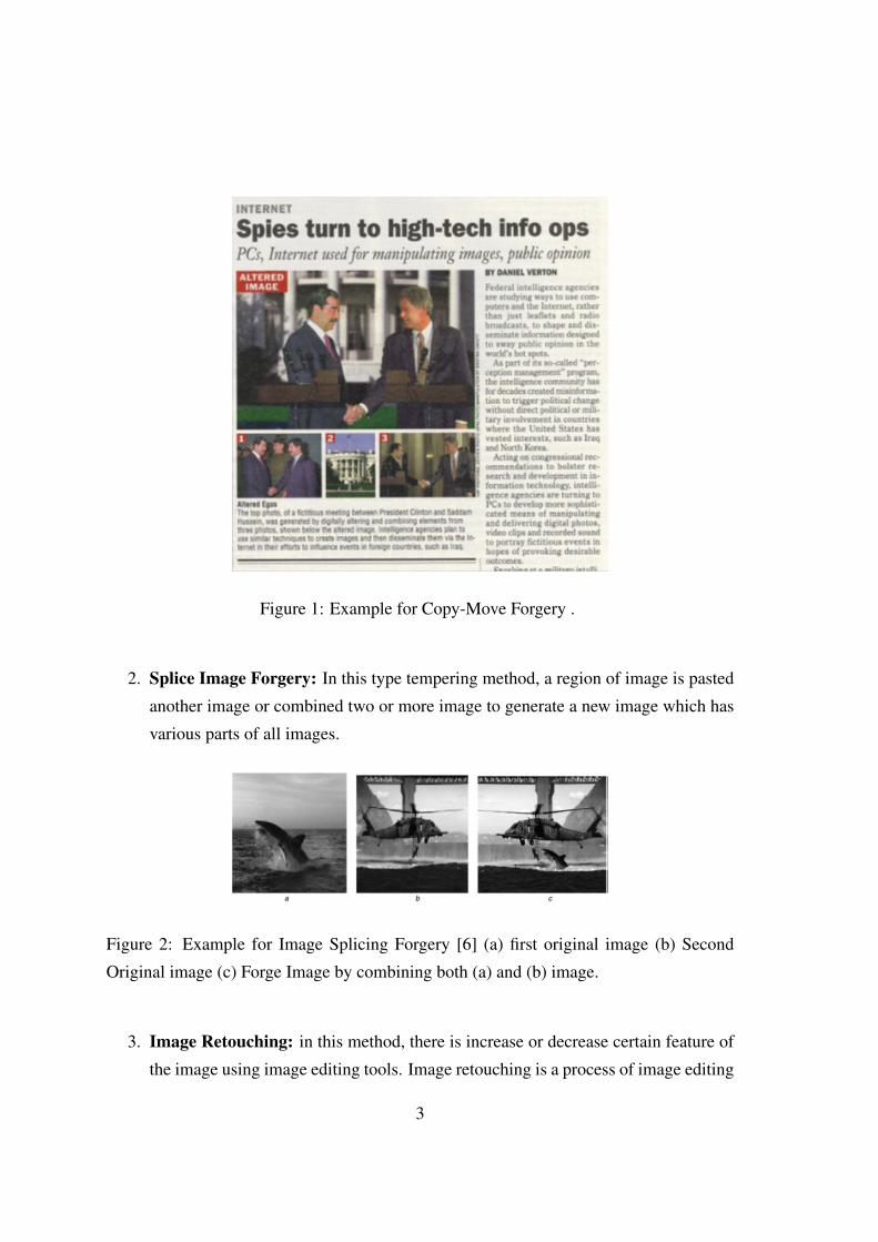
Figure 1: Example for Copy-Move Forgery .
2. Splice Image Forgery: In this type tempering method, a region of image is pasted
another image or combined two or more image to generate a new image which has
various parts of all images.
Figure 2: Example for Image Splicing Forgery [6] (a) first original image (b) Second
Original image (c) Forge Image by combining both (a) and (b) image.
3. Image Retouching: in this method, there is increase or decrease certain feature of
the image using image editing tools. Image retouching is a process of image editing
3
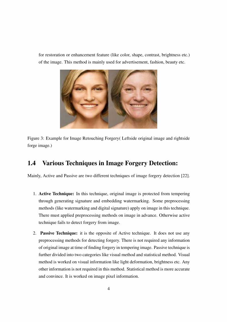
for restoration or enhancement feature (like color, shape, contrast, brightness etc.)
of the image. This method is mainly used for advertisement, fashion, beauty etc.
Figure 3: Example for Image Retouching Forgery( Leftside original image and rightside
forge image.)
1.4 Various Techniques in Image Forgery Detection:
Mainly, Active and Passive are two different techniques of image forgery detection [22].
1. Active Technique: In this technique, original image is protected from tempering
through generating signature and embedding watermarking. Some preprocessing
methods (like watermarking and digital signature) apply on image in this technique.
There must applied preprocessing methods on image in advance. Otherwise active
technique fails to detect forgery from image.
2. Passive Technique: it is the opposite of Active technique. It does not use any
preprocessing methods for detecting forgery. There is not required any information
of original image at time of finding forgery in tempering image. Passive technique is
further divided into two categories like visual method and statistical method. Visual
method is worked on visual information like light deformation, brightness etc. Any
other information is not required in this method. Statistical method is more accurate
and convince. It is worked on image pixel information.
4
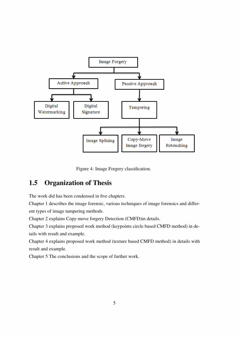
Figure 4: Image Forgery classification.
1.5 Organization of Thesis
The work did has been condensed in five chapters.
Chapter 1 describes the image forensic, various techniques of image forensics and differ-
ent types of image tampering methods.
Chapter 2 explains Copy-move forgery Detection (CMFD)in details.
Chapter 3 explains proposed work method (keypoints circle based CMFD method) in de-
tails with result and example.
Chapter 4 explains proposed work method (texture based CMFD method) in details with
result and example.
Chapter 5 The conclusions and the scope of further work.
5
Chapter 2Literature Survey
2.1 Introduction
Copy move forgery is easiest form in various types of image forgery. It is very simple
to use to temper an image. In copy-move forgery, a region of the image is copied and
pasted on the same image. A group of pixel of image is copied and move another part of
image pasted it on same image. This type is copy-move image forgery. First a specific
region of the image is copied and it is pasted on the same image, is known as Copy-move
forgery. Its used for hiding unwanted region of the image or increasing the numbers of
specific region on the image. Both regions in copy-move forgery have similar properties
like noise level, color and texture. Therefore it is difficult to detect this type of image
forgery.
2.2 Block Diagram of Process of CMFD
A common process is used by various methods for detecting Copy-move forgery.
6
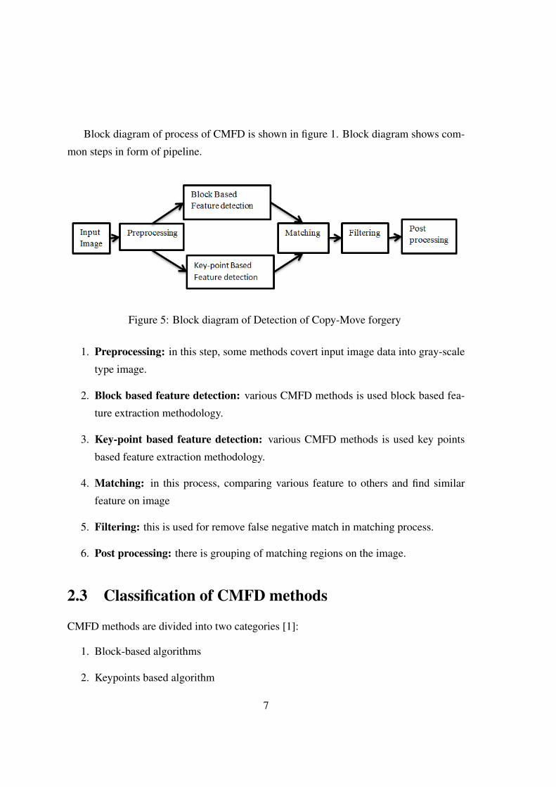
Block diagram of process of CMFD is shown in figure 1. Block diagram shows com-
mon steps in form of pipeline.
Figure 5: Block diagram of Detection of Copy-Move forgery
1. Preprocessing: in this step, some methods covert input image data into gray-scale
type image.
2. Block based feature detection: various CMFD methods is used block based fea-
ture extraction methodology.
3. Key-point based feature detection: various CMFD methods is used key points
based feature extraction methodology.
4. Matching: in this process, comparing various feature to others and find similar
feature on image
5. Filtering: this is used for remove false negative match in matching process.
6. Post processing: there is grouping of matching regions on the image.
2.3 Classification of CMFD methods
CMFD methods are divided into two categories [1]:
1. Block-based algorithms
2. Keypoints based algorithm
7
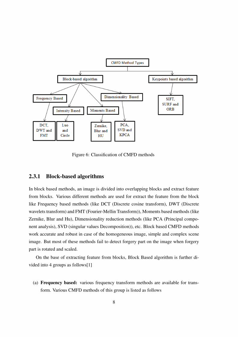
Figure 6: Classification of CMFD methods
2.3.1 Block-based algorithms
In block based methods, an image is divided into overlapping blocks and extract feature
from blocks. Various different methods are used for extract the feature from the block
like Frequency based methods (like DCT (Discrete cosine transform), DWT (Discrete
wavelets transform) and FMT (Fourier-Mellin Transform)), Moments based methods (like
Zernike, Blur and Hu), Dimensionality reduction methods (like PCA (Principal compo-
nent analysis), SVD (singular values Decomposition)), etc. Block based CMFD methods
work accurate and robust in case of the homogeneous image, simple and complex scene
image. But most of these methods fail to detect forgery part on the image when forgery
part is rotated and scaled.
On the base of extracting feature from blocks, Block Based algorithm is further di-
vided into 4 groups as follows[1]
(a) Frequency based: various frequency transform methods are available for trans-
form. Various CMFD methods of this group is listed as follows
8
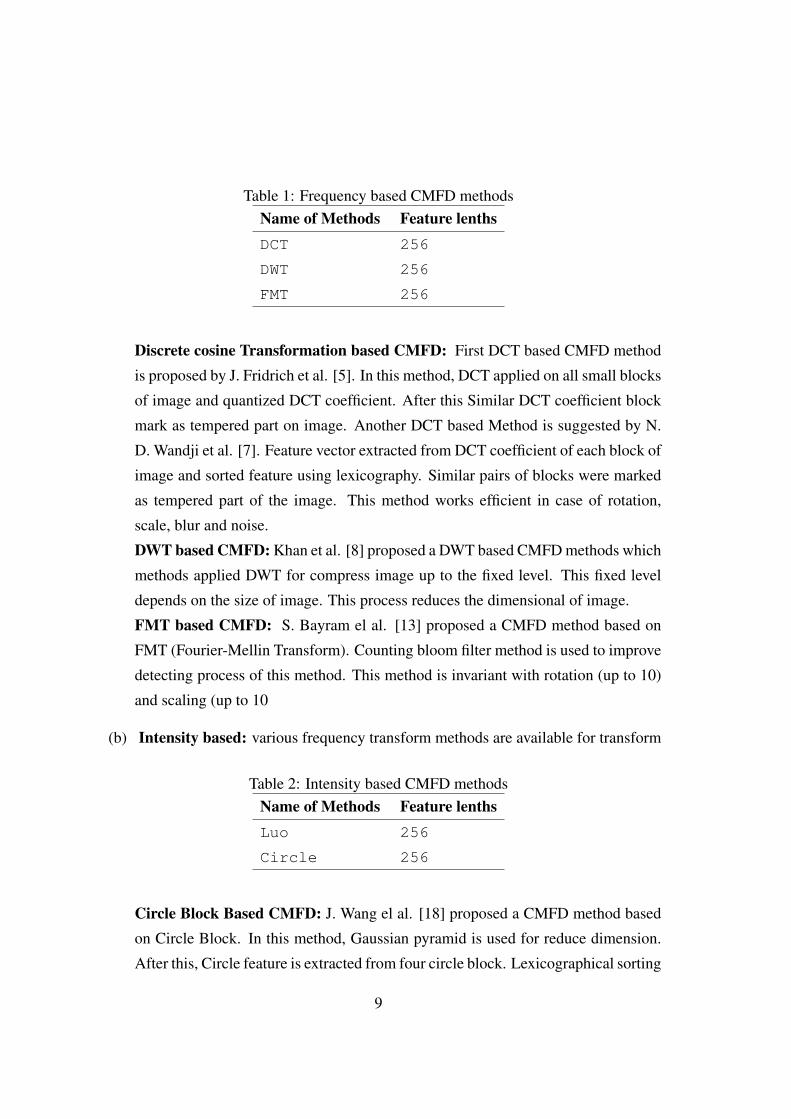
Table 1: Frequency based CMFD methodsName of Methods Feature lenthsDCT 256
DWT 256
FMT 256
Discrete cosine Transformation based CMFD: First DCT based CMFD method
is proposed by J. Fridrich et al. [5]. In this method, DCT applied on all small blocks
of image and quantized DCT coefficient. After this Similar DCT coefficient block
mark as tempered part on image. Another DCT based Method is suggested by N.
D. Wandji et al. [7]. Feature vector extracted from DCT coefficient of each block of
image and sorted feature using lexicography. Similar pairs of blocks were marked
as tempered part of the image. This method works efficient in case of rotation,
scale, blur and noise.
DWT based CMFD: Khan et al. [8] proposed a DWT based CMFD methods which
methods applied DWT for compress image up to the fixed level. This fixed level
depends on the size of image. This process reduces the dimensional of image.
FMT based CMFD: S. Bayram el al. [13] proposed a CMFD method based on
FMT (Fourier-Mellin Transform). Counting bloom filter method is used to improve
detecting process of this method. This method is invariant with rotation (up to 10)
and scaling (up to 10
(b) Intensity based: various frequency transform methods are available for transform
Table 2: Intensity based CMFD methodsName of Methods Feature lenthsLuo 256
Circle 256
Circle Block Based CMFD: J. Wang el al. [18] proposed a CMFD method based
on Circle Block. In this method, Gaussian pyramid is used for reduce dimension.
After this, Circle feature is extracted from four circle block. Lexicographical sorting
9
is used for detecting similar circle feature. This proposed method is invariant with
rotation and post-processing operation like noise, blurring and jpeg compression.
W. Luo et al. [19] proposed a CMDF methods based on intensity feature. In this
method, each block is represented by seven characteristic features. First three fea-
tures are determined by average value of RGB component and next four features
are determined by Y channel value block. Lexicographical sorting is further used
for searching similar feature of blocks on the image.
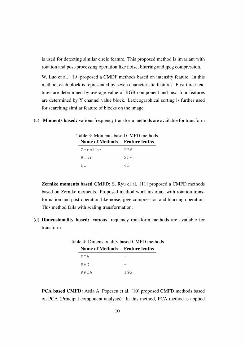
(c) Moments based: various frequency transform methods are available for transform
Table 3: Moments based CMFD methodsName of Methods Feature lenthsZernike 256
Blur 256
HU 45
Zernike moments based CMFD: S. Ryu el al. [11] proposed a CMFD methods
based on Zernike moments. Proposed method work invariant with rotation trans-
formation and post-operation like noise, jpge compression and blurring operation.
This method fails with scaling transformation.
(d) Dimensionality based: various frequency transform methods are available for
transform
Table 4: Dimensionality based CMFD methodsName of Methods Feature lenthsPCA -
SVD -
KPCA 192
PCA based CMFD: Asda A. Popescu et al. [10] proposed CMFD methods based
on PCA (Principal component analysis). In this method, PCA method is applied
10
on small sub-block of the image and lexicographically sorting is used for detect-
ing facsimile regions on the image. This method is invariant with noise and jpeg
compression.
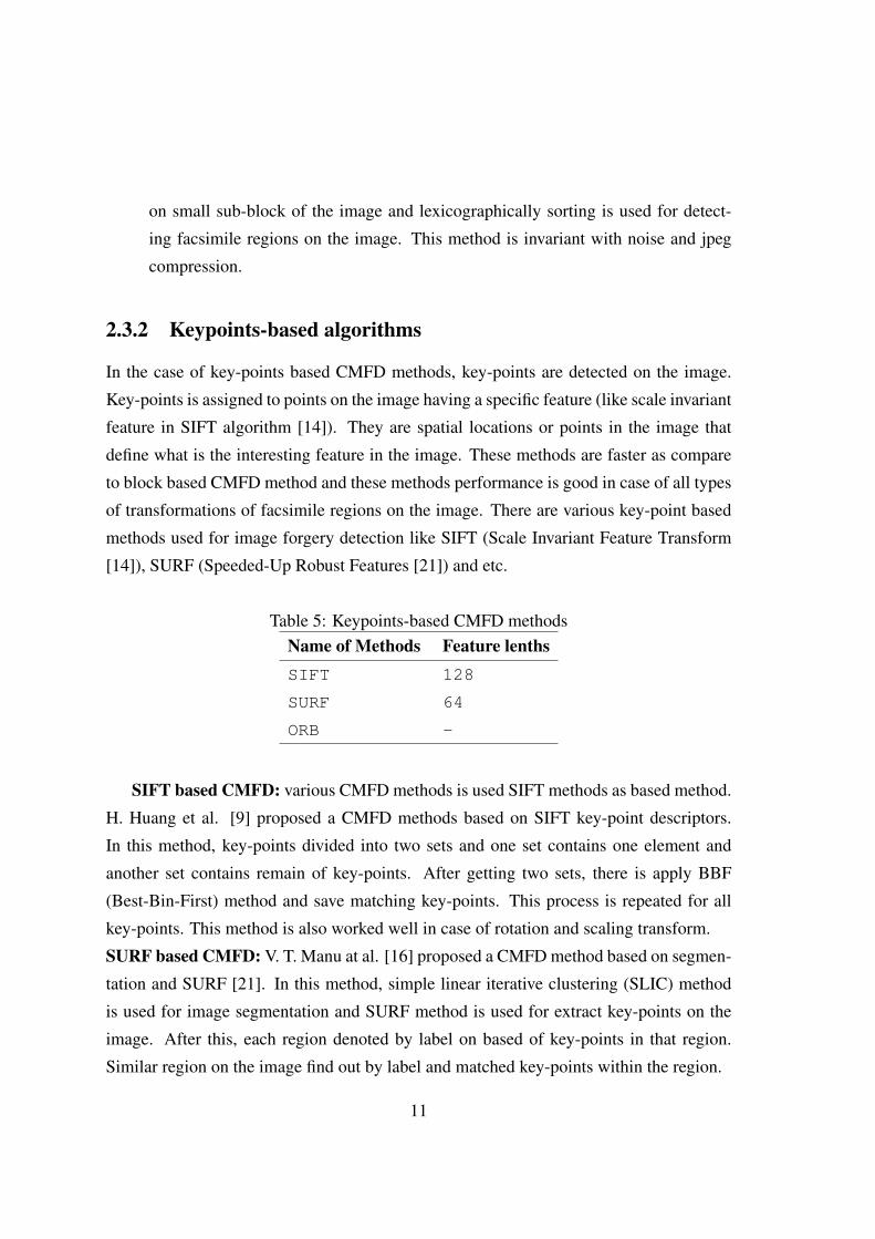
2.3.2 Keypoints-based algorithms
In the case of key-points based CMFD methods, key-points are detected on the image.
Key-points is assigned to points on the image having a specific feature (like scale invariant
feature in SIFT algorithm [14]). They are spatial locations or points in the image that
define what is the interesting feature in the image. These methods are faster as compare
to block based CMFD method and these methods performance is good in case of all types
of transformations of facsimile regions on the image. There are various key-point based
methods used for image forgery detection like SIFT (Scale Invariant Feature Transform
[14]), SURF (Speeded-Up Robust Features [21]) and etc.
Table 5: Keypoints-based CMFD methodsName of Methods Feature lenthsSIFT 128
SURF 64
ORB -
SIFT based CMFD: various CMFD methods is used SIFT methods as based method.
H. Huang et al. [9] proposed a CMFD methods based on SIFT key-point descriptors.
In this method, key-points divided into two sets and one set contains one element and
another set contains remain of key-points. After getting two sets, there is apply BBF
(Best-Bin-First) method and save matching key-points. This process is repeated for all
key-points. This method is also worked well in case of rotation and scaling transform.
SURF based CMFD: V. T. Manu at al. [16] proposed a CMFD method based on segmen-
tation and SURF [21]. In this method, simple linear iterative clustering (SLIC) method
is used for image segmentation and SURF method is used for extract key-points on the
image. After this, each region denoted by label on based of key-points in that region.
Similar region on the image find out by label and matched key-points within the region.
11
ORB based CMFD method: Y. zhu et al. [17] proposed a CMDF method based on ORB
key descriptor. In this method, ORB key descriptor is used to extract key-points on the
image. Hamming distance is used for matching ORB features between two key-points.
RABSAC method is used to remove false result (wrong matched key-pomts).
2.4 Problem Statement
CMFD is an difficult task to detect with all types of attacks. Block based CMFD methods
are better in case of Translation. But these types CMFD method is not well with Ge-
ometric based attacks like rotation, scaling. Key-points based CMFD methods are well
with Geometric based attacks like rotation, scaling. these types method have also some
limitation like it is failed in case of homogeneous area on the image.
12
Chapter 3
CMFD using Key-Points Structure :
Proposed Method
3.1 Introduction
In copy-move type of image forgery, a facsimile of the specific region of the image put
on the same image. Both regions are having similar properties like texture, color, noise,
illumination etc. Therefore, noise and illumination based image forgery detection meth-
ods fail to detect copy-move Forgery (CMF). This types image forgery conceals some
important area of the image under facsimile region. Sometimes, this is used to increase
the number of specific regions of the image and represents false information in the im-
age. Before tampering Image through CMF, various transformations like rotation, scaling,
translation, distortion and combination of more than one transformation can be used on
the facsimile region for making difficult the process of CFM detection (CMFD). Post-
processing methods are used for improving qualities of the image. In post-processing,
the information of original and facsimile region is change slightly. Each Post-processing
13
operation like compression, blurring, color change, brightness change and contrast ad-
justment produce a different impact on CMFD process.
3.2 Proposed Method:
3.2.1 Introduction
keypoints are extracted on image using local feature of Image like Scale invariant place. In
CMDFD, keypoints orientation on original and forgery part are equal and same structure.
Feature value (descriptor values) of these keypoint are similar on both part. Large number
of keypoints on the image is main problem for finding similar orientation of keypoints
regions on the image. In this a work, we find nearest keypoint of a particular keypoint
on the image and considered this keypoint as center of circle. the distacne between both
keypoint should be minimum and greater than threshold distance value. we considered
this distance as radius of circle. the number of circle on the image is less than number of
keypoints. therefore, the number of comparison is reduced. each circle is represented by
mean of keypoint on radius.
3.2.2 Steps of CMFD using Key-Points Structure:
1. SIFT method is used to extract key-points on image.
2. Creating Circle:
• Distance of a key-point from near key-points is determined.
• This distance must be greater than 2 and less than 100. It should minimum
from all near key-points. i.e. 2 < d <100 and d should be minimum distance
or nearest points.
• This distance is considered as radio of that key-point and draw circle on image.
• Make group of both these two points.
3. Mean of feature vector of each group is determined.
| Vmij − Vmik |≤ THv (1)
14
Here, Ckj is mean feature of a group of two key-points and THC is threshold value.
4. Matching circle process: Similar feature circle is marked as similar region on the
image.
3.3 Reference Method: CMFD by matching triangles of
key-points:
3.3.1 Introduction
E. Ardizzone et al. [3] proposed a novel approach which is based on key-points struc-
ture analysis through triangle of Key-point. In Copy-move forgery, original regions and
facsimile regions have similar properties like texture, color etc. structure of key-points
on original and facsimile part is similar to each other. In this method, common key de-
tector methods like SIFT SURF and Harris are used for detecting key-points on image.
Delaunay triangulation method is used for creating triangle using key-points on image.
Delaunay triangulation methods creates non-overlapping triangle onto key-points. These
methods find similar triangles on based of similar color, angle and mean vertex descrip-
tor. In this research paper, there are proposed two different methods like Angle method
and Vertex methods. In Angle method, Angle and color of triangle is used for matching
triangles. In homogeneous case, various triangles have similar color and angle. There-
fore in this case, the number of false matching of triangle increases. In vertex methods,
mean value of vertex descriptor is used for matching triangle. These CMFD methods are
working well on various transform like translation, rotation and scaling. In case of similar
scenes and small number of triangle, these methods produce well output. But in case of
complex scenes and large number of triangle, these methods do not produce well output.
Mainly in this research paper, there are two different methods for CMFD as follows:
1. Color and Angle based triangle matching method
2. Mean vertex descriptors based triangle matching method
These two methods are used for matching triangles and find out copy-move forgery area
on image.
15
These two methods are used for matching triangles and find out copy-move forgery
area on image.
Primary Steps: creating triangle on image is primary steps, which is used by both
methods.
1. Key-points are extract on the image using Key-point detector methods like SIFT,
SURF etc.
2. Arbitrary points are added on the borders of the image.
3. Triangle mesh is constructed onto key points of the image.
3.3.2 Mean Vertex Descriptors based Triangle Matching method:
There are used various steps in this method as follows:
1. Mean Vertex Descriptor (MVD) for each triangle is computed using descriptor
value of each vertex of the triangle. The Mean Vertex Descriptor Vmi for each
triangle calculates using equation (2).
Vmi = (V1i+ V2i+ V3i)/3 (2)
Where Vj = 1.3 i=1, 2, 3 are the descriptor value of three vertex of triangle. Vmi is
the mean vertex descriptor of triangle on the images.
The mean vector for each triangle is n-value array, where n equals to 128 in case of
SIFT and 64 in case of SURF.
2. For sorting Triangle, L1 norm of MVDs of all triangle is used.all triangles are sorted
using MVDS value.
3. In triangle comparison presses, MVD value of triangle is compared to the further
triangles in sorted list of triangle, within a computed fixed window of size ws (fixed
number of triangles).
16
4. If i and j are the number indexes value of two triangle in sorted list of triangle and
Vmi , Vmj are the MVDs of triangles:
| Vmi− Vmj |≤ THv (3)
(j − i) < fws (4)
Where, threshold THv is equal to 0.25 and fws is the size of fixed window.
5. To further remove false positives, they compute the centroids points of triangles
and apply Random Sample Consensus (RANSAC) method to the set of matching
centroids points, to find the set of inliers point. If total number of matches is below
4, RANSAC cannot apply for removing false positive.
3.3.3 Dataset of CMFD by Matching Triangles of key-points:
For result testing purpose, we choose dataset [3] of variety of images.
1. dataset [3]: there are four different directories which contains different types of
geometric based attack on images. Directory D0 contains 50 tampered images and
tampered image contains only translation attack. Directory D1 contains images
which contains only rotations attack. D1 is further divided into three subdirectory
as follow
• D1.1 (rotation range -25 to 25).
• D1.2 (rotation range 0 to 360).
• D1.3 (rotation range -5 to 5).
D2 is further divided into two subdirectory as follow
• D2.1 (scaling range 0.25 to 2).
• D2.2 (scaling range 0.75 to 1.25).
17
3.4 Result Evalution
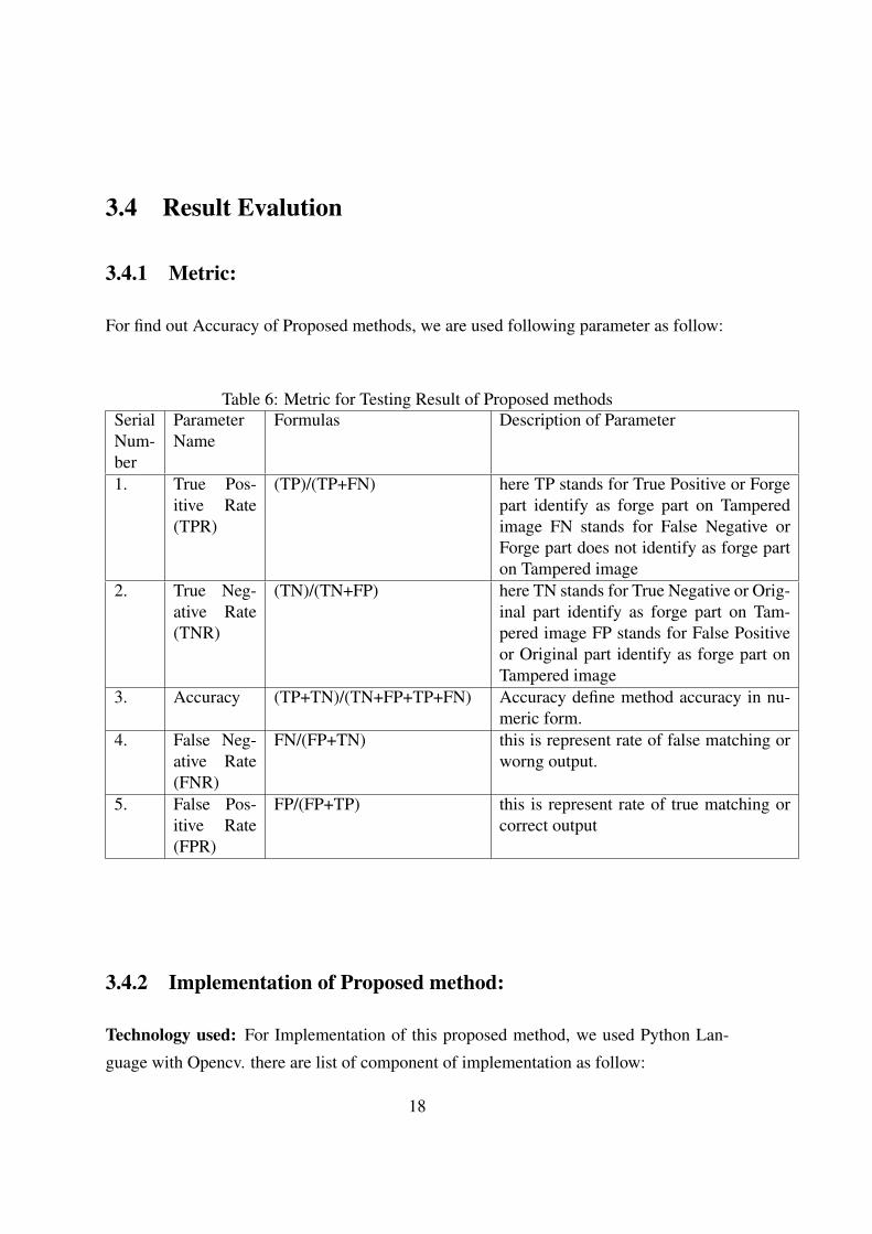
3.4.1 Metric:
For find out Accuracy of Proposed methods, we are used following parameter as follow:
Table 6: Metric for Testing Result of Proposed methodsSerialNum-ber
ParameterName
Formulas Description of Parameter
1. True Pos-itive Rate(TPR)
(TP)/(TP+FN) here TP stands for True Positive or Forgepart identify as forge part on Tamperedimage FN stands for False Negative orForge part does not identify as forge parton Tampered image
2. True Neg-ative Rate(TNR)
(TN)/(TN+FP) here TN stands for True Negative or Orig-inal part identify as forge part on Tam-pered image FP stands for False Positiveor Original part identify as forge part onTampered image
3. Accuracy (TP+TN)/(TN+FP+TP+FN) Accuracy define method accuracy in nu-meric form.
4. False Neg-ative Rate(FNR)
FN/(FP+TN) this is represent rate of false matching orworng output.
5. False Pos-itive Rate(FPR)
FP/(FP+TP) this is represent rate of true matching orcorrect output
3.4.2 Implementation of Proposed method:
Technology used: For Implementation of this proposed method, we used Python Lan-
guage with Opencv. there are list of component of implementation as follow:
18
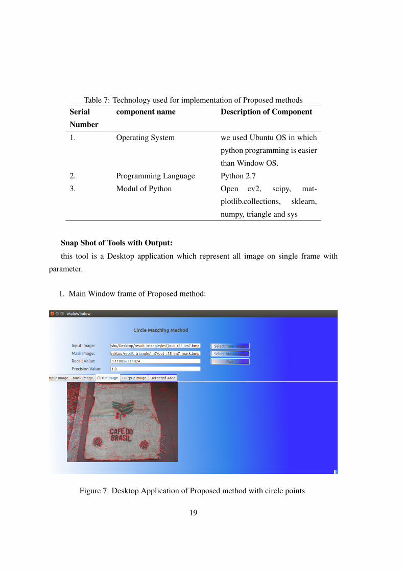
Table 7: Technology used for implementation of Proposed methodsSerialNumber
component name Description of Component
1. Operating System we used Ubuntu OS in which
python programming is easier
than Window OS.
2. Programming Language Python 2.7
3. Modul of Python Open cv2, scipy, mat-
plotlib.collections, sklearn,
numpy, triangle and sys
Snap Shot of Tools with Output:
this tool is a Desktop application which represent all image on single frame with
parameter.
1. Main Window frame of Proposed method:
Figure 7: Desktop Application of Proposed method with circle points
19
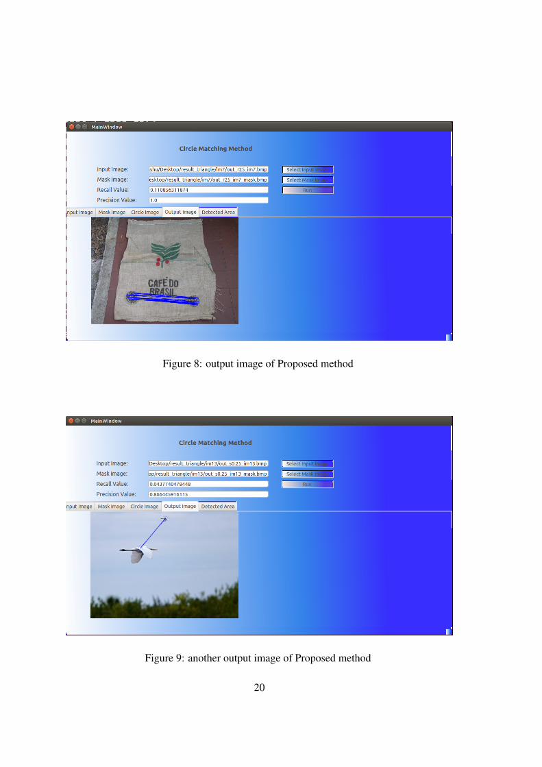
Figure 8: output image of Proposed method
Figure 9: another output image of Proposed method
20
Snap shot of Reference Application :
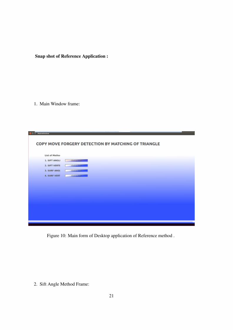
1. Main Window frame:
Figure 10: Main form of Desktop application of Reference method .
2. Sift Angle Method Frame:
21
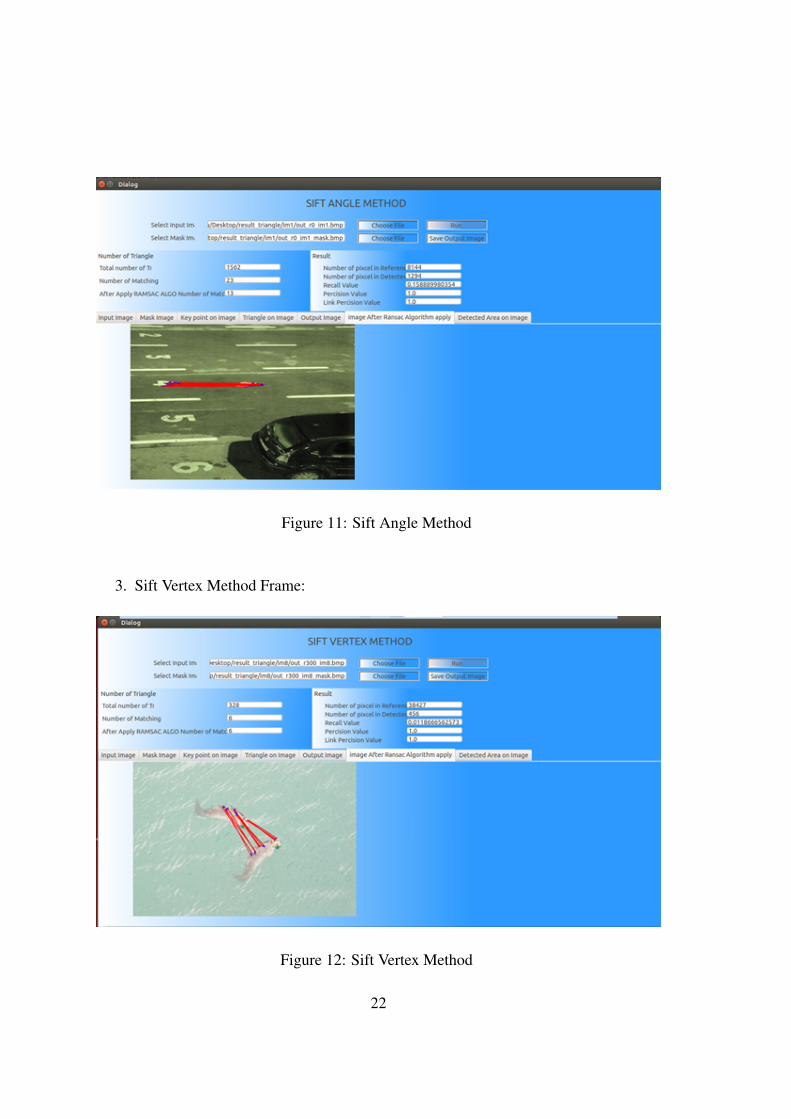
Figure 11: Sift Angle Method
3. Sift Vertex Method Frame:
Figure 12: Sift Vertex Method
22
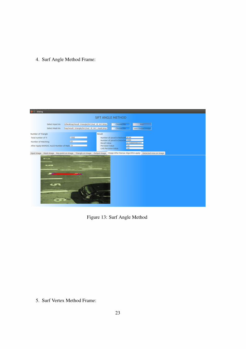
4. Surf Angle Method Frame:
Figure 13: Surf Angle Method
5. Surf Vertex Method Frame:
23
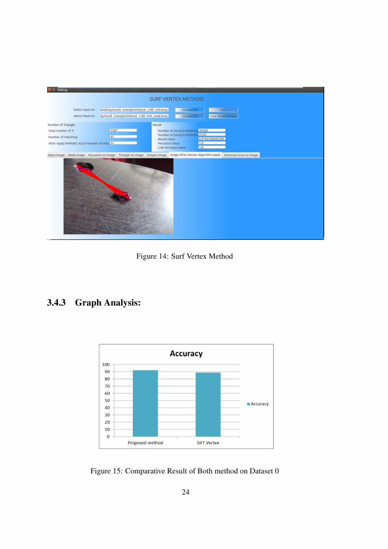
Figure 14: Surf Vertex Method
3.4.3 Graph Analysis:
Figure 15: Comparative Result of Both method on Dataset 0
24
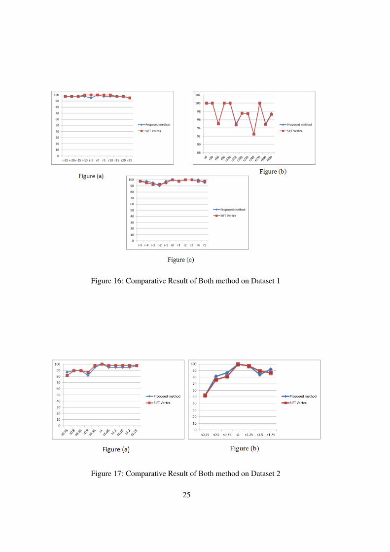
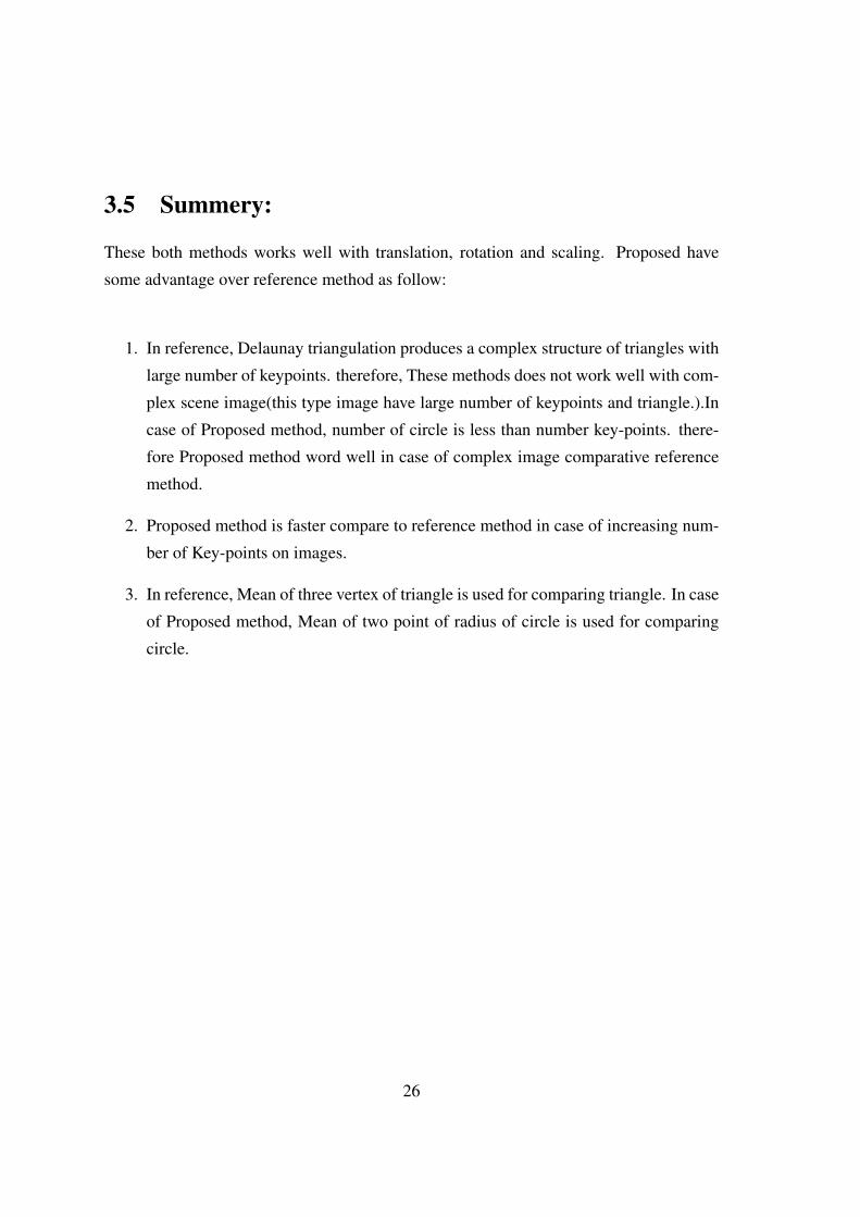
Figure 16: Comparative Result of Both method on Dataset 1
Figure 17: Comparative Result of Both method on Dataset 2
25
3.5 Summery:
These both methods works well with translation, rotation and scaling. Proposed have
some advantage over reference method as follow:
1. In reference, Delaunay triangulation produces a complex structure of triangles with
large number of keypoints. therefore, These methods does not work well with com-
plex scene image(this type image have large number of keypoints and triangle.).In
case of Proposed method, number of circle is less than number key-points. there-
fore Proposed method word well in case of complex image comparative reference
method.
2. Proposed method is faster compare to reference method in case of increasing num-
ber of Key-points on images.
3. In reference, Mean of three vertex of triangle is used for comparing triangle. In case
of Proposed method, Mean of two point of radius of circle is used for comparing
circle.
26
Chapter 4Texture based CMFD Method :
Proposed Method
4.1 Introduction
Localized angular phase (LAP) method is proposed by K. M. Saipullah et al. [2]. This is
an texture descriptor method which is robust in case of illumination, blurring and scaling.
LAP method takes local image pixel and convert it into polar space using polar space
using fixed-radius polar space function p(r,/theta ). After this, fourier transform method
is used to convert polar space value into frequency signal. LAP method is used phase
information for texture descriptor. Phase information of each block is represent by 8-bit
number after analyzing phase information.
4.2 Overview of localized angular phase method:
Mainly in this research paper, there are two different methods for CMFD as follows:
1. Image I is divided into 3x3 sub-image (overlapping blocks).
27
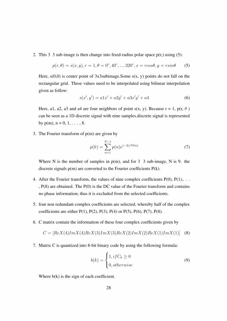
2. This 3 3 sub-image is then change into fixed-radius polar space p(r,) using (5):
p(r, θ) = s(x, y), r = 1, θ = 0◦, 40◦, ..., 320◦, x = rcosθ, y = rsinθ (5)
Here, s(0,0) is center point of 3x3subimage.Some s(x, y) points do not fall on the
rectangular grid. These values need to be interpolated using bilinear interpolation
given as follow:
s(x′, y′) = a1x′ + a2y′ + a3x′y′ + a4 (6)
Here, a1, a2, a3 and a4 are four neighbors of point s(x, y). Because r = 1, p(r, θ )
can be seen as a 1D discrete signal with nine samples.discrete signal is represented
by p(m), n = 0, 1, . . . , 8.
3. The Fourier transform of p(m) are given by
p(k) =N−1∑n=1
p(n)e(−2i/Nkn) (7)
Where N is the number of samples in p(m), and for 3 3 sub-image, N is 9. the
discrete signals p(m) are converted to the Fourier coefficients P(k).
4. After the Fourier transform, the values of nine complex coefficients P(0), P(1),. . .
, P(8) are obtained. The P(0) is the DC value of the Fourier transform and contains
no phase information; thus it is excluded from the selected coefficients.
5. four non redundant complex coefficients are selected, whereby half of the complex
coefficients are either P(1), P(2), P(3), P(4) or P(5), P(6), P(7), P(8).
6. C matrix contain the information of these four complex coefficients given by
C = [ReX(4)ImX(4)ReX(3)ImX(3)ReX(2)ImX(2)ReX(1)ImX(1)] (8)
7. Matrix C is quantized into 8-bit binary code by using the following formula:
b(k) =
1, ifCk ≥ 0
0, otherwise(9)
Where b(k) is the sign of each coefficient.
28
8. By arranging b(1), b(2), . . . , b(7), the 8 bit binary code can be formulated, and a
binomial factor is assigned as 2 for each b(k); hence, it is possible to transform (5)
into a unique LAP number, given by
LAP =8∑
k−1
b(k)2k−1 (10)
This LAP is a decimal value between 0 and 255 resulting from the 8-bit binary
code.
These two methods are used for matching triangles and find out copy-move forgery area
on image.
4.3 Proposed Method:
In our proposed work, we used LAP methods for Extracting feature from each block of
image.
1. Feature extraction: First, we divide the image into overlapping block of 3x3 sizes.
LAP method is applied on each block and extract LAP feature from block. Center
pixel of 3x3 blocks has this value. Instead of boarder pixel, all pixel of image have
LAP feature value.
2. Calculate super LAP feature of block In this step, we calculate super LAP
feature of each block as follow
M =Max(L1, L2, ..., L9) (11)
SLAPi =M − Li (12)
29
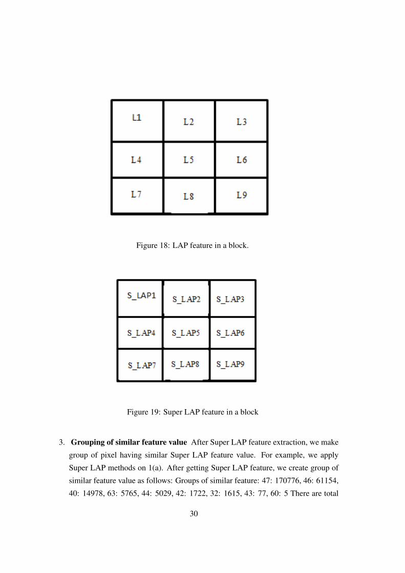
Figure 18: LAP feature in a block.
Figure 19: Super LAP feature in a block
3. Grouping of similar feature value After Super LAP feature extraction, we make
group of pixel having similar Super LAP feature value. For example, we apply
Super LAP methods on 1(a). After getting Super LAP feature, we create group of
similar feature value as follows: Groups of similar feature: 47: 170776, 46: 61154,
40: 14978, 63: 5765, 44: 5029, 42: 1722, 32: 1615, 43: 77, 60: 5 There are total
30
nine group of similar feature. Total 170776 pixels have Super LAP value 47. Total
61154 pixels have Super LAP value 46 and so on. In 1(b), white pixels LAP value
is 47.
4. Selecting group: We select group of least number of pixels value which Super
LAP value represent a specific place of texture.
5. Matching Feature into selecting group In matching process, we compare Super
LAP feature of selected block with each other. If j and k are number of block on
the image then following condition is used for checking.
8∑i=0
| SLAPji − SLAP
ki |= 0 (13)
If Sum of Absolute deviation of Super LAP is equal to zero, then both block j and
k block are considered similar.
4.4 Dataset :
For result testing purpose, we choose three different dataset [3], [4] and [20] of variety of
images.
1. dataset [3]: there are four different directories which contains different types of
geometric based attack on images. We take only Directory D0 images Directory
which contains 50 tampered images and tampered image contains only translation
attack.
2. Dataset [4]: this dataset contains more than 10000 images which contains geomet-
ric and post-operation based attack. We choose only 40 images for testing proposed
methods on translation.
3. Dataset [20]: this dataset contains different types of atmospheric images. We
choose only 100 translation image for testing result.
31
4.5 Result Evalution
4.5.1 Metric:
For find out Accuracy of Proposed methods, we are used following parameter as follow
[23]:
Table 8: Metric for Testing Result of Proposed methodsSerialNum-ber
ParameterName
Formulas Description of Parameter
1. True Pos-itive Rate(TPR)
(TP)/(TP+FN) here TP stands for True Positive or Forgepart identify as forge part on Tamperedimage FN stands for False Negative orForge part does not identify as forge parton Tampered image
2. True Neg-ative Rate(TNR)
(TN)/(TN+FP) here TN stands for True Negative or Orig-inal part identify as forge part on Tam-pered image FP stands for False Positiveor Original part identify as forge part onTampered image
3. Accuracy (TP+TN)/(TN+FP+TP+FN) Accuracy define method accuracy in nu-meric form.
4. False Neg-ative Rate(FNR)
FN/(FP+TN) this is represent rate of false matching orworng output.
5. False Pos-itive Rate(FPR)
FP/(FP+TP) this is represent rate of true matching orcorrect output
4.5.2 Implementation of Proposed method:
Technology used: For Implementation of this proposed method, we used Python Lan-
guage with Opencv. there are list of component of implementation as follow:
32
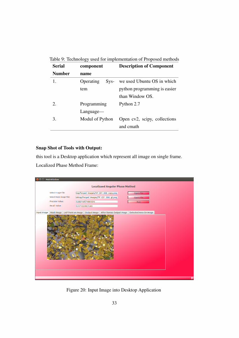
Table 9: Technology used for implementation of Proposed methodsSerialNumber
componentname
Description of Component
1. Operating Sys-
tem
we used Ubuntu OS in which
python programming is easier
than Window OS.
2. Programming
Language—
Python 2.7
3. Modul of Python Open cv2, scipy, collections
and cmath
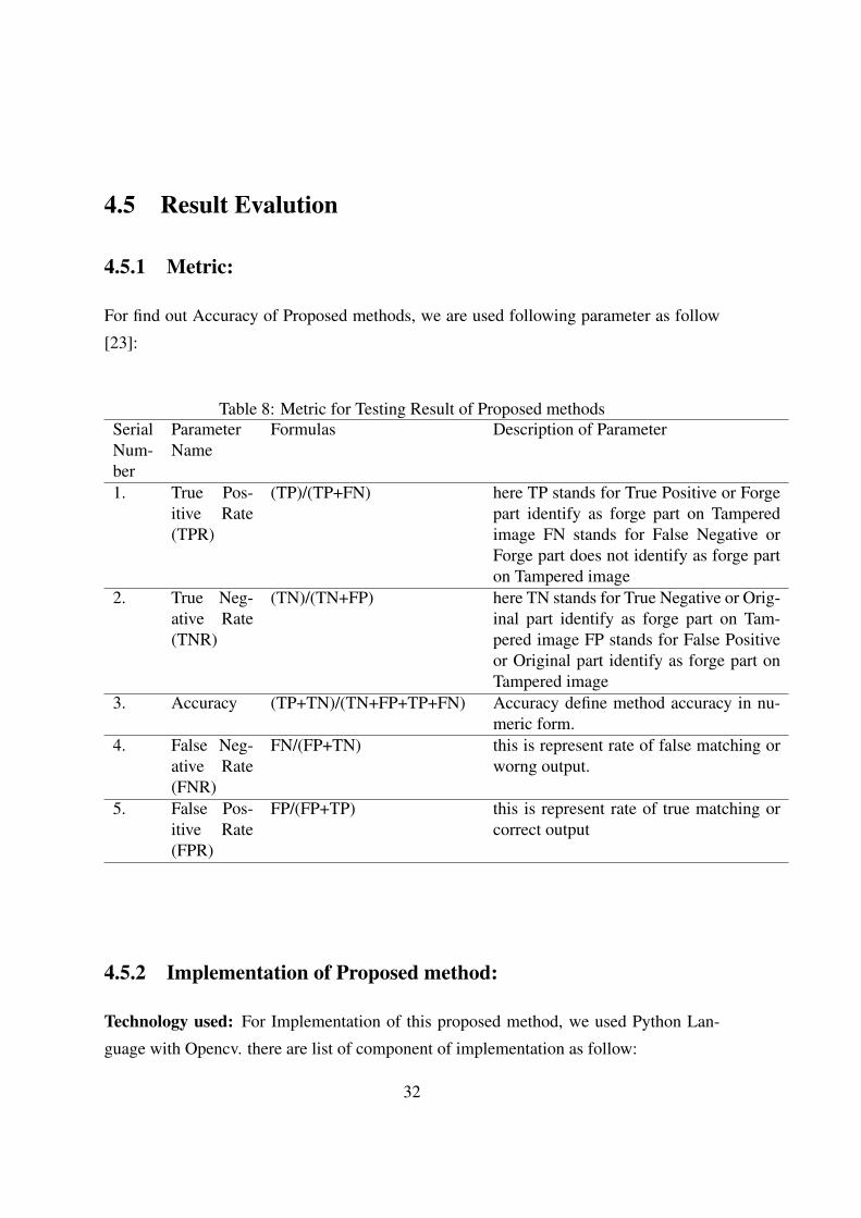
Snap Shot of Tools with Output:
this tool is a Desktop application which represent all image on single frame.
Localized Phase Method Frame:
Figure 20: Input Image into Desktop Application
33
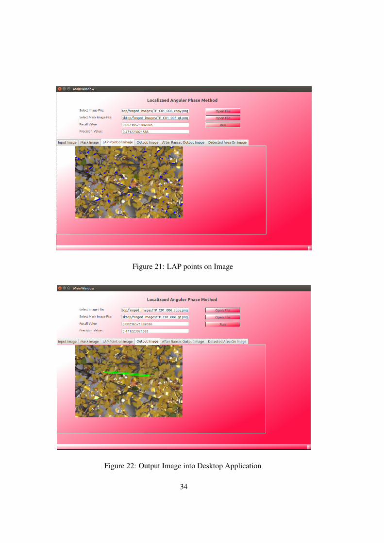
Figure 21: LAP points on Image
Figure 22: Output Image into Desktop Application
34
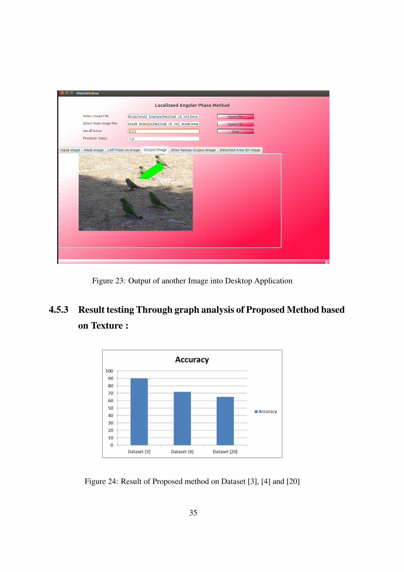
Figure 23: Output of another Image into Desktop Application
4.5.3 Result testing Through graph analysis of Proposed Method basedon Texture :
Figure 24: Result of Proposed method on Dataset [3], [4] and [20]
35
Chapter 5Conclusion and Future Work
Copy-Move Forgery Detection (CMFD) methods work for detecting all types of copy-
move forgery attack like geometric based attack (rotation, translation, and scaling) and
post-operation based attack (blurring, noise, compression etc.).
summary of our study is as follows:
• Block-based methods work well with translation and result accuracy is also good.
but these method fail with rotation and scaling types attacks.
• Keypoints based methods are better in geometric based attacks.
• Keypoints structure based CMFD method are also work well in case of all types of
rotation and scaling.
• keypoints based CMFD methods does not work well with homogeneous area on the
image.
In our First proposed method, we try to improve [3] CMFD methods. We used the
circle based concept to reduce the number of key-points. This method works well with
36
rotation, translation and scaling. In our another proposed methods, we try to detect CMFD
on Texture based Feature like LAP feature. This works well with translation and some
types of rotation and scaling images. This method works well with blurring, illumination
change types images.
Future work: Key-points based CMFD methods work well with geometric and post-
operation based attack. But these methods fails in case of homogeneous area on the image
which Key-point based CMFD method does not extract keypoints. In case of complex
image, these methods generate large number of key-points and take processing time equal
to block-based method. In our future work, we will implement a method which will work
well on both homogeneous and non-homogeneous types image, all types of geometric
and post-operation based attack. for this method, we need a keypoint extraction method
which extract keypoint on homogeneous and non-homogeneous area on the image.there
is also need various types of geometric method for analysis of keypoints orientation on
the image.
37
Author’s Publication
• Vinod Parihar V.T. Manu and B.M. Mehtre, “Copy-Move Forgery Detection using
Key-Points Orientation”, Submitted to IEEE Trans. on Information forensics and
Security, in May, 2016.
38
References
[1] V. Christlein, C. Riess, J. Jordan,C. Riess and E. angelopoulou. (2012, Nov.).
“An evaluation of popular Copy-move forgery Detection approaches”. IEEE Trans.
on Information forensics and Security. [Online]. 7(6), pp. 18411854. Available:
http://ieeexplore.ieee.org/xpl/RecentIssue.jsp?punumber=10206
[2] K. M. Saipullah and D.H. Kim, “A robust texture feature extraction using the localized
anular phase”, Multimed Tools Appl (2012) 59:717747.
[3] E. Ardizzone, A. Buno and G. Mazzola. (2015, Oct.). “Copy-Move Forgery
Detection by Matching Trianles of Keypoints”. IEEE Trans. on Informa-
tion forensics and Security. [Online]. 10(10), pp. 20842094. Available:
http://ieeexplore.ieee.org/xpl/RecentIssue.jsp?punumber=10206
[4] D. Tralic, I Zupancic et. “CoMoFodNew Database for copy-move Forgery Detec-
tion”, in International symposium on EIMAR, IEEE, 2013, pp. 49-54.
[5] J. Fridrich, D.Soukal and J. Likas, “Detection of copy-move forgery in digital im-
ages”, in processings of digital forensic research workshop, 2003.
[6] H. Farid, “Image forgery detection (a survey)”, Signal processing magazine, IEEE,
2009.
39
[7] N. D. Wandji et., “detection of copy-move forgery in digital images based on DCT”,
The Scientific world Journal, Volume 2014.
[8] Khan, S., kulkarni, A, “Detection of copy-move forgery using multi resolution char-
acteristic of discrete wavelet transform”, International conference on workshop on
emerging treads in technology. ICWET11, New York, NY, USA, 2011, pp. 127-131
[9] H. Huang, W. Guo and Y. Zhang, “Detection of copy-move forgery in digital images
using SIFT algorithm”, in Pacific-Asia Workshop on Computational intelligence and
industrial application, IEEE, 2008, 2, pp. 272-276.
[10] A. Popescu and H. Farid, “Exposing digital forgeries by detecting duplicated image
region [Technical Report]”. 2004-515, Hanover, Department of Computer Science,
Dartmouth College. USA, 2004.
[11] S.J. Ryu, M.-J. Lee, and H.-K. Lee, “Detection of copy-rotatemove forgery using
zernike moments”, in Information Hiding, 2010, pp. 51-65.
[12] Y. Li, “Image copy-move forgery detection based on polar cosine transform and
approximate nearest neighbor searching”, Forensic science international, vol. 224,
pp. 59-67, 2013.
[13] S. Bayram, H. T. Sencar, and N. Memon, “An efficient and robust method for detect-
ing copy-move forgery”, in Acoustics, Speech and Signal Processing, 2009. ICASSP
2009. IEEE International Conference on, 2009, pp. 1053-1056.
[14] Lowe, D.G., “Distinctive image features from scale-invariant keypoints”. Interna-
tional Journal of Computer Vision 60(2), 91110 (2004)
[15] I. Amerini, L. Ballan, R. Caldelli, A. D. Bimbo, L. D. Tongo and G. Serra, “Copy
move forgery detection and localization by means of robust clustering with J- Link-
age”, Signal processing, Image communication, 2013.
[16] VT Manu, BM Mehtre “Detection of Copy-Move Forgery in Images Using Seg-
mentation and SURF”, Advances in Signal Processing and Intelligent Recognition
Systems, 2016 Springer.
40
[17] Y. Zhu, X. Shen and H. Xhen,“Copy-move forgery detection based on scaled ORB”
, Multimedia tools Application, 2015-Springer.
[18] J. Wnag, G. Liu, H. Li and Z. Wnag, “Detection of Image Region Duplication Forger
using Model Circle-Block”, in ICMINS,2009.
[19] W. Luo, J. Huang and G. Qiu, “Robust Detection of region Duplication forgery in
digital images”, in IC on Pattern Recognition, 2006.
[20] D. Cozzolino, G. Poggi and L. Verdoliva, “Copy move forgery detection based on
patchmatch”, ICIP, IEEE,2014.
[21] H. Bay, T. Tuytelaars, and L. V. Gool., “SURF: speed up robust Features”, Computer
VisionECCV 2006, pp. 404417. Springer (2006).
[22] T. Qazi, K. Hayat, S. U. Khan, S. A. Madani, I. A. Khan, J. Kolodziej, H. Li, K. C.
yow and C. Z. Xu, “Survey on bind image forgery detection”, IET Image Process.,
2013, 7(7), pp. 660-670.
[23] Harpreet Kaur, Jyoti Saxena and Sukhjinder Singh, “ Simulative Comparison of
Copy- Move Forgery Detection Methods for Digital Images”, International Journal
of Electronics, Electrical and Computational System , 2015
41
![A Survey on Forensic Images for Forgery Detection and ...iaetsdjaras.org/gallery/10-january-396.pdfB. Copy- Move digital image forgery [11] is a specific type of image manipulation,](https://img.pdfslide.net/doc/110x75/5ed9fe6628db2d5ca2493780/-a-survey-on-forensic-images-for-forgery-detection-and-b-copy-move-digital.jpg)


![Digital Image Forgery Detection Using Zernike Moment and … · 2018-05-09 · forgery basics and various types of digital image forgery and forgery detection techniques [5]. Resmi](https://img.pdfslide.net/doc/110x75/5f47098d266de9297350ffa0/digital-image-forgery-detection-using-zernike-moment-and-2018-05-09-forgery-basics.jpg)